ftw 175-2 wireless monitoring system - flash … ftw 175-2 wireless monitoring system is available...
TRANSCRIPT

Flash Technology, 332 Nichol Mill Lane, Franklin, TN 37067www.spx.com/en/flash-technology
(615) 261-2000
FTW 175-2Wireless Monitoring System
Reference Manual
Part Number 7911752
SERIAL NUMBER


FTW 175-2 Revision 3 – 8/14/2015 i
Front Matter
AbstractThis manual contains information and instructions for installing, operating and maintainingthe FTW 175-2 Wireless Monitoring System.
CopyrightCopyright © 2015, Flash Technology, Franklin, TN, 37067, U.S.A.
All rights reserved. Reproduction or use of any portion of this manual is prohibited withoutexpress written permission from Flash Technology and/or its licenser.
Trademark AcknowledgementsFlash Technology and Vanguard are registered trademarks of SPX Corporation.
All other trademarks and product names mentioned are properties of their respectivecompanies, and are recognized and acknowledged as such by Flash Technology.
DisclaimerWhile every effort has been made to ensure that the information in this manual is complete,accurate and up-to-date, Flash Technology assumes no liability for damages resulting fromany errors or omissions in this manual, or from the use of the information contained herein.Flash Technology reserves the right to revise this manual without obligation to notify anyperson or organization of the revision.
In no event will Flash Technology be liable for direct, indirect, special, incidental, orconsequential damages arising out of the use of or the inability to use this manual.
WarrantyWith proper installation and with normal operating conditions, Flash Technology warrants allcomponents, for 1 year.

ii Revision 3 – 8/14/2015 FTW 175-2
Table of Contents
Front Matter ............................................................................................................................... iTable of Contents...................................................................................................................... iiList of Figures .......................................................................................................................... iiiList of Tables ........................................................................................................................... iiiSection 1 – Introduction............................................................................................................ 1
Introduction........................................................................................................................... 1Description............................................................................................................................ 1Specifications........................................................................................................................ 1
Section 2 – Initial On-Site Wireless Service Check ................................................................. 3Unpacking ............................................................................................................................. 3Verify Wireless Service ........................................................................................................ 3Finding the Best Install Location.......................................................................................... 3
Section 3 – Mounting and Installation ...................................................................................... 4Mounting............................................................................................................................... 4Installation............................................................................................................................. 4
AC Power Wiring ............................................................................................................. 4Dry Contact Input Wiring ................................................................................................. 4RS-485 Wiring.................................................................................................................. 4Antenna Mounting Bracket............................................................................................... 4Grounding ......................................................................................................................... 5
Status Indicator LED’s.......................................................................................................... 6Section 4 – Activation............................................................................................................. 13
Monitoring .......................................................................................................................... 13Section 5 – Recommended Spare & Replaceable Parts.......................................................... 14
Customer Service ................................................................................................................ 14Ordering Parts ..................................................................................................................... 14
Return Material Authorization (RMA) Policy........................................................................ 15

FTW 175-2 Revision 3 – 8/14/2015 iii
List of Figures
Figure 1-1 – FTW 175-2 Internal Wiring & Component Layout ............................................. 2Figure 2-1 – Wireless Service Label......................................................................................... 3Figure 3-1 – AC Termination ................................................................................................... 5Figure 3-2 – Dry Contact Input Label....................................................................................... 5Figure 3-3 – PCB 9039 Layout and External Wiring ............................................................... 7Figure 3-4 – Enclosure Mounting Footprint ............................................................................. 8Figure 3-5 – RS-485 Installation with FTB Strobe System...................................................... 9Figure 3-6 – RS-485 Installation with FLC 36XX ................................................................. 10Figure 3-7 – Antenna Types ................................................................................................... 11Figure 3-8 – Antenna Universal Mounting Bracket ............................................................... 12Figure 4-1 – Wireless Number................................................................................................ 13
List of Tables
Table 3-1 – PCB 9039 LED’s................................................................................................... 6Table 3-2 – Modem LED’s ....................................................................................................... 6Table 5-1 – Major Replaceable Parts...................................................................................... 14Table 5-2 – Optional Items ..................................................................................................... 14


FTW 175-2 Revision 3 – 8/14/2015 1
Section 1 – Introduction
IntroductionThe FTW 175-2 Wireless MonitoringSystem is available configured for serviceprovided by AT&T or Verizon 3Gwireless networks. Monitoring of siteequipment is provided through RS-485communications and/or four (4) drycontact inputs. The unit also monitors sitepower.
Equipment monitoring through RS-485communications is available with all FlashTechnology FLC series controllers andany FTB strobe system equipped with a9038 or 4747 (Ver. 6.9 or higher) PCB.
Dry contacts are typically alarm relaysprovided by equipment for externalmonitoring of alarm conditions. Eachinput of the FTW 175-2 can be configuredby Flash Technology’s NationalOperations Center (NOC) to alarm oneither open or closed status. Alarm onopen is preferred for fail safemonitoring.
All alarm and communication monitoringis handled by the NOC.
Important: Before permanentlyinstalling and/or wiring the wirelessmonitoring unit, power-up thesystem on-site to ensure wirelessservice in your area. Refer to Section2 for detailed instructions.
When removing power from theequipment, ensure that the red wireto the battery is disconnected first.Reconnect battery after work iscompleted.
DescriptionThe component layout and internal wiringof the unit is shown in Figure 1-1. The drycontact inputs are located on J2 of PCB9039 as shown in Figure 3-3.
SpecificationsPhysical
13.33H x 11.30W x 7.11D inches(External)
11 lbs.Electrical
AC Voltage 120 VAC, 60 HzPower 7VABattery Operation 4+ hrs

2 Revision 3 – 8/14/2015 FTW 175-2
Figure 1-1 – FTW 175-2 Internal Wiring & Component Layout

FTW 175-2 Revision 3 – 8/14/2015 3
Section 2 – Initial On-Site Wireless Service Check
UnpackingInspect shipping cartons for signs ofdamage before opening them. Checkpackage contents against the packing listand inspect each item for visible damage.Report damage claims promptly to thefreight handler.
Verify Wireless ServiceImportant: The following steps willverify wireless service in your areaand must be performed at thelocation where the unit is to beinstalled. A label located on theinside front cover of the monitoringunit is provided to call attention tothis process. Figure 2-1 depicts thelabel noted above.
To verify that cellular service is availableat the site, perform the following stepsprior to installation:
1. Apply 120 VAC to the unit andthen monitor the green LEDindicator labeled “ACTIVE” onPCB 9039 for status. See Figure 3-3 for location of the LED. Ifwireless service is available, the
LED will indicate signal strengthby a series of short blinks (1-5).
2. Once a wireless signal is found, theunit will attempt to connect to theNOC. This operation is indicatedby rapid blinking of the LED.
3. If communication is achieved, the“ACTIVE” LED will be solid onwith short blinks to indicate signalstrength (1-5).
Note: This process may take severalminutes. See Figure 2-1 for completedetails of the “Active” LED.
Finding the Best InstallLocationMove the external antenna to differentlocations to find the maximum signalstrength available at the site, as indicatedby the number of ACTIVE LED blinks.This will help determine the locationwhere the FTW 175-2 should be mounted.
Upon successful completion of these steps,shut off power to the unit and proceedwith installation.
Prior to installation, apply power to the unit and observe the "ACTIVE" LED to verify service.Please note that this sequence may take several minutes to complete.
OFF - Initializing.OFF with short BLINKS - Wireless network found. Number of short blinks
indicates signal strength (1 - 5).RAPID BLINKING - Communication with NOC underway. Waiting for verification.ON with short BLINKS - Communication with NOC verified. Number of short blinks
indicates signal strength (1 - 5). Begin installation.
Contact the NOC at (800) 821-5825 for technical support.
ATTENTION
P/N 3905210Rev A
Figure 2-1 – Wireless Service Label

4 Revision 3 – 8/14/2015 FTW 175-2
Section 3 – Mounting and Installation
MountingThe base of the unit has four (4) mountingfeet as shown in Figure 3-4. Mountinghardware is not included.
Installation
AC Power Wiring
AC Power terminal block TB1incorporates MOV1 and Fuse F1 forincreased protection against AC Powertransients. Also, fuseholder TB1 acts as apower disconnect to the unit. Grasp thefuseholder on the sides and pull forward todisconnect power.
Connect 120 VAC power to terminalblock TB1 (L, N, GND) as shown inFigure 3-1, but leave power turned offuntil you are ready for activation (seeSection 4). The terminal block uses spring-cage contacts to provide rugged, trouble-free connections which are vibration-proofand gas-tight, thus providing long-termstability. The conductor contact force isdetermined by the spring tension and so isindependent of the user tightening torqueas with screw type terminals.
To install a wire, follow these steps:1. Strip the insulation, exposing 0.4
inch (10 mm) or more ofconductor.
2. Insert a standard 1/8” widthscrewdriver into the rectangularslot and push. This causes thespring clip to open.
3. Insert the conductor fully into theround terminal compartment andthen remove the screwdriver. Theconductor automatically makescontact.
4. Check that contact is made toconductor metal and not insulation.
Dry Contact Input Wiring
Connect the equipment to be monitoredvia dry contact inputs as shown in Figure3-3. A label has been provided on theinside cover of the unit to record eachinput, up to four (4), that is connected.Figure 3-2 depicts the dry contact inputlabel.
RS-485 Wiring
Connect the equipment to be monitoredvia RS-485 as shown in Figures 3-5 or 3-6.Figure 3-3 shows the layout of the PCB9039 board.
Antenna Mounting Bracket
The supplied Antenna Universal MountingBracket Kit (PN 1905355) providesmultiple mounting options for the antenna;permitting installation in the optimumlocation for best signal strength andreliable communication. The bracket’sdesign permits mounting on wall, Uni-strut, or pole (Figure 3-8). Regardless ofthe mounting method selected, the antennabracket must be grounded with a minimum14 AWG ground wire connected to the sitegrounding system. Observe propergrounding procedures.
The bracket is made from ferrous metaland galvanized for long life. The bracket’stop plate accommodates either themagnetic mount or body mount styleantenna as shown in Figure 3-7. Thecellular antenna must be mounted in thecenter position of the bracket. The bracketalso permits mounting of a photodiode (orphotocell) in either of the two side holeson the top plate.

FTW 175-2 Revision 3 – 8/14/2015 5
The FTW 175-2 is shipped with theantenna preinstalled and the antennacable’s SMA connector torqued tospecification onto the modem’s antennaconnector for optimal performance. Do notremove or disconnect unless replacing themodem or antenna.
To install the bulkhead mount styleantenna, loosen the antenna mounting nutand washer and slide the antenna mountthrough the bracket’s center holeslot. Tighten the hardware.
Important: For best communicationperformance and to minimizepotential for surge damage to themodem radio module, it is veryimportant that the supplied antennamounting bracket be used formounting the antenna and that thebracket be grounded with a minimum14 AWG Ground wire connected tothe site Grounding System. Also, ifany excess antenna cable is coiledup, the coil diameter must not beless than 18 inches.
Grounding
To provide increased immunity fromlightning damage to the FTW 175-2, it isessential that the Ground Lug located inthe upper left corner of the FTW baseplate(Figure 1-1) be properly connected by a 2AWG conductor to the site GroundingSystem. Observe proper Groundingprocedures.
Figure 3-1 – AC Termination
Figure 3-2 – Dry Contact Input Label
6 Revision 3 – 8/14/2015 FTW 175-2
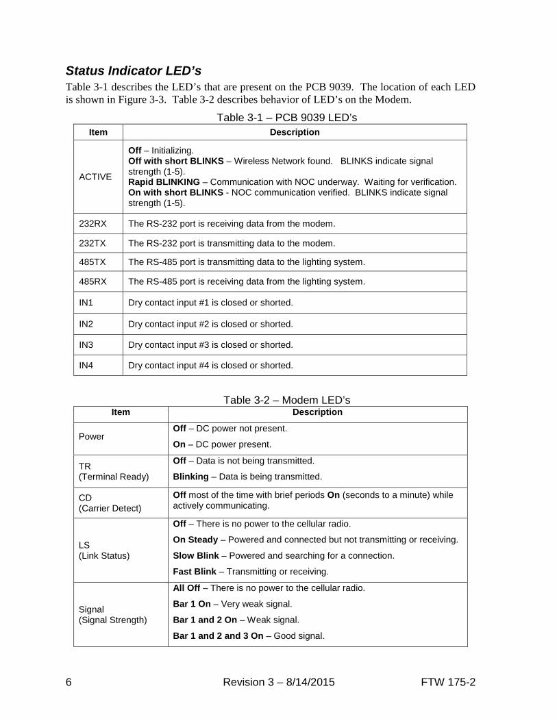
Status Indicator LED’sTable 3-1 describes the LED’s that are present on the PCB 9039. The location of each LEDis shown in Figure 3-3. Table 3-2 describes behavior of LED’s on the Modem.
Table 3-1 – PCB 9039 LED’s
Table 3-2 – Modem LED’sItem Description
PowerOff – DC power not present.
On – DC power present.
TR(Terminal Ready)
Off – Data is not being transmitted.
Blinking – Data is being transmitted.
CD(Carrier Detect)
Off most of the time with brief periods On (seconds to a minute) whileactively communicating.
LS(Link Status)
Off – There is no power to the cellular radio.
On Steady – Powered and connected but not transmitting or receiving.
Slow Blink – Powered and searching for a connection.
Fast Blink – Transmitting or receiving.
Signal(Signal Strength)
All Off – There is no power to the cellular radio.
Bar 1 On – Very weak signal.
Bar 1 and 2 On – Weak signal.
Bar 1 and 2 and 3 On – Good signal.
Item Description
ACTIVE
Off – Initializing.Off with short BLINKS – Wireless Network found. BLINKS indicate signalstrength (1-5).Rapid BLINKING – Communication with NOC underway. Waiting for verification.On with short BLINKS - NOC communication verified. BLINKS indicate signalstrength (1-5).
232RX The RS-232 port is receiving data from the modem.
232TX The RS-232 port is transmitting data to the modem.
485TX The RS-485 port is transmitting data to the lighting system.
485RX The RS-485 port is receiving data from the lighting system.
IN1 Dry contact input #1 is closed or shorted.
IN2 Dry contact input #2 is closed or shorted.
IN3 Dry contact input #3 is closed or shorted.
IN4 Dry contact input #4 is closed or shorted.

FTW 175-2 Revision 3 – 8/14/2015 7
Figure 3-3 – PCB 9039 Layout and External Wiring

8 Revision 3 – 8/14/2015 FTW 175-2
Figure 3-4 – Enclosure Mounting Footprint

FTW 175-2 Revision 3 – 8/14/2015 9
Figure 3-5 – RS-485 Installation with FTB Strobe System

10 Revision 3 – 8/14/2015 FTW 175-2
Figure 3-6 – RS-485 Installation with FLC 36XX

FTW 175-2 Revision 3 – 8/14/2015 11
Figure 3-7 – Antenna Types
Body Mount Antenna
Magnetic Mount Antenna

12 Revision 3 – 8/14/2015 FTW 175-2
Figure 3-8 – Antenna Universal Mounting Bracket
Note: Dual band magnetic mount antenna shown.
Wall MountUse screws to mount to the inside or outside wall of ashelter.(Screws are not included in the kit.)
Horizontal Uni-strut MountUse spring-nuts to mount to Uni-strut.(Spring-nuts are not included in the kit.)
Vertical Pole or H-frame post MountUse 3” U-bolt (included) to mount to pole or H-frame post.The bracket permits use of larger U-bolts, up to 5”.

FTW 175-2 Revision 3 – 8/14/2015 13
Section 4 – Activation
Monitoring
Important: Before leaving the site,ensure that the battery is connected.
When removing power from theequipment, ensure that the red wireto the battery is disconnected first.Reconnect battery after work iscompleted.
Once the installation is complete, followthe procedure below to activate the serviceand begin monitoring:
1. Before calling the NOC, please beprepared to provide the followinginformation:
The wireless number for this unit.See Figure 4-1. The label is locatedon the inside front cover.
Your name, contact number andcompany.
If monitoring an FCC registeredtower site, the site number andFCC number.
Descriptions of the items beingmonitored by each input.
2. Re-apply power to the equipment andobserve the “Active” LED shown inFigure 3-3. Once the LED is “On withshort BLINKS”, communication withthe NOC has been established. Thisprocess may take several minutes.Refer to Figure 2-1 and Table 3-2 forcomplete details of the “Active” LED.
3. Secure the external antenna on theAntenna Mounting Bracket in alocation which provides maximumsignal strength as indicated by thenumber of ACTIVE LED blinks
4. Connect the red wire to + (Positive)and the black wire to – (Negative) onthe battery as shown in Figure 1-1.
5. Call 1-800-821-5825 to initiatemonitoring while on-site. The NOCtechnician will request several tests tobe performed to verify correctinstallation and operation of thesystem.
6. Please note that once the unit ispowered and communication isestablished, it will automatically senda message to the NOC to initiateservice and billing will begin.
IP 10.243.16.1
Figure 4-1 – Wireless Number

14 Revision 3 – 8/14/2015 FTW 175-2
Section 5 – Recommended Spare & Replaceable Parts
Customer ServiceCustomer Service: (800) 821-5825
Telephone: (615) 261-2000
Facsimile: (615) 261-2600
Shipping Address:
Flash Technology332 Nichol Mill LaneFranklin, TN 37067
Ordering PartsTo order spare or replacement parts, contact customer service at 1-800-821-5825.
Table 5-1 – Major Replaceable Parts
Reference Description Part Number
MODEMModem Wireless, Verizon 5905103
Modem Wireless, AT&T 5905102
HARNESS Harness, FTW 175-2 Modem Signal 4905206
BATTERY 12V Battery 4991875
POWER Power Supply 5905202
PCB 9039 PCB FTW 175-2 2903913
MODEM RESET Modem Reset PCB 2903920
ANTENNADual Band Magnetic Mount 4905227
Wide Band Body Mount 4905230
ANTENNA Kit Antenna Mounting Bracket 1905355
TB1 FUSE 3 AMP 3AB 4150218
TB1 Varistor 130V 6901079
Table 5-2 – Optional Items
Reference Description Part Number
CABLE RS-485; Single Pair, 22 AWG, Red/Black 5905302
CABLE Dry Contacts; 4 Pair, 22 AWG, Red/Black 5993101

RMA Policy Revision 2014B
Return Material Authorization (RMA) Policy
IF A PRODUCT PURCHASED FROM FLASH TECHNOLOGY MUST BE RETURNED FOR ANYREASON (SUBJECT TO THE WARRANTY POLICY), PLEASE FOLLOW THE PROCEDUREBELOW:
Note: An RMA number must be requested from Flash Technology prior to shipment of anyproduct. No returned product will be processed without an RMA number. This number will bethe only reference necessary for returning and obtaining information on the product’s progress.Failure to follow the below procedure may result in additional charges and delays. Avoidunnecessary screening and evaluation by contacting Technical Support prior to returningmaterial.
1. To initiate an RMA: Call Flash Technology’s National Operations Center (NOC) at (800-821-
5825) to receive technical assistance and a Service Notification number. The following
information is required before a Service Notification number can be generated:
• Site Name/Number / FCC Registration number/ Call Letters or Airport Designator
• Site Owner (provide all that apply – owner, agent or subcontractor)
• Contractor Name
• Contractor Company
• Point of Contact Information: Name, Phone Number, Email Address, Fax Number and Cell
Phone (or alternate phone number)
• Product’s Serial Number
• Product’s Model Number or part number
• Service Notification Number (if previously given)
• Reason for call, with a full description of the reported issue
2. The Service Notification number will then serve as a precursor to receiving an RMA number
if it is determined that the product or equipment should be returned. To expedite the RMA
process please provide:
• Return shipping method• Shipping Address• Bill to Address• Any additional information to assist in resolving the issue or problem
3. Product within the Warranty Time Period
a. If to be returned for repair;
• RMA # is generated
• Once product is received and diagnosed;
• Covered under warranty – product is repaired or replaced
• Not covered under warranty – quote is sent to the customer for a bench fee of
$350 plus parts for repair
• If the customer does not want the product repaired, a $50 test fee is
charged before being returned
b. If advance replacement;
• Purchase order may be required before the advance replacement order is created
• RMA # is generated and the advance replacement order is created
• Once product is received and diagnosed;
• Covered under warranty – credit given back if PO received
• Not covered under warranty – credit will not be applied to PO
• Flash Technology has sole discretion in determining warranty claims. Flash
Technology reserves the right to invoice for parts advanced if the associated failed
parts are not returned within 15 days of issue or if product received is diagnosed to be
non-warranty.

Revision 2014B RMA Policy
• Advance replacements will be shipped ground unless the customer provides alternative
shipping methods.
4. Product outside the Warranty Time Period
a. For Xenon System board repair; a purchase order is required at time of request for a RMA #
for a standard $350 repair bench fee
• RMA # is generated with the PO attached
• If the board is deemed non-repairable after diagnosis, the customer is notified. If the
customer purchases a new board, the repair bench fee is waived. If the customer does
not buy a new board, a $50 test fee is charged before being returned or scrapped.
b. For all other products; no purchase order is required to return the product for diagnosis
• RMA # is generated
• Once product is diagnosed, quote is sent to the customer for a bench fee of $350 plus
parts for repair
• Once the purchase order is received, the product will be repaired and returned
• If the customer does not want the product repaired, a $50 test fee is charged
before being returned or scrapped.
5. After receiving the Flash Technology RMA number, please adhere to the following
packaging guidelines:
• All returned products should be packaged in a way to prevent damage in transit. Adequatepacking should be provided taking into account the method of shipment.
Note: Flash Technology will not be responsible for damaged items if product is notreturned in appropriate packaging.
6. All packages should clearly display the RMA number on the outside of all RMA shipping
containers. RMA products (exact items and quantity) should be returned to:
Flash TechnologyAttn: RMA #XXX332 Nichol Mill LaneFranklin, TN 37067
7. All RMA numbers:
• Are valid for 30 days. Products received after 30 days may result in extra screening and delays.• Must have all required information provided before an RMA number is assigned.