fttp osp design to maximize coverage and upgradeability · fujitsu network communications inc. 2801...
TRANSCRIPT

FTTP OSP Design to Maximize Coverage and Upgradeability

FUJITSU NETWORK COMMUNICATIONS INC.2801 Telecom Parkway, Richardson, Texas 75082-3515Telephone: (972) 690-6000(800) 777-FAST (U.S.)us.fujitsu.com/telecom
1
IntroductionNow that FTTP technology is being deployed after years of discussion and several false starts, one has to ask, “What took so long?” Was there no compelling reason for the carriers to invest in new technologies? Was the technology too expensive to deploy? Was there a lack of training and a lack of familiarity with deploying fiber verses deploying copper? Was there the risk of stranding investment of the copper OSP? The answer to all of these questions is a resounding yes. A relaxation of regulations, a significant drop in wireline service demand and strong competition from multiple sources have given the carriers plenty of incentive to deploy fiber in the residential and business plant. The technology is still too expensive, but with strong demand for the FTTP service and strong competition, the market will quickly resolve this issue. There was and still is a training and familiarity issue with deploying fiber verses copper. Copper facilities have been deployed for over a century and the methods and procedures for installing equipment and facilities are well known. As with any new technology, fiber deployment processes and procedures will take some time to become commonplace, but after a few years they will also become well known and no longer pose a challenge. The stranded copper investment is sunk cost. There is not much to be done about it, except limit further copper facility investments and possibly a reclamation effort for the copper material.
It is very clear that copper lines will quickly go the way of the propeller airliner, the black and white television set and the party-line phone. As these older technologies were replaced by newer technologies, new infrastructures were required. For instance, longer runways were required for the jet airliners and wider TV channels were required to transmit the color information for the color television sets. This took large investments, time and mistakes before the new infrastructures were completely in place. FTTP will be no different. It will take large investments, a period of trial and error and, of course, time for the copper facilities to be replaced with fiber.
The most critical and therefore the most expensive element of an FTTP network is not the electronics that go on each end of the access network. It is not the routers, the customer premise equipment, nor the switches or gateways. The most critical element of the deployment is the OSP facilities. It is the fiber, the splitters, the fiber housing, the connectors and, most of all, the labor that are the bulk of the cost of deployment. The fiber facilities need to be considered for today’s deployment initially with GPON, but they also need to be capable of reuse with tomorrow’s technologies. This paper will recommend certain practices for how fiber might be efficiently deployed.
For your convenience, a list of acronyms can be found at the end of this document.

FUJITSU NETWORK COMMUNICATIONS INC.2801 Telecom Parkway, Richardson, Texas 75082-3515Telephone: (972) 690-6000(800) 777-FAST (U.S.)us.fujitsu.com/telecom
2
Access AnalogiesPON technologies have an early telephony analogy that could be applicable to its rollout and upgradeability. In the early days of telephone service, many customers shared a phone line (known as a “party-line”) to amortize the labor and copper facilities expenses. Back then, the copper drops were expensive to deploy (particularly in rural areas) and so the telephone companies put in a single line to serve multiple customers. In the early days, the lines were typically underutilized (call duration times and call frequencies were low), so the customers didn’t seem to mind the inconvenience of sharing a line. Call alerting was based on a unique cadenced ring pattern per home or on a ringing frequency selective phone.
In many respects, we are now in the early days of FTTP deployments. Currently fiber can provide much more capacity than most customers use so there is an underutilization of today’s FTTP network. Having a shared network today is not a consumer concern so long as mechanisms are in place to allow for the protection of privacy.
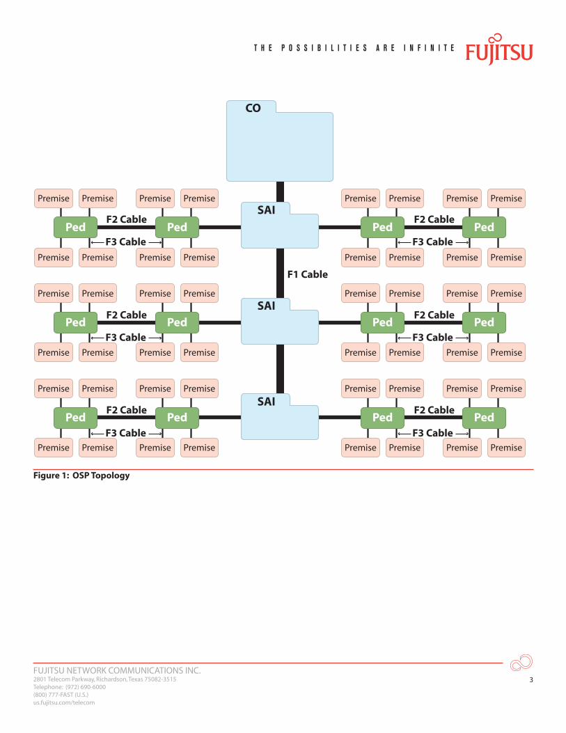
As before, having a shared network provides a significant cost savings to the carrier, and in the case of FTTP, is one of the key enablers behind current deployments. As time passed and telephone service demand grew, the party-line became passé, and customers started demanding private lines. The carriers were required to upgrade their network to add copper resources to both the F1 and F2 facilities (see Figure 1). With good early planning, today’s carriers can avoid the same migration issue with fiber. Currently, the F1 fiber facility is shared while the F2 and F3 facilities are unique to a customer. As customer bandwidth demands increase (and they will increase), one can reduce the split ratio or use WDM technologies to provide more capacity. A reduction in the split ratio requires additional fiber in the F1 facility, which can be a large cost to the carrier. WDM technologies (one private wavelength per customer) can also be very expensive due to the need to upgrade both the ONT and OLT equipment to accommodate for the additional wavelengths. A compromise that is worth considering is utilizing a hybrid PON technology that effectively reduces the split ratio without adding F1 fiber facilities or upgrading the ONTs.
In the long run, either the F1 fiber facilities will be increased or WDM technology will become economical enough that each home will have either a dedicated fiber or a dedicated wavelength. However, a transition technology is required to bridge the gap from where we are today to where we might be twenty years from now. An HGPON technology can serve as this bridge. This HGPON system continues to use the GPON protocol as its MAC layer protocol, but it supports a wide-band optical receiver on its ONTs so that multiple CWDM wavelengths can be utilized downstream. This allows for more capacity downstream, which effectively reduces the split ratio without the need to upgrade the ONTs. The OLT ports still require an upgrade to support the multiple wavelengths, but this is in one centralized location instead of being spread out to thousands of locations.
FUJITSU NETWORK COMMUNICATIONS INC.2801 Telecom Parkway, Richardson, Texas 75082-3515Telephone: (972) 690-6000(800) 777-FAST (U.S.)us.fujitsu.com/telecom
3
CO
SAIPremisePremise
PremisePremise
Ped
PremisePremise
PremisePremise
Ped
PremisePremise
PremisePremise
PedF2 Cable
F2 Cable
F3 Cable
F2 Cable
F2 Cable
F2 Cable
F1 Cable
F2 Cable
PremisePremise
PremisePremise
Ped
PremisePremise
PremisePremise
Ped
PremisePremise
PremisePremise
Ped
PremisePremise
PremisePremise
Ped
PremisePremise
PremisePremise
Ped
PremisePremise
PremisePremise
Ped
PremisePremise
PremisePremise
Ped
PremisePremise
PremisePremise
Ped
PremisePremise
PremisePremise
Ped
SAI
SAI
F3 Cable
F3 Cable
F3 Cable
F3 Cable
F3 Cable
Figure 1: OSP Topology

FUJITSU NETWORK COMMUNICATIONS INC.2801 Telecom Parkway, Richardson, Texas 75082-3515Telephone: (972) 690-6000(800) 777-FAST (U.S.)us.fujitsu.com/telecom
�
COSAI
PedSubscriber 1
F2 Section (Distribution)to other neighborhoods
fed from the same SAI
F1 Section (Fiber Feeder)Typically conduit,
direct buried or aerial
200-pair bundlen x 50-pair
bundles
42 pair
10 pair
Subscriber 2
Subscriber 3 Subscriber 4
F3
F2 Section (Distribution)Typically buried or aerial
F2 Section (Distribution)Typically buried or aerial
Business, Subscriber 32
N x 50 pair bundles2 pair
F3
PedPedSubscriber 28 Subscriber 29
Subscriber 30 Subscriber 31
F3 Section (Drop)Typically buried or aerial,
2 or 3 copper pair F3 Section (Drop)Typically buried or aerial,2 or 3 pair to each home
Typically serving200 to 500
copper pairs
Figure 2: A Traditional Copper Access OSP

FUJITSU NETWORK COMMUNICATIONS INC.2801 Telecom Parkway, Richardson, Texas 75082-3515Telephone: (972) 690-6000(800) 777-FAST (U.S.)us.fujitsu.com/telecom
5
COSAI
PedSubscriber 1
F2 Section (Distribution)to other neighborhoods
fed from the same SAI
F1 Section (Fiber Feeder)Typically conduit,
direct buried or aerial
18-fiber bundle 144-fiber bundle
144 fiber bundle
28 fibers
32 fibers
5 fibers
Subscriber 2
Subscriber 3 Subscriber 4
F3
F2 Section (Distribution)Typically buried or aerial
F2 Section (Distribution)Typically buried or aerial
Business, Subscriber 32
1 fiber
F3
PedPed
Subscriber 28 Subscriber 29
Subscriber 30 Subscriber 31
F3 Section (Drop)Typically buried or aerial F3 Section (Drop)
Typically buried or aerial
Splitter Hub
Figure 3: FTTP Typical Fiber Layout
Splitter LocationsThe diagram shown in Figure 1 shows the topology of today’s copper network. In a typical copper application, the SAI is where cross-connects are made (see Figure 2). The F1 cable comes from the CO to the local neighbor. The F2 cable is distributed along easements in the neighborhood, typically along the backyard border connecting properties. The F3 cable is the last drop from the easement to the subscriber’s house. In most cases, the F1 copper pairs are fewer in number than the F2 copper pairs since there are, on average, two or three F2 pairs per home, while the F1 cable rate is approximately 1.2 pairs per home. Traditionally, the SAI is where the F1 pairs are connected to the F2 pairs and serves as the first distribution branch. In an FTTP application, the same logic applies. The F1 fibers are fewer in number than the F2 fibers. The splitter hub would be the location where the F1 fibers coming from the CO are brought into the neighborhood. The F2 fibers are distributed throughout the neighborhood along the easements, and the F3 fibers are the drops to the customer premises.
As shown in Figure 3, the splitter hub is also shown as an SAI. It makes sense that the splitter hub would reside in the same location as the SAI since it really serves the same purpose (i.e., to cross-connect fibers to the distributed cables).

FUJITSU NETWORK COMMUNICATIONS INC.2801 Telecom Parkway, Richardson, Texas 75082-3515Telephone: (972) 690-6000(800) 777-FAST (U.S.)us.fujitsu.com/telecom
6
To Connectorize or Splice, That is the QuestionThere is an ongoing debate between field splicing the network or utilizing a pre-connectorized network. There is a cost tradeoff between making things flexible with connectorization or splicing all connections. As shown in Figure 3, the F2 fiber is typically in a bundle (1�� fibers) that goes past multiple hand-holes or pedestals. At each hand-hole, the fiber is broken out of the sheath for the F3 drops. Splicing is necessary at each hand-hole to either connectorize the F3 or to splice an F3 drop directly.
Of all of the fiber segments (F1, F2, or F3), the one most likely to be cut or damaged is the F3 drop because it goes onto customer premises. As a result, the copper F3 drop is historically replaced every five to ten years. There is no reason to believe that homeowners will not dig in their yards just because they have now have fiber to their home. So the question remains; which is the better path, a connectorized F3 or a spliced F3? The answer is that it depends on several factors. The driving logic should be the quick and easy replacement of the F3 section so that customers can quickly regain service. Utilizing pre-connectorized cables requires the truck fleet to carry a full set of different lengths of cables and an ONT slack tray to contain the excess fiber. Utilizing field splicing requires the truck fleets to only carry a roll of F3 cable, but it also requires splicing equipment and trained staff.
It seems logical that aerial-based F3 drops would not need replacing with near the frequency of a buried F3. It is unlikely that a customer can damage an aerial cable, so it seems to make sense that an aerial cable can be made a more permanent fixture than a buried F3 cable.
It also seems logical for the ONT to be connectorized regardless of the F3’s topology. Since ONTs do contain active electronics and may need to be replaced or upgraded over the years, a connector-based ONT seems a necessity.
Connectorizing the splitter hub makes sense from a flexibility perspective. If one of the F2 fibers gets damaged, being able to easily move the splitter port from one fiber to another fiber can shorten the outage significantly. Although it does require a significant amount of initial splicing (all of the F2 fibers and F1 fibers), they are all at one central location and can be done fairly quickly by trained staff.
Bigger is not Always BetterThe majority of the cost of the OSP is in the F2 and F3 facilities. Putting in hand-holes, preparing splices, adding connectors, etc., takes a large amount of capital and labor costs. It is important to size the network carefully before immediately assuming that more fiber is better in the F2 facility. Putting in a larger fiber bundle than is necessary can result in unnecessary costs of the network. Not only is the cost of the fiber bundle more, but a larger bundle requires a larger splice area (larger hand-hole), which can be a significant expense. Further, a larger fiber bundle costs more to splice as more fibers are required to be spliced, connectorized, etc. A larger fiber bundle is also just more difficult to install and handle in the field, heavier on the pole in an aerial application, etc.
FUJITSU NETWORK COMMUNICATIONS INC.2801 Telecom Parkway, Richardson, Texas 75082-3515Telephone: (972) 690-6000(800) 777-FAST (U.S.)us.fujitsu.com/telecom
7
Growth PatternsThe bandwidth of fiber is sometime described as being infinite. It really is capable of supporting thousands of wavelengths, with each wavelength operating at tens of Gbps. Today a single wavelength can practically support �0 Gbps. But, this is at a relatively high price and requires a technology with very special designs and a well-controlled environment. The more common interoffice rate today is 10 Gbps. This also requires designs for WDM applications and environmentally controlled buildings are necessary to house the temperature sensitive equipment. It is not yet a candidate for deployment in rural communities, however GPON rates today can support bit-rates of up to 2.5 Gbps fairly economically. Unfortunately, this bandwdth must be shared with neighbors. Still, these customers get an average of nearly 80 Mbps and can also access the entire 2.5 Gbps (only 100 Mbps due to the Ethernet connection) if the customer surfs the Internet during off-peak hours.
Just two decades ago, personal computer processing power was limited to tens of KHz. Today, it is measured in GHz—one million times faster. According to Moore’s law, in another generation, the computing power advancement will be measured in the THz. As the processing power increases, so do the applications such as streaming digital HDTV, which could require major advances in optical technologies. For decades, the network advances didn’t keep up with the advances in computing power, primarily due to the F2 and F3 copper drops. DSL helped to bridge the gap for a while and helped promote the popularity of broadband access. But even now DSL is running out of gas or the drop loop lengths need to be impractically short to support wider bandwidths. Once the masses got an initial taste of broadband, trying to keep their bandwidth thirst in check was impossible. The chains are now off the carriers for deploying fiber technologies, so customer demand will be the carriers’ only constraint.
The C's and D’s of WDMWDM provides multiple wavelengths on a fiber—each of a slightly different "color" of light. The term CWDM was coined after technology advanced to provide DWDM where the wavelengths are separated by only a few nanometers. Today, DWDM is limited to inter-office networks due to its relatively high cost—due in large part to the necessity for very stable lasers and associated environmental thermal control. CWDM can easily be deployed in less robust environments and laser stability is of much less concern. Typical CWDM networks provide eight wavelengths on a fiber, and each wavelength can carry the same bandwidth so that the capacity of the fiber increases eight-fold.
Although GPON is only now starting to be generally deployed, its capacity should be recognized as being practically limited. The current limit seems high, but applications will grow rapidly and then consume its capacity. Although the bit-rate could be increased to 10 Gbps, the lasers are still very expensive. Further, a single wavelength increase would mandate the upgrading of the OLT and all of the ONTs on the network. The easy and early answer to increasing the bandwidth capacity is CWDM.

FUJITSU NETWORK COMMUNICATIONS INC.2801 Telecom Parkway, Richardson, Texas 75082-3515Telephone: (972) 690-6000(800) 777-FAST (U.S.)us.fujitsu.com/telecom
8
CWDM also offers substantial near-term financial advantages for the general deployment of GPON. Use of CWDM in the access feeder (or F1 facility) can reduce the fiber cable size by a factor of eight while still fully supporting the full GPON architecture. For example, an 18-fiber cable could be used in lieu of a 1��-fiber cable. Cable and splicing costs would be dramatically reduced and the GPON architecture could be more generally deployed. When additional bandwidth beyond the current GPON capacity is later needed, relatively small additional F1 cables could be added that also utilize CWDM.
Use of CWDM on the distribution (or F2) side of the splitter hub should also be considered to reduce GPON OSP costs dramatically. Without CWDM, each living unit requires a dedicated F2 fiber from the FDT to the home (unless a distributed splitter model is used) for access to services provided over the GPON network. In many practical cases, the F2 cables contain 216 fibers as they leave the fiber hub and most often there are two or more F2 cables (one going "East" and one going "West"). Due to the high splicing costs associated with tapering, the F2 cables often travel 2000 or more feet from the fiber hub without changing size, even though many of the fibers within the cable have been terminated near the fiber hub and are then “dead” in the sheath. In addition, the cost of hand-holes for access to the fibers is much higher when the F2 cable size exceeds 1�� fibers. CWDM could be used to significantly reduce F2 cable sizes and related costs to further promote the successful deployment of GPON.
Fiber cable types are very specific in the inter-office networks. They are all of the SMF type, but the specific type of SMF is very important due to certain delay (dispersion) effects over very long distances. In the local loop OSP, the distances are relatively short so that accumulated dispersion is fairly small. In addition, dispersion is of essentially no concern at the relatively low GPON current transmission rate of 2.5 Gbps. Higher transmission rates, such as 10 Gbps, are another matter. In the inter-office network, 10 Gbps rates require dispersion compensation to insure that the optical receiver can determine whether the arriving data bit represents a one or a zero. Therefore, the specific type of SMF deployed for GPON may be irrelevant as long as the GPON transmission rate remains low. CWDM can keep the GPON rate low by adding wavelengths in lieu of increasing the transmission rate while also increasing bandwidth capacity.

FUJITSU NETWORK COMMUNICATIONS INC.2801 Telecom Parkway, Richardson, Texas 75082-3515Telephone: (972) 690-6000(800) 777-FAST (U.S.)us.fujitsu.com/telecom
9
ConclusionsFTTP is finally here and is starting to be deployed en masse. However, it is important that upgradeability be considered as part of today’s deployment. Some may believe that the fiber that is being installed today will never be exhausted. This may be the case, but it is much more likely that the fiber will be exhausted relatively soon given that only customer demand (and not government regulations or monopoly economics) will be the limiting constraint on upgradeability.
In order to be able to upgrade the network economically, items need to be considered such as what technology is the most economical for the upgrade (CWDM, DWDM, or higher single wavelength bitrates)? What are the fewest number of network elements that need to be touched during the upgrade? Will the fiber that is currently being installed today support this upgrade?
Although a shared network is the economical reality of today, today’s carriers should not make the same mistake that their telephony forefathers made on upgrading the party-line network. The network needs to be designed today to be upgradeable for the future.
References[1] Sunan Han and Sam Lisle, “Triple-Play Transport Architecture Alternatives and Economic Considerations”,
submitted to IEEE Network Magazine for the special topic of Convergence of Internet and Broadcasting Systems to be published in March, 2007.
[2] Stephen Smith, “Business Class Services over a GPON Network”, Proceedings of OFC/NFOEC, Anaheim CA, March 5-10, 2006, Section/Page: JThB96.
[3] William Yue, “How GPON Deployment Drives the Evolution of the Packet-Based Network”, Digest of the FTTH Conference, Las Vegas, NV, October 2-5, 2006.

FUJITSU NETWORK COMMUNICATIONS INC.2801 Telecom Parkway, Richardson, Texas 75082-3515Telephone: (972) 690-6000(800) 777-FAST (U.S.)us.fujitsu.com/telecom
10
Acronym Descriptor
CO Central Office
CWDM Coarse Wavelength Division Multiplexing
DSL Digital Subscriber Line
DWDM Dense Wavelength Division Multiplexing
FDT Fiber Distribution Terminal
FTTP Fiber to the Premises
Gbps Gigabits per Second
GHz Gigahertz
GPON Gigabit Passive Optical Networking
HDTV High-Definition Television
HGPON Hybrid GPON
KHz Kilohertz
MAC Medium Access Control
Mbps Million Bits per Second
OLT Optical Line Terminal
ONT Optical Network Terminal
OSP Outside Plant
PON Passive Optical Networking
RBOC Regional Bell Operating Company
SAI Service Access Interface
SMF Single Mode Fiber
THz Terahertz
VOD Video On Demand
WDM Wavelength Division Multiplexing
© Copyright 2007 Fujitsu Network Communications Inc. FUJITSU (and design)® and THE POSSIBILITIES ARE INFINITE™ are trademarks of Fujitsu Limited. All Rights Reserved. All other trademarks are the property of their respective owners.