ftm re 500 v3 with rods - hilti...v h v v v 6hlvplf uhvlvwdqfh $oo gdwd lq wklv vhfwlrq dssolhvwr...
TRANSCRIPT

HIT-RE 500 V3 injection mortarAnchor design (ETAG 001) / Rods&Sleeves / Concrete
Injection mortar system Benefits
Foil pack: HIT-RE 500 V3
(available in 330, 500 and 1400 ml cartridges)
- SafeSet technology: Simplifiedmethod of borehole preparationusing either Hilti hollow drill bit forhammer drilling or Rougheningtool for diamond coredapplications
- Suitable for cracked/non-crackedconcrete C 20/25 to C 50/60
- High loading capacity
- Suitable for dry and watersaturated concrete
- Hilti Technical Data for underwater application
- High corrosion resistance
- Long working time at elevatedtemperatures
- Cures down to -5°C
- Odourless epoxy
Anchor rod:HIT-VHIT-V-FHIT-V-RHIT-V-HCRAM 8.8 (HDG)(M8-M39)
Internally threaded sleeve:HIS-N,HIS-RN(M8-M20)
Base material Installation conditions
Concrete (non-cracked)
Concrete (cracked)
Hammer drilled holes
Diamond drilledholes
Hilti SafeSettechnology
Small edge distance and
spacing
Variable embedment
depthLoad conditions Other information
Static/quasi-static
Seismic, ETA-C1, C2
Fire resistance
European Technical
Assessment
CE conformity PROFISdesign
Software
Corrosion resistance
High corrosion
resistance a)
a) Applications only with HIT-V anchor rods
a) All data given in this section according to ETA-16/0143, issue 2017-07-12.b) Fire test report only available for HIT-V rods.
Approvals / certificates
Description Authority / Laboratory No. / date of issue
European Technical Assessment a) CSTB ETA-16/0143 / 2017-07-12
Shockproof fastenings in civil defence installations
Federal Office for Civil Protection, Bern
BZS D 16-601/ 2016-08-31
Fire test report b) MFPA Leipzig GS 3.2/15-361-4 / 2016-08-04
Ch
em
ica
lanc
hor
sC
onc
rete
Me
cha
nica
lan
chor
sP
last
ic/L
igh
t du
tym
eta
l anc
ho
rsIn
sula
tion
anc
ho
rs
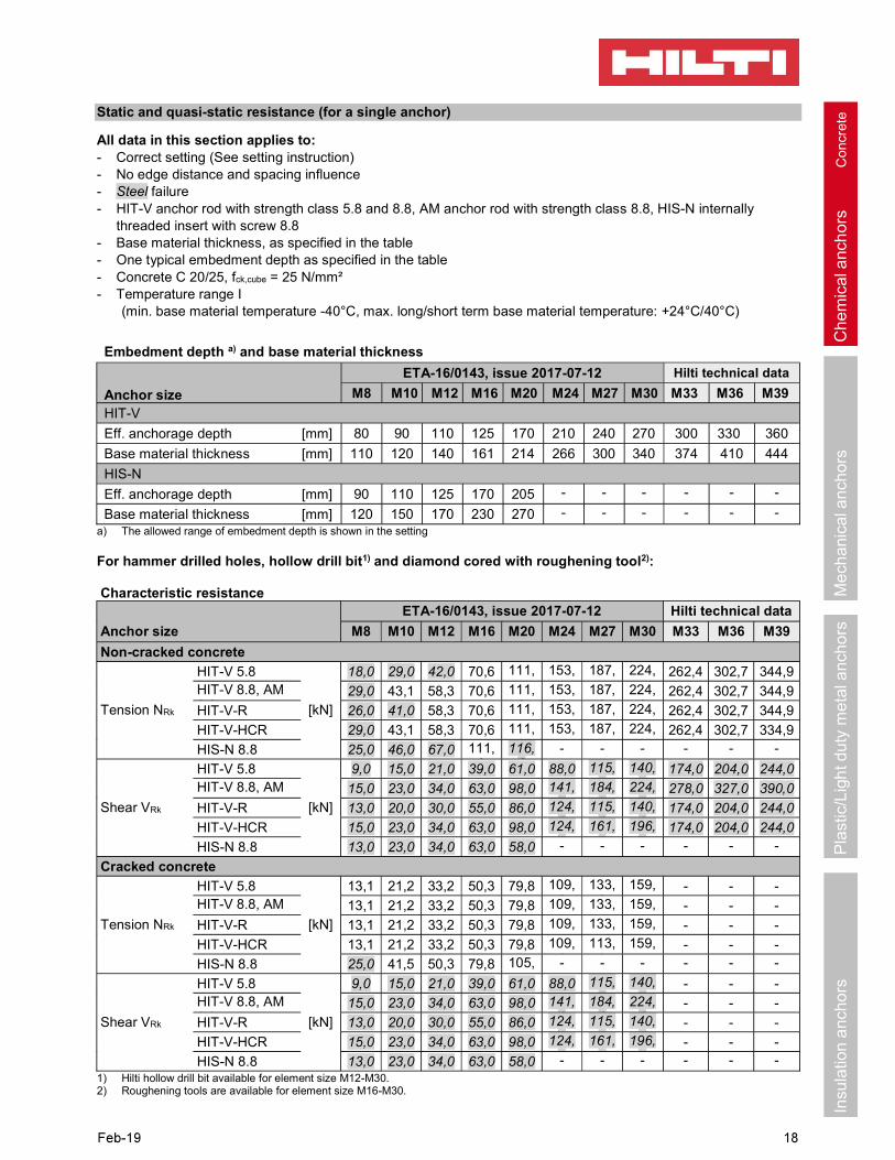
Static and quasi-static resistance (for a single anchor)
All data in this section applies to:- Correct setting (See setting instruction)- No edge distance and spacing influence- Steel failure- HIT-V anchor rod with strength class 5.8 and 8.8, AM anchor rod with strength class 8.8, HIS-N internally
threaded insert with screw 8.8- Base material thickness, as specified in the table- One typical embedment depth as specified in the table- Concrete C 20/25, fck,cube = 25 N/mm²- Temperature range I
(min. base material temperature -40°C, max. long/short term base material temperature: +24°C/40°C)
a) The allowed range of embedment depth is shown in the setting
For hammer drilled holes, hollow drill bit1) and diamond cored with roughening tool2):
Characteristic resistance
Anchor size
ETA-16/0143, issue 2017-07-12 Hilti technical data
M8 M10 M12 M16 M20 M24 M27 M30 M33 M36 M39
Non-cracked concrete
Tension NRk
HIT-V 5.8
[kN]
18,0 29,0 42,0 70,6 111,9
153,7
187,8
224,0
262,4 302,7 344,9HIT-V 8.8, AM 8.8
29,0 43,1 58,3 70,6 111,9
153,7
187,8
224,0
262,4 302,7 344,9
HIT-V-R 26,0 41,0 58,3 70,6 111,9
153,7
187,8
224,0
262,4 302,7 344,9
HIT-V-HCR 29,0 43,1 58,3 70,6 111,9
153,7
187,8
224,0
262,4 302,7 334,9
HIS-N 8.8 25,0 46,0 67,0 111,9
116,0
- - - - - -
Shear VRk
HIT-V 5.8
[kN]
9,0 15,0 21,0 39,0 61,0 88,0 115,0
140,0
174,0 204,0 244,0HIT-V 8.8, AM 8.8
15,0 23,0 34,0 63,0 98,0 141,0
184,0
224,0
278,0 327,0 390,0
HIT-V-R 13,0 20,0 30,0 55,0 86,0 124,0
115,0
140,0
174,0 204,0 244,0
HIT-V-HCR 15,0 23,0 34,0 63,0 98,0 124,0
161,0
196,0
174,0 204,0 244,0
HIS-N 8.8 13,0 23,0 34,0 63,0 58,0 - - - - - -
Cracked concrete
Tension NRk
HIT-V 5.8
[kN]
13,1 21,2 33,2 50,3 79,8 109,6
133,9
159, - - -HIT-V 8.8, AM 8.8
13,1 21,2 33,2 50,3 79,8 109,6
133,9
159, - - -
HIT-V-R 13,1 21,2 33,2 50,3 79,8 109,6
133,9
159, - - -
HIT-V-HCR 13,1 21,2 33,2 50,3 79,8 109,6
113,9
159, - - -
HIS-N 8.8 25,0 41,5 50,3 79,8 105,7
- - - - - -
Shear VRk
HIT-V 5.8
[kN]
9,0 15,0 21,0 39,0 61,0 88,0 115,0
140,0
- - -HIT-V 8.8, AM 8.8
15,0 23,0 34,0 63,0 98,0 141,0
184,0
224,0
- - -
HIT-V-R 13,0 20,0 30,0 55,0 86,0 124,0
115,0
140,0
- - -
HIT-V-HCR 15,0 23,0 34,0 63,0 98,0 124,0
161,0
196,0
- - -
HIS-N 8.8 13,0 23,0 34,0 63,0 58,0 - - - - - -1) Hilti hollow drill bit available for element size M12-M30.2) Roughening tools are available for element size M16-M30.
Embedment depth a) and base material thickness
Anchor size
ETA-16/0143, issue 2017-07-12 Hilti technical data
M8 M10 M12 M16 M20 M24 M27 M30 M33 M36 M39
HIT-V
Eff. anchorage depth [mm] 80 90 110 125 170 210 240 270 300 330 360
Base material thickness [mm] 110 120 140 161 214 266 300 340 374 410 444
HIS-N
Eff. anchorage depth [mm] 90 110 125 170 205 - - - - - -
Base material thickness [mm] 120 150 170 230 270 - - - - - -
Ch
em
ica
lanc
hor
sC
onc
rete
Me
cha
nica
lan
chor
sP
last
ic/L
igh
t du
tym
eta
l anc
ho
rsIn
sula
tion
anc
ho
rs
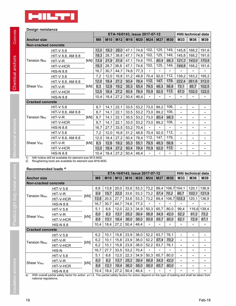
Design resistance
Anchor size
ETA-16/0143, issue 2017-07-12 Hilti technical data
M8 M10 M12 M16 M20 M24 M27 M30 M33 M36 M39
Non-cracked concrete
Tension NRd
HIT-V 5.8
[kN]
12,0 19,3 28,0 47,1 74,6 102,5
125,2
149,4
145,8 168,2 191,6
HIT-V 8.8, AM 8.8 19,3 28,7 38,8 47,1 74,6 102,5
125,2
149,4
145,8 168,2 191,6
HIT-V-R 13,9 21,9 31,6 47,1 74,6 102,5
80,4 98,3 121,3 143,0 170,6
HIT-V-HCR 19,3 28,7 38,8 47,1 74,6 102,5
125,2
149,4
144,6 168,2 191,6
HIS-N 8.8 16,7 30,7 44,7 74,6 77,3 - - - - - -
Shear VRd
HIT-V 5.8
[kN]
7,2 12,0 16,8 31,2 48,8 70,4 92,0 112,0
139,2 163,2 195,2
HIT-V 8.8, AM 8.8 12,0 18,4 27,2 50,4 78,4 112,8
147,2
179,2
222,4 261,6 312,0
HIT-V-R 8,3 12,8 19,2 35,3 55,4 79,5 48,3 58,8 73,1 85,7 102,5
HIT-V-HCR 12,0 18,4 27,2 50,4 78,4 70,9 92,0 112,0
87,0 102,0 122,0
HIS-N 8.8 10,4 18,4 27,2 50,4 46,4 - - - - - -
Cracked concrete
Tension NRd
HIT-V 5.8
[kN]
8,7 14,1 22,1 33,5 53,2 73,0 89,2 106,5
- - -
HIT-V 8.8, AM 8.8 8,7 14,1 22,1 33,5 53,2 73,0 89,2 106,5
- - -
HIT-V-R 8,7 14,1 22,1 35,5 53,2 73,0 80,4 98,3 - - -
HIT-V-HCR 8,7 14,1 22,1 33,5 53,2 73,0 89,2 106,5
- - -
HIS-N 8.8 16,7 27,7 33,5 53,2 70,4 - - - - - -
Shear VRd
HIT-V 5.8
[kN]
7,2 12,0 16,8 31,2 48,8 70,4 92,0 112,0
- - -
HIT-V 8.8, AM 8.8 12,0 18,4 27,2 50,4 78,4 112,8
147,2
179,2
- - -
HIT-V-R 8,3 12,8 19,2 35,3 55,1 79,5 48,3 58,8 - - -
HIT-V-HCR 12,0 18,4 27,2 50,4 78,4 70,9 92,0 112,0
- - -
HIS-N 8.8 10,4 18,4 27,2 50,4 46,4 - - - - - -1) Hilti hollow drill bit available for element size M12-M30.2) Roughening tools are available for element size M16-M30.
Recommended loads a)
Anchor sizeETA-16/0143, issue 2017-07-12 Hilti technical data
M8 M10 M12 M16 M20 M24 M27 M30 M33 M36 M39
Non-cracked concrete
Tension NRec
HIT-V 5.8
[kN]
8,6 13,8 20,0 33,6 53,3 73,2 89,4 106,7 104,1 120,1 136,9
HIT-V-R 9,9 15,7 22,5 33,6 53,3 73,2 57,4 70,2 86,7 102,1 121,9
HIT-V-HCR 13,8 20,5 27,7 33,6 53,3 73,2 89,4 106,7 103,3 120,1 136,9
HIS-N 8.8 16,7 30,7 44,7 74,6 77,3 - - - - - -
Shear VRec
HIT-V 5.8
[kN]
5,1 8,6 12,0 22,3 34,9 50,3 65,7 80,0 99,4 116,6 139,4
HIT-V-R 6,0 9,2 13,7 25,2 39,4 56,8 34,5 42,0 52,2 61,2 73,2
HIT-V-HCR 8,6 13,1 19,4 36,0 56,0 50,6 65,7 80,0 62,1 72,9 87,1
HIS-N 8.8 10,4 18,4 27,2 50,4 46,4 - - - - - -
Cracked concrete
Tension NRec
HIT-V 5.8
[kN]
6,2 10,1 15,8 23,9 38,0 52,2 63,7 76,1 - - -
HIT-V-R 6,2 10,1 15,8 23,9 38,0 52,2 57,4 70,2 - - -
HIT-V-HCR 6,2 10,1 15,8 23,9 38,0 52,2 63,7 76,1 - - -
HIS-N 16,7 27,7 33,5 53,2 70,4 - - - - - -
Shear VRec
HIT-V 5.8
[kN]
5,1 8,6 12,0 22,3 34,9 50,3 65,7 80,0 - - -
HIT-V-R 6,0 9,2 13,7 25,2 39,4 56,8 34,5 42,0 - - -
HIT-V-HCR 8,6 13,1 19,4 36,0 56,0 56,0 65,7 80,0 - - -
HIS-N 8.8 10,4 18,4 27,2 50,4 46,4 - - - - - -a) With overall partial safety factor for action =1,4. The partial safety factors for action depend on the type of loading and shall be taken from
national regulations.

Ch
em
ica
lanc
hor
sC
onc
rete
Me
cha
nica
lan
chor
sP
last
ic/L
igh
t du
tym
eta
l anc
ho
rsIn
sula
tion
anc
ho
rs
For diamond drilling a):
Characteristic resistanceAnchor size M8 M10 M12 M16 M20 M24 M27 M30
Non-cracked concrete
Tension NRkHIT-V 5.8 [kN]
18,0 29,0 42,0 70,6 111,9 153,7 187,8 224,0
HIT-V 8.8, AM 8.8 24,1 33,9 49,8 70,6 111,9 153,7 187,8 224,0
Shear VRkHIT-V 5.8 [kN]
9,0 15,0 21,0 39,0 61,0 88,0 115,0 140,0
HIT-V 8.8, AM 8.8 15,0 23,0 34,0 63,0 98,0 141,0 184,0 224,0a) No data for HIS-N when diamond coring without roughening tools.
Design resistanceAnchor size M8 M10 M12 M16 M20 M24 M27 M30
Non-cracked concrete
Tension NRdHIT-V 5.8
[kN]12,0 18,8 27,6 33,6 53,3 73,2 89,4 106,7
HIT-V 8.8, AM 8.8 13,4 18,8 27,6 33,6 53,3 73,2 89,4 106,7
Shear VRdHIT-V 5.8
[kN]7,2 12,0 16,8 31,2 48,8 70,4 92,0 112,0
HIT-V 8.8, AM 8.8 12,0 18,4 27,2 50,4 78,4 112,8 147,2 179,2a) No data for HIS-N when diamond coring without roughening tools.
Recommended loads b)
Anchor size M8 M10 M12 M16 M20 M24 M27 M30
Non-cracked concrete
Tensile NRec HIT-V 5.8 [kN] 8,6 13,5 19,7 24,0 38,1 52,3 63,9 76,2
Shear VRec HIT-V 5.8 [kN] 5,1 8,6 12,0 22,3 34,9 50,3 65,7 80,0a) No data for HIS-N when diamond coring without roughening tools.b) With overall partial safety factor for action =1,4. The partial safety factors for action depend on the type of loading and shall be taken from
national regulations.

Ch
em
ica
lanc
hor
sC
onc
rete
Me
cha
nica
lan
chor
sP
last
ic/L
igh
t du
tym
eta
l anc
ho
rsIn
sula
tion
anc
ho
rs
Seismic resistance
All data in this section applies to:- Correct setting (See setting instruction)- No edge distance and spacing influence- Steel failure- Anchor HIT-V strength class 8.8, anchor AM 8.8- Base material thickness, as specified in the table- One typical embedment depth as specified in the table- Concrete C 20/25, fck,cube = 25 N/mm²- Temperature range I
(min. base material temperature -40°C, max. long/short term base material temperature: +24°C/40°C)- gap=1,0 (using Hilti seismic filling set)
a) C2 seismic approval only available for HIT-V rods.
For hammer drilled holes, hollow drill bit and diamond cored with roughening tool:
Characteristic resistance in case of seismic performance category C2 using Hilti seismic filling setAnchor size M8 M10 M12 M16 M20 M24 M27 M30
Tensile NRk HIT-V 8.8, AM 8.8 [kN] - - - 34,6 57,7 80,8 - -
Shear VRk
HIT-V 8.8, AM 8.8[kN]
- - - 46,0 77,0 103,0 - -
HIT-V-F 8.8AM-HDG 8.8
- - - 30,0 46,0 66,0 - -
Design resistance in case of seismic performance category C2 using Hilti seismic filling setAnchor size M8 M10 M12 M16 M20 M24 M27 M30
Tensile NRd HIT-V 8.8, AM 8.8 [kN] - - - 23,0 38,5 53,8 - -
Shear VRd
HIT-V 8.8, AM 8.8[kN]
- - - 36,8 61,6 82,4 - -
HIT-V-F 8.8AM-HDG 8.8
- - - 24,0 36,8 52,8 - -
For hammer drilled holes and hammer drilled holes with Hilti hollow drill bit:
Characteristic resistance in case of seismic performance category C1Anchor size M8 M10 M12 M16 M20 M24 M27 M30
Tensile NRk HIT-V 8.8, AM 8.8
[kN]12,1 19,8 32,8 42,8 67,8 93,1 113,8 135,8
HIS-N 8.8 25,0 35,3 42,8 67,8 89,8 - - -
Shear VRkHIT-V 8.8, AM 8.8
[kN]15,0 23,0 34,0 63,0 98,0 141,0 184,0 224,0
HIS-N 8.8 9,0 16,0 24,0 44,0 41,0 - - -
Embedment depth and base material thickness for seismic C2 a) and C1
Anchor size M8 M10 M12 M16 M20 M24 M27 M30
HIT-V
Eff. Anchorage depth [mm] 80 90 110 125 170 210 240 270
Base material thickness [mm] 110 120 140 165 220 270 300 340
HIS-N
Eff. Anchorage depth [mm] 90 110 125 170 205 - - -
Base material thickness [mm] 120 146 169 226 269 - - -

Ch
em
ica
lanc
hor
sC
onc
rete
Me
cha
nica
lan
chor
sP
last
ic/L
igh
t du
tym
eta
l anc
ho
rsIn
sula
tion
anc
ho
rs
Design resistance in case of seismic performance category C1Anchor size M8 M10 M12 M16 M20 M24 M27 M30
Tensile NRdHIT-V 8.8, AM 8.8
[kN]8,0 13,2 21,8 28,5 45,2 62,1 75,9 90,5
HIS-N 8.8 16,7 23,5 28,5 45,2 59,9 - - -
Shear VRdHIT-V 8.8, AM 8.8
[kN]12,0 18,4 27,2 50,4 78,4 112,8 147,2 179,2
HIS-N 8.8 7,2 12,8 19,2 35,2 32,8 - - -
Materials
Mechanical properties for HIT-V
Anchor sizeETA-16/0143, issue 2017-07-12
Hilti Technical data
M8 M10 M12 M16 M20 M24 M27 M30 M33 M36 M39
Nominal tensile strength fuk
HIT-V 5.8(F)
[N/mm²]
500 500 500 500 500 500 500 500 500 500 500
HIT-V 8.8(F) 800 800 800 800 800 800 800 800 800 800 800
AM 8.8(HDG) 800 800 800 800 800 800 800 800 800 800 800
HIT-V-R 700 700 700 700 700 700 500 500 500 500 500
HIT-V-HCR 800 800 800 800 800 700 700 700 500 500 500
Yield strength fyk
HIT-V 5.8(F)
[N/mm²]
400 400 400 400 400 400 400 400 400 400 400
HIT-V 8.8(F) 640 640 640 640 640 640 640 640 640 640 640
AM 8.8(HDG) 640 640 640 640 640 640 640 640 640 640 640
HIT-V-R 450 450 450 450 450 450 210 210 210 210 210
HIT-V-HCR 640 640 640 640 640 400 400 400 250 250 250
Stressed cross-section As
HIT-V AM 8.8 [mm²] 36,6 58,0 84,3 157 245 353 459 561 694 817 976
Moment of resistance W
HIT-V AM 8.8 [mm³] 31,2 62,3 109 277 541 935 1387 1874 2579 3294 4301
Mechanical properties for HIS-N
Anchor sizeETA-16/0143, issue 2017-07-12
M8 M10 M12 M16 M20
Nominal tensile strength fuk
HIS-N
[N/mm²]
490 490 460 460 460
Screw 8.8 800 800 800 800 800
HIS-RN 700 700 700 700 700
Screw A4-70 700 700 700 700 700
Yield strength fyk
HIS-N
[N/mm²]
410 410 375 375 375
Screw 8.8 640 640 640 640 640
HIS-RN 350 350 350 350 350
Screw A4-70 450 450 450 450 450
Stressed cross-section As
HIS-(R)N[mm²]
51,5 108,0 169,1 256,1 237,6
Screw 36,6 58 84,3 157 245
Moment of resistance W
HIS-(R)N[mm³]
145 430 840 1595 1543
Screw 31,2 62,3 109 277 541

Ch
em
ica
lanc
hor
sC
onc
rete
Me
cha
nica
lan
chor
sP
last
ic/L
igh
t du
tym
eta
l anc
ho
rsIn
sula
tion
anc
ho
rs
Material quality for HIT-V
Part Material
Zinc coated steel
Threaded rod,HIT-V 5.8 (F)
Strength class 5.8; Elongation at fracture A5 > 8% ductileElectroplated zinc coated 5 m; (F) hot dip 45 m
Threaded rod,HIT-V 8.8 (F)
Strength class 8.8; Elongation at fracture A5 > 12% ductileElectroplated zinc coated 5 m 45 m
Hilti Meter rod,AM 8.8 (HDG)
Strength class 8.8; Elongation at fracture A5 > 12% ductileElectroplated zinc coated 5 m
45 m
Washer Electroplated zinc coated m, hot dip galvanized m
NutStrength class of nut adapted to strength class of threaded rod.Electroplated zinc coated 5 m, hot dip galvanized m
Stainless Steel
Threaded rod,HIT-V-R
Strength class 70 for M24 and strength class 50 for > M24; Elongation at fracture A5 > 8% ductileStainless steel 1.4401; 1.4404; 1.4578; 1.4571; 1.4439; 1.4362
Washer Stainless steel 1.4401, 1.4404, 1.4578, 1.4571, 1.4439, 1.4362 EN 10088-1:2014
Nut Stainless steel 1.4401, 1.4404, 1.4578, 1.4571, 1.4439, 1.4362 EN 10088-1:2014
High corrosion resistant steel
Threaded rod,HIT-V-HCR
Strength class 80 for M20 and class 70 for > M20, Elongation at fracture A5 > 8% ductileHigh corrosion resistance steel 1.4529; 1.4565;
Washer High corrosion resistant steel 1.4529, 1.4565 EN 10088-1:2014
Nut High corrosion resistant steel 1.4529, 1.4565 EN 10088-1:2014
Material quality for HIS-N
Part Material
HIS-NInternal threaded sleeve
C-steel 1.0718; Steel galvanized 5 µm
Screw 8.8 Strength class 8.8, A5 > 8 % Ductile; Steel galvanized 5 µm
HIS-RN
Internal threaded sleeve
Stainless steel 1.4401,1.4571
Screw 70Strength class 70, A5 > 8 % DuctileStainless steel 1.4401; 1.4404, 1.4578; 1.4571; 1.4439; 1.4362
Setting information
Installation temperature-5°C to +40°C
Service temperature rangeHilti HIT-RE 500 V3 injection mortar may be applied in the temperature ranges given below. An elevated base material temperature may lead to a reduction of the design bond resistance.
Temperature rangeBase material temperature
Max. long term base material temperature
Max. short term base material temperature
Temperature range I -40 °C to +40 °C +24 °C +40 °C
Temperature range II -40 °C to +70 °C +43 °C +70 °C

Ch
em
ica
lanc
hor
sC
onc
rete
Me
cha
nica
lan
chor
sP
last
ic/L
igh
t du
tym
eta
l anc
ho
rsIn
sula
tion
anc
ho
rs
Max short term base material temperatureShort-term elevated base material temperatures are those that occur over brief intervals, e.g. as a result of diurnal cycling.Max long term base material temperatureLong-term elevated base material temperatures are roughly constant over significant periods of time.
Working time and curing time
Temperature of the base materialT
Working time twork
Minimum curing time tcure
1)
-5 °C to -1 °C 2 h 168 h
0 °C to 4 °C 2 h 48 h
5 °C to 9 °C 2 h 24 h
10 °C to 14 °C 1,5 h 16 h
15 °C to 19 °C 1 h 12 h
20 °C to 24 °C 30 min 7 h
25 °C to 29 °C 20 min 6 h
30 °C to 34 °C 15 min 5 h
35 °C to 39 °C 12 min 4,5 h
40 °C 10 min 4 h1) The curing time data are valid for dry base material only. In wet base material, the curing times must be doubled.
Setting details for HIT-V
Anchor size
ETA-16/0143, issue 2017-07-12Hilti Technical
dataM8 M10 M12 M16 M20 M24 M27 M30 M33 M36 M39
Nominal diameter of drill bit
d0 [mm] 10 12 14 18 22 28 30 35 37 40 42
Effective anchorage and drill hole depth range a)
hef,min [mm] 60 60 70 80 90 96 108 120 132 144 156
hef,max [mm] 160 200 240 320 400 480 540 600 660 720 780Minimum base material thickness
hmin [mm]hef +30 mm
hef + 2 d0
Max. torque moment Tmax [mm] 10 20 40 80 150 200 270 300 330 360 390
Minimum spacing smin [mm] 40 50 60 75 90 115 120 140 165 180 195
Min. edge distance cmin [mm] 40 45 45 50 55 60 75 80 165 180 195Critical spacing for splitting failure
scr,sp [mm] 2 ccr,sp
Critical edge distance for splitting failure b) ccr,sp [mm]
1,0 hef for h / hef
4,6 hef - 1,8 h for 2,0 > h / hef > 1,3
2,26 hef for h / hef
Critical spacing for concrete cone failure
scr,N [mm] 2 ccr,N
Critical edge distance for concrete cone failurec) ccr,N [mm] 1,5 hef

Ch
em
ica
lanc
hor
sC
onc
rete
Me
cha
nica
lan
chor
sP
last
ic/L
igh
t du
tym
eta
l anc
ho
rsIn
sula
tion
anc
ho
rs
Setting details for HIS-N
Anchor size M8 M10 M12 M16 M20Nominal diameter of drill bit
d0 [mm] 14 18 22 28 32
Diameter of element d [mm] 12,5 16,5 20,5 25,4 27,6Effective anchorage and drill hole depth
hef [mm] 90 110 125 170 205
Minimum base material thickness
hmin [mm] 120 150 170 230 270
Diameter of clearance hole in the fixture
df [mm] 9 12 14 18 22
Thread engagement length; min - max
hs [mm] 8-20 10-25 12-30 16-40 20-50
Minimum spacing smin [mm] 60 70 90 115 130Minimum edge distance cmin [mm] 40 45 55 65 90Critical spacing for splitting failure
scr,sp [mm] 2 ccr,sp
Critical edge distance for splitting failure b) ccr,sp [mm]
1,0 hef for h / hef
4,6 hef 1,8 h for 2,0 > h / hef > 1,3
2,26 hef for h / hef
Critical spacing for concrete cone failure
scr,N [mm] 2 ccr,N
Critical edge distance for concrete cone failure c) ccr,N [mm] 1,5 hef
Max. torque moment a) Tmax [Nm] 10 20 40 80 150For spacing (edge distance) smaller than critical spacing (critical edge distance) the design loads have to be reduced.a) hef,min hef ef,max (hef: embedment depth)b) h: base material thickness (h hmin)c) The critical edge distance for concrete cone failure depends on the embedment depth hef and the design bond
resistance. The simplified formula given in this table is on the save side.
Installation equipmentAnchor size M8 M10 M12 M16 M20 M24 M27 M30 M36 M39
Rotary hammerHIT-V TE 2 TE 16 TE 40 TE 80
Not available from Hilti
HIS-N TE 2 TE 16 TE 40 TE 80 -
Other toolscompressed air gun, set of cleaning brushes, dispenser
roughening tools TE-YRT -
AdditionalHilti recommended tools
DD EC- a) -
a) For anchors in diamond drilled holes load values for combined pull-out and concrete cone resistance have to be reduced
Ch
em
ica
lanc
hor
sC
onc
rete
Me
cha
nica
lan
chor
sP
last
ic/L
igh
t du
tym
eta
l anc
ho
rsIn
sula
tion
anc
ho
rs
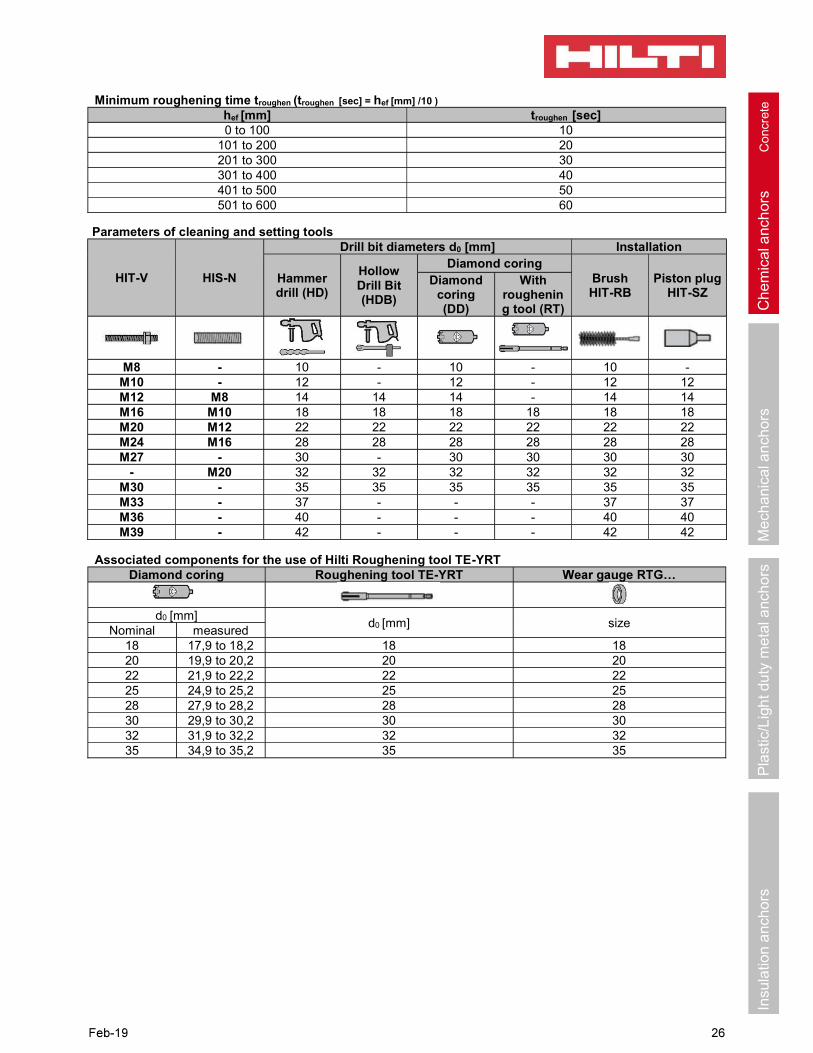
Minimum roughening time troughen (troughen [sec] = hef [mm] /10 )
hef [mm] troughen [sec]0 to 100 10
101 to 200 20201 to 300 30301 to 400 40401 to 500 50501 to 600 60
Parameters of cleaning and setting tools
HIT-V HIS-N
Drill bit diameters d0 [mm] Installation
Hammer drill (HD)
Hollow Drill Bit (HDB)
Diamond coringBrushHIT-RB
Piston plugHIT-SZ
Diamond coring(DD)
With roughening tool (RT)
M8 - 10 - 10 - 10 -M10 - 12 - 12 - 12 12M12 M8 14 14 14 - 14 14M16 M10 18 18 18 18 18 18M20 M12 22 22 22 22 22 22M24 M16 28 28 28 28 28 28M27 - 30 - 30 30 30 30
- M20 32 32 32 32 32 32M30 - 35 35 35 35 35 35M33 - 37 - - - 37 37M36 - 40 - - - 40 40M39 - 42 - - - 42 42
Associated components for the use of Hilti Roughening tool TE-YRTDiamond coring Roughening tool TE-YRT
d0 [mm]d0 [mm] size
Nominal measured18 17,9 to 18,2 18 1820 19,9 to 20,2 20 2022 21,9 to 22,2 22 2225 24,9 to 25,2 25 2528 27,9 to 28,2 28 2830 29,9 to 30,2 30 3032 31,9 to 32,2 32 3235 34,9 to 35,2 35 35

Setting instructions
*For detailed information on installation see instruction for use given with the package of the product.
Safety regulations.
Review the Material Safety Data Sheet (MSDS) before use for proper and safe handling! Wear well-fitting protective goggles and protective gloves when working with Hilti HIT-RE 500 V3.
Drilling
Hammer drilled hole
For dry and wet concrete and installation in flooded holes (no sea water).
Hammer drilled hole with Hollow Drilled Bit (HDB)
No cleaning required.For dry and wet concrete, only.
Diamond CoringFor dry and wet concrete, only.
Diamond Coring + Roughening ToolFor dry and wet concrete only.Before roughening, the borehole needs to be dry.
Cleaning ( Inadequate hole cleaning=poor load values.)
Hammer Drilling:
Compressed air cleaning (CAC)For all drill hole diameters d0 and all drill hole depths h0.
Hammer drilling:
Cleaning for under water:
For all bore hole diameters d0 and all bore hole depth h0.

Hammer drilled flooded holes and diamond cored holes:
Compressed air cleaning (CAC)for all drill hole diameters d0 and drill hole depths h0.
Diamond cored holes with Hilti roughening tool:
Compressed air cleaning (CAC)for all drill hole diameters d0 and drill hole depths h0 .
Injection preparation
Injection system preparation.
Injection method for drill hole depth
hef 250 mm.
Injection method for drill hole depth
hef > 250mm.
Injection method for overhead application.

Ch
em
ica
lanc
hor
sC
onc
rete
Me
cha
nica
lan
chor
sP
last
ic/L
igh
t du
tym
eta
l anc
ho
rsIn
sula
tion
anc
ho
rs
Setting the element
Setting element, observe working time work ,
Loading the anchor after required curing time tcure the anchor can be loaded. The applied installation torque shall not exceed Tmax.
Setting element for overhead applications, observe work
Loading the anchor after required curing time tcure the anchor can be loaded. The applied installation torque shall not exceed Tmax.