ft51a installation guide - brtchip.com · application note an_352 ft51a installation guide version...
TRANSCRIPT

Use of FTDI devices in life support and/or safety applications is entirely at the user’s risk, and the user agrees to defend, indemnify and hold FTDI harmless from any and all damages, claims, suits
or expense resulting from such use.
Future Technology Devices International Limited (FTDI) Unit 1, 2 Seaward Place, Glasgow G41 1HH, United Kingdom Tel.: +44 (0) 141 429 2777 Fax: + 44 (0) 141 429 2758
Web Site: http://ftdichip.com Copyright © 2015 Future Technology Devices International Limited
Application Note
AN_352
FT51A Installation Guide
Version 1.2
Issue Date: 2015-11-24
This document provides a guide for configuring the FT51A development environment; using firmware libraries supplied by FTDI; and writing applications.

Application Note
AN_352 FT51A Installation Guide Version 1.2
Document Reference No.: FT_001135 Clearance No.: FTDI# 429
2 Product Page Document Feedback Copyright © 2015 Future Technology Devices International Limited
Table of Contents
1 Introduction .................................................................................................................................... 4
1.1 Overview ................................................................................................................................. 4
1.2 Features .................................................................................................................................. 4
1.3 Scope ....................................................................................................................................... 4
2 Compilation Environment ............................................................................................................... 5
2.1 Installation .............................................................................................................................. 5
2.1.1 Eclipse ............................................................................................................................. 6
2.1.2 SDCC ................................................................................................................................ 7
2.1.3 GnuWin32 ....................................................................................................................... 7
2.1.4 Configuring Eclipse .......................................................................................................... 7
2.2 FTDI Tools ................................................................................................................................ 9
2.2.1 Debugger ft51gdb.exe..................................................................................................... 9
2.2.2 Programmer ft51prg.exe............................................................................................... 10
2.2.3 String modifier ft51str.exe ............................................................................................ 11
2.3 Using SDCC ............................................................................................................................ 11
2.3.1 SDCC Restrictions .......................................................................................................... 11
2.3.2 SDCC File Types ............................................................................................................. 12
2.4 Making an Eclipse Project ..................................................................................................... 12
2.4.1 Create an Empty Project ............................................................................................... 12
2.4.2 Create a Template Project ............................................................................................ 13
2.4.3 Modifying the Project ................................................................................................... 15
2.4.4 Adding Source Files and Header Files ........................................................................... 17
2.4.5 Selecting the Language ................................................................................................. 17
2.4.6 Compiling a Project ....................................................................................................... 18
2.5 Adding an Eclipse Debug Configuration ................................................................................ 18
2.5.1 Modifying the Main Tab ................................................................................................ 19
2.5.2 Modifying the Debugger Tab ........................................................................................ 21
2.5.3 Debugging Hardware .................................................................................................... 22
2.5.4 Debugging Views ........................................................................................................... 22

Application Note
AN_352 FT51A Installation Guide Version 1.2
Document Reference No.: FT_001135 Clearance No.: FTDI# 429
3 Product Page Document Feedback Copyright © 2015 Future Technology Devices International Limited
2.5.5 Debugging Restrictions ................................................................................................. 24
2.5.6 Debugging SDCC Compiled Applications ....................................................................... 24
2.6 Adding an Eclipse Run Configuration .................................................................................... 24
2.7 Programming a Device from Eclipse ..................................................................................... 26
3 SDK File Structure.......................................................................................................................... 28
3.1 Uninstallation ........................................................................................................................ 28
4 Contact Information ...................................................................................................................... 29
Appendix A – References ...................................................................................................................... 30
Document References ....................................................................................................................... 30
Acronyms and Abbreviations ............................................................................................................ 30
Appendix B – List of Tables & Figures ................................................................................................... 31
List of Tables ..................................................................................................................................... 31
List of Figures .................................................................................................................................... 31
Appendix C – Revision History .............................................................................................................. 32

Application Note
AN_352 FT51A Installation Guide Version 1.2
Document Reference No.: FT_001135 Clearance No.: FTDI# 429
4 Product Page Document Feedback Copyright © 2015 Future Technology Devices International Limited
1 Introduction
This guide documents the installation and use of the tools for compiling, programming and debugging code on an FT51A.
1.1 Overview
The FT51A series of devices provide a USB device interface, a built-in USB hub and an 8051 compatible microcontroller. The 8051 compatible component is referred to as the ‘core’.
There is 16kB of program storage in MTP (Multiple Time Programmable) memory, 16kB of Shadow RAM (from where code is run), 8kB of data RAM and 128 bytes of internal RAM.
Details of the device are fully documented in the FT51A Series Datasheets.
Additionally there are the following hardware interfaces:
- GPIO - UART - PWM - SPI Master and Slave - I2C Master and Slave - FT245 Parallel FIFO - ADC
- Additional Timers
The FT51A has an internal USB Full Speed device controller that is register compatible with an FT122. An internal on-chip USB hub can optionally be enabled to allow a single downstream port from the FT51A.
1.2 Features
The programming environment for the FT51A has the following features:
- Open source SDCC compiler – licensed under the GPL. - GDB-like debugger – licensed under the GPL. - Eclipse IDE plugin for FT51A compilation using SDCC compiler – licensed under the EPL. - Eclipse IDE uses C/C++ personality and standard C/C++ Application debugging
configurations.
1.3 Scope
The guide is intended for developers who are creating applications, extending FTDI provided
applications or implementing example applications for the FT51A.
In the reference of the FT51A, an “application” refers to firmware that runs on the FT51A; “libraries” are source code provided by FTDI to help users access specific hardware features of the chip.
The FT51A Tools are currently only available for Microsoft Windows platforms and are tested on Windows 7 and later versions.

Application Note
AN_352 FT51A Installation Guide Version 1.2
Document Reference No.: FT_001135 Clearance No.: FTDI# 429
5 Product Page Document Feedback Copyright © 2015 Future Technology Devices International Limited
2 Compilation Environment
FTDI provide an installer for the FT51A Toolchain. This will install tools, libraries, sample code, documentation and source code.
The toolchain will optionally install compilation tools, additional compilation utilities and the Eclipse development environment and a Java JRE.
The compilation tool required for building applications for the FT51A is SDCC (Small Device C Compiler). SDCC is a free open source compiler which can produce 8051 target code usable with
the 8051 compatible core of the FT51A.
Although applications can be compiled using SDCC on its own, the Eclipse IDE is recommended to provide a richer development and debugging environment whilst retaining SDCC functionality.
Eclipse is a free open source IDE which can be extended with plugins to provide an integrated project manager, code editor, build configurator and debugger. We recommend the CDT (C/C++
Development Tooling) version as it provides the general purpose environment for the FT51A upon which the FTDI plugins and programs have been developed to facilitate development.
Some additional compilation utilities from the GnuWin32 project are used to interface SDCC with Eclipse.
The FTDI FT51A tools complement SDCC and customize Eclipse to provide access to debugging features, build support and language support.
2.1 Installation
The FTDI FT51A Toolchain can be downloaded from the location in Table 2.1.
The installer will:
- Create an FTDI “toolchain” directory in the system Program Files area (normally “C:\Program Files (x86)\FTDI\FT51A Toolchain”).
- Install SDCC in the FT51A toolchain directory.
- Patch FTDI’s FT51A utilities into the SDCC installation. - (Optionally) Install “coreutils” and “make” components in the “External\GnuWin32”
directory within the toolchain directory. - (Optionally) Install an FT51A modified version of Eclipse into the “Toolchain\eclipse”
directory in the toolchain area. - Create a materials folder called “FTDI” in the user’s Documents area with a subfolder of
“FT51A”. A further subfolder is created with the version number of the toolchain to allow information from previous versions of toolchains to remain after an update.
- Install example code, documentation and Eclipse projects into the materials folder. - (Optionally) Launch an external Java installer. This is the latest version of the Java JRE
available at the time of building. This may require updating after installation is complete. - Update the PATH environment variable to include the required file paths.
FTDI’s tools included for the FT51A are:
- ft51gdb.exe: Debugger providing a gdb interface for Eclipse to access an FT51A target device for debugging.
- ft51prg.exe: FT51A Target programming tool which will write an application to the FT51A
Shadow RAM or MTP. - ft51str.exe: Application modification tool to change string descriptors for FTDI supplied
example code.
An Eclipse update site is installed enabling an existing version of Eclipse to be extended to incorporate the FT51A plugins. The instructions to install the plugins in Eclipse and configure Eclipse are in Section 2.1Error! Reference source not found..

Application Note
AN_352 FT51A Installation Guide Version 1.2
Document Reference No.: FT_001135 Clearance No.: FTDI# 429
6 Product Page Document Feedback Copyright © 2015 Future Technology Devices International Limited
Tool
Name
Tested
Version
s
URL
FT51A
Toolchain 1.0.0 http://www.ftdichip.com/Firmware/FT51ARegistration.htm
SDCC
3.5.0
(Window
s)
http://sdcc.sourceforge.net/
Eclipse
CDT MARS 1 http://www.eclipse.org/cdt/
Table 2.1 Development Tools
There are some optional compilation utilities that may be required to use some of the sample applications. Unix-like tools are used by Eclipse when using an “External Builder” using makefiles. The generated makefiles need “make”,“rm” and “printf” to work. If Eclipse is set to use an “Internal Builder” then these tools are not required, however example projects included in the SDK are set to build with the “External Builder”.
It is recommended that the versions of these supporting utilities from the GnuWin32 project be used.
The FTDI supplied tools are compiled using GCC from MinGW. The minimum MinGW “Basic Setup” installation will provide the required tools. MinGW is not installed by the FT51A SDK.
Tool
Name
Tested
Versions Required For URL
Make 3.81 Eclipse external builder and
supplied makefiles
http://gnuwin32.sourceforge.net/packages/make.htm
coreutils 5.3.0 http://gnuwin32.sourceforge.net/packages/coreutils.htm
MinGW latest
Compiling FTDI
Tools from
source
http://www.mingw.org/
Table 2.2 Additional Tools
This document does not discuss alternative methods of using the tools.
If the versions of SDCC, compilation utilities, Eclipse and Java JRE from the FT51A Toolchain are used then the instructions in the remainder of Section 2.1 are not required.
2.1.1 Eclipse
Follow instructions on the Eclipse CDT website to install Eclipse with the C/C++ Development Tooling. Note that Eclipse requires a Java runtime. Either a Java Runtime Environment (JRE) or Java Development Kit (JDK) is required.

Application Note
AN_352 FT51A Installation Guide Version 1.2
Document Reference No.: FT_001135 Clearance No.: FTDI# 429
7 Product Page Document Feedback Copyright © 2015 Future Technology Devices International Limited
Once installed, the “About Eclipse” dialog box will have the CDT Project logo as highlighted below in red (Figure 2.1 for an Eclipse Luna installation).
Figure 2.1 Installing CDT
2.1.2 SDCC
Download the SDCC tools from the location in Table 2.1and install. Make sure that the SDCC bin
directory is on the PATH environment variable for Windows (either on the current user’s path or the system path). It is also possible to add a path to an Eclipse workspace or project, please refer to the Eclipse documentation for this option.
2.1.3 GnuWin32
Download the make and coreutils packages from the location in Table 2.1. Ensure that the path where the utilities are installed is available on the current user’s path, system path, workspace path, or project path.
2.1.4 Configuring Eclipse
The following section describes how to configure Eclipse for the FT51A Toolchain.
2.1.4.1 Eclipse Plugin
An FT51A Eclipse plugin is provided. This customises Eclipse to: understand the language
constructs used in the SDCC compiler; help it recognize the output files of the SDCC compiler as an executable on FT51A devices; and allow it to build applications using the SDCC compiler parts.

Application Note
AN_352 FT51A Installation Guide Version 1.2
Document Reference No.: FT_001135 Clearance No.: FTDI# 429
8 Product Page Document Feedback Copyright © 2015 Future Technology Devices International Limited
The Eclipse plugin is based on the EclipseSDCC project (http://eclipse-sdcc.sourceforge.net/).
To install the plugin:
- Click “Help” and “Install new software”. - In the “Work with:” field type either the location of the eclipse plugins folder installed by
the FT51A Toolchain or the “Update Site” location on the FTDI website. The “Add…” button
will allow you to search for the FT51A Toolchain “materials” directory. Refer to Section 3 to identify the location of the eclipse plugins folder within the FT51A Toolchain directory.
- Select “FTDIchip FT51A Eclipse Plugins”. - Click “Next”, to install the plugin. Ignore the message about unsigned content. - Restart Eclipse.
Figure 2.2 Installing FTDI Plugin
The following customisations will be applied by the FTDIChip Plugin for FT51A.
Plugin Name ID
SDCC Managed Build Plug-in com.ftdichip.ft51.sdcc.build

Application Note
AN_352 FT51A Installation Guide Version 1.2
Document Reference No.: FT_001135 Clearance No.: FTDI# 429
9 Product Page Document Feedback Copyright © 2015 Future Technology Devices International Limited
SDCC Language Extension com.ftdichip.ft51.sdcc.language
SDCC Binary Parser com.ftdichip.ft51.sdcc.binaryparser
FT51A Code Templates com.ftdichip.ft51.templates
Table 2.3 FTDIChip Plugin for FT51A
Once restarted clicking on “Help”, “About Eclipse” then “Installation Details” will list “FTDIchip FT51A Resources” and the version number of the plugin as shown in Figure 2.4.
Figure 2.4 Eclipse Installed Software
2.2 FTDI Tools
The tools supplied by FTDI are distributed in the FT51A Toolchain as binaries with full source code. They complement the tools supplied by SDCC and allow programming and debugging through the
FTDI one-wire debugger interface.
The tools require GCC from MinGW to compile, but this is not necessary for normal operation. With the exception of ft51gdb.exe, they can be compiled with the supplied Eclipse projects. To compile ft51gdb.exe it must be added to the source directory for SDCC (in the debugger directory).
2.2.1 Debugger ft51gdb.exe
This tool is based on the sdcdb.exe tool that is provided with SDCC. It has been modified to replace the simulator with the FTDI one-wire debugging interface and uses the D2XX DLL from
FTDI to communicate with an external hardware debugger module available from FTDI.

Application Note
AN_352 FT51A Installation Guide Version 1.2
Document Reference No.: FT_001135 Clearance No.: FTDI# 429
10 Product Page Document Feedback Copyright © 2015 Future Technology Devices International Limited
It implements an MI and a command interface. MI is the method used by Eclipse to communicate with gdb. Not all gdb MI commands or options are implemented, only the ones directly used by Eclipse during debugging. The command interface is provided for convenience and does not implement a full set of features.
The command line parameters are as follows:
--directory=<src> Include a source code directory. This is not required unless ft51gdb.exe is required to provide source code output. Eclipse does not require this.
--interpreter mi Use the MI interpreter (Machine Instructions) on ft51gdb.exe. Omit this parameter to use the command interface.
--cd=<dir> Change into the directory before starting to process any instructions or load any code.
-p <device> Use the device name of an FTDI device of the debugging module for the FTDI one-wire debugging interface. If this is not set then the first FTDI device found which is connected to
and FT51A is used.
The final parameter is the name of a CDB file (an output of SDCC) that includes debugging information for the application to run on the target device.
There must be an accompanying IHX in the same directory and with the same name as the CDB file.
The following commands are supported in MI mode:
environment-cd environment-pwd environment-directory environment-path
exec-run exec-continue exec-next exec-step
exec-interrupt exec-jump gdb-exit gdb-set
gdb-show list-features list-target-features list-thread-groups
file-exec-and-symbols data-evaluate-
expression
data-list-register-
names
data-list-register-
values
data-read-memory-bytes
data-read-memory data-disassemble interpreter-exec
break-insert break-delete break-disable break-enable
break-list stack-info-depth stack-list-frames stack-list-locals
stack-list-arguments thread-info var-create var-update
var-set-format var-delete var-evaluate-expression
var-list-children
var-info-path-expression
target-detach target-disconnect source
enable-pretty-printing maintenance
Table 2.4 MI Commands Implemented in ft51gdb.exe
Please refer to the gdb documentation at https://sourceware.org/gdb/onlinedocs/gdb for more information on commands.
Not all parameters or response modes are enabled for all commands. Please inspect the source code for all supported parameters.
2.2.2 Programmer ft51prg.exe
The programmer tool is able to program the MTP or just the Shadow RAM of an FT51A device with an IHX file.

Application Note
AN_352 FT51A Installation Guide Version 1.2
Document Reference No.: FT_001135 Clearance No.: FTDI# 429
11 Product Page Document Feedback Copyright © 2015 Future Technology Devices International Limited
The command line parameters are as follows:
-s Program the Shadow RAM only. Do not commit the contents of the Shadow RAM to the MTP.
-g Run the code which has been programmed once the programming is complete.
-p <device> Use the device name of an FTDI device of the debugging module for the FTDI one-wire debugging interface. If this is not set then the first FTDI device found which is connected to
and FT51A is used.
The final parameter is the name of a IHX file (an output of SDCC) for the target device.
2.2.3 String modifier ft51str.exe
The string modification tool can change elements of a string descriptor table used to respond to USB Standard Requests for “GetDescriptor (String)”. The example code supplied by FTDI locates the string descriptor table at address 0x80 in code. The standard size of this table is 256 bytes.
The string table consists of a series of UNICODE strings each prefixed by 2 bytes of header data. The first byte is the length of the string inclusive of the 2 header bytes, the second is a byte indicating that this string is a string descriptor. Since this table has the same structure it can be modified by this utility, parameters are used to specify the location in code if it is different to the standard location.
The command line parameters are as follows:
-a Offset address to the start of the string table.
-o <filename> Optional output filename. If this is omitted then the output filename is <input_file>.mod.
-<n> The parameter is a decimal or hexadecimal number indicating the string descriptor number to modify. The string descriptor must already exist in the table as no new strings can be added by this tool.
The input file name is given as the final argument to the program. The standard output file name of the program is the full input file name appended with “.mod”.
The main use of this tool is to alter a firmware’s serial number or description making unique instances of applications to install on a number of FT51A based designs.
2.3 Using SDCC
There are no additional language extensions or requirements for the FT51A.
2.3.1 SDCC Restrictions
SDCC has some restrictions and design requirements which need to be followed for the FT51A.
The language extensions and restrictions are documented in the SDCC Manual but the more common points are reiterated here for clarity:
- Functions are not re-entrant unless they are explicitly marked as re-entrant. - Local variables and parameters are not generally stored or passed on the stack. Space is
reserved in internal or data memory for them. This can be reused (called overlapped)
when the function or variable is not in use. It also limits how some variables can be accessed during debugging. Some variables will appear not to update in the debugger or may even be shown as unavailable if the compiler has optimized them out completely.
- The memory address 0x0000 in external memory is sometimes used for global variables. Therefore pointer NULL checking may fail unexpectedly.
- The stack is very small so avoid deep call graphs. - SDCC aggressively caches data in the 8051 register space. This can cause problems with
non-atomic accesses.

Application Note
AN_352 FT51A Installation Guide Version 1.2
Document Reference No.: FT_001135 Clearance No.: FTDI# 429
12 Product Page Document Feedback Copyright © 2015 Future Technology Devices International Limited
2.3.2 SDCC File Types
IHX files are Intel Hex Files which are the output format of SDCC. These are converted into binary images to write into the FT51A program memory by the FTDI tools.
CDB files are output files from SDCC. They hold debugging information for the associated IHX file.
ROM files are binary images of the contents of the FT51A MTP memory. These are not produced by
SDCC but can be generated from the IHX files using a utility such as hex2bin (http://hex2bin.sourceforge.net). Generating a ROM can be useful to allow analysis of the layout of a program in memory, as IHX files do not need to be linear.
2.4 Making an Eclipse Project
To use SDCC with Eclipse, make a C Project in which all the settings for SDCC and the application are kept. This will make a directory in the workspace where source files can be kept and output files can be put.
2.4.1 Create an Empty Project
To create a new, empty project for the FT51A in Eclipse:
Select “New” then “Project…”. The dialog box in Figure 2.3 will appear. Expand “C/C++” and
choose “C Project”.
Figure 2.3 New Project Dialog
Click on “Next” to move to the C Project dialog in Figure 2.4.

Application Note
AN_352 FT51A Installation Guide Version 1.2
Document Reference No.: FT_001135 Clearance No.: FTDI# 429
13 Product Page Document Feedback Copyright © 2015 Future Technology Devices International Limited
Figure 2.4 C Project Dialog
Select “Executable, Empty Project” from the “Project type” box then “SDCC Tool Chain” from the
“Tool chains” box. This tells the Eclipse to use the FTDI FT51A plugins and SDCC to make the project output.
Click on “Finish” to make the project and add it to the current workspace.
2.4.2 Create a Template Project
There are template projects provided which will add source and header files.
The “Basic Project for SDCC” is part of the “com.ftdichip.ft51.sdcc.build” plugin and will create a project with a single source and a single header file based on a template. There are no library files
included although they may be added from the FT51A Toolchain directory at a later stage.
Figure 2.5 shows a workspace containing a Basic Project.

Application Note
AN_352 FT51A Installation Guide Version 1.2
Document Reference No.: FT_001135 Clearance No.: FTDI# 429
14 Product Page Document Feedback Copyright © 2015 Future Technology Devices International Limited
Figure 2.5 Basic Project for SDCC Workspace
Other template projects are available from the “com.ftdichip.ft51.templates” plugin which will
incorporate the FT51A libraries into the generated project.
The “USB HID Keyboard Project for FT51A” template allows the VID, PID and some USB configuration data to be entered. This is set in the source code of the files created in the folder “app”.
Figure 2.6 Basic Project for SDCC Workspace
Other template projects will have similar configuration pages which are accessed by clicking “Next” from the New C Project dialog in Figure 2.4.
Templates which incorporate the FT51A libraries will include all library source code but exclude certain features from the build. These can be changed by right-clicking on the sections to include

Application Note
AN_352 FT51A Installation Guide Version 1.2
Document Reference No.: FT_001135 Clearance No.: FTDI# 429
15 Product Page Document Feedback Copyright © 2015 Future Technology Devices International Limited
or exclude and selecting “Resource Configurations…” and then “Exclude from Build…”. A check in the box for a configuration will exclude the resource from the build.
2.4.3 Modifying the Project
There are some changes that can be made to the project settings with SDCC. The default settings when a new project is created are sufficient for most cases.
To change the settings, select the project in the Eclipse “Project Explorer”. Click “Project” in the menu bar then “Properties”. This will display a properties dialog.
2.4.3.1 Select External or Internal Builder
Click on and expand the “C/C++ Build” entry.
There are 2 Build Configurations generated with a new project, “Release” and “Debug”. The Debug configuration is selected by default. To affect both configurations select “[All Configurations]” in
the “Configuration:” drop down box.
In the “Builder Settings” tab we can choose to use the internal CDT builder or an external builder to perform compilations. This is shown in Figure 2.7.
The internal builder will not produce a Makefile but will automatically compile files according to the tool settings.
The external builder will call a “make” utility to do the actual build. However, Eclipse can generate a Makefile automatically for an external builder when the “Generate Makefiles automatically” is turned on. To use the external builder a “make” utility must be installed and available on the PATH.
The internal builder and the generated Makefile is made up of C source files which are in the project directory or in any folders added to the workspace. If the external builder is used with the
“Generate Makefiles automatically” turned off then the Makefile will be used without modification. This should be used for user specified Makefiles.

Application Note
AN_352 FT51A Installation Guide Version 1.2
Document Reference No.: FT_001135 Clearance No.: FTDI# 429
16 Product Page Document Feedback Copyright © 2015 Future Technology Devices International Limited
Figure 2.7 C Project Properties
If “External Build” is selected then there must be a make utility on the path that matches the
“Build command:” field.
2.4.3.2 Tool Settings
The compiler, linker and assembler have various “Tool Settings” that can be modified in the “Settings” section under the “C/C++ Build” section.
The most important setting is the “Memory Model”. By default this is set to “--model-small” which
will use the internal RAM for variables. This should normally by changed to “--model-large” when compiling FTDI sample applications. The “Memory Model” setting must be the same in both the “SDCC Compiler” and “SDCC Linker”.
To accurately detect the program code overflowing the available MTP memory the “Check code memory usage (–-code-size)” should be set to 0x3fa0. The here are 64 bytes reserved for use by the FT51A from address 0x3fc0 to 0x3fff and SDCC retains 32 bytes.
In the “Debugging” section both “SDCC Compiler” and “SDCC Linker” must have the “Enable
Debug Output” set on for debugging to work. The options “--noinduction”, “--noloopreverse” and “--nooverlay” are recommended for debugging as they disable certain optimisations in SDCC.
Figure 2.8 Tool Settings
The Eclipse Plugin for SDCC will identify the standard include directories for the SDCC compiler
when a project is created or its index is rebuilt. These will show in the “C/C++ General” section under “Paths and Symbols”. Other include directories can be added as required in the “Include paths” area of the “Directories” section for the “SDCC Compiler”.
If additional precompiled libraries are used then the search path for libraries can be added in the “Libraries” tab of the “SDCC Linker” section. Typically FT51A projects will include the C-runtime
Application Note
AN_352 FT51A Installation Guide Version 1.2
Document Reference No.: FT_001135 Clearance No.: FTDI# 429
17 Product Page Document Feedback Copyright © 2015 Future Technology Devices International Limited
libraries. These can be found in the “lib” directory in the SDCC installation. Note that including C-runtime libraries is not always necessary.
The optimization settings are selected by default to allow the best debugging performance for applications.
2.4.3.3 Post-build Step
An additional build step is performed after compliation is completed to convert the Intel Hex File (.ihx) output into a binary file. The “makebin” utility from SDCC is called to change the file format. The binary file can be useful when programming the device using the DFU method described in AN_344 FT51A DFU Sample.
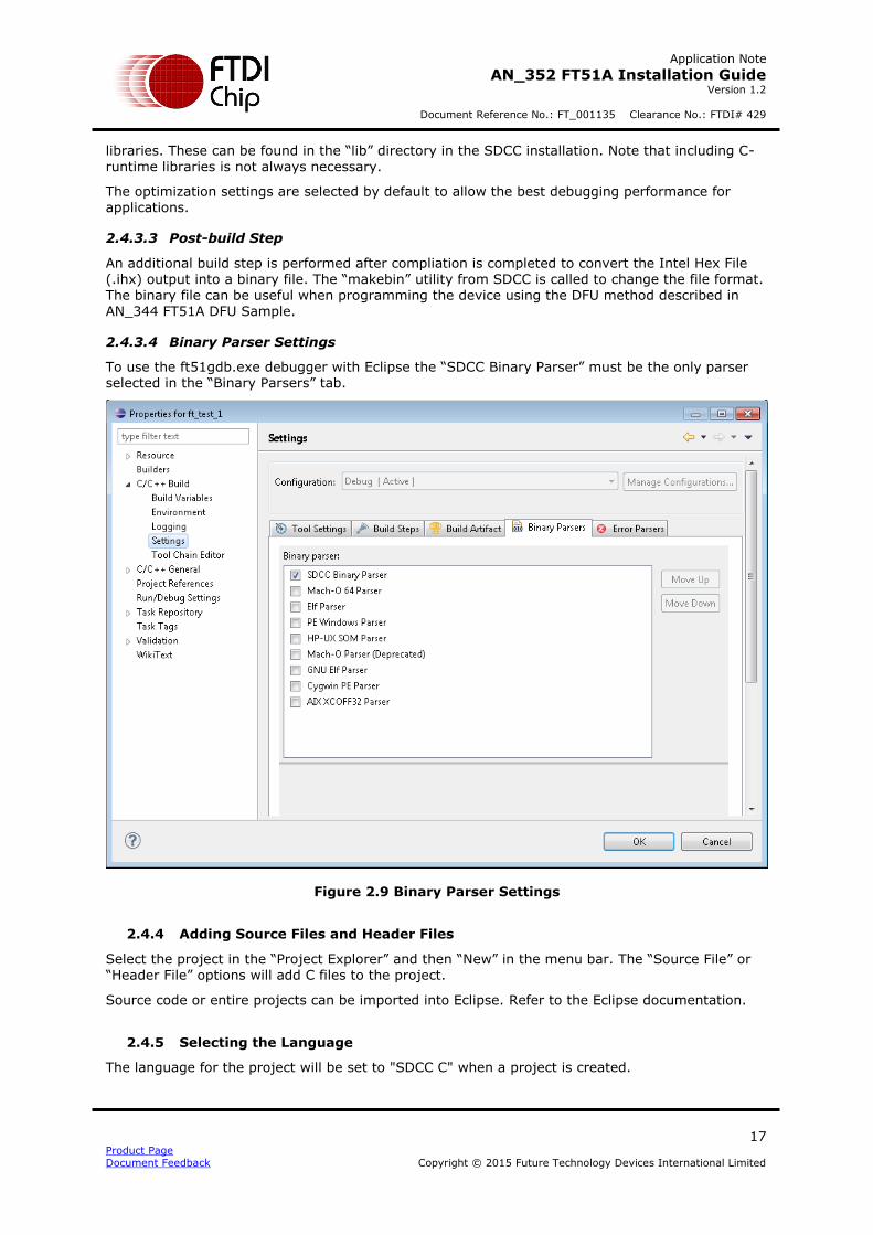
2.4.3.4 Binary Parser Settings
To use the ft51gdb.exe debugger with Eclipse the “SDCC Binary Parser” must be the only parser selected in the “Binary Parsers” tab.
Figure 2.9 Binary Parser Settings
2.4.4 Adding Source Files and Header Files
Select the project in the “Project Explorer” and then “New” in the menu bar. The “Source File” or “Header File” options will add C files to the project.
Source code or entire projects can be imported into Eclipse. Refer to the Eclipse documentation.
2.4.5 Selecting the Language
The language for the project will be set to "SDCC C" when a project is created.

Application Note
AN_352 FT51A Installation Guide Version 1.2
Document Reference No.: FT_001135 Clearance No.: FTDI# 429
18 Product Page Document Feedback Copyright © 2015 Future Technology Devices International Limited
If a file is being added to a project or a project is being converted to use SDCC then the language may need changed. Go to “Project” then “Properties”, select “C/C++ General” then “Language Mappings” and click “Add...”.
In the dialog in Figure 2.10, select “Configuration (All)”, and change language of both “C Header” and “C Source”, to "SDCC C".
Figure 2.10 New Language Mapping
2.4.6 Compiling a Project
The build configuration to compile is chosen by selecting the project in the “Project Explorer”, then “Project” from the menu bar, followed by “Build Configurations” and “Set Active”.
To build the project, again select it in the “Project Explorer” then “Project” from the menu bar and then “Build Project”.
The output of the build process will appear in the “Console” view within Eclipse. This will normally be displayed automatically by Eclipse but can be shown by selecting “Windows” in the menu bar, followed by “Views” then “Console”.
2.5 Adding an Eclipse Debug Configuration
To debug an application within Eclipse it is necessary to make a suitable “Debug Configuration”. This can be done by first selecting the Project to debug then “Run” from the menu bar, and then “Debug Configurations…”.
Before starting to make a debug configuration, it is necessary to compile the project.
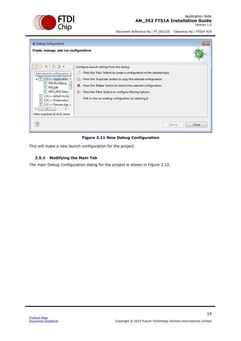
In the Debug Configurations dialog, select “C/C++ Application” and then the “New” button.
Application Note
AN_352 FT51A Installation Guide Version 1.2
Document Reference No.: FT_001135 Clearance No.: FTDI# 429
19 Product Page Document Feedback Copyright © 2015 Future Technology Devices International Limited
Figure 2.11 New Debug Configuration
This will make a new launch configuration for the project.
2.5.1 Modifying the Main Tab
The main Debug Configuration dialog for the project is shown in Figure 2.12.

Application Note
AN_352 FT51A Installation Guide Version 1.2
Document Reference No.: FT_001135 Clearance No.: FTDI# 429
20 Product Page Document Feedback Copyright © 2015 Future Technology Devices International Limited
Figure 2.12 Edit Debug Configuration - Main
In “C/C++ Application:” Click on the “Search Project…” button.

Application Note
AN_352 FT51A Installation Guide Version 1.2
Document Reference No.: FT_001135 Clearance No.: FTDI# 429
21 Product Page Document Feedback Copyright © 2015 Future Technology Devices International Limited
Figure 2.13 Edit Debug Configuration – Search Project
If the file does not exist then it can be typed in manually in the form “Debug/filename.cdb”. There will be a warning and the “Debug” button will be inactive if this is not filled in correctly or the file
does not exist.
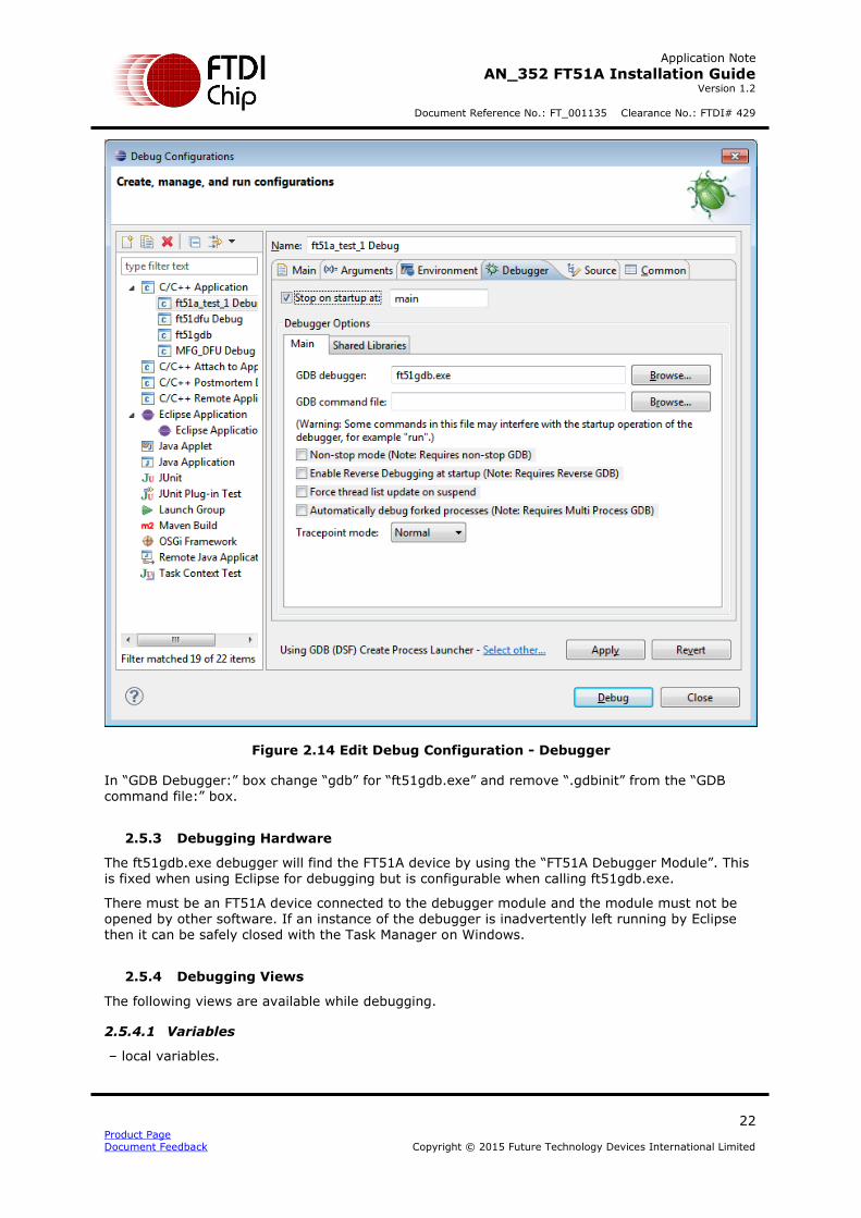
2.5.2 Modifying the Debugger Tab
The “Debugger” tab of the Debug configurations needs modified to select the ft51gdb.exe debugger for the project. See Figure 2.14.
Application Note
AN_352 FT51A Installation Guide Version 1.2
Document Reference No.: FT_001135 Clearance No.: FTDI# 429
22 Product Page Document Feedback Copyright © 2015 Future Technology Devices International Limited
Figure 2.14 Edit Debug Configuration - Debugger
In “GDB Debugger:” box change “gdb” for “ft51gdb.exe” and remove “.gdbinit” from the “GDB command file:” box.
2.5.3 Debugging Hardware
The ft51gdb.exe debugger will find the FT51A device by using the “FT51A Debugger Module”. This is fixed when using Eclipse for debugging but is configurable when calling ft51gdb.exe.
There must be an FT51A device connected to the debugger module and the module must not be opened by other software. If an instance of the debugger is inadvertently left running by Eclipse then it can be safely closed with the Task Manager on Windows.
2.5.4 Debugging Views
The following views are available while debugging.
2.5.4.1 Variables
– local variables.

Application Note
AN_352 FT51A Installation Guide Version 1.2
Document Reference No.: FT_001135 Clearance No.: FTDI# 429
23 Product Page Document Feedback Copyright © 2015 Future Technology Devices International Limited
2.5.4.2 Registers
– all registers including SFRs.
2.5.4.3 Expressions
– Limited evaluation of expressions
Prefix register name by $ to view a register in the “Expressions” view.
“&” for address of
“*” For dereference
“[]” for array offsets
“.” To access structure members
2.5.4.4 Memory
There are 3 memory areas available on the FT51A for displaying in Eclipse: Internal memory, 128 bytes; data memory, 8kB; and program memory, 16kB.
To allow Eclipse to display each of these a sparse memory map is used. An expression for addressing each type of memory will translate into a sparse memory address. Either can be used
to specify a memory address to Eclipse.
Memory Area Expression Sparse Memory Range
Internal int: 0x000000 – 0x000080
Data ext: 0x400000 - 0x402000
Shadow RAM prog: 0x800000 – 0x804000
Table 2.5 Sparse Memory Mappings
The expression prefixes the address required. For example, “ext:0x1000” is offset 4096 in data
memory and “prog:10” is offset 10 in program memory. Figure 2.15 shows internal memory address zero being specified.
Figure 2.15 Memory Address
Note that the memory browser will show the sparse memory address rather than the expression. This can be seen in the “Address” column in Figure 2.16.

Application Note
AN_352 FT51A Installation Guide Version 1.2
Document Reference No.: FT_001135 Clearance No.: FTDI# 429
24 Product Page Document Feedback Copyright © 2015 Future Technology Devices International Limited
Figure 2.16 Memory Rendering
2.5.5 Debugging Restrictions
Maximum of 3 hardware debug locations. Note that when using more than 3 can cause unwanted behaviour within Eclipse.
Due to the way the stack is used, there is no “Step Out” function nor is there a call stack trace
available.
Debugging will step into interrupt routines if one is triggered.
All programs are run from the Shadow RAM. They cannot be programmed into the MTP using the debugger.
2.5.6 Debugging SDCC Compiled Applications
Due to the nature of the small devices which SDCC targets there are inevitably consequences for
debugging.
SDCC is very aggressive in caching variables in registers and some variables may never be stored in internal or data memory. It is very efficient at optimizing variables out and some variables with limited scope may disappear before the end of their stated scope.
Memory locations are limited so the memory locations of variables may be reused.
2.6 Adding an Eclipse Run Configuration
To run (without debugging) an application within Eclipse it is necessary to make a suitable “Run
Configuration”. This can be done in a similar way to a debug configuration by first selecting the Project to debug then “Run” from the menu bar, but then selecting “Run Configurations…”.
It is necessary to compile the project before making a run configuration.
In the Run Configurations dialog, select “C/C++ Application” and then the “New” button.

Application Note
AN_352 FT51A Installation Guide Version 1.2
Document Reference No.: FT_001135 Clearance No.: FTDI# 429
25 Product Page Document Feedback Copyright © 2015 Future Technology Devices International Limited
Figure 2.17 New Run Configuration
The “C/C++ Application” to run is a programming tool called “ft51prg.exe”. This will download the application code to the FT51A without using the debugger. The full path is required to the installation location of the tool. In this example the FT51A Toolchain installer has placed this file in the SDCC bin folder.
The application to run on the target FT51A is added in the “Arguments” tab using variables to
locate the IHX file of the project.
-g -s ${project_loc}\${config_name:${project_name}}\${project_name}.ihx
Application Note
AN_352 FT51A Installation Guide Version 1.2
Document Reference No.: FT_001135 Clearance No.: FTDI# 429
26 Product Page Document Feedback Copyright © 2015 Future Technology Devices International Limited
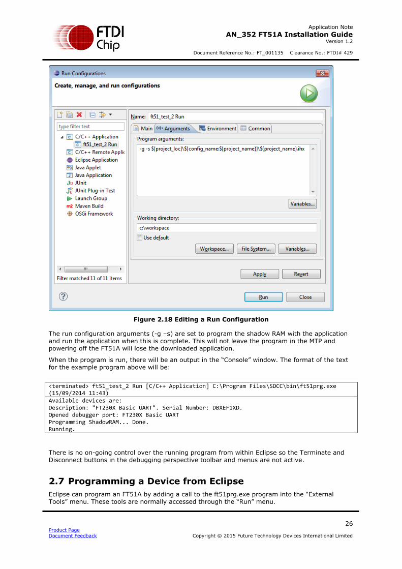
Figure 2.18 Editing a Run Configuration
The run configuration arguments (-g –s) are set to program the shadow RAM with the application and run the application when this is complete. This will not leave the program in the MTP and powering off the FT51A will lose the downloaded application.
When the program is run, there will be an output in the “Console” window. The format of the text for the example program above will be:
<terminated> ft51_test_2 Run [C/C++ Application] C:\Program Files\SDCC\bin\ft51prg.exe (15/09/2014 11:43) Available devices are: Description: "FT230X Basic UART". Serial Number: DBXEF1XD. Opened debugger port: FT230X Basic UART Programming ShadowRAM... Done. Running.
There is no on-going control over the running program from within Eclipse so the Terminate and Disconnect buttons in the debugging perspective toolbar and menus are not active.
2.7 Programming a Device from Eclipse
Eclipse can program an FT51A by adding a call to the ft51prg.exe program into the “External Tools” menu. These tools are normally accessed through the “Run” menu.

Application Note
AN_352 FT51A Installation Guide Version 1.2
Document Reference No.: FT_001135 Clearance No.: FTDI# 429
27 Product Page Document Feedback Copyright © 2015 Future Technology Devices International Limited
The program requires that a debugger board is connected to the FT51A one-wire debug interface.
The parameters for the tool are as described in Section 2.2.2:
A typical command line invocation to run an app called “temp_app” will look like this:
C:\workspace\temp_app\Debug> ft51prg.exe -g temp_app.ihx
Available devices are:
Description: "VII Debugger Module". Serial Number: FTVLN1VR.
Description: "FT230X Basic UART". Serial Number: DBXHBA8K.
Opened debugger port: FT230X Basic UART
Programming ShadowRAM... Done.
Running.
The image to run is the IHX file produced by the SDCC tools.
The tool can be used as an external tool in Eclipse to program and run an application.
The External Tools Configuration is required to run the currently selected program using the ft51prg.exe tool is shown in Figure 2.19.
Figure 2.19 External Tool Configuration for ft51prg.exe

Application Note
AN_352 FT51A Installation Guide Version 1.2
Document Reference No.: FT_001135 Clearance No.: FTDI# 429
28 Product Page Document Feedback Copyright © 2015 Future Technology Devices International Limited
3 SDK File Structure
The FT51A Toolchain installs tool and utility files in the directories underneath the “toolchain” directory as described in Table 3.2. Documentation, examples and source code is installed in the “materials” directory as described in Table 3.1.
Directory Description
Documents Copies of Application Notes Pertaining to the FT51A. AN_289, AN_352, AN_344, AN_345, AN_346, AN_347, AN_348 and AN_349.
Examples Sample code for Application Notes AN_344, AN_345,
AN_346, AN_347, AN_348 and AN_349.
Source Source code and documentation for FT51A libraries.
Table 3.1 FT51A Materials Directories
Directory Description
Toolchain\tools Contains SDCC installation. Copies of FTDI tools ft51gdb.exe, ft51prg.exe and ft51str.exe are patched into the “bin” directory with SDCC.exe.
Toolchain\eclipse Folder for Eclipse.
Toolchain\Update Site P2 repository for Eclipse plugins.
Toolchain\src Source code for FTDI tools ft51gdb.exe, ft51prg.exe and ft51str.exe.
External\GnuWin32 GNU “coreutils” and “make” installation directory.
External\Java8 Java 8 JRE installer.
Table 3.2 FT51A Toolchain Directories
3.1 Uninstallation
The installation process will optionally install copies of the FTDI FT51A Tools to the installation directory of SDCC. It will remove these when uninstalled.
No source code is removed when the FT51A Toolchain is uninstalled. This is to ensure that no user-made changes to source codes are deleted. Once uninstalled it is possible to delete the "FT51A Toolchain Folder" manually to remove these files.
Application Note
AN_352 FT51A Installation Guide Version 1.2
Document Reference No.: FT_001135 Clearance No.: FTDI# 429
29 Product Page Document Feedback Copyright © 2015 Future Technology Devices International Limited
4 Contact Information
Head Office – Glasgow, UK Future Technology Devices International Limited Unit 1, 2 Seaward Place, Centurion Business Park Glasgow G41 1HH United Kingdom Tel: +44 (0) 141 429 2777 Fax: +44 (0) 141 429 2758 E-mail (Sales) [email protected] E-mail (Support) [email protected] E-mail (General Enquiries) [email protected]
Branch Office – Taipei, Taiwan Future Technology Devices International Limited (Taiwan) 2F, No. 516, Sec. 1, NeiHu Road
Taipei 114 Taiwan , R.O.C. Tel: +886 (0) 2 8791 3570 Fax: +886 (0) 2 8791 3576 E-mail (Sales) [email protected] E-mail (Support) [email protected] E-mail (General Enquiries) [email protected]
Branch Office – Tigard, Oregon, USA Future Technology Devices International Limited (USA) 7130 SW Fir Loop Tigard, OR 97223-8160 USA Tel: +1 (503) 547 0988 Fax: +1 (503) 547 0987 E-Mail (Sales) [email protected] E-Mail (Support) [email protected] E-Mail (General Enquiries) [email protected]
Branch Office – Shanghai, China Future Technology Devices International Limited (China) Room 1103, No. 666 West Huaihai Road,
Shanghai, 200052 China Tel: +86 21 62351596 Fax: +86 21 62351595 E-mail (Sales) [email protected] E-mail (Support) [email protected] E-mail (General Enquiries) [email protected]
Web Site http://ftdichip.com
System and equipment manufacturers and designers are
responsible to ensure that their systems, and any Future
Technology Devices International Ltd (FTDI) devices
incorporated in their systems, meet all applicable safety, regulatory and system-level performance requirements.
All application-related information in this document
(including application descriptions, suggested FTDI
devices and other materials) is provided for reference
only. While FTDI has taken care to assure it is accurate,
this information is subject to customer confirmation, and
FTDI disclaims all liability for system designs and for any
applications assistance provided by FTDI. Use of FTDI
devices in life support and/or safety applications is
entirely at the user’s risk, and the user agrees to defend,
indemnify and hold harmless FTDI from any and all damages, claims, suits or expense resulting from such
use. This document is subject to change without notice.
No freedom to use patents or other intellectual property
rights is implied by the publication of this document.
Neither the whole nor any part of the information
contained in, or the product described in this document,
may be adapted or reproduced in any material or
electronic form without the prior written consent of the
copyright holder. Future Technology Devices International Ltd, Unit 1, 2 Seaward Place, Centurion Business Park,
Glasgow G41 1HH, United Kingdom. Scotland Registered
Company Number: SC136640

Application Note
AN_352 FT51A Installation Guide Version 1.2
Document Reference No.: FT_001135 Clearance No.: FTDI# 429
30 Product Page Document Feedback Copyright © 2015 Future Technology Devices International Limited
Appendix A – References
Document References
FTDI MCU web page: http://www.ftdichip.com/MCU.html
AN_344_FT51A_DFU_Sample
AN_345_FT51A_Keyboard_Sample AN_346_FT51A_Mouse_Sample AN_347_FT51A_Test_and_Measurement_Sample AN_348_FT51A_FT800_Sensors_Sample AN_349_FT51A_FT800_Spaced_Invaders_Sample
SDCC web page: http://sdcc.sourceforge.net
Eclipse CDT web page: http://www.eclipse.org/cdt
GnuWin32 make web page: http://gnuwin32.sourceforge.net/packages/make.htm
GnuWin32 coreutils web page: http://gnuwin32.sourceforge.net/packages/coreutils.htm
Eclipse SDCC web page: http://eclipse-sdcc.sourceforge.net
Hex2Bin web page: http://hex2bin.sourceforge.net
MinGW web page: http://www.mingw.org
GDB online documentation web page: https://sourceware.org/gdb/onlinedocs/gdb
USB Test and Measurement Class specification: http://www.usb.org/developers/docs/devclass_docs/USBTMC_1_006a.zip
USB Device Firmware Update Class specification: http://www.usb.org/developers/docs/devclass_docs/DFU_1.1.pdf
Acronyms and Abbreviations
Terms Description
USB Universal Serial Bus
USB-IF USB Implementers Forum
MTP Multiple Time Program – non-volatile memory used to store program code
on the FT51A.
SDCC Small Device C Compiler
GPL Gnu Public License
EPL Eclipse Public License

Application Note
AN_352 FT51A Installation Guide Version 1.2
Document Reference No.: FT_001135 Clearance No.: FTDI# 429
31 Product Page Document Feedback Copyright © 2015 Future Technology Devices International Limited
Appendix B – List of Tables & Figures
List of Tables
Table 2.1 Development Tools................................................................................................ 6
Table 2.2 Additional Tools ................................................................................................... 6
Table 2.3 FTDIChip Plugin for FT51A...................................................................................... 9
Table 2.4 MI Commands Implemented in ft51gdb.exe ........................................................... 10
Table 2.5 Sparse Memory Mappings .................................................................................... 23
Table 3.1 FT51A Materials Directories .................................................................................. 28
Table 3.2 FT51A Toolchain Directories ................................................................................. 28
List of Figures
Figure 2.1 Installing CDT ..................................................................................................... 7
Figure 2.2 Installing FTDI Plugin ........................................................................................... 8
Figure 2.3 New Project Dialog ............................................................................................. 12
Figure 2.4 C Project Dialog ................................................................................................. 13
Figure 2.5 Basic Project for SDCC Workspace ....................................................................... 14
Figure 2.6 Basic Project for SDCC Workspace ....................................................................... 14
Figure 2.7 C Project Properties ........................................................................................... 16
Figure 2.8 Tool Settings ..................................................................................................... 16
Figure 2.9 Binary Parser Settings ........................................................................................ 17
Figure 2.10 New Language Mapping .................................................................................... 18
Figure 2.11 New Debug Configuration .................................................................................. 19
Figure 2.12 Edit Debug Configuration - Main......................................................................... 20
Figure 2.13 Edit Debug Configuration – Search Project .......................................................... 21
Figure 2.14 Edit Debug Configuration - Debugger ................................................................. 22
Figure 2.15 Memory Address .............................................................................................. 23
Figure 2.16 Memory Rendering ........................................................................................... 24
Figure 2.17 New Run Configuration ..................................................................................... 25
Figure 2.18 Editing a Run Configuration ............................................................................... 26
Figure 2.19 External Tool Configuration for ft51prg.exe ......................................................... 27

Application Note
AN_352 FT51A Installation Guide Version 1.2
Document Reference No.: FT_001135 Clearance No.: FTDI# 429
32 Product Page Document Feedback Copyright © 2015 Future Technology Devices International Limited
Appendix C – Revision History
Document Title: AN_352 FT51A Installation Guide
Document Reference No.: FT_001135
Clearance No.: FTDI# 429
Product Page: http://www.ftdichip.com/FTProducts.htm
Document Feedback: Send Feedback
Revision Changes Date
1.0 Initial Release 2014-12-12
1.1 Update FT51 references to FT51A 2015-11-26
1.2 Updated DFU and Installer name 2015-12-21