ft-817nd_operating manual
TRANSCRIPT
HF/VHF/UHF
ALL MODE TRANSCEIVER
FT-817ND
OPERATING MANUAL
VERTEX STANDARD CO., LTD.4-8-8 Nakameguro, Meguro-Ku, Tokyo 153-8644, Japan
VERTEX STANDARDUS Headquarters10900 Walker Street, Cypress, CA 90630, U.S.A.
YAESU EUROPE B.V.P.O. Box 75525, 1118 ZN Schiphol, The Netherlands
YAESU UK LTD.Unit 12, Sun Valley Business Park, Winnall CloseWinchester, Hampshire, SO23 0LB, U.K.
VERTEX STANDARD HK LTD.Unit 5, 20/F., Seaview Centre, 139-141 Hoi Bun Road,Kwun Tong, Kowloon, Hong Kong
Introduction .................................................... 1
Specifications .................................................. 2
Accessories & Options ................................... 4
Plug Pinout ...................................................... 5
Installation ...................................................... 6
Connecting the Supplied YHA-63 Antenna ......... 6
Connecting the Microphone ................................. 7
Shoulder Strap Installation ................................... 7
Rubber Foot Installation ....................................... 7
Alkaline Battery Installation and Use .................. 8
External Power Connections ................................ 9
FNB-85 Ni-Cd Battery Pack Installation and Use .. 10
Front Panel Control & Switches ................. 12
Side Panel Switch & Connectors ................ 16
Rear Panel Connectors ................................ 17
Operation ...................................................... 18
Turning the Transceiver On and Off .................. 18
Supply Voltage Display ...................................... 18
Operating Band Selection .................................. 19
Mode Selection ................................................... 19
Adjusting the Audio Volume Level .................... 19
Menu Quick Start ............................................... 20
Adjusting the RF Gain and Squelch ................... 20
Setting the Operating Frequency ........................ 21
Stacked VFO System ......................................... 21
Operation on 5 MHz Band
(U.S. Version Only) ............................................ 22
Receiver Accessories ..................................... 23
Clarifier (Receiver incremental Tuning) ............ 23
IF SHIFT ............................................................ 24
AGC (Automatic Gain Control) ......................... 25
Noise Blanker ..................................................... 25
IPO (Intercept Point Optimization) .................... 25
ATT (Front End Attenuator) ............................... 26
AM/FM DIAL .................................................... 26
Automatic Power-Off Feature ............................ 27
Transmitter Operation ................................. 28
SSB Transmission .............................................. 28
Basic Setup/Operation ................................... 28
Adjusting the transmitter Power Output ... 28
VOX Operation ............................................. 29
CW Transmission ............................................... 30
Operation using Straight Key/
External Keying Device ................................ 30
Operation using
the Built-in Electronic Keyer ........................ 32
FM Transmission ................................................ 33
Basic Setup/Operation ................................... 33
Repeater Operation ........................................ 33
Tone Search Scanning ............................... 35
DCS Operation .............................................. 36
DCS Search Scanning ............................... 36
ARTSTM (Auto Range Transpond System)
Operation ....................................................... 37
CW Identifier Setup ....................................... 37
Digital Mode Operation (SSB-Based AFSK) .... 38
RTTY (Radio TeleType) Operation ............... 38
PSK31 Operation ........................................... 39
“USER” Defined Digital Modes ................... 40
Packet (1200/9600 bps FM) Operation .............. 41
AM Transmission ............................................... 42
Split Frequency Operation ................................. 42
Time-Out Timer .................................................. 43
WeatherFax Monitoring ..................................... 43
Memory Operation ...................................... 44
QMB Channel ..................................................... 44
Memory Operation on
“Regular” Memory Channels ............................. 45
Normal Memory Storage .............................. 45
Split-Frequency Memory Storage ................. 45
Memory Channel Recall ................................ 46
Masking Memory .......................................... 47
Memory Operation on
“HOME” Channel Memories ............................. 48
Labeling Memories ............................................ 49
Spectrum Scope Monitor Operation .......... 50
Smart SearchTM Operation .......................... 51
Scanning Operation ..................................... 52
Scanning Operation ............................................ 52
Scan Skip Programming (Memory Mode Only) .... 52
Scan-Resume Choices .............................. 52
Programmable Memory Scan (PMS) Operation . 54
Dual Watch Operation ................................. 56
Operation on Alaska Emergency Frequency:
5167.5 kHz (U.S. Version Only) ........................ 57
Menu Operation ........................................... 58
Clonning ........................................................ 69
CAT System Programming ....................... 70
Installation of Optional Accessories ........... 74
Option Filters YF-122S/YF-122C ................... 74
High-Stability Reference Oscillator TCXO-9 ... 75
Power-on Microprocessor Reset Procedure ..... 76
Appendix ....................................................... 77
Setup of Memories for Low Earth Orbit (LEO)
FM Satellite Operation ....................................... 77
BAND DATA Format ......................................... 80
Contents
1FT-817ND Operating Manual
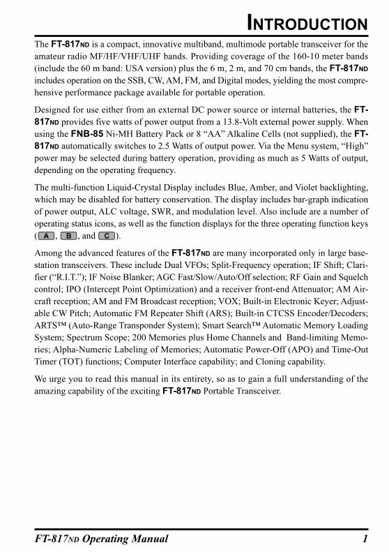
The FT-817ND is a compact, innovative multiband, multimode portable transceiver for the
amateur radio MF/HF/VHF/UHF bands. Providing coverage of the 160-10 meter bands
(include the 60 m band: USA version) plus the 6 m, 2 m, and 70 cm bands, the FT-817ND
includes operation on the SSB, CW, AM, FM, and Digital modes, yielding the most compre-
hensive performance package available for portable operation.
Designed for use either from an external DC power source or internal batteries, the FT-
817ND provides five watts of power output from a 13.8-Volt external power supply. When
using the FNB-85 Ni-MH Battery Pack or 8 “AA” Alkaline Cells (not supplied), the FT-
817ND automatically switches to 2.5 Watts of output power. Via the Menu system, “High”
power may be selected during battery operation, providing as much as 5 Watts of output,
depending on the operating frequency.
The multi-function Liquid-Crystal Display includes Blue, Amber, and Violet backlighting,
which may be disabled for battery conservation. The display includes bar-graph indication
of power output, ALC voltage, SWR, and modulation level. Also include are a number of
operating status icons, as well as the function displays for the three operating function keys
( , , and ).
Among the advanced features of the FT-817ND are many incorporated only in large base-
station transceivers. These include Dual VFOs; Split-Frequency operation; IF Shift; Clari-
fier (“R.I.T.”); IF Noise Blanker; AGC Fast/Slow/Auto/Off selection; RF Gain and Squelch
control; IPO (Intercept Point Optimization) and a receiver front-end Attenuator; AM Air-
craft reception; AM and FM Broadcast reception; VOX; Built-in Electronic Keyer; Adjust-
able CW Pitch; Automatic FM Repeater Shift (ARS); Built-in CTCSS Encoder/Decoders;
ARTS™ (Auto-Range Transponder System); Smart Search™ Automatic Memory Loading
System; Spectrum Scope; 200 Memories plus Home Channels and Band-limiting Memo-
ries; Alpha-Numeric Labeling of Memories; Automatic Power-Off (APO) and Time-Out
Timer (TOT) functions; Computer Interface capability; and Cloning capability.
We urge you to read this manual in its entirety, so as to gain a full understanding of the
amazing capability of the exciting FT-817ND Portable Transceiver.
INTRODUCTION
2 FT-817ND Operating Manual
GENERAL
Frequency Range: Receive: 100 kHz-30 MHz
50 MHz-54 MHz
76 MHz-108 MHz (WFM only)
87.5 MHz-108 MHz (EU)
108 MHz-154 MHz (USA)
144 MHz-148 (146) MHz (Other markets)
430 (420) MHz-450 (440) MHz
Transmit: 160-6 Meters (USA: includes 60 meters)
2 Meters
70 Centimeters (Amateur bands only)
5.1675 MHz Alaska Emergency Frequency (USA only)
Emission Modes: A1 (CW), A3 (AM), A3J (LSB/USB), F3 (FM),
F1 (9600 bps packet), F2 (1200 bps packet)
Synthesizer Steps (Min.): 10 Hz (CW/SSB), 100 Hz (AM/FM)
Antenna Impedance: 50 Ohms, Unbalanced (Front: Type BNC, Rear: Type M)
Operating Temp. Range: –10 °C to +60 °C (+14 °F to +140 °F)
Frequency Stability: ±4 ppm from 1 min. to 60 min after power on.
@25 °C: 1 ppm/hour
±0.5 ppm/1 hour @25 °C, after warmup (with optional TCXO-9)
Supply Voltage: Normal: 13.8 VDC ± 15 %, Negative Ground
Operating: 8.0-16.0 V, Negative Ground
FBA-28 (w/8 “AA” Alkaline Cells): 12.0 V
FNB-85 (Ni-MH Battery Pack): 9.6 V
Current Consumption: Squelched: 250 mA (Approx.)
Receive: 450 mA
Transmit: 2.0 A
Case Size (W x H x D): 135 x 38 x 165 mm (5.31” x 1.5” x 6.50”)
Weight (Approx.): 1.17 kg (2.58 lb) w/Alkaline battery, antenna, w/o Microphone
TRANSMITTER
RF Power Output: 5 W (SSB/CW/FM), 1.5 W (AM Carrier) @13.8 V
Modulation Types: SSB: Balanced Modulator
AM: Early Stage (Low Level)
FM: Variable Reactance
FM Maximum Deviation: ±5 kHz (FM-N: ±2.5 kHz)
Spurious Radiation: –50 dB (1.8-29.7 MHz)
–60 dB (50/144/430 MHz)
Carrier Suppression: >40 dB
Opp. Sideband Supp.: >50 dB
SSB Frequency Response: 400 Hz-2600 Hz (–6 dB)
Microphone Impedance: 200-10k Ohms (Nominal: 600 Ohms)
SPECIFICATIONS
3FT-817ND Operating Manual
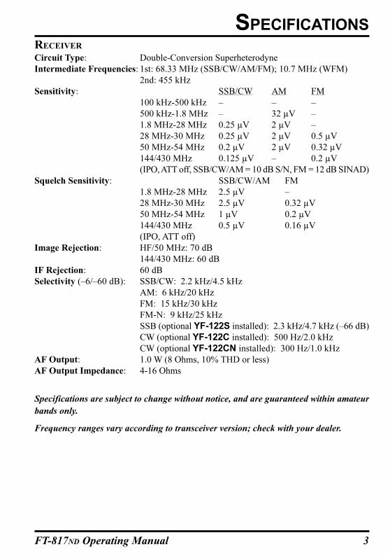
RECEIVER
Circuit Type: Double-Conversion Superheterodyne
Intermediate Frequencies: 1st: 68.33 MHz (SSB/CW/AM/FM); 10.7 MHz (WFM)
2nd: 455 kHz
Sensitivity: SSB/CW AM FM
100 kHz-500 kHz – – –
500 kHz-1.8 MHz – 32 µV –
1.8 MHz-28 MHz 0.25 µV 2 µV –
28 MHz-30 MHz 0.25 µV 2 µV 0.5 µV
50 MHz-54 MHz 0.2 µV 2 µV 0.32 µV
144/430 MHz 0.125 µV – 0.2 µV
(IPO, ATT off, SSB/CW/AM = 10 dB S/N, FM = 12 dB SINAD)
Squelch Sensitivity: SSB/CW/AM FM
1.8 MHz-28 MHz 2.5 µV –
28 MHz-30 MHz 2.5 µV 0.32 µV
50 MHz-54 MHz 1 µV 0.2 µV
144/430 MHz 0.5 µV 0.16 µV
(IPO, ATT off)
Image Rejection: HF/50 MHz: 70 dB
144/430 MHz: 60 dB
IF Rejection: 60 dB
Selectivity (–6/–60 dB): SSB/CW: 2.2 kHz/4.5 kHz
AM: 6 kHz/20 kHz
FM: 15 kHz/30 kHz
FM-N: 9 kHz/25 kHz
SSB (optional YF-122S installed): 2.3 kHz/4.7 kHz (–66 dB)
CW (optional YF-122C installed): 500 Hz/2.0 kHz
CW (optional YF-122CN installed): 300 Hz/1.0 kHz
AF Output: 1.0 W (8 Ohms, 10% THD or less)
AF Output Impedance: 4-16 Ohms
Specifications are subject to change without notice, and are guaranteed within amateur
bands only.
Frequency ranges vary according to transceiver version; check with your dealer.
SPECIFICATIONS
4 FT-817ND Operating Manual
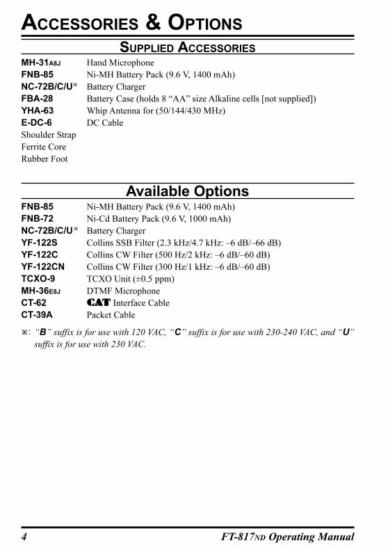
SUPPLIED ACCESSORIES
MH-31A8J Hand Microphone
FNB-85 Ni-MH Battery Pack (9.6 V, 1400 mAh)
NC-72B/C/U Battery Charger
FBA-28 Battery Case (holds 8 “AA” size Alkaline cells [not supplied])
YHA-63 Whip Antenna for (50/144/430 MHz)
E-DC-6 DC Cable
Shoulder Strap
Ferrite Core
Rubber Foot
Available OptionsFNB-85 Ni-MH Battery Pack (9.6 V, 1400 mAh)
FNB-72 Ni-Cd Battery Pack (9.6 V, 1000 mAh)
NC-72B/C/U Battery Charger
YF-122S Collins SSB Filter (2.3 kHz/4.7 kHz: –6 dB/–66 dB)
YF-122C Collins CW Filter (500 Hz/2 kHz: –6 dB/–60 dB)
YF-122CN Collins CW Filter (300 Hz/1 kHz: –6 dB/–60 dB)
TCXO-9 TCXO Unit (±0.5 ppm)
MH-36E8J DTMF Microphone
CT-62 CAT Interface Cable
CT-39A Packet Cable
: “B” suffix is for use with 120 VAC, “C” suffix is for use with 230-240 VAC, and “U”
suffix is for use with 230 VAC.
ACCESSORIES & OPTIONS
5FT-817ND Operating Manual
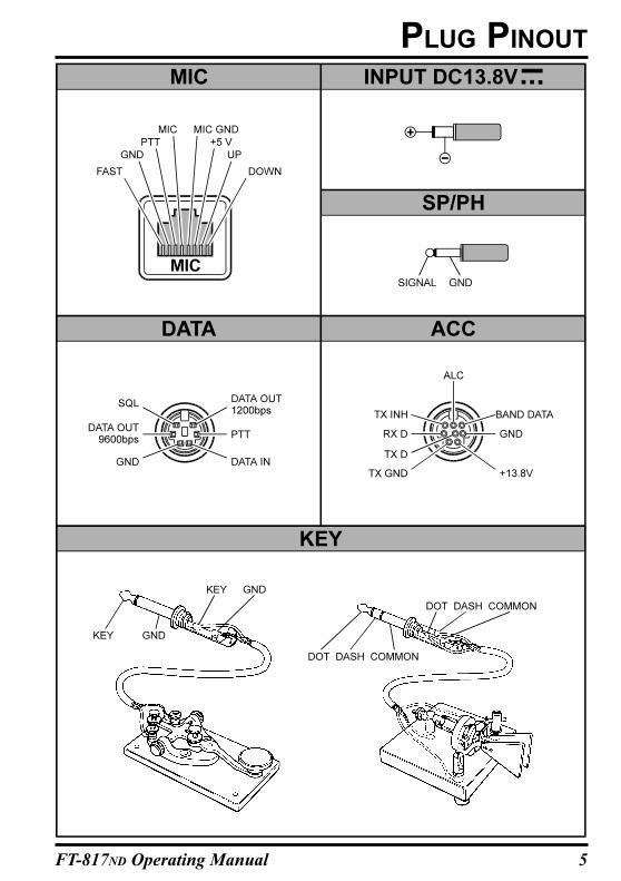
PLUG PINOUT
6 FT-817ND Operating Manual
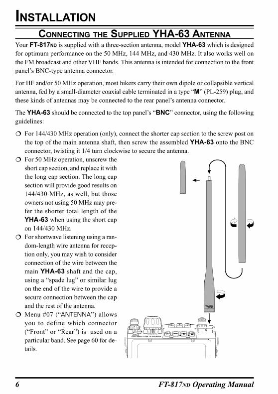
CONNECTING THE SUPPLIED YHA-63 ANTENNA
Your FT-817ND is supplied with a three-section antenna, model YHA-63 which is designed
for optimum performance on the 50 MHz, 144 MHz, and 430 MHz. It also works well on
the FM broadcast and other VHF bands. This antenna is intended for connection to the front
panel’s BNC-type antenna connector.
For HF and/or 50 MHz operation, most hikers carry their own dipole or collapsible vertical
antenna, fed by a small-diameter coaxial cable terminated in a type “M” (PL-259) plug, and
these kinds of antennas may be connected to the rear panel’s antenna connector.
The YHA-63 should be connected to the top panel’s “BNC” connector, using the following
guidelines:
For 144/430 MHz operation (only), connect the shorter cap section to the screw post on
the top of the main antenna shaft, then screw the assembled YHA-63 onto the BNC
connector, twisting it 1/4 turn clockwise to secure the antenna.
For 50 MHz operation, unscrew the
short cap section, and replace it with
the long cap section. The long cap
section will provide good results on
144/430 MHz, as well, but those
owners not using 50 MHz may pre-
fer the shorter total length of the
YHA-63 when using the short cap
on 144/430 MHz.
For shortwave listening using a ran-
dom-length wire antenna for recep-
tion only, you may wish to consider
connection of the wire between the
main YHA-63 shaft and the cap,
using a “spade lug” or similar lug
on the end of the wire to provide a
secure connection between the cap
and the rest of the antenna.
Menu #07 (“ANTENNA”) allows
you to define which connector
(“Front” or “Rear”) is used on a
particular band. See page 60 for de-
tails.
INSTALLATION
7FT-817ND Operating Manual
INSTALLATION
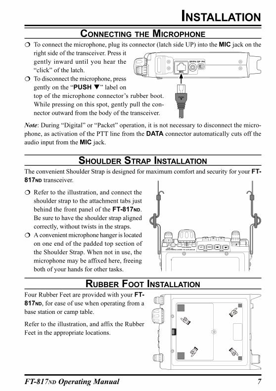
CONNECTING THE MICROPHONE
To connect the microphone, plug its connector (latch side UP) into the MIC jack on the
right side of the transceiver. Press it
gently inward until you hear the
“click” of the latch.
To disconnect the microphone, press
gently on the “PUSH ” label on
top of the microphone connector’s rubber boot.
While pressing on this spot, gently pull the con-
nector outward from the body of the transceiver.
Note: During “Digital” or “Packet” operation, it is not necessary to disconnect the micro-
phone, as activation of the PTT line from the DATA connector automatically cuts off the
audio input from the MIC jack.
SHOULDER STRAP INSTALLATION
The convenient Shoulder Strap is designed for maximum comfort and security for your FT-
817ND transceiver.
Refer to the illustration, and connect the
shoulder strap to the attachment tabs just
behind the front panel of the FT-817ND.
Be sure to have the shoulder strap aligned
correctly, without twists in the straps.
A convenient microphone hanger is located
on one end of the padded top section of
the Shoulder Strap. When not in use, the
microphone may be affixed here, freeing
both of your hands for other tasks.
RUBBER FOOT INSTALLATION
Four Rubber Feet are provided with your FT-
817ND, for ease of use when operating from a
base station or camp table.
Refer to the illustration, and affix the Rubber
Feet in the appropriate locations.
8 FT-817ND Operating Manual
LKALINE BATTERY INSTALLATION AND USE
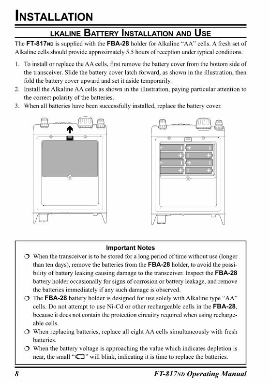
The FT-817ND is supplied with the FBA-28 holder for Alkaline “AA” cells. A fresh set of
Alkaline cells should provide approximately 5.5 hours of reception under typical conditions.
1. To install or replace the AA cells, first remove the battery cover from the bottom side of
the transceiver. Slide the battery cover latch forward, as shown in the illustration, then
fold the battery cover upward and set it aside temporarily.
2. Install the Alkaline AA cells as shown in the illustration, paying particular attention to
the correct polarity of the batteries.
3. When all batteries have been successfully installed, replace the battery cover.
INSTALLATION
Important Notes
When the transceiver is to be stored for a long period of time without use (longer
than ten days), remove the batteries from the FBA-28 holder, to avoid the possi-
bility of battery leaking causing damage to the transceiver. Inspect the FBA-28
battery holder occasionally for signs of corrosion or battery leakage, and remove
the batteries immediately if any such damage is observed.
The FBA-28 battery holder is designed for use solely with Alkaline type “AA”
cells. Do not attempt to use Ni-Cd or other rechargeable cells in the FBA-28,
because it does not contain the protection circuitry required when using recharge-
able cells.
When replacing batteries, replace all eight AA cells simultaneously with fresh
batteries.
When the battery voltage is approaching the value which indicates depletion is
near, the small “ ” will blink, indicating it is time to replace the batteries.
9FT-817ND Operating Manual
INSTALLATION
EXTERNAL POWER CONNECTIONS
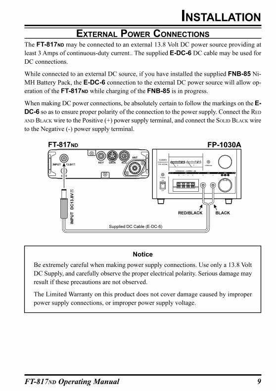
The FT-817ND may be connected to an external 13.8 Volt DC power source providing at
least 3 Amps of continuous-duty current.. The supplied E-DC-6 DC cable may be used for
DC connections.
While connected to an external DC source, if you have installed the supplied FNB-85 Ni-
MH Battery Pack, the E-DC-6 connection to the external DC power source will allow op-
eration of the FT-817ND while charging of the FNB-85 is in progress.
When making DC power connections, be absolutely certain to follow the markings on the E-
DC-6 so as to ensure proper polarity of the connection to the power supply. Connect the RED
AND BLACK wire to the Positive (+) power supply terminal, and connect the SOLID BLACK wire
to the Negative (-) power supply terminal.
Notice
Be extremely careful when making power supply connections. Use only a 13.8 Volt
DC Supply, and carefully observe the proper electrical polarity. Serious damage may
result if these precautions are not observed.
The Limited Warranty on this product does not cover damage caused by improper
power supply connections, or improper power supply voltage.
FT-817ND
10 FT-817ND Operating Manual
FNB-85 NI-MH BATTERY PACK INSTALLATION AND USE
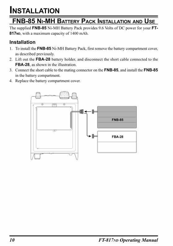
The supplied FNB-85 Ni-MH Battery Pack provides 9.6 Volts of DC power for your FT-
817ND, with a maximum capacity of 1400 mAh.
Installation
1. To install the FNB-85 Ni-MH Battery Pack, first remove the battery compartment cover,
as described previously.
2. Lift out the FBA-28 battery holder, and disconnect the short cable connected to the
FBA-28, as shown in the illustration.
3. Connect the short cable to the mating connector on the FNB-85, and install the FNB-85
in the battery compartment.
4. Replace the battery compartment cover.
INSTALLATION
FNB-85
FBA-28
11FT-817ND Operating Manual
FNB-85 NI-MH BATTERY PACK INSTALLATION AND USE
INSTALLATION
Charging
Charging of the FNB-85 requires the use of either the supplied NC-72B/C* charger, or an
external 13.8 Volt (±15%) DC source. If the NC-72B/C is used, the FT-817ND must be
turned off during charging; if an external 13.8 Volt DC source is used (connected via the
supplied E-DC-6 cable), then you may operate the FT-817ND while charging is in progress.
1. Turn the FT-817ND off (see page 18), then connect the supplied NC-72B/C DC connec-
tor to the INPUT: 13.8V jack on the rear panel of the FT-817ND.
2. Plug the NC-72B/C into the nearest AC wall outlet.
3. Press the FT-817ND’s switch for one second to turn the transceiver on.
4. Press the key momentarily.
5. Rotate the knob so that the function row containing “[CHG, VLT, DSP]” appears
on the display.
6. Press the key to select the [CHG] option (the display will immediately revert to the
regular frequency display).
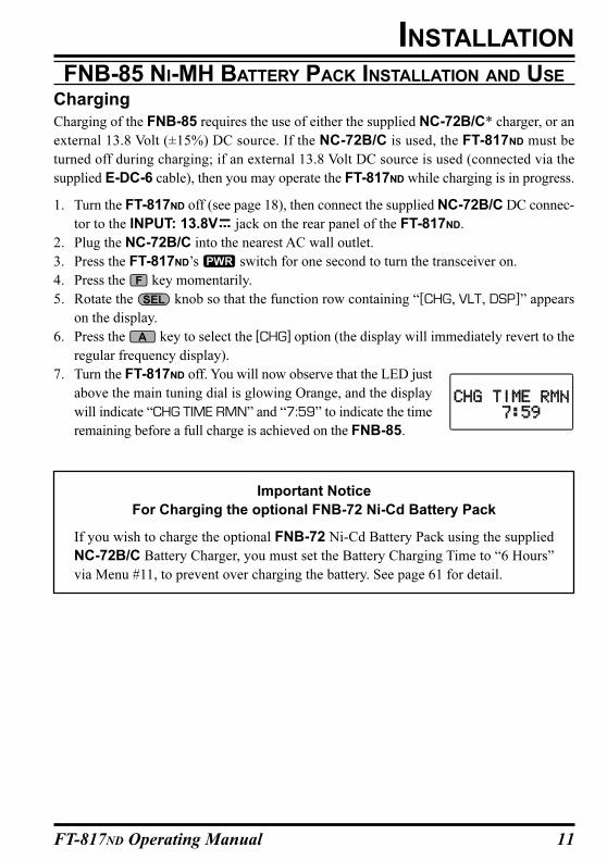
7. Turn the FT-817ND off. You will now observe that the LED just
above the main tuning dial is glowing Orange, and the display
will indicate “CHG TIME RMN” and “7:59” to indicate the time
remaining before a full charge is achieved on the FNB-85.
Important Notice
For Charging the optional FNB-72 Ni-Cd Battery Pack
If you wish to charge the optional FNB-72 Ni-Cd Battery Pack using the supplied
NC-72B/C Battery Charger, you must set the Battery Charging Time to “6 Hours”
via Menu #11, to prevent over charging the battery. See page 61 for detail.
12 FT-817ND Operating Manual
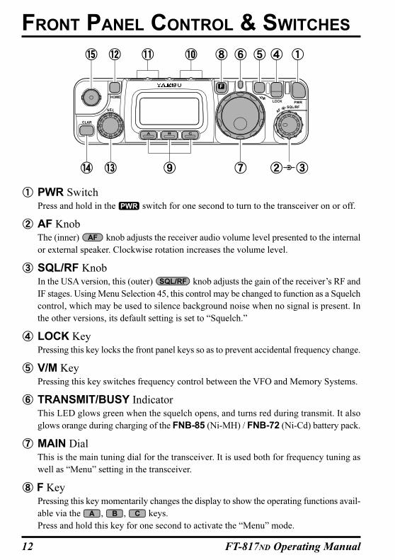
PWR SwitchPress and hold in the switch for one second to turn to the transceiver on or off.
AF KnobThe (inner) knob adjusts the receiver audio volume level presented to the internal
or external speaker. Clockwise rotation increases the volume level.
SQL/RF KnobIn the USA version, this (outer) knob adjusts the gain of the receiver’s RF and
IF stages. Using Menu Selection 45, this control may be changed to function as a Squelch
control, which may be used to silence background noise when no signal is present. In
the other versions, its default setting is set to “Squelch.”
LOCK KeyPressing this key locks the front panel keys so as to prevent accidental frequency change.
V/M KeyPressing this key switches frequency control between the VFO and Memory Systems.
TRANSMIT/BUSY IndicatorThis LED glows green when the squelch opens, and turns red during transmit. It also
glows orange during charging of the FNB-85 (Ni-MH) / FNB-72 (Ni-Cd) battery pack.
MAIN DialThis is the main tuning dial for the transceiver. It is used both for frequency tuning as
well as “Menu” setting in the transceiver.
F KeyPressing this key momentarily changes the display to show the operating functions avail-
able via the , , keys.
Press and hold this key for one second to activate the “Menu” mode.
FRONT PANEL CONTROL & SWITCHES
13FT-817ND Operating Manual
FRONT PANEL CONTROL & SWITCHES
FUNC KeysThese three keys select many of the most important operating features of the trans-
ceiver. When pressing the key, the current function of that key appears above each
of the , , keys (along the bottom of the LCD); rotating the knob
scrolls the display through eleven rows of functions available for use via the , ,
keys.
The available features are shown in chart on the next page.
BAND(DWN)/BAND(UP) KeyPressing either of these keys momentarily will cause the frequency to be moved up or
down by one frequency band. The selections available are:
Recalling the 5 MHz band (U.S. model) requires different procedure. See page 22 for
details.
MODE()/MODE() KeyPressing either of these keys momentarily will change the operating mode. The selec-
tions available are:
HOME KeyPressing this key momentarily recalls a favorite “HOME” frequency memory.
SEL KnobThis detented rotary switch is used for tuning, memory selection, and function selection
for the , , keys of the transceiver.
CLAR KeyPress this key momentarily to activate the Receiver Clarifier feature. When this feature
is activated, the knob may be used to set a tuning offset of up to ±9.99 kHz. The
transmitter’s frequency is not affected by the setting of the Clarifier.
Press and hold this key for 1/2 second to activate the IF Shift feature, which allows you
to use the knob to adjust the center frequency of the IF filter’s passband response.
ANT JackConnect the supplied 50/144/430 MHz rubber flex antenna (or another antenna present-
ing a 50Ω impedance) to this BNC connector.
In its default setting, this jack does not function on the HF bands. If you want to enable
this jack on the HF bands, recall and change the setting of Menu #07.
14 FT-817ND Operating Manual
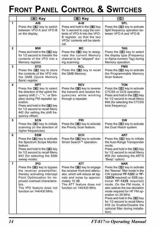
SPLPress the key to activateSplit frequency operation be-tween VFO-A and VFO-B.
TAGPress the key to selectthe display type (Frequencyor Alpha-numeric Tag) duringMemory operation.
PMSPress the key to activatethe Programmable MemoryScan feature.
TONPress the key to activateCTCSS or DCS operation.Press and hold in the keyfor 1/2 second to recall Menu#48 (for selecting the CTCSStone frequency).
DWPress the key to activatethe Dual Watch system.
ARTPress the key to initiatethe Auto-Range Transpondermode.Press and hold in the keyfor 1/2 second to recall Menu#09 (for selecting the ARTS“Beep” option).
NARPress the key to activatethe “Narrow” filter mode in theCW (optional YF-122C or YF-122CN required) or SSB (op-tional YF-122S required)mode. On the FM mode, italso selects the low-deviationmode required for HF FM op-eration on 29 MHz.Press and hold in the keyfor 1/2 second to recall Menu#38 (to Enable/Disable theoptional filter during installa-tion).
A/BPress the key to switchbetween VFO-A and VFO-Bon the display.
MWPress and hold in the keyfor 1/2 second to transfer thecontents of the VFO into aMemory register.
STOPress the key to storethe contents of the VFO intothe QMB (Quick MemoryBank) register.
RPTPress the key to selectthe direction of the uplink fre-quency shift (“–,” “+,” or Sim-plex) during FM repeater op-eration.Press and hold in the keyfor 1/2 second to recall Menu#42 (for setting the shift fre-quency offset).
SCNPress the key to initiatescanning (in the direction ofhigher frequencies).
SSMPress the key to activatethe Spectrum Scope Monitorfeature.Press and hold in the keyfor 1/2 second to recall Menu#43 (for selecting the SSMsweep mode).
IPOPress the key to bypassthe receiver preamplifier,thereby activating InterceptPoint Optimization for im-proved overload characteris-tics.The IPO feature does notfunction on 144/430 MHz.
A=BPress and hold in the keyfor ½ second to copy the con-tents of VFO-A into the VFO-B register, so that the twoVFOs’ contents will be identi-cal.
MCPress the key to desig-nate the current Memorychannel to be “skipped” dur-ing scanning.
RCLPress the key to recallthe QMB Memory.
REVPress the key to reversethe transmit and receive fre-quencies whi le workingthrough a repeater.
PRIPress the key to activatethe Priority Scan feature.
SCHPress the key to activateSmart SearchTM operation.
ATTPress the key to engagethe receiver front-end attenu-ator, which will reduce all sig-nals and noise by approxi-mately 10 dB.The ATT feature does notfunction on 144/430 MHz.
Key Key1
2
3
4
5
6
7
FRONT PANEL CONTROL & SWITCHES
15FT-817ND Operating Manual
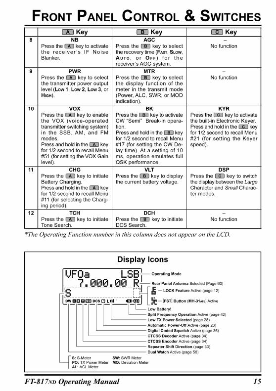
NBPress the key to activatethe receiver ’s IF NoiseBlanker.
PWRPress the key to selectthe transmitter power outputlevel (LOW 1, LOW 2, LOW 3, orHIGH).
VOXPress the key to enablethe VOX (voice-operatedtransmitter switching system)in the SSB, AM, and FMmodes.Press and hold in the keyfor 1/2 second to recall Menu#51 (for setting the VOX Gainlevel).
CHGPress the key to initiateBattery Charging.Press and hold in the keyfor 1/2 second to recall Menu#11 (for selecting the Charg-ing period).
TCHPress the key to initiateTone Search.
AGCPress the key to selectthe recovery time (FAST, SLOW,AUTO , o r O F F ) f o r t h ereceiver’s AGC system.
MTRPress the key to selectthe display function of themeter in the transmit mode(Power, ALC, SWR, or MODindication).
BKPress the key to activateCW “Semi” Break-in opera-tion.Press and hold in the keyfor 1/2 second to recall Menu#17 (for setting the CW De-lay time). At a setting of 10ms, operation emulates fullQSK performance.
VLTPress the key to displaythe current battery voltage.
DCHPress the key to initiateDCS Search.
–No function
–No function
KYRPress the key to activatethe built-in Electronic Keyer.Press and hold in the keyfor 1/2 second to recall Menu#21 (for setting the Keyerspeed).
DSPPress the key to switchthe display between the LargeCharacter and Small Charac-ter modes.
–No function
Key Key Key8
9
10
11
12
*The Operating Function number in this column does not appear on the LCD.
FRONT PANEL CONTROL & SWITCHES
Display Icons
16 FT-817ND Operating Manual
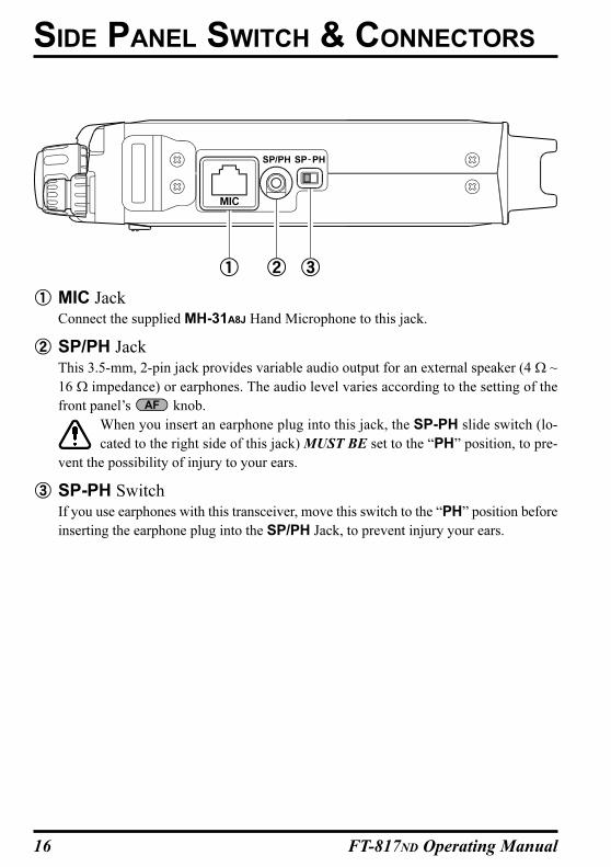
MIC JackConnect the supplied MH-31A8J Hand Microphone to this jack.
SP/PH JackThis 3.5-mm, 2-pin jack provides variable audio output for an external speaker (4 Ω ~
16 Ω impedance) or earphones. The audio level varies according to the setting of the
front panel’s knob.
When you insert an earphone plug into this jack, the SP-PH slide switch (lo-
cated to the right side of this jack) MUST BE set to the “PH” position, to pre-
vent the possibility of injury to your ears.
SP-PH SwitchIf you use earphones with this transceiver, move this switch to the “PH” position before
inserting the earphone plug into the SP/PH Jack, to prevent injury your ears.
SIDE PANEL SWITCH & CONNECTORS
17FT-817ND Operating Manual
REAR PANEL CONNECTORS
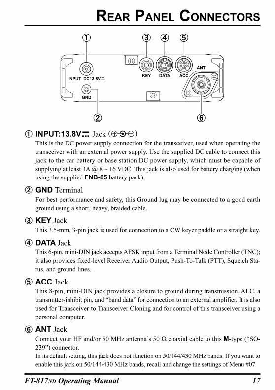
INPUT:13.8V Jack ( )
This is the DC power supply connection for the transceiver, used when operating the
transceiver with an external power supply. Use the supplied DC cable to connect this
jack to the car battery or base station DC power supply, which must be capable of
supplying at least 3A @ 8 ~ 16 VDC. This jack is also used for battery charging (when
using the supplied FNB-85 battery pack).
GND TerminalFor best performance and safety, this Ground lug may be connected to a good earth
ground using a short, heavy, braided cable.
KEY JackThis 3.5-mm, 3-pin jack is used for connection to a CW keyer paddle or a straight key.
DATA JackThis 6-pin, mini-DIN jack accepts AFSK input from a Terminal Node Controller (TNC);
it also provides fixed-level Receiver Audio Output, Push-To-Talk (PTT), Squelch Sta-
tus, and ground lines.
ACC JackThis 8-pin, mini-DIN jack provides a closure to ground during transmission, ALC, a
transmitter-inhibit pin, and “band data” for connection to an external amplifier. It is also
used for Transceiver-to Transceiver Cloning and for control of this transceiver using a
personal computer.
ANT JackConnect your HF and/or 50 MHz antenna’s 50 Ω coaxial cable to this M-type (“SO-
239”) connector.
In its default setting, this jack does not function on 50/144/430 MHz bands. If you want to
enable this jack on 50/144/430 MHz bands, recall and change the settings of Menu #07.
18 FT-817ND Operating Manual
Hi! I’m R.F. Radio, and I’m here to guide you through the fine points of the setup
and use of your new FT-817ND. I know your anxious to get on the air, but I
encourage you to read the “Operation” section of this manual as thoroughly as possible,
so you’ll get the most out of this fantastic new rig. Now. . .let’s get operating!
TURNING THE TRANSCEIVER ON AND OFF
1. To turn the transceiver on, press and hold in
the switch for one second.
2. To turn the transceiver off, again press and
hold in the switch for one second.
The one-second delay helps you avoid ac-
cidental switching on (or off) of DC power.
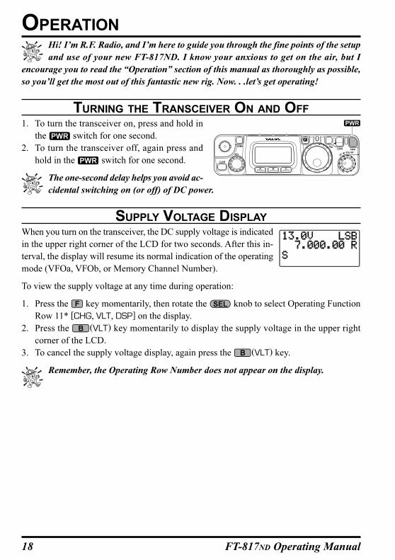
SUPPLY VOLTAGE DISPLAY
When you turn on the transceiver, the DC supply voltage is indicated
in the upper right corner of the LCD for two seconds. After this in-
terval, the display will resume its normal indication of the operating
mode (VFOa, VFOb, or Memory Channel Number).
To view the supply voltage at any time during operation:
1. Press the key momentarily, then rotate the knob to select Operating Function
Row 11* [CHG, VLT, DSP] on the display.
2. Press the (VLT) key momentarily to display the supply voltage in the upper right
corner of the LCD.
3. To cancel the supply voltage display, again press the (VLT) key.
Remember, the Operating Row Number does not appear on the display.
OPERATION
19FT-817ND Operating Manual
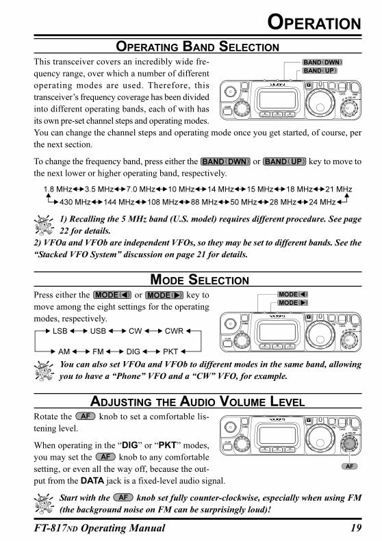
OPERATING BAND SELECTION
This transceiver covers an incredibly wide fre-
quency range, over which a number of different
operating modes are used. Therefore, this
transceiver’s frequency coverage has been divided
into different operating bands, each of with has
its own pre-set channel steps and operating modes.
You can change the channel steps and operating mode once you get started, of course, per
the next section.
To change the frequency band, press either the or key to move to
the next lower or higher operating band, respectively.
1) Recalling the 5 MHz band (U.S. model) requires different procedure. See page
22 for details.
2) VFOa and VFOb are independent VFOs, so they may be set to different bands. See the
“Stacked VFO System” discussion on page 21 for details.
MODE SELECTION
Press either the or key to
move among the eight settings for the operating
modes, respectively.
You can also set VFOa and VFOb to different modes in the same band, allowing
you to have a “Phone” VFO and a “CW” VFO, for example.
ADJUSTING THE AUDIO VOLUME LEVEL
Rotate the knob to set a comfortable lis-
tening level.
When operating in the “DIG” or “PKT” modes,
you may set the knob to any comfortable
setting, or even all the way off, because the out-
put from the DATA jack is a fixed-level audio signal.
Start with the knob set fully counter-clockwise, especially when using FM
(the background noise on FM can be surprisingly loud)!
OPERATION
20 FT-817ND Operating Manual
OPERATION
MENU QUICK START
Many aspects of this transceiver’s configuration may be customized using the convenient
“Menu” system, which allow you to configure many “set and forget” settings just the way
you want to. A full discussion of the Menu system beings on page 58; for now, here is a brief
discussion on how to change Menu settings:
1. Press and hold in the key for one second to enter the Menu mode.
2. Rotate the knob to recall the Menu item to be changed (for example, Menu #01,
which Enables or Disables the Automatic Repeater Shift on the 144 MHz band).
3. Rotate the knob to set this feature (in this example, the default setting is “EN-
ABLE,” so rotate the knob to set this feature to “DISABLE.”
4. Press and hold in the key for one second to save the new setting and exit to normal
operation.
If you have momentarily pressed the key to change an operating function,
press the key momentarily again (to clear the function indications for the ,
, keys) before engaging the Menu.
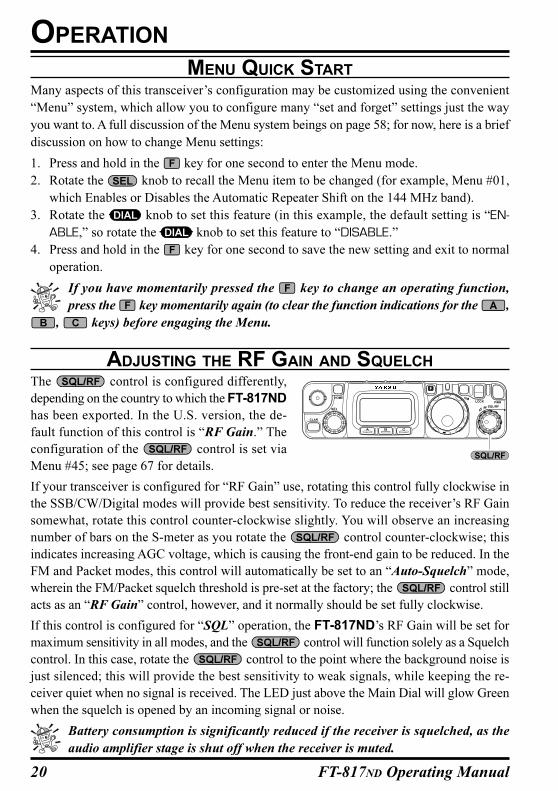
ADJUSTING THE RF GAIN AND SQUELCH
The control is configured differently,
depending on the country to which the FT-817ND
has been exported. In the U.S. version, the de-
fault function of this control is “RF Gain.” The
configuration of the control is set via
Menu #45; see page 67 for details.
If your transceiver is configured for “RF Gain” use, rotating this control fully clockwise in
the SSB/CW/Digital modes will provide best sensitivity. To reduce the receiver’s RF Gain
somewhat, rotate this control counter-clockwise slightly. You will observe an increasing
number of bars on the S-meter as you rotate the control counter-clockwise; this
indicates increasing AGC voltage, which is causing the front-end gain to be reduced. In the
FM and Packet modes, this control will automatically be set to an “Auto-Squelch” mode,
wherein the FM/Packet squelch threshold is pre-set at the factory; the control still
acts as an “RF Gain” control, however, and it normally should be set fully clockwise.
If this control is configured for “SQL” operation, the FT-817ND’s RF Gain will be set for
maximum sensitivity in all modes, and the control will function solely as a Squelch
control. In this case, rotate the control to the point where the background noise is
just silenced; this will provide the best sensitivity to weak signals, while keeping the re-
ceiver quiet when no signal is received. The LED just above the Main Dial will glow Green
when the squelch is opened by an incoming signal or noise.
Battery consumption is significantly reduced if the receiver is squelched, as the
audio amplifier stage is shut off when the receiver is muted.
21FT-817ND Operating Manual
OPERATION
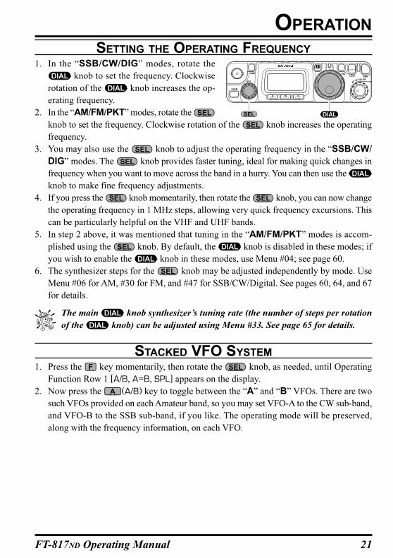
SETTING THE OPERATING FREQUENCY
1. In the “SSB/CW/DIG” modes, rotate the
knob to set the frequency. Clockwise
rotation of the knob increases the op-
erating frequency.
2. In the “AM/FM/PKT” modes, rotate the
knob to set the frequency. Clockwise rotation of the knob increases the operating
frequency.
3. You may also use the knob to adjust the operating frequency in the “SSB/CW/
DIG” modes. The knob provides faster tuning, ideal for making quick changes in
frequency when you want to move across the band in a hurry. You can then use the
knob to make fine frequency adjustments.
4. If you press the knob momentarily, then rotate the knob, you can now change
the operating frequency in 1 MHz steps, allowing very quick frequency excursions. This
can be particularly helpful on the VHF and UHF bands.
5. In step 2 above, it was mentioned that tuning in the “AM/FM/PKT” modes is accom-
plished using the knob. By default, the knob is disabled in these modes; if
you wish to enable the knob in these modes, use Menu #04; see page 60.
6. The synthesizer steps for the knob may be adjusted independently by mode. Use
Menu #06 for AM, #30 for FM, and #47 for SSB/CW/Digital. See pages 60, 64, and 67
for details.
The main knob synthesizer’s tuning rate (the number of steps per rotation
of the knob) can be adjusted using Menu #33. See page 65 for details.
STACKED VFO SYSTEM
1. Press the key momentarily, then rotate the knob, as needed, until Operating
Function Row 1 [A/B, A=B, SPL] appears on the display.
2. Now press the (A/B) key to toggle between the “A” and “B” VFOs. There are two
such VFOs provided on each Amateur band, so you may set VFO-A to the CW sub-band,
and VFO-B to the SSB sub-band, if you like. The operating mode will be preserved,
along with the frequency information, on each VFO.
22 FT-817ND Operating Manual
OPERATION
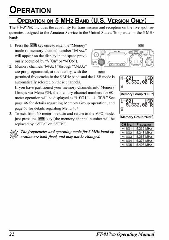
OPERATION ON 5 MHZ BAND (U.S. VERSION ONLY)The FT-817ND includes the capability for transmission and reception on the five spot fre-
quencies assigned to the Amateur Service in the United States. To operate on the 5 MHz
band:
1. Press the key once to enter the “Memory”
mode (a memory channel number “M-nnn”
will appear on the display in the space previ-
ously occupied by “VFOa” or “VFOb”).
2. Memory channels “M-601” through “M-605”
are pre-programmed, at the factory, with the
permitted frequencies in the 5 MHz band, and the USB mode is
automatically selected on these channels.
If you have partitioned your memory channels into Memory
Groups via Menu #34, the memory channel numbers for 60-
meter operation will be displayed as “l - 001” ~ “l - 005.” See
page 46 for details regarding Memory Group operation, and
page 65 for details regarding Menu #34.
3. To exit from 60-meter operatin and return to the VFO mode,
just press the key (the memory channel number will be
replaced by “VFOa” or “VFOb”).
The frequencies and operating mode for 5 MHz band op-
eration are both fixed, and may not be changed.
CLAR
ELS
F
V
LOCK PWR
SQL/RF
AF
M
SEL
V/M
CH No.
M-601
M-602
M-603
M-604
M-605
FREQUENCY
5.332 MHz
5.348 MHz
5.368 MHz
5.373 MHz
5.405 MHz
[Memory Group “OFF”]
[Memory Group “ON”]
23FT-817ND Operating Manual
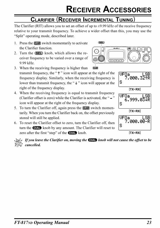
CLARIFIER (RECEIVER INCREMENTAL TUNING)The Clarifier (RIT) allows you to set an offset of up to ±9.99 kHz of the receive frequency
relative to your transmit frequency. To achieve a wider offset than this, you may use the
“Split” operating mode, described later.
1. Press the switch momentarily to activate
the Clarifier function.
2. Turn the knob, which allows the re-
ceiver frequency to be varied over a range of
9.99 kHz.
3. When the receiving frequency is higher than
transmit frequency, the “ ” icon will appear at the right of the
frequency display. Similarly, when the receiving frequency is
lower than transmit frequency, the “ ” icon will appear at the
right of the frequency display.
4. When the receiving frequency is equal to transmit frequency
(Clarifier offset is zero) while the Clarifier is activated, the “ ”
icon will appear at the right of the frequency display.
5. To turn the Clarifier off, again press the switch momen-
tarily. When you turn the Clarifier back on, the offset previously
stored will still be applied.
6. To reset the Clarifier offset to zero, turn the Clarifier off, then
turn the knob by any amount. The Clarifier will reset to
zero after the first “step” of the knob.
If you leave the Clarifier on, moving the knob will not cause the offset to be
cancelled.
RECEIVER ACCESSORIES
[TX<RX]
[TX>RX]
[TX=RX]
24 FT-817ND Operating Manual
RECEIVER ACCESSORIES
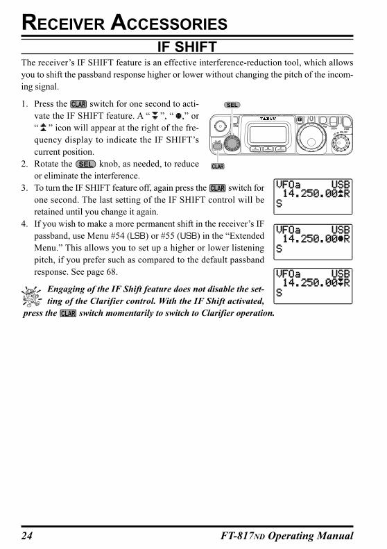
IF SHIFTThe receiver’s IF SHIFT feature is an effective interference-reduction tool, which allows
you to shift the passband response higher or lower without changing the pitch of the incom-
ing signal.
1. Press the switch for one second to acti-
vate the IF SHIFT feature. A “ ”, “ ,” or
“ ” icon will appear at the right of the fre-
quency display to indicate the IF SHIFT’s
current position.
2. Rotate the knob, as needed, to reduce
or eliminate the interference.
3. To turn the IF SHIFT feature off, again press the switch for
one second. The last setting of the IF SHIFT control will be
retained until you change it again.
4. If you wish to make a more permanent shift in the receiver’s IF
passband, use Menu #54 (LSB) or #55 (USB) in the “Extended
Menu.” This allows you to set up a higher or lower listening
pitch, if you prefer such as compared to the default passband
response. See page 68.
Engaging of the IF Shift feature does not disable the set-
ting of the Clarifier control. With the IF Shift activated,
press the switch momentarily to switch to Clarifier operation.
25FT-817ND Operating Manual
AGC (AUTOMATIC GAIN CONTROL)The receiver recovery time constant of the AGC system may be modified to match your
operating needs.
1. Press the key momentarily, then rotate the knob, as needed, until Operating
Function Row 8 [NB, AGC] appears on the display.
2. Press the (AGC) key to toggle the AGC recovery time constant among the following
selections:
“AGCauto” “AGCfast” “AGCslow” “AGCoff” “AGCauto” ……
where “AGCauto” represents “AGCfast” on CW and DIG(AFSK), and “AGCslow” on
the voice modes.
If “AGCoff” selected, the S-meter (which monitors AGC voltage) will cease to func-
tion.
NOISE BLANKER
The IF Noise Blanker may be useful in reducing or eliminating some types of impulse noise,
especially noise generated by automotive ignition systems.
1. Press the key momentarily, then rotate the knob, as needed, until Operating
Function Row 8 [NB, AGC] appears on the display.
2. Press the (NB) key to activate the Noise Blanker. The “” icon will appear at the
right of the “NB” indication.
3. Press the (NB) key again to turn the Noise Blanker off.
IPO (INTERCEPT POINT OPTIMIZATION)The IPO feature bypasses the receiver RF preamplifier, thereby eliminating the preamp’s
gain. This feature is not available on the 144 MHz and 430 MHz.
1. Press the key momentarily, then rotate the knob, as needed, until Operating
Function Row 7 [IPO, ATT, NAR] appears on the display.
2. Press the (IPO) key to bypass the receiver input preamplifier. The “” icon will
appear at the right of the “IPO” indication.
3. Press the (IPO) key once more to re-activate the preamp.
On the bands below 14 MHz, the input preamplifier is rarely necessary, and acti-
vation of the IPO feature will provide substantial protection against intermodulation
and other problems associated with strong signal input to the receiver. Rule of thumb: so
long as the S-meter is moving on background noise, additional front-end gain is not
necessary.
RECEIVER ACCESSORIES
26 FT-817ND Operating Manual
ATT (FRONT END ATTENUATOR)The Attenuator will reduce all signals (and noise) by 10 dB, and it may be used to make
reception more pleasant under extremely noisy conditions. This feature is not available on
the 144 MHz and 430 MHz.
1. Press the key momentarily, then rotate the knob, as needed, until Operating
Function Row 7 [IPO, ATT, NAR] appears on the display.
2. Press the (ATT) key to activate the Attenuator. The “” icon will appear at the right
of the “ATT” indication.
3. Press the (ATT) key once more to switch the Attenuator out of the receiver front end
circuit.
AM/FM DIALIn the AM and FM modes, the knob is locked out (via the setting of Menu #04) so as
to allow “channelized” tuning on these modes. To adjust the operating frequency, rotate the
knob.
If you wish to enable the knob for tuning in the AM and FM modes, change the setting
of Menu #04. See page 60 for details.
The “channelized” mode of tuning on AM and FM automatically rounds off the
frequency to the next “logical” step when you rotate the knob one “click” in
either direction. This eliminates the inconvenience of having to preset the frequency to
an “even” channel.
RECEIVER ACCESSORIES
27FT-817ND Operating Manual
AUTOMATIC POWER-OFF FEATURE
The APO feature helps conserve battery life by automatically turning the transceiver off
after a user-defined period of time within which there has been no dial or key activity. The
available selections for the time before power-off are 1 ~ 6 hours, as well as “APO Off.” The
default condition for the APO is OFF, and here is the procedure for activating it:
1. Press and hold the key for one second to enter the Menu mode.
2. Rotate the knob to recall Menu #08 (APO TIME).
3. Rotate the knob to select the desired time period after which the radio will auto-
matically shut down.
4. Press and hold the key for one second to save the new setting and exit to normal
operation.
Once you have programmed a time interval, the APO countdown timer will start whenever
some front panel action (tuning, transmission, etc.) is completed.
When the APO is activated, the “ ” icon will appear at the center bottom on the LCD. If
there is no action by you within the time interval programmed, the microprocessor will shut
down the radio automatically.
Just press and hold in the switch for one second to turn the transceiver back on after an
APO shutdown, as usual.
RECEIVER ACCESSORIES
28 FT-817ND Operating Manual
SSB TRANSMISSION
Basic Setup/Operation
1. Press the / key so as to select either SSB (LSB/USB) mode. If you
are operating on the 7 MHz or lower bands, select the LSB mode. If you are operating on
the 14 MHz or higher bands, select the USB mode.
2. Press the key momentarily, then rotate the knob, as needed, until Operating
Function Row 9 [PWR, MTR] appears on the display, then press the (MTR) key to
select the “ALC” meter function (“alc” will appear at the right side of the “MTR” icon).
3. Press the microphone’s PTT switch, and speak into the microphone in a normal voice
while watching the meter. The ideal audio input level to the transmitter from the micro-
phone will cause a few “segments” of indication on the ALC meter. Release the PTT
switch to return to receive mode.
4. If the ALC meter is too high, or too low, you may need to reset the Microphone Gain:
Press and hold in the key for one second to enter the Menu mode.
Rotate the knob to recall Menu #46 (SSB MIC).
Close the PTT switch, and while speaking into the microphone rotate the
knob until the proper ALC indication is achieved on voice peaks.
When done, press and hold in the key to save the new setting for the Microphone Gain.
The [TONE] switch on the back of the MH-31A8J microphone provides adjust-
ment of the microphone’s frequency response. Setting this switch to the “2” posi-
tion will roll off some of the bass response, resulting in improved “talk power” in many
instances. The “1” position is primarily used in countries like Japan, where vowel sounds
are of critical importance in conveying information; in Western languages, consonant
sounds (which are rich in high-frequency components) are frequently more important.
Adjusting the Transmitter Power Output
Four power levels are available on the FT-817ND: 5 Watts, 2.5 Watts, 1 Watt, and
0.5 Watt. When using Alkaline batteries or the supplied FNB-85 Ni-MH Battery
Pack, the microprocessor, detecting internal battery use, automatically sets the power
level to 2.5 Watts, which appears on the display as “ ”. If you set the power to five
watts, the power level icon is the same as for 2.5 Watt operation, but at 5 Watts the
icon is blinking. For 0.5 Watt, there is one “bar” to the right of the “L” in the power
icon, and for 1 Watt there are two “bars” displayed.
The power level is easy to change:
1. Press the key momentarily, then rotate the knob to select Operating
Function Row 9 [PWR, MTR].
2. Press the (PWR) key, as needed, to set the desired power level. The icon will
change, based on the power level you have set.
TRANSMITTER OPERATION
29FT-817ND Operating Manual
SSB TRANSMISSION
TRANSMITTER OPERATION
VOX Operation
The VOX system provides automatic transmit/receive switching based on voice input to the
microphone. With the VOX system enabled, you do not need to press the PTT switch in
order to transmit.
1. Press the key momentarily, then rotate the knob, as needed, until Operating
Function Row 10 [VOX, BK, KYR] appears on the display.
2. Press the (VOX) key to activate the VOX circuitry. The “” icon will appear at the
right of the “VOX” indication.
3. Without pressing the PTT switch, speak into the microphone in a normal voice level.
When you start speaking, the transmitter should be activated automatically. When you
finish speaking, the transceiver should return to the receive mode (after a short delay).
4. To cancel VOX and return to PTT operation., again press the (VOX) key. The “”
icon will disappear.
5. The VOX Gain may be adjusted, so as to prevent accidental transmitter activation in a
noisy environment. To adjust the VOX Gain:
While still in Operating Row 10 [VOX, BK, KYR], press and hold in the (VOX)
key for one second. This is a “hot key” feature which will instantly recall Menu #51
(VOX GAIN).
While speaking into the microphone, rotate the knob to the point where the
transmitter is quickly activated by your voice, without causing background noise to
activate the transmitter.
When you have selected the optimum setting, press and hold the key for one
second to save the new settings and return to normal operation.
6. The “Hang-Time” of the VOX system (the transmit-receive delay after the cessation of
speech) may also be adjusted via the Menu. The default delay is 1/2 second. To set a
different delay time:
Press and hold in the key for one second to activate the Menu mode.
Rotate the knob to select Menu #50 (VOX DELAY).
Rotate the knob while saying a brief syllable like “Ah” so as to set the desired
delay time.
When your adjustments are complete, press and hold in the key for one second to
save the new setting and return to normal operation.
The delay time for return to the receive mode is set independently on CW and voice
modes; for CW, use Menu #17 (see next section).
30 FT-817ND Operating Manual
CW TRANSMISSION
Operation using Straight Key/External Keying Device
When using a straight key, an external electronic keyer, or a computer-generated keying
device, please follow the instructions in this section.
1. Insert your key’s (three-conductor) plug into the rear-panel KEY jack.
2. Press the / key, as needed, to select one of the CW (CW/CWR)
modes.
The “CW” mode utilizes USB-side carrier injection, while the CWR (Reverse)
mode utilizes LSB-side injection.
3. Press the key momentarily, then then rotate the knob, as needed, until Operat-
ing Function Row 10 [VOX, BK, KYR] appears on the display.
4. Press the (BK) key, as needed, to activate “Semi Break-In” operation. The “” icon
will appear at the right of the “BK” indication.
5. The CW hang time can be adjusted using Menu #17 (CW DELAY). To adjust the CW
hang time:
Press and hold in the key for one second to enter the Menu mode.
Rotate the knob to select Menu #17 (CW DELAY).
Rotate the knob to select a longer or shorter delay time (default: 250 ms). This
transceiver was not expressly designed for “full QSK” operation, the minimum (10
ms) setting of this Menu item (CW DELAY) will be very close to full break-in perfor-
mance.
When done, press and hold in the key for one second to save the new setting and
exit to normal operation.
If you are already in Operating Function Row 10 [VOX, BK, KYR], pressing
and holding in the (BK) key for one second will instantly select Menu #17
(CW DELAY).
6. To practice your CW sending (without transmitting), press the (BK) key to make the
“” icon disappear. Now, pressing the key will cause the CW sidetone to be heard, but
your radio will not be transmitting a signal on the air.
7. You can adjust the CW sidetone volume level via Menu #44 (SIDETONE). To adjust the
CW sidetone volume level:
Press and hold in the key for one second to enter the Menu mode.
Rotate the knob to select Menu #44 (SIDETONE).
Rotate the knob to select a new level; on the arbitrary scale of “0” ~ “100,” the
default value is “50.”
When done, press and hold in the key for one second to save the new setting and
exit to normal operation.
TRANSMITTER OPERATION
31FT-817ND Operating Manual
8. You also can adjust the CW sidetone pitch using Menu #20 (CW PITCH). This adjust-
ment also controls the BFO offset (actual pitch of your transmitted signal relative to your
current receive frequency). To adjust the CW sidetone pitch:
Press and hold in the key for one second to enter the Menu mode.
Rotate the knob to select Menu #20 (CW PITCH).
Rotate the knob to select a new pitch tone/BFO offset. The available offset
range is 300 ~ 1000 Hz (default value is “700 Hz”).
When done, press and hold in the key for one second to save the new setting and
exit to normal operation.
Because the CW Pitch corresponds to the actual pitch of your transmitted signal,
the sidetone may be used in a “CW Spot” capacity. Just tune the pitch of the re-
ceived signal to the same pitch as that of your transceiver’s sidetone, and you will be
perfectly “zero beat” with the other station.
The FT-817ND can generate a “CW Spot” tone; just press and hold in the key while
in the CW mode.
TRANSMITTER OPERATION
CW TRANSMISSION
32 FT-817ND Operating Manual
Operation using Built-in Electronic Keyer
The built-in Electronic Keyer provides a convenient method of generating CW. The Elec-
tronic Keyer includes weight and speed adjustments.
1. Connect your keyer paddle’s cable to the KEY jack on the rear panel of the transceiver.
2. Press the / key, as needed, to select the CW (CW/CWR) mode.
3. Press the key momentarily, then rotate the knob, as needed, until Operating
Function Row 10 [VOX, BK, KYR] appears on the display.
4. Press the (KYR) key to activate the Electronic Keyer. The “” icon will appear at
the right of the “KYR” indication.
5. The Keyer speed may be adjusted using Menu #21 (CW SPEED). To adjust the Keyer
speed:
Press and hold in the key for one second to enter the Menu mode.
Rotate the knob to select Menu #21 (CW SPEED).
Press the knob if you wish to select display of “cpm” (characters per minute)
instead of “wpm” (words per minute). The “cpm” selection is based on the interna-
tional “PARIS” standard, which stipulates five characters per word.
Rotate the knob, while sending, to set the desired sending speed.
When done, press and hold in the key for one second to save the new setting and
exit to normal operation.
If you are already using Operating Function Row 10 [VOX, BK, KYR], press
and hold in the [C](KYR) key to switch instantly to Menu #21 (CW SPEED).
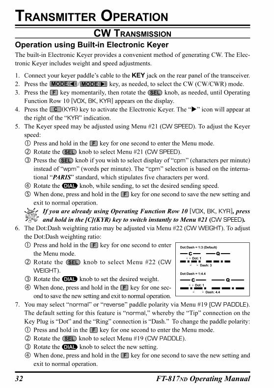
6. The Dot:Dash weighting ratio may be adjusted via Menu #22 (CW WEIGHT). To adjust
the Dot:Dash weighting ratio:
Press and hold in the key for one second to enter
the Menu mode.
Rotate the knob to select Menu #22 (CW
WEIGHT).
Rotate the knob to set the desired weight.
When done, press and hold in the key for one sec-
ond to save the new setting and exit to normal operation.
7. You may select “normal” or “reverse” paddle polarity via Menu #19 (CW PADDLE).
The default setting for this feature is “normal,” whereby the “Tip” connection on the
Key Plug is “Dot” and the “Ring” connection is “Dash.” To change the paddle polarity:
Press and hold in the key for one second to enter the Menu mode.
Rotate the knob to select Menu #19 (CW PADDLE).
Rotate the knob to select the new setting.
When done, press and hold in the key for one second to save the new setting and
exit to normal operation.
CW TRANSMISSION
TRANSMITTER OPERATION
33FT-817ND Operating Manual
TRANSMITTER OPERATION
FM TRANSMISSION
Basic Setup/Operation
1. Press the / key so as to select the FM mode.
2. Press the microphone’s PTT switch, and speak into the microphone in a normal voice.
3. Release the PTT switch to return to the receive mode.
4. If you get reports that your modulation level is too high or too low, you may need to
adjust the FM-mode microphone gain. The procedure is similar to that used on SSB:
Press the key momentarily, then rotate the knob, as needed, until Operat-
ing Function Row 9 [PWR, MTR] appears on the display, then press the (MTR)
key to select the “Deviation” meter function (“mod” will appear at the right side of
the “MTR” icon).
Press and hold in the key for one second to enter the Menu mode.
Rotate the knob to recall Menu #29 (FM MIC).
Increase or decrease the setting of the FM Mic Gain, depending on the level correc-
tion required, then press and hold the key to save the new setting.
Close the PTT switch, and while speaking into the microphone observe the meter
indication; the proper setting of the FM Mic Gain will produce five “bars” of indica-
tion on voice peaks, slightly less on lower levels of speech input.
When done, press and hold in the key to save the new setting for the FM-mode
microphone gain.
5. The VOX feature is operational during FM transmission. From Operating Function Row
10 [VOX, BK, KYR], press the (VOX) key to activate/deactivate VOX.
Repeater Operation
1. Press the key momentarily, then rotate the knob, as needed, until Operating
Function Row 4 [RPT, REV, TON] appears on the display.
2. Press the (RPT) key to activate repeater operation. One press of the (RPT) key
will have set the transceiver for “Minus Shift” operation. In this situation, you will ob-
serve the “–” indicator on the display. The transmitter frequency will be shifted down by
a default value so as to access the repeater input frequency. If your repeater uses a posi-
tive shift (instead of negative), press the (RPT) key again; the “+” indicator will
replace the “–” indicator on the display.
3. If the default repeater shift is not appropriate for your area, it may be set independently
for each band. To change the repeater shifts:
Press and hold the (RPT) key for one second. This instantly recalls Menu #42
(RPT SHFT).
Rotate the knob to select the desired shift frequency.
When done, press and hold in the key for one second to save the new setting and
exit to normal operation.
34 FT-817ND Operating Manual
4. Press the (TON) key to activate the CTCSS tone encoder, which provides a subaudible
repeater access tone. One press of the (TON) key will activate the CTCSS tone
encoder. In this situation, you will observe the “ ” indicator on the display. If you press
the (TON) key repeatedly, you will observe “ ” (CTCSS Encode/Decode),
followed by “ ” (Digital Coded Squelch, Encode/Decode). One additional press
will disable all repeater-access tone systems. See the next section for a discussion of
DCS operation.
5. If the default repeater access tone are not appropriate for your area, it also may be set
independently for each band. To change the repeater access tone:
Press and hold the (TON) key for one second. This instantly recalls Menu #48
(TONE FREQ).
Rotate the knob to select the desired CTCSS frequency.
When done, press and hold the key for one second so save the new setting and
exit to normal operation.
6. Set the transceiver’s receiver to the repeater output (downlink) frequency.
7. Close the PTT switch and speak into the microphone. You will observe that the transmit-
ted frequency has shifted according to the setting of the (RPT) key.
8. Release the PTT switch to return to the Receive mode.
9. With repeater shift activated, you can temporarily reverse the transmit and receive fre-
quencies by pressing the (REV) key. The “ ” icon will blink while “Reverse” shift
is activated. Press the (REV) key again to revert to the “Normal” shift direction.
10. When you are finished with repeater operation, you may wish to set the repeater shift to
simplex by pressing the (RPT) key, and disable the CTCSS or DCS tone by press-
ing the (TON) key.
11. On many transceiver versions, the Automatic Repeater Shift (ARS) feature is enabled at
the factory. This feature automatically activates the appropriate repeater shift when you
are operating inside the designated 144 MHz or 430 MHz FM repeater sub-bands in
your country. If you wish to change the settings for the ARS, use Menu #01 (144 ARS)
or Menu #02 (430 ARS) (see page 60).
If your local repeaters need a 1750-Hz burst tone for access (typically in Europe),
press and hold in the front panel’s key to transmit the burst tone.
FM TRANSMISSION
TRANSMITTER OPERATION
35FT-817ND Operating Manual
Tone Search Scanning
In operating situations where you don’t know the CTCSS tone being used by another
station, you can command the radio to listen to the incoming signal and scan in search
of the tone being used.
To scan for the CTCSS tone in use:
1. Press the key momentarily, then rotate the knob, as needed, until Oper-
ating Function Row 12 [TCH, DCH] appears on the display.
2. Press the (TCH) key to activate CTCSS Encoder/Decoder; (the “ ”
icon will appear on the display) and start scanning for the incoming CTCSS tone.
3. When the radio detects the correct tone, it will halt on that tone, and audio will be
allowed to pass.
4. Press and hold in the (TCH) key for one second; the CTCSS tone detected
will be stored as the “current” tone, so it may be used for memory storage pur-
poses, and you may now exit to normal operation.
FM TRANSMISSION
TRANSMITTER OPERATION
36 FT-817ND Operating Manual
DCS Operation
Another form of tone access control is Digital Code Squelch, or DCS. It is a newer, more
advanced tone system that is less susceptible to false triggering than CTCSS. A DCS En-
coder/Decoder is built into your transceiver, and operation is very similar to that described
above for CTCSS.
1. Set the desired DCS code via Menu #23 (DCS CODE).
2. Press the key momentarily, then rotate the knob, as needed, until Operating
Function Row 4 [RPT, REV, TON] appears on the display.
3. Press the (TON) key three times to activate the DCS Encoder/Decoder (the “ ”
icon will appear on the display). The receiver will remain muted until a matching DCS
code is received on an incoming signal.
4. Press the (TON) key once to cancel DCS operation (the “ ” icon will disappear).
DSC Search Scanning
In operating situations where you don’t know the DCS code being used by another
station, you can command the radio to listen to the incoming signal and scan in search
of the code being used.
To scan for the DCS code in use:
1. Press the key momentarily, then rotate the knob, as needed, until Oper-
ating Function Row 12 [TCH, DCH] appears on the display.
2. Press the (DCH) key to activate DCS Encoder/Decoder; (the “ ” icon
will appear on the display) and start scanning for the incoming DCS code.
3. When the radio detects the correct code, it will halt on that code, and audio will
be allowed to pass.
4. Press and hold in the (DCH) key for one second; the DCS code detected will
be stored as the “current” code, so it may be used for memory storage purposes,
and you may now exit to normal operation.
TRANSMITTER OPERATION
FM TRANSMISSION
37FT-817ND Operating Manual
ARTSTM (AUTO RANGE TRANSPOND SYSTEM) Operation
The ARTSTM system uses DCS signaling to inform you when you and another ARTS™-equipped
station are within communications range. This can be especially valuable during search-and-
rescue operations, as a base station can quickly use ARTS™ to alert a field unit that it is out of
range; the field unit can then move to a better location to re-establish communications.
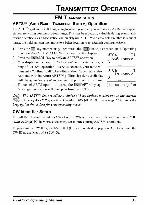
1. Press the key momentarily, then rotate the knob, as needed, until Operating
Function Row 6 [SSM, SCH, ART] appears on the display.
2. Press the (ART) key to activate ARTS™ operation.
3. Your display will change to “out range” to indicate the begin-
ning of ARTS™ operation. Every 25 seconds, your radio will
transmit a “polling” call to the other station. When that station
responds with its return ARTS™ polling signal, your display
will change to “in range” to confirm reception of the response.
4. To cancel ARTS operation, press the (ART) key again (the “out range” or
“in range” indication will disappear from the LCD).
The ARTS™ feature offers a choice of beep options to alert you to the current
status of ARTS™ operation. Use MENU #09 (ARTS BEEP) on page 61 to select the
beep option that is best for your operating needs.
CW Identifier Setup
The ARTS™ feature includes a CW identifier. When it is activated, the radio will send “DE
(your callsign) K” in Morse code every ten minutes during ARTS™ operation.
To program the CW IDer, use Menu #31 (ID), as described on page 64. And to activate the
CW IDer, use Menu #18 (CW ID).
FM TRANSMISSION
TRANSMITTER OPERATION
38 FT-817ND Operating Manual
DIGITAL MODE OPERATION (SSB-BASED AFSK)The FT-817ND provides extensive capability for digital mode operation on the HF, VHF,
and UHF bands. The use of AFSK (Audio Frequency-Shifted Keying) configurations allows
a wide variety of different communication modes to be utilized. The Menu provides for
specific digital mode selections, which include custom BFO offsets to optimize the receive
and transmit passbands for the mode selected.
Before beginning Digital operation, you need to define which Digital mode will be utilized.
To do this, use Menu #26 as follows (in this example, we will set up RTTY as the Digital
mode):
1. Press and hold in the key for one second to enter the Menu mode.
2. Rotate the knob to select Menu #26 (DIG MODE).
3. Rotate the knob to select “RTTY.”
4. Press and hold in the key for one second to save the new setting and exit.
Use this technique to set up any digital mode.
RTTY (Radio TeleType) Operation
The “RTTY” mode on the FT-817ND is based on LSB-side carrier injection, in accordance
with long-standing amateur practice. If you need USB-side injection for your application,
see the “User” mode discussion below.
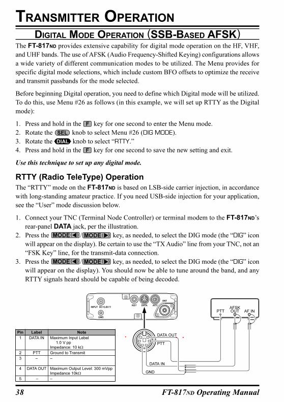
1. Connect your TNC (Terminal Node Controller) or terminal modem to the FT-817ND’s
rear-panel DATA jack, per the illustration.
2. Press the / key, as needed, to select the DIG mode (the “DIG” icon
will appear on the display). Be certain to use the “TX Audio” line from your TNC, not an
“FSK Key” line, for the transmit-data connection.
3. Press the / key, as needed, to select the DIG mode (the “DIG” icon
will appear on the display). You should now be able to tune around the band, and any
RTTY signals heard should be capable of being decoded.
TRANSMITTER OPERATION
Pin
1
2
3
4
5
Note
Maximum Input Lebel
1.0 V ppImpedance: 10 kΩ
Ground to Transmit
–
Maximum Output Level: 300 mVpp
Impedance 10kΩ
–
Label
DATA IN
PTT
–
DATA OUT
–
39FT-817ND Operating Manual
4. If the optional YF-122C 500 Hz filter has been installed, it may be used for RTTY work.
Recall Operating Function Row 7 [IPO, ATT, NAR] then press the (NAR) key to
engage the narrow filter.
5. To set up the transmit side, be sure that the Meter is set to monitor ALC voltage. If not,
press the key momentarily, then rotate the knob to select to select Operating
Function Row 9 [PWR, MTR], then press the (MTR) key so as to select metering of
ALC.
6. Press and hold in the key for 1/2 second to enter the MENU mode, then rotate the
knob to select Menu #25 (DIG MIC).
7. Following the instructions for your TNC’s software, activate the transmitter from the
computer keyboard; this should cause the AFSK output from the TNC to be sent to the
radio. While transmitting, view the ALC meter; a few “dots” of ALC indication should
be observed. If not, rotate the knob to adjust the AFSK level. Press and hold in the
key for one second to save the new AFSK level setting and return to normal opera-
tion. You are now ready for RTTY operation.
Because RTTY is a continuous-duty transmission mode, try to keep your transmission
short when running on battery power, so as to minimize current drain.
PSK31 Operation
Two dedicated PSK31 modes are available, one each for USB-side and LSB-side injection.
For BPSK work, the injection does not matter, but for QPSK the two working stations must
use the same sideband.
Connect the FT-817ND to your computer’s sound card or interface.
Setup for PSK31 operation is basically identical to that previously described for RTTY
operation. As before, use the “DIG” mode. However, in Menu #26, select “PSK31-L” (for
LSB injection) or “PSK31-U” (for USB injection. As with RTTY, Menu #25 may be used to
set the drive to the transmitter. And the YF-122C 500 Hz filter may also be utilized, as
described previously.
TRANSMITTER OPERATION
DIGITAL MODE OPERATION (SSB-BASED AFSK)
40 FT-817ND Operating Manual
“USER” Defined Digital Modes
Also provided in the FT-817ND are two convenient “USER” Digital modes, one each pro-
viding USB- and LSB-side injection, which may be used for SSTV, Fax, Pactor, and other
digital operating modes.
Here is an example involving the configuration of the USER mode for RTTY with USB-side
injection (as opposed to LSB injection, used in the default “RTTY” mode):
1. Use Menu #26 to set the Digital mode to “USER-U.”
2. Press the / key, as needed, to select the DIG mode (the “DIG” icon
will appear on the display).
3. Now use Menu #27 to configure the transceiver’s passband response. Once in the Menu
mode, rotate the knob to select Menu #27 (DIG SHIFT), and rotate the knob
to set the desired BFO offset (depending on how your TNC’s tones are set up). For
typical high-frequency tone use, a setting of about “+2100” will be a good starting
point.
4. Finally, depending on how you wish the display to respond, you may program in a corre-
sponding display shift, using Menu #24 (DIG DISP). Remember to press and hold in the
key for one second when exiting the Menu mode.
5. The setup of the AFSK drive level is identical to that described previously for RTTY
operation.
The USER-L and USER-U Digital modes should allow you to operate on any SSB-
based AFSK Digital mode. Note that the “PSK31” configurations will also work
well for many Digital operating situations.
DIGITAL MODE OPERATION (SSB-BASED AFSK)
TRANSMITTER OPERATION
41FT-817ND Operating Manual
PACKET (1200/9600 BPS FM) OPERATION
The FT-817ND is designed for operation on either 1200 bps or 9600 bps packet, and setup is
similar to that described previously for SSB-based modes. A separate Data input adjustment
is provided, allowing you to optimize the deviation on the FM Packet modes separately
from the SSB-based Digital modes. The RX-Data output lines are fixed-level outputs, not
affected by the setting of the AF Gain control.
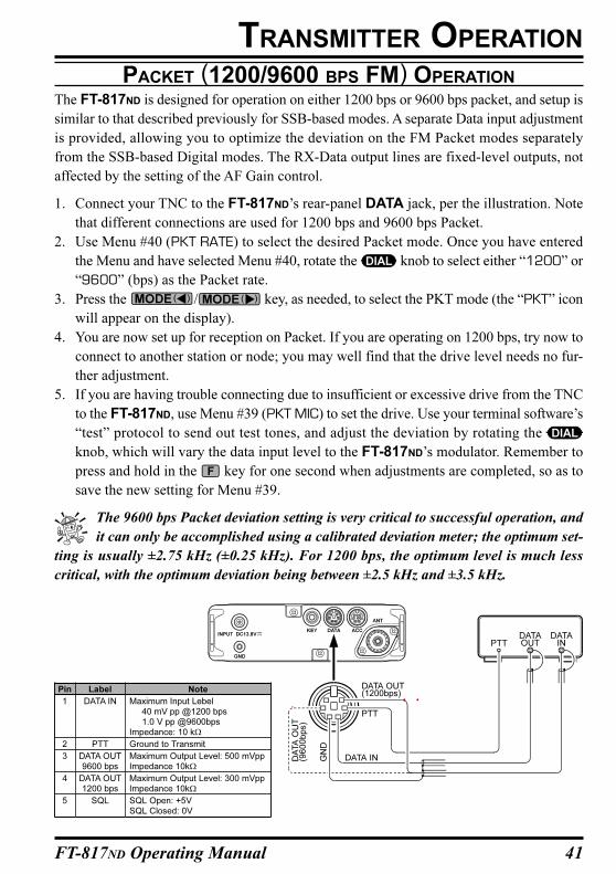
1. Connect your TNC to the FT-817ND’s rear-panel DATA jack, per the illustration. Note
that different connections are used for 1200 bps and 9600 bps Packet.
2. Use Menu #40 (PKT RATE) to select the desired Packet mode. Once you have entered
the Menu and have selected Menu #40, rotate the knob to select either “1200” or
“9600” (bps) as the Packet rate.
3. Press the / key, as needed, to select the PKT mode (the “PKT” icon
will appear on the display).
4. You are now set up for reception on Packet. If you are operating on 1200 bps, try now to
connect to another station or node; you may well find that the drive level needs no fur-
ther adjustment.
5. If you are having trouble connecting due to insufficient or excessive drive from the TNC
to the FT-817ND, use Menu #39 (PKT MIC) to set the drive. Use your terminal software’s
“test” protocol to send out test tones, and adjust the deviation by rotating the
knob, which will vary the data input level to the FT-817ND’s modulator. Remember to
press and hold in the key for one second when adjustments are completed, so as to
save the new setting for Menu #39.
The 9600 bps Packet deviation setting is very critical to successful operation, and
it can only be accomplished using a calibrated deviation meter; the optimum set-
ting is usually ±2.75 kHz (±0.25 kHz). For 1200 bps, the optimum level is much less
critical, with the optimum deviation being between ±2.5 kHz and ±3.5 kHz.
TRANSMITTER OPERATION
Pin
1
2
3
4
5
Note
Maximum Input Lebel
40 mV pp @1200 bps 1.0 V pp @9600bpsImpedance: 10 kΩ
Ground to Transmit
Maximum Output Level: 500 mVppImpedance 10kΩ
Maximum Output Level: 300 mVppImpedance 10kΩ
SQL Open: +5VSQL Closed: 0V
Label
DATA IN
PTT
DATA OUT9600 bps
DATA OUT1200 bps
SQL
42 FT-817ND Operating Manual
AM TRANSMISSION
The FT-817ND utilizes low-level amplitude modulation of an early stage for transmission
purposes. This capability is primarily provided for emergency use only, as low-power op-
eration typically utilizes more efficient transmission/reception modes.
The AM carrier level is preset to 1.5 Watts during alignment at the factory, and should not
require further adjustment. It is important to remember that AM transmission requires that
power must be distributed among the carrier and voice sidebands; therefore, if excessive
carrier power is used, there will be insufficient power available for the information-carrying
voice sidebands.
The AM microphone gain is preset at the factory to a value which typically provides good
audio. If you need to modify the microphone gain in the AM mode, use Menu #05 (AM
MIC). See page 60 for details.
SPLIT FREQUENCY OPERATION
This transceiver provides convenient split-frequency operation, using the VFO-A and VFO-
B, for DX working and other operating situations requiring unique split frequency pairs.
The example below will describe a typical split-frequency DX situation on the 20-meter
band, with a DX station transmitting on 14.025 MHz, listening 10 kHz higher in the band.
1. Set VFO-A to 14.035.00 MHz CW (DX station’s listening frequency).
2. Press the key momentarily, then rotate the knob, as needed, until Operating
Function Row [A/B, A=B, SPL].
3. Press the (A/B) key momentarily to select VFO-B.
4. Tune the VFO-B frequency to 14.025.00 MHz (DX station’s transmitting frequency).
5. Press the (SPL) key momentarily. The transceiver will now transmit using the VFO-
A frequency, and will receive using the VFO-B frequency. The “ ” icon will appear
on the display.
6. To listen to the pile-up calling the DX station (so as to align your frequency more closely
to that of the station being worked by the DX), press the (A/B) key to reverse the
VFOs. You will now be tuning in the vicinity of 14.035 MHz, and you can zero in on the
DX station’s listening frequency by tuning in on the station in QSO with the DX. Press
the (A/B) key again to return to reception on the DX station’s frequency.
7. Press the (SPL) key once more to cancel split operation; the “ ” icon will disap-
pear from the display.
TRANSMITTER OPERATION
43FT-817ND Operating Manual
TIME-OUT TIMER
Most often used on FM, the transmitter’s Time-Out Timer (TOT) feature disables the trans-
mitter after a user-defined period of transmission. This feature may be useful in preventing
a “stuck microphone” (accidental closure of the PTT switch) from causing interference to
other users, and it will also force you to keep your transmission short, thereby conserving
battery power.
To activate the Time-Out Timer:
1. Press and hold in the key for one second to enter the Menu mode.
2. Rotate the knob to recall Menu #49 (TOT TIME).
3. The default setting for this feature is “off.” Rotate the knob to set a new time-out
setting (from 1 minute to 20 minutes).
4. When you have made your selection, press and hold in the key for one second to save
the new setting and exit to normal operation.
WEATHERFAX MONITORING
Monitoring of HF WeatherFax broadcasts is easily accomplished using the FT-817ND.
1. Before proceeding, be certain that the WeatherFax demodulator is properly connected to
Pins 5 (DATA OUT 1200bps) and 2 (GND) of the rear panel DATA jack.
2. Set the transceiver to the VFO mode, and set the operating mode to “DIG,” setting Menu
#26 to PSK31-U, as described previously.
3. Now, select the operating frequency of the station transmitting the WeatherFax broad-
cast. Note that, in the USB mode, the frequency you should program onto the display is
typically 1.90 kHz below the station’s “assigned” frequency. Thus for a WeatherFax
station assigned to 8.682.0 MHz, tune to 8.680.1 MHz.
4. When the WeatherFax broadcast begins, no further operator intervention should be needed
from the transceiver standpoint. The audio level from the DATA jack on the rear of the
transceiver is fixed, and cannot be adjusted.
Fine adjustments in the gray-scale and the frame alignment are accomplished using the com-
puter and software connected to your WeatherFax demodulator.
TRANSMITTER OPERATION
44 FT-817ND Operating Manual
QMB CHANNEL
QMB Channel Storage
1. Tune in the desired frequency and set the operating mode and bandwidth. If this is an FM
channel, set up any required CTCSS/DCS and repeater shift configurations.
2. Press and hold in the key until a double “beep” is heard. The second beep provides
audible confirmation that the data has been stored into the QMB memory.
Pressing the (A/B) key momentarily while in Operating Function Row 3 [STO,
RCL, PMS] will also store a frequency into the QMB register.
QMB Channel Recall
1. Press the key momentarily, then rotate the knob, as needed, until Operating
Function Row 3 [STO, RCL, PMS] appears on the display.
2. Press the (RCL) key momentarily to recall the QMB memory. “QMB” will appear at
the upper right corner on the LCD.
3. Press the (RCL) key once more to return to the previous frequency (either a VFO
frequency or a Memory channel).
If you move the knob or knob while in the QMB mode, you can
change frequencies as if you were in a “VFO” mode. You also can change operat-
ing mode by pressing the or key. When this is done, the “MTQMB”
will appear in the display, where “MT” represents “Memory Tuning.” Press the (RCL)
key once more to return to the originally-stored QMB frequency.
MEMORY OPERATION
45FT-817ND Operating Manual
MEMORY OPERATION ON “REGULAR•EMEMORY CHANNELS
Normal Memory Storage
1. Tune in the desired frequency, and set the operating mode and bandwidth. If this is an
FM channel, set up any required CTCSS/DCS and repeater shift configurations. Stan-
dard (default) repeater shifts do not require you to utilize the “split” frequency memory
technique, described later.
2. Press the key momentarily, then rotate the knob, as needed, until Operating
Function Row 2 [MW, MC, TAG] appears on the display.
3. Press the (MW) key momentarily to enter the “Memory Check” mode, which is
used to find an unused memory channel. The frequency stored (if any) on the current
memory channel will be shown in the display.
4. Rotate the knob to select the channel number on which you wish to store the
current frequency data.
5. Press and hold in the (MW) key for one second until you hear a double beep; the
second beep confirms that the frequency information was successfully stored.
Split-Frequency Memory Storage
You can also store “Split” frequencies, such as when operating on a repeater system not utiliz-
ing a “standard” offset. This procedure may also be used for DX work on 7 MHz SSB, etc.
1. In the VFO mode, set the desired Receive frequency and mode.
2. Press the key momentarily, then rotate the knob, as needed, until Operating
Function Row 2 [MW, MC, TAG] appears on the display.
3. Press the (MW) key momentarily to enter the “Memory Check” mode, which is
used to find an unused memory channel. The frequency stored (if any) on the current
memory channel will be shown in the display.
4. Rotate the knob to select the channel on which you wish to store the receive
frequency data.
5. Press and hold in the (MW) key for one second until you hear a double beep, which
confirms that the Receive frequency data is now stored.
6. Now, set the desired Transmit frequency and mode on the VFO.
7. Press the (MW) key momentarily; do not rotate the knob!
8. While the “memory channel number” is blinking, press and hold in the PTT switch;
while holding it in, press and hold in the (MW) key for one second. The double
“beep” will confirm that independent Transmit frequency data is now stored. You may
now release the PTT switch.
In step 8 above, pressing the PTT switch does not activate the transmitter. It sim-
ply sends a signal to the microprocessor that an independent Transmit frequency
is being stored on the same channel as a previously-stored Receive frequency.
MEMORY OPERATION
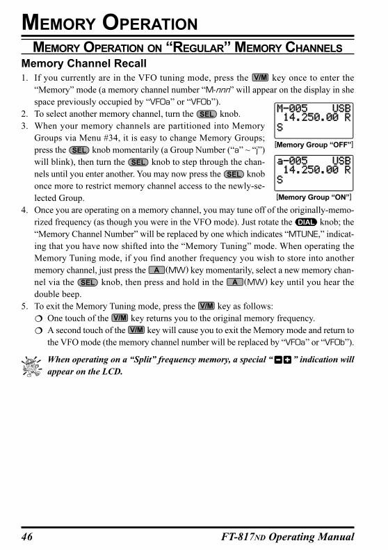
46 FT-817ND Operating Manual
Memory Channel Recall
1. If you currently are in the VFO tuning mode, press the key once to enter the
“Memory” mode (a memory channel number “M-nnn” will appear on the display in she
space previously occupied by “VFOa” or “VFOb”).
2. To select another memory channel, turn the knob.
3. When your memory channels are partitioned into Memory
Groups via Menu #34, it is easy to change Memory Groups;
press the knob momentarily (a Group Number (“a” ~ “j”)
will blink), then turn the knob to step through the chan-
nels until you enter another. You may now press the knob
once more to restrict memory channel access to the newly-se-
lected Group.
4. Once you are operating on a memory channel, you may tune off of the originally-memo-
rized frequency (as though you were in the VFO mode). Just rotate the knob; the
“Memory Channel Number” will be replaced by one which indicates “MTUNE,” indicat-
ing that you have now shifted into the “Memory Tuning” mode. When operating the
Memory Tuning mode, if you find another frequency you wish to store into another
memory channel, just press the (MW) key momentarily, select a new memory chan-
nel via the knob, then press and hold in the (MW) key until you hear the
double beep.
5. To exit the Memory Tuning mode, press the key as follows:
One touch of the key returns you to the original memory frequency.
A second touch of the key will cause you to exit the Memory mode and return to
the VFO mode (the memory channel number will be replaced by “VFOa” or “VFOb”).
When operating on a “Split” frequency memory, a special “ ” indication will
appear on the LCD.
MEMORY OPERATION ON “REGULAR” MEMORY CHANNELS
MEMORY OPERATION
[Memory Group “OFF”]
[Memory Group “ON”]
47FT-817ND Operating Manual
MEMORY OPERATION
Masking Memory
Frequency data stored on a memory channel can be deleted, if desired, from any memory
channel except channel “1.” The deletion process is not a “hard” erasure, so if you erase a
channel by mistake using this procedure, the memory channel contents can be recovered.
1. Press the key momentarily, then rotate the knob, as needed, until Operating
Function Row 2 [MW, MC, TAG] appears on the display.
2. Press the (MW) key momentarily, then rotate the knob to select the memory
channel to be deleted.
3. Press the (MC) key momentarily. The frequency display field on the LCD will go
blank, and the memory channel number will blink.
4. Wait about three seconds; when the memory channel number stops blinking, the data
will now be “masked” and will not be available for operation.
5. To restore the masked frequency data, repeat the above steps. However, if you store new
frequency information on a channel containing masked data, the masked data will be
over-written and lost.
6. Memory Channel 1 is used for Priority operation, and frequency information may only
be over-written (not masked) on this channel.
MEMORY OPERATION ON “REGULAR” MEMORY CHANNELS
48 FT-817ND Operating Manual
MEMORY OPERATION ON “HOME” CHANNEL MEMORIES
Four Special one-touch “Home” channels are available, for special frequencies you use
often. Either “simplex” or “split” frequency/mode data may be stored in the “Home” chan-
nel locations. Special “Home” channels are available for HF (any frequency between 1.8
and 29.7 MHz), 50 MHz, 144 MHz, and 430 MHz.
These memories may prove particularly useful for monitoring propagation beacons, provid-
ing one-touch recall of the beacon frequency for a quick check of band conditions.
HOME Channel Storage
1. Tune the desired frequency, and set the operating mode. If this is an FM channel, set up
any required CTCSS/DCS and repeater shift configurations.
2. Press the key momentarily, then rotate the knob, as needed, until Operating
Function Row 2 [MW, MC, TAG] appears on the display.
3. Press the (MW) key momentarily to enter the “Memory Check” mode.
4. Press and hold in the key for one second. This stores the frequency data into the
“Home” channel location. As usual, you will hear a double beep to confirm the success-
ful storage of the frequency data.
5. If you wish to store a “Split” frequency pair into the “Home” channel, store the Receive
frequency in steps 1 ~ 4 above. Now set the desired Transmit frequency.
6. Once more, press the (MW) key momentarily.
7. Press and hold in the microphone’s PTT switch; while holding the PTT switch, again
press and hold the key for one second. This stores the transmit frequency data into
the “Home” channel location.
HOME Channel Recall
1. Press the key momentarily to recall the Home Channel on the band group where
you currently are operating (HF, 50 MHz, 144 MHz, or 430 MHz). The “HOME” indica-
tion will appear on the display.
2. Press the key once more to return to the previously-used frequency (either a VFO
frequency or a memory channel).
MEMORY OPERATION
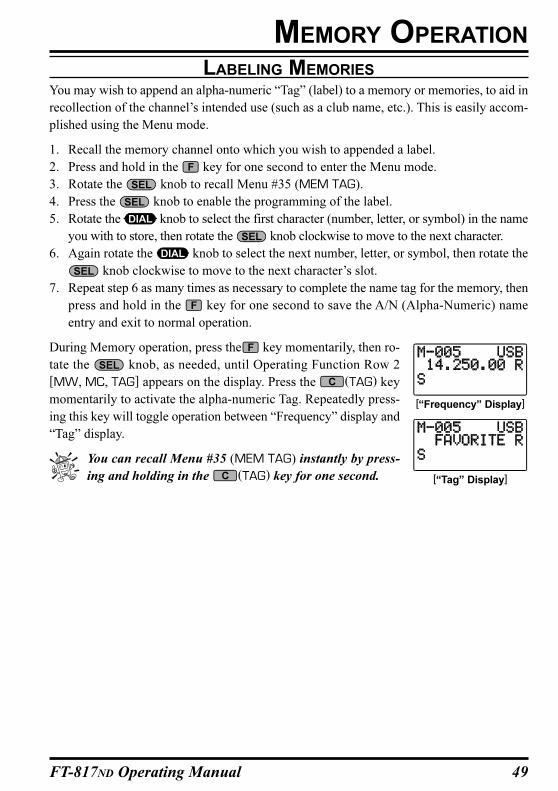
49FT-817ND Operating Manual
LABELING MEMORIES
You may wish to append an alpha-numeric “Tag” (label) to a memory or memories, to aid in
recollection of the channel’s intended use (such as a club name, etc.). This is easily accom-
plished using the Menu mode.
1. Recall the memory channel onto which you wish to appended a label.
2. Press and hold in the key for one second to enter the Menu mode.
3. Rotate the knob to recall Menu #35 (MEM TAG).
4. Press the knob to enable the programming of the label.
5. Rotate the knob to select the first character (number, letter, or symbol) in the name
you with to store, then rotate the knob clockwise to move to the next character.
6. Again rotate the knob to select the next number, letter, or symbol, then rotate the
knob clockwise to move to the next character’s slot.
7. Repeat step 6 as many times as necessary to complete the name tag for the memory, then
press and hold in the key for one second to save the A/N (Alpha-Numeric) name
entry and exit to normal operation.
During Memory operation, press the key momentarily, then ro-
tate the knob, as needed, until Operating Function Row 2
[MW, MC, TAG] appears on the display. Press the (TAG) key
momentarily to activate the alpha-numeric Tag. Repeatedly press-
ing this key will toggle operation between “Frequency” display and
“Tag” display.
You can recall Menu #35 (MEM TAG) instantly by press-
ing and holding in the (TAG) key for one second.
[“Frequency” Display]
[“Tag” Display]
MEMORY OPERATION
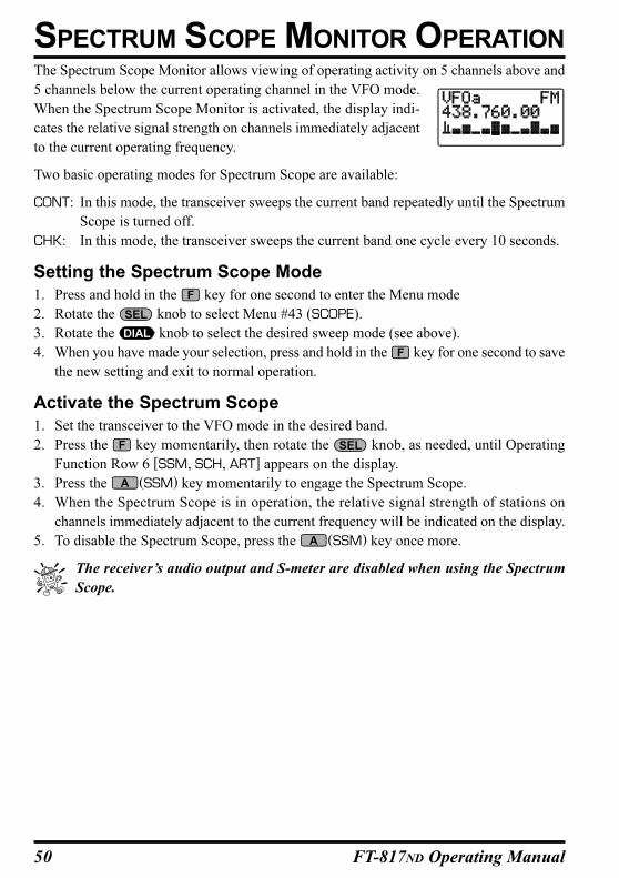
50 FT-817ND Operating Manual
The Spectrum Scope Monitor allows viewing of operating activity on 5 channels above and
5 channels below the current operating channel in the VFO mode.
When the Spectrum Scope Monitor is activated, the display indi-
cates the relative signal strength on channels immediately adjacent
to the current operating frequency.
Two basic operating modes for Spectrum Scope are available:
CONT: In this mode, the transceiver sweeps the current band repeatedly until the Spectrum
Scope is turned off.
CHK: In this mode, the transceiver sweeps the current band one cycle every 10 seconds.
Setting the Spectrum Scope Mode
1. Press and hold in the key for one second to enter the Menu mode
2. Rotate the knob to select Menu #43 (SCOPE).
3. Rotate the knob to select the desired sweep mode (see above).
4. When you have made your selection, press and hold in the key for one second to save
the new setting and exit to normal operation.
Activate the Spectrum Scope
1. Set the transceiver to the VFO mode in the desired band.
2. Press the key momentarily, then rotate the knob, as needed, until Operating
Function Row 6 [SSM, SCH, ART] appears on the display.
3. Press the (SSM) key momentarily to engage the Spectrum Scope.
4. When the Spectrum Scope is in operation, the relative signal strength of stations on
channels immediately adjacent to the current frequency will be indicated on the display.
5. To disable the Spectrum Scope, press the (SSM) key once more.
The receiver’s audio output and S-meter are disabled when using the Spectrum
Scope.
SPECTRUM SCOPE MONITOR OPERATION
51FT-817ND Operating Manual
The Smart SearchTM feature automatically stores frequencies where activity is encountered
on the current band. When Smart SearchTM is engaged, the transceiver quickly searches
above your current frequency, storing active frequencies as it goes (without stopping on
them even momentarily). These frequencies are stored in a special Smart SearchTM memory
bank, consisting of 50 memories. This feature available on the FM and AM modes.
The Smart Search™ feature is especially helpful when traveling, as you can instantly store
active FM repeater frequencies without having to look up the frequencies in a reference
book.
1. Set the knob to the point where background noise is silenced. A typical setting,
for effective Smart SearchTM operation, will be at 12 o’clock or slightly clockwise from
this position.
2. Set the VFO to the frequency on which you wish to begin the search (the Smart SearchTM
feature is available on the VFO mode only).
3. Press the key momentarily, then rotate the knob, as needed, until Operating
Function Row 6 [SSM, SCH, ART] appears on the display.
4. Now press the (SCH) key momentarily; the blinking “SRCH” indicator will appear
on the LCD, and the transceiver will sweep upward on the current band, loading chan-
nels on which it encounters a signal strong enough to open the squelch.
5. All channels where activity is present (up to 50 channels) will be loaded into the Smart
SearchTM memories. Whether or not all 50 memories are filled, the search will stop after
one sweep.
6. Now you can turn the knob to select from the just-stored Smart SearchTM memo-
ries. If you find frequencies you wish to store into a “regular” memory, just follow the
procedures described previously; just don’t press the (SCH) key while storing these
memories, because this will disable Smart Search™ operation (see step 7).
7. To disable Smart SearchTM operation, press the (SCH) key momentarily.
The Smart Search™ memories are so-called “soft” memories; they will be lost if
you initiate a new Smart SearchTM sweep of the band.
SMART SEARCH™ OPERATION
52 FT-817ND Operating Manual
This transceiver contains a wide variety of scanning capabilities. Whether you are in the
VFO mode or one of the memory modes, scanning operation is fundamentally identical in
all configurations, but with the following differences:
In the VFO mode, scanning causes the transceiver to sweep up or down the band,
pausing or halting on any signal encountered;
In the Memory mode, the scanner will scan the programmed memories, and can be
instructed to skip certain memories during scanning;
In the Programmable Memory Scan (PMS) mode, the scanner will scan the band
within user-programmed frequency limits.
Scanning Operation
1. Set the knob to the point where background noise is silenced. A typical setting,
for effective scanning operation, will be at 12 o’clock or slightly clockwise from this
position.
2. Set the transceiver into the operating configuration in which you wish to scan (VFO or
Memory; PMS will be described later).
8. Press the key momentarily, then rotate the knob, as needed, until Operating
Function Row [SCN, PRI, DW].
3. Press the (SCN) key momentarily to start upward scan (toward higher frequencies
or higher memory channel numbers).
4. Rotate the knob or knob counterclockwise to toggle the scanning direction
downward.
5. The scanner will now cause the transceiver to increment in the chosen direction until a
signal is detected. When a signal is encountered which opens the Squelch, In the FM/
AM modes, the scanner will pause until the signal disappears (at the end of the other
station’s transmission), at which point scanning will resume. While the transceiver is in
the “Pause” condition, the decimal points in the frequency display area will blink. See
“Scan-Resume Choices” on the next page for details of how to customize the resumption
of scanning, In the SSB/CW modes, the scanner will slow down (but doesn’t stop).
6. Press the PTT switch on the microphone to cancel scanning.
You may also press and hold in either the [UP] or [DWN] key on the microphone
for 1/2 second to initiate upward or downward scanning, respectively, if Menu #37
(MIC SCAN) is set to “ON.”
SCANNING OPERATION
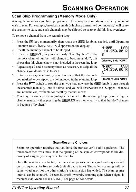
53FT-817ND Operating Manual
Scan Skip Programming (Memory Mode Only)
Among the memories you have programmed, there may be some stations which you do not
wish to scan. For example, broadcast signals (which are transmitted continuously) will cause
the scanner to stop, and such channels may be skipped so as to avoid this inconvenience.
To remove a channel from the scanning loop:
1. Press the key momentarily, then rotate the knob, as needed, until Operating
Function Row 2 [MW, MC, TAG] appears on the display.
2. Recall the memory channel to be skipped.
3. Press the (MC) key momentarily. The “hyphen” in the
memory channel number will change to become a “dot”; this
shows that this channel now is not included in the scanning loop.
4. Repeat steps 2 and 3 as many times as necessary to skip all the
channels you do not wish to scan.
5. Initiate memory scanning; you will observe that the channels
you marked to be skipped are not included in the scanning loop.
6. Press the PTT switch to stop the scan; you may now use the knob to step through
the channels manually - one at a time - and you will observe that the “Skipped” channels
are, nonetheless, available for recall by manual means.
7. You may restore a previously-skipped channel to the scanning loop by selecting the
channel manually, then pressing the (MC) key momentarily so that the “dot” changes
to become a “hyphen.”
SCANNING OPERATION
Scan-Resume Choices
Scanning operation requires that you have the transceiver’s audio squelched. The
transceiver then “assumes” that the opening of the squelch corresponds to the dis-
covery of a signal you may wish to listen to.
Once the scan has been halted, the transceiver pauses on the signal and stays locked
on its frequency for five seconds (default pause time). Thereafter, scanning will re-
sume whether or not the other station’s transmission has ended. The scan resume
interval can be set to 3/5/10 seconds, or off ( whereby scanning quits when a signal is
received) via Menu #41 (RESUME); see page 66 for details.
[Memory Skip “OFF”]
[Memory Skip “ON”]
54 FT-817ND Operating Manual
Programmable Memory Scan (PMS) Operation
To limit scanning (or tuning) within a particular frequency range, you can use the Program-
mable Memory Scanning (PMS) feature, which utilizes special-purpose memory pair (“M-
PL” and “M-PU”). The PMS feature is especially useful in helping you to observe any oper-
ating sub-band limits which apply to your Amateur license class.
PMS setup is simple to accomplish;
1. Store the upper and lower frequency limits of the desired range into the PMS memory
pair (“M-PL” and “M-PU”).
2. Press the key momentarily, then rotate the knob, as needed, until Operating
Function Row 3 [STO, RCL, PMS] appears on the display.
3. Press the (PMS) key. The “PMS” indication will appear at the upper left corner of
the LCD, signifying that the PMS feature is engaged. Tuning and scanning are now
limited within the range between the selected PMS memory pair, keeping operation in-
side this programmed range.
Example: Limit tuning & scanning to the frequency range 144.300 - 148.000 MHz
1. Press the key, as necessary, to recall the VFO mode. Tune the knob or
knob to 144.300 MHz.
2. Press the key momentarily, then rotate the knob, as needed, until Operating
Function Row 2 [MW, MC, TAG] appears on the display.
3. Press the (MW) key momentarily, then turn the knob to select memory chan-
nel “M-PL.”
4. Press and hold in the (MW) key for one second to write the VFO frequency into
“M-PL.”
5. Now, tune the knob or knob to 148.000 MHz).
6. Press the (MW) key momentarily, then turn the knob to select memory chan-
nel “M-PU.”
7. Press and hold the (MW) key for one second to write the VFO frequency into
“M-PU.”
8. Press the key momentarily, then rotate the knob one click clockwise to recall
Operating Function Row 3 [STO, RCL, PMS].
9. Press the (PMS) key momentarily. Tuning and scanning are now limited to the
144.300 ~ 148.000-MHz range until you press the key to return to memory or VFO
operation.
SCANNING OPERATION
55FT-817ND Operating Manual
Note
The frequency resolution for these sub-band limits is 100 kHz, although the channel
resolution of the sub-band limit memories in whatever you have selected as the cur-
rent step size. As a result, the frequencies stored in these special memories (M-PL and
M-PU) are both rounded down to the nearest 100 kHz for their roles as sub-band
limits. Therefore, in the above example, any frequency between 144.300 and 144.399
MHz may be used to store a lower tuning limit of “144.300 MHz” in memory M-PL.
SCANNING OPERATION
56 FT-817ND Operating Manual
DUAL WATCH OPERATIONDual Watch is similar, in some respects, to scanning. In Dual Watch, however, the trans-
ceiver monitors (squelched) on the VFO-A frequency while periodically checking VFO-B
for activity (or vice-versa). A typical example might be for you to set VFO-A to 50.110
MHz, watching for DX stations who might call CQ on that frequency, while periodically
checking 28.885 MHz for stations reporting band openings on 6 meters.
To activate Dual Watch:
1. Set up transmit and receive operation on VFO-A, establishing your primary monitoring
frequency. Set up the frequency to be checked periodically on VFO-B.
2. Recall VFO-A, then rotate the control until the background noise is just si-
lenced.
3. Press the key momentarily, then rotate the knob, as needed, until Operating
Function Row 5 [SCN, PRI, DW] appears on the display.
4. Press the (DW) key momentarily to activate Dual Watch operation (the “DW” icon
will appear at the bottom left corner of the LCD.
5. The transceiver will continue to monitor (squelched) on the current (VFO-A) frequency,
but every five seconds will switch briefly to VFO-B frequency, looking for activity.
6. If a station is detected on the VFO-B frequency, the transceiver will pause on the VFO-
B frequency (the decimal point in the frequency will blink).
7. Press the (DW) key again to cancel Dual Watch operation (the “DW” icon will
disappear).
Note that pressing the PTT switch on the microphone does not cancel Dual Watch
operation.
57FT-817ND Operating Manual
Section 97.401(d) of the regulations governing amateur radio in the United States permit
emergency amateur communications on the spot frequency of 5167.5 kHz by stations in (or
within 92.6 km of) the state of Alaska. This frequency is only to be used when the immediate
safety of human life and/or property are threatened, and is never to be used for routine
communications.
The FT-817ND includes the capability for transmission and reception on 5167.5 kHz under
such emergency conditions via the Menu system. To activate this feature:
1. Press and hold in the key for one second to activate the Menu mode.
2. Rotate the knob to select Menu #28 (EMERGENCY).
3. Rotate the knob to select “ON.”
4. Press and hold in the key to exit the Menu mode.
Emergency communication on this spot frequency is now possible:
Press the key, as necessary, to enter the Memory mode, then rotate the knob
to select the emergency channel (M-EMG), which is found between channels M-PU and
M-001.
Note that the receive-mode CLARIFIER functions normally while using this frequency, but
variation of the transmit frequency is not possible. Activation of Menu #28 does not enable
any other out-of-amateur-band capability on the transceiver. The full specifications of the
FT-817ND are not necessarily guaranteed on this frequency, but power output and receiver
sensitivity should be fully satisfactory for the purpose of emergency communication.
If you wish to disable operation on the Alaska Emergency Frequency, repeat the procedure
detailed above, but set Menu #28 to “OFF” in step 3 of the procedure.
In an emergency, note that a half-wave dipole cut for this frequency should be approxi-
mately 45’3” on each leg (90’6” total length).
Emergency operation on 5167.5 kHz is shared with the Alaska-Fixed Service. This trans-
ceiver is not authorized for operation, under the FCC’s Part 87, for aeronautical communi-
cations.
OPERATION ON ALASKA EMERGENCY FREQUENCY: 5167.5 KHZ (U.S. VERSION ONLY)
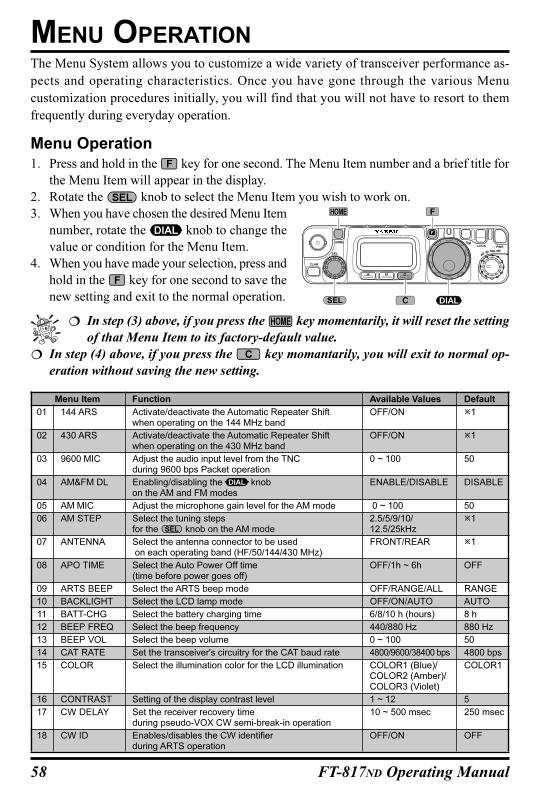
58 FT-817ND Operating Manual
Menu Item Function Available Values Default
01 144 ARS Activate/deactivate the Automatic Repeater Shift OFF/ON 1when operating on the 144 MHz band
02 430 ARS Activate/deactivate the Automatic Repeater Shift OFF/ON 1when operating on the 430 MHz band
03 9600 MIC Adjust the audio input level from the TNC 0 ~ 100 50during 9600 bps Packet operation
04 AM&FM DL Enabling/disabling the knob ENABLE/DISABLE DISABLEon the AM and FM modes
05 AM MIC Adjust the microphone gain level for the AM mode 0 ~ 100 50
06 AM STEP Select the tuning steps 2.5/5/9/10/ 1for the knob on the AM mode 12.5/25kHz
07 ANTENNA Select the antenna connector to be used FRONT/REAR 1 on each operating band (HF/50/144/430 MHz)
08 APO TIME Select the Auto Power Off time OFF/1h ~ 6h OFF(time before power goes off)
09 ARTS BEEP Select the ARTS beep mode OFF/RANGE/ALL RANGE
10 BACKLIGHT Select the LCD lamp mode OFF/ON/AUTO AUTO
11 BATT-CHG Select the battery charging time 6/8/10 h (hours) 8 h
12 BEEP FREQ Select the beep frequency 440/880 Hz 880 Hz
13 BEEP VOL Select the beep volume 0 ~ 100 50
14 CAT RATE Set the transceiver's circuitry for the CAT baud rate 4800/9600/38400 bps 4800 bps
15 COLOR Select the illumination color for the LCD illumination COLOR1 (Blue)/ COLOR1COLOR2 (Amber)/COLOR3 (Violet)
16 CONTRAST Setting of the display contrast level 1 ~ 12 5
17 CW DELAY Set the receiver recovery time 10 ~ 500 msec 250 msecduring pseudo-VOX CW semi-break-in operation
18 CW ID Enables/disables the CW identifier OFF/ON OFFduring ARTS operation
The Menu System allows you to customize a wide variety of transceiver performance as-
pects and operating characteristics. Once you have gone through the various Menu
customization procedures initially, you will find that you will not have to resort to them
frequently during everyday operation.
Menu Operation
1. Press and hold in the key for one second. The Menu Item number and a brief title for
the Menu Item will appear in the display.
2. Rotate the knob to select the Menu Item you wish to work on.
3. When you have chosen the desired Menu Item
number, rotate the knob to change the
value or condition for the Menu Item.
4. When you have made your selection, press and
hold in the key for one second to save the
new setting and exit to the normal operation.
In step (3) above, if you press the key momentarily, it will reset the setting
of that Menu Item to its factory-default value.
In step (4) above, if you press the key momantarily, you will exit to normal op-
eration without saving the new setting.
MENU OPERATION
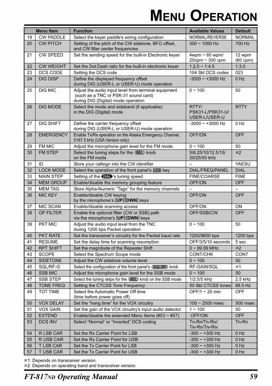
59FT-817ND Operating Manual
MENU OPERATION
1: Depends on transceiver version.2: Depends on operating band and transceiver version.
Menu Item Function Available Values Default
19 CW PADDLE Select the keyer paddle's wiring configuration NORMAL/REVERSE NORMAL
20 CW PITCH Setting of the pitch of the CW sidetone, BFO offset, 300 ~ 1000 Hz 700 Hzand CW filter center frequencies
21 CW SPEED Set the sending speed for the built-in Electronic keyer 4wpm ~ 60 wpm/ 12 wpm20cpm ~ 300 cpm (60 cpm)
22 CW WEIGHT Set the Dot:Dash ratio for the built-in electronic keyer 1:2.5 ~ 1:4.5 1:3.0
23 DCS CODE Setting the DCS code 104 Std DCS codes 023
24 DIG DISP Define the displayed frequency offset -3000 ~ +3000 Hz 0 Hzduring DIG (USER-L or USER-U) mode operation
25 DIG MIC Adjust the audio input level from terminal equipment 0 ~ 100 50 (such as a TNC or PSK-31 sound card)during DIG (Digital) mode operation
26 DIG MODE Select the mode and sideband (if applicable) RTTY/ RTTYin the DIG (Digital) mode PSK31-L/PSK31-U/
USER-L/USER-U
27 DIG SHIFT Define the carrier frequency offset -3000 ~ +3000 Hz 0 Hzduring DIG (USER-L or USER-U) mode operation
28 EMERGENCY Enable Tx/Rx operation on the Alaska Emergency Channel, OFF/ON OFF5167.5 kHz (USA Version only)
29 FM MIC Adjust the microphone gain level for the FM mode 0 ~ 100 50
30 FM STEP Select the tuning steps for the knob 5/6.25/10/12.5/15/ 2on the FM mode 20/25/50 kHz
31 ID Store your callsign into the CW identifier – YAESU
32 LOCK MODE Select the operation of the front panel’s key DIAL/FREQ/PANEL DIAL
33 MAIN STEP Setting of the ’s tuning speed FINE/COARSE FINE
34 MEM GROUP Enable/disable the memory grouping feature OFF/ON OFF
35 MEM TAG Store Alpha-Numeric “Tags” for the memory channels – –
36 MIC KEY Enable/disable CW keying OFF/ON OFFby the microphone’s [UP]/[DWN] keys
37 MIC SCAN Enable/disable scanning access OFF/ON ON
38 OP FILTER Enable the optional filter (CW or SSB) path OFF/SSB/CW OFFvia the microphone’s [UP]/[DWN] keys
39 PKT MIC Adjust the audio input level from the TNC 0 ~ 100 50during 1200 bps Packet operation
40 PKT RATE Set the transceiver’s circuitry for the Packet baud rate 1200/9600 bps 1200 bps
41 RESUME Set the delay time for scanning resumption OFF/3/5/10 seconds 5 sec
42 RPT SHIFT Set the magnitude of the Repeater Shift 0 ~ 99.99 MHz 2
43 SCOPE Select the Spectrum Scope mode CONT/CHK CONT
44 SIDETONE Adjust the CW sidetone volume level 0 ~ 100 50
45 SQL/RF-G Select the configuration of the front panel’s knob RF-GAIN/SQL 1
46 SSB MIC Adjust the microphone gain level for the SSB mode 0 ~ 100 50
47 SSB STEP Select the tuning steps for the knob on the SSB mode 1/2.5/5 kHz 2.5 kHz
48 TONE FREQ Setting the CTCSS Tone Frequency 50 Std CTCSS tones 88.5 Hz
49 TOT TIME Select the Automatic Power Off time OFF/1 ~ 20 min OFF(time before power goes off)
50 VOX DELAY Set the “hang time” for the VOX circuitry 100 ~ 2500 msec 500 msec
51 VOX GAIN Set the gain of the VOX circuitry's input audio detector 1 ~ 100 50
52 EXTEND Enable/disable the extended Menu Items (#53 ~ #57) OFF/ON OFF
53 DCS INV Select “Normal” or “Inverted” DCS coding Tn-Rn/Tn-Riv/ Tn-RnTiv-Rn/Tiv-Riv
54 R LSB CAR Set the Rx Carrier Point for LSB -300 ~ +300 Hz 0 Hz
55 R USB CAR Set the Rx Carrier Point for USB -300 ~ +300 Hz 0 Hz
56 T LSB CAR Set the Tx Carrier Point for LSB -300 ~ +300 Hz 0 Hz
57 T USB CAR Set the Tx Carrier Point for USB -300 ~ +300 Hz 0 Hz
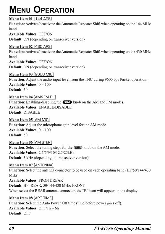
60 FT-817ND Operating Manual
Menu Item 01 [144 ARS]
Function: Activate/deactivate the Automatic Repeater Shift when operating on the 144 MHz
band.
Available Values: OFF/ON
Default: ON (depending on transceiver version)
Menu Item 02 [430 ARS]
Function: Activate/deactivate the Automatic Repeater Shift when operating on the 430 MHz
band.
Available Values: OFF/ON
Default: ON (depending on transceiver version)
Menu Item 03 [9600 MIC]
Function: Adjust the audio input level from the TNC during 9600 bps Packet operation.
Available Values: 0 ~ 100
Default: 50
Menu Item 04 [AM&FM DL]
Function: Enabling/disabling the knob on the AM and FM modes.
Available Values: ENABLE/DISABLE
Default: DISABLE
Menu Item 05 [AM MIC]
Function: Adjust the microphone gain level for the AM mode.
Available Values: 0 ~ 100
Default: 50
Menu Item 06 [AM STEP]
Function: Select the tuning steps for the knob on the AM mode.
Available Values: 2.5/5/9/10/12.5/25kHz
Default: 5 kHz (depending on transceiver version)
Menu Item 07 [ANTENNA]
Function: Select the antenna connector to be used on each operating band (HF/50/144/430
MHz).
Available Values: FRONT/REAR
Default: HF: REAR, 50/144/430 MHz: FRONT
When select the REAR antenna connector, the “R” icon will appear on the display
Menu Item 08 [APO TIME]
Function: Select the Auto Power Off time (time before power goes off).
Available Values: OFF/1h ~ 6h
Default: OFF
MENU OPERATION
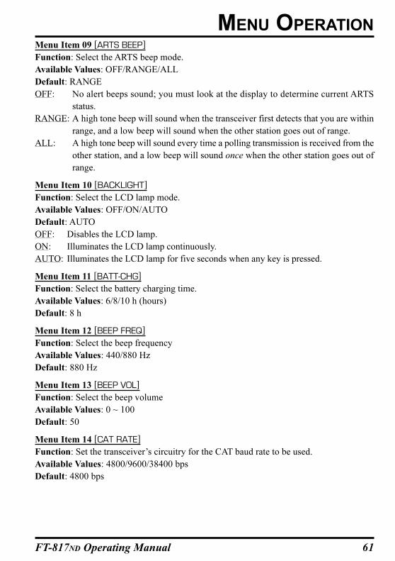
61FT-817ND Operating Manual
Menu Item 09 [ARTS BEEP]
Function: Select the ARTS beep mode.
Available Values: OFF/RANGE/ALL
Default: RANGE
OFF: No alert beeps sound; you must look at the display to determine current ARTS
status.
RANGE: A high tone beep will sound when the transceiver first detects that you are within
range, and a low beep will sound when the other station goes out of range.
ALL: A high tone beep will sound every time a polling transmission is received from the
other station, and a low beep will sound once when the other station goes out of
range.
Menu Item 10 [BACKLIGHT]
Function: Select the LCD lamp mode.
Available Values: OFF/ON/AUTO
Default: AUTO
OFF: Disables the LCD lamp.
ON: Illuminates the LCD lamp continuously.
AUTO: Illuminates the LCD lamp for five seconds when any key is pressed.
Menu Item 11 [BATT-CHG]
Function: Select the battery charging time.
Available Values: 6/8/10 h (hours)
Default: 8 h
Menu Item 12 [BEEP FREQ]
Function: Select the beep frequency
Available Values: 440/880 Hz
Default: 880 Hz
Menu Item 13 [BEEP VOL]
Function: Select the beep volume
Available Values: 0 ~ 100
Default: 50
Menu Item 14 [CAT RATE]
Function: Set the transceiver’s circuitry for the CAT baud rate to be used.
Available Values: 4800/9600/38400 bps
Default: 4800 bps
MENU OPERATION
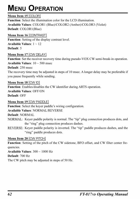
62 FT-817ND Operating Manual
Menu Item 15 [COLOR]
Function: Select the illumination color for the LCD illumination.
Available Values: COLOR1 (Blue)/COLOR2 (Amber)/COLOR3 (Violet)
Default: COLOR1(Blue)
Menu Item 16 [CONTRAST]
Function: Setting of the display contrast level.
Available Values: 1 ~ 12
Default: 5
Menu Item 17 [CW DELAY]
Function: Set the receiver recovery time during pseudo-VOX CW semi-break-in operation.
Available Values: 10 ~ 500 msec
Default: 250 msec
The recovery time may be adjusted in steps of 10 msec. A longer delay may be preferable if
you pause frequently while sending.
Menu Item 18 [CW ID]
Function: Enables/disables the CW identifier during ARTS operation.
Available Values: OFF/ON
Default: OFF
Menu Item 19 [CW PADDLE]
Function: Select the keyer paddle’s wiring configuration.
Available Values: NORMAL/REVERSE
Default: NORMAL
NORMAL: Keyer paddle polarity is normal. The “tip” plug connection produces dots, and
the “ring” plug connection produces dashes.
REVERSE: Keyer paddle polarity is inverted. The “tip” paddle produces dashes, and the
“ring” paddle produces dots.
Menu Item 20 [CW PITCH]
Function: Setting of the pitch of the CW sidetone, BFO offset, and CW filter center fre-
quencies.
Available Values: 300 ~ 1000 Hz
Default: 700 Hz
The CW pitch may be adjusted in steps of 50 Hz.
MENU OPERATION
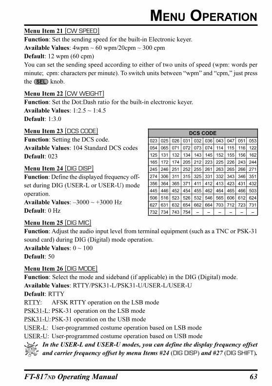
63FT-817ND Operating Manual
Menu Item 21 [CW SPEED]
Function: Set the sending speed for the built-in Electronic keyer.
Available Values: 4wpm ~ 60 wpm/20cpm ~ 300 cpm
Default: 12 wpm (60 cpm)
You can set the sending speed according to either of two units of speed (wpm: words per
minute; cpm: characters per minute). To switch units between “wpm” and “cpm,” just press
the knob.
Menu Item 22 [CW WEIGHT]
Function: Set the Dot:Dash ratio for the built-in electronic keyer.
Available Values: 1:2.5 ~ 1:4.5
Default: 1:3.0
Menu Item 23 [DCS CODE]
Function: Setting the DCS code.
Available Values: 104 Standard DCS codes
Default: 023
Menu Item 24 [DIG DISP]
Function: Define the displayed frequency off-
set during DIG (USER-L or USER-U) mode
operation.
Available Values: –3000 ~ +3000 Hz
Default: 0 Hz
Menu Item 25 [DIG MIC]
Function: Adjust the audio input level from terminal equipment (such as a TNC or PSK-31
sound card) during DIG (Digital) mode operation.
Available Values: 0 ~ 100
Default: 50
Menu Item 26 [DIG MODE]
Function: Select the mode and sideband (if applicable) in the DIG (Digital) mode.
Available Values: RTTY/PSK31-L/PSK31-U/USER-L/USER-U
Default: RTTY
RTTY: AFSK RTTY operation on the LSB mode
PSK31-L: PSK-31 operation on the LSB mode
PSK31-U:PSK-31 operation on the USB mode
USER-L: User-programmed costume operation based on LSB mode
USER-U: User-programmed costume operation based on USB mode
In the USER-L and USER-U modes, you can define the display frequency offset
and carrier frequency offset by menu Items #24 (DIG DISP) and #27 (DIG SHIFT).
MENU OPERATION
DCS CODE
023 025 026 031 032 036 043 047 051 053
054 065 071 072 073 074 114 115 116 122
125 131 132 134 143 145 152 155 156 162
165 172 174 205 212 223 225 226 243 244
245 246 251 252 255 261 263 265 266 271
274 306 311 315 325 331 332 343 346 351
356 364 365 371 411 412 413 423 431 432
445 446 452 454 455 462 464 465 466 503
506 516 523 526 532 546 565 606 612 624
627 631 632 654 662 664 703 712 723 731
732 734 743 754 – – – – – –
64 FT-817ND Operating Manual
Menu Item 27 [DIG SHIFT]
Function: Define the carrier frequency offset during DIG (USER-L or USER-U) mode
operation.
Available Values: –3000 ~ +3000 Hz
Default: 0 Hz
Menu Item 28 [EMERGENCY]: USA Version only
Function: Enable Tx/Rx operation on the Alaska Emergency Channel, 5167.5 kHz.
Available Values: OFF/ON
Default: OFF
When this Menu Item is set to “ON,” the spot frequency of 5167.5 kHz will be enabled. To
get to this frequency, use the knob to navigate; the Alaska Emergency Channel will be
found between the Memory channel “M-PU” and “M-001.”
Use of this frequency is restricted to amateurs operating in (or within 92.6 km of)
the U.S. State of Alaska, and it is to be used for emergency communications only
(involving the immediate protection of life or property).
Menu Item 29 [FM MIC]
Function: Adjust the microphone gain level for the FM mode.
Available Values: 0 ~ 100
Default: 50
Menu Item 30 [FM STEP]
Function: Select the tuning steps for the knob on the FM mode.
Available Values: 5/6.25/10/12.5/15/20/25/50 kHz
Default: 5 kHz (depends on operating band and transceiver version)
Menu Item 31 [ID]
Function: Store your callsign into the CW identifier. Up to eight characters may be stored.
The storage procedure is as follows:
1. Press the knob momentarily to initiate callsign storage (an “under-bar” will
appear below the first character location of the callsign).
2. Rotate the knob to select the first letter/number of your callsign, then rotate
the knob one click clockwise to save the first letter/number and move to the
next entry position.
3. Repeat the previous step as many times as necessary to complete your callsign.
4. Press the knob to save your completed callsign and exit.
Default: YAESU
MENU OPERATION
65FT-817ND Operating Manual
Menu Item 32 [LOCK MODE]
Function: Select the operation of the front panel’s key.
Available Values: DIAL/FREQ/PANEL
Default: DIAL
DIAL: Locks knob only
FREQ: Locks front panel keys and knobs related to frequency control (such as
and key, (A/B) key., etc.)
PANEL: Locks all front keys and knobs (except key and key)
Menu Item 33 [MAIN STEP]
Function: Setting of the knob’s tuning speed.
Available Values: FINE/COARSE
Default: FINE
You may choose between two speeds for the knob. Selecting “COARSE” doubles the
tuning rate compared to the default value.
Menu Item 34 [MEM GROUP]
Function: Enable/disable the memory grouping feature
Available Values: OFF/ON
Default: OFF
When this Menu Item is set to “ON,” the 200 “standard” memory channels are partitioned
into ten Memory Groups, each holding up to 20 memory channels.
Menu Item 35 [MEM TAG]
Function: Store Alpha-Numeric “Tags” for the memory channels.
Up to eight characters may be stored. The storage procedure is as follows:
1. Recall the memory channel on which you wish to append a label.
2. Recall this Menu Item [Menu #35 (MEM TAG)].
3. Press the knob momentarily to initiate storing of the Tag (an under-bar will
appear below the first character location).
4. Rotate the knob to select the first character (number, letter, or symbol) in the
name you with to store, then rotate the knob clockwise to move to the next
character.
5. Again rotate the knob to select the next number, letter, or symbol, then rotate
the knob clockwise to move to the next character’s slot.
6. Repeat step 5 as many times as necessary to complete the name tag for the memory.
7. Press the knob to save the A/N (Alpha-Numeric) Tag and exit.
MENU OPERATION
66 FT-817ND Operating Manual
Menu Item 36 [MIC KEY]
Function: Enable/disable CW keying by the microphone’s [UP]/[DWN] keys.
Available Values: OFF/ON
Default: OFF
When this Menu Item is set to “ON,” press the microphone’s [UP] key to send a “dot,” and
press the microphone’s [DWN] key to send a “dash” (while the built-in electronic keyer is
engaged).
Menu Item 37 [MIC SCAN]
Function: Enable/disable scanning access via the microphone’s [UP]/[DWN] keys.
Available Values: OFF/ON
Default: ON
Menu Item 38 [OP FILTER]
Function: Enable the optional filter (CW or SSB) path.
Available Values: OFF/SSB/CW
Default: OFF
After installing the optional filter, set this Menu Item to define the signal path corresponding
top the filter you have installed.
Menu Item 39 [PKT MIC]
Function: Adjust the audio input level from the TNC during 1200 bps Packet operation.
Available Values: 0 ~ 100
Default: 50
Menu Item 40 [PKT RATE]
Function: Set the transceiver’s circuitry for the Packet baud rate to be used.
Available Values: 1200/9600 bps
Default: 1200 bps
Menu Item 41 [RESUME]
Function: Set the delay time for scanning resumption.
Available Values: OFF/3/5/10 seconds
Default: 5 sec
When this Menu Item set to “OFF,” the scanner stops (without restarting) until you press the
(SCN) key (or the microphone’s [UP]/[DWN] keys).
Menu Item 42 [RPT SHIFT]
Function: Set the magnitude of the Repeater Shift.
Available Values: 0 ~ 99.99 MHz
Default: Depends on transceiver version, and the band in use.
Each band’s repeater shift (HF/50/144/430 MHz) may be set independently.
MENU OPERATION
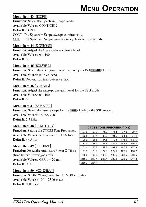
67FT-817ND Operating Manual
Menu Item 43 [SCOPE]
Function: Select the Spectrum Scope mode.
Available Values: CONT/CHK
Default: CONT
CONT: The Spectrum Scope sweeps continuously.
CHK: The Spectrum Scope sweeps one cycle every 10 seconds.
Menu Item 44 [SIDETONE]
Function: Adjust the CW sidetone volume level.
Available Values: 0 ~ 100
Default: 50
Menu Item 45 [SQL/RF-G]
Function: Select the configuration of the front panel’s knob.
Available Values: RF-GAIN/SQL
Default: Depends on transceiver version
Menu Item 46 [SSB MIC]
Function: Adjust the microphone gain level for the SSB mode.
Available Values: 0 ~ 100
Default: 50
Menu Item 47 [SSB STEP]
Function: Select the tuning steps for the knob on the SSB mode.
Available Values: 1/2.5/5 kHz
Default: 2.5 kHz
Menu Item 48 [TONE FREQ]
Function: Setting the CTCSS Tone Frequency.
Available Values: 50 Standard CTCSS tones
Default: 88.5 Hz
Menu Item 49 [TOT TIME]
Function: Select the Automatic Power Off time
(time before power goes off).
Available Values: OFF/1 ~ 20 min
Default: OFF
Menu Item 50 [VOX DELAY]
Function: Set the “hang time” for the VOX circuitry.
Available Values: 100 ~ 2500 msec
Default: 500 msec
MENU OPERATION
CTCSS TONE FREQUENCY (Hz)
67.0 69.3 71.9 74.4 77.0 79.7
82.5 85.4 88.5 91.5 94.8 97.4
100.0 103.5 107.2 110.9 114.8 118.8
123.0 127.3 131.8 136.5 141.3 146.2
151.4 156.7 159.8 162.2 165.5 167.9
171.3 173.8 177.3 179.9 183.5 186.2
189.9 192.8 196.6 199.5 203.5 206.5
210.7 218.1 225.7 229.1 233.6 241.8
250.3 254.1 – – – –
68 FT-817ND Operating Manual
Menu Item 51 [VOX GAIN]
Function: Set the gain of the VOX circuitry’s input audio detector.
Available Values: 1 ~ 100
Default: 50
Menu Item 52 [EXTEND]
Function: Enable/disable the extended Menu Items (#53 ~ #57).
Available Values: OFF/ON
Default: OFF
Menu Item 53 [DCS INV]
Function: Select “Normal” or “Inverted” DCS coding.
Available Values: Tn-Rn/Tn-Riv/Tiv-Rn/Tiv-Riv
Default: Tn-Rn
“n” = “normal
“iv” = “inverted”
Menu Item 54 [R LSB CAR]
Function: Set the Rx Carrier Point for LSB
Available Values: –300 ~ +300 Hz
Default: 0 Hz
Menu Item 55 [R USB CAR]
Function: Set the Rx Carrier Point for USB
Available Values: –300 ~ +300 Hz
Default: 0 Hz
Menu Item 56 [T LSB CAR]
Function: Set the Tx Carrier Point for LSB
Available Values: –300 ~ +300 Hz
Default: 0 Hz
Menu Item 57 [T USB CAR]
Function: Set the Tx Carrier Point for USB
Available Values: –300 ~ +300 Hz
Default: 0 Hz
MENU OPERATION
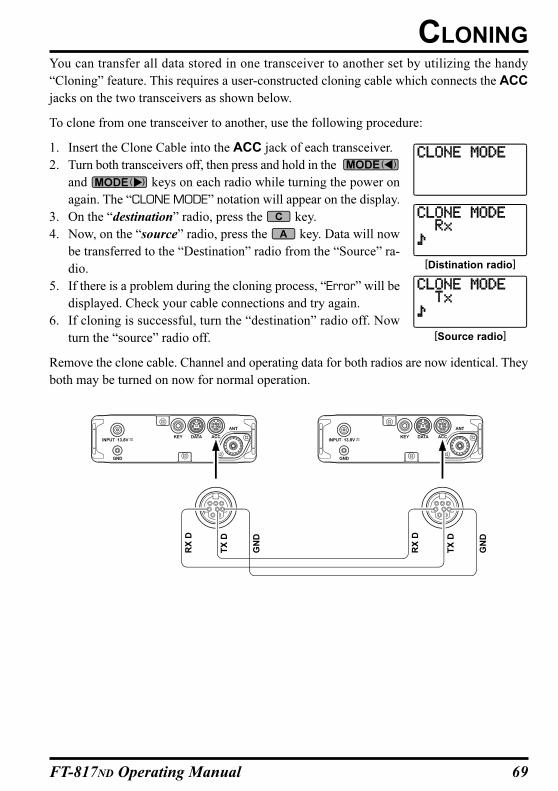
69FT-817ND Operating Manual
CLONINGYou can transfer all data stored in one transceiver to another set by utilizing the handy
“Cloning” feature. This requires a user-constructed cloning cable which connects the ACC
jacks on the two transceivers as shown below.
To clone from one transceiver to another, use the following procedure:
1. Insert the Clone Cable into the ACC jack of each transceiver.
2. Turn both transceivers off, then press and hold in the
and keys on each radio while turning the power on
again. The “CLONE MODE” notation will appear on the display.
3. On the “destination” radio, press the key.
4. Now, on the “source” radio, press the key. Data will now
be transferred to the “Destination” radio from the “Source” ra-
dio.
5. If there is a problem during the cloning process, “Error” will be
displayed. Check your cable connections and try again.
6. If cloning is successful, turn the “destination” radio off. Now
turn the “source” radio off.
Remove the clone cable. Channel and operating data for both radios are now identical. They
both may be turned on now for normal operation.
[Distination radio]
[Source radio]
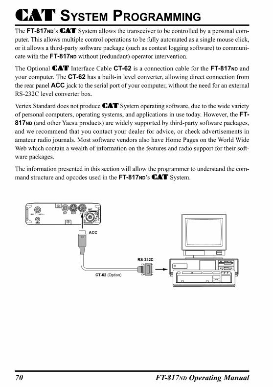
70 FT-817ND Operating Manual
The FT-817ND’s CAT System allows the transceiver to be controlled by a personal com-
puter. This allows multiple control operations to be fully automated as a single mouse click,
or it allows a third-party software package (such as contest logging software) to communi-
cate with the FT-817ND without (redundant) operator intervention.
The Optional CAT Interface Cable CT-62 is a connection cable for the FT-817ND and
your computer. The CT-62 has a built-in level converter, allowing direct connection from
the rear panel ACC jack to the serial port of your computer, without the need for an external
RS-232C level converter box.
Vertex Standard does not produce CAT System operating software, due to the wide variety
of personal computers, operating systems, and applications in use today. However, the FT-
817ND (and other Yaesu products) are widely supported by third-party software packages,
and we recommend that you contact your dealer for advice, or check advertisements in
amateur radio journals. Most software vendors also have Home Pages on the World Wide
Web which contain a wealth of information on the features and radio support for their soft-
ware packages.
The information presented in this section will allow the programmer to understand the com-
mand structure and opcodes used in the FT-817ND’s CAT System.
CAT SYSTEM PROGRAMMING
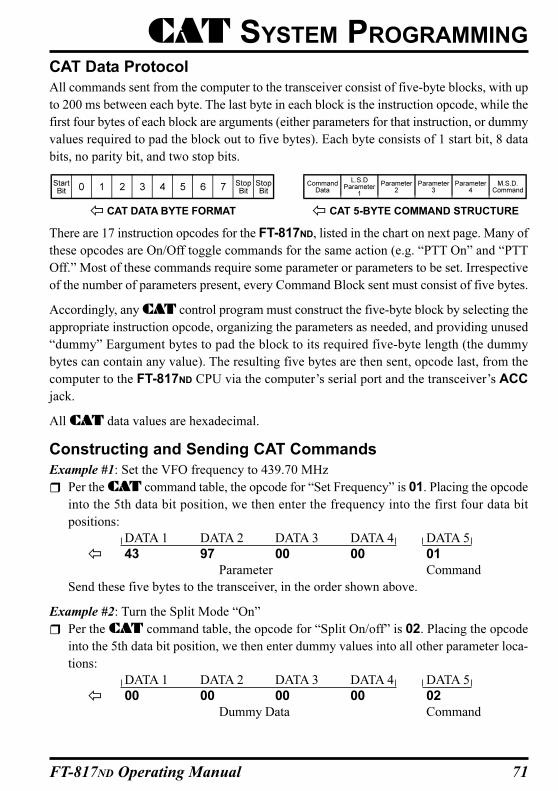
71FT-817ND Operating Manual
CAT SYSTEM PROGRAMMING
CAT Data Protocol
All commands sent from the computer to the transceiver consist of five-byte blocks, with up
to 200 ms between each byte. The last byte in each block is the instruction opcode, while the
first four bytes of each block are arguments (either parameters for that instruction, or dummy
values required to pad the block out to five bytes). Each byte consists of 1 start bit, 8 data
bits, no parity bit, and two stop bits.
There are 17 instruction opcodes for the FT-817ND, listed in the chart on next page. Many of
these opcodes are On/Off toggle commands for the same action (e.g. “PTT On” and “PTT
Off.” Most of these commands require some parameter or parameters to be set. Irrespective
of the number of parameters present, every Command Block sent must consist of five bytes.
Accordingly, any CAT control program must construct the five-byte block by selecting the
appropriate instruction opcode, organizing the parameters as needed, and providing unused
“dummy” Eargument bytes to pad the block to its required five-byte length (the dummy
bytes can contain any value). The resulting five bytes are then sent, opcode last, from the
computer to the FT-817ND CPU via the computer’s serial port and the transceiver’s ACC
jack.
All CAT data values are hexadecimal.
Constructing and Sending CAT Commands
Example #1: Set the VFO frequency to 439.70 MHz
Per the CAT command table, the opcode for “Set Frequency” is 01. Placing the opcode
into the 5th data bit position, we then enter the frequency into the first four data bit
positions:
DATA 1 DATA 2 DATA 3 DATA 4 DATA 5
43 97 00 00 01
Parameter Command
Send these five bytes to the transceiver, in the order shown above.
Example #2: Turn the Split Mode “On”
Per the CAT command table, the opcode for “Split On/off” is 02. Placing the opcode
into the 5th data bit position, we then enter dummy values into all other parameter loca-
tions:
DATA 1 DATA 2 DATA 3 DATA 4 DATA 5
00 00 00 00 02
Dummy Data Command
CAT DATA BYTE FORMAT CAT 5-BYTE COMMAND STRUCTURE
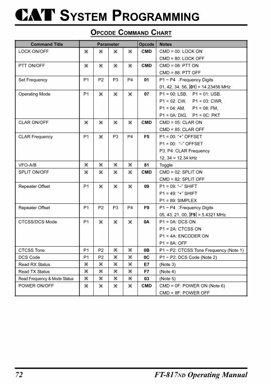
72 FT-817ND Operating Manual
Command Title
LOCK ON/OFF
PTT ON/OFF
Set Frequency
Operating Mode
CLAR ON/OFF
CLAR Frequency
VFO-A/B
SPLIT ON/OFF
Repeater Offset
Repeater Offset
CTCSS/DCS Mode
CTCSS Tone
DCS Code
Read RX Status
Read TX Status
Read Frequency & Mode Status
POWER ON/OFF
P1
P1
P1
P1
P1
P1
P1
P1
Notes
CMD = 00: LOCK ON
CMD = 80: LOCK OFF
CMD = 08: PTT ON
CMD = 88: PTT OFF
P1 ~ P4 Frequency Digits
01, 42, 34, 56, [01] = 14.23456 MHz
P1 = 00: LSB, P1 = 01: USB,
P1 = 02: CW, P1 = 03: CWR,
P1 = 04: AM, P1 = 08: FM,
P1 = 0A: DIG, P1 = 0C: PKT
CMD = 05: CLAR ON
CMD = 85: CLAR OFF
P1 = 00: “+” OFFSET
P1 ≠ 00: “–” OFFSET
P3, P4: CLAR Frequency
12, 34 = 12.34 kHz
Toggle
CMD = 02: SPLIT ON
CMD = 82: SPLIT OFF
P1 = 09: “–” SHIFT
P1 = 49: “+” SHIFT
P1 = 89: SIMPLEX
P1 ~ P4 Frequency Digits
05, 43, 21, 00, [F9] = 5.4321 MHz
P1 = 0A: DCS ON
P1 = 2A: CTCSS ON
P1 = 4A: ENCODER ON
P1 = 8A: OFF
P1 ~ P2: CTCSS Tone Frequency (Note 1)
P1 ~ P2: DCS Code (Note 2)
(Note 3)
(Note 4)
(Note 5)
CMD = 0F: POWER ON (Note 6)
CMD = 8F: POWER OFF
P2
P2
P2
P2
P3
P3
P3
P4
P4
P4
Opcode
CMD
CMD
01
07
CMD
F5
81
CMD
09
F9
0A
0B
0C
E7
F7
03
CMD
Parameter
OPCODE COMMAND CHART
CAT SYSTEM PROGRAMMING
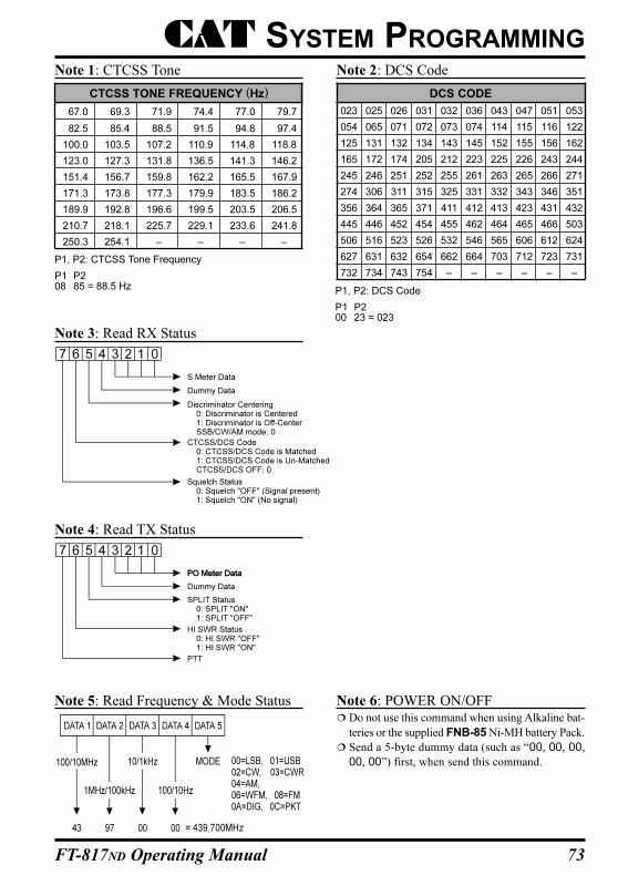
73FT-817ND Operating Manual
CTCSS TONE FREQUENCY (Hz)
67.0 69.3 71.9 74.4 77.0 79.7
82.5 85.4 88.5 91.5 94.8 97.4
100.0 103.5 107.2 110.9 114.8 118.8
123.0 127.3 131.8 136.5 141.3 146.2
151.4 156.7 159.8 162.2 165.5 167.9
171.3 173.8 177.3 179.9 183.5 186.2
189.9 192.8 196.6 199.5 203.5 206.5
210.7 218.1 225.7 229.1 233.6 241.8
250.3 254.1 – – – –
DCS CODE
023 025 026 031 032 036 043 047 051 053
054 065 071 072 073 074 114 115 116 122
125 131 132 134 143 145 152 155 156 162
165 172 174 205 212 223 225 226 243 244
245 246 251 252 255 261 263 265 266 271
274 306 311 315 325 331 332 343 346 351
356 364 365 371 411 412 413 423 431 432
445 446 452 454 455 462 464 465 466 503
506 516 523 526 532 546 565 606 612 624
627 631 632 654 662 664 703 712 723 731
732 734 743 754 – – – – – –
Note 1: CTCSS Tone Note 2: DCS Code
Note 3: Read RX Status
Note 4: Read TX Status
Note 5: Read Frequency & Mode Status Note 6: POWER ON/OFF Do not use this command when using Alkaline bat-
teries or the supplied FNB-85 Ni-MH battery Pack.
Send a 5-byte dummy data (such as “00, 00, 00,
00, 00”) first, when send this command.
CAT SYSTEM PROGRAMMING
P1, P2: CTCSS Tone Frequency
P1 P208 85 = 88.5 Hz P1, P2: DCS Code
P1 P200 23 = 023
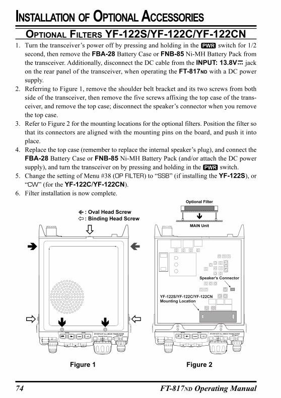
74 FT-817ND Operating Manual
OPTIONAL FILTERS YF-122S/YF-122C/YF-122CN1. Turn the transceiver’s power off by pressing and holding in the switch for 1/2
second, then remove the FBA-28 Battery Case or FNB-85 Ni-MH Battery Pack from
the transceiver. Additionally, disconnect the DC cable from the INPUT: 13.8V jack
on the rear panel of the transceiver, when operating the FT-817ND with a DC power
supply.
2. Referring to Figure 1, remove the shoulder belt bracket and its two screws from both
side of the transceiver, then remove the five screws affixing the top case of the trans-
ceiver, and remove the top case; disconnect the speaker’s connector when you remove
the top case.
3. Refer to Figure 2 for the mounting locations for the optional filters. Position the filter so
that its connectors are aligned with the mounting pins on the board, and push it into
place.
4. Replace the top case (remember to replace the internal speaker’s plug), and connect the
FBA-28 Battery Case or FNB-85 Ni-MH Battery Pack (and/or attach the DC power
supply), and turn the transceiver on by pressing and holding in the switch.
5. Change the setting of Menu #38 (OP FILTER) to “SSB” (if installing the YF-122S), or
“CW” (for the YF-122C/YF-122CN).
6. Filter installation is now complete.
INSTALLATION OF OPTIONAL ACCESSORIES
Figure 1 Figure 2
HF/VHF/UHF ALL MODE TRANSCEIVER
TRANSMIT/BUSY
BAND
DWN UP
MODE
YF-122S/YF-122CMounting Location
/YF-122CN
Speaker's Connector
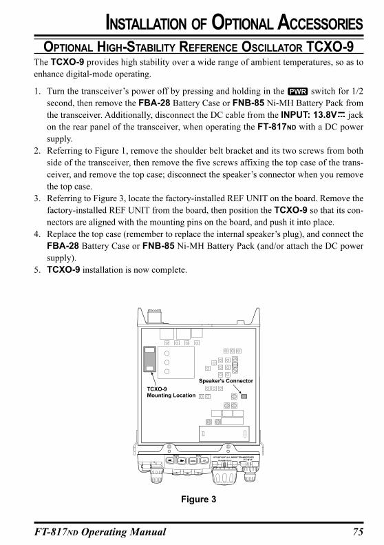
75FT-817ND Operating Manual
OPTIONAL HIGH-STABILITY REFERENCE OSCILLATOR TCXO-9The TCXO-9 provides high stability over a wide range of ambient temperatures, so as to
enhance digital-mode operating.
1. Turn the transceiver’s power off by pressing and holding in the switch for 1/2
second, then remove the FBA-28 Battery Case or FNB-85 Ni-MH Battery Pack from
the transceiver. Additionally, disconnect the DC cable from the INPUT: 13.8V jack
on the rear panel of the transceiver, when operating the FT-817ND with a DC power
supply.
2. Referring to Figure 1, remove the shoulder belt bracket and its two screws from both
side of the transceiver, then remove the five screws affixing the top case of the trans-
ceiver, and remove the top case; disconnect the speaker’s connector when you remove
the top case.
3. Referring to Figure 3, locate the factory-installed REF UNIT on the board. Remove the
factory-installed REF UNIT from the board, then position the TCXO-9 so that its con-
nectors are aligned with the mounting pins on the board, and push it into place.
4. Replace the top case (remember to replace the internal speaker’s plug), and connect the
FBA-28 Battery Case or FNB-85 Ni-MH Battery Pack (and/or attach the DC power
supply).
5. TCXO-9 installation is now complete.
INSTALLATION OF OPTIONAL ACCESSORIES
Figure 3
76 FT-817ND Operating Manual
Some or all transceiver settings can be reset to their factory-default states using one of the
following power-on routines:
+ POWER on: Reset all memories and following menu setting to factory-default.
Menu #06 (AM STEP), 23 (DCS CODE), 30 (FM STEP), 35 (MEM TAG), 42 (RPT SHIFT),
47 (SSB STEP), and 48 (TONE FREQ).
+ POWER on: Reset all menu setting (except following menu) to factory-default.
Menu #06 (AM STEP), 23 (DCS CODE), 30 (FM STEP), 35 (MEM TAG), 42 (RPT SHIFT),
47 (SSB STEP), and 48 (TONE FREQ).
+ POWER on: CPU master reset for all memories and menu setting.
POWER-ON MICROPROCESSOR RESET PROCEDURE
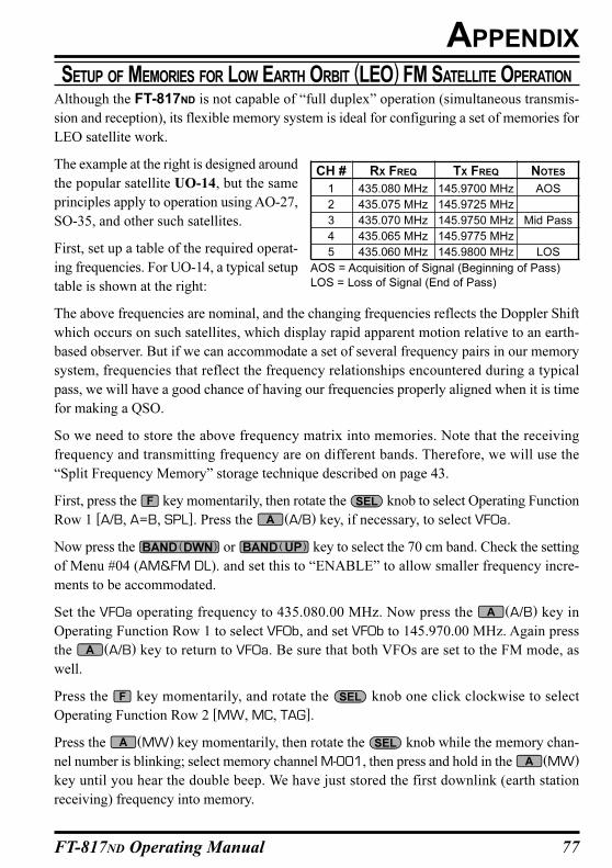
77FT-817ND Operating Manual
SETUP OF MEMORIES FOR LOW EARTH ORBIT (LEO) FM SATELLITE OPERATION
Although the FT-817ND is not capable of “full duplex” operation (simultaneous transmis-
sion and reception), its flexible memory system is ideal for configuring a set of memories for
LEO satellite work.
The example at the right is designed around
the popular satellite UO-14, but the same
principles apply to operation using AO-27,
SO-35, and other such satellites.
First, set up a table of the required operat-
ing frequencies. For UO-14, a typical setup
table is shown at the right:
The above frequencies are nominal, and the changing frequencies reflects the Doppler Shift
which occurs on such satellites, which display rapid apparent motion relative to an earth-
based observer. But if we can accommodate a set of several frequency pairs in our memory
system, frequencies that reflect the frequency relationships encountered during a typical
pass, we will have a good chance of having our frequencies properly aligned when it is time
for making a QSO.
So we need to store the above frequency matrix into memories. Note that the receiving
frequency and transmitting frequency are on different bands. Therefore, we will use the
“Split Frequency Memory” storage technique described on page 43.
First, press the key momentarily, then rotate the knob to select Operating Function
Row 1 [A/B, A=B, SPL]. Press the (A/B) key, if necessary, to select VFOa.
Now press the or key to select the 70 cm band. Check the setting
of Menu #04 (AM&FM DL). and set this to “ENABLE” to allow smaller frequency incre-
ments to be accommodated.
Set the VFOa operating frequency to 435.080.00 MHz. Now press the (A/B) key in
Operating Function Row 1 to select VFOb, and set VFOb to 145.970.00 MHz. Again press
the (A/B) key to return to VFOa. Be sure that both VFOs are set to the FM mode, as
well.
Press the key momentarily, and rotate the knob one click clockwise to select
Operating Function Row 2 [MW, MC, TAG].
Press the (MW) key momentarily, then rotate the knob while the memory chan-
nel number is blinking; select memory channel M-001, then press and hold in the (MW)
key until you hear the double beep. We have just stored the first downlink (earth station
receiving) frequency into memory.
APPENDIX
AOS = Acquisition of Signal (Beginning of Pass)
LOS = Loss of Signal (End of Pass)
CH #
1
2
3
4
5
RX FREQ
435.080 MHz
435.075 MHz
435.070 MHz
435.065 MHz
435.060 MHz
TX FREQ
145.9700 MHz
145.9725 MHz
145.9750 MHz
145.9775 MHz
145.9800 MHz
NOTES
AOS
Mid Pass
LOS
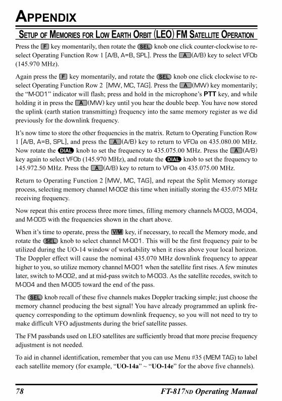
78 FT-817ND Operating Manual
Press the key momentarily, then rotate the knob one click counter-clockwise to re-
select Operating Function Row 1 [A/B, A=B, SPL]. Press the (A/B) key to select VFOb
(145.970 MHz).
Again press the key momentarily, and rotate the knob one click clockwise to re-
select Operating Function Row 2 [MW, MC, TAG]. Press the (MW) key momentarily;
the “M-001” indicator will flash; press and hold in the microphone’s PTT key, and while
holding it in press the (MW) key until you hear the double beep. You have now stored
the uplink (earth station transmitting) frequency into the same memory register as we did
previously for the downlink frequency.
It’s now time to store the other frequencies in the matrix. Return to Operating Function Row
1 [A/B, A=B, SPL], and press the (A/B) key to return to VFOa on 435.080.00 MHz.
Now rotate the knob to set the frequency to 435.075.00 MHz. Press the (A/B)
key again to select VFOb (145.970 MHz), and rotate the knob to set the frequency to
145.972.50 MHz. Press the (A/B) key to return to VFOa on 435.075.00 MHz.
Return to Operating Function 2 [MW, MC, TAG], and repeat the Split Memory storage
process, selecting memory channel M-002 this time when initially storing the 435.075 MHz
receiving frequency.
Now repeat this entire process three more times, filling memory channels M-003, M-004,
and M-005 with the frequencies shown in the chart above.
When it’s time to operate, press the key, if necessary, to recall the Memory mode, and
rotate the knob to select channel M-001. This will be the first frequency pair to be
utilized during the UO-14 window of workability when it rises above your local horizon.
The Doppler effect will cause the nominal 435.070 MHz downlink frequency to appear
higher to you, so utilize memory channel M-001 when the satellite first rises. A few minutes
later, switch to M-002, and at mid-pass switch to M-003. As the satellite recedes, switch to
M-004 and then M-005 toward the end of the pass.
The knob recall of these five channels makes Doppler tracking simple; just choose the
memory channel producing the best signal! You have already programmed an uplink fre-
quency corresponding to the optimum downlink frequency, so you will not need to try to
make difficult VFO adjustments during the brief satellite passes.
The FM passbands used on LEO satellites are sufficiently broad that more precise frequency
adjustment is not needed.
To aid in channel identification, remember that you can use Menu #35 (MEM TAG) to label
each satellite memory (for example, “UO-14a” ~ “UO-14e” for the above five channels).
SETUP OF MEMORIES FOR LOW EARTH ORBIT (LEO) FM SATELLITE OPERATION
APPENDIX
79FT-817ND Operating Manual
SETUP OF MEMORIES FOR LOW EARTH ORBIT (LEO) FM SATELLITE OPERATION
APPENDIX
A complete set of frequencies may be stored for each LEO satellite you wish to utilize, and
once configured, the FT-817ND provides a flexible and easy-to-use earth station capability
for these popular satellites.
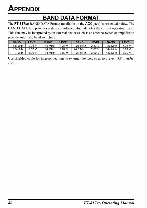
80 FT-817ND Operating Manual
APPENDIX
LEVEL
0.33 V
0.67 V
1.00 V
BAND
1.8 MHz
3.5 MHz
7 MHz
BAND
10 MHz
14 MHz
18 MHz
BAND
21 MHz
24.5 MHz
28 MHz
BAND
50 MHz
144 MHz
430 MHz
LEVEL
3.33 V
3.67 V
4.00 V
LEVEL
1.33 V
1.67 V
2.00 V
LEVEL
2.33 V
2.67 V
3.00 V
BAND DATA FORMATThe FT-817ND BAND DATA Format (available on the ACC jack) is presented below. The
BAND DATA line provides a stepped voltage, which denotes the current operating band.
This data may be interpreted by an external device (such as an antenna switch or amplifier)to
provide automatic band switching.
Use shielded cable for interconnections to external devices, so as to prevent RF interfer-
ence.
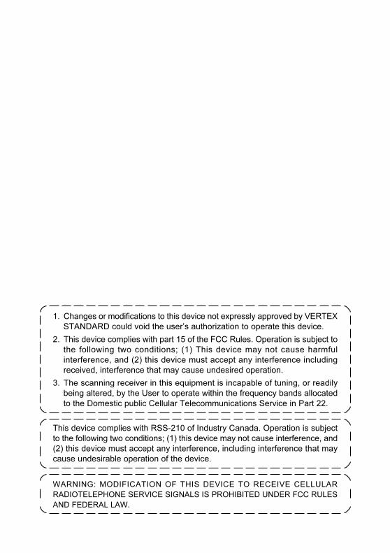
1. Changes or modifications to this device not expressly approved by VERTEX
STANDARD could void the user’s authorization to operate this device.
2. This device complies with part 15 of the FCC Rules. Operation is subject to
the following two conditions; (1) This device may not cause harmful
interference, and (2) this device must accept any interference including
received, interference that may cause undesired operation.
3. The scanning receiver in this equipment is incapable of tuning, or readily
being altered, by the User to operate within the frequency bands allocated
to the Domestic public Cellular Telecommunications Service in Part 22.
This device complies with RSS-210 of Industry Canada. Operation is subject
to the following two conditions; (1) this device may not cause interference, and
(2) this device must accept any interference, including interference that may
cause undesirable operation of the device.
WARNING: MODIFICATION OF THIS DEVICE TO RECEIVE CELLULAR
RADIOTELEPHONE SERVICE SIGNALS IS PROHIBITED UNDER FCC RULES
AND FEDERAL LAW.

Copyright 2004
VERTEX STANDARD CO., LTD.
All rights reserved.
Printed in Japan
0405G-QT
No portion of this manual
may be reproduced
without the permission of
VERTEX STANDARD CO., LTD.
E 1 3 7 7 1 0 0 6