fsu computer science internet teaching lab
TRANSCRIPT

FSU Computer Science Internet Teaching Lab Student Edition PDF File Index Raymond R. Curci 12-Dec-2000 student-pdf-files.doc LAB1: Cisco Router Basics basic-student.pdf basic-diagram.pdf basic-fsm.pdf LAB2: Cisco Router Debugging debug-student.pdf debug-diagram.pdf LAB3: Topology Discovery top-student.pdf top-diagram.pdf LAB4: Start-From-Scratch scratch-student.pdf scratch-diagram.pdf LAB5: Routing Information Protocol rip-student.pdf rip-diagram.pdf LAB6: Interior Gateway Protocols igp-student.pdf igp-diagram.pdf LAB7: Variable Length Subnet Masks vlsm-student.pdf vlsm-diagram.pdf LAB8: Border Gateway Protocol bgp-student.pdf bgp-diagram.pdf LAB9: Access Control List acl-student.pdf acl-diagram.pdf LAB10: Frame-Relay frame-student.pdf frame-diagram.pdf frame-pvc.pdf LAB11: Multiprotocol multi-student.pdf multi-diagram.pdf
LAB12: Spanning Tree 802.1D spantree-student.pdf spantree-diagram.pdf LAB13: Count-To-Infinity countinf-student.pdf countinf-diagram.pdf

F:\basic\basic.doc Page 1 12/12/00
INTERNET TEACHING LAB: CISCO ROUTER BASICS
SU
NLIN
UX
NT40
SU
NLIN
UX
NT40
TEAM 1TEAM 2
SUN LINUX NT40
SUN LINUX NT40
SUN LINUX NT40
SUN LINUX NT40
TEA
M 3
TEA
M 4
TEA
M 5
TEA
M 6
Eth
erne
t
COMP SCINET
100MbpsFDDI Ring
R5 (4500) R1 (7000)
R4 (7000)
generic-diagram.vsd 03-DEC-2000 R.Curci
SU
NLIN
UX
NT40
SU
NLIN
UX
NT40
TEAM 7 TEAM 8
FA0
E0
E1
E2/0
E2/1
E2/2
E2/3
E2/4
E2/5
LINUXNT40
S1S2
R3 (7000)
R2 (7000)
FW/R6 (2511)
CAT1,CAT2,CAT3(3524XL,3548XL,3548XL)
FSU NET
INTERNET
FSU Computer Science Internet Teaching LabE
THE
RN
ET
FAS
T ETH
ER
NE
TR
S-232
FDD
IA
TMS
ER
IAL W
AN
KE
Y:
S1/3DCE
S1/0S1/6 FDDI0/0
S1/4
S1/2DCES1/1 DCE
FDDI0 FDDI
0/0 FDDI0/0
S1/1DCE
S1/3 S1/4
S1/2 D
CE
S1/3 DCE
S1/1 DCE
S1/3
S1/4
S1/2
S1/6
S1 DCE
S0 DCE
27 8 51
34
E0
7 8 9 1 2 3 4 5 61011
FDDI0/0
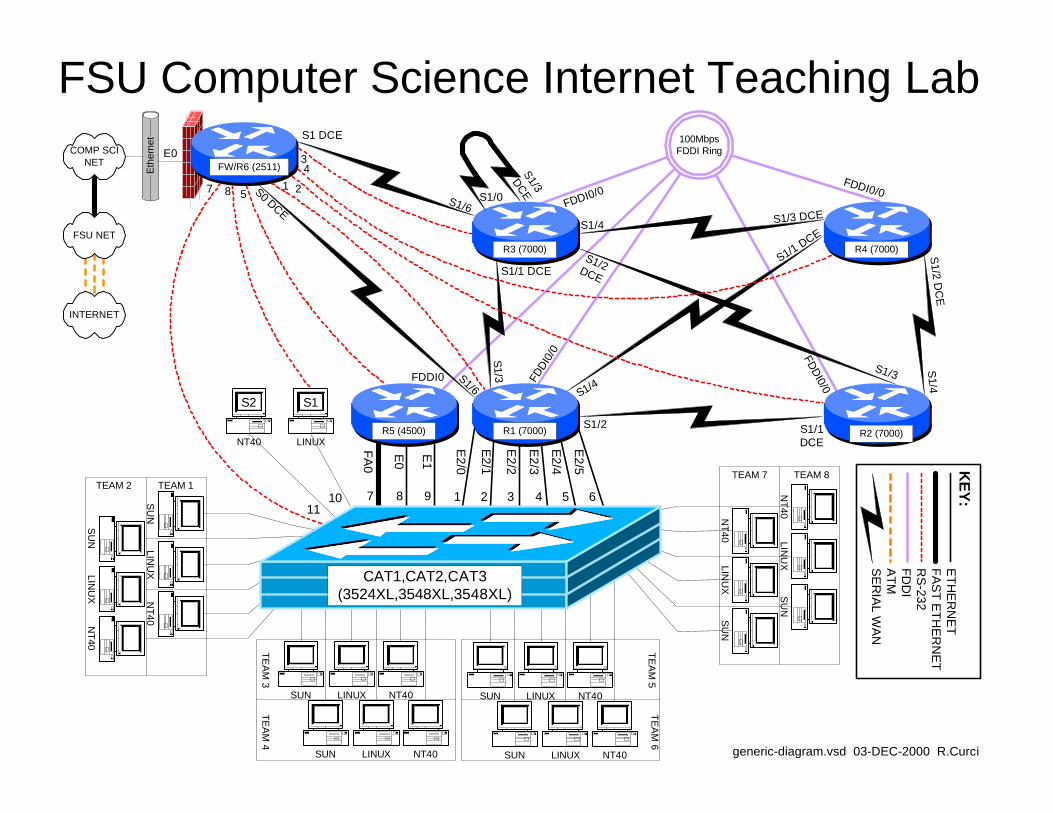
OVERVIEW In this lab, we will explore some of the basic information on how to configure a Cisco router. In particular, we will see how to access the FSU Computer Science Internet Teaching Lab routers through the Cisco 2511 firewall router, also known as R6. From that router, we will use a feature called “inverse telnet” to access other lab routers through external RS-232 cables. We will also explore some of the router modes including user mode, enable mode, global configuration mode, and sub configuration mode. For additional information you can access the Cisco IOS manuals online at http://www.cisco.com. (From the Cisco home page, choose Technical DocumentsàDocumentation Home PageàCisco IOS Software ConfigurationàCisco IOS Release 11.1àCisco IOS Configuration Guides and Command References). BACKGROUND The ITL lab consists of six Cisco routers labeled R1, R2, R3, R4, R5, and R6; three Cisco catalyst 3500XL series ethernet switches, and several PCs. Cisco routers run an operating system called Cisco IOS or Cisco Internetwork Operating System. Inside the

F:\basic\basic.doc Page 2 12/12/00
lab network, devices are numbered using IP private address space documented in the RFC1918 standard. Usually, the lab devices are numbered with the block of class C IP networks from 192.168.1.0/24 through 192.168.254.0/24. (If you are unfamiliar with the “/24” notation, it simply indicates the length of the subnet mask. For example, “/24” indicates a network mask of 255.255.255.0.) Routers R1, R2, R3, R4, and R5 are programmed by students to implement a series of lab exercises to learn about networking. Router R6 also called the “firewall” provides security and connects the lab network to the Computer Science departmental network and Internet. Only limited access is granted to students on this router to prevent changes that might compromise the integrity of the firewall. The firewall uses access lists to selectively block traffic on its ethernet interface. In particular, TELNET access is only permitted when originating from the FSU Computer Science departmental server XI.CS.FSU.EDU. Since the private IP address space is unknown on the Internet backbone, even without these access lists, the lab devices would be unreachable from the Internet. The firewall also performs another important function called “network address translation” or NAT. NAT is configured such that IP packets originating from the lab network will be translated where the source IP address of the packet is replaced by the R6 ethernet address so that it will be globally routable. When the destination server responds, R6 performs the translation in reverse. When enabled, this will allow PCs inside the lab network to access devices outside the lab when communication is initiated from inside the lab only. This will allow you to do things like download files with a web browser on the lab PCs from outside servers. For more background information, see the paper entitled “FSU Computer Science Internet Teaching Lab” which can be found at http://www.cs.fsu.edu/~curci/itl. PART1 – Log into the Cisco 2511: The Cisco 2511 firewall access router labeled R6 can be accessed in any of 3 ways:
1. Dumb Terminal or Terminal Emulator configured for 9600 baud and DEC VT100 emulation connected the router’s RS-232 console port.
2. TELNET to ethernet interface E0 from XI.CS.FSU.EDU. 3. TELNET to any router R6 interface from inside the lab network. (Only works
when the lab routers are configured to provide connectivity.)
We will use the second method. TELNET from XI.CS.FSU.EDU to the R6 interface E0 will allow you to log into router R6. You can TELNET either using the DNS name ITL1.CS.FSU.EDU or the IP address 128.186.121.88. Access lists on interface E0 will allow access only from XI.CS.FSU.EDU, so you will not be able to TELNET in from any other system outside the lab network. When you are connected, the router prompts you for the user mode password that should have been given to you by your instructor. You will also want to enter the command “enable 2” to increase your security level which will enable some commands otherwise not allowed in the user mode.

F:\basic\basic.doc Page 3 12/12/00
xi% telnet itl1 Trying 128.186.121.88... Connected to itl1. Escape character is '^]'. User Access Verification Password: xxxxxx fw/r6>enable 2 Password: xxxxxx fw/r6#
Note that the boldface type above indicates the part that you must type, although you should substitute the password for the “xxxxxx”.
Note on enable levels: Cisco routers have 16 privilege levels called “enable levels” numbered 0 through 15. Level 0 has the least privilege and cannot make any changes and is also called “user mode”. Level 15 is the most privileged and can make any changes and is often simply called “enable mode”. Intermediate levels are used to provide access between the two extremes. For example, in user mode you cannot list the startup configuration or change the configuration. However, you can set up an intermediate level that allows viewing the startup configuration but does not allow changing the configuration. That is what we have done on the firewall/R6 router with enable level 2. This prevents you from making changes to R6 but allows you to at least view the configuration to see what is going on. The command “enable X” prompts for a password and if accepted, changes to enable level X. If X is omitted, 15 is assumed. On the routers you will program, R1 through R5, we will only use enable levels 0 and 15 and refer to them as “user mode” and “enable mode”. Note that the command prompt changes between these two modes-- “user mode” has the “>” symbol while enable mode has the “#” symbol.
The RS-232 console ports on routers R1 through R5 connect to ports Line1 through Line5 on the 2511 respectively. You can connect to any of these routers across the RS-232 link by typing their name unless there is someone else already using the line. This feature is called “inverse telnet”. You can see if anyone else is logged into the firewall with “show user”. You can see any existing sessions you have with “show session”. Once connected to one of these lines, any characters you type are sent across the RS-232 link to the corresponding router and output from the router is displayed on your screen. The only exception is the special escape sequence that brings you back to router R6 – SHIFT-CONTROL-6-x. On your keyboard, press and hold the SHIFT key, press and hold the CONTROL key, then press the “6” key. Release all keys, then press “x”. You should now be back on router R6. The command “show session” will show you which sessions you have active. You can go back to your previous session by simply hitting return, or entering the integer session number displayed with the “show session” command. The command “clear line X” where X is the integer line number is sometimes necessary to clear an inactive session from an idle user. Here is a capture to demonstrate:

F:\basic\basic.doc Page 4 12/12/00
fw/r6#show user Line User Host(s) Idle Location 0 con 0 r1 2w4d * 18 vty 0 idle 00:00:00 128.186.121.41 fw/r6#show session % No connections open fw/r6#r1 Trying r1 (128.186.121.88, 2001)... Open r1# ß (RETURN and SHIFT-CONTROL-6-x typed here) fw/r6#r2 Trying r2 (128.186.121.88, 2002)... Open r2# ß (RETURN and SHIFT-CONTROL-6-x typed here) fw/r6#r3 Trying r3 (128.186.121.88, 2003)... Open r3> ß (RETURN and SHIFT-CONTROL-6-x typed here) fw/r6#show session Conn Host Address Byte Idle Conn Name 1 r1 128.186.121.88 0 0 r1 2 r2 128.186.121.88 0 0 r2 * 3 r3 128.186.121.88 0 0 r3 fw/r6#clear line 3 [confirm]y [OK] fw/r6#logout (You have open connections) [confirm] y Closing: r1 ! Closing: r2 ! Closing: r3 ! Connection closed by foreign host. xi%
Since only one person can use an RS-232 line at a time, if your network is already functional, it may be better to use TELNET from R6 to any of the other lab routers or PCs. By default, Cisco routers allow a maximum of 5 concurrent inbound TELNET sessions.
fw/r6#telnet 192.168.55.5 Trying 192.168.55.5 ... Open
User Access Verification Password: xxxxxx r5>enable Password: xxxxxx r5#logout
Once logged into your team router go to enable mode. Use the command “show version” to see your router’s IOS version number and operating system image filename. A baseline router configuration file should be located on your router’s flash memory device on a file named “base-rX.cfg” where X is the integer ID corresponding to your router. You can also find a listing of the baseline configuration at the end of this document. Get a directory on your flash filesystem with the command “dir flash:” and verify that the baseline configuration file is present. View this file with “show file flash:base-rX.cfg” If everything looks right, copy the baseline configuration file to your router’s startup

F:\basic\basic.doc Page 5 12/12/00
configuration with “copy flash:base-rX.cfg startup-config” and reboot with the new configuration using the “reload” command. Follow these steps carefully. After the last step, your router will take about 3 minutes to reboot. The following is an example of these steps on router R3 with some of the unimportant messages removed:
xi% telnet itl1.cs.fsu.edu Trying 128.186.121.88... Connected to itl1. User Access Verification Password: xxxxx fw/r6>en 2 Password: xxxxx fw/r6#r3 Trying r3 (128.186.121.88, 2003)... Open r3#enable r3#show version Cisco Internetwork Operating System Software IOS (tm) GS Software (GS7-J-M), Version 11.1(24), RELEASE SOFTWARE (fc1) r3 uptime is 2 days, 2 hours, 47 minutes System restarted by power-on System image file is "gs7-j-mz.111-24.bin", booted via flash cisco RP1 (68040) processor (revision A0) with 65536K bytes of memory. ... r3#dir flash: -#- -length- -----date/time------ name 1 4025994 --- -- ---- --:--:-- gs7-j-mz.111-24.bin 2 1289 --- -- ---- --:--:-- base-r3.cfg 165776 bytes available (4028528 bytes used) r3#show file flash:base-r3.cfg version 11.1 service udp-small-servers service tcp-small-servers ! hostname r3 ... r3#copy flash:base-r3.cfg startup-config Warning: distilled config is not generated [OK] r3#reload Proceed with reload? [confirm]y %SYS-5-RELOAD: Reload requested System Bootstrap, Version 5.0(5), RELEASE SOFTWARE RP1 processor with 65536 Kbytes of main memory Reading gs7-j-mz.111-24.bin from flash memory ... Press RETURN to get started! r3> r3>enable Password: xxxxx r3#

F:\basic\basic.doc Page 6 12/12/00
PART2 – IOS MODES: The Cisco IOS software can operate in four modes:
1. User Mode 2. Enable Mode 3. Global Configure Mode 4. Sub Configure Mode
ENABLEMODE
LOGGEDOFF
USERMODE
SUBCONFIGMODE
GLOBALCONFIGMODE
LOGOFFor
EXIT
LOGIN
ENABLEor
ENABLE 15
DISABLEor
ENABLE 0
INTERFACE orPROCESS toCONFIGURE
GLOBALCONFIG
COMMAND
CONFIG TERM
EXITor
ENDor
CONTROL-Z
LOGOFFor
EXIT
INTERFACE orPROCESS toCONFIGURE
The diagram above shows you how to switch between router modes. The following example shows logging into a router (user mode), using the “enable” command to go to enable mode, and using the “configure terminal” command. I then enter a simple configuration to assign an IP address on two interfaces and enable the RIP routing protocol. Note how the command prompt changes as we change between modes. Whitespace is ignored, so I have added whitespace in front of the sub config mode commands for clarity. Note also that a command prefixed with the word “no” negates the meaning of the command such as “shutdown” and “no shutdown”.

F:\basic\basic.doc Page 7 12/12/00
Configuration to be entered: ip classless interface ethernet2/0 ip address 192.168.10.1 255.255.255.0 no shutdown interface ethernet 2/1 ip address 192.168.20.1 255.255.255.0 router rip network 192.168.10.0 network 192.168.20.0 no ip domain-lookup
Here is the captured session:
fw/r6#telnet 192.168.11.1 Trying 192.168.11.1 ... Open User Access Verification Password: xxxxxx r1>enable Password: xxxxxx r1#configure terminal Enter configuration commands, one per line. End with CNTL/Z. r1(config)#ip classless r1(config)#interface ethernet2/0 r1(config-if)#ip address 192.168.10.1 255.255.255.0 r1(config-if)#no shutdown r1(config-if)#interface ethernet2/1 r1(config-if)#ip address 192.168.20.1 255.255.255.0 r1(config-if)#no shutdown r1(config-if)#router rip r1(config-router)#network 192.168.10.0 r1(config-router)#network 192.168.20.0 r1(config-router)#exit r1(config)#no ip domain-lookup r1(config)#exit r1#logout
When entering commands, you need only enter enough letters for it to be unique. For example, you can use “config t” in place of “configuration terminal”. You can also type the question mark “?” at any point to see your options. If your terminal emulates a DEC VT100, you can also use the UP, DOWN, LEFT, and RIGHT arrow keys to recall previous commands and edit them. Here is a session capture that makes the same router configuration as shown above but demonstrates using abbreviated commands and the built-in “?” HELP facility.

F:\basic\basic.doc Page 8 12/12/00
fw/r6#telnet 192.168.11.1 Trying 192.168.11.1 ... Open User Access Verification Password: xxxxxx r1>en Password: xxxxxx r1#conf t Enter configuration commands, one per line. End with CNTL/Z. r1(config)#ip clas? classless r1(config)#ip classless r1(config)#int e2/0 r1(config-if)#ip add 192.168.10.1 255.255.255.0 r1(config-if)#no shut r1(config-if)#int e2/1 r1(config-if)#ip add 192.168.20.1 255.255.255.0 r1(config-if)#no shut r1(config-if)#router rip r1(config-router)#net 192.168.10.0 r1(config-router)#net 192.168.20.0 r1(config-router)#exit r1(config)#no ip d? default-gateway default-network dhcp-server domain-list domain-lookup domain-name dvmrp r1(config)#no ip domain? domain-list domain-lookup domain-name r1(config)#no ip domain-lookup r1(config)#^Z r1#lo
Log into your router and modify the configuration to display a login message that says “Team X Router” replacing X with your team number using the “banner login” command. Also change your router’s command prompt from “rX” to “teamX” using the “hostname” command. Use the “show interface loopback0” and “show running-config” to view the configuration on your loopback0 interface. Delete your router’s loopback0 interface with “no interface loopback0” Verify it is gone with “show running-config”. Then put the interface back in with “interface loopback0” Make sure you remember to assign the interface an IP address and make sure it NOT shutdown. Since we have not saved any configuration changes in this part, if you get stuck, you can always use the “reload” command to reboot which will undo any changes you have made. Just remember that if you are prompted to save change, you should answer “NO”. PART3 – Saving and Viewing Configurations: Cisco routers have two configurations, the startup configuration, and the running configuration. Normally, when a router is booted, it reads in the startup configuration which is stored in flash memory. Once the router is running, the current configuration in RAM is called the running configuration. If no changes are made after booting, both the startup and running configurations will be the same. You can make changes interactively
F:\basic\basic.doc Page 9 12/12/00
to the running configuration. You can also commit the changes to the startup configuration in flash or reboot which will cause any changes you have made to be lost. Here are the relevant commands:
- show startup-config List the startup configuration in flash to the screen.
- show running-config List the running configuration currently executing in RAM to the screen.
- copy running-config startup-config Copy the currently running configuration to the startup configuration in flash to commit any changes you have made. The committed changes will persist even after rebooting the router.
- terminal length 24 Set the router to pause every 24 lines when displaying messages larger than 24 lines.
- terminal length 0 Set the router to not pause when display messages, no matter how long they are even if they scroll off the screen. This is sometimes handy when using a terminal emulator to capture a command with lots of output.
- reload Reboot the router.
- write erase Completely erase the startup configuration. Use with care!
- write An old deprecated command that is a synonym for “copy running-config startup-config”
- write terminal An old deprecated command that is a synonym for “show running-config”

F:\basic\basic.doc Page 10 12/12/00
Your assignment is to capture your router’s running configuration to a text file, erase the startup config and reboot so your router will have no configuration, then get the your text file config back into the router and commit the changes. Afterwards, verify that your router will reboot with the appropriate configuration. Use the following steps to guide you through the process.
1. Log into your router and go to enable mode. 2. Configure your terminal session to inhibit paging. 3. Configure your terminal emulator to capture text. 4. Display the running configuration to your screen while simultaneously
capturing it to a text file. 5. Stop capturing text and edit the captured text file with a text editor, removing
any extraneous text. 6. Completely erase your router’s startup configuration with “erase startup-
config” 7. Reboot your router with “reload” 8. After rebooting, you may see an error message indicating that the startup
configuration is missing and get prompted by the auto configuration dialog. You should be able to simply press control-C to cancel the dialog.
9. Log into your router, go to enable mode, and list the running configuration to your screen. Compared to your captured text file in step 5 and explain which part of the configuration is still there and which part is missing.
10. Go to global configuration mode and use copy and paste to put the configuration back into your router.
11. List the running configuration and compared to your saved configuration from step 5. How do they differ? Fix any differences so the running configuration is identical to your saved configuration from step 5.
12. Save your changes by copying the running configuration to the startup configuration.
13. Reboot your router and verify it reboots with the correct configuration. 14. Log into your router and go to enable mode. Configure your session to not
page every 24 lines. Set your terminal emulator program to capture text. Display the running configuration to your screen while simultaneously capturing to a text file. Get the text file into some text editor and clean up any extraneous text.

F:\basic\basic.doc Page 11 12/12/00
PART4 – Miscellaneous Commands: Read up on the following commands and try them out on your router. Provide a brief explanation of what each does.
1. telnet 2. ping 3. traceroute 4. show version 5. show clock 6. show diagbus 7. show interface 8. show ip interface brief 9. show ip routing 10. show ip protocol

F:\basic\basic.doc Page 12 12/12/00
BASELINE ROUTER CONFIGURATION: For completeness, here is a listing of the baseline router configuration mentioned in part 1 for routers R1, R2, R3, R4 and R5. The section labeled “COMMON:” is needed on all routers. The sections labeled “R1:”, “R2”, etc, are the router specific sections. These configurations should already be present on each router’s flash memory on file “base-rX.cfg” where X is the integer identifier of the router. COMMON: service udp-small-servers service tcp-small-servers enable password cisco no ip domain-lookup no ip classless logging buffered snmp-server community public RO line con 0 exec-timeout 0 0 line aux 0 line vty 0 4 password cisco login R1: hostname r1 interface Loopback0 ip address 192.168.11.1 255.255.255.0 no shutdown interface Fddi0/0 ip address 192.168.1.1 255.255.255.0 no shutdown interface Serial1/2 description Link to R2 S1/1 ip address 192.168.12.1 255.255.255.0 bandwidth 2000 no shutdown interface Serial1/3 description Link to R3 S1/1 ip address 192.168.13.1 255.255.255.0 bandwidth 2000 no shutdown interface Serial1/4 description Link to R4 S1/1 ip address 192.168.14.1 255.255.255.0 bandwidth 2000 no shutdown interface Serial1/6 description Link to R6 S0 ip address 192.168.16.1 255.255.255.0 bandwidth 2000 no shutdown interface E2/0 description Vlan 10 to cat1 FA0/1 ip address 192.168.10.1 255.255.255.0 no shutdown interface E2/1 description Vlan 20 to cat1 FA0/2 ip address 192.168.20.1 255.255.255.0 no shutdown interface E2/2 description Vlan 30 to cat1 FA0/3 ip address 192.168.30.1 255.255.255.0 no shutdown interface E2/3 description Vlan 40 to cat1 FA0/4 ip address 192.168.40.1 255.255.255.0
no shutdown interface E2/4 description Vlan 50 to cat1 FA0/5 ip address 192.168.50.1 255.255.255.0 no shutdown interface E2/5 description Vlan 60 to cat1 FA0/6 ip address 192.168.60.1 255.255.255.0 no shutdown router rip network 192.168.11.0 network 192.168.12.0 network 192.168.13.0 network 192.168.14.0 network 192.168.16.0 network 192.168.1.0 network 192.168.10.0 network 192.168.20.0 network 192.168.30.0 network 192.168.40.0 network 192.168.50.0 network 192.168.60.0 R2: hostname r2 interface Loopback0 ip address 192.168.22.2 255.255.255.0 no shutdown interface Fddi0/0 ip address 192.168.1.2 255.255.255.0 no shutdown interface Serial1/1 description Link to R1 S1/2 ip address 192.168.12.2 255.255.255.0 bandwidth 2000 clockrate 2000000 no shutdown interface Serial1/3 description Link to R3 S1/2 ip address 192.168.23.2 255.255.255.0 bandwidth 2000 no shutdown interface Serial1/4 description Link to R4 S1/2 ip address 192.168.24.2 255.255.255.0 bandwidth 2000 no shutdown router rip network 192.168.12.0 network 192.168.22.0 network 192.168.23.0 network 192.168.24.0 network 192.168.1.0 R3: hostname r3 interface Loopback0

F:\basic\basic.doc Page 13 12/12/00
ip address 192.168.33.3 255.255.255.0 no shutdown interface Fddi0/0 ip address 192.168.1.3 255.255.255.0 no shutdown interface Serial1/0 description Link to self no ip address bandwidth 2000 no shutdown interface Serial1/1 description Link to R1 S1/3 ip address 192.168.13.3 255.255.255.0 bandwidth 2000 clockrate 2000000 no shutdown interface Serial1/2 description Link to R2 S1/3 ip address 192.168.23.3 255.255.255.0 bandwidth 2000 clockrate 2000000 no shutdown interface Serial1/3 description Link to self no ip address bandwidth 2000 clockrate 2000000 no shutdown interface Serial1/4 description Link to R4 S1/3 ip address 192.168.34.3 255.255.255.0 bandwidth 2000 no shutdown interface Serial1/6 description Link to R6 S1 ip address 192.168.36.3 255.255.255.0 bandwidth 2000 no shutdown router rip network 192.168.33.0 network 192.168.13.0 network 192.168.23.0 network 192.168.34.0 network 192.168.36.0 network 192.168.1.0 R4: hostname r4 interface Loopback0 ip address 192.168.44.4 255.255.255.0 no shutdown interface Fddi0/0 description Link to R5 FDDI0 ip address 192.168.1.4 255.255.255.0 no shutdown interface Serial1/1
description Link to R1 S1/4 ip address 192.168.14.4 255.255.255.0 bandwidth 2000 clockrate 2000000 no shutdown interface Serial1/2 description Link to R2 S1/4 ip address 192.168.24.4 255.255.255.0 bandwidth 2000 clockrate 2000000 no shutdown interface Serial1/3 description Link to R3 S1/4 ip address 192.168.34.4 255.255.255.0 bandwidth 2000 clockrate 2000000 no shutdown router rip network 192.168.44.0 network 192.168.14.0 network 192.168.24.0 network 192.168.34.0 network 192.168.1.0 R5: hostname r5 interface loopback0 ip address 192.168.55.5 255.255.255.0 no shutdown interface FastEthernet0 description Vlan70 to cat1 FA0/7 ip address 192.168.70.1 255.255.255.0 media-type 100BaseX no shutdown interface Ethernet0 description Vlan80 to cat1 FA0/8 ip address 192.168.80.1 255.255.255.0 media-type 10BaseT no shutdown interface Ethernet1 description Vlan90 to cat1 FA0/9 ip address 192.168.90.1 255.255.255.0 media-type 10BaseT no shutdown interface Fddi0 description Link to R4 FDDI0/0 ip address 192.168.1.5 255.255.255.0 no keepalive no shutdown router rip network 192.168.55.0 network 192.168.70.0 network 192.168.80.0 network 192.168.90.0 network 192.168.1.0

SU
NLIN
UX
NT
40
SU
NLIN
UX
NT
40
TEAM 1TEAM 2
SUN LINUX NT40
SUN LINUX NT40
SUN LINUX NT40
SUN LINUX NT40
TE
AM
3T
EA
M 4
TE
AM
5T
EA
M 6
Eth
erne
tCOMP SCI
NET
100MbpsFDDI Ring
R5 (4500) R1 (7000)
R4 (7000)
generic-diagram.vsd 03-DEC-2000 R.Curci
SU
NLIN
UX
NT
40
SU
NLIN
UX
NT
40
TEAM 7 TEAM 8
FA
0
E0
E1
E2/0
E2/1
E2/2
E2/3
E2/4
E2/5
LINUXNT40
S1S2
R3 (7000)
R2 (7000)
FW/R6 (2511)
CAT1,CAT2,CAT3(3524XL,3548XL,3548XL)
FSU NET
INTERNET
FSU Computer Science Internet Teaching LabE
TH
ER
NE
TF
AS
T E
TH
ER
NE
TR
S-232
FD
DI
AT
MS
ER
IAL W
AN
KE
Y:
S1/3DC
ES1/0S1/6 FDDI0/0
S1/4
S1/2DCES1/1 DCE
FDDI0 FDD
I0/0 FD
DI0/0
S1/1DCE
S1/3
S1/4
S1/2 D
CE
S1/3 DCE
S1/1 DCE
S1/3
S1/4
S1/2
S1/6
S1 DCE
S0 DCE
27 8 51
34
E0
7 8 9 1 2 3 4 5 61011
FDDI0/0

ENABLEMODE
basic-fsm.vsd 17-Oct-2000 R.Curci
LOGGEDOFF
USERMODE
SUBCONFIGMODE
GLOBALCONFIGMODE
CISCO ROUTER BASICSCISCO IOS SOFTWARE MODES
LOGOFFor
EXIT
LOGIN
ENABLEor
ENABLE 15
DISABLEor
ENABLE 0
INTERFACE orPROCESS toCONFIGURE
GLOBALCONFIG
COMMAND
CONFIG TERM
EXITor
ENDor
CONTROL-Z
LOGOFFor
EXIT
INTERFACE orPROCESS toCONFIGURE

F:\debug\debug.doc Page 1 12/12/00
INTERNET TEACHING LAB: CISCO ROUTER DEBUGGING
SU
NLIN
UX
NT40
SU
NLIN
UX
NT40
TEAM 1TEAM 2
SUN LINUX NT40
SUN LINUX NT40
SUN LINUX NT40
SUN LINUX NT40
TEA
M 3
TEA
M 4
TEA
M 5
TEA
M 6
Eth
erne
t
COMP SCINET
100MbpsFDDI Ring
R5 (4500) R1 (7000)
R4 (7000)
generic-diagram.vsd 03-DEC-2000 R.Curci
SU
NLIN
UX
NT40
SU
NLIN
UX
NT40
TEAM 7 TEAM 8
FA0
E0
E1
E2/0
E2/1
E2/2
E2/3
E2/4
E2/5
LINUXNT40
S1S2
R3 (7000)
R2 (7000)
FW/R6 (2511)
CAT1,CAT2,CAT3(3524XL,3548XL,3548XL)
FSU NET
INTERNET
FSU Computer Science Internet Teaching LabE
THE
RN
ET
FAS
T ETH
ER
NE
TR
S-232
FDD
IA
TMS
ER
IAL W
AN
KE
Y:
S1/3DCE
S1/0S1/6 FDDI0/0
S1/4
S1/2DCES1/1 DCE
FDDI0 FDDI
0/0 FDDI0/0
S1/1DCE
S1/3 S1/4
S1/2 D
CE
S1/3 DCE
S1/1 DCE
S1/3
S1/4
S1/2
S1/6
S1 DCE
S0 DCE
27 8 51
34
E0
7 8 9 1 2 3 4 5 61011
FDDI0/0
OVERVIEW Debug mode is a feature of the Cisco IOS software to locate router configuration errors and software bugs. Log messages are similar to debug messages and are generally alerts to problems. You can think of log messages as debug messages that cannot be turned off. Problems are diagnosed by reviewing descriptive messages generated by the router. There are hundreds of different debug options that can be individually turned on and off depending on what part of the system is under examination. It is possible to turn on all debug modes simultaneously, however, this is rarely appropriate as the volume of information would be too voluminous. Debug mode should generally not be used on a production network as it is easy to generate hundreds of error messages per second and cause a router to crash and reboot. We will also explore some of the “show” commands used for debugging problems. This lab assignment assumes you have the base router configuration from the “Cisco Router Basics” loaded with the RIP routing protocol. The following is a sample of some debug and log messages. I have removed the timestamps to fit the messages on the page.

F:\debug\debug.doc Page 2 12/12/00
(Sample of debug and log messages) r1#term monitor r1#debug all This may severely impact network performance. Continue? [confirm] y All possible debugging has been turned on %LINEPROTO-5-UPDOWN: Line protocol on Interface Serial1/2, changed state to down %LINK-3-UPDOWN: Interface Serial1/2, changed state to up %SYS-5-CONFIG_I: Configured from memory by console %SYS-5-RESTART: System restarted -- Cisco Internetwork Operating System Software IOS (tm) GS Software (GS7-J-M), Version 11.1(24), RELEASE SOFTWARE (fc1) %ENVM-2-SUPPLY: Upper Power Supply is Non-Operational %LINK-4-FDDISTAT: Interface Fddi0/0, FDDI state c_wrap_b detected? IP: s=192.168.16.6 (Serial1/6), d=224.0.0.10, len 64, dispose 31 SMT I: Fddi0/0, FC=SMT, DA=0000.309c.fb2d, SA=0 000.309c.9e3f, IP: s=192.168.16.6 (Serial1/6), d=255.255.255.255, len 176, rcvd 2 UDP: rcvd src=192.168.16.6(520), dst=255.255.255.255(520), length=152 RIP: received v1 update from 192.168.16.6 on Serial1/6 0.0.0.0 in 5 hops 192.168.13.0 in 16 hops (inaccessible) 192.168.66.0 in 1 hops Serial1/2: HDLC myseq 8, mineseen 8*, yourseen 11, line up RIP: sending v1 update to 255.255.255.255 via Serial1/2 (192.168.12.1) default, metric 6 network 192.168.66.0, metric 2 RIP: Update contains 21 routes RIP: Update queued RIP: Update sent via Serial1/2 CDP-PA: Packet received from cat1 on interface Ethernet2/0 r1#undebug all PART 1 – SHOW COMMANDS: Although not technically debug commands, there are several “show” commands that are helpful with debugging and worth mentioning. Read about the following “show” commands using either the hardcopy Cisco manuals or online manuals at www.cisco.com and try them out on your router. Include a brief description what each of these commands does for your assignment:
1. show version 2. show controller [cbus | serial] 3. show cdp neighbors [detail] 4. show interface 5. show ip interface [brief] 6. show ip protocol 7. show memory 8. show processes cpu 9. show diagbus (7000 only) 10. show tech-support

F:\debug\debug.doc Page 3 12/12/00
Using information gathered on your router using the above “show” commands, answer the following questions:
1. What IOS software is your router running? What is the filename of the IOS image? How much RAM? FLASH? What is the value of the configuration register? What model CPU does your router have?
2. For each of your router’s serial WAN interfaces, what kind of cable is attached (DTE, DCE, or none)?
3. Which adjacent routers are sending CDP messages to your router? What IOS software version is running on the adjacent CDP routers?
4. What is the MAC address of your router’s FDDI interface? 5. For each of your router’s active interfaces, is IP Split-Horizon enabled? 6. For the RIP protocol running on your router, what are the values of the
RIP protocol update, invalid, holddown, and flush timers? 7. How much TOTAL, USED, and FREE RAM is in your router? 8. What is the average CPU utilization for the last 5 minutes? 9. On your 7000 router, what card is physically located in slot 0? What is its
hardware revision and serial number?
PART 2 – SET THE CLOCK: Debug messages are often examined on multiple router devices to study the sequence of events. It is often very useful to configure the debug messages to include a timestamp in order to correlate events in different log files. Setting the router clock is important to make the correlation possible. The current system clock can be displayed with the “show clock” command and set with the “clock set” command. Like UNIX, the Cisco router internally maintains the time as a long integer indicating the number of seconds that have elapsed since January 1st, 1970 GMT (Greenwich Mean Time). Sometimes GMT is called UTC (Universal Time Coordinated). By setting the appropriate time zone, number of hours offset from UTC, and daylight savings time information, the router can display the correct local time. Configure your router’s time zone and daylight savings time information. Configure so that your router will display the local time appropriately and adjust automatically between standard time and daylight savings time. Manually set your router’s clock. PART 3 – NETWORK TIME PROTOCOL: In the previous section, we saw how to manually set the router clock and timezone information. Sometimes it is helpful to automatically keep the clocks in sync or synchronize them more accurately than can be done manually. Cisco routers include software that implements the NTP (Network Time Protocol) version 3. NTP can typically maintain the clock accuracy within a few milliseconds. NTP devices maintain relationships with other NTP devices such as “master”, “client”, and “peer”. Each NTP device has a stratum number which indicates the clock’s accuracy and believability. We

F:\debug\debug.doc Page 4 12/12/00
will configure routers R1, R2, R3, R4, and R5 as NTP clients of router R6, a stratum 4 NTP server. Configure your router to be an NTP client of NTP server R6. Verify that your clock is synchronized using the “show ntp status”, “show ntp associations”, and “show ntp associations detail” commands. A full discussion of NTP is beyond the scope of this document, however, additional information can be found at http://www.eecis.udel.edu/~ntp/. PART 4 – TIMESTAMPS: Timestamps can be prepended to debug or log messages. A timestamp can be either an indication of the uptime (how much time has elapsed since the router was booted) or the current date and time. The date and time can be in UTC or the local timezone. Optionally, the timezone and/or the number of milliseconds can be included. Configure your router so that timestamps for both DEBUG and LOG messages will display the local time including the timezone and millisecond information. Verify that it is working.
PART 5 -- OUTPUT OPTIONS: Debug and log messages generated have three different modes of output: (1) console screen, (2) internal circular buffer, or (3) syslog server.
1. Console Screen Using the console screen is probably the simplest way to view messages as they are generated. The command “term monitor” enables the display of messages while “term no monitor” inhibits the messages.
2. Internal Circular Buffer Part of a router’s RAM memory can be allocated to be a circular logging buffer using the configuration command “logging buffer XXXX” where XXXX indicates the size of the buffer. The contents of the buffer can be displayed with the “show logging” command.
3. Syslog Server
A syslog server is a TCP/IP service that accepts log messages and appends them to log files. Both UNIX and NT server systems can be configured as syslog servers. Syslog servers can be used to centralize the collection of messages from many systems to ease system administration. Syslog uses the concepts of facility and severity level. Facility classifies the messages by subsystem to allow the server to append the proper log file. The severity level provides an indication of the importance of an error message where the system manager can set a severity level threshold on both the router and syslog server. On the router, messages with lower priority than the threshold are never sent to the syslog server. A threshold set on the syslog server indicates the minimal importance necessary for a message

F:\debug\debug.doc Page 5 12/12/00
to be logged to a file which is otherwise discarded. By default, Cisco routers use the syslog facility “local7” and severity “informational”, but these parameters are adjustable. Severity “informational” will send more messages except those with severity “debug”. In this part, we will use severity level “debug” so that all messages are important enough to be forwarded from the router to the syslog server and all will be logged by the syslog server.
Configure your router so that debug messages will be logged to three different locations (1) to the console screen, (2) to the internal circular buffer, and (3) to your Linux system using facility “local7” and “severity debug”. Your Linux server should append the messages to file /var/log/cisco.log. We will work on generating messages in the next part. PART 5 – DEBUG MODE: The command “debug” is used to enable the various debug modes. You can see the options with “debug ?”. Each debug mode can be individually enabled or disabled using “debug xxxxx” to turn on a mode or “no debug xxxxx” to turn one off. The command “show debug” displays which debug modes are currently enabled. You can use the command “debug all” to turn on all debug modes, but it is generally not useful as it can generate hundreds of messages per second. You can turn off all debug modes with the command “no debug all” or “undebug all”. Turn on icmp debugging “debug ip icmp” and ping one of your router’s interfaces. Turn off debugging. Review the messages on your console screen, in your circular buffer, and on your syslog server’s /var/log/cisco.log file. Are the entries identical? If not, explain what is different
SU
NLIN
UX
NT
40
SU
NLIN
UX
NT
40
TEAM 1TEAM 2
SUN LINUX NT40
SUN LINUX NT40
SUN LINUX NT40
SUN LINUX NT40
TE
AM
3T
EA
M 4
TE
AM
5T
EA
M 6
Eth
erne
tCOMP SCI
NET
100MbpsFDDI Ring
R5 (4500) R1 (7000)
R4 (7000)
generic-diagram.vsd 03-DEC-2000 R.Curci
SU
NLIN
UX
NT
40
SU
NLIN
UX
NT
40
TEAM 7 TEAM 8
FA
0
E0
E1
E2/0
E2/1
E2/2
E2/3
E2/4
E2/5
LINUXNT40
S1S2
R3 (7000)
R2 (7000)
FW/R6 (2511)
CAT1,CAT2,CAT3(3524XL,3548XL,3548XL)
FSU NET
INTERNET
FSU Computer Science Internet Teaching LabE
TH
ER
NE
TF
AS
T E
TH
ER
NE
TR
S-232
FD
DI
AT
MS
ER
IAL W
AN
KE
Y:
S1/3DC
ES1/0S1/6 FDDI0/0
S1/4
S1/2DCES1/1 DCE
FDDI0 FDD
I0/0 FD
DI0/0
S1/1DCE
S1/3
S1/4
S1/2 D
CE
S1/3 DCE
S1/1 DCE
S1/3
S1/4
S1/2
S1/6
S1 DCE
S0 DCE
27 8 51
34
E0
7 8 9 1 2 3 4 5 61011
FDDI0/0

F:\top\top.doc Page 1 12/12/00
INTERNET TEACHING LAB: TOPOLOGY DISCOVERY
128.
186.
121.
0/24
VLAN90VLAN80VLAN70VLAN50 VLAN60VLAN40VLAN30VLAN20VLAN10
S1192.168.10.2/24
top-detail.vsd 30-Nov-2000 R.Curci
FW/R6 (2511)
COMP SCINETWORK
10 20 30 40 50 60 70 80 90
LINUX
NT
SUN
LINUX
NT
SUN
LINUX
NT
SUN
LINUX
NT
SUN
LINUX
NT
SUN
LINUX
NT
SUN
LINUX
NT
SUN
LINUX
NT
SUN
Addresses are RFC1918private address space,192.168.XXX.0/24 whereXXX is the networkidentifier indicated onthis diagram. RIP v1 isused internally.
LINUX
NT
SUN
?
?
?
?
??
?
CLOUD VIEW
R1 (7000)
R2 (7000)
R3 (7000)
R4 (7000)
R5 (4500)
S2192.168.10.3/24
TOPOLOGY DISCOVERY
Overview Each team has a set of computers on its own ethernet VLAN connected to a working lab network of six Cisco routers. Your task is to configure the TCP/IP protocol on your computers and verify you can communicate between your PCs, with other team PCs, the routers, and systems outside the lab on the Internet. Once you have basic connectivity, your job is to download and use network tools to discover the IP addressing scheme and network topology of the lab network. You will be given hints but no login access to the routers for this assignment. Your journal should detail how you discovered different aspects of the addressing scheme and topology and include a detailed network diagram showing the routers, connections between routers, bandwidth of the connections, and IP addresses for all router interfaces, including where the team VLANs attach to the lab network. Hints For this exercise inside the lab network, we will be using RFC1918 private address space for all router and computer interfaces. The only exceptions are a single real address on

F:\top\top.doc Page 2 12/12/00
router FW/R6 which is performing network address translation (NAT) to allow lab computers to access the Internet for downloading files, and a special UNIX server with two ethernet ports. The special UNIX server does not route, but you can TELNET in from outside the lab, then TELNET to your team computers, allowing indirect access. The six Cisco routers are running the IOS operating system and intentionally have many of the security features disabled to make your job easier. The routers connect to each other through different physical network media at different bandwidths. All layer 3 networks use a 24 bit network mask. Several router features that might normally be disabled have been turned on such as “service tcp-small-servers”, “ip directed-broadcast”, and “ip source-route”. SNMP is enabled on all routers with a read-only community string “public”. PART1 – GETTING STARTED: Address your team computers using the following table by replacing TEAM with your integer team number: LINUX 192.168.X.Y X= 10 * TEAM Y= X + 1 NT 192.168.X.Y X= 10 * TEAM Y= X + 2 SOLARIS 192.168.X.Y X= 10 * TEAM Y= X + 3 For example, team 5’s NT system should be addressed with 192.168.50.52/24. To test basic connectivity, verify you can PING(1) each of the other teams’ local gateway IP address. On each of your computers, install the RIP version 1 routing protocol. Under UNIX, you can use either GateD or RouteD in passive mode. Under NT 4.0, use “RIP for Internet Protocol”. Your computers should learn a list of routes including a special “default route” sometimes abbreviated “0.0.0.0”. Make sure you have removed any static default routes and are learning the default dynamically. Build a table of routes including the RIP metric. This metric indicates the number of router hops from your computer to each of the networks and will help in figuring out the topology. Hint: The UNIX utility ripquery(1) may be helpful. PART2 – FIND THE SIX ROUTERS: Given the network list from part 1, PING(1) the broadcast address for each network you found above. Normally, you will hear responses from the IP address of the router interface closest to your computer connected to the destination network. If you see more than one IP address in the responses, it is an indication that there are multiple routers on the broadcast network with different paths back to your computer.

F:\top\top.doc Page 3 12/12/00
Use the TRACEROUTE(1) utility to find some of the connections between the routers. (This utility is named TROUTE.EXE under NT). For each lab network, select an IP address and trace the route to it, making a note of the IP addresses of the routers in the path. Be sure to trace the route toward the Internet by tracing to a computer science server outside the lab. You should be able to find an IP address for each of the six routers. Note that routers generally have multiple interfaces each with its own IP address, so you may find multiple IP addresses that belong to the same router. Download install the NMAP(1) utility for UNIX. You can find it at www.insecure.org/nmap. Use this tool to scan the 192.168.0.0/16 address space to find all devices and attempt to guess their operating systems. Be careful not to scan outside the 192.168.0.0/16 lab network as most System Administrators treat scanning as an attack and will likely trigger many intrusion detection alarms. Under Florida Law, port scanning is treated as unauthorized intrusion. PART4 – Simple Network Management Protocol (SNMP) All of the lab routers will respond to SNMP version 1 queries. SNMP version 1 uses a simple password protection scheme called a “community”. Each router is programmed to be an SNMP “agent” and will respond to the read-only community string “public”. SNMP agents store data in a Management Information Base, or MIB. The MIB contains a lot of information including the router name, the uptime, software version, interface names, interface IP addresses, routing tables, etc. Many SNMP tools are available for Linux:
snmpbulkget snmpget snmpset snmptest snmpusm snmpbulkwalk snmpgetnext snmpstatus snmptranslate snmpwalk snmpdelta snmpnetstat snmptable snmptrap
For example, you can display individual MIB variables with SNMPGET(1): LINUX$ snmpget 192.168.10.1 public system.sysDescr.0 system.sysDescr.0 = Cisco Internetwork Operating System Software IOS (tm) GS Software (GS7-J-M), Version 11.1(24), RELEASE SOFTWARE (fc1) Copyright (c) 1986-1999 by cisco Systems, Inc. Compiled Mon 04-Jan-99 21:19 by richv LINUX$
For each of your routers, look up the following MIB variables: system.sysDescr.0 system.sysName.0 This will let you see the router names to eliminate any duplicates if you previously found more than one IP address for the same router. Using the system description, note the IOS software version of the router. You should now have enough information to draw a diagram of the six routers with the interface names, interface types (ethernet, fddi, point-to-point, loopback), how they connect to each other, and the IP addressing scheme.

F:\top\top.doc Page 4 12/12/00
PART5 – Bandwidth Measurement (IPERF/PCHAR): IPERF(1) is a tcp performance measurement tool. It is an updated version of the Test TCP program (TTCP) written by Terry Slattery in 1985 at the US Navy Ballistic Research Lab. You can find the latest version at http://dast.nlanr.net/Projects/Iperf/. You will find both UNIX source code that complies under Linux and SUNOS, and Microsoft Windows executable files (iperf.exe and iperf-threaded.exe). Normally, you start one copy of IPERF(1) in server mode, and the other in client mode specifying the server’s IP address. This utility in client mode will also work with an ordinary TCP/IP device supporting the trivial TCP DISCARD service on TCP port 9 which is enabled on all lab routers. Measure the performance from your computer to each router to help determine the bandwidth between links on your network. Note that if the packets traverse several links, the slowest link in the path will be the determining factor. PCHAR(1) is a utility similar to TRACEROUTE(1), but tries to determine the bandwidth between adjacent hops in the path. It is an updated version of PATHCHAR(1) written by Van Jacobson at Lawrence Berkeley Labs, namesake of the IP Van Jacobson header compression. You will need to either change permissions on PCHAR(1) to be SUID root or execute it while logged in as root. It can be found at http://www.employees.org/~bmah/Software/pchar/ Be patient with this program as it can take a long time to run using the default settings. PART6 – Windows NT Network Management / WhatsUp Gold: Download and install the utility “WhatsUp Gold” on your NT machine. You can download a 30-day evaluation copy from www.ipswitch.com. You will find both a self-installing Win95/98/NT/2000 executable and a users guide in Adobe Acrobat PDF format. If you don’t have Adobe Acrobat Reader already loaded, you can find it at www.adobe.com. As of this writing, the latest software is version 5. Test out the following tools and verify the results are consistent with your topology drawing:
- traceroute tool - snmp tool - scan tool - throughput tool
How does the SCAN tool compare to the UNIX NMAP utility? Run the throughput tool to test each router using both the ICMP and TCP/discard/port-9 modes. How do these measurements compare to each other and to tests you made earlier with the UNIX IPERF utility?

F:\top\top.doc Page 5 12/12/00
Use this software to create a live map of your network including the six routers and IP networks. Change the polling method to TCP/IP— SNMP since this provides more information than the default ICMP method. Edit the symbols on the map to abbreviate the router names such as “R1” and network names using the third octet of the IP network number. This will help give you more room to fit all the icons on the screen. Configure the system to poll the devices every 10 seconds (Make sure you are not polling any devices outside of the lab environment). If configured properly, you should be able to view the map where the icon color indicates the status (i.e. green=good) and you should also be able to right-click your mouse on the router icons to Telnet, Ping, Traceroute, etc., to the highlighted device. Configure the system such that if any of the routers go down on weekdays between 9am and 5pm, the system will send you an automatic e-mail message. Configure the system to implement a WWW server such that you can check the status of your network remotely with the use of a web browser. Hint: The “discover devices/intelligently scan network devices with SNMP seed router” function may save you time to initially build your map.

128.
186.
121.
0/24
VLAN90VLAN80VLAN70VLAN50 VLAN60VLAN40VLAN30VLAN20VLAN10
S1192.168.10.2/24
top-detail.vsd 30-Nov-2000 R.Curci
FW/R6 (2511)
COMP SCINETWORK
10 20 30 40 50 60 70 80 90
LINUX
NT
SUN
LINUX
NT
SUN
LINUX
NT
SUN
LINUX
NT
SUN
LINUX
NT
SUN
LINUX
NT
SUN
LINUX
NT
SUN
LINUX
NT
SUN
Addresses are RFC1918private address space,192.168.XXX.0/24 whereXXX is the networkidentifier indicated onthis diagram. RIP v1 isused internally.
LINUX
NT
SUN
?
?
?
?
??
?
CLOUD VIEW
R1 (7000)
R2 (7000)
R3 (7000)
R4 (7000)
R5 (4500)
S2192.168.10.3/24

F:\scratch\scratch.doc Page 1 12/12/00
INTERNET TEACHING LAB: START-FROM-SCRATCH LAB
128.
186.
121.
0/24
VLAN90VLAN80VLAN70VLAN50 VLAN60VLAN40VLAN30VLAN20
100MbpsFDDI Ring
VLAN10
R3 (7000)
R5 (4500)
R2 (7000)
R1 (7000) R4 (7000)
S1192.168.10.2/24
1Mbps
500Kbps
250K
bps
500K
bps
1MbpsS1/3
S1/1DCE
S1/2DCE S1/3
DCE
S1/4
S1/4
S1/2DCE
S1/1DCE
S1/2
E2/0E1
FDDI0FDDI0/0
scratch.vsd 30-Nov-2000 R.Curci
S1/3
FW/R6 (2511)
COMP SCINETWORK
2Mbps
S1DCE
S1/6
E2/5 E0FA0
36
34
24
23
13
12
10 20 30 40 50 60 70 80 90
45
LINUX
NT
SUN
LINUX
NT
SUN
LINUX
NT
SUN
LINUX
NT
SUN
LINUX
NT
SUN
LINUX
NT
SUN
LINUX
NT
SUN
LINUX
NT
SUN
Addresses are RFC1918private address space,192.168.XXX.0/24where XXX is thenetwork identifierindicated on thisdiagram. RIP v1 isused internally.
LINUX
NT
SUN
5544
33
22
11
66
NAT
START FROM SCRATCH
S2192.168.10.3/24
Overview Your instructor has deleted the configuration on all lab routers except for the firewall/r6 router. Since the lab network is not functional, you will need to access your router by telnetting from xi.cs.fsu.edu to the firewall/r6 router at ITL1.cs.fsu.edu (128.186.121.88). Once logged in, you will need to connect using reverse telnet to access your router’s console port to get basic TCP/IP with RIP v1 working. To prove you have successfully completed this assignment, submit a copy of your router’s output to the following commands: “show running-config”, “show ip interface brief”, “show cdp neighbor”, and “show ip route”. PART0 – Numbering Convention Each router is numbered with a small integer. Networks that tie together two routers use a network number composed of the router numbers concatenated with the lower number first. Loopback addresses are numbered with the IP network consisting of the router ID repeated. On network between routers, the last octet of the IP address is the same as the router. On serial connections between routers, the higher numbered router is always the

F:\scratch\scratch.doc Page 2 12/12/00
DCE side which provides the clocking. On PC LAN segments, the router IP addresses use the number have the last octet equal to 1. PART1 – Out-Of-Band Login Begin by logging into xi.cs.fsu.edu from a computer on a functional computer network. From xi.cs.fsu.edu, you can telnet to IT1.cs.fsu.edu (128.186.121.88). Once logged in, type the name of your router such as “r1”. Aliases are define to connect to to the appropriate console port. Routers “r1” thru “r5” correspond to lines “1” thru “5” respectively. If this does not work, you may need to enable security level 2 and clear the line manually with the command “clear line X” where X is the appropriate line. Once connected to your router, you may need to press control-C to abort an auto configuration dialog and hit return:
xi% telnet itl1 Trying 128.186.121.88... Connected to itl1. Escape character is '^]'. User Access Verification Password: fw/r6>enable 2 Password: fw/r6#clear line 1 [confirm]y [OK] fw/r6#r1 Trying r1 (128.186.121.88, 2001)... Open User Access Verification Password: Router>en Password: Router#
Use “enable” to put your router in privileged mode to allow you to make changes. Go into configuration mode and add the basic configuration information as shown below. Configuration mode is entered with the command “config term” and exited with control-Z. Notice how the prompt changes to indicate the router mode. The command “show run” displays the running configuration. “term length 24” will make the router page every 24 lines, while “term length 0” will inhibit paging. The running configuration on a router whose configuration has been erased is shown below.
Router>enable Router#term len 24 Router#show running-config Building configuration... Current configuration: ! version 11.1 service udp-small-servers service tcp-small-servers ! hostname Router ! ...
F:\scratch\scratch.doc Page 3 12/12/00
line con 0 line aux 0 line vty 0 4 login ! end
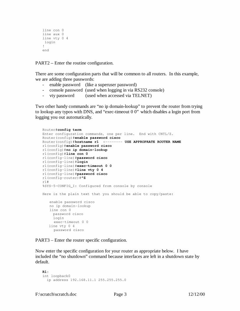
PART2 – Enter the routine configuration. There are some configuration parts that will be common to all routers. In this example, we are adding three passwords:
- enable password (like a superuser password) - console password (used when logging in via RS232 console) - vty password (used when accessed via TELNET)
Two other handy commands are “no ip domain-lookup” to prevent the router from trying to lookup any typos with DNS, and “exec-timeout 0 0” which disables a login port from logging you out automatically.
Router#config term Enter configuration commands, one per line. End with CNTL/Z. Router(config)#enable password cisco Router(config)#hostname r1 <-------- USE APPROPRATE ROUTER NAME r1(config)#enable password cisco r1(config)#no ip domain-lookup r1(config)#line con 0 r1(config-line)#password cisco r1(config-line)#login r1(config-line)#exec-timeout 0 0 r1(config-line)#line vty 0 4 r1(config-line)#password cisco r1(config-router)#^Z r1# %SYS-5-CONFIG_I: Configured from console by console Here is the plain text that you should be able to copy/paste: enable password cisco no ip domain-lookup line con 0 password cisco login exec-timeout 0 0 line vty 0 4 password cisco
PART3 – Enter the router specific configuration. Now enter the specific configuration for your router as appropriate below. I have included the “no shutdown” command because interfaces are left in a shutdown state by default.
R1: int loopback0 ip address 192.168.11.1 255.255.255.0

F:\scratch\scratch.doc Page 4 12/12/00
no shutdown int serial1/2 ip address 192.168.12.1 255.255.255.0 no shutdown int serial 1/3 ip address 192.168.13.1 255.255.255.0 no shutdown int ethernet 2/0 ip address 192.168.10.1 255.255.255.0 no shutdown int ethernet 2/1 ip address 192.168.20.1 255.255.255.0 no shutdown int ethernet 2/2 ip address 192.168.30.1 255.255.255.0 no shutdown int ethernet 2/3 ip address 192.168.40.1 255.255.255.0 no shutdown int ethernet 2/4 ip address 192.168.50.1 255.255.255.0 no shutdown int ethernet 2/5 ip address 192.168.60.1 255.255.255.0 no shutdown router rip network 192.168.10.0 network 192.168.20.0 network 192.168.30.0 network 192.168.40.0 network 192.168.50.0 network 192.168.60.0 network 192.168.12.0 network 192.168.13.0 network 192.168.11.0 R2: int loopback0 ip address 192.168.22.2 255.255.255.0 no shutdown int serial1/1 ip address 192.168.12.2 255.255.255.0 clock rate 2000000 no shutdown int serial 1/3 ip address 192.168.23.2 255.255.255.0 no shutdown int serial 1/4 ip address 192.168.24.2 255.255.255.0 no shutdown router rip network 192.168.12.0 network 192.168.22.0 network 192.168.23.0 network 192.168.24.0 R3: int loopback0 ip address 192.168.33.3 255.255.255.0 no shutdown int serial1/1 ip address 192.168.13.3 255.255.255.0 clock rate 2000000

F:\scratch\scratch.doc Page 5 12/12/00
no shutdown int serial 1/2 ip address 192.168.23.3 255.255.255.0 clock rate 2000000 no shutdown int serial 1/4 ip address 192.168.34.3 255.255.255.0 no shutdown int serial 1/6 ip address 192.168.36.3 255.255.255.0 no shutdown router rip network 192.168.13.0 network 192.168.23.0 network 192.168.33.0 network 192.168.34.0 network 192.168.36.0 R4: int loopback0 ip address 192.168.44.4 255.255.255.0 no shutdown int serial1/2 ip address 192.168.24.4 255.255.255.0 clock rate 2000000 no shutdown int serial 1/3 ip address 192.168.34.4 255.255.255.0 clock rate 2000000 no shutdown int fddi0/0 ip address 192.168.45.4 255.255.255.0 no shutdown router rip network 192.168.24.0 network 192.168.34.0 network 192.168.44.0 network 192.168.45.0 R5: int loopback0 ip address 192.168.55.5 255.255.255.0 no shutdown int FDDI0 ip address 192.168.45.5 255.255.255.0 no shutdown int fastethernet 0 ip address 192.168.70.1 255.255.255.0 media-type 100baseX no shutdown int ethernet 0 ip address 192.168.80.1 255.255.255.0 media-type 10baseT no shutdown int ethernet 1 ip address 192.168.90.1 255.255.255.0 media-type 10baseT no shutdown router rip network 192.168.45.0 network 192.168.55.0 network 192.168.70.0 network 192.168.80.0

F:\scratch\scratch.doc Page 6 12/12/00
network 192.168.90.0 R6: int loopback0 ip address 192.168.66.6 255.255.255.0 no shutdown int serial 1 ip address 192.168.36.6 255.255.255.0 clock rate 2000 no shutdown router rip network 192.168.36.0 network 192.168.66.0 default-metric 5
PART4 – Test the network. By default, Cisco routers send out Cisco Discovery Protocol (CDP) packets. As your router hears CDP packets, it maintains a table of adjacent devices. Display your CDP neighbors with the command “show cdp neighbor”. You should see a listing like this if all is working correctly.
r1#show cdp nei Capability Codes: R - Router, T - Trans Bridge, B - Source Route Bridge S - Switch, H - Host, I - IGMP, r - Repeater Device ID Local Intrfce Holdtme Capability Platform Port ID r2 Ser 1/2 179 R RP1 Ser 1/1 r3 Ser 1/3 149 R RP1 Ser 1/1 cat1 Eth 2/5 172 T S WS -C3524-XFas 0/6 cat1 Eth 2/4 1 72 T S WS-C3524-XFas 0/5 cat1 Eth 2/3 171 T S WS -C3524-XFas 0/4 cat1 Eth 2/2 171 T S WS -C3524-XFas 0/3 cat1 Eth 2/1 171 T S WS -C3524-XFas 0/2 cat1 Eth 2/0 171 T S WS -C3524-XFas 0/1 r2#show cdp nei Capability Codes: R - Router, T - Trans Bridge, B - Source Route Bridge S - Switch, H - Host, I - IGMP, r - Repeater Device ID Local Intrfce Holdtme Capability Platform Port ID r3 Ser 1/3 135 R RP1 Ser 1/2 r1 Ser 1/1 164 R RP1 Ser 1/2 r4 Ser 1/4 144 R RP1 Ser 1/2 r3#show cdp nei Capability Codes: R - Router, T - Trans Bridge, B - Source Route Bridge S - Switch, H - Host, I - IGMP, r - Repeater Device ID Local Intrfce Holdtme Capability Platform Po rt ID r2 Ser 1/2 151 R RP1 Ser 1/3 r1 Ser 1/1 150 R RP1 Ser 1/3 r4 Ser 1/4 129 R RP1 Ser 1/3 fw/r6 Ser 1/6 136 R 2511 Ser 1 r4#show cdp nei Capability Codes: R - Router, T - Trans Bridge, B - Source Route Bridge S - Switch, H - Host, I - IGMP, r - Repeater Device ID Local Intrfce Holdtme Capab ility Platform Port ID

F:\scratch\scratch.doc Page 7 12/12/00
r2 Ser 1/2 139 R RP1 Ser 1/4 r3 Ser 1/3 169 R RP1 Ser 1/4 r5 Fddi0/0 124 R 4500 Fddi0 r5#show cdp nei Capability Codes: R - Router, T - Trans Bridge, B - Source Route Bridge S - Switch, H - Host, I - IGMP, r - Repeater Device ID Local Intrfce Holdtme Capability Platform Port ID r4 Fddi0 153 R RP1 Fddi0/0 cat1 Eth 1 168 T S WS -C3524-XFas 0/9 cat1 Eth 0 167 T S WS -C3524-XFas 0/8 cat1 Fas 0 167 T S WS -C3524-XFas 0/7 fw/r6#show cdp nei Capability Codes: R - Router, T - Trans Bridge, B - Source Route Bridge S - Switch, H - Host, I - IGMP, r - Repeater Device ID Local Intrfce Holdtme Capability Platform Port ID r3 Ser 1 136 R RP1 Ser 1/6 c2900.cs.fsu.edu Eth 0 179 S WS -C2924M-Fas 0/2
You can display the status of your interfaces with “show ip int brief” for an abbreviated listing, or “show ip int” for a detailed listing. If everything is working, you should have a status of “interface up and line protocol up” on the active interfaces. If you see the status as “administratively down”, it means that your interface is shutdown which can be fixed with a “no shutdown” command issued under the appropriate interface. It is normal for interfaces not used in this lab to be in the default “shutdown” state.
r1#show ip int brief Interface IP-Address OK? Method Status Protocol Fddi0/0 unassigned YES unset administratively down down Serial1/0 unassigned YES unset administratively down down Serial1/1 unassigned YES unset administratively down down Serial1/2 192.168.12.1 YES manual up up Serial1/3 192.168.13.1 YES manual up up Serial1/4 unassigned YES unset administratively down down Serial1/5 unassigned YES unset administratively down down Serial1/6 unassigned YES unset administratively down down Serial1/7 unassigned YES unset administratively down down Ethernet2/0 192.168.10.1 YES manual up up Ethernet2/1 192.168.20.1 YES manual up up Ethernet2/2 192.168.30.1 YES manual up up Ethernet2/3 192.168.40.1 YES man ual up up Ethernet2/4 192.168.50.1 YES manual up up Ethernet2/5 192.168.60.1 YES manual up up Loopback0 192.168.11.1 YES manual up up r1#show int ethernet2/0 Ethernet2/0 is up, line protocol is up Hardware is cxBus Ethernet, address is 0000.0c39.dfc4 (bia 0000.0c39.dfc4) Internet address is 192.168.10.1/24 MTU 1500 bytes, BW 10000 Kbit, DLY 1000 usec, rely 25 5/255, load 1/255 Encapsulation ARPA, loopback not set, keepalive set (10 sec) ARP type: ARPA, ARP Timeout 04:00:00 Last input 00:00:05, output 00:00:05, output hang never Last clearing of "show interface" counters never Queueing strategy: fifo Output queue 0/40, 0 drops; input queue 0/75, 0 drops 5 minute input rate 0 bits/sec, 0 packets/sec

F:\scratch\scratch.doc Page 8 12/12/00
5 minute output rate 0 bits/sec, 0 packets/sec 278 packets input, 36107 bytes, 0 no buffer Received 73 broadcasts, 0 runts, 0 giants 0 input errors, 0 CRC, 0 frame, 0 overrun, 0 ignored, 0 abort 0 input packets with dribble condition detected 498 packets output, 103025 bytes, 0 underruns 0 output errors, 0 collisions, 4 interface resets 0 babbles, 0 late collision, 0 de ferred 0 lost carrier, 0 no carrier 0 output buffer failures, 0 output buffers swapped out
Verify that everything is working by trying to PING each router IP address from both your router and PC. By default, PING will send 5 ICMP echo packets. If the destination responds, exclaimation marks “!” are displayed, otherwise a timeout is indicated by a period “.” Try using the TRACEROUTE utility to trace the path to the other routers. Both the PING and TRACEROUTE commands can be entered without the destination argument to give you extended option choices such as changing the packet size, number of packets, source interface, etc.
r1#ping 192.168.11.1 Sending 5, 100-byte ICMP Echoes to 192.168.11.1, timeout is 2 seconds: !!!!! Success rate is 100 percent (5/5), round-trip min/avg/max = 1/1/4 ms r1#ping 192.168.22.2 Sending 5, 100-byte ICMP Echoes to 192.168.22.2, timeout is 2 seconds: !!!!! Success rate is 100 percent (5/5), round -trip min/avg/max = 4/4/4 ms r1#ping 192.168.33.3 Sending 5, 100-byte ICMP Echoes to 192.168.33.3, timeout is 2 seconds: !!!!! Success rate is 100 percent (5/5), round -trip min/avg/max = 1/2/4 ms r1#ping 192.168.44.4 Sending 5, 100-byte ICMP Echoes to 192.168.44.4, timeout is 2 seconds: !!!!! Success rate is 100 percent (5/5), round-trip min/avg/max = 4/6/8 ms r1#ping 192.168.55.5 Sending 5, 100-byte ICMP Echoes to 192.168.55.5, timeout is 2 seconds: !!!!! Success rate is 100 percent (5/5), round -trip min/avg/max = 4/5/8 ms r1#ping 192.168.66.6 Sending 5, 100-byte ICMP Echoes to 192.168.66.6, timeout is 2 seconds: !!!!! Success rate is 100 percent (5/5), round -trip min/avg/max = 4/5/8 ms r1#traceroute 192.168.55.5 Type escape sequence to abort. Tracing the route to 192.168.55.5 1 192.168.13.2 0 msec 192.168.12.2 0 msec 192.168.13.2 0 msec 2 192.168.24.4 8 msec 192.168.34.2 4 msec 192.168.24.4 4 msec 3 192.168.45.5 4 msec * 0 msec
Display the routing table with “show ip route” and verify you have a route to each IP network.
F:\scratch\scratch.doc Page 9 12/12/00
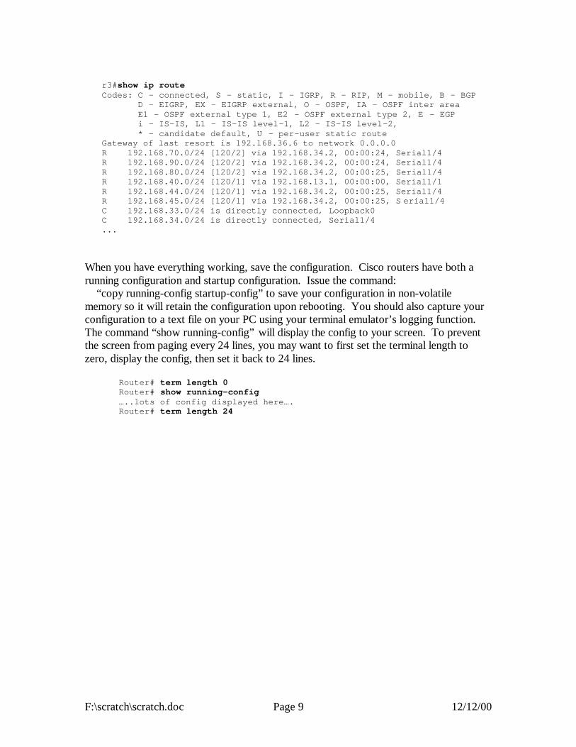
r3#show ip route Codes: C - connected, S - static, I - IGRP, R - RIP, M - mobile, B - BGP D - EIGRP, EX - EIGRP external, O - OSPF, IA - OSPF inter area E1 - OSPF external type 1, E2 - OSPF external type 2, E - EGP i - IS-IS, L1 - IS-IS level-1, L2 - IS-IS level-2, * - candidate default, U - per-user static route Gateway of last resort is 192.168.36.6 to network 0.0.0.0 R 192.168.70.0/24 [120/2] via 192.168.34.2, 00:00:24, Serial1/4 R 192.168.90.0/24 [120/2] via 192.168.34.2, 00:00:24, Serial1/4 R 192.168.80.0/24 [120/2] via 192.168.34.2, 00:00:25, Serial1/4 R 192.168.40.0/24 [120/1] via 192.168.13.1, 00:00:00, Serial1/1 R 192.168.44.0/24 [120/1] via 192.168.34.2, 00:00:25, Serial1/4 R 192.168.45.0/24 [120/1] via 192.168.34.2, 00:00:25, S erial1/4 C 192.168.33.0/24 is directly connected, Loopback0 C 192.168.34.0/24 is directly connected, Serial1/4 ...
When you have everything working, save the configuration. Cisco routers have both a running configuration and startup configuration. Issue the command: “copy running-config startup-config” to save your configuration in non-volatile memory so it will retain the configuration upon rebooting. You should also capture your configuration to a text file on your PC using your terminal emulator’s logging function. The command “show running-config” will display the config to your screen. To prevent the screen from paging every 24 lines, you may want to first set the terminal length to zero, display the config, then set it back to 24 lines.
Router# term length 0 Router# show running-config …..lots of config displayed here…. Router# term length 24

128.
186.
121
.0/2
4
VLAN90VLAN80VLAN70VLAN50 VLAN60VLAN40VLAN30VLAN20
100MbpsFDDI Ring
VLAN10
R3 (7000)
R5 (4500)
R2 (7000)
R1 (7000) R4 (7000)
S1192.168.10.2/24
1Mbps
500Kbps
250K
bps
500K
bps
1MbpsS1/3
S1/1DCE
S1/2DCE S1/3
DCE
S1/4
S1/4
S1/2DCE
S1/1DCE
S1/2
E2/0E1
FDDI0FDDI0/0
scratch.vsd 30-Nov-2000 R.C urci
S1/3
FW/R6 (2511)
COMP SCINETWORK
2Mbps
S1DCE
S1/6
E2/5 E0FA0
36
34
24
23
13
12
10 20 30 40 50 60 70 80 90
45
LINUX
NT
SUN
LINUX
NT
SUN
LINUX
NT
SUN
LINUX
NT
SUN
LINUX
NT
SUN
LINUX
NT
SUN
LINUX
NT
SUN
LINUX
NT
SUN
Addresses are RFC1918private address space,192.168.XXX.0/24where XXX is thenetwork identifierindicated on thisdiagram. RIP v1 isused internally.
LINUX
NT
SUN
5544
33
22
11
66
NAT
START FROM SCRATCH
S2192.168.10.3/24

F:\rip\rip.doc Page 1 12/12/00
INTERNET TEACHING LAB: ROUTING INFORMATION PROTOCOL
192.168.40.0/24
T1 192.168.24.0/24
S1/1DCE
rip-layer1.vsd 18-Oct-2000 R.Curci
CENTER FOR ENTERTAINMENT STUDIES
LOS ANGELES NEW YORK
FSU THEATREFSU FILM
100MbpsFDDI Ring
192.168.45.0/24
R3 (7000)
R5 (4500) R1 (7000)
R4 (7000)
192.168.30.0/24
S1S4
S3
192.168.20.0/24
192.
168.
15.0
/24
192.168.10.0/24
T1 192.168.13.0/24
S2
S1/1DCES1/4
R2 (7000)
S1/4
S1/2 S1/3
E2/0
E2/1E1
FDDI0FDDI0/0
S1/3DCE
S1/2DCE
LOOP0 LOOP0
LOOP0
56Kbps 192.168.34.0/24
56Kbps 192.168.12.0/24
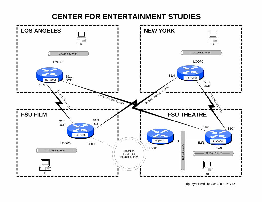
Overview Governor Bush has just been reelected thanks to an effective TV campaign with the help of FSU faculty from the School of Theatre and Film School. In return he has obtained funding for the new FSU Center for Entertainment Studies which will oversee the Film School and School of Theatre. These two schools will retain their existing office space at separate locations tied together with a 100Mbps FSU FDDI backbone. Theatre is located on the FSU Campus while Film is located at the FSU University Center. In this document, these locations will be referenced as “FILM” and “THEATRE”. Funding has been obtained to expand the program and open branch campuses in Los Angles and New York City. You have just been hired as the Network Manager for the Center and your first task is to network your ethernet-based computers at all four geographical locations using the TCP/IP protocol. Your highest bandwidth needs are between “THEATRE” and “FILM”. “NEW YORK” mostly needs to communicate with “THEATRE” while “LOS ANGELES” mostly needs to communicate with “FILM”. All locations must be able to talk with all others, but the major needs are outline above. You have two routers at “THEATRE” and one at each of the other locations. Each site has one router with

F:\rip\rip.doc Page 2 12/12/00
available serial ports for connecting WAN circuits. You have a budget of $7,000 per month for WAN circuit monthly recurring costs and determine the following prices:
MONTHLY RECURRING COSTS CITY1 CITY2 56K bps T1 1.44Mbps TALLAHASSEE LOS ANGELES $500 $3,000 TALLAHASSEE NEW YORK $500 $3,000 LOS ANGELES NEW YORK $500 $3,000 You decide to buy a T1 from “NEW YORK” to “THEATRE” and a second T1 from “LOS ANGELES” to “FILM”, each terminating on different routers. Since you have $1000/month left in your budget you decide to spend it on two slower speed 56K circuits: “NEW YORK” to “FILM” and “LOS ANGELES” to “THEATRE”. For extra redundancy, you decide to terminate these backup circuits on different routers on the Tallahassee end as depicted in the wiring diagram. You decide to use the RIP routing protocol and get everything up and running. Here are your IP address assignments. Note some of the conventions to make addressing a little bit easier. Generally speaking, network masks are /24 unless otherwise specified. Interfaces between routers use the two router numbers in the third octet, i.e. a links from router X to router Y is network 192.168.XY.0 where X is the lower numbered router. Also, on interfaces between routers, the last octet of the address corresponds to the router. For example, note that all interfaces on r4 that go to other router have “4” as the last octet. IP ADDRESS ASSIGNMENTS ROUTER PORT IP ADDRESS R1 E2/0 192.168.10.1/24 R1 E2/1 192.168.15.1/24 R1 S1/2 192.168.12.1/24 R1 S1/3 192.168.13.1/24 R2 LOOP0 192.168.20.1/24 R2 S1/1 192.168.12.2/24 R2 S1/4 192.168.14.2/24 R3 LOOP0 192.168.30.1/24 R3 S1/1 192.168.13.3/24 R3 S1/2 192.168.34.3/24 R4 LOOP0 192.168.40.1/24 R4 S1/2 192.168.24.4/24 R4 S1/3 192.468.34.4/24 R4 FDDI0/0 192.168.45.4/24 R5 E1 192.168.15.5/24 R5 FDDI0 192.168.45.5/24 Your users are complaining that sometimes the network is slow. Investigate using the built-in router tools “ping”, “traceroute”, “ttcp”, “show ip route”, “show cdp neighbor”, and “show ip protocol”. Measure the throughput between the different routers to quantify

F:\rip\rip.doc Page 3 12/12/00
what is “slow.” Why are some things “slow”? What can be gone to correct these problems? What are some of the tradeoffs you have encountered between throughput and fault tolerance. The initial router configurations for all five routers are in file rip-config.txt. You should be able to cut and paste the configurations into the routers. Output from “show ip route” and “show ip protocol” are on file sh-ip-route.txt. Output from “show cdp neighbor” are on file sh-cdp-nei.txt. By just looking at the diagram and routing tables, you should be able to manually determine the route IP packets will take one hop at a time through the network.

F:\rip\rip.doc Page 4 12/12/00
INITIAL ROUTER CONFIGURATIONS: COMMON: service udp-small-servers service tcp-small-servers enable password cisco no ip domain-lookup no ip classless logging buffered line con 0 exec-timeout 0 0 line aux 0 line vty 0 4 password cisco login R1: hostname r2 interface Loopback0 description S3 LAN ip address 192.168.20.1 255.255.255.0 no shutdown interface Fddi0/0 no ip address no shutdown interface Serial1/1 description Link to R1 S1/2 ip address 192.168.12.2 255.255.255.0 bandwidth 56 clockrate 56000 no shutdown interface Serial1/4 description Link to R4 S1/2 ip address 192.168.24.2 255.255.255.0 bandwidth 1544 no shutdown router rip network 192.168.20.0 network 192.168.24.0 network 192.168.12.0 R2: hostname r2 interface Loopback0 description S3 LAN ip address 192.168.20.1 255.255.255.0 no shutdown interface Fddi0/0 no ip address no shutdown interface Serial1/1 description Link to R1 S1/2 ip address 192.168.12.2 255.255.255.0 bandwidth 56 clockrate 56000 no shutdown interface Serial1/4 description Link to R4 S1/2 ip address 192.168.24.2 255.255.255.0 bandwidth 1544 no shutdown router rip network 192.168.20.0 network 192.168.24.0 network 192.168.12.0 R3: hostname r3
interface Loopback0 description S4 LAN ip address 192.168.30.1 255.255.255.0 no shutdown interface Fddi0/0 no ip address no shutdown interface Serial1/1 description Link to R1 S1/3 ip address 192.168.13.3 255.255.255.0 bandwidth 1544 clockrate 2000000 no shutdown interface Serial1/4 description Link to R4 S1/3 ip address 192.168.34.3 255.255.255.0 bandwidth 56 no shutdown router rip network 192.168.30.0 network 192.168.34.0 network 192.168.13.0 R4: hostname r4 interface Loopback0 description S2 LAN ip address 192.168.40.1 255.255.255.0 no shutdown interface Fddi0/0 description Link to R5 FDDI0 ip address 192.168.45.4 255.255.255.0 no shutdown interface Serial1/2 description Link to R2 S1/4 ip address 192.168.24.4 255.255.255.0 bandwidth 1544 clockrate 2000000 no shutdown interface Serial1/3 description Link to R3 S1/4 ip address 192.168.34.4 255.255.255.0 bandwidth 56 clockrate 56000 no shutdown router rip network 192.168.24.0 network 192.168.34.0 network 192.168.40.0 network 192.168.45.0 R5: hostname r5 interface Ethernet1 description Link to R1 E2/1 ip address 192.168.15.5 255.255.255.0 media-type 10BaseT no shutdown interface Fddi0 description Link to R4 FDDI0/0 ip address 192.168.45.5 255.255.255.0 no keepalive no shutdown router rip network 192.168.45.0 network 192.168.15.0
192.168.40 .0/24
T1 192.168.24 .0/24
S1/1DCE
rip-layer1.vsd 18-Oct-2000 R.Curci
CENTER FOR ENTERTAINMENT STUDIES
LOS ANGELES NEW YORK
FSU THEATREFSU FILM
100MbpsFDDI Ring
192.168.45 .0/24
R3 (7000)
R5 (4500) R1 (7000)
R4 (7000)
192.168.30 .0/24
S1S4
S3
192.168.20 .0/24
192.
168.
15.0
/24
192.168.10 .0/24
T1 192.168.13.0/24
S2
S1/1DCES1/4
R2 (7000)
S1/4
S1/2 S1/3
E2/0
E2/1E1
FDDI0FDDI0/0
S1/3DCE
S1/2DCE
LOOP0 LOOP0
LOOP0
56Kbps
192.
168. 34.0/24
56Kbps 192.168. 12.0/24

F:\igp\igp.doc Page 1 12/12/00
INTERNET TEACHING LAB: Interior Gateway Protocol (IGP) LAB
Overview In this lab, we will explore some common interior gateway protocols—
- RIP version 1 (Routing Information Protocol) - OSPF (Open Shortest Path First) - EIGRP (Enhanced Interior Gateway Routing Protocol) - IGRP (Interior Gateway Routing Protocol) - ISIS (Intermediate System – Intermediate System
You will be configuring routers R1 through R5, while router R6 is preconfigured for EIGRP protocol on serial port S1 and will supply a default route for the lab network. For each of the above 5 routing protocols, three of the routers will participate as follows:
- RIP: R1,R2,R3 - OSPF: R2,R3,R4 - EIGRP: R3,R4,R5 - IGRP: R4,R5,R1 - ISIS: R5,R1,R2

F:\igp\igp.doc Page 2 12/12/00
Each of your routers will have a loopback and FDDI interface that needs to participate in all three appropriate routing protocols. Additionally, R1 and R5 will need the IGRP protocol on all ethernet and fast ethernet interfaces. Router R3 will need EIGRP on interface S1/6 to learn the default route to the outside world. PART1 – IP ADDRESSING Configure IP addresses as listed in the table below. Loopback0 interfaces need to be created if they do not exist and any other loopback addresses removed. Any interfaces not explicitly mentioned below, should be shut down. Once addressed, verify you have appropriate physical connectivity with “show cdp neighbors”. Verify that additional interfaces are shut down with “show ip interface brief.” At this point, you should be able to view your IP routing table with “show ip route” and should only see directly connected routes. Verify that you can PING the other router’s FDDI IP addresses. You will not be able to PING the other router’s loopback addresses because you will not have routes for them until later in this lab exercise. Make certain you have no static routes including default routes. Rtr Interface IP Address/Mask Routing Protocol(s) R1 Loopback0 192.168.11.1/24 RIPv1,OSPF,IGRP Fddi0/0 192.168.1.1/24 RIPv1,OSPF,IGRP Ethernet2/0 192.168.10.1/24 IGRP Ethernet2/1 192.168.20.1/24 IGRP Ethernet2/2 192.168.30.1/24 IGRP Ethernet2/3 192.168.40.1/24 IGRP Ethernet2/4 192.168.50.1/24 IGRP Ethernet2/5 192.168.60.1/24 IGRP R2 Loopback0 192.168.22.2/24 RIPv1,OSPF,ISIS Fddi0/0 192.168.1.2/24 RIPv1,OSPF,ISIS R3 Loopback0 192.168.33.3/24 RIPv1,OSPF,EIGRP Fddi0/0 192.168.1.3/24 RIPv1,OSPF,EIGRP Serial1/6 192.168.36.3/24 EIGRP R4 Loopback0 192.168.44.4/24 OSPF,EIGRP,IGRP Fddi0/0 192.168.1.4/24 OSPF,EIGRP,IGRP R5 Loopback0 192.168.55.5/24 EIGRP,IGRP,ISIS Fddi0 192.168.1.5/24 EIGRP,IGRP,ISIS FastEther0 192.168.70.1/24 IGRP Ethernet0 192.168.80.1/24 IGRP Ethernet1 192.168.90.1/24 IGRP Debug Mode

F:\igp\igp.doc Page 3 12/12/00
Cisco routers have a debug mode that can be helpful in debugging routing protocols, especially distance vector protocols. This mode should never be used on a production network because a large number of messages can be generated that can even cause a router to crash. To turn on your console window to receive debug messages, use the command “term monitor” or to turn it off “term no monitor.” To turn on a particular debug mode, use the command “debug XXX” such as “debug ip routing” or turn it off with “undebug all”. The command “debug ?” will show you your options. You can turn on more than one debug mode, or even turn them all on with “debug all”. To see which debug modes are active, use “show debug.” PART2 – RIP (R1,R2,R3 Only) Configure RIP on your router’s FDDI and Loopback0 interface. The following commands may be helpful.
- show ip route - show ip route rip - show ip protocol - debug ip rip - debug ip rip events
PART3 – OSPF (R2,R3,R4 Only) Configure OSPF on your router’s FDDI and Loopback0 interface. Use process ID 100. Place all OSPF interfaces in the special OSPF backbone area 0. The following commands may be helpful.
- show ip route - show ip route ospf - show ip protocol - show ip ospf neighbor - show ip ospf interface - show ip ospf database - show ip ospf database database-summary - debug ip ospf event - debug ip ospf packet
PART4 – EIGRP (R3,R4,R5 Only) Configure EIGRP on your router’s FDDI and Loopback0 interfaces. Use autonomous system number 100. The following commands may be helpful.
- show ip route

F:\igp\igp.doc Page 4 12/12/00
- show ip route eigrp - show ip protocol - show ip eigrp interfaces - show ip eigrp neighbors - show ip eigrp topology - show ip eigrp traffic - debug ip eigrp neighbor
PART5 – IGRP (R4,R5,R1 Only) Configure IGRP on your router’s FDDI and Loopback0 inerfaces. On R1 and R5, also configure all ethernet and fast ethernet ports for IGRP. Use autonomous system 100. The following commands may be helpful.
- show ip route - show ip route igrp - show ip protocol - debug ip igrp events - debug ip igrp transactions
PART6 – ISIS (R5,R1,R2 Only) Configure ISIS on your router’s FDDI and Loopback0 interfaces. Use “100” for your ISO Routing Tag. ISIS incorporates an adrea number and MAC address into a “Network Entity Title” We will use area 1 and make up a dummy MAC address in the form NNNN.NNNN.NNNN for router N. Use the following Network Entity Title, substituting your router number for the letter N: “00.0001.NNNN.NNNN.NNNN.00”. In this example, the “00.0001” represents the area number in hex, while the “NNNN.NNNN.NNNN.00” is an identifier for your router in hex. The following commands may be helpful.
- show ip route - show ip route isis - show ip protocol - show isis database
PART7 – Route Redistribution (R3 Only)

F:\igp\igp.doc Page 5 12/12/00
Router R3 should be receiving EIGRP routes from R6 including a default route (0.0.0.0) and a route for R6’s Loopback0 interface 192.168.66.6. Some of the routers, however, may not be getting these routes. On R3 only, redistribute all RIP routes into both RIP and OSPF. For RIP, use a hop count/metric of 10. Verify with “show ip route” that you can see both 0.0.0.0 and 192.168.66.6/24 from all routers. PART8 – Verification Verify that everything is working. You can display the routing tables with “show ip route” which should look like the the output below. Note that the letter designation to the left of each routing entry indicates which protocol put the route in the routing table. When the same route is learned by multiple protocols, the protocol with the lowest administrative distance is used. Administrative distance is like a believability factor. Administrative distances for some common protocols are listed in the table below. You will notice in the output below, that the “show ip route” output entries indicate two numbers in square brackets, administrative distance and route metric. PROTOCOL ADMIN.DIST. Connected 0Static 1EIGRP 90IGRP 100ISIS 115OSPF 110ISIS 115 Codes: C - connected, S - static, I - IGRP, R - RIP, M - mobile, B - BGP D - EIGRP, EX - EIGRP external, O - OSPF, IA - OSPF inter area E1 - OSPF external type 1, E2 - OSPF external type 2, E - EGP i - IS-IS, L1 - IS-IS level-1, L2 - IS-IS level-2, * - candidate default U - per-user static route R1: Gateway of last resort is 192.168.1.3 to network 0.0.0.0 R 192.168.66.0/24 [120/10] via 192.168.1. 3, 00:00:06, Fddi0/0 I 192.168.90.0/24 [100/1110] via 192.168.1.5, 00:01:08, Fddi0/0 I 192.168.80.0/24 [100/1110] via 192.168.1.5, 00:01:08, Fddi0/0 C 192.168.40.0/24 is directly connected, Ethernet2/3 I 192.168.44.0/24 [100/610] via 192.168.1. 4, 00:01:19, Fddi0/0 R 192.168.33.0/24 [120/1] via 192.168.1.3, 00:00:06, Fddi0/0 R 192.168.36.0/24 [120/10] via 192.168.1.3, 00:00:06, Fddi0/0 C 192.168.60.0/24 is directly connected, Ethernet2/5 C 192.168.50.0/24 is directly connected, Ethern et2/4 I 192.168.55.0/24 [100/610] via 192.168.1.5, 00:01:08, Fddi0/0 C 192.168.10.0/24 is directly connected, Ethernet2/0 C 192.168.11.0/24 is directly connected, Loopback0 C 192.168.1.0/24 is directly connected, Fddi0/0 C 192.168.30.0/24 is directly connected, Ethernet2/2 C 192.168.20.0/24 is directly connected, Ethernet2/1 i L1 192.168.22.0/24 [115/20] via 192.168.1.2, Fddi0/0 R* 0.0.0.0/0 [120/10] via 192.168.1.3, 00:00:06, Fddi0/0
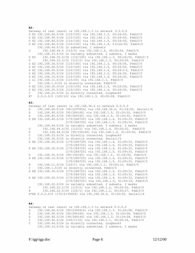
F:\igp\igp.doc Page 6 12/12/00
R2: Gateway of last resort is 192.168.1.3 to network 0.0.0.0 O E2 192.168.66.0/24 [110/100] via 192.168.1.3, 00:26:50, Fddi0/0 O E2 192.168.90.0/24 [110/100] via 192.168.1.5, 00:26:50, Fddi0/0 O E2 192.168.80.0/24 [110/100] via 192.168.1.5, 00:26:50, Fddi0/0 O E2 192.168.40.0/24 [110/100] via 192.168.1.4, 0 0:26:50, Fddi0/0 192.168.44.0/32 is subnetted, 1 subnets O 192.168.44.4 [110/2] via 192.168.1.4, 00:26:50, Fddi0/0 192.168.33.0/24 is variably subnetted, 2 subnets, 2 masks O E2 192.168.33.0/24 [110/100] via 192.168.1.3, 00:26:50, Fddi0/ 0 O 192.168.33.3/32 [110/2] via 192.168.1.3, 00:26:50, Fddi0/0 O E2 192.168.36.0/24 [110/100] via 192.168.1.3, 00:26:50, Fddi0/0 O E2 192.168.60.0/24 [110/100] via 192.168.1.4, 00:26:50, Fddi0/0 O E2 192.168.50.0/24 [110/100] via 192.168.1.4, 00:26:5 0, Fddi0/0 O E2 192.168.55.0/24 [110/100] via 192.168.1.5, 00:26:50, Fddi0/0 O E2 192.168.10.0/24 [110/100] via 192.168.1.4, 00:26:50, Fddi0/0 i L1 192.168.11.0/24 [115/20] via 192.168.1.1, Fddi0/0 C 192.168.1.0/24 is directly connected, Fddi0/0 O E2 192.168.30.0/24 [110/100] via 192.168.1.4, 00:26:50, Fddi0/0 O E2 192.168.20.0/24 [110/100] via 192.168.1.4, 00:26:50, Fddi0/0 C 192.168.22.0/24 is directly connected, Loopback0 R* 0.0.0.0/0 [120/10] via 192.168.1.3, 00:00:08, Fddi0/0 R3: Gateway of last resort is 192.168.36.6 to network 0.0.0.0 D 192.168.66.0/24 [90/2297856] via 192.168.36.6, 01:24:50, Serial1/6 D 192.168.90.0/24 [90/284160] via 192.168.1.5, 01:24:50, Fddi0/0 D 192.168.80.0/24 [90/284160] via 192.168.1.5, 01:24:50, Fddi0/0 D EX 192.168.40.0/24 [170/286720] via 192.168.1.4, 01:09:33, Fddi0/0 [170/286720] via 192.168.1.5, 01:09:33, Fddi0/0 192.168.44.0/24 is variably subnetted, 2 subnets, 2 masks O 192.168.44.4/32 [110/2] via 192.168.1.4, 00:26:52, Fddi0/0 D 192.168.44.0/24 [90/156160] via 192.168.1.4, 01:24:50, Fddi0/0 C 192.168.33.0/24 is directly connected, Loopback0 C 192.168.36.0/24 is directly connected, Serial1/6 D EX 192.168.60.0/24 [170/286720] via 192.168.1.4, 01:09:33, Fddi0/0 [170/286720] via 192.168.1.5, 01:09:33, Fddi0/0 D EX 192.168.50.0/24 [170/286720] via 192.168.1.4, 01:09:33, Fddi0/0 [170/286720] via 192.168.1.5, 01:09:33, Fddi0/0 D 192.168.55.0/24 [90/156160] via 192.168.1.5 , 01:24:50, Fddi0/0 D EX 192.168.10.0/24 [170/286720] via 192.168.1.4, 01:09:33, Fddi0/0 [170/286720] via 192.168.1.5, 01:09:33, Fddi0/0 R 192.168.11.0/24 [120/1] via 192.168.1.1, 00:00:10, Fddi0/0 C 192.168.1.0/24 is directly connected, Fddi0/0 D EX 192.168.30.0/24 [170/286720] via 192.168.1.4, 01:09:33, Fddi0/0 [170/286720] via 192.168.1.5, 01:09:33, Fddi0/0 D EX 192.168.20.0/24 [170/286720] via 192.168.1.4, 01:09:33, Fddi0/0 [170/286720] via 192.168.1.5, 01:09:33, Fddi0/0 192.168.22.0/24 is variably subnetted, 2 subnets, 2 masks O 192.168.22.2/32 [110/2] via 192.168.1.2, 00:26:52, Fddi0/0 R 192.168.22.0/24 [120/1] via 192.168.1.2, 00:00:27, Fddi0/0 D*EX 0.0.0.0/0 [170/2195456] via 192.168.36.6, 01:24:50, Serial1/6 R4: Gateway of last resort is 192.168.1.3 to network 0.0.0.0 D 192.168.66.0/24 [90/2300416] via 192.168.1.3, 01:24:08, Fddi0/0 D 192.168.90.0/24 [90/284160] via 192.168.1.5, 01:24:08, Fddi0/0 D 192.168.80.0/24 [90/284160] via 192.168.1.5, 01:24:08, Fddi0/0 I 192.168.40.0/24 [100/1110] via 192.168.1.1, 00:00:36, Fddi0/0 C 192.168.44.0/24 is directly connected, Loopback0 192.168.33.0/24 is variably subnetted, 2 subnets, 2 masks

F:\igp\igp.doc Page 7 12/12/00
D 192.168.33.0/24 [90/156160] via 192.168.1.3, 01:24:08, Fddi0/0 O 192.168.33.3/32 [110/2] via 192.168.1.3, 00:26:55, Fddi0/0 D 192.168.36.0/24 [90/2172416] via 192.168.1.3, 01:24:08, Fddi0/0 I 192.168.60.0/24 [100/1110] via 192.168.1.1, 00:00:36, Fddi0 /0 I 192.168.50.0/24 [100/1110] via 192.168.1.1, 00:00:36, Fddi0/0 D 192.168.55.0/24 [90/156160] via 192.168.1.5, 01:24:08, Fddi0/0 I 192.168.10.0/24 [100/1110] via 192.168.1.1, 00:00:36, Fddi0/0 I 192.168.11.0/24 [100/610] via 192.168.1.1, 00: 00:36, Fddi0/0 C 192.168.1.0/24 is directly connected, Fddi0/0 I 192.168.30.0/24 [100/1110] via 192.168.1.1, 00:00:36, Fddi0/0 I 192.168.20.0/24 [100/1110] via 192.168.1.1, 00:00:36, Fddi0/0 192.168.22.0/32 is subnetted, 1 subnets O 192.168.22.2 [110/2] via 192.168.1.2, 00:26:55, Fddi0/0 D*EX 0.0.0.0/0 [170/2198016] via 192.168.1.3, 01:24:08, Fddi0/0 R5: Gateway of last resort is 192.168.1.3 to network 0.0.0.0 D 192.168.44.0/24 [90/156160] via 192.168.1.4, 03:57:37, Fddi0 C 192.168.90.0/24 is directly connected, Ethernet1 I 192.168.30.0/24 [100/1110] via 192.168.1.1, 00:00:38, Fddi0 I 192.168.60.0/24 [100/1110] via 192.168.1.1, 00:00:38, Fddi0 I 192.168.10.0/24 [100/1110] via 192.168.1.1, 00:00:38, Fddi0 I 192.168.40.0/24 [100/1110] via 192.168.1.1, 00:00:38, Fddi0 I 192.168.11.0/24 [100/610] via 192.168.1.1, 00:00:38, Fddi0 C 192.168.55.0/24 is directly connected, Loopback0 C 192.168.80.0/24 is directly connected, Ethernet0 I 192.168.20.0/24 [100/1110] via 1 92.168.1.1, 00:00:38, Fddi0 D 192.168.66.0/24 [90/2300416] via 192.168.1.3, 01:26:36, Fddi0 D 192.168.36.0/24 [90/2172416] via 192.168.1.3, 01:26:38, Fddi0 i L1 192.168.22.0/24 [115/20] via 192.168.1.2, Fddi0 I 192.168.50.0/24 [100/1110] via 192.1 68.1.1, 00:00:38, Fddi0 C 192.168.1.0/24 is directly connected, Fddi0 D 192.168.33.0/24 [90/156160] via 192.168.1.3, 01:26:38, Fddi0 D*EX 0.0.0.0/0 [170/2198016] via 192.168.1.3, 01:26:36, Fddi0

F:\igp\igp.doc Page 8 12/12/00

igp.vsd 08-Nov-2000 R .Curci
IGP LAB
FDDIRing
R1
R2
R3
R4
R5
FDDIRing
R1
R2
R3
R4
R5
FDDIRing
R1
R2
R3
R4
R5
FDDIRing
R1
R2
R3
R4
R5
FDDIRing
R1
R2
R3
R4
R5
RIP v1 OSPF
EIGRP
IGRP
ISIS
R6
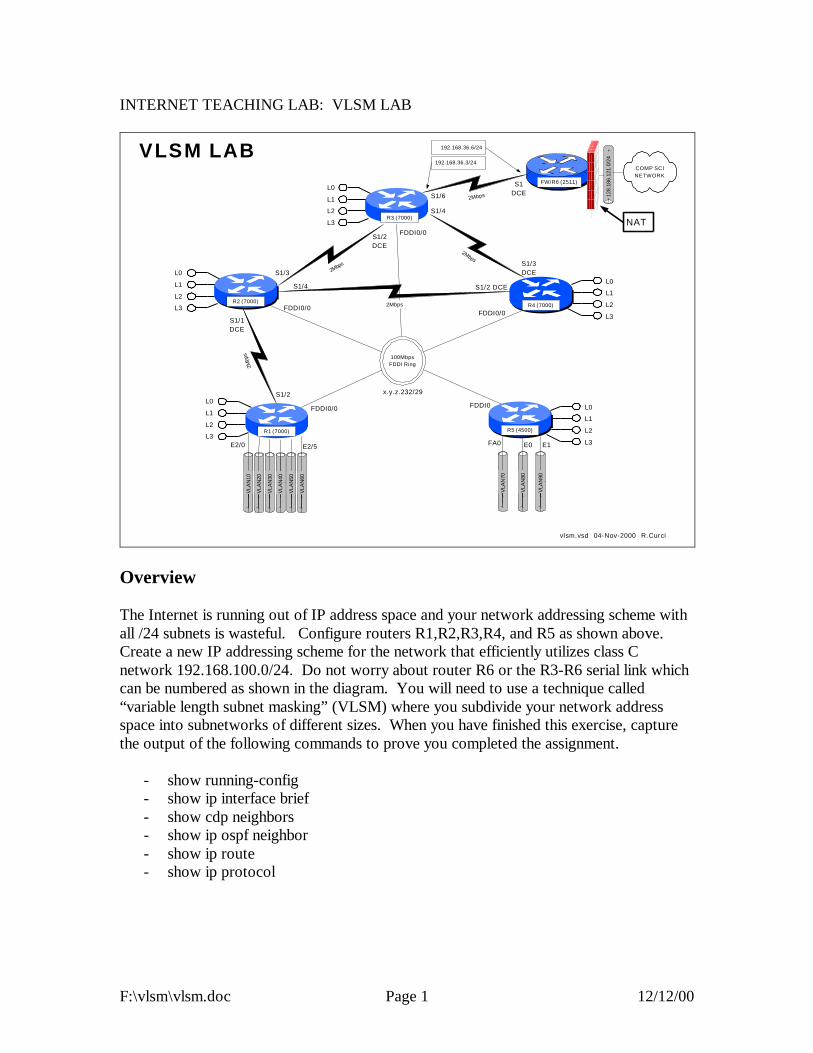
F:\vlsm\vlsm.doc Page 1 12/12/00
INTERNET TEACHING LAB: VLSM LAB
VLA
N90
VLA
N80
VLA
N70
VLA
N60
VLA
N50
VLA
N40
VLA
N30
VLA
N20
128.
186.
121.
0/24
100MbpsFDDI Ring
VLA
N10
R5 (4500)
R2 (7000)
R1 (7000)
R4 (7000)
2Mbps
2Mbps
R3 (7000)
S1/3S1/3DCE
S1/6
S1/1DCE
E2/0 E1
FDDI0
vlsm.vsd 04-Nov-2000 R.Curci
FW/R6 (2511)
COMP SCINETWORK
2Mbps
S1DCE
E2/5 E0FA0
NAT
VLSM LAB
2Mbp
s
S1/2
2Mbps
L0
L1
L2
L3
L0
L1
L2
L3
L0
L1
L2
L3
L0
L1
L2
L3
L0
L1
L2
L3
FDDI0/0
FDDI0/0
FDDI0/0
FDDI0/0
S1/4
S1/2DCE
S1/2 DCE
192.168.36.3/24
192.168.36.6/24
S1/4
x.y.z.232/29
Overview The Internet is running out of IP address space and your network addressing scheme with all /24 subnets is wasteful. Configure routers R1,R2,R3,R4, and R5 as shown above. Create a new IP addressing scheme for the network that efficiently utilizes class C network 192.168.100.0/24. Do not worry about router R6 or the R3-R6 serial link which can be numbered as shown in the diagram. You will need to use a technique called “variable length subnet masking” (VLSM) where you subdivide your network address space into subnetworks of different sizes. When you have finished this exercise, capture the output of the following commands to prove you completed the assignment.
- show running-config - show ip interface brief - show cdp neighbors - show ip ospf neighbor - show ip route - show ip protocol

F:\vlsm\vlsm.doc Page 2 12/12/00
PART 1 – IP Addressing On each router R1 through R5, create four loopback interfaces that will support the following number of hosts.
INTERFACE # HOSTS loopback0 14 hosts loopback1 6 hosts loopback2 2 hosts loopback3 2 hosts
Begin by looking at each network and deciding how many host addresses must be supported to figure out the size of each subnet. You must do this with maximum efficiency as there no extra addresses, only exactly enough to solve this problem. For each of the five routers, select the loopback subnets such that they can be summarized. If you do not understand the concept of summarization, read up on CIDR – Classless Internet Domain Routing. You will need to use the command “ip classless” on your router to make it ignore the classfull (i.e. Class A, B, C) network mask assumptions. Since we will be using all subnets including subnet zero, you will also need the command “ip subnet-zero” in your configuration. PART 2 – OSPF Routing When using variable length subnet masks in your network, you will need an IP routing protocol that supports VLSM such as OSPF (Open Shortest Path First). Configure OSPF as your only routing protocol. All FDDI, Ethernet, FastEthernet, and Serial interfaces should be in area 0. Place the loopback addresses on each of the five routers in a separate area corresponding to the router identifier. For example, the loopback addresses on router 3 should be in area 3. You may wish to use the following commands to help debug your OSPF configuration:
- show ip ospf neighbor - show ip ospf database - show ip ospf database-summary - show ip ospf interface - show ip route - show ip route ospf - show ip protocol
PART 3 – Address Summarization In large networks like the Internet, the number of network routes that fit in the routing table becomes a limiting factor. In the mid 1980s with the exponential growth of the Internet, many predicted the collapse of the Internet backbone due to the growing size of

F:\vlsm\vlsm.doc Page 3 12/12/00
the routing tables. This problem was helped by the creation of CIDR – Classless Internet Domain Routing, which summarizes network blocks without regard to the classfull network designations. As of this writing, there are approximately 90,000 routes on the Internet, a number that would be much higher without CIDR. Routing protocols like OSPF are very scalable when used with hierarchical network addressing schemes that support summarization. Your routers should be advertising their loopback addresses as individual routes, each creating its own routing table entry in the routing tables of the other routers. For each of the five routers, reconfigure OSPF to advertise a single summary route for all four loopback addresses instead of advertising them individually. Because each router is participating in more than one OSPF area, it is an autonomous system boundary router (ASBR). ASBRs can summarize the routes within their non-zero areas into the core area zero to reduce the number of routes the core area zero routers must keep in their tables. Verify everything is working by studying the output of the commands “show ip route”, “show ip protocol”, “show ip ospf neighbor”, “show ip ospf database database-summary”, ”show ip ospf interface”, etc. If you simply type “show ip ospf ?” you will see the various options available. PART 4 – Network Assurance Assign new IP addresses for your PCs using the new IP address scheme. Note that not only your IP address, but also your gateway, broadcast address, netmask, and network addresses have changed. Verify everything is reachable by scanning the lab network from a UNIX PC using the NMAP utility. This utility can be found at www.insecure.org/nmap. Be sure to only scan within the lab network because probes outside the lab will cause firewalls and intrusion detection systems to complain and are presently treated by law enforcement as attempted unauthorized access. PART 5 – GateD / Extra Credit Configure your Linux system to use GateD by modifying file /etc/gated.conf. Configure your system to use the OSPF routing protocol on its ethernet port which should be in area zero. Use the command “netstat –rn” to display your routing table. You should see routes for all networks in area zero plus the summary routes for non-area zero networks. You should also see a default route sometimes listed as ‘0.0.0.0’. Be sure to remove any static default route on your system, as you should learn the default dynamically from OSPF.
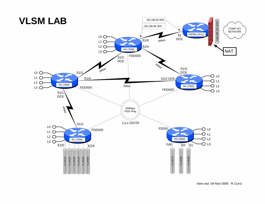
VLA
N90
VLA
N80
VLA
N70
VLA
N60
VLA
N50
VLA
N40
VLA
N30
VLA
N20
128.
186.
121
.0/2
4
100MbpsFDDI Ring
VLA
N10
R5 (4500)
R2 (7000)
R1 (7000)
R4 (7000)
2Mbps
2Mbps
R3 (7000)
S1/3S1/3DCE
S1/6
S1/1DCE
E2/0 E1
FDDI0
vlsm.vsd 04-Nov-2000 R.Curci
FW/R6 (2511)
COMP SCINETWORK
2Mbps
S1DCE
E2/5 E0FA0
NAT
VLSM LAB
2Mbp
s
S1/2
2Mbps
L0
L1L2
L3
L0
L1
L2L3
L0L1
L2
L3
L0
L1
L2L3
L0
L1L2
L3
FDDI0/0
FDDI0/0
FDDI0/0
FDDI0/0
S1/4
S1/2DCE
S1/2 DCE
192.168.36.3/24
192.168.36.6/24
S1/4
x.y.z.232/29
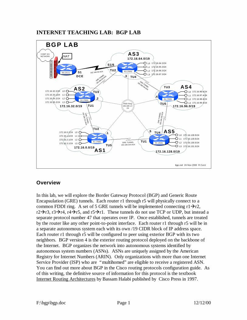
F:\bgp\bgp.doc Page 1 12/12/00
INTERNET TEACHING LAB: BGP LAB
128.
186.
121.
0/24
COMP SCINETWORK NAT
bgp.vsd 24-Nov-2000 R.Curci
BGP LAB
AS4
R5 (4500)
R2 (7000)
R1 (7000)
R4 (7000)
R3 (7000)
GRE TUNNEL
192.16
8.223.
0/24
GR
E TU
NN
EL
192.168.212.0/24
GRE TUNNEL
192.168.234.0/24
GR
E T
UN
NE
L19
2.16
8.24
5.0/
24
GRE TUNNEL192.168.215.0/24
AS1
AS3
AS5
AS2
172.16.0.0/19172.16.128.0/19
172.16.96.0/19172.16.32.0/19
TU3
TU2
TU4
TU3
TU5
TU4
TU1TU5
TU2
TU1
172.16.64.0/19
.2
.5.1
.4
.3R6 (2511) 192.168.36.0/24
S1/6
S1DCE
L0
L1
L2
L3
L0
L1
L2
L3
L0
L1
L2
L3
L0
L1
L2
L3
L0
L1
L2
L3
172.16.64.3/24
172.16.65.3/24
172.16.66.3/24
172.16.67.3/24
172.16.96.4/24
172.16.97.4/24
172.16.98.4/24
172.16.99.4/24
172.16.128.5/24
172.16.129.5/24
172.16.130.5/24
172.16.131.5/24
172.16.32.2/24
172.16.33.2/24
172.16.34.2/24
172.16.35.2/24
172.16.0.1/24
172.16.1.1/24
172.16.2.1/24
172.16.3.1/24
FDDI Ring192.168.1.0
/24
Overview In this lab, we will explore the Border Gateway Protocol (BGP) and Generic Route Encapsulation (GRE) tunnels. Each router r1 through r5 will physically connect to a common FDDI ring. A set of 5 GRE tunnels will be implemented connecting r1àr2, r2àr3, r3àr4, r4àr5, and r5àr1. These tunnels do not use TCP or UDP, but instead a separate protocol number 47 that operates over IP. Once established, tunnels are treated by the router like any other point-to-point interface. Each router r1 through r5 will be in a separate autonomous system each with its own /19 CIDR block of IP address space. Each router r1 through r5 will be configured to peer using exterior BGP with its two neighbors. BGP version 4 is the exterior routing protocol deployed on the backbone of the Internet. BGP organizes the network into autonomous systems identified by autonomous system numbers (ASNs). ASNs are uniquely assigned by the American Registry for Internet Numbers (ARIN). Only organizations with more than one Internet Service Provider (ISP) who are “multihomed” are eligible to receive a registered ASN. You can find out more about BGP in the Cisco routing protocols configuration guide. As of this writing, the definitive source of information for this protocol is the textbook Internet Routing Architectures by Bassam Halabi published by Cisco Press in 1997.

F:\bgp\bgp.doc Page 2 12/12/00
Here is the FSU autonomous system number registration record at ARIN:
acns% whois -h whois.arin.net 2553 Florida State University (ASN-FSU) Academic Computing & Network Services Room 200, Sliger Building 2035 East Paul Dirac Drive Tallahassee, FL 32310 Autonomous System Name: FSU-AS Autonomous System Number: 2553 Coordinator: Garner, Lee [Systems Programmer] (LG36 -ARIN) [email protected] 850-644-2592 (FAX) 850-644-8722 Record last updated on 25-Jan-1995. Database last updated on 24-Nov-2000 18:13:50 EDT.
Here is a summary of BGP peering sessions on the FSU BFS-7507 router. Note that our peer at IP address 199.44.5.225 (Sprint) is sending us over 92,000 prefixes.
bfs-7507#show ip bgp sum BGP router identifier 128.186.253.5, local AS number 2553 BGP table version is 10339797, main routing table version 10339797 93124 network entries and 293284 paths using 19684376 bytes of memory 44120 BGP path attribute entries using 2294812 bytes of memory 23517 BGP AS-PATH entries using 634144 bytes of memory 32 BGP community entries using 852 bytes of memory 1772 BGP route-map cache entries using 28352 bytes of memory 34843 BGP filter-list cache entries using 418116 bytes of memory 109503 received paths for inbound soft reconfiguration BGP activity 657129/958415 prefixes, 6401589 /6108305 paths, scan interval 15 secs Neighbor V AS MsgRcvd MsgSent TblVer InQ OutQ Up/Down State/PfxRcd 128.186.250.194 4 7202 72889 72879 10339797 0 0 7w1d 1 128.186.250.201 4 3996 73232 72886 10339797 0 0 3w3d 39 128.186.253.7 4 2553 2966677 2230491 10339797 0 0 3w0d 74247 192.80.53.41 4 11537 128228 72861 10339774 0 0 3w2d 4025 192.80.53.62 4 6356 72699 72929 10339792 0 0 5d13h 3 192.80.53.66 4 5661 72870 72878 10339797 0 0 7w1d 1 192.80.53.70 4 7939 72919 72922 10339774 0 0 1w0d 1 192.80.53.106 4 3506 216733 3135856 10339774 0 0 7w1d 12960 199.44.5.225 4 3447 2356372 72883 10339774 0 0 7w1d 92501
FSU is only advertising a small number of networks to our ISP (Sprint). This helps prevent us from unintentionally becoming a transit AS:
bfs-7507#show ip bgp neighbor 199.44.5.225 advertised-routes BGP table version is 10339840, local router ID is 128.186.253.5 Status codes: s suppressed, d damped, h history, * valid, > best, i - internal Origin codes: i - IGP, e - EGP, ? - incomplete Network Next Hop Metric LocPrf Weight Path *> 128.186.0.0 0.0.0.0 0 32768 i *> 144.174.0.0 192.80.53.106 0 155 0 3506 i *> 146.201.0.0 0.0.0.0 20 32768 i *> 192.80.53.0 0.0.0.0 0 32768 i bfs-7507#

F:\bgp\bgp.doc Page 3 12/12/00
PART1 – Basic IGP (RIP) Configuration Each router r1 through r5 will have only its physical FDDI interface enabled. The only exception is router r3 who will additionally have its serial port enabled to connect with r6 for Internet connectivity. When finished with this part, verify that you can PING the loopback0 IP address on r6, 192.168.66.6. Test by PINGing the FDDI IP broadcast address 192.168.1.255. You should hear responses from the other 4 FDDI-connected routers if all is well. The following commands may be helpful in debugging this part:
- show cdp neighbor - ping w.x.y.z - show ip protocol - show ip route - show ip route RIP
For each router, you will need both the common part of the configuration and router specific portion as appropriate that follows:

F:\bgp\bgp.doc Page 4 12/12/00
COMMON: service udp-small-servers service tcp-small-servers enable password cisco no ip domain-lookup ip classless ip subnet-zero logging buffered clock timezone EST -5 clock summer-time EDT recurring ntp server 192.168.66.6 snmp-server community public RO line con 0 exec-timeout 0 0 line aux 0 line vty 0 4 password cisco login R1: hostname r1 interface Fddi0/0 ip address 192.168.1.1 255.255.255.0 no shutdown interface E2/0 description Vlan 10 to cat1 FA0/1 ip address 192.168.10.1 255.255.255.0 no shutdown interface E2/1 description Vlan 20 to cat1 FA0/2 ip address 192.168.20.1 255.255.255.0 no shutdown interface E2/2 description Vlan 30 to cat1 FA0/3 ip address 192.168.30.1 255.255.255.0 no shutdown interface E2/3 description Vlan 40 to cat1 FA0/4 ip address 192.168.40.1 255.255.255.0 no shutdown interface E2/4 description Vlan 50 to cat1 FA0/5 ip address 192.168.50.1 255.255.255.0 no shutdown interface E2/5 description Vlan 60 to cat1 FA0/6 ip address 192.168.60.1 255.255.25 5.0 no shutdown router rip network 192.168.1.0 network 192.168.10.0 network 192.168.20.0 network 192.168.30.0 network 192.168.40.0 network 192.168.50.0 network 192.168.60.0 R2: hostname r2 interface Fddi0/0 ip address 192.168.1.2 255.255.255.0
no shutdown router rip network 192.168.1.0 R3: hostname r3 interface Fddi0/0 ip address 192.168.1.3 255.255.255.0 no shutdown interface Serial1/6 description Link to R6 S1 ip address 192.168.36.3 255.255.255.0 bandwidth 2000 no shutdown router rip network 192.168.36.0 network 192.168.1.0 R4: hostname r4 interface Fddi0/0 description Link to R5 FDDI0 ip address 192.168.1.4 255.255.255.0 no shutdown router bgp 4 network 172.16.96.0 mask 255.255.224.0 neighbor 192.168.234.3 remote-as 3 neighbor 192.168.234.3 version 4 neighbor 192.168.245.5 remote-as 5 neighbor 192.168.245.5 version 4 ip route 172.16.96.0 255.255.224.0 null0 router rip network 192.168.1.0 R5: hostname r5 interface FastEthernet0 description Vlan70 to cat1 FA0/7 ip address 192.168.70.1 255.255.255.0 media-type 100BaseX no shutdown interface Ethernet0 description Vlan80 to cat1 FA0/8 ip address 192.168.80.1 255.255.255.0 media-type 10BaseT no shutdown interface Ethernet1 description Vlan90 to cat1 FA0/9 ip address 192.168.90.1 255.255.255.0 media-type 10BaseT no shutdown interface Fddi0 description Link to R4 FDDI0/0 ip address 192.168.1.5 255.255.255.0 no keepalive no shutdown router rip network 192.168.70.0 network 192.168.80.0 network 192.168.90.0 network 192.168.1.0

F:\bgp\bgp.doc Page 5 12/12/00
PART2 – GRE Tunnel and Loopback Interfaces GRE tunnel and loopback interfaces are virtual interfaces created in the Cisco IOS software. On each router, establish two GRE tunnel interfaces and four loopback interfaces as shown on your network diagram and table below. GRE Tunnel interfaces are normally used to encapsulate non-IP traffic through an IP-only core network or to encapsulate private IP addresses through the public Internet. Recent versions of the Linux operating system also support GRE tunnels. The tunnel interfaces in this lab will encapsulate IP traffic in frames that will physically traverse the FDDI ring but will appear to the routers as point-to-point interfaces. You will assign an IP address to each tunnel interface just like a serial point-to-point interface. Anchor the tunnels using the FDDI IP addresses as specified in the following table. Be sure you can PING both your tunnel endpoints and the IP address assigned to the tunnel interfaces on the other side. Do NOT enable RIP on any tunnel or loopback interfaces (NOT on any 172.16.x.y interfaces). We will use BGP for routing across the tunnels in the next part. Note that CDP does not work across tunnel interfaces. The following commands may be helpful in debugging this section:
- ping - show ip interface - show ip interface brief - clear counters - show interface
Notice that the loopback and tunnel interfaces have status=up and protocol=up:
r1#show ip int brief Interface IP-Address OK? Method Status Proto col Fddi0/0 192.168.1.1 YES manual up up Loopback0 172.16.0.1 YES manual up up Loopback1 172.16.1.1 YES manual up up Loopback2 172.16.2.1 YES man ual up up Loopback3 172.16.3.1 YES manual up up Tunnel2 192.168.212.1 YES manual up up Tunnel5 192.168.215.1 YES manual up up r1#
Here is an example “show interface” command on a GRE tunnel:
r1#sh int tunnel2 Tunnel2 is up, line protocol is up Hardware is Tunnel Description: Tunnel to R2 Internet address is 192.168.212.1/24 MTU 1500 bytes, BW 9 Kbit, DLY 500000 usec, rely 255/255, load 1/255 Encapsulation TUNNEL, loopback not set, keepalive set (10 sec) Tunnel source 192.168.1.1, destination 192.168.1.2 Tunnel protocol/transport GRE/IP, key disabled, sequencing disabled ...

F:\bgp\bgp.doc Page 6 12/12/00
Rtr Interface IP Address Tunnel Src Tunnel Dest r1 fddi0/0 192.16 8.1.1/24 loopback0 172.16.0.1/24 loopback1 172.16.1.1/24 loopback2 172.16.2.1/24 loopback3 172.16.3.1/24 tunnel2 192.168.212.1/24 192.168.1.1 192.168.1.2 tunnel5 192.168.215.1/24 192.168.1.1 192.168.1.5 ethernet2/0 192.168.10.1/24 ethernet2/1 192.168.20.1/24 ethernet2/2 192.168.30.1/24 ethernet2/3 192.168.40.1/24 ethernet2/4 192.168.50.1/24 ethernet2/5 192.168.60.1/24 r2 fddi0/0 192.168.1.2/24 loopback0 172.16.32.2/24 loopback1 172.16.33.2/24 loopba ck2 172.16.34.2/24 loopback3 172.16.35.2/24 tunnel1 192.168.212.2/24 192.168.1.2 192.168.1.1 tunnel3 192.168.223.2/24 192.168.1.2 192.168.1.3 r3 fddi0/0 192.168.1.3/24 loopback0 172.16.64.3/24 loopback1 172.16.65.3/24 loopback2 172.16.66.3/24 loopback3 172.16.67.3/24 tunnel2 192.168.223.3/24 192.168.1.3 192.168.1.2 tunnel4 192.168.234.3/24 192.168.1.3 192.168.1.4 serial1/6 192.168.36.3/24 r4 fddi0/0 192.168.1.4/24 loopback0 172.16.96.4/24 loopback1 172.16.97.4/2 4 loopback2 172.16.98.4/24 loopback3 172.16.99.4/24 tunnel3 192.168.234.4/24 192.168.1.4 192.168.1.3 tunnel5 192.168.245.4/24 192.168.1.4 192.168.1.5 r5 fddi0 192.168.1.5/24 loopback0 172.16.128.5/24 loopback1 172.16.129.5/24 loopback2 172.16.130.5/24 loopback3 172.16.131.5/24 tunnel1 192.168.215.5/24 192.168.1.5 192.168.1.1 tunnel4 192.168.245.5/24 192.168.1.5 192.168.1.4 fastethernet0 192.168.70.1/24 ethernet0 192.168.80.1/24 ethernet1 192.168.90.1/24

F:\bgp\bgp.doc Page 7 12/12/00
PART3 – BGP Peering On each router r1 through r5, establish a BGP peering session through each tunnel interface to your neighbor. You will be using exterior BGP or EBGP since each router is in a different ASN. On each router, you will need to advertise the networks on your loopback addresses. Instead of advertising these /24 blocks individually, you should advertise only a single prefix with a /19 network mask as documented in the diagram. When everything is working, each router r1 through r5 should have two BGP peering sessions. You should be receiving 3 network advertisements from each of your peers. We will be using the AS path length to determine the best BGP route. For example, on router r1, the BGP route to network 172.16.0.0/19 and 172.16.64.0/19 should be via Tunnel2, while the best route to networks 172.16.96.0/19 and 172.16.128.0/19 should be via Tunnel5. The following commands may be helpful in debugging this section:
- show ip route - show ip bgp sum - show ip bgp neighbor w.x.y.z - show ip bgp neighbor w.x.y.z routes - show ip bgp neighbor w.x.y.z advertised-routes - show ip bgp regexp .*
The following are some sample SHOW command executed from router r1 to give you an idea of what you can expect when everything is working. Note that there are two active BGP peering sessions:
r1#sh ip bgp sum BGP table version is 26, main routing table version 26 5 network entries (7/15 paths) using 1092 bytes of memory 7 BGP path attribute entries using 800 bytes of memory 0 BGP route-map cache entries using 0 bytes of memory 0 BGP filter-list cache entries using 0 bytes of memory Neighbor V AS MsgRcvd MsgSent TblVer InQ OutQ Up/Down State 192.168.212.2 4 2 100 102 26 0 0 01:10:40 192.168.215.5 4 5 111 120 26 0 0 00:01:55
These are the BGP routes we are advertising to our BGP neighbors. The only internal route we are advertising is 172.16.0.0/19. Note that the other advertised routes are learned from our BGP peers and have ASPATH “2 3 4”, “5 4”, and “5” which all begin with one of our peer’s ASNs:

F:\bgp\bgp.doc Page 8 12/12/00
r1#sh ip bgp nei 192.168.212.2 advertised-routes BGP table version is 26, local router ID is 172.16.3.1 Status codes: s suppressed, d damped, h history, * valid, > best, i - internal Origin codes: i - IGP, e - EGP, ? - incomplete Network Next Hop Metric LocPrf Weight Path *> 172.16.0.0/19 0.0.0.0 0 32768 i * 172.16.96.0/19 192.168.212.2 0 2 3 4 i *> 192.168.215.5 0 5 4 i *> 172.16.128.0/19 192.168.215.5 0 0 5 i
Here are the routes we are receiving from our neighbor 192.168.212.2:
r1> sh ip bgp nei 192.168.212.2 routes BGP table version is 26, local router ID is 172.16.3.1 Status codes: s suppressed, d damped, h history, * valid, > best, i - internal Origin codes: i - IGP, e - EGP, ? - incomplete Network Next Hop Metric LocPrf Weight Path *> 172.16.32.0/19 192.168.212.2 0 0 2 i *> 172.16.64.0/19 192.168.212.2 0 2 3 i * 172.16.96.0/19 192.168.212.2 0 2 3 4 i r1>
Here is our routing table. The first character indicates which routing protocol inserted each route where B=BGP, C=connected, and S=static. You can see the /19 CIDR block advertisements learned from BGP only for the other routers.
r1#show ip route 172.16.0.0 Routing entry for 172.16.0.0/16, 8 known subnets Attached (4 connections) Variably subnetted with 2 masks B 172.16.128.0/19 [20/0] via 192.168.215.5, 00:03:19 B 172.16.32.0/19 [20/0] via 192.168.212.2, 01:12:04 S 172.16.0.0/19 is directly connected, Null0 C 172.16.1.0/24 is directly connected, Loopback1 C 172.16.2.0/24 is directly connected, Loopback2 C 172.16.3.0/24 is directly connected, Loopback3 B 172.16.96.0/19 [20/0] via 192.168.215.5, 00:03:19 B 172.16.64.0/19 [20/0] via 192.168.212.2, 01:12:04
Here are our BGP routes to network 172.16.64.0/19. We have two routes, each with a different ASPATH, “2 3” and “5 4 3”. The former is selected as “best” because the ASPATH is shorter.
r1#sh ip bgp 172.16.64.0 BGP routing table entry for 172.16.64.0/19, version 4 Paths: (2 available, best #1, advertised over EBGP) 2 3 192.168.212.2 from 192.168.212.2 (172.16.35.2) Origin IGP, valid, external, best 5 4 3 192.168.215.5 from 192.168.215.5 (172.16.131.5) Origin IGP, valid, external
Here are all our known BGP routes including the ASPATH for each. The argument “.*” is a regular expression matching all ASPATHs.

F:\bgp\bgp.doc Page 9 12/12/00
r1#sh ip bgp regexp .* BGP table version is 26, local router ID is 172.16.3.1 Status codes: s suppressed, d damped, h history, * valid, > best, i - internal Origin codes: i - IGP, e - EGP, ? - incomplete Network Next Hop Metric LocPrf Weight Path *> 172.16.0.0/19 0.0.0.0 0 32768 i *> 172.16.32.0/19 192.168.212.2 0 0 2 i *> 172.16.64.0/19 192.168.212.2 0 2 3 i * 192.168.215.5 0 5 4 3 i * 172.16.96.0/19 192.168.212.2 0 2 3 4 i *> 192.168.215.5 0 5 4 i *> 172.16.128.0/19 192.168.215.5 0 0 5 i r1#

128.
186.
121
.0/2
4
COMP SCINETWORK NAT
bgp.vsd 24-Nov-2000 R.C urci
BGP LAB
AS4
R5 (4500)
R2 (7000)
R1 (7000)
R4 (7000)
R3 (7000)
GRE TUNNEL
192.1
68.22
3 .0/24
GR
E TUN
NE
L
192.168.212 .0/24
GRE TUNNEL
192.168.234 .0/24
GR
E T
UN
NE
L19
2.16
8.24
5.0
/24
GRE TUNNEL192.168.215 .0/24
AS1
AS3
AS5
AS2
172.16.0.0/19172.16.128.0/19
172.16.96.0/19172.16.32.0/19
TU3
TU2
TU4
TU3
TU5
TU4
TU1TU5
TU2
TU1FDDI Ring192.168.1.0
/24
172.16.64.0/19
.2
.5.1
.4
.3R6 (2511) 192.168.36.0/24
S1/6
S1DCE
L0L1
L2
L3
L0
L1L2
L3
L0
L1
L2L3
L0
L1
L2L3
L0
L1L2
L3
172.16.64.3/24
172.16.65.3/24172.16.66.3/24
172.16.67.3/24
172.16.96.4/24
172.16.97.4/24172.16.98.4/24
172.16.99.4/24
172.16.128.5/24
172.16.129.5/24172.16.130.5/24
172.16.131.5/24
172.16.32.2/24
172.16.33.2/24172.16.34.2/24
172.16.35.2/24
172.16.0.1/24172.16.1.1/24
172.16.2.1/24
172.16.3.1/24

F:\acl\acl.doc Page 1 12/12/00
INTERNET TEACHING LAB: ACL LAB
VLA
N90
VLA
N80
VLA
N70
VLA
N60
VLA
N50
VLA
N40
VLA
N30
VLA
N20
128.186.121.0/24
100MbpsFDDI Ring
VLA
N10
R5 (4500)
R2 (7000)
R1 (7000)
R4 (7000)
2Mbps
2Mbps
R3 (7000)
S1/3S1/3DCE
S1/6
S1/1DCE
E2/0 E1
FDDI0
acl.vsd 20-Nov-2000 R.Curci
FW/R6 (2511)
COMP SCINETWORK
S1DCE
E2/5 E0FA0
ACL LAB
2Mbp
s
S1/2
2Mbps
L0
L0
L0
L0
FDDI0/0
FDDI0/0
FDDI0/0
FDDI0/0
S1/4
S1/2DCE
S1/2 DCE
S1/4
L0
2Mbps
2Mbp
s
2Mbps
2Mbps
S0DCE
S1/4
S1/3
S1/6
S1/1 DCE
S1/1DCE
Linux
NT
Solaris
TEAM 1
interface E2/0 ip add 192.168.10.1255.255.255.0 ip access-group 110 in ip access-group 111 out
interface E1 ip add 192.168.90.1255.255.255.0 ip access-group 190 in ip access-group 191 out
NAT
L0
NTP TIME SOURCE
Overview Access Control Lists (ACLs) can be used to selectively block IP traffic to provide a rudimentary firewall. In this lab, you will be using Cisco extended IP access lists to secure your network. PART1 – PC Setup Linux and Solaris: Configure your Linux system so that syslog messages received on facility “local7” should be logged to file /var/log/cisco.log at all severity levels including “debug”. You will need to create the log file, modify /etc/syslog.conf. By default, the syslog will not accept messages from the network which requires an optional flag when invoked. See the ‘man syslogd’ for more information. You will need to modify /etc/rc.d/init.d/syslog to include this flag when the daemon is invoked. You may find it useful to have a Linux window open to follow the log file with “linux# tail –f /var/log/syslog.log”.
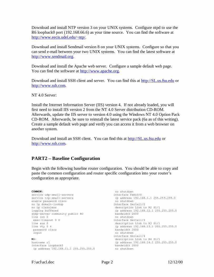
F:\acl\acl.doc Page 2 12/12/00
Download and install NTP version 3 on your UNIX systems. Configure ntpd to use the R6 loopback0 port (192.168.66.6) as your time source. You can find the software at http://www.eecis.udel.edu/~ntp/. Download and install Sendmail version 8 on your UNIX systems. Configure so that you can send e-mail between your two UNIX systems. You can find the latest software at http://www.sendmail.org. Download and install the Apache web server. Configure a sample default web page. You can find the software at http://www.apache.org. Download and install SSH client and server. You can find this at http://SL.us.fsu.edu or http://www.ssh.com. NT 4.0 Server: Install the Internet Information Server (IIS) version 4. If not already loaded, you will first need to install IIS version 2 from the NT 4.0 Server distribution CD-ROM. Afterwards, update the IIS server to version 4.0 using the Windows NT 4.0 Option Pack CD-ROM. Afterwards, be sure to reinstall the latest service pack (6a as of this writing). Create a sample default web page and verify you can access it from a web browser on another system. Download and install an SSH client. You can find this at http://SL.us.fsu.edu or http://www.ssh.com. PART2 – Baseline Configuration Begin with the following baseline router configuration. You should be able to copy and paste the common configuration and router specific configuration into your router’s configuration as appropriate. COMMON: service udp-small-servers service tcp-small-servers enable password cisco no ip domain-lookup no ip classless logging buffered snmp-server community public RO line con 0 exec-timeout 0 0 line aux 0 line vty 0 4 password cisco login R1: hostname r1 interface Loopback0 ip address 192.168.11.1 255.255.255.0
no shutdown interface Fddi0/0 ip address 192.168.1.1 255.255.255.0 no shutdown interface Serial1/2 description Link to R2 S1/1 ip address 192.168.12.1 255.255.255.0 bandwidth 2000 no shutdown interface Serial1/3 description Link to R3 S1/1 ip address 192.168.13.1 255.255.255.0 bandwidth 2000 no shutdown interface Serial1/4 description Link to R4 S1/1 ip address 192.168.14.1 255.255.255.0 bandwidth 2000 no shutdown
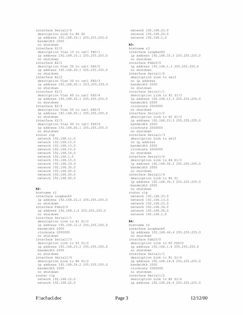
F:\acl\acl.doc Page 3 12/12/00
interface Serial1/6 description Link to R6 S0 ip address 192.168.16.1 255.255.255.0 bandwidth 2000 no shutdown interface E2/0 description Vlan 10 to cat1 FA0/1 ip address 192.168.10.1 255.255.255.0 no shutdown interface E2/1 description Vlan 20 to cat1 FA0/2 ip address 192.168.20.1 255.255.255.0 no shutdown interface E2/2 description Vlan 30 to cat1 FA0/3 ip address 192.168.30.1 255.255.255.0 no shutdown interface E2/3 description Vlan 40 to cat1 FA0/4 ip address 192.168.40.1 255.255.255.0 no shutdown interface E2/4 description Vlan 50 to cat1 FA0/5 ip address 192.168.50.1 255.255.255.0 no shutdown interface E2/5 description Vlan 60 to cat1 FA0/6 ip address 192.168.60.1 255.255.255.0 no shutdown router rip network 192.168.11.0 network 192.168.12.0 network 192.168.13.0 network 192.168.14.0 network 192.168.16.0 network 192.168.1.0 network 192.168.10.0 network 192.168.20.0 network 192.168.30.0 network 192.168.40.0 network 192.168.50.0 network 192.168.60.0 R2: hostname r2 interface Loopback0 ip address 192.168.22.2 255.255.255.0 no shutdown interface Fddi0/0 ip address 192.168.1.2 255.255.255.0 no shutdown interface Serial1/1 description Link to R1 S1/2 ip address 192.168.12.2 255.255.255.0 bandwidth 2000 clockrate 2000000 no shutdown interface Serial1/3 description Link to R3 S1/2 ip address 192.168.23.2 255.255.255.0 bandwidth 2000 no shutdown interface Serial1/4 description Link to R4 S1/2 ip address 192.168.24.2 255.255.255.0 bandwidth 2000 no shutdown router rip network 192.168.12.0 network 192.168.22.0
network 192.168.23.0 network 192.168.24.0 network 192.168.1.0 R3: hostname r3 interface Loopback0 ip address 192.168.33.3 255.255.255.0 no shutdown interface Fddi0/0 ip address 192.168.1.3 255.255.255.0 no shutdown interface Serial1/0 description Link to self no ip address bandwidth 2000 no shutdown interface Serial1/1 description Link to R1 S1/3 ip address 192.168.13.3 255.255.255.0 bandwidth 2000 clockrate 2000000 no shutdown interface Serial1/2 description Link to R2 S1/3 ip address 192.168.23.3 255.255.255.0 bandwidth 2000 clockrate 2000000 no shutdown interface Serial1/3 description Link to self no ip address bandwidth 2000 clockrate 2000000 no shutdown interface Serial1/4 description Link to R4 S1/3 ip address 192.168.34.3 255.255.255.0 bandwidth 2000 no shutdown interface Serial1/6 description Link to R6 S1 ip address 192.168.36.3 255.255.255.0 bandwidth 2000 no shutdown router rip network 192.168.33.0 network 192.168.13.0 network 192.168.23.0 network 192.168.34.0 network 192.168.36.0 network 192.168.1.0 R4: hostname r4 interface Loopback0 ip address 192.168.44.4 255.255.255.0 no shutdown interface Fddi0/0 description Link to R5 FDDI0 ip address 192.168.1.4 255.255.255.0 no shutdown interface Serial1/1 description Link to R1 S1/4 ip address 192.168.14.4 255.255.255.0 bandwidth 2000 clockrate 2000000 no shutdown interface Serial1/2 description Link to R2 S1/4 ip address 192.168.24.4 255.255.255.0
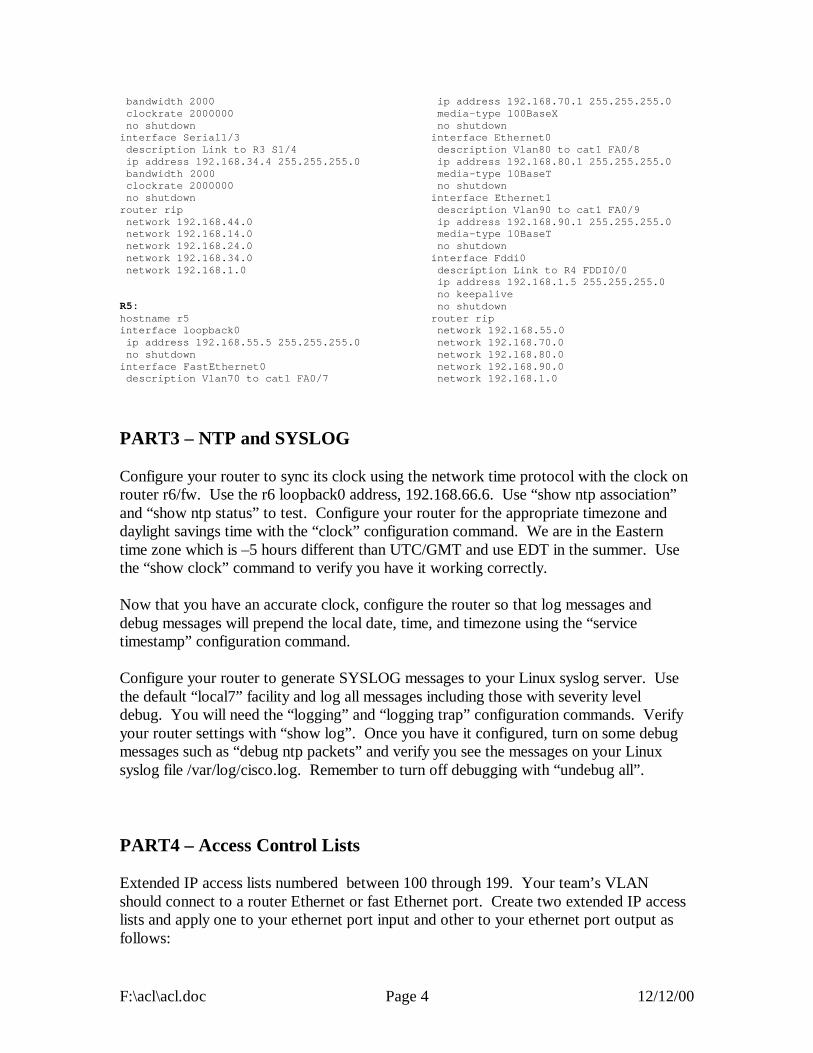
F:\acl\acl.doc Page 4 12/12/00
bandwidth 2000 clockrate 2000000 no shutdown interface Serial1/3 description Link to R3 S1/4 ip address 192.168.34.4 255.255.255.0 bandwidth 2000 clockrate 2000000 no shutdown router rip network 192.168.44.0 network 192.168.14.0 network 192.168.24.0 network 192.168.34.0 network 192.168.1.0 R5: hostname r5 interface loopback0 ip address 192.168.55.5 255.255.255.0 no shutdown interface FastEthernet0 description Vlan70 to cat1 FA0/7
ip address 192.168.70.1 255.255.255.0 media-type 100BaseX no shutdown interface Ethernet0 description Vlan80 to cat1 FA0/8 ip address 192.168.80.1 255.255.255.0 media-type 10BaseT no shutdown interface Ethernet1 description Vlan90 to cat1 FA0/9 ip address 192.168.90.1 255.255.255.0 media-type 10BaseT no shutdown interface Fddi0 description Link to R4 FDDI0/0 ip address 192.168.1.5 255.255.255.0 no keepalive no shutdown router rip network 192.168.55.0 network 192.168.70.0 network 192.168.80.0 network 192.168.90.0 network 192.168.1.0
PART3 – NTP and SYSLOG Configure your router to sync its clock using the network time protocol with the clock on router r6/fw. Use the r6 loopback0 address, 192.168.66.6. Use “show ntp association” and “show ntp status” to test. Configure your router for the appropriate timezone and daylight savings time with the “clock” configuration command. We are in the Eastern time zone which is –5 hours different than UTC/GMT and use EDT in the summer. Use the “show clock” command to verify you have it working correctly. Now that you have an accurate clock, configure the router so that log messages and debug messages will prepend the local date, time, and timezone using the “service timestamp” configuration command. Configure your router to generate SYSLOG messages to your Linux syslog server. Use the default “local7” facility and log all messages including those with severity level debug. You will need the “logging” and “logging trap” configuration commands. Verify your router settings with “show log”. Once you have it configured, turn on some debug messages such as “debug ntp packets” and verify you see the messages on your Linux syslog file /var/log/cisco.log. Remember to turn off debugging with “undebug all”.
PART4 – Access Control Lists Extended IP access lists numbered between 100 through 199. Your team’s VLAN should connect to a router Ethernet or fast Ethernet port. Create two extended IP access lists and apply one to your ethernet port input and other to your ethernet port output as follows:

F:\acl\acl.doc Page 5 12/12/00
interface [ethernetX|fastethernetX] ip access-group XXX in ip access-group YYY out
Where XXX = (100 + 10 x TEAM) and YYY = (101 + 10 x TEAM):
TEAM INPUT ACL OUTPUT ACL 1 110 111 2 120 121 3 130 131 4 140 141 5 150 151 6 160 161 7 170 171 8 180 181 9 190 191
(The terms Input and Output are relative to your router’s ethernet port. The terms “host” and “server” are synonymous in this context.) Create two IP extended access lists for the input and output of your gateway router’s ethernet interface to your team VLAN and apply to your ethernet or fast ethernet port with the following security policy: Security Policy:
- Hosts on your VLAN should generally be able to access services outside your
VLAN provided the services are not outside the FSU network. (FSU networks 128.186.0.0/16, 146.201.0.0/16, and 144.174.0.0/16 and RFC1918 private address space 192.168.0.0/16, 172.16.0.0/12, and 10.0.0.0/8 should be permitted).
- Do not allow any spoofed packets into your VLAN. - Allow all NETBIOS over TCP/IP traffic. - Allow all DNS, NTP, TFTP, SNMP, SYSLOG, and RIP v1 datagrams. (Do
not worry about SNMP traps or DNS zone transfers). - Allow TCP DISCARD and TTCP/IPERF packets for testing. - Allow all ICMP packets for testing. - Allow all shell (ssh), and web (www/http) access to hosts on your VLAN (Do
not worry about secure http). - Allow e-mail access (smtp,pop3,imap) to only your Linux server. - Allow TELNET access to your servers if sourced from a trusted group’s
VLAN. All even groups only trust each other. All odd groups only trust each other.
- Disallow any other TELNET access from unauthorized IP addresses - Deny everything else.

F:\acl\acl.doc Page 6 12/12/00
- All disallowed traffic must be logged to your Linux host using syslog on file /var/log/cisco.log
You can find out TCP/IP port number assignments from the Internet Assigned Numbers Authority, http://www.isi.edu/in-notes/iana/assignments/port-numbers. The relevant assignments are also included in the table below. service protocol port description discard tcp 9 Bit Bucket/Discard Protocol for Testing ssh tcp 22 SSH Remote Login Protocol telnet tcp 23 Telnet smtp tcp 25 Simple Mail Transfer Protocol dns udp 53 Domain Name Server tftp udp 69 Trivial File Transfer Protocol http/www tcp 80 HyperText Transport Protocol (WWW) pop3 tcp 110 Post Office Protocol version 3 ntp udp 123 Network Time Protocol netbios-ns tcp 137 NETBIOS Name Service netbios-ns udp 137 NETBIOS Name Service netbios-dgm tcp 138 NETBIOS Datagram Service netbios-dgm udp 138 NETBIOS Datagram Service netbios-ssn tcp 139 NETBIOS Session Service netbios-ssn udp 139 NETBIOS Session Service imap4 tcp 143 Internet Message Access Protocol snmp udp 161 Simple Network Management Protocol syslog udp 514 System Log Messages rip udp 520 Routing Information Protocol ttcp/iperf tcp 5001 Test TCP / IPERF Testing Protocol Example of how to apply an access list to an ethernet interface and converting the policy into a detailed intermediate form before coding the access lists: interface ethernet0 ip address 192.168.10.1 255.255.255.0 ip access-group 110 in ip access-group 111 out Input access list 110:
1. Allow all traffic, provided the destination is in RFC1918 private address space or one of FSU’s three class B addresses: a. 192.168.0.0/16 b. 172.16.0.0/12 c. 10.0.0.0/8 d. 128.186.0.0/16
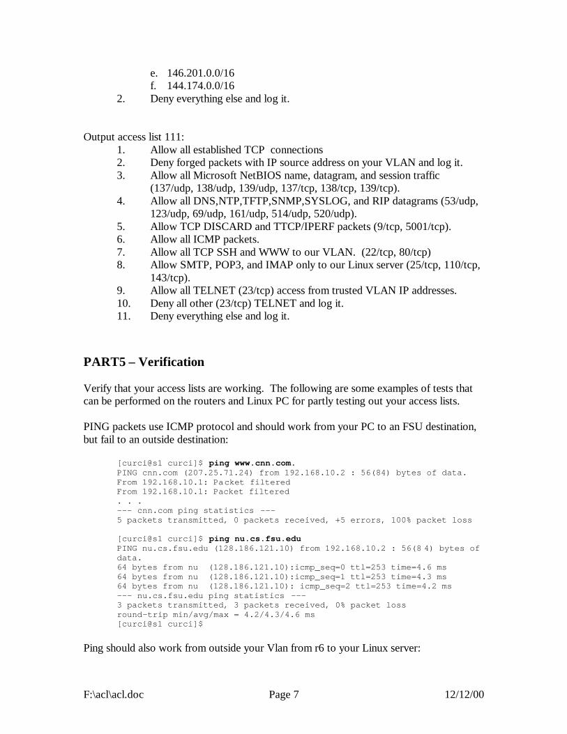
F:\acl\acl.doc Page 7 12/12/00
e. 146.201.0.0/16 f. 144.174.0.0/16
2. Deny everything else and log it. Output access list 111:
1. Allow all established TCP connections 2. Deny forged packets with IP source address on your VLAN and log it. 3. Allow all Microsoft NetBIOS name, datagram, and session traffic
(137/udp, 138/udp, 139/udp, 137/tcp, 138/tcp, 139/tcp). 4. Allow all DNS,NTP,TFTP,SNMP,SYSLOG, and RIP datagrams (53/udp,
123/udp, 69/udp, 161/udp, 514/udp, 520/udp). 5. Allow TCP DISCARD and TTCP/IPERF packets (9/tcp, 5001/tcp). 6. Allow all ICMP packets. 7. Allow all TCP SSH and WWW to our VLAN. (22/tcp, 80/tcp) 8. Allow SMTP, POP3, and IMAP only to our Linux server (25/tcp, 110/tcp,
143/tcp). 9. Allow all TELNET (23/tcp) access from trusted VLAN IP addresses. 10. Deny all other (23/tcp) TELNET and log it. 11. Deny everything else and log it.
PART5 – Verification Verify that your access lists are working. The following are some examples of tests that can be performed on the routers and Linux PC for partly testing out your access lists. PING packets use ICMP protocol and should work from your PC to an FSU destination, but fail to an outside destination:
[curci@s1 curci]$ ping www.cnn.com. PING cnn.com (207.25.71.24) from 192.168.10.2 : 56(84) bytes of data. From 192.168.10.1: Packet filtered From 192.168.10.1: Packet filtered . . . --- cnn.com ping statistics --- 5 packets transmitted, 0 packets received, +5 errors, 100% packet loss [curci@s1 curci]$ ping nu.cs.fsu.edu PING nu.cs.fsu.edu (128.186.121.10) from 192.168.10.2 : 56(8 4) bytes of data. 64 bytes from nu (128.186.121.10):icmp_seq=0 ttl=253 time=4.6 ms 64 bytes from nu (128.186.121.10):icmp_seq=1 ttl=253 time=4.3 ms 64 bytes from nu (128.186.121.10): icmp_seq=2 ttl=253 time=4.2 ms --- nu.cs.fsu.edu ping statistics --- 3 packets transmitted, 3 packets received, 0% packet loss round-trip min/avg/max = 4.2/4.3/4.6 ms [curci@s1 curci]$
Ping should also work from outside your Vlan from r6 to your Linux server:

F:\acl\acl.doc Page 8 12/12/00
fw/r6#ping 192.168.10.2 Type escape sequence to abort. Sending 5, 100-byte ICMP Echos to 192.168.10.2, timeout is 2 seconds: !!!!! Success rate is 100 percent (5/5), round -trip min/avg/max = 4/7/12 ms fw/r6#
Test NTP protocol by syncing Linux server clock to ntp server on r6 loopback address 192.168.66.6 using the ntpdate utility:
[root@s1 curci]# /usr/sbin/ntpdate -v 192.168.66.6 22 Nov 23:23:33 ntpdate[1826]: ntpdate 3 -5.93e Fri Feb 18 18:55:19 EST 2000 (1) 22 Nov 23:23:33 ntpdate[1826]: adjust time server 192.168.66.6 offset 0.001193 sec
Test SNMP protocol by fetching the system.sysName.0 MIB variable from r6:
[root@s1 curci]# snmpget -v 1 192.168.66.6 public system.sysName.0 system.sysName.0 = fw/r6
Test DNS datagram traffic by fetching the SOA record for domain cs.fsu.edu from nu.cs.fsu.edu:
[root@s1 curci]# nslookup > lserver nu.cs.fsu.edu. Default Server: nu.cs.fsu.edu Address: 128.186.121.10 > set type=SOA > cs.fsu.edu. fsu.edu origin = dns1.fsu.edu mail addr = hostmaster.acns.fsu.edu serial = 2000112203 refresh = 3600 (1H) retry = 1200 (20M) expire = 604800 (1W) minimum ttl = 86400 (1D) >
From Linux PC, test iperf client using discard TCP port 9 on r6:
[root@s1 curci]# iperf -c 192.168.66.6 -p 9 ------------------------------------------------------------ Client connecting to 192.168.66.6, TCP port 9 TCP window size: 64.0 KByte (default) ------------------------------------------------------------ [ 3] local 192.168.10.2 port 2690 connected with 192.168.66.6 port 9 [ ID] Interval Transfer Bandwidth [ 3] 0.0-10.3 sec 1.5 MBytes 1.1 Mbits/sec [root@s1 curci]#
From the Linux PC, test access to an outside FSU web page http://www.cs.fsu.edu/~curci:

F:\acl\acl.doc Page 9 12/12/00
[root@s1 curci]# telnet www.cs.fsu.edu 80 Trying 128.186.121.41... Connected to xi.cs.fsu.edu. Escape character is '^]'. GET /~curci/ <html> <head><title>Ray Curci Home Page</title></head> <body>Ray Curci Home Page 16-Nov-2000</p> I am presently working on an MS degree in the FSU Computer Network and Systems Administration track. </body></html> Connection closed by foreign host. [root@s1 curci]#
Your team VLAN should connect to an ethernet port on either r1 or r5. If you go to r1 or r5, whichever does not connect to your VLAN, you can execute TELNET sourced from a trusted and untrusted group to verify the access list. For example, I am on team 1 served from router r1 interface ethernet 2/0, and my Linux server is at IP address 192.168.10.2. (Vlan10). If try to telnet to my Linux PC from r5 and source from team 8’s untrusted ethernet port Ethernet0 it should fail, but work if sourced from team 9’s trusted ethernet port Ethernet1, it should work and I will see the login prompt:
(Sourced from r5 Ethernet0, ip address 19 2.168.80.1 (untrusted)) r5#telnet 192.168.10.2 /source-interface Ethernet0 Trying 192.168.10.2 ... % Destination unreachable; gateway or host down (Sourced from r5 Ethernet1, ip address 192.168.90.1 (trusted)) r5#telnet 192.168.10.2 /source-interface Ethernet1 Trying 192.168.10.2 ... Open Red Hat Linux release 6.2 (Zoot) Kernel 2.2.14-5.0 on an i586 login:
My my Linux syslog server in logfile /var/log/cisco.log, the denied telnet attempt from 192.168.80.1 appears. There are four fields in this message (1) time/date stamp prepended by the Linux syslogd program, (2) IP address of device that sent the message, r1’s ethernet 2/0 port, prepended by Linux syslogd, (3) time/date stamp prepended by router r1, and (4) the log message itself indicating a denied TCP packet from 192.168.80.1 port 11000 to 192.168.10.2 port 23 (telnet port):
Nov 22 23:43:54 192.168.10.1 63: Nov 22 23:43:53 EST: %SEC-6-IPACCESSLOGP: list 111 denied tcp 192.168.80.1(11000) -> 192.168.10.2(23), 1 packet
From outside, I should be able to access the WWW server on my Linux system (192.168.10.2) or NT system at 192.168.10.3:
fw/r6#telnet 192.168.10.2 80 Trying 192.168.10.2, 80 ... Open GET / <html><head><title>S1 Sample WWW Page</title></head><body>
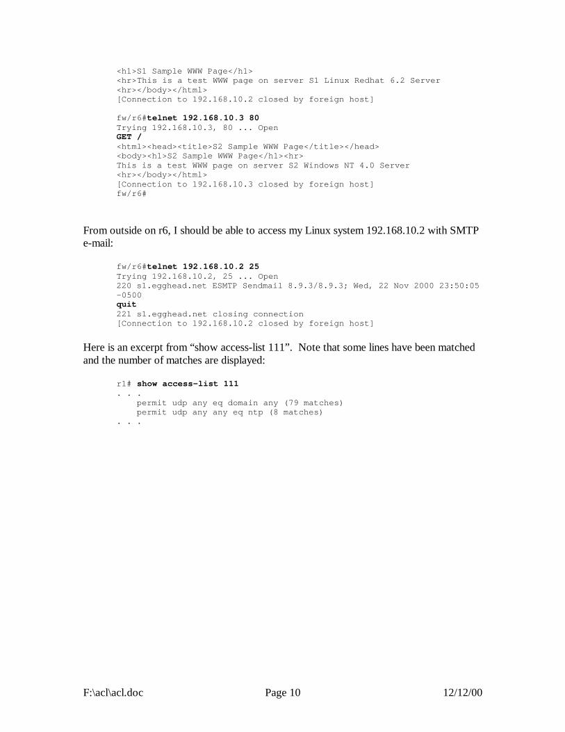
F:\acl\acl.doc Page 10 12/12/00
<h1>S1 Sample WWW Page</h1> <hr>This is a test WWW page on server S1 Linux Redhat 6.2 Server <hr></body></html> [Connection to 192.168.10.2 closed by foreign host] fw/r6#telnet 192.168.10.3 80 Trying 192.168.10.3, 80 ... Open GET / <html><head><title>S2 Sample WWW Page</title></head> <body><h1>S2 Sample WWW Page</h1><hr> This is a test WWW page on server S2 Windows NT 4.0 Server <hr></body></html> [Connection to 192.168.10.3 closed by foreign host] fw/r6#
From outside on r6, I should be able to access my Linux system 192.168.10.2 with SMTP e-mail:
fw/r6#telnet 192.168.10.2 25 Trying 192.168.10.2, 25 ... Open 220 s1.egghead.net ESMTP Sendmail 8.9.3/8.9.3; Wed, 22 Nov 2000 23:50:05 -0500 quit 221 s1.egghead.net closing connection [Connection to 192.168.10.2 closed by foreign host]
Here is an excerpt from “show access-list 111”. Note that some lines have been matched and the number of matches are displayed:
r1# show access-list 111 . . . permit udp any eq domain any (79 matches) permit udp any any eq ntp (8 matches) . . .

VLA
N90
VLA
N80
VLA
N70
VLA
N60
VLA
N50
VLA
N40
VLA
N30
VLA
N20
128.186.121 .0/24
100MbpsFDDI Ring
VLA
N10
R5 (4500)
R2 (7000)
R1 (7000)
R4 (7000)
2Mbps
2Mbps
R3 (7000)
S1/3S1/3DCE
S1/6
S1/1DCE
E2/0 E1
FDDI0
acl.vsd 20-Nov-2000 R .Curci
FW/R6 (2511)
COMP SCINETWORK
S1DCE
E2/5 E0FA0
ACL LAB
2Mbp
s
S1/2
2Mbps
L0
L0
L0
L0
FDDI0/0
FDDI0/0
FDDI0/0
FDDI0/0
S1/4
S1/2DCE
S1/2 DCE
S1/4
L0
2Mbps
2Mbp
s
2Mbps
2Mbps
S0DCE
S1/4
S1/3
S1/6
S1/1 DCE
S1/1DCE
Linux
NT
Solaris
TEAM 1
interface E2/0 ip add 192.168.10.1255.255.255.0 ip access-group 110 in ip access-group 111 out
interface E1 ip add 192.168.90.1255.255.255.0 ip access-group 190 in ip access-group 191 out
NAT
L0
NTP TIME SOURCE
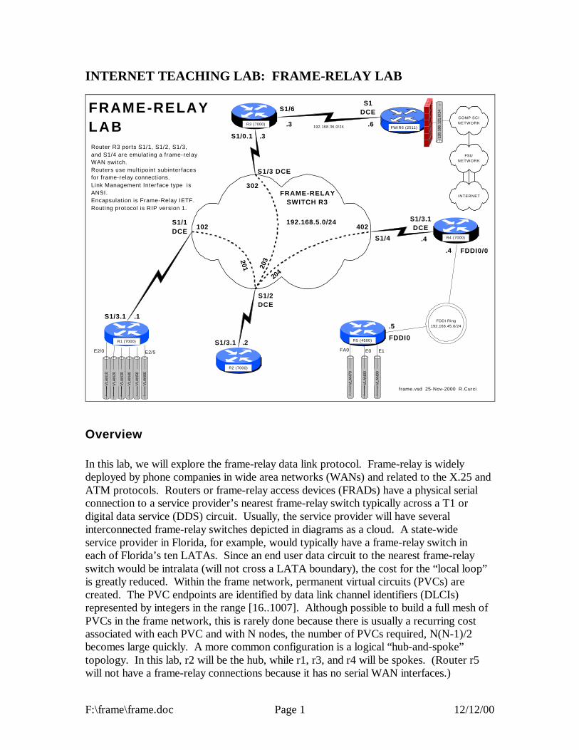
F:\frame\frame.doc Page 1 12/12/00
INTERNET TEACHING LAB: FRAME-RELAY LAB
FDDI Ring192.168.45.0/24
VLA
N90
VLA
N80
VLA
N70
VLA
N60
VLA
N50
VLA
N40
VLA
N30
VLA
N20
128.
186.
121.
0/24
VLA
N10
R5 (4500)
R2 (7000)
R1 (7000)
R4 (7000)
R3 (7000)
E2/0 E1
FDDI0
frame.vsd 25-Nov-2000 R.Curci
FW/R6 (2511)
COMP SCINETWORK
E2/5 E0FA0
FRAME-RELAYLAB
S1/3.1
192.168.36.0/24
FRAME-RELAYSWITCH R3
FDDI0/0
204
402
302
203
102
201
S1/3 DCE
S1/4
S1/2DCE
S1/1DCE
S1/3.1
S1/3.1DCE
S1/0.1
S1DCE
.6
S1/6
.3
192.168.5.0/24
.5
.4
Router R3 ports S1/1, S1/2, S1/3,and S1/4 are emulating a frame-relayWAN switch.Routers use multipoint subinterfacesfor frame-relay connections.Link Management Interface type isANSI.Encapsulation is Frame-Relay IETF.Routing protocol is RIP version 1.
.3
.1
.2
.4
FSUNETWORK
INTERNET
Overview In this lab, we will explore the frame-relay data link protocol. Frame-relay is widely deployed by phone companies in wide area networks (WANs) and related to the X.25 and ATM protocols. Routers or frame-relay access devices (FRADs) have a physical serial connection to a service provider’s nearest frame-relay switch typically across a T1 or digital data service (DDS) circuit. Usually, the service provider will have several interconnected frame-relay switches depicted in diagrams as a cloud. A state-wide service provider in Florida, for example, would typically have a frame-relay switch in each of Florida’s ten LATAs. Since an end user data circuit to the nearest frame-relay switch would be intralata (will not cross a LATA boundary), the cost for the “local loop” is greatly reduced. Within the frame network, permanent virtual circuits (PVCs) are created. The PVC endpoints are identified by data link channel identifiers (DLCIs) represented by integers in the range [16..1007]. Although possible to build a full mesh of PVCs in the frame network, this is rarely done because there is usually a recurring cost associated with each PVC and with N nodes, the number of PVCs required, N(N-1)/2 becomes large quickly. A more common configuration is a logical “hub-and-spoke” topology. In this lab, r2 will be the hub, while r1, r3, and r4 will be spokes. (Router r5 will not have a frame-relay connections because it has no serial WAN interfaces.)

F:\frame\frame.doc Page 2 12/12/00
Frame-relay switches also use a control protocol called the link management interface (LMI) used to inform routers what DLCIs are defined and their status. ASSIGNMENT: In this lab, you will be given a partially broken router configuration with 3 problems that need to be identified and solved:
1. The frame-relay DLCIs by default are associated with the router physical interfaces but in this exercise need to be associated with the subinterfaces. For example, on r4, the DLCI 402 should be associated with the multipoint subinterface Serial1/3.1 instead of physical interface Serial1/3.
2. Routers r1, r2, r3, and r4 all have their frame-relay interfaces addressed on the same 192.168.5.0/24 network, yet only some will be able to PING each other. A protocol called “inverse arp” can automatically map frame-relay DLCI numbers to IP addresses, but the mapping will be incomplete because there is not a full mesh of PVCs. You will find that R2 can PING the R1, R3, and R4 and they can PING R2, but that R1, R3, and R4 cannot PING each other.
3. Distance vector routing protocols like RIP normally do not advertise routes out an interface on which the route was learned. This behavior is called “split horizon”.
Commands that may be helpful to debug this assignment:
- show frame-relay pvc - show frame-relay lmi - debug frame-relay events - debug frame-relay packets - show ip route - show ip protocol - show ip interface - show frame-relay route (useful only on R2)
Hints: Read up on the following commands in the Cisco manuals:
- frame-relay interface-dlci - frame-relay map ip - ip split-horizon

F:\frame\frame.doc Page 3 12/12/00
Even with the partially broken configuration given, you should see LMI or Link Management Interface messages on your router. These are status messages where the frame-relay switch informs your router which DLCIs are defined and their status. You can use the “show frame-relay lmi” command. If set up correctly, you should see the number of status enquire messages sent incrementing, with an equal number of status messages received as shown below. Good Luck!
r4#show frame-relay lmi LMI Statistics for interface Serial1/3 (Frame Relay DTE) LMI TYPE = ANSI Invalid Unnumbered info 0 Invalid Prot Disc 0 Invalid dummy Call Ref 0 Invalid Msg Type 0 Invalid Status Message 0 Invalid Lock Shift 0 Invalid Information ID 0 Invalid Report IE Len 0 Invalid Report Request 0 Invalid Keep IE Len 0 Num Status Enq. Sent 94818 Num Status msgs Rcvd 94818 Num Update Status Rcvd 0 Num Status Timeouts 0
r Router Interface IP Address r1 Loopback0 192.168.11.1/24 ethernet2/0 192.168.10.1/24 ethernet2/1 192.168.20.1/24 ethernet2/2 192.168.30.1/24 ethernet2/3 192.168.40.1/24 ethernet2/4 192.168.50.1/24 ethernet2/5 192.168.60.1/24 serial1/3.1 192.168.5.1/24 r2 Loopback0 192.168.22.2/24 serial1/3.1 192.168.5.2/24 r3 Loopback0 192.168.33.3/24 serial1/0.1 192.168.5.3/24 serial1/6 192.168.36.3/24 r4 Loopback0 192.168.44.4/24 fddi0/0 192.168.45.4/24 serial1/3.1 192.168.5.4/24 r5 Loopback0 192.168.55.5/24 fastethernet0 192.168.70.1/24 ethernet0 192.168.80.1/24 ethernet1 192.168.90.1/24 fddi0 192.168.45.5/24

F:\frame\frame.doc Page 4 12/12/00
BROKEN ROUTER CONFIGURATION: COMMON: service udp-small-servers service tcp-small-servers enable password cisco no ip domain-lookup ip classless ip subnet-zero logging buffered service timestamps debug datetime localtime service timestamps log datetime localtime clock timezone EST -5 clock summer-time EDT recurring ntp server 192.168.66.6 snmp-server community public RO line con 0 exec-timeout 0 0 line aux 0 line vty 0 4 password cisco login R1: hostname r1 interface E2/0 description Vlan 10 to cat1 FA0/1 ip address 192.168.10.1 255.255.255 .0 no shutdown interface E2/1 description Vlan 20 to cat1 FA0/2 ip address 192.168.20.1 255.255.255.0 no shutdown interface E2/2 description Vlan 30 to cat1 FA0/3 ip address 192.168.30.1 255.255.255.0 no shutdown interface E2/3 description Vlan 40 to cat1 FA0/4 ip address 192.168.40.1 255.255.255.0 no shutdown interface E2/4 description Vlan 50 to cat1 FA0/5 ip address 192.168.50.1 255.255.255.0 no shutdown interface E2/5 description Vlan 60 to cat1 FA0/6 ip address 192.168.60.1 255.255.255.0 no shutdown interface loopback0 ip address 192.168.11.1 255.255.255.0 no shutdown interface Serial1/3 description Frame-Relay WAN encapsulation frame-relay IETF frame-relay lmi-type ansi no shutdown interface Serial1/3.1 multipoint ip address 192.168.5.1 255.255.255.0 no shutdown router rip network 192.168.11.0 network 192.168.10.0 network 192.168.20.0 network 192.168.30.0 network 192.168.40.0 network 192.168.50.0 network 192.168.60.0 network 192.168.5.0
R2: hostname r2 interface loopback0 ip address 192.168.22.2 255.255.255.0 no shutdown interface Serial1/3 description Frame-Relay WAN encapsulation frame-relay IETF frame-relay lmi-type ansi no shutdown interface Serial1/3.1 multipoint ip address 192.168.5.2 255.255.255.0 no shutdown router rip network 192.168.22.0 network 192.168.5.0 R3: hostname r3 frame-relay switching interface loopback0 ip address 192.168.33.3 255.255.255.0 no shutdown interface Serial1/0 description Frame-Relay WAN encapsulation frame-relay IETF frame-relay lmi-type ansi no shutdown interface Serial1/0.1 multipoint ip address 192.168.5.3 255.255.255.0 no shutdown interface Serial1/1 description Frame-Relay port to R1 S1/3 no ip address encapsulation frame-relay IETF clockrate 2000000 frame-relay lmi-type ansi frame-relay intf-type dce frame-relay route 102 interface Serial1/2 201 no shutdown interface Serial1/2 description Frame-Relay port to R2 S1/3 no ip address encapsulation frame-relay IETF clockrate 2000000 frame-relay lmi-type ansi frame-relay intf-type dce frame-relay route 201 interface Serial1/1 102 frame-relay route 203 interface Serial1/3 302 frame-relay route 204 interface Serial1/4 402 no shutdown interface Serial1/3 description Frame-Relay port to R3 S1/0 no ip address encapsulation frame-relay IETF clockrate 2000000 frame-relay lmi-type ansi frame-relay intf-type dce frame-relay route 302 interface Serial1/2 203 no shutdown interface Serial1/4 description Frame-Relay port to R4 S1/3

F:\frame\frame.doc Page 5 12/12/00
no ip address encapsulation frame-relay IETF frame-relay lmi-type ansi frame-relay intf-type dce frame-relay route 402 interface Serial1/2 204 no shutdown ! interface serial1/6 descr Serial link to R6 S1 toward Internet ip address 192.168.36.3 255.255.255.0 no shutdown router rip network 192.168.36.0 network 192.168.33.0 network 192.168.5.0 R4: hostname r4 interface loopback0 ip address 192.168.44.4 255.255.255.0 no shutdown interface fddi0/0 descr Link to R5 FDDI0 ip address 192.168.45.4 255.255.255.0 no shutdown interface Serial1/3 description Frame-Relay WAN encapsulation frame-relay IETF frame-relay lmi-type ansi clock rate 2000000 no shutdown interface Serial1/3.1 multipoint ip address 192.168.5.4 255.255.255.0 no shutdown
router rip network 192.168.44.0 network 192.168.45.0 network 192.168.5.0 R5: hostname r5 interface FastEthernet0 description Vlan70 to cat1 FA0/7 ip address 192.168.70.1 255.255.255.0 media-type 100BaseX no shutdown interface Ethernet0 description Vlan80 to cat1 FA0/8 ip address 192.168.80.1 255.255.255.0 media-type 10BaseT no shutdown interface Ethernet1 description Vlan90 to cat1 FA0/9 ip address 192.168.90.1 255.255.255.0 media-type 10BaseT no shutdown interface Fddi0 description Link to R4 FDDI0/0 ip address 192.168.45.5 255.255.255.0 no shutdown interface loopback0 ip address 192.168.55.5 255.255.255.0 no shutdown router rip network 192.168.70.0 network 192.168.80.0 network 192.168.90.0 network 192.168.45.0 network 192.168.55.0

FDDI Ring192.168.45 .0/24
VLA
N90
VLA
N80
VLA
N70
VLA
N60
VLA
N50
VLA
N40
VLA
N30
VLA
N20
128.
186.
121
.0/2
4
VLA
N10
R5 (4500)
R2 (7000)
R1 (7000)
R4 (7000)
R3 (7000)
E2/0 E1
FDDI0
frame.vsd 25-Nov-2000 R.Curci
FW/R6 (2511)
COMP SCINETWORK
E2/5 E0FA0
FRAME-RELAYLAB
S1/3.1
192.168.36 .0/24
FRAME-RELAYSWITCH R3
FDDI0/0
204
402
302
203
102
201
S1/3 DCE
S1/4
S1/2DCE
S1/1DCE
S1/3.1
S1/3.1DCE
S1/0.1
S1DCE
.6
S1/6
.3
192.168.5.0/24
.5
.4
Router R3 ports S1/1, S1/2, S1/3,and S1/4 are emulating a frame-relayWAN switch.Routers use multipoint subinte rfacesfor frame-relay connections.Link Management Interface type isANSI.Encapsulation is Frame-Rel ay IETF.Routing protocol is RIP version 1.
.3
.1
.2
.4
FSUNETWORK
INTERNET
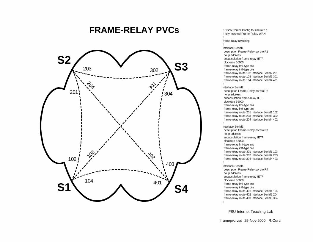
FSU Internet Teaching Lab
framepvc.vsd 25-Nov-2000 R.Curci
FRAME-RELAY PVCs
203
204
201
302
301
304
403402
401104
103
102
S2
S1 S4
S3
! Cisco Router Config to simulate a! fully meshed Frame-Relay WAN!frame-relay switching!interface Serial1 description Frame-Relay port to R1 no ip address encapsulation frame-relay IETF clockrate 56000 frame-relay lmi-type ansi frame-relay intf-type dce frame-relay route 102 interface Serial2 201 frame-relay route 103 interface Serial3 301 frame-relay route 104 interface Serial4 401!interface Serial2 description Frame-Relay port to R2 no ip address encapsulation frame-relay IETF clockrate 56000 frame-relay lmi-type ansi frame-relay intf-type dce frame-relay route 201 interface Serial1 102 frame-relay route 203 interface Serial3 302 frame-relay route 204 interface Serial4 402!interface Serial3 description Frame-Relay port to R3 no ip address encapsulation frame-relay IETF clockrate 56000 frame-relay lmi-type ansi frame-relay intf-type dce frame-relay route 301 interface Serial1 103 frame-relay route 302 interface Serial2 203 frame-relay route 304 interface Serial4 403!interface Serial4 description Frame-Relay port to R4 no ip address encapsulation frame-relay IETF clockrate 56000 frame-relay lmi-type ansi frame-relay intf-type dce frame-relay route 401 interface Serial1 104 frame-relay route 402 interface Serial2 204 frame-relay route 403 interface Serial3 304!

F:\multi\multi.doc Page 1 12/12/00
INTERNET TEACHING LAB: MULTIPROTOCOL LAB
VLAN90VLAN80VLAN70VLAN50 VLAN60VLAN40VLAN30VLAN20VLAN10
128.
186.
121.
0/24
100MbpsFDDI Ring
R3 (7000)
R5 (4500)
R2 (7000)
R1 (7000)
R4 (7000)
2Mbps
2Mbps
2Mbp
s
S1/3
S1/2DCE
FDDI0
multi.vsd 03-Nov-2000 R.Curci
FW/R6 (2511)
COMP SCINETWORK
2Mbps
S1DCE
E2/5E0
FA0
NAT
?
MULTIPROTOCOLLAB
IP: 192.168.10.1/24
IPX
NE
T: 10A
PP
LE A
DD
R: 10.1
AP
PLE
ZON
E: A
nthropology
IP: 192.168.20.1/24
IPX
NE
T: 20A
PP
LE A
DD
R: 20.1
AP
PLE
ZON
E: B
iology
IP: 192.168.30.1/24
IPX
NE
T: 30A
PP
LE A
DD
R: 30.1
AP
PLE
ZON
E: C
ompS
ci
IP: 192.168.40.1/24
IPX
NE
T: 40A
PP
LE A
DD
R: 40.1
AP
PLE
ZON
E: D
ance
IP: 192.168.50.1/24
IPX
NE
T: 50A
PP
LE A
DD
R: 50.1
AP
PLE
ZON
E: E
conomics
IP: 192.168.60.1/24
IPX
NE
T: 60A
PP
LE A
DD
R: 60.1
AP
PLE
ZON
E: Finance
IP: 192.168.70.1/24
IPX
NE
T: 70A
PP
LE A
DD
R: 70.1
AP
PLE
ZON
E: G
eology
IP: 192.168.80.1/24
IPX
NE
T: 80A
PP
LE A
DD
R: 80.1
AP
PLE
ZON
E: H
istory
IP: 192.168.90.1/24
IPX
NE
T: 90A
PP
LE A
DD
R: 90.1
AP
PLE
ZON
E: Insurance
E1E2/0
2Mbps
2Mbps
IP: 192.168.45.5/24IPX NET: FDD1APPLE ADDR: 45.5APPLE ZONE: FDDI
IP: 192.168.45.4/24IPX NET: FDD1APPLE ADDR: 45.4APPLE ZONE: FDDI
FDDI0/0
IP: 192.168.55.5/24IPX NET: 55
IP: 192.168.14.1/24IPX NET: 14APPLE ADDR: 14.1APPLE ZONE: r1r4
IP: 192.168.14.4/24IPX NET: 14APPLE ADDR: 14.4APPLE ZONE: r1r4
IP: 192.168.23.2/24IPX NET: 23APPLE ADDR: 23.2APPLE ZONE: r2r3
IP: 192.168.34.4/24IPX NET: 34APPLE ADDR: 34.4APPLE ZONE: r3r4
IP: 192.168.36.6/24IP: 192.168.36.3/24
S1/6
IP: 192.168.33.3/24IPX NET: 33
IP: 192.168.66.6/24
IP: 192.168.12.2/24IPX NET: 12APPLE ADDR: 12.2APPLE ZONE: r1r2
IP: 192.168.11.1/24IPX NET: 11
IP: 192.168.12.1/24IPX NET: 12APPLE ADDR: 12.1APPLE ZONE: r1r2
IP: 192.168.22.2/24IPX NET: 22
S1/1 DCEIP: 192.168.13.1/24IPX NET: 13APPLE ADDR: 13.1APPLE ZONE: r1r3
IP: 192.168.13.3/24IPX NET: 13APPLE ADDR: 13.3APPLE ZONE: r1r3
S1/1DCE
S1/4
S1/3S1/2
S1/3DCE
S1/1DCE
IP: 192.168.23.3/24IPX NET: 23APPLE ADDR: 23.3APPLE ZONE: r2r3
IP: 192.168.34.3/24IPX NET: 34APPLE ADDR: 34.3APPLE ZONE: r3r4
S1/4
E2/1
E2/2
E2/3
E2/4
L0
L0
L0
L0
L0
L0
IP: 192.168.44.4/24IPX NET: 44
Overview This lab explores two popular non-IP protocols: Novell’s IPX and Apple’s Appletalk. IPX is a modified version of the Xerox XNS protocol adapted for use on Novell fileservers. Today, this protocol is also supported under Windows and Linux. Appletalk was designed for use on the Apple Macintosh computer and Apple LaserWriter printers. It is supported under Linux and partly supported under Windows NT. For example, Windows NT has support to act as a native IPX fileserver or a native Appletalk Fileserver (called AppleShare in Apple terminology). This allows IPX and Apple devices to access the server without the need for additional software. Part 1 – IPX IPX network addresses are composed of a 32-bit network address and a 48 bit host address. The syntax is often abbreviated N.H.H.H and written in hexadecimal. Addresses can be entered in the form “NNNNNNNN.HHHH.HHHH.HHHH” but leading zeros can be omitted. IPX routing is turned on with the global router command

F:\multi\multi.doc Page 2 12/12/00
“ipx routing HHHH.HHHH.HHHH” where HHHH.HHHH.HHHH is a host identifier for your router. If present, this address will be used on interfaces that do not have any MAC address like serial lines. If omitted, the router will make up an address or use one from an active ethernet port. Embed your router name in the address to make things like routing table listings a little easier to read. For example, if you are programming router r4, turn on ipx with the global command “ipx routing 4.4.4”. Once the IPX routing process is running on the router, you will need to add an IPX network address to each interface you want to speak IPX. Use the interface command “ipx network NNNNNNNN” in hexadecimal. Follow the diagram above carefully to add IPX routing. The Cisco routers have an IPX PING command that is helpful to verify connectivity.
r5#ping Protocol [ip]: ipx Target IPX address: 11.1.1.1 Repeat count [5]: Datagram size [100]: Timeout in seconds [2]: Verbose [n]: Type escape sequence to abort. Sending 5, 100-byte IPXcisco Echoes to 11.0001.0001.0001, timeout is 2 seconds: !!!!! Success rate is 100 percent (5/5), round -trip min/avg/max = 4/4/8 ms
Use the following commands to help with debugging your configuration.
- show ipx route - show ipx interface - show ipx interface brief - show ipx traffic - show ipx server - show ipx server detailed
Part 2 – Appletalk Appletalk Phase II addresses of a 16-bit network address and 8-bit host address. Host addresses 0, 254, and 255 are reserved, so you can only use host addresses 1 through 253 in your network. In order to provision networks supporting more than 253 hosts, you can specify a range of consecutive network addresses (called “cable-range” in Apple terminology), but it will not be necessary in this lab. Appletalk normally will dynamically select an unused host number, however, we will be specifying it manually so it will be easier to test the network with tools like PING. Appletalk also uses the concept of a “zone” to logically name the networks. A single zone name may belong to multiple network segments, and a single network segment may have multiple zones, but only a single default zone. Zone names can include whitespace and non alphanumeric characters and are case sensitive, so type them carefully.

F:\multi\multi.doc Page 3 12/12/00
Enable appletalk routing with global command “appletalk routing” which uses the RTMP routing protocol by default. To enable appletalk on an interface and assign a network address, enter the interface command “appletalk cable-range N-N N.H” where N is your network number and H is your host number. The cisco router also has a built-in appletalk PING command that can be used for testing as follows.
r5#ping Protocol [ip]: apple Target AppleTalk address: 10.1 Repeat count [5]: Datagram size [100]: Timeout in seconds [2]: Verbose [n]: Sweep range of sizes [n]: Type escape sequence to abort. Sending 5, 100-byte AppleTalk Echos to 10.1, timeout is 2 seconds: !!!!! Success rate is 100 percent (5/5), round-trip min/avg/max = 4/7/12 ms
The following commands may be helpful if debugging your configuration.
- show appletalk route - show appletalk zone - show appletalk interface - show appletalk interface brief - show appletalk adjacent-routers - show appletalk globals - show appletalk neighbors - show appletalk traffic

VLAN90VLAN80VLAN70VLAN50 VLAN60VLAN40VLAN30VLAN20VLAN10
128.
186.
121
.0/2
4
100MbpsFDDI Ring
R3 (7000)
R5 (4500)
R2 (7000)
R1 (7000)
R4 (7000)
2Mbps
2Mbps
2Mbp
s
S1/3
S1/2DCE
FDDI0
multi-layer3.vsd 03-Nov-2000 R.Curci
FW/R6 (2511)
COMP SCINETWORK
2Mbps
S1DCE
E2/5E0
FA0
NAT
?
MULTIPROTOCOLLAB
IP: 192.168.10.1/24
IPX
NE
T: 10A
PP
LE A
DD
R: 10.1
AP
PLE
ZON
E: A
nthropology
IP: 192.168.20.1/24
IPX
NE
T: 20A
PP
LE A
DD
R: 20.1
AP
PLE
ZON
E: B
iology
IP: 192.168.30.1/24
IPX
NE
T: 30A
PP
LE A
DD
R: 30.1
AP
PLE
ZON
E: C
om
pSci
IP: 192.168.40.1/24
IPX
NE
T: 40A
PP
LE A
DD
R: 40.1
AP
PLE
ZON
E: D
ance
IP: 192.168.50.1/24
IPX
NE
T: 50A
PP
LE A
DD
R: 50.1
AP
PLE
ZON
E: E
conom
ics
IP: 192.168.60.1/24
IPX
NE
T: 60A
PP
LE A
DD
R: 60.1
AP
PLE
ZON
E: Finance
IP: 192.168.70.1/24
IPX
NE
T: 70A
PP
LE A
DD
R: 70.1
AP
PLE
ZON
E: G
eology
IP: 192.168.80.1/24
IPX
NE
T: 80A
PP
LE A
DD
R: 80.1
AP
PLE
ZON
E: H
istory
IP: 192.168.90.1/24
IPX
NE
T: 90A
PP
LE A
DD
R: 90.1
AP
PLE
ZON
E: Insurance
E1E2/0
2Mbps
2Mbps
IP: 192.168.45.5/24IPX NET: FDD1APPLE ADDR: 45.5APPLE ZONE: FDDI
IP: 192.168.45.4/24IPX NET: FDD1APPLE ADDR: 45.4APPLE ZONE: FDDI
FDDI0/0
IP: 192.168.55.5/24IPX NET: 55
IP: 192.168.14.1/24IPX NET: 14APPLE ADDR: 14.1APPLE ZONE: r1r4
IP: 192.168.14.4/24IPX NET: 14APPLE ADDR: 14.4APPLE ZONE: r1r4
IP: 192.168.23.2/24IPX NET: 23APPLE ADDR: 23.2APPLE ZONE: r2r3
IP: 192.168.34.4/24IPX NET: 34APPLE ADDR: 34.4APPLE ZONE: r3r4
IP: 192.168.36.6/24IP: 192.168.36.3/24
S1/6
IP: 192.168.33.3/24IPX NET: 33 IP: 192.168.66.6/24
IP: 192.168.12.2/24IPX NET: 12APPLE ADDR: 12.2APPLE ZONE: r1r2
IP: 192.168.11.1/24IPX NET: 11
IP: 192.168.12.1/24IPX NET: 12APPLE ADDR: 12.1APPLE ZONE: r1r2
IP: 192.168.22.2/24IPX NET: 22
S1/1 DCEIP: 192.168.13.1/24IPX NET: 13APPLE ADDR: 13.1APPLE ZONE: r1r3
IP: 192.168.13.3/24IPX NET: 13APPLE ADDR: 13.3APPLE ZONE: r1r3
S1/1DCE
S1/4
S1/3S1/2
S1/3DCE
S1/1DCE
IP: 192.168.23.3/24IPX NET: 23APPLE ADDR: 23.3APPLE ZONE: r2r3
IP: 192.168.34.3/24IPX NET: 34APPLE ADDR: 34.3APPLE ZONE: r3r4
S1/4
E2/1
E2/2
E2/3
E2/4
L0
L0
L0
L0
L0
L0
IP: 192.168.44.4/24IPX NET: 44

F:\spantree\spantree.doc Page 1 12/12/00
INTERNET TEACHING LAB: SPANNING TREE PROTOCOL
100MbpsFDDI Ring
1 0 M b p s E T H E R N E T
1 0 M b p s E T H E R N E T 1 0 M b p s E T H E R N E T
R3 (7000)
R5 (4500)
R2 (7000)
R1 (7000) R4 (7000)
S1 S2
56Kbps
56Kbps
56K
bps
56Kbp
s
56KbpsS1/3
S1/1DCE
S1/2DCE
S1/3DCE
S1/4
S1/4
S1/2DCE
S1/1DCE
S1/2
E2/0
E2/1 E1
E0
FDDI0FDDI0/0
span- layer1.vsd 17-Oct-2000 R.Curc i
S1/3
Port Path Cost:56Kbps ----> 1000M/56K ----> 178572Mbps -----> 1000M/2M -----> 50010Mbps ----> 1000M/10M ----> 100100Mbps ---> 1000M/100M ---> 10
Overview The Spanning Tree Protocol, also known as the Djistrja’s Algorithm, is documented in the IEEE 802.1D standard. It is implemented in many current routers, bridges, and switches to provide a loop-free network topology. It is popular to build layer2 networks with redundant network connections to improve reliability, but the redundancy can lead to broadcast storms. Spanning Tree Protocol provides a mechanism for network devices to learn the network topology, elect a root bridge, and selectively block ports to form a loop-free spanning tree. We will explore some of the capabilities of this protocol, advantages, and limitations. The IEEE spanning tree protocol was first implemented in the DEC LAN Bridge 100 in the mid 1980s by Dr. Radia Perlman whose text book, Interconnections, now in the second edition, is the definitive reference. Configuration We will explore the Cisco Router implementation of 802.1D. Set up the physical cabling as specified in diagram above. The initial configuration for all five routers is listed at the end of this document also also on text file span-config.txt. Log into each of the five routers R1, R2, R3, R4, and R5, go into router configuration mode, and paste the

F:\spantree\spantree.doc Page 2 12/12/00
appropriate configuration commands. Verify that all appropriate interfaces are up and that everything is cabled to the correct routers and ports. Use the commands “show ip interface”, “show ip interface brief”, and “show cdp neighbors” for verification. Setup PCs Configure PCs S1 and S2 with IP addresses in the same IP network. Verify that you can PING between the two PCs. (Hint: If this does not work you can test the PCs by temporarily connecting them to the same physical Ethernet segment or by using a 10baseT Ethernet crossover cable. You may have difficulty if your router interface accidently has an IP address on one of the bridge interface in which case it may be routing IP protocol and bridging non-IP traffic. You can verify that the router is bridging IP traffic on the appropriate interfaces with the command “show interface crb”) Try sending a series of PINGs from S1 à S2 using both small 64-byte packets and large 1500-byte packets and note the average round-trip time. Repeat this test while S1 and S2 are temporarily directly connected. Compare the numbers and if substancially different, explain why. There are redundant connections in your network and we want to determine the physical path between S1 and S2 used by the PING packets. First, determine the Ethernet MAC addresses for the NIC cards in S1 and S2. (Hint: If two devices on the same IP network have recently communicated, you will find each other’s Ethernet MAC address inside their respective ARP caches which can be displayed with the command “arp –a”) Use the command “show bridge 1” on each router to display the bridge forwarding table and find the S1 and S2 entries. Record the forwarding path on your network diagram.
Bridge IDs and Port Path Cost Using the command “show span 1”, determine which router is the root bridge and indicate it on your network diagram. This implementation of 802.1D computes the port path cost by dividing 1,000,000,000 by the bandwidth of the port in bits/second. This gives us the following port costs for the connections in your network:
INTERFACE TYPE BANDWIDTH PORT PATH COST 56K SERIAL 56,000 bits/sec 17857 10M ETHERNET 10,000,000 bits/sec 100 FDDI 100,000,000 bits/sec 10
Given your diagram, knowledge of the root bridge, and above table, manually compute the spanning tree algorithm. For each bridge port, indicate the port state (F=forwarding,

F:\spantree\spantree.doc Page 3 12/12/00
B=blocking) as well as the port type (RP=root port, DP=designated port, NDP=non-designated port). Verify your calculations by comparing them with the output of the command “show spanning-tree 1” on each router. Bridge Protocol Data Units On one of your routers with a blocked bridge port, issue the command “show interface xxx” where xxx is the name of the blocked interface/port. Note the input and output packet counters. Are they incrementing? If so, why are they incrementing? Instead of doing the arithmetic, you may find it easier to “clear counters” to zero the counters before you start. The Cisco router has a number of debug modes used to diagnose network problems. Although sometimes dangerous to use on a production network, they are very good tools in a lab environment. The command “term monitor” will enable debug messages to be displayed on your router session and disabled with “term no monitor”. Try turning on the spanning tree topology change debug with “debug spanning tree” until you collect a few messages, then turn it off with “undebug all”. You should see some bridge protocol data unit packets represented in hexadecimal. You should be able to spot the MAC address of your root bridge embedded in the packet. Using the following table, decode the root bridge ID (priority and MAC address), sending bridge ID (priority and MAC address), root path cost, and timers.
FIELD OCTETS FUNCTION Protocol ID 2 future (always zero) Version 1 future (always zero) Type 1 BPDU Type (0=config BPDU) Flags 1 LSB (topolgy chg flash), MSB (Topology chg ACK) Root BID 8 Bridge ID of root (16bit priority + 48bit MAC) Root Path Cost 4 Cumulativ e cost to root bridge Sending BID 8 Bridge ID of sender (16bit priority + 48bit MAC) Port ID 2 Port ID that sent this BPDU Message Age 2 Age of root BPDU Max Age 2 Max age to save BPDU info (default = 20s) Hello Time 2 T ime between sending consecutiv e BPDUs (default = 2s) Forward Delay 2 T ime spent in listening and learning states in FSM (default = 15s)
Finite State Machine

F:\spantree\spantree.doc Page 4 12/12/00
LEARNING(build bridge
table)
span- fsm.vsd 17-Oct-2000 R.Curc i
DISABLED
LISTENING(bui ld active
topology)
BLOCKING(receiveBPDUs)
FORWARDING
4
44
5
52
2
23
2
KEY:1 . PORT ENABLED2 . PORT D ISABLED3 . P O R T S E L E C T E D A S R O O T O R D P4 . P O R T U N S E L E C T E D A S R O O T O R D P5 . F O R W A R D I N G T I M E R E X P I R E S
D E F A U L T T I M E R S :Hello Timer ---------- 2 secondsForward Delay ---- 15 secondsMax Age ------------ 20 seconds
SPANNING TREE PORTFINITE STATE MACHINE
1
Bridge ports can be in one of five states: disabled, blocking, listening, learning, and forwarding. See the diagram span-fsm.pdf to see what events cause transitions between different states. Log into one of your routers and identify a bridge interface in the forwarding state. Turn on spanning tree topology events debugging with “debug spanning events” and shut down the interface with “interface xyz” and “shutdown”. Wait a minute, then turn it back on with “no shutdown”. Note the state changes as it transitions from the disabled to the forwarding state including intermediate states. Record how much time was spent in each state. Turn off debugging with “undebug all”. TEST TCP Locate the program TTCP by searching the Internet. At the time of this writing, it was available for anonymous/ftp download at ftp://FTP.ARL.MIL/pub/ttcp. It is a TCP/IP benchmarking program. There are both C-language versions, usually named ttcp.c, and java implementations that work on Windows systems. You basically start this program on one system in receive mode, then start the other copy in transmit mode and supply the IP address of the receiver. The utility sends several blocks of data (you specify how many blocks and how many bytes per block) then displays statistics in Bytes/Second and Bits/Second on speed of the transfer. Use this tool to measure the network performance from S1 à S2 traversing your network. How many bits per second did you achieve? Study your network diagram paying particular attention to your router link speeds and

F:\spantree\spantree.doc Page 5 12/12/00
which interfaces are blocked. As packets traverse your network, your throughput is affected factors such as the speed of the links traversed, congestion, router CPU load and switching method, errors, etc. If you focus on the link speeds, is there a better (faster) path through your network that is not used? Determine which bridge should be made the root bridge in order to maximize the S1 à S2 throughput and change your configuration to make it so. Is there an optimal solution or more than one equally good solution? Repeat your S1 à S2 test and compare results with the first time. (Hint: The bridge with lowest bridge ID is elected the root. BIDs are 64-bit numbers by concatenating the bridge priority with the bridge MAC address. Although you normally cannot change the MAC address, you can change the bridge priority.) What is the slowest link traversed in the new network configuration? Was your throughput significantly less than your slowest link speed? Why? (Hint: read up on CSMA/CD)

F:\spantree\spantree.doc Page 6 12/12/00
INITIAL ROUTER CONFIGURATION: COMMON: service timestamps debug uptime enable password cisco no ip domain-lookup ip classless line con 0 exec-timeout 0 0 line vty 0 4 password cisco login R1: hostname r1 interface Serial1/2 description Link to R2 S1/1 no ip address bandwidth 56 bridge-group 1 no shutdown interface Serial1/3 description Link to R3 S1/1 no ip address bandwidth 56 bridge-group 1 no shutdown interface Ethernet2/0 description Link to S1 ip address 192.168.10.1 255.255.255.0 bridge-group 1 no shutdown interface Ethernet2/1 description Link to R5 E1 no ip address bridge-group 1 no shutdown bridge crb bridge 1 protocol ieee bridge 1 route ip R2: hostname r2 interface Serial1/1 description Link to R1 S1/2 no ip address bandwidth 56 clockrate 56000 bridge-group 1 no shutdown interface Serial1/3 description Link to R3 S1/2 no ip address bandwidth 56 clockrate 56000 bridge-group 1 no shutdown interface Serial1/4 description Link to R4 S1/2 no ip address bandwidth 56
bridge-group 1 no shutdown bridge crb bridge 1 protocol ieee bridge 1 priority 100 R3: hostname r3 interface Serial1/1 description Link to R1 S1/3 no ip address bandwidth 56 clockrate 56000 bridge-group 1 no shutdown interface Serial1/2 description Link to R2 S1/3 no ip address bandwidth 56 clockrate 56000 bridge-group 1 no shutdown interface Serial1/4 description Link to R4 S1/3 no ip address bandwidth 56 bridge-group 1 no shutdown bridge crb bridge 1 protocol ieee R4: hostname r4 interface Fddi0/0 description Link to R5 FDDI0 no ip address bridge-group 1 no shutdown interface Serial1/2 description LINK to R2 S1/0 no ip address bandwidth 56 clockrate 56000 bridge-group 1 no shutdown interface Serial1/3 description LINK to R3 S1/0 no ip address bandwidth 56 clockrate 56000 bridge-group 1 no shutdown bridge crb bridge 1 protocol ieee bridge 1 route ip R5: hostname r5 interface Ethernet0 description Link to S2

F:\spantree\spantree.doc Page 7 12/12/00
no ip address bridge-group 1 no shutdown interface Ethernet1 description Link to R1 E2/0 no ip address media-type 10BaseT bridge-group 1
no shutdown interface Fddi0 no ip address bridge-group 1 no shutdown bridge crb bridge 1 protocol ieee bridge 1 route ip
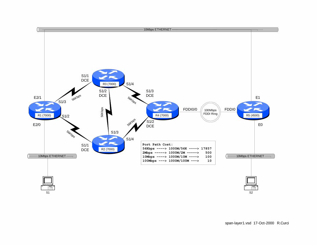
100MbpsFDDI Ring
10Mbps ETHERNET
10Mbps ETHERNET 10Mbps ETHERNET
R3 (7000)
R5 (4500)
R2 (7000)
R1 (7000) R4 (7000)
S1 S2
56Kbps
56Kbps
56K
bps
56Kbp
s
56KbpsS1/3
S1/1DCE
S1/2DCE
S1/3DCE
S1/4
S1/4
S1/2DCE
S1/1DCE
S1/2
E2/0
E2/1 E1
E0
FDDI0FDDI0/0
span-layer1.vsd 17-Oct-2000 R.Curci
S1/3
Port Path Cost:56Kbps ----> 1000M/56K ----> 178572Mbps -----> 1000M/2M -----> 50010Mbps ----> 1000M/10M ----> 100100Mbps ---> 1000M/100M ---> 10

C:\itl\countinf.doc Page 1 12/12/00
INTERNET TEACHING LAB: COUNT TO INFINITY LAB
NOTES:RIP Version 1 ProtocolSpllit-Horizon is enabled.
countinf.vsd 06-Dec-2000 R.Curci
COUNT-TO -INFINITY LAB
S1/3
R4 (7000)
R3 (7000)
R2 (7000)R1 (7000)
S1/1DCE
.2
.2
.3S1/4
.3 .3
S1/2DCE
S1/1DCE
S1/3DCE.4
S1/2
S1/3 .1
.1
L O O P B A C K 0
192.168.44.4/24
192.168.34.0/24
192.168.23.0/24
192.168.12.0/24
192.168.13.0/24
Helpful Commands:debug ip routingdebug ip ripdebug ip rip eventsshow ip protocolsshow ip routeshow cdp neighbor
REFERENCE:See Computer Networks3rd Ed, Tanenbaumpages 357-359 andfigure 5-12
TEST PROCEDURE:1. Configure routers per diagram with RIP version 1.2. Wait until RIP has converged.3. Reconfigure R3 to filter all RIP annoucements received on port S1/4 from R4.4. Watch the "debug ip rip" and "debug ip rip event" messages to see the routing table changes and routing announcements. Continue to observe until the routing tables on R1, R2, and R3 have converged.
"BREAK" thenetwork bydisabling thereceipt of routingannoucementshere.
OVERVIEW In this lab, we will explore the “count to infinity” problem of distance vector routing protocols such as RIP version 1. (For background information, read Tanenbaum’s Computer Networks 3rd Edition pages 357 through 359.) Normally, routers with distance vector routing protocols implement the split horizon algorithm where they will not advertise a network route out an interface to a neighbor from whom the route was learned. This can help reduce the convergence time, the time it takes the routing tables in each router to reach a steady state. We will configure the lab network on routers R1, R2, R3, and R4 as shown on the diagram above. By configuring routers R1, R2, and R3 in a cycle, we will attempt to defeat the split horizon hack and will try to demonstrate the count to infinity problem, the problem where distance vector routing protocols can take a very long time to reach convergence. Routers R1, R2, and R3 are connected with serial links in the shape of a triangle. R3 also has a serial link to R4. R4 has a loopback interface to network 192.168.44.0/24 which we will simply call “network 44”. This lab network contains five IP networks that will be abbreviated as shown in the following table.

C:\itl\countinf.doc Page 2 12/12/00
IP NETWORK ABBREVIATION 192.168.12.0/24 12 192.168.13.0/24 13 192.168.23.0/24 23 192.168.34.0/24 34 192.168.44.0/24 44 [IP Networks in this Lab] We will perform the following experiment:
1. Configure the network as in the above diagram with RIP version 1 protocol and wait for RIP to converge to a steady state.
2. Examine the routing tables and verify that each router has a route for networks 12, 13, 23, 34, and 44. We are especially interested in network 44 on the loopback interface of R4.
3. “Break” the connection between R3 and R4 by installing an access list on R3’s Serial1/4 interface that blocks RIP traffic received R4.
4. Examine the routing announcements on R1, R2, and R3 and watch how their routing tables change the R3---R4 connection is “broken.” Pay particular attention to network 44 which is no longer reachable but this will not be immediately known to router R3. We expect the routing metric on routers R1, R2, and R3 for network 44 to gradually increase, by one hop at a time, until a hop count of 16 or RIP infinity is reached.
BACKGROUND The RIP protocol uses four adjustable timers to control its operation. There is a single UPDATE timer and an instance of the INVALID, HOLDDOWN, and FLUSH timers for each entry in the routing table.
- UPDATE This timer controls how frequently a router announces routes to its neighbors. By default, this occurs every 30 seconds.
- INVALID This controls how long after not hearing an update for a route that the route will be declared invalid. By default, this timer is set to 180 seconds or 3 minutes which represents 6 RIP update cycles. It is restarted whenever a route is received.
- HOLDDOWN This controls how long after a route has been invalidated a router will wait before accepting a new route of a higher metric. This helps reduce the count-to-infinity problem. By default, this timer is set to 180 seconds or 3 minutes.

C:\itl\countinf.doc Page 3 12/12/00
- FLUSH This timer controls when a routing table entry is removed. It restarts every time a route is received and runs concurrently with the INVALID and HOLDDOWN timers. When the FLUSH timer has expired for a route, the route is removed from the routing table. The FLUSH timer expires before the HOLDDOWN timer, so HOLDDOWN never runs for its complete cycle.
The “show ip protocols” router command displays the current values for the RIP timers, as well as a list of routers from whom RIP announcements have been received:
r3#show ip protocols Routing Protocol is "rip" Sending updates every 30 seconds, next due in 6 seconds Invalid after 180 seconds, hold down 180, flushed after 240 Outgoing update filter list for all interfaces is not set Incoming update filter list for all interfaces is not set Redistributing: rip Default version control: send version 1, receive any version Interface Send Recv Key -chain Serial1/1 1 1 2 Serial1/2 1 1 2 Serial1/4 1 1 2 Routing for Networks: 192.168.13.0 192.168.23.0 192.168.34.0 Routing Information Sources: Gateway Distance Last Update 192.168.34.4 120 00:00:03 192.168.13.1 120 00:00:16 192.168.23.2 120 00:00:04 Distance: (default is 120) r3#
STEP1 – Configure the Network: For this exercise, we will only need to use routers R1, R2, R3, and R4. Configure these routers by erasing their configurations and pasting the following configuration information into the routers. Note that the “COMMON” section should be applied to all 4 routers, and the other sections as appropriate. For more information on router configuration basics, see the “Basic Router Configuration” lab.

C:\itl\countinf.doc Page 4 12/12/00
INITIAL ROUTER CONFIGURATION: COMMON: service timestamp debug uptime enable password cisco no ip domain-lookup ip classless line con 0 exec-timeout 0 0 line vty 0 4 password cisco login R1: hostname r1 interface Serial1/2 description Link to R2 S1/1 ip address 192.168.12.1 255.255.255.0 no shutdown interface Serial1/3 description Link to R3 S1/1 ip address 192.168.13.1 255.255.255.0 no shutdown router rip network 192.168.12.0 network 192.168.13.0 R2: hostname r2 interface Serial1/1 description Link to R1 S1/2 ip address 192.168.12.2 255.255.255.0 clockrate 2000000 no shutdown interface Serial1/3 description Link to R3 S1/2 ip address 192.168.23.2 255.255.255.0 no shutdown router rip network 192.168.12.0
network 192.168.23.0 R3: hostname r3 interface Serial1/1 description Link to R1 S1/3 ip address 192.168.13.3 255.255.255.0 clockrate 2000000 no shutdown interface Serial1/2 description Link to R2 S1/3 ip address 192.168.23.3 255.255.255.0 clockrate 2000000 no shutdown interface Serial1/4 description Link to R4 S1/3 ip address 192.168.34.3 255.255.255.0 no shutdown router rip network 192.168.13.0 network 192.168.23.0 network 192.168.34.0 R4: hostname r4 interface Loopback0 ip address 192.168.44.4 255.255.255.0 no shutdown interface Serial1/3 description Link to R3 S1/4 ip address 192.168.34.4 255.255.255.0 clockrate 2000000 no shutdown router rip network 192.168.44.0 network 192.168.34.0
STEP2 – Examine Routing Tables: Output from the “show ip route” command on each of the four routers is shown below. Note that routes for the same 5 networks appear on each router. For each router, networks that are directly connected prefixed with “C” for Connected while those learned through RIP are prefixed with “R”. Note that for the RIP entries in the square brackets are the administrative distance (120 for RIP) and the RIP hop count metric which are boldfaced. You will also notice sometimes where there are more than one entry for the same network. For example, notice that router R1 has two entries for network 23 both with metric 1. This is because there are two equal cost paths from R1 to network 23, one via interface Serial1/2 and the other via interface Serial1/3.

C:\itl\countinf.doc Page 5 12/12/00
r1#sh ip route Codes: C - connected, S - static, I - IGRP, R - RIP, M - mobile, B - BGP R 192.168.44.0/24 [120/2] via 192.168.13.3, 00:00:20, Serial1/3 R 192.168.34.0/24 [120/1] via 192.168.13.3, 00:00:20, Serial1/3 C 192.168.12.0/24 is directly connected, Serial1/2 C 192.168.13.0/24 is directly connected, Serial1/3 R 192.168.23.0/24 [120/1] via 192.168.13.3, 00:00:20, Serial1/3 [120/1] via 192.168.12.2, 00:00:07, Serial1/2 r2#sh ip route Codes: C - connected, S - static, I - IGRP, R - RIP, M - mobile, B - BGP R 192.168.44.0/24 [120/2] via 192.168.23.3, 00:00:06, Serial1/3 R 192.168.34.0/24 [120/1] via 192.168.23.3, 00:00:06, Serial1/3 C 192.168.12.0/24 is directly connected, Serial1/1 R 192.168.13.0/24 [120/1] via 192.168.12.1, 00:00:19, Serial1/1 [120/1] via 192.168.23.3, 00:00:07, Serial1/3 C 192.168.23.0/24 is directly connected, Serial1/3 r3#sh ip route Codes: C - connected, S - static, I - IGRP, R - RIP, M - mobile, B - BGP R 192.168.44.0/24 [120/1] via 192.168.34.4, 00:00:04, Serial1/4 C 192.168.34.0/24 is directly connected, Serial1/4 R 192.168.12.0/24 [120/1] via 192.168.13.1, 00:00:27, Serial1/1 [120/1] via 192.168.23.2, 00:00:27, Serial1/2 C 192.168.13.0/24 is directly connected, Serial1/1 C 192.168.23.0/24 is directly connected, Serial1/2 r4#show ip route Codes: C - connected, S - static, I - IGRP, R - RIP, M - mobile, B - BGP C 192.168.44.0/24 is directly connected, Loopback0 C 192.168.34.0/24 is directly connected, Serial1/3 R 192.168.12.0/24 [120/2] via 192.168.34.3, 00:00:20, Serial1/3 R 192.168.13.0/24 [120/1] via 192.168.34.3, 00:00:21, Serial1/3 R 192.168.23.0/24 [120/1] via 192.168.34.3, 00:00:21, Serial1/3
STEP3 – “BREAK” the R3— R4 Connection: We will now break the connection between R3 and R4 such that R3 will no longer hear advertisements for network 44. Instead of unplugging the cable where R3 would immediately notice the that connection went down, we will be sneaky and instead install an access list on R3’s interface Serial1/4 input to prevent it from hearing any RIP advertisements. From router R3’s RIP process perspective, it will not have any indication of any problems except that it will no longer hear advertisements for network 44.
! First turn on debugging so we can se e what is happening: r3# debug ip rip r3# debug ip rip events r3# term monitor ! Now create an access list and apply to deny traffic from R4: r3# config term r3(config)# no access-list 1 r3(config)# access-list 1 deny any r3(config)# interface Serial1/4 r3(config-if)# ip access-group 1 in

C:\itl\countinf.doc Page 6 12/12/00
STEP4 – Examine Routing Table and Announcement Changes:
Router R3 was reconfigured to filter out all RIP updates from R4 at 23:11:00. Here are the messages from “debug ip rip” and “debug ip rip events” on R3:
(R3 continues to advertise network 44 with metric 2 for about 3 minutes) 23:11:00: network 192.168.44.0, metric 2 23:11:27: network 192.168.44.0, metric 2 23:11:56: network 192.168.44.0, metric 2 23:12:25: network 192.168.44.0, metric 2 23:12:51: network 192.168.44.0, metric 2 23:13:18: network 192.168.44.0, metric 2 23:13:46: network 192.168.44.0, metric 2 23:14:16: network 192.168.44.0, metric 16 (advertising unreachable) 23:14:16: RT: flushed route to 192.168.44.0 via 192. 168.34.4 (Serial1/4) 23:14:16: RT: no routes to 192.168.44.0, entering holddown 23:15:13: RT: garbage collecting entry for 192.168.44.0 23:15:13: RIP: sending v1 update to 255.255.255.255 via Serial1/1 23:15:13: (First update without any route to network 192.168.44.0) 23:15:13: network 192.168.34.0, metric 1 23:15:13: network 192.168.23.0, metric 1 23:15:13: RIP: Update contains 2 routes 23:15:13: RIP: Update queued 23:15:14: RIP: Update sent via Serial1/1
Here are the debug messages captured on router R1:
23:14:16: RIP: received v1 update from 192.168.13.3 on Serial1/3 23:14:16: 192.168.44.0 in 16 hops (inaccessible) 23:14:16: RT: delete route to 192.168.44.0 via 192.168.13.3, rip metric [120/2] 23:14:16: RT: no routes to 192.168.44.0, entering holddown 23:17:22: RT: 192.168.44.0 came out of holddown 23:17:56: RT: garbage collecting entry for 192.168.44.0
After “breaking” the R3— R4 connection, R3 continues to advertise network 44 to its neighbors with metric 44 every 30 seconds. About 3 minutes after the “break”, the INVALID timer expires and R3’s entry for network 44 is marked as INVALID. It will still use this route, but will not advertise it as reachable to its neighbors. R3 network 44 advertisements now have metric 16 or unreachable. Since R3’s route for network 44 is now in HOLDDOWN, it will not accept any advertisements for this network with a metric greater than 2 preventing it from learning an incorrect route from R1 or R2. After approximately 4 minutes after the “break”, the FLUSH timer expires and the route indicates “gabage collecting entry for 192.168.44.0” and the entry to network 44 is completely removed. In this example, routers R1, R2, and R3 marked their routes to network 44 with metric 16 or unreachable after just over 3 minutes after the “break” and converged to a consistent state. This is much faster than we would have predicted from Tanenbaum. The CISCO use of the HOLDDOWN timer when a router will not accept routes with a higher metric and the use of a technique called “poison reverse” where a router advertises a network with metric 16 or unreachable help the routing tables converge more quickly than predicted.

NOTES:RIP Version 1 ProtocolSpllit-Horizon is enabled.
countinf.vsd 06-Dec-2000 R.Curci
COUNT-TO-INFINITY LAB
S1/3
R4 (7000)
R3 (7000)
R2 (7000)R1 (7000)
S1/1DCE
.2
.2
.3S1/4
.3 .3
S1/2DCE
S1/1DCE
S1/3DCE.4
S1/2
S1/3 .1
.1
LOOPBACK0
192.168.44.4/24
192.168.34.0/24
192.168.23.0/24
192.168.12.0/24
192.168.13.0/24
Helpful Commands:debug ip routingdebug ip ripdebug ip rip eventsshow ip protocolsshow ip routeshow cdp neighbor
REFERENCE:See Computer Networks3rd Ed, Tanenbaumpages 357-359 andfigure 5-12
TEST PROCEDURE:1. Configure routers per diagram with RIP version 1.2. Wait until RIP has converged.3. Reconfigure R3 to filter all RIP annoucements received on port S1/4 from R4.4. Watch the "debug ip rip" and "debug ip rip event" messages to see the routing table changes and routing announcements. Continue to observe until the routing tables on R1, R2, and R3 have converged.
"BREAK" thenetwork bydisabling thereceipt of routingannoucementshere.