fsp) for the 5th generation intel® core™ intel® firmware support package (intel® fsp) for the...
TRANSCRIPT

Document Number: 334348-001
Intel® Firmware Support Package (Intel®
FSP) for the 5th Generation Intel® Core™
i5-5350U Processor Evaluation Kit Based
on Intel® Intelligent System Extended
(ISX) Form Factor Reference Design
User Guide
April 2016
<Enter classification here: leave blank if Public, or enter Intel Confidential if
CNDA is required>

Intel® Firmware Support Package (Intel® FSP) for the 5th Generation Intel® Core™ i5-5350U Processor Evaluation
Kit Based on Intel® Intelligent System Extended (ISX) Form Factor Reference Design
User Guide April 2016
2 Classification Document Number: 334348-001
You may not use or facilitate the use of this document in connection with any infringement or other legal analysis concerning Intel products
described herein. You agree to grant Intel a non-exclusive, royalty-free license to any patent claim thereafter drafted which includes subject matter
disclosed herein
No license (express or implied, by estoppel or otherwise) to any intellectual property rights is granted by this document.
All information provided here is subject to change without notice. Contact your Intel representative to obtain the latest Intel product specifications
and roadmaps.
The products described may contain design defects or errors known as errata which may cause the product to deviate from published
specifications. Current characterized errata are available on request.
Copies of documents which have an order number and are referenced in this document may be obtained by calling 1-800-548-4725 or by visiting:
http://www.intel.com/design/literature.htm
Intel technologies’ features and benefits depend on system configuration and may require enabled hardware, software or service activation. Learn
more at http://www.intel.com/ or from the OEM or retailer.
No computer system can be absolutely secure.
Intel and the Intel logo are trademarks of Intel Corporation in the U.S. and/or other countries.
*Other names and brands may be claimed as the property of others.
Copyright © 2016, Intel Corporation. All rights reserved.

Intel® Firmware Support Package (Intel® FSP) for the 5th Generation Intel® Core™ i5-5350U Processor Evaluation
Kit Based on Intel® Intelligent System Extended (ISX) Form Factor Reference DesignTitle
April 2016 User Guide
Document Number: 334348-001 Classification 3
Contents
1.0 Introduction ............................................................................................................................................ 6
1.1 About Intel FSP and coreboot ............................................................................................................... 6
1.2 About This Evaluation Kit ......................................................................................................................... 7
1.3 Terminology ...................................................................................................................................................... 8
1.4 Reference Documents ................................................................................................................................ 9
1.5 Block Diagram ............................................................................................................................................... 10
2.0 Implementing coreboot ................................................................................................................. 12
2.1 Introduction ..................................................................................................................................................... 12
2.2 Compiling coreboot .................................................................................................................................... 13
2.2.1 Build Environment Operating System ........................................................................ 13 2.2.2 coreboot Compilation Steps .............................................................................................. 13
2.3 Customizing coreboot Source Code for the 5th Generation Intel® Core™ (U
series) Processor Platform .................................................................................................................... 14
2.3.1 CPU Microcode for Broadwell-U F0 Stepping Update ....................................... 15 2.3.2 Super Input Output (SIO) Chip (IT8728F) Initialization ............................... 16 2.3.3 PCI Device ID Modification ................................................................................................. 20
2.4 Compiling the Different Payloads ..................................................................................................... 23
2.4.1 SeaBIOS (Legacy) .................................................................................................................... 23 2.4.2 TianoCore (UEFI) ...................................................................................................................... 24 2.4.3 U-Boot (coreboot default payload) ............................................................................... 24
2.5 Compiling coreboot with Different Payloads ............................................................................. 25
3.0 Deploying the SPI Flash Image ................................................................................................. 27
3.1 Replacing the Proprietary BIOS with Customized coreboot ........................................... 27
3.1.1 Decomposing the full SPI flash image with FITC ................................................ 27 3.1.2 Composing the Full SPI Flash Image file using FITC ....................................... 28
3.2 Backing Up the Proprietary SPI Flash Image (Reading the SPI Flash Chip) ...... 29
3.2.1 DediProg Programmer (Windows) ................................................................................ 30 3.2.2 Flashrom Utility (Linux) ........................................................................................................ 34
3.3 Flashing the SPI Flash Chip .................................................................................................................. 35
3.3.1 DediProg Programmer (Windows) ................................................................................ 35 3.3.2 Flashrom Utility (Linux) ........................................................................................................ 38
4.0 Customized coreboot: Booting and Installing the Operating System ................ 39
4.1 coreboot with SeaBIOS Payload ........................................................................................................ 39
4.2 coreboot with UEFI Payload ................................................................................................................. 39
4.3 coreboot with U-Boot Payload ............................................................................................................ 42
5.0 coreboot Debugging Methods..................................................................................................... 44

Intel® Firmware Support Package (Intel® FSP) for the 5th Generation Intel® Core™ i5-5350U Processor Evaluation
Kit Based on Intel® Intelligent System Extended (ISX) Form Factor Reference Design
User Guide April 2016
4 Classification Document Number: 334348-001
5.1 Post Codes ........................................................................................................................................................ 44
5.2 Serial Debug ................................................................................................................................................... 44
Figures
Figure 1. coreboot Firmware Stack ......................................................................................................................... 7 Figure 2. Evaluation Kit Proprietary BIOS (Aptio BIOS) ........................................................................... 8 Figure 3. Block Diagram of the Evaluation Kit .............................................................................................. 10 Figure 4. Intel FSP Sample Boot Flow ................................................................................................................. 11 Figure 5. SIO (EC) Chip Location............................................................................................................................ 16 Figure 6. coreboot Configuration ............................................................................................................................ 25 Figure 7. Flash Image Tool (FITC) ......................................................................................................................... 29 Figure 8. DediProg SF600 Programmer ............................................................................................................. 30 Figure 9. Connecting DediProg SF600 to the Evaluation Kit ............................................................... 31 Figure 10. Selecting Memory Type in DediProg .............................................................................................. 32 Figure 11. Reading the SPI Chip ................................................................................................................................ 33 Figure 12. Saving the SPI Chip Content ............................................................................................................... 34 Figure 13. Connecting DediProg SF600 to the Evaluation Kit ............................................................... 36 Figure 14. Loading the BIOS Binary Image File .............................................................................................. 37 Figure 15. DediProg Batch Operation ..................................................................................................................... 38 Figure 16. SeaBIOS Boot Menu .................................................................................................................................. 39 Figure 17. UEFI Setup Menu ......................................................................................................................................... 40 Figure 18. UEFI Boot Menu ............................................................................................................................................ 40 Figure 19. Ubuntu Operating System ..................................................................................................................... 41 Figure 20. POST Card ........................................................................................................................................................ 44 Figure 21. DB9 Serial Port Bracket to 10 Pin Header Serial Cable .................................................... 45 Figure 22. Serial Debug Connection ........................................................................................................................ 46 Figure 23. Picocom Utility ............................................................................................................................................... 47
Tables
Table 1. Terminology ...................................................................................................................................................... 8 Table 2. Technical Reference Documents and Tools ................................................................................. 9 Table 3. Supported Features of the FSP Binary and Evaluation Kit ............................................. 13 Table 4. CPU Microcode Update Guide .............................................................................................................. 15

Intel® Firmware Support Package (Intel® FSP) for the 5th Generation Intel® Core™ i5-5350U Processor Evaluation
Kit Based on Intel® Intelligent System Extended (ISX) Form Factor Reference DesignTitle
April 2016 User Guide
Document Number: 334348-001 Classification 5
Revision History
Date Revision Description
April 2016 1.0 Initial release.
§

Introduction
Intel® Firmware Support Package (Intel® FSP) for the 5th Generation Intel® Core™ i5-5350U Processor Evaluation
Kit Based on Intel® Intelligent System Extended (ISX) Form Factor Reference Design
User Guide April 2016
6 Classification Document Number: 334348-001
1.0 Introduction
The following user guide describes replacing the proprietary firmware (BIOS or UEFI) of
the 5th Generation Intel® Core™ (U series) Processor evaluation kit with coreboot,
formerly known as LinuxBIOS. The procedure to integrate the Intel Firmware Support
Package (FSP) binary into coreboot, an open-source firmware stack, can be performed
with minimal conversion effort. This allows for self-customization and self-integration
to be performed by OEMs with experience in developing firmwares. They can download
and customize open source firmware stacks such as U-Boot, UEFI, and coreboot to be
integrated with Intel FSP.
1.1 About Intel FSP and coreboot
Intel FSP is the engine that provides the silicon initialization code for Intel chips. Each
Intel silicon and its companion chip will have their own Intel FSP. Intel FSP initializes
the CPU, memory controller, chipset, and certain bus interfaces, if necessary. The Intel
FSP provides chipset and processor initialization in a format that can easily be
incorporated into many boot loaders including coreboot.
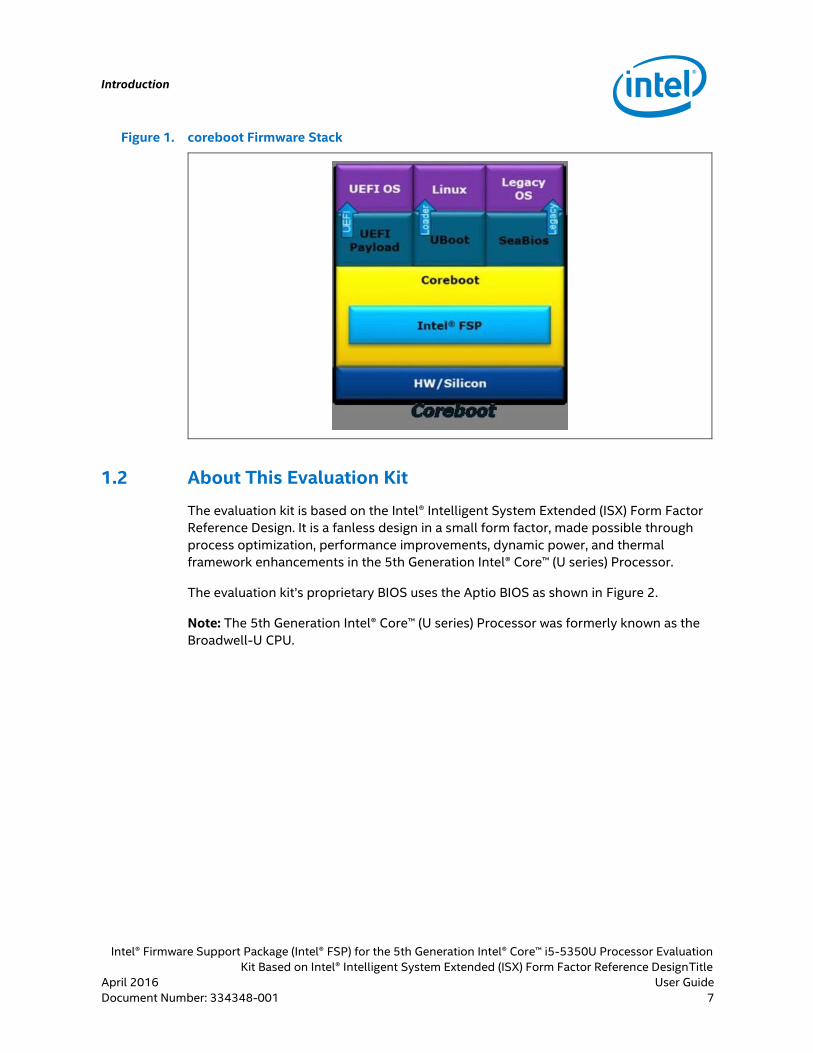
The coreboot hardware initialization framework handles the Intel FSP silicon
initialization API, configures system peripherals, and loads the payload. coreboot in
itself is considered a minimalistic code for initializing the hardware. It does provide
services required by an OS. After the initialization, it jumps to a specific payload which
provide services required to load and boot an OS. coreboot supports a number of
different payloads that are used for disk boot, network boot, and legacy BIOS services.
Although coreboot is often used to boot Linux OS, depending on the specified payload,
it can also boot most versions of BSD, Windows, or any other OS.
Introduction
Intel® Firmware Support Package (Intel® FSP) for the 5th Generation Intel® Core™ i5-5350U Processor Evaluation
Kit Based on Intel® Intelligent System Extended (ISX) Form Factor Reference DesignTitle
April 2016 User Guide
Document Number: 334348-001 Classification 7
Figure 1. coreboot Firmware Stack
1.2 About This Evaluation Kit
The evaluation kit is based on the Intel® Intelligent System Extended (ISX) Form Factor
Reference Design. It is a fanless design in a small form factor, made possible through
process optimization, performance improvements, dynamic power, and thermal
framework enhancements in the 5th Generation Intel® Core™ (U series) Processor.
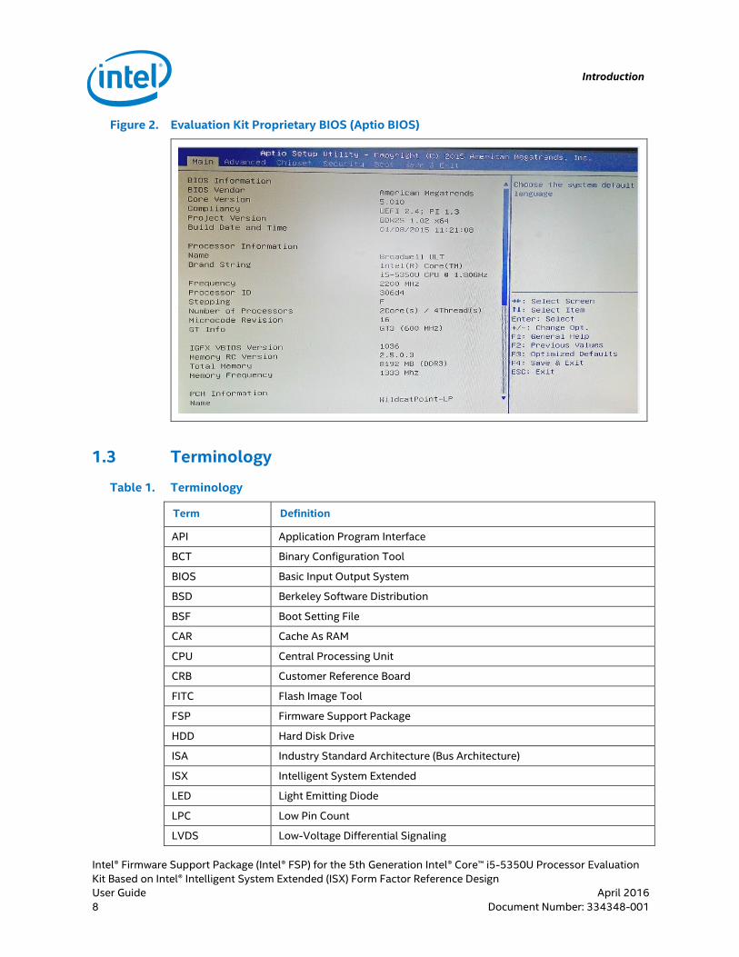
The evaluation kit’s proprietary BIOS uses the Aptio BIOS as shown in Figure 2.
Note: The 5th Generation Intel® Core™ (U series) Processor was formerly known as the
Broadwell-U CPU.
Introduction
Intel® Firmware Support Package (Intel® FSP) for the 5th Generation Intel® Core™ i5-5350U Processor Evaluation
Kit Based on Intel® Intelligent System Extended (ISX) Form Factor Reference Design
User Guide April 2016
8 Classification Document Number: 334348-001
Figure 2. Evaluation Kit Proprietary BIOS (Aptio BIOS)
1.3 Terminology
Table 1. Terminology
Term Definition
API Application Program Interface
BCT Binary Configuration Tool
BIOS Basic Input Output System
BSD Berkeley Software Distribution
BSF Boot Setting File
CAR Cache As RAM
CPU Central Processing Unit
CRB Customer Reference Board
FITC Flash Image Tool
FSP Firmware Support Package
HDD Hard Disk Drive
ISA Industry Standard Architecture (Bus Architecture)
ISX Intelligent System Extended
LED Light Emitting Diode
LPC Low Pin Count
LVDS Low-Voltage Differential Signaling
Introduction
Intel® Firmware Support Package (Intel® FSP) for the 5th Generation Intel® Core™ i5-5350U Processor Evaluation
Kit Based on Intel® Intelligent System Extended (ISX) Form Factor Reference DesignTitle
April 2016 User Guide
Document Number: 334348-001 Classification 9
Term Definition
ME Intel Management Engine
NFS Network File System
OS Operating System
PCI Peripheral Component Interface
PCIe Peripheral Component Interface Express
POST Power-On Self Test
SATA Serial Advanced Technology Attachment
SIO Super Input Output
SOC System On Chip
SPI Serial Peripheral Interface
TXE Trusted Execution Engine
UEFI Unified Extensible Firmware Interface
USB Universal Serial Bus
VCC Used to signify circuit logic voltage
VGA Video Graphics Array
1.4 Reference Documents
Table 2. Technical Reference Documents and Tools
Document Description Document Number
5th Generation Intel® Core™ i5-5350U Processor Evaluation Kit Based on Intel® Intelligent System Extended (ISX) Form Factor Reference Design Product User Manual - Revision 2.0
CDI#557208
Reference coreboot Image (Can be used with Broadwell platform (Broadwell U + Wildcat Point) on Whitetip Mountain board)
CDI#551352
Intel® Firmware Support Package (FSP) (For Broadwell platform (Broadwell U + Wildcat Point) on Whitetip Mountain board)
CDI#551350
5th Generation Intel® Core™ i5-5350U Processor Evaluation Kit Based on Intel® Intelligent System Extended (ISX) Form Factor Reference Design - Schematic and Board File
CDI#556749
5th Generation Intel® Core™ i5-5350U Processor Evaluation Kit Based on Intel® Intelligent System Extended (ISX) Form Factor Reference Design - BIOS Image (Aptio BIOS)
CDI#557335
Microcode Update for Broadwell-U, F0 Stepping IBP#459855
Intel Management Engine 10.0.45.1024 (BDW/WPT and HSW/LPT-LP SKUs) Tool
VIP#107610
5th Generation Intel® Core™ i5-5350U Processor Evaluation Kit Based on Intel® Intelligent System Extended (ISX) Form Factor Reference
CDI#557276
Introduction
Intel® Firmware Support Package (Intel® FSP) for the 5th Generation Intel® Core™ i5-5350U Processor Evaluation
Kit Based on Intel® Intelligent System Extended (ISX) Form Factor Reference Design
User Guide April 2016
10 Classification Document Number: 334348-001
Document Description Document Number
Design - Power-on and Functionality Test Plan
Broadwell-U Mobile Processor Platform - Best Known Configuration CDI#539245 CDI#558327
BDW_UY_NDA_Spec_Update_rev016-stepping-difference-D0 CDI#550510
1.5 Block Diagram
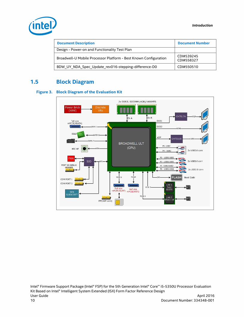
Figure 3. Block Diagram of the Evaluation Kit

Introduction
Intel® Firmware Support Package (Intel® FSP) for the 5th Generation Intel® Core™ i5-5350U Processor Evaluation
Kit Based on Intel® Intelligent System Extended (ISX) Form Factor Reference DesignTitle
April 2016 User Guide
Document Number: 334348-001 Classification 11
Figure 4. Intel FSP Sample Boot Flow
§
Implementing coreboot
Intel® Firmware Support Package (Intel® FSP) for the 5th Generation Intel® Core™ i5-5350U Processor Evaluation
Kit Based on Intel® Intelligent System Extended (ISX) Form Factor Reference Design
User Guide April 2016
12 Classification Document Number: 334348-001
2.0 Implementing coreboot
2.1 Introduction
coreboot is an open source platform that delivers fast and secure boot experience on
modern computers and embedded systems. As an open source project, it provides
OEMs with maximum control over the technology.
The coreboot package (CDI#551352) has been released by Intel for 5th Generation
Intel Core processors (codename Broadwell) and their chipsets. Included in this
coreboot package is the Intel FSP binary (CDI#551350) which has been validated on the
following customer reference boards (CRB):
Whitetip Mountain 1 CRB with Broadwell processor and Wildcat Point-LP PCH
Lava Canyon 2 CRB with Broadwell processor and Lynx Point PCH
Lava Canyon CRB with Haswell processor and Lynx Point PCH
The Intel FSP directory contains primarily the FSP binary file (.fd file extension), Boot
Setting File (BSF, .bsf file extension), and two subdirectorys with sample header files
and source code. Intel FSP sometimes includes the VGA BIOS file and CPU microcode.
Using the Boot Configuration Tool (BCT), the Intel FSP internal configuration can be
further customized; thus eliminating the need to manually change the internal
configuration of the Intel FSP.
A customized version of coreboot based on the Whitetip Mountain 1 CRB source code
is used for the 5th Generation Intel® Core™ (U series) Processor evaluation kit as both
platforms share the same type of processor, memory, and chipset.

Implementing coreboot
Intel® Firmware Support Package (Intel® FSP) for the 5th Generation Intel® Core™ i5-5350U Processor Evaluation
Kit Based on Intel® Intelligent System Extended (ISX) Form Factor Reference DesignTitle
April 2016 User Guide
Document Number: 334348-001 Classification 13
Table 3. Supported Features of the FSP Binary and Evaluation Kit
FSP Binary (CDI#551350) 5th Generation Intel® Core™ (U series) Processor Platform
Supported Features
Broadwell D0 stepping with Wildcat
Point-LP PCH
Broadwell D0 stepping with Lynx
Point PCH
Haswell C0 stepping Lynx Point PCH
Memory detection and initialization
Supported memory types:
DDR3L 1333/1600, LPDDR3
1333/1600
Maximum memory size: 16GB
MTRR initialization on all processors
PCI Express initialization
SATA port initialization
EHCI and XHCI controller
initialization
Platform options configuration
using Intel BCT tool
Broadwell-U CPU, F0
stepping, 306D4, microcode
revision 0x16
Memory DDR3L 1333 MHz
Wildcat Point-LP PCH
SIO Chip (IT8728F)
2.2 Compiling coreboot
2.2.1 Build Environment Operating System
A Linux OS based on Ubuntu* 14.04 LTS, 32-bit is used as the build environment for
compiling and testing coreboot. The following evaluation and compilation tools are
used:
GCC 4.8
Make 3.81
IASL 20140214
AS GNU assembler version 2.24
Note: Other operating systems may be used for coreboot compilation but may require
some modifications to associate the files and default options with the compiler, linker
etc.
2.2.2 coreboot Compilation Steps
1. Download the coreboot source code file 551352_Broadwell_CB_GOLD.zip for the
Broadwell platform (Broadwell U + Wildcat Point) from Intel CDI#551352 source.

Implementing coreboot
Intel® Firmware Support Package (Intel® FSP) for the 5th Generation Intel® Core™ i5-5350U Processor Evaluation
Kit Based on Intel® Intelligent System Extended (ISX) Form Factor Reference Design
User Guide April 2016
14 Classification Document Number: 334348-001
2. Unzip the 551352_Broadwell_CB_GOLD.zip file to obtain the coreboot source code
tar ball file fsp_bootloader-coreboot-6d2cf13.tar.gz.
3. Unpack the fsp_bootloader-coreboot-6d2cf13.tar.gz file using the following
command.
$ tar -xvf fsp_bootloader-coreboot-6d2cf13.tar.gz
4. Modify the coreboot source code to adapt to the differences in the 5th Generation
Intel® Core™ (U series) Processor evaluation kit platform. Refer to Section 2.3 for
coreboot customization instructions.
5. Copy the White Tip Mountain 1 CRB config file into the root directory of the
coreboot source directory using the following command.
$ cd fsp_bootloader-coreboot-6d2cf13
$ cp -rf configs/config.wtm1_fsp .config
$ vi .config (Open .config file)
6. Verify that the .config file contains the following line codes. If the information is
mismatched, modify it to match the line code below.
CONFIG_MAINBOARD_PART_NUMBER="Broad Island Mini Industrial PC"
CONFIG_VGA_BIOS_ID="8086,1626"
CONFIG_MAINBOARD_SMBIOS_PRODUCT_NAME="Broad Island Mini
Industrial PC" CONFIG_SUPERIO_ITE_COMMON_ROMSTAGE=y
CONFIG_SUPERIO_ITE_IT8728F=y
7. Enter the following command to launch menuconfig. Save the changes and exit.
$ make menuconfig
8. Compile coreboot with the following command.
$ make
Note: This creates the final coreboot image file build/coreboot.rom (2MB file).
2.3 Customizing coreboot Source Code for the 5th Generation Intel® Core™ (U series) Processor Platform
Customizing the coreboot source code for the 5th Generation Intel® Core™ (U series)
Processor platform involves modifying the following:
Update the CPU Microcode
Initialize the SIO Chip
Modify the PCI Device ID
Note: The line codes highlighted in bold in the following sections indicate that
modifications are performed.

Implementing coreboot
Intel® Firmware Support Package (Intel® FSP) for the 5th Generation Intel® Core™ i5-5350U Processor Evaluation
Kit Based on Intel® Intelligent System Extended (ISX) Form Factor Reference DesignTitle
April 2016 User Guide
Document Number: 334348-001 Classification 15
2.3.1 CPU Microcode for Broadwell-U F0 Stepping Update
Each unique processor stepping/package combination has an associated microcode
update that, when applied, constitutes a supported processor (i.e., Specified Processor
= Processor Stepping + Microcode Update). The proper microcode update must be
loaded on each processor in a system. The proper microcode update is defined as the
latest microcode update available from Intel for a given family, model, and stepping of
the processor. Any processor that does not have the correct microcode update loaded
is considered to be operating out of specification. Contact your Intel Field
Representative to receive the latest microcode updates. The microcode patches can be
updated independently of FSP.
The following procedure provides the steps to update the CPU microcode.
Table 4. CPU Microcode Update Guide
Microcode Update
Microcode Update Package
Source Download
Processor Signature
Microcode Update Revision
MC0306D4_00 000022.TXT
MOB_P_64.EXE or MOB_P_57.EXE
IBP#459855 F0 Step: 000306D4 E0
Step: 000306D4
00000022
1. Obtain the microcode update file MC0306D4_00 000022.TXT for Broadwell-U CPU,
F0 stepping, 306D4 from the Intel IBP#459855 source.
2. Convert the text file MC0306D4_00 000022.TXT into the C header file format
MC0306D4_00000022.h.
Note: The conversion can be done manually by aligning the microcode instructions
data to the proper format (from .txt to.h file). Alternatively, Linux utilities (awk, sed) can
also be used to align the data to a certain format.
3. Unzip the 551352_Broadwell_CB_GOLD.zip file to obtain the coreboot source code
tar ball file fsp_bootloader-coreboot-6d2cf13.tar.gz and unpack it.
4. Copy the file MC0306D4_00000022.h into the coreboot source code directory
fsp_bootloader-coreboot-6d2cf13/src/vendorcode/intel/cpu/broadwell/microcode/
5. Edit the file ~/fsp_bootloader-coreboot-6d2cf13/src/cpu/intel/fsp_broadwell/
microcode/microcode_blob.c code in Line 25.
Line 25:
24 #include "m7240651_0000001c.h"// Haswell silicon on WTM1
25 #include "MC0306D4_00000022.h" // Broadwell F0
6. Add the CPU Device ID for the Intel Broadwell ULT in the fsp_bootloader-coreboot-
6d2cf13/src/cpu/intel/fsp_broadwell/broadwell_init.c file.
Line 512:

Implementing coreboot
Intel® Firmware Support Package (Intel® FSP) for the 5th Generation Intel® Core™ i5-5350U Processor Evaluation
Kit Based on Intel® Intelligent System Extended (ISX) Form Factor Reference Design
User Guide April 2016
16 Classification Document Number: 334348-001
511 { X86_VENDOR_INTEL, 0x40651 }, /* Intel Haswell (HSW-LP) */
512 { X86_VENDOR_INTEL, 0x306d4 }, /* Intel Broadwell ULT */
513 { 0, 0 },
7. After coreboot has been compiled (refer to Section 2.2 for compile instructions),
the CPU microcode binary image file cpu_microcode_blob.bin will be created in the
~/fsp_bootloader-coreboot-6d2cf13/build/ directory. The cpu_microcode_blob.bin
file will then be integrated with the coreboot image file (coreboot.rom).
2.3.2 Super Input Output (SIO) Chip (IT8728F) Initialization
The 5th Generation Intel® Core™ (U series) Processor evaluation kit platform has an SIO
chip (IT8728F) embedded into the mainboard for the Serial I/O (CDI#557208). As
shown in Figure 5, the serial ports (COM) and fan are connected to the SIO (EC) chip.
The SIO chip is interfaced with the mainboard via the LPC/ISA bus.
Note: The Whitetip Mountain 1 CRB does not use an SIO chip. The hardware difference
requires customizing the SIO initialization code for the 5th Generation Intel® Core™ (U
series) Processor evaluation kit.
Figure 5. SIO (EC) Chip Location
The following procedure describes the initialization of the SIO chip.
1. Add the config option for the SIO chip (IT8728F) in the fsp_bootloader-coreboot-
6d2cf13/src/mainboard/intel/wtm1_fsp/Kconfig file.
Line 19:
18 select VGA
19 select SUPERIO_ITE_IT8728F
20 select INCLUDE_MICROCODE_IN_BUILD if FSP_PACKAGE_DEFAULT
2. Add the Super I/O IT8728F initialization code in the fsp_bootloader-coreboot-
6d2cf13\src\mainboard\intel\wtm1_fsp\romstage.c file.
Line 38:
38 #include "gpio.h"
39 #include <superio/ite/common/ite.h>
40 #include <superio/ite/it8728f/it8728f.h>
41

Implementing coreboot
Intel® Firmware Support Package (Intel® FSP) for the 5th Generation Intel® Core™ i5-5350U Processor Evaluation
Kit Based on Intel® Intelligent System Extended (ISX) Form Factor Reference DesignTitle
April 2016 User Guide
Document Number: 334348-001 Classification 17
42 #define SERIAL_DEV PNP_DEV(0x2e, IT8728F_SP1)
43 #define GPIO_DEV PNP_DEV(0x2e, IT8728F_GPIO)
Line 74:
74 /* Super I/O IT8728F Initialization hook.
75 * This code should be called after port 0x2E/2F or 0x4E/4F
decoded, which
76 * will be done in early_pch.c, just adding a super I/O hook for
later usage.
77 * This hook will be called in
src\southbridge\intel\fsp_wildcatpoint\early_pch.c.
78 */
79
80 static void mainboard_superio_hook(void)
81 {
82 u8 byte;
83 device_t dev;
84
85 /* enable SIO LPC decode */
86 dev = PCI_DEV(0, 0x1f, 0);
87 byte = pci_read_config8(dev, 0x48);
88 byte |= 3;/* 2e, 2f */
89 pci_write_config8(dev, 0x48, byte);
90
91 /* enable serial decode */
92 byte = pci_read_config8(dev, 0x44);
93 byte |= (1 << 6); /* 0x3f8 */
94 pci_write_config8(dev, 0x44, byte);
95
96 post_code(0x88);
97
98 /* enable SB MMIO space */
99 outb(0x24, 0xcd6);
100 outb(0x1, 0xcd7);
101
Implementing coreboot
Intel® Firmware Support Package (Intel® FSP) for the 5th Generation Intel® Core™ i5-5350U Processor Evaluation
Kit Based on Intel® Intelligent System Extended (ISX) Form Factor Reference Design
User Guide April 2016
18 Classification Document Number: 334348-001
102 /* enable SIO clock */
103
104 ite_kill_watchdog(GPIO_DEV);
105 ite_enable_serial(SERIAL_DEV, CONFIG_TTYS0_BASE);
106 ite_enable_3vsbsw(GPIO_DEV);
107 }
Line 139:
139 /* Super IO IT8728F on BroadIsland board */
140 wake_from_s3 = early_pch_init(&mainboard_gpio_map,
mainboard_superio_hook, &rcba_config[0]);
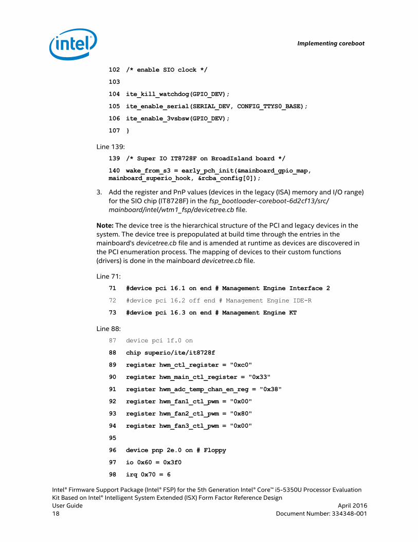
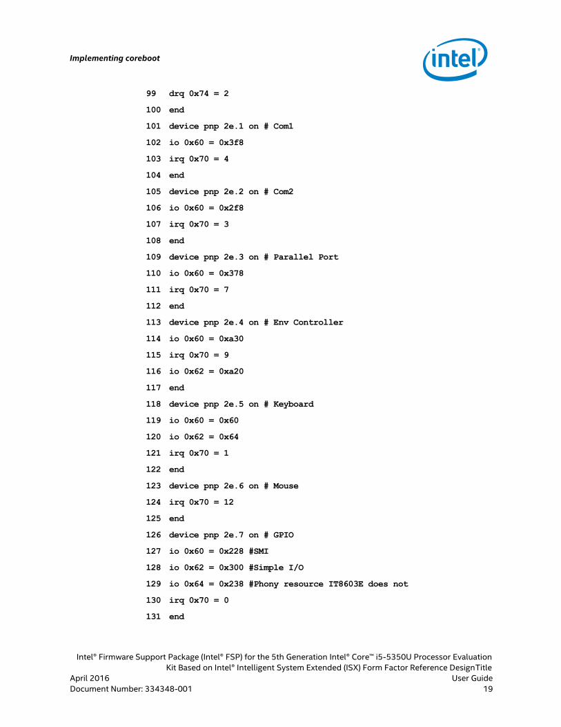
3. Add the register and PnP values (devices in the legacy (ISA) memory and I/O range)
for the SIO chip (IT8728F) in the fsp_bootloader-coreboot-6d2cf13/src/
mainboard/intel/wtm1_fsp/devicetree.cb file.
Note: The device tree is the hierarchical structure of the PCI and legacy devices in the
system. The device tree is prepopulated at build time through the entries in the
mainboard's devicetree.cb file and is amended at runtime as devices are discovered in
the PCI enumeration process. The mapping of devices to their custom functions
(drivers) is done in the mainboard devicetree.cb file.
Line 71:
71 #device pci 16.1 on end # Management Engine Interface 2
72 #device pci 16.2 off end # Management Engine IDE-R
73 #device pci 16.3 on end # Management Engine KT
Line 88:
87 device pci 1f.0 on
88 chip superio/ite/it8728f
89 register hwm_ctl_register = "0xc0"
90 register hwm_main_ctl_register = "0x33"
91 register hwm_adc_temp_chan_en_reg = "0x38"
92 register hwm_fan1_ctl_pwm = "0x00"
93 register hwm_fan2_ctl_pwm = "0x80"
94 register hwm_fan3_ctl_pwm = "0x00"
95
96 device pnp 2e.0 on # Floppy
97 io 0x60 = 0x3f0
98 irq 0x70 = 6
Implementing coreboot
Intel® Firmware Support Package (Intel® FSP) for the 5th Generation Intel® Core™ i5-5350U Processor Evaluation
Kit Based on Intel® Intelligent System Extended (ISX) Form Factor Reference DesignTitle
April 2016 User Guide
Document Number: 334348-001 Classification 19
99 drq 0x74 = 2
100 end
101 device pnp 2e.1 on # Com1
102 io 0x60 = 0x3f8
103 irq 0x70 = 4
104 end
105 device pnp 2e.2 on # Com2
106 io 0x60 = 0x2f8
107 irq 0x70 = 3
108 end
109 device pnp 2e.3 on # Parallel Port
110 io 0x60 = 0x378
111 irq 0x70 = 7
112 end
113 device pnp 2e.4 on # Env Controller
114 io 0x60 = 0xa30
115 irq 0x70 = 9
116 io 0x62 = 0xa20
117 end
118 device pnp 2e.5 on # Keyboard
119 io 0x60 = 0x60
120 io 0x62 = 0x64
121 irq 0x70 = 1
122 end
123 device pnp 2e.6 on # Mouse
124 irq 0x70 = 12
125 end
126 device pnp 2e.7 on # GPIO
127 io 0x60 = 0x228 #SMI
128 io 0x62 = 0x300 #Simple I/O
129 io 0x64 = 0x238 #Phony resource IT8603E does not
130 irq 0x70 = 0
131 end

Implementing coreboot
Intel® Firmware Support Package (Intel® FSP) for the 5th Generation Intel® Core™ i5-5350U Processor Evaluation
Kit Based on Intel® Intelligent System Extended (ISX) Form Factor Reference Design
User Guide April 2016
20 Classification Document Number: 334348-001
132 device pnp 2e.a off end # CIR
133 end #superio/ite/it8728f
134 end # LPC bridge
2.3.3 PCI Device ID Modification
2.3.3.1 VGA BIOS ID
The 5th Generation Intel® Core™ (U series) Processor platform has a VGA compatible
controller with the PCI ID [8086:1626].
1. Edit the fsp_bootloader-coreboot-6d2cf13/src/mainboard/intel/wtm1_fsp/Kconfig
file.
Line 53:
51 config VGA_BIOS_ID
52 string
53 default "8086,1626"
2. Edit the fsp_bootloader-coreboot-6d2cf13/src/northbridge/intel/fsp_broadwell/
Kconfig file.
Line 37:
35 config VGA_BIOS_ID
36 string
37 default "8086,1626"
3. Edit the fsp_bootloader-coreboot-6d2cf13/src/northbridge/intel/fsp_broadwell/
gma.c file.
Line 55:
53 case 0x80860a26:/* GT3 ULT */
54
55 case 0x80861626:/* Broadwell-U Integrated Graphics */
Line 268:
267 0x0a26, /* ULT GT3 */
268 0x1626, /* Broadwell-U Integrated Graphics */
269 0,
270 };

Implementing coreboot
Intel® Firmware Support Package (Intel® FSP) for the 5th Generation Intel® Core™ i5-5350U Processor Evaluation
Kit Based on Intel® Intelligent System Extended (ISX) Form Factor Reference DesignTitle
April 2016 User Guide
Document Number: 334348-001 Classification 21
2.3.3.2 Serial IO PCI Device ID
Add the PCI Device ID of the serial IO (DMA, I2C, SPI, and UART) and SDIO Controller for
the Wildcat Point-LP PCH.
Edit the fsp_bootloader-coreboot-6d2cf13/src/southbridge/intel/fsp_wildcatpoint/
serialio.c file.
Line 252:
251 static const unsigned short pci_device_ids[] = {
252 0x9c60, 0x9ce0, /* 0:15.0 - SDMA */
253 0x9c61, 0x9ce1, /* 0:15.1 - I2C0 */
254 0x9c62, 0x9ce2, /* 0:15.2 - I2C1 */
255 0x9c65, 0x9ce5, /* 0:15.3 - SPI0 */
256 0x9c66, 0x9ce6, /* 0:15.4 - SPI1 */
257 0x9c63, 0x9ce3, /* 0:15.5 - UART0 */
258 0x9c64, 0x9ce4, /* 0:15.6 - UART1 */
259 0x9c35, 0x9cb5, /* 0:17.0 - SDIO */
260 0
261 };
2.3.3.3 SMBUS PCI Device ID
The 5th Generation Intel® Core™ (U series) Processor platform has PCI ID [8086:9ca2]
for the Wildcat Point-LP SMBus Controller.
Edit the fsp_bootloader-coreboot-6d2cf13/src/southbridge/intel/fsp_wildcatpoint/
smbus.c file.
Line 103:
103 static const unsigned short pci_device_ids[] = { 0x1c22, 0x1e22,
0x9ca2, /* WildcatPoint */ 0 };
2.3.3.4 Serial IO Controller HID
Add the HID of I2C, SPI, UART, and SDIO Controller for the Wildcat Point-LP PCH.
Edit the fsp_bootloader-coreboot-6d2cf13/src/southbridge/intel/fsp_wildcatpoint/acpi/
serialio.asl file.
Line 157:
156 // Serial IO I2C0 Controller

Implementing coreboot
Intel® Firmware Support Package (Intel® FSP) for the 5th Generation Intel® Core™ i5-5350U Processor Evaluation
Kit Based on Intel® Intelligent System Extended (ISX) Form Factor Reference Design
User Guide April 2016
22 Classification Document Number: 334348-001
157 Name (_HID, "INT3432")
158 Name (_UID, 1)
159 Name (_ADR, 0x00150001)
Line 207:
206 // Serial IO I2C1 Controller
207 Name (_HID, "INT3433")
208 Name (_UID, 1)
209 Name (_ADR, 0x00150002)
Line 257:
256 // Serial IO SPI0 Controller
257 Name (_HID, "INT3430")
258 Name (_UID, 1)
259 Name (_ADR, 0x00150003)
Line 294:
293 // Serial IO SPI1 Controller
294 Name (_HID, "INT3431")
295 Name (_UID, 1)
296 Name (_ADR, 0x00150004)
Line 344:
343 // Serial IO UART0 Controller
344 Name (_HID, "INT3434")
345 Name (_UID, 1)
346 Name (_ADR, 0x00150005)
Line 394:
393 // Serial IO UART1 Controller
394 Name (_HID, "INT3435")
395 Name (_UID, 1)
396 Name (_ADR, 0x00150006)
Line 431:
430 // Serial IO SDIO Controller
431 Name (_HID, "INT3436")
432 Name (_UID, 1)
Implementing coreboot
Intel® Firmware Support Package (Intel® FSP) for the 5th Generation Intel® Core™ i5-5350U Processor Evaluation
Kit Based on Intel® Intelligent System Extended (ISX) Form Factor Reference DesignTitle
April 2016 User Guide
Document Number: 334348-001 Classification 23
433 Name (_ADR, 0x00170000)
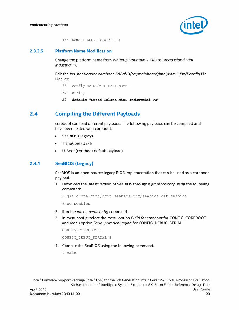
2.3.3.5 Platform Name Modification
Change the platform name from Whitetip Mountain 1 CRB to Broad Island Mini
Industrial PC.
Edit the fsp_bootloader-coreboot-6d2cf13/src/mainboard/intel/wtm1_fsp/Kconfig file.
Line 28:
26 config MAINBOARD_PART_NUMBER
27 string
28 default "Broad Island Mini Industrial PC"
2.4 Compiling the Different Payloads
coreboot can load different payloads. The following payloads can be compiled and
have been tested with coreboot.
SeaBIOS (Legacy)
TianoCore (UEFI)
U-Boot (coreboot default payload)
2.4.1 SeaBIOS (Legacy)
SeaBIOS is an open-source legacy BIOS implementation that can be used as a coreboot
payload.
1. Download the latest version of SeaBIOS through a git repository using the following
command:
$ git clone git://git.seabios.org/seabios.git seabios
$ cd seabios
2. Run the make menuconfig command.
3. In menuconfig, select the menu option Build for coreboot for CONFIG_COREBOOT
and menu option Serial port debugging for CONFIG_DEBUG_SERIAL.
CONFIG_COREBOOT 1
CONFIG_DEBUG_SERIAL 1
4. Compile the SeaBIOS using the following command.
$ make

Implementing coreboot
Intel® Firmware Support Package (Intel® FSP) for the 5th Generation Intel® Core™ i5-5350U Processor Evaluation
Kit Based on Intel® Intelligent System Extended (ISX) Form Factor Reference Design
User Guide April 2016
24 Classification Document Number: 334348-001
5. This will generate the final SeaBIOS payload file out/bios.bin.elf. The bios.bin.elf file
can then be configured and compiled with coreboot. See Section 2.5 for details on
compiling coreboot with SeaBIOS payload.
Note: Refer to https://www.coreboot.org/SeaBIOS for more information on using
SeaBIOS in coreboot.
2.4.2 TianoCore (UEFI)
TianoCore is an open source implementation of UEFI from Intel and can be used as
coreboot's payload. An UEFI payload provides UEFI services on top of coreboot that
allows booting to an UEFI OS.
In order to compile the UEFI payload, get the coreboot UEFI payload source code file
uefi_payload-payload.zip from an Intel Field Representative. Follow the steps below to
compile the UEFI source code.
1. Install Windows 7 and Microsoft Visual Studio software on the PC.
2. Unzip the uefi_payload-payload.zip file source code.
3. Run the command below from the command prompt to compile the UEFI source
code.
C:\uefi_payload-payload> BuildFsp.cmd /r64
Note: The /r64 option is used to compile a 64-bit release build.
4. Similarly, other options are also available. Run the command below to check for all
available options.
C:\uefi_payload-payload> BuildFsp.cmd /?
Example: BuildFsp.cmd [/h | /? | /r32 | /d32 | /r64 | /d64 | /clean]
5. The final UEFI payload binary image file uefipayload64.fd will be saved to the
uefi_payload-payload\Build\corebootPayloadPkg directory.
2.4.3 U-Boot (coreboot default payload)
U-Boot (Universal Bootloader) is an open source, primary boot loader used in
embedded devices for loading and managing the embedded Linux kernel. The U-boot
utility comes with an interactive shell where users can give commands to the boot
kernel.
For example: The U-boot environment variable bootargs is used to hold the list of
parameter options passed to the Linux kernel as the kernel's command line parameters.
Typically the required set of kernel parameters are as follows:
Console settings
Memory organization

Implementing coreboot
Intel® Firmware Support Package (Intel® FSP) for the 5th Generation Intel® Core™ i5-5350U Processor Evaluation
Kit Based on Intel® Intelligent System Extended (ISX) Form Factor Reference DesignTitle
April 2016 User Guide
Document Number: 334348-001 Classification 25
Location of root file system
U-boot requires a kernel image and a root file system to boot. The boot method can
vary according to location of the kernel and root file system. The root file system can be
mounted from network (NFS), external hard disk, USB drive, RAM etc. Similarly the
kernel image can be loaded from hard disk, USB drive, network, flash memory (NAND/
NOR), etc.
Note: The U-Boot payload is already included in this coreboot release.
2.5 Compiling coreboot with Different Payloads
The following steps describe the procedure to compile the SeaBIOS and TianoCore
payloads to the coreboot. The U-Boot payload does not need to be compiled as it
already comes with this coreboot release.
1. Copy the SeaBIOS (bios.bin.elf) and TianoCore UEFI (uefipayload64.fd) payload
binary image file to the fsp_bootloader-coreboot-6d2cf13/src/vendorcode/intel/
mainboard/wtm1_fsp/ directory.
2. Run the make menuconfig and select Payload. Choose the payload path and file
name. Save the changes and exit menuconfig.
Figure 6. coreboot Configuration
3. The payload path and file name can also be changed manually. Open the .config file
(located in the root directory of the coreboot source), find the line below and
modify accordingly. The example below is for the U-Boot payload.
#
# Payload

Implementing coreboot
Intel® Firmware Support Package (Intel® FSP) for the 5th Generation Intel® Core™ i5-5350U Processor Evaluation
Kit Based on Intel® Intelligent System Extended (ISX) Form Factor Reference Design
User Guide April 2016
26 Classification Document Number: 334348-001
#
CONFIG_PAYLOAD_FILE="src/vendorcode/intel/mainboard/wtm1_fsp/u
-boot"
Similarly, for compiling the SeaBIOS payload with coreboot:
CONFIG_PAYLOAD_FILE="src/vendorcode/intel/mainboard/wtm1_fsp/b
ios.bin.elf"
For compiling the TianoCore payload with coreboot:
CONFIG_PAYLOAD_FILE="src/vendorcode/intel/mainboard/wtm1_fsp/u
efipayload64.fd"
4. Compile the coreboot image with the select payload using the following
commands:
$ cd fsp_bootloader-coreboot-6d2cf13
$ make
§
Deploying the SPI Flash Image
Intel® Firmware Support Package (Intel® FSP) for the 5th Generation Intel® Core™ i5-5350U Processor Evaluation
Kit Based on Intel® Intelligent System Extended (ISX) Form Factor Reference DesignTitle
April 2016 User Guide
Document Number: 334348-001 Classification 27
3.0 Deploying the SPI Flash Image
coreboot is not the only code in the SPI flash image (coreboot only occupies the BIOS
region). In addition to Intel FSP and microcode, there are other important binary files
located on the SPI flash image that are not part of coreboot. These existing binary files
need to be joined with the coreboot image file to create a single SPI flash image file.
The next section describes the steps used to create a 16MB SPI flash Image (coreboot)
for the 5th Generation Intel® Core™ (U series) Processor evaluation kit.
3.1 Replacing the Proprietary BIOS with Customized coreboot
Download the Intel Management Engine (Intel ME) 10.0.45.1024 (BDW/WPT and HSW/
LPT-LP SKUs) tool (107610.zip) from the VIP#07610 source. This version provides
support for the Broadwell PCH (Wildcat Point) and Haswell PCH (Lynx Point).
The Intel ME firmware kit provides tools for programming the SPI flash image on PCH
family based platforms. The 5th Generation Intel® Core™ (U series) Processor platform
uses a 16MB SPI flash image. The coreboot image (2MB) cannot be programmed on the
entire flash image (16MB) and requires other binaries located on the flash image to
boot the system. These binary files can be extracted from the Aptio BIOS (16MB) using
the Flash Image Tool (FITC) tool. The FITC tool creates a descriptor and combines the
Intel Integrated Gigabit Ethernet (GbE), BIOS, and Intel Management Engine Firmware
(Intel ME FW) into a single flash image.
Note: FITC is a Windows OS based tool. Unzip the 107610.zip file to obtain the FITC
tool. The FITC tool (fitc.exe) is located inside the
107610\Intel(R)_ME10.0_1.5M_10.0.45.1024\Tools\System Tools\Flash Image Tool\
directory.
3.1.1 Decomposing the full SPI flash image with FITC
The proprietary BIOS (Aptio) is a single SPI flash image file (16MB) that contains all
important binaries required to boot. Flash Image Tool (FITC) can be used to extract the
following regions from the SPI flash image file:
Flash Descriptor: The Intel firmware descriptor describes the content of the flash
device. This includes the locations of the binaries, which areas are write protected,
and bootstrap options.
BIOS: coreboot to be placed in the BIOS section.
Intel Integrated Gigabit LAN: GigEthernet Intel integrated Ethernet binary.

Deploying the SPI Flash Image
Intel® Firmware Support Package (Intel® FSP) for the 5th Generation Intel® Core™ i5-5350U Processor Evaluation
Kit Based on Intel® Intelligent System Extended (ISX) Form Factor Reference Design
User Guide April 2016
28 Classification Document Number: 334348-001
Intel ME FW: Trusted Execution Engine (TXE) or Management Engine (ME) binaries
run by the security and management processor prior to starting the CPU.
Follow the following steps to decompose the SPI flash image.
1. Run the Flash Image Tool by navigating to the [root]\
107610\Intel(R)_ME10.0_1.5M_10.0.45.1024\Tools\System Tools\Flash Image Tool
directory. Double-click on the fitc.exe file.
2. In the main menu, change the chipset and platform SKU parameters to match the
evaluation kit hardware. Select Intel LP Series Chipset and Premium BDW U -
Mobile.
3. Go to File menu, click Open to open the SPI Flash Image (APTIO BIOS 16MB) file to
be decomposed. You can obtain the SPI flash image file from backing up the
evaluation kit (see Section 3.2) or obtain the SPI flash image file BDW14101.bin
from the CDI#557335 source.
4. The SPI flash image will be automatically decomposed with the GUI updated to
reflect the new configuration. A directory for each binary file region (same name as
the BIOS file name at the root directory) will be created.
5. Navigate to .[root]\ Tools\System Tools\Flash Image Tool\BDW14101\Decomp\
directory. Here you will find that the single SPI flash image file (16MB) is
decomposed into the following files:
Flash Descriptor.bin
OEM Section.bin
GbE Region.bin
ME Region.bin
BIOS Region.bin
Note: The binary file BIOS Region.bin is the Aptio BIOS (6MB). The BIOS region contains
the BIOS code run by the host processor. This is done so that if the flash descriptor
becomes corrupt for any reason, the PCH defaults to legacy mode and looks for the
reset at the end of the flash memory. By placing the BIOS region at the end, there is a
chance that the system will still boot. It is also important to note that the BIOS binary
file is aligned with the end of the BIOS region so that the reset vector is in the correct
place. This means that if the BIOS binary file is smaller than the BIOS region, the region
is padded at the beginning instead of at the end.
3.1.2 Composing the Full SPI Flash Image file using FITC
The Flash Image Tool (FITC) is used to generate a full SPI flash image with Descriptor,
GbE, BIOS, and ME regions. The main task is to replace the proprietary BIOS (BIOS
Region.bin) with the customized coreboot (coreboot.rom).

Deploying the SPI Flash Image
Intel® Firmware Support Package (Intel® FSP) for the 5th Generation Intel® Core™ i5-5350U Processor Evaluation
Kit Based on Intel® Intelligent System Extended (ISX) Form Factor Reference DesignTitle
April 2016 User Guide
Document Number: 334348-001 Classification 29
1. In the FITC main menu, select the BIOS region in the left pane; the BIOS region
parameters are listed in the right pane.
2. Double-click the binary input file parameter; a dialog box appears allowing the user
to specify which BIOS file to use. Select coreboot.rom and click OK to update the
parameter. When the SPI flash image is built, the contents of this file are copied
into the BIOS region.
3. In the FITC main menu, select Build and click Build Image (F5) to build a single SPI
flash image file. The image will be saved automatically in the directory specified by
the $DestDir parameter (for example:
107610\Intel(R)_ME10.0_1.5M_10.0.45.1024\Tools\System Tools\Flash Image
Tool) and will be named outimage.bin.
Figure 7. Flash Image Tool (FITC)
4. The full SPI flash image file outimage.bin (16MB) will contain coreboot.rom (2MB) in
the BIOS region. Since the size of coreboot is only 2MB compared to Aptio BIOS
6MB, the rest of the BIOS region will be padded with 0xff at the beginning of the
BIOS region.
3.2 Backing Up the Proprietary SPI Flash Image (Reading the SPI Flash Chip)
It is important to back up the proprietary APTIO BIOS before customizing coreboot.
The 5th Generation Intel® Core™ (U series) Processor platform has a 128 M-bit SOIC-8
serial flash memory (W25Q128FV). The size of the SPI chip is 16MB. Below are the
methods to read the SPI chip and create a backup of the BIOS image:
Using the DediProg Programmer (Windows)
Using the Flashrom Utility (Linux)

Deploying the SPI Flash Image
Intel® Firmware Support Package (Intel® FSP) for the 5th Generation Intel® Core™ i5-5350U Processor Evaluation
Kit Based on Intel® Intelligent System Extended (ISX) Form Factor Reference Design
User Guide April 2016
30 Classification Document Number: 334348-001
3.2.1 DediProg Programmer (Windows)
The following tools are needed to read the SPI chip:
The DediProg SF600
ISP SO8 Test Clip
See the following URLs for further information:
Dedi-Prog SF600
http://www.dediprog.com/pd/spi-flash-solution/sf600
ISP SO8 Test Clip- ISP-TC-8
http://www.dediprog.com/pd/programmer-accessories/ISP-TC-8
Figure 8. DediProg SF600 Programmer
STEPS:
1. Download and install the DediProg SF100 software from
http://www.dediprog.com/pd/spi-flash-solution/sf600. Install the USB driver for
the DediProg SF100 with the Windows device manager: C:\Program Files
(x86)\DediProg\SF100\USB Driver\WinUSB Driver.
2. Connect the DediProg SF600 programmer to the host system via a USB port and
connect the ISP SO8 test clip to the SPI chip (W25Q128FV) of the evaluation kit.

Deploying the SPI Flash Image
Intel® Firmware Support Package (Intel® FSP) for the 5th Generation Intel® Core™ i5-5350U Processor Evaluation
Kit Based on Intel® Intelligent System Extended (ISX) Form Factor Reference DesignTitle
April 2016 User Guide
Document Number: 334348-001 Classification 31
Figure 9. Connecting DediProg SF600 to the Evaluation Kit
3. Ensure that the evaluation kit board that needs to be programmed is in the S5
state. Otherwise, the DediProg programmer will not detect the SPI chip
(W25Q128FV).
Note: To check if the evaluation kit board is in S5 state, enable power to the board and
check if the Standby LED (LED1) glows red indicating the system is in the S5 state.
4. Launch the DediProg software from the Windows desktop.
5. If the DediProg programmer does not detect the SPI chip, check the VCC status in
the DediProg software. By default, 3.5V Vcc is applied. If it is not 3.5V, change it to
3.5V through the Vcc option.
6. Select W25Q128FV as the memory type as shown in Figure 10.

Deploying the SPI Flash Image
Intel® Firmware Support Package (Intel® FSP) for the 5th Generation Intel® Core™ i5-5350U Processor Evaluation
Kit Based on Intel® Intelligent System Extended (ISX) Form Factor Reference Design
User Guide April 2016
32 Classification Document Number: 334348-001
Figure 10. Selecting Memory Type in DediProg
7. In the main menu, select Edit and click Read to read the content of the SPI chip.

Deploying the SPI Flash Image
Intel® Firmware Support Package (Intel® FSP) for the 5th Generation Intel® Core™ i5-5350U Processor Evaluation
Kit Based on Intel® Intelligent System Extended (ISX) Form Factor Reference DesignTitle
April 2016 User Guide
Document Number: 334348-001 Classification 33
Figure 11. Reading the SPI Chip
8. In the Edit menu, click Chip Buffer to File to save the SPI chip contents to a binary
file (16MB).

Deploying the SPI Flash Image
Intel® Firmware Support Package (Intel® FSP) for the 5th Generation Intel® Core™ i5-5350U Processor Evaluation
Kit Based on Intel® Intelligent System Extended (ISX) Form Factor Reference Design
User Guide April 2016
34 Classification Document Number: 334348-001
Figure 12. Saving the SPI Chip Content
3.2.2 Flashrom Utility (Linux)
Flashrom is a Linux OS (Ubuntu) based utility used for identifying, reading, writing,
verifying, and erasing flash chips. It is designed to flash BIOS/EFI/coreboot/firmware/
optionROM images on mainboards, network/graphics/storage controller cards, and
various other programmer devices.
STEPS:
1. Install Linux OS (Ubuntu) on the evaluation kit.
2. Download the Flashrom utility from https://flashrom.org/Downloads and install it
on the evaluation kit.
3. Compile the flashrom, dependent packages (pciutils, zlib, libftdi, libusb), and build-
essential packages (gcc, make, etc.) using the commands below.
$ tar -xvf flashrom-0.9.8.tar.bz2
$ cd flashrom-0.9.8
$ make all
4. Use the command below to check that the Broadwell-U chipset is supported by the
flashrom.
~/flashrom-0.9.8$ sudo ./flashrom -L | grep Broadwell
Intel Broadwell U Sample 8086:9cc2 Untested
Deploying the SPI Flash Image
Intel® Firmware Support Package (Intel® FSP) for the 5th Generation Intel® Core™ i5-5350U Processor Evaluation
Kit Based on Intel® Intelligent System Extended (ISX) Form Factor Reference DesignTitle
April 2016 User Guide
Document Number: 334348-001 Classification 35
Intel Broadwell U Premium 8086:9cc3 Untested
Intel Broadwell U Base 8086:9cc5 Untested
Intel Broadwell Y Sample 8086:9cc6 Untested
Intel Broadwell Y Premium 8086:9cc7 Untested
Intel Broadwell Y Base 8086:9cc9 Untested
Intel Broadwell H 8086:9ccb Untested
5. Verify that the 5th Generation Intel® Core™ (U series) Processor platform has the
Broadwell U Premium (8086:9cc3) chipset using the following command:
$ sudo dmesg | grep "9cc3"
[0.264151] pci 0000:00:1f.0: [8086:9cc3] type 00 class
0x0601002
6. Read the SPI flash chip and create a backup image of the BIOS using the following
command:
$ cd ~/ flashrom-0.9.8
$ sudo ./flashrom -r AptioBIOS.bin --p
internal:laptop=force_I_want_a_brick -VVV
7. A 16MB BIOS image file AptioBIOS.bin will be created. This is the full SPI flash
image (16MB) that includes all regions (Flash descriptor, GbE, ME, BIOS region).
3.3 Flashing the SPI Flash Chip
The following methods are used to flash the SPI flash chip.
DediProg Programmer (Windows)
Flashrom Utility (Linux)
3.3.1 DediProg Programmer (Windows)
The 5th Generation Intel® Core™ (U series) Processor platform requires the 16MB SPI
flash image. This can be obtained from backing up the evaluation kit (see Section 3.2)
or obtaining the SPI flash image file BDW14101.bin from the CDI#557335 source.
STEPS:
1. Ensure that the DediProg SF100 software and the USB driver is installed in the host
system.
2. Connect the DediProg SF600 programmer to the host system via the USB port and
connect the ISP SO8 test clip on the SPI chip.
Deploying the SPI Flash Image
Intel® Firmware Support Package (Intel® FSP) for the 5th Generation Intel® Core™ i5-5350U Processor Evaluation
Kit Based on Intel® Intelligent System Extended (ISX) Form Factor Reference Design
User Guide April 2016
36 Classification Document Number: 334348-001
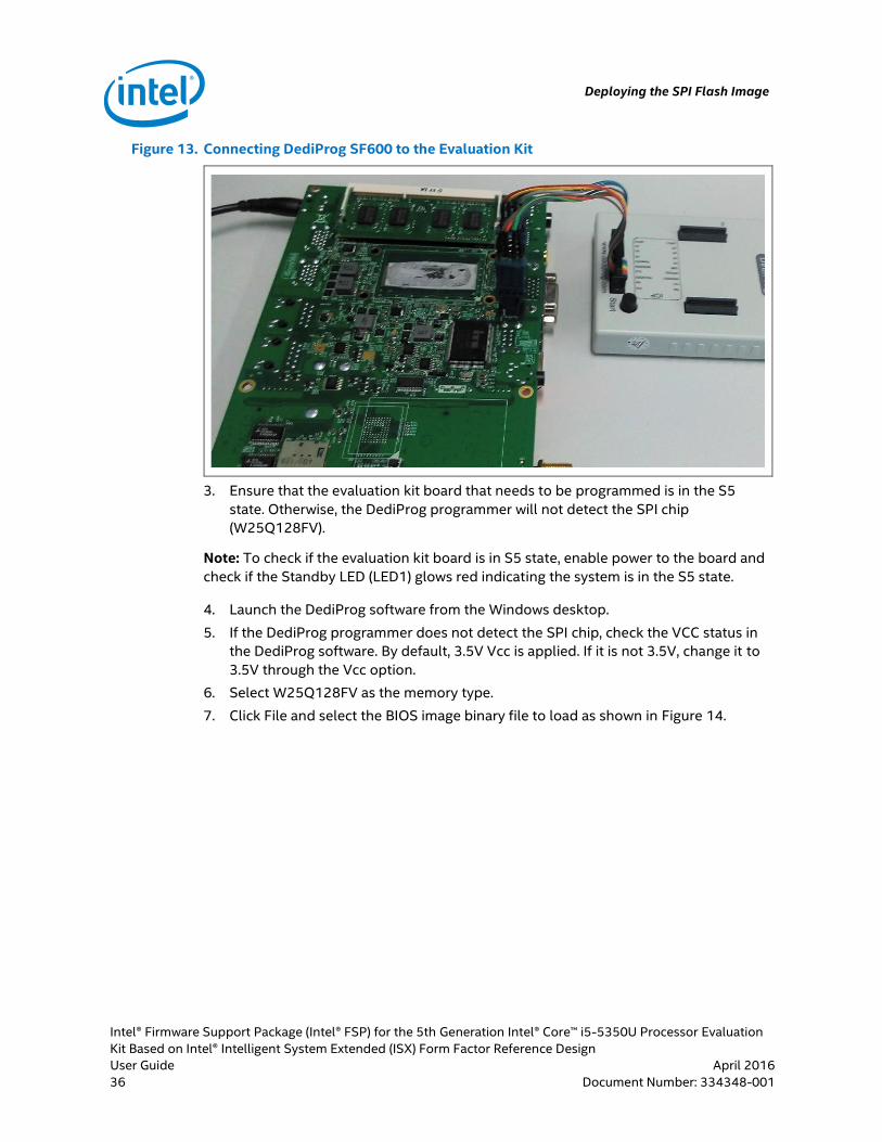
Figure 13. Connecting DediProg SF600 to the Evaluation Kit
3. Ensure that the evaluation kit board that needs to be programmed is in the S5
state. Otherwise, the DediProg programmer will not detect the SPI chip
(W25Q128FV).
Note: To check if the evaluation kit board is in S5 state, enable power to the board and
check if the Standby LED (LED1) glows red indicating the system is in the S5 state.
4. Launch the DediProg software from the Windows desktop.
5. If the DediProg programmer does not detect the SPI chip, check the VCC status in
the DediProg software. By default, 3.5V Vcc is applied. If it is not 3.5V, change it to
3.5V through the Vcc option.
6. Select W25Q128FV as the memory type.
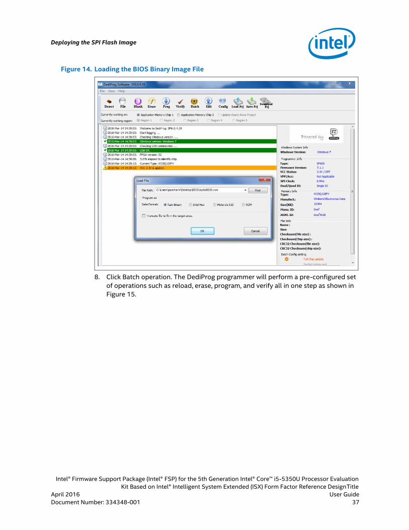
7. Click File and select the BIOS image binary file to load as shown in Figure 14.
Deploying the SPI Flash Image
Intel® Firmware Support Package (Intel® FSP) for the 5th Generation Intel® Core™ i5-5350U Processor Evaluation
Kit Based on Intel® Intelligent System Extended (ISX) Form Factor Reference DesignTitle
April 2016 User Guide
Document Number: 334348-001 Classification 37
Figure 14. Loading the BIOS Binary Image File
8. Click Batch operation. The DediProg programmer will perform a pre-configured set
of operations such as reload, erase, program, and verify all in one step as shown in
Figure 15.

Deploying the SPI Flash Image
Intel® Firmware Support Package (Intel® FSP) for the 5th Generation Intel® Core™ i5-5350U Processor Evaluation
Kit Based on Intel® Intelligent System Extended (ISX) Form Factor Reference Design
User Guide April 2016
38 Classification Document Number: 334348-001
Figure 15. DediProg Batch Operation
9. Remove the power from the evaluation kit board and unplug the DediProg
connector.
3.3.2 Flashrom Utility (Linux)
Flashrom is a Linux OS (Ubuntu) based utility used for identifying, reading, writing,
verifying, and erasing flash chips.
STEPS:
1. Install Linux OS (Ubuntu) on the evaluation kit.
2. Download the Flashrom utility from https://flashrom.org/Downloads and install it
on the evaluation kit.
3. Compile the flashrom, dependent packages (pciutils, zlib, libftdi, libusb), and build-
essential packages (gcc, make, etc.) using the below commands.
$ tar -xvf flashrom-0.9.8.tar.bz2
$ cd flashrom-0.9.8
$ make all
4. Use the command below to flash the BIOS image (16MB).
/flashrom-0.9.8$ sudo ./flashrom -w AptioBIOS.bin -p
internal:laptop=force_I_want_a_brick --VVV
§
Customized coreboot: Booting and Installing the Operating System
Intel® Firmware Support Package (Intel® FSP) for the 5th Generation Intel® Core™ i5-5350U Processor Evaluation
Kit Based on Intel® Intelligent System Extended (ISX) Form Factor Reference DesignTitle
April 2016 User Guide
Document Number: 334348-001 Classification 39
4.0 Customized coreboot: Booting and Installing
the Operating System
Once the customized coreboot in the SPI flash image has been flashed on the
evaluation kit, it can then be booted to install the OS. The procedure below describes
the installation of the Ubuntu OS on the evaluation kit.
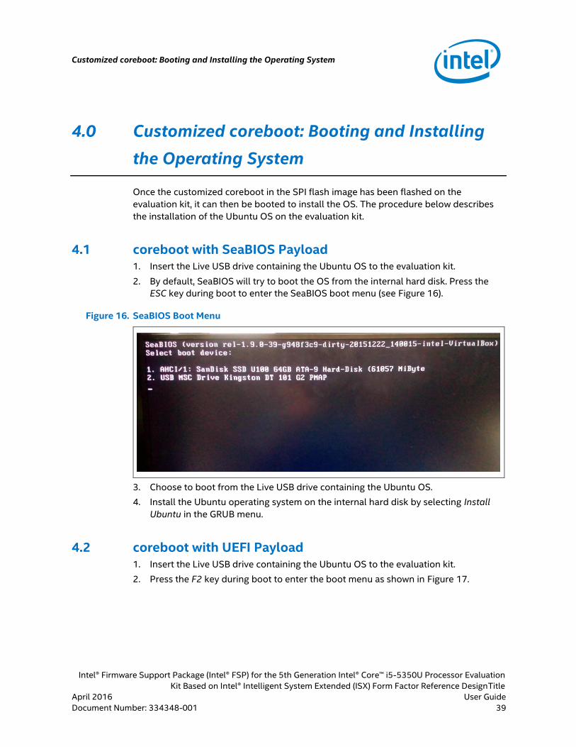
4.1 coreboot with SeaBIOS Payload 1. Insert the Live USB drive containing the Ubuntu OS to the evaluation kit.
2. By default, SeaBIOS will try to boot the OS from the internal hard disk. Press the
ESC key during boot to enter the SeaBIOS boot menu (see Figure 16).
Figure 16. SeaBIOS Boot Menu
3. Choose to boot from the Live USB drive containing the Ubuntu OS.
4. Install the Ubuntu operating system on the internal hard disk by selecting Install
Ubuntu in the GRUB menu.
4.2 coreboot with UEFI Payload 1. Insert the Live USB drive containing the Ubuntu OS to the evaluation kit.
2. Press the F2 key during boot to enter the boot menu as shown in Figure 17.

Customized coreboot: Booting and Installing the Operating System
Intel® Firmware Support Package (Intel® FSP) for the 5th Generation Intel® Core™ i5-5350U Processor Evaluation
Kit Based on Intel® Intelligent System Extended (ISX) Form Factor Reference Design
User Guide April 2016
40 Classification Document Number: 334348-001
Figure 17. UEFI Setup Menu
3. Choose to boot from Live USB drive as shown in Figure 18.
Figure 18. UEFI Boot Menu
4. Install the Ubuntu operating system on the internal hard disk by selecting Install
Ubuntu in the GRUB menu.
5. After installation, you may encounter the following error when booting Ubuntu
from the internal hard disk.
Uefi PatformBdsBootFail
Boot Failed EFI Hard Drive

Customized coreboot: Booting and Installing the Operating System
Intel® Firmware Support Package (Intel® FSP) for the 5th Generation Intel® Core™ i5-5350U Processor Evaluation
Kit Based on Intel® Intelligent System Extended (ISX) Form Factor Reference DesignTitle
April 2016 User Guide
Document Number: 334348-001 Classification 41
6. This shows that the UEFI has failed to locate the Ubuntu GRUB bootloader binary.
UEFI will try to search for the GRUB bootloader in the default location i.e. /EFI/
BOOT in the Ubuntu file system.
7. An alternative solution is to first boot from the Live USB and selecting Try Ubuntu
without installing in the GRUB menu. In the Ubuntu terminal, mount the first
partition of the internal hard disk and copy the /EFI/ubuntu directory to EFI/boot
using the following commands.
$ mkdir sda1
$ sudo mount /dev/sda1 sda1
$ cd sda1 && ls
EFI
$ sudo cp -rf EFI/ubuntu EFI/boot
$ cd EFI/boot && ls
grub.cfg grubx64.efi MokManager.efi shimx64.efi
$ cp -rf grubx64.efi bootx64.efi
$ ls
bootx64.efi grub.cfg grubx64.efi MokManager.efi shimx64.efi
8. Reboot the system to boot Ubuntu from the internal hard drive as shown in
Figure 19.
Figure 19. Ubuntu Operating System
Customized coreboot: Booting and Installing the Operating System
Intel® Firmware Support Package (Intel® FSP) for the 5th Generation Intel® Core™ i5-5350U Processor Evaluation
Kit Based on Intel® Intelligent System Extended (ISX) Form Factor Reference Design
User Guide April 2016
42 Classification Document Number: 334348-001
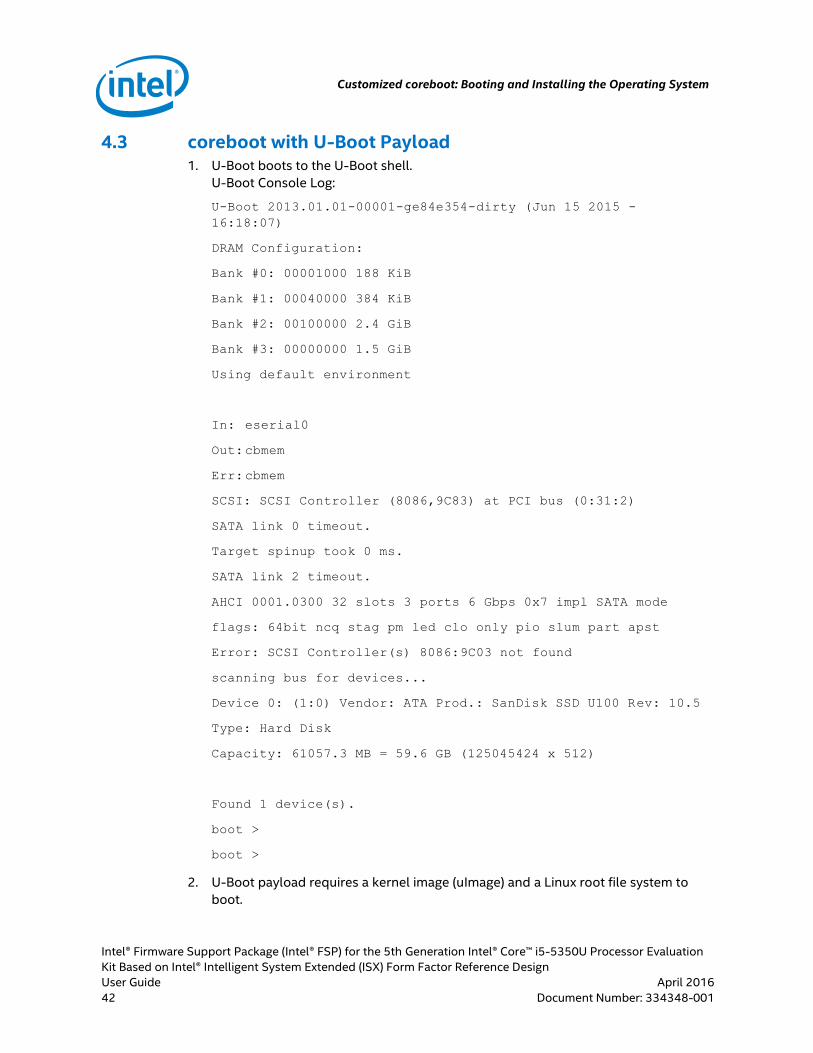
4.3 coreboot with U-Boot Payload 1. U-Boot boots to the U-Boot shell.
U-Boot Console Log:
U-Boot 2013.01.01-00001-ge84e354-dirty (Jun 15 2015 -
16:18:07)
DRAM Configuration:
Bank #0: 00001000 188 KiB
Bank #1: 00040000 384 KiB
Bank #2: 00100000 2.4 GiB
Bank #3: 00000000 1.5 GiB
Using default environment
In: eserial0
Out: cbmem
Err: cbmem
SCSI: SCSI Controller (8086,9C83) at PCI bus (0:31:2)
SATA link 0 timeout.
Target spinup took 0 ms.
SATA link 2 timeout.
AHCI 0001.0300 32 slots 3 ports 6 Gbps 0x7 impl SATA mode
flags: 64bit ncq stag pm led clo only pio slum part apst
Error: SCSI Controller(s) 8086:9C03 not found
scanning bus for devices...
Device 0: (1:0) Vendor: ATA Prod.: SanDisk SSD U100 Rev: 10.5
Type: Hard Disk
Capacity: 61057.3 MB = 59.6 GB (125045424 x 512)
Found 1 device(s).
boot >
boot >
2. U-Boot payload requires a kernel image (uImage) and a Linux root file system to
boot.
Customized coreboot: Booting and Installing the Operating System
Intel® Firmware Support Package (Intel® FSP) for the 5th Generation Intel® Core™ i5-5350U Processor Evaluation
Kit Based on Intel® Intelligent System Extended (ISX) Form Factor Reference DesignTitle
April 2016 User Guide
Document Number: 334348-001 Classification 43
Note: In Whitetip Mountain 1 CRB board, the Wind River Linux 5 has been verified to
boot from the SATA port or USB 2.0 port.
§
coreboot Debugging Methods
Intel® Firmware Support Package (Intel® FSP) for the 5th Generation Intel® Core™ i5-5350U Processor Evaluation
Kit Based on Intel® Intelligent System Extended (ISX) Form Factor Reference Design
User Guide April 2016
44 Classification Document Number: 334348-001
5.0 coreboot Debugging Methods
There are a number of troubleshooting and debugging methods for coreboot. Before
initializing the RAM, coreboot initializes the serial port (addressing cache and registers
only), so that debug text can be sent to a connected terminal. It can also send byte
codes to port 0x80 that are displayed on a two-hex-digit display of a connected POST
card.
The following describes the procedure to debug coreboot using Post Codes and Serial
Debug methods.
5.1 Post Codes
Post Codes is the earliest debug information available from coreboot on port 80h.
Many CRBs today have integrated Post Code hardware to display the debug
information on a two-hex-digit display.
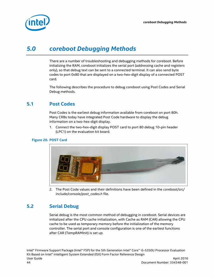
1. Connect the two-hex-digit display POST card to port 80 debug 10-pin header
(LPC1) on the evaluation kit board.
Figure 20. POST Card
2. The Post Code values and their definitions have been defined in the coreboot/src/
include/console/post_codes.h file.
5.2 Serial Debug
Serial debug is the most common method of debugging in coreboot. Serial devices are
initialized after the CPU cache initialization, with Cache as RAM (CAR) allowing the CPU
cache to be used as temporary memory before the initialization of the memory
controller. The serial port and console configuration is one of the earliest functions
after CAR (TempRAMInit) is set up.
coreboot Debugging Methods
Intel® Firmware Support Package (Intel® FSP) for the 5th Generation Intel® Core™ i5-5350U Processor Evaluation
Kit Based on Intel® Intelligent System Extended (ISX) Form Factor Reference DesignTitle
April 2016 User Guide
Document Number: 334348-001 Classification 45
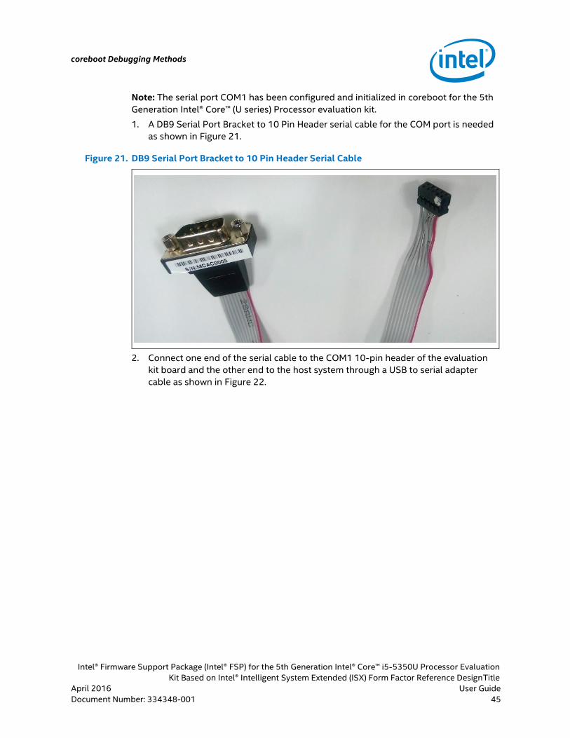
Note: The serial port COM1 has been configured and initialized in coreboot for the 5th
Generation Intel® Core™ (U series) Processor evaluation kit.
1. A DB9 Serial Port Bracket to 10 Pin Header serial cable for the COM port is needed
as shown in Figure 21.
Figure 21. DB9 Serial Port Bracket to 10 Pin Header Serial Cable
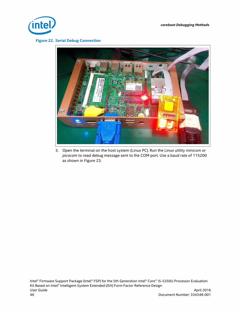
2. Connect one end of the serial cable to the COM1 10-pin header of the evaluation
kit board and the other end to the host system through a USB to serial adapter
cable as shown in Figure 22.
coreboot Debugging Methods
Intel® Firmware Support Package (Intel® FSP) for the 5th Generation Intel® Core™ i5-5350U Processor Evaluation
Kit Based on Intel® Intelligent System Extended (ISX) Form Factor Reference Design
User Guide April 2016
46 Classification Document Number: 334348-001
Figure 22. Serial Debug Connection
3. Open the terminal on the host system (Linux PC). Run the Linux utility minicom or
picocom to read debug message sent to the COM port. Use a baud rate of 115200
as shown in Figure 23.

coreboot Debugging Methods
Intel® Firmware Support Package (Intel® FSP) for the 5th Generation Intel® Core™ i5-5350U Processor Evaluation
Kit Based on Intel® Intelligent System Extended (ISX) Form Factor Reference DesignTitle
April 2016 User Guide
Document Number: 334348-001 Classification 47
Figure 23. Picocom Utility
§