fsm assy 031118€¦ · · 2018-03-11± 5 . rkp uhvlvwru eurzq eodfn rudqjh jrog ± 5 rkp...
TRANSCRIPT

Page 1 of 6 fsm_assy_031118.pdf
QRPGuys Digital Field Strength Meter
First, familiarize yourself with the parts and check for all the components. If a part is missing, please contact us and we will send one. You must use [email protected] to request a part. This kit contains an SMD component, the AD8307 IC. This requires a different skill set than through hole components. It is smaller than most through hole components. These instructions assume you know how to assemble surface mount technology components. Parts List 1 – QRPGuys Digital Field Strength Meter pcb 1 – U1, AD8307 SOP-8 case SMD logarithmic detector/amplifier 1 – U2, LM358 DIP Op Amp 1 – U3, 78L05 5v voltage regulator 1 – D1, clear lens green LED diode 2 – D2,3, 1N4148 diode, small glass diode with black band on one end 5 – C1,2,3,4,5, .1uF capacitor, marked 104 1 – C6, .001uF capacitor, marked 102 1 – R1, 10K ohm resistor (brown-black-orange-gold) 1 – R2, 10 ohm resistor (brown-black-black-gold) 1 – R3, 6.8K ohm resistor (green-gray-red-gold) 1 – R4, 2.2K ohm resistor (red-red-red-gold) 1 – R5, 51 ohm resistor (green-brown-black-gold) 1 – R6, 100K 9mm vertical pot 1 – S1, SPDT slide switch 1 – S2, vertical mount, tactile switch 1 – 100V 3 digit led voltmeter 1 – 8 pin DIP socket 2 – 2-56 x.31”L SS pan head screw 2 – 2-56 SS nut 2 - plastic spacer, #2 x .125”L x .19” dia.

Page 2 of 6 fsm_assy_031118.pdf
1 – “+” 9V battery clip – female 1 – “-“ 9V battery clip – male 1 – 2” piece of #30awg wirewrap wire 1 - 1/2”x1” red mylar filter 1 – J2, RP-SMA vert. pcb connector 1 – J1, BNC horz. pcb connector 1 – RP_SMA female stub antenna 4 – self adhesive rubber foot Start with the smallest components first, using the figure below as a guide. All the components mount on the top side, with exception of the four rubber feet.
[ ] Install U1, AD8307 IC observing the pin 1 location. Pin 1 is designated as the pin closest to the dot on top, or the corner pin of the side of the chip with the angled flat. If the leads appear to be tarnished it might be helpful to lightly scrape the tops and bottoms with an xacto knife.
Tin the #1 pin on the IC and position it over the pads. Hold it down with your finger and tack the #1 pin to the pad. Check the alignment and adjust if necessary by reheating the single pin. When you are satisfied lightly solder the remaining pins. Use SolderWick if you bridge any of the connections.

Page 3 of 6 fsm_assy_031118.pdf
[ ] Install D2,3, 1N4148 diode, small glass diode with black band on one end. Match the black banded
end with the silkscreen. [ ] Install C1,2,3,4,5, .1uF capacitor, marked 104 [ ] Install C6, .001uF capacitor, marked 102 [ ] Install R1, 10K ohm resistor (brown-black-orange-gold) [ ] Install R2, 10 ohm resistor (brown-black-black-gold) [ ] Install R3, 6.8K ohm resistor (green-gray-red-gold) [ ] Install R4, 2.2K ohm resistor (red-red-red-gold) [ ] Install R5, 51 ohm resistor (green-brown-black-gold) [ ] Install the 8 pin DIP socket, put the socket notch matching the silkscreen. [ ] Install D1, LED diode, the long pin is “positive” and must match with the silkscreen “+”. [ ] Install U3, 78L05 5v voltage regulator, observe the silkscreened outline. [ ] Install J2, RP-SMA vert. pcb connector, solder all pins. [ ] Install the “+” 9V battery clip – female [ ] Install the “-“ 9V battery clip – male [ ] Install S1, SPDT slide switch [ ] Install S2, vertical mount, tactile switch
Page 4 of 6 fsm_assy_031118.pdf
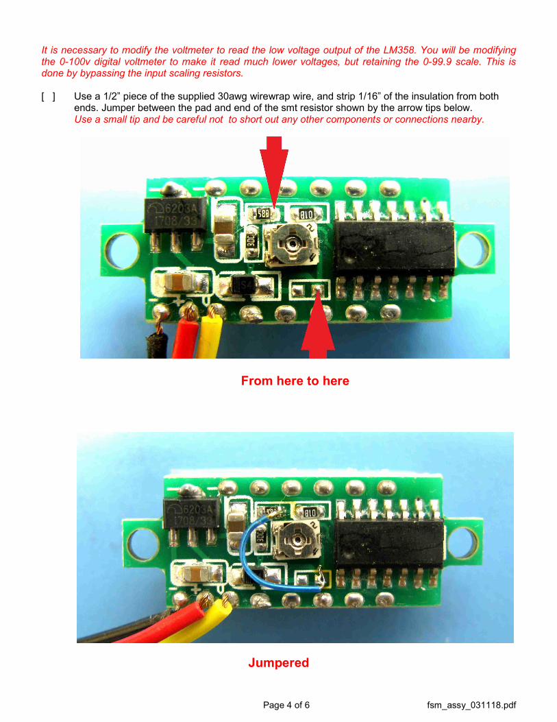
It is necessary to modify the voltmeter to read the low voltage output of the LM358. You will be modifying the 0-100v digital voltmeter to make it read much lower voltages, but retaining the 0-99.9 scale. This is done by bypassing the input scaling resistors. [ ] Use a 1/2” piece of the supplied 30awg wirewrap wire, and strip 1/16” of the insulation from both
ends. Jumper between the pad and end of the smt resistor shown by the arrow tips below. Use a small tip and be careful not to short out any other components or connections nearby.
From here to here
Jumpered

Page 5 of 6 fsm_assy_031118.pdf
[ ] Prepare the three wires of the digital voltmeter by cutting them 1/2” long. Strip off the insulation, and twist together any of the loose strands, and tin the leads as shown in the picture below.
[ ] Feed the three wires through the pcb at pads #1, #2, #3, and mount the digital voltmeter using the 2-56 hardware and nylon spacers as shown in the figure below. Then solder the three wires.
[ ] Cut the piece of red mylar to the same size as the face of the led voltmeter and carefully glue it to the face of the display. A tiny spec of superglue is all that is needed in the four corners. [ ] Install J1, BNC horz. pcb connector flush with the pcb. [ ] Install R6, 100K 9mm vertical pot. [ ] Install the LM358 DIP Op Amp in the DIP socket, be sure to observe Pin 1.
[ ] Apply the four self-adhesive silicone rubber feet to the bottom of the board as shown on the
backside silkscreen.
[ ] Install a 9V alkaline battery. This completes the assembly.

Page 6 of 6 fsm_assy_031118.pdf
Usage: Our Digital Field Strength Meter is a very sensitive device used to indicate an RF signal level over a wide range of frequencies, and power levels. The dynamic range should be more than 80 dBm. The maximum RF input level is +16 dBm (1.41 volts). This device should not be used as an RF power meter. The input is protected but limit your measurements to +10dBm or below to avoid damaging the AD8307. You should be able to detect signals down to -80 dBm (.01nW). Due to the internal modification of the digital voltmeter to increase the sensitivity, the reading on the digital voltmeter is only to be used as a relative indicator of RF signal strength. The ARRL handbook details many uses of the field strength meter. The internet is also an excellent source for uses of the field strength meter. http://www.eham.net/ehamforum/smf/index.php?topic=66691.0 We also see use of this device as an RF probe for troubleshooting signal flow thru circuits. The sensitivity is equal to our discontinued RF Probe, and the BNC input jack is a perfect point to connect a scope probe for this use. The ARRL has some excellent general uses and other troubleshooting tips on their on-line .pdf, pages 1.16-1.17. http://www.arrl.org/files/file/Product%20Notes/chapter_1.pdf Schematic:
Notes: __________________________________________________________________________________________________________________________________________________________________________________________________________________________________________________________________________________________________