front panel component systems - pentairprotect.com panel component system schroff.pentair.co.uk...
TRANSCRIPT

Front Panel Component Systems

ELECTRONICS PROTECTIONSCHROFF PRODUCT CATALOG 05/2018nVent.com/SCHROFF
Front panel component system
|11.12
OVERVIEW
MAIN KATALOG
Cabinets . . . . . . . 1
Wall mounted cases . . . . . . . . . 2
Accessories forcabinets and wallmounted cases . . 3
Climate control . . 4
Electronics cases . . . . . . . . . 5
Subracks/ 19" chassis . . . . . 6
Front panels, plug-in units . . . . 7
Systems . . . . . . . 8
Power supply units . . . . . . . . . . 9
Backplanes . . . . 10
Connectors, front panel component system . . . . . . . 11
Appendix . . . . . 12
Front panel component systemMain Catalogue
05092001
05092004 05092008 05092002
Components are pre-mounted in plastic bodies that can be arranged in rows; horizontal grid (3 planes) and vertical grid (8 or 16 planes)
A mounting frame with integrated PCB bracket fixes the front elements and forms the mechanical link between PCB, front elements and front panel
Front element system in use
STANDARDS • IEC 60297-3-101
IEC 60603 (DIN 41494 part 8)

Front panel component systemOVERVIEW
11.13nVent.com/SCHROFF |
Front panel component systemMain Catalogue
OPERATING AND DISPLAY ELEMENTS FOR FRONT PANELS
• Pre-assembled front element components
• Mounting frames with integrated PCB brackets
• Assembled front elements can be soldered in one step
• Subsequent front panel mounting
05092009 05092005
LEDs (light-emitting diodes) Test and make-break sockets
05092007 05092006
Potentiometers Fuse holders
05092008
Mounting frames with integrated PCB brackets
Overview . . . . . . 11.12
Front panel component systemSingle LEDs . . . . . . 11.14Double LEDs . . . . . 11.16Technical data LEDs . . . . . . . . . . . . 11.17Test sockets . . . . . 11.18Make-break socket. 11.19Technical data for test and make-break sockets and fuse holders . . . . . 11.20
Potentiometers . . 11.21Mounting frames . 11.22Drilling template . 11.23Design aids . . . . . . 11.24
SCHROFF PRODUCT CATALOG 05/201811.14 nVent.com/SCHROFF
Front panel component system
|
A3-195
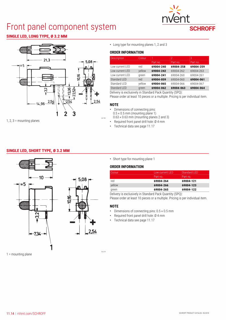
1, 2, 3 = mounting planes
Front panel component systemMain CataloguePart number in bold face type: ready for despatch within 2 working daysPart number in normal type: ready for despatch within 10 working days
• Long type for mounting planes 1, 2 and 3
ORDER INFORMATION
Delivery is exclusively in Standard Pack Quantity (SPQ): Please order at least 10 pieces or a multiple. Pricing is per individual item.
NOTE• Dimensions of connecting pins:
0.5 × 0.5 mm (mounting plane 1)0.63 × 0.63 mm (mounting planes 2 and 3)
• Required front panel drill hole: Ø 4 mm• Technical data see page 11.17
A3-214
1 = mounting plane
Front panel component system
• Short type for mounting plane 1
ORDER INFORMATION
Delivery is exclusively in Standard Pack Quantity (SPQ): Please order at least 10 pieces or a multiple. Pricing is per individual item.
NOTE• Dimensions of connecting pins: 0.5 × 0.5 mm• Required front panel drill hole: Ø 4 mm• Technical data see page 11.17
SINGLE LED, LONG TYPE, Ø 3.2 MM
Description Colour 1 2 3Part no. Part no. Part no.
Low current LED red 69004-240 69004-258 69004-259Low current LED yellow 69004-242 69004-262 69004-263Low current LED green 69004-241 69004-260 69004-261Standard LED red 69004-059 69004-060 69004-061Standard LED yellow 69004-065 69004-066 69004-067Standard LED green 69004-062 69004-063 69004-064
SINGLE LED, SHORT TYPE, Ø 3.2 MM
Colour Low current LED Standard LEDPart no. Part no.
red 69004-264 69004-121yellow 69004-266 69004-123green 69004-265 69004-122

11.15
Front panel component system
nVent.com/SCHROFF |Part number in bold face type: ready for despatch within 2 working daysPart number in normal type: ready for despatch within 10 working days
A1-194
1, 2, 3 = mounting plane
Front panel component system
• Long type for mounting plane 1, 2 and 3
ORDER INFORMATION
Delivery is exclusively in Standard Pack Quantity (SPQ): Please order at least 10 pieces or a multiple. Pricing is per individual item.
NOTE• Dimensions of connecting pins:
0.5 × 0.5 mm (mounting plane 1)0.63 × 0.63 mm (mounting planes 2 and 3)
• Required front panel drill hole: Ø 8 mm• Technical data see page 11.17
SINGLE LED, LONG TYPE, Ø 5 MM
Description Colour 1 2 3Part no. Part no. Part no.
Low current LED red 69004-250 69004-251 69004-252Low current LED yellow 69004-249 69004-256 69004-257Low current LED green 69004-253 69004-254 69004-255Standard LED red 69004-050 69004-051 69004-052Standard LED yellow 69004-056 69004-057 69004-058Standard LED green 69004-053 69004-054 69004-055

SCHROFF PRODUCT CATALOG 05/201811.16 nVent.com/SCHROFF
Front panel component system
|
A3-196
1, 2 = mounting plane
Front panel component system
• Long type for mounting plane 1 and 2
ORDER INFORMATION
Delivery is exclusively in Standard Pack Quantity (SPQ): Please order at least 10 pieces or a multiple. Pricing is per individual item.
NOTE• Dimensions of connecting pins: 0.63 × 0.63 mm• Required front panel drill hole: Ø 4 mm• Technical data see page 11.17
A3-217
1 = mounting plane
Front panel component system
• Short type for mounting plane 1
ORDER INFORMATION
Delivery is exclusively in Standard Pack Quantity (SPQ): Please order at least 10 pieces or a multiple. Pricing is per individual item.
NOTE• Dimensions of connecting pins: 0.5 × 0.5 mm• Required front panel drill hole: Ø 4 mm• Technical data see page 11.17
DOUBLE LED, LONG TYPE, Ø 3.2 MM
Description Colour 1 2Part no. Part no.
Low current LED red/red (Y/Z) 69004-274 69004-275Low current LED green/green (Y/Z) 69004-276 69004-277Low current LED yellow/yellow (Y/Z) 69004-278 69004-279Low current LED red/green (Y/Z) 69004-280 69004-281Low current LED red/yellow (Y/Z) 69004-282 –Low current LED yellow/green (Y/Z) 69004-284 –Standard LED red/red (Y/Z) 69004-068 69004-069Standard LED green/green (Y/Z) 69004-071 69004-072Standard LED yellow/yellow (Y/Z) 69004-074 69004-075Standard LED red/green (Y/Z) 69004-077 69004-078Standard LED red/yellow (Y/Z) 69004-080 –Standard LED yellow/green (Y/Z) 69004-083 –
DOUBLE LED, SHORT TYPE, Ø 3.2 MM
Colour Low current LED Standard LEDPart no. Part no.
red/red (Y/Z) 69004-286 69004-124yellow/yellow (Y/Z) 69004-288 69004-126green/green (Y/Z) 69004-287 69004-125red/green (Y/Z) 69004-289 69004-127red/yellow (Y/Z) 69004-290 69004-128yellow/green (Y/Z) 69004-291 69004-129

11.17
Front panel component system
nVent.com/SCHROFF |Part number in bold face type: ready for despatch within 2 working daysPart number in normal type: ready for despatch within 10 working days
\
A = standard LEDB = low current LED
1) The low current LEDs can be used from 2 to 20 mA (without reduction of lifespan), which means that a significantly higher luminosity can be achieved.
DIMENSIONS LEDS
Absolute maximum dataTa = 25 °C
A B A B A B A B A B A Bred, Ø 3.2 mm red, Ø 5 mm yellow, Ø 3.2 mm yellow, Ø 5 mm green, Ø 3.2 mm green, Ø 5 mm
Reverse voltage V 5 3 5 3 5 3 5 3 5 3 5 3On-state current mA 25 30 25 30 25 30 25 30 25 30 25 30Power dissipation mW 100 75 100 75 100 75 100 75 100 75 100 75Forward current mA(t < 10 µs)
100 75 100 75 100 75 100 75 100 75 100 75
Forward voltage V– type (10 mA/2 mA)
2.1 2.1 2.1 2.1 2.1 2.2 2.1 2.2 2.1 2.2 2.1 2.2
– max. (10 mA/2 mA) 3 3 3 3 3 3 3 3 3 3 3 3Luminous intensity mcd– at 2 mA
– 1.5 – 3.1 – 1.4 – 3.2 – 2 – 3.3
– at 10 mA 1) 1.8 13.4 2.2 25.1 2.7 13.4 3.4 28.6 3.2 24.6 3.9 25.7– at 20 mA 1) 3.6 26.8 4.4 48.2 5.4 28.7 6.8 60.8 6.4 54.9 7.8 54.6Wavelength nm(10 mA/2 mA)
635 650 635 650 585 585 585 585 565 563 565 563
Thermal resistance °C/W 400 470 350 390 400 470 350 390 400 470 350 390Angle of reflected beam � 50°Storage temperature –55 ... +100 °COperating temperature –55 ... +100 °C (low-current LED)/–40 ... +85 °C (Standard-LED)Solder temperature 260 °C/max. 5 sec (processing advice for wave soldering: protect plastic body against solder wave)Insulating body PBT (Crastin)Flammability of insulation body UL 94 V-0

SCHROFF PRODUCT CATALOG 05/201811.18 nVent.com/SCHROFF
Front panel component system
|
Long type
A3-199b
1, 2, 3 = mounting plane
Short type
KA943
1 = mounting plane
Front panel component system
• Long type for mounting plane 1, 2 and 3
• Short type for mounting plane 1
ORDER INFORMATION
Delivery is exclusively in Standard Pack Quantity (SPQ): Please order at least 10 pieces or a multiple. Pricing is per individual item.
NOTE• Dimensions of connecting pins: 0.3 × 0.6 mm• Required front panel drill hole: Ø 4 mm• Technical data see page 11.20
Long type
05009050
1, 2, 3 = mounting plane
Short type
05009051
1 = mounting plane
Front panel component system
• Long type for mounting plane 1, 2 and 3
• Short type for mounting plane 1
ORDER INFORMATION
Delivery is exclusively in Standard Pack Quantity (SPQ): Please order at least 10 pieces or a multiple. Pricing is per individual item.
NOTE• Dimensions of connecting pins: 0.3 × 0.6 mm• Required front panel drill hole: Ø 4 mm• Technical data see page 11.20
TEST SOCKET, Ø 2 MM
For application in 1 2 3Part no. Part no. Part no.
Long type 69004-086 69004-087 69004-088Short type 69004-130 – –
DOUBLE TEST SOCKET, Ø 2 MM
For application in 1 2 3Part no. Part no. Part no.
Long type 69004-089 69004-090 69004-091Short type 69004-131 – –

11.19
Front panel component system
nVent.com/SCHROFF |Part number in bold face type: ready for despatch within 2 working daysPart number in normal type: ready for despatch within 10 working days
A3-200
1 = mounting plane
Front panel component system
• Long type for mounting plane 1
• Gold-plated contacts
• Can also be used as test socket
ORDER INFORMATION
Delivery is exclusively in Standard Pack Quantity (SPQ): Please order at least 10 pieces or a multiple. Pricing is per individual item.
NOTE• Dimensions of connecting pins: 0.3 × 0.6 mm• Required front panel drill hole: Ø 4 mm• Technical data see page 11.20
DOUBLE MAKE-BREAK SOCKET, Ø 2 MM
1
For application in Part no.Long type 69004-095

SCHROFF PRODUCT CATALOG 05/201811.20 nVent.com/SCHROFF
Front panel component system
|
A3-200a
Front panel component system
• Long type for mounting plane 1
• For glass fuse inserts 5 x 20 mm to DIN 41 571, 250 VAC, 6.3 A
• Contacts silver-plated
ORDER INFORMATION
Delivery is exclusively in Standard Pack Quantity (SPQ): Please order at least 10 pieces or a multiple. Pricing is per individual item.
NOTE• Dimensions of connecting pins: 0.7 × 0.6 mm• Required front panel drill hole: Ø 9 mm
\
FUSE HOLDER
Description Part no.Long type 69004-098
Test socket/make-break socket Double test socket/double make-break socket
Fuse holder
Operating voltage ≤ 60 VDC/AC ≤ 30 VAC ≤ 250 VACOperating current ≤ 1 A ≤ 1 A ≤ 6.3 ATest voltage 1 kV/50 Hz 1 kV/50 Hz –Temperature range –25 ... +70 °C –25 ... +70 °C –25 ... +70 °CSolder temperature 260 °C/max. 5 sec (processing advice for wave soldering: protect plastic body against solder wave)Contact material Copper alloy Copper alloy Copper alloyContact surface Selectively gold-plated Selectively gold-plated Silver-platedInsulating body PBT (Crastin) PBT (Crastin) PBT (Crastin)Climatic use category HSF 1) to DIN 40 040 HSF 1) to DIN 40 040 HSF 1) to DIN 40 040Flammability UL 94 V-0 UL 94 V-0 UL 94 V-01) H = –25 °C; S = +70 °C; F = 75 % air humidity, no condensation

11.21
Front panel component system
nVent.com/SCHROFF |Part number in bold face type: ready for despatch within 2 working daysPart number in normal type: ready for despatch within 10 working days
A3-275
Pins 1 and 2 low-ohmic when left-hinged; pins 2 and 3 low-ohmic when right-hinged
Front panel component system
• Short type for mounting plane 1
ORDER INFORMATION
Delivery is exclusively in Standard Pack Quantity (SPQ): Please order at least 10 pieces or a multiple. Pricing is per individual item.
TECHNICAL DATA
NOTE• Dimensions of connecting pins: 0.45 × 0.45 mm• Required front panel drill hole: Ø 8 mm• When left-hinged: pins 1 and 2 low-ohmic• When right-hinged: pins 2 and 3 low-ohmic
CERMET POTENTIOMETERS
Resistance Part no.kΩ1 69004-1695 69004-16520 69004-161100 69004-155
Operating voltage ≤ 200 VDC/ ACOperating current ≤ 100 mALoad capacity 0.5 Watt at Ta = 70 °CTest voltage 500 V/50 HzResistance tolerance � 10 %Electrical rotation angle 230° � 5°Insulation resistance change 100 MΩContact resistance change 3 Ω or 3 %, use largest valueTorque at initial turning 0.021 NmStorage temperature –55 ... +125 °COperating temperature –25 ... +70 °CService life (full rotation) 200 cyclesService life at 0.5 Watt load 1000 h at Ta = 70 °CSolder temperature 260 °C/max. 5 sec (processing advice for
wave soldering: protect plastic body against solder wave)
Insulating body PBT (Crastin)Flammability UL 94 V-0Resistance of gasket to cleaning 85 °C max. 1 min.Temperature coefficient � 100 ppm/K

SCHROFF PRODUCT CATALOG 05/201811.22 nVent.com/SCHROFF
Front panel component system
|
KA942a
Mounting frame for mounting plane 1
KA942b
Mounting frame for mounting planes 1 and 2
KA942c
Mounting frame for mounting planes 1, 2 and 3
Front panel component system
• With 2 threaded female connectors M 2.5
• Material PBT
• Flammability UL 94 V-0
ORDER INFORMATION
Delivery is exclusively in Standard Pack Quantity (SPQ): Please order at least 10 pieces or a multiple. Pricing is per individual item.
NOTE• Mounting frames nos. 69004-043, 69004-044 and 69004-045 cannot be
used in conjunction with the aluminium profile handle for front panels
MOUNTING FRAMES WITH PCB BRACKET FOR MOUNTING PLANES
Description Part no.Mounting frame for mounting plane 1 69004-043Mounting frame for mounting planes 1 and 2 69004-044Mounting frame for mounting planes 1, 2 and 3 69004-045

11.23
Front panel component system
nVent.com/SCHROFF |Part number in bold face type: ready for despatch within 2 working daysPart number in normal type: ready for despatch within 10 working days
KA942d
Mounting frame for mounting plane 1
Front panel component system
• With 2 grub screws for fixing on PCBs
• Board thickness max. 1.6 mm
• Drilled hole for fixing board max. 2.8 mm
ORDER INFORMATION
Delivery is exclusively in Standard Pack Quantity (SPQ): Please order at least 10 pieces or a multiple. Pricing is per individual item.
A4_276
Front panel component system
• Design aid for processing of front panels
ORDER INFORMATION
Delivery is exclusively in Standard Pack Quantity (SPQ): Please order at least 10 pieces or a multiple. Pricing is per individual item.
MOUNTING FRAME WITH PCB BRACKET FOR FRAME TYPE PLUG-IN UNITS
Description Part no.Support frame with board support for frame type plug-in units 69004-046
DRILLING TEMPLATE
Description Material Part no.Drilling template EPGC 02 (fibreglass reinforced Epoxy) 69004-042

SCHROFF PRODUCT CATALOG 05/201811.24 nVent.com/SCHROFF
Front panel component system
|
DESIGN AIDS
Conmponent side of PCB Front of front panel
1) PCB2) Component mounting limit
FEA45510 3) Front panel FEA45511
Placement example
E1 = first mounting planeE2 = second mounting plane E3 = third mounting plane
ELA40278
2)
1)3)
2 )

11.25
Front panel component system
nVent.com/SCHROFF |Part number in bold face type: ready for despatch within 2 working daysPart number in normal type: ready for despatch within 10 working days
Text
PCB tracks width min. 0.6 mmGrid 2.54 mm
DESIGN AIDS
PCB tracksView solder sideShort type LED, Ø 3.2 mm
Double LED,Ø 3.2 mm
View solder sideLong type LED,Ø 3.2 mm
Double LED,Ø 3.2 mm
A4_277a A4_277b A3_205a A3_205b
Test socket, Ø 2 mm
Double test socket, Ø 2 mm
LED, Ø 5 mm
Test socket, Ø 2 mm
A3_215a A3_215b A4_272 A3_205c
PotentiometerDouble test socket, Ø 2 mm
Make/break socket, Ø 2 mm
FEA45990 A4_273 A2_114a
Double make-break socket, Ø 2 mm
Fuse holder
A2_114b A2_114d
Dimensions of connecting pins
Recommended hole Ø
Solder eyes Ø
0.5 × 0.5 mm 1.0 mm � 0.05 2.1 mm � 0.10.63 × 0.63 mm 1.1 mm � 0.05 2.2 mm � 0.20.3 × 0.6 mm 0.9 mm � 0.05 2.0 mm � 0.20.7 × 0.6 mm 1.1 mm � 0.05 2.1 mm � 0.20.4 × 0.6 mm 0.9 mm � 0.05 2.0 mm � 0.2
0.45 × 0.45 mm 0.7 mm � 0.05 1.8 mm � 0.2

nVent.com/SCHROFF
©2018 nVent. All nVent marks and logos are owned or licensed by nVent Services GmbH or its affiliates. All other trademarks are the property of their respective owners. nVent reserves the right to change specifications without notice.
CADDY ERICO HOFFMAN RAYCHEM SCHROFF TRACEROur powerful portfolio of brands:
North AmericaWarwick, RI, USATel +1.800.525.4682
San Diego, CA, USATel +1.800.854.7086
Europe, Middle East & IndiaStraubenhardt, GermanyTel +49 7082 794 0
Betschdorf, FranceTel +33 3 88 90 64 90
Warsaw, PolandTel +48 22 209 98 35
Hemel Hempstead, Great BritainTel +44 1442 24 04 71
Lainate, ItalyTel +39 02 932 714 1
Dubai, United Arab EmiratesTel +971 4 37 81 700
Bangalore, IndiaTel +91 80 67152000
Istanbul, TurkeyTel +90 216 250 7374
Asia PacificShanghai, ChinaTel +86 21 2412 6943
SingaporeTel +65 6768 5800
Shin-Yokohama, JapanTel +81 45 476 0271