front mounted alternator bracket assembly inspection
TRANSCRIPT
CATEGORY 5
SIL15-8
TECHNICAL PORTIONS
FAA APPROVED
CONTINENTAL MOTORS® AIRCRAFT ENGINE
SERVICE INFORMATION LETTERContains Useful Information Pertaining To Your Aircraft Engine
SUBJECT: Front Mounted Alternator Bracket Assembly Inspection
PURPOSE: To provide inspection instructions for specific front mounted alternator bracket assembly (P/N 657046).
COMPLIANCE: During the next maintenance event and every 100-Hour/Annual Inspection, whichever may occur first for bracket (P/N) 657046, Revision A or earlier).
MODELSAFFECTED: IO360-ES and L/TSIO360-RB utilizing front mounted alternator bracket
assembly (P/N) 657046, Revision A or earlier)
I. GENERAL INFORMATION
Field reports indicate isolated instances of cracks found in the forward upper alternator mounting flange and crankcase mounting areas of the front mounted belt-driven alternator bracket assembly (Part Number (P/N) 657046, Revision A or earlier).
The belt-driven alternator bracket incorporates a pressed bushing designed to move when tightened. This movement is intended to absorb an allowable gap which may occur between the bushing and the alternator washer after achieving proper alignment of the belt-driven alternator to the bracket assembly. The maximum allowable gap was up to 0.032 inch with the previously provided washers.
Recent analysis and testing indicates the force required to move the bushing can be higher than the force required to bend the two upper mounting flanges to close the gap between the alternator boss and the upper bracket flanges.
II. SCOPE
Action required to comply with this bulletin:
1. Remove the front mounted belt-driven alternator and alternator bracket assembly (P/N 657046), 2. Visually inspect all surface areas of the bracket to determine serviceability, 3. Reinstall the alternator bracket assembly (P/N 657046) and the front mounted belt-driven alternator, if serviceable, or replace with a serviceable replacement, according to the enhanced instructions in this service document.
This Service Document reduces the maximum allowable gap to less than 0.010 inches and installs additional shims (P/N 658616-3, 0.010 inches) at the aft location of the alternator pivot bolt. Additional shims assist the alignment between the alternator sheave and drive sheave and fills the void between the alternator boss and the upper bracket assembly.
ISSUED REVISED
P.O. Box 90 Mobile, AL 251-436-8299
PAGE NO DOC NO REVISION
2015/11/30 1 of 6 SIL15-8 ©2015 Continental Motors, Inc.

III. INSPECTION
1. Remove the belt-driven alternator according to the instructions in the engine Maintenance and Overhaul Manual.
2. Inspect the alternator, drive sheave, brace, and bracket assembly for physical damage.
3. Perform a visual inspection using a minimum 10x magnifier and bright light source on the cast aluminum bracket to verify the areas surrounding the mounting lugs and pressed bushing are not cracked or fractured (see Figure 1).
a. If the components are serviceable, install the belt-driven alternator with new shims, washers and lock nut according to the instructions in Section IV, “BRACKET ASSEMBLY INSTALLATION,” on page 3.
b. If any of the removed components exhibit physical damage or the 10x visual inspection indicates the bracket assembly is cracked, obtain the necessary replacement parts and install according to the instructions in the primary ICA.
Figure 1. Bracket Assembly Inspection Area, typical
ISSUED REVISED
P.O. Box 90 Mobile, AL 251-436-8299
PAGE NO DOC NO REVISION
2015/11/30 2 of 6 SIL15-8
IV. BRACKET ASSEMBLY INSTALLATION
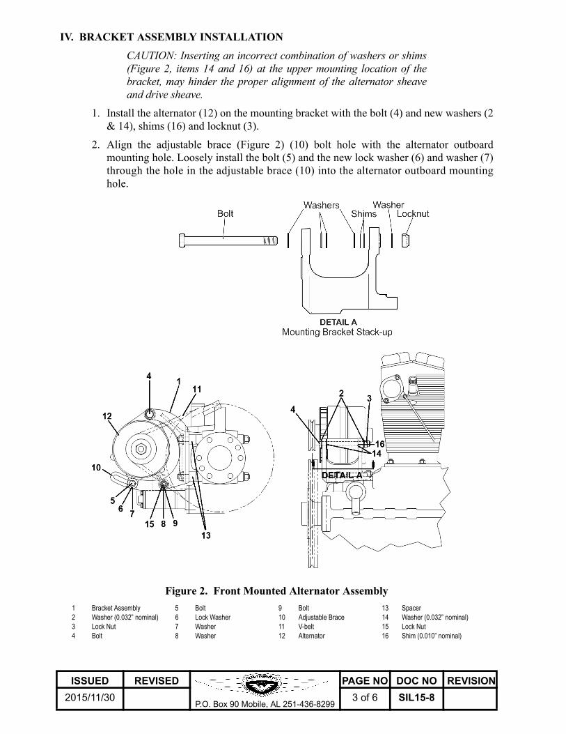
CAUTION: Inserting an incorrect combination of washers or shims (Figure 2, items 14 and 16) at the upper mounting location of the bracket, may hinder the proper alignment of the alternator sheave and drive sheave.
1. Install the alternator (12) on the mounting bracket with the bolt (4) and new washers (2 & 14), shims (16) and locknut (3).
2. Align the adjustable brace (Figure 2) (10) bolt hole with the alternator outboard mounting hole. Loosely install the bolt (5) and the new lock washer (6) and washer (7) through the hole in the adjustable brace (10) into the alternator outboard mounting hole.
.
Figure 2. Front Mounted Alternator Assembly
1 Bracket Assembly 5 Bolt 9 Bolt 13 Spacer2 Washer (0.032” nominal) 6 Lock Washer 10 Adjustable Brace 14 Washer (0.032” nominal)3 Lock Nut 7 Washer 11 V-belt 15 Lock Nut4 Bolt 8 Washer 12 Alternator 16 Shim (0.010” nominal)
ISSUED REVISED
P.O. Box 90 Mobile, AL 251-436-8299
PAGE NO DOC NO REVISION
2015/11/30 3 of 6 SIL15-8

3. Check the alignment of the alternator (12) sheave to the propeller flange sheave with a pulley alignment tool, (P/N 8082-IA, or equivalent, see Figure 3).
a. Place the alignment tool in the CENTER of the alternator sheave and lower the opposite end of the alignment tool into the channel of the drive sheave; aligning the center of the alternator sheave to the center of the drive sheave.
CAUTION: Each shim is nominally 0.010 inch. If the gap is greater than 0.010 inches, add a shim to fill the void.
b. If the pulley alignment tool indicates the sheaves are misaligned, remove the bolt (Figure 2) (4), washers (2 & 14), shims (16), and lock nut (3) from the alternator and bracket assembly (1) and use additional shims (16), as required, to fill the gap between the alternator and bracket assembly. When proper alignment between the two sheaves is achieved, proceed to next step.
c. With bolt (4) loose, fill any remaining void between the washer (Figure 2) (14) and the pressed bushing larger than 0.010 with shims (16) as needed.
Figure 3. Pulley Alignment Tool (P/N 8082-IA), typical
4. Inspect the V-belt (11) for cracks, abnormal wear, or frayed edges; replace if necessary.
5. Install V-belt (11) on propeller flange sheave and alternator (12) sheave.
6. Adjust the V-belt tension and complete the alternator installation according to the Alternator Drive Belt Tension Check and Adjustment instructions in your Maintenance and Overhaul Manual or airframe manufacturer’s instructions.
7. Connect the aircraft wiring harness to the alternator according to the aircraft maintenance manual.
8. Torque electrical connectors according to alternator manufacturer’s specifications.
9. Create an appropriate logbook entry detailing the compliance actions taken in accordance with this Service Document (SIL15-8).
ISSUED REVISED
P.O. Box 90 Mobile, AL 251-436-8299
PAGE NO DOC NO REVISION
2015/11/30 4 of 6 SIL15-8

V. WARRANTY
This Service Document is your authorization to perform the required inspections and receive warranty reimbursement, limited to the “Models Affected” and compliance action required as defined within.Contact your authorized Continental Motors distributor for warranty claim application and parts return instructions.
Contact Continental Motors Technical Services at one of the numbers listed below if you have any questions concerning the technical content of this Service Document.
1.888.826.5465 toll free in United States+1.251.436.8299 international callers+1.305.964.0872 en Español
NOTE: Visit the Continental Motors web site at www.continentalmotors.aero to obtain copies of Continental Motors Warranty Policies.
A. Allowances/Reimbursements
1. Bracket replacement labor allowance (if applicable, per Section III, “INSPECTION”, step 3, b): two hours at published shop rate.
2. Parts (if required, per Section III, “INSPECTION”, step 3, b):
NOTE: Inspect replacement alternator bracket part number - should be P/N 657046, Revision B or subsequent to avoid repeat inspection.
a. Bracket assembly; if required.
b. Washers
c. Lock Nut
d. Shims
B. Illustrated Parts Catalog Instructions
Replacement parts required to comply with this bulletin are published in the illustrated parts catalogs on the Continental Motors web site and may be ordered through any authorized Continental Motors distributor.
NOTE: To find an authorized Continental Motors distributor, follow this link: http://www.continentalmotors.aero/Support_Materials/Authorized_Distributor_Listing/
ISSUED REVISED
P.O. Box 90 Mobile, AL 251-436-8299
PAGE NO DOC NO REVISION
2015/11/30 5 of 6 SIL15-8

Intentionally Left Blank
ISSUED REVISED
P.O. Box 90 Mobile, AL 251-436-8299
PAGE NO DOC NO REVISION
2015/11/30 6 of 6 SIL15-8