front cover implementing vpns in a z/os environment · front cover implementing vpns in a z/os...
TRANSCRIPT
ibm.com/redbooks
Front cover
Implementing VPNs in a z/OS Environment
Bill WhiteRaoni Castro
Abdel-Razak IsbaihMakoto Kikuchi
Bernie Young
Planning and implementation guidance
Realistic examples and scenarios
Troubleshooting tips for common VPN problems


International Technical Support Organization
Implementing VPNs in a z/OS Environment
January 2002
SG24-6530-00

© Copyright International Business Machines Corporation 2002. All rights reserved.Note to U.S Government Users - Documentation related to restricted rights - Use, duplication or disclosure is subject to restrictions setforth in GSA ADP Schedule Contract with IBM Corp.
First Edition (January 2002)
This edition applies to Version 1 Release 2 of z/OS SecureWay Security Server, Program Number 5694-A01.
Comments may be addressed to:IBM Corporation, International Technical Support OrganizationDept. HYJ Mail Station P0992455 South RoadPoughkeepsie, NY 12601-5400
When you send information to IBM, you grant IBM a non-exclusive right to use or distribute the information in any way it believes appropriate without incurring any obligation to you.
Take Note! Before using this information and the product it supports, be sure to read the general information in “Special notices” on page 169.
Contents
Contents . . . . . . . . . . . . . . . . . . . . . . . . . . . . . . . . . . . . . . . . . . . . . . . . . . . . . . . . . . . . . . . . iii
Preface . . . . . . . . . . . . . . . . . . . . . . . . . . . . . . . . . . . . . . . . . . . . . . . . . . . . . . . . . . . . . . . . . viiThe team that wrote this redbook. . . . . . . . . . . . . . . . . . . . . . . . . . . . . . . . . . . . . . . . . . . . . . viiSpecial notice . . . . . . . . . . . . . . . . . . . . . . . . . . . . . . . . . . . . . . . . . . . . . . . . . . . . . . . . . . . . viiiIBM trademarks . . . . . . . . . . . . . . . . . . . . . . . . . . . . . . . . . . . . . . . . . . . . . . . . . . . . . . . . . . viiiComments welcome. . . . . . . . . . . . . . . . . . . . . . . . . . . . . . . . . . . . . . . . . . . . . . . . . . . . . . . viii
Chapter 1. What is VPN - a general overview . . . . . . . . . . . . . . . . . . . . . . . . . . . . . . . . . . 11.1 IPSec concept . . . . . . . . . . . . . . . . . . . . . . . . . . . . . . . . . . . . . . . . . . . . . . . . . . . . . . . . . 21.2 Authentication Header (AH) protocol . . . . . . . . . . . . . . . . . . . . . . . . . . . . . . . . . . . . . . . 31.3 Encapsulating Security Payload (ESP) protocol . . . . . . . . . . . . . . . . . . . . . . . . . . . . . . . 41.4 SA combinations . . . . . . . . . . . . . . . . . . . . . . . . . . . . . . . . . . . . . . . . . . . . . . . . . . . . . . . 51.5 Internet Key Exchange (IKE) protocol . . . . . . . . . . . . . . . . . . . . . . . . . . . . . . . . . . . . . . . 61.6 Layer 2 Tunneling Protocol (L2TP) . . . . . . . . . . . . . . . . . . . . . . . . . . . . . . . . . . . . . . . . . 81.7 Network Address Translation (NAT) . . . . . . . . . . . . . . . . . . . . . . . . . . . . . . . . . . . . . . . 12
Chapter 2. What is implemented in z/OS VPN . . . . . . . . . . . . . . . . . . . . . . . . . . . . . . . . 152.1 Manual tunnels and Dynamic tunnels . . . . . . . . . . . . . . . . . . . . . . . . . . . . . . . . . . . . . . 16
2.1.1 Manual tunnels . . . . . . . . . . . . . . . . . . . . . . . . . . . . . . . . . . . . . . . . . . . . . . . . . . . 162.1.2 Dynamic tunnels (ISAKMP). . . . . . . . . . . . . . . . . . . . . . . . . . . . . . . . . . . . . . . . . . 172.1.3 Manual and Dynamic tunnels: Summary of differences . . . . . . . . . . . . . . . . . . . . 17
2.2 IKE negotiation overview - Dynamic tunnel mode. . . . . . . . . . . . . . . . . . . . . . . . . . . . . 172.2.1 IKE Phase 1 Main mode with Signature Authentication . . . . . . . . . . . . . . . . . . . . 182.2.2 IKE Phase 1 Aggressive mode with Signature Authentication . . . . . . . . . . . . . . . 212.2.3 IKE Phase 2 negotiation . . . . . . . . . . . . . . . . . . . . . . . . . . . . . . . . . . . . . . . . . . . . 22
2.3 Know the difference – to make the best choice . . . . . . . . . . . . . . . . . . . . . . . . . . . . . . 232.3.1 Pre-shared key and RSA-based Signature . . . . . . . . . . . . . . . . . . . . . . . . . . . . . . 232.3.2 Diffie-Hellman groups . . . . . . . . . . . . . . . . . . . . . . . . . . . . . . . . . . . . . . . . . . . . . . 252.3.3 Initiator’s or Responder’s Session Maximum Key Lifetime . . . . . . . . . . . . . . . . . . 252.3.4 Initiator’s or Responder’s Session Maximum Size Limit . . . . . . . . . . . . . . . . . . . . 262.3.5 Hash algorithms . . . . . . . . . . . . . . . . . . . . . . . . . . . . . . . . . . . . . . . . . . . . . . . . . . 262.3.6 Authentication algorithms . . . . . . . . . . . . . . . . . . . . . . . . . . . . . . . . . . . . . . . . . . . 262.3.7 Encryption algorithms . . . . . . . . . . . . . . . . . . . . . . . . . . . . . . . . . . . . . . . . . . . . . . 262.3.8 Main mode and Aggressive mode. . . . . . . . . . . . . . . . . . . . . . . . . . . . . . . . . . . . . 272.3.9 Dynamic tunnel mode and Manual tunnel mode. . . . . . . . . . . . . . . . . . . . . . . . . . 272.3.10 Transport mode and Tunnel mode . . . . . . . . . . . . . . . . . . . . . . . . . . . . . . . . . . . 27
2.4 What is implemented in z/OS Firewall Technologies . . . . . . . . . . . . . . . . . . . . . . . . . . 272.4.1 IPSec RFCs . . . . . . . . . . . . . . . . . . . . . . . . . . . . . . . . . . . . . . . . . . . . . . . . . . . . . 282.4.2 IKE Phase 1 supported methods . . . . . . . . . . . . . . . . . . . . . . . . . . . . . . . . . . . . . 292.4.3 ESP protocol methods . . . . . . . . . . . . . . . . . . . . . . . . . . . . . . . . . . . . . . . . . . . . . 302.4.4 AH protocol methods . . . . . . . . . . . . . . . . . . . . . . . . . . . . . . . . . . . . . . . . . . . . . . 30
Chapter 3. VPN planning and design . . . . . . . . . . . . . . . . . . . . . . . . . . . . . . . . . . . . . . . 313.1 VPN planning and design considerations . . . . . . . . . . . . . . . . . . . . . . . . . . . . . . . . . . . 323.2 Data management planning flowchart. . . . . . . . . . . . . . . . . . . . . . . . . . . . . . . . . . . . . . 32
3.2.1 Topology . . . . . . . . . . . . . . . . . . . . . . . . . . . . . . . . . . . . . . . . . . . . . . . . . . . . . . . . 343.2.2 Tunnel endpoints same as data endpoints? . . . . . . . . . . . . . . . . . . . . . . . . . . . . . 403.2.3 Tunnel endpoints support dynamic tunnels?. . . . . . . . . . . . . . . . . . . . . . . . . . . . . 40
© Copyright IBM Corp. 2002 iii

3.2.4 Risk assessment . . . . . . . . . . . . . . . . . . . . . . . . . . . . . . . . . . . . . . . . . . . . . . . . . . 403.2.5 Encrypt . . . . . . . . . . . . . . . . . . . . . . . . . . . . . . . . . . . . . . . . . . . . . . . . . . . . . . . . . 423.2.6 Authenticate . . . . . . . . . . . . . . . . . . . . . . . . . . . . . . . . . . . . . . . . . . . . . . . . . . . . . 423.2.7 Protocol . . . . . . . . . . . . . . . . . . . . . . . . . . . . . . . . . . . . . . . . . . . . . . . . . . . . . . . . . 423.2.8 Cascading, nesting or mixed topology? . . . . . . . . . . . . . . . . . . . . . . . . . . . . . . . . 43
3.3 Key management planning flowchart . . . . . . . . . . . . . . . . . . . . . . . . . . . . . . . . . . . . . . 433.3.1 IKE mode . . . . . . . . . . . . . . . . . . . . . . . . . . . . . . . . . . . . . . . . . . . . . . . . . . . . . . . 443.3.2 Authentication method . . . . . . . . . . . . . . . . . . . . . . . . . . . . . . . . . . . . . . . . . . . . . 453.3.3 Assess risk . . . . . . . . . . . . . . . . . . . . . . . . . . . . . . . . . . . . . . . . . . . . . . . . . . . . . . 45
3.4 Common scenarios . . . . . . . . . . . . . . . . . . . . . . . . . . . . . . . . . . . . . . . . . . . . . . . . . . . . 463.4.1 Branch office connection. . . . . . . . . . . . . . . . . . . . . . . . . . . . . . . . . . . . . . . . . . . . 463.4.2 Business partner connection. . . . . . . . . . . . . . . . . . . . . . . . . . . . . . . . . . . . . . . . . 483.4.3 Remote user connection . . . . . . . . . . . . . . . . . . . . . . . . . . . . . . . . . . . . . . . . . . . . 49
Chapter 4. VPN pre-installation and implementaion . . . . . . . . . . . . . . . . . . . . . . . . . . . 514.1 Configuring the z/OS firewall. . . . . . . . . . . . . . . . . . . . . . . . . . . . . . . . . . . . . . . . . . . . . 52
4.1.1 Set z/OS UNIX System Services parameters that affect the firewall . . . . . . . . . . 524.1.2 Authorize the firewall to the External Security Manager (ESM) . . . . . . . . . . . . . . 534.1.3 Authorize the firewall to ICSF/MVS (Optional) . . . . . . . . . . . . . . . . . . . . . . . . . . . 574.1.4 Configure TCPIP on the firewall host . . . . . . . . . . . . . . . . . . . . . . . . . . . . . . . . . . 584.1.5 Copying shell scripts . . . . . . . . . . . . . . . . . . . . . . . . . . . . . . . . . . . . . . . . . . . . . . . 594.1.6 Activate sample configuration files . . . . . . . . . . . . . . . . . . . . . . . . . . . . . . . . . . . . 604.1.7 Define firewall stack . . . . . . . . . . . . . . . . . . . . . . . . . . . . . . . . . . . . . . . . . . . . . . . 614.1.8 Define the secure interface to the firewall . . . . . . . . . . . . . . . . . . . . . . . . . . . . . . . 614.1.9 Configure firewall servers . . . . . . . . . . . . . . . . . . . . . . . . . . . . . . . . . . . . . . . . . . . 614.1.10 Enable firewall services and features . . . . . . . . . . . . . . . . . . . . . . . . . . . . . . . . . 624.1.11 Activate system configuration changes. . . . . . . . . . . . . . . . . . . . . . . . . . . . . . . . 624.1.12 Start the firewall kernel . . . . . . . . . . . . . . . . . . . . . . . . . . . . . . . . . . . . . . . . . . . . 624.1.13 Managing firewall logging activity . . . . . . . . . . . . . . . . . . . . . . . . . . . . . . . . . . . . 63
4.2 Install and configure OCSF . . . . . . . . . . . . . . . . . . . . . . . . . . . . . . . . . . . . . . . . . . . . . . 644.3 OCEP installation and configuration . . . . . . . . . . . . . . . . . . . . . . . . . . . . . . . . . . . . . . . 674.4 Configuring and using the ISAKMP server . . . . . . . . . . . . . . . . . . . . . . . . . . . . . . . . . . 684.5 Setting up the configuration server and client . . . . . . . . . . . . . . . . . . . . . . . . . . . . . . . . 69
4.5.1 Using an EMS to create and manage the digital certificate database. . . . . . . . . . 734.5.2 Using GSKKYMAN to create and manage the digital certificate database . . . . . . 744.5.3 Setting up the configuration client on Windows . . . . . . . . . . . . . . . . . . . . . . . . . . 77
Chapter 5. Data management and key management configuration . . . . . . . . . . . . . . . 795.1 Data management. . . . . . . . . . . . . . . . . . . . . . . . . . . . . . . . . . . . . . . . . . . . . . . . . . . . . 80
5.1.1 AH transform . . . . . . . . . . . . . . . . . . . . . . . . . . . . . . . . . . . . . . . . . . . . . . . . . . . . . 805.1.2 ESP transform. . . . . . . . . . . . . . . . . . . . . . . . . . . . . . . . . . . . . . . . . . . . . . . . . . . . 815.1.3 Data proposal . . . . . . . . . . . . . . . . . . . . . . . . . . . . . . . . . . . . . . . . . . . . . . . . . . . . 825.1.4 Data policy . . . . . . . . . . . . . . . . . . . . . . . . . . . . . . . . . . . . . . . . . . . . . . . . . . . . . . 855.1.5 Dynamic VPN tunnel . . . . . . . . . . . . . . . . . . . . . . . . . . . . . . . . . . . . . . . . . . . . . . . 87
5.2 Key management . . . . . . . . . . . . . . . . . . . . . . . . . . . . . . . . . . . . . . . . . . . . . . . . . . . . . 885.2.1 Key transform . . . . . . . . . . . . . . . . . . . . . . . . . . . . . . . . . . . . . . . . . . . . . . . . . . . . 895.2.2 Key proposal . . . . . . . . . . . . . . . . . . . . . . . . . . . . . . . . . . . . . . . . . . . . . . . . . . . . . 905.2.3 Key policy . . . . . . . . . . . . . . . . . . . . . . . . . . . . . . . . . . . . . . . . . . . . . . . . . . . . . . . 92
Chapter 6. Configuring z/OS Dynamic tunnels - branch office example . . . . . . . . . . . 956.1 Design . . . . . . . . . . . . . . . . . . . . . . . . . . . . . . . . . . . . . . . . . . . . . . . . . . . . . . . . . . . . . . 966.2 Key Server setup. . . . . . . . . . . . . . . . . . . . . . . . . . . . . . . . . . . . . . . . . . . . . . . . . . . . . . 96
6.2.1 Key Servers . . . . . . . . . . . . . . . . . . . . . . . . . . . . . . . . . . . . . . . . . . . . . . . . . . . . . 976.2.2 Key Server Group . . . . . . . . . . . . . . . . . . . . . . . . . . . . . . . . . . . . . . . . . . . . . . . . . 98
iv Implementing VPNs in a z/OS Environment
6.3 Authentication Data setup . . . . . . . . . . . . . . . . . . . . . . . . . . . . . . . . . . . . . . . . . . . . . . . 996.3.1 Key Ring . . . . . . . . . . . . . . . . . . . . . . . . . . . . . . . . . . . . . . . . . . . . . . . . . . . . . . . . 996.3.2 Certificate Authority. . . . . . . . . . . . . . . . . . . . . . . . . . . . . . . . . . . . . . . . . . . . . . . . 996.3.3 Authentication Information . . . . . . . . . . . . . . . . . . . . . . . . . . . . . . . . . . . . . . . . . . 99
6.4 On-Demand setup . . . . . . . . . . . . . . . . . . . . . . . . . . . . . . . . . . . . . . . . . . . . . . . . . . . . 1006.5 VPN Filter setup . . . . . . . . . . . . . . . . . . . . . . . . . . . . . . . . . . . . . . . . . . . . . . . . . . . . . 101
6.5.1 Network objects . . . . . . . . . . . . . . . . . . . . . . . . . . . . . . . . . . . . . . . . . . . . . . . . . 1016.5.2 IPSec Rules . . . . . . . . . . . . . . . . . . . . . . . . . . . . . . . . . . . . . . . . . . . . . . . . . . . . 1046.5.3 Data Rules . . . . . . . . . . . . . . . . . . . . . . . . . . . . . . . . . . . . . . . . . . . . . . . . . . . . . 1076.5.4 IPSec Service . . . . . . . . . . . . . . . . . . . . . . . . . . . . . . . . . . . . . . . . . . . . . . . . . . . 1106.5.5 Data Service . . . . . . . . . . . . . . . . . . . . . . . . . . . . . . . . . . . . . . . . . . . . . . . . . . . . 1116.5.6 Dynamic Connection (optional) . . . . . . . . . . . . . . . . . . . . . . . . . . . . . . . . . . . . . . 1126.5.7 Connections . . . . . . . . . . . . . . . . . . . . . . . . . . . . . . . . . . . . . . . . . . . . . . . . . . . . 113
Chapter 7. Configuring z/OS Dynamic tunnels: business partner example . . . . . . . 1177.1 Design . . . . . . . . . . . . . . . . . . . . . . . . . . . . . . . . . . . . . . . . . . . . . . . . . . . . . . . . . . . . . 1187.2 Digital certificates . . . . . . . . . . . . . . . . . . . . . . . . . . . . . . . . . . . . . . . . . . . . . . . . . . . . 118
7.2.1 Create the key ring . . . . . . . . . . . . . . . . . . . . . . . . . . . . . . . . . . . . . . . . . . . . . . . 1197.2.2 Generate a Certificate Authority (CA) certificate . . . . . . . . . . . . . . . . . . . . . . . . . 1197.2.3 Generate the Windows 2000 client certificate. . . . . . . . . . . . . . . . . . . . . . . . . . . 1197.2.4 Generate the z/OS server certificate. . . . . . . . . . . . . . . . . . . . . . . . . . . . . . . . . . 1207.2.5 Connect the CA certificate to the key ring. . . . . . . . . . . . . . . . . . . . . . . . . . . . . . 1207.2.6 Connect the z/OS server certificate to the key ring. . . . . . . . . . . . . . . . . . . . . . . 1207.2.7 Export the CA certificate . . . . . . . . . . . . . . . . . . . . . . . . . . . . . . . . . . . . . . . . . . . 1207.2.8 Export the Windows 2000 certificate. . . . . . . . . . . . . . . . . . . . . . . . . . . . . . . . . . 120
7.3 Key server setup . . . . . . . . . . . . . . . . . . . . . . . . . . . . . . . . . . . . . . . . . . . . . . . . . . . . . 1217.3.1 Key servers . . . . . . . . . . . . . . . . . . . . . . . . . . . . . . . . . . . . . . . . . . . . . . . . . . . . . 1217.3.2 Key server group. . . . . . . . . . . . . . . . . . . . . . . . . . . . . . . . . . . . . . . . . . . . . . . . . 122
7.4 Authentication data setup . . . . . . . . . . . . . . . . . . . . . . . . . . . . . . . . . . . . . . . . . . . . . . 1237.4.1 Key ring . . . . . . . . . . . . . . . . . . . . . . . . . . . . . . . . . . . . . . . . . . . . . . . . . . . . . . . . 1237.4.2 Certificate authority . . . . . . . . . . . . . . . . . . . . . . . . . . . . . . . . . . . . . . . . . . . . . . . 1237.4.3 Authentication information . . . . . . . . . . . . . . . . . . . . . . . . . . . . . . . . . . . . . . . . . 124
7.5 On-demand setup . . . . . . . . . . . . . . . . . . . . . . . . . . . . . . . . . . . . . . . . . . . . . . . . . . . . 1247.6 VPN filter setup . . . . . . . . . . . . . . . . . . . . . . . . . . . . . . . . . . . . . . . . . . . . . . . . . . . . . . 125
7.6.1 Network objects . . . . . . . . . . . . . . . . . . . . . . . . . . . . . . . . . . . . . . . . . . . . . . . . . 1257.6.2 IPSec rules . . . . . . . . . . . . . . . . . . . . . . . . . . . . . . . . . . . . . . . . . . . . . . . . . . . . . 1277.6.3 Data rules . . . . . . . . . . . . . . . . . . . . . . . . . . . . . . . . . . . . . . . . . . . . . . . . . . . . . . 1297.6.4 IPSec service . . . . . . . . . . . . . . . . . . . . . . . . . . . . . . . . . . . . . . . . . . . . . . . . . . . 1307.6.5 Data service . . . . . . . . . . . . . . . . . . . . . . . . . . . . . . . . . . . . . . . . . . . . . . . . . . . . 1317.6.6 Dynamic connection (optional) . . . . . . . . . . . . . . . . . . . . . . . . . . . . . . . . . . . . . . 1327.6.7 Connections . . . . . . . . . . . . . . . . . . . . . . . . . . . . . . . . . . . . . . . . . . . . . . . . . . . . 133
Chapter 8. VPN operation and problem determination . . . . . . . . . . . . . . . . . . . . . . . . 1378.1 Check list. . . . . . . . . . . . . . . . . . . . . . . . . . . . . . . . . . . . . . . . . . . . . . . . . . . . . . . . . . . 1388.2 Debugging tips . . . . . . . . . . . . . . . . . . . . . . . . . . . . . . . . . . . . . . . . . . . . . . . . . . . . . . 140
8.2.1 Debugging VPN Tunnels and Rules . . . . . . . . . . . . . . . . . . . . . . . . . . . . . . . . . . 1408.3 Managing firewall daemons using the FWKERN command . . . . . . . . . . . . . . . . . . . . 1418.4 Debugging tools . . . . . . . . . . . . . . . . . . . . . . . . . . . . . . . . . . . . . . . . . . . . . . . . . . . . . 142
8.4.1 Log files. . . . . . . . . . . . . . . . . . . . . . . . . . . . . . . . . . . . . . . . . . . . . . . . . . . . . . . . 1428.4.2 Using the FWTRACE command . . . . . . . . . . . . . . . . . . . . . . . . . . . . . . . . . . . . . 1438.4.3 TCP/IP commands and diagnostic tools . . . . . . . . . . . . . . . . . . . . . . . . . . . . . . . 1438.4.4 Configuration client GUI . . . . . . . . . . . . . . . . . . . . . . . . . . . . . . . . . . . . . . . . . . . 144
8.5 Which tool to use. . . . . . . . . . . . . . . . . . . . . . . . . . . . . . . . . . . . . . . . . . . . . . . . . . . . . 145
Contents v

Appendix A. VPN configuration worksheets . . . . . . . . . . . . . . . . . . . . . . . . . . . . . . . . 147A.1 VPN worksheet . . . . . . . . . . . . . . . . . . . . . . . . . . . . . . . . . . . . . . . . . . . . . . . . . . . . . . 148A.2 VPN Filter worksheet . . . . . . . . . . . . . . . . . . . . . . . . . . . . . . . . . . . . . . . . . . . . . . . . . 149
Appendix B. Windows 2000 VPN configuration . . . . . . . . . . . . . . . . . . . . . . . . . . . . . . 151B.1 Obtaining certificates from z/OS . . . . . . . . . . . . . . . . . . . . . . . . . . . . . . . . . . . . . . . . . 152B.2 Setting up the MMC console. . . . . . . . . . . . . . . . . . . . . . . . . . . . . . . . . . . . . . . . . . . . 153B.3 Importing z/OS certificates into Windows 2000 . . . . . . . . . . . . . . . . . . . . . . . . . . . . . 154B.4 Creating the IP Security policy . . . . . . . . . . . . . . . . . . . . . . . . . . . . . . . . . . . . . . . . . . 157B.5 Testing the VPN connection . . . . . . . . . . . . . . . . . . . . . . . . . . . . . . . . . . . . . . . . . . . . 164
Related publications . . . . . . . . . . . . . . . . . . . . . . . . . . . . . . . . . . . . . . . . . . . . . . . . . . . . 167IBM Redbooks . . . . . . . . . . . . . . . . . . . . . . . . . . . . . . . . . . . . . . . . . . . . . . . . . . . . . . . . . . 167
Other resources . . . . . . . . . . . . . . . . . . . . . . . . . . . . . . . . . . . . . . . . . . . . . . . . . . . . . . 167Referenced Web sites . . . . . . . . . . . . . . . . . . . . . . . . . . . . . . . . . . . . . . . . . . . . . . . . . . . . 167How to get IBM Redbooks . . . . . . . . . . . . . . . . . . . . . . . . . . . . . . . . . . . . . . . . . . . . . . . . . 168
IBM Redbooks collections. . . . . . . . . . . . . . . . . . . . . . . . . . . . . . . . . . . . . . . . . . . . . . . 168
Special notices . . . . . . . . . . . . . . . . . . . . . . . . . . . . . . . . . . . . . . . . . . . . . . . . . . . . . . . . . 169
Index . . . . . . . . . . . . . . . . . . . . . . . . . . . . . . . . . . . . . . . . . . . . . . . . . . . . . . . . . . . . . . . . . 171
vi Implementing VPNs in a z/OS Environment

Preface
This IBM Redbook covers the planning and implementation of Virtual Private Networks (VPN) in a z/OS environment. It discusses VPN terminology, supported topologies, and functionality provided by the z/OS Firewall Technologies.
The book offers guidance and recommendations for planning by utilizing flowcharts and walkthroughs of the most common VPN scenarios, and provides information that focuses on the definitions needed for configuring VPN solutions, using the configuration client GUI. Helpful information for verifying and monitoring your VPN installation is also included.
This redbook is intended for systems programmers, network planners, and systems engineers who will plan and install VPNs using z/OS Firewall Technologies. A good background in UNIX System Services and TCP/IP for z/OS, network planning, and network security is assumed.
The team that wrote this redbookThis redbook was produced by a team of specialists from around the world working at the International Technical Support Organization, Poughkeepsie Center.
Bill White is a project leader and senior networking specialist at the International Technical Support Organization, Poughkeepsie Center.
Raoni Castro is a trainee with PROLAN Solucoes Integradas at Brasil. He has 2 years of experience in the networking field. He is working on a degree for Engenharia de Redes de Comunicacao at Universidade de Brasilia.
Abdel-Razak Isbaih is a Senior I/T Availability Network Specialist at IBM Support Center Australia. He has over 20 years of experience in Networking and Data Communications.
Makoto Kikuchi is an Advisory I/T Availability Network Specialist at IBM Global Services in Japan. He has 15 years of experience in network problem determination for SNA protocols (APPN, HPR) and IP protocols (TCP, IPSec) among multiple platforms (zSeries, iSeries).
Bernie Young is a Technical Specialist with Bank of Montreal in Toronto, Ontario. He has 14 years of experience as a mainframe systems programmer, with a current focus on network security.
Thanks to the following people for their contributions to this project:
Rich ConwayInternational Technical Support Organization, Poughkeepsie Center
Bob HaimowitzInternational Technical Support Organization, Poughkeepsie Center
David WierbowskiIBM Endicott
Linwood OverbyIBM Raleigh
© Copyright IBM Corp. 2002 vii
Special noticeThis publication is intended to help system programmers, network planners, and system engineers who will plan and install VPNs using z/OS Firewall Technologies. The information in this publication is not intended as the specification of any programming interfaces that are provided by z/OS SecureWay Security Server. See the PUBLICATIONS section of the IBM Programming Announcement for z/OS SecureWay Security Server for more information about what publications are considered to be product documentation.
IBM trademarksThe following terms are trademarks of the International Business Machines Corporation in the United States and/or other countries:
Comments welcomeYour comments are important to us!
We want our IBM Redbooks to be as helpful as possible. Send us your comments about this or other Redbooks in one of the following ways:
� Use the online Contact us review redbook form found at:
ibm.com/redbooks
� Send your comments in an Internet note to:
� Mail your comments to the address on page ii.
e (logo)® IBM ®APPN®RACF®Cross-Site®e (logo)®IBM®iSeries™Manage. Anything. Anywhere®MVS™NetView®Nways®OS/390®PAL®Perform™Planet Tivoli®
RACF®Redbooks™Redbooks Logo S/390®SecureWay®SP™SP1®System/390®Tivoli®Tivoli Enterprise™TME®VTAM®z/OS™zSeries™
viii Implementing VPNs in a z/OS Environment
Chapter 1. What is VPN - a general overview
This chapter provides a high-level overview of Virtual Private Network (VPN) technology. VPN is used to establish a secure connection that traverses a non-secure network. This is achieved by creating a secure connection or tunnel that ensures the identity of the session partners and the integrity of their data.
One VPN technology that checks authentication and assures integrity and data privacy is called IP Security (IPSec). IPSec is an open standard-based architecture defined by the IPSec Working Group of the IETF. The Request For Comments (RFC) that describe the IPSec protocols can be found at:
www.ietf.org
The subsequent sections describe the following IPSec protocols:
� Authentication Header
� Encapsulating Security Payload
� Internet Key Exchange
Also included in this chapter are discussions on the following VPN-related protocols that can be used in conjunction with IPSec:
� Layer 2 Tunneling
� Network Address Translation
1
© Copyright IBM Corp. 2002 1
1.1 IPSec conceptThe IPSec architecture provides a framework for security at the IP layer of IPv4 and IPv6. Because IPSec protocols perform at this layer, transport protocols and applications can be protected without the need of being modified.
IPSec defines a unidirectional logical connection between two endpoints. The concept of an Security Association (SA) is fundamental to IPSec, defining the security characteristics of the traffic that is carried across the tunnel. The span of protection of an SA can vary; for example, the SA can protect traffic for multiple connections (all traffic between networks), or the SA can protect traffic for a single connection.
IPSec can provide a secured connection and an encrypted payload with its implementation. The authentication proves data origin authentication, data integrity, and replay protection, which are explained as follows:
� Data origin authentication confirms that the data origin was from a device that knows the correct cryptographic key.
� Data integrity proves that the contents of a datagram has not been changed since the authentication data was created.
� Replay protection prevents an attacker from sending bogus IPSec packets resulting in unnecessary cryptographic operations. For example, if an attacker kept retransmitting the ESP last packet sent, replay protection will prevent that packet from being decrypted and authenticated each time. The sequence number in the IP header is always in clear text.
The Authenticated Header (AH) protocol is the IPSec-related protocol that provides authentication. The Encapsulated Security Payload (ESP) protocol provides data encryption, which conceals the content of the payload. ESP also offers authentication. Internet Key Exchange (IKE) protocol exchanges the secret number that is used for encryption or decryption in the encryption protocol.
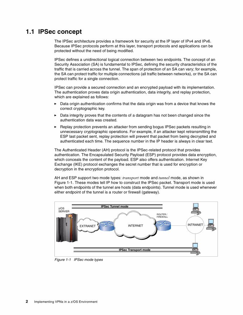
AH and ESP support two mode types: transport mode and tunnel mode, as shown in Figure 1-1. These modes tell IP how to construct the IPSec packet. Transport mode is used when both endpoints of the tunnel are hosts (data endpoints). Tunnel mode is used whenever either endpoint of the tunnel is a router or firewall (gateway).
Figure 1-1 IPSec mode types
INTERNET
IPSec Transport mode
INTRANET
ROUTER /FIREWALL
EXTRANET
z/OSSERVER
IPSec Tunnel mode
2 Implementing VPNs in a z/OS Environment
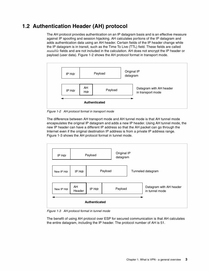
1.2 Authentication Header (AH) protocolThe AH protocol provides authentication on an IP datagram basis and is an effective measure against IP spoofing and session hijacking. AH calculates portions of the IP datagram and adds authentication data using an AH header. Certain fields of the IP header change while the IP datagram is in transit, such as the Time To Live (TTL) field. These fields are called mutable fields and are not included in the calculation. AH does not encrypt the IP header or payload (user data). Figure 1-2 shows the AH protocol format in transport mode.
Figure 1-2 AH protocol format in transport mode
The difference between AH transport mode and AH tunnel mode is that AH tunnel mode encapsulates the original IP datagram and adds a new IP header. Using AH tunnel mode, the new IP header can have a different IP address so that the AH packet can go through the Internet even if the original destination IP address is from a private IP address range. Figure 1-3 shows the AH protocol format in tunnel mode.
Figure 1-3 AH protocol format in tunnel mode
The benefit of using AH protocol over ESP for secured communication is that AH calculates the entire datagram, including the IP header. The protocol number of AH is 51.
IP Hdr PayloadOriginal IPdatagram
IP Hdr PayloadAHHdr
Datagram with AH headerin transport mode
Authenticated
IP Hdr PayloadOriginal IPdatagram
IPHdr Pay lo a d
Datagram with AH headerin tunnel mode
Authenticated
IP Hdr PayloadNew IP Hdr
IP Hdr PayloadNew IP HdrAHHeader
Tunneled datagram
Chapter 1. What is VPN - a general overview 3
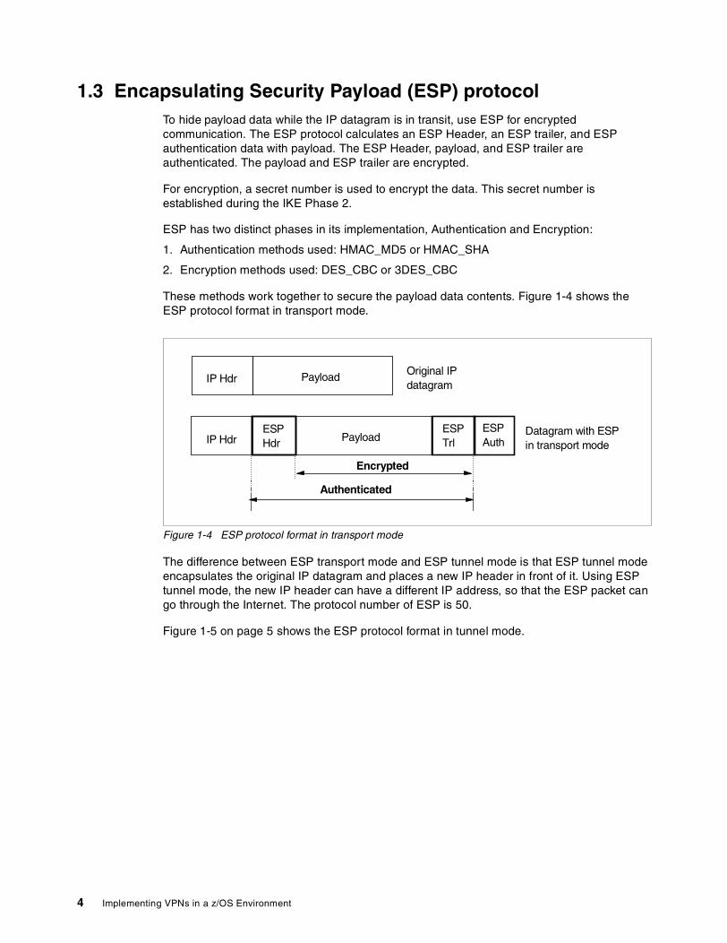
1.3 Encapsulating Security Payload (ESP) protocolTo hide payload data while the IP datagram is in transit, use ESP for encrypted communication. The ESP protocol calculates an ESP Header, an ESP trailer, and ESP authentication data with payload. The ESP Header, payload, and ESP trailer are authenticated. The payload and ESP trailer are encrypted.
For encryption, a secret number is used to encrypt the data. This secret number is established during the IKE Phase 2.
ESP has two distinct phases in its implementation, Authentication and Encryption:
1. Authentication methods used: HMAC_MD5 or HMAC_SHA
2. Encryption methods used: DES_CBC or 3DES_CBC
These methods work together to secure the payload data contents. Figure 1-4 shows the ESP protocol format in transport mode.
Figure 1-4 ESP protocol format in transport mode
The difference between ESP transport mode and ESP tunnel mode is that ESP tunnel mode encapsulates the original IP datagram and places a new IP header in front of it. Using ESP tunnel mode, the new IP header can have a different IP address, so that the ESP packet can go through the Internet. The protocol number of ESP is 50.
Figure 1-5 on page 5 shows the ESP protocol format in tunnel mode.
Authenticated
IP Hdr PayloadESPHdr
ESPTrl
ESPAuth
IP Hdr Payload Original IPdatagram
Datagram with ESPin transport mode
Encrypted
4 Implementing VPNs in a z/OS Environment

Figure 1-5 ESP protocol format in tunnel mode
1.4 SA combinationsThe AH and ESP protocols can be applied individually or in combination. The AH and ESP SAs do not need to use the same endpoints. In the network configuration shown in Figure 1-6, SA combinations are depicted. The SA for G1 and G2 is configured as an AH tunnel mode. The SA for H1 and H2 is configured as ESP transport mode. The SA combination with AH and ESP has the following benefits:
� AH improves network security
AH protocol authenticates portions of the IP datagram. If an intruder tries to send numerous invalid IP datagrams to slow down the server, AH protocol detects the invalid IP datagrams and discards them. AH protocol only forwards the valid IP datagram to the ESP layer, thus reducing the likelihood of the server being bogged down.
� ESP encrypts payload data
ESP protocol encrypts the payload data at the sender side H1, and the encrypted data goes through in the AH tunnel. The payload is decrypted at the receiver side H2. The payload is protected across the entire path.
IP Hdr PayloadOriginal IPdatagram
IPHdr Pa y lo ad
IP Hdr PayloadNew IP Hdr Tunneled datagram
IP Hdr PayloadESPHdr
Datagram with ESPin tunnel mode
Authenticated
Encrypted
New IP HdrESPTrl
ESPAuth
Chapter 1. What is VPN - a general overview 5
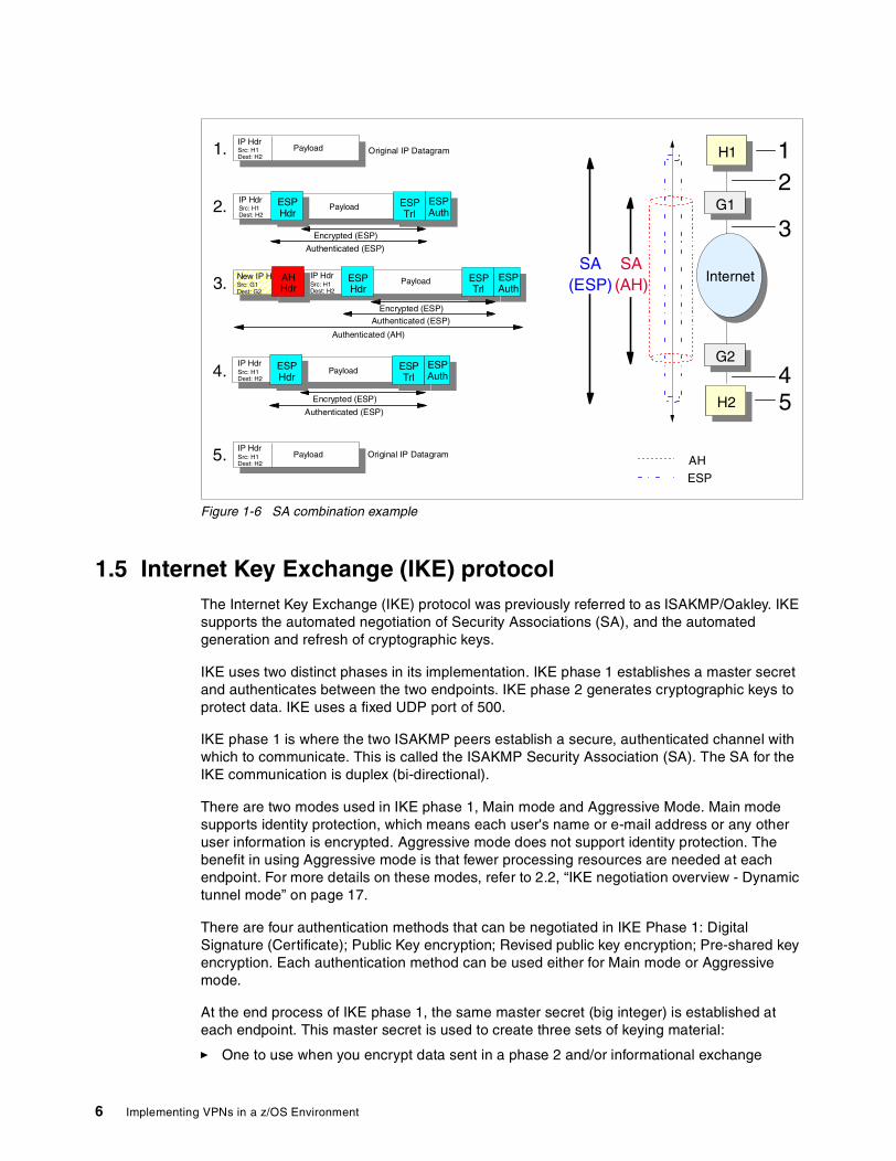
Figure 1-6 SA combination example
1.5 Internet Key Exchange (IKE) protocolThe Internet Key Exchange (IKE) protocol was previously referred to as ISAKMP/Oakley. IKE supports the automated negotiation of Security Associations (SA), and the automated generation and refresh of cryptographic keys.
IKE uses two distinct phases in its implementation. IKE phase 1 establishes a master secret and authenticates between the two endpoints. IKE phase 2 generates cryptographic keys to protect data. IKE uses a fixed UDP port of 500.
IKE phase 1 is where the two ISAKMP peers establish a secure, authenticated channel with which to communicate. This is called the ISAKMP Security Association (SA). The SA for the IKE communication is duplex (bi-directional).
There are two modes used in IKE phase 1, Main mode and Aggressive Mode. Main mode supports identity protection, which means each user's name or e-mail address or any other user information is encrypted. Aggressive mode does not support identity protection. The benefit in using Aggressive mode is that fewer processing resources are needed at each endpoint. For more details on these modes, refer to 2.2, “IKE negotiation overview - Dynamic tunnel mode” on page 17.
There are four authentication methods that can be negotiated in IKE Phase 1: Digital Signature (Certificate); Public Key encryption; Revised public key encryption; Pre-shared key encryption. Each authentication method can be used either for Main mode or Aggressive mode.
At the end process of IKE phase 1, the same master secret (big integer) is established at each endpoint. This master secret is used to create three sets of keying material:
� One to use when you encrypt data sent in a phase 2 and/or informational exchange
PayloadIP HdrSrc: H1Dest: H2
1.
2.
3.
4.
PayloadIP HdrSrc: H1Dest: H2
5.
ESPHdr
Payload ESPTrl
ESPAuth
IP HdrSrc: H1Dest: H2
Authenticated (ESP)
Encrypted (ESP)
ESPHdr
Payload ESPTrl
ESPAuth
IP HdrSrc: H1Dest: H2
New IP H.Src: G1Dest: G2
AHHdr
Authenticated (ESP)Encrypted (ESP)
Authenticated (AH)
ESPHdr
Payload ESPTrl
ESPAuth
IP HdrSrc: H1Dest: H2
Authenticated (ESP)
Encrypted (ESP)
H1
H2
G1
G2
Internet
12
3
4
AH
ESP
5
Original IP Datagram
Original IP Datagram
SA(AH)
SA(ESP)
6 Implementing VPNs in a z/OS Environment
� One to use when you authenticate messages sent in a phase 2 informational exchange
� One used for generating keys negotiated as the result of a phase 2 exchange (for example, keys used by the AH and ESP protocols).
Refer to 2.3.1, “Pre-shared key and RSA-based Signature” on page 23 for more information.
IKE phase 2 is where Security Associations are negotiated on behalf of services such as IPSec or any other service which needs key material and/or parameter negotiation. Quick mode accomplishes the phase 2 exchange.
Security Association (SA) Proposal is a concept where an encryption algorithm or authentication method would be used for the secured communication. In the IKE phase 1 negotiation, multiple SA proposals can be sent from the initiator side to the responder side. The responder side can choose only one of the SA proposals to establish the IKE communication.
In the IKE phase 2 negotiation, multiple SA proposals can be sent, and the responder side can choose multiple SA proposals to establish the multiple encrypted communication links. The SA for the secured communication links used for the AH or ESP protocols are simplex, which means each endpoint needs to choose two SA proposals to establish two encrypted communication links between the two endpoints.
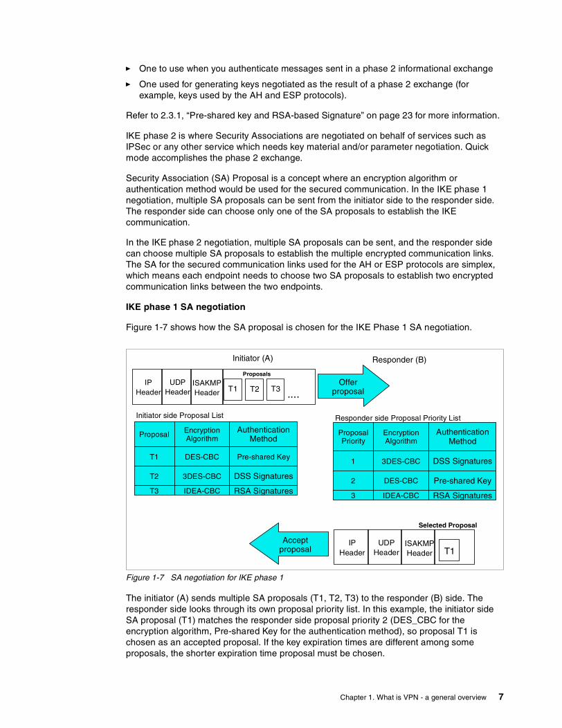
IKE phase 1 SA negotiation
Figure 1-7 shows how the SA proposal is chosen for the IKE Phase 1 SA negotiation.
Figure 1-7 SA negotiation for IKE phase 1
The initiator (A) sends multiple SA proposals (T1, T2, T3) to the responder (B) side. The responder side looks through its own proposal priority list. In this example, the initiator side SA proposal (T1) matches the responder side proposal priority 2 (DES_CBC for the encryption algorithm, Pre-shared Key for the authentication method), so proposal T1 is chosen as an accepted proposal. If the key expiration times are different among some proposals, the shorter expiration time proposal must be chosen.
IPHeader
UDPHeader
ISAKMPHeader ....
Proposals
T1 T2 T3
Proposal EncryptionAlgorithm
AuthenticationMethod
T1 DES-CBC Pre-shared Key
T2 3DES-CBC DSS Signatures
T3 IDEA-CBC RSA Signatures
Offerproposal
Initiator (A) Responder (B)
Acceptproposal
ProposalPriority
EncryptionAlgorithm
AuthenticationMethod
1 3DES-CBC DSS Signatures
2 DES-CBC Pre-shared Key
3 IDEA-CBC RSA Signatures
Responder side Proposal Priority ListInitiator side Proposal List
IPHeader
UDPHeader
ISAKMPHeader
Selected Proposal
T1
Chapter 1. What is VPN - a general overview 7
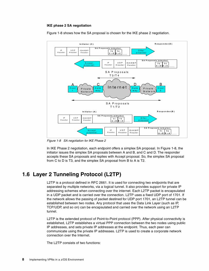
IKE phase 2 SA negotiation
Figure 1-8 shows how the SA proposal is chosen for the IKE phase 2 negotiation.
Figure 1-8 SA negotiation for IKE Phase 2
In IKE Phase 2 negotiation, each endpoint offers a simplex SA proposal. In Figure 1-8, the initiator issues the simplex SA proposals between A and B, and C and D. The responder accepts these SA proposals and replies with Accept proposal. So, the simplex SA proposal from C to D is T3, and the simplex SA proposal from B to A is T2.
1.6 Layer 2 Tunneling Protocol (L2TP)L2TP is a protocol defined in RFC 2661. It is used for connecting two endpoints that are separated by multiple networks, via a logical tunnel. It also provides support for private IP addressing schemes when connecting over the internet. Each L2TP packet is encapsulated in a UDP packet and is carried over the connection. L2TP uses a fixed UDP port of 1701. If the network allows the passing of packet destined for UDP port 1701, an L2TP tunnel can be established between two nodes. Any protocol that uses the Data Link Layer (such as IP, TCP/UDP, and so on) can be encapsulated and carried over the network using an L2TP tunnel.
L2TP is the extended protocol of Point-to-Point protocol (PPP). After physical connectivity is established, L2TP establishes a virtual PPP connection between the two nodes using public IP addresses, and sets private IP addresses at the endpoint. Thus, each peer can communicate using the private IP addresses. L2TP is used to create a corporate network connection over the Internet.
The L2TP consists of two functions:
O f f e rp r o p o s a l
In i t ia t o r ( C ) R e s p o n d e r ( D )
A c c e p tp r o p o s a l
IPH e a d e r
U D PH e a d e r
I S A K M PH e a d e r . . . .
S A P r o p o s a ls (s im p le x )
T 3C - > D
T 4D -> C
IPH e a d e r
U D PH e a d e r
IS A K M PH e a d e r . . . .
S A P r o p o s a ls (s im p le x )
T 3C - > D
T 4D - > C
I n te r n e tP r iv a teN e tw o r k
P r iv a t eN e tw o r k
G a t ew a y
G a t ew a y
H o s t1
H o s t2
S A P ro p o s a lsT 3 /T 4
A BC D
S A P r o p o s a lsT 1 /T 2
O f fe rp r o p o s a l
In i t i a t o r ( A ) R e s p o n d e r ( B )
A c c e p tp r o p o s a l
IPH e a d e r
U D PH e a d e r
IS A K M PH e a d e r . . . .
S A P r o p o s a ls (s im p le x )
T 1A - > B
T 2B - > A
IPH e a d e r
U D PH e a d e r
IS A K M PH e a d e r . . . .
S A P r o p o s a ls (s im p le x )
T 1A - > B
T 2B - > A
8 Implementing VPNs in a z/OS Environment

� L2TP Access Concentrator (LAC) is a node which acts as one side of an L2TP tunnel and is a peer to the L2TP Network Server (LNS). The LAC forwards packets to and from a remote system, and sits between an LNS and a remote system. Packets sent from the LAC to the LNS require tunneling with L2TP, while the connection from the LAC to the remote system can be either local (Client LAC) or via a network connection.
� L2TP Network Server (LNS) is a node which acts as one side of an L2TP tunnel endpoint and is a peer to the L2TP Access Concentrator (LAC). The LNS is the logical termination point of a virtual PPP session that is being tunneled from the remote system by the LAC.
Figure 1-9 shows the roles of L2TP Access Concentrator (LAC) and L2TP Network Server (LNS).
Figure 1-9 L2TP - LAC and LNS
Two L2TP tunnel modes: voluntary and compulsoryL2TP supports two tunnel modes: voluntary tunnel mode, and compulsory tunnel mode:
� In voluntary tunnel mode, the PPP client or the host must support the L2TP protocol. The L2TP supported client or host acts as an LAC, and it establishes the L2TP tunnel with a gateway that has an LNS role.
� In compulsory tunnel mode, the PPP client does not need to support L2TP protocol. The L2TP tunnel is established between an ISP that supports the LAC role, and a gateway that supports the LNS role. UDP port 1701 is used to establish the L2TP connection between LAC and LNS. Each L2TP packet is encapsulated in a UDP packet, and each UDP packet is carried over the connection.
An L2TP voluntary tunnel requires an L2TP-enabled client or host. An L2TP-enabled client or host acts as an LAC to establish a L2TP Voluntary Tunnel with an LNS. A global routeable IP address needs to be assigned on both Client (LAC) and Gateway (LNS) to let UDP packets go through the Internet. Figure 1-10 on page 10 shows the L2TP voluntary tunnel.
ISP CorporateGatewayInternet
L2TP AccessConcentrator(LAC)
CorporateNetwork
L2TP NetworkServer (LNS)
Physical PPPConnection
Virtual PPP Connection (L2TP Tunnel)
Chapter 1. What is VPN - a general overview 9

Figure 1-10 L2TP voluntary tunnel - PPP connection case
A PPP connection is not mandatory for the voluntary tunnel mode. Any connection configuration, such as a direct LAN connection or a broadband connection with a ISP, can be used for the L2TP supported client or host. In the L2TP tunnel, PPP packets are encapsulated within UDP packets and are carried over the network. Figure 1-11 shows the L2TP voluntary tunnel with broadband connection case.
Figure 1-11 L2TP voluntary tunnel - broadband connection case
An L2TP compulsory tunnel does not require an L2TP-enabled client or host. Using an L2TP compulsory tunnel, a PPP connection is mandatory between the client and the ISP. The ISP must have a LAC function to establish an L2TP compulsory tunnel with LNS. A global routeable IP address needs to be assigned on both ISP (LAC) and Gateway (LNS) to let UDP packets go through the Internet. Figure 1-12 on page 11 shows the L2TP compulsory tunnel.
ISP CorporateGatewayInternet
L2TP AccessConcentrator(LAC) Corporate
Network
PPPDialupConnection
L2TP Voluntary Tunnel
UDPport 1701
UDPport 1701
L2TP PacketsUDP
L2TP NetworkServer (LNS)
CorporateGatewayInternet
L2TP AccessConcentrator(LAC) Corporate
Network
BroadbandConnection
L2TP Voluntary Tunnel
Router
L2TP PacketsUDP
L2TP NetworkServer (LNS)
UDPport 1701
UDPport 1701
10 Implementing VPNs in a z/OS Environment
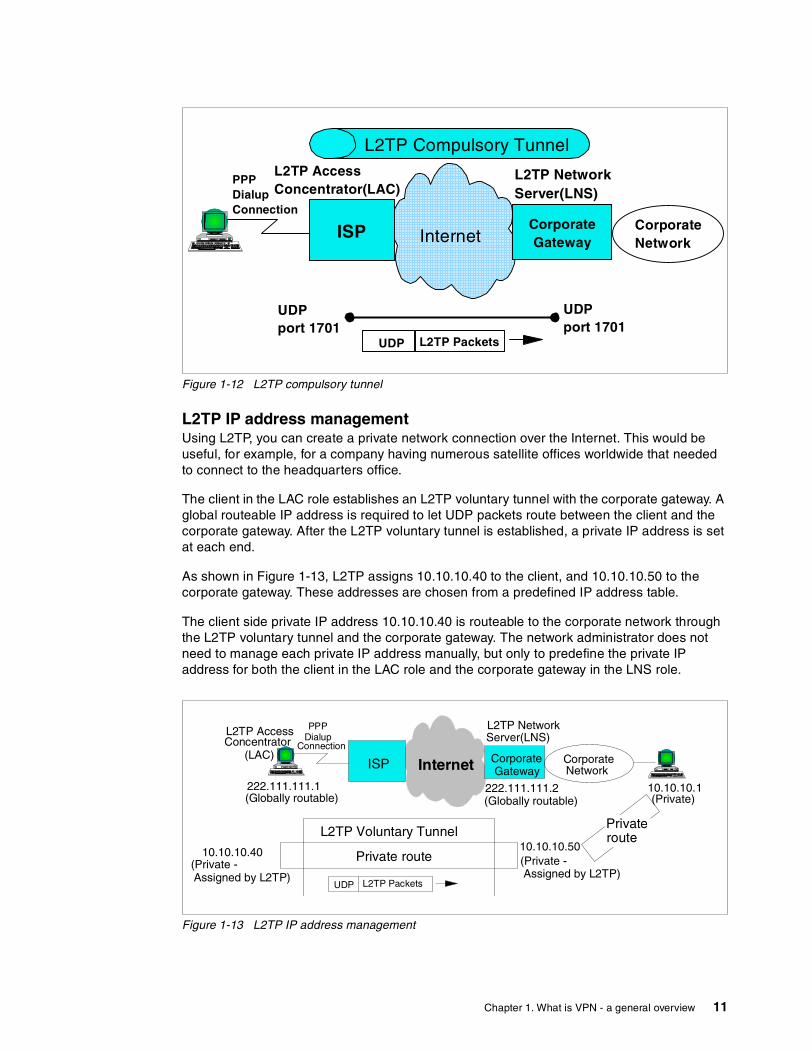
Figure 1-12 L2TP compulsory tunnel
L2TP IP address managementUsing L2TP, you can create a private network connection over the Internet. This would be useful, for example, for a company having numerous satellite offices worldwide that needed to connect to the headquarters office.
The client in the LAC role establishes an L2TP voluntary tunnel with the corporate gateway. A global routeable IP address is required to let UDP packets route between the client and the corporate gateway. After the L2TP voluntary tunnel is established, a private IP address is set at each end.
As shown in Figure 1-13, L2TP assigns 10.10.10.40 to the client, and 10.10.10.50 to the corporate gateway. These addresses are chosen from a predefined IP address table.
The client side private IP address 10.10.10.40 is routeable to the corporate network through the L2TP voluntary tunnel and the corporate gateway. The network administrator does not need to manage each private IP address manually, but only to predefine the private IP address for both the client in the LAC role and the corporate gateway in the LNS role.
Figure 1-13 L2TP IP address management
ISP CorporateGatewayInternet
L2TP AccessConcentrator(LAC)
CorporateNetwork
PPPDialupConnection
L2TP NetworkServer(LNS)
L2TP Compulsory Tunnel
L2TP PacketsUDP
UDPport 1701
UDPport 1701
ISP CorporateGatewayInternet
L2TP AccessConcentrator
(LAC) CorporateNetwork
PPPDialup
Connection
L2TP NetworkServer(LNS)
222.111.111.1(Globally routable)
L2TP PacketsUDP
222.111.111.2(Globally routable)
10.10.10.1(Private)
10.10.10.50
Assigned by L2TP)
10.10.10.40(Private -Assigned by L2TP)
Private route
PrivaterouteL2TP Voluntary Tunnel
(Private -
Chapter 1. What is VPN - a general overview 11
1.7 Network Address Translation (NAT)NAT is a protocol defined in RFC 1631. It is used to convert a private IP address to a globally routeable (public) IP address at a firewall or at a router. NAT itself provides a simple IP address conversation table between a private IP address and a public IP address.
After the IP address conversion is done, IP checksum and TCP checksum are recalculated and updated.
There are three NAT variations:
1. Static NAT 2. Dynamic NAT 3. Network Address Port Translation (NAPT)
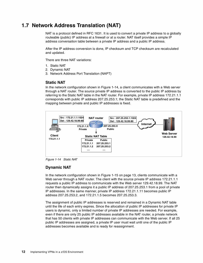
Static NATIn the network configuration shown in Figure 1-14, a client communicates with a Web server through a NAT router. The source private IP address is converted to the public IP address by referring to the Static NAT table in the NAT router. For example, private IP address 172.21.1.1 corresponds with public IP address 207.25.253.1; the Static NAT table is predefined and the mapping between private and public IP addresses is fixed.
Figure 1-14 Static NAT
Dynamic NAT
In the network configuration shown in Figure 1-15 on page 13, clients communicate with a Web server through a NAT router. The client with the source private IP address 172.21.1.1 requests a public IP address to communicate with the Web server 129.42.18.99. The NAT router then dynamically assigns it a public IP address of 207.25.253.1 from a pool of private IP addresses. In the same manner, private IP address 172.21.1.11 becomes public IP address 207.25.253.2, and 172.21.1.5 becomes 207.25.253.3.
The assignment of public IP addresses is reserved and remained in a Dynamic NAT table until the life of each entry expires. Since the allocation of public IP addresses for private IP users is dynamic, only a limited number of private IP addresses are needed. For example, even if there are only 25 public IP addresses available in the NAT router, a private network that has 50 clients with private IP addresses can communicate with the Web server. If all 25 public IP addresses are assigned, a private IP user must wait until one of the public IP addresses becomes available and is ready for reassignment.
NAT routerSrc : 172.21.1.1:1024Dst : 129.42.18.99:80
Client172.21.1.1
Internet
Src : 207.25.253.1:1024Dst : 129.42.18.99:80
172.21.1.XPrivate
207.25.253.XPublic
Web Server129.42.18.99Static NAT Table
Private Public172.21.1.1 207.25.253.1172.21.1.2 207.25.253.2
.... ....
12 Implementing VPNs in a z/OS Environment
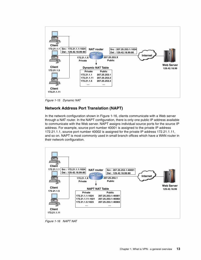
Figure 1-15 Dynamic NAT
Network Address Port Translation (NAPT)
In the network configuration shown in Figure 1-16, clients communicate with a Web server through a NAT router. In the NAPT configuration, there is only one public IP address available to communicate with the Web server. NAPT assigns individual source ports for the source IP address. For example, source port number 40001 is assigned to the private IP address 172.21.1.1, source port number 40002 is assigned for the private IP address 172.21.1.11, and so on. NAPT is most commonly used in small branch offices which have a WAN router in their network configuration.
Figure 1-16 NAPT NAT
NAT routerSrc : 172.21.1.1:1024Dst : 129.42.18.99:80
Client172.21.1.5
Internet
Src : 207.25.253.1:1024Dst : 129.42.18.99:80
172.21.1.XPrivate
207.25.253.XPublic
Web Server129.42.18.99Dynamic NAT Table
Private Public172.21.1.1 207.25.253.1172.21.1.11 207.25.253.2172.21.1.5 207.25.253.3
.... ....
Client172.21.1.11
Client172.21.1.1
NAT routerSrc : 172.21.1.1:1024Dst : 129.42.18.99:80
Client172.21.1.5
Internet
Src : 207.25.253.1:40001Dst : 129.42.18.99:80
172.21.1.XPrivate
207.25.253.1Public
Web Server129.42.18.99NAPT NAT Table
Private Public172.21.1.1:1024 207.25.253.1:40001172.21.1.11:1021 207.25.253.1:40002172.21.1.5:1023 207.25.253.1:40003
.... ....
Client172.21.1.11
Client172.21.1.1
Chapter 1. What is VPN - a general overview 13

14 Implementing VPNs in a z/OS Environment

Chapter 2. What is implemented in z/OS VPN
This chapter provides detailed information for z/OS VPN installations. There are many parameters to choose from when making a VPN configuration. It is important to understand the meaning of each parameter to make the right choice to satisfy your VPN requirements.
We explain the details of the following in this chapter:
� Manual tunnels and Dynamic tunnels
We provide an overview of Manual and Dynamic tunnels, including the differences between them.
� IKE Negotiation sequence overview – Dynamic tunnel mode
We supply the details of Internet Key Exchange (IKE) protocol Phase1 and IKE Phase 2 negotiation sequence.
� Know the difference – to make the best choice
We explain the difference of each parameter to help you make the best choice for your VPN configuration.
� What is implemented in a z/OS Firewall Technologies
We provide implementation information for z/OS VPN support.
2
© Copyright IBM Corp. 2002 15
2.1 Manual tunnels and Dynamic tunnelsz/OS VPN supports two different tunnel mode types: Manual and Dynamic.
Manual tunnels are most commonly used for VPN tunnels between two endpoints that do not require any type of key exchange. A Manual tunnel does not support Internet Key Exchange (IKE), it has a predefined configuration for authentication and encryption and its connectivity is limited to Manual tunnel supported servers or routers.
Dynamic tunnels support IKE (also known as ISAKMP). With the use of Dynamic tunnel mode, z/OS servers can be connected with servers or routers which support IPSec standard (RFC 2401 - 2410).
2.1.1 Manual tunnelsA Manual tunnel provides backward compatibility to all header types and will interoperate with non-IBM machines or those that do not have ISAKMP support. The disadvantage of using manual tunnels is that the configuration values are predefined and static. In other words, the encryption and authentication configuration values are the same for the life of the tunnel and must be manually modified when new values are required.
Manual tunnels can be used between two hosts which have z/OS Firewall software running, or between a host which has z/OS Firewall software running and any other machine that has the same set of authentication and encryption algorithms. Most vendors provide support for Keyed_MD5 with DES or HMAC_MD5 with DES. These are a base subset that work with most implementations of IP Security (IPSec).
The ability to interoperate with another z/OS system is simplified by using the export/import capability of the fwtunnl command or Virtual Private Network selection on the configuration client GUI. This capability allows a tunnel definition to be exported from one system and imported into another.
The fwtunnl command and configuration client provide the ability to define and display the complete list of parameters which comprise a tunnel definition. This capability should be used when interoperating with a system that does not support the z/OS export file formats. Manual configuration can be performed in one of two ways:
� Define and list the tunnel on z/OS. Then you must analyze the tunnel definitions, understand the format of the displayed data, and manually input this data into the non-IBM system using whatever mechanism is provided.
� Define the tunnel on the non-z/OS system and determine the values of all parameters which define the tunnel. Then the fwtunnl command or configuration client must be used to input all of the same tunnel definition parameters on the z/OS system.
Only after performing one of these two steps will the same security association exist on both systems. Use the fwtunnl command or Virtual Private Network selection on the configuration client GUI to add, delete, change, import, export, activate, deactivate, and shut down a manual tunnel. The fwtunnl command also displays the currently active manual tunnels.
For more information on configuring Manual tunnels, refer to SecureWay Security Server FireWall Technologies, SC24-5922.
16 Implementing VPNs in a z/OS Environment

2.1.2 Dynamic tunnels (ISAKMP)A Dynamic tunnel is based on the ISAKMP standards provided by IETF. Dynamic tunnels use IKE to exchange authentication methods without exposing the key material on the network. Two types of cryptographic key materials can be used for z/OS Dynamic tunnel authentication; Pre-Shared Key and Digital Signature.
IKE negotiation uses a two-phase approach. IKE Phase 1 authenticates each peer with the communicating parties and specifies the method for securing Phase 2 exchanges and information exchanges. In IKE Phase 2, IP security associations (SAs) are negotiated and keys are exchanged. The following ISAKMP support is available:
� Authentication with Pre-Shared Keys
� Use of main mode (identity protect mode) and aggressive mode
� Support for Diffie-Hellman groups 1 and 2
� ESP support for 3DES, DES, Null, and authentication with HMAC_MD5 and HMAC_SHA
� AH support for HMAC_MD5 and HMAC_SHA
The ISAKMP support is based on the following IETF standards:
� RFC 2407 - The Internet IP Domain of Interpretation for ISAKMP
� RFC 2408 - The Internet Security Association and Key Management Protocol (ISAKMP)
� RFC 2409 - The Internet Key Exchange
2.1.3 Manual and Dynamic tunnels: Summary of differencesTable 2-1 summarizes the differences between Dynamic tunnel mode and Manual tunnel mode.
Table 2-1 Differences between Dynamic tunnel mode and Manual tunnel mode
2.2 IKE negotiation overview - Dynamic tunnel modeAs we described previously, Dynamic tunnel mode uses IKE Phase 1 and IKE Phase 2 negotiation. The sequence of IKE Phase 1 negotiation is as follows:
1. Negotiate SA proposal for IKE Phase 1 negotiation from SA proposals, which is sent from Initiator.
2. Exchange Diffie-Hellman public value and generate the same integer. This integer value, known as g*xy, is then input into a series of pseudo-random function (prf) invocations (such as HMAC_MD5 or HMAC_SHA) to produce 3 sets of groups of keying material:
Dynamic tunnel mode Manual tunnel mode
SA attributes are agreed to through IKE negotiation.
SA attributes are agreed through out-of-band communication and must be predefined locally.
Cryptographic keys are established through IKE negotiation.
Cryptographic keys are established through out-of-band communication and must be predefined locally.
Provides authentication through pre-shared keys or RSA signatures.
Provides authentication through shared secret keys.
Cryptographic keys are automatically refreshed in a non-disruptive manner.
Cryptographic keys must be refreshed out-of-band and require the deactivation of the VPN to take effect.
Chapter 2. What is implemented in z/OS VPN 17
SKEYID_d, SKEYID_a, and SKEYID_e. These groups of keying material will be used during IKE phase 2 to derive keys used to protect data sent through a dynamic tunnel, to authenticate the origin of a Phase 2 message, and to encrypt the contents of a Phase 2 message.
3. Exchange identity information. This information will be used to identify what security policy should be applied to this dynamic tunnel.
4. Exchange authentication information. This information includes the output of a pseudo-random function (for example, HMAC_MD5 or HMAC_SHA). Input into the pseudo-random function includes both the identity exchanged and the g*xy value calculated by the Diffie-Hellman exchange.
The sequence of IKE Phase 2 negotiation is as follows:
1. Negotiate SA proposals for AH and/or ESP communications.
2. Exchange Diffie-Hellman public values and calculate an addition g*xy value (optional).
3. Exchange identify information (optional).
4. Use a pseudo-random function (such as HMAC_MD5 or HMAC_SHA) to calculate cryptographic keying material. Input into this pseudo-random function will include the SKEYID_d value derived during phase 1. This keying material will be used to generate the keys required by the SA proposal(s) selected previously (for AH and/or ESP).
There are two modes in IKE Phase 1; Main mode and Aggressive mode. Main mode has six messages to exchange between the Initiator and the Responder, Aggressive mode has three messages to exchange. Main mode supports identity protection, Aggressive mode does not. Since Aggressive mode has fewer messages to exchange, Aggressive mode requires less processing overhead than Main mode.
In the following sections we explain the negotiation sequence for IKE Phase 1 Main mode with RSA Signature Authentication and IKE Phase 1 Aggressive mode with RSA Signature Authentication.
2.2.1 IKE Phase 1 Main mode with Signature AuthenticationFigure 2-1 on page 19 shows messages 1 and 2 of IKE Phase 1 Main mode with Signature Authentication.
Note: Portions of each message exchanged during IKE phase 2 will be encrypted. The key used to encrypt these messages is derived from SKEYID_e. Each message exchanged during IKE phase 2 contains a hash generated by using a pseudo-random function. Input to this pseudo-random function includes SKEYID_a and other data sent in the message. An IKE phase 2 message can be authenticated by recalculating this hash and comparing the value sent in the message.
18 Implementing VPNs in a z/OS Environment
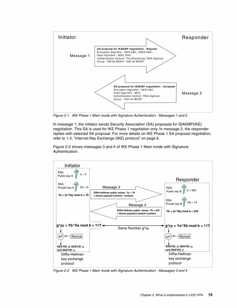
Figure 2-1 IKE Phase 1 Main mode with Signature Authentication - Messages 1 and 2
In message 1, the initiator sends Security Association (SA) proposals for ISAKMP(IKE) negotiation. This SA is used for IKE Phase 1 negotiation only. In message 2, the responder replies with selected SA proposal. For more details on IKE Phase 1 SA proposal negotiation, refer to 1.5, “Internet Key Exchange (IKE) protocol” on page 6.
Figure 2-2 shows messages 3 and 4 of IKE Phase 1 Main mode with Signature Authentication.
Figure 2-2 IKE Phase 1 Main mode with Signature Authentication - Messages 3 and 4
SA proposal for ISAKMP negotiation - RequestEncryption Algorithm : DES-CBC, 3DES-CBC..Hash Algorithm : MD5, SHAAuthentication method : Pre-Shared key, RSA SigntureGroup : 768 bit MODP, 1024 bit MODP
SA proposal for ISAKMP negotiation - AcceptedEncryption Algorithm : DES-CBCHash Algorithm : MD5Authentication method : RSA SigntureGroup : 1024 bit MODP
Initiator Responder
Message 1
Message 2
Diffie-Hellman public values Ya = 78+ Nonce payload (random number)
Initiator
Responder
Message 3
Message 4
RSAPublic key A
RSAPrivate key A
a = 5
Xa = 9
Ya = (a^Xa) mod b = 78
Diffie-Hellman public values Yb = 534+ Nonce payload (random number)
RSAPublic key B
RSAPrivate key B
b = 563
Xb = 14
Yb = (a^Xb) mod b = 534
g*xy = Yb^Xa mod b = 117 g*xy = Ya^Xb mod b = 117Same Number g*xy
Nonce Nonce
SKEYID_d, SKEYID_a,and SKEYID_e
Diffie-Hellmankey exchangeprotocol
Diffie-Hellmankey exchangeprotocol
prf prf
SKEYID_d, SKEYID_a,and SKEYID_e
Chapter 2. What is implemented in z/OS VPN 19

In message 3 and 4, the initiator and the responder exchange the Diffie-Hellman public value. The Diffie-Hellman algorithm creates the secret number g*xy, which is used to create the SKEYID_d, SKEYID_a, and SKEYID_e. Using the Diffie-Hellman algorithm, the initiator and the responder can exchange the private keys without exposing them to the public.
At first, the Initiator has a, Xa, and b on hand and the responder has b, Xb, and a on hand. The initiator and the responder calculate the Diffie-Hellman public value Ya, Yb to exchange. If an intruder is listening to the conversation between the initiator and the responder, an intruder will have a, b, Ya, and Yb. However, an intruder cannot calculate the private key value nor secret number g*xy from a, b, Ya, and Yb. This is the benefit of using the Diffie-Hellman algorithm to exchange the private keys between the initiator and the responder.
The nonce payload contains a randomly generated number. This number, the g*xy value, and other data is input into a series of pseudo-random function (prf) invocations to create the SKEYID_d, SKEYID_e, and SKEYID_a.
Figure 2-3 on page 20 shows messages 5 and 6 of IKE Phase 1 Main mode with RSA Signature Authentication.
Figure 2-3 IKE Phase 1 Main mode with Signature Authentication - Messages 5 and 6
In message 5 and 6, Identification payload is exchanged between the initiator and the responder. This Identification payload itself does not work for the identification. The Identification payload includes the information of the initiator or the responder. The identity in the Identification payload and other data exchanged between the two parties are input into a pseudo-random function (prf). The output of this function is then encrypted with the appropriate private key to create an RSA signature. Both parties exchange signatures in messages 5 and 6. To verify a signature, the RSA signature received is decrypted with the appropriate public key. The result of this decryption is the output of the prf calculated by the creator of the signature. To validate that this prf value is correct, the prf is recalculated by the receiver of the signature.
Initiator ResponderMessage 5
Message 6
Identification PayloadRSA SignatureSignature (Source of RSA Signature)
Identification PayloadRSA SignatureSignature (Source of RSA Signature)
RSASignature"received"
Identity-email address-name
Hashalgorithm
RSAdecryption
HashData
HashData
Verify
RSASignature"received"
Identity-email address-name
Hashalgorithm
RSAdecryption
HashData
HashData
Verify
VerifyOK
VerifyOK
Identity Authentication complete
RSA Signature verification RSA Signature verification
Verify
20 Implementing VPNs in a z/OS Environment
Recall, the sender’s identity is input to the prf, thus by verifying the signature, the sender’s identity is also authenticated. In RSA signature mode, a further verification check of the identity sent is performed. The identity checked must match either the subject name or the subject alternate name contained in the certificate used to obtain the public key used when decrypting the signature. The initiator and the responder calculate the hash data from the Signature text and RSA Signature, then compare each hash data. If the hash data is the same, the identities of the initiator and the responder are authenticated.
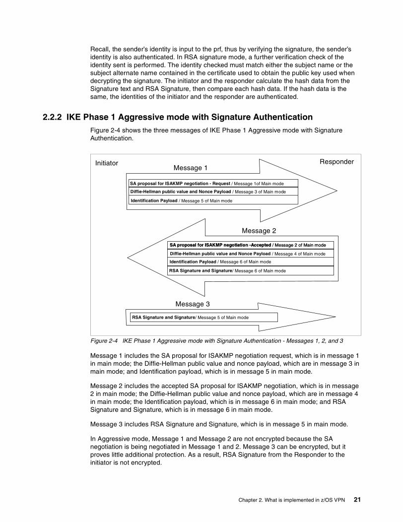
2.2.2 IKE Phase 1 Aggressive mode with Signature AuthenticationFigure 2-4 shows the three messages of IKE Phase 1 Aggressive mode with Signature Authentication.
Figure 2-4 IKE Phase 1 Aggressive mode with Signature Authentication - Messages 1, 2, and 3
Message 1 includes the SA proposal for ISAKMP negotiation request, which is in message 1 in main mode; the Diffie-Hellman public value and nonce payload, which are in message 3 in main mode; and Identification payload, which is in message 5 in main mode.
Message 2 includes the accepted SA proposal for ISAKMP negotiation, which is in message 2 in main mode; the Diffie-Hellman public value and nonce payload, which are in message 4 in main mode; the Identification payload, which is in message 6 in main mode; and RSA Signature and Signature, which is in message 6 in main mode.
Message 3 includes RSA Signature and Signature, which is in message 5 in main mode.
In Aggressive mode, Message 1 and Message 2 are not encrypted because the SA negotiation is being negotiated in Message 1 and 2. Message 3 can be encrypted, but it proves little additional protection. As a result, RSA Signature from the Responder to the initiator is not encrypted.
SA proposal for ISAKMP negotiation -Accepted / Message 2 of Main mode
Diffie-Hellman public value and Nonce Payload / Message 4 of Main mode
Identification Payload / Message 6 of Main mode
RSA Signature and Signature/ Message 6 of Main mode
SA proposal for ISAKMP negotiation - Request / Message 1of Main mode
Diffie-Hellman public value and Nonce Payload / Message 3 of Main mode
Identification Payload / Message 5 of Main mode
Message 1
Message 2
RSA Signature and Signature/ Message 5 of Main mode
Message 3
Initiator Responder
SA proposal for ISAKMP negotiation -Accepted / Message 2 of Main mode
Chapter 2. What is implemented in z/OS VPN 21
If you want the identities exchanged to be protected, you must use Main mode. In Main mode, messages 5 and 6 are encrypted using the SA negotiated in message 1 and 2 using keying material generated during the processing of messages 3 and 4.
If you do not have the required processing power in each router or each server, you should use Aggressive mode instead of Main mode. Aggressive mode is also recommended when one or both of the phase 1 peers are using a dynamically obtained IP address.
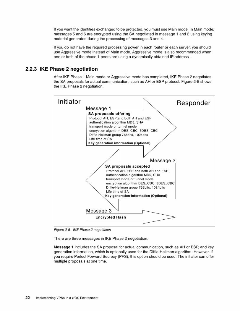
2.2.3 IKE Phase 2 negotiation After IKE Phase 1 Main mode or Aggressive mode has completed, IKE Phase 2 negotiates the SA proposals for actual communication, such as AH or ESP protocol. Figure 2-5 shows the IKE Phase 2 negotiation.
Figure 2-5 IKE Phase 2 negotiation
There are three messages in IKE Phase 2 negotiation:
Message 1 includes the SA proposal for actual communication, such as AH or ESP, and key generation information, which is optionally used for the Diffie-Hellman algorithm. However, if you require Perfect Forward Secrecy (PFS), this option should be used. The initiator can offer multiple proposals at one time.
Initiator Responder
SA proposals offeringProtocol AH, ESP,and both AH and ESPauthentication algorithm MD5, SHAtransport mode or tunnel modeencryption algorithm DES_CBC, 3DES_CBCDiffie-Hellman group 768bits, 1024bitsLife time of SA
Key generation information (Optional)
SA proposals acceptedProtocol AH, ESP,and both AH and ESPauthentication algorithm MD5, SHAtransport mode or tunnel modeencryption algorithm DES_CBC, 3DES_CBCDiffie-Hellman group 768bits, 1024bitsLife time of SA
Key generation information (Optional)
Encrypted Hash
Message 1
Message 2
Message 3
22 Implementing VPNs in a z/OS Environment

Message 2 includes the accepted SA proposals. Notice that these SA proposals are simplex. If you are going to establish an ESP tunnel between the initiator and the responder, it needs two SA proposals: from the initiator to the responder, and from the responder to the initiator. For details of IKE Phase 2 SA negotiation, refer to 1.5, “Internet Key Exchange (IKE) protocol” on page 6. Message 2 also includes key generation information, which is optionally used for the Diffie-Hellman algorithm.
Message 3 includes the encrypted hash. It is a reply from the initiator to the responder, which means all messages from the responder are successfully processed at the initiator side.
2.3 Know the difference – to make the best choiceTo create a VPN configuration, there are many parameters to choose from. It is important to understand the difference or meaning of each parameter. In this section, we explain the differences among these parameters.
2.3.1 Pre-shared key and RSA-based Signaturez/OS supports Pre-shared key and RSA-based Signature for IKE Phase 1 authentication.
Pre-shared key authenticationA Pre-shared key is a predefined alphanumeric value; such as 1234ABCD. The Initiator and the Responder share the same Pre-shared key before they start the conversation. Figure 2-6 shows the details of Pre-shared key authentication.
Figure 2-6 Pre-shared key authentication
First, SKEYID is calculated from a pre-shared key and two nonces; Ni_b and Nr_b. Notice that Ni_b( Nonce from Initiator) and Nr_b( Nonce from Responder) are exchanged in message 3 and message 4 in IKE main mode. Hash_I and Hash_R are calculated and exchanged in message 5 and message 6 in IKE main mode. After the value of Hash_I and Hash_R are validated, the authentication is completed.
1. Calculation of SKEYID SKEYID = prf (pre-shared key, Ni_b | Nr_b)
prf (A, B): Creates Hash with key A, message B, and Hash algorithm prf(e.g. HMAC_MD5)Ni_b | Nr_b: Concatenation of Initiator Nonce Ni_b and Responder Nonce Nr_bpre-shared key: pre-shared key
2. Calculation of Hash_I, Hash_R Initiator side: Hash_I = prf (SKEYID , g^xi | g^xr | CKY-I | CKY-R | SAi_b | IDii_b)Responder side: Hash_R = prf (SKEYID , g^xr | g^xi | CKY-R | CKY-I | SAi_b | IDir_b)
SKEYID: Calculated in the previous stepg^xi: Diffie-Hellman ([DH]) public values of the initiatorg^xr: Diffie-Hellman ([DH]) public values of the responderCKY-I: Initiator's cookie from the ISAKMP headerCKY-R: Responder's cookie from the ISAKMP headerSAi_b: The entire body of the SA payload (minus the ISAKMP generic header)IDii: The identification payload for the ISAKMP initiator during phase 1 negotiationIDir: The identification payload for the ISAKMP responder during phase 1 negotiation
3. Authentication Initiator side: Send Hash_I to responderResponder side: Send Hash_R to initiatorAuthentication is done on Initiator side and Responder side
Chapter 2. What is implemented in z/OS VPN 23
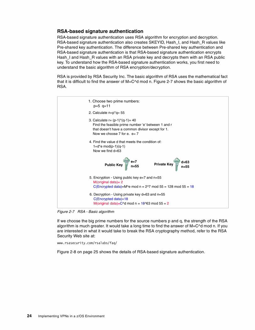
RSA-based signature authenticationRSA-based signature authentication uses RSA algorithm for encryption and decryption. RSA-based signature authentication also creates SKEYID, Hash_I, and Hash_R values like Pre-shared key authentication. The difference between Pre-shared key authentication and RSA-based signature authentication is that RSA-based signature authentication encrypts Hash_I and Hash_R values with an RSA private key and decrypts them with an RSA public key. To understand how the RSA-based signature authentication works, you first need to understand the basic algorithm of RSA encryption/decryption.
RSA is provided by RSA Security Inc. The basic algorithm of RSA uses the mathematical fact that it is difficult to find the answer of M=C^d mod n. Figure 2-7 shows the basic algorithm of RSA.
Figure 2-7 RSA - Basic algorithm
If we choose the big prime numbers for the source numbers p and q, the strength of the RSA algorithm is much greater. It would take a long time to find the answer of M=C^d mod n. If you are interested in what it would take to break the RSA cryptography method, refer to the RSA Security Web site at:
www.rsasecurity.com/rsalabs/faq/
Figure 2-8 on page 25 shows the details of RSA-based signature authentication.
1. Choose two prime numbers:p=5 q=11
2. Calculate n=p*q= 55
3. Calculate r= (p-1)*(q-1)= 40Find the feasible prime number 'e' between 1 and rthat doesn't have a common divisor except for 1.Now we choose 7 for e. e= 7
4. Find the value d that meets the condition of:1=d*e mod(p-1)(q-1)Now we find d=63
Public Keye=7n=55 Private Key
d=63n=55
5. Encryption - Using public key e=7 and n=55M(original data)= 2C(Encrypted data)=M^e mod n = 2^7 mod 55 = 128 mod 55 = 18
6. Decryption - Using private key d=63 and n=55C(Encrypted data)=18M(original data)=C^d mod n = 18^63 mod 55 = 2
24 Implementing VPNs in a z/OS Environment
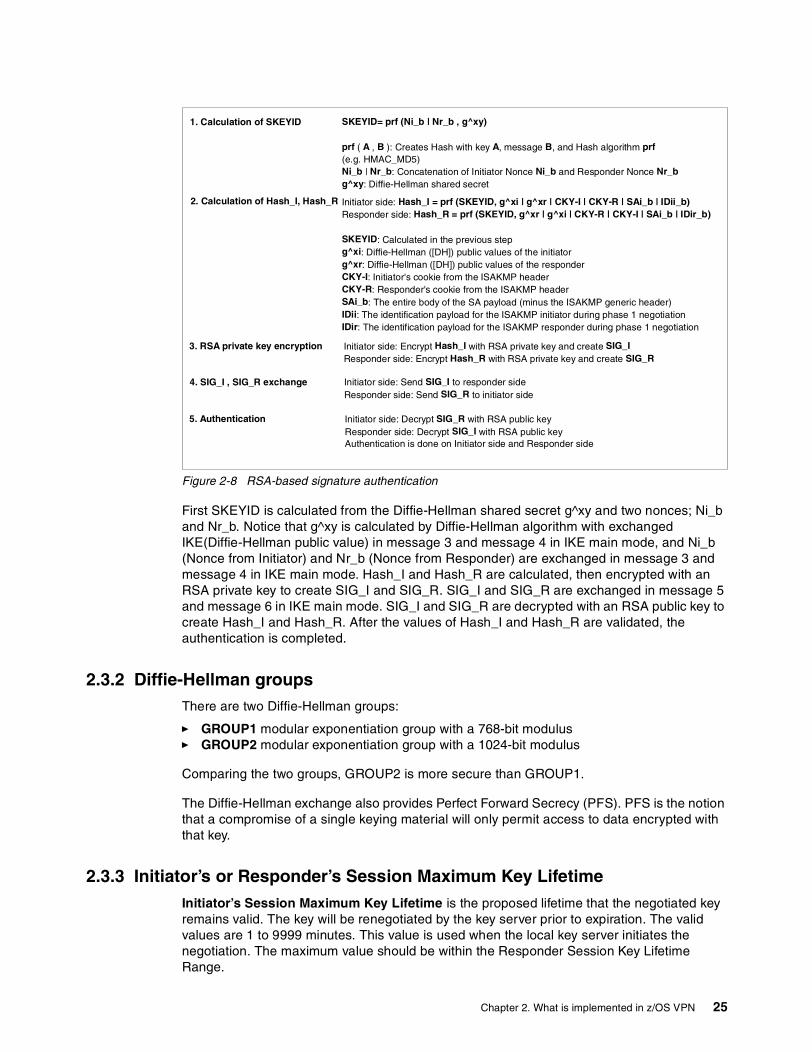
Figure 2-8 RSA-based signature authentication
First SKEYID is calculated from the Diffie-Hellman shared secret g^xy and two nonces; Ni_b and Nr_b. Notice that g^xy is calculated by Diffie-Hellman algorithm with exchanged IKE(Diffie-Hellman public value) in message 3 and message 4 in IKE main mode, and Ni_b (Nonce from Initiator) and Nr_b (Nonce from Responder) are exchanged in message 3 and message 4 in IKE main mode. Hash_I and Hash_R are calculated, then encrypted with an RSA private key to create SIG_I and SIG_R. SIG_I and SIG_R are exchanged in message 5 and message 6 in IKE main mode. SIG_I and SIG_R are decrypted with an RSA public key to create Hash_I and Hash_R. After the values of Hash_I and Hash_R are validated, the authentication is completed.
2.3.2 Diffie-Hellman groupsThere are two Diffie-Hellman groups:
� GROUP1 modular exponentiation group with a 768-bit modulus� GROUP2 modular exponentiation group with a 1024-bit modulus
Comparing the two groups, GROUP2 is more secure than GROUP1.
The Diffie-Hellman exchange also provides Perfect Forward Secrecy (PFS). PFS is the notion that a compromise of a single keying material will only permit access to data encrypted with that key.
2.3.3 Initiator’s or Responder’s Session Maximum Key Lifetime Initiator’s Session Maximum Key Lifetime is the proposed lifetime that the negotiated key remains valid. The key will be renegotiated by the key server prior to expiration. The valid values are 1 to 9999 minutes. This value is used when the local key server initiates the negotiation. The maximum value should be within the Responder Session Key Lifetime Range.
1. Calculation of SKEYID SKEYID= prf (Ni_b | Nr_b , g^xy)
prf ( A , B ): Creates Hash with key A, message B, and Hash algorithm prf(e.g. HMAC_MD5)Ni_b | Nr_b: Concatenation of Initiator Nonce Ni_b and Responder Nonce Nr_bg^xy: Diffie-Hellman shared secret
2. Calculation of Hash_I, Hash_R Initiator side: Hash_I = prf (SKEYID, g^xi | g^xr | CKY-I | CKY-R | SAi_b | IDii_b)Responder side: Hash_R = prf (SKEYID, g^xr | g^xi | CKY-R | CKY-I | SAi_b | IDir_b)
SKEYID: Calculated in the previous stepg^xi: Diffie-Hellman ([DH]) public values of the initiatorg^xr: Diffie-Hellman ([DH]) public values of the responderCKY-I: Initiator's cookie from the ISAKMP headerCKY-R: Responder's cookie from the ISAKMP headerSAi_b: The entire body of the SA payload (minus the ISAKMP generic header)IDii: The identification payload for the ISAKMP initiator during phase 1 negotiationIDir: The identification payload for the ISAKMP responder during phase 1 negotiation
3. RSA private key encryption Initiator side: Encrypt Hash_I with RSA private key and create SIG_IResponder side: Encrypt Hash_R with RSA private key and create SIG_R
4. SIG_I , SIG_R exchange Initiator side: Send SIG_I to responder sideResponder side: Send SIG_R to initiator side
5. Authentication Initiator side: Decrypt SIG_R with RSA public keyResponder side: Decrypt SIG_I with RSA public keyAuthentication is done on Initiator side and Responder side
Chapter 2. What is implemented in z/OS VPN 25
Responder’s Session Key Lifetime Range is the range of lifetime values that will be acceptable as a responder. The lifetime that the initiator specifies must fall within this range. The valid values are 1 to 9999 minutes for each value in the range.
2.3.4 Initiator’s or Responder’s Session Maximum Size LimitInitiator’s Session Maximum Size Limit is the proposed amount of data in kilobytes that will be transferred through the tunnel while the negotiated keys remain valid. The key will be renegotiated by the key server prior to reaching the size limit. The valid values are 0 to 4194300 kilobytes. Specifying 0 means that the amount of data transferred is not considered when negotiating keys. The maximum value should be within the Responder Session Size Limit Range.
Responder’s Session Size Limit Range is the range of size values that will be acceptable as a responder. The valid values are 1 to 4194300 kilobytes or 0. Specifying 0 means that the amount of data transferred is not considered when renegotiating key exchanges. You cannot specify 0 in one field and a number in the other field.
2.3.5 Hash algorithmsThe role of the hash algorithm is to create a fixed length “fingerprint” from the message. The supported hash algorithms are as follows:
� MD5 creates a 128-bit message digest (Hash) from a message. � SHA creates a 160-bit message digest (Hash) from less than a 2^64 bits length message.
Comparing the two hash algorithms, the SHA algorithm is more secure than the MD5 algorithm.
2.3.6 Authentication algorithmsThe role of the authentication algorithm is to create authentication data which is used to authenticate the integrity of the data contents later on. The supported authentication algorithms are as follows:
� KEYED_MD5 computes the authentication checksum by combining a 128-bit key with the MD5 hash algorithm. KEYED_MD5 algorithm is only used for Manual mode tunnel. KEYED_MD5 algorithm is not as strong as HMAC_MD5 or HMAC_SHA algorithms.
� HMAC_MD5 computes the authentication checksum by combining a 128-bit key, the Hash-based Message Authentication Code (HMAC) authentication algorithm and the MD5 hash algorithm.
� HMAC_SHA computes the authentication checksum by combining a 160-bit key, the HMAC authentication algorithm and the Secure Hash Algorithm (SHA) hash algorithm.
Comparing HMAC_MD5 algorithm with HMAC_SHA algorithm, the HMAC_SHA algorithm is more secure than the HMAC_MD5 algorithm.
2.3.7 Encryption algorithmsThe role of the encryption algorithm is to encrypt the payload so that the payload data is concealed. The supported encryption algorithms are as follows:
� CDMF (Commercial Data Masking Facility) is a limited version of Data Encryption Standard (DES) that uses a 40-bit key during encryption. CDMF is only used for Manual mode tunnel.
26 Implementing VPNs in a z/OS Environment

� DES_CBC_4 DES encryption is used with a 56-bit key and a 32-bit initialization vector, and only supported with manual tunnels.
� DES_CBC_8 DES encryption is used with a 56-bit key and a 64-bit initialization vector.� 3DES_CBC (Triple DES) executes the DES encryption algorithm three times and uses a
24-byte key.
The strength of the various encryption algorithms, in ascending order, is as follows:
1. 3DES_CBC2. DES_CBC_8DES3. DES_CBC_4_DES4. CDMF
2.3.8 Main mode and Aggressive modeThe differences between Main mode and Aggressive mode are:
1. Main mode has 6 messages to exchange, Aggressive mode has 3 messages to exchange. Main mode requires more processing overhead on routers or servers than Aggressive mode.
2. The identities are exchanged in messages 5 and 6 of main mode and are encrypted. The identities are exchanged in message 1 and 2 of aggressive mode and not encrypted.
3. Aggressive mode is preferred when one or both parties are using a dynamically assigned IP address.
For mode details, refer to 2.2.1, “IKE Phase 1 Main mode with Signature Authentication” on page 18 and 2.2.2, “IKE Phase 1 Aggressive mode with Signature Authentication” on page 21.
2.3.9 Dynamic tunnel mode and Manual tunnel mode Refer to 2.1.3, “Manual and Dynamic tunnels: Summary of differences” on page 17.
2.3.10 Transport mode and Tunnel modeTunnel mode must be used if the VPN tunnel endpoint and data endpoint are different. Tunnel mode encapsulates the original IP datagram and generates a new IP Header. For mode details, refer to 1.2, “Authentication Header (AH) protocol” on page 3 and 1.3, “Encapsulating Security Payload (ESP) protocol” on page 4.
2.4 What is implemented in z/OS Firewall TechnologiesIn the planning phase of your network configuration, you will need to compare the implementation of z/OS VPN with other VPN products. We show the implementation information from several points of view: IPSec Standard RFCs, IKE Phase 1 supported methods, ESP protocol methods, and AH protocol methods.
Chapter 2. What is implemented in z/OS VPN 27

2.4.1 IPSec RFCsz/OS Firewall Technologies support the IPSec RFCs, RFC 2401 to RFC 2410, as well as older version of IPSec. Table 2-2 shows the support status of each IPSec RFCs.
Table 2-2 IPSec RFCs
IPSec RFCs Dynamic tunnel mode Manual tunnel mode
RFC 1825 (Security Architecture for IP - older revision)
Not supported Supported with New Header parameter set to No
RFC 1826 (AH - older revision) Not supported Supported with New Header parameter set to No
RFC 1827 (ESP - older revision) Not supported Supported with New Header parameter set to No
RFC 1828 (IP authentication using keyed MD5)
Not supported Supported with New Header parameter set to No
RFC 1829 (ESP DES_CBC) Not supported Supported with New Header parameter set to No
RFC 2401 (Security Architecture for IP - newer revision)
Supported Supported with New Header parameter set to Yes
RFC 2402 (AH - newer revision) Supported Supported with New Header parameter set to Yes
RFC 2403 (HMAC_MD5_96 within ESP and AH)
Supported Supported with New Header parameter set to Yes
RFC 2404 (HMAC_SHA_1_96 within ESP and AH)
Supported Supported with New Header parameter set to Yes
RFC 2405 (ESP DES_CBC - newer revision)
Supported Supported with New Header parameter set to Yes
RFC 2406 (ESP - newer revision) Supported Supported with New Header parameter set to Yes
RFC 2407 (The Internet Security Domain of Interpretation for ISAKMP)
Supported Not supported
RFC 2408 (The Internet Security Association and key management Protocol ISAKMP)
Supported Not supported
RFC 2409 (The Internet Key Exchange (IKE))
Partly SupportedSee Table 2-3
Not supported
RFC 2410 (Null Encryption Algorithm, used with IPSec)
Supported Supported with New Header parameter set to Yes
28 Implementing VPNs in a z/OS Environment
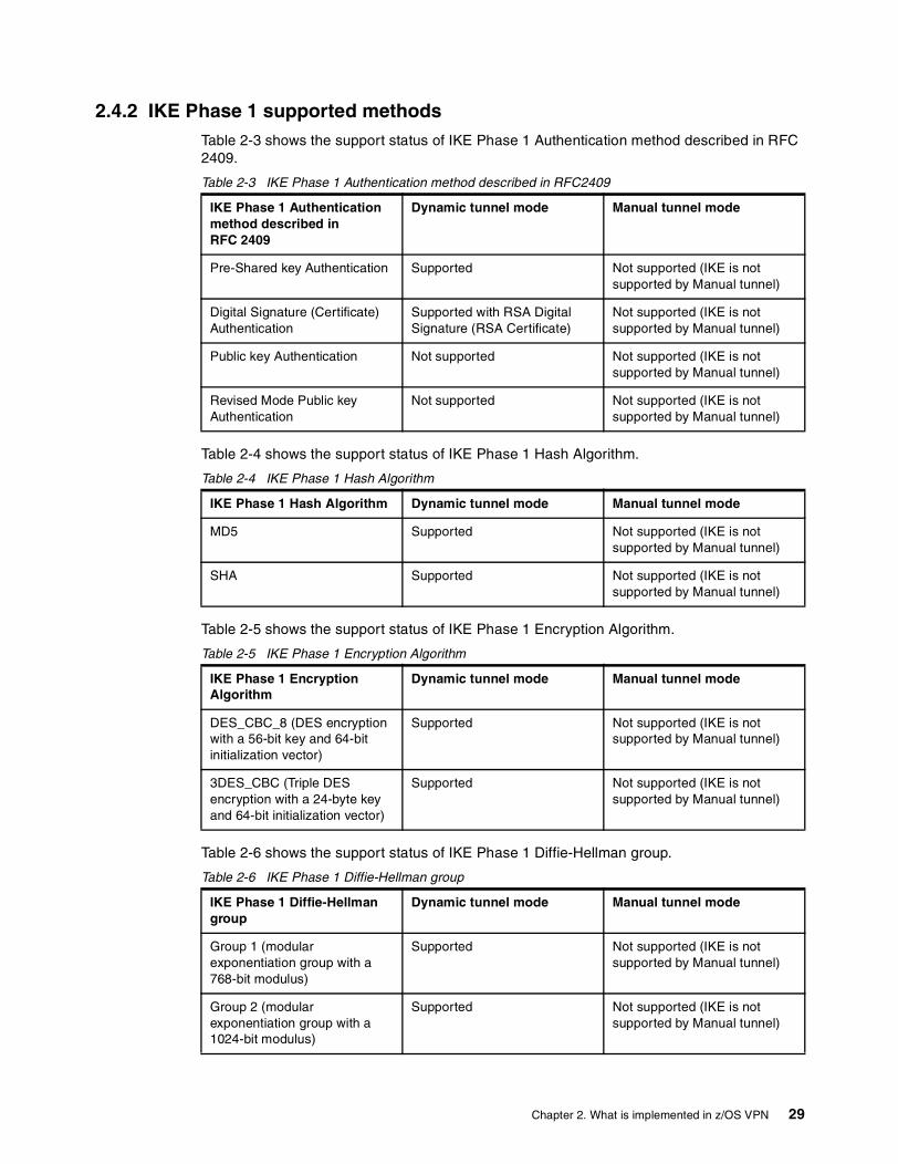
2.4.2 IKE Phase 1 supported methodsTable 2-3 shows the support status of IKE Phase 1 Authentication method described in RFC 2409.
Table 2-3 IKE Phase 1 Authentication method described in RFC2409
Table 2-4 shows the support status of IKE Phase 1 Hash Algorithm.
Table 2-4 IKE Phase 1 Hash Algorithm
Table 2-5 shows the support status of IKE Phase 1 Encryption Algorithm.
Table 2-5 IKE Phase 1 Encryption Algorithm
Table 2-6 shows the support status of IKE Phase 1 Diffie-Hellman group.
Table 2-6 IKE Phase 1 Diffie-Hellman group
IKE Phase 1 Authentication method described in RFC 2409
Dynamic tunnel mode Manual tunnel mode
Pre-Shared key Authentication Supported Not supported (IKE is not supported by Manual tunnel)
Digital Signature (Certificate) Authentication
Supported with RSA Digital Signature (RSA Certificate)
Not supported (IKE is not supported by Manual tunnel)
Public key Authentication Not supported Not supported (IKE is not supported by Manual tunnel)
Revised Mode Public key Authentication
Not supported Not supported (IKE is not supported by Manual tunnel)
IKE Phase 1 Hash Algorithm Dynamic tunnel mode Manual tunnel mode
MD5 Supported Not supported (IKE is not supported by Manual tunnel)
SHA Supported Not supported (IKE is not supported by Manual tunnel)
IKE Phase 1 Encryption Algorithm
Dynamic tunnel mode Manual tunnel mode
DES_CBC_8 (DES encryptionwith a 56-bit key and 64-bitinitialization vector)
Supported Not supported (IKE is not supported by Manual tunnel)
3DES_CBC (Triple DES encryption with a 24-byte key and 64-bit initialization vector)
Supported Not supported (IKE is not supported by Manual tunnel)
IKE Phase 1 Diffie-Hellman group
Dynamic tunnel mode Manual tunnel mode
Group 1 (modularexponentiation group with a768-bit modulus)
Supported Not supported (IKE is not supported by Manual tunnel)
Group 2 (modular exponentiation group with a 1024-bit modulus)
Supported Not supported (IKE is not supported by Manual tunnel)
Chapter 2. What is implemented in z/OS VPN 29
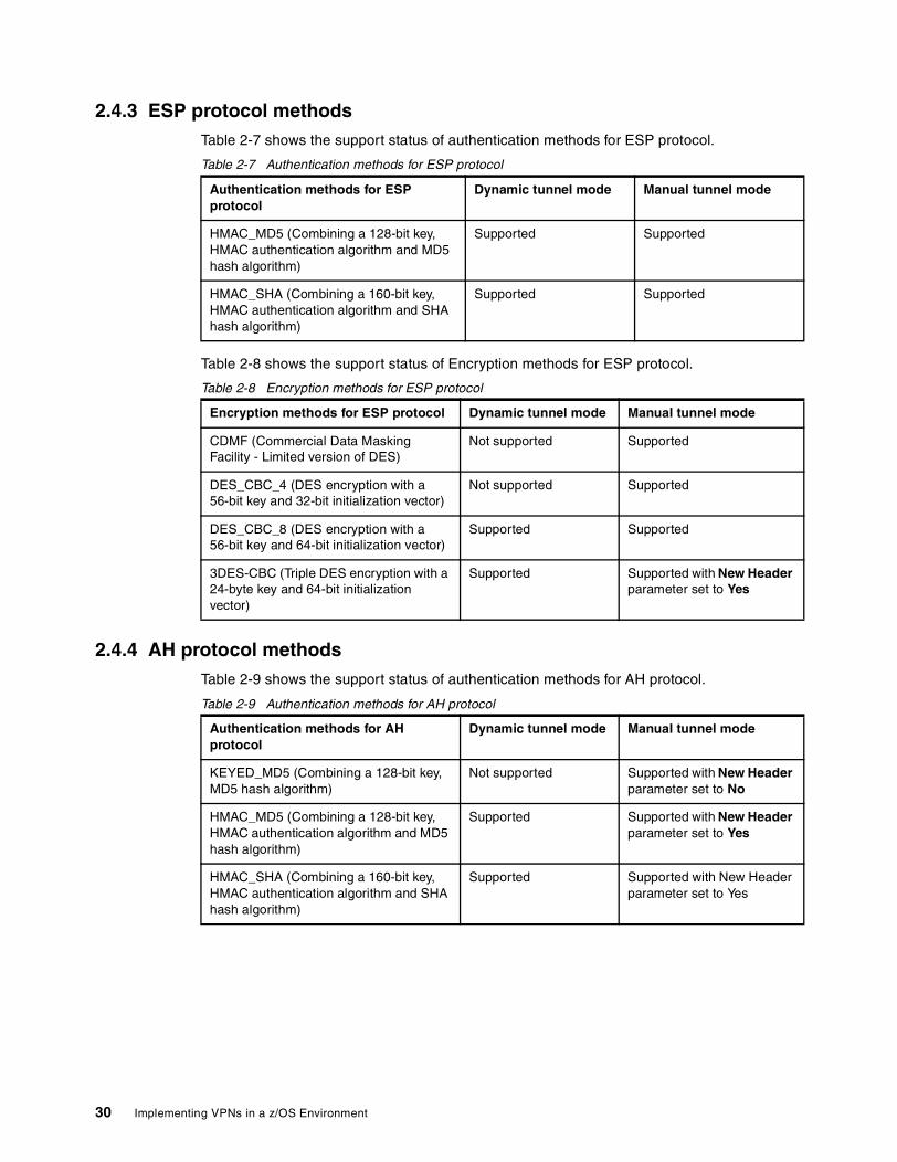
2.4.3 ESP protocol methodsTable 2-7 shows the support status of authentication methods for ESP protocol.
Table 2-7 Authentication methods for ESP protocol
Table 2-8 shows the support status of Encryption methods for ESP protocol.
Table 2-8 Encryption methods for ESP protocol
2.4.4 AH protocol methodsTable 2-9 shows the support status of authentication methods for AH protocol.
Table 2-9 Authentication methods for AH protocol
Authentication methods for ESP protocol
Dynamic tunnel mode Manual tunnel mode
HMAC_MD5 (Combining a 128-bit key, HMAC authentication algorithm and MD5 hash algorithm)
Supported Supported
HMAC_SHA (Combining a 160-bit key, HMAC authentication algorithm and SHA hash algorithm)
Supported Supported
Encryption methods for ESP protocol Dynamic tunnel mode Manual tunnel mode
CDMF (Commercial Data Masking Facility - Limited version of DES)
Not supported Supported
DES_CBC_4 (DES encryption with a 56-bit key and 32-bit initialization vector)
Not supported Supported
DES_CBC_8 (DES encryption with a56-bit key and 64-bit initialization vector)
Supported Supported
3DES-CBC (Triple DES encryption with a 24-byte key and 64-bit initialization vector)
Supported Supported with New Header parameter set to Yes
Authentication methods for AH protocol
Dynamic tunnel mode Manual tunnel mode
KEYED_MD5 (Combining a 128-bit key, MD5 hash algorithm)
Not supported Supported with New Header parameter set to No
HMAC_MD5 (Combining a 128-bit key, HMAC authentication algorithm and MD5 hash algorithm)
Supported Supported with New Header parameter set to Yes
HMAC_SHA (Combining a 160-bit key, HMAC authentication algorithm and SHA hash algorithm)
Supported Supported with New Header parameter set to Yes
30 Implementing VPNs in a z/OS Environment

Chapter 3. VPN planning and design
This chapter describes planning and design considerations, as well as the various tasks required to implement a VPN with z/OS. This chapter is intended to help you find a VPN solution that best fits your environment, including topology and protocols.
We introduce two flowcharts to assist in the planning process. They will guide you through the VPN design process, and provide you with the necessary information. The “Data management planning flowchart” on page 32 will help you define the protocols and parameters for IPSec VPN. If you decided to use dynamic VPNs, the “Key management planning flowchart” on page 43 will help you define the parameters for key exchanging.
The subsequent sections discuss:
� VPN considerations
� Topology planning suggestions and considerations
� Risk assessment suggestions and considerations
� Business case examples
3
© Copyright IBM Corp. 2002 31

3.1 VPN planning and design considerationsWhen planning a VPN, you must consider certain criteria. We show two flowcharts with the key items you have to evaluate and their respective sequence for each situation. Each step and decision is explained immediately following the flowcharts. We try to match the most common costumer requirements for three typical business situations: VPN connection of a headquarters office to a branch office, VPN connection between a remote user and a central office, and connection between two business partners.
Worksheets are provided in Appendix A, “VPN configuration worksheets” on page 147 to help you document your VPN configuration.
First of all, you must be very familiar with your network environment and requirements such as security, risk, and performance needs. You must decide on the kind of traffic you want to protect, since different policies can be applied to different traffic types.
3.2 Data management planning flowchartThe data management planning flowchart in Figure 3-1 on page 33 is intended to help you while planning your VPN topology and configurable parameters. We provide an explanation for every step you will take and every decision you will have to make immediately following the flowchart. For more detailed information about the involved protocols and algorithms, refer to the previous two chapters.
32 Implementing VPNs in a z/OS Environment
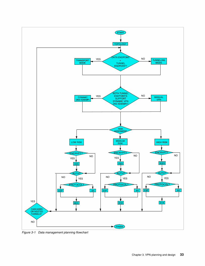
Figure 3-1 Data management planning flowchart
START
TUNNELINGMODE
TRANSPORTMODE
TOPOLOGY
DATA ENDPOINT=
TUNNELENDPOINT?
YES NO
CASCADEDOR NESTEDTUNNELS?
FINISH
YES
NO
LOW RISK
RISKASSESMENT
HIGH RISKMEDIUM
RISK
DES
ENCRYPT?
YESNO
3DES
ENCRYPT?
DES
ESP
ENCRYPT?
AUTH?
YES
NO
NO
YES
NO
MANUALVPN
DYNAMIC(IKE-ISAKMP)
BOTH TUNNELENDPOINTSSUPPORT
DYNAMIC VPN(IKE-ISAKMP)?
YES NO
PROTOCOL?
AH
MD5
ESP
AUTH?
NOYES
PROTOCOL?
AH
SHA
ESP
AUTH?
NOYES
PROTOCOL?
AH
SHA
Chapter 3. VPN planning and design 33
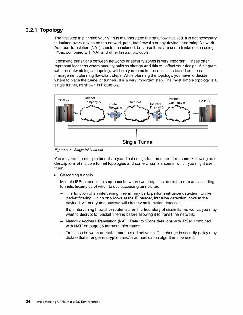
3.2.1 TopologyThe first step in planning your VPN is to understand the data flow involved. It is not necessary to include every device on the network path, but firewalls or any device performing Network Address Translation (NAT) should be included, because there are some limitations in using IPSec combined with NAT and other firewall protocols.
Identifying transitions between networks or security zones is very important. These often represent locations where security policies change and this will affect your design. A diagram with the network logical topology will help you to make the decisions based on the data management planning flowchart steps. While planning the topology, you have to decide where to place the tunnel or tunnels. It is a very important step. The most simple topology is a single tunnel, as shown in Figure 3-2.
Figure 3-2 Single VPN tunnel
You may require multiple tunnels in your final design for a number of reasons. Following are descriptions of multiple tunnel topologies and some circumstances in which you might use them.
� Cascading tunnels
Multiple IPSec tunnels in sequence between two endpoints are referred to as cascading tunnels. Examples of when to use cascading tunnels are:
– The function of an intervening firewall may be to perform intrusion detection. Unlike packet filtering, which only looks at the IP header, intrusion detection looks at the payload. An encrypted payload will circumvent intrusion detection.
– If an intervening firewall or router sits on the boundary of dissimilar networks, you may want to decrypt for packet filtering before allowing it to transit the network.
– Network Address Translation (NAT). Refer to “Considerations with IPSec combined with NAT” on page 35 for more information.
– Transition between untrusted and trusted networks. The change in security policy may dictate that stronger encryption and/or authentication algorithms be used.
IntranetCompany A
IntranetCompany BInternet
Host A Host BRouter /Firewall A
Single Tunnel
Router /Firewall B
34 Implementing VPNs in a z/OS Environment
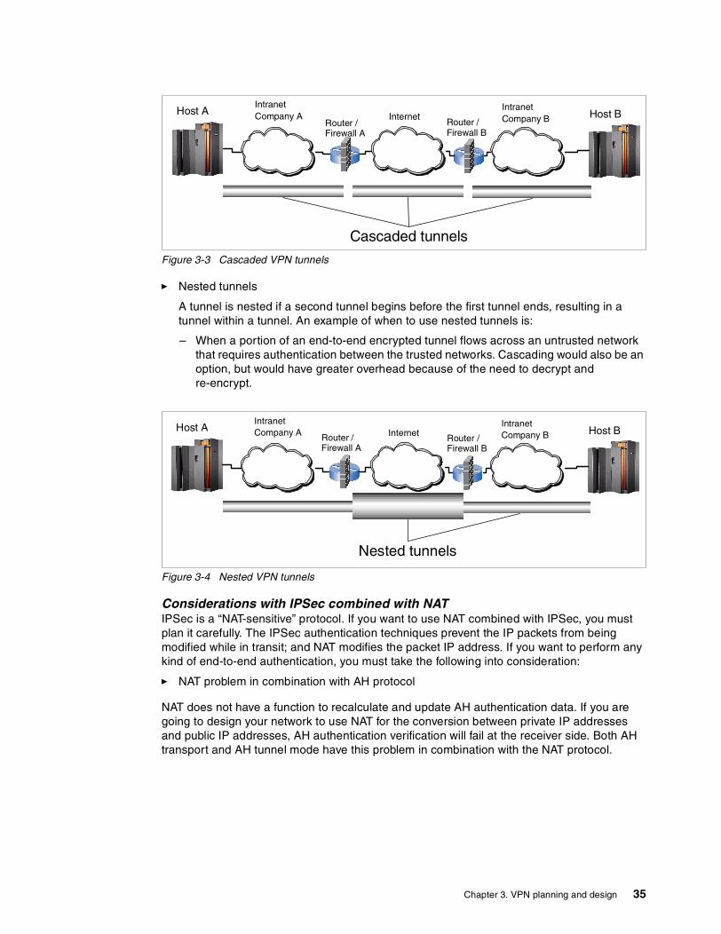
Figure 3-3 Cascaded VPN tunnels
� Nested tunnels
A tunnel is nested if a second tunnel begins before the first tunnel ends, resulting in a tunnel within a tunnel. An example of when to use nested tunnels is:
– When a portion of an end-to-end encrypted tunnel flows across an untrusted network that requires authentication between the trusted networks. Cascading would also be an option, but would have greater overhead because of the need to decrypt and re-encrypt.
Figure 3-4 Nested VPN tunnels
Considerations with IPSec combined with NATIPSec is a “NAT-sensitive” protocol. If you want to use NAT combined with IPSec, you must plan it carefully. The IPSec authentication techniques prevent the IP packets from being modified while in transit; and NAT modifies the packet IP address. If you want to perform any kind of end-to-end authentication, you must take the following into consideration:
� NAT problem in combination with AH protocol
NAT does not have a function to recalculate and update AH authentication data. If you are going to design your network to use NAT for the conversion between private IP addresses and public IP addresses, AH authentication verification will fail at the receiver side. Both AH transport and AH tunnel mode have this problem in combination with the NAT protocol.
IntranetCompany A
IntranetCompany BInternetHost A Host B
Router /Firewall A
Cascaded tunnels
Router /Firewall B
IntranetCompany A
IntranetCompany BInternetHost A Host B
Router /Firewall B
Nested tunnels
Router /Firewall A
Chapter 3. VPN planning and design 35
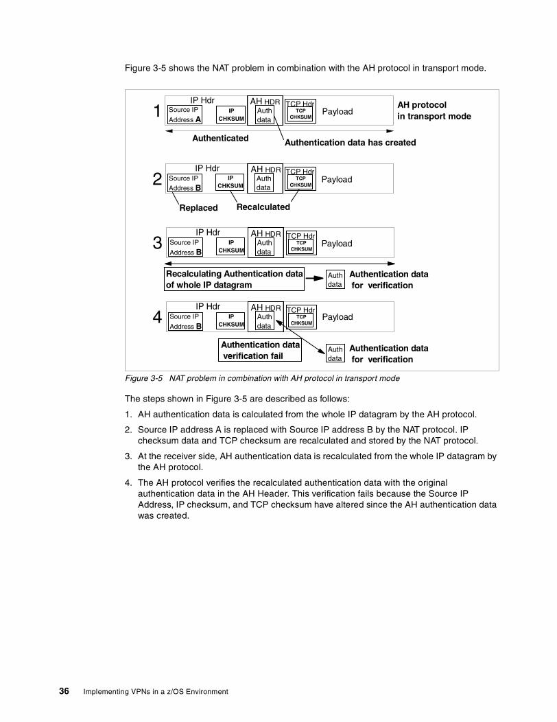
Figure 3-5 shows the NAT problem in combination with the AH protocol in transport mode.
Figure 3-5 NAT problem in combination with AH protocol in transport mode
The steps shown in Figure 3-5 are described as follows:
1. AH authentication data is calculated from the whole IP datagram by the AH protocol.
2. Source IP address A is replaced with Source IP address B by the NAT protocol. IP checksum data and TCP checksum are recalculated and stored by the NAT protocol.
3. At the receiver side, AH authentication data is recalculated from the whole IP datagram by the AH protocol.
4. The AH protocol verifies the recalculated authentication data with the original authentication data in the AH Header. This verification fails because the Source IP Address, IP checksum, and TCP checksum have altered since the AH authentication data was created.
IP HdrPayload
Authenticated
IPCHKSUM
Source IP
Address A
IP HdrPayloadIP
CHKSUMSource IP
Address B
Recalculated
1
2AH HDR
Authdata
Authdata
Authentication data has created
Replaced
IP HdrPayloadIP
CHKSUMSource IP
Address B
Recalculating Authentication dataof whole IP datagram
3AH HDR
Authdata
Authdata
Authentication datafor verification
IP HdrPayloadIP
CHKSUMSource IP
Address B4
AH HDRAuthdata
Authdata
Authentication datafor verification
Authentication dataverification fail
TCPCHKSUM
TCP Hdr AH protocolin transport mode
TCPCHKSUM
TCP Hdr
TCPCHKSUM
TCP Hdr
TCPCHKSUM
TCP Hdr
AH HDR
36 Implementing VPNs in a z/OS Environment
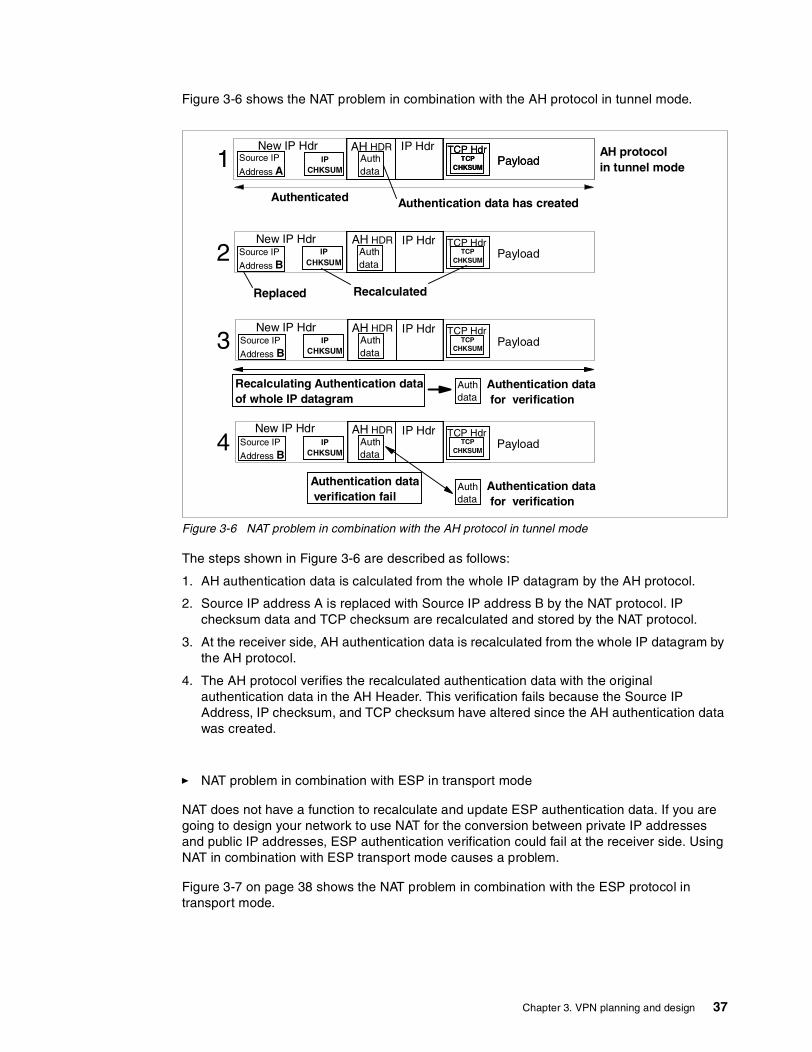
Figure 3-6 shows the NAT problem in combination with the AH protocol in tunnel mode.
Figure 3-6 NAT problem in combination with the AH protocol in tunnel mode
The steps shown in Figure 3-6 are described as follows:
1. AH authentication data is calculated from the whole IP datagram by the AH protocol.
2. Source IP address A is replaced with Source IP address B by the NAT protocol. IP checksum data and TCP checksum are recalculated and stored by the NAT protocol.
3. At the receiver side, AH authentication data is recalculated from the whole IP datagram by the AH protocol.
4. The AH protocol verifies the recalculated authentication data with the original authentication data in the AH Header. This verification fails because the Source IP Address, IP checksum, and TCP checksum have altered since the AH authentication data was created.
� NAT problem in combination with ESP in transport mode
NAT does not have a function to recalculate and update ESP authentication data. If you are going to design your network to use NAT for the conversion between private IP addresses and public IP addresses, ESP authentication verification could fail at the receiver side. Using NAT in combination with ESP transport mode causes a problem.
Figure 3-7 on page 38 shows the NAT problem in combination with the ESP protocol in transport mode.
Authenticated
IPCHKSUM
Source IP
Address B
Recalculated
2AH HDR
Authdata
Authentication data has created
Replaced
IPCHKSUM
Source IP
Address B
Recalculating Authentication dataof whole IP datagram
3AH HDR
Authdata
Authdata
Authentication datafor verification
IPCHKSUM
Source IP
Address B4
AH HDRAuthdata
Authdata
Authentication datafor verification
Authentication dataverification fail
AH protocolin tunnel mode
New IP HdrIP
CHKSUMSource IP
Address A1 Auth
dataPayloadTCP
CHKSUM
TCP HdrAH HDR IP Hdr
New IP Hdr
New IP Hdr
New IP Hdr
PayloadTCPCHKSUM
TCP Hdr
PayloadTCPCHKSUM
TCP HdrIP Hdr
IP Hdr
IP Hdr
PayloadTCPCHKSUM
TCP Hdr
PayloadTCPCHKSUM
TCP Hdr
Chapter 3. VPN planning and design 37

Figure 3-7 NAT problem in combination with ESP protocol in transport mode
The steps shown in Figure 3-7 are explained as follows:
1. ESP authentication data is calculated from the ESP Header, Payload, and ESP trailer by the ESP protocol.
2. Source IP address A is replaced with Source IP address B by the NAT protocol. The IP checksum data is recalculated and stored by the NAT protocol. TCP checksum cannot be recalculated and stored because the Payload which includes the TCP Header is encrypted.
3. At the receiver side, ESP authentication data is recalculated from the ESP Header, Payload, and ESP trailer by the ESP protocol.
4. The ESP protocol verifies the recalculated authentication data with the original authentication data in ESP Auth. This verification is done without error; however, TCP checksum verification fails because TCP checksum was not updated even though the Source IP address was altered.
The solution to these problems is to perform NAT before encryption and authentication. If you want to ensure authentication from end to end, you can break up your network into different segments. That is, you should use cascaded tunnels, performing NAT in decrypted packets only. Depending on your equipment, you can use the same device to decrypt the packet, NAT it, and then encrypt it again, as shown in Figure 3-8 on page 39.
Replaced
Recalculating Authentication dataof whole IP datagram
Authdata
Authentication datafor verification
Authentication dataverification OK
TCP checksumverification failsbecause TCP checksumwas not updated due tothe encryption
Source IP
Address A
Source IP
Address B
IP HdrIP
CHKSUM2 Auth
dataPayloadTCP
CHKSUM
TCP HdrESPHDR
ESPTRL
ESPAUTHESPHDR
Encrypted Authentication data was created
ESP protocolin transport mode
IP HdrIP
CHKSUM1 Auth
dataPayloadTCP
CHKSUM
TCP HdrESPHDR
ESPTRL
ESPAUTHESPHDR
Authenticated
Source IP
Address B
IP HdrIP
CHKSUM3 Auth
dataPayloadTCP
CHKSUM
TCP HdrESPHDR
ESPTRL
ESPAUTHESPHDR
Source IP
Address B
IP HdrIP
CHKSUM4 Auth
dataPayloadTCP
CHKSUM
TCP HdrESPHDR
ESPTRL
ESPAUTHESPHDR
Recalculated Not Recalculatedbecause Payload is encrypted
Authdata
Authentication datafor verification
38 Implementing VPNs in a z/OS Environment
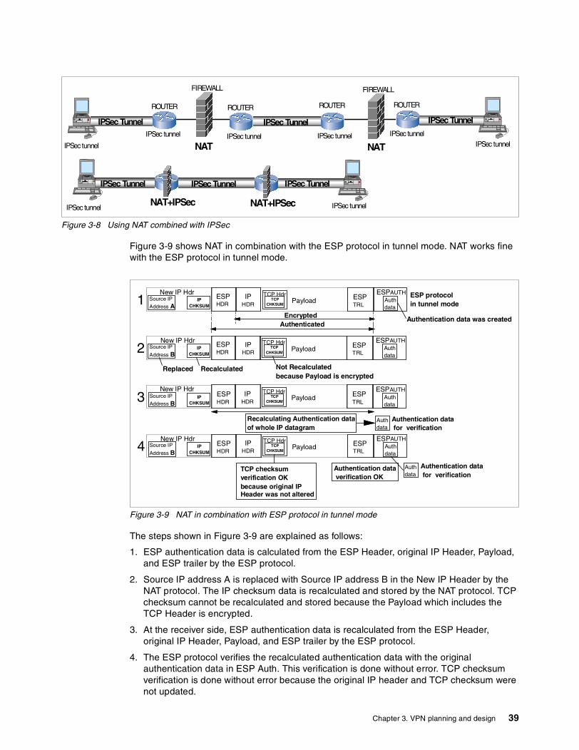
Figure 3-8 Using NAT combined with IPSec
Figure 3-9 shows NAT in combination with the ESP protocol in tunnel mode. NAT works fine with the ESP protocol in tunnel mode.
Figure 3-9 NAT in combination with ESP protocol in tunnel mode
The steps shown in Figure 3-9 are explained as follows:
1. ESP authentication data is calculated from the ESP Header, original IP Header, Payload, and ESP trailer by the ESP protocol.
2. Source IP address A is replaced with Source IP address B in the New IP Header by the NAT protocol. The IP checksum data is recalculated and stored by the NAT protocol. TCP checksum cannot be recalculated and stored because the Payload which includes the TCP Header is encrypted.
3. At the receiver side, ESP authentication data is recalculated from the ESP Header, original IP Header, Payload, and ESP trailer by the ESP protocol.
4. The ESP protocol verifies the recalculated authentication data with the original authentication data in ESP Auth. This verification is done without error. TCP checksum verification is done without error because the original IP header and TCP checksum were not updated.
IPSec Tunnel
ROUTERROUTERROUTER
FIREWALL FIREWALL
IPSec TunnelIPSec Tunnel
ROUTER
NAT NATIPSec tunnel
IPSectunnelIPSec tunnel IPSec tunnel IPSec tunnel
IPSec tunnel
IPSec Tunnel IPSec TunnelIPSec Tunnel
NAT+IPSecIPSec tunnel NAT+IPSec IPSec tunnel
Recalculating Authentication dataof whole IP datagram
Authdata
Authentication datafor verification
Authentication dataverification OK
Authdata
PayloadTCPCHKSUM
TCP Hdr ESPTRL
ESPAUTH
Encrypted Authentication data was created
ESP protocolin tunnel mode
Source IP
Address A
New IP HdrIP
CHKSUM1 Auth
dataPayloadTCP
CHKSUM
TCP Hdr ESPTRL
ESPAUTHESPHDR
Authenticated
Authdata
PayloadTCPCHKSUM
TCP Hdr ESPTRL
ESPAUTH
Authdata
PayloadTCPCHKSUM
TCP Hdr ESPTRL
ESPAUTH
Recalculated Not Recalculatedbecause Payload is encrypted
Authdata
Authentication datafor verification
TCP checksumverification OKbecause original IPHeader was not altered
Replaced
Source IP
Address BIP
CHKSUM2
New IP Hdr
Source IP
Address BIP
CHKSUM3
New IP Hdr
Source IP
Address BIP
CHKSUM4
New IP Hdr
IPHDR
ESPHDR
ESPHDR
ESPHDR
IPHDR
IPHDR
IPHDR
Chapter 3. VPN planning and design 39
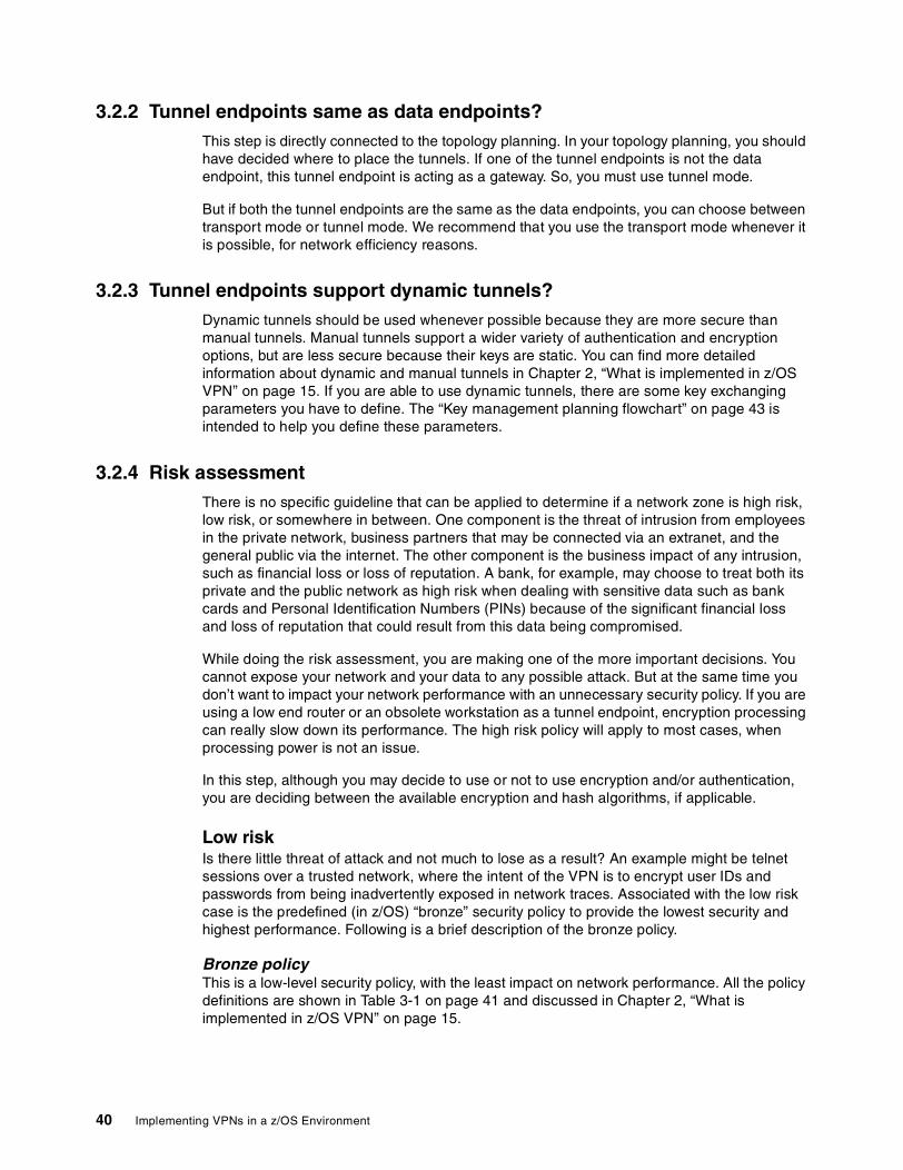
3.2.2 Tunnel endpoints same as data endpoints?This step is directly connected to the topology planning. In your topology planning, you should have decided where to place the tunnels. If one of the tunnel endpoints is not the data endpoint, this tunnel endpoint is acting as a gateway. So, you must use tunnel mode.
But if both the tunnel endpoints are the same as the data endpoints, you can choose between transport mode or tunnel mode. We recommend that you use the transport mode whenever it is possible, for network efficiency reasons.
3.2.3 Tunnel endpoints support dynamic tunnels?Dynamic tunnels should be used whenever possible because they are more secure than manual tunnels. Manual tunnels support a wider variety of authentication and encryption options, but are less secure because their keys are static. You can find more detailed information about dynamic and manual tunnels in Chapter 2, “What is implemented in z/OS VPN” on page 15. If you are able to use dynamic tunnels, there are some key exchanging parameters you have to define. The “Key management planning flowchart” on page 43 is intended to help you define these parameters.
3.2.4 Risk assessmentThere is no specific guideline that can be applied to determine if a network zone is high risk, low risk, or somewhere in between. One component is the threat of intrusion from employees in the private network, business partners that may be connected via an extranet, and the general public via the internet. The other component is the business impact of any intrusion, such as financial loss or loss of reputation. A bank, for example, may choose to treat both its private and the public network as high risk when dealing with sensitive data such as bank cards and Personal Identification Numbers (PINs) because of the significant financial loss and loss of reputation that could result from this data being compromised.
While doing the risk assessment, you are making one of the more important decisions. You cannot expose your network and your data to any possible attack. But at the same time you don’t want to impact your network performance with an unnecessary security policy. If you are using a low end router or an obsolete workstation as a tunnel endpoint, encryption processing can really slow down its performance. The high risk policy will apply to most cases, when processing power is not an issue.
In this step, although you may decide to use or not to use encryption and/or authentication, you are deciding between the available encryption and hash algorithms, if applicable.
Low riskIs there little threat of attack and not much to lose as a result? An example might be telnet sessions over a trusted network, where the intent of the VPN is to encrypt user IDs and passwords from being inadvertently exposed in network traces. Associated with the low risk case is the predefined (in z/OS) “bronze” security policy to provide the lowest security and highest performance. Following is a brief description of the bronze policy.
Bronze policyThis is a low-level security policy, with the least impact on network performance. All the policy definitions are shown in Table 3-1 on page 41 and discussed in Chapter 2, “What is implemented in z/OS VPN” on page 15.
40 Implementing VPNs in a z/OS Environment
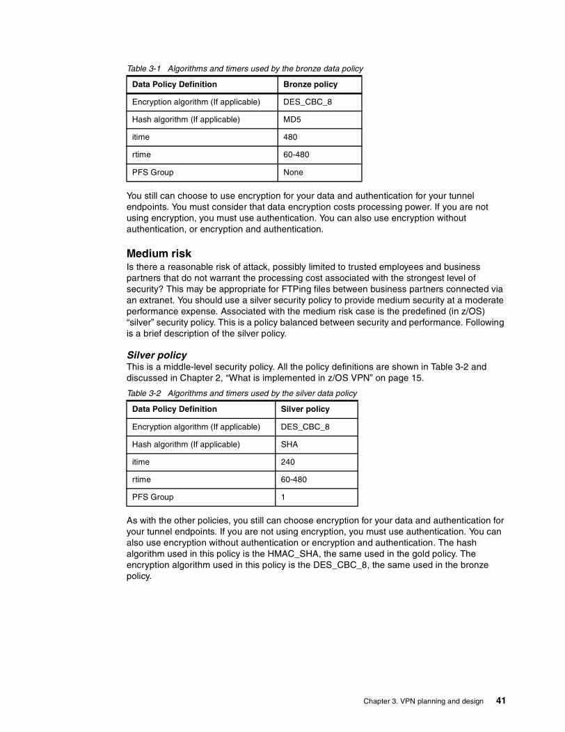
Table 3-1 Algorithms and timers used by the bronze data policy
You still can choose to use encryption for your data and authentication for your tunnel endpoints. You must consider that data encryption costs processing power. If you are not using encryption, you must use authentication. You can also use encryption without authentication, or encryption and authentication.
Medium riskIs there a reasonable risk of attack, possibly limited to trusted employees and business partners that do not warrant the processing cost associated with the strongest level of security? This may be appropriate for FTPing files between business partners connected via an extranet. You should use a silver security policy to provide medium security at a moderate performance expense. Associated with the medium risk case is the predefined (in z/OS) “silver” security policy. This is a policy balanced between security and performance. Following is a brief description of the silver policy.
Silver policyThis is a middle-level security policy. All the policy definitions are shown in Table 3-2 and discussed in Chapter 2, “What is implemented in z/OS VPN” on page 15.
Table 3-2 Algorithms and timers used by the silver data policy
As with the other policies, you still can choose encryption for your data and authentication for your tunnel endpoints. If you are not using encryption, you must use authentication. You can also use encryption without authentication or encryption and authentication. The hash algorithm used in this policy is the HMAC_SHA, the same used in the gold policy. The encryption algorithm used in this policy is the DES_CBC_8, the same used in the bronze policy.
Data Policy Definition Bronze policy
Encryption algorithm (If applicable) DES_CBC_8
Hash algorithm (If applicable) MD5
itime 480
rtime 60-480
PFS Group None
Data Policy Definition Silver policy
Encryption algorithm (If applicable) DES_CBC_8
Hash algorithm (If applicable) SHA
itime 240
rtime 60-480
PFS Group 1
Chapter 3. VPN planning and design 41

High riskIs there a significant risk of attack or substantial impact associated that warrants the strongest level of security? Network connections over the Internet or extremely sensitive data over a trusted network would be good examples of high risk situations. Do you have enough processing power or a co-processing card in both tunnel end points to handle the encryption requirements? Associated with the high risk case is the predefined (in z/OS) “gold” security policy, which provides the highest security and lowest performance. This policy can cause significant performance impact depending on your system.
Gold policyThis is a high-level security policy. All the policy definitions are shown in Table 3-3 and discussed in Chapter 2, “What is implemented in z/OS VPN” on page 15.
Table 3-3 Algorithms and timers used by the gold data policy
Although we do not recommend it, you still can choose not to encrypt your data and not to authenticate your tunnel endpoints. With this policy, we strongly suggest that you use encryption and authentication. If it is not possible, you should at least use encryption. The encryption algorithm used in this policy is the 3DES_CBC and the hash algorithm used in this policy is the HMAC_SHA.
3.2.5 EncryptShould you encrypt the data being tunneled?
The encryption algorithm to be used depends on the security policy you adopted. If you do not want your data to be viewed in the Internet, you should encrypt it.
3.2.6 AuthenticateShould the tunnel endpoints authenticate to one another?
As with encryption, the algorithm to be used depends on the security policy you adopted. If you want to protect your network from hacker attacks, you should authenticate the tunnel endpoints.
3.2.7 ProtocolAs explained in “IPSec concept” on page 2, you can use the ESP or AH protocols (as well as both) to authenticate the tunnel endpoints. We recommend that you use the ESP protocol for authentication whenever possible. The AH protocol was developed in the first released IPSec RFCs, when the ESP provided only encryption, but not authentication; it is still being supported for compatibility reasons. You defined the hash algorithm to be used during the risk assessment process. If you are using a bronze policy, you will use the HMAC_MD5 as the hash algorithm. Otherwise, you will use the HMAC_SHA.
Data Policy Definition Bronze policy
Encryption algorithm (If applicable) 3DES_CBC
Hash algorithm (If applicable) SHA
itime 120
rtime 60-480
PFS Group 2
42 Implementing VPNs in a z/OS Environment

3.2.8 Cascading, nesting or mixed topology?If you decided to use nested or cascaded tunnels in the topology planning step of the flowchart, you have to go back to “Tunnel endpoints same as data endpoints?” on page 40 and follow all the flowchart steps for each tunnel you will implement.
3.3 Key management planning flowchartWe now introduce the key management planning flowchart. If both tunnel endpoints you are using support IKE (as described in Section 3.2.3, “Tunnel endpoints support dynamic tunnels?”, on page 40), you should follow the flowchart’s steps, otherwise proceed to Section 3.4, “Common scenarios”, on page 46. The flowchart in Figure 3-10 on page 44 is intended to help you to define the right key policies according to your environment.
An explanation of each step is provided following the flowchart.
Chapter 3. VPN planning and design 43
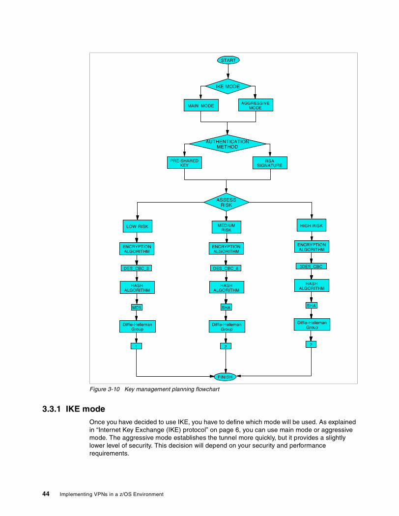
Figure 3-10 Key management planning flowchart
3.3.1 IKE modeOnce you have decided to use IKE, you have to define which mode will be used. As explained in “Internet Key Exchange (IKE) protocol” on page 6, you can use main mode or aggressive mode. The aggressive mode establishes the tunnel more quickly, but it provides a slightly lower level of security. This decision will depend on your security and performance requirements.
IKE MODE
START
AGGRESSIVEMODEMAIN MODE
HIGH RISKBRONZEPOLICY
SILVERPOLICY
ASSESSRISK
LOW RISK MEDIUMRISK
AUTHENTICATIONMETHOD
PRE-SHAREDKEY
RSASIGNATURE
ENCRYPTIONALGORITHM
DES_CBC_8
HASHALGORITHM
MD5
Diffie-HellemanGroup
1
ENCRYPTIONALGORITHM
DES_CBC_8
HASHALGORITHM
SHA
Diffie-HellemanGroup
2
ENCRYPTIONALGORITHM
3DES_CBC
HASHALGORITHM
SHA
Diffie-HellemanGroup
ENCRYPTIONALGORITHM
DES_CBC_8
HASHALGORITHM
SHA
Diffie-HellemanGroup
2
ENCRYPTIONALGORITHM
DES_CBC_8
HASHALGORITHM
SHA
Diffie-HellemanGroup
FINISH
44 Implementing VPNs in a z/OS Environment
3.3.2 Authentication methodThis step is the most important in the key management flowchart. You will now choose between a digital signature or a pre-shared key. The RSA digital signature provides a significantly higher level of security than the pre-shared key, as explained in “Internet Key Exchange (IKE) protocol” on page 6. You can use z/OS Security Server (RACF), described in “Digital certificates” on page 118, as your Certification Authority (CA).
3.3.3 Assess riskAlthough you can use a key management policy different than the data management policy, we recommend that you not do so. After choosing the security policy you want to use, you do not have to make any other decision for key management; each policy has its own protocol combination.
Low riskIf your network was assessed as low risk during “Risk assessment” on page 40, you should apply the bronze key policy.
Bronze policyThis is a low security and high performance policy. The protocols and timers used are shown in Table 3-4 and discussed in Chapter 2, “What is implemented in z/OS VPN” on page 15.
Table 3-4 Algorithms and timers used by the bronze key policy
Medium riskIf your network was assessed as medium risk during “Risk assessment” on page 40, you should apply the silver key policy.
Silver policyThis is a policy balanced between security and performance. The protocols and timers used are shown in Table 3-5 and discussed in Chapter 2, “What is implemented in z/OS VPN” on page 15.
Table 3-5 Algorithms and timers used by the silver key policy
Key Policy Definition Bronze policy
Encryption algorithm DES_CBC_8
Hash algorithm MD5
Diffie-Hellman Group 1
itime 1440
rtime 60-1440
Key Policy Definition Bronze policy
Encryption algorithm DES_CBC_8
Hash algorithm SHA
Diffie-Hellman Group 2
itime 960
rtime 60-1440
Chapter 3. VPN planning and design 45
High riskIf your network was assessed as high risk during “Risk assessment” on page 40, you should apply the gold key policy.
Gold policyThis is a high security and low performance policy. The protocols and timers used are shown in Table 3-6 and discussed in Chapter 2, “What is implemented in z/OS VPN” on page 15.
Table 3-6 Algorithms and timers used by the gold key policy
3.4 Common scenariosIn this section we describe the three most likely business scenarios suited for the implementation of a VPN solution. This material is intended to help you define the best security policy to fit your topology. It provides a general discussion of these common scenarios. For a complete example of how to configure the z/OS Firewall technologies, using the configuration client GUI, refer to Chapter 5, “Data management and key management configuration” on page 79.
The scenarios are also used to walk you through the flowcharts.
You have to define a security policy to your network based on how sensitive your data is. Two equal networks may require different security policies if the data is not the same. For example, if your environment is a bank local network and your data is PIN numbers and user account information, you will have to use a policy with the highest level of security even if you have a strict policy to control physical access to the network. But if your environment is a corporate local network where you have a secure policy to control physical access to the network and your data is not so sensitive as the bank data (such as personal e-mail access, for example) you may use a policy with the lowest level of security just to ensure that outsiders will not have access to your employees’ personal e-mails.
3.4.1 Branch office connectionSuppose that your company is looking for a more cost-effective solution for connecting a branch office to it‘s headquarters. Instead of using leased lines or frame relay links, you decided to use a VPN solution.
In a scenario like this, you may want to connect the two intranets, joining them together and providing access to all users in both sites. At the same time, you want to protect your network from being intruded on by a non-authorized person and protect your data from being viewed by other people in the Internet.
Key Policy Definition Gold policy
Encryption algorithm 3DES_CBC
Hash algorithm SHA
Diffie-Hellman Group 2
itime 480
rtime 60-1440
46 Implementing VPNs in a z/OS Environment

To protect your network from intrusions, you should implement a firewall with the correct policies for your network boundary. To protect your data from being viewed on the Internet, you should use encryption between the two gateways. This would be a gateway-to-gateway VPN topology.
Figure 3-11 depicts the applicable network topology. In the following discussion we apply the questions from both flowcharts to this scenario.
Figure 3-11 Example of connection between corporate headquarters and branch office.
We start with the “Data management planning flowchart” on page 32.
� The first step is to define the topology to be used. In this case, we decided to use a gateway-to-gateway topology because we want to provide access to the users in the intranets located behind two z/OS servers, as shown in Figure 3-11.
� The data endpoint is not always the tunnel endpoint because we can have a workstation in one intranet communicating with a workstation in the other intranet. In this case, the two workstations are the data endpoints and the two z/OS servers are the tunnel endpoints. So, we must use tunnel mode.
� The next step is to decide between manual and dynamic VPN. We are using the two z/OS servers as the tunnel endpoints and they do support IKE. So, we will use dynamic VPN because it provides a higher security level and is easier to maintain. Once we decide on dynamic VPN, we have to follow the key management flowchart steps. We will do it after finishing the current flowchart.
� Assessing the risk is the most important decision. In this case, we are not using NAT and we are using the internet as a network media, so we will use a high risk policy. The pre-defined security policy associated with this risk level is the gold policy.
� Although our data is not highly sensitive, we do not want it to be viewable as plain text by anyone taking a trace on the internet. So, we are going to use encryption. As defined with the gold policy, we will be using the 3DES algorithm for encryption.
� For prevention of malicious hacker attacks through the Internet, we will use ESP authentication. The algorithm used for authentication in the gold policy is the HMAC_SHA.
� We are using only one tunnel, which starts in one z/OS server and ends in the other. We are not using nested or cascaded tunnels so the data management planning is complete.
We now follow the steps defined by the “Key management planning flowchart” on page 43.
� The first step here is to define the IKE mode. You can choose between aggressive mode and main mode. The main mode provides a higher level of security, but takes more time to set up the tunnel. According to our security requirements for this example, we chose the main mode.
� Now we need to define the authentication method to be used. The options are to use pre-shared key or RSA digital signatures. We are going to use the pre-shared key because it is easy to implement, but it is important to know that we are assuming some risk by using a less secure authentication method.
INTERNET EXTRANET
IPSec Tunnel
EXTRANETCORPORATEINTRANET
BRANCHOFFICEINTRANET
Client
ROUTER /FIREWALL
ROUTER /FIREWALL
z/OSGATEWAY
z/OSGATEWAY
Chapter 3. VPN planning and design 47
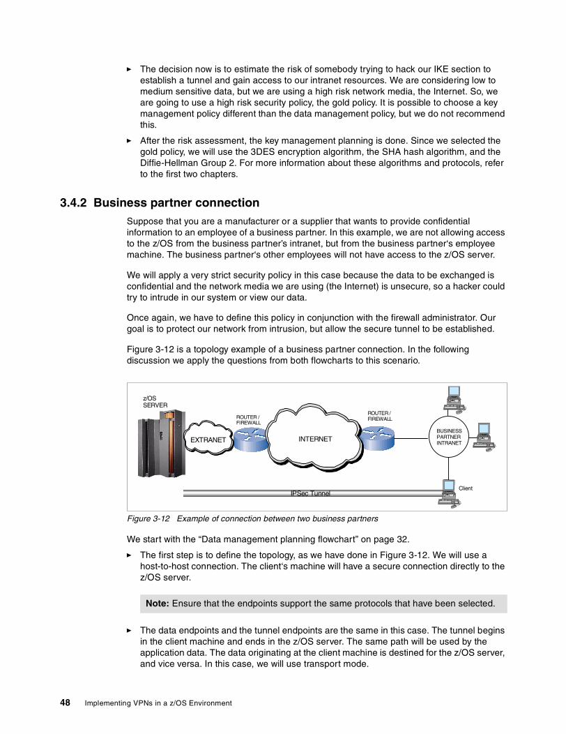
� The decision now is to estimate the risk of somebody trying to hack our IKE section to establish a tunnel and gain access to our intranet resources. We are considering low to medium sensitive data, but we are using a high risk network media, the Internet. So, we are going to use a high risk security policy, the gold policy. It is possible to choose a key management policy different than the data management policy, but we do not recommend this.
� After the risk assessment, the key management planning is done. Since we selected the gold policy, we will use the 3DES encryption algorithm, the SHA hash algorithm, and the Diffie-Hellman Group 2. For more information about these algorithms and protocols, refer to the first two chapters.
3.4.2 Business partner connectionSuppose that you are a manufacturer or a supplier that wants to provide confidential information to an employee of a business partner. In this example, we are not allowing access to the z/OS from the business partner’s intranet, but from the business partner‘s employee machine. The business partner‘s other employees will not have access to the z/OS server.
We will apply a very strict security policy in this case because the data to be exchanged is confidential and the network media we are using (the Internet) is unsecure, so a hacker could try to intrude in our system or view our data.
Once again, we have to define this policy in conjunction with the firewall administrator. Our goal is to protect our network from intrusion, but allow the secure tunnel to be established.
Figure 3-12 is a topology example of a business partner connection. In the following discussion we apply the questions from both flowcharts to this scenario.
Figure 3-12 Example of connection between two business partners
We start with the “Data management planning flowchart” on page 32.
� The first step is to define the topology, as we have done in Figure 3-12. We will use a host-to-host connection. The client‘s machine will have a secure connection directly to the z/OS server.
� The data endpoints and the tunnel endpoints are the same in this case. The tunnel begins in the client machine and ends in the z/OS server. The same path will be used by the application data. The data originating at the client machine is destined for the z/OS server, and vice versa. In this case, we will use transport mode.
Note: Ensure that the endpoints support the same protocols that have been selected.
INTERNET
IPSec Tunnel
BUSINESSPARTNERINTRANET
Client
ROUTER /FIREWALLROUTER /
FIREWALL
EXTRANET
z/OSSERVER
48 Implementing VPNs in a z/OS Environment
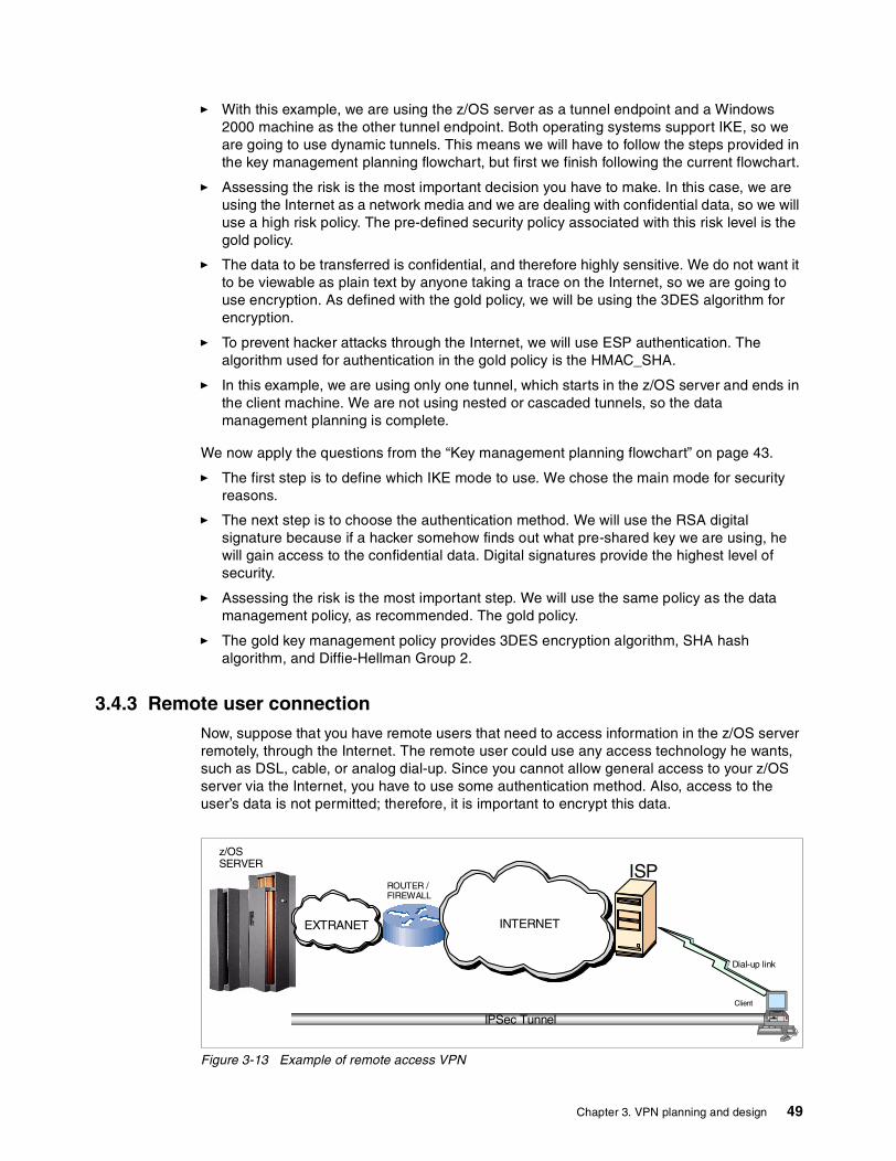
� With this example, we are using the z/OS server as a tunnel endpoint and a Windows 2000 machine as the other tunnel endpoint. Both operating systems support IKE, so we are going to use dynamic tunnels. This means we will have to follow the steps provided in the key management planning flowchart, but first we finish following the current flowchart.
� Assessing the risk is the most important decision you have to make. In this case, we are using the Internet as a network media and we are dealing with confidential data, so we will use a high risk policy. The pre-defined security policy associated with this risk level is the gold policy.
� The data to be transferred is confidential, and therefore highly sensitive. We do not want it to be viewable as plain text by anyone taking a trace on the Internet, so we are going to use encryption. As defined with the gold policy, we will be using the 3DES algorithm for encryption.
� To prevent hacker attacks through the Internet, we will use ESP authentication. The algorithm used for authentication in the gold policy is the HMAC_SHA.
� In this example, we are using only one tunnel, which starts in the z/OS server and ends in the client machine. We are not using nested or cascaded tunnels, so the data management planning is complete.
We now apply the questions from the “Key management planning flowchart” on page 43.
� The first step is to define which IKE mode to use. We chose the main mode for security reasons.
� The next step is to choose the authentication method. We will use the RSA digital signature because if a hacker somehow finds out what pre-shared key we are using, he will gain access to the confidential data. Digital signatures provide the highest level of security.
� Assessing the risk is the most important step. We will use the same policy as the data management policy, as recommended. The gold policy.
� The gold key management policy provides 3DES encryption algorithm, SHA hash algorithm, and Diffie-Hellman Group 2.
3.4.3 Remote user connectionNow, suppose that you have remote users that need to access information in the z/OS server remotely, through the Internet. The remote user could use any access technology he wants, such as DSL, cable, or analog dial-up. Since you cannot allow general access to your z/OS server via the Internet, you have to use some authentication method. Also, access to the user’s data is not permitted; therefore, it is important to encrypt this data.
Figure 3-13 Example of remote access VPN
INTERNET
IPSec Tunnel
ROUTER /FIREWALL
EXTRANET
z/OSSERVER ISP
Dial-up link
Client
Chapter 3. VPN planning and design 49

In the following discussion we apply the questions from both flowcharts to this scenario. We will start with the “Data management planning flowchart” on page 32.
� The first step is to define the topology, as in Figure 3-13. We will use a host-to-host connection. The client’s machine will have a secure connection directly to the z/OS server.
� The data endpoints and the tunnel endpoints are the same in this case. The tunnel begins in the client machine and ends in the z/OS server. The same path will be used by the application data. The data originating at the client machine is destined for the z/OS server, and vice versa. In this case, we will use transport mode.
� With this example, we are using the z/OS server as a tunnel endpoint and a Windows 2000 machine as the other tunnel endpoint. Both operating systems support IKE, so we are going to use dynamic tunnels. This means we will have to follow the steps provided in the key management planning flowchart, but first we finish following the current flowchart.
� Assessing the risk is the most important decision you have to make. In this case, we are using the Internet as a network media and we are dealing with confidential data, so we will use a high risk policy. The pre-defined security policy associated with this risk level is the gold policy.
� We do not want the data to be viewable as plain text by anyone taking a trace on the Internet, so we are going to use encryption. As defined with the gold policy, we will be using the 3DES algorithm for encryption.
� For prevention of malicious hacker attacks through the Internet, we will use ESP authentication. The algorithm used for authentication in the gold policy is the HMAC_SHA.
� In this example, we are using only one tunnel that starts in the z/OS server and ends in the client machine. We are not using nested or cascaded tunnels, so the data management planning is over.
We can now follow the “Key management planning flowchart” on page 43.
� The first step is to define which IKE mode to use. We chose main mode for security reasons.
� The next step is to choose the authentication method. We will use the RSA digital signature because if a hacker somehow finds out what pre-shared key we are using, he will gain access to the confidential data. Digital signatures provide the highest level of security.
� Assessing the risk is the most important step. We will use the same policy as the data management policy, the gold policy.
� The gold key management policy provides 3DES encryption algorithm, SHA hash algorithm, and Diffie-Hellman group 2.
Note: Ensure that the endpoints support the same protocols that have been selected.
50 Implementing VPNs in a z/OS Environment

Chapter 4. VPN pre-installation and implementaion
This chapter provides a list of the required software and hardware needed to implement VPN on z/OS V1R2. It also presents the actual steps we used for implementing the VPN in this book.
In this chapter, we describe how to do the following:
� Install and configure the z/OS firewall
� Configure the TCPIP on the firewall host
� Customize z/OS UNIX System Services and firewall startup
� Install and configure the Open Cryptographic Services Facility OCSF
� Install and configure the Open Cryptographic Enhanced Plug-ins (OCEP)
4
© Copyright IBM Corp. 2002 51
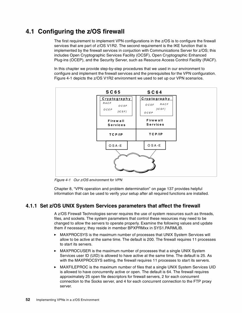
4.1 Configuring the z/OS firewallThe first requirement to implement VPN configurations in the z/OS is to configure the firewall services that are part of z/OS V1R2. The second requirement is the IKE function that is implemented by the firewall services in conjuction with Communications Server for z/OS; this includes Open Cryptographic Services Facility (OCSF), Open Cryptographic Enhanced Plug-ins (OCEP), and the Security Server, such as Resource Access Control Facility (RACF).
In this chapter we provide step-by-step procedures that we used in our environment to configure and implement the firewall services and the prerequisites for the VPN configuration. Figure 4-1 depicts the z/OS V1R2 environment we used to set up our VPN scenarios.
Figure 4-1 Our z/OS environment for VPN
Chapter 8, “VPN operation and problem determination” on page 137 provides helpful information that can be used to verify your setup after all required functions are installed.
4.1.1 Set z/OS UNIX System Services parameters that affect the firewallA z/OS Firewall Technologies server requires the use of system resources such as threads, files, and sockets. The system parameters that control these resources may need to be changed to allow the servers to operate properly. Examine the following values and update them if necessary; they reside in member BPXPRMxx in SYS1.PARMLIB.
� MAXPROCSYS is the maximum number of processes that UNIX System Services will allow to be active at the same time. The default is 200. The firewall requires 11 processes to start its servers.
� MAXPROCUSER is the maximum number of processes that a single UNIX System Services user ID (UID) is allowed to have active at the same time. The default is 25. As with the MAXPROCSYS setting, the firewall requires 11 processes to start its servers.
� MAXFILEPROC is the maximum number of files that a single UNIX System Services UID is allowed to have concurrently active or open. The default is 64. The firewall requires approximately 25 open file descriptors for firewall servers, 2 for each concurrent connection to the Socks server, and 4 for each concurrent connection to the FTP proxy server.
O S A -E O S A -E
T C P /IP T C P /IP
F ir e w a l lS e r v ic e s
F ir e w a l lS e r v ic e s
R A C FO C S F
O C E P
C r y p to g r a p h y
[ IC S F ]
R A C FO C S F
O C E P
C r y p to g r a p h y
[ IC S F ]
S C 6 5 S C 6 4
52 Implementing VPNs in a z/OS Environment
� MAXTHREADTASKS is the number of z/OS tasks created with pthread_create that a single user may have concurrently active in a process. The default is 50. The firewall requires approximately 10 threads for firewall servers, 1 thread for each concurrent connection to the Socks server, and 1 thread for each concurrent connection to the proxy FTP server.
� MAXTHREAD is the maximum number of threads created with pthread_create, including those that are running, queued, and exited but not detached, that a single server can have currently active. The default is 200. The Socks and proxy FTP servers require 1 thread for each concurrent connection.
� MAXSOCKETS is the maximum number of sockets that can be obtained for the given file system type. The default is 64. The firewall requires approximately 25 sockets for firewall servers, 2 for each concurrent connection to the Socks server, and 4 for each concurrent connection to the FTP proxy server.
Also you need to verify that the AF_UNIX and AF_INET are defined in the BPXPRMxx member of SYS1.PARMLIB.
If the domains are not defined, add the following to the BPXPRMxx member to use z/OS Firewall Technologies:
NETWORK DOMAINNAME(AF_UNIX) DOMAINNUMBER(1) MAXSOCKETS(10000) TYPE(UDS) FILESYSTYPE TYPE(CINET) ENTRYPOINT(BPXTCINT) NETWORK DOMAINNAME(AF_INET) DOMAINNUMBER(2) MAXSOCKETS(10000) TYPE(CINET) INADDRANYPORT(10000) INADDRANYCOUNT(2000)
For more information about setting these parameters, see z/OS UNIX System Services Planning, GA22-7800 and the z/OS MVS Initialization and Tuning Reference, SA22-7592.
4.1.2 Authorize the firewall to the External Security Manager (ESM)z/OS firewall configuration requires you to define the appropriate users and groups to the ESM (RACF is used as an example in the following steps), and grant permissions for these users and groups we have created to the firewall objects. SYS1 (or an equivalent) and FWGRP are the two groups required for z/OS Firewall configuration. Verify if these groups already exist in you system, then note their identifiers (in our example, which follows, they exist and have GID=02).
Planning for Group DefinitionDetermine the current group definitions by issuing the following command:
LISTGRP * OMVS NORACF
Chapter 4. VPN pre-installation and implementaion 53

The command output showed the following results:
INFORMATION FOR GROUP FWGRP OMVS INFORMATION ---------------- GID= 0000000002 INFORMATION FOR GROUP SYS1 OMVS INFORMATION ---------------- GID= 0000000002
If SYS1 and FWGRP are not defined, then you need to note the available group identifiers that can be used in the definition of the required group(s) using the following command(s).
ADDGROUP SYS1 OMVS(GID(nnn))ADDGROUP FWGRP SUPGROUP(SYS1) OMVS(GID(nnn))
Defining users and groupsDefine the firewall startup address space to the ESM (RACF or equivalent security manager)
� Define FWGRP group
� Define FWKERN user
� Define the firewall startup program as a started task, as per the following example:
MKDIR’/u/fwkern’ MODE(7,5,5)
ADDUSER FWKERN OMVS(HOME(/u/fwkern/) UID(2)) DFLTGRP(FWGRP) AUTHORITY(CREATE)UACC(ALTER) PASSWORD(pw)|NOPASSWORD
RDEFINE STARTED FWKERN STDATA(USER(FWKERN)) SETROPTS RACLIST(STARTED) REFRESH
Granting users and groups authority to firewall objects1. Create the FWKERN.START.REQUEST resource profile:
– Define the FACILITY class profile FWKERN.START.REQUEST
– Ensure the FACILITY is active
– Permit FWKERN update access to FWKERN.START.REQUEST
RDEFINE FACILITY FWKERN.START.REQUEST UACC(NONE)PERMIT FWKERN.START.REQUEST CLASS(FACILITY) ID(FWKERN) ACCESS(UPDATE)SETROPTS CLASSACT(FACILITY)
2. Permit FWKERN access to start the servers:
– Permit access to the FWKERN procedure (JCL)
Note: Because automount is active, the above command could not be used, so we simply allocated an HFS dataset called OP1.FWKERN.HFS. Then we entered the cd /u/fwkern command from the OMVS shell. This triggered automount to create a directory mount point at /u/fwkern and it automatically mounted the HFS dataset OP1.FWKERN.HFS.
Note: UID(2) is the installation-defined group ID for the FWGRP group that was identified in the previous steps. pw is the password for the FWKERN user ID. Choose this password with extreme care to avoid potential security exposure. (In our setup, we used a NOPASSWORD option instead)
54 Implementing VPNs in a z/OS Environment

– Permit access to each of the daemon procedures (JCL)
RDEFINE STARTED ICAPSOCK.** STDATA(USER(FWKERN) GROUP(FWGRP))RDEFINE STARTED ICAPPFTP.** STDATA(USER(FWKERN) GROUP(FWGRP))RDEFINE STARTED ICAPCFGS.** STDATA(USER(FWKERN) GROUP(FWGRP))RDEFINE STARTED ICAPSTAK.** STDATA(USER(FWKERN) GROUP(FWGRP))RDEFINE STARTED ICAPIKED.** STDATA(USER(FWKERN) GROUP(FWGRP))SETROPTS RACLIST(STARTED) REFRESH
3. Permit FWKERN access to READ the TCP/IP data sets:
PERMIT ’TCPIP.**’ ID(FWKERN) ACCESS(READ)
4. Permit the PFTP server to the BPX.DAEMON facility:
– Verify that the BPX.DAEMON facility exists
– If it does not exist, create it
– Set the permission:
RLIST FACILITY BPX.DAEMONRDEFINE FACILITY BPX.DAEMON UACC(NONE)PERMIT BPX.DAEMON CLASS(FACILITY) ID(FWKERN) ACCESS(READ)
5. Since program control was turned on (using SETROPTS WHEN(PROGRAM)), the firewall daemon programs must be marked as program controlled. It is also necessary to mark the SSL library SGSKLOAD as program controlled. This can be done by using the following:
RALTER PROGRAM * ADDMEM(’ICA.SICALMOD’/’******’/NOPADCHK) UACC(READ)RALTER PROGRAM * ADDMEM(’hlq.SGSKLOAD’/’******’/NOPADCHK) UACC(READ)SETROPTS WHEN(PROGRAM) REFRESH
6. To use the configuration server, some setup is required. This includes:
– Define the FACILITY class profile ICA.CFGSRV
– Permit update access to ICA.CFGSRV
– Ensure that the FACILITY is active and refreshed
RDEFINE FACILITY ICA.CFGSRV UACC(NONE)PERMIT ICA.CFGSRV CLASS(FACILITY) ID(userid) ACCESS(UPDATE)SETROPTS CLASSACT(FACILITY)SETROPTS RACLIST(FACILITY) REFRESH
Note: Program control is the concept of having trusted applications. When it is active, processes will be marked dirty if they attempt to load programs from libraries that are not trusted. z/OS USS also has the concept of trusted applications. In the UNIX file system, executable files may be tagged with the program-controlled extended attribute. If a user issues an z/OS shell command or runs a program that does not have the program-controlled extended attribute, the process becomes dirty; in either case, the process is never cleaned. That is, the dirty bit remains, which will cause certain services to fail as a result.
Note: All user IDs that are specified on the firewall configuration GUI must be explicitly given permission to update the configuration through the communications server. This includes user IDs that have superuser privileges or are members of the firewall group.
Chapter 4. VPN pre-installation and implementaion 55

If the communications server’s SSL certificate and corresponding private key are to be stored in a keyring maintained by the installed ESM, then the ESM definitions in step 8 must also be performed.
7. To start the ISAKMP server the following setup is required:
– Install and configure the Open Cryptographic Services Facility (OCSF) code as per the example provided in 4.2, “Install and configure OCSF” on page 64. Ensure that installation process enables the OCSF code for Program Control. Refer to z/OS OCSF Application Programming, SC24-5899 for detailed information.
– Install and configure the Open Cryptographic Enhanced Plug-ins (OCEP) code as per the example provided in 4.3, “OCEP installation and configuration” on page 67. Ensure that the installation process enables the OCEP code for Program Control. Refer to z/OS SecureWay Security Server OCEP Application Programming, SC24-5925 for more information.
– Permit FWKERN (and other userids who install the OCSF) access to the CDS.CSSM, CDS.CSSM.CRYPTO and CDS.CSSM.DATALIB facilities in order for the ISAKMP server to use the OCSF services:
PERMIT CDS.CSSM CLASS(FACILITY) ID(FWKERN) ACC(READ)PERMIT CDS.CSSM.CRYPTO CLASS(FACILITY) ID(FWKERN) ACC(READ)PERMIT CDS.CSSM.DATALIB CLASS(FACILITY) ID(FWKERN) ACC(READ)
– If the system operates with z/OS UNIX security, then permit FWKERN access to the BPX.SERVER facility so the ISAKMP server can use the OCSF services.
PERMIT BPX.SERVER CLASS(FACILITY) ID(FWKERN) ACC(READ)
– The ISAKMP server runs as an APF-authorized application and requires that the APF-authorized extended attribute be turned on for the OCSF and OCEP Dynamically Loaded Libraries (DLLs). The DLLs (.dll and .so files) in the /usr/lpp/ocsf/lib and /usr/lpp/ocsf/addins directories must have their APF-authorized extended attribute turned on by using the extattr +a command.
RDEFINE FACILITY BPX.FILEATTR.APF UACC(NONE)PERMIT BPX.FILEATTR.APF CLASS(FACILITY) ID(vpn1) ACCESS(UPDATE)SETROPTS RACLIST(FACILITY) REFRESH
where the ID(vpn1) is the userid of the person executing the extattr command
From an OMVS command prompt:
$ cd /usr/lpp/ocsf/lib$ extattr +a *.dll$ cd /usr/lpp/ocsf/addins$ extattr +a *.so
Refer to z/OS UNIX System Services Planning, GA22-7800 for more details.
– If RSA Signature mode is to be used, then the External Security Manager (ESM) definitions in the next step must also be performed.
Attention: Adding Firewall Administrators to FWGRP
If the user IDs that will administer the Firewall are not superusers (UID=0), add them to the FWGRP group using the following command:
CONNECT <userid> GROUP(FWGRP)
Note: Be sure that you repeat the above commands for the userids installing OCSF
56 Implementing VPNs in a z/OS Environment
8. Create the definitions required to allow certificates to be stored and accessed from the ESM database:
– If the prior step for the ISAKMP server was not done, keeping the communications server’s certificate in RACF requires performing those steps.
– Permit FWKERN access to the ESM keyring. For RACF, this means providing access to the IRR.DIGTCERT.LIST and IRR.DIGTCERT.LISTRING facilities. This must be done to allow ISAKMP server and the communications server to access certificates stored on an ESM keyring.
RDEFINE FACILITY IRR.DIGTCERT.LISTRING UACC(NONE)RDEFINE FACILITY IRR.DIGTCERT.LIST UACC(NONE)PERMIT IRR.DIGTCERT.LIST CLASS(FACILITY) ID(FWKERN) ACC(READ)PERMIT IRR.DIGTCERT.LISTRING CLASS(FACILITY) ID(FWKERN) ACC(READ)
The ISAKMP daemon supports the ability to perform peer authentication using RSA Signature mode. RSA Signature mode requires that digital certificates be stored in the ESM database and connected onto a keyring. Optionally, the communications server’s SSL certificate and corresponding private key may be stored by the ESM database and connected onto a keyring. RACF database provides digital certificate and keyring support via the RACDCERT command. The authorizations necessary to perform the basic RACDCERT actions are:
RDEFINE FACILITY IRR.DIGTCERT.ADD UACC(NONE)RDEFINE FACILITY IRR.DIGTCERT.ADDRING UACC(NONE)RDEFINE FACILITY IRR.DIGTCERT.CONNECT UACC(NONE)RDEFINE FACILITY IRR.DIGTCERT.GENCERT UACC(NONE)RDEFINE FACILITY IRR.DIGTCERT.GENREQ UACC(NONE)PERMIT IRR.DIGTCERT.ADD CLASS(FACILITY) ID(vpn1) ACC(CONTROL)PERMIT IRR.DIGTCERT.ADDRING CLASS(FACILITY) ID(vpn1) ACC(UPDATE)PERMIT IRR.DIGTCERT.CONNECT CLASS(FACILITY) ID(vpn1) ACC(CONTROL)PERMIT IRR.DIGTCERT.GENCERT CLASS(FACILITY) ID(vpn1) ACC(CONTROL)PERMIT IRR.DIGTCERT.GENREQ CLASS(FACILITY) ID(vpn1) ACC(CONTROL)PERMIT IRR.DIGTCERT.LIST CLASS(FACILITY) ID(vpn1) ACC(CONTROL)PERMIT IRR.DIGTCERT.LISTRING CLASS(FACILITY) ID(vpn1) ACC(UPDATE)SETROPTS RACLIST(FACILITY) REFRESH
where ID(vpn1) is the userid of the person who will be executing the RACDCERT command to store digital certificates.
See 4.5.1, “Using an EMS to create and manage the digital certificate database” on page 73 for an example of creating a key database and generating a self-signed digital certificate for the CFGSRV.
Refer to the z/OS SecureWay Security Server RACF Command Language Reference, SA22-7687, for a complete description of the facilities and authorizations needed to create and modify digital certificates and keyrings.
4.1.3 Authorize the firewall to ICSF/MVS (Optional)z/OS Firewall Technologies can take advantage of the encryption and decryption functions available in the new generation of System/390 processors. The firewall uses several of these functions in two ways:
� Encrypting and decrypting TCP/IP packet data in an IP tunnel.
� Encrypting signature data included as part of the ISAKMP message flows. This encryption is only performed when RSA signature mode authentication is requested and the associated certificate was defined via the RACDCERT command which specified the ICSF keyword.
Chapter 4. VPN pre-installation and implementaion 57
This support is provided by the combination of the Integrated Cryptographic Feature (ICRF) on the processor and the Integrated Cryptographic Service Facility/MVS (ICSF/MVS) software product.
To use this support, ICFS/MVS must be started and running. It is preferable to do this prior to staring TCP/IP; however, it can also be done when TCP/IP is active.
Perform the following steps to set up profiles in the CSFSERV resource class and permit users to access these profiles:
1. Define the appropriate profiles in the CSFSERV class:
RDEFINE CSFSERV service-name UACC(NONE) other-optional-operands
The service names that the z/OS Firewall Technologies uses are CSFCKI, CSFDEC1, CSFENC1, CSFRNG, CSFCKM, and CSFOWH1. Note that if triple DES hardware crypto support is not available on your S/390 processor, the CSFCKM service is not used.
2. Permit user access to these profiles:
PERMIT service-name CLASS(CSFSERV) ID(yourid) ACCESS(READ)
3. Activate the CSFSERV class and refresh the in-storage RACF profiles. This is done by the RACF administrator.
SETROPTS CLASSACT(CSFSERV)SETROPTS RACLIST(CSFSERV)REFRESH
4. The MAXLEN installation option for hardware crypto determines the maximum length that can be used to encrypt and decrypt data using ICSF/MVS. Set the MAXLEN ICSF/MVS installation option to greater than 65527 since this is the maximum TCP/IP packet size.
For more information, refer to z/OS ICSF Administrator’s Guide, SA22-7521.
4.1.4 Configure TCPIP on the firewall hostYou need to configure the TCPIP stack on the firewall host to make the changes described in the following to enable the Firewall functions. For more information about any of the files or settings mentioned, refer to the z/OS TCP/IP UNIX System Services documentation.
1. In the TCP/IP profile (hlq.PROFILE.TCPIP):
a. Add DEVICE and LINK statements for your adapters. For example:
DEVICE SC642180 MPCIPA PRIROUTERLINK SC642180LINK IPAQENET SC642180
In this example, SC642180 is an OSA-Express Fast Ethernet using QDIO mode. This mode of operation requires VTAM TRL definitions to be defined and must be activated prior to starting TCPIP. Following are the VTAM/TRL definitions we used:
Note: The remaining steps of this configuration are only applicable to the use of hardware crypto when encrypting and decrypting TCP/IP packet data in an IP tunnel.
If you plan to use this hardware crypto support and issue TCP/IP commands such as OPING from a user ID on the system where the firewall is running, this user ID must be permitted to access the ICSF/MVS cryptographic services (CSFSERV). This is because these are RACF-controlled.
58 Implementing VPNs in a z/OS Environment

SC64OS09 VBUILD TYPE=TRL SC642180 TRLE LNCTL=MPC, READ=2180, WRITE=2181, DATAPATH=(2182), PORTNAME=OS642180, MPCLEVEL=QDIO
b. Comment out all AUTOLOG statements to ensure no services are running before the firewall is initialized.
c. Add port reserves as follows:
PORT20 TCP OMVS NOAUTOLOG ; Firewall FTP server21 TCP OMVS ; Firewall FTP server53 TCP OMVS ; Domain Name Daemon53 UDP OMVS ; Domain Name Daemon500 UDP OMVS ; ISAKMP Server1080 TCP OMVS ; Firewall SOCKS server1014 TCP OMVS ; Config server
d. Add the following keywords to the TCP/IP profile to identify it as a firewall:
IPCONFIG FIREWALL DATAGRAMFWD
DATAGRAMFWD enables the transfer of data between networks. The DATAGRAMFWD parameter is confirmed by the following message when TCP/IP is started:
IP forwarding NOFWD multipath support is enabled
The IPCONFIG FIREWALL DATAGRAMFWD profile statement will only be enabled by TCP/IP at startup of the stack, and will be ignored during any dynamic profile processing.
2. Create the /etc/services file if it does not exist, then:
a. Add a definition for the ISAKMP server as follows:
isakmp 500/udp
b. Recycle (stop, then start) TCP/IP.
For information about configuring and using a DNS, see z/OS Communications Server: IP Configuration Reference, SC31-8776 and the z/OS Communications Server: IP Configuration Guide, SC31-8775.
4.1.5 Copying shell scriptsz/OS Firewall Technologies contain the following executable shell scripts:
fwlogmgmtgetmsg
Note: The AUTOLOG statement should not be used to start FWKERN if you are running multiple TCP/IP stacks. In this environment, if the TCP/IP stack using AUTOLOG to start the firewall kernel gets recycled, then the firewall kernel will also be recycled; causing a security exposure to the other TCP/IP stacks until the firewall is reinitialized.
Note: If you use any other method to start TCP/IP services, such as via a UNIX exit, you must ensure that any such methods are disabled.
Chapter 4. VPN pre-installation and implementaion 59
Running shell scripts from locales that are not generated from code page IBM-1047 requires multiple copies of each shell script, one for each different locale’s code page. You can use the iconv command to convert a shell script from one code page to another. For example, to convert the fwlogmgmt script to the Da_DK.IBM-277 locale, enter the following command:
iconv -f IBM-1047 -t Da_DK.IBM-277 /usr/lpp/fw/bin/fwlogmgmt > /tmp/fwlogmgmt
For more information about the iconv command, see z/OS UNIX System Services Command Reference, SA22-7802. For more information about customizing your locale, see the section about customizing the shell in z/OS UNIX System Services User’s Guide, SA22-7801and the section about customizing for your national code page in z/OS UNIX Services Planning, GA22-7800.
4.1.6 Activate sample configuration filesIt is important to preserve the owner, group, and mode settings when copying sample files. This can be done using the -p option of the cp command from a superuser (UID=0). For example:
cp -p /usr/lpp/fw/etc/security/fwrules.cfg /etc/security/fwrules.cfg
The following sample configuration files are shipped with z/OS Firewall Technologies in /usr/lpp/fw/etc:
� fwftp.data - the FTP proxy configuration file which enables client response messages in American English and Japanese.
� fwftp.deniedusers - the FTP proxy configuration file which lists users that are denied access to the FTP proxy.
To use these samples, copy them into the /etc directory.
In addition, the following files that contain firewall default definitions are shipped with z/OS Firewall Technologies in /usr/lpp/fw/etc/security.
fwaudio.cfgfwdaemon.cfgfwobjects.cfgfwrules.cfgfwservices.cfgfwsocks.cfgfwahtran.cfgfwesptran.cfgfwkeypol.cfgfwkeyprop.cfgfwkeyring.cfgfwkeytran.cfgfwdatapol.cfgfwdataprop.cfgfwdyntun.cfg
If you are not migrating from a previous release of z/OS Firewall Technologies, you must copy these files into the /etc/security directory during installation, if they are not already there.
If you are migrating from a previous release, run the command fwmigrate to preserve your current configuration, and copy the following files into the /etc/security directory, if they are not already there:
fwahtran.cfgfwesptran.cfgfwkeypol.cfg
60 Implementing VPNs in a z/OS Environment
fwkeyprop.cfgfwkeyring.cfgfwkeytran.cfgfwdatapol.cfgfwdataprop.cfgfwdyntun.cfg
Whether or not you are migrating from a previous release of z/OS Firewall Technologies, you must copy the following files into the /etc/security directory during installation:
fwguicmds.En_USfwguicmds.ja_jp (if Japanese version is installed)
4.1.7 Define firewall stackWe used the following fwstack command to bind the firewall kernel to the TCP/IP stack:
$ fwstack cmd=add stack=TCPIPD
4.1.8 Define the secure interface to the firewallWe used the following fwadapter commands to define and list the adapters attached to our SC64 machine:
>fwadapter cmd=change addr=9.12.6.69 state=secure>fwadapter cmd=list 192.168.30.1 Non-Secure Interface TCPIPD SC642180LINK 9.12.6.69 Secure Interface TCPIPD OSA22E0LNK
4.1.9 Configure firewall serversAll the z/OS Firewall Technologies servers (also referred to as daemons) run in their own address spaces. These servers are controlled by the control task running in the firewall kernel referred to as the FWKERN address space.
How servers are controlledThe FWKERN address space must be started before any of the servers can be started. All requests to start, stop, or query the firewall servers (either collectively or individually) are made through the FWKERN control task through the START, STOP, or MODIFY commands, which you issue from the operator console. Use the command fwdaemon to list and change server configuration attributes, query server status, and start and stop servers. For details about fwkern and fwdaemon commands, refer to z/OS SecureWay Security Server Firewall Technologies, SC24-5992-01.
At this stage we only have to define four servers to the firewall stack, and we used the following fwdaemon commands to start these servers:
$ fwdaemon cmd=change daemon=syslogd started=yes$ fwdaemon cmd=change daemon=fwstackd started=yes$ fwdaemon cmd=change daemon=isakmpd started=yes daemonopts= -l$ fwdaemon cmd=change daemon=cfgsrv started=yes \
daemonopts="-f /etc/security/cfgsrv.kdb -p 1014"
where cfgsrv.kdb is the key database file for the SSL connection (see 4.5, “Setting up the configuration server and client” on page 69, for details on how to create the key database), and 1014 is the TCP/IP port number we reserved for the Configuration Server (CFGSRV).
Chapter 4. VPN pre-installation and implementaion 61

4.1.10 Enable firewall services and featuresWhen you first install the z/OS Firewall Technologies and start the firewall kernel, all firewall services are available for use, but only the fwstackd server is started.
The default filter action is to deny all traffic through the firewall and to only allow local traffic using the secure adapter.
At this stage, additional configuration is required to allow users access to the CFGSRV, ISAKMP, and FTP servers on the firewall.
To accomplish this task, perform the configuration steps provided in 4.4, “Configuring and using the ISAKMP server” on page 68 and 4.5, “Setting up the configuration server and client” on page 69.
Also, any filter, tunnel, or NAT definitions that you want to be active must be configured using the appropriate firewall commands.
4.1.11 Activate system configuration changes
System configuration changes that were made in previous steps must be activated on your system. This can be accomplished in one of the following two ways:1. IPL your system.
2. Activate the changes dynamically:
– APF-authorize the firewall data sets– Activate the BPXPRMxx changes via the SETOMVS or SET OMVS commands– Stop and restart TCP/IP
The firewall stack modifications will be found by the stack start-up code in the SEZALINK data set, where the rest of the TCP/IP load modules reside. If the stack modifications load successfully, you will see the message:
EZZ0349I FIREWALL SUPPORT IS ENABLED
4.1.12 Start the firewall kernelCoding the AUTOLOG statement for FWKERN in hlq.PROFILE.TCPIP is not recommended.
The firewall kernel can be started before a TCP/IP stack is started. The firewall kernel will wait five minutes for a TCP/IP stack to be initialized before it automatically shuts down. A TCP/IP stack is defined by the fwstack command. You can start the firewall from a z/OS operator console or via system automation using the command fwkern:
start fwkern
You will see the following message once the firewall kernel is initialized:
ICAM1003i FWKERN initialization complete.
Note: Any DNS configuration changes for this system should be completed before activating the firewall. These changes must be accomplished by using the Communication Server. See z/OS Communications Server: IP Configuration Reference, SC31-8776, and z/OS Communications Server: IP Configuration Guide, SC31-8775, for more information
62 Implementing VPNs in a z/OS Environment

4.1.13 Managing firewall logging activityYour firewall is the focal point between your secure environment and the outside world. Beyond configuring the firewall to eliminate security exposures, the most important step you can take to secure your environment is to make sure that you log as much activity as you can. It is estimated that up to eighty-five percent of network intrusions go undetected, and this lack of detection may well be related to the lack of thorough logging. Log records can be the only tool available to discover how an attack was mounted and what damage was done.
Although it is true that record keeping can consume significant amounts of disk space, this cost does not usually compare with the importance of the business that you are protecting and the cost of lost data or interrupted services.
As users try to access hosts through the various firewall services, the Communication Server syslog captures this activity and gives you the option to display, send, and/or record it, depending on the origin and type of event. For example, you can choose to send all error messages to an administrator, while logging all normal firewall activity in a file.
The Communication Server logging server, (syslogd) can log firewall events (in the form of system messages) and send the results to log files in HFS, other machines, users, or the z/OS System Management Facilities (SMF). You can specify that syslogd log events based on three factors:
– facility (or origin) of the event– priority (or severity) of the event– action to be taken with the event
For more information on SMF refer to z/OS MVS System Management Facilities (SMF), SA22-7630.
Logging performed by the firewallz/OS Firewall Technologies only uses a subset of these for its own logging activity. To make logging information more readable and meaningful, it is usually desirable to divide the logs into categories. Each logging record is in the form of a system message which has an identifier associated with it. The identifier indicates both the facility and priority of the message. This information, combined with the ability to send the messages to a file, host, or specific user, allows you to tailor the output in the way most useful to you. For example, each combination of origin and severity could be written to a separate log file to facilitate searching for record types.
Table 4-1 Logging performed by the firewall
Facility General Use Priorities and Events Used for
local0 Used the z/OS Firewall Technologies configuration and administration commands to record command information
Info Command results
local4 Used by socks, FTP, filters, tunnels and NAT to record a wide range of events and information such as currently used socks rules, successful connections, connection terminations, proxy logins, etc
info notice err Informational messages, special conditions, error conditions
daemon Used by the UNIX services name server
info command results
Chapter 4. VPN pre-installation and implementaion 63
In our setup we customized the syslogd config file /etc/syslog.conf as follows:
local0.* /u/syslogd/sc64.local0 local4.* /u/syslogd/sc64.local4 *.* /u/syslogd/sc64.syslog
Logging to HFSIf you record log records in the HFS file system, two important factors to consider are record retention and record organization. If your logging is to be effective, the appropriate records must be there and must be organized in a usable fashion. You must, however, ensure that the file system does not fill up.
4.2 Install and configure OCSFOCSF should be installed and configured to perform the cryptographic functions needed by the Internet Key Exchange function (IKE) of ISAKMP. In this section we show the steps we performed to install and configure OCSF.
To be able to use OCSF services on your system, the following administration must be done:
� OCSF-related RACF FACILITY class profiles need to be defined and the FACILITY class made active, if it is not already active.
� All of the programs, modules, and DLLs loaded in the OCSF application address space must be defined as program-controlled. Programs or modules loaded from the traditional OS/390 search order (that is, STEPLIB, LINKLIST, and so forth) need to reside in program-controlled libraries. Programs loaded from the UNIX file system must have the program-controlled extended attribute.
� OCSF application user IDs must be defined to RACF and permitted to the OCSF facility class profiles. Depending on whether your system is operating with z/OS UNIX security or UNIX security, these user IDs will also need to be permitted to the BPX.SERVER facility class profile (when z/OS UNIX security is in effect), or the OCSF daemon application must run with an effective UID of 0 (when UNIX security is in effect).
1. If you use OCSF from APF-authorized applications, you will need to turn on the APF-authorized extended attribute for the OCSF DLLs in the /usr/lpp/ocsf/lib and /usr/lpp/ocsf/addins directories. The SMP/E installation of OCSF does not ordinarily turn on the APF-authorized extended attribute. You can turn on the APF-authorized extended attribute using the extattr +a command.
Mark the OCSF programs in the OCSF UNIX Library as APF-authorized and program-controlled using the extattr command. To issue the extattr command, the user ID has to have access to a specific RACF class profile:
Note: Log records are written in a condensed format to conserve space on logging devices and to allow language-specific viewing of log data. The fwlogtxt command can be used to create full-text messages
Important note to administrator: Be sure to monitor the logging file system for out-of-storage conditions, and delete records when appropriate. If the file system fills up, logging will stop abruptly, without warning.
Attention: The ISAKMP firewall (IKE function) runs as an APF-authorized application, so you have to turn on the APF-authorized extended attribute for the OCSF and OCEP dynamically loaded libraries.
64 Implementing VPNs in a z/OS Environment
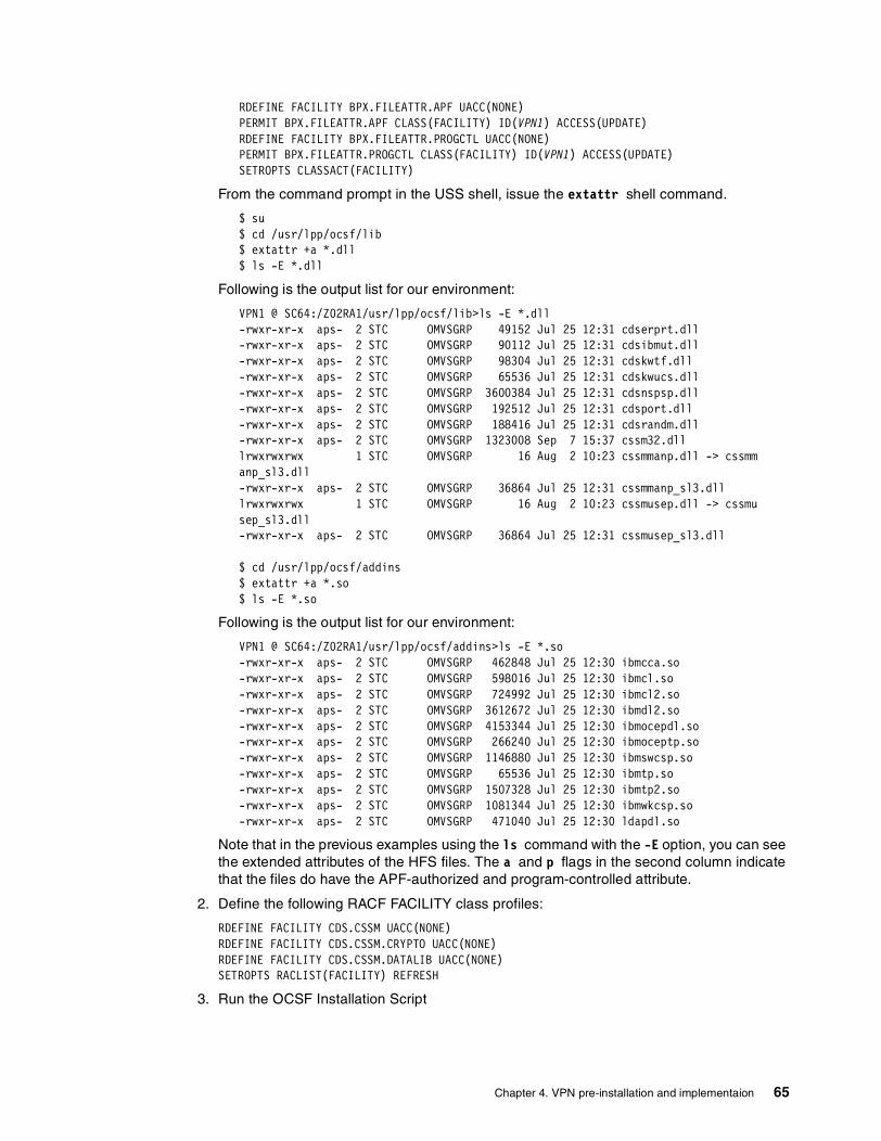
RDEFINE FACILITY BPX.FILEATTR.APF UACC(NONE)PERMIT BPX.FILEATTR.APF CLASS(FACILITY) ID(VPN1) ACCESS(UPDATE)RDEFINE FACILITY BPX.FILEATTR.PROGCTL UACC(NONE)PERMIT BPX.FILEATTR.PROGCTL CLASS(FACILITY) ID(VPN1) ACCESS(UPDATE)SETROPTS CLASSACT(FACILITY)
From the command prompt in the USS shell, issue the extattr shell command.
$ su$ cd /usr/lpp/ocsf/lib$ extattr +a *.dll$ ls -E *.dll
Following is the output list for our environment:
VPN1 @ SC64:/Z02RA1/usr/lpp/ocsf/lib>ls -E *.dll -rwxr-xr-x aps- 2 STC OMVSGRP 49152 Jul 25 12:31 cdserprt.dll-rwxr-xr-x aps- 2 STC OMVSGRP 90112 Jul 25 12:31 cdsibmut.dll-rwxr-xr-x aps- 2 STC OMVSGRP 98304 Jul 25 12:31 cdskwtf.dll -rwxr-xr-x aps- 2 STC OMVSGRP 65536 Jul 25 12:31 cdskwucs.dll-rwxr-xr-x aps- 2 STC OMVSGRP 3600384 Jul 25 12:31 cdsnspsp.dll-rwxr-xr-x aps- 2 STC OMVSGRP 192512 Jul 25 12:31 cdsport.dll-rwxr-xr-x aps- 2 STC OMVSGRP 188416 Jul 25 12:31 cdsrandm.dll-rwxr-xr-x aps- 2 STC OMVSGRP 1323008 Sep 7 15:37 cssm32.dlllrwxrwxrwx 1 STC OMVSGRP 16 Aug 2 10:23 cssmmanp.dll -> cssmmanp_sl3.dll-rwxr-xr-x aps- 2 STC OMVSGRP 36864 Jul 25 12:31 cssmmanp_sl3.dlllrwxrwxrwx 1 STC OMVSGRP 16 Aug 2 10:23 cssmusep.dll -> cssmusep_sl3.dll-rwxr-xr-x aps- 2 STC OMVSGRP 36864 Jul 25 12:31 cssmusep_sl3.dll
$ cd /usr/lpp/ocsf/addins$ extattr +a *.so $ ls -E *.so
Following is the output list for our environment:
VPN1 @ SC64:/Z02RA1/usr/lpp/ocsf/addins>ls -E *.so -rwxr-xr-x aps- 2 STC OMVSGRP 462848 Jul 25 12:30 ibmcca.so -rwxr-xr-x aps- 2 STC OMVSGRP 598016 Jul 25 12:30 ibmcl.so -rwxr-xr-x aps- 2 STC OMVSGRP 724992 Jul 25 12:30 ibmcl2.so -rwxr-xr-x aps- 2 STC OMVSGRP 3612672 Jul 25 12:30 ibmdl2.so -rwxr-xr-x aps- 2 STC OMVSGRP 4153344 Jul 25 12:30 ibmocepdl.so-rwxr-xr-x aps- 2 STC OMVSGRP 266240 Jul 25 12:30 ibmoceptp.so-rwxr-xr-x aps- 2 STC OMVSGRP 1146880 Jul 25 12:30 ibmswcsp.so -rwxr-xr-x aps- 2 STC OMVSGRP 65536 Jul 25 12:30 ibmtp.so -rwxr-xr-x aps- 2 STC OMVSGRP 1507328 Jul 25 12:30 ibmtp2.so -rwxr-xr-x aps- 2 STC OMVSGRP 1081344 Jul 25 12:30 ibmwkcsp.so -rwxr-xr-x aps- 2 STC OMVSGRP 471040 Jul 25 12:30 ldapdl.so
Note that in the previous examples using the ls command with the -E option, you can see the extended attributes of the HFS files. The a and p flags in the second column indicate that the files do have the APF-authorized and program-controlled attribute.
2. Define the following RACF FACILITY class profiles:
RDEFINE FACILITY CDS.CSSM UACC(NONE)RDEFINE FACILITY CDS.CSSM.CRYPTO UACC(NONE)RDEFINE FACILITY CDS.CSSM.DATALIB UACC(NONE)SETROPTS RACLIST(FACILITY) REFRESH
3. Run the OCSF Installation Script
Chapter 4. VPN pre-installation and implementaion 65
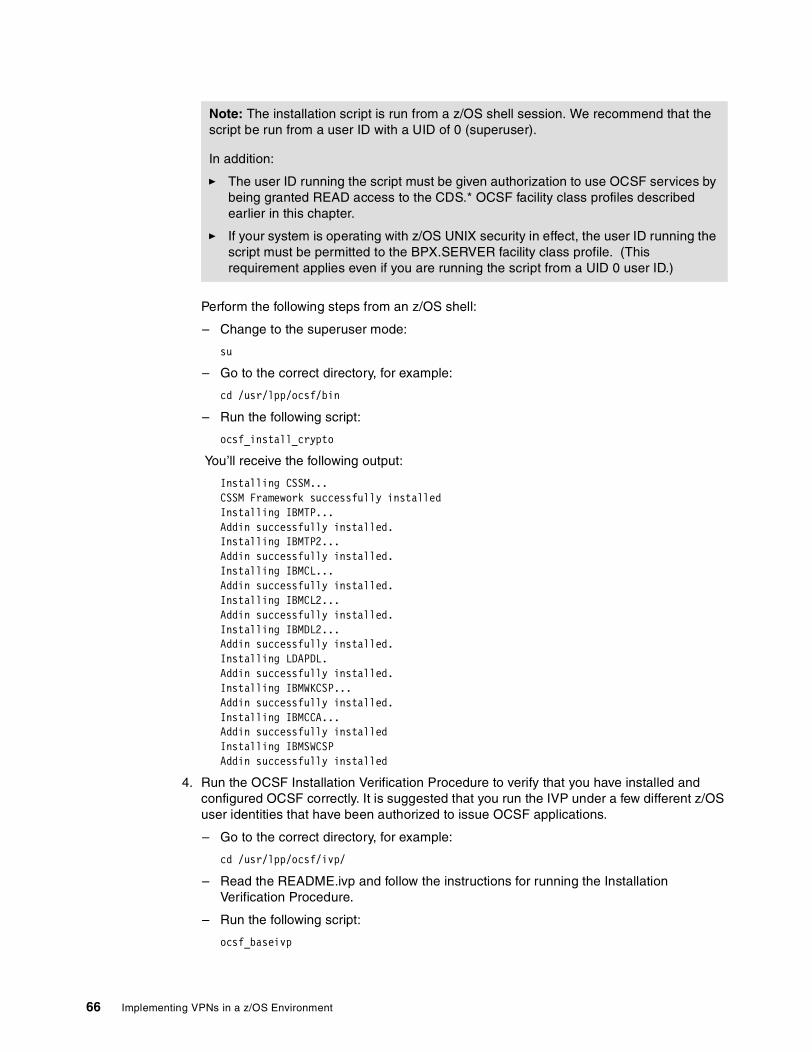
Perform the following steps from an z/OS shell:
– Change to the superuser mode:
su
– Go to the correct directory, for example:
cd /usr/lpp/ocsf/bin
– Run the following script:
ocsf_install_crypto
You’ll receive the following output:
Installing CSSM...CSSM Framework successfully installedInstalling IBMTP... Addin successfully installed.Installing IBMTP2...Addin successfully installed.Installing IBMCL...Addin successfully installed.Installing IBMCL2...Addin successfully installed.Installing IBMDL2...Addin successfully installed.Installing LDAPDL.Addin successfully installed.Installing IBMWKCSP...Addin successfully installed.Installing IBMCCA...Addin successfully installedInstalling IBMSWCSPAddin successfully installed
4. Run the OCSF Installation Verification Procedure to verify that you have installed and configured OCSF correctly. It is suggested that you run the IVP under a few different z/OS user identities that have been authorized to issue OCSF applications.
– Go to the correct directory, for example:
cd /usr/lpp/ocsf/ivp/
– Read the README.ivp and follow the instructions for running the Installation Verification Procedure.
– Run the following script:
ocsf_baseivp
Note: The installation script is run from a z/OS shell session. We recommend that the script be run from a user ID with a UID of 0 (superuser).
In addition:
� The user ID running the script must be given authorization to use OCSF services by being granted READ access to the CDS.* OCSF facility class profiles described earlier in this chapter.
� If your system is operating with z/OS UNIX security in effect, the user ID running the script must be permitted to the BPX.SERVER facility class profile. (This requirement applies even if you are running the script from a UID 0 user ID.)
66 Implementing VPNs in a z/OS Environment

You will receive the following output:
Starting OCSF base addins ivp Initializing CSSM CSSM Initialized Attaching ibmwkcsp Attach successful, detaching ibmwkcspDetach of ibmwkcsp successful Attaching ibmswcsp Attach successful, detaching ibmswcspDetach of ibmswcsp successful Attaching ibmcca Attach successful, detaching ibmcca Detach of ibmcca successful Attaching ibmcl Attach successful, detaching ibmcl Detach of ibmcl successful Attaching ibmcl2 Attach successful, detaching ibmcl2 Detach of ibmcl2 successful Attaching ibmdl2 Attach successful, detaching ibmdl2 Detach of ibmdl2 successful Attaching ldapdl Attach successful, detaching ldapdl Detach of ldapdl successful Attaching ibmtp Attach successful, detaching ibmtp Detach of ibmtp successful Attaching ibmtp2 Attach successful, detaching ibmtp2 Detach of ibmtp2 successful Completed OCSF base addins ivp
4.3 OCEP installation and configurationNow we will install the OCSF plug-ins. Ensure that the installation process enables the OCEP code for program control.
If you have not defined the following RACF facility class profiles, issue the following commands to define them:
RDEFINE FACILITY IRR.DIGTCERT.LIST UACC(NONE)RDEFINE FACILITY IRR.DIGTCERT.LISTRING UACC(NONE)SETROPTS RACLIST(FACILITY) REFRESH
Give the FWKERN user ID permission to use the class profiles:
PERMIT IRR.DIGTCERT.LIST CLASS(FACILITY) ID(FWKERN) ACC(READ)PERMIT IRR.DIGTCERT.LISTRING CLASS(FACILITY) ID(FWKERN) ACC(READ)SETROPTS RACLIST(FACILITY) REFRESH
Give permission to use the class profiles to the user ID that will install the code and run the IVP programs:
PERMIT IRR.DIGTCERT.LIST CLASS(FACILITY) ID(vpn1) ACC(READ)PERMIT IRR.DIGTCERT.LISTRING CLASS(FACILITY) ID(vpn1) ACC(READ)SETROPTS RACLIST(FACILITY) REFRESH
Chapter 4. VPN pre-installation and implementaion 67

Mark the OCSF-enhanced plug-in programs in the OCSF UNIX Library APF authorized and program-controlled:
$ su$ cd /usr/lpp/ocsf/addins$ extattr +ap *.so$ ls -E *.so
Run the installation script from a z/OS shell. To run this command, you must have superuser authority (UID=0).
$ cd /usr/lpp/ocsf/bin$ ocep_install
You will receive the following output:
Installing IBMOCEPTP...Addin successfully installed.Installing IBMOCEPDL...Addin successfully installed.
Now, run the Installation Verification Procedures (IVP). This verifies that you have installed and configured the product correctly.
$ cd /usr/lpp/ocsf/ivp$ ocep_ivp
You will receive the following output:
Starting OCEP IVPInitializing CSSMCSSM InitializedAttaching ibmocepdlAttach successful, Detaching ibmocepdlDetach of ibmocepdl successfulAttaching ibmoceptpAttach successful, Detaching ibmoceptpDetach of ibmoceptp successfulCompleted OCEP IVP
4.4 Configuring and using the ISAKMP serverThe ISAKMP server (or daemon) negotiates dynamic security associations (SAs) with other servers or hosts which support the ISAKMP/Oakley standards developed by the IETF. The ISAKMP server can negotiate an ISAKMP (Phase 1) SA that will be used to protect the negotiation of IPSec (Phase 2) SAs.
These IPSec SAs can then be used to protect user data, allowing secure communication through nonsecure networks.
Configuring and starting the ISAKMP DaemonTo enable the IKE function, we need to configure (in the /etc/services file) and start up the ISAKMPD daemon. The ISAKMP server is listening on UDP port 500 to communicate with other servers or hosts. Also you need to verify that the right filter rules are established to allow this communication to occur. Predefined services 52 and 53 (ISAKMPD UDP Non-Secure and ISAKMPD UDP Secure) can be used to enable this communication. The server listens only to active firewall stacks. The server will connect or reconnect to stacks that are started or restarted later.
68 Implementing VPNs in a z/OS Environment

To instruct the firewall kernel (FWKERN) to automatically start the ISAKMP daemon, issue the following command:
fwdaemon cmd=change daemon=isakmpd started=yes daemonopts=-l
In order for the ISAKMP server to operate correctly, the fwstackd daemon must also be started. This server should already be configured to be started. If fwstackd is not started, then issue the following command to start it:
fwdaemon cmd=change daemon=fwstackd started=yes
The ISAKMP server supports several options, which can be specified on the daemonopts parameter of the fwdaemon command. You can add the following options to the ISAKMPD entry in the configuration file:
[-keyretry nnnn][-keywait nnnn][-dataretry nnnn][-datawait nnnn][-L]
-keyretry nnnnSpecifies the number of times that an unanswered key negotiation (Phase 1) message will be retransmitted before the negotiation is aborted. nnnn can be 0-9999. The default is 10 retransmissions.
-keywait nnnnSpecifies the number of seconds between retransmissions of key negotiation (Phase 1) messages. nnnn can be 0-9999. The default is 30 seconds.
-dataretry nnnnSpecifies the number of times that an unanswered data negotiation (Phase 2) message will be retransmitted before the negotiation is aborted. nnnn can be 0-9999. The default is 10 retransmissions.
-datawait nnnnSpecifies the number of seconds between retransmissions of data negotiation (Phase 2) messages. nnnn can be 0-9999. The default is 15 seconds.
-LEchoes all ISAKMPD log messages to the job output file, normally named IKEDOUT.
ExampleTo specify that key negotiation messages should be retransmitted 5 times, at 20 second intervals, issue the following command:
fwdaemon cmd=change daemon=isakmpd daemonopts="-keyretry 5 -keywait 20"
4.5 Setting up the configuration server and clientThis section describes how to set up the configuration server and client for the z/OS Firewall Technologies. The configuration client is a graphical user interface (GUI) that enables a user to connect to the configuration server and setup VPNs. Figure 4-2 on page 70 shows the network configuration we used for this scenario.
Chapter 4. VPN pre-installation and implementaion 69

Figure 4-2 Configuration client connectivity to our z/OS environment
Configuring SSLThe firewall configuration server uses the Secure Sockets Layer (SSL) protocol of z/OS for communication between the GUI clients and the server.
The administrator must create or acquire a certificate and place it in either a key database or the External Security Manager (ESM). To create a self-signed certificate, use either the gskkyman SSL command or the RACDCERT RACF command. To obtain a certificate from a recognized Certificate Authority, use either gskkyman or RACDCERT to create the request. In this case, both the obtained certificate and all CA certificates in the CA hierarchies that signed the obtained certificate must be put into the key database or ESM.
Note: If you are currently using a key database and choose to use an ESM keyring, use gskkyman to export the certificate(s) to a PKCS12 file. The keyring must be owned by the user ID that the FWKERN started task runs under. FWKERN does not have to be run under the FWKERN user ID.
Configuring the configuration server (CFGSRV)The configuration server must be configured to use the SSL option. Because the clients can only connect to the server using SSL, failure to configure the server with the SSL option will result in a connection failure between the client and the server.
1. The SSL library hlq.SGSKLOAD must be APF-authorized, and available to firewall through either a STEPLIB DD statement or through LNKLSTxx. To use STEPLIB, update the ICAPCFGS PROCLIB member with a //STEPLIB DD statement that references hlq.SGSKLOAD.
2. To configure with the SSL option use either of these daemonopts:
a. For certificates in a key database: the -f option with the fully-qualified name of the key database file (.kdb), or
b. For certificates stored in an ESM: the -k option with the name of the keyring.
SC64TS SC65TS
10.10.65.1 192.168.30.1
9.12.6.699.12.6.73
9.12.6.124
Configurationclient GUI
70 Implementing VPNs in a z/OS Environment

In either case, the certificate’s label may be specified with the -l option and the port may be specified with the -p option. When the certificate is the keyring’s default, the -l option need not be used. The default port is 1014. The -k and -f options are mutually exclusive.
fwdaemon cmd=change daemon=CFGSRV daemonopts="-f /etc/security/cfgsrv.kdb -p 1014"
3. Configure the server for starting by FWKERN:
fwdaemon cmd=change started=yes daemon=CFGSRV
FWKERN will now start the configuration server at startup. If FWKERN is already running, start the server using fwdaemon from OMVS or use the Modify command from the operator’s console:
fwdaemon cmd=start daemon=CFGSRV
orF FWKERN,START CFGSRV
Configuring filter rules for the configuration clientNow the firewall server has to be configured to support the configuration client connection. We have to define some filter rules to permit the connection to the secure interface. We have to create a filter rule to permit all connections through the secure interface or only permit some services, such as the configuration client service using port 1014. In our environment, we permit all types of traffic in the secure interface.
The following steps show how to customize a filter rule to permit all types of traffic to the secure interface on the SC64TS host. You have to go to the UNIX System Services shell environment using the authorized user ID defined previously and perform the following commands.
� Define the firewall filter rules:
>su
Note: You must have filter rules which allow TCP traffic to flow to the configuration server, such as in the following example:
fwfrule cmd=add name='#Permit All'",desc='permit all' type=permit",protocol=all interface=both routing=both direction=both"log=no"
Note: To start the configuration server in the Japanese code page (Ja_JP.IBM-939), using an HFS key database file, perform the following steps. (These steps are not necessary when using an ESM to manage the certificates.)
1. A Japanese-based SSL key database and self-signed certificate must be created by the gskkyman command. This is accomplished by setting the LANG environment variable to Ja_JP.IBM-939 prior to invoking the gskkyman command.
2. The LANG environment variable associated with the configuration server must be set to Ja_JP.IBM-939. This is accomplished by issuing the following command prior to starting the configuration server:
fwdaemon cmd=change daemon=cfgsrv runopts=’ENVAR("LANG=Ja_JP.IBM-939")’
Note: The same sequence of definitions, with some relevant changes, can be used on SC65TS host to allow the GUI client access to CFGSRV on that host.
Chapter 4. VPN pre-installation and implementaion 71

>fwfrule cmd=add name="#SC64TS Permit All Secure" \desc="Permit all in the Secure Interface" type=permit protocol=all \srcopcode=any srcport=0 destopcode=any destport=0 interface=secure \routing=local direction=both log=yes
>fwfrule cmd=list name="#SC64TS Permit All Secure"id = 506type = permitname = #SC64TS Permit All Securedesc = Permit all traffic in the secure interfaceprotocol = allsrcopcode = anysrcport = 0destopcode = anydestport = 0interface = securerouting = localdirection = bothlog = yestunnel =fragment =
� Create a firewall configuration client service that contains the rule created in the previous step:
>fwservice cmd=create name="#SC64TS Permit All Secure" \desc="Permit all in the secure interface" rulelist=506/f,506/b
� List the service you have created to get the ID. It will be used in the fwconns command.
>fwservice cmd=list name="#SC64TS Permit All Secure" id = 505name = #SC64TS Permit All Securedesc = Permit all in the secure interfacerulelist = 506/f,506/blog = fragment =tunnel =time =month =day =weekday =timefilter =
� Create a network object that represents your intranet:
>fwnwobj cmd=add name="#Network 9.0.0.0" \desc="IBM Intranet" type=network addr=9.0.0.0 mask=255.0.0.0
� Create a network object that represents the host where the firewall server is running:
>fwnwobj cmd=add name="#Host 9.12.6.69" \desc="Host 9.12.6.69" type=host addr=9.12.6.69 mask=255.255.255.255
� List the network object to get the ID. It will be used in the fwconns command.
Note: To use the firewall commands you have to be in superuser mode or a member of the FWGRP group. Using the su command, you can change to superuser mode.
The first fwfrule command above created a rule that allows any kind of traffic over the secure interface to the local host, the second command lists the rule that we have created in order to get the rule ID. This rule ID will be used in the next fwservice and fwconn commands.
72 Implementing VPNs in a z/OS Environment
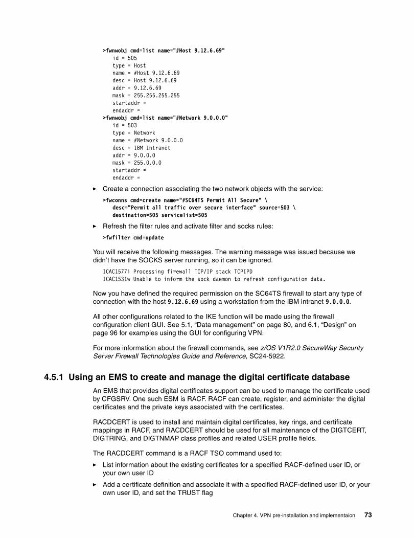
>fwnwobj cmd=list name="#Host 9.12.6.69"id = 505type = Hostname = #Host 9.12.6.69desc = Host 9.12.6.69addr = 9.12.6.69mask = 255.255.255.255startaddr =endaddr =
>fwnwobj cmd=list name="#Network 9.0.0.0"id = 503type = Networkname = #Network 9.0.0.0desc = IBM Intranetaddr = 9.0.0.0mask = 255.0.0.0startaddr =endaddr =
� Create a connection associating the two network objects with the service:
>fwconns cmd=create name="#SC64TS Permit All Secure" \desc="Permit all traffic over secure interface" source=503 \destination=505 servicelist=505
� Refresh the filter rules and activate filter and socks rules:
>fwfilter cmd=update
You will receive the following messages. The warning message was issued because we didn’t have the SOCKS server running, so it can be ignored.
ICAC1577i Processing firewall TCP/IP stack TCPIPDICAC1531w Unable to inform the sock daemon to refresh configuration data.
Now you have defined the required permission on the SC64TS firewall to start any type of connection with the host 9.12.6.69 using a workstation from the IBM intranet 9.0.0.0.
All other configurations related to the IKE function will be made using the firewall configuration client GUI. See 5.1, “Data management” on page 80, and 6.1, “Design” on page 96 for examples using the GUI for configuring VPN.
For more information about the firewall commands, see z/OS V1R2.0 SecureWay Security Server Firewall Technologies Guide and Reference, SC24-5922.
4.5.1 Using an EMS to create and manage the digital certificate databaseAn EMS that provides digital certificates support can be used to manage the certificate used by CFGSRV. One such ESM is RACF. RACF can create, register, and administer the digital certificates and the private keys associated with the certificates.
RACDCERT is used to install and maintain digital certificates, key rings, and certificate mappings in RACF, and RACDCERT should be used for all maintenance of the DIGTCERT, DIGTRING, and DIGTNMAP class profiles and related USER profile fields.
The RACDCERT command is a RACF TSO command used to:
� List information about the existing certificates for a specified RACF-defined user ID, or your own user ID
� Add a certificate definition and associate it with a specified RACF-defined user ID, or your own user ID, and set the TRUST flag
Chapter 4. VPN pre-installation and implementaion 73

� Alter the TRUST flag or the LABEL name for an existing definition
� Delete a definition
� List a certificate contained in a data set and determine if it is associated with a RACF-defined user ID
� Add or remove a certificate from a key ring
� Create, delete, or list a key ring
� Generate a public/private key pair and certificate
� Write a certificate to a data set
� Create a certificate request
� Create, alter, delete, or list a user ID mapping
Additional keywords on the RACDCERT command allow some information about the certificate or key ring to be listed, the label and status flag to be altered, and the certificate or key ring to be deleted.
To facilitate the altering and deleting of a certificate definition, you need to enter the minimum amount of information needed to uniquely identify the definition to be changed. If only one certificate is defined for the user ID, then only the ID is required. If more than one certificate is defined to the user ID, the LABEL or SERIALNUMBER is also required. If the SERIALNUMBER is not unique for the user ID, the ISSUERSDN is also required.
Authorization required To issue the RACDCERT command, you must have one of the following authorities:
� SPECIAL
� Sufficient authority to resource IRR.DIGTCERT.function in the FACILITY class
Users with SPECIAL authority can generate a digital certificate for any RACF-defined user or for any certificate authority or site certificate. Users without SPECIAL authority can generate certificate authority or site certificates if they have CONTROL authority to the resource IRR.DIGTCERT.ADD in the FACILITY class. Users without SPECIAL authority can generate certificates for other users if they have UPDATE authority to the resource IRR.DIGTCERT.ADD in the FACILITY class. Users without SPECIAL authority can generate certificates for themselves if they have READ authority to the resource IRR.DIGTCERT.ADD in the FACILITY class.
We used the following commands to generate the self-signed digital certificate on SC64TS firewall host for the CFGSRV:
RACDCERT ID(FWKERN) ADDRING(CFGSRV64RING)RACDCERT ID(FWKERN) GENCERT SUBJECTSDN(CN('SC64CFGSRV') O('IBM') +OU('ITSO') C('USA')) WITHLABEL('SC64CFGSRV') SIZE(1024) +KEYUSAGE(HANDSHAKE)RACDCERT ID(FWKERN) CONNECT(ID(FWKERN) LABEL('SC64CFGSRV') +RING(CFGSRV64RING) USAGE(PERSONAL) DEFAULT)
4.5.2 Using GSKKYMAN to create and manage the digital certificate databaseAlternatively, you can use the system SSL tool GSKKYMAN to generate the digital certificate for SSL CFGSRV usage. The screens shown in the next three figures demonstrate how we to run the GSKKYMAN utility to create a new key database (if one was not already created), and use the “Create a self-signed certificate” option to create and store a self-signed certificate, then use the “Store encrypted database password” option.
74 Implementing VPNs in a z/OS Environment

GSKKYMAN uses the DLLs that are installed with System SSL and must have access to these at run time. GSKKYMAN must also have access to the message catalogs. /bin includes a symbolic link to /usr/lpp/gskssl/bin/gskkyman. Therefore, if your PATH environment variable contains this directory, you will find the GSKKYMAN utility. If your PATH environment variable does not contain this directory, add /usr/lpp/gskssl/bin to your PATH using the following:
PATH=$PATH:/usr/lpp/gskssl/bin
The directories /usr/lib/nls/msg/C and /usr/lib/nls/msg/En_US.IBM-1047 (and /usr/lib/nls/msg/Ja_JP for JCPT272 installations) include symbolic links to the message catalogs for GSKKYMAN. If they do not include these links, add /usr/lpp/gskssl/lib/nls/msg to your NLSPATH using the following command:
export NLSPATH=$NLSPATH:/usr/lpp/gskssl/lib/nls/msg/%L/%N
This setting assumes that your environment has the LANG environment variable set to En_US.IBM-1047 (Ja_JP for JCPT272 installations that expect Japanese messages and prompts). If LANG is not set properly, set the NLSPATH environment variable using the following command:
export NLSPATH=$NLSPATH:/usr/lpp/gskssl/lib/nls/msg/En_US.IBM-1047/%N
Or for JCPT272 installations that expect Japanese messages and prompts:
export NLSPATH=$NLSPATH:/usr/lpp/gskssl/lib/nls/msg/Ja_JP/%N
The DLLs for System SSL are installed in a partitioned data set (PDS). These DLLs are not installed in the LINKLIB or LPALIB by default. To access these DLLs, if they have not been placed in LINKLIB or LPALIB, you must set the STEPLIB environment variable to find the DLLs. Consult your system programmer for the high-level qualifier of the System SSL PDS. In the following example, the high-level qualifier for the System SSL PDS is GSK. In the following command, replace the value to meet your installation:
export STEPLIB=GSK.SGSKLOAD
Figure 4-3 GSKKYMAN utility: Main menu
VPN1 @ SC64:/>gskkyman
IBM Key Management Utility
Choose one of the following options to proceed.
1 - Create new key database2 - Open key database3 - Change database password
0 - Exit program
Enter your option number: 1Enter key database name or press ENTER for"key.kdb": cfgsrv.kdbEnter password for the key database.......>Enter password again for verification.....>Should the password expire? (1 = yes, 0 = no)
The database has been successfully created, do youwant to continue to work withthe database now? (1 = yes, 0 = no)===> 1
Chapter 4. VPN pre-installation and implementaion 75
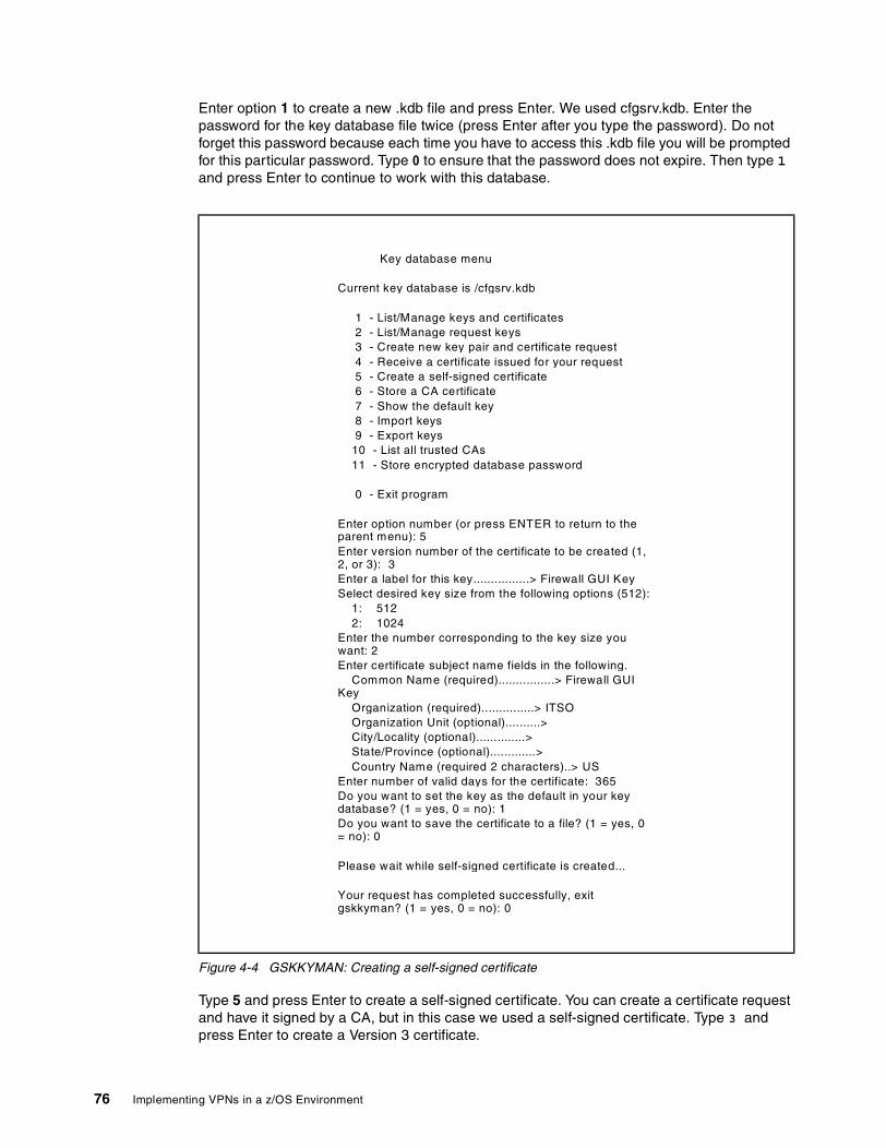
Enter option 1 to create a new .kdb file and press Enter. We used cfgsrv.kdb. Enter the password for the key database file twice (press Enter after you type the password). Do not forget this password because each time you have to access this .kdb file you will be prompted for this particular password. Type 0 to ensure that the password does not expire. Then type 1and press Enter to continue to work with this database.
Figure 4-4 GSKKYMAN: Creating a self-signed certificate
Type 5 and press Enter to create a self-signed certificate. You can create a certificate request and have it signed by a CA, but in this case we used a self-signed certificate. Type 3 and press Enter to create a Version 3 certificate.
Key database menu
Current key database is /cfgsrv.kdb
1 - List/Manage keys and certificates2 - List/Manage request keys3 - Create new key pair and certificate request4 - Receive a certificate issued for your request5 - Create a self-signed certificate6 - Store a CA certificate7 - Show the default key8 - Import keys9 - Export keys
10 - List all trusted CAs11 - Store encrypted database password
0 - Exit program
Enter option number (or press ENTER to return to theparent menu): 5Enter version number of the certificate to be created (1,2, or 3): 3Enter a label for this key................> Firewall GUI KeySelect desired key size from the following options (512):
1: 5122: 1024
Enter the number corresponding to the key size youwant: 2Enter certificate subject name fields in the following.
Common Name (required)................> Firewall GUIKey
Organization (required)...............> ITSOOrganization Unit (optional)..........>City/Locality (optional)..............>State/Province (optional).............>Country Name (required 2 characters)..> US
Enter number of valid days for the certificate: 365Do you want to set the key as the default in your keydatabase? (1 = yes, 0 = no): 1Do you want to save the certificate to a file? (1 = yes, 0= no): 0
Please wait while self-signed certificate is created...
Your request has completed successfully, exitgskkyman? (1 = yes, 0 = no): 0
76 Implementing VPNs in a z/OS Environment

The version number refers to the X.509 standard version number. Type a label for the key and press Enter. Type a common name and press Enter. Type an organization name and press Enter. All the other fields are optional. Then type the number of days this certificate should be valid and press Enter. We chose one year. Type 1 and press Enter to set this key as the default key in this database. Type 0 and press Enter to not save this certificate into a file. Type 0 and press Enter to return to the previous menu.
Figure 4-5 GSKKYMAN: Storing an encrypted password
Type 11 and press Enter to store the encrypted database password in a stashed file. Finally, type 1 and press Enter to leave GSKKYMAN.
By this time you should have three files in the directory in which you were running GSKKYMAN: a key database file, a request database file and a stash file whose file names in our example were cfgsrv.kdb, cfgsrv.rdb and cfgsrv.sth, respectively. The .kdb file contains the keys and certificates you created and the .sth file contains the database password.
Copy these files to the directory you specified in the fwdaemon daemonopts parameter for the CFGSRV server. In our setup it was /etc/security/.
4.5.3 Setting up the configuration client on Windows
System requirementsTo set up the configuration GUI on a Windows machine, you will need:
� Windows 95/98/Millenium Edition, Windows NT 4.0, or Windows 2000.
� Zip tool that handles long file names such as the WinZip32 tool in WinZip. Information about WinZip can be found at:
http://www.winzip.com
Key database menu
Current key database is /cfgsrv.kdb
1 - List/Manage keys and certificates2 - List/Manage request keys3 - Create new key pair and certificate request4 - Receive a certificate issued for your request5 - Create a self-signed certificate6 - Store a CA certificate7 - Show the default key8 - Import keys9 - Export keys10 - List all trusted CAs11 - Store encrypted database password
0 - Exit program
Enter option number (or press ENTER to return to theparent menu): 11
The encrypted password has been stored in file/cfgsrv.sth
Your request has completed successfully, exitgskkyman? (1 = yes, 0 = no): 1VPN1 @ SC64:/>
Chapter 4. VPN pre-installation and implementaion 77
z/OS InstallationDuring the installation of z/OS Firewall Technologies, the Windows configuration GUI code is located in the /usr/lpp/fw/bin/fwtech.zip. Download this file to the Windows machine using FTP or a similar facility. If FTP is used to transmit the file, the BINary option must be set before the GET or PUT is issued. Also, if the firewall is already active on z/OS, you must have filter rules to allow the FTP connection between the firewall and the client.
1. When the fwtech.zip file resides on the client, it must be unzipped using the WINZIP tool or a similar facility.
2. Once decompressed, the client is installed using the setup.exe included in the zip file. This will begin a standard InstallShield installation process.
3. The first installation option is the desired locale. The supported locales are en_US (US English) and ja_JP (Japanese PC). Select the desired locale.
4. The next installation option is the desired installation directory. This is where the configuration client will be placed.
5. Proceed according to the remaining InstallShield instructions to complete the installation process.
6. Once installed, a program folder z/OS Firewall Technologies Client will be created along with a shortcut icon Configuration Client to the final installation directory. Double-click on this icon to start the configuration client.
7. The configuration client shortcut can be customized. The default logon timeout—the maximum time the client will spend attempting to connect to the configuration server—is 45 seconds. This can be changed by modifying the tl= parameter in the properties page of the icon.
Refer to Chapter 5, “Data management and key management configuration” on page 79 or Chapter 6, “Configuring z/OS Dynamic tunnels - branch office example” on page 95 for examples using the GUI to configure VPN tunnels.
78 Implementing VPNs in a z/OS Environment

Chapter 5. Data management and key management configuration
This chapter provides detailed steps for defining data management and key management attributes based on the samples “z/OS Tunnel - ESP auth & encrypt - Gold” and “z/OS Main Mode - Preshared Key - Gold,” respectively. You can follow the same procedures to create any other policies you require based on other preconfigured samples. The configuration client must be installed in order to follow this example (see “Setting up the configuration server and client” on page 69).
The configuration client distinguishes between sample objects that come preconfigured in z/OS Firewall Technologies from locally defined objects, by the color, or by the icon to the left of the object name: red for preconfigured objects, blue for locally defined objects. In our examples we also precede our object names with a pound sign (#) to help differentiate and to have them sort to the top of each list.
As opposed to referencing any of the sample objects directly, we make our own copies of them for a number of reasons:
� We can change any of the attributes of locally defined objects. The sample objects cannot be changed.
� By using our methodology of preceding the name with the special character #, all of the objects we need to reference will always be at the top of the list window.
� We know at a glance how many different policies we are using because they are at the top of the list window and contain the special character.
5
© Copyright IBM Corp. 2002 79
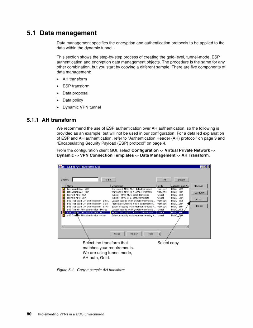
5.1 Data managementData management specifies the encryption and authentication protocols to be applied to the data within the dynamic tunnel.
This section shows the step-by-step process of creating the gold-level, tunnel-mode, ESP authentication and encryption data management objects. The procedure is the same for any other combination, but you start by copying a different sample. There are five components of data management:
� AH transform
� ESP transform
� Data proposal
� Data policy
� Dynamic VPN tunnel
5.1.1 AH transformWe recommend the use of ESP authentication over AH authentication, so the following is provided as an example, but will not be used in our configuration. For a detailed explanation of ESP and AH authentication, refer to “Authentication Header (AH) protocol” on page 3 and “Encapsulating Security Payload (ESP) protocol” on page 4.
From the configuration client GUI, select Configuration -> Virtual Private Network -> Dynamic -> VPN Connection Templates -> Data Management -> AH Transform.
Figure 5-1 Copy a sample AH transform
Select copy.Select the transform that matches your requirements. We are using tunnel mode, AH auth, Gold.
80 Implementing VPNs in a z/OS Environment

Figure 5-2 Save the new AH transform
You will be returned to the AH Transform list, which will include the newly created transform. Select Close.
5.1.2 ESP transformWe will use ESP authentication and encryption.
From the configuration client GUI, select Configuration -> Virtual Private Network -> Dynamic -> VPN Connection Templates -> Data Management -> ESP Transform.
Figure 5-3 Copy a sample ESP transform
Give your transform a name.
Save the new transform.
Select the transform that matches your requirements. We are using tunnel mode, ESP auth and encrypt, Gold.
Select copy.
Chapter 5. Data management and key management configuration 81
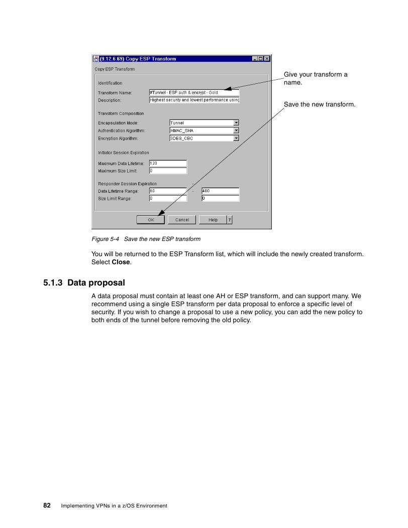
Figure 5-4 Save the new ESP transform
You will be returned to the ESP Transform list, which will include the newly created transform. Select Close.
5.1.3 Data proposalA data proposal must contain at least one AH or ESP transform, and can support many. We recommend using a single ESP transform per data proposal to enforce a specific level of security. If you wish to change a proposal to use a new policy, you can add the new policy to both ends of the tunnel before removing the old policy.
Give your transform a name.
Save the new transform.
82 Implementing VPNs in a z/OS Environment
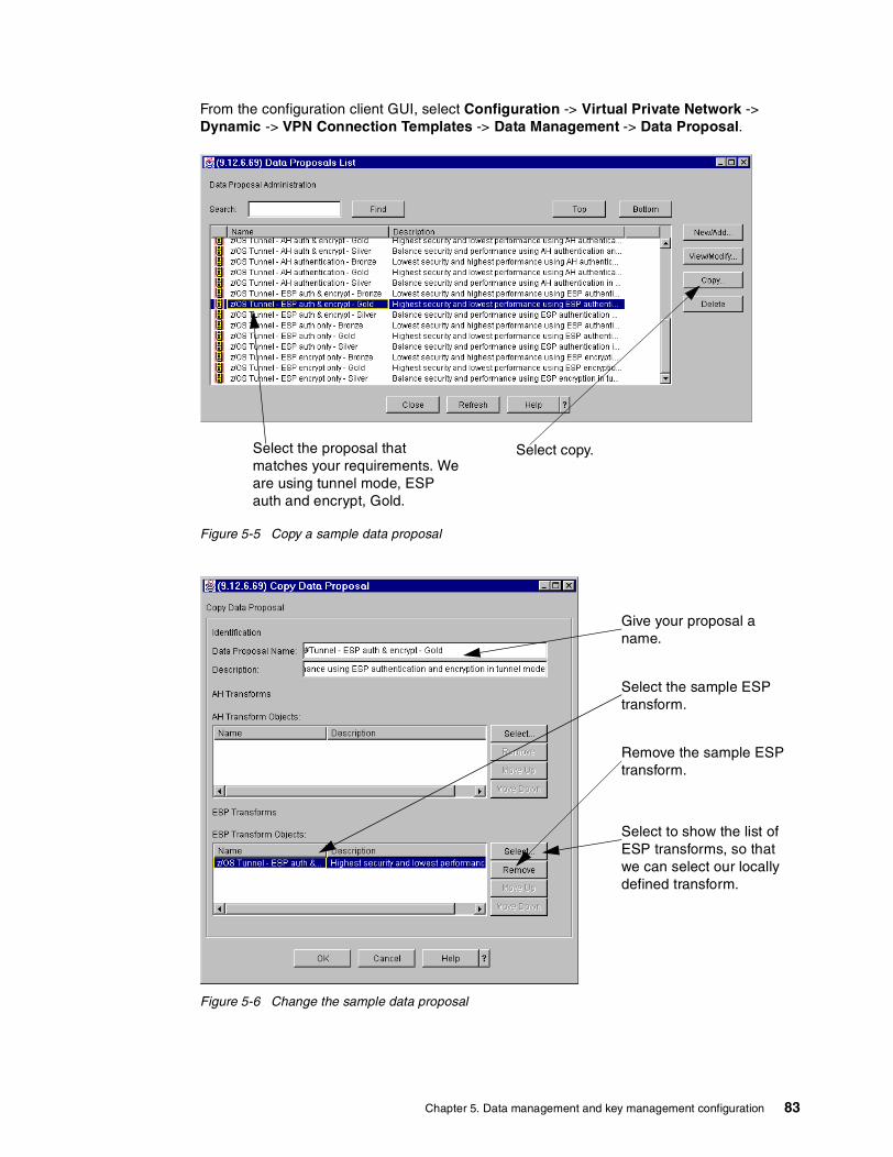
From the configuration client GUI, select Configuration -> Virtual Private Network -> Dynamic -> VPN Connection Templates -> Data Management -> Data Proposal.
Figure 5-5 Copy a sample data proposal
Figure 5-6 Change the sample data proposal
Select copy.Select the proposal that matches your requirements. We are using tunnel mode, ESP auth and encrypt, Gold.
Give your proposal a name.
Select the sample ESP transform.
Remove the sample ESP transform.
Select to show the list of ESP transforms, so that we can select our locally defined transform.
Chapter 5. Data management and key management configuration 83

Figure 5-7 Add a locally defined ESP transform
Figure 5-8 Save the new data proposal
You will be returned to the Data Proposal list, which will include the newly created proposal. Select Close.
Select the ESP transform that matches your requirements. We are using tunnel mode, ESP auth and encrypt, Gold.
Select OK.
Save the new proposal.
84 Implementing VPNs in a z/OS Environment
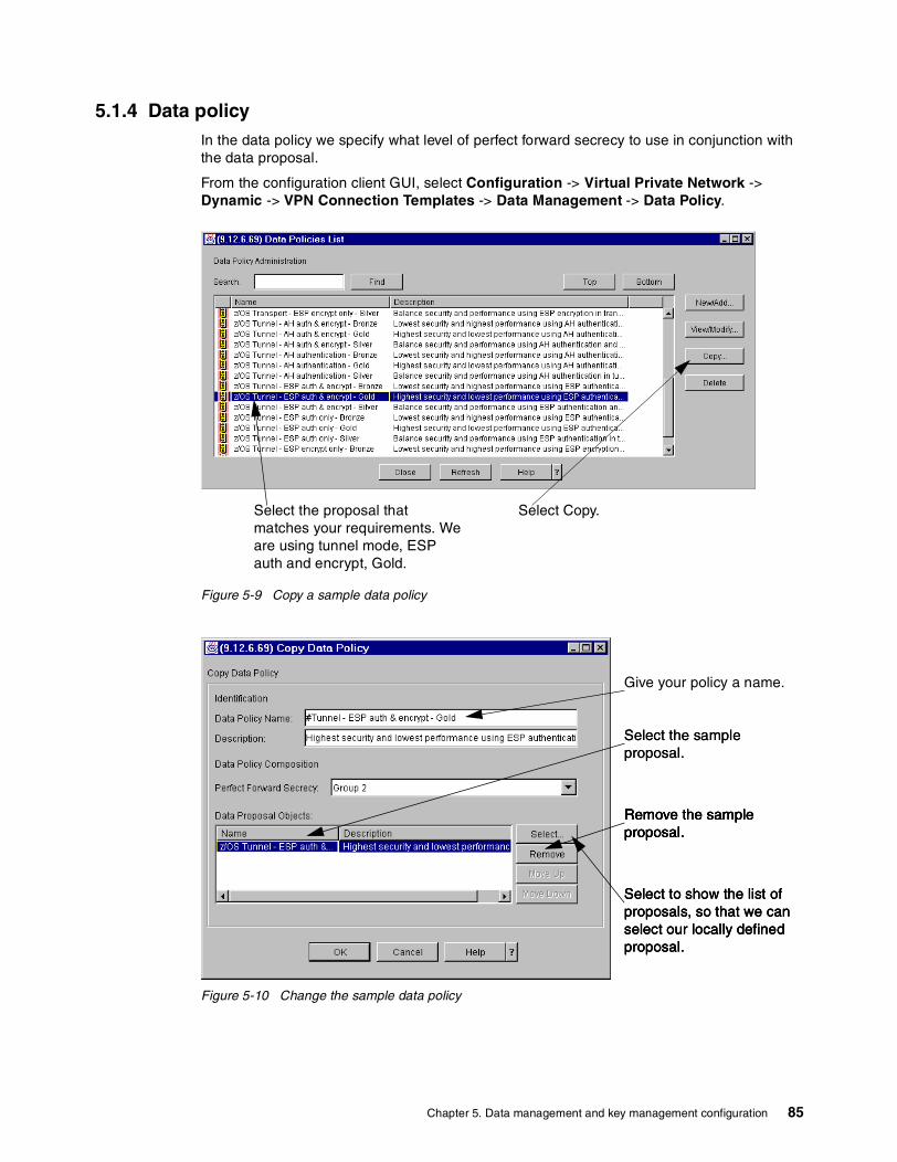
5.1.4 Data policyIn the data policy we specify what level of perfect forward secrecy to use in conjunction with the data proposal.
From the configuration client GUI, select Configuration -> Virtual Private Network -> Dynamic -> VPN Connection Templates -> Data Management -> Data Policy.
Figure 5-9 Copy a sample data policy
Figure 5-10 Change the sample data policy
Select Copy.Select the proposal that matches your requirements. We are using tunnel mode, ESP auth and encrypt, Gold.
Give your policy a name.
Select the sample proposal.
Remove the sample proposal.
Select to show the list of proposals, so that we can select our locally defined proposal.
Remove the sample proposal.
Select to show the list of proposals, so that we can select our locally defined proposal.
Select to show the list of proposals, so that we can select our locally defined proposal.
Remove the sample proposal.
Select the sample proposal.
Remove the sample proposal.
Chapter 5. Data management and key management configuration 85

Figure 5-11 Add a locally defined data proposal
Figure 5-12 Save the new data policy
You will be returned to the Data Policy list, which will include the newly created policy. Select Close.
Select the policy that matches your requirements. We are using tunnel mode, ESP auth and encrypt, Gold.
Select OK.
Save the new proposal.
86 Implementing VPNs in a z/OS Environment
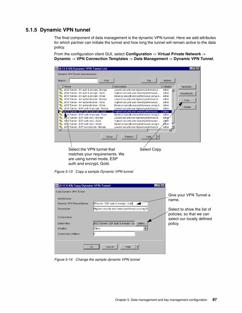
5.1.5 Dynamic VPN tunnelThe final component of data management is the dynamic VPN tunnel. Here we add attributes for which partner can initiate the tunnel and how long the tunnel will remain active to the data policy.
From the configuration client GUI, select Configuration -> Virtual Private Network -> Dynamic -> VPN Connection Templates -> Data Management -> Dynamic VPN Tunnel.
Figure 5-13 Copy a sample Dynamic VPN tunnel
Figure 5-14 Change the sample dynamic VPN tunnel
Select the VPN tunnel that matches your requirements. We are using tunnel mode, ESP auth and encrypt, Gold.
Select Copy.
Give your VPN Tunnel a name.
Select to show the list of policies, so that we can select our locally defined policy.
Chapter 5. Data management and key management configuration 87

Figure 5-15 Add a locally defined data policy
Figure 5-16 Save the new dynamic VPN tunnel
You will be returned to the Dynamic VPN Tunnel list, which will include the newly created VPN Tunnel. Select Close.
5.2 Key managementKey management specifies the encryption and authentication protocols to be applied to the key exchanges for the dynamic tunnel. There are three components of key management:
Select the policy that matches your requirements. We are using tunnel mode, ESP auth and encrypt, Gold.
Select OK.
Either end-point can initiate the tunnel.
Tunnel will stay up indefinitely.
Save the new VPN Tunnel.
88 Implementing VPNs in a z/OS Environment
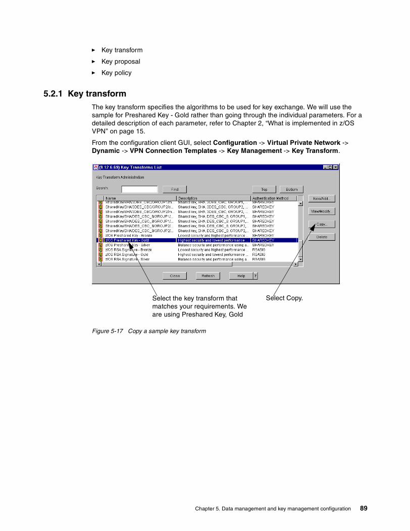
� Key transform
� Key proposal
� Key policy
5.2.1 Key transformThe key transform specifies the algorithms to be used for key exchange. We will use the sample for Preshared Key - Gold rather than going through the individual parameters. For a detailed description of each parameter, refer to Chapter 2, “What is implemented in z/OS VPN” on page 15.
From the configuration client GUI, select Configuration -> Virtual Private Network -> Dynamic -> VPN Connection Templates -> Key Management -> Key Transform.
Figure 5-17 Copy a sample key transform
Select the key transform that matches your requirements. We are using Preshared Key, Gold
Select Copy.
Chapter 5. Data management and key management configuration 89

Figure 5-18 Save the new key transform
You will be returned to the Key Transform list, which will include the newly created key transform. Select Close.
5.2.2 Key proposalSimilar to the data proposal, the key proposal allows you to support multiple key transforms. We recommend using a single transform per proposal to ensure that a specific set of algorithms are always used.
Give your transform a name.
Save the new transform.
90 Implementing VPNs in a z/OS Environment
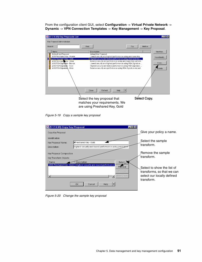
From the configuration client GUI, select Configuration -> Virtual Private Network -> Dynamic -> VPN Connection Templates -> Key Management -> Key Proposal.
Figure 5-19 Copy a sample key proposal
Figure 5-20 Change the sample key proposal
Select the key proposal that matches your requirements. We are using Preshared Key, Gold
Select Copy.Select Copy.
Give your policy a name.
Select the sample transform.
Remove the sample transform.
Select to show the list of transforms, so that we can select our locally defined transform.
Chapter 5. Data management and key management configuration 91

Figure 5-21 Add a locally defined key transform
Figure 5-22 Save the new key proposal
You will be returned to the Key Proposal list, which will include the newly created key proposal. Select Close.
5.2.3 Key policyThe key policy will add the initiator and responder negotiation to the key proposal. We will use Main mode for both since it is a stronger algorithm (see Chapter 2, “What is implemented in z/OS VPN” on page 15 for a detailed description).
Select the transform that matches your requirements. We are using Preshared Key, Gold.
Select OK.Select the transform that matches your requirements. We are using Preshared Key, Gold.
Save the new proposal.
92 Implementing VPNs in a z/OS Environment
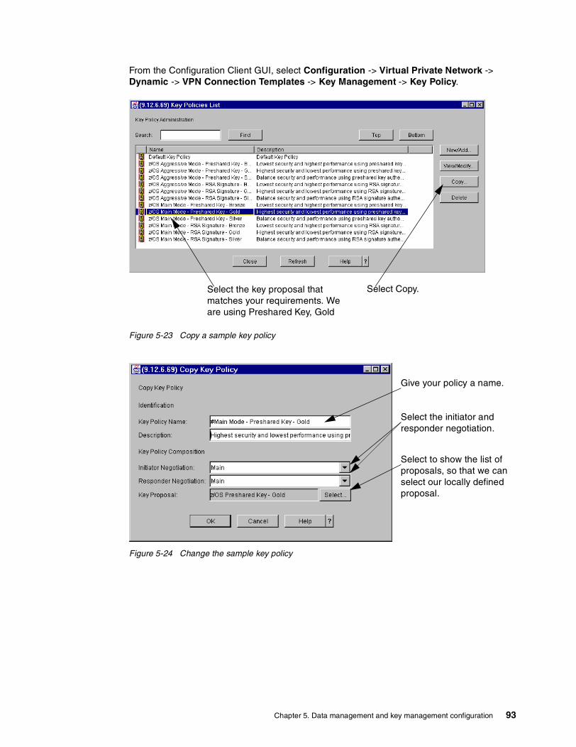
From the Configuration Client GUI, select Configuration -> Virtual Private Network -> Dynamic -> VPN Connection Templates -> Key Management -> Key Policy.
Figure 5-23 Copy a sample key policy
Figure 5-24 Change the sample key policy
Select the key proposal that matches your requirements. We are using Preshared Key, Gold
Select Copy.
Give your policy a name.
Select to show the list of proposals, so that we can select our locally defined proposal.
Select the initiator and responder negotiation.
Chapter 5. Data management and key management configuration 93
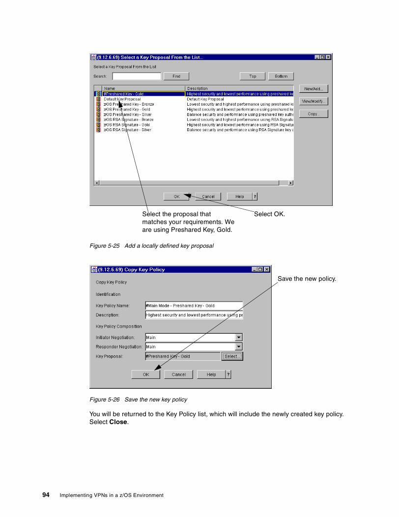
Figure 5-25 Add a locally defined key proposal
Figure 5-26 Save the new key policy
You will be returned to the Key Policy list, which will include the newly created key policy. Select Close.
Select OK.Select the proposal that matches your requirements. We are using Preshared Key, Gold.
Save the new policy.
94 Implementing VPNs in a z/OS Environment

Chapter 6. Configuring z/OS Dynamic tunnels - branch office example
This chapter, through the use of a branch office example, provides detailed configuration steps for defining dynamic tunnels. z/OS Firewall Technologies uses industry-standard protocols and can interoperate with products from other vendors; however, we will focus specifically on the z/OS perspective.
The configuration client (GUI) distinguishes between sample objects that come preconfigured in z/OS Firewall Technologies from locally defined objects, by the color, or by the icon to the left of the object name: red for preconfigured objects, blue for locally defined objects. In our examples, we also precede our object names with a number sign (#) to help differentiate them and to have them sort to the top of each list.
6
© Copyright IBM Corp. 2002 95

6.1 DesignOur branch office scenario will connect two networks (headquarters and branch office) over the Internet using a VPN; see Figure 6-1:
Figure 6-1 Branch office configuration
Note the following:
� The headquarters network is 9.12.6.0 with a subnet mask of 255.255.255.0� The branch office network is 9.12.8.0 with a subnet mask of 255.255.255.0
Each network has a z/OS server with IP forwarding enabled between it and the public network; these are labelled SC65 and SC64 in Figure 6-1. We will configure a VPN tunnel between the z/OS servers for all traffic between the two networks. Since the tunnel endpoints, SC65 and SC64, are not the same as the data endpoints, tunnel mode must be used (refer to “Tunnel endpoints same as data endpoints?” on page 40).
SC65 has a secure interface connected to the private headquarters network (9.12.6.1) and a non-secure interface connected to the public network (10.10.65.1). We are only simulating a public network in our lab environment, so 10.10.65.1 can be used. If this were a real public network, a publicly routable IP address would be required for this interface.
SC64 has a secure interface connected to the private branch network (9.12.8.1) and a non-secure interface connected to the public network (192.168.30.1). We are only simulating a public network in our lab environment, so 192.168.30.1 can be used. If this were a real public network, a publicly routable IP address would be required for this interface.
Because SC65 and SC64 are connected to each other via their non-secure interfaces, 10.10.65.1 and 192.168.30.1 will be used as the gateway IP addresses in the VPN configuration.
We will use Tunnel mode gold level ESP authentication and encryption for data management, and gold level main mode with preshared key for key management.
6.2 Key Server setupThe Key Server configuration dictates how the peers will identify themselves to one another and which key management policy they will use.
AIXClient
z/OSGATEWAY
z/OSGATEWAY
SC65 SC64
10.10.65.1 192.168.30.1
.2
HeadquartersNetwork9.12.6
.1
.130
WindowsClient
Branch OfficeNetwork9.12.8
INTERNET
Fast EthernetLAN.1
ESP Tunnel encryption & authentication
Fast EthernetLAN
96 Implementing VPNs in a z/OS Environment

There are two components of Key Server setup:
� Key Servers� Key Server Group
6.2.1 Key ServersThe tunnel endpoints are the Key Servers. In our branch office example they will be using IPV4 authentication. Both Key Servers must be defined on both sides of the connection.
First we add the branch office Key Server; from the Configuration Client GUI, select Configuration -> Virtual Private Network -> Dynamic -> Key Servers -> Key Server -> New/Add.
Figure 6-2 Add the branch office Key Server
Next we add the headquarters Key Server; from the Configuration Client GUI, select Configuration -> Virtual Private Network -> Dynamic -> Key Servers -> Key Server -> New/Add.
Give your key server a name.
Specify the IP address or the host name.
Select the type of auth ID.
Save the key server.
Specify the auth ID value.
Chapter 6. Configuring z/OS Dynamic tunnels - branch office example 97
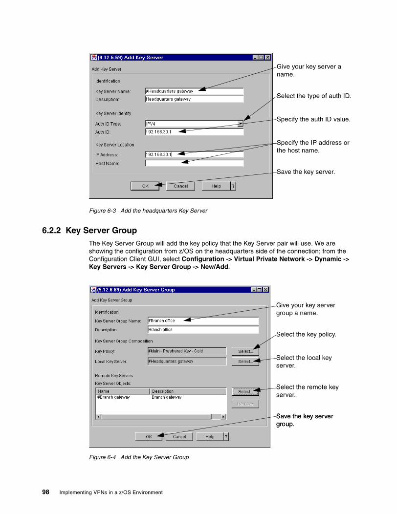
Figure 6-3 Add the headquarters Key Server
6.2.2 Key Server GroupThe Key Server Group will add the key policy that the Key Server pair will use. We are showing the configuration from z/OS on the headquarters side of the connection; from the Configuration Client GUI, select Configuration -> Virtual Private Network -> Dynamic -> Key Servers -> Key Server Group -> New/Add.
Figure 6-4 Add the Key Server Group
Give your key server a name.
Specify the IP address or the host name.
Select the type of auth ID.
Save the key server.
Specify the auth ID value.
Give your key server group a name.
Select the local key server.
Select the key policy.
Select the remote key server.
Save the key server group.Save the key server group.
98 Implementing VPNs in a z/OS Environment
For the branch office side, the local key server and remote key server must be reversed (Local Key Server -> #Branch gateway, Remote Key Servers -> #Headquarters gateway).
6.3 Authentication Data setupTunnel endpoints must authenticate themselves to one another via preshared keys or RSA signatures (digital certificates), or both. We recommend you gain some experience using preshared keys before attempting the more complex option of using RSA signatures (refer to “Configuring z/OS Dynamic tunnels: business partner example” on page 117 for an example using RSA signatures).
There are three components for authentication:
� Key Ring (RSA Signatures only)� Certificate Authority (RSA Signatures only)� Authentication Information
6.3.1 Key RingKey Ring is for use with RSA Signatures (digital certificates) only. If you are using preshared keys, do not select this option.
There is only one Key Ring per firewall instance, so this step only needs to be performed once.
6.3.2 Certificate AuthorityCertificate Authority is for use with RSA Signatures (digital certificates) only. If you are using preshared keys, do not select this option.
6.3.3 Authentication InformationAuthentication Information provides additional information that is used by the authentication method. We are using a key policy that specifies preshared keys in this example, hence a value must be entered in the Shared Key field.
Figure 6-5 shows the configuration from z/OS on the headquarters side of the connection. For the branch office side, the remote key server must be reversed (Remote Key Server -> #Headquarters gateway). The Authentication Information Name and Description should also be changed to reference Headquarters gateway.
Note: The Shared Key must be entered as the hexidecimal representation of the ASCII character. If the key servers are both z/OS, it is easy to see that the values are the same. If the partner key server is ASCII-based, be aware that the value is case sensitive. The value used in the example is ‘BranchOffice’ (4272616e63684f6666696365).
From the Configuration Client GUI, select Configuration -> Virtual Private Network -> Dynamic -> Key Servers -> Authentication Data -> Authentication Info -> New/Add.
Chapter 6. Configuring z/OS Dynamic tunnels - branch office example 99
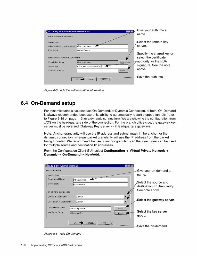
Figure 6-5 Add the authentication information
6.4 On-Demand setupFor dynamic tunnels, you can use On-Demand, or Dynamic Connection, or both. On-Demand is always recommended because of its ability to automatically restart stopped tunnels (refer to Figure 6-19 on page 113 for a dynamic connection). We are showing the configuration from z/OS on the headquarters side of the connection. For the branch office side, the gateway key server must be reversed (Gateway Key Server -> #Headquarters gateway).
Note: Anchor granularity will use the IP address and subnet mask in the anchor for the dynamic connection, whereas packet granularity will use the IP address from the packet being tunneled. We recommend the use of anchor granularity so that one tunnel can be used for multiple source and destination IP addresses.
From the Configuration Client GUI, select Configuration -> Virtual Private Network -> Dynamic -> On-Demand -> New/Add.
Figure 6-6 Add On-demand
Give your auth info a name.
Specify the shared key or select the certificate authority for the RSA signature. See the note above.
Select the remote key server.
Save the auth info.
Give your on-demand a name.
Select the gateway server.
Select the key server group.Select the key server group.
Select the gateway server.Select the gateway server.
Save the on-demand.
Select the source and destination IP Granularity. See note above.
100 Implementing VPNs in a z/OS Environment

6.5 VPN Filter setupThe VPN filters define the data and tunnel endpoints, control which data will be tunneled, and relate it to a dynamic VPN tunnel for the data management attributes. The data endpoints, rule, and service must be identically configured on the branch office and headquarters side; only the connection will differ (refer to “Connections” on page 113).
There are seven components of a VPN filter setup:
� Network objects� IPSec Rules� Data Rules� IPSec Service� Data Service� Dynamic Connection (optional)� Connections
6.5.1 Network objectsNetwork objects are required for the data endpoints and the tunnel endpoints so that filters can be generated for the traffic that must be allowed to both.
Since we are simulating this scenario in a lab environment, all of the IP addresses being used are private IP addresses. If this tunnel was over the public network, the gateway IP addresses would have to be public IP addresses routable over the Internet.
Note: Be careful how you specify groups for your data endpoints, or you may get multiple tunnels instead of the one you intended. For instance, using an IP address and subnet mask combination of 9.12.6.0/255.255.255.128 will generate one tunnel for the 128 IP addresses. However, if you create a network group and list the 128 IP addresses, you will get a separate tunnel for each, even though all the tunnels are between the same two gateways in this example.
From the Configuration Client GUI, select Configuration -> Network Objects -> New/Add.
Chapter 6. Configuring z/OS Dynamic tunnels - branch office example 101
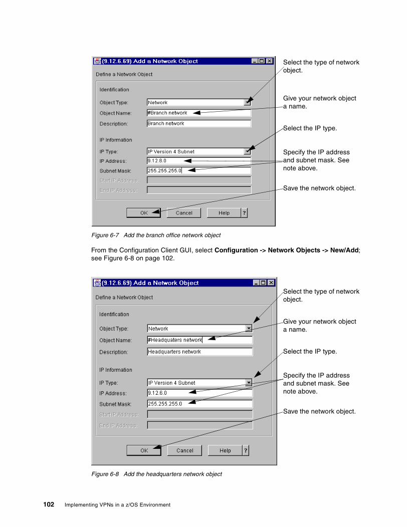
Figure 6-7 Add the branch office network object
From the Configuration Client GUI, select Configuration -> Network Objects -> New/Add; see Figure 6-8 on page 102.
Figure 6-8 Add the headquarters network object
Save the network object.
Give your network object a name.
Specify the IP address and subnet mask. See note above.
Select the IP type.
Select the type of network object.
Save the network object.
Give your network object a name.
Specify the IP address and subnet mask. See note above.
Select the type of network object.
Select the IP type.
102 Implementing VPNs in a z/OS Environment
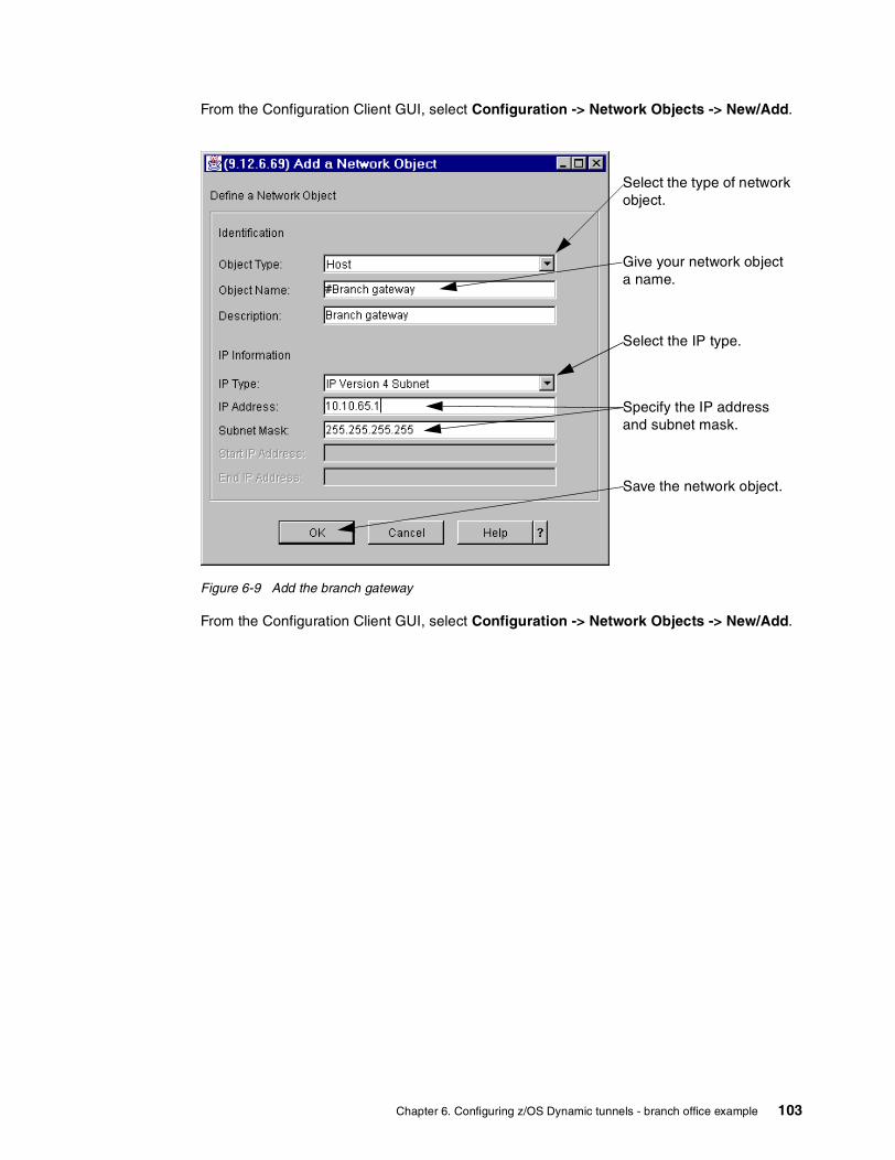
From the Configuration Client GUI, select Configuration -> Network Objects -> New/Add.
Figure 6-9 Add the branch gateway
From the Configuration Client GUI, select Configuration -> Network Objects -> New/Add.
Save the network object.
Select the type of network object.
Give your network object a name.
Specify the IP address and subnet mask.
Select the IP type.
Chapter 6. Configuring z/OS Dynamic tunnels - branch office example 103
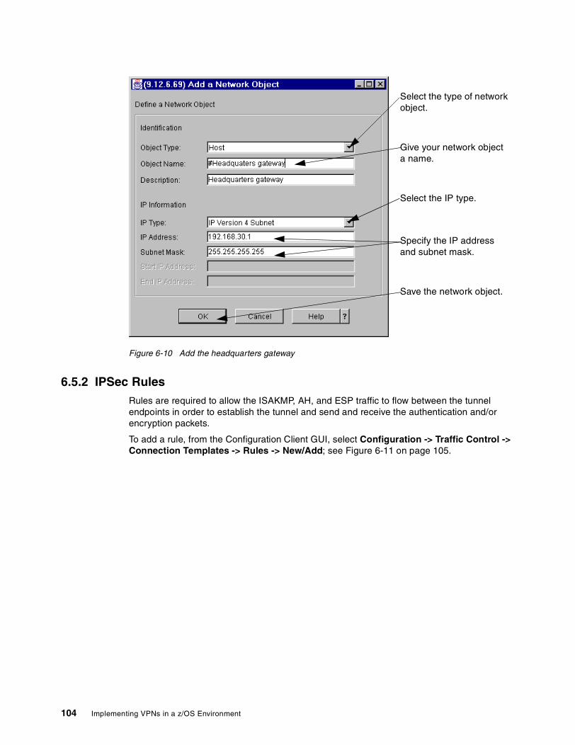
Figure 6-10 Add the headquarters gateway
6.5.2 IPSec RulesRules are required to allow the ISAKMP, AH, and ESP traffic to flow between the tunnel endpoints in order to establish the tunnel and send and receive the authentication and/or encryption packets.
To add a rule, from the Configuration Client GUI, select Configuration -> Traffic Control -> Connection Templates -> Rules -> New/Add; see Figure 6-11 on page 105.
Save the network object.
Select the type of network object.
Give your network object a name.
Specify the IP address and subnet mask.
Select the IP type.
104 Implementing VPNs in a z/OS Environment
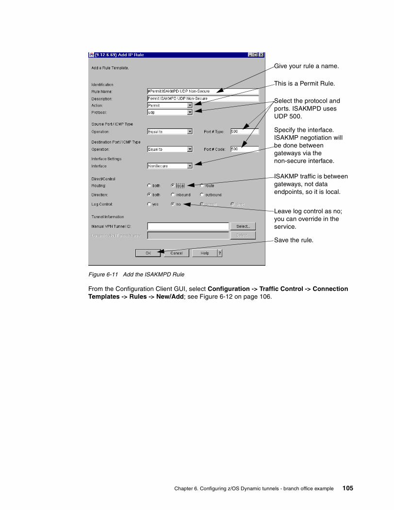
Figure 6-11 Add the ISAKMPD Rule
From the Configuration Client GUI, select Configuration -> Traffic Control -> Connection Templates -> Rules -> New/Add; see Figure 6-12 on page 106.
ISAKMP traffic is between gateways, not data endpoints, so it is local.
This is a Permit Rule.
Specify the interface. ISAKMP negotiation will be done between gateways via the non-secure interface.
Select the protocol and ports. ISAKMPD uses UDP 500.
Leave log control as no; you can override in the service.
Save the rule.
Give your rule a name.
Chapter 6. Configuring z/OS Dynamic tunnels - branch office example 105
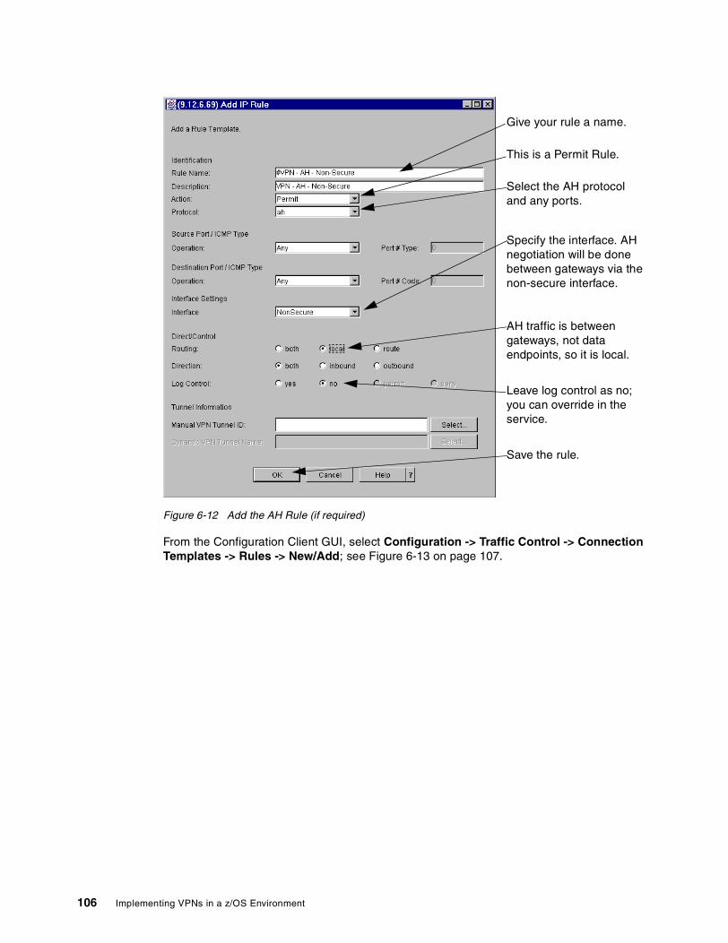
Figure 6-12 Add the AH Rule (if required)
From the Configuration Client GUI, select Configuration -> Traffic Control -> Connection Templates -> Rules -> New/Add; see Figure 6-13 on page 107.
AH traffic is between gateways, not data endpoints, so it is local.
This is a Permit Rule.
Specify the interface. AH negotiation will be done between gateways via the non-secure interface.
Select the AH protocol and any ports.
Leave log control as no; you can override in the service.
Save the rule.
Give your rule a name.
106 Implementing VPNs in a z/OS Environment
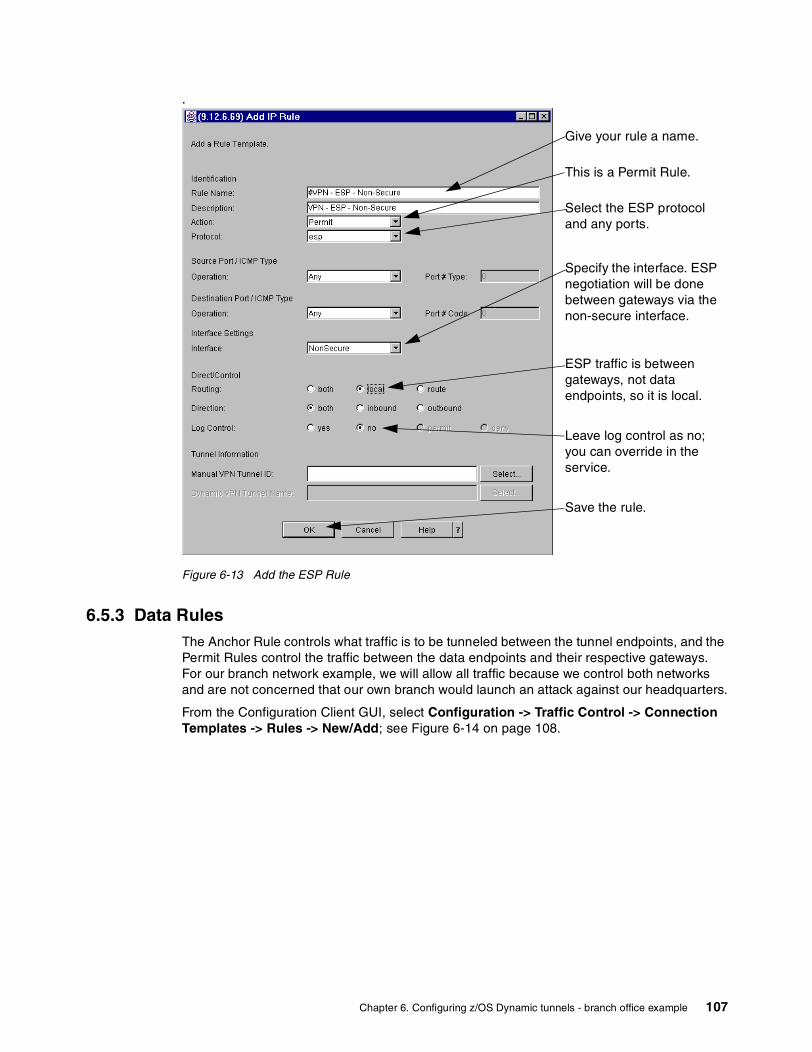
.
Figure 6-13 Add the ESP Rule
6.5.3 Data RulesThe Anchor Rule controls what traffic is to be tunneled between the tunnel endpoints, and the Permit Rules control the traffic between the data endpoints and their respective gateways. For our branch network example, we will allow all traffic because we control both networks and are not concerned that our own branch would launch an attack against our headquarters.
From the Configuration Client GUI, select Configuration -> Traffic Control -> Connection Templates -> Rules -> New/Add; see Figure 6-14 on page 108.
ESP traffic is between gateways, not data endpoints, so it is local.
This is a Permit Rule.
Specify the interface. ESP negotiation will be done between gateways via the non-secure interface.
Select the ESP protocol and any ports.
Leave log control as no; you can override in the service.
Save the rule.
Give your rule a name.
Chapter 6. Configuring z/OS Dynamic tunnels - branch office example 107
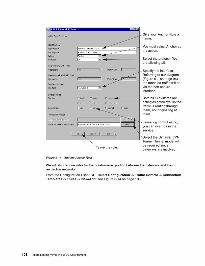
Figure 6-14 Add the Anchor Rule
We will also require rules for the non-tunneled portion between the gateways and their respective networks.
From the Configuration Client GUI, select Configuration -> Traffic Control -> Connection Templates -> Rules -> New/Add; see Figure 6-14 on page 108.
Both z/OS systems are acting as gateways, so the traffic is routing through them, not originating at them.
You must select Anchor as the action.
Specify the interface. Referring to our diagram (Figure 6-1 on page 96), the tunneled traffic will be via the non-secure interface.
Select the protocol. We are allowing all.
Leave log control as no; you can override in the service.
Select the Dynamic VPN Tunnel. Tunnel mode will be required since gateways are involved.
Save the rule.
Give your Anchor Rule a name.
108 Implementing VPNs in a z/OS Environment

Figure 6-15 Add the inbound non-tunneled Rule
From the Configuration Client GUI, select Configuration -> Traffic Control -> Connection Templates -> Rules -> New/Add; see Figure 6-16 on page 110.
Both z/OS systems are acting as gateways, so the traffic is routing through them, not originating at them.
Select the protocol. We are allowing all.
This is the inbound rule.
You must select Permit as the action.
Give your rule a name.
Specify the interface. Referring to our diagram (Figure 6-1 on page 96), the non-tunneled traffic will be via the secure interface.
Leave log control as no; you can override in the service.
Save the rule.
Chapter 6. Configuring z/OS Dynamic tunnels - branch office example 109
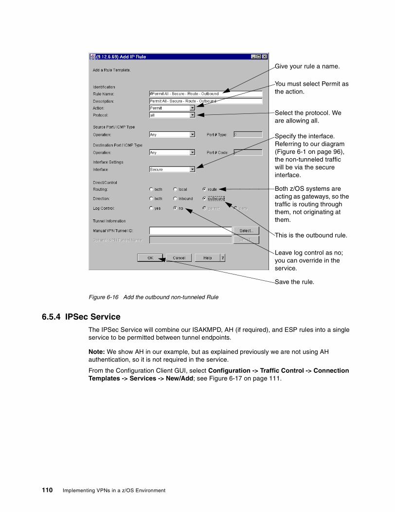
Figure 6-16 Add the outbound non-tunneled Rule
6.5.4 IPSec ServiceThe IPSec Service will combine our ISAKMPD, AH (if required), and ESP rules into a single service to be permitted between tunnel endpoints.
Note: We show AH in our example, but as explained previously we are not using AH authentication, so it is not required in the service.
From the Configuration Client GUI, select Configuration -> Traffic Control -> Connection Templates -> Services -> New/Add; see Figure 6-17 on page 111.
Both z/OS systems are acting as gateways, so the traffic is routing through them, not originating at them.
Select the protocol. We are allowing all.
This is the outbound rule.
You must select Permit as the action.
Give your rule a name.
Specify the interface. Referring to our diagram (Figure 6-1 on page 96), the non-tunneled traffic will be via the secure interface.
Leave log control as no; you can override in the service.
Save the rule.
110 Implementing VPNs in a z/OS Environment
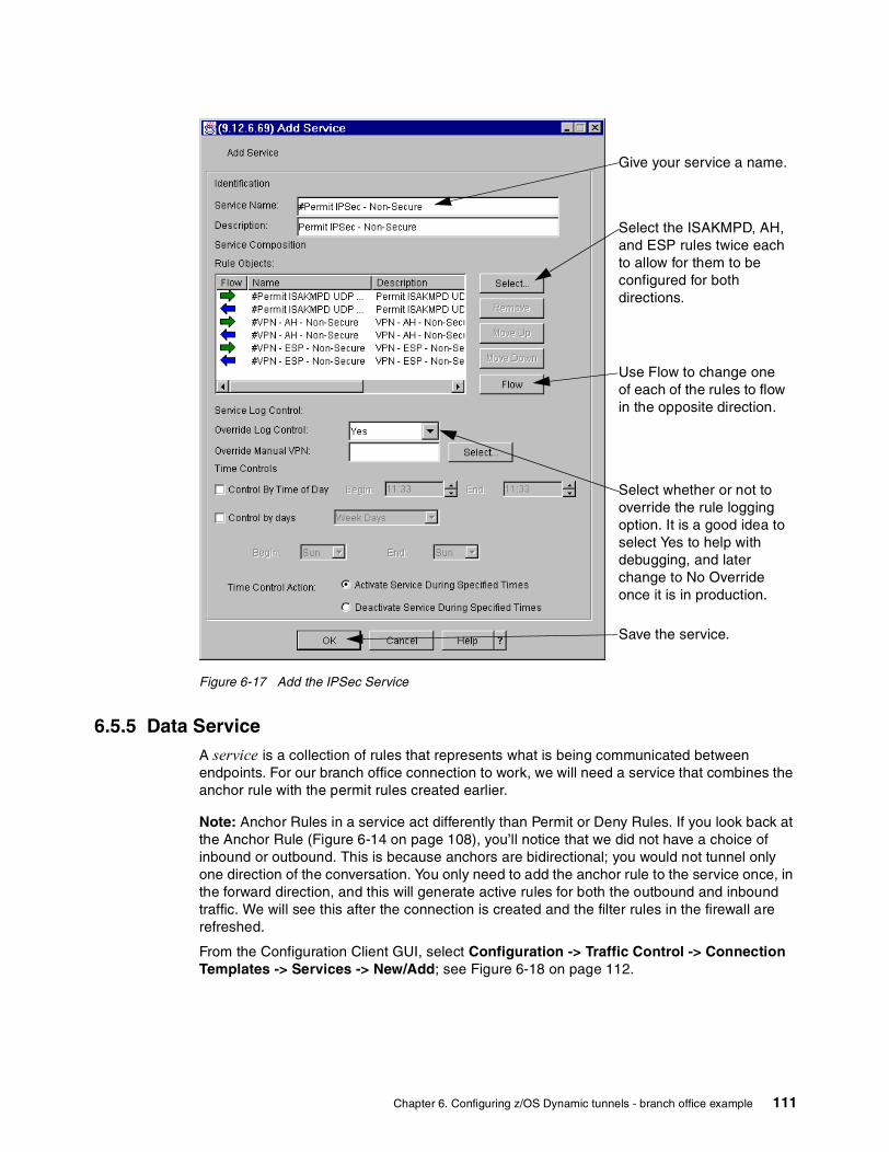
Figure 6-17 Add the IPSec Service
6.5.5 Data ServiceA service is a collection of rules that represents what is being communicated between endpoints. For our branch office connection to work, we will need a service that combines the anchor rule with the permit rules created earlier.
Note: Anchor Rules in a service act differently than Permit or Deny Rules. If you look back at the Anchor Rule (Figure 6-14 on page 108), you’ll notice that we did not have a choice of inbound or outbound. This is because anchors are bidirectional; you would not tunnel only one direction of the conversation. You only need to add the anchor rule to the service once, in the forward direction, and this will generate active rules for both the outbound and inbound traffic. We will see this after the connection is created and the filter rules in the firewall are refreshed.
From the Configuration Client GUI, select Configuration -> Traffic Control -> Connection Templates -> Services -> New/Add; see Figure 6-18 on page 112.
Select the ISAKMPD, AH, and ESP rules twice each to allow for them to be configured for both directions.
Give your service a name.
Select whether or not to override the rule logging option. It is a good idea to select Yes to help with debugging, and later change to No Override once it is in production.
Save the service.
Use Flow to change one of each of the rules to flow in the opposite direction.
Chapter 6. Configuring z/OS Dynamic tunnels - branch office example 111

Figure 6-18 Add the branch office service
6.5.6 Dynamic Connection (optional)A Dynamic Connection can be used to either manually start a dynamic VPN tunnel, or have one start automatically when the TCP/IP stack starts. Dynamic Connection can be used in conjunction with On-Demand, but we recommend that you do not use Dynamic Connections by themselves. The limitation of Dynamic Connection without On-Demand is that if the tunnel stops for any reason, it must be manually restarted. On-Demand tunnels will attempt to restart a stopped tunnel each time a packet matches the associated connection or connections.
We are showing the configuration from z/OS on the headquarters side of the connection. For the branch office side, the source and destination must be reversed and the remote key server must be reversed.
Note: One difficulty with Dynamic Connection is that the values you specify for the source, destination, protocol, and ports must match (or be a subset of) the corresponding Anchor Rule, so use extra care when entering these values.
Select the anchor rule we just created (see note above). Then select the inbound and outbound permit rules. Order is not important because none of the rules overlap.
Give your service a name.
Select whether or not to override the rule logging option. It is a good idea to select Yes to help with debugging, and later change to No Override once it is in production.
Save the service.
Use Flow to change the outbound rule direction to be opposite to the inbound (think of the left side of the arrow as the source, and the right as the destination when adding a service to a connection).
112 Implementing VPNs in a z/OS Environment

From the Configuration Client GUI, select Configuration -> Virtual Private Network -> Dynamic -> Dynamic Connection Setup/Activation -> New/Add; see Figure 6-19.
Figure 6-19 Add the Dynamic Connection
6.5.7 ConnectionsThe connections will put the data endpoints together with the service to complete the definition.
All of the configuration added thus far has no effect on the operation of the Firewall Technologies. Once the connections are defined and the filters refreshed, all data for the branch office must be tunneled through the gateways. If the traffic is already flowing untunneled, it will cease to flow until the other gateway’s configuration is also complete. We recommend that you complete all configuration on both endpoints up to this point before proceeding. Complete this last step when it is convenient to disrupt traffic flow.
We are showing the configuration from z/OS on the headquarters side of the connection. For the branch office side, the source and destination must be reversed.
Note: The order of connections is very important. The filters generated from the connections will be in the same order as the connections. For each IP packet, the firewall starts at the top of the active filters and compares against each one until it finds a match. Once a match is found, it applies the filter and continues with the next packet. For example, if you had an anchor for all traffic between source A and destination B before the permit for IPSec traffic between source A and destination B, your tunnel could never activate because the first rule would be for tunneled traffic, and there is no tunnel until IPSec negotiation completes.
Give your Dynamic Connection a name.
Select the Protocol, Source and Destination Ports (see note above).
Select the data source and destination (not the tunnel source and destination).
Select whether or not the tunnel should automatically activate when TCP/IP starts.
Select the Remote Key Server.
Select the Key Server Group.Save the Dynamic
Connection.
Chapter 6. Configuring z/OS Dynamic tunnels - branch office example 113

Since our tunnel endpoints are not the same as our data endpoints in this example, we don’t have this problem. We recommend that you always order IPSec connections before anchor connections to avoid this issue.
From the Configuration Client GUI, select Configuration -> Traffic Control -> Connection Setup -> New/Add.
Figure 6-20 Add the IPSec connection
From the Configuration Client GUI, select Configuration -> Traffic Control -> Connection Setup -> New/Add; see Figure 6-21 on page 115.
Select the IPSec source and destination network objects.
Give your connection a name.
Save the connection.
Select the IPSec service created earlier.
114 Implementing VPNs in a z/OS Environment
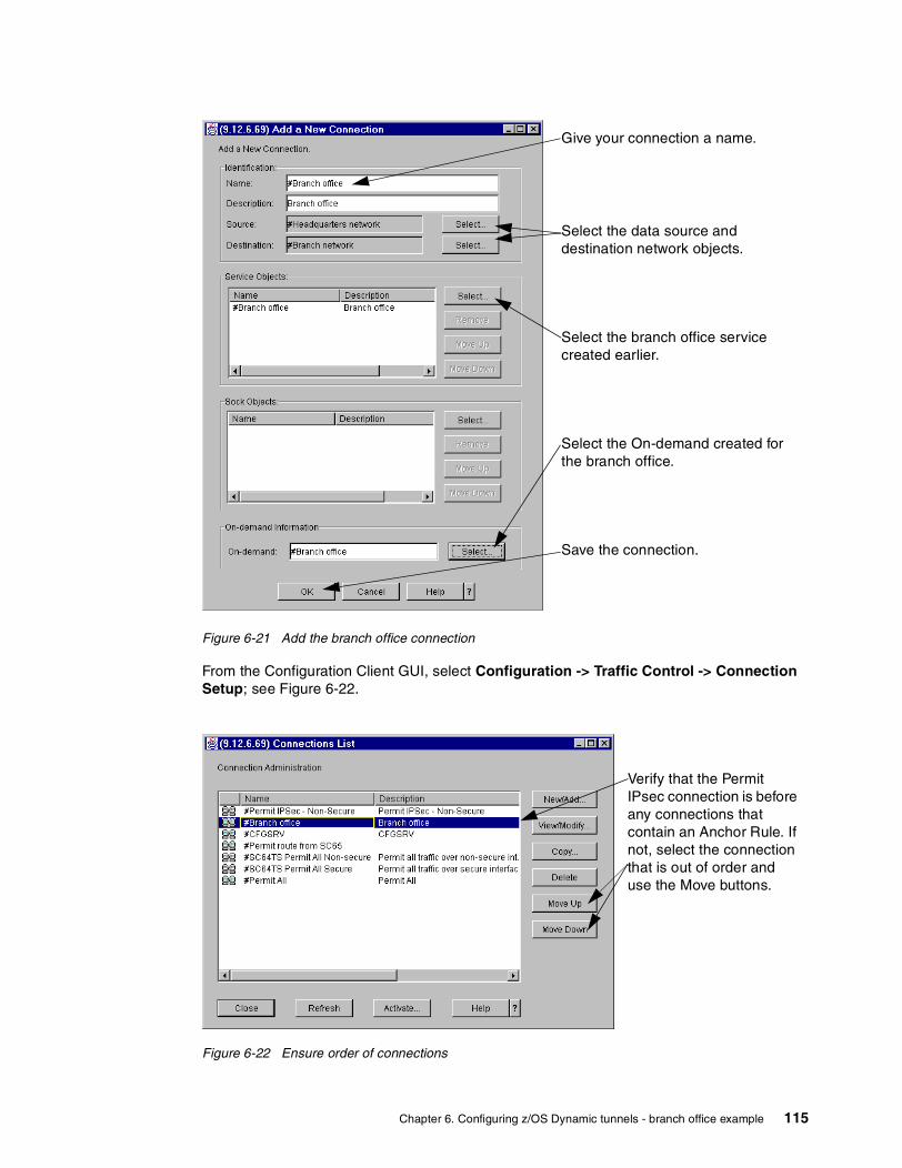
Figure 6-21 Add the branch office connection
From the Configuration Client GUI, select Configuration -> Traffic Control -> Connection Setup; see Figure 6-22.
Figure 6-22 Ensure order of connections
Select the data source and destination network objects.
Give your connection a name.
Select the On-demand created for the branch office.
Save the connection.
Select the branch office service created earlier.
Verify that the Permit IPsec connection is before any connections that contain an Anchor Rule. If not, select the connection that is out of order and use the Move buttons.
Chapter 6. Configuring z/OS Dynamic tunnels - branch office example 115

You can now select Configuration -> Traffic Control -> Connection Activation, specify Regenerate Filter and Socks and Activate, then Execute to activate the new filters.
The resulting filters are logged to syslogd with a message ID of ICA1078i. The filters for the IPSec connection is shown in Figure 6-23. The six filters for the IPSec connection correspond with the three rules added to the service twice with reverse flow.
Figure 6-23 IPSec filters
The filters for the branch office connection are shown in Figure 6-24. The branch office connection generated four filters from the three rules because the Anchor Rule generates both an inbound and outbound filter.
Figure 6-24 Data filters
You’ll notice that the filters generated from the anchor rule (#:8 and #:9) have an associated tunnel name, as well.
#:1 permit 192.168.30.1 255.255.255.255 10.10.65.1 255.255.255.255 udp eq 500 eq 500 non-secure local both l=y f=y s=m d=m ; #:2 permit 10.10.65.1 255.255.255.255 192.168.30.1 255.255.255.255 udp eq 500 eq 500 non-secure local both l=y f=y s=m d=m ; #:3 permit 192.168.30.1 255.255.255.255 10.10.65.1 255.255.255.255 ah any 0 any 0 non-secure local both l=y f=y s=m d=m ; #:4 permit 10.10.65.1 255.255.255.255 192.168.30.1 255.255.255.255 ah any 0 any 0 non-secure local both l=y f=y s=m d=m ; #:5 permit 192.168.30.1 255.255.255.255 10.10.65.1 255.255.255.255 esp any 0 any 0 non-secure local both l=y f=y s=m d=m ; #:6 permit 10.10.65.1 255.255.255.255 192.168.30.1 255.255.255.255 esp any 0 any 0 non-secure local both l=y f=y s=m d=m ;
#:7 permit 9.12.6.0 255.255.255.0 9.12.8.0 255.255.255.0 all any 0 any 0 secure route inbound l=y f=y s=m d=m ; #:8 permit 9.12.6.0 255.255.255.0 9.12.8.0 255.255.255.0 all any 0 any 0 non-secure route outbound l=y f=y t=503:502:508:509:510:502:0 s=m d=m g=aa; #:9 permit 9.12.8.0 255.255.255.0 9.12.6.0 255.255.255.0 all any 0 any 0 non-secure route inbound l=y f=y t=503:502:508:509:510:502:0 s=m d=m g=aa; #:10 permit 9.12.8.0 255.255.255.0 9.12.6.0 255.255.255.0 all any 0 any 0 secure route outbound l=y f=y s=m d=m ;
116 Implementing VPNs in a z/OS Environment
Chapter 7. Configuring z/OS Dynamic tunnels: business partner example
This chapter provides detailed configuration steps for defining dynamic tunnels. z/OS Firewall Technologies uses industry-standard protocols and can interoperate with products from other vendors; however, we will focus specifically on the z/OS perspective.
The configuration client (GUI) distinguishes between sample objects that come pre configured in z/OS Firewall Technologies and locally defined objects by the color of the icon to the left of the object name: red for pre configured objects, blue for locally defined objects. In our examples, we also precede our object names with a pound sign (#) to help differentiate and to have them sort to the top of each list.
7
© Copyright IBM Corp. 2001 117
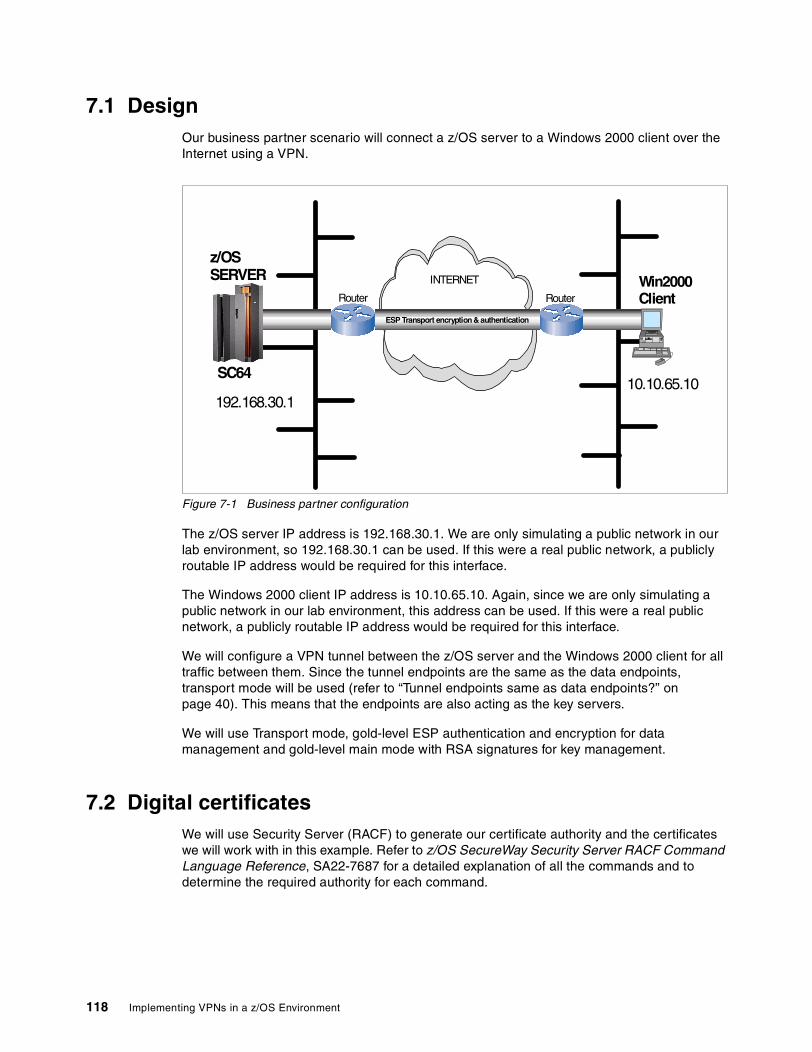
7.1 DesignOur business partner scenario will connect a z/OS server to a Windows 2000 client over the Internet using a VPN.
Figure 7-1 Business partner configuration
The z/OS server IP address is 192.168.30.1. We are only simulating a public network in our lab environment, so 192.168.30.1 can be used. If this were a real public network, a publicly routable IP address would be required for this interface.
The Windows 2000 client IP address is 10.10.65.10. Again, since we are only simulating a public network in our lab environment, this address can be used. If this were a real public network, a publicly routable IP address would be required for this interface.
We will configure a VPN tunnel between the z/OS server and the Windows 2000 client for all traffic between them. Since the tunnel endpoints are the same as the data endpoints, transport mode will be used (refer to “Tunnel endpoints same as data endpoints?” on page 40). This means that the endpoints are also acting as the key servers.
We will use Transport mode, gold-level ESP authentication and encryption for data management and gold-level main mode with RSA signatures for key management.
7.2 Digital certificatesWe will use Security Server (RACF) to generate our certificate authority and the certificates we will work with in this example. Refer to z/OS SecureWay Security Server RACF Command Language Reference, SA22-7687 for a detailed explanation of all the commands and to determine the required authority for each command.
z/OSSERVER
Router
SC64
192.168.30.1
Win2000Client
INTERNET
ESP Transport encryption & authentication
Router
10.10.65.10
118 Implementing VPNs in a z/OS Environment

NOTE: the values for the parameters supplied via the RACDCERT command are case-sensitive. This requires special care be taken when issuing the commands. We recommend saving your commands in a Partitioned Data Set (PDS) with CAPS OFF to execute as CLISTs. The first line of each CLIST must be “CONTROL ASIS” to ensure the values are not translated to upper case when the command is executed, even though they are saved as mixed case.
There are eight RACF commands we must use to define the required objects:
� Create the key ring
� Generate a Certificate Authority (CA) certificate
� Generate the Windows 2000 client certificate
� Generate the z/OS server certificate
� Connect the CA certificate to the key ring
� Connect the z/OS server certificate to the key ring
� Export the CA certificate
� Export the Windows 2000 certificate
7.2.1 Create the key ringz/OS Firewall Technologies supports a single key ring to hold all the digital certificates required for RSA Signature authentication (refer to “Key ring” on page 123). If the ISAKMPD daemon is already running when the key ring is created, it will have to be recycled in order to enable digital certificates. To match the pre configured value, it must be lower case!
Example 7-1 Create the key ring
CONTROL ASIS RACDCERT ID(FWKERN) ADDRING(ikekeyring)
7.2.2 Generate a Certificate Authority (CA) certificateThe CA certificate will be used to sign the z/OS server and Windows 2000 client certificates.
Example 7-2 Generate a CA certificate
CONTROL ASIS RACDCERT CERTAUTH GENCERT SUBJECTSDN(CN('z/OS RACF CA') O('IBM') + OU('ITSO') C('us')) WITHLABEL('z/OS RACF CA')
7.2.3 Generate the Windows 2000 client certificateThe Windows 2000 client certificate will be installed in the business partner’s Windows 2000 client that will be connecting to the z/OS Server. It is signed with the CA certificate we just generated.
Example 7-3 Generate the Win2000 client certificate
CONTROL ASIS RACDCERT ID(FWKERN) GENCERT SUBJECTSDN(CN('Win2000 Client') O('IBM') + OU('ITSO') C('us')) WITHLABEL('Win2000 Client') + SIGNWITH(CERTAUTH LABEL('z/OS RACF CA')) + KEYUSAGE(HANDSHAKE) + ALTNAME(IP(10.10.65.10))
Chapter 7. Configuring z/OS Dynamic tunnels: business partner example 119
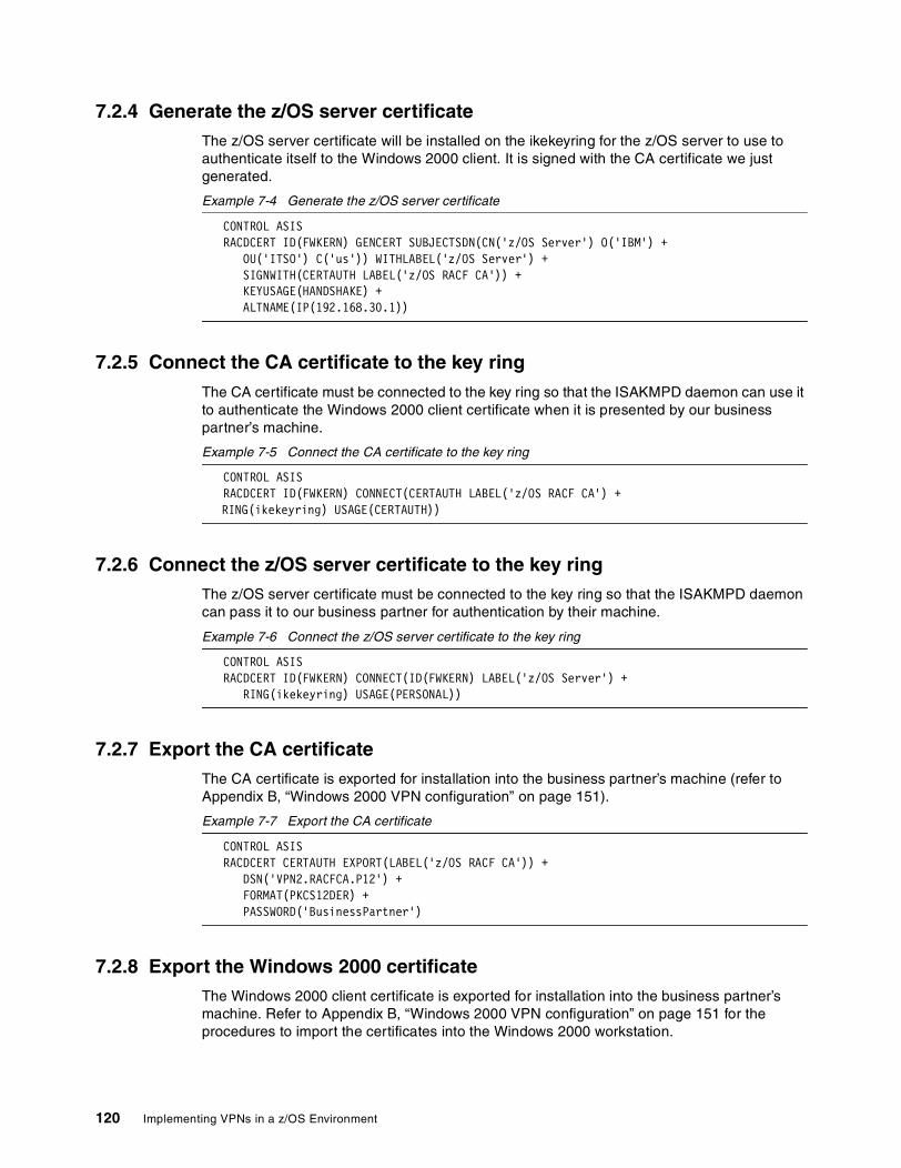
7.2.4 Generate the z/OS server certificateThe z/OS server certificate will be installed on the ikekeyring for the z/OS server to use to authenticate itself to the Windows 2000 client. It is signed with the CA certificate we just generated.
Example 7-4 Generate the z/OS server certificate
CONTROL ASIS RACDCERT ID(FWKERN) GENCERT SUBJECTSDN(CN('z/OS Server') O('IBM') + OU('ITSO') C('us')) WITHLABEL('z/OS Server') + SIGNWITH(CERTAUTH LABEL('z/OS RACF CA')) + KEYUSAGE(HANDSHAKE) + ALTNAME(IP(192.168.30.1))
7.2.5 Connect the CA certificate to the key ringThe CA certificate must be connected to the key ring so that the ISAKMPD daemon can use it to authenticate the Windows 2000 client certificate when it is presented by our business partner’s machine.
Example 7-5 Connect the CA certificate to the key ring
CONTROL ASIS RACDCERT ID(FWKERN) CONNECT(CERTAUTH LABEL('z/OS RACF CA') +
RING(ikekeyring) USAGE(CERTAUTH))
7.2.6 Connect the z/OS server certificate to the key ringThe z/OS server certificate must be connected to the key ring so that the ISAKMPD daemon can pass it to our business partner for authentication by their machine.
Example 7-6 Connect the z/OS server certificate to the key ring
CONTROL ASIS RACDCERT ID(FWKERN) CONNECT(ID(FWKERN) LABEL('z/OS Server') + RING(ikekeyring) USAGE(PERSONAL))
7.2.7 Export the CA certificateThe CA certificate is exported for installation into the business partner’s machine (refer to Appendix B, “Windows 2000 VPN configuration” on page 151).
Example 7-7 Export the CA certificate
CONTROL ASIS RACDCERT CERTAUTH EXPORT(LABEL('z/OS RACF CA')) + DSN('VPN2.RACFCA.P12') + FORMAT(PKCS12DER) + PASSWORD('BusinessPartner')
7.2.8 Export the Windows 2000 certificateThe Windows 2000 client certificate is exported for installation into the business partner’s machine. Refer to Appendix B, “Windows 2000 VPN configuration” on page 151 for the procedures to import the certificates into the Windows 2000 workstation.
120 Implementing VPNs in a z/OS Environment

Example 7-8 Export the Windows 2000 client certificate
CONTROL ASIS RACDCERT ID(FWKERN) EXPORT(LABEL('Win2000 Client')) + DSN('VPN2.CLIENT.P12') + FORMAT(PKCS12DER) + PASSWORD('BusinessPartner')
7.3 Key server setupThe Key Server configuration dictates how the peers will identify themselves to one another and which key management policy they will use. There are two components of key server setup:
� Key servers
� Key server group
7.3.1 Key serversThe data endpoints are the key servers. In our business partner example they will be using X500_DN authentication. Both key servers must be defined on both sides of the connection.
NOTE: The auth ID for X500_DN authentication is the Relative Distinguished Names (RDNs) from the certificate. Refer to the fwkeysrv command in z/OS SecureWay Security Server Firewall Technologies, SC24-5992 for a detailed description of how to code the RDNs.
From the configuration client GUI, select Configuration -> Virtual Private Network -> Dynamic -> Key Servers -> Key Server -> New/Add.
Figure 7-2 Add the z/OS server key server
Give your key server a name.
Specify the IP address or the host name.
Select the type of auth ID.
Save the key server.
Specify the auth ID value. See note above.
Chapter 7. Configuring z/OS Dynamic tunnels: business partner example 121

From the configuration client GUI, select Configuration -> Virtual Private Network -> Dynamic -> Key Servers -> Key Server -> New/Add.
Figure 7-3 Add the Win2000 client key server
7.3.2 Key server groupThe key server group will add the key policy that the key server pair will use. We show the configuration from the z/OS server side of the connection here. Refer to Appendix B, “Windows 2000 VPN configuration” on page 151 for the Windows 2000 configuration.
From the configuration client GUI, select Configuration -> Virtual Private Network -> Dynamic -> Key Servers -> Key Server Group -> New/Add.
Figure 7-4 Add the key server group
Give your key server a name.
Specify the IP address or the host name.
Select the type of auth ID.
Save the key server.
Specify the auth ID value.
Give your key server group a name.
Select the local key server.
Select the key policy. We created a local policy based on the pre configured sample “z/OS Main Mode - RSA Signature - Gold” for this scenario.
Select the remote key server.
Save the key server group.
122 Implementing VPNs in a z/OS Environment

7.4 Authentication data setupTunnel endpoints must authenticate themselves to one another via either preshared keys or RSA signatures (digital certificates), or both. We recommend you gain some experience using preshared keys before attempting the more complex option of using RSA signatures. If RSA signatures are going to be used, you must build the appropriate elements in Security Server first (refer to “Digital certificates” on page 118). There are three components for authentication:
� Key ring (RSA signatures only)
� Certificate authority (RSA signatures only)
� Authentication information
7.4.1 Key ringKey ring is for use with RSA signatures (digital certificates) only. If you are using preshared keys, do not select this option.
There is only one key ring per firewall instance, so this step only needs to be performed once.
From the configuration client GUI, select Configuration -> Virtual Private Network -> Dynamic -> Key Servers -> Authentication Data -> Key Ring.
Figure 7-5 Specify the RACF key ring
7.4.2 Certificate authorityCertificate authority is for use with RSA signatures (digital certificates) only. If you are using preshared keys, do not select this option.
NOTE: The RACDCERT Label that you enter must match the WITHLABEL value from the RACDCERT CERTAUTH GENCERT command if you created the certificate locally or the RACDCERT CERTAUTH ADD command if you are importing the certificate (refer to“Digital certificates” on page 118).
We will use the default values for User ID and Key Ring Name.
Save the key ring configuration.
Chapter 7. Configuring z/OS Dynamic tunnels: business partner example 123

From the configuration client GUI, select Configuration -> Virtual Private Network -> Dynamic -> Key Servers -> Authentication Data -> Certificate Authority.
Figure 7-6 Add the certificate authority
7.4.3 Authentication informationAuthentication information provides additional information that is used by the authentication method. We are using a key policy that specifies RSA signatures in this example, so it is strongly recommended that a Certificate Authority be selected for authentication.
Figure 7-7 shows the configuration from the z/OS server side of the connection. Refer to Appendix B, “Windows 2000 VPN configuration” on page 151 for the Windows 2000 configuration.
From the configuration client GUI, select Configuration -> Virtual Private Network -> Dynamic -> Key Servers -> Authentication Data -> Authentication Info -> New/Add.
Figure 7-7 Add the authentication information
7.5 On-demand setupOn-demand or dynamic connection, or both, may be used for dynamic tunnels. On-demand is always recommend because of its ability to automatically restart stopped tunnels. (Refer to Figure 7-17 on page 133 for a dynamic connection.) We are showing the configuration from the z/OS server side of the connection. Refer to Appendix B, “Windows 2000 VPN configuration” on page 151 for the Windows 2000 configuration.
Give your certificate authority a name.
Specify the RACDCERT Label. See the note above.
Save the key ring configuration.
Give your auth info a name.
Select the remote key server.
Save the auth info.
Specify the shared key or select the certificate authority for the RSA signature.
124 Implementing VPNs in a z/OS Environment
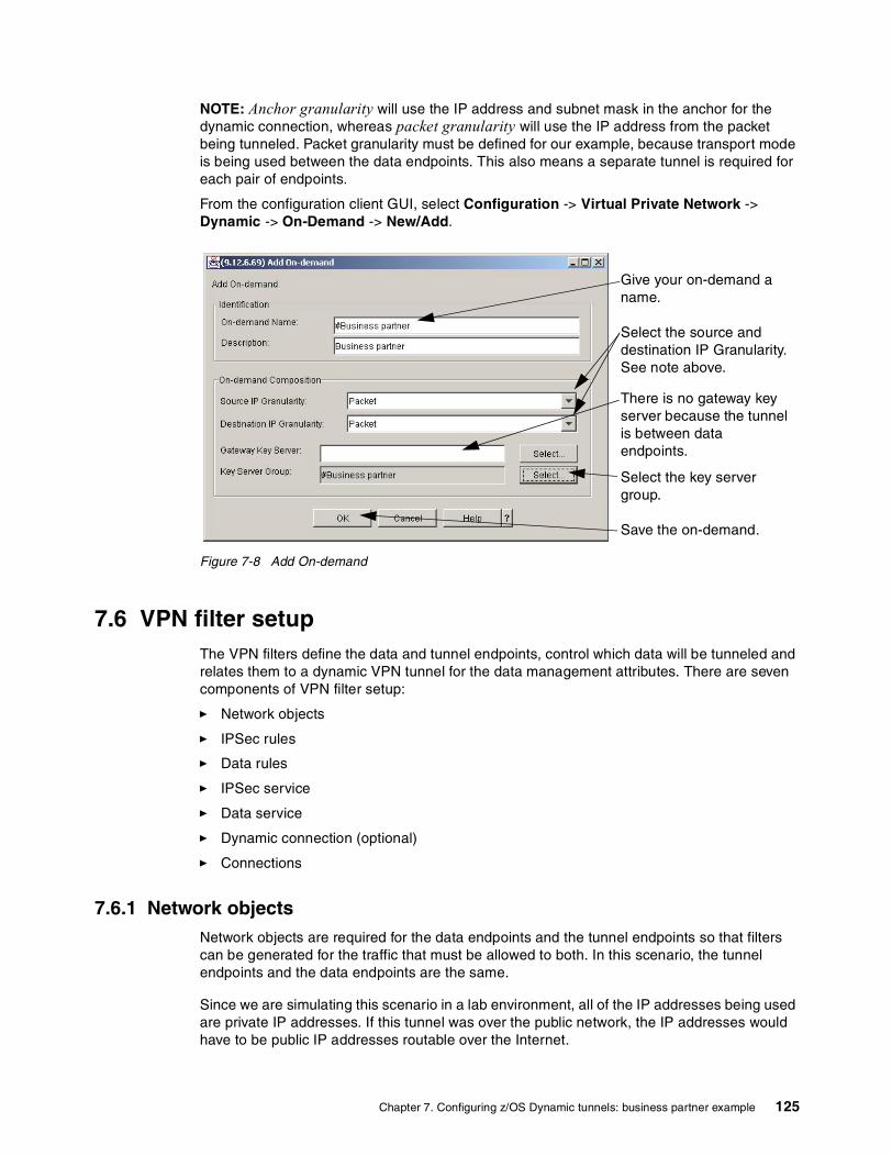
NOTE: Anchor granularity will use the IP address and subnet mask in the anchor for the dynamic connection, whereas packet granularity will use the IP address from the packet being tunneled. Packet granularity must be defined for our example, because transport mode is being used between the data endpoints. This also means a separate tunnel is required for each pair of endpoints.
From the configuration client GUI, select Configuration -> Virtual Private Network -> Dynamic -> On-Demand -> New/Add.
Figure 7-8 Add On-demand
7.6 VPN filter setupThe VPN filters define the data and tunnel endpoints, control which data will be tunneled and relates them to a dynamic VPN tunnel for the data management attributes. There are seven components of VPN filter setup:
� Network objects
� IPSec rules
� Data rules
� IPSec service
� Data service
� Dynamic connection (optional)
� Connections
7.6.1 Network objectsNetwork objects are required for the data endpoints and the tunnel endpoints so that filters can be generated for the traffic that must be allowed to both. In this scenario, the tunnel endpoints and the data endpoints are the same.
Since we are simulating this scenario in a lab environment, all of the IP addresses being used are private IP addresses. If this tunnel was over the public network, the IP addresses would have to be public IP addresses routable over the Internet.
Give your on-demand a name.
Select the key server group.
There is no gateway key server because the tunnel is between data endpoints.
Save the on-demand.
Select the source and destination IP Granularity. See note above.
Chapter 7. Configuring z/OS Dynamic tunnels: business partner example 125

From the configuration client GUI, select Configuration -> Network Objects -> New/Add.
Figure 7-9 Add the z/OS server network object
From the configuration client GUI, select Configuration -> Network Objects -> New/Add.
Figure 7-10 Add the Win2000 client network object
Save the network object.
Give your network object a name.
Specify the IP address and subnet mask.
Select the IP type.
Select the type of network object.
Save the network object.
Give your network object a name.
Specify the IP address and subnet mask.
Select the type of network object.
Select the IP type.
126 Implementing VPNs in a z/OS Environment

7.6.2 IPSec rulesRules are required to allow the ISAKMP, AH, and ESP traffic to flow between the tunnel endpoints in order to establish the tunnel and send and receive the authentication and/or encryption packets.
From the configuration client GUI, select Configuration -> Traffic Control -> Connection Templates -> Rules -> New/Add.
Figure 7-11 Add the ISAKMPD rule
ISAKMP traffic is local, it is not being routed through the z/OS server.
This is a permit rule.
Specify the interface. ISAKMP negotiation will be done via the non-secure interface.
Select the protocol and ports. ISAKMPD uses UDP 500.
Leave log control as no, you can override in the service.
Save the Rule.
Give your rule a name.
Chapter 7. Configuring z/OS Dynamic tunnels: business partner example 127

From the configuration client GUI, select Configuration -> Traffic Control -> Connection Templates -> Rules -> New/Add.
Figure 7-12 Add the AH rule (if required)
AH traffic is local, it is not being routed through the z/OS server.
This is a permit rule.
Specify the interface. AH negotiation will be done via the non-secure interface.
Select the AH protocol and any ports.
Leave log control as no, you can override in the service.
Save the Rule.
Give your rule a name.
128 Implementing VPNs in a z/OS Environment
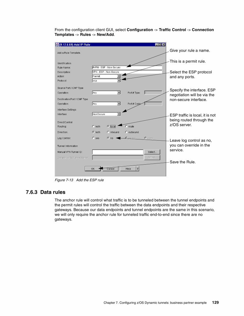
From the configuration client GUI, select Configuration -> Traffic Control -> Connection Templates -> Rules -> New/Add.
Figure 7-13 Add the ESP rule
7.6.3 Data rulesThe anchor rule will control what traffic is to be tunneled between the tunnel endpoints and the permit rules will control the traffic between the data endpoints and their respective gateways. Because our data endpoints and tunnel endpoints are the same in this scenario, we will only require the anchor rule for tunneled traffic end-to-end since there are no gateways.
ESP traffic is local, it is not being routed through the z/OS server.
This is a permit rule.
Specify the interface. ESP negotiation will be via the non-secure interface.
Select the ESP protocol and any ports.
Leave log control as no, you can override in the service.
Save the Rule.
Give your rule a name.
Chapter 7. Configuring z/OS Dynamic tunnels: business partner example 129
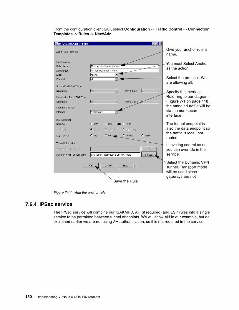
From the configuration client GUI, select Configuration -> Traffic Control -> Connection Templates -> Rules -> New/Add.
Figure 7-14 Add the anchor rule
7.6.4 IPSec serviceThe IPSec service will combine our ISAKMPD, AH (if required) and ESP rules into a single service to be permitted between tunnel endpoints. We will show AH in our example, but as explained earlier we are not using AH authentication, so it is not required in the service.
The tunnel endpoint is also the data endpoint so the traffic is local, not routed.
You must Select Anchor as the action.
Specify the interface. Referring to our diagram (Figure 7-1 on page 118), the tunneled traffic will be via the non-secure interface
Select the protocol. We are allowing all.
Leave log control as no, you can override in the service.
Select the Dynamic VPN Tunnel. Transport mode will be used since gateways are not
Save the Rule.
Give your anchor rule a name.
130 Implementing VPNs in a z/OS Environment
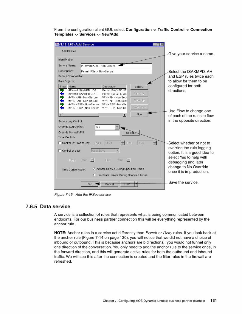
From the configuration client GUI, select Configuration -> Traffic Control -> Connection Templates -> Services -> New/Add.
Figure 7-15 Add the IPSec service
7.6.5 Data serviceA service is a collection of rules that represents what is being communicated between endpoints. For our business partner connection this will be everything represented by the anchor rule.
NOTE: Anchor rules in a service act differently than Permit or Deny rules. If you look back at the anchor rule (Figure 7-14 on page 130), you will notice that we did not have a choice of inbound or outbound. This is because anchors are bidirectional; you would not tunnel only one direction of the conversation. You only need to add the anchor rule to the service once, in the forward direction, and this will generate active rules for both the outbound and inbound traffic. We will see this after the connection is created and the filter rules in the firewall are refreshed.
Select the ISAKMPD, AH and ESP rules twice each to allow for them to be configured for both directions.
Give your service a name.
Select whether or not to override the rule logging option. It is a good idea to select Yes to help with debugging and later change to No Override once it is in production.
Save the service.
Use Flow to change one of each of the rules to flow in the opposite direction.
Chapter 7. Configuring z/OS Dynamic tunnels: business partner example 131
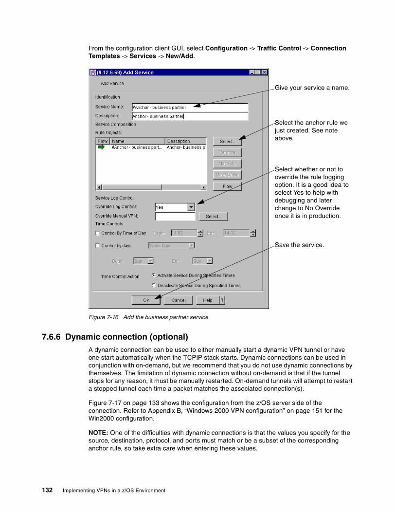
From the configuration client GUI, select Configuration -> Traffic Control -> Connection Templates -> Services -> New/Add.
Figure 7-16 Add the business partner service
7.6.6 Dynamic connection (optional)A dynamic connection can be used to either manually start a dynamic VPN tunnel or have one start automatically when the TCPIP stack starts. Dynamic connections can be used in conjunction with on-demand, but we recommend that you do not use dynamic connections by themselves. The limitation of dynamic connection without on-demand is that if the tunnel stops for any reason, it must be manually restarted. On-demand tunnels will attempt to restart a stopped tunnel each time a packet matches the associated connection(s).
Figure 7-17 on page 133 shows the configuration from the z/OS server side of the connection. Refer to Appendix B, “Windows 2000 VPN configuration” on page 151 for the Win2000 configuration.
NOTE: One of the difficulties with dynamic connections is that the values you specify for the source, destination, protocol, and ports must match or be a subset of the corresponding anchor rule, so take extra care when entering these values.
Select the anchor rule we just created. See note above.
Give your service a name.
Select whether or not to override the rule logging option. It is a good idea to select Yes to help with debugging and later change to No Override once it is in production.
Save the service.
132 Implementing VPNs in a z/OS Environment
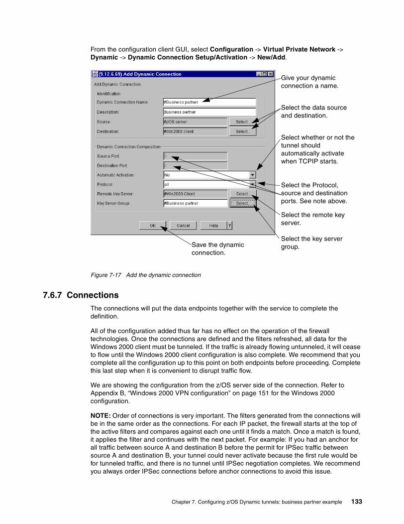
From the configuration client GUI, select Configuration -> Virtual Private Network -> Dynamic -> Dynamic Connection Setup/Activation -> New/Add.
Figure 7-17 Add the dynamic connection
7.6.7 ConnectionsThe connections will put the data endpoints together with the service to complete the definition.
All of the configuration added thus far has no effect on the operation of the firewall technologies. Once the connections are defined and the filters refreshed, all data for the Windows 2000 client must be tunneled. If the traffic is already flowing untunneled, it will cease to flow until the Windows 2000 client configuration is also complete. We recommend that you complete all the configuration up to this point on both endpoints before proceeding. Complete this last step when it is convenient to disrupt traffic flow.
We are showing the configuration from the z/OS server side of the connection. Refer to Appendix B, “Windows 2000 VPN configuration” on page 151 for the Windows 2000 configuration.
NOTE: Order of connections is very important. The filters generated from the connections will be in the same order as the connections. For each IP packet, the firewall starts at the top of the active filters and compares against each one until it finds a match. Once a match is found, it applies the filter and continues with the next packet. For example: If you had an anchor for all traffic between source A and destination B before the permit for IPSec traffic between source A and destination B, your tunnel could never activate because the first rule would be for tunneled traffic, and there is no tunnel until IPSec negotiation completes. We recommend you always order IPSec connections before anchor connections to avoid this issue.
Give your dynamic connection a name.
Select the Protocol, source and destination ports. See note above.
Select the data source and destination.
Select whether or not the tunnel should automatically activate when TCPIP starts.
Select the remote key server.
Select the key server group.Save the dynamic
connection.
Chapter 7. Configuring z/OS Dynamic tunnels: business partner example 133

From the configuration client GUI, select Configuration -> Traffic Control -> Connection Setup -> New/Add.
Figure 7-18 Add the IPSec connection
Select the IPSec source and destination network objects.
Give your connection a name.
Save the connection.
Select the IPSec service created earlier.
134 Implementing VPNs in a z/OS Environment

From the configuration client GUI, select Configuration -> Traffic Control -> Connection Setup -> New/Add.
Figure 7-19 Add the business partner connection
From the configuration client GUI, select Configuration -> Traffic Control -> Connection Setup.
Figure 7-20 Ensure order of connections
Select the data source and destination network objects.
Give your connection a name.
Select the on-demand created for the business partner.
Save the connection.
Select the business partner service created earlier.
Verify that the Permit IPsec connection is before any connections that contain an anchor rule. If not, select the connection that is out of order and use the Move buttons.
Chapter 7. Configuring z/OS Dynamic tunnels: business partner example 135
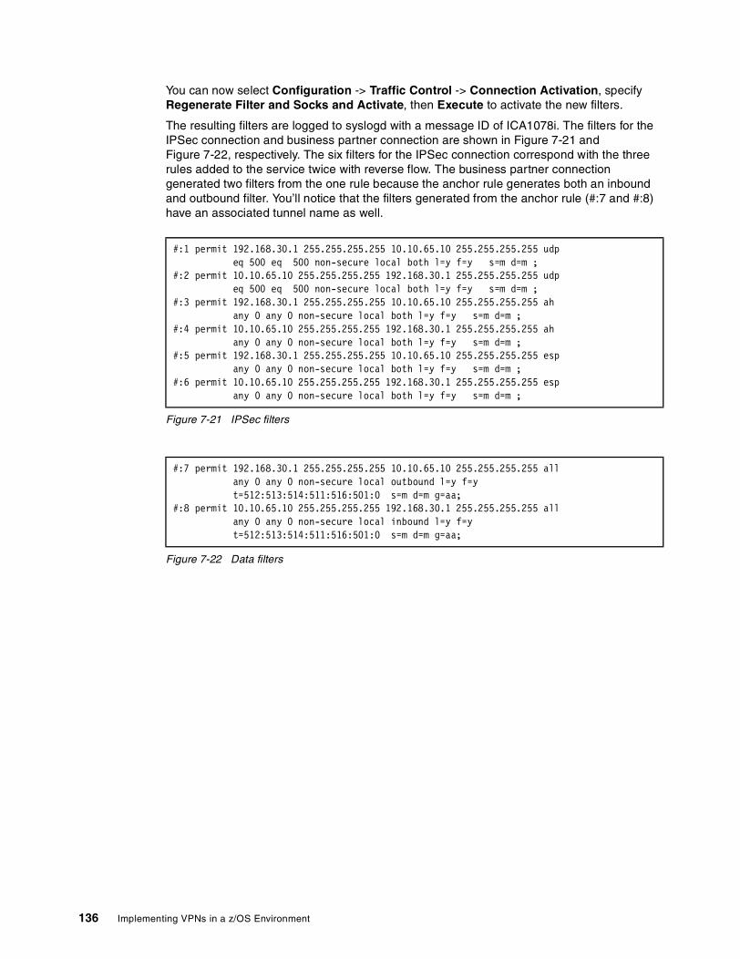
You can now select Configuration -> Traffic Control -> Connection Activation, specify Regenerate Filter and Socks and Activate, then Execute to activate the new filters.
The resulting filters are logged to syslogd with a message ID of ICA1078i. The filters for the IPSec connection and business partner connection are shown in Figure 7-21 and Figure 7-22, respectively. The six filters for the IPSec connection correspond with the three rules added to the service twice with reverse flow. The business partner connection generated two filters from the one rule because the anchor rule generates both an inbound and outbound filter. You’ll notice that the filters generated from the anchor rule (#:7 and #:8) have an associated tunnel name as well.
Figure 7-21 IPSec filters
Figure 7-22 Data filters
#:1 permit 192.168.30.1 255.255.255.255 10.10.65.10 255.255.255.255 udp eq 500 eq 500 non-secure local both l=y f=y s=m d=m ; #:2 permit 10.10.65.10 255.255.255.255 192.168.30.1 255.255.255.255 udp eq 500 eq 500 non-secure local both l=y f=y s=m d=m ; #:3 permit 192.168.30.1 255.255.255.255 10.10.65.10 255.255.255.255 ah any 0 any 0 non-secure local both l=y f=y s=m d=m ; #:4 permit 10.10.65.10 255.255.255.255 192.168.30.1 255.255.255.255 ah any 0 any 0 non-secure local both l=y f=y s=m d=m ; #:5 permit 192.168.30.1 255.255.255.255 10.10.65.10 255.255.255.255 esp any 0 any 0 non-secure local both l=y f=y s=m d=m ; #:6 permit 10.10.65.10 255.255.255.255 192.168.30.1 255.255.255.255 esp any 0 any 0 non-secure local both l=y f=y s=m d=m ;
#:7 permit 192.168.30.1 255.255.255.255 10.10.65.10 255.255.255.255 all any 0 any 0 non-secure local outbound l=y f=y t=512:513:514:511:516:501:0 s=m d=m g=aa; #:8 permit 10.10.65.10 255.255.255.255 192.168.30.1 255.255.255.255 all any 0 any 0 non-secure local inbound l=y f=y t=512:513:514:511:516:501:0 s=m d=m g=aa;
136 Implementing VPNs in a z/OS Environment
Chapter 8. VPN operation and problem determination
This chapter provides a configuration verification check list, describes basic troubleshooting procedures, and gives you tips for debugging the most common problems you may encounter during the process of setting up the firewall and configuring VPN tunnels.
A discussion of diagnostic tools, as well as examples of when and where they are applicable is also included.
8
© Copyright IBM Corp. 2001 137

8.1 Check listThe following check list, while not all-inclusive, is useful as a quick reference to help you isolate common firewall and VPN setup problems.
Firewall check list1. Verify that the TCP/IP stack was started with IPCONFIG FIREWALL, as specified in the
TCP/IP profile (see Figure 8-1).
Figure 8-1 Firewall TCP/IP stack joblog
2. After the TCP/IP stack is started, verify that the following four tasks are started, as shown in Figure 8-2.
Figure 8-2 FWKERN controlled tasks
Display Filter View Print Options Help ---------------------------------------------------------------------------------------- SDSF OUTPUT DISPLAY TCPIPD STC21230 DSID 2 LINE 0 COLUMNS 02- 133 COMMAND INPUT ===> SCROLL ===> CSR ********************************* TOP OF DATA ***************************************J E S 2 J O B L O G -- S Y S T E M S C 6 4 -- N O D E W T S C P L X 2 10.21.38 STC21230 ---- MONDAY, 12 NOV 2001 ---- 10.21.38 STC21230 IEF695I START TCPIPD WITH JOBNAME TCPIPD IS ASSIGNED TO USER STC , GROUP SYS110.21.38 STC21230 $HASP373 TCPIPD STARTED J E S 2 J O B L O G -- S Y S T E M S C 6 4 -- N O D E W T S C P L X 2 10.21.38 STC21230 ---- MONDAY, 12 NOV 2001 ---- 10.21.38 STC21230 IEF403I TCPIPD - STARTED - ASID=0050. 10.21.39 STC21230 IEE252I MEMBER CTIEZB00 FOUND IN SYS1.IBM.PARMLIB 10.21.39 STC21230 IEE252I MEMBER CTIIDS00 FOUND IN SYS1.IBM.PARMLIB 10.21.43 STC21230 EZZ0300I OPENED PROFILE FILE DD:PROFILE 10.21.43 STC21230 EZZ0309I PROFILE PROCESSING BEGINNING FOR DD:PROFILE 10.21.43 STC21230 EZZ0316I PROFILE PROCESSING COMPLETE FOR FILE DD:PROFILE 10.21.43 STC21230 EZZ0641I IP FORWARDING NOFWDMULTIPATH SUPPORT IS ENABLED 10.21.43 STC21230 EZZ0335I ICMP WILL NOT IGNORE REDIRECTS 10.21.43 STC21230 EZZ0349I FIREWALL SUPPORT IS ENABLED 10.21.43 STC21230 EZZ0337I CLAWUSEDOUBLENOP IS CLEARED 10.21.43 STC21230 EZZ0345I STOPONCLAWERROR IS DISABLED 10.21.43 STC21230 EZZ0338I TCP PORTS 1 THRU 1023 ARE RESERVED
Display Filter View Print Options Help ------------------------------------------------------------------------------ SDSF DA SC64 SC64 PAG 0 SIO 10 CPU 1/ 1 DATA SET DISPLAYED COMMAND INPUT ===> SCROLL ===> CSR NP JOBNAME StepName ProcStep JobID Owner C Pos DP Real Paging SIO ICAPSTAK ICAPSTAK GO STC21234 FWKERN IN FE 836 0.00 0.13 ICAPCFGS ICAPCFGS GO STC21232 FWKERN LO FF 3196 0.00 0.00 FWKERN FWKERN GO STC21231 FWKERN LO FF 409 0.00 0.00 ICAPIKED ICAPIKED GO STC21233 FWKERN LO FF 3624 0.00 0.00
F1=HELP F2=SPLIT F3=END F4=RETURN F5=IFIND F6=BOOK F7=UP F8=DOWN
138 Implementing VPNs in a z/OS Environment
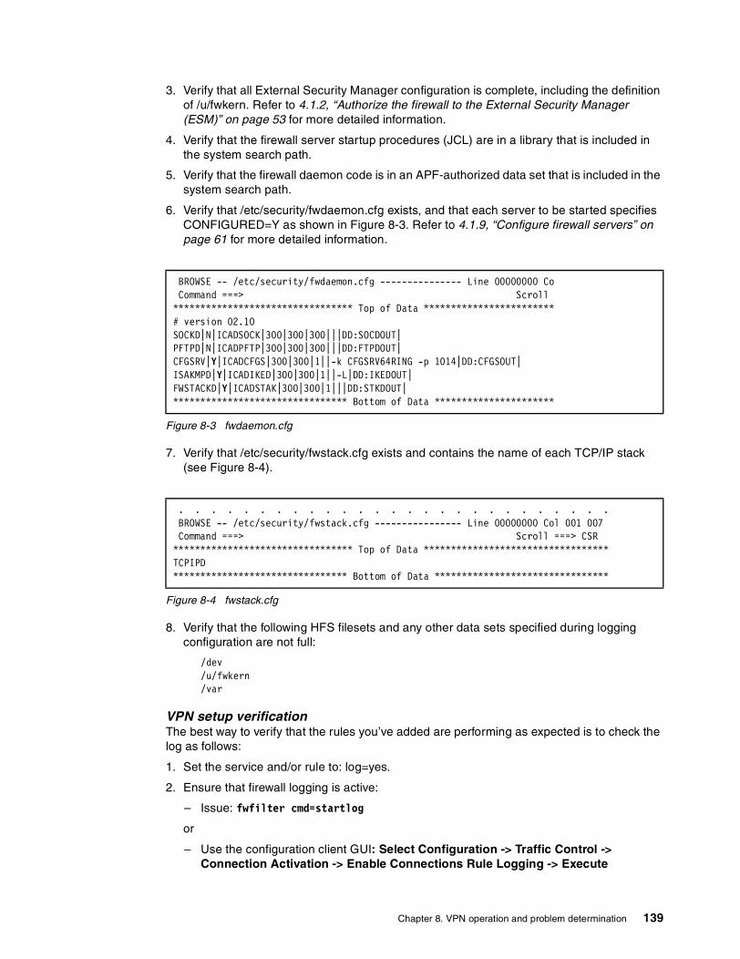
3. Verify that all External Security Manager configuration is complete, including the definition of /u/fwkern. Refer to 4.1.2, “Authorize the firewall to the External Security Manager (ESM)” on page 53 for more detailed information.
4. Verify that the firewall server startup procedures (JCL) are in a library that is included in the system search path.
5. Verify that the firewall daemon code is in an APF-authorized data set that is included in the system search path.
6. Verify that /etc/security/fwdaemon.cfg exists, and that each server to be started specifies CONFIGURED=Y as shown in Figure 8-3. Refer to 4.1.9, “Configure firewall servers” on page 61 for more detailed information.
Figure 8-3 fwdaemon.cfg
7. Verify that /etc/security/fwstack.cfg exists and contains the name of each TCP/IP stack (see Figure 8-4).
Figure 8-4 fwstack.cfg
8. Verify that the following HFS filesets and any other data sets specified during logging configuration are not full:
/dev/u/fwkern/var
VPN setup verificationThe best way to verify that the rules you’ve added are performing as expected is to check the log as follows:
1. Set the service and/or rule to: log=yes.
2. Ensure that firewall logging is active:
– Issue: fwfilter cmd=startlog
or
– Use the configuration client GUI: Select Configuration -> Traffic Control -> Connection Activation -> Enable Connections Rule Logging -> Execute
BROWSE -- /etc/security/fwdaemon.cfg --------------- Line 00000000 Co Command ===> Scroll ********************************* Top of Data ************************# version 02.10 SOCKD|N|ICADSOCK|300|300|300|||DD:SOCDOUT| PFTPD|N|ICADPFTP|300|300|300|||DD:FTPDOUT| CFGSRV|Y|ICADCFGS|300|300|1||-k CFGSRV64RING -p 1014|DD:CFGSOUT| ISAKMPD|Y|ICADIKED|300|300|1||-L|DD:IKEDOUT| FWSTACKD|Y|ICADSTAK|300|300|1|||DD:STKDOUT| ******************************** Bottom of Data **********************
. . . . . . . . . . . . . . . . . . . . . . . . . . . BROWSE -- /etc/security/fwstack.cfg ---------------- Line 00000000 Col 001 007 Command ===> Scroll ===> CSR ********************************* Top of Data ********************************** TCPIPD ******************************** Bottom of Data ********************************
Chapter 8. VPN operation and problem determination 139
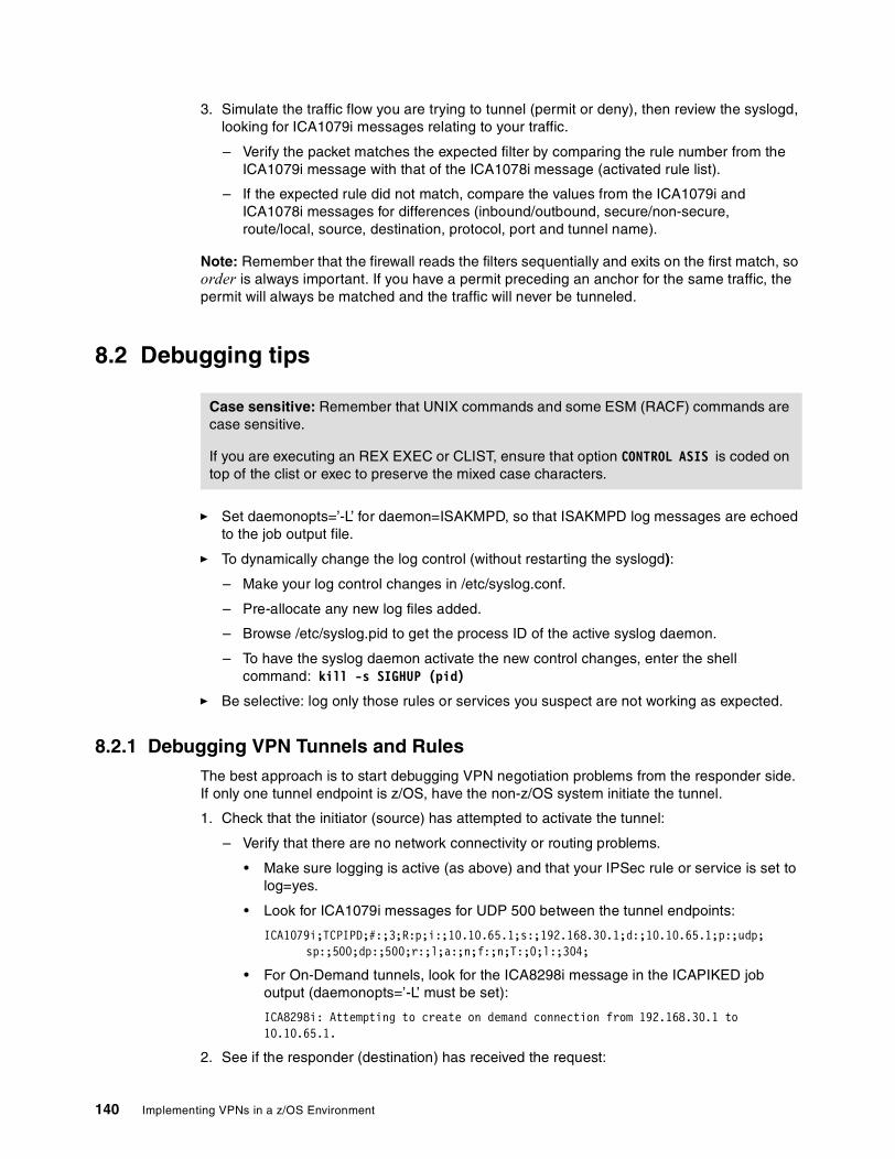
3. Simulate the traffic flow you are trying to tunnel (permit or deny), then review the syslogd, looking for ICA1079i messages relating to your traffic.
– Verify the packet matches the expected filter by comparing the rule number from the ICA1079i message with that of the ICA1078i message (activated rule list).
– If the expected rule did not match, compare the values from the ICA1079i and ICA1078i messages for differences (inbound/outbound, secure/non-secure, route/local, source, destination, protocol, port and tunnel name).
Note: Remember that the firewall reads the filters sequentially and exits on the first match, so order is always important. If you have a permit preceding an anchor for the same traffic, the permit will always be matched and the traffic will never be tunneled.
8.2 Debugging tips
� Set daemonopts=’-L’ for daemon=ISAKMPD, so that ISAKMPD log messages are echoed to the job output file.
� To dynamically change the log control (without restarting the syslogd):
– Make your log control changes in /etc/syslog.conf.
– Pre-allocate any new log files added.
– Browse /etc/syslog.pid to get the process ID of the active syslog daemon.
– To have the syslog daemon activate the new control changes, enter the shell command: kill -s SIGHUP (pid)
� Be selective: log only those rules or services you suspect are not working as expected.
8.2.1 Debugging VPN Tunnels and RulesThe best approach is to start debugging VPN negotiation problems from the responder side. If only one tunnel endpoint is z/OS, have the non-z/OS system initiate the tunnel.
1. Check that the initiator (source) has attempted to activate the tunnel:
– Verify that there are no network connectivity or routing problems.
• Make sure logging is active (as above) and that your IPSec rule or service is set to log=yes.
• Look for ICA1079i messages for UDP 500 between the tunnel endpoints:
ICA1079i;TCPIPD;#:;3;R:p;i:;10.10.65.1;s:;192.168.30.1;d:;10.10.65.1;p:;udp;sp:;500;dp:;500;r:;l;a:;n;f:;n;T:;0;l:;304;
• For On-Demand tunnels, look for the ICA8298i message in the ICAPIKED job output (daemonopts=’-L’ must be set):
ICA8298i: Attempting to create on demand connection from 192.168.30.1 to 10.10.65.1.
2. See if the responder (destination) has received the request:
Case sensitive: Remember that UNIX commands and some ESM (RACF) commands are case sensitive.
If you are executing an REX EXEC or CLIST, ensure that option CONTROL ASIS is coded on top of the clist or exec to preserve the mixed case characters.
140 Implementing VPNs in a z/OS Environment
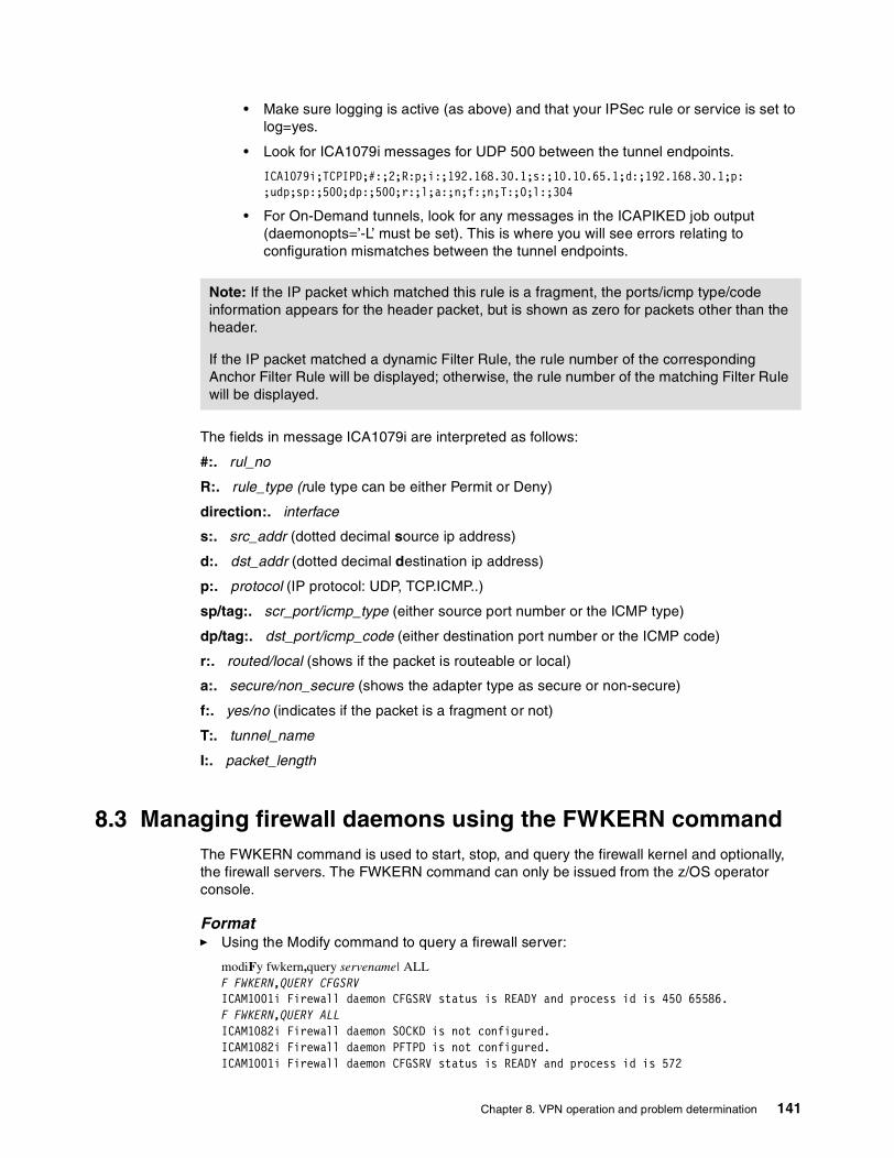
• Make sure logging is active (as above) and that your IPSec rule or service is set to log=yes.
• Look for ICA1079i messages for UDP 500 between the tunnel endpoints.
ICA1079i;TCPIPD;#:;2;R:p;i:;192.168.30.1;s:;10.10.65.1;d:;192.168.30.1;p: ;udp;sp:;500;dp:;500;r:;l;a:;n;f:;n;T:;0;l:;304
• For On-Demand tunnels, look for any messages in the ICAPIKED job output (daemonopts=’-L’ must be set). This is where you will see errors relating to configuration mismatches between the tunnel endpoints.
The fields in message ICA1079i are interpreted as follows:
#:. rul_no
R:. rule_type (rule type can be either Permit or Deny)
direction:. interface
s:. src_addr (dotted decimal source ip address)
d:. dst_addr (dotted decimal destination ip address)
p:. protocol (IP protocol: UDP, TCP.ICMP..)
sp/tag:. scr_port/icmp_type (either source port number or the ICMP type)
dp/tag:. dst_port/icmp_code (either destination port number or the ICMP code)
r:. routed/local (shows if the packet is routeable or local)
a:. secure/non_secure (shows the adapter type as secure or non-secure)
f:. yes/no (indicates if the packet is a fragment or not)
T:. tunnel_name
I:. packet_length
8.3 Managing firewall daemons using the FWKERN commandThe FWKERN command is used to start, stop, and query the firewall kernel and optionally, the firewall servers. The FWKERN command can only be issued from the z/OS operator console.
Format� Using the Modify command to query a firewall server:
modiFy fwkern,query servename| ALL F FWKERN,QUERY CFGSRV ICAM1001i Firewall daemon CFGSRV status is READY and process id is 450 65586. F FWKERN,QUERY ALL ICAM1082i Firewall daemon SOCKD is not configured. ICAM1082i Firewall daemon PFTPD is not configured. ICAM1001i Firewall daemon CFGSRV status is READY and process id is 572
Note: If the IP packet which matched this rule is a fragment, the ports/icmp type/code information appears for the header packet, but is shown as zero for packets other than the header.
If the IP packet matched a dynamic Filter Rule, the rule number of the corresponding Anchor Filter Rule will be displayed; otherwise, the rule number of the matching Filter Rule will be displayed.
Chapter 8. VPN operation and problem determination 141

ICAM1001i Firewall daemon ISAKMPD status is READY and process id isICAM10the 01i Firewall daemon FWSTACKD status is READY and process id is
� Using the Modify command to start or stop a firewall server:
modiFy FWKERN,START|STOP servernameF FWKERN,STOP CFGSRV -ICAPCFGS GO ICAPCFGS 00 2326 .00 .00 2899.0 42967 0 0 0 IEF404I ICAPCFGS - ENDED - ASID=004E. -ICAPCFGS ENDED. NAME- TOTAL CPU TIME= .00 TOTAL ELAPSED TIME=2899.0 $HASP395 ICAPCFGS ENDED ICAM1000i Firewall daemon CFGSRV has stopped. F FWKERN,START CFGSRV $HASP100 ICAPCFGS ON STCINRDR $HASP373 ICAPCFGS STARTED IEF403I ICAPCFGS - STARTED - ASID=004E.
� Start the firewall (FWKERN):
Start fwkern [, parms=‘–nofw’]S FWKERN$HASP373 FWKERN STARTEDIEF403I FWKERN - STARTED - TIME=09.26.54ICAM1057i Release 2.12.0 Service Level 0000000 Created OW49487. Created on Oct 22 ICAM1057i Release 2.12.0 Service Level OW49487. Created on Oct 22 2001. ICAM1069i Daemon CFGSRV has been started. ICAM1069i Daemon ISAKMPD has been started. ICAM1069i Daemon FWSTACKD has been started. ICAM1003i FWKERN initialization complete.
� Stop the firewall (FWKERN):
stoP fwkernP FWKERNICAM1004i FWKERN has received STOP command.IEF404I ICAPSTAK - ENDED - TIME=10.10.04$HASP395 ICAPSTAK ENDEDICAM1000i Firewall daemon FWSTACKD has stopped.IEF404I ICAPIKED - ENDED - TIME=10.10.06$HASP395 ICAPIKED ENDEDICAM1000i Firewall daemon ISAKMPD has stopped.IEF404I ICAPCFGS - ENDED - TIME=10.10.08
8.4 Debugging toolsYou can use one or all of the following tools to gather debugging information, depending on the type of problem you are investigating:
� Log files (syslogd, MVS console log, daemon and server job logs)� Fwtrace command � Configuration client GUI
8.4.1 Log filesLog files serve as the first, and often most useful, tool in the problem determination process. However, logging most of the events for many different daemons running under the firewall can consume both disk space and processing power. Therefore, for some processes, you should only turn on logging when you are diagnosing a problem, as follows:
142 Implementing VPNs in a z/OS Environment
syslogdMost firewall logging activities and events are managed by the Communication Server logging server (the syslogd daemon). Syslogd logs the firewall events in the form of system messages, and it can be configured to send them to log files in HFS, to other machines, to users, or to the SMF. See 4.1.13, “Managing firewall logging activity” on page 63 for more detailed information.
MVS console log All ESM security-related error messages (such as RACF messages) are usually logged into the console log.
Server and daemon job logsFWKERN and ISAKMPD daemon logs provide additional messages, which can be useful.
8.4.2 Using the FWTRACE commandYou may need to turn on the fwtracing facility to trace firewall activity and gather more details about the sequence of events and the components processing them. The format of the fwtrace command is as follows:
fwtrace -l level -c component_list{-f filename} {-m mode}
Keywords and parameters
-l signifies the level of trace:
on trace is on.off trace is off.
-c indicates component to be traced. More than one of the following components can be specified:
all all componentsadmin administration commands/actionscfgsrv configuration serverconfig configuration codeftp ftp server activitiesfwkern controls starting and stopping of firewall daemonsisakmp ISAKMP serverplatform z/OS platform-specific codesocks socks server
-f filename: specifies the name of the file to be used as the trace output file. If no file is specified and there is no record of a trace output file in the trace configuration file, the file name defaults to /var/fw/fwdata/fwtrace.data.
-m specifies the open intent for the trace output file:
append: write trace output at the end of the trace output file. This is the default option.replace: replace the current contents of the trace output file.
8.4.3 TCP/IP commands and diagnostic toolsYou can use the TCP/IP commands netstat, ping, tracerte and display to isolate possible networking or routing problems.
Chapter 8. VPN operation and problem determination 143
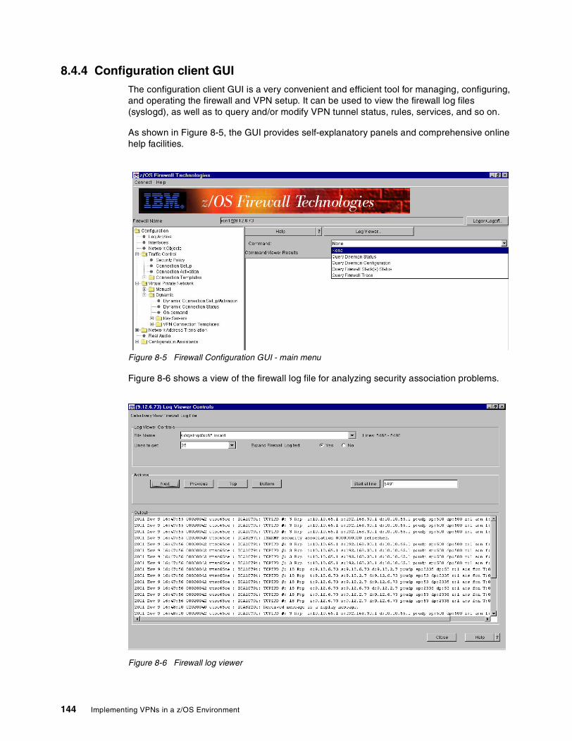
8.4.4 Configuration client GUIThe configuration client GUI is a very convenient and efficient tool for managing, configuring, and operating the firewall and VPN setup. It can be used to view the firewall log files (syslogd), as well as to query and/or modify VPN tunnel status, rules, services, and so on.
As shown in Figure 8-5, the GUI provides self-explanatory panels and comprehensive online help facilities.
Figure 8-5 Firewall Configuration GUI - main menu
Figure 8-6 shows a view of the firewall log file for analyzing security association problems.
Figure 8-6 Firewall log viewer
144 Implementing VPNs in a z/OS Environment
For more details on how to use the GUI, refer to z/OS SecureWay Security Server Firewall Technologies, SC24-5992-01.
8.5 Which tool to useTable 8-1 lists where and how to gather the diagnostic information you’ll need for further problem debugging.
Table 8-1 Selecting the tool
Problem Tools that can help
FWKERN does not start Console Log: Check for error messages, especially ESM-related ones.Check list: Verify the setup; refer to 8.1, “Check list” on page 138.
Tunnel establishing and/or SA problems 1. Syslogdlocal4: Contains a wide range of informational, warning, and error messages logging events such as: successful connection establishment; connection termination; attempts to create Dynamic Connections; security association; Tunnel creation.local0: Provides chronological log records for the entire firewall/VPN configuration, and for setup commands issued by the z/OS firewall administrator (whether issued from the GUI or from a z/OS shell).2. FwtraceProvides the firewall component trace; the trace records are written into fwtrace.data file.Note: This trace could impact system performance, so run it with care.3. ISAKMPDJob output.
Firewall daemon problems 1. The fwdaemon command can be helpful for listing and changing daemon config attributes, querying daemon status, and starting and stopping daemons. For details, see: z/OS SecureWay Security Server Firewall Technologies, SC24-5992-01.2. ISAKMPD Daemon job output.
Chapter 8. VPN operation and problem determination 145
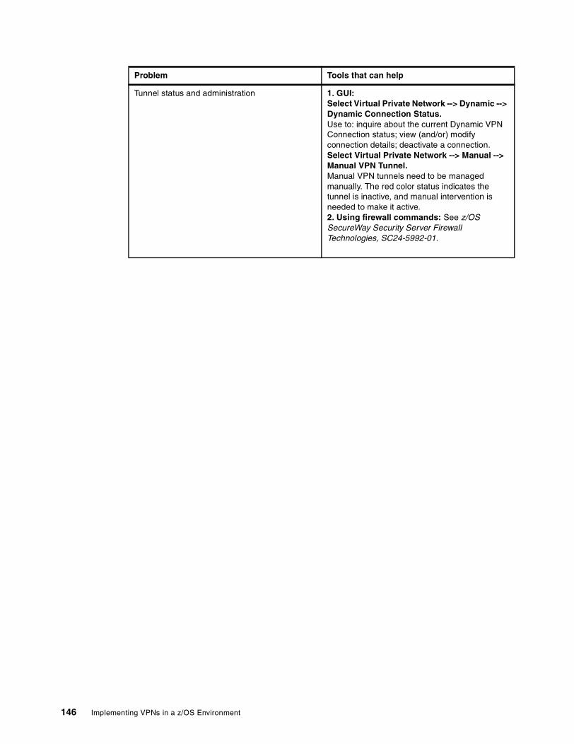
Tunnel status and administration 1. GUI: Select Virtual Private Network --> Dynamic --> Dynamic Connection Status.Use to: inquire about the current Dynamic VPN Connection status; view (and/or) modify connection details; deactivate a connection. Select Virtual Private Network --> Manual --> Manual VPN Tunnel.Manual VPN tunnels need to be managed manually. The red color status indicates the tunnel is inactive, and manual intervention is needed to make it active.2. Using firewall commands: See z/OS SecureWay Security Server Firewall Technologies, SC24-5992-01.
Problem Tools that can help
146 Implementing VPNs in a z/OS Environment

Appendix A. VPN configuration worksheets
This appendix provides worksheets you can use to document the parameters, IP addresses, and protocols you select to satisfy your VPN requirements. We suggest you fill in these worksheets while following the “Data management planning flowchart” on page 32 and the “Key management planning flowchart” on page 43. Once filled in, these worksheets can be used to set up your z/OS VPN configuration and aid in problem determination.
For data and key management information, refer to Chapter 5, “Data management and key management configuration” on page 79.
Detailed information about Network Objects and IPSec/Data Rules, can be found in Chapter 6, “Configuring z/OS Dynamic tunnels - branch office example” on page 95 or Chapter 7, “Configuring z/OS Dynamic tunnels: business partner example” on page 117.
A
© Copyright IBM Corp. 2001 147

A.1 VPN worksheetTable A-1 VPN worksheet
VPN parameter Value
Data policy, proposal, and transform
Dynamic or Manual
Authentication (none, AH, or ESP):
Encapsulation mode (transport or tunnel):
Policy (bronze, silver, or gold):
Encryption (yes or no):
Data transform name:
Data proposal name:
Data policy name:
Key policy, proposal, and transform
Authentication method (Preshared key or RSASignature):
Negotiation (aggressive mode or main mode)
Policy (bronze, silver, or gold):
Key transform name:
Key proposal name:
Key Policy name:
Key servers
Site #1
Key server name:
Auth Id type (IP address, full qualified domainname - FQDN, user@FQDN, or X500_DN)
Auth Id:
Key server IP address (or hostname):
Site #2
Key server name:
Auth Id type (IP address, full qualified domainname - FQDN, user@FQDN, or X500_DN)
Auth Id:
Key server IP address (or hostname):
Key server group name:
On-Demand setup
On-Demand name:
148 Implementing VPNs in a z/OS Environment

A.2 VPN Filter worksheetTable A-2 Network Objects
Table A-3 IPSec/Data Rules
Source IP granularity (anchor or packet):
Destination IP granularity (anchor or packet):
Authentication data
Authentication information name:
For Preshared key only
Shared Key:
For RSA Signatures only
Key ring user ID:
Key ring name:
Certificate Authority name:
RADCERT label:
VPN parameter Value
Network Objects
Object Type (Host, Network, Router, Firewall,interface, or VPN):
Object name:
IP type (IP address, IP subnet, or IP addressrange):
IP address:
Subnet mask (if subnet):
Start IP address (if address range):
Subnet mask (if address range):
Rules
Rule name:
Action (permit, deny, or anchor):
Source port operation (any, equal to, not equal to,greater than, greater than or equal to, less than,less than or equal to):
Source port # Type:
Destination port operation (any, equal to, notequal to, greater than, greater than or equal to,less than, less than or equal to):
Appendix A. VPN configuration worksheets 149
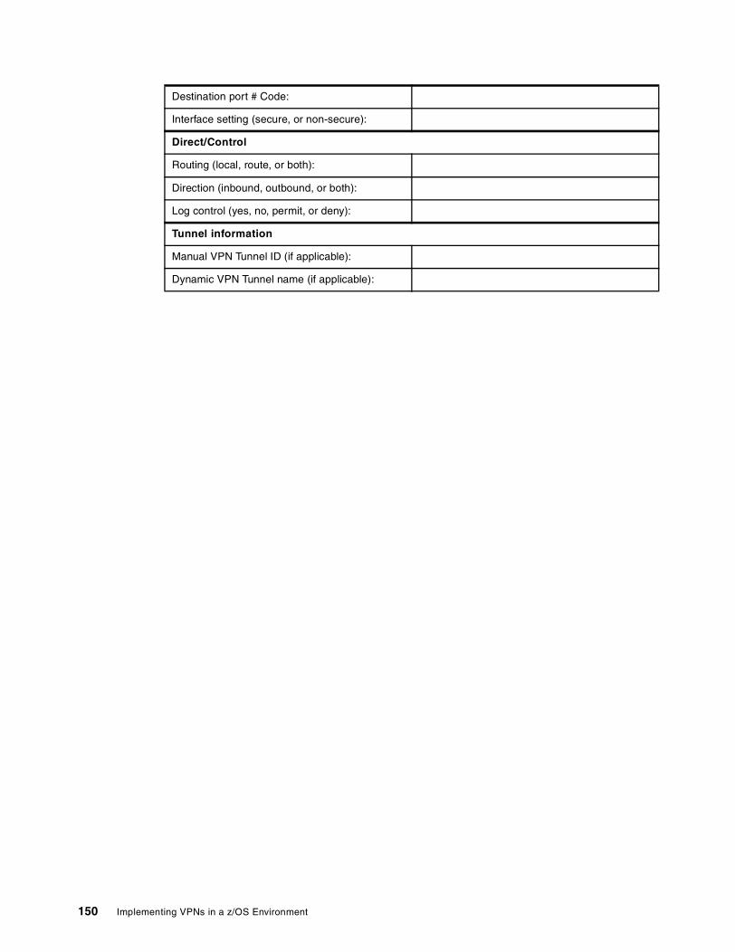
Destination port # Code:
Interface setting (secure, or non-secure):
Direct/Control
Routing (local, route, or both):
Direction (inbound, outbound, or both):
Log control (yes, no, permit, or deny):
Tunnel information
Manual VPN Tunnel ID (if applicable):
Dynamic VPN Tunnel name (if applicable):
150 Implementing VPNs in a z/OS Environment

Appendix B. Windows 2000 VPN configuration
In this appendix, we show how to create a VPN configuration on a Windows 2000 workstation. The Windows 2000 VPN configuration is created as the matching configuration for the remote user in Chapter 7, “Configuring z/OS Dynamic tunnels: business partner example” on page 117.
The Windows 2000 configuration consists of these tasks, which we explain in more detail in following sections:
1. Obtaining certificates (Digital Signature Files) from z/OS using the ftp command
2. Setting up the Microsoft Management Console (MMC)
3. Importing certificates into the Windows 2000 workstation
4. Creating the IP Security policy
5. Testing the VPN connection
The Microsoft Management Console provides certificates and IP Security Policy Management functional windows which you can use to import certificates and configure the VPN connection.
You can monitor the use of Security communication on the ipsecmon window.
B
© Copyright IBM Corp. 2001 151
B.1 Obtaining certificates from z/OSIn this section, we explain how to get the Certificate file from the z/OS member on the dataset to the PC file by using the ftp command. For this example we use the member and dataset name that we referred to in 7.2.8, “Export the Windows 2000 certificate” on page 120.
1. Open the command prompt on the Windows 2000 workstation where you’re going to create a VPN configuration with z/OS. In the following steps, refer to the screen sample shown in Figure B-1 on page 153.
Note: The IP datagram should be reachable between this Windows 2000 workstation and the z/OS Firewall.
2. Type: ftp 192.168.30.1, then press Enter.
3. Type the user ID and press Enter (in this example, we typed in: vpn2).
4. Type the password and press Enter.
5. Type: bin to choose the binary transfer mode, and press Enter.
6. Typ: get 'vpn2.racfca.p12' c:\racfca.p12 and press Enter. You will receive the following messages:
200 Port request OK.
125 Sending data set VPN2.RACFCA.P12
250 Transfer completed successfully.
ftp: 1728 bytes received in 0.15Seconds 11.52Kbytes/sec.
(Notice that the file size varies due to the configuration.)
7. Type: get 'vpn2.client.p12' c:\clientx.p12 and press Enter. You’ll receive the following messages:
200 Port request OK.
125 Sending data set VPN2.CLIENT.P12
250 Transfer completed successfully.
ftp: 2468 bytes received in 0.20Seconds 12.34Kbytes/sec.
(Notice that the file size varies due to the configuration.)
8. Type: bye when the file transfer is completed. The ftp session ends.
152 Implementing VPNs in a z/OS Environment

Figure B-1 Command prompt - ftp
B.2 Setting up the MMC consoleIn this section, we describe how to set up the Microsoft Management Console (MMC). The MMC console will have two Snap-ins added: Certificates, and IP Security Management. The Certificates Snap-in is used to import the certificates that are created by z/OS RACF. The IP Security Management Snap-in is used to configure the VPN connection between the Windows 2000 client and the z/OS server.
1. Click Start -> Run from the Windows 2000 task bar.
2. Enter: mmc in the Open field.
3. Click OK to start the Microsoft Management Console.
4. On the Console 1 window, click Console on the menu bar. On the pull-down menu, click Add/Remove Snap-in....
5. On the Add/Remove Snap-in window, click Add.
6. On the Add Standalone Snap-in window, select Certificates and click Add.
7. On the Certificates Snap-in window, select Computer account and click Next.
8. Select Local computer and click Finish.
9. On the Add Standalone Snap-in window, select IP Security Policy Management and click Add.
10.On the Select Computer window, select Local computer and click Finish.
11.On the Add Standalone Snap-in window, click Close.
12.On the Add/Remove Snap-in window, verify that two snap-ins have been added; Certificates (Local computer) and IP Security Policies on Local Machine. Click OK.
Microsoft Windows 2000 [Version 5.00.2195](C) Copyright 1985-2000 Microsoft Corp.
C:\>ftp 192.168.30.1Connected to 192.168.30.1220-FTPDOE1 IBM FTP CS V1R2 at mike.itso.ibm.com, 22:50:04 on 2001-11-09.220 Connection will close if idle for more than 5 minutes.User (192.168.30.1:(none)): vpn2331 Send password please.Password:230 VPN2 is logged on. Working directory is "/".ftp> bin200 Representation type is Imageftp> get 'vpn2.racfca.p12' c:\racfca.p12200 Port request OK.125 Sending data set VPN2.RACFCA.P12250 Transfer completed successfully.ftp: 1728 bytes received in 0.15Seconds 11.52Kbytes/sec.ftp> get 'vpn2.client.p12' c:\clientx.p12200 Port request OK.125 Sending data set VPN2.CLIENT.P12250 Transfer completed successfully.ftp: 2468 bytes received in 0.20Seconds 12.34Kbytes/sec.ftp> bye221 Quit command received. Goodbye.
Appendix B. Windows 2000 VPN configuration 153

Now you’ve completed the required settings for the MMC console.
B.3 Importing z/OS certificates into Windows 2000In this section, we explain how to import two certificates that are created by z/OS RACF: the Trusted Root CA (Certification Authority) certificate, and the client certificate.
Before installing the client certificate on the Windows 2000 client, Windows 2000 needs to entrust the Trusted Root CA (in this case, z/OS RACF acts as a Trusted Root CA to provide certificates to the clients). After Windows 2000 entrusts the CA, the client certificate can be installed on the Windows 2000 client. This client certificate is used for identity authentication in IKE Phase 1 negotiation.
z/OS RACF creates an individual client certificate for each client, because the client certificate includes the client IP address information. This IP address information is used to verify the required authority on each client to connect to the z/OS Firewall.
Figure B-2 MMC screen
1. On the MMC screen, as shown in Figure B-2, click the plus sign (+) next to Certificates (Local Computer) to show the list of available tasks.
154 Implementing VPNs in a z/OS Environment
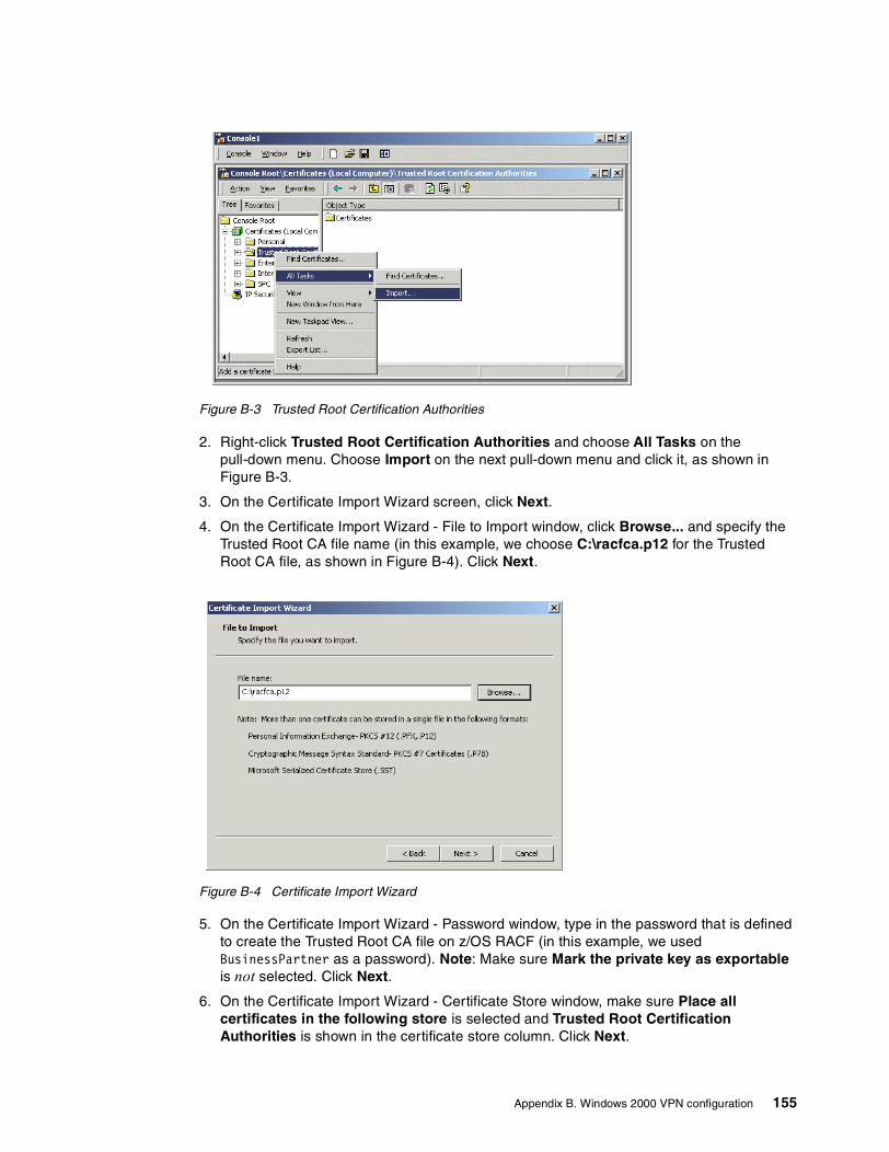
Figure B-3 Trusted Root Certification Authorities
2. Right-click Trusted Root Certification Authorities and choose All Tasks on the pull-down menu. Choose Import on the next pull-down menu and click it, as shown in Figure B-3.
3. On the Certificate Import Wizard screen, click Next.
4. On the Certificate Import Wizard - File to Import window, click Browse... and specify the Trusted Root CA file name (in this example, we choose C:\racfca.p12 for the Trusted Root CA file, as shown in Figure B-4). Click Next.
Figure B-4 Certificate Import Wizard
5. On the Certificate Import Wizard - Password window, type in the password that is defined to create the Trusted Root CA file on z/OS RACF (in this example, we used BusinessPartner as a password). Note: Make sure Mark the private key as exportable is not selected. Click Next.
6. On the Certificate Import Wizard - Certificate Store window, make sure Place all certificates in the following store is selected and Trusted Root Certification Authorities is shown in the certificate store column. Click Next.
Appendix B. Windows 2000 VPN configuration 155
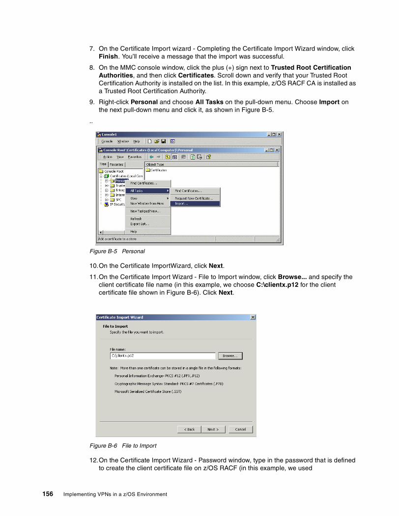
7. On the Certificate Import wizard - Completing the Certificate Import Wizard window, click Finish. You’ll receive a message that the import was successful.
8. On the MMC console window, click the plus (+) sign next to Trusted Root Certification Authorities, and then click Certificates. Scroll down and verify that your Trusted Root Certification Authority is installed on the list. In this example, z/OS RACF CA is installed as a Trusted Root Certification Authority.
9. Right-click Personal and choose All Tasks on the pull-down menu. Choose Import on the next pull-down menu and click it, as shown in Figure B-5.
..
Figure B-5 Personal
10.On the Certificate ImportWizard, click Next.
11.On the Certificate Import Wizard - File to Import window, click Browse... and specify the client certificate file name (in this example, we choose C:\clientx.p12 for the client certificate file shown in Figure B-6). Click Next.
Figure B-6 File to Import
12.On the Certificate Import Wizard - Password window, type in the password that is defined to create the client certificate file on z/OS RACF (in this example, we used
156 Implementing VPNs in a z/OS Environment

BusinessPartner as a password). Note: Make sure Mark the private key as exportable is not selected. Click Next.
13.On the Certificate Import Wizard - Certificate Store window, make sure Place all certificates in the following store is selected and Personal is shown in the certificate store column. Click Next.
14.On the Certificate Import Wizard - Completing the Certificate Import Wizard window, click Finish. You will receive a message that the import was successful.
15.On the MMC console window, click the plus (+) sign next to Personal, and then click Certificates. Scroll down and verify that your client certificate is installed on the list. In this example, Win2000 Client is installed as a client certificate.
B.4 Creating the IP Security policy In the next steps, you will create the IP Security policy on your Windows 2000 workstation for the VPN connection between z/OS and the Windows 2000 client.
1. On the MMC - IP Security Policies on Local Machine window, right-click IP Security Policies on Local Machine. In the pull-down menu, choose Create IP Security Policy and click it, as shown in Figure B-7.
Figure B-7 MMC - IP Security Policies on Local Machine
2. On the IP Security Policy Wizard - Welcome to the IP Security Policy Wizard, click Next.
3. On the IP Security Policy Wizard - IP Security Policy Name window, type in the name for the z/OS VPN connection. In this example, we typed: zOSVPN for the VPN connection name. Type in the description, if required. Click Next.
4. On the IP Security Policy Wizard - Requests for Secure Communication window, clear the Activate the default response rule check box. Click Next.
5. On the IP Security Policy Wizard - Completing the IP Security Policy Wizard, make sure the Edit properties check box is selected. Click Finish.
Appendix B. Windows 2000 VPN configuration 157

Figure B-8 IP Policy Properties window
6. On the IP Policy Properties window (in this example, the zOSVPN Properties window), select the Use Add Wizard check box shown in Figure B-8. Click Add.
7. On the IP Security Wizard - Welcome to the IP Security Policy Wizard window, click Next.
8. On the Security Rule Wizard - Tunnel Endpoint window, select This rule does not specify a tunnel and click Next. This selection means that the z/OS Firewall is the endpoint of the VPN tunnel with Windows 2000, and the VPN tunnel is defined as transport mode.
9. On the Security Rule Wizard - Network Type window, select All network connections. Click Next. In this example, z/OS Firewall and Windows 2000 is connected with Ethernet LAN.
Note: If you want to limit the remote access connection, select Remote Access.
10.On the IP Security Policy Wizard - Authentication Method window, select Use a certificate from this Certificate Authority (CA) and click Browse....
Figure B-9 Select Certificate
158 Implementing VPNs in a z/OS Environment
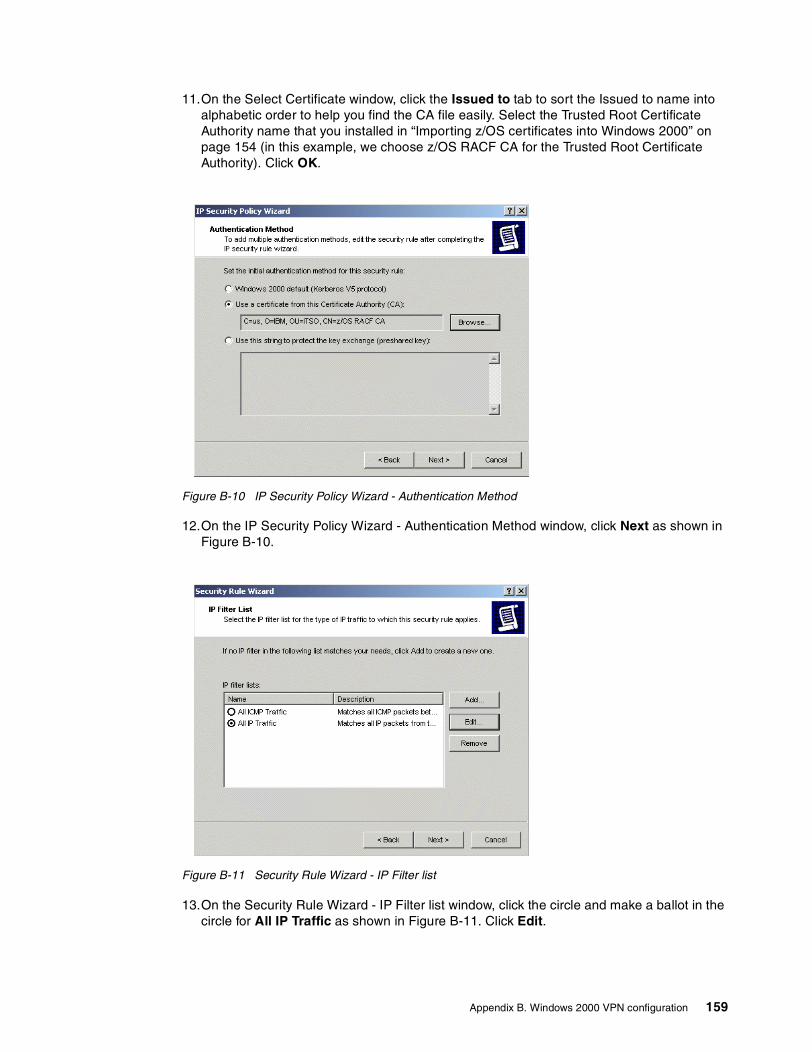
11.On the Select Certificate window, click the Issued to tab to sort the Issued to name into alphabetic order to help you find the CA file easily. Select the Trusted Root Certificate Authority name that you installed in “Importing z/OS certificates into Windows 2000” on page 154 (in this example, we choose z/OS RACF CA for the Trusted Root Certificate Authority). Click OK.
Figure B-10 IP Security Policy Wizard - Authentication Method
12.On the IP Security Policy Wizard - Authentication Method window, click Next as shown in Figure B-10.
Figure B-11 Security Rule Wizard - IP Filter list
13.On the Security Rule Wizard - IP Filter list window, click the circle and make a ballot in the circle for All IP Traffic as shown in Figure B-11. Click Edit.
Appendix B. Windows 2000 VPN configuration 159
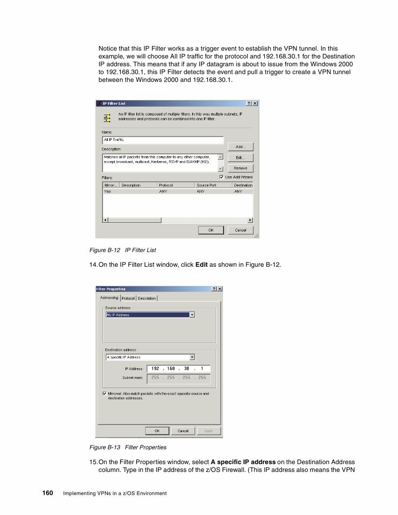
Notice that this IP Filter works as a trigger event to establish the VPN tunnel. In this example, we will choose All IP traffic for the protocol and 192.168.30.1 for the Destination IP address. This means that if any IP datagram is about to issue from the Windows 2000 to 192.168.30.1, this IP Filter detects the event and pull a trigger to create a VPN tunnel between the Windows 2000 and 192.168.30.1.
Figure B-12 IP Filter List
14.On the IP Filter List window, click Edit as shown in Figure B-12.
Figure B-13 Filter Properties
15.On the Filter Properties window, select A specific IP address on the Destination Address column. Type in the IP address of the z/OS Firewall. (This IP address also means the VPN
160 Implementing VPNs in a z/OS Environment
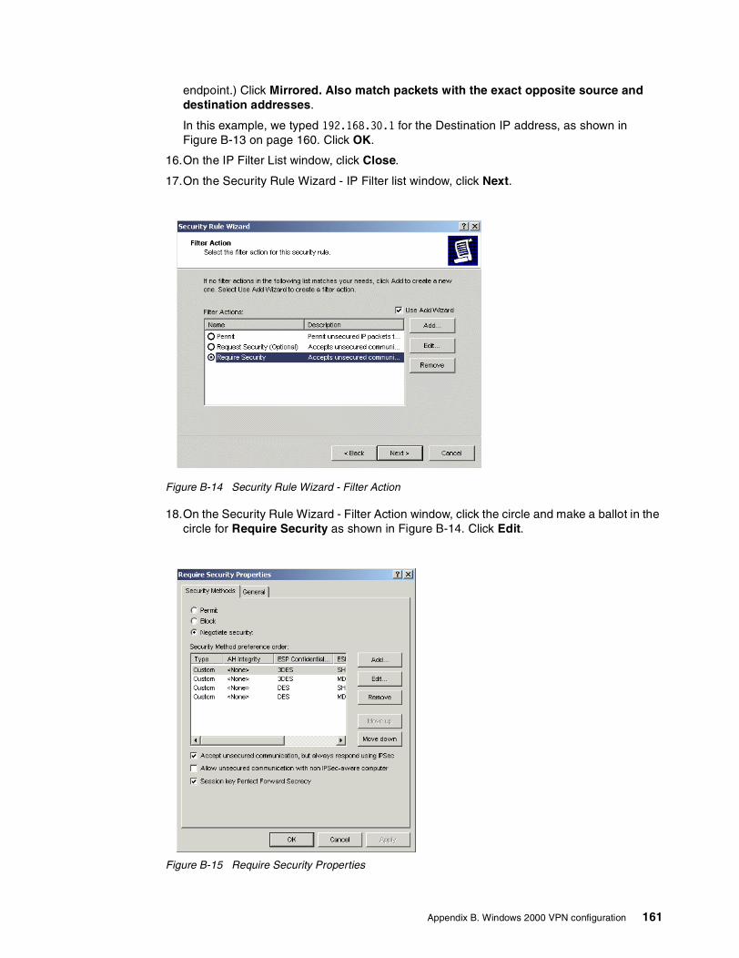
endpoint.) Click Mirrored. Also match packets with the exact opposite source and destination addresses.
In this example, we typed 192.168.30.1 for the Destination IP address, as shown in Figure B-13 on page 160. Click OK.
16.On the IP Filter List window, click Close.
17.On the Security Rule Wizard - IP Filter list window, click Next.
Figure B-14 Security Rule Wizard - Filter Action
18.On the Security Rule Wizard - Filter Action window, click the circle and make a ballot in the circle for Require Security as shown in Figure B-14. Click Edit.
Figure B-15 Require Security Properties
Appendix B. Windows 2000 VPN configuration 161
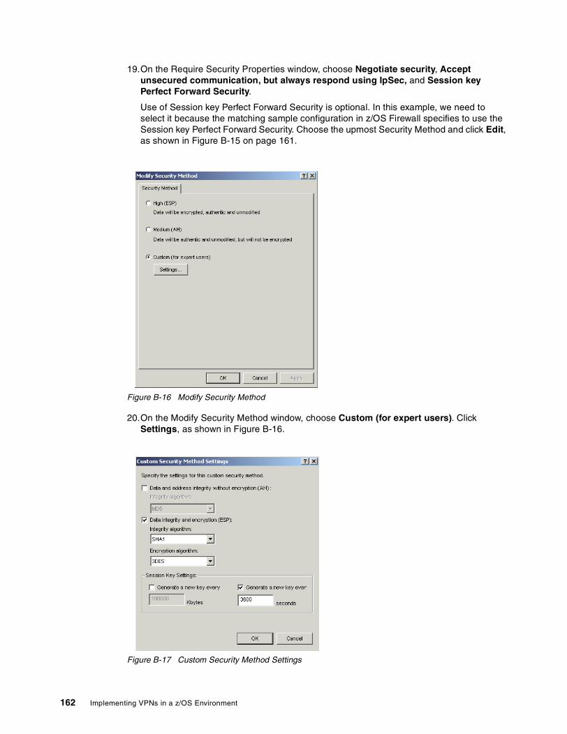
19.On the Require Security Properties window, choose Negotiate security, Accept unsecured communication, but always respond using IpSec, and Session key Perfect Forward Security.
Use of Session key Perfect Forward Security is optional. In this example, we need to select it because the matching sample configuration in z/OS Firewall specifies to use the Session key Perfect Forward Security. Choose the upmost Security Method and click Edit, as shown in Figure B-15 on page 161.
Figure B-16 Modify Security Method
20.On the Modify Security Method window, choose Custom (for expert users). Click Settings, as shown in Figure B-16.
Figure B-17 Custom Security Method Settings
162 Implementing VPNs in a z/OS Environment

21.On the Custom Security Method Settings window, make sure that the Data and address integrity without encryption (AH) checkbox is not selected.
Select Data integrity and encryption (ESP), and select SHA1 for Integrity algorithm. Select 3DES for encryption algorithm. Clear the Generate a new key every Kbytes checkbox. Select the Generate a new key every seconds checkbox and type in 3600 in the seconds column, as shown in Figure B-17 on page 162. This value of 3600 seconds is defined in the example configuration in z/OS Firewall. Click OK.
22.On the Modify Security Method window, click OK.
23.On the Require Security Properties window, click OK.
24.On the Security Rule Wizard - Filter Action windowFilter Action window, click Next.
25.On the Security Rule Wizard - Completing the New Rule Wizard window, click Finish.
Figure B-18 zOSVPN Properties
26.On the zOSVPN Properties window, make sure the All IP Traffic checkbox is checked. Click Close.
Appendix B. Windows 2000 VPN configuration 163
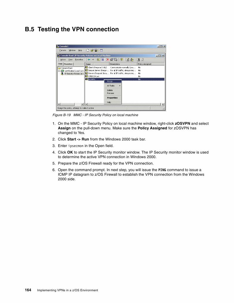
B.5 Testing the VPN connection
Figure B-19 MMC - IP Security Policy on local machine
1. On the MMC - IP Security Policy on local machine window, right-click zOSVPN and select Assign on the pull-down menu. Make sure the Policy Assigned for zOSVPN has changed to Yes.
2. Click Start -> Run from the Windows 2000 task bar.
3. Enter ipsecmon in the Open field.
4. Click OK to start the IP Security monitor window. The IP Security monitor window is used to determine the active VPN connection in Windows 2000.
5. Prepare the z/OS Firewall ready for the VPN connection.
6. Open the command prompt. In next step, you will issue the PING command to issue a ICMP IP datagram to z/OS Firewall to establish the VPN connection from the Windows 2000 side.
164 Implementing VPNs in a z/OS Environment

Figure B-20 Command prompt window - PING command
7. On the Command Prompt window, type in ping 192.168.30.1 as shown in Figure B-20. Notice that the IP address 192.168.30.1 is the IP address of z/OS Firewall. (We use 192.168.30.1, referring to the sample configuration.)
You’ll receive the text message Negotiating IP Security. This message means that IKE Negotiation is on the way to establishing the VPN connection between Windows 2000 and z/OS Firewall. (If necessary, you can issue ping 192.168.30.1 several times until you receive this reply.)
Once you receive the reply from 192.168.30.1, it means the VPN connection is established and all ICMP IP datagrams are encrypted.
Microsoft Windows 2000 [Version 5.00.2195](C) Copyright 1985-2000 Microsoft Corp.
C:\>ping 192.168.30.1
Pinging 192.168.30.1 with 32 bytes of data:
Negotiating IP Security.Negotiating IP Security.Negotiating IP Security.Negotiating IP Security.
Ping statistics for 192.168.30.1: Packets: Sent = 4, Received = 0, Lost = 4 (100% loss),Approximate round trip times in milli-seconds: Minimum = 0ms, Maximum = 0ms, Average = 0ms
C:\>ping 192.168.30.1
Pinging 192.168.30.1 with 32 bytes of data:
Reply from 192.168.30.1: bytes=32 time=10ms TTL=62Reply from 192.168.30.1: bytes=32 time<10ms TTL=62Reply from 192.168.30.1: bytes=32 time<10ms TTL=62
Ping statistics for 192.168.30.1: Packets: Sent = 3, Received = 3, Lost = 0 (0% loss),Approximate round trip times in milli-seconds: Minimum = 0ms, Maximum = 10ms, Average = 3ms
Appendix B. Windows 2000 VPN configuration 165
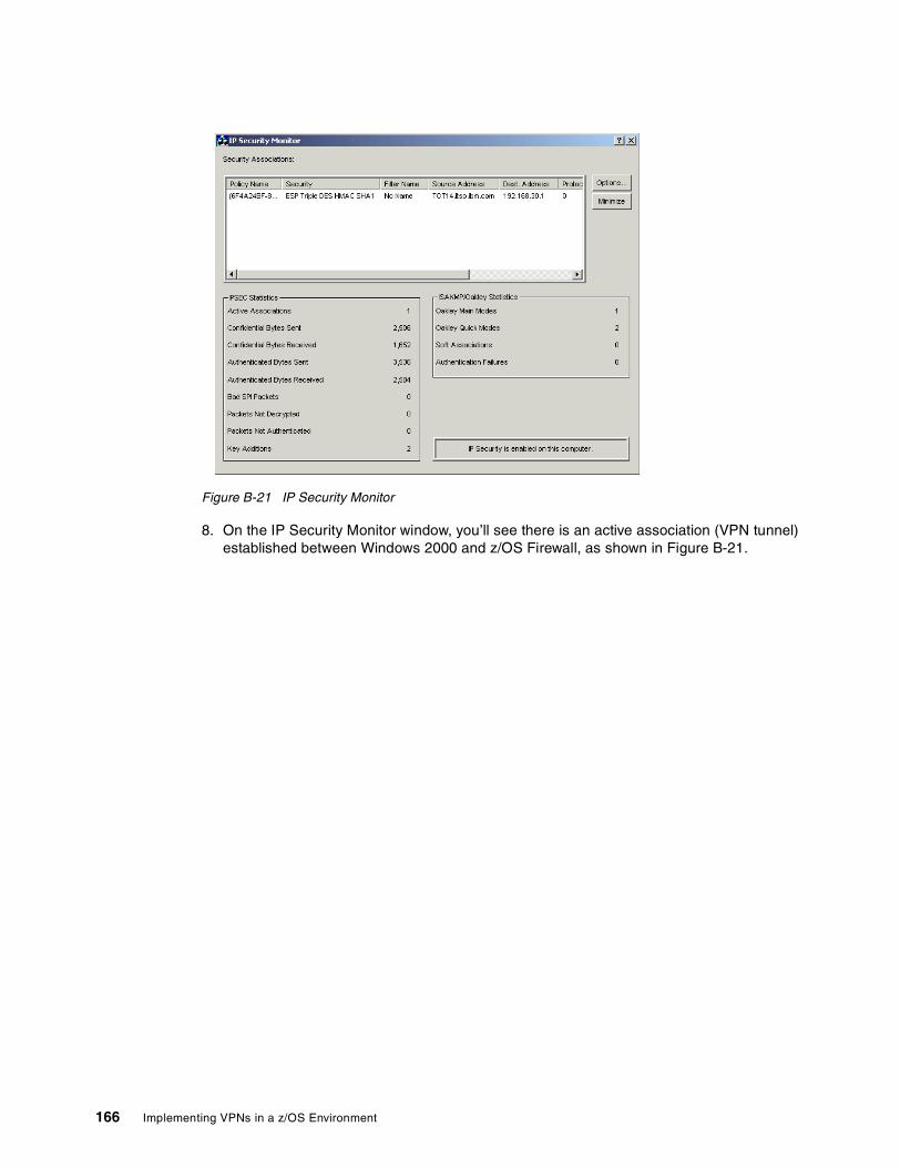
Figure B-21 IP Security Monitor
8. On the IP Security Monitor window, you’ll see there is an active association (VPN tunnel) established between Windows 2000 and z/OS Firewall, as shown in Figure B-21.
166 Implementing VPNs in a z/OS Environment
Related publications
The publications listed in this section are considered particularly suitable for a more detailed discussion of the topics covered in this redbook.
IBM RedbooksFor information on ordering these publications, see “How to get IBM Redbooks” on page 168.
� A Comprehensive Guide to Virtual Private Networks, Volume I: IBM Firewall, Server and Client Solutions, SG24-5201
� A Comprehensive Guide to Virtual Private Networks, Volume II: IBM Nways Router Solutions, SG24-5234
� A Comprehensive Guide to Virtual Private Networks, Volume III: Cross-Platform Key and Policy Management, SG24-5309
� Secure e-business in TCP/IP Networks on OS/390 and z/OS, SG24-5383
Other resourcesThese publications are also relevant as further information sources:
� z/OS SecureWay Security Server Firewall Technologies, SC24-5922
� z/OS Communications Server: IP Configuration Reference, SC31-8776
� z/OS Communications Server: IP Configuration Guide, SC31-8775
� z/OS UNIX System Services Command Reference, SA22-7802
� z/OS SecureWay Security Server RACF Command Language Reference, SA22-7687
Referenced Web sitesThese Web sites are also relevant as further information sources:
� IPSec Working Group of the IETF
http://www.ietf.org/
� RSA Security
http://www.rsasecurity.com/rsalabs/faq/
� Information about WinZip
http://www.winzip.com
� z/OS Firewall Technologies information
http://www.ibm.com/s390/firewall/
© Copyright IBM Corp. 2001 167
How to get IBM RedbooksSearch for additional Redbooks or Redpieces, view, download, or order hardcopy from the Redbooks Web site:
ibm.com/redbooks
Also download additional materials (code samples or diskette/CD-ROM images) from this Redbooks site.
Redpieces are Redbooks in progress; not all Redbooks become Redpieces and sometimes just a few chapters will be published this way. The intent is to get the information out much quicker than the formal publishing process allows.
IBM Redbooks collectionsRedbooks are also available on CD-ROMs. Click the CD-ROMs button on the Redbooks Web site for information about all the CD-ROMs offered, as well as updates and formats.
168 Implementing VPNs in a z/OS Environment

Special notices
References in this publication to IBM products, programs or services do not imply that IBM intends to make these available in all countries in which IBM operates. Any reference to an IBM product, program, or service is not intended to state or imply that only IBM's product, program, or service may be used. Any functionally equivalent program that does not infringe any of IBM's intellectual property rights may be used instead of the IBM product, program or service.
Information in this book was developed in conjunction with use of the equipment specified, and is limited in application to those specific hardware and software products and levels.
IBM may have patents or pending patent applications covering subject matter in this document. The furnishing of this document does not give you any license to these patents. You can send license inquiries, in writing, to the IBM Director of Licensing, IBM Corporation, North Castle Drive, Armonk, NY 10504-1785.
Licensees of this program who wish to have information about it for the purpose of enabling: (i) the exchange of information between independently created programs and other programs (including this one) and (ii) the mutual use of the information which has been exchanged, should contact IBM Corporation, Dept. 600A, Mail Drop 1329, Somers, NY 10589 USA.
Such information may be available, subject to appropriate terms and conditions, including in some cases, payment of a fee.
The information contained in this document has not been submitted to any formal IBM test and is distributed AS IS. The use of this information or the implementation of any of these techniques is a customer responsibility and depends on the customer's ability to evaluate and integrate them into the customer's operational environment. While each item may have been reviewed by IBM for accuracy in a specific situation, there is no guarantee that the same or similar results will be obtained elsewhere. Customers attempting to adapt these techniques to their own environments do so at their own risk.
Any pointers in this publication to external Web sites are provided for convenience only and do not in any manner serve as an endorsement of these Web sites.
The following terms are trademarks of other companies:
C-bus is a trademark of Corollary, Inc. in the United States and/or other countries.
Java and all Java-based trademarks and logos are trademarks or registered trademarks of Sun Microsystems, Inc. in the United States and/or other countries.
Microsoft, Windows, Windows NT, and the Windows logo are trademarks of Microsoft Corporation in the United States and/or other countries.
PC Direct is a trademark of Ziff Communications Company in the United States and/or other countries and is used by IBM Corporation under license.
ActionMedia, LANDesk, MMX, Pentium and ProShare are trademarks of Intel Corporation in the United States and/or other countries.
UNIX is a registered trademark in the United States and other countries licensed exclusively
© Copyright IBM Corp. 2001 169

through The Open Group.
SET, SET Secure Electronic Transaction, and the SET Logo are trademarks owned by SET Secure Electronic Transaction LLC.
Other company, product, and service names may be trademarks or service marks of others.
170 Implementing VPNs in a z/OS Environment

Index
Numerics3DES 173DES_CBC 4, 27, 42
AAF_INET 53AF_UNIX 53Aggressive mode 17–18, 21
comparison 27message 1 21message 2 21message 3 21
AHbenefit 3, 5protocol 3protocol format 3supported methods 30transport mode 3tunnel mode 3
Anchor rule 129, 131Authenticated Header (AH) 2authenticating messages 7Authentication algorithms 26, 42Authentication data 99
Authentication information 99Certificate authority 99Key ring 99
Authentication information 18Authentication protocols 42Authority 54
Bbig integer 6BPXPRMxx 53Branch office connection 46Branch office scenario 96Bronze policy 40, 45Business partner connection 48Business partner scenario 118
CCA certificate 119
export 120CDMF 26Client certificate 119
export 120commands
stop 142Configuration client 79, 144configuration client 69, 71
code 78GUI 77
© Copyright IBM Corp. 2001
configuration server 70CONFIGURED 139CSFSERV 58
DData authentication 123
Authentication information 124Certificate authority 123Key ring 123
data integrity 2Data management 80
AH tansform 80AH transform 80Data policy 85Data proposal 82Dynamic VPN tunnel 87ESP transform 81
data management planning 32data origin authentication 2DES 17DES_CBC 4DES_CBC_4 DES 27DES_CBC_8 41DES_CBC_8 DES 27diagnostic information 145Diffie Hellman 17Diffie-Hellman 17, 20–21, 25
groups 25Digital certificate 118Digital Signature 17Digital Signature (Certificate) 6Dynamic NAT 12Dynamic tunnel 17, 40
comparison 17
EEncapsulated Security Payload (ESP) 2Encryption algorithm 42Encryption algorithms 26ESP
benefit 5protocol 4protocol format 4supported methods 30transport mode 4tunnel mode 4
export 16External Security Manager 139External Security Manager (ESM) 53
Ffilter rules 71FIREWALL 138
171

FORWARDING 138fwadapter 61fwconns 73fwdaemon 61, 69fwfrule 72FWGRP 53fwkern 61FWKERN commands 141
modify 141start 142
fwmigrate 60fwnwobj 72fwservice 72fwstack 61fwtrace command 143
GGold policy 42, 46Group definitions 53GSKKYMAN 74gskkyman 70
HHash algorithms 26HFS filesets 139High risk 42, 46HMAC_MD5 4, 17, 26, 42HMAC_SHA 4, 17, 26, 41–42
IICA1079i 140ICA8298i 140ICAPIKED 140iconv 60ICSF/MVS 57Identity information 18IETF standards 17IKE 6, 16, 44
Phase 1 SA negotiation 7Phase 2 SA negotiation 8
IKE negotiation 17IKE Phase 1 6
Main mode 18negotiation 17supported methods 29
IKE Phase 2 4, 7message 1 22message 2 23message 3 23negotiation 18, 22
import 16Initiator 7, 18, 23initiator 19Internet Key Exchange (IKE) 2, 6IP checksum 12IP datagram 3IP header 3–4IP Security (IPSec) 1
IP Security Policy 157IPCONFIG 138IPSec 35
architecture 2RFCs support 28
ISAKMP 6, 16, 56, 68, 127standard 17support 17
ISAKMPD 120, 140
Jjob logs 143
Kkey exchange 40key expiration 7Key management 88
Key policy 92Key proposal 90Key transform 89
Key management planning 43Key ring 119Key server 96, 121Key server group 98, 122KEYED_MD5 26keying material 6, 18
LL2TP
Compulsory tunnel 10IP Address Management 11tunnel modes 9Voluntary tunnel 9
L2TP Access Concentrator (LAC) 9L2TP Network Server (LNS) 9L2TP tunnel 8LAC 9–10Layer 2 Tunneling Protocol (L2TP) 8LNS 9–10Log files 142logging 140logical tunnel 8Low risk 40, 45
MMain mode 18, 22
comparison 27message 1 19message 2 19message 3 20message 4 20message 5 20message 6 20
main mode 17Manual tunnel 40
comparison 17configuration client GUI 16description 16
172 Implementing VPNs in a z/OS Environment

fwtunnl command 16master secret 6MAXFILEPROC 52MAXLEN 58MAXPROCSYS 52MAXPROCUSER 52MAXSOCKETS 53MAXTHREAD 53MAXTHREADTASKS 53Medium risk 41, 45MMC console 153mutable fields 3
NNAT 34
considerations 35NAT conflict
AH protocol 35ESP transport mode 37
NAT variations 12Network Address Port Translation (NAPT) 13Network Address Translation (NAT) 12nonce 20, 23
OOCEP 67OCSF 64On-Demand 124
setup 100Open Cryptographic Enhanced Plug-ins (OCEP) 56Open Cryptographic Services Facility (OCSF) 56
PPerfect Forward Secrecy (PFS) 25Perfect Forward Security (PFS) 22Point-to-Point protocol (PPP) 8PPP connection 10Pre- Shared Key 17Pre-shared key 23Pre-shared key encryption 6Pre-Shared Keys 17private key 24processing power 40, 42profile 138proposal priority 7Pseudo-random function 18pseudo-random function (prf) 17public key 24Public Key encryption 6
QQuick Mode 7
RRACDCERT 70, 73, 123RACF 45, 53, 70, 73, 118, 140RACF command
RACDCERT 119RACF messages 143Redbooks Web site 168
Contact us viiiRemote user connection 49replay protection 2Request For Comments (RFC) 1Responder 7, 18, 23responder 19Revised public key encryption 6RFC 1631 12RFC 2407 17RFC 2408 17RFC 2409 17RFC 2661 8Risk assessment 40RSA algorithm 24RSA Digital Signature 45RSA Signature 21RSA signature
authentication 20RSA Signature Authentication 18
SSA combination 5
benefits 5SA negotiation 6SA proposal 7–8, 17–18, 21Secure Sockets Layer (SSL) 70Security Association (SA)
description 2security policies 34security policy 46security zones 34Server certificate 120Session Key Lifetime Range 26Session Maximum Key Lifetime 25Session Maximum Size Limit 26Session Size Limit Range 26SET OMVS 62SETOMVS 62Silver policy 41, 45simplex 7–8SKEYID 18, 23, 25started tasks 138Static NAT 12syslogd 63, 143
TTCP checksum 12TCP/IP commands 143TCPIP definitions 58Topology
cascading tunnels 34nested tunnels 35single tunnel 34
Transport mode 2, 40Triple DES 27Tunnel mode 2, 27, 40
Index 173

UUDP packet 8
VVirtual Private Network (VPN) 1VPN
connection test 164description 1problem determination 138setup Verification 139
VPN filter 101, 125connections 113, 133Data rule 129Data rules 107Data service 111, 131Dynamic connection 112, 132IPSec rules 104, 127IPSec service 110, 130Network objects 101, 125
WWindows 2000
Certificate 152import 154setup 151
WITHLABEL 123
174 Implementing VPNs in a z/OS Environment

(0.2”spine)0.17”<->
0.473”90<->
249 pages
Implem
enting VPNs in a z/OS Environment
Implem
enting VPNs in a z/OS Environment


®
SG24-6530-00 ISBN 0738424331
INTERNATIONAL TECHNICALSUPPORTORGANIZATION
BUILDING TECHNICAL INFORMATION BASED ON PRACTICAL EXPERIENCE
IBM Redbooks are developed by the IBM International Technical Support Organization. Experts from IBM, Customers and Partners from around the world create timely technical information based on realistic scenarios. Specific recommendations are provided to help you implement IT solutions more effectively in your environment.
For more information:ibm.com/redbooks
Implementing VPNs in a z/OS EnvironmentPlanning and implementation guidance
Realistic examples and scenarios
Troubleshooting tips for common VPN problems
This IBM Redbook covers the planning and implementation of Virtual Private Networks (VPN) in a z/OS environment. It discusses VPN terminology, supported topologies, and functionality provided by the z/OS Firewall Technologies.
The book offers guidance and recommendations for planning by utilizing flowcharts and walkthroughs of the most common VPN scenarios, and provides information that focuses on the definitions needed to configuring VPN solutions, using the configuration client GUI. Helpful information for verifying and monitoring your VPN installation is also included.
This redbook is intended for systems programmers, network planners, and systems engineers who will plan and install VPNs using z/OS Firewall Technologies. A good background in UNIX System Services and TCP/IP for z/OS, network planning, and network security is assumed.
Back cover