from uml diagrams to behavioural source code - cwipaulk/thesesmastersoftwareengineering/... · from...
TRANSCRIPT

From UML diagrams to behavioural source code
Sabrina L. JimUniversiteit van Amsterdam
September 7, 2006
Centrum voor Wiskunde en Informatica
Thesis and internship supervisor :
prof. dr. P. Klint
Availability: public domain

2

Contents
Summary 5
Preface 7
Acknowledgement . . . . . . . . . . . . . . . . . . . . . . . . . . . . . . . . . . . . . . . . . . . . . 7
1 Problem Description 9
1.1 The problem . . . . . . . . . . . . . . . . . . . . . . . . . . . . . . . . . . . . . . . . . . . . . 10
1.2 The research question . . . . . . . . . . . . . . . . . . . . . . . . . . . . . . . . . . . . . . . . 11
1.3 Research plan . . . . . . . . . . . . . . . . . . . . . . . . . . . . . . . . . . . . . . . . . . . . . 12
2 Background and Context 15
2.1 Model Driven Architecture . . . . . . . . . . . . . . . . . . . . . . . . . . . . . . . . . . . . . 15
2.2 Unified Modelling Language . . . . . . . . . . . . . . . . . . . . . . . . . . . . . . . . . . . . . 16
2.3 XML Metadata Interchange . . . . . . . . . . . . . . . . . . . . . . . . . . . . . . . . . . . . . 17
2.4 Mapping between UML behaviour diagrams and XMI . . . . . . . . . . . . . . . . . . . . . . 19
2.5 Implementation languages . . . . . . . . . . . . . . . . . . . . . . . . . . . . . . . . . . . . . . 24
2.6 Template-based generator . . . . . . . . . . . . . . . . . . . . . . . . . . . . . . . . . . . . . . 27
3 Plan Execution 31
3.1 Selecting UML diagrams and UML tool . . . . . . . . . . . . . . . . . . . . . . . . . . . . . . 31
3.2 Making a UML profile for more expressiveness . . . . . . . . . . . . . . . . . . . . . . . . . . 35
3.3 Transforming XMI into Interformat . . . . . . . . . . . . . . . . . . . . . . . . . . . . . . . . . 41
3.4 Resolving the stereotypes . . . . . . . . . . . . . . . . . . . . . . . . . . . . . . . . . . . . . . 45
3.5 Merging behaviour diagrams with a class diagram . . . . . . . . . . . . . . . . . . . . . . . . . 46
3.6 Transforming Interformat into BAST . . . . . . . . . . . . . . . . . . . . . . . . . . . . . . . . 51
3.7 Generating Java source code . . . . . . . . . . . . . . . . . . . . . . . . . . . . . . . . . . . . . 53
3.8 Verifying generated source code with the Java test case system . . . . . . . . . . . . . . . . . 55
3.9 An overview of the transformers and generators in this project . . . . . . . . . . . . . . . . . 56
3

4 Results 59
4.1 How are behaviour diagrams saved in XMI, and is that representation practical for codegeneration? . . . . . . . . . . . . . . . . . . . . . . . . . . . . . . . . . . . . . . . . . . . . . . 59
4.2 Which behaviour diagrams are suited for generating behavioural source code? . . . . . . . . . 60
4.3 How can we constrain the modelling possibilities and simultaneously increase the expressive-ness in behaviour diagrams? . . . . . . . . . . . . . . . . . . . . . . . . . . . . . . . . . . . . . 61
4.4 How can we make the mapping between structure and behaviour diagrams clear? . . . . . . . 62
5 Evaluation 63
5.1 Abstraction level in the diagrams . . . . . . . . . . . . . . . . . . . . . . . . . . . . . . . . . . 63
5.2 The XMI and Interformat . . . . . . . . . . . . . . . . . . . . . . . . . . . . . . . . . . . . . . 63
5.3 Generating control constructs . . . . . . . . . . . . . . . . . . . . . . . . . . . . . . . . . . . . 64
5.4 Checking the diagrams . . . . . . . . . . . . . . . . . . . . . . . . . . . . . . . . . . . . . . . . 64
Bibliography 65
A State of the art: XMI 67
A.1 Errors in the XMI specification . . . . . . . . . . . . . . . . . . . . . . . . . . . . . . . . . . . 67
B Architecture of Interformat and XMI 69
4

Summary
Code generation from UML diagrams gains much attention lately in software engineering, because it hasmany benefits including the effort that is put into modelling is (fully) reused and generation of code is lesserror prone than writing code manually.
A framework that uses code generation is Model-Driven Architecture (MDA). The aim of MDA is to preservethe IT investments of companies despite the constant and rapid evolutions of platforms. Models in MDA arethe key artefacts in all phases of development and are mostly expressed with Unified Modelling Language(UML). The latter is represented in XML Metadata Interchange (XMI).
MDA has a three abstraction layer approach, namely Platform Independent Model (PIM), Platform SpecificModel (PSM), and code level. Functionality and behaviour of a system is saved in a PIM. After modelling,the PIM is transformed into one or more PSM automatically. Source code is generated from these PSMs.
Generation of behavioural source code can be done by means of UML behaviour diagrams. However, UMLtools do not support the generation of source code from these diagrams, because (1) there is no one to onemapping between behaviour descriptions and the source code, (2) behaviour does not always have to appearin source code as explicit statements, (3) behaviour diagram can be implemented in different ways, and (4)the mapping between structure and behaviour diagrams is not always clear.
Due to all these problems, tools only generate the structure of the modelled system. MDA allows engineersto add source code to the generated code. The drawbacks of modifying the generated code are that themanually added code will be lost when engineers regenerate the source code from the models and errors canbe introduced.
The goal in this project is to generate source code that also contains the structural as well as the behaviouralaspect. As a result, modification to the generated source code is not needed. Note that we focus on thelowest generation step of MDA, which is from PSM to source code. The research question of this project isas follows:
How can behavioural code be generated using both structure and behaviour diagrams, despite the fact thatUML does not provide a clear mapping between these types of diagrams?
In order to answer this question, we performed the following steps. (1) We selected a few UML diagramsand a UML tool. (2) We have built a test case system in order to verify the generated code in the end. (3)We investigated how we could extend/limit the modelling principles of UML. (4) We have built a generatorthat gives a tree format as output, which is used as input by a template-based generator (developed byArnoldus). (5) The template-based generator generates source code, which we verify with our test casesystem (developed in step 2).
While we were executing these steps, we selected the state and the activity diagrams to model the behaviourand the class diagram to define the structure. Both behaviour diagrams can be modelled at the attributelevel, which makes the gap between model and source code smaller. We concluded that these diagramscontain enough information for the generation of behavioural source code. The diagrams are modelled in aUML tool, called Poseidon.
5

While we were investigating the XMI that is generated by Poseidon, we discovered that XMI is very tool-specific, it contains references to other documents which are generated by other UML tools, it is very verbose,and it can expand to megabytes that lead to memory errors. That is why we transformed the XMI intoanother format (Interformat), which we defined by ourselves.
We use a UML profile to extend/limit UML that contains stereotypes and restrictions. While the stereo-types give us the possibility to define a behaviour in a concise way, the restrictions eliminate ambiguousinterpretations of the behaviour diagrams.
In order to make a clear mapping between the structure diagram and the selected behaviour diagrams, wedefined a rule in our UML profile that is defined as follows: the diagram must be saved at the same level andhave the same name as the related UML element. As a result, the modelled behaviour will be generated atthe right place in the source code.
Modifications in the generated source code are not needed any more, because it contains structure as wellas behaviour aspects. As a result the source code is well-formed, it has the same meaning as the modelledbehaviour, and it has the same architecture as code that is developed manually.
6
Preface
Although we are almost always working with computers, it is always about people. We create programs tosimplify our jobs or make work process quicker. We try to use several techniques to make better programs.However, much programs that we make nowadays still contain errors. We are not able to remain the qualityin each program that we make.
Many scientists are developing new techniques to ensure the quality of software. Sometimes a techniqueseems to be a real promise. As a consequence, many companies and engineers are running after it withoutthinking whether it is a real promise or not.
We think that new techniques do not always bring something new. Sometimes it is actually an old techniquethat is given a new face-lift with new buzz words. However, old techniques in another context can give newinsights in old problems. We should investigate these new techniques carefully. Model Driven Architecture(MDA) is an example of a popular ‘new’ technique.
This thesis is the result of a master project of the one year Master program Software Engineering at theUniversity of Amsterdam. This master project is about code generation from diagrams without the need tomodify the generated source code.
The master project took us at least four months work. We tried to combine the techniques that we havelearned during the lectures and practice. Many lessons are learned in this short time, including the following:
‘It does not matter how slowly you go so long as you do not stop.’‘Learning without thought is labour lost; thought without learning is perilous.’ - Confucius -
Sabrina Jim
Acknowledgement
First of all, I want to thank everybody who helped me somehow or other during this project, but are notmentioned below.
I want to thank Paul Klint for giving me the possibility to do my master project at the CWI and thesupervision during this project. Jurgen Vinju and Mark van den Brand for the inspirations and discussionsincluding transformations. Machiel Bruntink for helping me when I practice my biggest feature in ASF+SDFof creating cycles. My roommates for the fun, jokes, and support.
Bas, I want to thank you for everything, because you know more than anybody else what situations I hadto face. I also want to thank my family: father, mother, and my sisters. I have learned how to deal withstress because of you.
Mrs. De Jong (Dutch): graag wil ik u bedanken voor alle steun die u mij gaf. Ook voor alle gesprekken dieover van alles gaan. Het maakt het werk in het weekend leuker en lichter.
7

8

Chapter 1
Problem Description
Introduction
It is always about quality in the software industry. We are looking for ways to improve quality. As aconsequence the development productivity decreases, because we have to take more time to check the sourcecode that we wrote. As a result we are looking for ways to develop techniques in order to improve qualityas well as increase development productivity. The effort that has been invested by engineers resulted incompilers, parsers, high-level languages, domain-specific languages, etcetera.
Engineers use various techniques to control the quality. An example of a technique is UML (Unified ModellingLanguage). UML is a general-purpose modelling language and is seen as the de facto standard. Engineersmake UML diagrams of complex systems. A diagram is a simplification of the reality. Because of thesimplification, engineers can understand systems that they are developing. The assumption is that betterunderstanding leads to a system with higher quality.
Transformation and generation as a part of the development process
A known technique which focuses on the behaviour of a system is Model-Driven Architecture that is abbre-viated as ‘MDA’. Models in MDA are the key artefacts in all phases of development. The aim of MDA is topreserve the IT investments of companies despite the constant and rapid evolutions of platforms. Note thatwe use diagram and model interchangeably.
Functionality and behaviour of a system is saved in a Platform Independent Model (PIM). This model shouldbe transformed in one or more Platform Specific Models (PSM) automatically. The models are mostlyexpressed with UML and are saved in a format that is based on XML (eXtensible Markup Language), calledXMI (XML Metadata Interchange).
XMI is an OMG (Object Management Group) standard that is particularly developed to save UML diagramsin XML format. In spite of the OMG standard, many UML tools save the supported diagrams in their ownXML-based format. The XML-based format contains data like classes, source code documentation, diagramlay-out, and tool-specific settings. As a consequence transformers and generators also have to use a tool-specific XMI as input for their transformation or generation process.
It is very difficult to generate behavioural source code automatically, because there are many ways to expressa behaviour in a behaviour diagram. As a result, developing a generator that supports all possibilities is notpractical to implement. Note that if we mention behavioural source code we mean source code that needs nofurther modification or extension, is well-formed, and can be compiled by a compiler. The compiled sourcecode may contain run-time errors, but we will try to generate source code that contains no errors.
9

10 1.1. The problem
Although MDA promises a lot, it does not describe which diagrams engineers need to use in order to modelfunctionality and behaviour. Of course, it depends on a specific situation which diagrams an engineer needs.However, we think that there is a subset of diagrams which can be applied to most systems, because someaspects are common. For example, every system has actions. As a result the activity diagram is alwaysapplicable.
Tools for generating source code
Many UML tools and all MDA tools support code generation from UML diagrams. A few examples of thosetools are OptimalJ (Compuware), Enterprise Architect (Sparx Systems), Poseidon (Gentleware), ArgoUML(open source1), and MagicDraw (No Magic).
However, most of them are not able to generate behavioural source code, because they only generate sourcecode from a class diagram. That is why those tools also allow engineers to modify the generated code. Sourcecode which is added by hand will be lost if those engineers generate the source code again, or they have todo a lot of copying and pasting, which is very error prone.
Only a few tools like Fujaba2 and MetaEdit3 [LKT04] succeed in generating behavioural source code thatis also executable. Fujaba uses UML in combination with a domain-specific language for embedded real-time systems. MetaEdit gain expressiveness by means of metamodelling (defining a new domain-specificlanguage). As a result, engineers do not have to modify the generated code.
1.1 The problem
The questions that rise are ‘Why do UML or MDA tools not generate behavioural source code? We alreadycan generate static code from a class diagram. So, why can we not generate semantics from UML be-haviour diagrams also?’ We cannot give a precise answer to these questions, but we think that the followingconsiderations help to get some insight in this matter.
A class diagram is easy to understand for an engineer. It gives an overview of classes, which have relationswith each other. There is a one to one mapping between the diagram (modelled on the PSM level) andsource code. However, a class diagram does not contain information about the behaviour of the system. Asa consequence the generated source code does not contain behavioural source code either.
So, if engineers want to generate behavioural source code, they have to use diagrams that do contain be-haviour information. UML has a set of diagrams to model the behaviour of a system: e.g. activity diagram,use case, state (machine) diagram, sequence diagram, communication diagram, interaction overview diagram,and timing diagram.
Unlike the class diagram, these types of diagrams are more difficult to draw. The reasons are as follows:
1. There is no one to one mapping between these behaviour diagrams and the source code (becausebehaviour can cover many source code statements, which appear at different places in a class orclasses),
2. behaviour does not always have to appear in source code as explicit statements,
3. behaviour diagram can be implemented in different ways, and
4. the mapping between structure and behaviour diagrams is not always clear (which makes automaticcode generation including behavioural aspects more difficult).
1ArgoUML - http://argouml.tigris.org/2University of Paderborn, Software Engineering Group - http://www.fujaba.de/3MetaCase - http://www.metacase.com/

Chapter 1. Problem Description 11
For these reasons behaviour diagrams are not frequently supported for code generation in UML tools. As aresult, behaviour diagrams are only used for communication purposes.
1.2 The research question
The aim of this project is to generate behavioural source code from UML diagrams. We formulated a researchquestion and some subquestions in order to solve those problems.
The research question of this project is as follows:
‘How can behavioural code be generated using both structure and behaviour diagrams, despite the fact thatUML does not provide a clear mapping between these types of diagrams?’
In order to answer this research question we formulate some subquestions:
• ‘How are behaviour diagrams saved in XMI, and is that representation practical for code generation?’For code generation we need to know how behaviour diagrams are saved in the XMI format, becausethen we gain insight in the available data which we can use for the generation process. We will onlyinvestigate some selected behaviour diagrams (see Section 3.1.1 for the selected diagrams).
This question does not have a clear mapping with the problems that are mentioned in the previoussection.
• ‘Which behaviour diagrams are suited for generating behavioural source code?’We do not need to use all behaviour diagrams of UML to specify a particular behaviour. If we use alldiagrams, the generation process will be very complex, because then the generator will have to take alldiagrams into account and analyse them before it can generate source code. To keep the generation ofbehavioural source code simple, we will select a few diagrams.
This question maps with the following problems: there is no one to one mapping between behaviourdescriptions and the source code and behaviour does not always have to appear in source code explicitas statements.
• ‘How can we constrain the modelling possibilities and simultaneously increase the expressiveness inbehaviour diagrams?’UML is a open and abstract language. Every diagram can be used independently and adding new ‘arte-facts’ (elements that do not belong to the core set) is also possible. There are no strict modelling rules.Because of that, a generator must take all possibilities into account. For example, a if-then-statement
can be modelled in at least three different ways in an activity diagram. By constraining the way ofmodelling, the generator does not have to take the exceptional situations into account. As a result, wecan generate source code in a much more effective way. It also makes the behaviour diagrams easierto understand and we try to make a one to one mapping with the source code.
This question maps with the following problems: there is no one to one mapping between behaviourdescriptions and the source code, behaviour does not always have to appear in source code explicit asstatements, and a behaviour diagram can be implemented in different ways.
• ‘How can we make the mapping between structure and behaviour diagrams clear?’As mentioned, every diagram can be used independently. There are no rules about when a diagramshould be used to describe a feature or an element. For example, it is possible to use all diagramsto describe a use case. Code generation in this situation is only possible if it is done manually. Byconstraining the diagrams a generator knows what next step it must take in order to produce sourcecode.
This question maps with the following problem: ‘the mapping between structure and behaviour diagramsis not always clear’.

12 1.3. Research plan
The models that we make in this project are modelled at the level of PSM. We investigate the generationfrom PSM to source code and we will discuss the tool(s) that we have developed.
1.2.1 The benefits of solving the problem
Answering the research questions has several benefits.
First, the effort that is put into modelling at the PSM level is (fully) reused. The behaviour diagrams areused for communication purposes, but now they are is also used as input data in order to generate sourcecode.
Second, fully automatic code generation is less error prone than the traditional way. The source code isgenerated in a consistent way that needs no further modification or extension. As a result, there will be nosyntax errors or faults caused by copying and pasting.
Third, fully automatic code generation decreases development time. It is possible to buy or to develop anown generator. In case of the latter, developing a generator can take months. Although the generated codecan be developed in the same development time as the generator itself, the pay off of using a generator iswhen engineers are reusing it for another system. Generating source code for another system is done in justa few seconds, without developing a new generator again.
Fourth, design documentation is always up to date, because every change to the system will also be madein the structure and behaviour diagrams.
Last, it creates a single point of definition.
1.3 Research plan
The steps that we will take in this project are shown in Figure 1.1.
First, we select a UML tool and (structure and behaviour) diagrams that we use for modelling. Second,we develop a Java system manually to validate the generated system in the end. Third, we extend or limitUML, because UML is not expressive enough. We also make a model of the Java system with the selecteddiagrams. Fourth, we make a generator that generates an input (a BAST) for a template-based generator.Fifth, the template-based generator takes the BAST and generates a system. Last, we validate the generatedsystem with the one that is developed manually. This last step will be done by ourselves.
First step We will select a UML tool which supports structure as well as behaviour diagrams and saves itsdiagrams in XMI. We need a UML tool that supports behaviour diagrams, because those are used to expressbehavioural source code. All UML tools support at least the use of a class diagram, which is a structurediagram. Because of that, we also use that structure diagram in the generation process. As a result, we areable to relate a behaviour to a specific class or method.
Second step We develop a Java test case system manually, which we will use as a test case to validatethe system that we will generate. We have formulated a few requirements to determine whether the codethat we are going to generate is good or not. The requirements are defined as follows.
1. The code must be well-formed.Like manually developed code, the generated source code has to be well-formed, because otherwise wecannot compile it (to byte code).
2. The generated code must be semantically the same as the modelled behaviour.It is obvious that the modelled behaviour in the diagrams must also appear in the generated code,

Chapter 1. Problem Description 13
because that is what we want to generate in this project. However, we do not mean that the syntax ofthe generated code has to be exactly the same as the manually developed code.
3. The architecture of the generated code should be the same as the code that is developed manually.By defining this requirement, we reuse the effort that has been given while defining the architecture.With architecture we mean the structure and relations of classes. As a result of this requirement, thedefined behaviour will generated in its related class.
Third step We extend or limit UML, because it is not expressive enough for generating behavioural sourcecode. There are known techniques that are frequently used for this activity, namely metamodelling and usinga UML profile. In this step we will decide which technique we will use.
We also make diagrams of the Java system in this step. These diagrams will be used as input for ourgenerator that we will develop in the next step. In the end, the generator generates a Java system with thesame behaviour as modelled in the diagrams.
Fourth step We develop a generator that takes UML diagrams as input and generates Java code. Whilegenerating source code, the generator merges the behaviour diagrams into one structure diagram. Whenmerging is finished, the generator generates a BAST (Balance Abstract Syntax Tree) as output. That formatis used by a template-based generator.
Fifth step We use a template-based generator developed by Arnoldus [Arn06]. The generator takes thegenerated BAST of the previous step as input and generates Java source code.
Last step We compare the generated source code with the manually developed one, which behavioursshould be the same. This step will be done manually, because only then we can say that the generation ofbehaviour source code has been successfull.
Note that step two is discussed in Section 3.8.
Figure 1.1: An abstract visualisation of plan of project

14 1.3. Research plan

Chapter 2
Background and Context
Introduction
In this chapter we will discuss the techniques that we use. Those are Model Driven Architecture (MDA),Unified Modelling language (UML), XML Metadata Interchange (XMI), Extensible Stylesheet LanguageTransformations (XSLT), ASF+SDF, and Balance Abstract Syntax Tree (BAST).
2.1 Model Driven Architecture
The aim of MDA is to preserve the IT investments of companies despite the constant and rapid evolutionof platforms (e.g. a specific programming language). MDA tries to capture investments in one PlatformIndependent Model (PIM) which should not be affected by major or minor changes in platforms. As thename of MDA already says, models are the key artefacts in all phases of development.
An MDA specification consists of a platform independent base UML model (PIM), plus one or more PlatformSpecific Models (PSM) and interface definition sets, each describing how the base model is implemented ona different platform. It focuses primarily on the functionality and behaviour of a distributed applicationor system (the PIM), not the technology in which it will be implemented. PSM takes the responsibility ofdescribing the functionality and behaviour in one or more particular technologies.
Figure 2.1: MDA hierarchy
By separating the functionality and behaviour from technologies, it is not necessary to model the system’sfunctionality and behaviour again each time a new technology passes by. The PIM will be transformed byone or more transformers to PSMs. The lowest level of MDA is the source code level. The hierarchy of MDA
15

16 2.2. Unified Modelling Language
is shown in Figure 2.1.
To be able to transform a UML model from PIM to PSM (or from PSM to code), the model should containenough information so that the transformation can be effective and complete. The transformer (or trans-formers) has to contain knowledge of the target platform and takes the PIM or PSM as input. Engineershave to change the transformer(s) and give the same PIM as input. This will result in one or more PSMswhich use another platform than the previous PSMs.
2.2 Unified Modelling Language
Unified Modelling Language (UML) is a visual language in which engineers can model systems [FS00, WK01,OMG03, OMG04]. The objective of UML is to give engineers a formal and uniform way to communicatewith each other without being ambiguous.
The UML was at first an attempt to unify various object-oriented modelling languages, and it seemed thatits target applications were primarily business systems. It was and actually still is designed as a tool forcommunication between stakeholders. At this moment, UML is considered as the de facto standard formodelling and it is used for model transformation and code generation in MDA.
The UML models are expressed as diagrams which contain things (like classes, interfaces, and use cases)and relationships (like realisation, generalisation, and associations). There is no fixed number of diagramsin UML. However, most literature discusses only thirteen types of diagrams which are frequently used inpractice. The thirteen diagrams are explained in [BRJ05].
The UML diagrams that we use in this project are the class diagram, the activity diagram, and the statediagram.
A class diagram is a view that shows a collection of classes, interfaces, and collaborations and their relation-ships. It is a structure diagram that does not show any behaviour elements, i.e. only static elements. It isseen as the most common diagram in modelling object-oriented systems.
An activity diagram is a behaviour diagram that shows the control flow and data from activity to activityacross various objects.
A state diagram shows the control flow from state to state by means of states (in [BRJ05] mentioned as statemachine), transitions, events, and activities. This diagram is seen as an important diagram for modellingthe behaviour of an interface, class, or collaboration in [BRJ05, RFW+04].
For more information about how to use the diagrams we refer to [BRJ05, FS00, WK01].
UML tool: Poseidon for UML
We select a UML tool to work with in this project. The actual tool selection can be found in Section 3.1.2.
‘Poseidon for UML’ (frequently abbreviated as ‘Poseidon’) is a product of the company Gentleware1. TheUML tool is based on the open source tool ArgoUML2, which is licenced under the BSD licence3. The latterallows commercialisation of the open source product. Both projects are independent from each other.
The basic version of Gentleware’s tool suite, Poseidon for UML Community Edition, is free of charge fornon-commercial use. Poseidon for UML is more feature rich and more stable than ArgoUML.
For this project we use Poseidon for UML Community Edition version 4.1.0. The current downloadableversion is 4.2. More information can be found on the website of Gentleware.
1http://www.gentleware.com/2http://argouml.tigris.org/3http://www.opensource.org/licenses/bsd-license.php

Chapter 2. Background and Context 17
Level of precision
According to the UML user guide [BRJ05] diagrams can be used to model at different levels of precision(or abstraction). However, it does not distinguish which levels there are. It also does not explicitly describewhether the levels of precision are defined on the PIM level or on the PSM level. In this project we distinguishfour different levels of precision on PSM level, namely the architecture level, the class level, the method level,and the attribute level.
Diagrams which are modelled at the architecture level include artefacts (like tables, files, and documents),nodes, components, and relations (like connection). The class level includes classes, attributes, methods,relations (dependencies, realisations). The method level includes attributes, messages, and events and tim-ing (sequences and conditions of messages). The lowest level, attribute level, includes attributes, states,statements, and conditions of those statements. The lower the level of precision, the more expressiveness adiagram has.
Diagrams that we can use at the attribute level are state and activity diagrams. Examples of diagrams thatare used on other levels are: sequence diagram at the method level, class diagram at the class level, anddeployment diagram at the architecture level.
Extending UML
UML 2.0 is particularly developed to support the principles of modelling in MDA. It is very hard to transforma model to an executable system automatically, because of missing information. However, UML was neverdesigned for transformation and generation of executable code.
UML is a modelling language which gives the possibility to solve a problem in an abstract way, as a resultdetails are omitted. As a consequence, UML is not expressive enough. For code generation, UML missesexpressiveness at the attribute level. For example, it is difficult to express exception handling in an ac-tivity diagram. Engineers try to compensate the lack of expressiveness by extending UML by means ofmetamodelling [Bez05] or making profiles [BRJ05, SW06].
Metamodelling is the activity of making a metamodel. A metamodel describes the various kinds of containedmodel elements, the way they are arranged, related, and constrained [Bez05].
An engineer can extend the metamodel of UML by adding new relation types and elements or by redefiningthem. It is also possible to make an own (domain-specific) modelling language by making a new metamodelinstead. In that way, engineers are not limited to the metamodel of UML.
Extending UML by means of a UML profile means that the metamodels will not be modified. UML has afew parts that engineers may modify: stereotype, tagged values, constraints, and base classes. A profile is‘a set of predefined stereotype, tagged values, constraints, and base classes [BRJ05].’ UML models that aremodelled with a profile still conform to the original UML metamodel. A profile only ‘annotates’ the relationsand elements with stereotypes, tags, or constrains the UML elements.
The constraints of a UML profile are conditions between elements that a run-time configuration must satisfyto conform to the model. It may be written with UML’s Object Constraint Language (OCL) or as free-formtext. The latter will not be interpretable for automated code generation, because it is unknown how to parsethe text and what to generate. In case of OCL, the generator has a set of keywords that an engineer can use.Depending on the annotated UML elements and relations, the generator can generate behavioural sourcecode.
2.3 XML Metadata Interchange
When the first tools for UML appeared, there was no standard format for interchange of UML models. ManyUML tools had their own (textual) format. To increase the interchange of UML models between tools and

18 2.3. XML Metadata Interchange
metadata (data that describes other data) repositories, OMG developed a format called XMI which is aabbreviation of XML Metadata Interchange [OMG02].
Although XMI indeed increased the interchange of UML models, there is still a variety of formats. EveryUML tool (which uses XMI as its format to save UML models) has its own tool-specific XMI format. Thisis caused by inconsistency in the XMI specification, incompleteness of the specification, and it is difficult toimplement the specification in UML tools.
The XMI is not developed to be human readable. So, engineers who see an XMI document for the firsttime can be discouraged to use it, because there are many different tags and attributes which are arrangedin a huge tree structure. We found 142 different tags and 31 different attributes in our test case. An XMIdocument is very verbose which can easily expand to megabytes. Note that we will use tags and XMI elementinterchangeably.
The current version of XMI is 2.1 [OMG05]. The UML tool that we have selected in Section 3.1.2 saves itsdiagram in XMI version 1.2 [OMG02]. As a result of the latter, we use the older XMI version (1.2) in thisproject.
Specifications of XMI
OMG made a XMI specification in EBNF (Extended Backus-Naur Form) and DTD (Document Type Def-inition). We noticed that the EBNF specification is not very large (10 pages long) in comparison with theDTD specification (117 pages long).
The difference in size is caused by the level of abstraction. It is possible to define only the structure and thecharacter class of an element name or attribute name, while DTD specifications are forced to define concreteelement and attribute names.
We only discuss the EBNF specification of XMI, because we used this specification in this project. While wewere investigating the XMI we discovered some interesting errors in the specifications. The results of thisare discussed in Appendix A.
Structure of XMI
An XMI document contains a header, content, differences, and extensions, where header includes supplierand tool version information, content contains information of the models, differences contains the modifi-cations of a XMI document, and extensions contains information which is unrestricted. In Listing 2.1 themain structure of an XMI document is shown.
The number of different tags depends on which UML tool is used to generate an XMI file (because, asmentioned, every tool has its own XMI format). Although there are many different tags, mostly those tagsare straightforward and understandable like <UML:Class ...> and <UML:Interface ...>.
An example of a tag which is not straightforward is <UML:ModelElement ...>. Because everything is anelement in UML, we thought that it can contain elements of classes, interfaces, dependencies, et cetera.However, this tag contains only information about stereotypes and tagged values.
There are two different kinds of tags in XMI, namely a tag that contains data and a tag that does not containdata. A tag that contains data is called ObjectStart in the specification, while the other tag that does notcontain data is called ItemHdr (pronounced as item header) [OMG02].
XMI has a deep nesting structure which is caused by the hierarchy of elements in UML. In this project weuse an XMI document as a source file example which is based on a small application. The XMI documenthas sixteen nested levels, contains more than 65,000 lines and is 4.1 megabytes in size.
Listing 2.1: An XMI document main structure
<XMI xmi.version = ’1.2’ xmlns:UML = ’org.omg.xmi.namespace.UML’

Chapter 2. Background and Context 19
timestamp = ’Tue May 16 14 :05:05 CEST 2006’>
<XMI.header >
<!-- header content -->
</XMI.header >
<XMI.content >
<!-- Model information -->
</XMI.content >
<XMI.difference >
<!-- Modifications of a XMI document -->
</XMI.difference >
<XMI.extensions xmi.extender =...>
<!-- Unrestricted content -->
</XMI.extensions >
</XMI>
2.4 Mapping between UML behaviour diagrams and XMI
In this section we discuss the mapping between selected UML behaviour diagrams (activity and state diagram,see Section 3.1.1) and XMI that is generated by Gentleware’s Poseidon UML tool. We will explain why wehave chosen for this UML tool in Section 3.1.2.
As mentioned before, each UML tool generates its tool-specific XMI. As a consequence, the mapping that isdiscussed here is only applicable for the selected UML tool.
An XMI contains data of the diagrams, including layout of the diagrams. Because of the fact that there isno strict separation between real data (information that is needed for transformation) and layout, the lattercan appear together in an XMI element (a tag with attributes) or apart. It can also appear in differentforms.
While transforming an XMI it is important not to loose data that contains information of the source codethat has to be generated. In order to decide whether an XMI element or attribute is important we have togain insight in the XMI. That is also the reason why we discuss this step.
2.4.1 Mapping between activity diagram and XMI
We modelled several activity diagrams before we analysed the XMI. For each activity diagram we modelledthe objects and the different relations (with and without condition) between them. We also placed themat several places in the tree of the UML project tree (see Figure 2.2), because we can see whether the theelement names of the tags will change. We noticed that the position of an activity diagram in the UMLproject tree determines how the diagrams are indicated.
An activity diagram is separated in two parts, Activity.edge and Activity.node. The Activity.edge containsactivity edges (relations between activities), while the Activity.node contains activity nodes (activities).
Each activity edge contains information about the activity which triggered the relation (ActivityEdge.source), the target activity (ActivityEdge.target). An activity edge can also have a guard (ActivityEdge.guard, a condition). The guard is expressed as text. Only when that condition is true, the relation willtrigger the target activity.
An example of an activity edge without a guard is shown in Figure 2.3 and the corresponding XMI is shownin Listing 2.2. There are two XMI references to other call nodes (XMI elements). The names of the callnodes (Action_3 and Action_4) are saved in the referred XMI elements (see Figure 2.7). Note that we willuse call node and call action interchangeably, because Poseidon use these two terms as such.
Another example of an activity edge with a guard is shown in Figure 2.4 and the corresponding XMI is

20 2.4. Mapping between UML behaviour diagrams and XMI
Figure 2.2: Position of activity diagram in project
Figure 2.3:
Listing 2.2: Mapping with XMI element, relation without guard
<UML2:ActivityEdge xmi.id = ’I1223bf0m10b3c37528dmm76e4 ’
visibility = ’public ’ isSpecification = ’false ’>
<UML2:ActivityEdge.target >
<UML2:CallNode xmi.idref = ’I1223bf0m10b3c37528dmm76e9 ’/>
</UML2:ActivityEdge.target >
<UML2:ActivityEdge.source >
<UML2:CallNode xmi.idref = ’I1223bf0m10b3c37528dmm76fc ’/>
</UML2:ActivityEdge.source >
</UML2:ActivityEdge >
shown in Listing 2.3. Note that the XMI tag of the relation with a guard has extra attributes (visibility,isSpecification, body, and language). These attributes will always be generated by Poseidon, but it has nospecial meaning or added value to the relation.
Figure 2.4:
Listing 2.3: Mapping with XMI element, relation with guard
<UML2:ActivityEdge xmi.id = ’I1223bf0m10b3c37528dmm76cf ’ name = ’’
visibility = ’public ’ isSpecification = ’false ’>
<UML2:ActivityEdge.guard>
<UML2:OpaqueExpression xmi.id = ’I1223bf0m10b3c37528dmm76a1 ’
name = ’i == 10’ visibility = ’public ’
isSpecification = ’false’ body = ’true’ language = ’java’/>
</UML2:ActivityEdge.guard>
<UML2:ActivityEdge.target >
<UML2:CallNode xmi.idref = ’I1223bf0m10b3c37528dmm76f7 ’/>
</UML2:ActivityEdge.target >
<UML2:ActivityEdge.source >
<UML2:CallNode xmi.idref = ’I1223bf0m10b3c37528dmm76e9 ’/>
</UML2:ActivityEdge.source >
</UML2:ActivityEdge >
Each activity diagram starts with an initial node (see Figure 2.5) and ends with a final node (see Figure 2.6).An initial node has only one relation that goes to a UML element. A final node has one or more relationsthat refer to the node self. The mapping with XMI of the initial and the final node are given respectively inListing 2.4 and Listing 2.5.
A call node is used to specify an activity (see Figure 2.7). In our case, a statement or an annotation. A callnode can contain one or more incoming relations, while it has only one outgoing relation. The corresponding
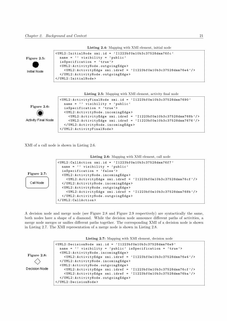
Chapter 2. Background and Context 21
Figure 2.5:
Listing 2.4: Mapping with XMI element, initial node
<UML2:InitialNode xmi.id = ’I1223bf0m10b3c37528dmm76fc ’
name = ’’ visibility = ’public ’
isSpecification = ’true’>
<UML2:ActivityNode.outgoingEdge >
<UML2:ActivityEdge xmi.idref = ’I1223bf0m10b3c37528dmm76e4 ’/>
</UML2:ActivityNode.outgoingEdge >
</UML2:InitialNode >
Figure 2.6:
Listing 2.5: Mapping with XMI element, activity final node
<UML2:ActivityFinalNode xmi.id = ’I1223bf0m10b3c37528dmm7690 ’
name = ’’ visibility = ’public ’
isSpecification = ’true’>
<UML2:ActivityNode.incomingEdge >
<UML2:ActivityEdge xmi.idref = ’I1223bf0m10b3c37528dmm768b ’/>
<UML2:ActivityEdge xmi.idref = ’I1223bf0m10b3c37528dmm7676 ’/>
</UML2:ActivityNode.incomingEdge >
</UML2:ActivityFinalNode >
XMI of a call node is shown in Listing 2.6.
Figure 2.7:
Listing 2.6: Mapping with XMI element, call node
<UML2:CallAction xmi.id = ’I1223bf0m10b3c37528dmm76f7 ’
name = ’’ visibility = ’public ’
isSpecification = ’false ’>
<UML2:ActivityNode.incomingEdge >
<UML2:ActivityEdge xmi.idref = ’I1223bf0m10b3c37528dmm76cf ’/>
</UML2:ActivityNode.incomingEdge >
<UML2:ActivityNode.outgoingEdge >
<UML2:ActivityEdge xmi.idref = ’I1223bf0m10b3c37528dmm768b ’/>
</UML2:ActivityNode.outgoingEdge >
</UML2:CallAction >
A decision node and merge node (see Figure 2.8 and Figure 2.9 respectively) are syntactically the same,both nodes have a shape of a diamond. While the decision node announce different paths of activities, amerge node merges or unifies different paths together. The corresponding XMI of a decision node is shownin Listing 2.7. The XMI representation of a merge node is shown in Listing 2.8.
Figure 2.8:
Listing 2.7: Mapping with XMI element, decision node
<UML2:DecisionNode xmi.id = ’I1223bf0m10b3c37528dmm76e9 ’
name = ’’ visibility = ’public ’ isSpecification = ’true’>
<UML2:ActivityNode.incomingEdge >
<UML2:ActivityEdge xmi.idref = ’I1223bf0m10b3c37528dmm76e4 ’/>
</UML2:ActivityNode.incomingEdge >
<UML2:ActivityNode.outgoingEdge >
<UML2:ActivityEdge xmi.idref = ’I1223bf0m10b3c37528dmm76cf ’/>
<UML2:ActivityEdge xmi.idref = ’I1223bf0m10b3c37528dmm76ba ’/>
</UML2:ActivityNode.outgoingEdge >
</UML2:DecisionNode >

22 2.4. Mapping between UML behaviour diagrams and XMI
Figure 2.9:
Listing 2.8: Mapping with XMI element, merge node
<UML2:MergeNode xmi.id = ’I1223bf0m10b3c37528dmm7762 ’
name = ’’ visibility = ’public ’ isSpecification = ’true’>
<UML2:ActivityNode.incomingEdge >
<UML2:ActivityEdge xmi.idref = ’I1223bf0m10b3c37528dmm77ce ’/>
<UML2:ActivityEdge xmi.idref = ’I1223bf0m10b3c37528dmm775d ’/>
</UML2:ActivityNode.incomingEdge >
<UML2:ActivityNode.outgoingEdge >
<UML2:ActivityEdge xmi.idref = ’I1223bf0m10b3c37528dmm77f0 ’/>
<UML2:ActivityEdge xmi.idref = ’I1223bf0m10b3c37528dmm7723 ’/>
</UML2:ActivityNode.outgoingEdge >
</UML2:MergeNode >
2.4.2 Mapping between state diagram and XMI
We performed the same steps as we did for the activity diagrams. We made state diagrams and placedthem at several places in the tree of the UML project. For each state diagram we tried to model all possiblecombinations between the different (UML) state elements and relations. Just like the activity, the positionof a state diagram in the UML project determines how the diagrams are announced.
A state diagram is separated in two parts, namely Region.subvertex and Region.transition. The Region.
subvertex contains all states and substates information. The Region.transition contains transitions (rela-tions between states) information.
Each relation (transition) contains information which triggered the transition (Transition.source) and thetarget state (Transition.target). Some relations also have a guard which is saved as Transition.guard. Theguard is an expression which must be true in order to trigger the target state.
An example of a relation without a guard is shown in Figure 2.10 and its corresponding XMI is shown inListing 2.9. An example of a relation with a guard is shown in Figure 2.11. The corresponding XMI is shownin Listing 2.10.
Figure 2.10:Listing 2.9: Mapping with XMI element, relation without guard
<UML2:Transition xmi.id = ’I98a7ebm10cd42e77e6mm55a4 ’
visibility = ’public ’ isSpecification = ’false ’
kind = ’external ’>
<UML2:Transition.source >
<UML2:State xmi.idref = ’I98a7ebm10cd42e77e6mm55a9 ’/>
</UML2:Transition.source >
<UML2:Transition.target >
<UML2:State xmi.idref = ’I98a7ebm10cd42e77e6mm55b4 ’/>
</UML2:Transition.target >
</UML2:Transition >
Like the activity diagram, the state diagram also has an initial and final node. However, in this diagramthese nodes are known as initial state (see Figure 2.12) and final state (see Figure 2.13) respectively. Theinitial state has a outgoing relation to a state. It cannot have more than one relation to a particular state.The final state has one or more incoming relations from a particular state to itself. The corresponding XMIof an initial node is shown in Listing 2.11, while the XMI source code of a final state is shown in Listing2.12.
A state is a condition or situation and can have one or more incoming and outgoing relations. It has theshape of a rounded rectangle (see Figure 2.14). The state Simple State that has one incoming and oneoutgoing relation is shown in Listing 2.13.

Chapter 2. Background and Context 23
Figure 2.11:
Listing 2.10: Mapping with XMI element, relation with guard
<UML2:Transition xmi.id = ’I98a7ebm10cd42e77e6mm54f0 ’
visibility = ’public ’ isSpecification = ’false ’
kind = ’external ’>
<UML2:Transition.source >
<UML2:State xmi.idref = ’I98a7ebm10cd42e77e6mm5658 ’/>
</UML2:Transition.source >
<UML2:Transition.target >
<UML2:State xmi.idref = ’I98a7ebm10cd42e77e6mm55e0 ’/>
</UML2:Transition.target >
<UML2:Transition.guard>
<UML2:Constraint xmi.id = ’I98a7ebm10cd42e77e6mm54db ’
name = ’’ visibility = ’public ’ isSpecification = ’false ’>
<UML2:Constraint.specification >
<UML2:OpaqueExpression xmi.id = ’I98a7ebm10cd42e77e6mm54d4 ’
name = ’’ visibility = ’public ’ isSpecification = ’false ’
body = ’temp >= 20’ language = ’java’/>
</UML2:Constraint.specification >
</UML2:Constraint >
</UML2:Transition.guard>
</UML2:Transition >
Figure 2.12:
Listing 2.11: Mapping with XMI element, initial state
<UML2:Pseudostate xmi.id = ’I734770m10c483e9153mm57a8 ’
name = ’’ visibility = ’public ’ isSpecification = ’false ’
kind = ’initial ’>
<UML2:Vertex.outgoing >
<UML2:Transition xmi.idref = ’I98a7ebm10cd42e77e6mm5642 ’/>
</UML2:Vertex.outgoing >
</UML2:Pseudostate >
Figure 2.13:
Listing 2.12: Mapping with XMI element, final state
<UML2:FinalState xmi.id = ’I19b60bbm10cd45e4e27mm7b2b ’
name = ’’ visibility = ’public ’ isSpecification = ’false ’>
<UML2:Vertex.incoming >
<UML2:Transition xmi.idref = ’I98a7ebm10cd42e77e6mm565g ’/>
</UML2:Vertex.incoming >
</UML2:FinalState >
Figure 2.14:
Listing 2.13: Mapping with XMI element, simple state
<UML2:State xmi.id = ’I98a7ebm10cd42e77e6mm564d ’
name = ’Simple State ’ visibility = ’public ’
isSpecification = ’false’>
<UML2:Vertex.outgoing >
<UML2:Transition xmi.idref = ’I98a7ebm10cd42e77e6mm55ce ’/>
</UML2:Vertex.outgoing >
<UML2:Vertex.incoming >
<UML2:Transition xmi.idref = ’I98a7ebm10cd42e77e6mm562d ’/>
</UML2:Vertex.incoming >
</UML2:State >

24 2.5. Implementation languages
The composite state is a state that contains other substates or nonorthogonal states. States that are nota part of the composite state can have a relation with the composite state or a substate in the compositestate. A composite may have at most one initial and final state. An example of a composite state is shownin Figure 2.15 and is saved in the XMI format as shown in Listing 2.14. Note that the XMI only containsthe structure of a composite. The substates are omitted and are referred as <!-- Content of region -->.
Figure 2.15:
Listing 2.14: Mapping with XMI element, composite state
<UML2:State xmi.id = ’I98a7ebm10cd42e77e6mm55e0 ’
name = ’Composite_State_1 ’ visibility = ’public ’
isSpecification = ’false’>
<UML2:Vertex.incoming >
<UML2:Transition
xmi.idref = ’I98a7ebm10cd42e77e6mm54f0 ’/>
</UML2:Vertex.incoming >
<UML2:State.region >
<UML2:Region xmi.id = ’I98a7ebm10cd42e77e6mm55df ’
name = ’Region_1 ’ visibility = ’public ’
isSpecification = ’false’>
<UML2:Region.subvertex >
<!-- Content of region -->
</UML2:Region.subvertex >
</UML2:Region >
</UML2:State.region >
</UML2:State >
The orthogonal state is similar to a composite state. The difference is that the orthogonal state have twoor more state machines (regions) that execute in parallel in the context of the enclosing object. Eachregion has only one initial and final states. An example of an orthogonal state is shown in Figure 2.16. Amapping with the XMI is shown in Listing 2.15. Note that the content of two state machines are saved in<!-- Content of region 1 --> and in <!-- Content of region 2 -->.
A submachine is actually a reference to another state machine. A submachine is shown in Figure 2.17 andthe corresponding XMI is shown in Listing 2.16. Note that the figure does not have a reference yet, butin the XMI source we can see it has a reference to another state diagram where xmi.idref has the valueI734770m10c483e9153mm7cf1.
Note that there are different kinds of states (simple, composite, and orthogonal). Unlike activity diagramwhere every different element has another element name, all states are saved with the element name State.The only difference between the composite and the orthogonal state is that the orthogonal has more thanone region that contains substates.
2.5 Implementation languages
We have chosen for XSLT and ASF+SDF as potential implementation language for the transformers that wemake (see Figure 1.1). Both techniques are designed for making transformations between different formats.
We evaluate for each transformer which technique is the best to use as implementation language. Theevaluations are based on our understanding of the techniques as discussed below.
2.5.1 XSLT
XSLT is an abbreviation for eXtensible Stylesheet Language Transformations. It is developed by the W3Corganisation especially for transformations of XML documents. XSLT is a core technology for processing

Chapter 2. Background and Context 25
Figure 2.16:
Listing 2.15: Mapping with XMI element, orthogonal state
<UML2:State xmi.id = ’I1ebbfdem10cd477175amm7afd ’
name = ’Orthogonal_State_1 ’ visibility = ’public ’
isSpecification = ’false’>
<UML2:Vertex.outgoing >
<UML2:Transition
xmi.idref = ’I1ebbfdem10cd477175amm79a7 ’/>
</UML2:Vertex.outgoing >
<UML2:Vertex.incoming >
<UML2:Transition
xmi.idref = ’I1ebbfdem10cd477175amm79c8 ’/>
</UML2:Vertex.incoming >
<UML2:State.region >
<UML2:Region xmi.id = ’I1ebbfdem10cd477175amm7afc ’
name = ’Region_1 ’ visibility = ’public ’
isSpecification = ’false’>
<!-- Content of region 1 -->
</UML2:Region >
<UML2:Region xmi.id = ’I1ebbfdem10cd477175amm7afb ’
name = ’Region_2 ’ visibility = ’public ’
isSpecification = ’false’>
<!-- Content of region 2 -->
</UML2:Region >
</UML2:State.region >
</UML2:State >
Figure 2.17:
Listing 2.16: Mapping with XMI element, submachine
<UML2:State xmi.id = ’I734770m10c483e9153mm7ce8 ’
name = ’Submachine_State_1 ’ visibility = ’public ’
isSpecification = ’false ’>
<UML2:State.submachine >
<UML2:StateMachine
xmi.idref = ’I734770m10c483e9153mm7cf1 ’/>
</UML2:State.submachine >
</UML2:State >

26 2.5. Implementation languages
XML.
XSLT is a general-purpose translation tool, a system for reorganising document content, and a way togenerate multiple results from the same content. With XSLT we can add/remove elements and attributes toor from the output file. We can also rearrange and sort elements, perform tests and make decisions aboutwhich elements to hide and display, et cetera.
Using XSLT we can easily traverse through XML based documents and select particular data or transforma particular part of the tree into another presentation like HTML, webpages, WAP, and SVG. We only haveto give the element name, which XSLT uses to match the elements and place the information in the holes ofa template.
However, an element will only be transformed if the corresponding template is called. So, when developinga transformer in XSLT, the engineer has to know exactly where elements can appear, because it is very easyto miss some elements. This can lead to a transformed document where information is lost.
Because the XSLT processor has no knowledge of the target language, transformers which are implementedin this language cannot ensure that the target presentation has the correct syntax. However, if we transformthe code into another XML based format, the XSLT processor will take care that the generated documentdoes conform to the XML syntax.
XSLT does not have a stack machine that manages the creation and initialisation of the variables. Allvariables that are used can remember one value while processing only. If a variable is assigned a new value,the old one will be lost. As a consequence, recursive calls are not possible, if the called template containsvariables.
The language has a limited set of functions, which we can use to modify characters. It is possible to extendthe functions in XSLT, but then we need knowledge about another technology like (javascript) scriptinglanguage or C# (to extend the XSLT processor), or we use EXSLT (Extended XSLT4).
Because XSLT is standard used by engineers to transform XML, we want to use it as an implementationlanguage for the transformers that we make. More about XSLT can be found in [ABC+01, Cla99]. Aconsequence of this is that we probably have to change the XSLT processor. Note that we use Apache’sopen source XSLT parser and processor.
2.5.2 ASF+SDF
The specification formalism ASF+SDF is a combination of the algebraic specification formalism ASF andthe syntax definition formalism SDF. It is a specification language where we can define the syntax and thesemantics of programming languages. We can also specify rewrite rules for a compiler or a transformer,which transforms Java source code to byte code for example.
Unlike XSLT, we can transform any language into another as long as we have the grammars of the languages.As a result, the benefit of using ASF+SDF as implementation language is that we can ensure that the targetpresentation is correct. Although this also can be seen as a drawback, because we always have to have thegrammar of the target language. For example, if we want to transform an XMI into a text file with out anyformat, we have to define a grammar for that text.
Functions are defined and saved in two different parts. The syntax of a function is defined in the SDF part,while the rewrite rules of that function are defined in the ASF part. So, if we have to modify a function, weprobably have to make a change in the ASF part. Then we also have to check other functions that use thatparticular function.
Depending on the type of functions (whether those are traversals) that do the transformation, we sometimesneed more rules to perform a transformation than in the case of XSLT. As a consequence, the implementationof a transformer can be very large.
4http://www.exslt.org/

Chapter 2. Background and Context 27
While making a transformer in ASF+SDF, we do not have to worry about the values that are saved increated variables. The variables of the rewrite rules are saved on a stack. Each time a rewrite rule is applied,new variables are created. When a rewrite rule is finished, old variables will be thrown away.
In ASF+SDF there are no predefined functions to modify characters of a lexical sort, except for the lexicalconstructor functions. Functions have to be created for every modification that is needed. The benefit isthat it results in a set of functions that is very expressive. The drawback is that it takes the engineer moretime to develop a transformer.
We want to use ASF+SDF as an potentional implementation language, because the weakness of XSLT isthe strength of ASF+SDF and vice versa. Another reason is because we already are acquainted with thislanguage. Literature about ASF+SDF can be found in [BK05].
2.6 Template-based generator
The template-based generator described in [Arn06] takes a BAST (see Section 2.6.1) and templates as inputin order to generate source code. The generator has no name yet, so we will refer to it as ‘template-basedgenerator’.
The generator is similar to the processor of XSLT. Like the XSLT processor, it also traverse through a treein a fixed format by means of a given selection query. The query language, which the generator uses, hasthe same control constructs as XSLT. The biggest difference between the XSLT processor and the generatoris that the latter generates syntactically correct code.
Before the generation process, the generator parses the given template(s) and the BAST. A template containsholes, which are instructions for the generator to traverse through the tree. In this way, the generator ensuresthat the generated source code is correct. A notable thing is that the generator can generate more than justone language, like Java, C++, C, et cetera [Arn06].
The generator is implemented in ASF+SDF.
Why we use this generator
We could make a generator by ourselves, which transforms our XML-based document into Java. To make surethat the generated Java code is also syntactically correct, we could implement the generator in ASF+SDF. Inthe end we would get a generator, which is functionality actually the same as the template-based generator.
The difference between our implementation and the template-based generator is that our generator wouldonly generate Java code, because that is what we want to generate.
If we use the template-based generator, we still have to make a transformer that transforms the interformatinto a BAST. Unlike the Java grammar, the BAST grammar is very small. This will save us much time inorder to become acquainted with it.
2.6.1 Balance Abstract Syntax Tree
The BAST (Balance Abstract Syntax Tree) is a format that is used as input for a template-based generator.As the name of BAST already suggest, the format has a structure of a tree and it starts with the keywordbAST (see Listing 2.17) [Arn06].
Listing 2.17: SDF definition of BAST, rule one
"bAST" "(" "[" {BRecord ","}* "]" ")" -> BAST

28 2.6. Template-based generator
The tree consist of a list with four different sorts, namely a bDomain, bLookup, bClass, and a bAttribute. Weneed to use the last two sorts in order to define a class and its attributes. Note that the first two sorts areused to represent data from the database domain. The syntax definition of the sorts are shown in Listing2.18.
Listing 2.18: SDF definition of BAST, the four different sorts
BProperty | BClass | BLookup | BDomain -> BRecord
"bDomain" "(" "[" { BProperty "," }+ "]" ")" -> BDomain
"bLookup" "(" "[" { BProperty "," }+ "]" ")" -> BLookup
"bClass" "(" "[" { BClassItem "," }+ "]" ")" -> BClass
"bAttribute" "(" "[" { BProperty ","}* "]" ")" -> BAttribute
BProperty | BAttribute -> BClassItem
A bProperty is indicated with a given custom name (UQLiteral "("BElem ")") that can contain a primitivesort. The four sorts that are possible are real, int, bool, and string. We have shown the syntax of thesesorts in Listing 2.19.
Listing 2.19: SDF definition of BAST, the four primitive sorts
UQLiteral "(" BElem ")" -> BProperty {cons("belem")}
"bool" "(" real -value:BoolCon ")" -> BElem {cons("bool")}
"real" "(" real -value:RealCon ")" -> BElem {cons("real")}
"int" "(" int -value:IntCon ")" -> BElem {cons("int")}
"str" "(" str -value:StrCon ")" -> BElem {cons("str")}
The syntax of the BAST gives us the possibility to define a part of the tree. However, because we do notgenerate source code where attributes are the main issue. We also need a sort that we can use to define ourJava operations. This issue will be discussed in Section 3.6.
The difference between BAST and XMI
There are two differences between the BAST format and the XMI format. The first difference is that aBAST does not have references to other elements in the tree, while an XMI does. An XMI can also havereferences to elements in other documents or even a whole document. This makes a BAST very verbose.
The second difference is that elements in a BAST has only a small set of sorts to indicate the data, whilean XMI has many (142) different elements.
2.6.2 Templates for the template-based generator
Like every template, this templates contains holes, which will be used by the generator to fill it up withdata. The holes are indicated with <% expression %>. The expression that is defined in the holes matcheswith a given custom name or a sort.
The expressions are similar to the expressions in XSLT. The difference is that it is possible to define smallreusable templates in XSLT, while the expression is a part of a template in our case. If we want to reusethe same data, we have to define the expression again.
Fortunately, it is possible to use <%for each ... do%> to repeat the same defined action. An example of atemplate for generating classes is shown in Listing 2.20.
Listing 2.20: A template that is used by the template-based generator
<%for each bClass in bAST do

Chapter 2. Background and Context 29
//Save each class in a file as follows <class name >.java
store in <%.bAST.name%>/<%name || ".java"%>
%>
package <%containedPackage %>;
<%for each bImportPkg do%>
// Imported packages
import <%path%>;
<%od%>
// class declaration
<%accessModifier%> <%fieldModifier%> <%name%>
<%if .bAST.inheritanceExtends != "" %>
extends <%inheritanceExtends%>
<%fi%>
<%for each bIInheritance do%>
implements <%inheritanceImplements%>
<%od%>
{
// Attributes
<%for each bAttribute do%>
<%accessModifier%> <%fieldModifier%> <%type%> <%name%>;
<%od%>
// Operations
<%for each bOperation do%>
<%accessModifier%> <%fieldModifier%> <%returnStmt%> <%name%>(
<%for each bArgument do%>
<%type%> <%name%>
<%od%>
){
<%body%>
}
<%od%>
}
<%od%>

30 2.6. Template-based generator

Chapter 3
Plan Execution
Introduction
We already gave a high-level overview of our research plan in Section 1.3. In this section we discuss thosesteps in more detail. The execution of our research plan contains the following steps.
1. Selecting UML diagrams and UML tool (Section 3.1).
2. Making a UML profile for more expressiveness (Section 3.2).
3. Transforming XMI into Interformat (Section 3.3).
4. Resolving the stereotypes (Section 3.4).
5. Merging behaviour diagrams with a class diagram (Section 3.5).
6. Transforming Interformat into BAST (Section 3.6).
7. Generating Java source code (Section 3.7).
8. Verifying generated source code with the Java test case system (Section 3.8).
Note that the sequence of the steps differ slightly with the previous presented plan. Instead of discussingthe Java test case system (second step in the research plan) as the second step in this chapter, we movedthat section to the last step. The reason is because the discussion of the Java system is not needed for thegeneration process untill we validate the generated source code.
3.1 Selecting UML diagrams and UML tool
We have already mentioned the diagrams that we have selected, which we will use in this project (classdiagram, activity diagram, and sequence diagram). We discuss why we have selected this subset in Section3.1.1. Note that this section gives answer to the research subquestion ‘Which behaviour diagrams are suitedfor generating behavioural source code?’
The discussion about which UML tool we select can be found in Section 3.1.2, because a UML tool hasinfluence on the UML and XMI version.
31

32 3.1. Selecting UML diagrams and UML tool
3.1.1 Diagram selection
For the selection of diagrams we have studied [DLS+02, DSTW04, KNNZ00, RFW+04] to find out whichdiagrams are really needed for code generation. The conclusion is that the common diagrams that are usedfor code generation are class diagram and state diagram, because these two diagrams cover the static andthe dynamic part of a system.
However, we miss a diagram in which we can specify the (control) flow of activities. So, we select anotherdiagram that compensates this. We can specify the latter with the sequence diagram and the activitydiagram, because we can show activities between various objects with both diagrams. Note that statediagram shows the control flow of states.
We investigated how sequence diagrams are saved. The sequence diagrams are, like activity and statediagrams, saved in two parts. However, unlike those two other diagrams, the sequences do not have aninitial node. The sequence of the messages (communication between objects) depends on the layout of adiagram. As a consequence, we have to use the layout of the diagram in order to generate source code. So,we have chosen to use the actvitiy diagram instead of the sequence diagram.
Class diagram As mentioned, a class diagram shows a collection of classes, interfaces, and collaborationsand their relationships. Each class contains a class name, class attributes and methods (also mentioned asoperations in [BRJ05]). This diagram contains enough information to generate code. We treat the classdiagram as a basic diagram.
This diagram has a one to one mapping with the source code. As a result, generation from this diagram isnot very difficult. By using this diagram for generation we also satisfy the requirement ‘the architecture ofthe generated code should be the same as the code that is developed manually’ (see Section 1.3).
State diagram Many systems have at least two states (idle and active). So, engineers can always use astate diagram to model these states. A state diagram can be modelled on all precision levels (architecture,class, method, and attribute). A state diagram is a useful diagram in order to find activities of classes, butit does not contain enough information to generate source code.
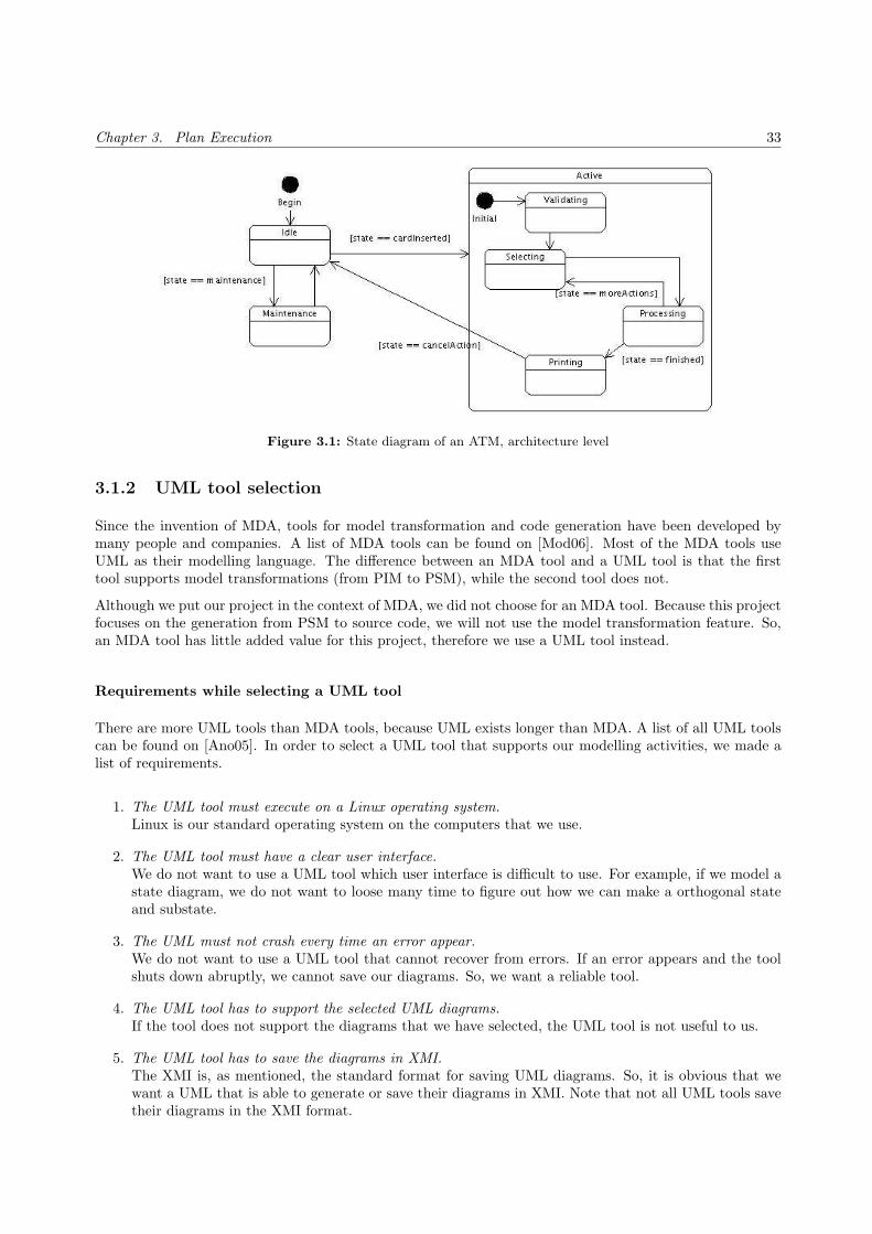
For example, a state diagram of an ATM contains a substate Validating (see Figure 3.1). When engineers seethis state diagram, they know what validation means and what the system has to do. However, a generatorhas not the same intelligence as humans have. So, the generator is not able to generate code for the substateValidating. The generator will be able to generate source code in this situation, if the word Validating is akeyword which the generator uses. In addition, the generator must have knowledge of a specific domain (inthis case about ATMs), which makes the generator less reusable for other purposes.
Although the state diagram of the example is modelled on the architecture level, the problem of missinginformation also applies for other levels. We use the do-activity of a state diagram to specify the actionwithin a state.
Activity diagram We want to use the activity diagram to model the body of a method at the attributelevel, because this diagram gives us the possibility to model the activity between objects.
The problem with activity diagrams is that abstraction is lost when it is modelled at the attribute level,because the activities contain statements of a particular programming language like Student student =
new Student();. It seems that this is not the intension of UML, but in [BRJ05] they have shown thatit is permitted. However, modelling activity diagram at this (attribute) level ‘lies on the edge of making theUML a visual programming language [BRJ05].’
Chapter 3. Plan Execution 33
Figure 3.1: State diagram of an ATM, architecture level
3.1.2 UML tool selection
Since the invention of MDA, tools for model transformation and code generation have been developed bymany people and companies. A list of MDA tools can be found on [Mod06]. Most of the MDA tools useUML as their modelling language. The difference between an MDA tool and a UML tool is that the firsttool supports model transformations (from PIM to PSM), while the second tool does not.
Although we put our project in the context of MDA, we did not choose for an MDA tool. Because this projectfocuses on the generation from PSM to source code, we will not use the model transformation feature. So,an MDA tool has little added value for this project, therefore we use a UML tool instead.
Requirements while selecting a UML tool
There are more UML tools than MDA tools, because UML exists longer than MDA. A list of all UML toolscan be found on [Ano05]. In order to select a UML tool that supports our modelling activities, we made alist of requirements.
1. The UML tool must execute on a Linux operating system.Linux is our standard operating system on the computers that we use.
2. The UML tool must have a clear user interface.We do not want to use a UML tool which user interface is difficult to use. For example, if we model astate diagram, we do not want to loose many time to figure out how we can make a orthogonal stateand substate.
3. The UML must not crash every time an error appear.We do not want to use a UML tool that cannot recover from errors. If an error appears and the toolshuts down abruptly, we cannot save our diagrams. So, we want a reliable tool.
4. The UML tool has to support the selected UML diagrams.If the tool does not support the diagrams that we have selected, the UML tool is not useful to us.
5. The UML tool has to save the diagrams in XMI.The XMI is, as mentioned, the standard format for saving UML diagrams. So, it is obvious that wewant a UML that is able to generate or save their diagrams in XMI. Note that not all UML tools savetheir diagrams in the XMI format.

34 3.1. Selecting UML diagrams and UML tool
6. A UML tool that supports UML 2.0 is preferred.UML 2.0 is particularly extended to support the modelling and transformations of MDA. It is obviousthat we use UML 2.0 as our modelling language. However, many UML tools do not support this versionof UML yet. So, we prefer UML tools that support UML 2.0, but it is not a obligatory requirement.
7. The UML tool must be free of charge, but it does not need to be open source.We want a UML tool that is free of charge, because we do not have a budget in order to buy one.
8. The UML tool may limit the features, but it must not limit the modelling.A consequence of using free tools of companies, i.e. not open source tools, is that the number offeatures are limited. We do not mind that a UML tool does not support a copy and paste feature in afree edition, because it does not limit us in modelling. An example of limitation of modelling is thatsome tools limit the number of elements in a diagram.
Comparing the tools
We have selected a few tools that are open source or free of charge from the list of UML tools, which canbe found on [Ano05]. We have compared UML tools whether they satisfy the defined requirements. Anoverview of the analysed UML tools is in Table 3.1.
Commercial companies have a community edition that is freely available. However, many of them limitthe possibility to model diagrams. We found out that VP-UML Community Edition, EclipseUML FreeEdition, and Objecteering UML limit its modelling features, but they did not mention it on the website ofthe company. If we wanted to use a feature that was not a part of the community edition, a pop-up appearedwith the question whether we wanted to buy another edition.
We have also installed the open source tools like ArgoUML and Umbrello and evaluated their reliability.However, every time an error appeared, the tools shut down abruptly or did not respond anymore when anerror occurred. The project files became corrupted. So, all effort that we put in that project was gone andwe had to start all over again.
While comparing the tools we noticed that the free commercial tools have a better reliability than those thatare open source. On the other hand, the open source tools have no pop-ups.
Tool that we have chosen
After comparing the tools we have chosen for Gentleware’s Poseidon for UML Community Edition. Poseidonis based on the open source and free tool called ArgoUML. The basic version of Gentleware’s tool suite,Poseidon for UML Community Edition, is free of charge for non-commercial use. The community edition ofthis UML tool meets requirement seven, because of the latter.
We have installed Poseidon on our machine and worked with it. Although errors appeared while we weretesting the tool, we did not get any annoying pop-ups. Note that the console showed some errors. The mostimportant issue is that our work is preserved without becoming corrupt. So, the tool meets the requirementsnumber one and two.
Poseidon for UML is more feature rich and more stable than ArgoUML. So, Poseidon meets the requirementnumber three. It is intended for your daily work in commercial and professional environments. ArgoUML,on the other hand, is open source and lends itself for research, study of the architecture and for extensibility.However, we are not using the UML tool as a research object, but as a means that we use to generate XMI.
We can gain an XMI file of our working project in two ways. We can get the XMI file from the project files,which Poseidon saves as a zip file, or we let Poseidon generate the XMI file. Both ways will result in an XMIfile with the same content and XMI version (1.2). This feature of saving and generating the content in XMIformat meets the fifth requirement.

Chapter 3. Plan Execution 35
UML 2.0 is integrated in Poseidon since version 4.0 and it supports the modelling of nine diagrams (seeTable 3.1). As a result it also meets the requirements four and six.
The difference between these two is that Poseidon has a better performance, a better graphical user interface,and a different way of saving its diagrams in XMI format. The XMI version in which Poseidon saves itsdiagrams is 1.2, while diagrams are modelled in version 2.0.
Note that MagicDraw has the same results as Poseidon, but we are more acquainted with the latter. Thatis why we have chosen for Poseidon instead of MagicDraw.
3.2 Making a UML profile for more expressiveness
We have identified the problems of generating behavioural source code in Section 1.1.
We think that these problems are caused by UML that misses expressiveness. In this section we try tosolve these problems by making UML more expressive. In Section 2.2 we discussed the two different ways ofextending UML, namely metamodelling and UML profile.
First, we discuss why we have chosen for UML profile to extend UML. Second, we discuss the UML profilethat we use during the modelling. Last, we discuss the rules and restrictions that we have beside the UMLprofile.
Note that this section gives answers to two research subquestions, namely ‘How can we constrain the mod-elling possibilities and simultaneously increase the expressiveness in behaviour diagrams?’ and ‘How can wemake the mapping between structure and behaviour diagrams clear?’.
3.2.1 Extending UML: metamodelling or UML profile
[SW06] presents an industrial case study on the choice between metamodel extensions and profiles. Theyalso investigated the influence of the choice on quality of products based on the extensions.
In the paper, they came to the conclusion that there is no single decisive factor whether to choose profilesor metamodels. The most important criteria are the expressiveness of the approaches and the knowledgerequired for development.
Another conclusion is that customising UML by means of metamodelling is harder than defining a profile.They also present that products based on profiles cause less faults and are of better quality. It also costsless time to define a profile and profiles are easier to develop by many engineers. The benefit of using ametamodel is that the modelling language is more powerfull. It is then possible to define new relations andelements.
Based on the results of this paper we have decided to customise UML with profiles.
3.2.2 Defining a UML profile
In this section we discuss the UML profile that we use. As mentioned in Section 2.2 a profile is a set ofpredefined stereotypes, tagged values, constraints, and base classes (official definition given in [BRJ05]).
If we use the official definition of a UML profile, then we have only defined several stereotypes. We have notspecified any tagged values and constraints, because we do not need them in this project to let our generatorgenerate behavioural source code. We are aware that specification of these parts can be needed in othersituations.

36 3.2. Making a UML profile for more expressiveness
Requirem
ents
UM
Ltool
(version)
UML version
12
34
56
78
XMI version
*Com
ment
ArgoU
ML
(0.18)1.3
++
-+
+-
f+
1.2W
ecan
useall
itsfeatures
form
odelling.H
owever,
itcrashes
everytime
anerror
occuredG
entleware
Poseidon
Com
muni-
tyE
dition(4.1)
2.0+
++
++
+f
+1.2
Selectedtool.
Some
featuresare
notsupported
inthis
edi-tion,
butdoes
notlim
itthe
modelling.
BO
UM
L(2.12.1)
1.4x
-u
-*
+f
+1.01.2
We
worked
with
thetool
fora
while,
butw
ew
erenot
ableto
model
anydiagram
.U
mbrello
Modeller
(1.5.1)1.3
++
-+
+-
f+
1.2U
MLet
(6)u
++
/-u
++
-f
+u
Plug-in
forE
clipseV
P-U
ML
Com
munity
Edition
(5.2)≤
2.0+
++
++
+f
-1.01.22.1
Annoying
pop-upsabout
featuresin
othereditions
andlim
-itation
inthe
modelling
No
Magic
MagicD
rawC
omm
u-nity
Edition
(11.0)2.0
++
++
++
f+
1.01.11.22.1
Perform
anceis
low.
EclipseU
ML
FreeE
dition(2.1.0)
2.0+
++
+-
+f
-n
Plug-in
forE
clipse.V
iolet(0.17.3)
u+
+u
--
-f
+n
Plug-in
forE
clipse.O
bjecteering
UM
LPersonalE
di-tion
(5.3.0SP
2)1.31.4
++
++
+-
f-
1.01.1
ESS-M
odel(2.2)
u+
-u
-+
-f
+u
+=
satisfiesthe
requirement,
-=
notsupported/does
notsatisy
therequirem
ent,f=
freeedition,
u=
unknown
Table
3.1
:U
ML
tools
which
we
hav
eanaly
sedfo
rth
isresea
rch.

Chapter 3. Plan Execution 37
Although we do not specify UML profile constraints, we do have other constraints. The difference withUML profile constraints and the latter is that we do not use free-form text, and it is only applicable on ahigher level. While the UML profile constraints are about specifing the elements and the relations between,our constraints is about limiting the usage of UML elements. In order to avoid the ambiguity of the termconstraint we use restriction instead to indicate our constraints.
First, we discuss the stereotypes that we have defined for our UML profile. Then, we discuss the restrictionsthat we have defined.
Defined stereotypes and usage
The notation for stereotypes that we use is different from the official one. Instead of defining it as a typewhich is shown above the name in the format << type >>, we put it as a prefix in a behavioural UML element(activity). We have shown the difference of notation in Figure 3.2 and Figure 3.3.
Figure 3.2: Activity with official stereotype notation Figure 3.3: Activity with our stereotype notation
Poseidon saves each stereotype that we create as an XMI element. For every other type of UML diagram awhole new set of stereotypes will be created. As a consequence, the XMI contains duplicates of the createdstereotypes. An example of duplicated stereotypes is shown in Listing 3.1. Note that ... indicate someomitted data. In order to limit the references to other XMI elements and duplicated stereotypes, we put thestereotypes as the prefix of an action.
Listing 3.1: Example of duplicated stereotypes in XMI
...
<UML:Stereotype xmi.id = ’dc6mm7165 ’ name = ’initializer ’ ... />
<UML:Stereotype xmi.id = ’dc6mm7687 ’ name = ’initializer ’ ... />
...
We have defined five different stereotypes to indicate an action (ACTION: and PRINT:), a begin (BEGIN:), oran end (END:). The stereotypes can be used in the activity diagram as well as in the state diagram.
It seems a bit strange to have a ACTION: stereotype that can be used for an activity. However, this stereotypehas another purpose than an activity on its own. This stereotype is used to collect activities that shouldexecute sequential, like generating new instances for attributes. In this way we can model an action in aconsise way. This stereotype has a specific syntax, which is shown in Listing 3.2. Note that we use SDF tospecify the syntax.
Listing 3.2: Syntax definition, ACTION:
"ACTION:" ClassName "." Elements "." ActionActivity -> Action
[A-Za -z\_\$] [A-Za -z0 -9\_\$]* -> ClassName
"objects" | "attributes" | "methods" -> Elements
"GET_METHODS" | "SET_METHODS" | "NEW_INSTANCES" -> ActionActivity
There are some situations where we want to print a variable on the screen, console, or save the informationin a file. For these situations we have defined a stereotype PRINT: that can be used to print attributes or a

38 3.2. Making a UML profile for more expressiveness
string. In this way, the engineer does not have to give all the statements of the implementation in order toprint the specific attribute or string in the activities.
In this project, we only support printing attributes in the console (System.out.println(""+attributeName.toString());). The syntax definition for the PRINT: tag is shown in Listing 3.3. Note that we omitted somecharacters and replaced it by ....
Listing 3.3: Syntax definition, PRINT:
"PRINT:" AttributeName "." PrintActivity -> Print
"PRINT:" "\"" UDString "\"" "." PrintActivity -> Print
[A-Za-z\_\$] [A-Za-z0 -9\_\$]* -> AttributeName
[A-Za-z0 -9 ... \{\}] -> UDString
"CONSOLE" -> PrintActivity
The BEGIN: and END: stereotypes are used to specify the modelled level (architecture, class, method, orattribute) of a diagram. These steretypes are used in the activity diagram as well as in the state diagram.Generating code from a diagram that is modelled on the class level is different than a diagram that ismodelled on the attribute level. That is why this stereotype is added. The syntax definition is shown inListing 3.4.
Listing 3.4: Syntax definition, BEGIN: and END:
"BEGIN:" Level -> Begin
"END:" Level -> End
"attribute" | "method" | "class" | "architecture" -> Level
We are aware that there are more possibilities with stereotypes than we use and have in our UML profile.We could, for example, make a stereotype EXCEPTION: for exception handling or CAST: to cast a particularobject to another. However, for this project we only need these types. In order to make this UML profileuseful for other research in the future, we take the extensibility of the UML profile into account, while wedefined the syntax.
In a later step we will use this syntax definition in order to transform these tags in Java source code (seeSection 3.4).
Diagrams that are modelled with our UML profile are mentioned as annotated diagrams in our project. Anexample of an annotated diagram is shown in Figure 3.4.
Figure 3.4: Activity diagram modelled at the attribute level
Figure 3.5: An activity diagram that is am-biguous

Chapter 3. Plan Execution 39
Restrictions in the modelling
As mentioned before, the difference between the UML profile constraints and these restrictions is thelevel on which they are applicable. The UML profile constraints is about specifing the elements and therelations between them by using operators (e.g. xor, or, and) and conditions (e.g. person1 == "male"
&& person2 == "female"), while our restrictions are about limiting the usage of UML elements by not allow-ing every construction in a diagram.
There are many ways possible to model a particular condition or sequence. Because of that, diagrams canbe ambiguous. An example of a diagram that is ambiguous is shown in Figure 3.5. The figure shows threedifferent activities (Action_1, Action_2, and Action_3) and three relations which trigger them. There arethree implementation possible with this diagram. (1) Only one condition can be true at a time, so only oneactivity will execute. (2) x will increase or decrease each time after executing an activity, so these activitiesare executed sequential. (3) Action_1, Action_2, and Action_3 are executed at the same moment (parallelexecution).
A generator cannot generate source code (or it generates bad source code) from an ambiguous diagram. Byrestricting the usage of the UML elements, we eliminate the problem ‘a behaviour can be implemented indifferent ways’ that we have defined in Section 1.1. A benefit of this kind of restrictions this is that wealways know when a conditional sequence stops. The restrictions that we have are defined as follows.
• The diagram must be saved at the same level and have the same name as the related UML element.It is not possible to relate a diagram to a method, a class, or an attribute in Poseidon. So, by givingthe behaviour diagram the name of the related UML element and save its position at the same level,we can map the diagrams with the structure diagram.
An example of this restriction is shown in Figure 3.6. The Figure shows a project tree that is opened inPoseidon, which contains four packages, one class, and two activity diagrams. Both activity diagramsare saved as a leaf of the class School. The unfolded activity diagram has the same name as the methodshowStudents() in the same class.
If we do not use the position of the diagrams for the mapping between structure and behaviour diagram,we need to give the diagrams the qualified name of the UML element. In the case of Figure 3.6, theactivity diagram must be named as school.School.showStudents(). Note that the diagram’s namemust also include the arguments of the method. The reason is because of the possibility of overloadingin Java. In this way we prevent generation of behaviour source code for the wrong method.
This restriction solves the mapping problem ‘the mapping between structure and behaviour diagrams isnot always clear’.
• Each state must contain an action in the do-activity section.We can generate source code from a state diagram that contains states without actions, but the resultingsource code will not contain behaviour. That is why behaviour or the activity of the state must beindicated with the do-activity (is shown as do/ in the diagram).
• Every activity and state diagram has only one initial node/state and has one or more final node/state.Except for composite state, which has only one initial and one final state.By limiting the initial node/state in each diagram, the generator knows where to start with generationof source code. For example, if an activity diagram is modelled on the attribute level, which is aexecution model of a method, it cannot have two initial nodes, because a method execution will alwaysstart at the beginning.
A final node/state is needed to know when an activity or state sequence is ended.
• An activity may have only one outgoing relation, but it may have a conditional relation to itself.In order to prevent ambiguity like shown in Figure 3.5, an activity may only have one outgoing relation.Except for a conditional relation to itself, because this relation indicates a repetition of the same action.

40 3.2. Making a UML profile for more expressiveness
• A decision element contains one or more conditional relations and may contain zero or one relationwithout a condition.A decision indicates a conditional execution. It is possible that a decision element has multiple con-ditional relations, because now we know that it is really a conditional execution instead of a parallelexecution. Because of that, it is also possible to have relation without a condition, which will be treatedas the default execution if nothing else is true.
• A conditional relation (a guard) can only be used after a decision element. It is not allowed to use aconditional relation between two activities.This restriction make decisions visible in diagrams. Although it seems like this rule overdo it whenthere is only one conditional relation between activities, it is needed for consistency with conditionalexecution.
• The sequence of a decision element (a shape of a diamond) must always be terminated with a finalelement (a circle within a circle) or a merge element (also a shape of a diamond).This restriction takes care of the fact that the conditional execution should be terminated in a well-formed way. An example of a good termination is shown in Figure 3.7.
Figure 3.6: Position of an activity, as leaf of a class node in theproject tree
Figure 3.7: An example of a conditional exe-cution that is terminated in a well-formed way
Results and consequences of using a UML profile
Activity diagrams and state diagrams, which are modelled by means of the UML profile on the attributelevel, have a one to one mapping with the source code. Althought a state diagram still needs an activitydiagram that specifies the states, we are able to map the states to source code. We will discuss the latter inSection 3.5.2.
The restrictions eliminate ambiguous interpretation of the diagrams and make the mapping between structureand behaviour diagrams clear. As a result of having these restrictions, the implementation of the transformer,which transforms diagrams into source code, is less complex, because the generator does not have to takeevery possibility into account.
A consequence of using a UML profile is that we have to make a transformer that transforms the stereotypesto source code. For example, the stereotype PRINT: contains the following data "Hello World".CONSOLE will

Chapter 3. Plan Execution 41
generate System.out.println(""+ "Hello World");. The discussion about this transformer can be found insee Section 3.4.
3.3 Transforming XMI into Interformat
In this step we transform the XMI of Poseidon into our own reduced XMI format (“Interformat”). Transform-ing the XMI to Interformat is the first step of our generator that we build for the generation of behaviouralsource code.
We will first explain why we have decided to make this transformation. By explaining this transformationwe also give answer to the research subquestion ‘How are behaviour diagrams saved in XMI, and is thatrepresentation practical for code generation?’ We already answered the first part of this question in Section2.4 for the activity diagram and state diagram. So, we will try to answer the second part of this researchsubquestion. After this we discuss our implementation of the transformer.
3.3.1 Why we make this transformation
As mentioned before, there are many tool-specific versions of XMI. Transformers and generators, whichuse these XMI for their own purpose, are also tool-specific. Although it depends on the architecture oftransformers and generators, it makes them less reusable for other projects that use other UML tools. Inthis case, we have to make the same tools for every different tool-specific XMI. If the UML tool changes thesyntax of its tool-specific XMI, then we have to modify our toolset. It is not hard to imagine that it willtake a lot of effort to change all the affected tools.
An XMI file contains many references to other elements inside the document, but it can also have referencesto elements that appear in other documents. This makes code generation difficult from this format, becauseit has to solve these references first before it can generate code, while the documents possibly are generatedby two different tools.
The XMI that is generated by Poseidon (our selected tool) is very verbose. XMI elements contains attributenames and variables that are not useful for code generation. Because of the latter, an XMI can easily expandto megabytes, which is a problem for all UML tools. The syntax of the XMI, which is defined by OMG, isthe cause of this consequence. The latter is discussed in Appendix A.
An example of a XMI element that contains not neccessary information is shown in Listing 3.5. A packagein Java is actually nothing more than a file that contains classes. We only need the name of the package inorder to create that file. So, the other attributes are useless.
Listing 3.5: XMI package element generated by Poseidon
<UML:Package xmi.id = ’I112202m10b37737dc6mm7152 ’ name = ’school ’
visibility = ’public ’ isSpecification = ’false’ isRoot = ’false’
isLeaf = ’false ’ isAbstract = ’false ’>
The XMI files that we used during this project are mostly over four megabytes, while those XMI files onlycontains a few diagrams. We have tested a case that contained more than sixty classes. We let Poseidonimport the classes (Java source code) and created one class diagram. The XMI file of that project was overfifty megabytes. Poseidon could not process the XMI file and it caused a memory error (stack overflow).
Our conclusion is that XMI is not the best format to use for code generators, because (1) using this formatmakes the generator not reusable for other XMI files, (2) it can contain references to other documents, whichare generated by other UML tools, (3) it is very verbose, and (4) it can expand to megabytes that lead tomemory errors.
So, we developed an intermediate format, which the tools will have to use for code generation. The inter-mediate format saves the XMI in a compact way. The format should only contain data which is useful for

42 3.3. Transforming XMI into Interformat
the generation process, so that the size of the document will be limited. References to other documents willbe processed, before the generation of code.
The tools that we develop are tool-independent, because they use the intermediate format instead of thetool-specific XMI. Although we have to make a transformer for every tool-specific XMI that transforms itinto our intermediate format, the benefit is that the changes in the tool-specific XMI has only effect on thosetransformers.
3.3.2 The intermediate format: Interformat
We decided to keep the intermediate format similar to the XMI that is generated by Poseidon, because thereare several free tools available to modify XML-based formats, which we can use for the transformation fromXMI to Interformat.
The biggest differences are (1) the number of different elements to save its data, (2) the number of differentattributes, (3) the names of the attributes, (4) layout information is omitted in our format, and (5) theelements are saved in a particular sequence.
The format that we have cannot be parsed with the official XMI definition, because elements that do notcontain any important information like <UML:Namespace.ownedElement> and <UML:TaggedValue. type> willbe omitted. We keep only one XMI element of this type to indicate the behaviour diagrams, namely<UML:BehaviorDiagramContent>. In this way we can easily traverse through the document for behaviourdiagrams by matching directly with this element.
We made a syntax definition of the Interformat in order to check the correctness of the generated document.The architecture (module view) of our Interformat is shown in Appendix B next to the architecture of XMI(specified by OMG). Note that the Interformat is actually a simplified version of XMI.
3.3.3 Transforming XMI into Interformat
Manually rewriting the XMI generated by Poseidon to the Interformat by hand is very error prone and labour-intensive. So, we made a transformer for this rewrite phase. We had several possibilities to implement thistransformer. We could implement it in ASF+SDF or in XSLT. Althought there were many other techniqueswhich we could use for this implementation, the mentioned two are the most obvious ones.
XSLT or ASF+SDF
This transformer transforms the XMI into another XML-based format. We can implement it in XSLT,which is particularly developed to transform XML-based documents, or in ASF+SDF, which makes geneneric(language parametric) transformation possible.
If we implement this transformer in XSLT instead of AFS+SDF we gain four benefits. (1) We do not haveto take the syntax of the target code into account. (2) We do not have to write much code that does thetransformation. (3) If we want to change the syntax of the target code, we can easily modify it in thetemplate. (4) It will take us less time to develop this transformer in XSLT than ASF+SDF, because XSLTis especially developed to transform XML-based documents, while ASF+SDF has no special features at allfor these documents.
That is why we have chosen to use XSLT as implementation technique for this transformer.

Chapter 3. Plan Execution 43
Implementation of the transformer
We divided the transformer in four different modules which are divided over three layers. The first (top)layer contains one module which gives access to the different main aspects of an XMI document. The secondlayer contains one module with the purpose to transform general XMI elements. The third layer containstwo modules with the purpose to transform behaviour diagrams content. The architecture of the transformeris shown in Figure 3.8. By separating the transformer in several different parts, we can easily extend it.
Figure 3.8: Architecture of the first transformer
We only selected the elements and attributes which are important for the final target code. We tried toreuse the transformation code as much as possible. The target source code is validated by focussing on thedifferent forms of those elements at the possible places to check whether it will work in those circumstances.A small part of our transformer is shown in Listing 3.6.
Listing 3.6: A small code snippet of the XMI to Interformat transformer
<xsl:template match="UML:Model">
<xsl:element name="UML:Model">
...
<xsl:apply -templates select="UML:Namespace.ownedElement" />
</xsl:element >
</xsl:template >
<!-- UML:Namespace.ownedElement element -->
<xsl:template match="UML:Namespace.ownedElement">
...
<xsl:for -each select="UML:Package">
<xsl:call -template name="UML:Package" />
</xsl:for -each>
<xsl:for -each select="UML:Class">
<xsl:call -template name="UML:Class" />
</xsl:for -each>
...
</xsl:template >

44 3.3. Transforming XMI into Interformat
<!-- UML:Class element -->
<xsl:template name="UML:Class">
<xsl:element name="UML:Class">
<xsl:attribute name="xmi.id">
<xsl:value -of select="@xmi.id" />
</xsl:attribute >
<xsl:attribute name="name">
<xsl:value -of select="@name" />
</xsl:attribute >
...
<!-- This assignment reuses previously defined tag -->
<xsl:apply -templates select="UML:Namespace.ownedElement" />
...
<xsl:if test="UML2:BehavioredClassifier.ownedBehavior">
<xsl:call -template name="UML:BehaviorDiagramContent" />
</xsl:if >
</xsl:element >
</xsl:template >
3.3.4 Gained results
As mentioned, the Interformat is a simplified XML-based document, which is similar to the XMI specification.XMI elements that has no attributes, like <UML:Namespace.ownedElement>, are omitted. Only one element iskept in the Interformat to indicate the behaviour diagrams, <UML:BehaviorDiagramContent>.
We merged some tags, like the elements which represents the guard between relations. An example of thelatter is shown in Listing 3.7 (XMI) and Listing 3.8 (Interformat). As a result, the Interformat has lessreferences to other XMI elements. It makes transformation of behaviour diagrams easier, because we do nothave to traverse much further through the tree for information.
Listing 3.7: XMI element of a guard in an activity dia-gram
...
<UML2:ActivityEdge.guard >
<UML2:OpaqueExpression
xmi.id = ’mm76a1 ’
name = ’gender == STUDENT_FEMALE ’
visibility = ’public ’
isSpecification = ’false ’
body = ’true’
language = ’java’/>
</UML2:ActivityEdge.guard >
...
Listing 3.8: Interformat element of a guard in an activ-ity diagram
...
<UML:ActivityEdge.guard
xmi.id="mm76a1"
name="gender == STUDENT_FEMALE"
visibility="public"
isSpecification="false"
body="true" />
...
An example of the Interformat is shown in Listing 3.10. The corresponding XMI, which is generated byPoseidon, is shown in Listing 3.9.
We compared the two different formats and the results are presented in Table 3.2. As the table shows theInterformat is only 14.29% of the original XMI size.
Listing 3.9: XMI generated by Poseidon
<UML:Package xmi.id = ’I112202m10b37737dc6mm7152 ’ name = ’school ’
visibility = ’public ’ isSpecification = ’false ’ isRoot = ’false ’
isLeaf = ’false’ isAbstract = ’false’>
<UML:Namespace.ownedElement >

Chapter 3. Plan Execution 45
<UML:Package xmi.id = ’I112202m10b37737dc6mm7143 ’ name = ’people ’
visibility = ’public ’ isSpecification = ’false’ isRoot = ’false’
isLeaf = ’false ’ isAbstract = ’false ’>
<UML:Namespace.ownedElement >
<UML:Class xmi.id = ’I112202m10b37737dc6mm716f ’ name = ’Student ’
visibility = ’public ’ isSpecification = ’false’
isRoot = ’false ’ isLeaf = ’false ’ isAbstract = ’false ’
isActive = ’false’>
<UML:ModelElement.taggedValue >
<UML:TaggedValue xmi.id = ’I112202m10b37737dc6mm7142 ’
isSpecification = ’false ’>
<UML:TaggedValue.dataValue >false </UML:TaggedValue.dataValue >
<UML:TaggedValue.type>
<UML:TagDefinition xmi.idref = ’I112202m10b37737dc6mm7151 ’/>
</UML:TaggedValue.type>
</UML:TaggedValue >
<UML:TaggedValue xmi.id = ’I112202m10b37737dc6mm7134 ’
isSpecification = ’false ’>
...
Listing 3.10: Interformat
<UML:Package xmi.id="I112202m10b37737dc6mm7152" name="school">
<UML:Package xmi.id="I112202m10b37737dc6mm7143" name="people">
<UML:Class xmi.id="I112202m10b37737dc6mm716f" name="Student"
visibility="public" isLeaf="false" isAbstract="false">
<UML:ModelElement.tagdefinition xmi.idref="I112202m10b37737dc6mm7151" />
<UML:ModelElement.tagdefinition xmi.idref="I112202m10b37737dc6mm713e" />
...
Poseidon’s XMI InterformatNumber of lines 65,386 9,344Source file size in kb 4,176.26 608.5
Table 3.2: Results and difference between Poseidon’s XMI and our Interformat
3.4 Resolving the stereotypes
A consequence of using a UML profile is that we have to make a transformer that transforms the stereotypesand tagged values into source code. We only have to deal with the stereotypes in our case, because we didnot specify any tagged values.
This transformer will not change the structure of the interformat document. It replaces the generatedJava source code with the original attribute value. For example, the transformer gets a call node withthe stereotype ACTION:Students.objects.NEW_INSTANCES, it transforms all objects of the class Student intoStudent student = new Student();. Note that there is only one object of the class Student in this case.
This transformation is a step before the merging step. If we process the stereotypes while we are merging,the implementation of the merger will be very difficult, because we have to take two activities (processingstereotypes and merging) into account. We make the next step easier by transforming the stereotypes intoJava source code before the merging step.
The path of this transformation is shown in Figure 3.9.

46 3.5. Merging behaviour diagrams with a class diagram
Figure 3.9: Transformation path of this step
XSLT or ASF+SDF
We have chosen to implement this transformer in ASF+SDF, because it is easier to modify strings (attributevalues in this case) with ASF+SDF than with XSLT. Although ASF+SDF does not provide a standard setof functions, which we can use to modify the strings, we can use the syntax definition of the stereotypes thatwe have defined in Section 3.2.2. Note that we did not implement this transformer, because we had too littletime. However, we performed this transformation step manually.
3.4.1 Transforming the stereotypes into Java code
Because every annotation has a fixed notation and options, we can easily make a transformer for this UMLprofile. However, the difficulty of implementing this transformer is the validation part.
The transformer takes a string as input, which is in this case a value of an attribute (to be more exactly anXMI-value <UML:ActivityNode xmi.value="an XMI-value">). Depending on the given annotation assignment,it transforms some Java source code. When an XMI-value is not an annotation, then it will return the sameXMI-value back.
We have to validate for every ACTION:-tag the reference to a class whether it exist or not. Depending on thenext argument (objects, attributes or methods), we gather all defined objects, attributes and methods. Thenwe have to process a particular action type (GET_METHODS, SET_METHODS, NEW_INSTANCES) on every attribute ormethod.
If an activity node contains Student.attributes.GET_METHODS it will make a getXXX() method for every at-tributes in the class Student. This annotation can only processed if its diagram is a part of the class Student.
The PRINT:-tag prints for every given string on a screen (like in a new window) or a system (like in a console).Depending on which option it is written, the transformer generates source code that prints the string on thescreen by making a new window or by just returning System.out.prinln(<string to be printed>);.
3.5 Merging behaviour diagrams with a class diagram
We discuss the merging activities of behaviour diagrams with a structure diagram in this section. Thismerging process is the second step of our generator in order to generate behavioural source code. Our

Chapter 3. Plan Execution 47
generator use an Interformat document as its input. Note that the Interformat document still containsstructural (class) diagram and the modelled behaviour diagrams.
Code generation from a behaviour diagram is difficult, because there are many interpretation possible.However, generating behavioural source code from a structure and one or more behaviour diagrams at thesame time is very difficult. A consequence is that the implementation of the generator would be very complex.
Generation of source code with behaviour diagrams can be made easier by merging them into the classdiagram. We transform each behaviour diagram into Java source code. After each transformation we placethe source code in the right structure as a part of the class diagram. In the end, the Interformat documentcontains only the class diagram.
This merging of the diagrams is possible because of the restriction that we have defined (see Section 3.2.2):‘The diagram must be saved at the same level as the related UML element and its name’.
In this section we show that we can map the behaviour diagrams, those which are modelled on attributelevel, to source code by means of our UML profile. The mentioned activities of this step are shown in Figure3.10.
Figure 3.10: The activity of the merge - merging the behaviour diagrams into the class diagram
3.5.1 Transforming an activity diagram
When all stereotypes of a diagram are transformed, we are going to transform the behaviour diagrams intoJava source code. We discuss the transformation of an activity diagram first. We will show a one to onemapping between an activity diagram and the source code in this section.
Note that we did implemented this transformer, which is also succeeded to generate behavioural sourcecode. However, the implementation of the generator is not finished yet. At this moment we can generatebehavioural source code from behavioural diagrams, but the feature that replaces the value of the attributebody in the interformat with the generated behavioural source code still has to be implemented. The latteris performed manually.
How activity diagrams are structured
Like the activity diagram in the original XMI, this activity diagram is also separated in two parts. Thoseparts have almost the same name, namely ActivityEdge and ActivityNodes. The ActivityEdge contains

48 3.5. Merging behaviour diagrams with a class diagram
activity edges (relations between activities), while the ActivityNodes contains activity nodes (activities).
Each activity edge contains information about the activity that triggered the relation (source), the targetactivity (target), and a possible guard (guard). An example is shown in Listing 3.11
Listing 3.11: An example of an activity edge
<UML:ActivityEdge xmi.id="mm76cf" name="" ...>
<UML:ActivityEdge.source xmi.idref="mm76e9" />
<UML:ActivityEdge.target xmi.idref="mm76f7" />
<UML:ActivityEdge.guard xmi.id="mm76a1" name="gender == STUDENT_FEMALE"
visibility="public" isSpecification="false" body="true" />
</UML:ActivityEdge >
There are six different types of activity nodes. Each type contains information about the incoming andoutgoing edges, and is a representation of a building block of UML. There are three different types ofbuilding blocks shown in Figure 3.13. Note that there is only one type of building block (the roundedrectangle) that contains a context related activity.
Generation of source code
An engineer can express all control constructs (if-then, if-then-else, while-loop, do-while, switch-case,and for-loop) in the activity diagram. However, the generator will not generate exactly the same constructsfor do-while, switch-case, and for-loop. We give you a few examples of the mapping between the modelledconstructs and the generated source code.
A switch-case can be modelled like shown in Figure 3.11. The generator generates an if-then-else insteadof a switch-case (see Listing 3.12). As a consequence the generated source code contains duplicate code,but the modelled behaviour is preserved. Note that the decision block is closed with a final node, but it canalso be closed with a merging node.
Figure 3.11: A if-then-else expressed in an activity diagram
Listing 3.12: Mapping with if-then-else
if( i == 0 ){
// Action_1
// Action_2
}else if( i == 2 ){
// Action_2
}else if( i == 3 ){
// Action_3
}
We modelled a do-while, which is shown in Figure 3.12. The generator generates source code that is shownin Listing 3.13. The reason why this model gives a while-loop is because the activity Action_1 has a relationto itself. The guard of the relation is used as the expression of the while-loop. To keep the same behaviouras a do-while, we also put the //Action_1 before the while-loop.
A while-loop is shown in Figure 3.13, which will result in source code shown in Listing 3.14. The differencebetween this figure and the previous one is that the relation after the decision node has a condition (guard).Every relation after the decision node that has a condition will result in an if-then statement. That is alsothe reason why the while-loop is nested in an if-then.
The result of this transformation will be saved as an attribute value of an Interformat element(<UML:Operation.body ... body="Java source code"/>). Note that we validated this transformation withseveral activity diagrams in order to check that the generator is implemented well.

Chapter 3. Plan Execution 49
Figure 3.12: A do-while expressed in an activity diagram
Listing 3.13: Mapping with do-while
// Action_1
while( i == 0 ){
// Action_1
}
Figure 3.13: A while loop expressed in an activity diagram
Listing 3.14: Mapping with while
if( i < 10 ){
// Action_1
while( i < 10 ){
// Action_1
}
}
3.5.2 Transforming a state diagram
A state diagram cannot be used on its own to generate code, because otherwise the generator should containkeywords with its implementation (source code) as mentioned in Section 3.1.1. For the sake of reusability ofthe generator in other projects or other state diagrams with other states, we did not use keywords for states.As a consequence, the state diagrams have to have references to activity diagrams.
Note that we did not implement this transformation. We will write this section as if we did implement thispart. The validation of the generated behavioural source code is done by hand.
How state diagrams are structured
Just like the activity diagram, the state diagram also consists of two parts, Region.subvertex and Region.
transition. The Region.transition contains transitions (relations between states), while the Region.
subvertex contains the states.
The transitions have the same type of information as an activity edge, namely a source, a target, and aguard (if needed).
As shown in Section 2.4.2 state diagrams are more complicated than activity diagram. A state can bemodelled as a simple state, a substate, and a composite state. Each state can contain information (advancedfeatures) including the effect when entering or exiting a state, and internal transitions.
The transformation of state diagrams will result in Java source code. The Java source code will be placedas an attribute value of its related Interformat element.

50 3.5. Merging behaviour diagrams with a class diagram
Generation of source code
We distinguish the state diagrams in two groups, namely state diagrams that have relations with guards, andstate diagrams that have relations without guards. While a state diagram without conditional relations canbe mapped to a switch-case, state diagrams with conditional relations can be mapped into an if-then-else
statement.
An example of a state diagram without conditional relations is shown in Figure 3.14. Note that the statescontain do-activities. These activities are executed when the state is active. We used the stereotypes thatwe have defined in our UML profile. Our generator will generate a switch-case that is shown in Listing 3.15.
Figure 3.14: A switch-case ex-pressed in a state di-agram
Listing 3.15: Mapping with source code (switch-case)
switch(status ){
case NORMAL:
System.out.println("Idle. Status normal");
break;
case COOL:
System.out.println("Cooling");
break;
case HEAT:
heatTo(this.customTemp );
break;
}
An example of a state diagram with conditional relations is shown in Figure 3.15. The generator generatesan if-then-else statement with the defined states within. An example of the latter is shown in Listing 3.16.
An interesting question is what the generator will generate if we combine these two diagrams together. Theanswer is that the generator will generate an if-then-else statement with the defined do-activities within.As a result we will get source code as shown in Listing 3.17.
Figure 3.15: An if-then-else statement ex-pressed in a state diagram with thedefined states
Listing 3.16: Mapping with if-then-else
private final static int NORMAL = 0;
...
private int status = NORMAL;
...
if(currentTemp < customTemp ){
status = COOL;
}else if(currentTemp > customTemp ){
status = HEAT;
}else{
status = NORMAL;
}
Listing 3.17: Mapping with source code of a state diagram that has relations with and without conditions
if(currentTemp < customTemp ){
status = COOL;

Chapter 3. Plan Execution 51
System.out.println("Cooling");
}else if(currentTemp > customTemp ){
status = HEAT;
heatTo(this.customTemp );
}else{
status = NORMAL;
System.out.println("Idle. Status normal");
}
3.5.3 Implementation of the merger
We discuss the drawbacks and the benefits of the two technologies (ASF+SDF and XSLT) here, which isspecific for this transformation step.
XSLT or ASF+SDF
We have chosen to implement the merger in ASF+SDF, because it take us less effort than in the case ofXSTL. If we would implement it in XSLT we have to write many duplicate code, while it is not needed inASF+SDF.
Both behaviour diagrams are divided in two parts, namely a part with relations and a part with the statesor nodes. These two parts contain references to each other. The generator has to remember the values ofthe visited attributes each time it passes a state or a node and merge them together.
Initially, we wanted to implement the merger in XSLT. However, the variable values of XSLT can onlyremember one value while processing. As a consequence, we have to make new variables in order to save theattribute values each time we pass a relation or state/node, which is not very efficient.
It is not possible to give arguments with the defined templates in XSLT. As a consequence, we have toduplicate the code in order to process the diagram.
XSLT gives a limited set of functions to modify the characters of a particular value. However, we need amore sophisticated set of functions for this transformation. It is possible to extend the functions in XSLT,but then we probably have to change our XSLT parser.
If we implement it in ASF+SDF, we do not need another processor and a large set of different variables toremember the values separately. So, the implementation contains minimal duplicate code.
In ASF+SDF there are no predefined functions to modify characters of a lexical sort, except for the lexicalconstructor functions. However, it is enough to make a set of functions that is specific for this transformation.The benefit is that we will have a set of functions that is very useful, however the drawback is that it willtake us time to perform these transformations.
3.6 Transforming Interformat into BAST
The template-based generator of [Arn06] uses one or more templates to generate source code. The templatesmust be created by ourselves and conform to the syntax of the target programming language, in this caseJava. The generator parse the given template(s) before the generation process and checks whether thetemplates are created in a well-formed way. As a result of the latter, we can ensure that the generated codecan be compiled by the Java compiler.
Like every template, it contains holes that must be filled with data from a source. The data source of thetemplate-based generator is a ‘Balance Abstract Syntax Tree’ (BAST). The template-based generator getsthe data from the tree by means of the expressions that are given in the templates.

52 3.6. Transforming Interformat into BAST
The reasons why we use this generator are: (1) the generator already exists, (2) it is easier to transform theInterformat to BAST than to create a generator of our own, (3) this generator can ensure that the syntaxof generated source code is correct, and (4) we do not have to put much effort in learning the Java syntax.
In this section we discuss the transformation from Interformat to BAST. Note that this is the last transformerthat we would make for this project. This transformer is, however, not implemented, because we do nothave enough time to realise it.
3.6.1 Extending the syntax definition of BAST
As mentioned in Section 2.6.1 the BAST does not contain enough sorts to let us express other parts of aclass. Fortunately, the template-based generator is build very flexible. We can add new sorts to the syntaxdefinition and let it traverse through the tree without modifying the behaviour of the generator.
We added five new sorts to the BAST syntax. Those are BInterface for interfaces, bImportPkg for the im-ported packages in a class, bIInheritance for inheritance of interfaces, bOperation for methods, and bArgument
for arguments of the methods. The syntax of these sorts is given in Listing 3.18.
Listing 3.18: Extended syntax for BAST
"bInterface" "(" "[" {BClassItem ","}* "]" ")" -> BInterface
"bImportPkg" "(" "[" { BProperty ","}* "]" ")" -> BImportPkg
"bIInheritance" "(" "[" { BProperty ","}* "]" ")" -> BIInheritance
"bOperation" "(" "[" { BArgument ","}* "]" ")" -> BOperation
"bArgument" "(" "[" { BProperty ","}+ "]" ")" -> BArgument
BOperation | bImportPkg | bIInheritance -> BClassItem
3.6.2 Implementation of the transformer
Unlike the Interformat, the BAST format (see Section 2.6.1) has only four sorts (string, int, real, bool) inwhich we can save our content information. In order to let those types make more sense in the BAST, wecan give a specific name to the BProperty. We will use as much as possible the names that are used in theJava specification to incidate the specific parts. An example of this is a BProperty that is constructed asfollows: type(str("Student")) or name(str("name")).
Because of the limited expressiveness of the BAST format, the resulting document will be very verbose. Thebenefit is that the document does not contain references to other elements any more. So, the information,which is needed to generate code, is more localised. As a result, the template-based generator does not haveto be very smart.
An example of the resulting BAST format is shown in Listing 3.20. The source file, from which the BASTis generated, is shown in Listing 3.19.
Listing 3.19: Snippet of the Interformat
...
<UML:Package xmi.id="I112202m10b37737dc6mm7152" name="school">
<UML:Package xmi.id="I112202m10b37737dc6mm7143" name="people">
<UML:Class xmi.id="I112202m10b37737dc6mm716f" name="Student"
visibility="public" isLeaf="false" isAbstract="false">
<UML:Attribute xmi.id="I112202m10b37737dc6mm6fbf"
name="STUDENT_FEMALE" visibility="public" ownerScope="classifier"
changeability="frozen" xmi.idref="I112202m10b37737dc6mm70f6"
initialValue=""female"" />
...

Chapter 3. Plan Execution 53
Listing 3.20: Interformat that is transformed into BAST format
...
bClass ([
name( str("Student") ),
containedPackage( str("school.people") ),
accessModifier( str("public") ),
fieldModifier( str("") ),
inheritanceExtends( str("") ),
bAttribute ([
name( str("STUDENT_FEMALE") ),
accessModifier( str("public") ),
fieldModifier( str("static") ),
type( str("String") ),
initialValue( str("\"female\"") )
])
...
])
...
XSLT or ASF+SDF
Because the BAST and the template-based generator are developed in ASF+SDF, it is obvious that weimplement the transformer in the same technology. By doing so, we also can ensure that the generatedBAST format is correct.
3.7 Generating Java source code
We discuss the templates that we make for the generation of Java source code in this step. We will alsoshow the generated source code from the template.
The BAST that this generator uses is generated in the previous step from an Interformat. Note that thisgenerator is made by [Arn06].
3.7.1 Creating the templates
The templates that the generator uses contain holes. The expressions in the holes matches with a givencustom name or a sort. The generator knows how to traverse through the BAST by means of the expressions.The generator returns an element or elements by giving the path (the expression) of a particular element.
We do not have to put much effort to learn and use it, because the language to let the generator traversethrough the tree is quite similar to XSLT. The difference between XSLT and the expressions that are usedin the templates is that the latter will not parsed as a transformation language, but as a part of the targetlanguage.
It is possible to use the built-in control constructs of the generator like <% for-each ... %>. In this way wecan repeat the same action without defining it again. An example of a template is shown in Listing 3.21.Note that this template contains many holes. It makes the template less human readable. However, it makesthe template much more reusable, because it contain less source code of the target language.
We can only generate classes with the given example Listing 3.21, whether they are abstract or not. However,Java also has interfaces. So, we have to make a template for interfaces. However, this template is similarto the template that is used to generate classes. The biggest differences are multiple inheritance of otherinterfaces and methods without body statements.

54 3.7. Generating Java source code
Listing 3.21: Template for generating a Java class
<%for each bClass in bAST do
//Save each class in a file as follows <class name>.java
store in <%.bAST.name%>/<%name || ".java"%>
%>
package <%containedPackage%>;
<%for each bImportPkg do%>
// Imported packages
import <%path%>;
<%od%>
//class declaration
<%accessModifier%> <%fieldModifier%> <%name%>
<%if .bAST.inheritanceExtends != "" %>
extends <%inheritanceExtends%>
<%fi%>
<%for each bIInheritance do%>
implements <%inheritanceImplements%>
<%od%>
{
// Attributes
<%for each bAttribute do%>
<%accessModifier%> <%fieldModifier%> <%type%> <%name%> = <%initialValue%>;
<%od%>
// Operations
<%for each bOperation do%>
<%accessModifier%> <%fieldModifier%> <%returnType%> <%name%>(
<%for each bArgument do%>
<%type%> <%name%>
<%od%>
){
<%body%>
}
<%od%>
}
<%od%>
3.7.2 Generated Java source code
As mentioned, we can generate a class from the previous template.An example of a class that we can generateis shown in Listing 3.22. Note that we replaced some source code by ....
Listing 3.22: Generated Java source code
package school.people;
//class declaration
public class Student {
// Attributes
public final static String STUDENT_FEMALE = "female";
public final static String STUDENT_MALE = "male";
private String name = "";
private String gender = "";

Chapter 3. Plan Execution 55
// Operations
public Student (){
}
...
public synchronized String getName () {
return this.name;
}
...
public synchronized String getGender () {
if(this.gender == STUDENT_FEMALE ){
return new String("female");
}else{
return new String("male");
}
}
...
}
3.8 Verifying generated source code with the Java test case system
We validate the generated source code with a Java test case system. Please note that because of the limitedimplementation of the transformers in this project, we do this verification theoratically.
We will first present a Java test case, which we have developed. Then we discuss to what extend we cansatisfy the requirements that are defined in Section 1.3.
3.8.1 Developing a Java test case system
We have developed a small interactive system for the verification of this project manually. We developedthis test case manually, because if we would make a test case with modelling then we could never checkwhether the generated source code is correct or similar to manually developed one. So, the generated sourcecode has to be developed independently from UML.
The test case system is a student administration system and it has a graphical user interface (GUI). Theuser can only add students to the system by means of the GUI which has three textfields and a button. Theuser will see two clients when (s)he starts the system. The server (our system) tries to handle the requeststhat the user gives.
Why the system is a good test case system
Instead of creating our own system we could also use an existing system as a test case system. In thatcase, we have to analyse the system and try to model it as it is developed initially. We have applied thisalternative on a few systems, which are developed by other people. However, we cannot ensure that thosesystems contained all programming aspects that we would like to express. That is why we decided to developa system of our own.
While developing this system, we made a list of different aspects that should appear in source code. Thesystem consists of three classes, three inner classes, and twenty methods. We put different control structures(if-statements, while-loops, et cetera) to make the semantic part of a method (the body) more interesting tomodel. The system has 284 lines of code.
Because of the limited time we could not implement every aspect in the transformers. So, we selected themost important aspects of an object-oriented programming language. Aspects that we have selected are

56 3.9. An overview of the transformers and generators in this project
inheritance, inner and nested classes, concrete and abstract classes, associations, global and local variables,for-loop, while-loop, switch-cases, and if-then-else.
Aspects that we have not selected are exception handling, casting, arrays, data structures. Note that wegenerate Java version 1.4 source code that conforms to the Java specification second edition. There is theaspect parameterised type that we should take into account. However, this issue only appear in Java version5.0.
3.8.2 Comparing the generated code with the Java test case system
In this section, we discuss whether the generated source code satisfy the requirements (see Section 1.3). Therequirements are (1) the code must be well-formed, (2) the generated code must be semantically the same asthe modelled behaviour, and (3) the architecture of the generated code should be the same as the code that isdeveloped manually.
Because the transformers and generator are implemented in ASF+SDf, we can ensure that requirement (1)is satisfied. The generation of source code is bound to the syntax of the target language. If the transformertries to generate an expression that is not conform the syntax, the implementation of the transformer willnot be parsable, i.e. not work.
The diagrams are modelled with a UML profile. We defined six rules in the UML profiles to which thediagrams have to conform to. We implemented the rules in the transformer (the merger of behaviourdiagrams into class diagram). In this way we can ensure that the control structures are semantically thesame as the modelled behaviour, which satisfies requirement (2). Note that we do not generate every controlconstruct including switch-case, but we generate an if-then-else statement instead. However, the behaviouris still the same.
To satisfy requirement (3) we used the class diagram as the mapping with the architecture. The classdiagram also shows the hierarchy of the packages that contain the classes and interfaces (when engineerschoose to view the class or interface its fully qualified name). As a result, the class diagram contains enoughinformation to make a good mapping with the architecture.
3.9 An overview of the transformers and generators in this project
An overview of several parts of our generator is shown in Figure 3.16. Note that this figure shows thearchitecture of our generator. The white box is a detailed view of the rectangle with the text Generator ofbehavioural source code shown in Figure 1.1 in Section 1.3.
As shown in the Figure 3.16, our generator takes the generated XMI of the UML tool as input. We trans-formed the generated XMI into our Interformat, because of the fact that the XMI is very tool-specific andcontains many data that is not needed for code generation.
Then we merge the behaviour diagrams into a structure diagram (class diagram), because we wanted tosimplify the generation process of source code. We transformed the behaviour diagrams into behaviouralsource code and put the results back into the Interformat document. After that, we removed the behaviouraldiagram from the tree. In the end, we have an Interformat document, that has the structure of a classdiagram, but the behaviour is preserved.
In order to ensure that we generate well-formed Java source code without knowing the whole complex syntaxof that language, we have chosen to use a template-based generator that is developed by [Arn06]. Therefore,we have to generate our Interformat into a BAST document.
The template-based generator generates (Java) source code by means of templates. We developed a templatefor classes and a template for interfaces.
In the end, we compared the generated source code with source code that is developed manually.

Chapter 3. Plan Execution 57
Figure 3.16: Visualisation of the project

58 3.9. An overview of the transformers and generators in this project

Chapter 4
Results
In Section 1.2 we formulated our research question and four subquestions. In this Chapter we give answerto the research questions. The answers are discussed through the previous chapters including Chapter 3.
First, we will answer our research question. Then we will answer each subquestion apart. Our researchquestion is
‘How can behavioural code be generated using both structure and behaviour diagrams, despite the fact thatUML does not provide a clear mapping between these types of diagrams?’
We have shown in Chapter 3 that it is possible to generate source code that not only contains the structure,but also the semantics of the system.
We defined a UML profile that contains stereotypes and restrictions. While a stereotype is actually a keywordthat has a mapping with fragments of Java source code, the restrictions limit the modelling in UML diagrams.The restriction rules are needed to make automatic generation of source code possible.
We are able to use a structure diagram and one or more behaviour diagrams at the same time for codegeneration. This is possible because we defined a rule that restricts the naming of the behaviour diagrams.See Section 4.3 for the discussion.
We distinguish four levels of precision in UML, architecture, class, method, and attribute. We need to modelthe diagrams at the method and attribute level for generation of source code, because the distance to thesource code is very little. The same goes for the class diagram, although this diagram has the class level.
We defined three requirements in Section 1.3. Those requirements were defined as follows: (1) the code mustbe well-formed, (2) the generated code must be semantically the same as the modelled behaviour, and (3) thearchitecture of the generated code should be the same as the code that is developed manually.
We have shown that our approach is able to fulfil all defined requirements. This because of the technique,restrictions, and the use of a class diagram in the generation process. The discussion of the requirementscan be found in Section 3.8.2.
4.1 How are behaviour diagrams saved in XMI, and is that rep-resentation practical for code generation?
The results of this section are presented in Section 2.4, Section 3.3, and Appendix A.
59

60 4.2. Which behaviour diagrams are suited for generating behavioural source code?
How behaviour diagrams are saved in XMI In order to generate behavioural source code, we needto know how behaviour diagrams are saved. That is why we made a mapping between the UML elements ofthe activity diagram and XMI and the state diagram (see Section 2.4.1 and Section 2.4.2 respectively).
Both diagrams are saved in two parts. One part contains relations, while the other part contains the states orthe actions of a diagram. These two parts are strongly connected to each other. Each part contains referencesto other XMI elements that are a part of the diagram. The exception on this rule is the submachine (elementof state diagram), which has a reference to another state diagram.
There are two types of XMI elements, namely XMI elements that contains data (ObjectStart) and XMIelements that does not contain data (ItemHdr), but they indicate the type of the next XMI element. EveryXMI element with data contains a unique identifier, which is indicated by xmi.id, while the references areindicated by xmi.idref. The sequence of the states and the activities can be found with the unique identifierof the references.
We concluded that the separation of data in the diagrams is good enough for code generation. It containsenough information in order to interpret the sequence of actions and states.
How practical an XMI is for code generation We analysed the XMI to gain insight in the XML-basedformat. The results are presented in Appendix A. We also discussed the XMI representation whether it ispractical for code generation in Section 3.3.
We compared the XMI that is generated by Gentleware’s Poseidon for UML with other UML tools. Wenoticed that the XMIs that are generated by UML tools is tool-specific. As a consequence, the diagramsthat are created in one tool, cannot be interpreted by another tool. This also means that the generatorsthat have these XMIs as input are also tool-specific.
An XMI file can have references to elements that appear in other documents. This makes code generationdifficult from this format, because it has to solve these references first before it can generate code.
The XMI file that is generated by Poseidon is very verbose and it can easily expand to megabytes, sincesome XMI elements contain more data than needed and it contains data of the modelled diagrams’ layout.We do not have to use the data of the layout in order to generate source code from the selected diagrams.So, the XMI file is unnecessary large for code generation. We also noticed that the larger the XMI file, thesooner a UML tool will cause an error. Note that this is actually a common problem for all tool-specificXMI versions.
Our conclusion is that XMI is not the best format to use for code generators, because (1) using this formatmakes the generator not reusable for other XMI files, (2) it can contain references to other documents, whichare generated by other UML tools, (3) it is very verbose, and (4) it can expand to megabytes that leads tomemory errors.
4.2 Which behaviour diagrams are suited for generating beha-vioural source code?
The results of this section are presented in Section 2.2, Section 3.1.1, and are based on literature [DLS+02,DSTW04, KNNZ00, RFW+04].
It is not needed to use all UML diagrams to make generation of behavioural source code possible. If we woulduse all diagrams for code generation, the generator would be unnecessary complex. So, during our researchwe investigated which diagrams we have to use in order to generate source code. The results were onestructure diagram and two behaviour diagrams, namely class diagram, state diagram, and activity diagram.
The result of the literature study for this question is that they always use the class diagram and statediagram. A class diagram covers the static part of a system, while the state diagram covers the semantic

Chapter 4. Results 61
(behaviour) part.
A benefit of using the class diagram as our structure diagram is that there is a one to one mapping with thesource code. A state diagram can also have a one to one mapping with the source code, but it depends onwhich level of precision it has been modelled. However, we noticed that if we only use a state diagram tomodel the semantic part, the generator that we were implementing should have knowledge of the system’scontext. Note that it is not possible to model the control flow of the objects with a state diagram.
We wanted to create a generator that is reusable in other context. So, we needed another diagram that canbe used to model behaviour. After some investigation, we selected the activity diagram, because (1) thisdiagram shows the control flow of the actions and (2) it is possible to model this diagram on the lowest levelof precision.
By using a limited set of the UML diagrams, we solve the following problems partly: there is no one to onemapping between behaviour descriptions and the source code and behaviour does not always have to appearin source code as explicit statements.
4.3 How can we constrain the modelling possibilities and simul-taneously increase the expressiveness in behaviour diagrams?
The results of this section are presented in Section 3.2, and are based on literature [SW06, BRJ05].
UML is an open modelling language that allows engineers to add ‘artefacts’. It also allows engineers to definestereotypes, tagged values, and restrictions, which is defined in a UML profile. As a result, we use a UMLprofile to constrain the modelling possibilities and to increase the expressiveness of UML.
Constraining the modelling possibilities Normally, restrictions in the UML profile is about restrictingthe elements in UML diagrams by means of the Object Constraint Language (OCL). The restrictions areexpressed as free-form text. However, a normal generator will never be able to interpret the free-form text.Even with keywords it will be very hard to interpret, because what a generator will generate depends on thecontext.
That is why we defined restriction on a higher level. The generator does not have to take many modellingstyles into account by restricting the usage of UML elements in a diagram. Note that we do not have thesame possibility as OCL, because of the higher abstraction level and not using free-form text, which makesour diagrams less expressive. However, it is good enough for code generation.
We defined seven restrictions to which a model must conform to, but six of them are about restricting themodelling. The restrictions are defined as follow.
• Each state must contain an action in the do-activity section.
• Every activity and state diagram has only one initial node/state and has one or more final node/state.Except for composite state, which has only one initial and one final state.
• An activity may have only one outgoing relation, but it may have a conditional relation to itself.
• A decision element contains one or more conditional relations and may contain zero or one relationwithout a condition.
• A conditional relation (a guard) can only be used after a decision element. It is not allowed to use aconditional relation between two activities.
• The sequence of a decision element (a shape of a diamond) must always be closed with a final element(a circle within a circle) or a merge element (also a shape of a diamond).

62 4.4. How can we make the mapping between structure and behaviour diagrams clear?
The restrictions eliminate ambiguous interpretation of the diagrams. As a result of having this restrictionsis that the implementation of the generator, which generates source code from the diagrams, is less complex,because the generator does not have to take every possibility into account.
Increasing the expressiveness in behaviour diagrams In addition to the restrictions, we also definedseveral stereotypes. We use a different notation than the official one that is defined in [BRJ05], becauseotherwise we will see the same stereotype appearing more than once in the XMI document (it would appearin the Interformat document also).
Our stereotypes have a fixed syntax (see Section 3.2.2). The stereotypes have a prefix notation followed byone or more arguments.
Our stereotypes have a clear mapping with Java source code. As a result we can generate fragments ofsource code. The generated code fragment will replace the old attribute value that contained the stereotypeexpression.
As a result of this UML profile, we eliminated the problems there is no one to one mapping between be-haviour descriptions and the source code, behaviour does not always have to appear in source code as explicitstatements, and behaviour diagram can be implemented in different ways.
4.4 How can we make the mapping between structure and be-haviour diagrams clear?
The results of this section are presented in Section 3.2.
There are no rules about how the diagrams can be mapped together and every diagram can be used indepen-dently. Because of this missing, the mapping between the diagrams can only be done by engineers. However,the engineers will create a mapping or rules while they are modelling, but those rules are only in their mind.
So, we defined a rule that gives a clear mapping between the diagrams. The rule is defined as follows: thediagram must be saved at the same level and have the same name as the related UML element. It meansthat if the diagram is used to express the behaviour of a method, which is a leaf of a class hierarchy, it hasto be saved as a leaf of the same class. In addition to the latter, the diagram must also have the same nameas the related method, including the arguments of the method. The reason why the diagram must includethe arguments of the method is because of the possibility of overloading in Java. In this way we will notgenerate behaviour source code for the wrong method.
As a result of solving this research subquestion, we also eliminated the problem the mapping between structureand behaviour diagrams is not always clear.

Chapter 5
Evaluation
In this chapter we evaluate the process steps that we have taken and the results.
5.1 Abstraction level in the diagrams
We have shown that it is possible to generate behavioural source code from UML diagrams by means of aUML profile. However, behaviour diagrams contained platform specific expressions. This way of modellinglies on the edge of the principles of visual programming. The question that remains is: ‘would engineersmodel all methods on the same way like we did?’ The answer would be ‘no’, because it is easier to addbehaviour manually into the generated source code.
We are aware that the behaviour diagrams do not contain any abstraction, which is caused by the small setof stereotypes in the UML profile. We can solve this problem by adding new stereotypes and extend theresolver (Section 3.4).
Although we have platform specific expressions in our behaviour diagrams, they have no effect on the resultsthat we have presented in Chapter 4. The stereotypes only hide the implementation details, but they notchange the behaviour that is modelled in the diagrams.
Future work A question that rises is whether we can use the same stereotypes of our UML profile in aPIM. The stereotypes will probably have a syntax that is platform independent. As a result, the PIM-to-PSMtransformer only has to transform the platform independent stereotypes into platform specific stereotypes.
5.2 The XMI and Interformat
XMI did increase the interchange of data between diagrams. However, its goal is still not achieved. Aslong as the UML tools do not save their XMI according to the official specification, engineers (who developtransformers) will transform the tool-specific XMI into an ‘XMI light’ format. This will make the own toolset less dependent on a specific MDA/UML tool.
The Interformat that we have developed is also an XMI light format. It is concise and well-formed, whichmakes it practical for the generation of code. Although we removed data of the XMI that we did not needed,it still can contain some data that is not useful. The latter does not have any effect on the presented results.
63

64 5.3. Generating control constructs
Future work The larger the system, the more diagrams are needed to specify the behaviour and itsfunctionality. The more diagrams are needed, the larger the XMI. There is a need for a concise XML-based format that is suited for code generation. As a result, engineers do not have to transform the conciseXML-based format into a lightweight format.
5.3 Generating control constructs
We are aware that we do not generate the most optimised source code. The generated code contains duplicatecode. For example, a while-loop that is expressed in a diagram is generated into an if-then statement, whichcontains a while-loop.
Future work We think that we can solve this by making the analysis of the models better in our generator.We think that it is also possible to solve this problem by extending the UML profile with stereotypes ortagged values.
5.4 Checking the diagrams
We did not check the diagrams whether they were consistent before the generation of behavioural sourcecode. The benefit of checking the diagrams is that errors between diagrams can be detected early in thegeneration process. As a result, the errors will not appear in the generated source code.
We did some research and developed a prototype for this, but because of the limited time we could notcomplete this activity. At this moment, the prototype is performing analysis on the Interformat and savesall of the data in a separate file. However, validation rules still have to be defined.
The prototype would have taken place between the steps discussed in Section 3.3 and Section 3.4 in our planexecution.
Although we did not have a checker for our diagrams, we checked them manually to make sure that thegenerated code does not contain errors.

Bibliography
[ABC+01] S. Adler, A. Berglund, J. Caruso, S. Deach, T. Graham, P. Grosso, E. Gutentag, A. Milowski,S. Parnell, J. Richman, and S. Zilles. Extensible stylesheet language (xsl). Official standardspecification REC-xsl-20011015, World Wide Web Consortium (W3C), 2001.
[Ano05] Anonymous. Objects by design, inc. Website, 2005.
[Arn06] J. Arnoldus. Balance abstract syntax tree and a template-based generator. Private conversation,2006.
[Bez05] J. Bezivin. Model driven engineering: Principles, scope, deployment and applicability. pre-proceeding TR-CCTC/DI-35, Atlas Group, INRIA and LINA, University of Nantes, France,2005. International Summer School 2005 on Generative and Transformational Techniques inSoftware Engineering.
[BK05] M.G.J. van den Brand and P. Klint. ASF+SDF Meta-Environment User Manual – Revision:1.149. CWI – Centrum voor Wiskunde en Informatica, 2005. http://www.cwi.nl/projects/MetaEnv/meta/doc/manual.pdf.
[BRJ05] G. Booch, J. Rumbaugh, and I. Jacobson. The Unified Modeling Language User Guide. ObjectTechnology Series. Addison Wesley, 2nd edition, 2005.
[Cla99] J. Clark. Xsl transformations (xslt) version 1.0. Official standard specification REC-xslt-19991116, World Wide Web Consortium (W3C), 1999.
[DLS+02] E. Di Nitto, L. Lavazza, M. Schiavoni, E. Tracanella, and M. Trombetta. Deriving executableprocess descriptions from uml. In ICSE ’02: Proceedings of the 24th International Conferenceon Software Engineering, pages 155–165, New York, NY, USA, 2002. ACM Press.
[DSTW04] K. Dang Nguyen, Z. Sun, P.S. Thiagarajan, and W.F. Wong. Model-driven soc design via exe-cutable uml to systemc. In 25th IEEE International Real-Time Systems Symposium (RTSS’04),pages 459–468. IEEE Computer Society, 2004.
[FS00] M. Fowler and K. Scott. UML Beknopt. Addison Wesley Longman, Inc, Zeist, The Netherlands,2nd edition, 2000.
[KNNZ00] H.J. Kohler, U. Nickel, J. Niere, and A. Zundorf. Integrating uml diagrams for production controlsystems. In ICSE ’00: Proceedings of the 22nd international conference on Software engineering,pages 241–251, New York, NY, USA, 2000. ACM Press.
[LKT04] J. Luoma, S. Kelly, and J.-P. Tolvanen. Defining domain-specific modeling languages: Collectedexperiences. In J.-P. Tolvanen, J. Sprinkle, and M. Rossi, editors, DSM’04: Proceedings of the4th OOPSLA Workshop on Domain-Specific Modeling, Finland, 2004. University of Jyvaskyla.
[Mod06] Modelbased.net. Mda tools. Website, 2006. http://www.modelbased.net/mda_tools.html.
[OMG02] OMG - Object Management Group. XML Metadata Interchange (XMI) Specification version1.2, January 2002.
65

66 Bibliography
[OMG03] OMG - Object Management Group. UML 1.5 Specification, March 2003.
[OMG04] OMG - Object Management Group. UML 2.0 Superstructure Specification, October 2004.
[OMG05] OMG - Object Management Group. MOF 2.0 / XMI Mapping Specification v2.1, September2005.
[RFW+04] C. Raistrick, P. Francis, J. Wright, C. Carter, and I. Wilkie. Model driven architecture withexecutable UML. Cambridge University Press, Cambridge, UK, 1 edition, November 2004.
[SW06] M. Staron and C. Wohlin. An industrial case study on the choice between language customizationmechanisms. In J. Munch and M. Vierimaa, editors, Profes 2006: Product-Focused SoftwareProcess Improvement, pages 177–191. Springer-Verlag, 2006.
[WK01] J. Warmer and A. Kleppe. Praktisch UML. Addison Wesley Longman Nederland B.V. / PearsonEducation Uitgeverij B.V., Amsterdam, The Netherlands, 2nd edition, 2001.

Appendix A
State of the art: XMI
While analysing the XMI of several UML tools, we noticed that many tools differ in the way they savetheir model information. Even when they use the same XMI version. The differences are the names of theattributes, the names of the elements, or even whether they save the information as an element or as anattribute. This is very strange, because OMG made the XMI specification [OMG02] freely available on itssite.
A.1 Errors in the XMI specification
We think that the inconsistency in the XMI specification caused the tool-specific XMI-versions. We havemade a syntax definition from the EBNF specification. While making the syntax definition, we have discov-ered an ambiguity and some errors (references to other elements which do not exist any more). An exampleof wrong references is shown in Listing A.1. Rule number 9 has a reference to rule 8a, but as the exampleshows, it has no <8a:AttributeAsElmt>.
Listing A.1: Wrong reference in EBNF specification of XMI
8. <ObjectContents > ::= <8a:ContentElement > *
8a. <ContentElement > ::= <8b:ItemHdr >
<8c:ItemContent > *
<8d:ItemEnd > ?
8b. <ItemHdr > ::= "<" <8k:ItemTag >
(8 h:AttribEnumValue "/"? )?
">"
...
9. <ClassAttributes > ::= ( <8a:AttributeAsElmt > )*
One of the ambiguities that we have discovered is shown in Listing A.2. Grammar rule 8c can be one of thethree following grammar rules 8e, 8f, or 8g. If we put the focus on 8e and 8g, we can see that both grammarrules refer to <7:ObjectAsElement>. This reference causes an ambiguity in the syntax definition.
Listing A.2: Ambiguity in EBNF specification of XMI
8c. <ItemContent > ::= <8e:AttribContent >
| <8f:ReferenceContent >
| <8g:CompositeContent >
...
8e. <AttribContent > ::= <8i:AttribData > | <8j:AttribObject >
8f. <ReferenceContent > ::= <7g:ObjectRef >
8g. <CompositeContent > ::= <7:ObjectAsElement >
67

68 A.1. Errors in the XMI specification
...
8i. <AttribData > ::= // value // | "<" "XMI.reference" <2e:Link > "/>"
8j. <AttribObject > ::= <7:ObjectAsElement >
Besides these errors we tried to parse the examples that is given by the specification. However, these examplesare not parsable, because they are not well-formed according to the investigated XMI specification.
A.1.1 XMI specifications in DTD and EBNF
There is also a Document Type Definition (DTD). The difference between DTD and EBNF is that a languagedefined with EBNF is more abstract than when it is defined with DTD. As a result, the EBNF specificationof XMI contains the most abstract syntax information (which is ten pages long), while the DTD containsthe most concrete syntax information (which is one hundredandsixteen pages long).
A remarkable thing is that the DTD-specification is a representation of the UML 1.1 metamodel, while thecurrect UML version at that moment of writing that XMI was 1.3. Many UML tools use XMI version 1.2 tosave UML diagrams of version 1.3 and later. As a consequence, the mapping between the XMI specificationis not clear, which can also be a reason of all those tool-specific XMI versions.
A.1.2 The reasons of errors
We think that the developers of the UML tools were confused, because they did not know which definitionis correct. The XMI examples that are given in the specification contain also errors that are not parsable,which can confuse the developers even more.
A second explanation is that UML tools already existed before the XMI specification, which has problemswith XMI implementation as result.
A third explanation is that although companies want to use XMI, they do not want to make it conform theofficial XMI specification because of the competitors.

Appendix B
Architecture of Interformat and XMI
Figure B.1: Module view, architecture ofinterformat
Figure B.2: Module view, architecture of XMI
69