from pictures to practice paradigms ...imaging.onlinejacc.org/content/jimg/4/4/416.full.pdffrom...
TRANSCRIPT
Na
M
J A C C : C A R D I O V A S C U L A R I M A G I N G V O L . 4 , N O . 4 , 2 0 1 1
© 2 0 1 1 B Y T H E A M E R I C A N C O L L E G E O F C A R D I O L O G Y F O U N D A T I O N I S S N 1 9 3 6 - 8 7 8 X / $ 3 6 . 0 0
P U B L I S H E D B Y E L S E V I E R I N C . D O I : 1 0 . 1 0 1 6 / j . j c m g . 2 0 1 1 . 0 1 . 0 1 4
F R O M P I C T U R E S T O P R A C T I C E P A R A D I G M S
Multidetector Computed Tomography inTranscatheter Aortic Valve Implantation
Jonathon Leipsic, MD,* Ronen Gurvitch, MD,‡ Troy M. LaBounty, MD,§James K. Min, MD,§� David Wood, MD,‡ Mark Johnson, MD,† Amr M. Ajlan, MD,†Namal Wijesinghe, MD,‡ John G. Webb, MD‡
Vancouver, British Columbia, Canada; and New York, New York
Aortic stenosis is a common disorder. Aortic valve replacement is indicated in symptomatic patients with
severe aortic stenosis, as the prognosis of untreated patients is poor. Nevertheless, many patients pose a
prohibitively high surgical risk and are not candidates for surgical valve replacement. Transcatheter aortic
valve implantation (TAVI) is a novel method to treat selected high-risk patients with aortic stenosis. Patient
screening and anatomic measurements of the aortic root are of great importance to ensure procedural success
and appropriate patient selection. Multidetector computed tomography (CT) is playing an increasingly impor-
tant role in patient screening protocols before TAVI, provides detailed anatomic assessment of the aortic root
and valve annulus, assesses the suitability of iliofemoral access, and determines appropriate coaxial angles to
optimize the valve implantation procedure. Additionally, CT is providing a greater understanding of medium-
term valve durability and integrity. This review outlines an evolving role for CT angiography in support of a TAVI
program and describe step by step how CT can be used to enhance the procedure and provide a practical guide
for the utilization of CT angiography in support of a transcatheter aortic valve program. (J Am Coll Cardiol Img
2011;4:416–29) © 2011 by the American College of Cardiology Foundation
ardioof
Vane atollegiencehav
Aortic stenosis is a common disorder that affectsnearly 5% of persons �75 years of age (1). Aorticvalve replacement is indicated for symptomaticpatients with severe aortic stenosis, as theprognosis of untreated patients is poor (2).Nevertheless, many patients with symptomaticsevere aortic stenosis do not undergo surgicalvalve replacement, which has been attributed tocomorbidities (3). Transcatheter aortic valveimplantation (TAVI) is a novel method to treat
From the *Departments of Radiology and Medicine, Division of CBritish Columbia, Canada; †Department of Radiology, UniversityCanada; ‡Division of Cardiology, University of British Columbia,of Medicine, Division of Cardiology, Weill Cornell Medical CollegYork; and the �Department of Radiology, Weill Cornell Medical C
ew York. Dr. Leipsic is on the Speakers’ Bureau for Edwards LifeScnd travel reimbursement from Edwards Lifesciences. All other authors
anuscript received October 20, 2010; revised manuscript received Jan
selected high-risk patients with aortic stenosis(4–7). As of early 2010, �15,000 procedureshave been performed worldwide, mostly con-fined to patients at high surgical risk. Thus far,short- and medium-term outcomes have beenencouraging (4,6,8).
Recently, the landmark PARTNER B (Place-ment of AoRTic TraNscathetER Valve) trial waspublished (9) in which 358 patients with aorticstenosis who were considered too high risk for
logy, University of British Columbia, Vancouver,British Columbia, Vancouver, British Columbia,couver, British Columbia, Canada; §DepartmentNew York Presbyterian Hospital, New York, Newe at New York Presbyterian Hospital, New York,s. Dr. Webb receives grant support, consulting fees,
e reported that they have no relationships to disclose.
uary 13, 2011, accepted January 18, 2011.

2-dimensional
J A C C : C A R D I O V A S C U L A R I M A G I N G , V O L . 4 , N O . 4 , 2 0 1 1
A P R I L 2 0 1 1 : 4 1 6 – 2 9
Leipsic et al.
Multidetector Computed Tomography in TAVI
417
standard surgery were randomly assigned to medicalmanagement (including balloon aortic valvuloplasty)versus TAVI. This multicenter study showed a 20%absolute reduction in 1-year all-cause mortality in theTAVI cohort as compared with the standard of care(30.7% vs. 50.7%, respectively; p � 0.001), establish-ing that transfemoral TAVI is superior to conservativetherapy in this patient population of high-risk pa-tients, and defining a new treatment option.
Procedural Overview and Background
Two TAVI systems have seen wide clinical appli-cation: the balloon-expandable Edwards Sapienvalve (Edwards Lifesciences, Irvine, California),
Figure 1. Edwards Sapien XT Valve and Medtronic CoreValve
(A) Edwards Sapien XT valve. The balloon expandable valve stentframe is composed of cobalt-chromium, with bovine pericardialleaflets. (B) Medtronic CoreValve. The self-expanding valve stent
frame is composed of nitinol, with porcine pericardial leaflets.and the self-expandable CoreValve ReValving sys-tem (Medtronic, Minneapolis, Minnesota)(Figs. 1A and 1B). Both systems have been exten-sively described elsewhere (10–12). The nativevalve can be approached using a retrograde transar-terial technique (generally using the femoral or sub-clavian arteries), or using an anterograde transapicaltechnique. Balloon aortic valvuloplasty is initially per-formed to facilitate passage of the valve prosthesisthrough the stenotic native valve. Subsequently, theunexpanded valve is appropriately positioned withinthe native aortic valve. The Edwards Sapien valve(Edwards Lifesciences) is expanded by a balloonduring burst ventricular pacing to minimize cardiacoutput and prevent migration of the valve duringdeployment. The CoreValve (Medtronic) is self-expanding and is generally deployed without pacing.
Optimal positioning of the transcatheter aorticprosthesis is paramount to procedural suc-cess, as the goal is to displace the nativevalve leaflets and deploy within the nativevalve annulus. If valve deployment is toohigh, there is increased risk of aortic injury,paravalvular regurgitation, or embolizationinto the aorta (13). Conversely, if deploy-ment is too low, there is increased risk ofmitral valve dysfunction, heart block, para-valvular regurgitation, or embolization intothe left ventricular cavity (14).
The relatively large delivery catheterscurrently required for valve implantationusing the transfemoral route have beenassociated with attendant vascular compli-cations, and limit the number of patientswho are candidates for this technique. Re-cent technological efforts have culminated insignificantly lower profile delivery systems requiring18-F sheaths (outer diameter of approximately 7 mm),and include the Edwards NovaFlex and CoreValvethird-generation devices. These smaller catheters mayreduce vascular complications and expand patienteligibility for the procedure. Routine screening withmultidetector computed tomography (MDCT) todetermine the feasibility of the transfemoral approachpermits identification of patients who may be candi-dates for these lower profile systems.
Whether a femoral, subclavian, or apical approachis used, accurate measurements of the aortic annulusare important in patient selection and proper implan-tation, as existing valves are designed for specificannular sizes. Unlike with surgical aortic valve replace-ment, where sizing occurs under direct visualization
A B B
A N D
CT �
ECG �
LAO �
MDCT
comp
RAO �
TAVI
valve
TEE �
echoc
3D �
TTE �
echoc
2D �
and using a sizing probe, aortic annulus measure
R E V I A T I O N S
A C R O N YM S
computed tomography
electrocardiography
left anterior oblique
� multidetector
uted tomography
right anterior oblique
� transcatheter aortic
implantation
transesophageal
ardiography
3-dimensional
transthoracic
ardiography
ments
tgal
tsotssTaTMTssMe
gtahriMpfL1Cb
computed t
J A C C : C A R D I O V A S C U L A R I M A G I N G , V O L . 4 , N O . 4 , 2 0 1 1
A P R I L 2 0 1 1 : 4 1 6 – 2 9
Leipsic et al.
Multidetector Computed Tomography in TAVI
418
for TAVI rely exclusively on imaging. Annulus measure-ments are typically performed using 2-dimensional (2D)ransthoracic echocardiography (TTE), transesopha-eal echocardiography (TEE), or calibrated aorticngiography—with comparison between methodsimited and controversial (12,15).
One limitation of both 2D TTE and TEE is thathey provide a diameter measurement based on aingle annular plane, and assume a circular annularrifice. In fact, the annulus is a complex structurehat is often oval in shape (16,17). There has beenignificant interest in better defining the shape andize of the annulus by alternate imaging methods.hree-dimensional (3D) TEE has reported larger
nnular sizes than observed using traditional 2DEE (16,17). Electrocardiography (ECG)-gatedDCT is typically performed in patients before
AVI implantation, and can also be used to mea-ure the annular size in addition to evaluating accessites (16,17). Interestingly, the annular size by
DCT is typically larger than when measured withither 2D or 3D TEE (16,17).
In current clinical practice, however, patient eli-ibility for transcatheter valve therapy and sizing ofhe prosthesis is largely based upon the aorticnnulus measurements on TTE and TEE, as thisas traditionally been used for TAVI and existingesults suggest good outcomes. Nevertheless, manynvestigators also consider the annular size by
DCT in the evaluation of patients (16,17). Atresent, there are specific annular size limitationsor TAVI. For the Edwards Sapien valve (Edwardsifesciences), the annulus must measure between8 mm and 25 mm; for the current generation oforeValve (Medtronic), the annulus must rangeetween 20 mm and 27 mm.
ingle Source, High-Definition Scanner
ameter ECG-Gated CTA Thorax and Abdomen
Retrospective with ECG dose modulation
, mm 64 � 0.625
quisition, mm 0.625 mm
ge, kV 100 unless BMI �30 kg/m2
nt BMI based
me, ms 330
0.25–0.35 (depending on heart rate)
tion Craniocaudal
construction 40% ASIR
ptive statistical iterative reconstruction; BMI � body mass index; CTA �omography angiography; ECG � electrocardiography; HDCT � high-definition
omography.Integrating MDCT Into a TAVI Program
Successful integration of CT requires a multidisci-plinary team approach similar to every componentof a TAVI program. Simple reporting of findingsand measurements may result in confusion anderror. At our center, we routinely review all perti-nent data in a collaborative rounds format for allpatients being considered for TAVI. The measure-ments and data are reviewed, but additionally, theimages are reviewed as well. We find that by havingthe interventionalist, echocardiographer, and CTreader all present for review of images reduces thelikelihood for error in evaluation and communica-tion. Static measurements of iliofemoral diameteror of the basal ring of the aortic root rarely tell thewhole story, and we have observed that this com-bined image review has altered patient managementin approximately 10% of patients.MDCT acquisition protocol. There are a number ofscan protocols for TAVI assessment. At minimum,an MDCT scanner with 64-detectors is recom-mended for image acquisition. While a proportionof patients with severe aortic stenosis may alreadybe established on beta-blockers, we do not routinelyprovide additional beta-blockade at the time ofscanning, even with higher heart rates. We recom-mend retrospective gating to allow more latitude inimage reconstruction, which is particularly impor-tant given the high incidence of arrhythmia inpatients eligible for TAVI. This technique doesresult in rather high estimated radiation dose,which is accepted given the advanced age andmultiple comorbidities of the patients being con-sidered for TAVI. Also, systolic phases are highlyinformative, allowing valve area measurements andannular assessment in a phase of the cardiac cyclesimilar to echocardiographic studies. Alternatively,an axial acquisition triggered during a systolic phaseof the cardiac cycle may also be considered. At ourinstitution, we have experience using 2 scannerplatforms: a single source high-definition 64 detec-tor scanner (HD750 Discovery, General Electric,Milwaukee, Wisconsin) (Table 1) and a first-generation dual-source CT scanner (Somatom, Sie-mens Medical, Erlangen, Germany) (Table 2).
How to Analyze CT Data for TAVI
Whether measuring the annulus, evaluating root
Table 1. S
Par
ECG gating
Collimation
Section ac
Tube volta
Tube curre
Rotation ti
Pitch
Scan direc
Iterative re
ASIR � adacomputed t
geometry, or interrogating post- implanted aortic
J A C C : C A R D I O V A S C U L A R I M A G I N G , V O L . 4 , N O . 4 , 2 0 1 1
A P R I L 2 0 1 1 : 4 1 6 – 2 9
Leipsic et al.
Multidetector Computed Tomography in TAVI
419
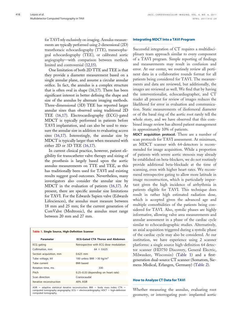
valves, the CT data are typically evaluated in asimilar fashion. All data are transferred to an offlinepost-processing workstation (such as AdvantageWorkstation 4.4, General Electric), and analysesare performed using dedicated software (such asCardIQ X-Press, General Electric). The data areloaded into a standard multiplanar cardiac reformatpackage with images reconstructed in the coronal,sagittal, and transverse (axial) orientation, and thenanalyzed using a multiplanar oblique tool. By con-vention, we begin the post-processing and analysisin the coronal plane with an axial cutplane rotatedin an anticlockwise direction so that the line runsfrom a right caudal to a left cranial position. Afterensuring that the various imaging planes are locked,attention is turned to the sagittal reconstruction,which is vertically oriented so as to be orthogonal tothe long axis of the aortic annulus. At this point, thehorizontal line representing the axial cutplane is
Figure 2. Reconstructing a Double Oblique Transverse Image of
(A) On a coronal projection of the aortic root, a vertically orient obascending aorta. (B) A transverse or axial cut-plane is placed on the(C) This transverse cut-plane yields a double oblique transverse imauntil the most caudal attachments of the aortic valve are identifiedverse image to ensure the appropriate plane for assessment of the
mum) dimensions can be obtained.moved up or down on either the sagittal or coronalprojection so as to create a double oblique transverse oraxial image of the aortic root. This horizontal line ispulled down through the root of the aorta until the
sal Ring
tool is placed to produce a sagittal oblique reconstruction of theittal reconstruction at the level of the aortic valve hinge point.of the aortic root. (D) The dataset is then scrolled up or downportantly, the nadir of all 3 cusps must be identified on 1 trans-ic annulus. At this point, both short (minimum) and long (maxi-
Table 2. Dual-Source CT-Scanner
ParameterECG-Gated CTA
ThoraxA
ECG gating Retrospective ECG gating
Collimation, mm 2.0 � 32.0 � 0.6
Section acquisition, mm 2.0 � 64.0 � 0.6
Tube voltage, kV 120
Tube current–time product,mAs per rotation
320 160
Rotation time, ms 330
Pitch 0.2–0.43
Scan direction Craniocaudal
Abbreviations as in Table 1.
Ba
liquesagge. Imaort
ortoiliac CTA BelowDiaphragm
Helical nongated
32.0 � 0.6
64.0 � 0.6
120
240
330
0.7
Craniocaudal

J A C C : C A R D I O V A S C U L A R I M A G I N G , V O L . 4 , N O . 4 , 2 0 1 1
A P R I L 2 0 1 1 : 4 1 6 – 2 9
Leipsic et al.
Multidetector Computed Tomography in TAVI
420
most caudal attachments of the 3 aortic leaflets areidentified. Importantly, to define the basal ring andprovide accurate measurements, the plane must bebalanced so that all 3 leaflets come in to view whenscrolling cephalad at the same time. If this is not thecase, the CT physician must alter the angle of theoblique tools in either the sagittal plane or coronalplane. When the inferior aspect of all 3 aortic cusps areidentified in the same plane, a true double obliquetransverse image of the root has been achieved, andthe correct plane for the majority of measurementsgermane to TAVI has been obtained (Fig. 2).
Although CT is a robust 3D measuring tool, it isnot without limitations. The temporal resolution ofcardiac CT, particularly on single-source platforms,can result in suboptimal image quality at higher heartrates. Moreover, severe valve calcification may obscureannulus assessment, particularly the determination ofthe appropriate angle of deployment. It is imperativethat the CT interpreting physician describe theselimitations when encountered, and describe the overallimage quality as with any CT examination. At ourcenter, a comment about overall image quality and thequality of the assessment of the annulus is the firststatement in any TAVI CT report.
The Aortic Annulus: What We Have Learned andHow We Measure It
The aortic annulus is a complex 3D structure.Previous anatomic studies have well established thatthe aortic annulus is a 3-pronged coronet ratherthan a circular structure, with 3 anchor points at thenadir of each aortic cusp (18). The attachment ofthe aortic cusps is semilunar, extending throughoutthe aortic root from the left ventricle distally to thesinotubular junction. Further, the annulus is oftenoval shaped, which has been observed using both3D TEE (13) and MDCT (17,19). Tops et al. (17)reported that the annulus had an oval configurationin approximately 50% of patients evaluated forTAVI, with a mean difference between coronal andsagittal measurements of 3.0 � 1.9 mm. An ovalconfiguration of the annulus was also noted byDelgado et al. (20), who reported a significantdifference between mean coronal (25.1 � 2.4 mm)and sagittal (22.9 � 2.0 mm) measurements in 53patients with severe aortic stenosis. This oval ge-ometry of the annulus has been previously undera-ppreciated on imaging but has been well describedin the surgical literature.
There have been a number of published methods
for measurement of the aortic annulus on MDCT.Initial published reports had evaluated the annulusin a coronal and sagittal fashion (Fig. 3). Recently,the annulus has been evaluated by using a3-chamber reconstruction that replicates the para-sternal long axis acquired from TTE and TEE (19)(Fig. 4). In addition, double oblique transverseimaging orthogonal to the aortic root incorporatingthe maximal and minimal diameter measurementsof the basal ring below the hinge point of the aorticvalve cusps are taken, with some groups reporting amean of these 2 measurements (Fig. 5) (19,21). It isoften useful to include bidimensional measurementsof the basal ring as well as a 3-chamber measure-ment that most closely approximates the orientationused for TTE and TEE measurement. For all ofthese measurement techniques, the annulus is as-
Figure 3. Coronal and Sagittal Oblique Reconstruction ofAortic Root
(A) Coronal oblique reconstruction and (B) sagittal obliquereconstruction of the aortic root in an 80-year-old femalepatient with critical aortic stenosis. The arterioventricular planeor annulus is elliptical in shape, measuring 26.7 mm in the coro-nal plane and 20.4 mm on the sagittal reconstruction.
l lo
J A C C : C A R D I O V A S C U L A R I M A G I N G , V O L . 4 , N O . 4 , 2 0 1 1
A P R I L 2 0 1 1 : 4 1 6 – 2 9
Leipsic et al.
Multidetector Computed Tomography in TAVI
421
sessed at the lowest hinge point of the aortic valveleaflets at the virtual basal plane. Measurements aretaken from systolic phase reconstructions rangingfrom 20% to 45% of the R-R interval, using thephase with maximum valve opening, as is per-formed using echocardiography.
Regardless of the methods used, the absolutedifferences between MDCT and TTE or TEE aregreater than the differences between TEE and TTE(19). These differences may have significant clinicalimplications. Messika-Zeitoun et al. (19) haveshown that MDCT would have influenced ormodified the TAVI strategy in 38% of patientsusing long-axis and short-axis diameters, and in42% of patients using the 3-chamber projection.These differences in absolute measurements be-tween the modalities often results in confusion
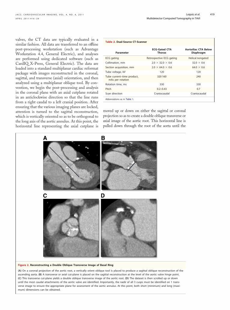
Figure 4. Annulus Assessment by CT and TTE
Annulus assessment using computed tomography (CT) and transthosevere aortic stenosis and end-stage chronic obstructive pulmonaryannulus diameter of 19.0 mm and (B) the corresponding parasterna
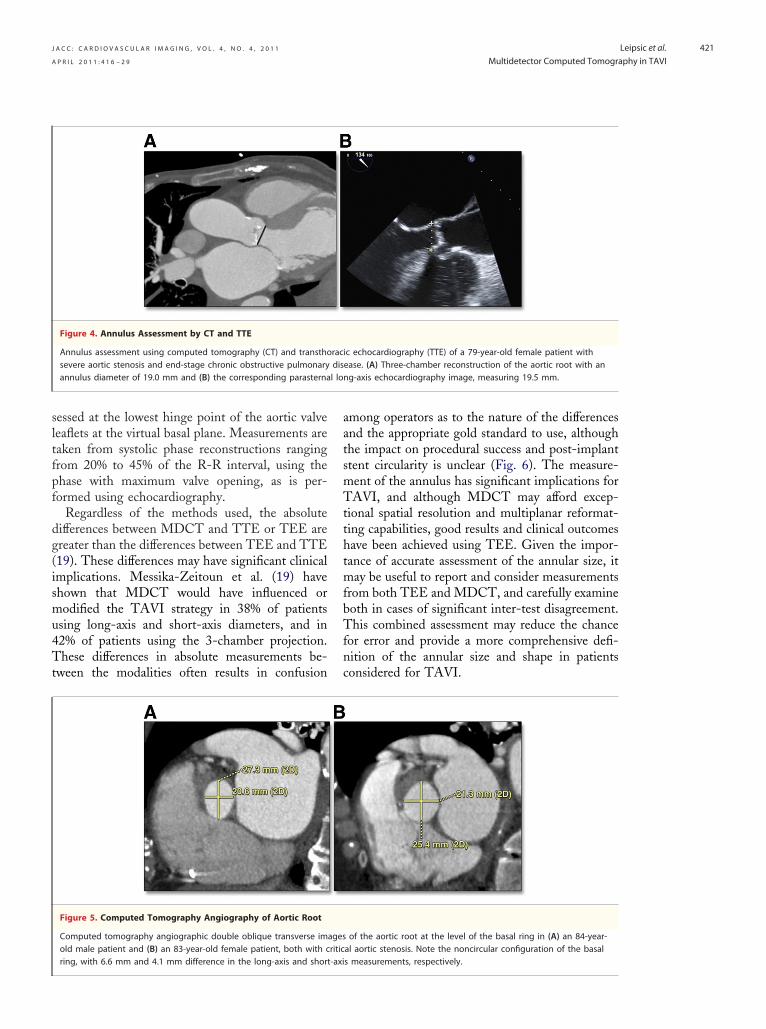
Figure 5. Computed Tomography Angiography of Aortic Root
Computed tomography angiographic double oblique transverse imold male patient and (B) an 83-year-old female patient, both with c
ring, with 6.6 mm and 4.1 mm difference in the long-axis and short-axiamong operators as to the nature of the differencesand the appropriate gold standard to use, althoughthe impact on procedural success and post-implantstent circularity is unclear (Fig. 6). The measure-ment of the annulus has significant implications forTAVI, and although MDCT may afford excep-tional spatial resolution and multiplanar reformat-ting capabilities, good results and clinical outcomeshave been achieved using TEE. Given the impor-tance of accurate assessment of the annular size, itmay be useful to report and consider measurementsfrom both TEE and MDCT, and carefully examineboth in cases of significant inter-test disagreement.This combined assessment may reduce the chancefor error and provide a more comprehensive defi-nition of the annular size and shape in patientsconsidered for TAVI.
ic echocardiography (TTE) of a 79-year-old female patient withease. (A) Three-chamber reconstruction of the aortic root with anng-axis echocardiography image, measuring 19.5 mm.
of the aortic root at the level of the basal ring in (A) an 84-year-al aortic stenosis. Note the noncircular configuration of the basal
racdis
agesritic
s measurements, respectively.

J A C C : C A R D I O V A S C U L A R I M A G I N G , V O L . 4 , N O . 4 , 2 0 1 1
A P R I L 2 0 1 1 : 4 1 6 – 2 9
Leipsic et al.
Multidetector Computed Tomography in TAVI
422
Figure 6. Double Oblique Transverse Reconstruction of Aortic Root
(A) Double oblique transverse reconstruction of the aortic root below the commissural insertion in an 87-year-old female patient with aorticstenosis being evaluated for transcatheter aortic valve replacement. The annulus is rather elliptical, with a long-axis measurement of 27.6 mm
and short-axis measurement of 22.9 mm. (B) Despite the elliptical configuration, the post-implantation examination shows a circular valve deployment.Figure 7. How to Generate a 3-Chamber Reconstruction
Multiplanar image reconstruction of a gated computed tomography angiogram in an 85-year-old male with severe symptomatic aortic stenosisfor the evaluation of the aortic root and annulus. (A) The transverse image is bisected with an oblique tool through the mitral valve to the ven-tricular apex, resulting in the formation of a vertical long-axis reconstruction. (B) The left ventricle is then cut in a plane from the left atriumthrough the center of the mitral valve through the left ventricular apex, (C) resulting in a relative 4-chamber projection. (D) An oblique tool is thenused rotated in a perpendicular fashion to the interventricular septum so as to create a short-axis projection. (E) Finally, a cut-plane is placed in an
oblique fashion at the base of the short-axis projection out the left ventricular outflow tract and aorta to create a 3-chamber projection.
J A C C : C A R D I O V A S C U L A R I M A G I N G , V O L . 4 , N O . 4 , 2 0 1 1
A P R I L 2 0 1 1 : 4 1 6 – 2 9
Leipsic et al.
Multidetector Computed Tomography in TAVI
423
Annulus Sizing: How We Do It
Multidetector CT angiography produces imagingdata that is isotropic in that it can be reconstructedin any 2D imaging plane, including those typicallyused in TTE such as the 3-chamber view (Fig. 7).These measurements, not surprisingly, seem tocorrelate best with the corresponding ECG mea-surements, which is enticing as valve sizing andpatient screening has largely been done using TTEand TEE. In using these 2D measurements, how-ever, much of the valuable and unique data availablefrom CT is ignored. In our experience, these 2Dmeasurements are also not particularly reproducibleacross readers of varying experience, and that hasthe potential to be a significant issue as TAVI
Figure 8. Aortic Root and Anatomic Location of Aortic Annulus
The 3 red rings represent the aortic valve cusps, with the greencircle placed at the nadir of the aortic cusps denoting the annu-lar plane. LC � left coronary cusp; NC � noncoronary cusp;RC � right coronary cusp.
Figure 9. Coronal Oblique Image From Coronary CT Angiogram
Coronal oblique image from a coronary computed tomography (CTfemale patient undergoing CT assessment before transcatheter aortcusp and left coronary ostium is 15 mm (A) and 10.8 mm (B), respe
for TAVR.expands to new centers. We have, therefore, movedaway from using CT to predict annular measure-ments on echocardiography and now focus onproviding unique 3D data in a noninvasive fashionto gain a better understanding of the aortic root andleft ventricular outflow tract geometry. To do so, werecreate the anatomic definition of the annulus onMDCT by constructing an image that is orthogonalto the root of the aorta immediately below the nadirof the aortic cusps, which provides the plane of theannulus (Fig. 8). In recreating the plane of theaortic root, a true transaxial image orthogonal tothe aortic annulus is achievable, allowing for short-axis and long-axis measurements of the basal ring.It is important that users recognize that these 2measurements will yield values that will often differ(19) from the measurements acquired using echo-cardiography, but in our experience, the mean ofthese 2 measurements appears to be the mostreproducible measure across multiple readers. Fur-thermore, these orthogonal projections provide anunderstanding of the circularity or elliptical natureof the root. These measurements are not onlyprovided to the interventional team but also repre-sentative images are reviewed in a collaborativefashion to allow for a more individualized approachfor each patient.
Important Aortic Root Measurements
Aortic measurements vary with individual valve spec-ifications. The Medtronic CoreValve has require-ments regarding the height and width of the aorticsinus and dimensions of the aorta at the sinotubularjunction, unlike the Sapien and Sapien XT, which donot. For both of the commonly used valves, thedistance between the insertion of the left coronary
giogram in (A) an 84-year-old male patient and (B) an 87-year-oldalve replacement (TAVR). The distance between the left coronaryely. A distance of 14 mm is considered adequate in most centers
) anic vctiv

chosen.
J A C C : C A R D I O V A S C U L A R I M A G I N G , V O L . 4 , N O . 4 , 2 0 1 1
A P R I L 2 0 1 1 : 4 1 6 – 2 9
Leipsic et al.
Multidetector Computed Tomography in TAVI
424
cusp and the left coronary artery ostium is an addi-tional important measurement and can be measuredfrom an oblique sagittal or coronal projection (Fig. 9).This measurement may predict patients at risk forcoronary occlusion during the TAVI procedure withdisplacement of the native leaflets and heavy leafletcalcification. At present, no definite criteria exist toexclude patients on the basis of the risk of coronaryobstruction, but an 11- to 14-mm distance cutoffrange has been proposed (22) between the coronaryostia and the leaflet insertion. At our institution, wepay careful attention to the distribution and burden ofcalcification of the aortic valve cusps. We have greaterconcern in the setting of heavily and diffusely calcifiedcusps than when the calcification is isolated calcifica-tion near the commissural insertion. We also assessthe length of the left coronary cusp and its relationshipto the height of the left main coronary ostium.
For the CoreValve (Medtronic), we provideother measurements required for device selection,namely, a measurement of the aortic sinus diameterof the aorta measured on a double oblique projec-tion as well as the sinus height and diameter of theascending aorta. A minimum trans-sinus dimensionof 27 mm is required, and the ascending aorta mustbe �43 mm in diameter.
Iliofemoral Access
In early TAVI cases, vascular complications werereported that were largely attributable to the largedevice size and significant atherosclerosis that wasoften present (10,22,23). Initial iliofemoral assess-ments were performed with single plane angiogra-phy at the time of coronary artery assessment. Incomparison, the multiplanar capabilities of MDCTallow a thorough and complete 3D assessment ofthe iliofemoral system. Kurra et al. (23) reportedthat 33% of patients with critical aortic stenosis hadunfavorable iliofemoral arteries, with 77% of thosepatients having minimal luminal diameters of �8mm. In addition to providing more elaborate 3Dreconstructions and accurate assessments of theminimal luminal diameter, MDCT can assess vesseltortuosity, burden and pattern of calcification, ex-tent of atherosclerosis, and identify other high-riskfeatures including dissections and complex ather-oma (Fig. 10). Successful implants have been com-pleted in patients with arteries of borderline sizeand moderate calcification. Circumferential and/orhorseshoe calcification in association with smallcaliber vessels or stenotic segments is considered a
contraindication to a transfemoral artery approach,Figure 10. Coronal Maximum Intensity Projection andVolume Rendered Images
Coronal maximum intensity projection and volume renderedimages, respectively, of the iliofemoral system in 2 elderly malepatients being evaluated for transcatheter aortic valve replace-ment (TAVR). Both patients have tortuous iliofemoral arteries,but have very different burdens of atherosclerotic calcification,with the first patient (A) being declined for TAVR on the basis ofthe extensive calcified plaque, the borderline arterial size, andtortuosity; whereas the second patient (B) was accepted forTAVR given the adequate arterial size and the paucity of calcifi-cation despite the vessel tortuosity. A third patient (C) has mini-mal tortuosity, but the minimal luminal diameter was 5.5 mmbilaterally, and a transapical approach for TAVI was therefore

J A C C : C A R D I O V A S C U L A R I M A G I N G , V O L . 4 , N O . 4 , 2 0 1 1
A P R I L 2 0 1 1 : 4 1 6 – 2 9
Leipsic et al.
Multidetector Computed Tomography in TAVI
425
as these may not allow the artery to expand toaccommodate the large-profile delivery catheter,and may increase the risk of arterial dissection orperforation. Early transarterial device delivery fail-
Figure 11. 3D Volume Rendered Image of IliofemoralVasculature and Boney Pelvis
Three-dimensional (3D) volume rendered image of the iliofemo-ral vasculature and boney pelvis in an 86-year-old femalepatient with severe symptomatic aortic stenosis. Modeling theboney pelvis with the arterial system provides landmarks to dis-play the site of minimal luminal diameter and to help guide thearterial puncture. In this case, the minimal diameter on the rightwas 5.2 mm (arrow) at the mid-femoral head, thereby guiding ahigher puncture.
Figure 12. Stepwise Approach to Construction of 3D Volume Re
A 3-dimensional (3D) volume rendered projection of the aorta in an 84denoting the inferior margin of the aortic cusps in a double oblique trnal projection (A), resulting in a sagittal oblique projection (B), from wby again using the workstation oblique tool. The images are reviewedprojection of the root are identified. Points are then deposited on thesmeant to overlay the inferior margin of the root (D). A 3D volume renplace. In this 84-year-old male patient, anterior posterior (AP) caudal 1triangle is no longer evident because all 3 points are in the same plan
the inferior margins of the cusps are not in the same plane, and thereforeures have been attributed in part to circumferentialiliofemoral calcification that was not appreciated onscreening calibrated angiography studies (24). Cur-rently, alternative transapical or transaxillary ap-proaches may be considered in these patients.
In our experience, a standardized approach toiliofemoral assessment yields the best results andgreatly reduces morbidity and mortality rate fromvascular injury. We incorporate a number of recon-structions into our standard iliofemoral evaluationby MDCT, including 3D volume rendered imag-ing, curved multiplanar reformats, and maximumintensity projection images. Multiple measurementsare taken along the entire course of the iliofemoralsystem bilaterally with the minimum luminal mea-surement recorded for each side and included in thereport. Identifying the specific location of areaswith reduced luminal size is important; in somecases, access can be achieved proximal to the site by acutdown approach. A moderate descriptor of theoverall plaque burden and presence of iliofemoralcalcification is noted. Particular attention is given toany regions of circumferential or horse shoe calcifica-tion. Importantly, the minimal luminal diameter isprovided along the entire course of both the right andleft iliofemoral system down to the femoral head. Weprovide annotated volume rendered images with the
red Image of Aortic Root
r-old male patient with aortic stenosis is reconstructed with pointserse reconstruction. The aorta is first bisected from a standard coro-a double oblique transverse image of the aortic root (C) is createdthe most inferior margins of the aortic cusps on the orthogonalost inferior margins and linked, thereby creating a triangle that isd image of the ascending aorta is then created with the triangle ins considered an appropriate coaxial angle (E) of deployment, as thet at AP caudal 40, the triangle is well defined (F), suggesting that
nde
-yeaansvhich, ande mdere4 wae; bu
, are an inappropriate angle for deployment.

angles from our cohor
1.5 mm ab
J A C C : C A R D I O V A S C U L A R I M A G I N G , V O L . 4 , N O . 4 , 2 0 1 1
A P R I L 2 0 1 1 : 4 1 6 – 2 9
Leipsic et al.
Multidetector Computed Tomography in TAVI
426
femoral heads in place denoting the location of themeasured minimal luminal diameter (Fig. 11).
How to Predict an Appropriate Angle ofDeployment Using CT
There is also significant potential of MDCT toassess the aortic root in relation to the body axis(21). Traditionally, standard practice has been todetermine root orientation using multiple repeatcatheter aortograms in 1 or 2 orthogonal planes
isplay of the Line of Perpendicularity
the typical caudal or cranial angulation needed at the spectrum of(RAO) to left anterior oblique (LAO) projections (5° intervals) toicularity to the X-ray beam. The diamonds denote the meant, and the bars denote the range.
. Curved Multiplanar Reformat of Left Main CoronaryAscending Aorta
ltiplanar reformat of the left main coronary artery and theaorta shows the relationship of the left main ostium and the dis-the valve in an 82-year-old male patient. The distance measured,
ove in this case, is represented by the white arrowhead.before starting the procedure. This process is con-sidered critical to ensure precise coaxial positioningof the stent along the centerline of the aorta (21), asthe valve stent needs to be deployed in a projectionthat is perpendicular to the native valve annulus.Thus, physicians performing TAVI need to choosean implant projection in which the valve is perpen-dicular or orthogonal to the native valve plane. Theneed for multiple aortograms to define this optimalorientation increases procedural time, contrast use,and radiation exposure. Further, if appropriate ori-entation is not achieved, there is a potential forinappropriate positioning of the device, and in-creased risk of procedural complications such asstent embolization (21,25).
It is understood that there are many potentialangles representing the appropriate native aorticvalve plane in any individual patient. From aortog-raphy and anatomic studies, it is known that theaortic valve is typically directed in a cranial andanterior fashion with angulation to the right. Onthe basis of this assumption, the team typically usescaudal angulation when in a right anterior oblique(RAO) projection and cranial angulation when inthe left anterior oblique (LAO) projection. How-ever, there are significant variations in patient anat-omy, and pre-procedural assessment of a patient’saortic root geometry has been shown to be benefi-cial in predicting the appropriate angle of implan-tation (21,25).
As many patients routinely have MDCT per-formed before TAVI, the dataset can be used toprovide orientation of the aortic root, which maypredict the appropriate angle of implantation. Sim-ilar to the evaluation of the aortic annulus, doubleoblique transverse multiplanar reconstructions areperformed to assess the internal diameter of theaortic annulus and root. From this projection,points are deposited on the most inferior aspect ofthe aortic sinuses, and the points are then linked toform a triangle. A 3D volume rendered reconstruc-tion of the aorta is then created with the trianglesuperimposed upon it. The reconstruction can thenbe rotated through a series of any angles (Fig. 12).At our center, we aim to find angiographic projec-tions representing perpendicularity to the nativevalve plane in 3 axes: 1) cranial-caudal with noRAO or LAO angulation; 2) straight RAO toLAO as needed with no cranial or caudal angula-tion; and 3) LAO 30° with cranial or caudalangulation as needed. These axes were chosen on
Figure 13. Graphic D
The graph representsright anterior obliqueachieve valve perpend
Figure 14Artery and
Curved muascendingtal end of
the basis of past experiences and the preferred

J A C C : C A R D I O V A S C U L A R I M A G I N G , V O L . 4 , N O . 4 , 2 0 1 1
A P R I L 2 0 1 1 : 4 1 6 – 2 9
Leipsic et al.
Multidetector Computed Tomography in TAVI
427
working angles, given the physical constraints of thecatheterization laboratory.
Pre-procedural angle prediction with MDCTmay decrease the number of aortograms requiredduring the procedure, shortening both proceduretime and contrast usage, and potentially increasesthe likelihood of coaxial implantation by optimizingthe orientation during device placement. MDCTmay be particularly helpful in patients with unusualanatomy requiring steep projections that would bedifficult to predict, as may be observed in patientswith musculoskeletal abnormalities, kyphoscoliosis,and markedly unfolded aortas. Although one mayselect 3 predicted angles of implantation, there aremany other appropriate angles for deployment. Wehave found that a “line of perpendicularity” can begenerated in each patient, where any point inthe RAO to LAO spectrum can be utilized as longas the correct amount of caudal or cranial angula-tions is added (Fig. 13).
How and Why CT Should Be Used forLong-Term Follow Up
Similar to annular sizing, deriving a double obliquetransverse projection that is orthogonal to the aorticroot is integral to evaluate transcatheter aortic valvestents. This allows for the assessment of expansion,circularity, and apposition. From a long-axis or coro-nal oblique projection, assessment of implantationdepth in relation to the native annulus and thecoronary arteries can be performed. The stents are alsointerrogated using multiplanar reformats, maximumintensity projections, and volume rendering for stentfracture.
Circularity can be defined in a number of waysboth qualitatively and quantitatively. We typicallyuse an eccentricity index (26), using a simpleformula derived from measurements on the doubleoblique projections: (1�Dmin/Dmax), whereDmin and Dmax are 2 perpendicular diametersrepresenting the smallest and largest external diam-eters at each level. We will typically do this analysisat 3 levels, spanning from the most ventricular(inferior) margin of the stent through to the aortic(upper) end. We consider a circular deployment aneccentricity index of �0.1 (26).
Implantation depth is evaluated on a coronaloblique reconstruction meant to display the inferiormargin of the stent, the position of the left maincoronary artery, and the floor of the sinuses of Val-salva. Measurements are taken from the floor of the
sinus on the coronal plane to the inferior margin of thestent, as well as the distance from the outer border ofthe frame to the coronary ostium (Fig. 14), with thedistance considered positive if there was coronaryoverlap and negative if the superior margin of the stentwas below the left main. The meaning of a change inthis final measurement is not certain, but is beingevaluated as a potential means to assess for stentmigration.
Figure 15. Coronal Oblique Reformat and 3DImage of Ascending Aorta
(A) Coronal oblique reformat and (B) 3-dimensional (3D) volumerendered image of the ascending aorta in an 86-year-old malepatient �4 years after transcatheter aortic valve replacement(TAVR) with an Edwards Sapien valve in situ. Note the positionof the stent, the absence of in-stent stenosis, and the integrity
of the valve stent struts.
J A C C : C A R D I O V A S C U L A R I M A G I N G , V O L . 4 , N O . 4 , 2 0 1 1
A P R I L 2 0 1 1 : 4 1 6 – 2 9
Leipsic et al.
Multidetector Computed Tomography in TAVI
428
Clinical and hemodynamic follow-up is nowavailable �5 years after TAVI. MDCT can furtherevaluate these cases for valve durability (both leafletand stent), lack of coaptation of the stent to theannulus suggestive of paravalvular regurgitation,and stent migration. Although the value of post-procedural evaluation of these patients remainsuncertain (27), MDCT may certainly be useful inassessing these valves and add valuable incrementalinformation. We have evaluated 21 patients at least3 years after TAVI with MDCT. In this cohort,there were no stent fractures or visible leafletthickening (Fig. 15). The valve stent leaflets werefree of calcification or fusion, and there was noevidence of thrombus in the aortic sinus (28). Eightpatients had MDCT scans immediately post-procedure and again after at least 3 years, allowingfor serial comparisons. There was no evidence ofstent migration detected as measured by the dis-tance from the top of the stent to the origin of theleft main coronary artery ostium. There was nosignificant stent recoil or decrease in diameter at thelevel of the annulus, but there was a trend towardreduction in stent diameter in the aortic side of thestent. This is not entirely unexpected as the aorticend tends to preferentially dilate as the annular endis confined by the fabric skirt of the Edwards Sapienvalve. The lack of stent recoil at the level of theannulus is reassuring, because it would be at theannular level that the stent leaflets would be com-pressed and potentially compromised by stent re-
aortic valve by the left ventricular Transapical minim
also suggesting appropriate valve function, withstable aortic valve area and gradients. Future studiesmay be warranted in larger cohorts. Importantly,while there are growing follow-up data for TAVIwith CT, there is no defined role at present for theroutine clinical use of CT for TAVI follow-up inpatients without evidence of perivalvular regurgita-tion on echocardiography.
Conclusions
Therapy with TAVI has seen rapid advancementsover the last 5 years and is now being performed atmany centers with good clinical outcomes. Echo-cardiography has been the most commonly usedtool for pre-procedural assessment and providesphysiologic data; however, MDCT can evaluate 3Dannular and aortic root morphology and dimen-sions, which may supplement data provided byechocardiography, in addition to additional assess-ment of iliofemoral access by MDCT. Continuingdevelopment of devices and the utilization of ad-vanced imaging tools such as MDCT continue toimprove the safety and potential application ofTAVI in the management of symptomatic aorticstenosis.
Reprint requests and correspondence: Dr. Jonathon Leipsic,Department of Medical Imaging, St. Paul’s Hospital, 1081Burrard Street, Vancouver, British Columbia V6S 1Y6,
coil. These patients had echocardiographic findings Canada. E-mail: [email protected].
1
1
1
R E F E R E N C E S
1. Nkomo VR, Gardin JM, Skelton TN,et al. Burden of valvular heart diseases.Lancet 2006;368:1005–11.
2. Bonow RO, Carabello BA, Kanu C,et al. ACC/AHA 2006 guidelines forthe management of patients with val-vular heart disease: a report of theAmerican College of Cardiology/American Heart Association TaskForce on Practice Guidelines (WritingCommittee to Revise the 1998 Guide-lines for the Management of PatientsWith Valvular Heart Disease). J AmColl Cardiol 2006;48:e1–148.
3. Iung B, Baron G, Butchart EG, et al.Prospective survey of patients withvalvular heart disease in Europe. EurHeart J 2003;24:1231–43.
4. Svensson LG, Dewey T, Kapadia S, etal. United States feasibility study oftranscatheter insertion of a stented
apex. Ann Thorac Surg 2008;86:46–55.
5. Walther T, Falk V, Kempfert J, et al.Transapical minimally invasive aorticvalve implantation: the initial 50 pa-tients. Eur J Cardiothorac Surg 2008;33:983–8.
6. Grube E, Schuler G, Buellesfeld L,et al. Percutaneous aortic valve re-placement for severe aortic stenosisin high-risk patients using thesecond- and current third-generationself-expanding CoreValve prosthesis:device success and 30-day clinical out-come. J Am Coll Cardiol 2007;50:69–76.
7. Webb JG, Pasupati S, Humphries K,et al. Percutaneous transarterial aorticvalve replacement in selected high-risk patients with aortic stenosis. Cir-culation 2007;116:755–63.
8. Walther T, Simon P, Dewey T, et al.
ally invasive aorticvalve implantation: multicenter expe-rience. Circulation 2007;116:I240–5.
9. Leon MB, Smith CR, Mack M, et al.Transcatheter aortic-valve implanta-tion for aortic stenosis in patients whocannot undergo surgery. N EnglJ Med 2010;363:1597–607.
0. Webb JG, Chandavimol M, Thomp-son CR, et al. Percutaneous aorticvalve implantation retrograde fromthe femoral artery. Circulation 2006;113:842–50.
1. Ye J, Cheung A, Lichtenstein SV, etal. Transapical aortic valve implanta-tion in humans. J Thorac CardiovascSurg 2006;131:1194–6.
2. Grube E, Laborde JC, Gerckens U, etal. Percutaneous implantation of theCoreValve self-expanding valve pros-thesis in high-risk patients with aorticvalve disease: the Siegburg First-In-Man study. Circulation 2006;114:
1616–24.
1
2
2
2
2
2
J A C C : C A R D I O V A S C U L A R I M A G I N G , V O L . 4 , N O . 4 , 2 0 1 1
A P R I L 2 0 1 1 : 4 1 6 – 2 9
Leipsic et al.
Multidetector Computed Tomography in TAVI
429
13. Al Ali AM, Altwegg L, Horlick EM,et al. Prevention and management oftranscatheter balloon-expandable aor-tic valve malposition. Catheter Car-diovasc Interv 2008;72:573–8.
14. Tuzcu ME. Transcatheter aortic valvereplacement malposition and emboli-zation: innovation brings solutionsalso new challenges. Catheter Cardio-vasc Interv 2008;72:579–80.
15. Moss RR, Ivens E, Pasupati S, et al.Role of echocardiography in percuta-neous aortic valve implantation. J AmColl Cardiol Img 2008;1:15–24.
16. Ng A, Delgado V, van der Kley F, etal. Comparison of aortic root dimen-sions and geometries before and aftertranscatheter aortic valve implantationby 2- and 3-dimensional transesoph-ageal echocardiography and multislicecomputed tomography. Circ Cardio-vasc Imaging 2010;3:94–102.
17. Tops LF, Wood DA, Delgado V, etal. Noninvasive evaluation of the aor-tic root with multislice computed to-mography. Implications for transcath-eter aortic valve replacement. J AmColl Cardiol Img 2008;1:321–30.
18. Anderson RH, Lal M, Ho SY. Anat-omy of the aortic root with particularemphasis on options for its surgicalenlargement. J Heart Valve Dis 1996;
Suppl 3:249–57.9. Messika-Zeitoun, Serfaty Jean-Michel,Brochet E, et al. Multimodal assess-ment of the aortic annulus diameter.J Am Coll Cardiol 2010;55:186–94.
0. Delgado V, Ng AC, van de Veire NR,et al. Transcatheter aortic valve im-plantation: role of multi-detector rowcomputed tomography to evaluateprosthesis positioning and deploy-ment in relation to valve function. EurHeart J 2010;31:1114–23.
1. Kurra V, Kapadia S, Tuzcu M, et al.Pre-procedural imaging of aortic rootorientation and dimensions comparisonbetween X-ray angiographic planar im-aging and 3-dimensional multidetectorrow computed tomography. J Am CollCardiol Intv 2010;3:105–113.
2. Jean-Bernard Masson, Jan Kovac, Ger-hard Schuler, et al. Transcatheter aorticvalve implantation: review of the nature,management, and avoidance of proce-dural complications. J Am Coll CardiolIntv 2009;2:811–20.
3. Kurra V, Schoenhagen P, Roselli EE, etal. Prevalence of significant peripheralartery disease in patients evaluated forpercutaneous aortic valve insertion: pre-procedural assessment with multidetec-tor computed tomography J ThoracCardiovasc Surg 2009;137:1258–64.
4. Descoutures F, Himbert D, Lepage L,
et al. Contemporary surgical or percu-taneous management of severe aorticstenosis in the elderly. Eur Heart J2008;29:1410–7.
25. Gurvitch R, Wood D, Leipsic J, etal. Multislice computed tomographyfor prediction of optimal angio-graphic deployment projections dur-ing transcatheter aortic valve im-plantation. J Am Coll Cardiol Intv2010;3:1157– 65.
26. Delgado V, Ng AC, van de Veire NR,et al. Transcatheter aortic valve im-plantation: role of multidetector rowcomputed tomography to evaluateprosthesis positioning and deploy-ment in relation to valve function. EurHeart J 2010;31:1114–23.
27. Wood DA, Tops LF, Mayo JR, et al.Role of multislice computed tomogra-phy in transcatheter aortic valve re-placement. Am J Cardiol 2009;103:1295–301.
28. Gurvitch R, Wood DA, Tay EL, et al.Transcatheter aortic valve implanta-tion. Durability of clinical and hemo-dynamic outcomes beyond 3 years in alarge patient cohort. Circulation2010;122:1319–27.
Key Words: aortic stenosis ycardiac CT y transcatheter
aortic valve implantation.