from analysis model to software architecture: a pim2pim
TRANSCRIPT

From Analysis Model to Software Architecture: A PIM2PIM Mapping
Jorge Enrique Perez-Martinez and Almudena Sierra-Alonso
Abstract. To our knowledge, no current software development methodology explicitly describes how to transit from the analysis model to the software architecture of the application. This paper presents a method to derive the software architecture of a system from its analysis model. To do this, we are going to use MDA. Both the analysis model and the architectural model are PIMs described with UML 2. The model type mapping designed consists of several rules (expressed using OCL and natural language) that, when applied to the analysis artifacts, generate the software architecture of the application. Specifically the rules act on elements of the UML 2 metamodel (metamodel mapping). We have developed a tool (using Smalltalk) that permits the automatic application of these rules to an analysis model defined in Rose to generate the application architecture expressed in the architectural style C2.
1 Introduction
It is well known that the development (and maintenance) of software applications is a very complex task. Software development methodologies ([1], [2], [3], [4], [7]) were proposed as tools to decrease complexity, by providing methods to elaborate each aspect involved in the application development. However, the weakest link in all those methodologies is the transition between phases: there are no established methods indicating what to do with the software artifacts generated in one step when moving to the next one. This deficiency is more evident in the transition from the analysis phase to the software architecture development [6].
With regard to the development paradigm based on model, in which MDA (Model Driven Architecture) is supported, permits to transform the software artifacts of a phase development defined in a source model, in other software artifacts that establish the target model. To do that transformation it is necessary to define a mapping; that is, a "specification of a mechanism for transforming the elements of a model conforming to a particular metamodel into elements of another model that conforms to another (possibly the same) metamodel" [10].
This work presents a proposal that enables the transition from the software artifacts generated by the analysis activity to the elements forming the resulting architecture.

To do so, we have designed a mapping that, when applied to the analysis model, generate the software architecture of the application. Both models (analysis and software architecture) are described in UML 2 ([11], [13], [14], [15]). The rules that define the mapping function operate over the UML 2 metamodel. To help this transition we have built a tool that, when given an analysis model (in Rational Rose™), and by the application of the rules of mapping, generates the software architecture of the application for the C2 architectural style [8].
The paper is organized as follows. Sections 2 and 3 characterize the elements that appear in the analysis model (source model) and in the software architecture (target model) respectively. Section 4 presents the mapping rules that permit to transform a PIM (the analysis model) into another PIM (software architecture). In Section 5 we present a tool to automate this mapping. Finally, in Section 6 we present the main conclusions of this work and some related future work.
2 Source Model: The Analysis Model
The set of artifacts generated in the analysis activity forms the analysis model. The analysis activity we are referring to is the use-case analysis as described in [7]. This analysis activity implies the analysis of the use-cases, the analysis of the classes and packages and the architectural analysis. We do not take into account this last aspect since this work proposes to obtain automatically the architecture from the analysis model. Therefore, this analysis activity is different from the analysis activity described, for example, in [20], where this activity focuses on: analyzing the consistency and completeness of requirements (defined in a software requirements document), negotiating the requirements (if there are conflicts), prioritizing the requirements, analyzing technical viability and costs to realize those requirements, etc. Therefore, the analysis activity is performed over the use case model obtaining the analysis model. Analysis artifacts include the analysis classes, use-case realization-analysis, analysis packages, and special requirements. Furthermore, we will use some stereotypes defined in Rational Unified Process, RUP (a specialization from [7]) to characterize analysis classes: «boundary» , « c o n t r o l » and « e n t i t y » . The set of artifacts generated in the analysis activity, and expressed in UML, is shown in Figure 1.
3 Target Model: An UML 2 Profile for C2 Architectural Style
In [19] we can read: "Abstractly, software architecture involves the description of elements from which systems are built, interactions among those elements, patterns that guide their composition, and constraints on these patterns." Now, we briefly describe the C2 architectural style. "The C2 architectural style can be informally summarized as a network of concurrent components hooked together by message routing devices" [8]. A fundamental aspect of this style is the principle of limited visibility or substrate independence, that is, a component only knows the components on top of it. Every component has its own control flow and no assumptions are made about the existence of a shared addressing space.

Analysis Class
A Use-case
Realization-Analysis
o <>
Class Diagram Interaction Diagram
Boundary Control Class Class
Entity Class
Collaboration Diagram
Fig. 1. Elements in the analysis model
The key elements of the C2 architecture are components and connectors. Components communicate through asynchronous message passing. Messages consist of a name and a set of associated typed arguments. There are two types of messages: notifications and requests. Notifications are announcements of changes in the state of the internal object of a component. Requests sent by a component indicate service requests to components on top of it. A notification is always sent downward through a C2 architecture while a request is always sent up. Both components and connectors must have top and bottom domains. The top domain of a component specifies the set of notifications to which the component responds and the set of requests that can be sent by the component. The bottom domain specifies the set of notifications that can be sent by the component and the set of requests to which it responds. The top domain of a component can only be connected to the bottom domain of a connector and its bottom domain can only be connected to the top domain of a connector. A connector can be connected to any number of components and/or connectors. Components can only communicate through connectors since direct communication between components is forbidden. Two connectors can only be connected from the bottom of one to the top of the other. Connectors are responsible for routing and, potentially, multicasting messages. A secondary responsibility of connectors is message filtering. Connectors can provide the following policies for filtering and delivery of messages: no filtering, notification filtering, message filtering, prioritized, and message sink.
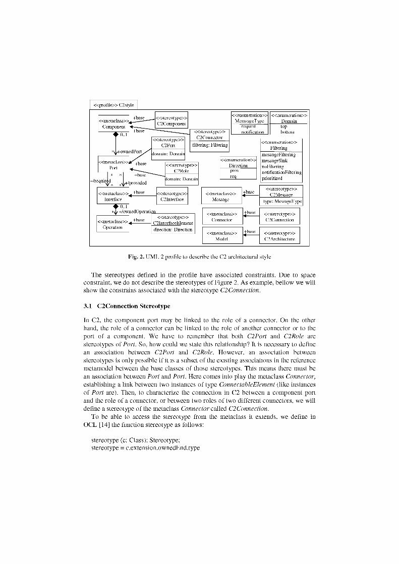
As [17] says, UML 2 cannot represent some elements of a software architecture. For example, UML 2 cannot represent the software connector of the C2 style [18]. Because of this, in this work we have defined a UML 2 profile to represent the C2 architectural style (Figure 2).
« p r o f i l e » C2style
« e n u m er a t i o n » MesssageType
«enumera t ion» Domain
request notification
top bottom
« e n u m er a t i o n » Filtering
messageFiltering messages ink noFiltering notificationFiltering prioritized
« s t e r e o t y p e » C2InterfaceElement direction: Direction
« m e t a c l a s s » Message
+base « s t e r e o t y p e » C2Message « m e t a c l a s s »
Message
« s t e r e o t y p e » C2Message « m e t a c l a s s »
Message type: MessageType
« m e t a c l a s s » Connector
+base « s t e r e o t y p e » C2Connection
« m e t a c l a s s » Connector
« s t e r e o t y p e » C2Connection
« m e t a c l a s s » Model
+base <
« s t e r e o t y p e » C2Architecture
Fig. 2. UML 2 profile to describe the C2 architectural style
The stereotypes defined in the profile have associated constraints. Due to space constraint, we do not describe the stereotypes of Figure 2. As example, bellow we will show the constrains associated with the stereotype C2Connection.
3.1 C2Connection Stereotype
In C2, the component port may be linked to the role of a connector. On the other hand, the role of a connector can be linked to the role of another connector or to the port of a component. We have to remember that both C2Port and C2Role are stereotypes of Port. So, how could we state this relationship? It is necessary to define an association between C2Port and C2Role. However, an association between stereotypes is only possible if it is a subset of the existing associations in the reference metamodel between the base classes of those stereotypes. This means there must be an association between Port and Port. Here comes into play the metaclass Connector, establishing a link between two instances of type ConnectableElement (like instances of Port are). Then, to characterize the connection in C2 between a component port and the role of a connector, or between two roles of two different connectors, we will define a stereotype of the metaclass Connector called C2Connection.
To be able to access the stereotype from the metaclass it extends, we define in OCL [14] the function stereotype as follows:
stereotype (c: Class): Stereotype; stereotype = c.extension.ownedEnd.type
In the context of this stereotype (C2Connection) we define the following constraints (also in OCL):
[1] A connection in C2 links two elements, self.base.end -> size() = 2
[2] A connection in C2 links a component port with a connector role or two roles of two different connectors. let ports: Set = self.base.end -> select (ell stereotype(el.role).name = 'C2Port') let roles: Set = self base.end -> select (ell stereotype(el.role).name = 'C2Role') in
ports -> size() = 1 implies roles -> size() = 1 and roles -> size() = 2 implies roles -> forAll (rl r2l rl.end <> r2.end)
[3] A connection in C2 cannot link two ports. let ports: Set = self.base.end -> select (ell stereotype(el.role).name = 'C2Port') in not ports -> size() = 2
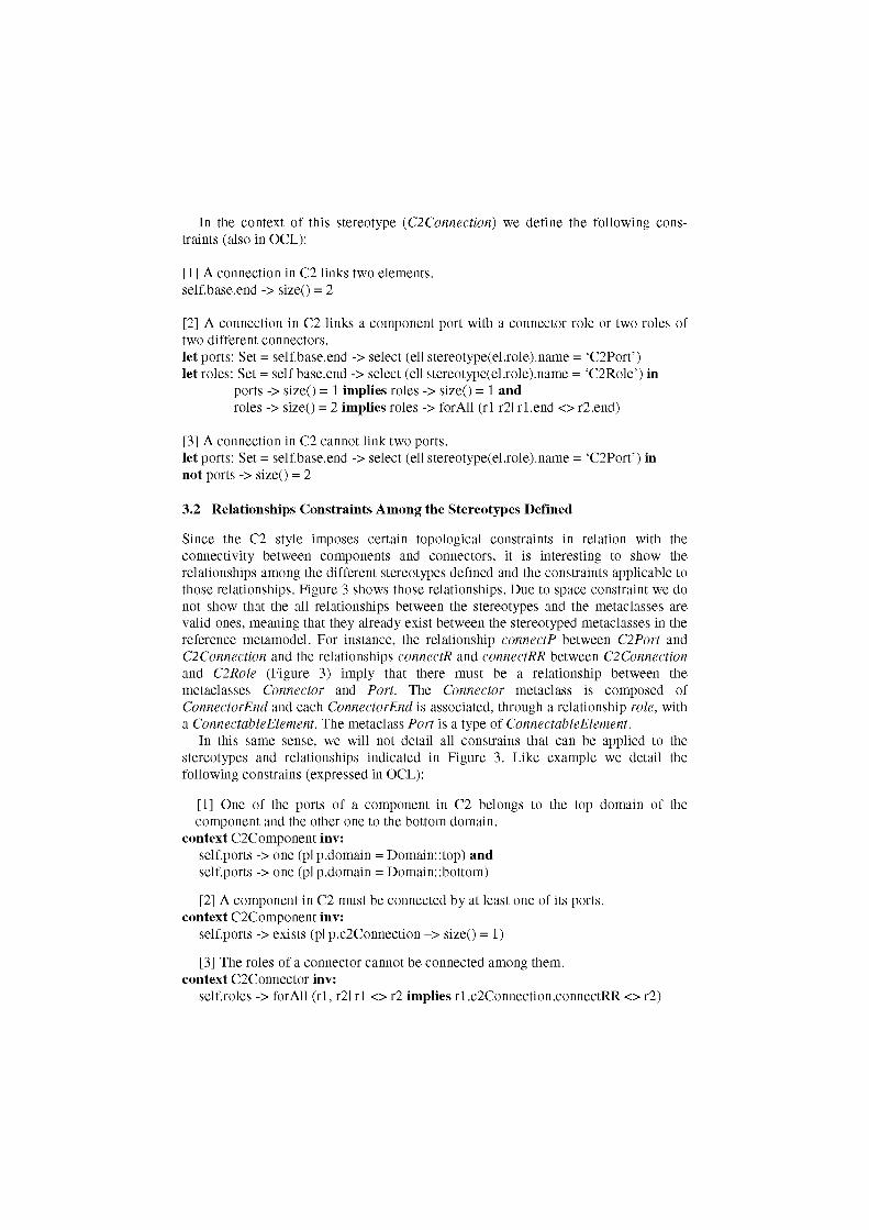
3.2 Relationships Constraints Among the Stereotypes Defined
Since the C2 style imposes certain topological constraints in relation with the connectivity between components and connectors, it is interesting to show the relationships among the different stereotypes defined and the constraints applicable to those relationships. Figure 3 shows those relationships. Due to space constraint we do not show that the all relationships between the stereotypes and the metaclasses are valid ones, meaning that they already exist between the stereotyped metaclasses in the reference metamodel. For instance, the relationship connectP between C2Port and C2Connection and the relationships connectR and connectRR between C2Connection and C2Role (Figure 3) imply that there must be a relationship between the metaclasses Connector and Port. The Connector metaclass is composed of ConnectorEnd and each ConnectorEnd is associated, through a relationship role, with a ConnectableElement. The metaclass Port is a type of ConnectableElement.
In this same sense, we will not detail all constrains that can be applied to the stereotypes and relationships indicated in Figure 3. Like example we detail the following constrains (expressed in OCL):
[1] One of the ports of a component in C2 belongs to the top domain of the component and the other one to the bottom domain.
context C2Component inv: self.ports -> one (pi p.domain = Domain::top) and self.ports -> one (pi p.domain = Domain::bottom)
[2] A component in C2 must be connected by at least one of its ports. context C2Component inv:
self.ports -> exists (pi p.c2Connection -> size() = 1)
[3] The roles of a connector cannot be connected among them. context C2Connector inv:
self.roles -> forAll (rl, r2l rl <> r2 implies rl.c2Connection.connectRR <> r2)

•^4
_M
hasComp
« s t e r e o t y p e » C2Architecture
« s t e r e o t y p e » C2Component
operations
« m e t a c l a s s » Operation
« m e t a c l a s s » Property
ports j , 2
1 « s t e r e o t y p e »
C2Connector
filtering: Filtering
« s t e r e o t y p e » C2Port
domain: Domain
« m e t a c l a s s » Constraint
^ / O . . ! 0..1 JnterfaceProv
« s t e r e o t y p e » C2Interface
« s t e r e o t y p e » C21nterfaceElement
direction: Direction
« s t e r e o t y p e » C2Connection
flow
{ordered}
« s t e r e o t y p e » C2Message
type: MessageType
T roles 1..*
« s t e r e o t y p e » C2Role
domain: Domain
Fig. 3. Abstract syntax to represent the C2 architectural style
[4] If the port of the top domain of a component is connected, it must be with the role in the bottom domain of a connector.
context C2Port inv: self.domain = Domain::top and self.c2Connection.connectR -> size() = 1 implies self.c2Connection.connectR.domain = Domain: :bottom
4 Mapping
Before describing the mapping rules we want to clarify why in this work we talk about a PIM to PIM transformation instead of PIM to PSM (as it is habitual). From our point of view, the architectural model expressed in the architectural style C2 is a PIM. This model will be transformed in a PSM when the implementation platform is selected. We think that the description of the software architecture of an application should be independent of the execution platform. Furthermore, to implement an architecture, heterogeneous platforms (software and hardware) are usually used. We only could consider that the architectural model in C2 is a PSM if it is supported by a platform that implements the C2 style (like ArchStudio 3.0). This platform [5] implements (among others) the component and the connector types specify in C2. In any case, as it is indicated in [10] "what counts as a platform is relative to the purpose of the modeller".
4.1 Characteristics of the Mapping
The transformation proposed in this work can be characterized from four orthogonal viewpoints:
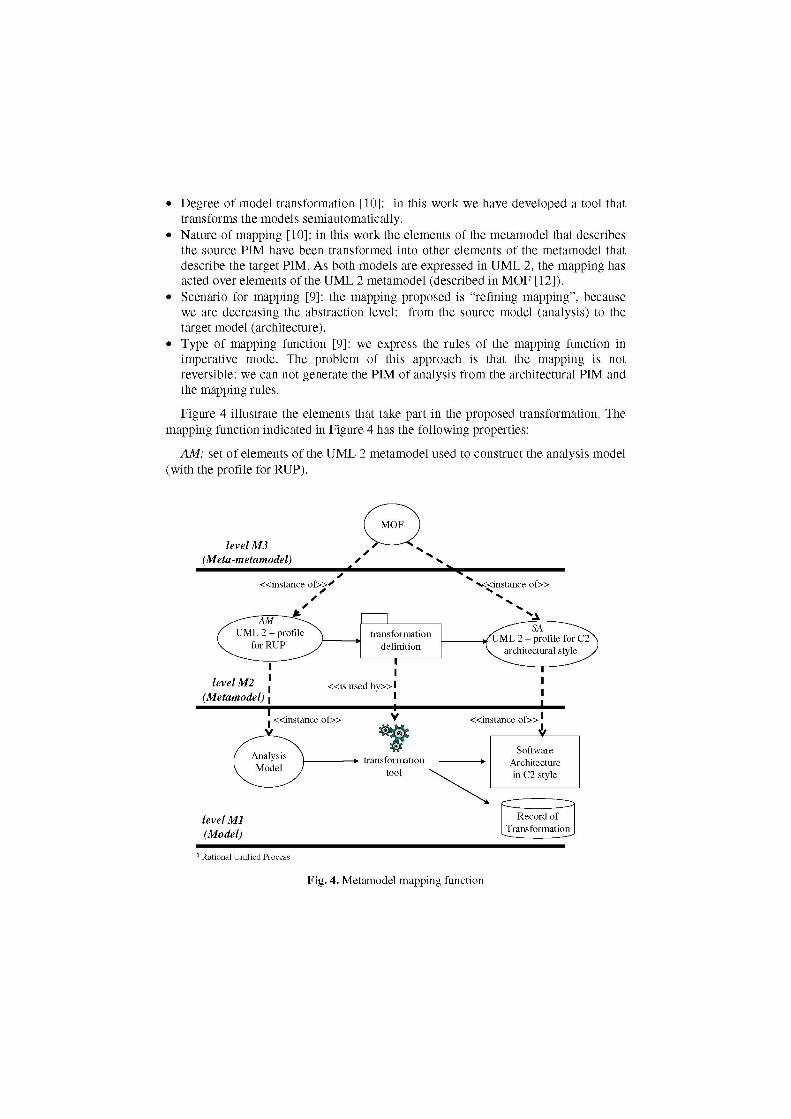
• Degree of model transformation [10]: in this work we have developed a tool that transforms the models semiautomatically.
• Nature of mapping [10]: in this work the elements of the metamodel that describes the source PIM have been transformed into other elements of the metamodel that describe the target PIM. As both models are expressed in UML 2, the mapping has acted over elements of the UML 2 metamodel (described in MOF [12]).
• Scenario for mapping [9]: the mapping proposed is "refining mapping", because we are decreasing the abstraction level: from the source model (analysis) to the target model (architecture).
• Type of mapping function [9]: we express the rules of the mapping function in imperative mode. The problem of this approach is that the mapping is not reversible: we can not generate the PIM of analysis from the architectural PIM and the mapping rules.
Figure 4 illustrate the elements that take part in the proposed transformation. The mapping function indicated in Figure 4 has the following properties:
AM: set of elements of the UML 2 metamodel used to construct the analysis model (with the profile for RUP).
level M3 (Meta-metamodel)
Q «instance of»<' >«instance o f »
level Ml (Model)
1 Rational Unified Process
Fig. 4. Metamodel mapping function

SA: set of elements of the UML 2 metamodel extended (with the profile for C2) used to construct the architectural model.
3f: AM -> SA |
(f(x) = yAf(x') = y)=>x = x ' . (1)
3x 6 AM A Vy 6 SA =e> (x, y) g= f. (2)
3y 6 SA A Vx 6 AM ^> (x, y) g= f. (3)
Firstly we have to observe the function is unidirectional: from the analysis model to architectural model. This one involves that it is not possible obtain the analysis model from architectural model and the transformation rules. This constraint comes from the imperative nature of the mapping rules.
The expression (1) that indicates the function f is injective. The expression (2) indicates that not every element of the analysis model turns into an architectural model; that is, not every artifact generates during the analysis activity is significant to the architecture. For example: the association names or association roles. The expression (3) indicates that there are architectural elements that cannot associate with any analysis element; for example port and role. These elements are intrinsic to the architectural style.
4.2 Mapping Rules
We have designed 32 rules but, due to space constraint, we will only include here 9 of them. The rules have been expressed in natural language and OCL while waiting for MOF QVT [16] becomes an "Available Specification" (now is an "Adopted Specification"). The rules presented here deal with some aspects of the analysis classes, their attributes and operations, and some aspects of the collaboration diagrams. However, we have designed more rules to deal with different modelling aspects that can appear in the analysis, like inheritance, aggregations, compositions, abstract classes, class invariants, preconditions and postconditions on operations, analysis packages, association classes, class variables, etc.
To be able to define constraints on a stereotype that will apply to the metaclass that it extends or to any of its relations, we name base the association end (see Figure 2). From here we consider that:
let clas: Set (Class) = PIM_AM -> select (e I e.oclIsTypeOf (Class)) let comp: Set (Component) = PIM_SA -> select (e I e.oclIsTypeOf (C2Component))
PIM_AM is the analysis model and PIM_SA is the architectural model. The formal expression en every rule is described in OCL.
1) A concrete analysis class is transformed into a C2 component with the same name. This component is simple, which means that it does not contain other architectural elements. This transformation is based on the idea that both elements have similar abstraction levels: an analysis class represents an entity in the problem

domain while a component represents an independent element in the solution domain. However, when composition relationships exist among several analysis classes, these classes can be combined into a single component (see rule 9).
clas -> forAll (ca I comp -> one (co I ca.name = co.base.name and co.c2Architecture -> size() = 0))
2) The attributes of the analysis class become state variables of the component. All these variables are private, independently of the visibility of the attributes in the analysis class. Note that the value of the attributes defined in an analysis class shows the state of its instances, like the value of the state variables defined in a component shows the state of the component instances. Furthermore, since only the interfaces of a component are public, by definition its state variables are private.
clas -> forAll (ca I comp -> forAll (co I ca.name = co.base.name implies let cat: Set (Attribute) = ca.attribute let cot: Set (Attribute) = co.base.attribute in cat-> forAll (at II
if cot -> one (at2l at2.name = atl.name) then (at 1.visibility = VisibilityKind::public xor atl.visibility = Visibility Kind: :private xor atl.visibility = Visibility Kind: protected xor atl.visibility = VisibilityKind::package) and
(cot -> any (at2l at2.name = atl.name)).visibility = VisibilityKind: :private
else endif)))
3) An operation declared as public in an analysis class becomes an operation assigned to the component interface. The component operation will have the value prov (provide) in the attribute Direction. This is a direct consequence of the object oriented paradigm, in which a class specifies what it offers to the rest of the world, but it does not specifies what it needs from it.
clas -> forAll (ca I comp -> one (co I ca.name = co.base.name implies ca.operation -> forAll (opl op.visibility = VisibilityKind::public implies
co.bottomlnterfaceProv -> exists (ol o.base.name = op.name and o.direction = Direction: :prov) xor
co.topInterfaceProv -> exists (ol o.base.name = op.name and o.direction = Direction: :prov))))
being:
context C2Component def let topPort: Port = self.ports -> select (pi p.domain = Domain::top) let bottomPort: Port = self.ports -> select (pi p.domain = Domain::bottom) let topInterfaceProv: Set(C2InterfaceElement) =
topPort.interfaceProv.services -> select (el e.direction = Direction::prov) let bottomlnterfaceProv: Set(C2InterfaceElement) =
bottomPort.interfaceProv.services -> select (el e.direction = Direction: :prov)

let topInterfaceReq: Set(C2InterfaceElement) = topPort.interfaceReq.services -> select (el e.direction = Direction::req)
let bottomlnterfaceReq: Set(C2InterfaceElement) = bottomPort.interfaceReq.services -> select (el e.direction = Direction: :req)
4) An analysis class with stereotype «bounda ry» is associated with a C2 component at the lowest level of the architecture, or at least without elements connected to its bottom domain (Figure 5). Recall that this kind of classes models the interaction between the system and the actors.
clas -> forAll (ca I comp -> one (co I ca.name = co.base.name and stereotype(ca).name = 'boundary' implies
co.bottomPort.connectP -> size () = 0
KD
— - — • I connector component link
Fig. 5. Topology position of an analysis class boundary in the architecture
5) An analysis class with stereotype « c o n t r o l » is associated to a C2 component in the intermediate levels of the architecture. Recall that this type of component models the business logic and often (but not always) interacts with components in its top and bottom domains. Nevertheless, it is possible that it does not interact with elements in its top domain or with elements in its bottom domain.
clas -> forAll (ca I comp -> one (co I ca.name = co.base.name and stereotype(ca).name = 'control' implies
co.topPort. connectP -> empty() implies co.bottomPort. connectP -> notEmptyO and
co.bottomPort. connectP -> empty() implies co.topPort. connectP -> notEmptyO))
6) An analysis class with stereotype « e n t i t y » is associated to a C2 component in the top levels of the architecture, or that at least it always has elements connected to its bottom domain. Recall that this type of component models persistent data, repositories or abstract data types.
clas -> forAll (ca I comp -> one (co I ca.name = co.base.name and stereotype(ca).name = 'entity' implies
co.bottomPort.connectP -> size () = 1)
7) If in a collaboration diagram, an analysis class A does a request op to a class analysis B, then in the top domain of the component that represents the class A

there will be an operation op with direction req and in the bottom domain of the component that represents the class B there will be an operation op with direction prov (Figure 6).
let col: Set (Collaboration) = PIM_AM -> select (e I e.oclIsTypeOf (Collaboration)) in
clas -> forAll (ca, cb I let compa: Component = comp -> one (col co.base.name = ca.name) let compb: Component = comp -> one (col co.base.name = cb.name) in ca.association -> exists (as I as .participant = cb) and col -> exists (cl c.interaction -> exists (il i.message -> exists (m I
m.sender = ca and m.receiver = cb and m.callAction.operation.name = op))) implies
compa.topInterfaceReq -> exists (e I e.base.name = op) and compb.bottomlnterfaceProv -> exists (e I e.base.name = op)
op
op
req prov top domain
B bottom domain op' op
req prov
notification
request
req prov
top domain op op'
A
bottom domain
req prov
Fig. 6. Requests and notifications at the interfaces top and bottom
8) If in a collaboration diagram, an analysis class B invokes an operation op' (notification) in an analysis class A to indicates that it has finish a request and to return the result of that request, then in the top domain of the component that represents the class A there will be an operation op' with direction prov and in the bottom domain of the component that represents the class B there will be an operation op' with direction req (Figure 6).
let col: Set (Collaboration) = PIM_AM -> select (e I e.oclIsTypeOf (Collaboration)) in
clas -> forAll (ca, cb I let compa: Component = comp -> one (col co.base.name = ca.name) let compb: Component = comp -> one (col co.base.name = cb.name) in cb.association -> exists (as I as.participant = ca) and col -> exists (cl c.interaction -> exists (il i.message -> exists (m I

m.predecessor -> exists (ml m.callAction.operation.name = op) and m. sender = cb and m.receiver = ca and m.action.oclIsTypeOf(ActionReturn)))) implies
compa.topInterfaceProv -> exists (e I e.base.name = op') and compb.bottomlnterfaceReq -> exists (e I e.base.name = op'))
9) If in an analysis class diagram a class A is composition of another class B, then both classes are associated to a single component, whose name is the concatenation of the names of both classes. Furthermore, all the operations and attributes of class B are private to the component AB. Regarding this issue we must note that an element can only be part of a composition and that the composed element is the only one that can interact with the rest of the world (i.e., only the composed element can send/receive messages to/from the component). This restriction is introduced to preserve the encapsulation to follow Demeter's law.
clas -> forAll (ca, cb I ca.associationEnd -> exists (as I as.agregation = AgregationKind::composite and as.class = cb implies
comp -> one (col co.base.name = (ca.name).concat (cb.name) and co.operation = ca.operation -> union (cb.operation) and co.property = ca.attribute -> union (cb.attribute))))
5 Tool
As we have said, we have built a tool (in Smalltalk) that applies these rules automatically. In Figure 7 we illustrate the interface offered by the tool. To generate an architecture from an analysis model developed with Rational Rose™, we can use the tool executing the following two steps:
1. The user opens an analysis model of Rational Rose™ through the option Open Model from the menu Actions. After that, the tool invokes Rational Rose™, extracts the information of the corresponding model and places the set of analysis classes and analysis packages of the model in the single selection list of the left window. The tool analyzes the analysis model and applying the rules displays a description of the recommended topology indicating, for each component, the components that should appear in its top and bottom domains.
2. The user creates a new component and links an analysis class with the newly created component. To do so, she selects the analysis class, from the single selection list of the left window, places the mouse on top of the icon associated with the created component and clicks the right button. A menu with several options appears: Remove, Assimilate class, Generate, and Change definition. In the menu, she selects the option Assimilate class. The system extracts the information from the selected analysis class and, applying the rules, generates the characteristics of the component.
At any moment, the user can redefine/refine the information associated to a component (name, invariants, attributes, private operations, and top and bottom

Actions | . | n | x |
- ,_, J J
O]^] | u^ l| LiJ DataWindow Mandelbrot
A
JlETiliElliraiiBElHEl^ DisplayWindow
JalJl
o M.indelbrotServer
DisplayWindow DataWindow
Fig. 7. Tool user interface
interfaces) by selecting the option Change definition from the menu corresponding to the component.
Figure 8 shows the architecture of the developed tool (using the C2 style).This architecture contains two packages:
1. The components in C2Architecture package support the graphical manipulation of architectural elements, allowing several operations: add, connect, remove, resize, move, check topological rules, etc. In this package there is also a component (Rose Extensibility Interface, REI) that supports collaboration with Rational Rose™, with the purpose of extracting information from the selected analysis model.
components C2 Smalltalk specification
**s C2Metamodel
Package
A Component Connector V-
zr WorkingArea
UIArchitectureC2
ZL C2Architecture
Host Graphics Package
Topology specification
Fig. 8. Architecture of the tool
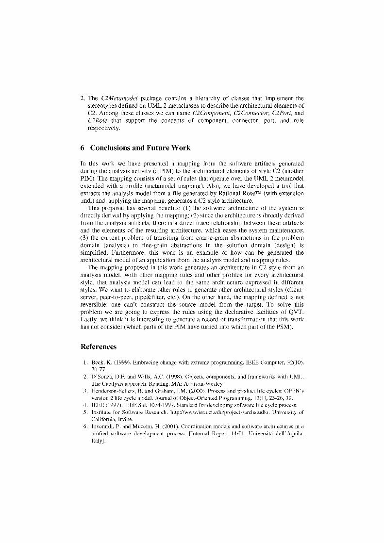
2. The C2Metamodel package contains a hierarchy of classes that implement the stereotypes defined on UML 2 metaclasses to describe the architectural elements of C2. Among these classes we can name C2Component, C2Connector, C2Port, and C2Role that support the concepts of component, connector, port, and role respectively.
6 Conclusions and Future Work
In this work we have presented a mapping from the software artifacts generated during the analysis activity (a PIM) to the architectural elements of style C2 (another PIM). The mapping consists of a set of rules that operate over the UML 2 metamodel extended with a profile (metamodel mapping). Also, we have developed a tool that extracts the analysis model from a file generated by Rational Rose™ (with extension .mdl) and, applying the mapping, generates a C2 style architecture.
This proposal has several benefits: (1) the software architecture of the system is directly derived by applying the mapping; (2) since the architecture is directly derived from the analysis artifacts, there is a direct trace relationship between these artifacts and the elements of the resulting architecture, which eases the system maintenance; (3) the current problem of transiting from coarse-grain abstractions in the problem domain (analysis) to fine-grain abstractions in the solution domain (design) is simplified. Furthermore, this work is an example of how can be generated the architectural model of an application from the analysis model and mapping rules.
The mapping proposed in this work generates an architecture in C2 style from an analysis model. With other mapping rules and other profiles for every architectural style, that analysis model can lead to the same architecture expressed in different styles. We want to elaborate other rules to generate other architectural styles (client-server, peer-to-peer, pipe&filter, etc.). On the other hand, the mapping defined is not reversible: one can't construct the source model from the target. To solve this problem we are going to express the rules using the declarative facilities of QVT. Lastly, we think it is interesting to generate a record of transformation that this work has not consider (which parts of the PIM have turned into which part of the PSM).
References
1. Beck, K. (1999). Embracing change with extreme programming. IEEE Computer, 32(10), 70-77.
2. D'Souza, D.F. and Wills, A.C. (1998). Objects, components, and frameworks with UML. The Catalysis approach. Reading, MA: Addison-Wesley.
3. Henderson-Sellers, B. and Graham, I.M. (2000). Process and product life cycles: OPEN's version 2 life cycle model. Journal of Object-Oriented Programming. 13(1), 23-26, 39.
4. IEEE (1997). IEEE Std. 1074-1997. Standard for developing software life cycle process. 5. Institute for Software Research, http://www.isr.uci.edu/projects/archstudio. University of
California, Irvine. 6. Inverardi, P. and Muccini, H. (2001). Coordination models and software architectures in a
unified software development process. [Internal Report 14/01. Universita dell'Aquila, Italy].

7. Jacobson, I., Booch, G. and Rumbaugh, J. (1999). The unified software development process. MA: Addison-Wesley.
8. Medvidovic, N. (1999). Architecture-based specification-time software evolution. (Doctoral Dissertation, University of California, Irvine, 1999).
9. Mellor, S.J., Scott, K., Uhl, A. and Weise, D. (2004). MDA distilled: principles of model-driven architecture. Boston: Addison-Wesley
10. Object Management Group (2003). MDA guide Vl.0.1. Document number omg/2003-06-01, Date: 12111 June 2003.
11. Object Management Group (2004). Unified Modeling Language (UML) Specification: Infrastructure version 2.0. ptc/04-10-14. Finalized Convenience Document.
12. Object Management Group (2004). Meta Object Facility (MOF) 2.0 Core Specification. ptc/04-10-15. OMG Available Specification.
13. Object Management Group (2005). Unified Modeling Language: Diagram Interchange version 2.0. ptc/05-06-04. Convenience Document.
14. Object Management Group (2005). OCL 2.0 Specification version 2.0. ptc/2005-06-06. 15. Object Management Group (2005). Unified Modeling Language: Superstructure version
2.0. formal/05-07-04. 16. Object Management Group (2005). MOF QVT Final Adopted Specification, ptc/05-11-01. 17. Perez-Martinez, J.E. and Sierra-Alonso, A. (2004). UML 1.4 versus UML 2.0 as
Languages to Describe Software Architectures. First European Workshop on Software Architecture (EWSA 2004). St. Andrews - Scotland (UK).
18. Perez-Martinez, J.E. and Sierra-Alonso, A. (2005). UML 2.0 can't represent architectural connectors. 3rd Nordic Workshop on UML Software Modeling. Tampere, Finland.
19. Shaw, M. and Garlan, D. (1996). Software architecture. Perspectives on an emerging discipline. Prentice-Hall.
20. Sommerville, I. (2004). Software Engineering, 7' ed. Addison-Wesley.