frit facts - techneglas, dopant sources, glass · pdf filefrit facts a brief technological...
TRANSCRIPT
FRIT FACTS
A Brief Technological Summary OfTELEVISION SOLDER GLASS
For CRT Technicians,Engineers And Managers
TECHNEGLAS Spans The Globe
Courtesy of TECHNEGLAS, INC.
Technical ProductsLevis Development Park, Bldg. #52
Perrysburg, OH 43551
Phone 419-247-7032Fax 419-247-7071

2
Frit SeminarContents
1. Composition and Properties
2. Frit Types and Specifications
3. Mixing and Dispensing
4. Drying and Dielectric Strength
5. Frit Lehr Sealing Cycle
6. Seal Geometry and Stresses
7. Thermal Rates and Differentials
8. Exhaust Cycle and Implosions
9. Salvage Process
10. High Strength TV Solder Glass
11. General Discussion
TECHNEGLAS
3
Composition And Properties
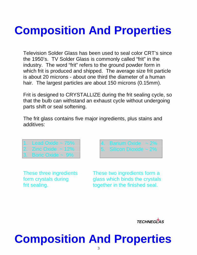
Television Solder Glass has been used to seal color CRT’s sincethe 1950’s. TV Solder Glass is commonly called “frit” in theindustry. The word “frit” refers to the ground powder form inwhich frit is produced and shipped. The average size frit particleis about 20 microns - about one third the diameter of a humanhair. The largest particles are about 150 microns (0.15mm).
Frit is designed to CRYSTALLIZE during the frit sealing cycle, sothat the bulb can withstand an exhaust cycle without undergoingparts shift or seal softening.
The frit glass contains five major ingredients, plus stains andadditives:
These three ingredients These two ingredients form aform crystals during glass which binds the crystalsfrit sealing. together in the finished seal.
TECHNEGLAS
Composition And Properties
4. Barium Oxide ~ 2%5. Silicon Dioxide ~ 2%
1. Lead Oxide ~ 75%2. Zinc Oxide ~ 12%3. Boric Oxide ~ 9%

4
A mixture of two types of crystals develops during the frit seal:
Small, slow-growing2 Lead, 1 Zinc, 1 Boron
Large, fast-growing1 Lead, 2 Zinc, 1 Boron
40microns
15microns
2 PbO-ZnO-B2O3 PbO-2ZnO-B2O3
The final crystallized Solder Glass looks like this:
BaO-SiO 2Glass
Because solder glass is a high lead material, it is considered aHAZARDOUS MATERIAL, and the primary exposure route isthrough inhalation or ingestion. Disposal should be asHAZARDOUS WASTE, EPA Waste ID Number: D008.
TECHNEGLAS

5
Typical Frit Types And SpecsThe three most widely used television frits sold by Techneglasare:
The sealing behavior and general specifications for these frits areidentical.________________________________________________
Frit Properties and General Specifications
Property Test Conditions Typical Specification
Button Flow 440�C, 60 Min. 27.4mm +/- 0.8mm
Rod Seal (Comp.) 440�C, 60 Min. 40 +/- 30 Kg./Sq.Cm.
DTA Peak Time 440�C Isothermal 22 +/- 5 Min.
DTA Completion Time 440�C Isothermal 30 +/- 6 Min.
Glassy Edge Gradient Boat 60 Min. 370�C +/- 6�C
Crystallization Edge Gradient Boat 60 Min. 420�C +/- 6�C
Sieve Analysis Percent - 37 Microns 68 +/- 5%
Dispensing Bead Width Amyl Acetate Vehicle 6.5mm +/- 1.0mm (12.5 to 1 Frit/Vehicle Ratio)
TECHNEGLAS
FRIT TESTING
CV-1608
Black Contains1% Mn203
Colorant
CV-685
Yellow DoesNOT ContainColorants
CV-1610
Gray Contains0.3% Mn203
Colorant

6
GlassFrit
0 10 20 30
Button Flow DTA Iso Time 440�C
GlassStandard 200 300 400 500
Frit
Rod Seal Gradient Boat, �CStress Mismatch
TECHNEGLAS
Manufacturing Process

7
The manufacturing process consists of six steps:
1. Batch Weighing And Mixing
2. Melting And Chip Forming
3. Ball Milling And Initial Screening
4. Blending With Additives And Pre-Test
5. Final Screening
6. Packaging
TECHNEGLAS

8
Mixing And Dispensing
To dispense Solder Glass, it must first be mixed with a two-partvehicle. One part is a solvent (Amyl Acetate or Butyl Acetate)which provides FLUIDITY to the mix. The second part is aBINDER (Nitrocellulose) which holds the frit particles on the sealedge during frit seal, until the particles melt together and flow.Usually 1 to 1.5% of the vehicle is binder. For a given vehiclesystem, the paste viscosity will increase as the nitrocellulosecontent is increased (see chart below):
Paste Viscosity as a function of % NITROCELLULOSE
0.12
0.13
0.14
0.15
0.16
0.17
0.9 1.0 1.1 1.2 1.3 1.4
Viscosity
% Nitrocellulose
NOTE: Paste viscosity is defined as the reciprocal of the beadwidth (1/mm.) as measured in millimeters using theTECHNEGLAS dispensing test.
TECHNEGLAS
9
MIXING
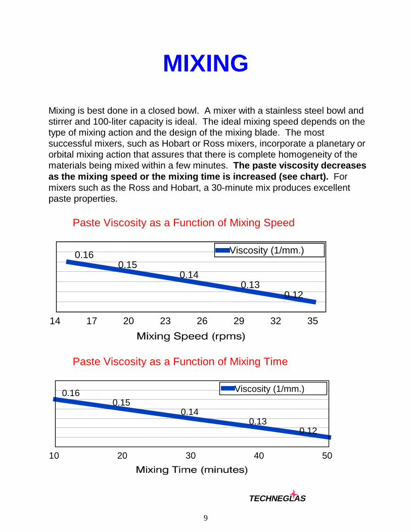
Mixing is best done in a closed bowl. A mixer with a stainless steel bowl andstirrer and 100-liter capacity is ideal. The ideal mixing speed depends on thetype of mixing action and the design of the mixing blade. The mostsuccessful mixers, such as Hobart or Ross mixers, incorporate a planetary ororbital mixing action that assures that there is complete homogeneity of thematerials being mixed within a few minutes. The paste viscosity decreasesas the mixing speed or the mixing time is increased (see chart). Formixers such as the Ross and Hobart, a 30-minute mix produces excellentpaste properties.
Paste Viscosity as a Function of Mixing Speed
0.160.15
0.140.13
0.12
14 17 20 23 26 29 32 35
Viscosity (1/mm.)
Paste Viscosity as a Function of Mixing Time
0.160.15
0.140.13
0.12
10 20 30 40 50
Viscosity (1/mm.)
TECHNEGLAS
10
MIXING
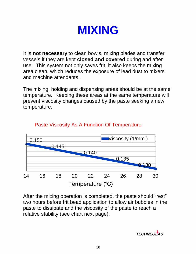
It is not necessary to clean bowls, mixing blades and transfervessels if they are kept closed and covered during and afteruse. This system not only saves frit, it also keeps the mixingarea clean, which reduces the exposure of lead dust to mixersand machine attendants.
The mixing, holding and dispensing areas should be at the sametemperature. Keeping these areas at the same temperature willprevent viscosity changes caused by the paste seeking a newtemperature.
Paste Viscosity As A Function Of Temperature
0.1500.145
0.1400.135
0.130
14 16 18 20 22 24 26 28 30
Viscosity (1/mm.)
After the mixing operation is completed, the paste should “rest”two hours before frit bead application to allow air bubbles in thepaste to dissipate and the viscosity of the paste to reach arelative stability (see chart next page).
TECHNEGLAS

11
Paste Viscosity
As a Function of Time After Mixing
Viscosity (Reciprocal of Bead Width)
0.0 0.5 1.0 1.5 2.0 2.5 3.0 3.5 4.00.12
0.13
0.14
0.15
0.16
0.17Viscosity (1/mm.)
TECHNEGLAS

12
Typical Bead ShapesDispensing is best done by a robot tracking to a theoretical sealedge and a screw feeder to control the amount dispensed at eachpoint on the funnel.
Advantages & Disadvantages
Narrow
Medium
Low
+ Permits higher frit weights+ Easier tracking- Slower drying, can break off- Greater panel / funnel separation - Frit must travel farther along seal edge
+Permits adequate frit weight+ Reasonable tracking controlGood compromise on drying and green strengthPanel / funnel separation is reasonableFrit travel along seal edge is reasonable
+ Fast drying and strong+ Frit travel along seal edge is minimal+ Panel / funnel separation is minimal- Hard to achieve higher frit weights- Tends to run off seal edge
40 - 60%
60 - 80%
80 - 95%
Typical Frit Weights By Bulb Size: (Frit Weight, Wet, In Grams)
13 19 20 26 27 30 32 35
Min. 35 50 55 80 87 105 120 135
Target 40 55 60 90 95 115 130 150
Max. 45 60 65 100 110 125 145 165
TECHNEGLAS
13
Bubbles In FritNormal frit contains some bubbles from .1 or .2 mm in size, andoccasional bubbles up to .5 mm are not unusual or harmful.
Typical frit contains 2% to 7% bubbles as a fraction of viewed cross-section area.
Bubbles can be caused by:
• Space left from solvent evaporation.
• About 40% of mixed paste is vehicle. Some voids left after drying may
remain after melting.
• Bubbles introduced in mixing pot (blades, etc.).(*)
• Bubbles which do not rise - paste too thick. (*)
• Bubbles from dispense head or screw.
• These bubbles will normally appear as a row (or line) of bubbles.
• Bubbles from tearing of catenary (paste too dry).(*)
• These appear as a row or line of small bubbles in the middle of the seal.
• Oxidation of amyl acetate; C0 + C02 = H20
• Oxidation of nitrocellulose; C02 + H20.
• These are normally very small. In CV-685 they appear clean.
• Dust, dirt or fibers on frit bead.(*)
• Dirty seal edges.
• Grooving of frit bead from thin paste(*) →
(*) The usual cause of HARMFUL bubbles.
TECHNEGLAS
14
Drying
The drying of a dispensed bead is dependent on several factors:
á Time- The average bead using 1.25% nitrocellulose in amyl acetate requires 1.5
hours in ambient conditions to dry sufficiently. However, a 30-minuteoven cycle plus ambient is typical.
á Temperature- Keeping the frit bead between 50 and 75�C is a safe temperature range
for drying. If the drying profile is excessive, the nitrocellulose will begin tooxidize, or crusting of the top surface will occur.
á Type of Heating- Can be ambient air, or assisted with heating elements. Having the
funnels heated prior to fritting speeds the process.
á Placement of Heating Source- The heating source should be below the seal edge to avoid overheating,
which can cause crusting of the frit bead.
á Air Circulation- Fumes should be exhausted. Air flow should not be turbulent.
á Geometric Shape of Bead- The flatter the bead, the faster the evaporation rate due to increased
surface area and less thickness.
á Percent Nitrocellulose- The higher the nitrocellulose content, the slower the evaporation rate.
á Type of Solvent- Paste made with butyl acetate vehicle dries significantly faster.
TECHNEGLAS
15
Drying
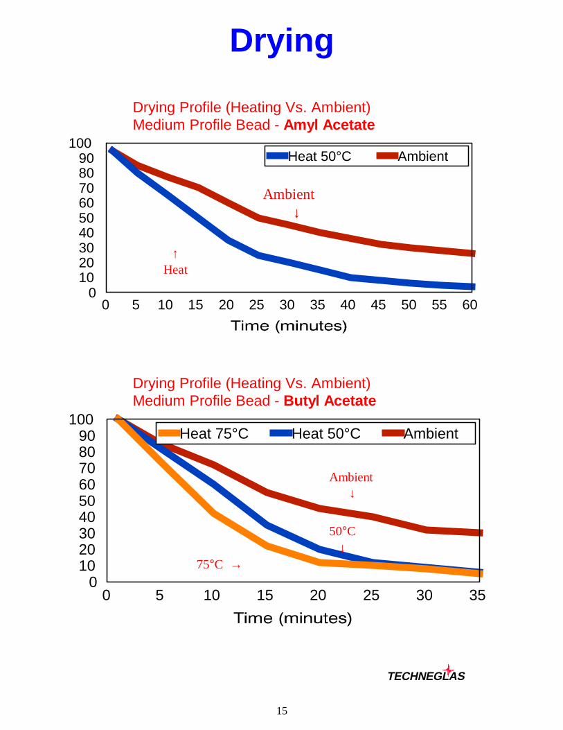
Drying Profile (Heating Vs. Ambient)Medium Profile Bead - Amyl Acetate
0 5 10 15 20 25 30 35 40 45 50 55 600
102030405060708090
100Heat 50°C Ambient
Drying Profile (Heating Vs. Ambient)Medium Profile Bead - Butyl Acetate
0 5 10 15 20 25 30 350
102030405060708090
100Heat 75°C Heat 50°C Ambient
TECHNEGLAS
Ambient ↓
↑ Heat
Ambient ↓
50°C ↓
75°C →
16
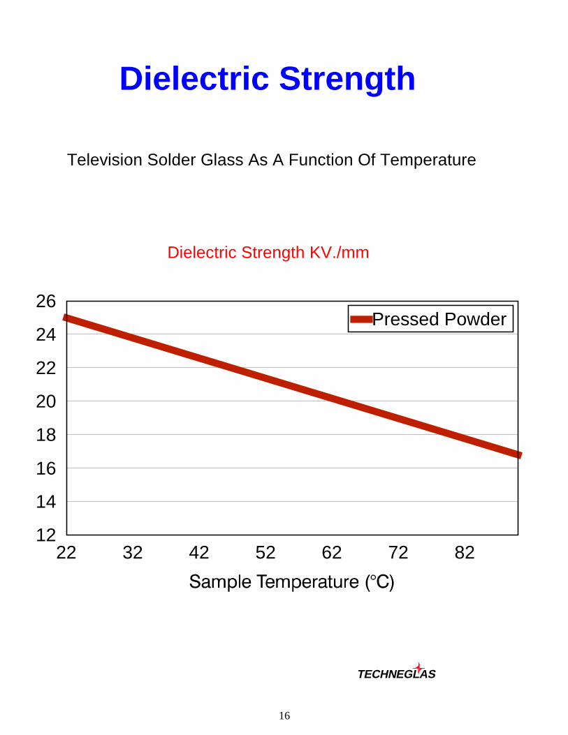
Dielectric Strength
Television Solder Glass As A Function Of Temperature
Dielectric Strength KV./mm
22 32 42 52 62 72 8212
14
16
18
20
22
24
26Pressed Powder
TECHNEGLAS
17
High Voltage BreakdownBulbs with perfectly clean seals can pass 60 to 100 KV. High Voltage breakdownis caused by contamination.
What To Look For:
á Panel Seal Edge Contamination
- Lacquer, matrix, phosphor, poor SE cleaning, conveyor marks,fingerprints.
- Manual loading of panel at the sealing lehr can contaminate the 3 and9 o’clock points.
- Improperly cleaned glass in the corners or contaminated bevels.- The corner and bevels are the most difficult area of the seal edge to
clean due to shape, surface finish irregularities, and position.
á Frit Bead Contamination
- Fibers on the dispensed bead, poor drying, oil in the paste, and“chimney” effect during frit sealing.
á Panel/Funnel Scratches
- Across the seal edge, or diagonally across in the corners.
á Funnel Contamination
- Dag or graphite or iron oxide on seal edge; poor cleaning.
- Even though the dag does not touch the seal edge, theelectrical path length through the seal is shorter, givingrise to higher current leakage.
á Induced Stresses From Banding And Evacuation (Slow Dielectric Failures)
- Mechanical stress concentrations increase chances of failure.
á Studs and Buttons (Electric Field Concentrations)
- The stud and button areas can be points of higher failures.
TECHNEGLAS

18
Frit Lehr Sealing Cycle
The frit lehr cycle has a peak temperature of 446�C plus or minus 4�C. Hold timeshould be 35 to 45 minutes for sizes up to 27-inch, and 40 to 50 minutes for largersizes. The heating rate between 375 and 440�C should be 4 to 6�C per minutefor small and intermediate sizes, and 3 to 5.5�C per minute for large sizes. Thisheating rate is called the “approach” heating rate, and it affects seal thickness,bead geometry, and leading-trailing edge, “delta T”.
0 20 40 60 80 100 120 140 1600
50
100
150
200
250
300
350
400
450
Heating Approach Hold Cooling
1) Heating, usually 6 to 11�C per minute. Evaporation of remaining solvent.2) Burnout of binder, start of glass particle fusion.3) “Approach HR”. Fusion complete; wetting, flow, and fillet formation underway.4) Flow complete, wetting nearly complete. Crystal growth starts.5) Crystal growth rate maximum; crystals nearly full size.6) Crystallization completes on leading and trailing edges. 92 to 96% crystallized.7) Tube annealing.8) Cooling, slow enough not to cause breakage (2.5 to 7�C/Min.).
TECHNEGLAS
1
2
3
4 5 6 7
8

19
Events Occurring During Soak
Hold Time In Frit Seal
Fillets Formed ~ 1 Min. Wetting/Nucleation
*******
Completion
TECHNEGLAS
20
Panel - FunnelSeparation
Direction of Travel
→ → → → → →
1.5 mm.
0.2 mm.
At lehr load
Start of FS "hold"
TECHNEGLAS

21
Thermal Contraction
Panel Vs. Frit
Mismatch, Kg./Sq. Cm.
0 50 100 150 200 250 300 350 400 450 500
050
100150200250300350400450500
-50-100
Frit Panel
TECHNEGLAS
22
Mismatch Vs. Holding Time
Compression in Frit at 440�C
Mismatch, Kg./Sq. Cm.
0
5
10
15
20
25
30
35
4030 45 60
30 Minutes 45 Minutes 60 Minutes
Hold Time at 440�C
TECHNEGLAS

23
Mismatch Vs. Temperature
Compression In Frit
Mismatch, Kg./Sq. Cm.
0
5
10
15
20
25
30
35
40440 445 450
440�C 445�C 450�C
Sealing Temperature
TECHNEGLAS

24
Frit Seal Thermal RatesDegrees C Per Minute
___________________________________________________________14” - 17”
Range 100-375 375-445 Hold 445 Cool RateIdeal 6-9 4.5-6.0 35 Min. < 2.5Good 9-14 6.0-7.0 30 Min. 2.5-4.5Improper > 15 > 7 < 28 Min. > 4.5
___________________________________________________________20”
Range 100-375 375-445 Hold 445 Cool RateIdeal 6-8 4.5-5.5 40 Min. < 2.5Good 8-12 5.5-6.5 35 Min. 2.5-4.0Improper > 12 > 6.5 < 32 Min. > 4.0
___________________________________________________________27”
Range 100-375 375-445 Hold 445 Cool RateIdeal 6-8 4.0-5.5 40 Min. < 2.5Good 8-11 5.5-6.5 35 Min. 2.5-3.5Improper > 11 > 6.5 < 32 Min. > 3.5
___________________________________________________________32”
Range 100-375 375-445 Hold 445 Cool RateIdeal 5-7 3 50 Min. < 2.5Good 7-10 4.5-6.0 40 Min. 2.5-3.5Improper > 10 > 6.0 < 32 Min. > 3.5
___________________________________________________________35”
Range 100-375 375-445 Hold 445 Cool RateIdeal 4.5-6.5 2.8-4.3 55 Min. < 2.5Good 6.5-9.5 4.3-5.5 40 Min. 2.5-3.3Improper > 9.5 > 5.5 < 35 Min. > 3.3
___________________________________________________________
TECHNEGLAS
25
Fillet Shape Analysis
Examination of cross-sections can be very informative. Use a glasssaw to cut at least four sections: leading edge, trailing edge, middleaxis, and a corner. These will show:
1. Parts Match
2. Fillet Shape
3. Amount of Frit
4. Seal Thickness
5. Possible Offset
6. Amount of Seal Land
7. Bevel Shape and Fill
8. Stress, if Polarimeter is Used
TECHNEGLAS

26
Fillet Shape
What to Look For:
C
C C
C
Seal thickness.2mm.
Compression near fillets
Good Seal Too muchfrit
Too much fritdispensed
inside
Thin seal
Fillet drooptemp. too high
Frit weightok
Not enoughfrit disp. ok
Not enoughfrit
TECHNEGLAS
27
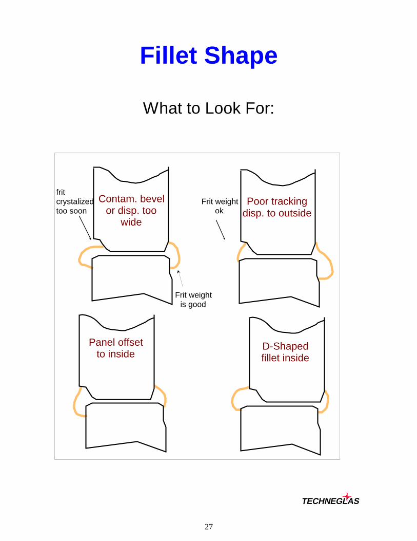
Fillet Shape
What to Look For:
Frit weightok
Poor trackingdisp. to outside
Panel offset to inside
D-Shapedfillet inside
frit crystalizedtoo soon
Contam. bevelor disp. too
wide
Frit weight is good
TECHNEGLAS

28
Fillet Shape
What to Look For:
Thin seal.1 mm.
Thick seal.4 mm.
Contam. lehratmosphere
Tilt
TECHNEGLAS

29
Exhaust CycleThe exhaust cycle usually has a peak temperature of 300 to 325�C. Hold time isusually brief (0 to 5 minutes). The heating rate should be kept low to avoidUPSHOCK implosions from INSIDE sources. Typical heating rates are 5 to9�C/min. for small and intermediate sizes and 3.5 to 5.5�C/min. for large sizes. Ifa major problem of “Cracked Bulbs” exists, the heating rate over the first 250�Cmust be slowed down. The COOLING RATE should be 2.5 to 4�C/min. for smalland intermediate sizes and 2 to 3�C/min. for larger sizes to avoid OUTSIDESOURCE losses.
0 20 40 60 80 100 120 140 1600
50
100
150
200
250
300
350
Heating Approach Cooling
Typical Inside Source Implosions:Studs Inside Contamination (Inside TensionOffsets Scratched Necks During Heating)Inside Frit Re-Entrants Scratched Lug Area
________________________________________Typical Outside Source Implosions:Bump Checks Frit Drips/Overlap Drips (Outside TensionFrit Seal Near Pads Button (Anode) Area During Cooling)Outside Panel Bevel Checked Pads Contamination
TECHNEGLAS

30
ExhaustWhen a new line or bulb size is started or when the speed is increased onan older exhaust line, a significant imbalance may occur in the chroniclosses between heating losses (upshock) and cooling losses (downshock).If heating losses are predominant, an effort should be made to move thepeak exhaust temperature ahead a few zones to lower the heating rate andthereby reduce upshock breakage. If cooling losses are predominant, thepeak exhaust temperature should be moved back a few zones to lower thecooling rate and thereby reduce downshock breakage.
Minimum TOTAL implosions will occur if upshock and downshocklosses are about equal.
Exhaust Curve - Heating Losses Predominant
0 2 4 6 8 10 12 14 16 18 20 22 24 26 28 300
50
100
150
200
250
300
350
Curve A - Peak Zone 9 Curve B - Peak Zone 10 Curve C - Peak Zone 11
Heating Losses - 32 Heating Losses - 16 Heating Losses - 8Cooling Losses - 4 Cooling Losses - 6 Cooling Losses - 8TOTAL Losses - 36 TOTAL Losses - 22 TOTAL Losses - 16
TECHNEGLAS

31
Exhaust Thermal Rates Degrees C Per Minute
___________________________________________________________14” - 17”
Range 100-270 270-Ex.T Hold Cool RateIdeal 5-8 4.5-6.0 5 Min. < 3Good 8-11 6.0-7.0 3.0-4.0Improper > 11 > 7 > 4.0
___________________________________________________________20”
Range 100-270 270-Ex.T Hold Cool Rate Ideal 5-8 4.5-5.5 5 Min. < 2.5Good 8-10 5.5-6.5 2.5-3.4Improper > 10.5 > 7 > 3.5
___________________________________________________________27”
Range 100-270 270-Ex.T Hold Cool RateIdeal 5-7 4.5-5.5 5 Min. < 2.5Good 7-9 5.5-6.5 2.5-3.4Improper > 9.5 > 7 > 3.5
___________________________________________________________32”
Range 100-270 270-Ex.T Hold Cool RateIdeal 5-6.5 4.5-5.5 5 Min. < 2.5Good 6.5-9 5.5-6.5 2.5-2.9Improper > 9.5 > 6.5 > 3.0
___________________________________________________________35”
Range 100-270 270-Ex.T Hold Cool RateIdeal 4.5-6 4-5 5 Min. < 2Good 6-9 5-6.5 2-2.6Improper > 9 > 6.5 > 2.7
___________________________________________________________
TECHNEGLAS

32
Salvage Process
TTTT
TT
T
T
00
00
CC
CC
CC
CC
0
0
T
T
T
TT
T
(Hot Nitric Acid)Debead, temp. 48 to 55°C
(Hot water or acid)High temp. stabilization of
bulb~55°C
Step 1 Step 2
Step 3 Step 4
(Cold Water)Cold shock forms first crack
(Tension on OUTSIDE of
(Hot Water)Hot shock finishes crack
(Tension on INSIDE of bulb)
Salvage Losses: Causes:
Gross Breaks Excessive Thermal ShockPoor Contraction Match of PartsPoor Water Distribution
Corner Breaks Poor Contraction Match of PartsPoor Water DistributionToo Much Frit Inside Corners
Corner Pulls Insufficient Cold Shock Time(Four Fracture Planes) Poor Water Distribution
Too Much Frit Inside Corners
TECHNEGLAS

33
Salvage
Debead Etch
The optimum etch in a salvage operation removes all of theexternal frit bead and up to 2 mm. of the frit between panel andfunnel. The etch can be deeper at the corners.
Etch Uniformity
The etch must be uniform in depth. “Scalloping” is a veryundesirable condition which should promptly be corrected throughnozzle design or transducer arrangement, or by an oscillatorymovement of the bulb during etch.
Uniform etch Scalloping
TECHNEGLAS

34
Salvage
Gross BreakageExcessive Thermal ShockPoor Concentration Match of PartsPoor Water Distribution
Corner BreaksPoor Contraction Match of PartsPoor Water DistributionToo Much Frit Inside Corners
Corner Pulls(Four Fracture Planes)Insufficient Cold Shock TimePoor Water DistributionToo Much Frit Inside Corners
TECHNEGLAS

35
Thermal Contraction
450 to 25�C
This is a DESIRABLE stress condition. Bulb stress worksFAVORING effective salvage. Panel contraction midwaybetween frit and funnel.
110
F
108
P
106
Frit
GOOD
This is an UNDESIRABLE stress condition. Bulb stress worksAGAINST effective salvage. Panel too high and funnel too low.
106
Frit
BAD
109
107
P F
TECHNEGLAS

36
Salvage
Stresses Developed After Frit SealBending Stress
TT
Stresses Developed in Cold ShockBending Stress & Thermal Stress
TT
TT T
T
TECHNEGLAS
37
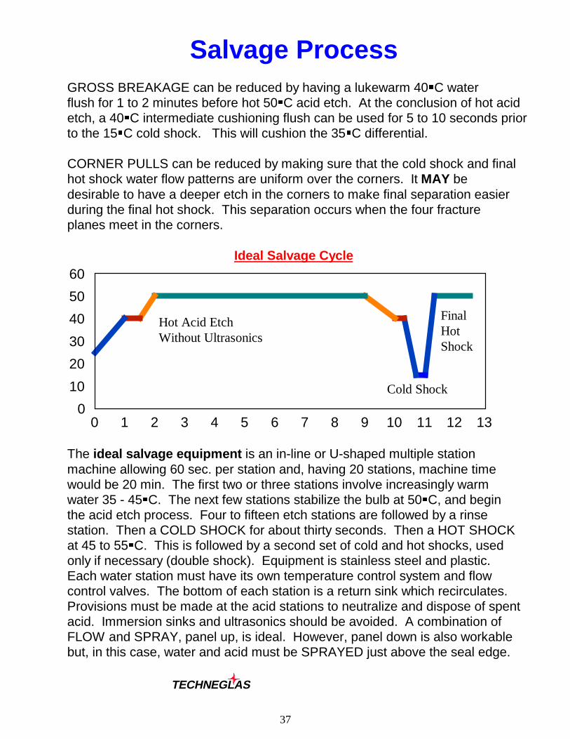
Salvage ProcessGROSS BREAKAGE can be reduced by having a lukewarm 40�C waterflush for 1 to 2 minutes before hot 50�C acid etch. At the conclusion of hot acidetch, a 40�C intermediate cushioning flush can be used for 5 to 10 seconds priorto the 15�C cold shock. This will cushion the 35�C differential.
CORNER PULLS can be reduced by making sure that the cold shock and finalhot shock water flow patterns are uniform over the corners. It MAY bedesirable to have a deeper etch in the corners to make final separation easierduring the final hot shock. This separation occurs when the four fractureplanes meet in the corners.
Ideal Salvage Cycle
0 1 2 3 4 5 6 7 8 9 10 11 12 130
10
20
30
40
50
60
The ideal salvage equipment is an in-line or U-shaped multiple stationmachine allowing 60 sec. per station and, having 20 stations, machine timewould be 20 min. The first two or three stations involve increasingly warmwater 35 - 45�C. The next few stations stabilize the bulb at 50�C, and beginthe acid etch process. Four to fifteen etch stations are followed by a rinsestation. Then a COLD SHOCK for about thirty seconds. Then a HOT SHOCKat 45 to 55�C. This is followed by a second set of cold and hot shocks, usedonly if necessary (double shock). Equipment is stainless steel and plastic.Each water station must have its own temperature control system and flowcontrol valves. The bottom of each station is a return sink which recirculates.Provisions must be made at the acid stations to neutralize and dispose of spentacid. Immersion sinks and ultrasonics should be avoided. A combination ofFLOW and SPRAY, panel up, is ideal. However, panel down is also workablebut, in this case, water and acid must be SPRAYED just above the seal edge.
TECHNEGLAS
Hot Acid EtchWithout Ultrasonics
Cold Shock
FinalHotShock

38
High Strength FritRequirements For High Strength
Chemical Bonding
A strong chemical bond is developed when thebeginning of crystallization is DELAYEDuntil a strong chemical reaction takes placebetween the frit and the panel and funnelglasses. PREMATURE crystallizationinhibits the wetting reaction.TECHNEGLAS high strength frits have apatented nucleation method whichprovides the necessary delayedcrystallization.
Intrinsic Strength
High strength frit must be internally strong.TECHNEGLAS high strength frits gain theirstrength from having a mixture of LARGEand SMALL crystals, bonded together withan optimal glassy matrix. The two crystalsizes are developed by using patentednucleating agents.
Proper Contraction
High strength frit must have proper thermalcontraction to enable development of zones ofCOMPRESSION in the panel and funnelglasses. The compression prevents crackinitiation. TECHNEGLAS high strength fritshave optimum stress characteristics withoutuse of high levels of filler materials. Atypical maximum filler content is 1.5percent, with 1 percent being typical.
C
C
P
F

39
Bulb Pressure Test
Strength Comparison
Normal High Strength0
20
40
60
80
100Pressure test
Pressure test 68 82
TECHNEGLAS

40