frequently asked questions - nerc.com 200717 protection... · prc-005-2 —nerc protection system...
TRANSCRIPT
PPRRCC--000055--22 ——NERC Protection System Maintenance Standard PRC-005-2
FFrreeqquueennttllyy AAsskkeedd QQuueessttiioonnss FREQUENTLY ASKED QUESTIONS -
Practical Compliance and Implementation ((DDrraafftt 11))
April 16, 2010
Informative Annex to Standard PRC-005-2
Prepared by the Protection System Maintenance and Testing Standard Drafting Team
July, 2009
PRC-005-2 — Protection System Maintenance - Frequently Asked QuestionsTable of Contents
Draft 1: July 21, 20092: April, 2010 Page i
Table of Contents
Introduction .......................................................................................................................................................... 2
Executive Summary.............................................................................................................................................. 2
Terms Used in PRC-005-2 .................................................................................................................................... 2
Frequently Asked Questions ................................................................................................................................ 3
I General FAQs: .......................................................................................................................................... 3 II Group by Type of Protection System Component: ....................................................................................... 5 1. All Protection System Components ............................................................................................................. 5 2. Protective Relays ....................................................................................................................................... 5 3. Voltage and Current Sensing Device Inputs to Protective Relays ................................................................ 8 4. Protection System Control Circuitry ......................................................................................................... 10 5. Station dc Supply ..................................................................................................................................... 12 6. Protection System Communications Equipment ........................................................................................ 16 7. UVLS and UFLS Relays that Comprise a Protection System Distributed Over the Power System ............... 18 8. SPS or Relay Sensing for Centralized UFLS or UVLS ............................................................................... 19 III Group by Type of BES Facility: ................................................................................................................ 20 1. All BES Facilities ..................................................................................................................................... 20 2. Generation .............................................................................................................................................. 20 3. Transmission ........................................................................................................................................... 21 IV Group by Type of Maintenance Program:................................................................................................. 22 1. All Protection System Maintenance Programs .......................................................................................... 22 2. Time-Based Protection System Maintenance (TBM) Programs ................................................................. 23 3. Performance-Based Protection System Maintenance (PBM) Programs ..................................................... 25 V Group by Monitoring Level: ..................................................................................................................... 29 1. All Monitoring Levels .............................................................................................................................. 29 2. Level 1 Monitored Protection Systems (Unmonitored Protection Systems) ................................................ 41 3. Level 2 Monitored Protection Systems (Partially Monitored Protection Systems) ...................................... 41 4. Level 3 Monitored Protection Systems (Fully Monitored Protection Systems) ............................................ 42
Appendix A — Protection System Maintenance Standard Drafting Team ....................................................... 43
Index ................................................................................................................................................................... 44
PRC-005-2 — Protection System Maintenance - Frequently-Asked Questions
Draft 1: July 21, 20092: April, 2010 Page 2
Introduction The following is a draft collection of questions and answers that the PSMT SDT believes could be helpful to those implementing NERC Standard PRC-005-2 Protection System Maintenance. As the draft standard proceeds through development, this FAQ document will be revised, including responses to key or frequent comments from the posting process. The FAQ will be organized at a later time during the development of the draft Standard.
This FAQ document will support both the Standard and the associated Technical Reference document.
Executive Summary • To be addedWrite later if needed.
Terms Used in PRC-005-2 Maintenance Correctable Issue – As indicated in footnote 2 of the draft standard, a maintenance correctable issue is a failure of a device to operate within design parameters that can not be restored to functional order by repair or calibration, repair or replacement while performing the initial on-site maintenance activity, and that requires follow-up corrective action.
Segment – As indicated in PRC-005-2 Attachment A Criteria for a Performance-Based Protection System Maintenance Program, a segment is a “A grouping of Protection Systems or component devicescomponents of a particular model or type from a single manufacturer, with other common factors such that consistent performance is expected across the entire population of the segment, and shall only be defined for a population of 60 or more individual components.”
Component – This equipment is first mentioned in Requirement 1, Part 1.1 of this standard. A component is any individual discrete piece of equipment included in a Protection System, such as a protective relay or current sensing device. Types of components are listed in Table 1 (“Maximum Allowable Testing Intervals and Maintenance Activities for Unmonitored Protection Systems”). For components such as dc circuits, the designation of what constitutes a dc control circuit elementcomponent is somewhat arbitrary and is very dependent upon how an entity performs and tracks the testing of the dc circuitry. Some entities test their dc circuits on a breaker basis whereas others test their circuitry on a local zone of protection basis. Thus, entities are allowed the latitude to designate their own definitions of “dc control circuit elementscomponents.” Another example of where the entity has some discretion on determining what constitutes a single component is the voltage and current sensing devices,, where the entity may choose either to designate a full three-phase set of such devices or a single device as a single component.
Countable Event – As indicated in footnote 4 of PRC-005-2 Attachment A, Criteria for a Performance-based Protection System Maintenance Program, countable events include any failure of a component requiring repair or replacement, any condition discovered during the verification activities in Table 1a through Table 1c which requires corrective action, or a Misoperation attributed to hardware failure or calibration failure. Misoperations due to product design errors, software errors, relay settings different from specified settings, Protection System component configuration errors, or Protection System application errors are not included in Countable Events.
PRC-005-2 — Protection System Maintenance - Frequently-Asked Questions
Draft 1: July 21, 20092: April, 2010 Page 3
Frequently Asked Questions
I General FAQs: 1. The standard seems very complicated, and is difficult to understand. Can it be simplified?
Because the standard is establishing parameters for condition-based Maintenance (R2) and performance-based Maintenance (R3) in addition to simple time-based Maintenance, it does appear to be complicated. At its simplest, an entity needs to follow R1 and R4 and perform ONLY time-based maintenance according to Table 1a,, eliminating R2 and R3 from consideration altogether. If an entity then wishes to take advantage of monitoring on its Protection System components, R2 comes into play, along with Tables 1b and 1c. If an entity wishes to use historical performance of its Protection System components to perform performance-based Maintenance, R3 applies.
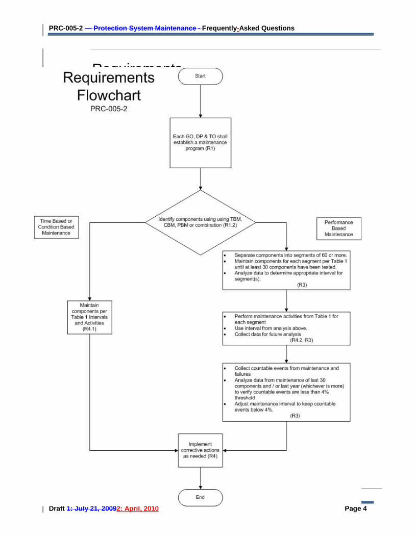
Please see the following diagram, which provides a “flow chart” of the standard.
PRC-005-2 — Protection System Maintenance - Frequently-Asked Questions
Draft 1: July 21, 20092: April, 2010 Page 4
Start
Each GO, DP, & TO shall establish a
maintenance program [R1]
Decide if using Time Based, Condition Baesd, and/or Performance Based
program
Maintain components per Table One Intervals and
Activities [R4.4.1]
Perform maintenance activities from Table One
for each segment with interval from analysis
above and collect data for future analysis [R3, R4.4.2]
Note: GO, DP, & TO may use one or
multiple programs
Performance BasedTime Based
RequirementsFlowchart
PRC-005-2
Implement corrective actions as
needed [R4]
End
• Separate components into appropriate families of 60 or more
• Maintain components for each segment per Table One until at least 30 components have been tested
• Analyze data to determine appropriate interval for segment(s)
[R3]
• Collect countable events from maintenance and failures
• Analyze data from maintenance of last 30 components and/or last year to verify countable events below 4%
• Adjust maintenance interval to keep countable events below 4%
[R3]
Ensure components
have necessary monitoring [R2]
Maintain components per
Table One Intervals and
Activities [R4.4.1]
Condition Based
PRC-005-2 — Protection System Maintenance - Frequently-Asked Questions
Draft 1: July 21, 20092: April, 2010 Page 5
II Group by Type of Protection System Component:
1. All Protection System Components
A. Are power circuit reclosers, reclosing relays,, closing circuits and auto-restoration schemes covered in this standard?
No. As stated in R1, this standard covers protective relays that use measurements of voltage, current and/or phase angle to determine anomalies and to trip a portion of the BES. Reclosers, reclosing relays,, closing circuits and auto-restoration schemes are used to cause devices to close as opposed to electrical-measurement relays and their associated circuits that cause circuit interruption from the BES; such closing devices and schemes are more appropriately covered under other NERC Standards. There is one notable exception: if a Special Protection System incorporates automatic closing of breakers, the related closing devices are part of the SPS and must be tested accordingly.
B. Why does PRC-005-2 not specifically require maintenance and testing procedures as reflected in the previous standard, PRC-005-1?
PRC-005-1 does not require detailed maintenance and testing procedures, but instead requires summaries of such procedures, and is not clear on what is actually required. PRC-005-2 requires a documented Maintenance program, and is focused on establishing Requirements rather than prescribing methodology to meet those Requirements. Between the activities identified in Tables 1a, 1b, and 1c, and the various components of the definition established for a “Protection System Maintenance Program”, PRC-005-2 establishes the activities and time-basis for a Protection System Maintenance Program to a level of detail not previously required.
2. Protective Relays
A. How do I approach testing when I have to upgrade firmware of a microprocessor relay?
The component “Upkeep” in the definition of a Protection System Maintenance Program, addresses “Routine activities necessary to assure that the component remains in good working order and implementation of any manufacturer’s hardware and software service advisories which are relevant to the application of the device.” The Maintenance Activities specified in Table 1a,, Table 1b,, and Table 1c do not present any requirements related to Upkeep for Protective Relays. However, the entity should assure that the relay continues to function properly after implementation of firmware changes.
B. Please clarify what is meant by restoration in the definition of maintenance.
The component “Restoration” in the definition of a Protection System Maintenance Program, addresses corrective activities necessary to assure that the component is returned to working order following the discovery of its failure or malfunction. The Maintenance Activities specified in Table 1a, Table 1b, and Table 1c do not present any requirements related to
PRC-005-2 — Protection System Maintenance - Frequently-Asked Questions
Draft 1: July 21, 20092: April, 2010 Page 6
Restoration; R4.3 of the standard does require that the entity “initiate any necessary activities to correct unresolved maintenance correctable issues”. Some examples of restoration (or correction of maintenance-correctable issues) include, but are not limited to, replacement of capacitors in distance relays to bring them to working order; replacement of relays, or other Protection System components, to bring the Protection System to working order; upgrade of electro-mechanical or solid-state protective relays to micro-processor based relays following the discovery of failed components. Restoration, as used in this context is not to be confused with Restoration rules as used in system operations. Maintenance activity necessarily includes both the detection of problems and the repairs needed to eliminate those problems. This standard does not identify all of the Protection System problems that must be detected and eliminated, rather it is the intent of this standard that an entity determines the necessary working order for their various devices and keeps them in working order. If an equipment item is repaired or replaced then the entity can restart the maintenance-time-interval-clock if desired, however the replacement of equipment does not remove any documentation requirements that would have been required to verify compliance with time-interval requirements; in other words do not discard maintenance data that goes to verify your work
C. If I upgrade my old relays then do I have to maintain my previous equipment maintenance documentation?
If an equipment item is repaired or replaced then the entity can restart the maintenance-activity-time-interval-clock if desired, however the replacement of equipment does not remove any documentation requirements. The requirements in the standard are intended to ensure that an entity has a maintenance plan and that the entity adheres to minimum activities and maximum time intervals. The documentation requirements are intended to help an entity demonstrate compliance. For example, saving the dates and records of the last two maintenance cycles is intended to demonstrate compliance with the interval. Therefore, if you upgrade or replace equipment then you still must maintain the documentation for the previous equipment, thus demonstrating compliance with the time interval requirement prior to the replacement action.
D. What is meant by “Verify that settings are as specified” maintenance activity in tables 1a and 1b?
Verification of settings is an activity directed mostly towards microprocessor based relays.
For relay maintenance departments that choose to test microprocessor based relays in the same manner as electro-mechanical relays are tested, the testing process sometimes requires that some specific functions be disabled. Later tests might enable the functions previously disabled but perhaps still other functions or logic statements were then masked out. It is imperative that, when the relay is placed into service, the settings in the relay be the settings that were intended to be in that relay or as the Standard states “…settings are as specified.”
Many of the microprocessor based relays available today have software tools which provide this functionality and generate reports for this purpose.
For evidence or documentation of this requirement a simple recorded acknowledgement that this was done is sufficient.
The drafting team was careful not to require “…that the relay settings be correct…” because it was believed that this might then place a burden of proof that the specified settings would result in the correct intended operation of the interrupting device. While that is a noble intention, the measurable proof of such a requirement is immense. The intent is simply to check that the settings in the relay match the settings specified to those placed into the relay.
PRC-005-2 — Protection System Maintenance - Frequently-Asked Questions
Draft 1: July 21, 20092: April, 2010 Page 7
E. Are electromechanical relays included in the “Verify that settings are as specified” maintenance activity in tables 1a and 1b?
Verification of settings is an activity directed towards the application of protection related functions of microprocessor based relays. Electromechanical relays require calibration verification by voltage and/or current injection, and thus the settings are verified during calibration activity. In the example of a time-overcurrent relay, a minor deviation in time dial, versus the settings, may be acceptable as long as the relay calibration is within accepted tolerances at the injected current amplitudes. A major deviation may require further investigation, as it could indicate a problem with the relay or an incorrect relay style for the application.
B.F. I use my protective relays only as sources of metered quantities and breaker status for SCADA and EMS through a substation distributed RTU or data concentrator to the control center. What are the maintenance requirements for the relays?
This standard addresses only devices “that are applied on, or are designed to provide protection for the BES.” Protective relays, providing only the functions mentioned in the question, are not included.
C.G. I use my protective relays for fault and disturbance recording, collecting oscillographic records and event records via communications for fault analysis to meet NERC and DME requirements. What are the maintenance requirements for the relays?
For relays used only as disturbance monitoring equipment, the NERC standard PRC-018-1 R3 & R6 states the maintenance requirements, and is being addressed by a Standards activity that is revising PRC-002-1 and PRC-018-1. For protective relays “that are applied on, or are designed to provide protection for the BES,” this standard applies, even if they also perform DME functions.
H. We have a number of installations where we have changed our Protection System components. Some of the changes were upgrades, but others were simply system rating changes that merely required taking relays “out-of-service”. What are our responsibilities when it comes to “out-of-service” devices?
Assuming that your system uprates, upgrades and overall changes meet any and all other requirements and standards then the requirements of PRC-005-2 are simple – if the Protection system component performs a Protection system function then it must be maintained. If the component no longer performs Protection System functions than it does not require maintenance activities under the Tables of PRC-005-2. While many entities might physically remove a component that is no longer needed there is no requirement in PRC-005-2 to remove such component(s). Obviously, prudence would dictate that an “out-of-service” device is truly made inactive. There are no record requirements listed in PRC-005-2 for Protection System components not used.
I. While performing relay testing of a protective device on our Bulk Electric System it was discovered that the protective device being tested was either broken or out of calibration. Does this satisfy the relay testing requirement even though the protective device tested bad, and may be unable to be placed back into service?
Yes, PRC-005-2 requires entities to perform relay testing on protective devices on a given maintenance cycle interval. By performing this testing, the entity has satisfied PRC-005-2
PRC-005-2 — Protection System Maintenance - Frequently-Asked Questions
Draft 1: July 21, 20092: April, 2010 Page 8
requirement although the protective device may be unable to be returned to service under normal calibration adjustments. R4.3 states (the entity must): The entity must assure either that the components are within acceptable parameters at the conclusion of the maintenance activities or initiate any necessary activities to correct unresolved maintenance correctable issues.
J. If I show the protective device out of service while it is being repaired then can I add it back as a new protective device when it returns? If not, my relay testing history would show that I was out of compliance for the last maintenance cycle.
The maintenance and testing requirements (R4.3) (in essence) state that the entity assure the components are within the owner’s acceptable operating parameters, if not then actions must be initiated to correct the deviance. The type of corrective activity is not stated; however it could include repairs or replacements. Documentation is always a necessity (“If it is not documented then it wasn’t done!”) Your documentation requirements will increase, of course, to demonstrate that your device tested bad and had corrective actions initiated. Your regional entity could very well ask for documentation showing status of your corrective actions.
K. What calibration tolerance should be applied on electromechanical relays?
Each entity establishes their own acceptable tolerances when applying protective relaying on their system. For some Protection System components, adjustment is required to bring measurement accuracy within the parameters established by the asset owner based on the specific application of the component. A calibration failure is the result if testing finds the specified parameters to be out of tolerance.
3. Voltage and Current Sensing Device Inputs to Protective Relays
A. What is meant by “…verify the current and voltage circuit inputs from the voltage and current sensing devices to the protective relays …” …” Do we need to perform ratio, polarity and saturation tests every few years?
No. You must proveverify that the protective relay is receiving the expected values from the voltage and current sensing devices (typically voltage and current transformers). This can be as difficult as is proposed by the question (with additional testing on the cabling and substation wiring to ensure that the values arrive at the relays); or simplicity can be achieved by other verification methods. Some examples follow:While some examples follow, these are not intended to represent an all-inclusive list; technology advances and ingenuity should not be excluded from making comparisons and verifications:
• Compare the secondary values, at the relay, to a metering circuit, fed by different current
transformers, monitoring the same line as the questioned relay circuit.
• Compare the individual phase secondary values at the relay panel (with additional testing on the panel wiring to ensure that the values arrive at those relays) with the other phases, and verify that residual currents are within expected bounds
PRC-005-2 — Protection System Maintenance - Frequently-Asked Questions
Draft 1: July 21, 20092: April, 2010 Page 9
• Observe all three phase currents and the residual current at the relay panel with an oscilloscope, observing comparable magnitudes and proper phase relationship, with additional testing on the panel wiring to ensure that the values arrive at the relays.
• Compare the values, as determined by the questioned relay, (such as, but not limited to, a query
to the microprocessor relay), to another protective relay monitoring the same line, with currents supplied by different CTs.CT’s.
• Compare the secondary values, at the relay with values measured by test instruments (such as,
but not limited to multi-meters, voltmeter, clamp-on ammeters, etc) and verified by calculations and known ratios to be the values expected. For example a single PT on a 100KV bus will have a specific secondary value that when multiplied by the PT ratio arrives at the expected bus value of 100KV.
• Query SCADA for the power flows at the far end of the line protected by the questioned relay,
compare those SCADA values to the values as determined by the questioned relay.
• Totalize the Watts and VARs on the bus and compare the totals to the values as seen by the questioned relay. The point of the verification procedure is to ensure that all of the individual components are functioning properly; and that, an ongoing proactive procedure is in place to re-check the various components of the protective relay measuring systems.
B. The verification of phase current and voltage measurements by comparison to other quantities seems reasonable. How, though, can I verify residual or neutral currents, or 3V0 voltages, by comparison, when my system is closely balanced?
These values will be zero, or very small, for any reasonably balanced system. To verify these values by comparison, you will need to rely on the normal condition that your system is not perfectly balanced, and there will usually be a small zero-sequence current or voltage, and these values can be measured with instruments having a sufficiently low resolution range. A reading of precisely zero will probably suggest that there is an opening (or some other problem) in the measuring circuit. A finite value of a few percent of the phase quantities, however, may suggest that the measuring circuit is indeed performing properly.
Since these inputs are verified at commissioning, maintenance verification requires ensuring that phase quantities are as expected and that 3IO and 3VO quantities appear equal to or close to 0.
These quantities may be also verified by use of oscillographic records for connected microprocessor relays as recorded during system disturbances. Such records may compare to similar values recorded at other locations by other microprocessor relays for the same event, or compared to expected values (from short circuit studies) for known fault locations.
C. Is wiring insulation or hi-pot testing required by this Maintenance Standard?
No, wiring insulation and equipment hi-pot testing are not required by the Maintenance Standardspecifically required by the Maintenance Standard. However, if the method of verifying CT and PT inputs to the relay involves some other method than actual observation of
PRC-005-2 — Protection System Maintenance - Frequently-Asked Questions
Draft 1: July 21, 20092: April, 2010 Page 10
current and voltage transformer secondary inputs to the relay, it might be necessary to perform some sort of cable integrity test to verify that the instrument transformer secondary signals are actually making it to the relay and not being shunted off to ground. For instance, you could use CT excitation tests and PT turns ratio tests and compare to baseline values to verify that the instrument transformer outputs are acceptable. However, to conclude that these acceptable transformer instrument output signals are actually making it to the relay inputs, it also would be necessary to verify the insulation of the wiring between the instrument transformer and the relay.
D. My plant generator and transformer relays are electromechanical and do not have metering functions as do microprocessor based relays. In order for me to compare the instrument transformer inputs to these relays to the secondary values of other metered instrument transformers monitoring the same primary voltage and current signals, it would be necessary to temporarily connect test equipment like voltmeters and clamp on ammeters to measure the input signals to the relays. This practice seems very risky and a plant trip could result if the technician were to make an error while measuring these current and voltage signals. How can I avoid this risk? Also, what if no other instrument transformers are available which monitor the same primary voltage or current signal?
Comparing the input signals to the relays to the outputs of other independent instrument transformers monitoring the same primary current or voltage is just one method of verifying the instrument transformer inputs to the relays but is not required by the standard. Plants can choose how to best manage their risk. If online testing is deemed too risky, offline tests such as, but not limited to, CT excitation test and PT turns ratio tests can be compared to baseline data and be used in conjunction with CT and PT secondary wiring insulation verification tests to adequately “verify the current and voltage circuit inputs from the voltage and current sensing devices to the protective relays …” while eliminating the risk of tripping an in service generator or transformer. Similarly, this same offline test methodology can be used to verify the relay input voltage and current signals to relays when there are no other instrument transformers monitoring available for purposes of signal comparison.
4. Protection System Control Circuitry
A. Is it permissible to verify circuit breaker tripping at a different time (and interval) than when we verify the protective relays and the instrument transformers?
Yes, provided the entire Protective System is tested within the individual components’ maximum allowable testing intervals.
B. The Protection System Maintenance Standard describes requirements for verifying the tripping of circuit breakers. What is this telling me about maintenance of circuit breakers?
Requirements in PRC-005-2 are intended to verify the integrity of tripping circuits,, including the breaker trip coil,, as well as the presence of auxiliary supply (usually a dc battery)) for energizing the trip coil if a protection function operates. Beyond this, PRC-005-2 sets no requirements for verifying circuit breaker performance, or for maintenance of the circuit breaker.

PRC-005-2 — Protection System Maintenance - Frequently-Asked Questions
Draft 1: July 21, 20092: April, 2010 Page 11
C. How do I test each dc Control Circuit path, as established for level 2 (partially monitored protection systems) monitoring of a “Protection System Control Circuitry (Trip coils and auxiliary relays)”?
Table 1b specifies that each breaker trip coil,, auxiliary relay,, and lockout relay must be operated within the specified time period. The required operations may be via targeted maintenance activities, or by documented operation of these devices for other purposes such as fault clearing.
D. What does this standard require for testing an Auxiliary Tripping Relay?
Table 1 requires that the trip test must verify that the auxiliary tripping relay (94) (s) and/or lockout relay (86) operates(s) operate(s) electrically and that their trip output(s) perform as expected. Auxiliary outputs not in a trip path (i.e. alarming or DME input) are not required to be checked.
E. What does a functional trip test include?
An operational trip test must be performed on each portion of a trip circuit. Each control circuit path that produces a trip signal must be verified; this includes trip coils, auxiliary tripping relays (94),, lockout relays (86), and communications--assisted-trip schemes.
A trip test may be an overall test that verifies the operation of the entire trip scheme at once, or it may be several tests of the various portions that make up the entire trip schemepath, provided that testing of the various portions of the trip scheme verifies all of the portions, including parallel paths, and overlaps those portions.
A circuit breaker or other interrupting device needs to be trip tested at least once per trip coil. Breaker auxiliary contacts that are essential for the proper operation of the protective relay trip-circuit (or trip-logic) must be verified as providing the correct breaker open/close status information to the Protection System...
Discrete-component auxiliary relays (94) and lock-out relays (86) must be provenverified by trip test.. The trip test must verify that the auxiliary or lock-out relay operates electrically and that the relay’s trip output(s) change(s) state. Software latches or control algorithms, including trip logic processing implemented as programming component such as a microprocessor relay that take the place of (conventional) discrete component auxiliary relays or lock-out relays do not have to be routinely trip tested.
Normally-closed auxiliary contacts from other devices (for example, switchyard-voltage-level disconnect switches, interlock switches, or pressure switches) which are in the breaker trip path do not need to be tested.
F. Is a Sudden Pressure Relay an Auxiliary Tripping Relay?
No. IEEE C37.2-2008 assigns the device number 94 to auxiliary tripping relays. Sudden pressure relays are assigned device number 63, and is excluded from the Standard by footnote 1.
G. The standard specifically mentions Auxiliary and Lock-out relays; what is an Auxiliary Tripping Relay?
PRC-005-2 — Protection System Maintenance - Frequently-Asked Questions
Draft 1: July 21, 20092: April, 2010 Page 12
An auxiliary relay,, IEEE Device Number 94, is described in IEEE Standard C37.2-2008 as “A device that functions to trip a circuit breaker, contactor, or equipment; to permit immediate tripping by other devices; or to prevent immediate reclosing of a circuit interrupter if it should open automatically, even though its closing circuit is maintained closed.”
H. What is a Lock-out Relay?
A lock-out relay, IEEE Device Number 86, is described in IEEE Standard C37.2 as “A device that trips and maintains the associated equipment or devices inoperative until it is reset by an operator, either locally or remotely.”
I. My mechanical device does not operate electrically and does not have calibration settings;; what maintenance activities apply?
You must conduct a test(s) to verify the integrity of the trip circuit. This standard does not cover circuit breaker maintenance or transformer maintenance. The standard also does not cover testing of devices such as sudden pressure relays (63), temperature relays (49), and other relays which respond to mechanical parameters rather than electrical parameters.
5. Station dc Supply
A. What constitutes the station dc supply as mentioned in the definition of Protective System?
The station direct current (dc) supply normally consists of two components: the battery charger and the station battery itself. There are also emerging technologies that provide a source of dc supply that does not include either a battery or charger.
Battery Charger - The battery charger is supplied by an available ac source. At a minimum, the battery charger must be sized to charge the battery (after discharge) and supply the constant dc load. In many cases, it may be sized also to provide sufficient dc current to handle the higher energy requirements of tripping breakers and switches when actuated by the protective relays in the Protection System.
Station Battery - Station batteries provide the dc power required for tripping and for supplying normal dc power to the station in the event of loss of the battery charger. There are several technologies of battery that require unique forms of maintenance as established in Table 1.
Emerging Technologies - Station dc supplies are currently being developed that use other energy storage technologies beside the station battery to prevent loss of the station dc supply when ac power is lost. Maintenance of these station dc supplies will require different kinds of tests and inspections. Table 1 presents maintenance activities and maximum allowable testing intervals for these new station dc supply technologies. However, because these technologies are relatively new the maintenance activities for these station dc supplies may change over time.
B. In the Maintenance Activities for station dc supply in Table 1, what do you mean by “continuity”?”?
Because the Standard pertains to maintenance not only of the station battery,, but also the whole station dc supply, continuity checks of the station dc supply are required. “Continuity”
PRC-005-2 — Protection System Maintenance - Frequently-Asked Questions
Draft 1: July 21, 20092: April, 2010 Page 13
as used in Table 1 refers to verifying that there is a continuous current path from the positive terminal of the station battery set to the negative terminal, otherwise there is no way of determining that a station battery is available to supply dc current to the station.
The current path through a station battery from its positive to its negative connection to the dc control circuits is composed of two types of elements. These path elements are the electrochemical path through each of its cells and all of the internal and external metallic connections and terminations of the batteries in the battery set. If there is loss of continuity (an open circuit) in any part of the electrochemical or metallic path the battery set will not be available for service.
C. Why is it necessary to verify the continuity of the dc supply?
In the event of the loss of the ac source or battery charger,, the battery must be capable of supplying dc current, both for continuous dc loads and for tripping breakers and switches. Without continuity,, the battery cannot perform this function.
If the battery charger is not sized to handle the maximum dc current required to operate the protective systems, it is sized only to handle the constant dc load of the station and the charging current required to bring the battery back to full charge following a discharge. At those stations, the battery charger would not be able to trip breakers and switches if the battery experiences loss of continuity..
At generating stations and large transmission stations where battery chargers are capable of handling the maximum current required by the Protection System, there are still problems that could potentially occur when the continuity through the connected battery is interrupted.
◊ Many battery chargers produce harmonics which can cause failure of dc power supplies in microprocessor based protective relays and other electronic devices connected to station dc supply. In these cases, the substation battery serves as a filter for these harmonics. With the loss of continuity in the battery, the filter provided by the battery is no longer present.
◊ Loss of electrical continuity of the station battery will cause, regardless of the battery charger’scharger’s output current capability, a delayed response in full output current from the charger. Almost all chargers have an intentional 1 to 2 second delay to switch from a low substation dc load current to the maximum output of the charger. This delay would cause the opening of circuit breakers to be delayed which could violate system performance standards.
D. How do you verify continuity of the dc supply?
Monitoring of the station dc supply voltage will not indicate that there is a problem with the dc current path through the battery unless the battery charger is taken out of service. At that time a break in the continuity of the station battery current path will be revealed because there will be no voltage on the substation dc circuitry.
Although the Standard prescribes what must be done during the maintenance activity it does not prescribe how the maintenance activity should be accomplished. There are several methods that can be used to verify the electrical continuity of the battery..
◊ One method is to measure that there is current flowing through the battery itself by a simple clamp on milliamp-range ammeter. A battery is always either charging or
PRC-005-2 — Protection System Maintenance - Frequently-Asked Questions
Draft 1: July 21, 20092: April, 2010 Page 14
discharging. Even when a battery is charged there is still a measurable float charge current that can be detected to verify that there is continuity in the electrical path through the battery.
◊ A simple test for continuity is to remove the battery charger from service and verify that the battery provides voltage and current to the dc system. However, the behavior of the various dc-supplied equipment in the station should be considered before using this approach.
◊ Manufacturers of microprocessor based battery chargers have developed methods for their equipment to periodically (or continuously) testedtest for battery continuity.. For example, one manufacturer periodically reduces the float voltage on the battery until current from the battery to the dc load can be measured to confirm continuity.
No matter how the electrical continuity of a battery set is verified it is a necessary maintenance activity that must be performed at the intervals prescribed by Table 1 to insure that the station dc supply will provide the required current to the Protection System at all times.
E.Why is specific gravity testing required? Specific gravity testing measures the state of the charge for each individual cell, and is performed to determine the condition of the charging system as well as the condition of the individual cell.
Specific gravity measurements can also be used as an indication of loss of continuity over a period of time. Specific gravity measurement is a method of determining the state of charge of a battery. Loss of continuity in the battery circuit will not allow charging current to flow through the battery and the battery cells will eventually self discharge causing the specific gravity to approach the specific gravity value of water which is 1.0.
If the specific gravity measurements taken during an inspection are determined to be low, this indicates that the battery is in a state of discharge. If no recent high discharges of the battery have occurred and the float voltage is normal, then the continuity of the battery circuit can be suspected and other tests such as measuring battery current should be made to determine if the specific gravity readings are an indication of loss of battery continuity.
F.E. When should I check the station batteries to see if they have sufficient energy to perform as designed?
The answer to this question depends on the type of battery (valve regulated lead-acid, vented lead acid, or nickel-cadmium),), the maintenance activity chosen, and the type of time based monitoring level selected.
For example, if you have a Valve Regulated Lead-Acid (VRLA)) station battery,, and you have chosen to evaluate the measured cell/unit internal ohmic values to the battery cell’s baseline, you will have to perform verification at a maximum maintenance interval of no greater than every three months.
If, for a VRLA station battery,, you choose to conduct a performance capacity test on the entire station battery as the maintenance activity, then you will have to perform verification at a maximum maintenance interval of no greater than every 3 calendar years.
G.F. Why in Table 1 are there two Maintenance Activities with different Maximum Maintenance Intervals listed to verify that the station battery can perform as designed?
PRC-005-2 — Protection System Maintenance - Frequently-Asked Questions
Draft 1: July 21, 20092: April, 2010 Page 15
The two acceptable methods for proving that a station battery can perform as designed are based on two different philosophies. The first activity requires a capacitivecapacity discharge test of the entire battery set to proveverify that degradation of one or several components (cells) in the set has not deteriorated to a point where the total capacity of the battery system falls below its designed rating. The second maintenance activity requires tests and evaluation of the internal ohmic measurements on each of the individual cells/units of the battery set to determine that each component can perform as designed and therefore the entire battery set can be provenverified to perform as designed.
The maximum maintenance interval for discharge capacity testing is longer than the interval for testing and evaluation of internal ohmic cell measurements. An individual component of a battery set may degrade to an unacceptable level without causing the total battery set to fall below its designed rating under capacity testing. However, since the philosophy behind internal ohmic measurement evaluation is based on the fact that each battery component must be provenverified to be able to perform as designed, the interval for verification by this maintenance activity must be shorter to catch individual cell/unit degradation.
H.G. What is the justification for having two different Maintenance Activities listed in Table 1 to verify that the station battery can perform as designed?
IEEE Standards 450, 1188, and 1106 for vented lead-acid,, valve-regulated lead-acid (VRLA),), and nickel-cadmium batteries,, respectively (which together are the most commonly used substation batteries on the BES) go into great detail about capacity testing of the entire battery set to determine that a battery can perform as designed.
The first maintenance activity listed in Table 1 for verifying that a station battery can perform as designed uses maximum maintenance intervals for capacity testing that were designed to align with the IEEE battery standards. This maintenance activity is applicable for vented lead-acid,, valve-regulated lead-acid,, and nickel-cadmium batteries..
The second maintenance activity listed in Table 1 for verifying that a station battery can perform as designed uses maximum maintenance intervals for evaluating internal ohmic measurements in relation to their baseline measurements that are based on industry experience, EPRI technical reports and application guides, and the IEEE battery standards. By evaluating the internal ohmic measurements for each cell and comparing that measurement to the cell’s baseline ohmic measurement (taken at the time of the battery set’s acceptance capacity test), low-capacity cells can be identified and eliminated to keep the battery set capable of performing as designed. This maintenance activity is applicable only for vented lead-acid and VRLA batteries..
I.H. Why in Table 1 of PRC-005-2 is there a maintenance activity to inspect the structural intergrity of the battery rack?
The three IEEE standards (1188, 450, and 1106) for VRLA,, vented lead-acid,, and nickel-cadmium batteries all recommend that as part of any battery inspection the battery rack should be inspected. The purpose of this inspection is to proveverify that the battery rack is correctly installed and has no deterioration that could weaken its structural integrity. Because the battery rack is specifically designed for the battery that is mounted on it, weakening of its structural members by rust or corrosion can physically jeopardize the battery.
I. What is required to comply with the “Unintentional Grounds” requirement?
PRC-005-2 — Protection System Maintenance - Frequently-Asked Questions
Draft 1: July 21, 20092: April, 2010 Page 16
In most cases, the first ground that appears on a battery pole is not a problem. It is the unintentional ground that appears on the opposite pole that becomes problematic. Even then many systems are designed to operate favorably under some unintentional DC ground situations. It is up to the owner of the Protection System to determine if corrective actions are needed on unintentional DC grounds. The standard merely requires that a check be made for the existence of Unintentional DC Grounds. Obviously a “check-off” of some sort will have to be devised to demonstrate that a check is routinely done for Unintentional DC Grounds.
J. Where the standard refers to “all cells” is it sufficient to have a documentation method that refers to “all cells” or do we need to have separate documentation for every cell? For example to I need 60 individual documented check-offs for good electrolyte level or would a single check-off per bank be sufficient??
A single check-off per battery bank is sufficient.
K. Does this standard refer to Station batteries or all batteries, for example Communication Site Batteries?
This standard refers to Station Batteries. The drafting team does not believe that the scope of this standard refers to communication sites. The batteries covered under PRC-005-2 are the batteries that supply the trip current to the trip coils of the interrupting devices that are a part of the Protection System.
6. Protection System Communications Equipment
A. What are some examples of mechanisms to check communications equipment functioning?
For Level 1 unmonitored Protection Systems, various types of communications systems will have different facilities for on-site integrity checking to be performed at least every three months during a substation visit. Some examples are:
◊ On-off power-line carrier systems can be checked by performing a manual carrier keying test between the line terminals, or carrier checkback test from one terminal.
◊ Systems which use frequency-shift communications with a continuous guard signal (over a telephone circuit, analog microwave system, etc.) can be checked by observing a loss-of-guard indication or alarm.. For frequency-shift power line power-line carrier systems, the guard signal level meter can also be checked.
◊ Hard-wired pilot wire line Protection Systems typically have pilot-wire monitoring relays that give an alarm indication for a pilot wire ground or open pilot wire circuit loop.
◊ Digital communications systems have some sort of data reception indicator or data error indicator (based on loss of signal, bit error rate, or frame error checking).
For Level 2 partially monitored Protection Systems, various types of communications systems will have different facilities for monitoring the presence of the communications channel,, and activating alarms that can be monitored remotely. Some examples are:
◊ On-off power-line carrier systems can be shown to be operational by automated periodic power-line carrier checkback tests, with remote alarming of failures.
PRC-005-2 — Protection System Maintenance - Frequently-Asked Questions
Draft 1: July 21, 20092: April, 2010 Page 17
◊ Systems which use a frequency-shift communications with a continuous guard signal (over a telephone circuit, analog microwave system, etc.) can be remotely monitored with a loss-of-guard alarm or low signal level alarm.
◊ Hard-wired pilot wire line Protection Systems can be monitored by remote alarming of pilot-wire monitoring relays.
◊ Digital communications systems can activate remotely monitored alarms for data reception loss or data error indications.
For Level 3 fully monitored Protection Systems, the communications system must monitor all aspects of the performance and quality of the channel that show it meets the design performance criteria, including monitoring of the channel interface to protective relays.. ◊ In many communications systems signal quality measurements including signal-to-noise
ratio, received signal level, reflected transmitter power or standing wave ratio, propagation delay, and data error rates are compared to alarm limits. These alarms are connected for remote monitoring.
◊ Alarms for inadequate performance are remotely monitored at all times, and the alarm communications system to the remote monitoring site must itself be continuously monitored to assure that the actual alarm status at the communications equipment location is continuously being reflected at the remote monitoring site.
B. What is needed for the 3-month inspection of communication-assisted trip scheme
equipment?
The 3-month inspection applies to Level 1 (Unmonitored) equipment. An example of compliance with this requirement might be, but is not limited to:
With each site visit, check that the equipment is free from alarms, check any metered signal levels, and that power is still applied. While this might be explicit for a particular type of equipment (ie FSK equipment), the concept should be that the entity verify that the communications equipment that is used in a Protection System is operable through a cursory inspection and site visit. This site visit can be eliminated on this particular example if the FSK equipment had a monitored alarm on Loss of Guard.
C. Does a fiber optic I/O scheme used for breaker tripping or control within a station, for example - transmitting a trip signal or control logic between the control house and the breaker control cabinet, constitute a communication system?
This equipment is presently classified as being part of the Protection System Control Circuitry and tested per the portions of Table 1 applicable to Protection System Control Circuitry rather than those portions of the table applicable to communication equipment.
D. In Table 1b,, the Maintenance Activities section of the Protective System Communications Equipment and Channels refers to the quality of the channel meeting “performance criteria”. What is meant by performance criteria?
Protection System communications channels must have a means of determining if the channel and communications equipment is operating normally. If the channel is not operating normally an alarm will be indicated. For Level 1 systems this alarm will probably be on the panel. For Level 2 and Level 3 systems, the alarm will be transmitted to a remote location.
PRC-005-2 — Protection System Maintenance - Frequently-Asked Questions
Draft 1: July 21, 20092: April, 2010 Page 18
Each entity will have established a nominal performance level for each protective system communications channel that is consistent with proper functioning of the Protection System. If that level of nominal performance is not being met, the system will go into alarm.. Following are some examples of protective system communications channel performance criteria:
◊ For direct transfer trip using a frequency shift power line carrier channel, a guard level monitor is part of the equipment. A normal receive level is established when the system is calibrated and if the signal level drops below an established level, the system will indicate an alarm..
◊ An on-off blocking signal over power line carrier is used for directional comparison blocking schemes on transmission lines. During a fault, block logic is sent to the remote relays by turning on a local transmitter and sending the signal over the power line to a receiver at the remote end. This signal is normally off so continuous levels cannot be checked. These schemes use checkback testing to determine channel performance.. A predetermined signal sequence is sent to the remote end and the remote end decodes this signal and sends a signal sequence back. If the sending end receives the correct information from the remote terminal, the test passes and no alarm is indicated. Full power and reduced power tests are typically run. Power levels for these tests are determined at the time of calibration.
◊ Pilot wire relay systems use a hardwire communications circuit to communicate between the local and remote ends of the protective zone. This circuit is monitored by circulating a dc current between the relay systems. A typical level may be 1 mA. If the level drops below the setting of the alarm monitor, the system will indicate an alarm.
◊ Modern digital relay systems use data communications to transmit relay information to the remote end relays. An example of this is a line current differential scheme commonly used on transmission lines. The protective relays communicate current magnitude and phase information over the communications path to determine if the fault is located in the protective zone. Quantities such as digital packet loss, bit error rate and channel delay are monitored to determine the quality of the channel. These limits are determined and set during relay commissioning. Once set, any channel quality problems that fall outside the set levels will indicate an alarm..
The previous examples show how some protective relay communications channels can be monitored and how the channel performance can be compared to performance criteria established by the entity. This standard does not state what the performance criteria will be - it just requires that the entity establish nominal criteria so protective system channel monitoring can be performed.
7. UVLS and UFLS Relays that Comprise a Protection System Distributed Over the Power System
A. We have an Under Voltage Load Shedding (UVLS)) system in place that prevents one of our distribution substations from supplying extremely low voltage in the case of a specific transmission line outage. The transmission line is part of the BES. Does this mean that our UVLS system falls within this standard?
PRC-005-2 — Protection System Maintenance - Frequently-Asked Questions
Draft 1: July 21, 20092: April, 2010 Page 19
The situation as stated indicates that the tripping action was intended to prevent low distribution voltage for a transmission system that was intact except for the line that was out of service.
This Standard is not applicable to this UVLS..
UVLS installed to prevent system voltage collapse or voltage instability for BES reliability is covered by this standard.
B. We have a UFLS scheme that sheds the necessary load through distribution-side circuit breakers and circuit reclosers. Do the trip-test requirements for circuit breakers apply to our situation?
No. Distributed tripping schemes would have to exhibit multiple failures to trip before they would prove to be significant as opposed to a single failure to trip of, for example, a Transmission Protection System Bus Differential Lock-Out Relay. While many failures of these distribution breakers could add up to be significant, it is also believed that distribution breakers are operated often on just fault clearing duty and therefore the distribution circuit breakers are operated at least as frequently as any requirements that might have appeared in this standard.
C. What does “distributed over the power system” mean?
This refers to the common practice of applying UFLS on the distribution system, with each UFLS individually tripping a relatively low value of load. Therefore, the program is implemented via a large number of individual UFLS components performing independently, and the failure of any individual component to perform properly will have a minimal impact on the effectiveness of the overall UFLS program. Some UVLS systems are applied similarly.
8. SPS or Relay Sensing for Centralized UFLS or UVLS
A. Do I have to perform a full end-to-end test of a Special Protection System?
No. All portions of the SPS need to be maintained, and the portions must overlap, but the overall SPS does not need to have a single end-to-end test.
B. What about SPS interfaces between different entities or owners?
All SPS owners should have maintenance agreements that state which owner will perform specific tasks. SPS segments can be tested individually, but must overlap.
C. What do I have to do if I am using a phasor measurement unit (PMU)) as part of a Protection System or Special Protection System?
Any Phasor Measurement Unit (PMU)) function whose output is used in a protection system or Special Protection System (as opposed to a monitoring task) must be verified as a component in a Protection System.
D. How do I maintain a Special Protection System or Relay Sensing for Centralized UFLS or UVLS Systems?
PRC-005-2 — Protection System Maintenance - Frequently-Asked Questions
Draft 1: July 21, 20092: April, 2010 Page 20
Components of the SPS,, UFLS,, or UVLS should be maintained like similar components used for other Protection System functions.
The output action verification may be breaker tripping, or other control action that must be verified, but may be verified in overlapping segments. A grouped output control action need be verified only once within the specified time interval, but all of the SPS,, UFLS,, or UVLS components whose operation leads to that control action must each be verified.
E. What does “centralized” mean?
This refers to the practice of applying sensing units at many locations over the system, with all these components providing intelligence to an analytical system which then directs action to address a detected condition. In some cases, this action may not take place at the same location as the sensing units. This approach is often applied for complex SPS, and may be used for UVLS where necessary to address the conditions of concern.
III Group by Type of BES Facility:
1. All BES Facilities
A. What, exactly, is the BES, or Bulk Electric System?
BES is the abbreviation for Bulk Electric System. BES is a term in the Glossary of Terms Used in Reliability Standards, and is not being modified within this draft Standard.
NERC's approved definition of Bulk Electric System is:
As defined by the Regional Reliability Organization, the electrical generation resources, transmission lines, interconnections with neighboring systems, and associated equipment, generally operated at voltages of 100 kV or higher. Radial transmission facilities serving only load with one transmission source are generally not included in this definition.
Each Regional Entity implements a definition of the Bulk Electric System that is based on this NERC definition, in some cases, supplemented by additional criteria. These regional definitions have been documented and provided to FERC as part of a June 16, 2007 Informational FilingJune 16, 2007 Informational Filing.
2. Generation
A. Please provide a sample list of devices or systems that must be verified in a generator, generator step-up transformer, and generator connected station auxiliary transformer to meet the requirements of this Maintenance Standard.
Examples of typical devices and systems that may directly trip the generator, or trip through a lockout relay may include but are not necessarily limited to:
• Fault protective functions, including distance functions, voltage-restrained overcurrent functions, or voltage-controlled overcurrent functions
• Loss-of-field relays • Volts-per-hertz relays • Negative sequence overcurrent relays • Over voltage and under voltage protection relays
PRC-005-2 — Protection System Maintenance - Frequently-Asked Questions
Draft 1: July 21, 20092: April, 2010 Page 21
• Stator-ground relays • Communications-based protection systems such as transfer-trip systems • Generator differential relays • Reverse power relays • Frequency relays • Out-of-step relays • Inadvertent energization protection • Breaker failure protection
For generator step up or generator-connected station auxiliary transformers, operation of any the following associated protective relays frequently would result in a trip of the generating unit and, as such, would be included in the program:
• Transformer differential relays • Neutral overcurrent relay • Phase overcurrent relays A loss of a system-connected station auxiliary transformer could result in a loss of the generating plant if the plant was being provided with auxiliary power from that source., and this auxiliary transformer may directly affect the ability to start up the plant and to connect the plant to the system. Thus, operation of any of the following relays associated with system-connected station auxiliary transformers would be included in the program:
• Transformer differential relays • Neutral overcurrent relay • Phase overcurrent relays
Relays which trip breakers serving station auxiliary loads such as pumps, fans, or fuel handling equipment, etc., need not be included in the program even if the loss of the those loads could result in a trip of the generating unit. Furthermore, relays which provide protection to secondary unit substation (SUS) or low switchgear transformers and relays protecting other downstream plant electrical distribution system components are not included in the scope of this program even if a trip of these devices might eventually result in a trip of the generating unit.
3. Transmission
A. Why is Distribution Provider included within the Applicable Entities and as a responsible entity within several of the requirements? Wouldn’t anyone having relevant facilities be a Transmission Owner?
Depending on the station configuration of a particular substation, there may be Protection System equipment installed at a non-transmission voltage level (Distribution Provider equipment) that is wholly or partially installed to protect the BES. PRC-005-2 would apply to this equipment. An example is underfrequency load-shedding, which is frequently applied well down into the distribution system to meet PRC-007-0.
PRC-005-2 — Protection System Maintenance - Frequently-Asked Questions
Draft 1: July 21, 20092: April, 2010 Page 22
IV Group by Type of Maintenance Program:
1. All Protection System Maintenance Programs
A. I can’t figure out how to demonstrate compliance with the requirements for level 3 (fully monitored)) Protection Systems. Why does this Maintenance Standard describe a maintenance program approach I cannot achieve?
Demonstrating compliance with the requirements for level 3 (fully monitored)) Protection Systems is likely to be very involved, and may include detailed manufacturer documentation of complete internal monitoring within a device, comprehensive design drawing reviews, and other detailed documentation. This Standard does not presume to specify what documentation must be developed; only that it must be comprehensive.
There may actually be some equipment available that is capable of meeting level-3 monitoring criteria, in which case it may be maintained according to Table 1c.. However, even if there is no equipment available today that can meet this level of monitoring, the Standard establishes the necessary requirements for when such equipment becomes available.
By creating a roadmap for development, this provision makes the Standard technology-neutral. The standard drafting team wants to avoid the need to revise the Standard in a few years to accommodate technology advances that are certainly coming to the industry.
B. What forms of evidence are acceptable?
Acceptable forms of evidence,, as relevant for the Requirement being documented, include but are not limited to:
• Process documents or plans • Data (such as relay settings sheets, photos, SCADA, and test records) • Database screen shots that demonstrate compliance information • Diagrams, engineering prints, schematics, maintenance and testing records, etc. • Logs (operator, substation, and other types of log) • Inspection forms • U.S. or Canadian mail, memos, or email proving the required information was exchanged,
coordinated, submitted or received • Database lists and records • Check-off forms (paper or electronic) • Any record that demonstrates that the maintenance activity was known and accounted for.
C. If I replace a failed Protection System component with another component, what testing do I need to perform on the new component?
The replacement component must be tested to a degree that assures that it will perform as intended. If it is desired to reset the Table 1 maintenance interval for the replacement component, all relevant Table 1 activities for the component should be performed.
D. Please use a specific example to demonstrate the data retention requirements.
The data retention requirements are intended to allow the availability of maintenance records to demonstrate that the time intervals in your maintenance plan were upheld. For example: “Company A” has a maintenance plan that requires its electro-mechanical protective relays be
PRC-005-2 — Protection System Maintenance - Frequently-Asked Questions
Draft 1: July 21, 20092: April, 2010 Page 23
tested, for routine scheduled tests, every 3 calendar years with a maximum allowed grace period of an additional 18 months. This entity would be required to maintain its records of maintenance of its last two routine scheduled tests. Thus its test records would have a latest routine test as well as its previous routine test. The interval between tests is therefore provable to an auditor as being within “Company A’s” stated maximum time interval of 4.5 years.
The intent is not to have three test results proving two time intervals, but rather have two test results proving the last interval. The drafting team contends that this minimizes storage requirements while still having minimum data available to demonstrate compliance with time intervals.
If an entity prefers to utilize Performance Based Maintenance then statistical data may well be retained for extended periods to assist with future adjustments in time intervals.
2. Time-Based Protection System Maintenance (TBM)) Programs
A. What does this Maintenance Standard say about commissioning? Is it necessary to have documentation in your maintenance history of the completion of commission testing?
Commissioning tests are regarded as a construction activity, not a maintenance activity.
This standard does not establish requirements for commission testing. Commission testing includes all testing activities necessary to conclude that a facility has been built in accordance with design. While a thorough commission testing program would include, either directly or indirectly, the verification of all those Protection System attributes addressed by the maintenance activities specified on Table 1a of PRC-005-2, verification of the adequacy of initial installation necessitates the performance of testing and inspections that go well beyond these routine maintenance activities.
However, many of the Protection System attributes which are verified during commission testing are not subject to age related or service related degradation and need not be re-verified within an ongoing maintenance program. Example – it is not necessary to re-verify correct terminal strip wiring on an ongoing basis.
PRC-005-2 assumes that thorough commission testing was performed prior to a protection system being placed in service. PRC-005-2 requires performance of maintenance activities that are deemed necessary to detect and correct plausible age and service related degradation of components such that a properly built and commission tested Protection System will continue to function as designed over its service life.
It should be noted that commission testing frequently is performed by a different organization than that which is responsible for the ongoing maintenance of the Protection System. Furthermore, the commission testing activities will not necessarily correlate directly with the maintenance activities required by the standard. As such, it is very likely that commission testing records will deviate significantly from maintenance records in both form and content and therefore, it is not necessary to maintain commission testing records within the maintenance program documentation.
An entity would be wise to retain commissioning records to show a maintenance start date. (See next FAQ).
B. How do you determine the initial due date for maintenance?
PRC-005-2 — Protection System Maintenance - Frequently-Asked Questions
Draft 1: July 21, 20092: April, 2010 Page 24
The initial due date for maintenance should be based upon when a facility and its associated Protection System were placed in service. Alternatively, an entity may choose to use the date of completion of the commission testing of the Protection System component as the starting point in determining its first maintenance due dates. Whichever method is chosen, for newly installed Protection Systems the maintenance program should clearly identify when maintenance is first due.
B.C. The established maximum allowable intervals do not align well with the scheduled outages for my power plant. Can I extend the maintenance to the next scheduled outage following the established maximum interval?
No. You must complete your maintenance within the established maximum allowable intervals in order to be compliant. You will need to schedule your maintenance during available outages to complete your maintenance as required, even if it means that you may do protective relay maintenance more frequently than the maximum allowable intervals.
C.D. If I am unable to complete the maintenance as required due to a major natural disaster (hurricane, earthquake, etc), how will this affect my compliance with this standard.
The NERC Sanction Guidelines provides that the Compliance Monitor will consider extenuating circumstances when considering any sanctions.1
D.E. What if my observed testing results show a high incidence of out-of-tolerance relays, or, even worse, I am experiencing numerous relay misoperations due to the relays being out-of-tolerance?
Any entity can choose to test some or all of their Protection System more frequently (or, to express it differently, exceed the minimum requirements of the Standard). Particularly, if you find that the maximum intervals in the Standard do not achieve your expected level of performance, it is understandable that you would maintain the related equipment more frequently.
F. We believe that the 3-month interval between inspections is unneccessary, why can we not perform these inspections twice per year?
The standard drafting team believes that routine monthly inspections are the norm. To align routine station inspections with other important inspections the 3-month interval was chosen. In lieu of station visits many activities can be accomplished with automated monitoring and alarming.
G. Our maintenance plan calls for us to perform routine protective relay tests every 3 years; if we are unable to achieve this schedule but we are able to complete the procedures in less than the Maximum Time Interval then are we in or out of compliance?
You are out of compliance. You must maintain your equipment to your stated intervals within your maintenance plan. The protective relays (and any Protection System component) cannot be tested at intervals that are longer than the maximum allowable interval stated in the Tables. Therefore you should design your maintenance plan such that it is not in conflict with the
1 Sanction Guidelines of the North American Electric Reliability Corporation. Effective January 15, 2008.

PRC-005-2 — Protection System Maintenance - Frequently-Asked Questions
Draft 1: July 21, 20092: April, 2010 Page 25
Minimum Activities and the Maximum Intervals. You then must maintain your equipment according to your maintenance plan.
3. Performance-Based Protection System Maintenance (PBM)) Programs
A. I’m a small entity and cannot aggregate a population of Protection System components to establish a segment required for a Performance-Based Protection System Maintenance Program. How can I utilize that opportunity?
Multiple asset owning entities may aggregate their individually owned populations of individual Protection System components to create a segment that crosses ownership boundaries. All entities participating in a joint program should have a single documented joint management process, with consistent Protection System Maintenance Programs (practices, maintenance intervals and criteria), for which the multiple owners are individually responsible with respect to the requirements of the Standard. The requirements established for performance-based maintenance must be met for the overall aggregated program on an ongoing basis. The aggregated population should reflect all factors that affect consistent performance across the population, including any relevant environmental factors such as geography, power-plant vs. substation, and weather conditions.
B. Can an owner go straight to a performance-based maintenance program schedule, if they have previously gathered records?
Yes. An owner can go to a performance-based maintenance program immediately. The owner will need to comply with the requirements of a performance-based maintenance program as listed in the standard. Gaps in the data collected will not be allowed; therefore, if an owner finds that a gap exists such that they can not prove that they have collected the data as required for a performance-based maintenance program then they will need to wait until they can prove compliance.
C. When establishing a perfomanceperformance-based maintenance program, can I use test data from the device manufacturer, or industry survey results, as results to help establish a basis for my performance-based intervals?
No. You must use actual in-service test data for the components in the segment. .
D. What types of misoperations or events are not considered countable events in the performance-based Protection System Maintenance (PBM)) Program?
Countable events are intended to address conditions that are attributed to hardware failure or calibration failure; that is, conditions that reflect deteriorating performance of the component.. These conditions include any condition where the device previously worked properly, then, due to changes within the device, malfunctioned.
Human errors resulting in Protection System Misoperations during system installation or maintenance activities are not considered countable events.. Examples of excluded human errors include relay setting errors, design errors, wiring errors, inadvertent tripping of devices
PRC-005-2 — Protection System Maintenance - Frequently-Asked Questions
Draft 1: July 21, 20092: April, 2010 Page 26
during testing or installation, and misapplication of Protection System components. Examples of misapplication of Protection System components include wrong CT or PT tap position, protective relay function misapplication, and components not specified correctly for their installation.
Certain types of Protection System component errors that cause Misoperations are not considered countable events.. Examples of excluded component errors include device malfunctions that are correctable by firmware upgrades and design errors that do not impact protection function.
E. What are some examples of methods of correcting segment perfomance for Performance-Based Maintenance?
There are a number of methods that may be useful for correcting segment performance for mal-performing segments in a performance-based maintenance system. Some examples are listed below.
• The maximum allowable interval,, as established by the performance-based maintenance system, can be decreased. This may, however, be slow to correct the performance of the segment..
• Identifiable sub-groups of components within the established segment,, which have been identified to be the mal-performing portion of the segment, can be broken out as an independent segment for target action. Each resulting segment must satisfy the minimum population requirements for a performance-based maintenance program in order to remain within the program.
• Targeted corrective actions can be taken to correct frequently occurring problems. An example would be replacement of capacitors within electromechanical distance relays if bad capacitors were determined to be the cause of the mal-performance.
• Components within the mal-performing segment can be replaced with other components (electromechanical distance relays with microprocessor relays, for example) to remove the mal-performing segment.
F. If I find (and correct) a maintenance-correctable issue as a result of a misoperation investigation (Re: PRC-004), how does this affect my performance-based maintenance program?
If you perform maintenance on a Protection System component for any reason (including as part of a PRC-004 required misoperation investigation/corrective action), the actions performed count as a maintenance activity, and “reset the clock” on everything you’ve done. In a performance-based maintenance program, you also need to record the maintenance-correctable issue with the relevant component group and use it in the analysis to determine your correct performance-based maintenance interval for that component group.
G. Why are batteries excluded from PBM?? What about exclusion of batteries from condition based maintenance?

PRC-005-2 — Protection System Maintenance - Frequently-Asked Questions
Draft 1: July 21, 20092: April, 2010 Page 27
Batteries are the only element of a Protection System that is a perishable item with a shelf life. As a perishable item batteries require not only a constant float charge to maintain their freshness (charge), but periodic inspection to determine if there are problems associated with their aging process and testing to see if they are maintaining a charge or can still deliver their rated output as required.
Besides being perishable, a second unique feature of a battery that is unlike any other Protection System element is that a battery uses chemicals, metal alloys, plastics, welds, and bonds that must interact with each other to produce the constant dc source required for Protection Systems, undisturbed by ac system disturbances.
No type of battery manufactured today for Protection System application is free from problems that can only be detected over time by inspection and test. These problems can arise from variances in the manufacturing process, chemicals and alloys used in the construction of the individual cells, quality of welds and bonds to connect the components, the plastics used to make batteries and the cell forming process for the individual battery cells.
Other problems that require periodic inspection and testing can result from transportation from the factory to the job site, length of time before a charge is put on the battery,, the method of installation, the voltage level and duration of equalize charges, the float voltage level used, and the environment that the battery is installed in. All of the above mentioned factors and several more not discussed here are beyond the control of the Functional Entities that want to use a Performanceperformance-based Protection System Maintenance (PBM)) program. These inherent variances in the aging process of a battery cell make establishment of a designated segment based on manufacturer and type of battery impossible. The whole point of PBM is that if all variables are isolated then common aging and performance criteria would be the same. However, there are too many variables in the electro-chemical process to completely isolate all of the performance-changing criteria. Similarly Functional Entities that want to establish a condition-based maintenance program using Level 3 monitoring of the battery used in a station dc supply can not do so. Inspection of the battery is required on a Maximum Maintenance Interval listed in the tables due to the aging processes of station batteries.. However, Level 3 monitoring of a battery can eliminate the requirement for periodic testing and some inspections (see Level 3 Monitoring Attributes for Component of table 1c).
H. Please provide an example of the calculations involved in extending maintenance time intervals using PBM.
Entity has 1000 GE-HEA lock-out relays; this is greater than the minimum sample requirement of 60.
They start out testing all of the relays within the prescribed Table requirements (6 year max) by testing the relays every 5 years. The entity’s plan is to test 200 units per year; this is greater than the minimum sample size requirement of 30.
• For the sake of example only the following will show 6 failures per year, reality may well have different numbers of failures every year. PBM requires annual assessment of failures found per units tested.
PRC-005-2 — Protection System Maintenance - Frequently-Asked Questions
Draft 1: July 21, 20092: April, 2010 Page 28
After the first year of tests the entity finds 6 failures in the 200 units tested. 6/200= 3% failure rate.
• This entity is now allowed to extend the maintenance interval if they choose.
The entity chooses to extend the maintenance interval of this population segment out to 10 years.
• This represents a rate of 100 units tested per year; entity selects 100 units to be tested in the following year.
• After that year of testing these 100 units the entity again finds 6 failed units. 6/100= 6% failures.
• This entity has now exceeded the acceptable failure rate for these devices and must accelerate testing of all of the units at a higher rate such that the failure rate is found to be less than 4% per year; the entity has three years to get this failure rate down to 4% or less (per year).
In response to the 6% failure rate, the entity decreases the testing interval to 8 years. This means that they will now test 125 units per year (1000/8). The entity has just two years left to get the test rate corrected.
• After a year they again find 6 failures out of the 125 units tested. 6/125= 5% failures.
In response to the 5% failure rate, the entity decreases the testing interval to 7 years. This means that they will now test 143 units per year (1000/7). The entity has just one year left to get the test rate corrected.
• After a year they again find 6 failures out of the 143 units tested. 6/143= 4.2% failures.
(Note that the entity has tried 5 years and they were under the 4% limit and they tried 7 years and they were over the 4% limit. They must be back at 4% failures or less in the next year so they might simply elect to go back to 5 years.)
Instead, in response to the 5% failure rate, the entity decreases the testing interval to 6 years. This means that they will now test 167 units per year (1000/6).
• After a year they again find 6 failures out of the 167 units tested. 6/167= 3.6% failures.
Entity found that they could maintain the failure rate at no more than 4% failures by maintaining the testing interval at 6 years or less. Entity chose 6 year interval and effectively extended their TBM (5 years) program by 20%.
A note of practicality is that an entity will probably be in better shape to lengthen the intervals between tests if the failure rate is less than 2%. But the requirements allow for annual adjustments if the entity desires. As a matter of maintenance management, an ever-changing test rate (units tested / year) may be un-workable.
Note that the “5% of components” requirement effectively sets a practical limit of 20 year maximum PBM interval. Also of note is the “3 years” requirement; this is there to prevent an entity from “gaming the system”. An entity might arbitrarily extend time intervals from 6 years to 20 years. In the event that an entity finds a failure rate greater than 4% then the test rate must be accelerated such that within three years the failure rate must be brought back down to 4% or less.
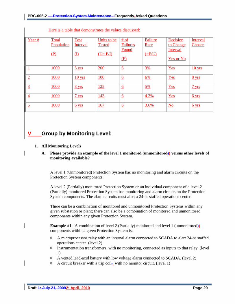
PRC-005-2 — Protection System Maintenance - Frequently-Asked Questions
Draft 1: July 21, 20092: April, 2010 Page 29
Here is a table that demonstrates the values discussed:
Year # Total Population
(P)
Test Interval
(I)
Units to be Tested
(U= P/I)
# of Failures Found
(F)
Failure Rate
(=F/U)
Decision to Change Interval
Yes or No
Interval Chosen
1 1000 5 yrs 200 6 3% Yes 10 yrs
2 1000 10 yrs 100 6 6% Yes 8 yrs
3 1000 8 yrs 125 6 5% Yes 7 yrs
4 1000 7 yrs 143 6 4.2% Yes 6 yrs
5 1000 6 yrs 167 6 3.6% No 6 yrs
V Group by Monitoring Level:
1. All Monitoring Levels
A. Please provide an example of the level 1 monitored (unmonitored)) versus other levels of monitoring available?
A level 1 (Unmonitored) Protection System has no monitoring and alarm circuits on the Protection System components. A level 2 (Partially) monitored Protection System or an individual component of a level 2 (Partially) monitored Protection System has monitoring and alarm circuits on the Protection System components. The alarm circuits must alert a 24-hr staffed operations center.
There can be a combination of monitored and unmonitored Protection Systems within any given substation or plant; there can also be a combination of monitored and unmonitored components within any given Protection System. Example #1: A combination of level 2 (Partially) monitored and level 1 (unmonitored)) components within a given Protection System is:
◊ A microprocessor relay with an internal alarm connected to SCADA to alert 24-hr staffed operations center. (level 2)
◊ Instrumentation transformers, with no monitoring, connected as inputs to that relay. (level 1)
◊ A vented lead-acid battery with low voltage alarm connected to SCADA. (level 2) ◊ A circuit breaker with a trip coil,, with no monitor circuit. (level 1)
PRC-005-2 — Protection System Maintenance - Frequently-Asked Questions
Draft 1: July 21, 20092: April, 2010 Page 30
Given the particular components, conditions, and using the Table 1 (“Maximum Allowable Testing Intervals and Maintenance Activities”), the particular components have maximum test intervals of:
◊ The microprocessor relay is verified every 12 calendar years. ◊ The instrumentation transformers are verified every 12 calendar years. ◊ The battery is verified every 6 calendar years by performing a performance capacity test of
the entire battery bank or by evaluating the measured cell/unit internal ohmic values to station battery baseline every 18 months.
◊ The circuit breaker trip circuits and auxiliary relays are tested every 6 calendar years. Example #2: A combination of level 2 (partially) monitored and level 1 (unmonitored)) components within a given Protection System is:
◊ A microprocessor relay with integral alarm that is not connected to SCADA. (level 1) ◊ Instrument transformers, with no monitoring, connected as inputs to that relay. (level 1) ◊ A vented lead-acid battery with low voltage alarm connected to SCADA. (level 2) ◊ A circuit breaker with a trip coil,, with no circuits monitored. (level 1) Given the particular components, conditions, and using the Table 1 (“Maximum Allowable Testing Intervals and Maintenance Activities”), the particular components have maximum test intervals of:
◊ The microprocessor relay is verified every 6 calendar years. ◊ The instrumentation transformers are verified every 12 calendar years. ◊ The battery is verified every 6 calendar years by performing a performance capacity test of
the entire battery bank or by evaluating the measured cell/unit internal ohmic values to station battery baseline every 18 months.
◊ The circuit breaker trip circuits and auxiliary relays are tested every 6 calendar years. Example #3: A combination of level 2 (partially) monitored and level 1 (unmonitored)) components within a given Protection System is:
◊ A microprocessor relay with alarm connected to SCADA to alert 24-hr staffed operations center. (level 2)
◊ Instrument transformers, with no monitoring, connected as inputs to that relay (level 1) ◊ Battery without any alarms connected to SCADA (level 1) ◊ Circuit breaker with a trip coil,, with no circuits monitored (level 1) Given the particular components, conditions, and using the Table 1 (“Maximum Allowable Testing Intervals and Maintenance Activities”), the particular components shall have maximum test intervals of: ◊ The microprocessor relay is verified every 12 calendar years. ◊ The instrument transformers are verified every 12 calendar years. ◊ The battery is verified every 3 months, every 18 months, plus, depending upon the type of
battery used it may be verified at other maximum test intervals, as well. ◊ The circuit breaker trip circuits and auxiliary relays are tested every 6 calendar years.
B. What is the intent behind the different levels of monitoring?
The intent behind different levels of monitoring is to allow less frequent manual intervention when more information is known about the condition of Protection System components.

PRC-005-2 — Protection System Maintenance - Frequently-Asked Questions
Draft 1: July 21, 20092: April, 2010 Page 31
C. Do all monitoring levels apply to all components in a protection system?
No. For some components in a protection system, certain levels of monitoring will not be relevant. See table below:
D. My microprocessor relays and dc circuit alarms are contained on relay panels in a 24-hour attended control room. Does this qualify as an extended time interval condition-based system?
Yes, provided the station attendant monitors the alarms and other indications and reports them within the given time limits that are stated in the criteria of the Table 1b or Table 1c.
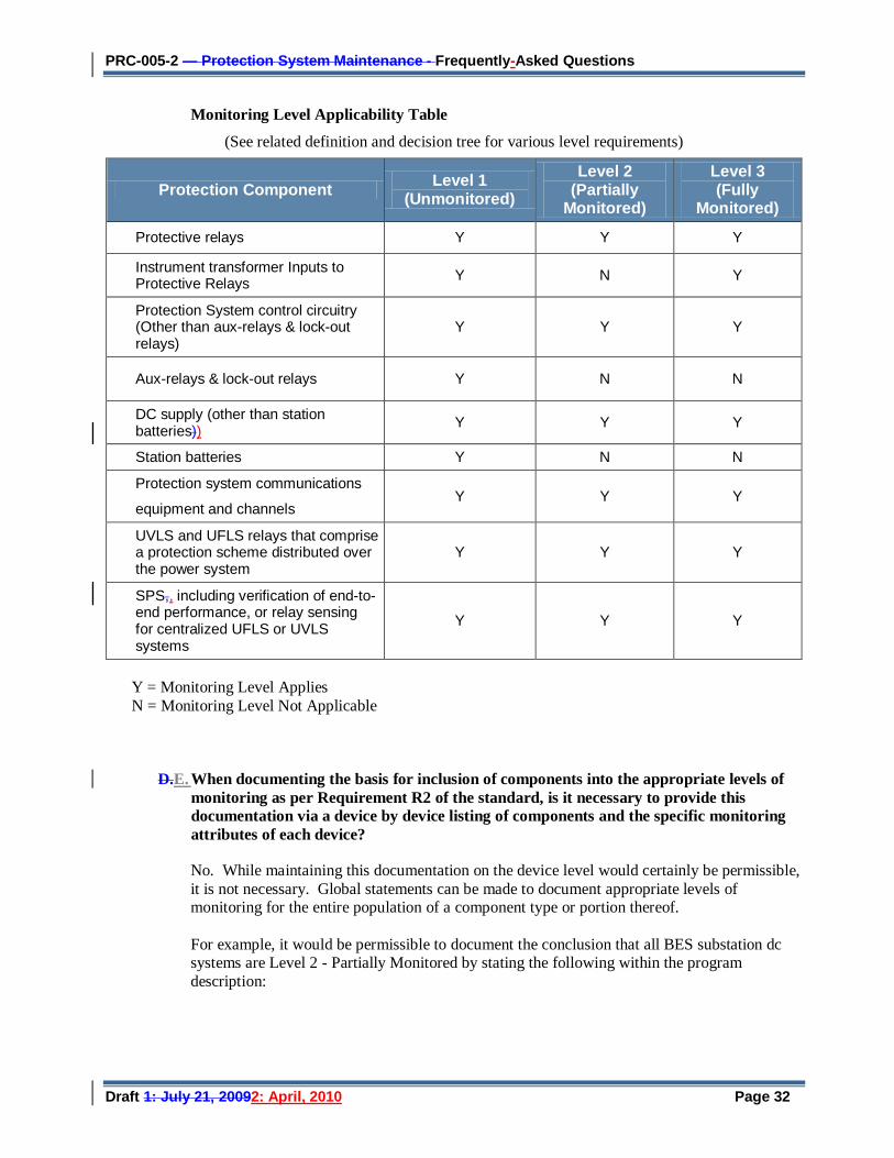
PRC-005-2 — Protection System Maintenance - Frequently-Asked Questions
Draft 1: July 21, 20092: April, 2010 Page 32
Monitoring Level Applicability Table
(See related definition and decision tree for various level requirements)
Y = Monitoring Level Applies N = Monitoring Level Not Applicable
D.E. When documenting the basis for inclusion of components into the appropriate levels of monitoring as per Requirement R2 of the standard, is it necessary to provide this documentation via a device by device listing of components and the specific monitoring attributes of each device?
No. While maintaining this documentation on the device level would certainly be permissible, it is not necessary. Global statements can be made to document appropriate levels of monitoring for the entire population of a component type or portion thereof. For example, it would be permissible to document the conclusion that all BES substation dc systems are Level 2 - Partially Monitored by stating the following within the program description:
Protection Component Level 1 (Unmonitored)
Level 2 (Partially
Monitored)
Level 3 (Fully
Monitored)
Protective relays Y Y Y
Instrument transformer Inputs to Protective Relays Y N Y
Protection System control circuitry (Other than aux-relays & lock-out relays)
Y Y Y
Aux-relays & lock-out relays Y N N
DC supply (other than station batteries)) Y Y Y
Station batteries Y N N
Protection system communications
equipment and channels Y Y Y
UVLS and UFLS relays that comprise a protection scheme distributed over the power system
Y Y Y
SPS,, including verification of end-to-end performance, or relay sensing for centralized UFLS or UVLS systems
Y Y Y
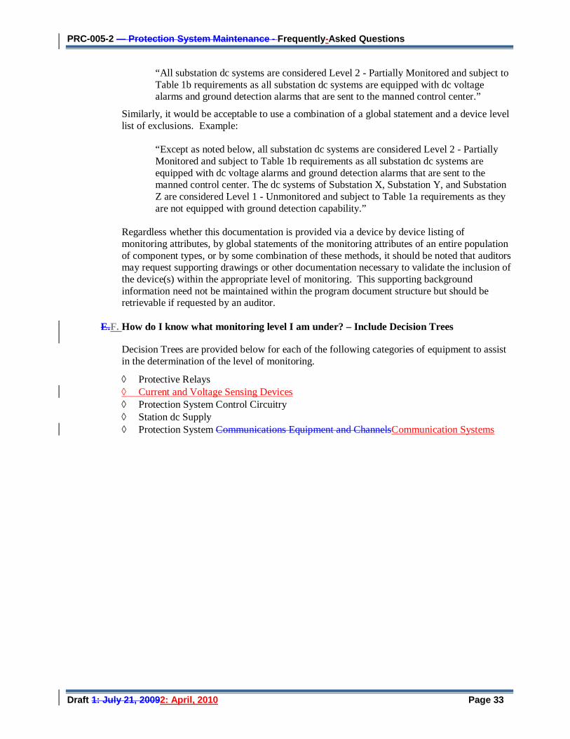
PRC-005-2 — Protection System Maintenance - Frequently-Asked Questions
Draft 1: July 21, 20092: April, 2010 Page 33
“All substation dc systems are considered Level 2 - Partially Monitored and subject to Table 1b requirements as all substation dc systems are equipped with dc voltage alarms and ground detection alarms that are sent to the manned control center.”
Similarly, it would be acceptable to use a combination of a global statement and a device level list of exclusions. Example:
“Except as noted below, all substation dc systems are considered Level 2 - Partially Monitored and subject to Table 1b requirements as all substation dc systems are equipped with dc voltage alarms and ground detection alarms that are sent to the manned control center. The dc systems of Substation X, Substation Y, and Substation Z are considered Level 1 - Unmonitored and subject to Table 1a requirements as they are not equipped with ground detection capability.”
Regardless whether this documentation is provided via a device by device listing of monitoring attributes, by global statements of the monitoring attributes of an entire population of component types, or by some combination of these methods, it should be noted that auditors may request supporting drawings or other documentation necessary to validate the inclusion of the device(s) within the appropriate level of monitoring. This supporting background information need not be maintained within the program document structure but should be retrievable if requested by an auditor.
E.F. How do I know what monitoring level I am under? – Include Decision Trees
Decision Trees are provided below for each of the following categories of equipment to assist in the determination of the level of monitoring.
◊ Protective Relays ◊ Current and Voltage Sensing Devices ◊ Protection System Control Circuitry ◊ Station dc Supply ◊ Protection System Communications Equipment and ChannelsCommunication Systems
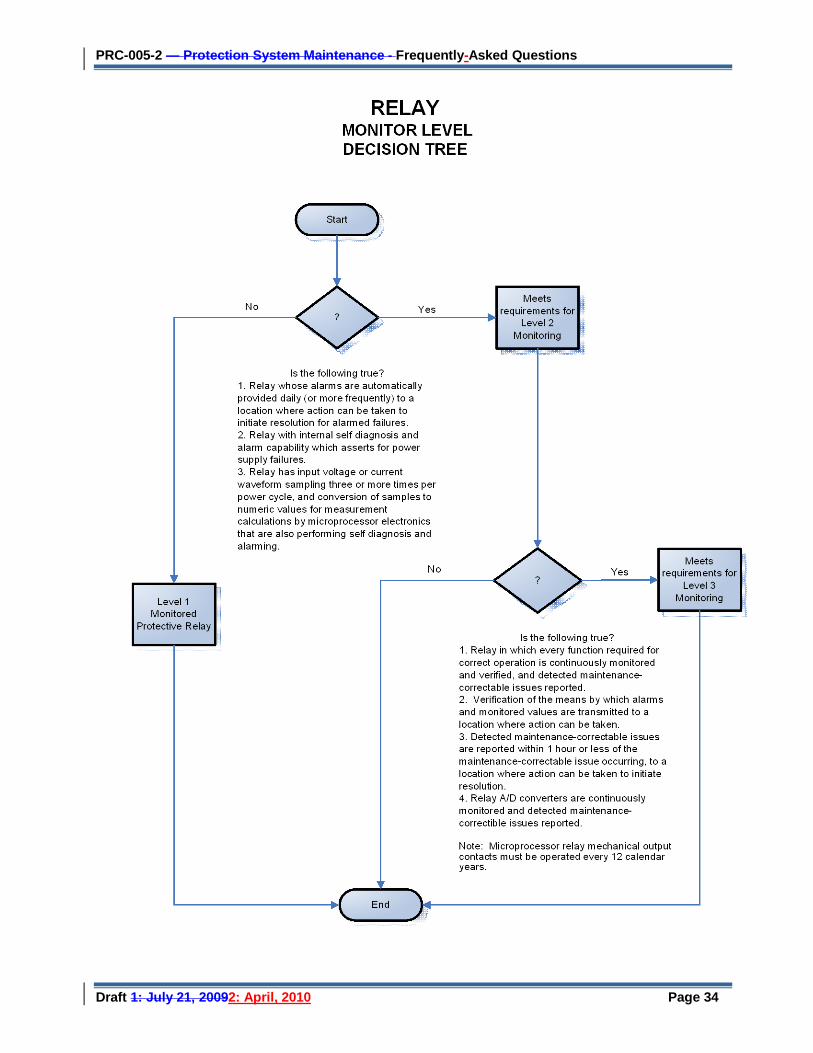
PRC-005-2 — Protection System Maintenance - Frequently-Asked Questions
Draft 1: July 21, 20092: April, 2010 Page 34
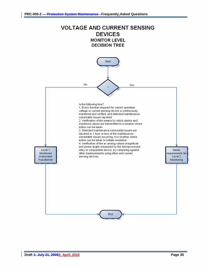
PRC-005-2 — Protection System Maintenance - Frequently-Asked Questions
Draft 1: July 21, 20092: April, 2010 Page 35
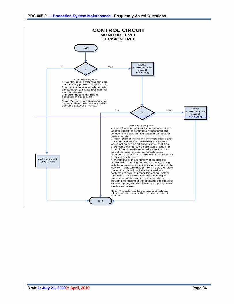
PRC-005-2 — Protection System Maintenance - Frequently-Asked Questions
Draft 1: July 21, 20092: April, 2010 Page 36
Start
Meets requirements for
Level 2 Monitoring
?
?
Meets requirements for
Level 3 Monitoring
End
Level 1 Monitored Control Circuit
Yes
Yes
No
No
CONTROL CIRCUIT MONITOR LEVELDECISION TREE
Is the following true?1. Control Circuit whose alarms are automatically provided daily (or more frequently) to a location where action can be taken to initiate resolution for alarmed failures. 2. Monitoring and alarming of continuity of trip circuit(s).
Note: Trip coils, auxiliary relays, and lock-out relays must be electrically operated at Level 1 interval.
Is the following true?1. Every function required for correct operation of Control Cirucuit is continuously monitored and verified, and detected maintenance-correctable issues reported.2. Verification of the means by which alarms and monitored values are transmitted to a location where action can be taken to initiate resolution.3. Detected maintenance-correctable issues for Control Circuit are be reported within 1 hour or less of the maintenance-correctable issue occurring, to a location where action can be taken to initiate resolution. 4. Monitoring of the continuity of breaker trip circuits (with alarming for non-continuity), along with the presence of tripping voltage supply all the way from relay terminals (or from inside the relay) though the trip coil, including any auxiliary contacts essential to proper Protection System operation. If a trip circuit comprises multiple paths, each of the paths must be monitored, including monitoring of the operating coil circuit(s) and the tripping circuits of auxiliary tripping relays and lockout relays.
Note: Trip coils, auxiliary relays, and lock-out relays must be electrically operated at Level 1 interval.
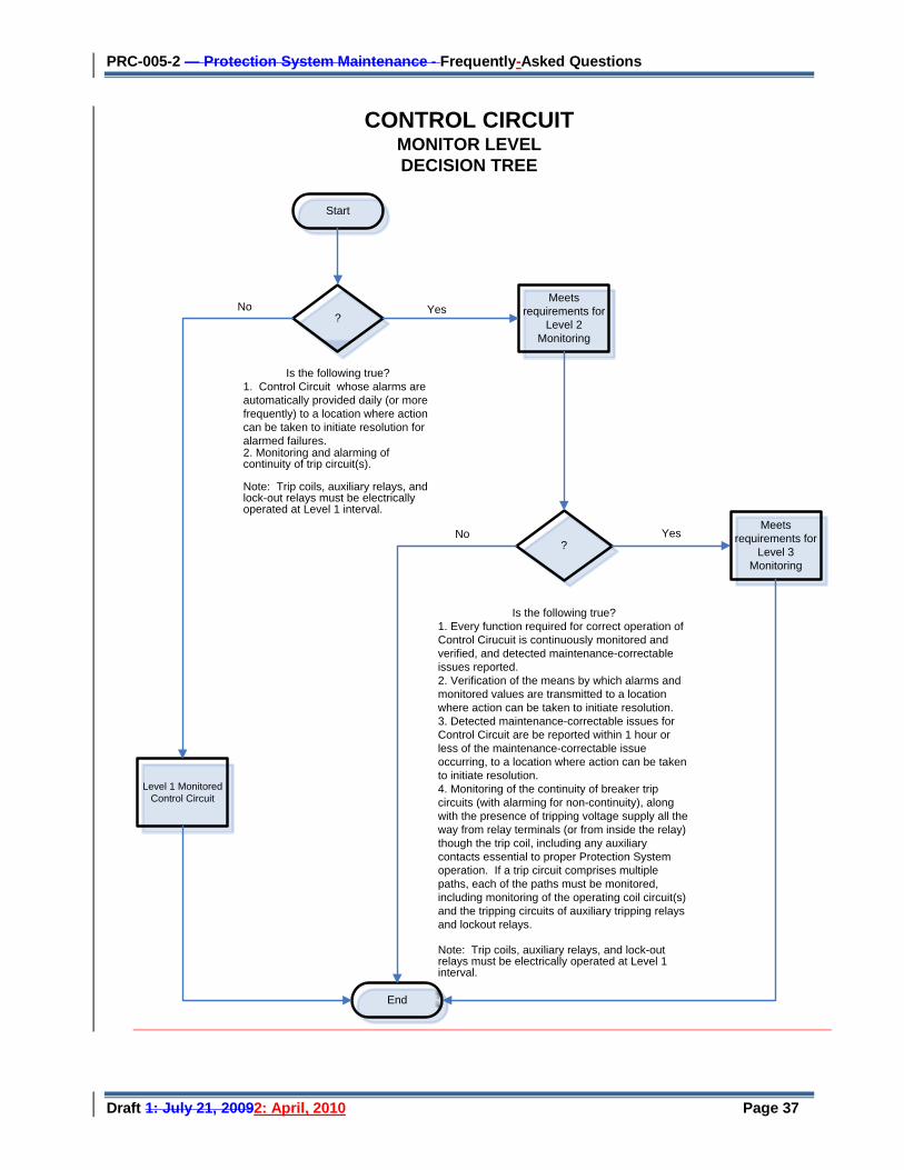
PRC-005-2 — Protection System Maintenance - Frequently-Asked Questions
Draft 1: July 21, 20092: April, 2010 Page 37
Start
Meets requirements for
Level 2 Monitoring
?
?
Meets requirements for
Level 3 Monitoring
End
Level 1 Monitored Control Circuit
Yes
Yes
No
No
CONTROL CIRCUIT MONITOR LEVELDECISION TREE
Is the following true?1. Control Circuit whose alarms are automatically provided daily (or more frequently) to a location where action can be taken to initiate resolution for alarmed failures. 2. Monitoring and alarming of continuity of trip circuit(s).
Note: Trip coils, auxiliary relays, and lock-out relays must be electrically operated at Level 1 interval.
Is the following true?1. Every function required for correct operation of Control Cirucuit is continuously monitored and verified, and detected maintenance-correctable issues reported.2. Verification of the means by which alarms and monitored values are transmitted to a location where action can be taken to initiate resolution.3. Detected maintenance-correctable issues for Control Circuit are be reported within 1 hour or less of the maintenance-correctable issue occurring, to a location where action can be taken to initiate resolution. 4. Monitoring of the continuity of breaker trip circuits (with alarming for non-continuity), along with the presence of tripping voltage supply all the way from relay terminals (or from inside the relay) though the trip coil, including any auxiliary contacts essential to proper Protection System operation. If a trip circuit comprises multiple paths, each of the paths must be monitored, including monitoring of the operating coil circuit(s) and the tripping circuits of auxiliary tripping relays and lockout relays.
Note: Trip coils, auxiliary relays, and lock-out relays must be electrically operated at Level 1 interval.
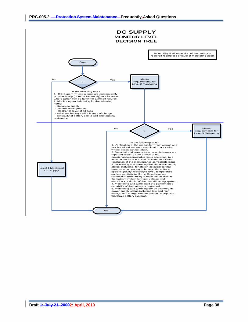
PRC-005-2 — Protection System Maintenance - Frequently-Asked Questions
Draft 1: July 21, 20092: April, 2010 Page 38
Start
Meets requirements for
Level 2 Monitoring
?
?
Meets requirements for
Level 3 Monitoring
End
Level 1 Monitored DC Supply
Yes
Yes
No
No
DC SUPPLY MONITOR LEVELDECISION TREE
Is the following true?1. DC Supply whose alarms are automatically provided daily (or more frequently) to a location where action can be taken for alarmed failures. 2. Monitoring and alarming for the following items: - station dc supply - unintential dc grounds - electrolyte level of all cells - individual battery cell/unit state of charge - continuity of battery cell-to-cell and terminal resistance
Is the following true?1. Verification of the means by which alarms and monitored values are transmitted to a location where action can be taken.2. Detected maintenance-correctable issues are reported within 1 hour or less of the maintenance-correctable issue occurring, to a location where action can be taken to inititate resolution of the maintenance correctable issue.3. Monitoring and alarming the station dc supply status, including, for station dc supplies that have as a component a battery, the voltage, specific gravity, electrolyte level, temperature and connectivity (cell to cell and terminal connection resistance) of each cell as well as the battery system terminal voltage and electrical continuity of the overall battery system. 4. Monitoring and alarming if the performance capability of the battery is degraded.5. Monitoring and alarming the ac powered dc power supply status including low and high voltage and charge rate for station dc supplies that have battery systems.
Note: Physical inspection of the battery is required regardless of level of monitoring used.
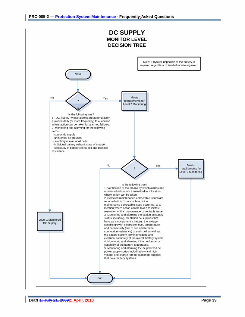
PRC-005-2 — Protection System Maintenance - Frequently-Asked Questions
Draft 1: July 21, 20092: April, 2010 Page 39
Start
Meets requirements for
Level 2 Monitoring
?
?
Meets requirements for
Level 3 Monitoring
End
Level 1 Monitored DC Supply
Yes
Yes
No
No
DC SUPPLY MONITOR LEVELDECISION TREE
Is the following true?1. DC Supply whose alarms are automatically provided daily (or more frequently) to a location where action can be taken for alarmed failures. 2. Monitoring and alarming for the following items: - station dc supply - unintential dc grounds - electrolyte level of all cells - individual battery cell/unit state of charge - continuity of battery cell-to-cell and terminal resistance
Is the following true?1. Verification of the means by which alarms and monitored values are transmitted to a location where action can be taken.2. Detected maintenance-correctable issues are reported within 1 hour or less of the maintenance-correctable issue occurring, to a location where action can be taken to inititate resolution of the maintenance correctable issue.3. Monitoring and alarming the station dc supply status, including, for station dc supplies that have as a component a battery, the voltage, specific gravity, electrolyte level, temperature and connectivity (cell to cell and terminal connection resistance) of each cell as well as the battery system terminal voltage and electrical continuity of the overall battery system. 4. Monitoring and alarming if the performance capability of the battery is degraded.5. Monitoring and alarming the ac powered dc power supply status including low and high voltage and charge rate for station dc supplies that have battery systems.
Note: Physical inspection of the battery is required regardless of level of monitoring used.
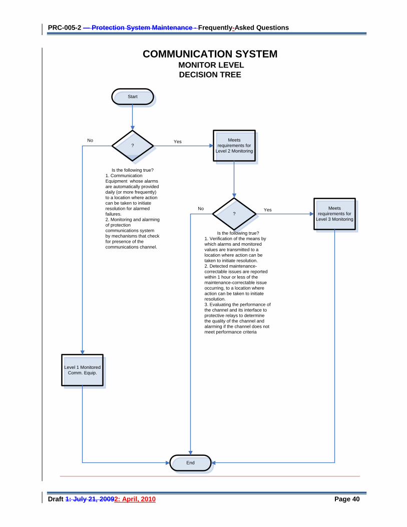
PRC-005-2 — Protection System Maintenance - Frequently-Asked Questions
Draft 1: July 21, 20092: April, 2010 Page 40
Start
Meets requirements for
Level 2 Monitoring
?
Is the following true?1. Communication Equipment whose alarms are automatically provided daily (or more frequently) to a location where action can be taken to initiate resolution for alarmed failures. 2. Monitoring and alarming of protection communications system by mechanisms that check for presence of the communications channel.
?
Is the following true?1. Verification of the means by which alarms and monitored values are transmitted to a location where action can be taken to initiate resolution.2. Detected maintenance-correctable issues are reported within 1 hour or less of the maintenance-correctable issue occurring, to a location where action can be taken to initiate resolution.3. Evaluating the performance of the channel and its interface to protective relays to determine the quality of the channel and alarming if the channel does not meet performance criteria
Meets requirements for
Level 3 Monitoring
End
Level 1 Monitored Comm. Equip.
Yes
Yes
No
No
COMMUNICATION SYSTEM MONITOR LEVELDECISION TREE
PRC-005-2 — Protection System Maintenance - Frequently-Asked Questions
Draft 1: July 21, 20092: April, 2010 Page 41
2. Level 1 Monitored Protection Systems (Unmonitored Protection Systems)
A. We have an electromechanical (unmonitored)) relay that has a trip output to a lockout relay (unmonitored) which trips our transformer off-line by tripping the transformer’s high-side and low-side circuit breakers. What testing must be done for this system?
This system is made up of components that are level 1 (unmonitored).). Assuming a time-based protection system maintenance program schedule, each component must be maintained per Table 1a – Level 1 Monitoring Maximum Allowable Testing Intervals and Maintenance Activities.
3. Level 2 Monitored Protection Systems (Partially Monitored Protection Systems)
A. We have a 30 year old oil circuit breaker with a red indicating lamp on the substation relay panel that is illuminated only if there is continuity through the breaker trip coil.. There is no SCADA monitor or relay monitor of this trip coil. The line protection relay package that trips this circuit breaker is a microprocessor relay that has an integral alarm relay that will assert on a number of conditions that includes a loss of power to the relay. This alarm contact connects to our SCADA system and alerts our 24-hour operations center of relay trouble when the alarm contact closes. This microprocessor relay trips the circuit breaker only and does not monitor trip coil continuity or other things such as trip current. Is this an unmonitored or a partially-monitored system? How often must I perform maintenance?
The protective relay is a level 2 (partially) monitored component of your protection system and can be maintained every 12 years or when a maintenance correctable issue arises. Assuming a time-based protection system maintenance program schedule, this component must be maintained per Table 1b – Level 2 Monitoring Maximum Allowable Testing Intervals and Maintenance Activities
The rest of your protection system contains components that are level 1 (unmonitored)) and must be maintained within at least the maximum verification intervals of Table 1a..
B. How do I verify the A/D converters of microprocessor--based relays?
There are a variety of ways to do this. Examples include using values gathered via data communications and automatically comparing these values with values from other sources, and using groupings of other measurements (such as vector summation of bus feeder currents) for comparison if calibration requirements assure acceptable measurement of power system input values. Other methods are possible.
C. For a level 2 monitored Protection System (Partially Monitored Protection System) pertaining to Protection System communications equipment and channels, how is the performance criteria involved in the maintenance program?
The entity determines the performance criteria for each installation, depending on the technology implemented. If the communication channel performance of a Protection System varies from the pre-determined performance criteria for that system, these results should be investigated and resolved.
PRC-005-2 — Protection System Maintenance - Frequently-Asked Questions
Draft 1: July 21, 20092: April, 2010 Page 42
D. My system has alarms that are gathered once daily through an auto-polling system; this is not really a conventional SCADA system but does it meet the Table 1b requirements for inclusion as Level 2?
Yes, provided the auto-polling that gathers the alarms reports those alarms to a location where the action can be initiated to correct the maintenance-correctable issue. This location does not have to be the location of the engineer or the technician that will eventually repair the problem, but rather a location where the action can be initiated.
4. Level 3 Monitored Protection Systems (Fully Monitored Protection Systems)
A. Why are there activities defined for a level-3 monitored Protection System? The technology does not seem to exist at this time to implement this monitoring level.
There may actually be some equipment available that is capable of meeting level-3 monitoring criteria, in which case it may be maintained according to Table 1c.
. However, even if there is no equipment available today that can meet this level of monitoring,; the Standard establishes the necessary requirements for when such equipment becomes available. By creating a roadmap for development, this provision makes the Standard technology-neutral. The standard drafting team wants to avoid the need to revise the Standard in a few years to accommodate technology advances that are certainly coming to the industry.
PRC-005-2 — Protection System Maintenance - Frequently-Asked Questions
Draft 1: July 21, 20092: April, 2010 Page 43
Appendix A — Pro tec tion Sys tem Main tenance S tandard Dra fting Team
Charles W. Rogers
Chairman Consumers Energy Co.
John B. Anderson Xcel Energy Merle E. Ashton Tri-State Transmission and Generation CooperativeG&T Bob Bentert Florida Power & Light Company Al Calafiore NERC Staff North American Electric Reliability Corporation John Ciufo Hydro One Inc Richard Ferner Western Area Power Administration Sam Francis Oncor Carol A Gerou Midwest Reliability Organization Roger D Greene William Shultz Southern Company Generation Russell C Hardison Tennessee Valley Authority David Harper NRG Texas Maintenance Services John Kruse
Mark Lukas ComEd Al McMeekin NERC Staff North American Electric Reliability Corporation Mark Peterson Great River Energy William Shultz Southern Company Generation Leonard Swanson, Jr National Grid USA Eric A Udren Quanta Technology Philip B Winston Georgia Power Company John A Zipp ITC Holdings

PRC-005-2 — Protection System Maintenance - Frequently-Asked Questions
Draft 1: July 21, 20092: April, 2010 Page 44
Index
3-month interval, 24
aggregate, 24, 25
alarm, 16, 17, 18, 29, 30, 38
automated monitoring and alarming, 24
auto-restoration, 5
auxiliary relay, 11
batteries, 12, 13, 14, 15, 26, 27, 31
battery, 10, 12, 13, 14, 15, 26, 27, 29, 30
broken, 7
capacity, 14, 15, 29, 30
channel performance, 18, 38
charger, 12, 13, 14
check-off, 15
closing circuits, 5
commission, 23
Communication Site Batteries, 15
communications, 7, 11, 16, 17, 18, 31, 38
communications channel, 16, 17
communications-assisted-trip, 11
component, 2, 5, 11, 14, 19, 22, 23, 25, 26, 29, 31, 32, 38
continuity, 12, 13, 14, 38
corrective, 2, 5, 26
countable events, 2, 25
current and voltage measurements, 9
data retention, 22
DC ground, 15
documentation, 6, 21, 23, 31, 32
documentation method, 15
electromechanical, 7, 10, 26, 38
electro-mechanical relays, 6
evidence, 6, 22
fiber optic I/O scheme, 17
firmware, 5, 25
frequency-shift, 16
fully monitored, 16, 21
guard, 16, 17
Level 1, 16, 17, 31, 32, 38
Level 2, 16, 17, 31, 32, 38
Level 3, 16, 17, 27, 31, 39
lockout relay, 11, 20, 38
maintenance correctable issue, 2, 38
maintenance plan, 6, 22, 24
maximum allowable interval, 24, 26
microprocessor, 5, 6, 7, 9, 10, 11, 13, 14, 26, 29, 30, 38
Misoperations, 2, 25
nickel-cadmium, 14, 15
ohmic, 14, 15, 29, 30
out-of-service, 7
partially monitored, 11, 16
PBM, 24, 25, 26, 27
performance-based maintenance, 25, 26
pilot wire, 16
PMU, 19
power-line carrier, 16
pressure relays, 11, 12
protective relays, 5, 6, 7, 8, 10, 12, 13, 16, 18, 20
reclosing relays, 5
Restoration, 5
sample list of devices, 20
segment, 2, 24, 25, 26, 27
settings, 2, 6, 7, 12, 22
SPS, 5, 19, 31
Table 1a, 2, 3, 5, 23, 32, 38
Table 1b, 5, 11, 17, 32, 38
Table 1c, 2, 5, 21, 39
TBM, 22
trip coil, 10, 11, 29, 30, 38
PRC-005-2 — Protection System Maintenance - Frequently-Asked Questions
Draft 1: July 21, 20092: April, 2010 Page 45
trip signal, 11, 17
trip test, 11
tripping circuits, 10
UFLS, 18, 19, 31
unintentional ground, 15
unmonitored, 16, 29, 30, 38
UVLS, 18, 19, 31
valve-regulated lead-acid, 15
vented lead-acid, 15, 29
voltage and current sensing devices, 2, 8, 10
VRLA, 14, 15