frequency spectrum for new aviation data links: initial ... · the study focused on systems and...
TRANSCRIPT
Frequency Spectrum for New Aviation Data Links: Initial Study Results
David W. Matolak
School of Electrical Eng. & Comp. Science 322E Stocker Center
Ohio University Athens, OH 45701
phone: 740.593.1241 fax: 740.593.0007
email: [email protected]
James R. Branstetter
FAA Office of Aviation Research (AAR-210) NASA Langley Research Center
Hampton, VA 23681 phone: 757.864.6396
fax: 757.864.1908 email: [email protected]
Abstract
We describe results from an initial study to assess the suitability of various spectral bands for supporting the deployment of new aviation data links (ADL). The study focused on systems and spectral bands that can deliver VHF data link (VDL)-or-higher data rates in a two-way communication setting, including air-ground, ground-air, and air-air modes of operation. In the first part of our paper, we briefly discuss the current situation regarding communications, navigation, and surveillance (CNS) links and existing spectrum, and the well-known need for new aviation data links. We next provide an overview of related systems, and discuss key factors involved in the use of spectrum in various bands for any future integrated CNS data link, addressing primarily the lower few layers of the communications protocol stack. Desired attributes of a new ADL system are discussed, and the beneficial aspects of a particular transmission technique—spread spectrum—are summarized. We also provide a short list of several example potential spectral regions, and note that while none of the existing systems will likely meet the full range of desired features of a new ADL, several systems and spectral regions offer promise in terms of one or more characteristics. A detailed discussion and evaluation of these spectral regions is proposed as future work. We include a few brief examples to illustrate initial technical results regarding spread spectrum overlay, also a subject for future work. I. Introduction There have been many studies recently that document the need for additional communication capabilities in civilian aviation. For example, one
can cite the Federal Aviation Administration’s (FAA) National Airspace System (NAS) “modernization blueprint,” [1], any one of numerous papers from recent professional conferences in the field, such as the Digital Avionics Systems Conferences (DASC), e.g., [2], [3], or recent Integrated Communications, Navigation, and Surveillance (ICNS) workshops, e.g., [4], [5]. The growth of passenger communications is also expected [6]. Additional communication capabilities, along with additional navigation and surveillance capabilities, will require not only new technologies, but careful planning. The aim toward integration of these three functions (hence: ICNS) has initiated many studies on technology options, e.g., [7], [8], and many on planning efforts, e.g., [9], the report from which this paper derives. There are numerous issues associated with deploying any new data communication system, including interfacing with existing systems, system requirements definition, economics, etc. The region of frequencies—or spectrum—used by the system is a key issue, on which we focus here. Spectral allocation has a significant effect upon, and can be viewed as pre-determining, some of these issues. The initial areas of investigation in our work, directed at the physical and data link layers, were on spectrum availability and coexistence with current systems. In the spectrum availability area, our goal was to determine the amount of “free” spectrum, and any potential CNS spectrum that could be allocated to air traffic control (ATC) and air traffic management (ATM) communications on either a shared or dedicated basis, to accommodate both non-time-critical messages and more critical pilot-controller communications. In the coexistence area, the ultimate goal was to assess “intersystem”
https://ntrs.nasa.gov/search.jsp?R=20040139164 2018-07-13T11:23:09+00:00Z
interference issues in both directions, i.e., from new CNS on existing, and from existing on new CNS. In Section II we review some current related efforts. In Section III, we review key factors for consideration of a spectral region, and in Section IV we provide some discussion of desirable features of any spectral region for a new ADL. Section V provides a discussion of some potential spectral regions and a few example technical results. In Section VI we provide a summary and conclusions. II. Current Systems A. Next Generation Air Ground Communications (NEXCOM) The Next Generation Air Ground Communications (NEXCOM) program has been underway for several years in terms of R&D [10]. As described on the website, it is
…the Federal Aviation Administration's (FAA) radio system of the 21st century. It is an analog/digital system incorporating the latest technological advances in radio communications. NEXCOM will provide capability to accommodate additional sectors and services; reduce logistical costs; replace expensive to maintain VHF and UHF radios; provide data link communications capability; reduce A/G RF Interference and provide security mechanisms. When completed over 46,000 radios will be installed throughout the FAA system.
The NEXCOM program has several phases of implementation and refers to several potential radio modes; the radios will operate in the VHF aeronautical spectrum, from 118.0-137.0 MHz, using existing 25 kHz channels. The preferred radio mode is denoted VHF digital link (VDL) mode 3, offering both digital voice and data. The International Civil Aviation Organization (ICAO) has developed VDL Standards and Recommended Practices (SARPs) that define two additional VDL modes: Mode 1 using an MSK-AM modulation scheme providing a 2.4 kb/s data rate; and Mode 2 using a D8PSK modulation scheme providing a 31.5 kb/s data rate. The VDL2 system is a carrier sense-multiple access (CSMA) system that employs the same modulation as VDL3, differential 8-ary phase
shift keying (D8PSK). The VDL2 system is not part of NEXCOM [11]. The VDL3 system is designed for time division multiple access (TDMA) operation, for both voice and data, ultimately as a replacement for the current analog AM system that is used for pilot-controller two-way communications. The VDL2 applications are generally classified under the following general categories: Air Traffic Control (ATC), Flight Information Services (FIS), Aeronautical Operational Control (AOC). Reference [9] gives a brief summary of some of the attributes of the VDL3 system. The data rates available with VDL3 are modest: per all four timeslots, a maximum of 19.2 kbps can be attained. B. Small Aircraft Transportation System (SATS) The Small Aircraft Transportation System (SATS) program is a joint FAA/NASA program to explore future means of air transportation with small aircraft. The initial work is focused on research and development of some of the technologies needed for SATS [12]: “the project's initial focus is to prove that four new operating capabilities will enable safe and affordable access to virtually any runway in the nation in most weather conditions. These new operating capabilities rely on on-board computing, advanced flight controls, Highway in the Sky displays, and automated air traffic separation and sequencing technologies.” The technologies referred to are actually composed of multiple subsystems beneath. We consider only the last one—automated air traffic separation and sequencing technologies. Clearly these must include communication systems, navigation systems, and surveillance systems (CNS), all of which must work together to ensure safety of all phases of flight. Recently, NASA (Glenn and Langley) reported successful demonstration of some “airborne internet” capabilities [13]. This demonstration was also presented at a prior ICNS conference (May 2003). The demonstration showed the feasibility of some of the required features of “airborne internet,” related to SATS. Yet, being a demonstration, it used VDL mode 4 radio technology for “research purposes” in developing the physical and lower layers. This was primarily because of the readily available and simple interface between the radio and common internet connections. The VDL mode 4 radios are not planned to be used in the US for any communication system.

As noted in [13], the next stage planned for this capability will be transfer of the demonstration system to one of the SATSLabs and the Airborne Internet Consortium (see below) for experimental evaluations and commercialization. These two steps (evaluation and commercialization) may require substantial changes to the demonstration system in terms of its components, capabilities, and modes of operation. That is, a final SATS airborne internet communication system (even the lowest few layers) will likely be substantially different from the demonstration system. A few items of interest in this study that could, or will likely change, include the following • frequency band of operation, • available data rates and channel bandwidths, • number of simultaneous users, • range and spatial discrimination. C. Universal Access Transceiver (UAT) The Universal Access Transceiver (UAT) system is, like NEXCOM, a set of technologies applicable to the lower few layers of the communications protocol stack. The UAT has been mostly applied to surveillance applications, in particular Automatic Dependent Surveillance—Broadcast (ADS-B). In this application, it has been successfully deployed on a trial basis in Alaska. Plans for its use in the contiguous US may be underway. The UAT system uses a fairly simple binary modulation, to enable reduction of aircraft radio costs. Like NEXCOM’s VDL3, it also uses time slotting, and burst transmissions, although the aircraft transmissions are not assigned to slots, but are randomly accessed [14] (this is also known as “Slotted ALOHA” random access). Multiple ground and airborne slots are available within each 1-second UAT frame period. The transmission rate is approximately 1 Mbps; with overhead and contention, the actual throughput is considerably less. For example, with ground transmission accounting for about 18% of each frame, with the Slotted ALOHA technique, the actual throughput (counting header and other overhead per each packet) would be approximately 0.36(0.82)1Mbps≅295 kbps, when packet collisions and retransmissions are accounted for. If more structured time slot allocations were imposed, the throughput could increase by approximately a factor of three (gaining back the Slotted ALOHA
degradation). Clearly, the transmission technique of UAT itself is not as limiting in terms of data rate as is VDL3. In addition, the UAT transceivers do not (yet!) have to operate in more than a single mode, and hence can be less complex and less expensive. With their wider bandwidths, they are less spectrally efficient, but given their simpler design and more recent development, they could likely be more easily modified. The RTCA [15] is currently developing standards for UAT, and the FAA has a working group site for this [16]. The inability of the current UAT transceivers to provide individual message addressing and true peer-to-peer connectivity is one of the shortfalls of UAT for use in a new ADL system. In addition (like VDL3), no specific enhancements or features for robustness or strong security are provided in UAT. In [9], a set of summary UAT parameters is provided. D. Alternative Systems As can be said of waveforms, it makes good sense to take advantage of the knowledge and techniques applicable to systems designed for other applications. One example is terrestrial cellular radio, for which at least three standards are currently in use worldwide: frequency division multiple access (FDMA) with analog FM modulation (the advanced mobile phone system, AMPS), time division multiple access (TDMA) with narrowband digital modulation (digital amps, DAMPS, or the Global System for Mobile communications, GSM), and code division multiple access (CDMA) with digital spread spectrum modulation (cdmaOne) [17]. In addition, new upgrades to these standards are in current development (and deployment, particularly in Japan). All these upgrades plan to employ CDMA. Other commercial systems of interest include the wireless LAN standards, mostly overseen by the IEEE as their “802” set of standards. The 802.11b standard is currently in widespread use, with a direct-sequence spread spectrum (DS-SS) transmission scheme that uses the 2.4 GHz unlicensed band. It is capable of offering data rates up to 11 Mbps for short range applications. The 802.11a standard is currently nearly mature, with a form of spectral spreading (orthogonal frequency division multiplexing, OFDM) for the 5.8 GHz unlicensed band, with data rates up to approximately 50 Mbps, also for short range applications. A new 802 standard is also being developed, the 802.20

standard, aimed at data rates comparable to those of the 802.11a standard, but for high-speed mobile platforms. Finally, systems and techniques used in the military (aeronautical or otherwise) are of interest, in particular for security and robustness. III. Key Factors in Spectrum Selection For aeronautical applications, we list some key factors that must be considered if any new CNS service/system is to be deployed. These well-known factors are radio propagation, technology availability, availability of spectrum, and waveforms. We also discuss relevant alternative (non-aeronautical) systems. As would be expected, these factors are intricately inter-related, and study of one generally leads to study of others. A. Propagation As is well known, propagation in the lower atmosphere undergoes a loss due to wavefront “spreading,” proportional to carrier frequency. Hence for a given value of transmit power, range decreases as carrier frequency increases. Use of VHF, UHF, and SHF bands are most likely for any new ADL. For maximum range, VHF is preferable, but the drawback is shortage of available aeronautical spectrum. In general, spectral bandwidths increase as carrier frequency increases. Depending upon concept of operations, the shorter range associated with the higher frequency bands can be addressed through use of (adaptive) directive antenna systems, extraordinarily strong FEC (e.g., “turbo” codes), or relay techniques. Another possibility is the use of different frequency bands for different services and different phases of flight. For example, during takeoff and landing, when aircraft are relatively close to ground stations, higher-bandwidth shorter-range bands such as SHF could be used, and during “enroute” higher altitude phases of flight, lower data rate VHF bands could be used. B. Technology Generally, the term technology is quite broad in terms of interpretation. We restrict our attention here to its use to describe the circuits, subsystems, and processing that are either readily available, or “nearly available.” An example of the latter is radio frequency components (e.g., amplifiers) being
developed for nascent wireless local area networks (LANs) in the 5.8 GHz unlicensed band. For reasons of economy, re-use of existing technologies is most attractive. For any new system design though, some modifications will be almost certain. Hence, it makes much sense to consider technologies being developed for other applications (discussed below). Many of these technologies (e.g., wireless LANs) are planning to offer very high data rates, multiple levels of QoS, and strong security. C. Spectrum Availability This issue may prove to be one of the most significant for any new ADL system. With the aeronautical spectrum at VHF nearly full, obtaining any new bands at VHF will require significant administrative support. Currently, some of the SHF band reserved for aeronautical use, specifically the microwave landing system (MLS) band at 5 GHz, is being targeted by other (non-aeronautical) users in both Europe and the US. Hence, it is in the best interest of the aeronautical community to deploy even a prototype ADL system in the MLS band, simply for the sake of maintaining control over this portion of spectrum. A second, more technical concern regards the coexistence of a new ADL system with any currently existing system. This will impact the ADL design in terms of out-of-band emissions, power levels, and spectral mask, and hence relates closely to the physical layer design. D. Waveforms The topic of waveforms is of course a physical layer one, and as noted, cannot be considered in isolation. Yet the state of digital wireless communications is fairly mature, so vast array of waveform choices is available, with mostly well-known characteristics, many of which are desirable and suitable for aeronautical applications. More will be said regarding waveforms in the subsection below on spread spectrum. IV. Desired New ADL System Attributes A. New ADL System Characteristics For widespread acceptance of any ADL system, the system must offer capabilities not present, or at

least not fully supported by existing systems. Generally, this would mean that the new ADL system should • offer higher data rates than existing systems, • be able to serve a large number of users “simultaneously” in any given geographic area (range for air-ground, ground-air, or air-air communications should be as large as possible), • ideally support peer peer connectivity, so that any aircraft could transmit/receive data to/from any other aircraft or ground site in range, • be able to support asymmetric services, i.e., services that require different data rates in the different directions of transmission, • allow for a wide variety of data rates and data traffic types, with differing requirements on message latency (delay) and integrity, • be reliable, which implies redundancy, • be secure in several ways (anti-spoof, anti-overload, anti-eavesdrop) • be affordable! The variety of data traffic types and quality is often cast in terms of Quality of Service (QoS) parameters: data rate (Rb), delay (τ), and error probability (e.g., Pb for bit error probability). A variety of message rates would enable the ADL system to be used for multiple purposes, which would enhance its acceptance.
B. Use of Spread Spectrum As alluded to, the use of spread spectrum (SS) transmission offers several advantages over narrowband transmission schemes. This is certainly one of the reasons that ALL the new terrestrial cellular standards will use SS [18], [19]. Generally, SS schemes are of two types: direct-sequence (DS) and frequency hopped (FH). Each has its own particular advantages/disadvantages, but both offer the following attractive properties: • Security: SS transmissions are difficult to eavesdrop on or “masquerade as” because of their use of platform-unique spreading codes. • Robustness: SS transmissions are resistant to interference, and can operate very well in distorting channel conditions • Capacity: in the cellular context, SS schemes, used in CDMA fashion, have proven superior to narrowband schemes in terms of the number of simultaneous users they can support.
• Flexibility: in many ways, the use of strong and variable-rate FEC, and the use of advanced detection techniques is facilitated via SS transmission. In addition, SS in various forms can be used simultaneously in the same spectrum with narrowband schemes. This is termed spectral overlay. Depending upon the actual bandwidth, SS transmissions can also be used for ranging (e.g., GPS is a spread spectrum system). During the development of SS CDMA for terrestrial cellular systems, it was initially presumed that the overall complexity of a CDMA system would prevent its deployment. This was proved incorrect, and the technologies required for effective SS transmission and reception are readily available. Also worthy of note is that the European aeronautical community is already conducting experiments with SS transmission [20]. Because of all the above qualities, SS is a good candidate for consideration in a new ADL system. C. Macro Diversity In addition to the points mentioned, for ultimate flexibility and reliability, the use of “macro diversity” could be considered. In this context, what is meant could also be termed adaptive “band hopping,” wherein given some end-to-end QoS requirements (at whatever layer), the radio system could adaptively select the appropriate band (subsystem) for transmission. This is related to the use of different frequency bands for different services and different phases of flight mentioned previously. For this approach to be feasible, not only will technology need to be adaptive, but spectral management will need to be dramatically generalized; the latter is likely the bigger challenge. V. Example Spectral Regions; Analytical Results A. Spectral Regions In this section we review some of the potential spectral regions that could support a new ADL system. While in principle there exist vast amounts of unused spectrum, at frequencies above those in common use (e.g., the V band around 45 GHz), the technologies are not presently available to economically deploy communication systems in these bands. As noted previously, propagation

conditions favor the use of lower frequencies for transmission ranges of interest in the aeronautical case (tens of meters to a few hundred kilometers). Hence we restricted our attention to frequency bands below Ku band (12 GHz), at least for ground-air and air-air communications. For satellite systems, it may be possible to use the higher frequency bands. For the lower frequency limit, we selected the upper limit of the HF band, equal to the lower limit of the VHF band, approximately 30 MHz. This is primarily because to support multiple users with data rates on the order of 100kbps or more requires more bandwidth than is available with channels in the HF band and below. Hence, we focus on the VHF, UHF, and SHF bands. Because of the very high demand for spectrum in these bands, it is also most likely that any new ADL system will be deployed in spectrum already dedicated to aeronautical applications, either communications or otherwise. This may seem problematic, and it is likely that any current users of a band will need substantial experimental proof that their services will not be significantly degraded; yet, the actual duty cycle of usage of most spectral regions in most spatial areas is lower than one might expect [21]. As noted in [21], for many commercial and military spectral allocations, actual spectral occupancy by signals varies considerably in both time and space, with significant “gaps” available in both these dimensions. Even without exploitation of
such gaps, more efficient use of spectrum is definitely possible. One method of some recent research interest (e.g., [22]) is spectral overlay of direct-sequence spread spectrum upon narrowband signal spectra. We provide some example results for this approach in the next subsection [23], [24]. Thus far we have surveyed several candidate spectral bands, but more study is required to fully characterize all options. We have aimed at providing both some breadth, and some depth, the latter of which is exemplified by the examples that follow. The key systems/spectral regions we have considered here are briefly described in Table 1. The systems listed in Table 1 are very different in terms of communication parameters and application. In [9] we list more completely some of the lower layer communications protocol stack parameters for four of the systems of Table 1. B. Example Analysis Results We provide some example results from [23] and [24]. These studies explored the feasibility of using two existing aeronautical bands—the ILS and MLS bands—for a new ADL that used spectral overlay. Spectral overlay is the simultaneous use of common spectrum by multiple signals, usually of disparate bandwidths. Direct-sequence spread-spectrum (DS-SS) was assumed in both cases,
Table 1. Example potential systems/spectra for a new ADL system.
System or Spectrum
Frequency Band
Comments
VDLM3 118-137 MHz FAA choice for digital voice and data. Data rate limited. Keeping only 25 kHz channel bandwidths implies only moderate data rate achievable.
ILS Glideslope
329-335 MHz Only approximately 5 MHz spectrum, but good propagation conditions. Coexistence with tone-modulated ILS signal is biggest challenge.
Universal Access Transceiver (UAT)
Two 1 MHz channels: 971 MHz
(CONUS), 981 MHz (Alaska)
Developed in FAA Capstone (ADS-B) project. Only two channels currently; design modifications needed for increased data rates. Peer-peer user addressing not currently available.
Military UHF
225-328.6 MHz 335.4-399.9
MHz
Existing transceivers very high power, making coexistence very challenging. Commercial use of military spectrum is likely a large administrative and political challenge.
Microwave Landing System (MLS)
5-5.25 GHz MLS not deployed widely. Technologies for this band less mature, but very wide bandwidth available. Propagation conditions may dictate use of directive antennas, and/or use in shorter range conditions.
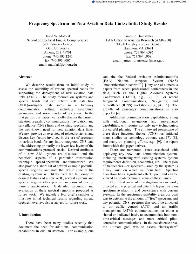
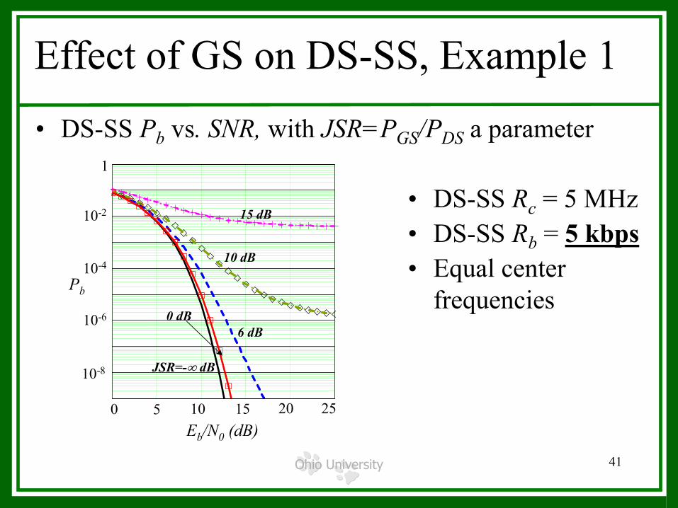
which explored the mutual effects of the overlaying signals upon each other. Worth noting is that the use of overlay is something of a worst case for these systems, and it might only be used in extreme cases. The use of orthogonal (non-overlapping) spectral regions for these signals is easier to manage, and provides generally better performance in terms of error probability—it may not provide a higher data throughput. In any case, if overlay can be done, orthogonal spectral allocations can be done more easily. The first result in Figure 1 shows DS-SS BER as a function of SNR for several different values of JSR, in the ILS band. Here, JSR is the ratio of the ILS signal power to the DS-SS signal power at the DS-SS receiver. In this figure, the chip rate of the DS-SS system is 5 MHz, and the bit rate of the DS-SS system is 50 kbps. If for example the DS-SS system requires an error probability of no greater than 10-3, the maximum acceptable JSR is between 10 dB and 15 dB.
0 5 10 15 20 251 .10 9
1 .10 8
1 .10 7
1 .10 6
1 .10 5
1 .10 4
1 .10 3
0.01
0.1
10.339
10 9−
Pb 30− Eb, 100, Rc,( )
Pb 10 Eb, 100, Rc,( )
Pb 15 Eb, 100, Rc,( )
Pb 20 Eb, 100, Rc,( )
Pb 25 Eb, 100, Rc,( )
Pb 30 Eb, 100, Rc,( )
Pb 0 Eb, 100, Rc,( )
250 Eb
10-4
10-8
0.01
1
10-6
Pb
SNR (dB)0 5 10 15 20 25
JSR=-∞ dB
JSR=20 dB
JSR=15 dB
JSR=10 dB
JSR=30 dB
JSR=0 dB
0 5 10 15 20 251 .10 9
1 .10 8
1 .10 7
1 .10 6
1 .10 5
1 .10 4
1 .10 3
0.01
0.1
10.339
10 9−
Pb 30− Eb, 100, Rc,( )
Pb 10 Eb, 100, Rc,( )
Pb 15 Eb, 100, Rc,( )
Pb 20 Eb, 100, Rc,( )
Pb 25 Eb, 100, Rc,( )
Pb 30 Eb, 100, Rc,( )
Pb 0 Eb, 100, Rc,( )
250 Eb0 5 10 15 20 251 .10 9
1 .10 8
1 .10 7
1 .10 6
1 .10 5
1 .10 4
1 .10 3
0.01
0.1
10.339
10 9−
Pb 30− Eb, 100, Rc,( )
Pb 10 Eb, 100, Rc,( )
Pb 15 Eb, 100, Rc,( )
Pb 20 Eb, 100, Rc,( )
Pb 25 Eb, 100, Rc,( )
Pb 30 Eb, 100, Rc,( )
Pb 0 Eb, 100, Rc,( )
250 Eb
10-4
10-8
0.01
1
10-6
Pb
SNR (dB)0 5 10 15 20 25
JSR=-∞ dB
JSR=20 dB
JSR=15 dB
JSR=10 dB
JSR=30 dB
JSR=0 dB
Figure 1. Performance of DS-SS in overlay mode
in ILS band; DS-SS Pb vs. SNR (Eb/N0) with processing gain of Rc/Rb=5MHz/50kbps=100.
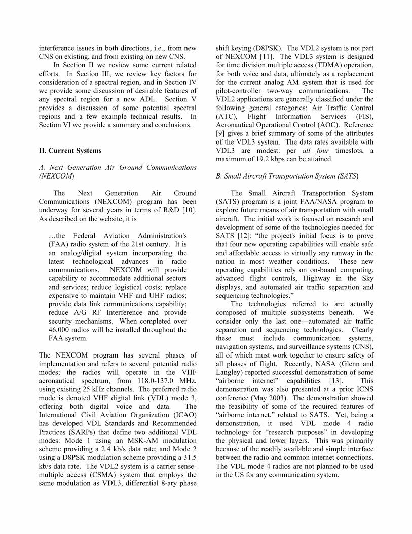
The second result, for the MLS band, is given in Figure 2. Here we show the MLS error probability in the presence of a DS-SS signal. As can be seen, for the DS-SS to MLS power ratio JSR~10 dB or more, and DS-SS chip rate Rc>20 MHz, MLS performance does not degrade significantly. Attainable DS-SS data rates in this case can be on the order of 1 Mbps. While the MLS error probability (or signal-to-noise-plus-
Figure 2. Performance of MLS in presence of DS-SS in overlay; MLS Pb vs. SNR (Eb/N0) for various
DS-SS bandwidths, relative power levels. interference ratio, from which error probability was derived) is not necessarily the best metric for determining the effect on the MLS navigation system, the result is a promising first-order one. VI. Summary & Conclusions In this paper we have provided selected results from a recent study we have completed [9]. In the study, we considered a number of potential spectral bands for use in a new aviation data link system, and reviewed a number of existing aeronautical systems. From our research, one obvious conclusion (not new!) is that existing aeronautical spectrum will be inadequate to satisfy currently-projected communications demand for the future, using existing systems. That is, there is a clear need for development of a new ADL system to provide SATS and/or other CNS services. Data rates for all existing and proposed systems are inadequate for most new services, e.g., weather imagery. Key issues regarding the choice of spectrum for new services include RF propagation conditions, actual availability of the spectrum for aeronautical use, and the wide availability of proven technology. For moderate data rates and good range, the ILS band could be
1
1
Pb
Rc=20 MHzJSR=10 dB
Rc=20 MHzJSR=15 dB
AWGN
Rc=60 MHzJSR=18 dB
Rc=200 MHzJSR=28 dB
0.1
0.01
10-3
10-4
10-5
10-6
Eb/N0 (dB)0 5 10 15 20
1
1
Pb
Rc=20 MHzJSR=10 dB
Rc=20 MHzJSR=15 dB
AWGN
Rc=60 MHzJSR=18 dB
Rc=200 MHzJSR=28 dB
0.1
0.01
10-3
10-4
10-5
10-6
Eb/N0 (dB)0 5 10 15 20
suitable for a new ADL system; for airport surface and terminal airspaces, the MLS band, with its capability for large data rates, is most attractive. Yet selection of appropriate spectrum is not based only on physical layer criteria—political considerations must also be addressed. Coordination of the use of multiple spectral bands for CNS applications, possibly for a macro diversity approach, is also recommended. References [1] FAA NAS website, http://www2.faa.gov/nasarchitecture/blueprnt/comm.htm, 27 June 2003. [2] G. Burke, “Shaping the National Airspace System for the 21st Century,” Proc. of 16th DASC, Irvine, CA, pp. 0.4-1—0.4-7, 26-30 October, 1997. [3] P. Smith, “IPSKY: IPv6 for the Aeronautical Telecommunications Network,” Proc. of 20th DASC, Daytona Beach, FL, pp. 7.A.6-1—7.A.6-11, 14-18 October, 2001. [4] K. Martzaklis, “NASA Datalink Communications Research & Technology Development For Aeronautics,” Proc. of Integrated CNS Workshop, Session E—Research and Technology Development for Far-Term Datalink Systems, Cleveland OH, 1-3 May 2001. [5] T. P. Kabaservice, “Technical and Economic Benefits of VHF Digital Link Mode 3 Integrated Voice and Data Link for Air Traffic Control Communications,” Proc. of Integrated CNS Workshop, Session B1—Datalink Comm. Systems, pp. 55-59, Annapolis, MD, 19-22 May 2003. [6] A. Jahn, M. Holzbock, J. Muller, R. Kebel, M. de Sanctis, A. Rogoyski, E. Trachtman, O. Franzrahe, M. Werner, F. Hu, “Evolution of Aeronautical Communications for Personal and Multimedia Services,” IEEE Comm. Magazine, vol. 41, no. 7, pp. 36-43, July 2003. [7] D. W. Matolak, “CDMA for Communications in the Aeronautical Environment,” Proc. 16th DASC, Irvine, CA, pp. 9.4-21—9.4-28, Oct. 1997. [8] E. Haas, M. Schnell, “Advanced Airport Data Link—Concept and Demonstrator Implementation for a Modern Airport Data Link,” Proc. of Integrated CNS Workshop, Session B1—Datalink Comm. Systems, pp. 83-92, Annapolis, MD, 19-22 May 2003. [9] D. W. Matolak “Alternate Communications Spectrum Study (ACSS) for Aviation Data Links
(ADL),” Project Final Report, NASA grant NAG3-2815, Ohio University and Avionics Engineering Center, October 2003. [10] Department of Transportation, Federal Aviation Administration, NEXCOM website, http://www1.faa.gov/nexcom, 11 July 2003. [11] Department of Transportation, FAA, System Requirements Document (SRD), Next-Generation Air/Ground Communications (NEXCOM), FAA-E-2598, V0.0, 10 January 2002. [12] Small Aircraft Transportation Systems website, NASA Langley Research Center, http://sats.larc.nasa.gov/, 7 July 2003. [13] “Development of Airborne Internet will Benefit General Aviation,” NASA Office of Aerospace Tech., http://www.aero-space.nasa. gov/curevent/news/vol4_iss3/cns.htm, 13 July 03. [14] MITRE Corp., Capstone Proposed Initial Draft Standard for UAT, 22 May 2000. [15] Radio Technical Commission Aeronautical, website, http://www.rtca.org, 11 July 2003. [16] Department of Transportation, Federal Aviation Admin., ADS-B Wk group website, http://adsb.tc.faa.gov/WG5.htm, 11 July 2003. [17] G. Stuber, Principles of Mobile Communication, 2nd ed., Kluwer Academic Publishing, Boston, MA, 2001. [18] Third Generation Partnership Project, website: http://www.3gpp.org, 11 July 2003. [19] Third Generation Partnership Project 2, website: http://www.3gpp2.org, 11 July 2003. [20] D. van Roosbroek, EUROCONTROL, personal communication, March 2003. [21] Defense Advanced Research Projects Agency, briefing attached to SOL Reference-Number-PRDA-02-01-IFKPA, November 2001. [22] L. B. Milstein, D. L. Schilling, R. L. Pickholtz, M. Kullback, E. G. Kanterakis, D. S. Fishman, W. H. Biederman, D. C. Salerno, “On the Feasibility of a CDMA Overlay for Personal Communications Networks,” IEEE Journ. Select. Areas Comm., vol. 10, pp. 655-668, May 1992. [23] D. W. Matolak, J. T. Neville, “Spectral Overlay of Direct-Sequence Spread Spectrum in the Instrument Landing System Glideslope Band for Airborne Internet,” Proc. of 22nd DASC, Indianapolis, IN, October 12-16, 2003. [24] D. W. Matolak, J. T. Neville, “Spectral Overlay of Direct-Sequence Spread Spectrum in the Microwave Landing System Band,” Proc. IEEE Aerospace Conf., Session 4.18, Big Sky, MT, March 6-13, 2004.

Frequency Spectrum for New Aviation Data Links: Initial Study
ResultsICNS
April 2004James R. Branstetter
FAA Office of Aviation Research (AAR-210)NASA Langley Research Center
Hampton, VA 23681phone: 757.864.6396
fax: 757.864.1908email: [email protected]
OHIO UNIVERSITYOHIO UNIVERSITYAvionics Engineering Center Avionics Engineering Center
School of Electrical Engineering & Computer ScienceSchool of Electrical Engineering & Computer Science
David W. Matolak, Ph.D.School of EECSOhio University
Athens, OH 45701phone: 740-593-1241
fax: 740-593-0007email: [email protected]
Ohio University 2
Outline• Overall Study Aim:
– Identify key factors involved in the use of alternate spectrum in various bands for a future integrated CNS data link
• Background• Overview of current related efforts• Key factors in spectrum selection• Desired new ADL system attributes• Example spectral regions• Summary

Ohio University 3
Spectrum Shortage or Not?THE END OF
SPECTRUMSCARCITY
NEW TECHNOLOGIES AND REGULATORY REFORM WILL BRING A BANDWIDTH BONANZABY GREGORY STAPLE & KEVIN WERBACH
IEEE Spectrum Magazine, March 2004, pp. 48-52
Ohio University 4
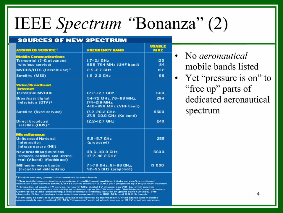
IEEE Spectrum “Bonanza” (2)
• No aeronauticalmobile bands listed
• Yet “pressure is on” to “free up” parts of dedicated aeronautical spectrum
Ohio University 5
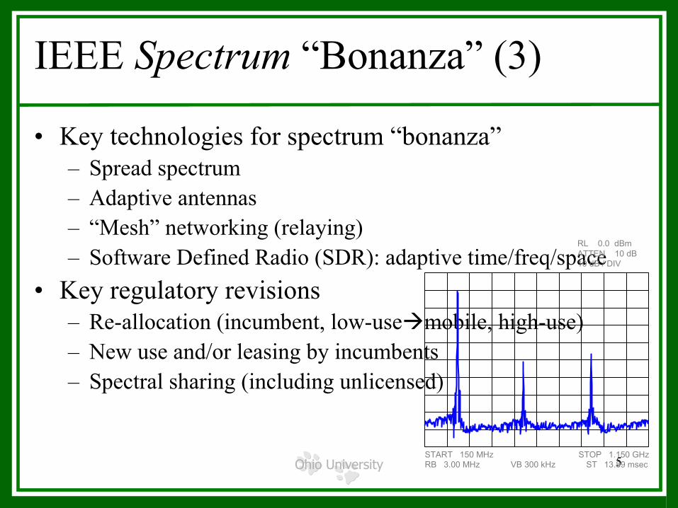
IEEE Spectrum “Bonanza” (3)
• Key technologies for spectrum “bonanza”– Spread spectrum– Adaptive antennas– “Mesh” networking (relaying)– Software Defined Radio (SDR): adaptive time/freq/space
• Key regulatory revisions– Re-allocation (incumbent, low-use mobile, high-use)– New use and/or leasing by incumbents– Spectral sharing (including unlicensed)
START 150 MHz STOP 1.150 GHzRB 3.00 MHz VB 300 kHz ST 13.89 msec
RL 0.0 dBmATTEN 10 dB10 dB / DIV

Ohio University 6
…and from DARPA, NSF
• DARPA’s Advanced Technology Office – neXt Generation (XG) Communications program– “All spectrum may be assigned, but
…most spectrum is unused!”– “XG is developing the technology and system concepts for
DoD to dynamically access all available spectrum”• NSF’s Computing & Communications Foundation
Division– Networking Technology & Systems (NeTS) program– “Explore dynamic spectrum management architectures and
techniques”
Ohio University 7
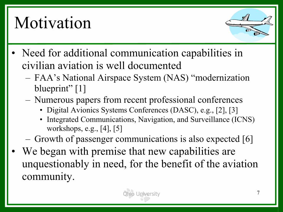
Motivation• Need for additional communication capabilities in
civilian aviation is well documented – FAA’s National Airspace System (NAS) “modernization
blueprint” [1]– Numerous papers from recent professional conferences
• Digital Avionics Systems Conferences (DASC), e.g., [2], [3]• Integrated Communications, Navigation, and Surveillance (ICNS)
workshops, e.g., [4], [5]– Growth of passenger communications is also expected [6]
• We began with premise that new capabilities are unquestionably in need, for the benefit of the aviation community.

Ohio University 8
Study Focus• Key factors in spectrum selection for aviation data links• Systems that can deliver VDL-or-higher data rates• Aeronautical spectra (C, N, or S)• Two or three lowest layers of the communications
protocol stack: – physical layer (PHY) – data link layer (DLL)– medium access control (MAC) layer

Ohio University 9
Potential Spectral Regions
• In principle, Vast amounts of unused spectrum, at frequencies above those in common use – e.g., V band ~ 45 GHz– Technologies are not presently available to economically
deploy communication systems in these bands • Propagation conditions favor use of lower frequencies
for aeronautical transmission ranges of interest– Tens of meters to a few hundred kilometers
• Restrict attention to frequency bands below Ku band (12 GHz), for A→G and G→A communication (higher f’s possible for satellites)

Ohio University 10
Potential Spectral Regions (2)
• For the lower frequency limit, we selected the upper limit of the HF band (lower limit of VHF band),approximately 30 MHz– To support multiple users with data rates ~ 100kbps or more
requires more bandwidth than available in HF band and ↓• Hence, we focus on VHF, UHF, and SHF bands• Also most likely that any new ADL system will be
deployed in spectrum already dedicated to aeronautical applications, either communications or otherwise.

Ohio University 11
Potential Spectral Regions (3)
MLS not deployed widely. Technologies for this band less mature, but very wide bandwidth available. Propagation conditions may dictate use of directive antennas, and/or use in shorter range conditions.
5-5.25 GHzMicrowave Landing System (MLS)
Existing transceivers very high power, making coexistence very challenging. Commercial use of military spectrum is likely a large administrative and political challenge.
225-328.6 MHz335.4-399.9 MHz
Military UHF
Developed in FAA Capstone (ADS-B) project. Only two channels currently; design modifications needed for increased data rates.Peer-peer user addressing not currently available.
Two 1 MHz channels:
971 MHz (CONUS), 981 MHz (Alaska)
Universal Access Transceiver (UAT)
Only ≅ 5 MHz spectrum, but good propagation conditions. Coexistence with tone-modulated ILS signal is biggest challenge.
329-335 MHzILS Glideslope
FAA choice for digital voice & data. Data rate limited. Maintaining only 25 kHz channel BW ⇒ only moderate data rate achievable.
118-137 MHzVDLM3
CommentsFrequency Band
System or Spectrum

Ohio University 12
Current Related Efforts: NEXCOM (1)
• NEXCOM is (quote)– “FAA’s radio system of the 21st century. … – An analog/digital system incorporating latest technological
advances in radio communications – Will provide capability to
• accommodate additional sectors and services• reduce logistical costs• replace expensive to maintain VHF and UHF radios• provide data link communications capability• reduce A/G RF Interference • provide security mechanisms.
– When completed over 46,000 radios will be installed throughout the FAA system.”

Ohio University 13
NEXCOM (2)• Operates in dedicated aero spectrum at VHF • Uses existing FDMA channel structure• Modes 1-3, plus analog 8.33 kHz AM• For mode 3 (TDMA)
– Maximum data rate is 19.2 kbps for ALL 4 time slots– Differential 8PSK modulation– 3 or 4 time slots– Time division duplexing– Point-to-point A→G and G→A, plus G→A broadcast

Ohio University 14
Current Related Efforts: SATS (1)• Small Aircraft Transportation System (SATS) (quote)
– “… project's initial focus to prove that four new operating capabilities will enable safe and affordable access to virtually any runway in the nation in most weather conditions.” [12]
• on-board computing, • advanced flight controls, • Highway in the Sky displays,• automated air traffic separation and sequencing technologies.”
– Last one relies on efficient and secure CNS
Ohio University 15
SATS (2)• Demo done (NASA Glenn) using VDL4• Next stage planned is transfer of demo system to
SATSLab and AIC for experimental evaluations and commercialization. – May require substantial changes to demo system in terms of
components, capabilities, and modes of operation. – Final SATS/AI (even lowest few layers) likely substantially
different from demo system, in terms of• frequency band of operation• available data rates and channel bandwidths• number of simultaneous users• range and spatial discrimination

Ohio University 16
Current Related Efforts: UAT (1)
• Universal Access Transceiver (UAT)– Mostly applied to surveillance applications, in particular
Automatic Dependent Surveillance—Broadcast (ADS-B).• Successfully deployed on a trial basis in Alaska. Plans for its use in
contiguous US, and standardization, underway– Fairly simple (⇒ robust) binary modulation, to reduce aircraft
radio costs– Like VDL3, uses time slotting, and burst transmissions
• Aircraft transmissions not assigned to slots--randomly accessed [14]– Current UAT transceivers canNOT provide individual
message addressing and true peer-to-peer connectivity
Ohio University 17
UAT (2)• Requires a dedicated 1 MHz channel• Time division duplexing• Maximum data rate 1004.167 kbps for ALL users
(Total) with no packet collisions and no overhead• Practical throughput ~ 0.36(0.82)1Mbps ≅ 295 kbps for
all users (Total); 820 kbps maximum if synchronized (coordinated among all users)
• Point-to-point A→G and G→A, plus G→A broadcast
Ohio University 18
Current Related Efforts: AIC (1)• Airborne Internet Consortium
– Recently formed group [9], also termed the Airborne Internet Collaboration Forum
– Members from aviation industry, government organizations, academia
• Group purpose– Encourage the development of open systems architecture and
standards for aviation digital communications– Foster and promote internet protocols in aviation– Develop intellectual content to guide and influence public and
private investment

Ohio University 19
AIC (2)• Group meetings have sought participation, discussed
group’s aims, and outlined items for a workplan• Nascent workplan items of direct relevance to our work:
– Integrated CNS requirements– Architectural candidates, trade-offs and evaluation– AI system design– Test and evaluation– AI design and use of VDL, SAT, 802.11…– Applicable technology assessment– Applicable communication standards assessments.

Ohio University 20
Key Factors in Spectrum Selection
• Propagation– Best-case, “free-space” path loss is 20log(4πdf/c) dB, so at a
given distance, path loss increases by 20 dB per decade in f• Example: d=10km, PL=92 dB at f=100MHz, PL=112 dB at f=1GHz
– Other attenuations (absorption, scattering, etc.) also generallyincrease with frequency
– Conclusion: For a given amount of transmit power, link range is maximized if carrier frequency is minimized

Ohio University 21
Key Factors in Spectrum Selection
• Technology– Desire hardware/software, systems, subsystems thatare “readily available,” or “nearly available”– Re-use of existing techniques, software, hardware is
economically attractive, and can optimize reliability– Examples:
• Wireless LAN technologies developed for use in the ISM bands (2.4 GHz, 5.8 GHz)
• Cellular technologies (800-900 MHz bands)

Ohio University 22
Key Factors in Spectrum Selection
• Spectrum “Availability”– CAN we (are we permitted to) use a given spectral region for
aeronautical applications?• Regulatory constraints• Existing users of the band, and existing systems
– New ADL most easily deployed in systems already designated (reserved) for aeronautical use

Ohio University 23
t
s(t)
A
-A
-3A
3A
t
s(t)
A
-A
-3A
3Az(t)
t
1
R
tR,1tR,2 tR,3
...
uR,1 uR,3uR,2
R-∆R
z(t)
t
1
R
tR,1tR,2 tR,3
...
uR,1 uR,3uR,2
R-∆R
0 50 100 150 200 250 300 350-1.5
-1
-0.5
0
0.5
1
1.5
Time (ms)
I & Q
I & Q Symbols in MSK
Key Factors in Spectrum Selection
• Waveforms– Which physical, medium access control, and data link layer
techniques are best suited?– For multiple access: FD? TD? CD?– For robustness, security, spread spectrum very attractive– Advanced processing can be used to enhance performance
• Adaptive or high-gain antennas (easiest at higher frequencies)• Forward error correction coding• Interference cancelling• Equalization/RAKE for dispersive (multipath) channels• Adaptive transmitter power control

Ohio University 24
Desired ADL Attributes
• For widespread acceptance, ADL system must offer capabilities not present or not fully supported by existing systems.
• Generally ⇒ New ADL system – Should offer higher Rb than existing systems– Should be able to serve large # users “simultaneously” in any
given geographic area– Geographic area (range for air-ground, ground-air, or air-air
communications) should be as large as possible– Connectivity should be ideally peer-to-peer

Ohio University 25
Desired ADL Attributes (2)• Allow wide variety of data rates & data traffic types,
with differing requirements on QoS (latency, integrity )– Variety of message rates would enable ADL system use for
multiple purposes, enhancing acceptance.• Last, system should be reliable ⇒ redundancy, and
should be secure in several ways– Difficult to spoof– Difficult to eavesdrop upon, for privacy reasons– Difficult to disrupt or overload
• Finally: standardization essential

Ohio University 26
Note on Spread Spectrum• Use of spread spectrum noted for security advantages• Spread spectrum also of interest for
– Robustness (to multipath, interference…)– Popularity
• All new cellular systems are spread spectrum• Wireless LANs are spread spectrum• All secure military systems use spread spectrum• EUROCONTROL experimenting with spread spectrum
2 1.5 1 0.5 0 0.5 1 1.5 260
50
40
30
20
10
00
60
20 log Ham ffa 1,( )( ).
20 log Hc1 ffv 1,( )( ). 17
10 log Hv ffv( )( ). 35
22 ffa50
ffv50, ffv
50,
narrowbandDS-SS
“despread”
frequency
PowerSpectralDensity
• This has focused some of our work on analysis & simulation of performance of SS

Ohio University 27
“Macro” Diversity• Use of different frequency bands simultaneously, to
improve performance, availability, and data rate– Adaptively utilize all time/frequency/spatial dimensions
• Two limited versions– Adaptive “band hopping”
• Select whatever band is available, as needed– Scheduled “band hopping”
• Example: use VHF band for long range, lower data rate messages during en-route transmissions, then SHF band for short-range, higher data rate messages in terminal/surface areas

Ohio University 28
Example Spectral Regions (1)
• ILS Glideslope band (~329-334 MHz)– Good propagation conditions– Moderate bandwidth– Coexistence with ILS needs further study
• Orthogonal allocations• DS-SS spectral overlay
– Mostly available technology at RF• VHF band (current 118-137 MHz)
– Good propagation conditions– Moderate-to-large bandwidth– Coexistence with AM, VDL big issue, i.e., supplant VDL?– Mostly available technology at RF
Ohio University 29
Example Spectral Regions (2)• “UAT band”
– Acceptable propagation conditions– Moderate bandwidth IF the channels can be obtained– Coexistence with UAT and JTIDS
• Orthogonal allocations– Mostly available technology at RF
• Military UHF– Similar to UAT
• Acceptable propagation conditions• Moderate bandwidth IF the channels can be obtained• Coexistence with existing systems• Mostly available technology at RF
– Biggest issue: civilian use of military spectrum

Ohio University 30
Example Spectral Regions (3)• MLS
– Short-range propagation conditions (unless high-G antennas)– VERY large bandwidths ⇒ high data rates, large # users– Coexistence with MLS signals
• Orthogonal allocations• DS-SS spectral overlay
– Mostly new (and lower transmit power) technology at RF– Added motivation: since spectrum being “coveted” by other
(non-aeronautical) entities, USE it or LOSE it!

Ohio University 31
Summary
• We considered a number of potential spectral bands for use in a new aviation data link system– Required that we also consider a number of existing
aeronautical systems• One obvious conclusion (not new!)
– Existing aeronautical spectrum inadequate to satisfy currently-projected communications demand for the future, using existing systems.
• Clear need for development of a new ADL system to provide SATS, Airborne Internet, and/or other CNS services
Ohio University 32
Summary (2)
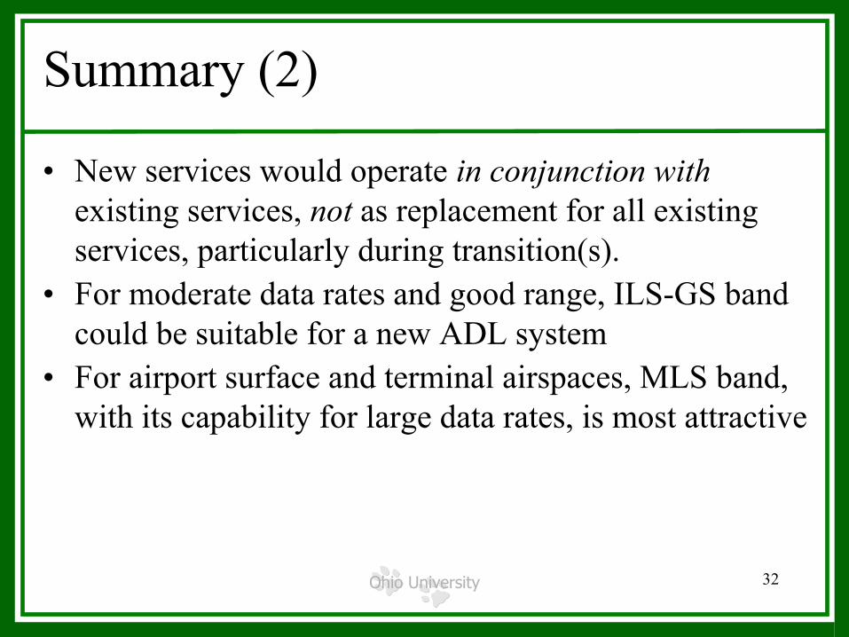
• New services would operate in conjunction withexisting services, not as replacement for all existing services, particularly during transition(s).
• For moderate data rates and good range, ILS-GS band could be suitable for a new ADL system
• For airport surface and terminal airspaces, MLS band, with its capability for large data rates, is most attractive

Ohio University 33
Future Work
• Extend analyses, simulations for ILS-GS and MLS– Better channel models, spatial variation, etc.
• Waveform and MA design for MLS– Prototyping and testing for surface/terminal communications
and to maintain aeronautical spectral rights• Cooperation with radio manufacturers, Airborne
Internet Collaboration Group, NASA, FAA, etc.• Determination of feasibility of using military UHF
spectrum• Multi-band analyses

Ohio University 34
Questions?

Ohio University 35
Backup Slides• General list of info used as inputs• Specific system info used as inputs• Some ILS-GS and MLS technical results
Tall mountain to climb…(Everest)
Ohio University 36
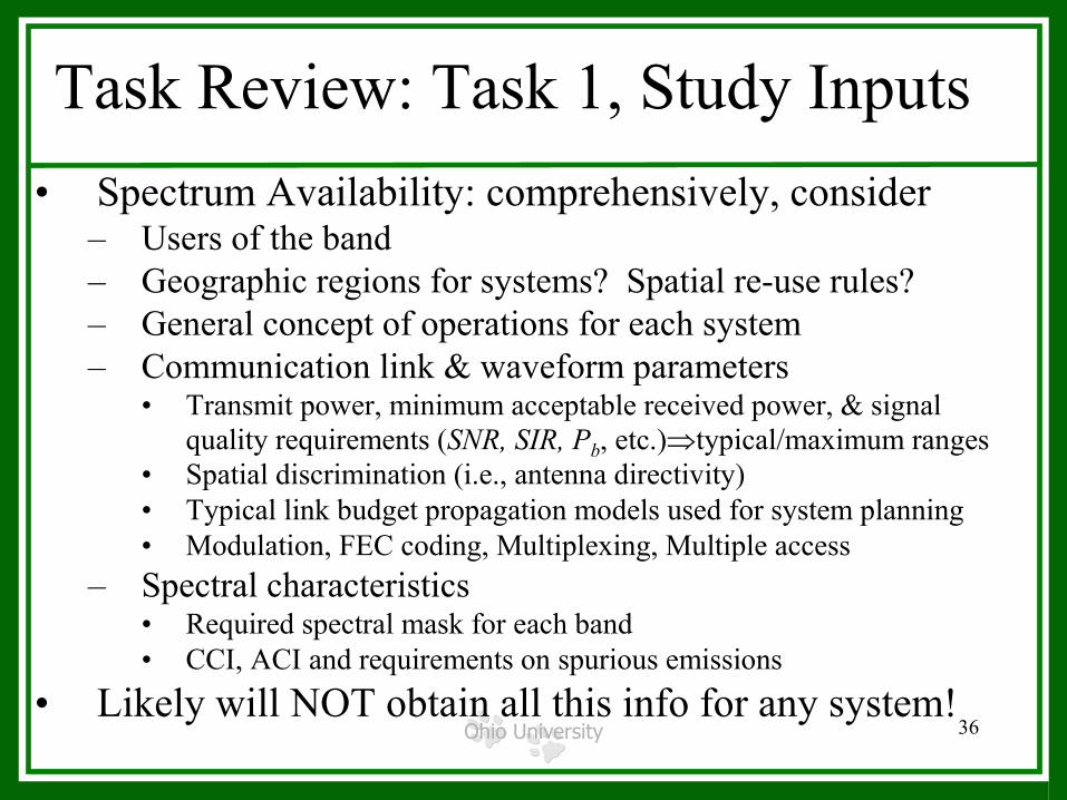
Task Review: Task 1, Study Inputs• Spectrum Availability: comprehensively, consider
– Users of the band– Geographic regions for systems? Spatial re-use rules?– General concept of operations for each system– Communication link & waveform parameters
• Transmit power, minimum acceptable received power, & signal quality requirements (SNR, SIR, Pb, etc.)⇒typical/maximum ranges
• Spatial discrimination (i.e., antenna directivity)• Typical link budget propagation models used for system planning• Modulation, FEC coding, Multiplexing, Multiple access
– Spectral characteristics• Required spectral mask for each band• CCI, ACI and requirements on spurious emissions
• Likely will NOT obtain all this info for any system!
Ohio University 37
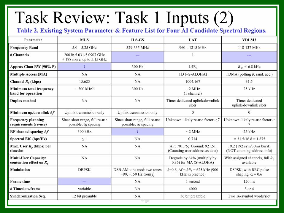
Task Review: Task 1 Inputs (2)Table 2. Existing System Parameter & Feature List for Four AI Candidate Spectral Regions.
Two 16-symbol words/slot36 bit preambleNA12 bit preambleSynchronization Seq.
3 or 44000NAvariable# Timeslots/frame
120 ms1 secondNA---Frame time
D8PSK, with RRC pulse shaping, α = 0.6
h=0.6, ∆f = hRb = 625 kHz (900 kHz in practice)
DSB AM tone mod: two tones ±90, ±150 Hz from fc
DBPSKModulation
With assigned channels, full Rbavailable
Degrade by 64% (multiply by 0.36) for MA (S-ALOHA)
NANAMulti-User Capacity: contention effect on Rb
19.2 (192 sym/30ms burst)(NOT counting address info)
Air: 701.75; Ground: 921.51(Counting user address as data)
NANAMax. User Rb (kbps) per timeslot
≅ 31.5/16.8 = 1.8750.714NA≤ 1Spectral Eff. (bps/Hz)
25 kHz~ 2 MHz?300 kHzRF channel spacing ∆f
Unknown: likely re-use factor ≥7
Unknown: likely re-use factor ≥ 7Since short range, full re-use possible; ∆f spacing
Since short range, full re-use possible; ∆f spacing
Frequency planning requirements (re-use)
00Uplink transmission onlyUplink transmission onlyMinimum up/downlink ∆f
Time: dedicated uplink/downlink slots
Time: dedicated uplink/downlink slots
NANADuplex method
25 kHz~ 2 MHz(1 channel)
300 Hz~ 300 kHz?Minimum total frequency band for operation
31.51004.167NA15.625Channel Rb (kbps)
TDMA (polling & rand. acc.)TD (~S-ALOHA)NANAMultiple Access (MA)
B90 ≅16.8 kHz1.4Rb300 Hz?Approx Chan BW (90% P)
---1---200 in 5.031-5.0907 GHz+ 198 more, up to 5.15 GHz
# Channels
118-137 MHz960 – 1215 MHz329-335 MHz5.0 – 5.25 GHzFrequency Band
VDLM3UATILS-GSMLS Parameter

Ohio University 38
Task 1 Results: ILS Glideslope Band• 2 coexistence options w/tone-modulated ILS GS signal
– Avoidance: utilize adjacent frequencies• Narrowband or Spread Spectrum (DS or FH)
– Spectral Overlay• Direct-Sequence Spread Spectrum (DS-SS)• Power balancing between signals• Protect DS-SS via ILS-GS signal cancellation—easy for sinusoids• Protect GS via nulling transmitted DS-SS signal at GS frequencies
• Disadvantages to use of ILS-GS are– Limited bandwidth– For SS in overlay mode
• Complexities (notch filters and/or interference cancellers) if ILS-GSsensitivity can not afford small degradation
– For SS in avoidance mode• Very good filtering

Ohio University 39
Task 1: Two SS “Modes”
• Depiction of power spectra in two modes– Overlay– Avoidance
• DS-SS (possibly multicarrier)• FH-SS
f
ILS-GStones
DS-SS or FH-SS“avoidance”
DS-SS “overlay”

Ohio University 40
Model for Analysis: ILS-GS DS-SS
150}90,{0, ,MHz 330))(2cos()(
)()(5
1
±±∈≅+=
=∑=
kc
kck
kkk
fftffts
tstg
π
α
))(()cos()(1
0
)()(, ∑ +−∑=
−
=+
kcT
N
j
ijkN
ikciiDS TjkNtpcdtAtx
cωBPSK DS-SS signal=
ILS-GS signal=g(t)
+
w(t)(AWGN)
CoherentDownconverter
+ LPF
s(t) r(t)∫
+⋅
Tk
kTdt
T)1(
)(1xc(t)
TimingCircuit Spreading Code
Sourceclock, Rc
y(t) kd̂
correlator
g(t)Coherent
PhaseReference
Ohio University 41
Effect of GS on DS-SS, Example 1
• DS-SS Pb vs. SNR, with JSR=PGS/PDS a parameter
• DS-SS Rc = 5 MHz• DS-SS Rb = 5 kbps• Equal center
frequencies
1
0 dB6 dB
10 dB
0
1
10-2
10-4
10-6
10-8
Pb
5 10 2015 25Eb/N0 (dB)
JSR=-∞ dB
15 dB

Ohio University 42
Effect of GS on DS-SS, Example 2
• DS-SS Pb vs. SNR, with JSR=PGS/PDS & tone phases variable parameters
• DS-SS Rc = 5 MHz• DS-SS Rb = 50 kbps• Equal center frequencies• JSR=10 dB unless
otherwise specified• Smaller allowable JSR as
DS-SS Rb increases0 5 10 2015 25
Eb/N0 (dB)
Pb
1
10-2
10-4
10-6
10-8 JSR=-∞ dB
0 dB, Φ=[0, 0]
Φ=[π, π/4]
Φ=[π, 0]
Φ=[0, 0]
Φ=[π/2, π/4]
Ohio University 43
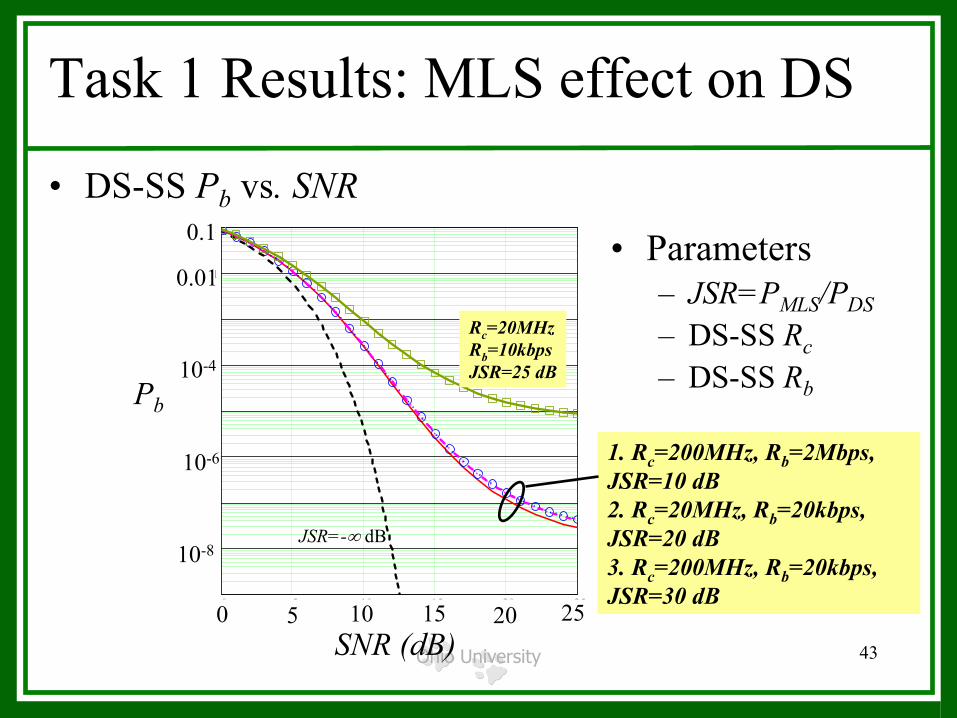
Task 1 Results: MLS effect on DS
• DS-SS Pb vs. SNR
0 5 10 15 20 251 .10 9
1 .10 8
1 .10 7
1 .10 6
1 .10 5
1 .10 4
1 .10 3
0.01
0.10.089
10 9−
PbDS Eb 10, 2108⋅, 2106⋅,( )PbDS Eb 30, 2108⋅, 2104⋅,( )
PbDS Eb 49−, 2108⋅, 2104⋅,( )
PbDS Eb 20, 2107⋅, 2104⋅,( )
PbDS Eb 25, 2107⋅, 1104⋅,( )
250 Eb
Pb10-4
10-8
0.01
0.1
10-6
SNR (dB)0 5 10 15 20 25
JSR=-∞ dB
Rc=20MHzRb=10kbpsJSR=25 dB
• Parameters– JSR=PMLS/PDS– DS-SS Rc– DS-SS Rb
1. Rc=200MHz, Rb=2Mbps, JSR=10 dB2. Rc=20MHz, Rb=20kbps, JSR=20 dB3. Rc=200MHz, Rb=20kbps, JSR=30 dB