freedom x remote panel pn: 808-0817 user guide
TRANSCRIPT
http://www.xantrex.comPN: 808-0817Freedom X Remote Panel
User Guide
HAZARD OF FIRE, ELECTRIC SHOCK, EXPLOSION, OR ARC FLASHThis Freedom X Remote Panel User Guide is in addition to, and incorporates by reference, the relevant product manuals for each product in the Freedom X series. Before reviewing this guide you must read the relevant product manuals. Unless specified, information on safety, specifications, installation, and operation is as shown in the primary documentation received with the product. Ensure you are familiar with that information before proceeding.Failure to follow these instructions will result in death or serious injury.
1 2
3
Exclusion for DocumentationUNLESS SPECIFICALLY AGREED TO IN WRITING, SELLER (A) MAKES NO WARRANTY AS TO THE ACCURACY, SUFFICIENCY OR SUITABILITY OF ANY TECHNICAL OR OTHER INFORMATION PROVIDED IN ITS MANUALS OR OTHER DOCUMENTATION; (B) ASSUMES NO RESPONSIBILITY OR LIABILITY FOR LOSSES, DAMAGES, COSTS OR EXPENSES, WHETHER SPECIAL, DIRECT, INDIRECT, CONSEQUENTIAL OR INCIDENTAL, WHICH MIGHT ARISE OUT OF THE USE OF SUCH INFORMATION. THE USE OF ANY SUCH INFORMATION WILL BE ENTIRELY AT THE USER’S RISK; AND (C) REMINDS YOU THAT IF THIS MANUAL IS IN ANY LANGUAGE OTHER THAN ENGLISH, ALTHOUGH STEPS HAVE BEEN TAKEN TO MAINTAIN THE ACCURACY OF THE TRANSLATION, THE ACCURACY CANNOT BE GUARANTEED. APPROVED CONTENT IS CONTAINED WITH THE ENGLISH LANGUAGE VERSION WHICH IS POSTED AT HTTP://WWW.XANTREX.COM.
Thank you for purchasing the Freedom X Remote Panel. This user guide will help you install and use the remote panel to operate and configure the Freedom X and XC series remotely.
Introduction
Check that you have the following items in the box before proceeding.- the Freedom X remote panel unit- user guide and mounting template
What’s In The Box
Acquire the following 6-conductor cable kit from Xantrex. Go to http://www.xantrex.com/power-products-support to order.• 25-ft. 6-conductor com cable kit (PN: 31-6257-00)• 50-ft. 6-conductor com cable kit (PN: 31-6262-00)
What’s Required
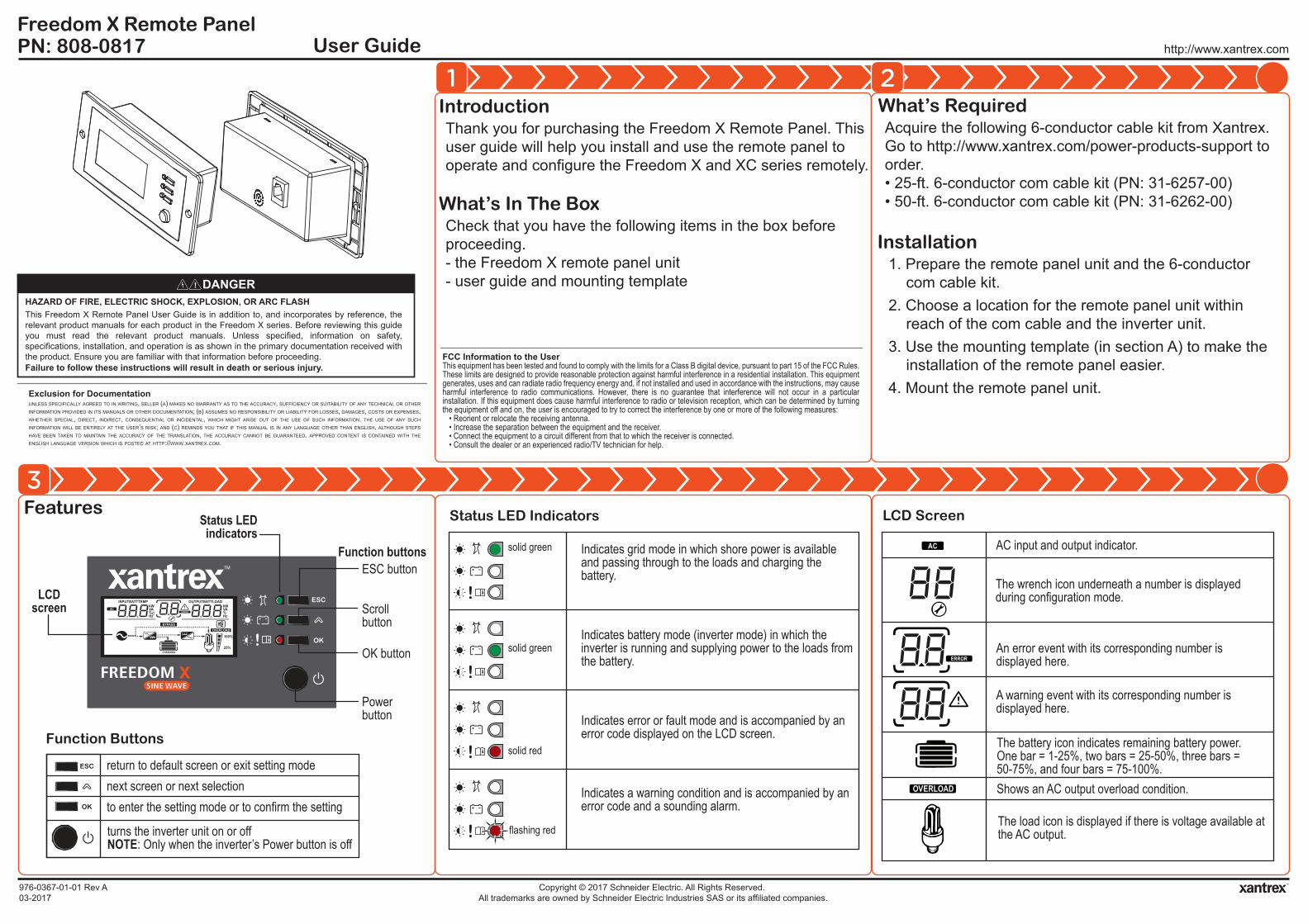
Features
Function Buttons
Status LED Indicators LCD Screen
1. Prepare the remote panel unit and the 6-conductor com cable kit.
2. Choose a location for the remote panel unit within reach of the com cable and the inverter unit.
3. Use the mounting template (in section A) to make the installation of the remote panel easier.
4. Mount the remote panel unit.
Installation
976-0367-01-01 Rev A03-2017
Copyright © 2017 Schneider Electric. All Rights Reserved. All trademarks are owned by Schneider Electric Industries SAS or its affiliated companies.
LCDscreen OUTPUTBATTLOAD
kW
100%
25%
HzVA%
kW
HzVA%C
INPUTBATTTEMP
AC
BYPASS
ERROR
OVERLOAD
CHARGING
Status LED indicators
Power button
ESC button
Scroll button
OK button
return to default screen or exit setting modenext screen or next selectionto enter the setting mode or to confirm the setting
turns the inverter unit on or offNOTE: Only when the inverter’s Power button is off
Function buttons Indicates grid mode in which shore power is available and passing through to the loads and charging the battery.
Indicates battery mode (inverter mode) in which the inverter is running and supplying power to the loads from the battery.
Indicates error or fault mode and is accompanied by an error code displayed on the LCD screen.
Indicates a warning condition and is accompanied by an error code and a sounding alarm.
solid green
solid green
solid red
flashing red
AC
ERROR
OVERLOAD
AC input and output indicator.
The wrench icon underneath a number is displayed during configuration mode.
An error event with its corresponding number is displayed here.
A warning event with its corresponding number is displayed here.
The battery icon indicates remaining battery power. One bar = 1-25%, two bars = 25-50%, three bars = 50-75%, and four bars = 75-100%.Shows an AC output overload condition.
The load icon is displayed if there is voltage available at the AC output.
FCC Information to the UserThis equipment has been tested and found to comply with the limits for a Class B digital device, pursuant to part 15 of the FCC Rules. These limits are designed to provide reasonable protection against harmful interference in a residential installation. This equipment generates, uses and can radiate radio frequency energy and, if not installed and used in accordance with the instructions, may cause harmful interference to radio communications. However, there is no guarantee that interference will not occur in a particular installation. If this equipment does cause harmful interference to radio or television reception, which can be determined by turning the equipment off and on, the user is encouraged to try to correct the interference by one or more of the following measures:
• Reorient or relocate the receiving antenna.• Increase the separation between the equipment and the receiver.• Connect the equipment to a circuit different from that to which the receiver is connected.• Consult the dealer or an experienced radio/TV technician for help.
C
M
Y
CM
MY
CY
CMY
K

Viewing Information During Battery Mode
Contact Informationhttp://www.xantrex.comPlease contact your Xantrex Sales Representative or visit the Xantrex website at:http://www.xantrex.com/power-products-support/
http://www.xantrex.comPN: 808-0817Freedom X Remote Panel
User Guide
4
5 6
976-0367-01-01 Rev A03-2017
Copyright © 2017 Schneider Electric. All Rights Reserved. All trademarks are owned by Schneider Electric Industries SAS or its affiliated companies.
The bar represents load consumption levels. 100% is an indication of full capacity and 25% indicates low consumption. All the bars disappear at < 20 watts, and AC load indicates zero watt power.
Shows up in grid mode when AC shore power is present. If the power is being qualified, then this icon will flash.
Shows that the unit is in grid mode and is bypassing shore power directly to the loads.
This icon shows when there is power conversion from AC to DC - charging. Applicable only to Freedom XC units.
This icon shows when there is power conversion from DC to AC - inverting.
The alarm buzzer is muted. For more information, see Freedom inverter’s Owner’s Guide.
100%
25%
BYPASS
Press scroll [ ] to move to the next screen. Press [ ] to return to the home screen .1
Viewing Information During Grid Mode Adjusting Feature SettingsPress scroll [ ] to move to the next screen. Press [ ] to return to the home screen .1
INPUTBATTTEMP
VA OUTPUTBATTLOAD
kW
100%
25%
INPUTBATTTEMP
VA OUTPUTBATTLOAD
100%
25%
AC V
OUTPUTBATTLOAD
Hz
AC INPUTBATTTEMP
V OUTPUTBATTLOAD
Hz100%
25%
BATTTEMP
OUTPUTBATT
100%
25%
1
5
2 3
4
BATTTEMP
OUTPUTBATT
100%
25%
1
1
battery voltage = 12.5V, AC load = 1.2kW output voltage = 120V, output frequency= 60Hz
Inverter firmware version = U1 1.01 Remote panel firmware version = U2 1.10
input voltage = 120V, input frequency = 60Hz
1
1. Press and hold the [ ] button for three seconds to enter the feature settings mode.
2. Press the scroll [ ] button to move through the differentfeature settings.
3. Press the [ ] button to select a setting number and change its value.
4. Press the scroll [ ] button to change the value until you reach the desired value.
5. Press the [ ] button to confirm the change.6. Repeat previous steps to set other feature settings.7. Press [ ] to exit the feature
settings mode.
NOTE: See the Freedom X / XC Owner’s Guide for information on the individual settings.
NOTE: It may take a minute for the settings to take effect on the inverter unit.
3NOTE: Screen appears only when AC qualification is pending.
2NOTE: Screen appears only in Freedom XC units.Greyed out icons also appear only in Freedom XC units.
100%
25%
BYPASS
BATT
V 100%
25%
BYPASS
INPUT
ALOAD
AAC
100%
25%
BYPASS
INPUT
VLOAD
HzAC
100%
25%
BYPASS
100%
25%
BYPASS
2 3
5
1
4
1
1
1
battery voltage = 12.5V, charging = no charging input current = 15.6A, load current = 6.8A
Inverter firmware version = U1 1.01 Remote panel firmware version = U2 1.10
input voltage = 120V, input frequency = 60HzCHARGING CHARGING
CHARGING CHARGING
CHARGING
C
M
Y
CM
MY
CY
CMY
K

http://www.xantrex.comPN: 808-0817Freedom X Remote Panel
Mounting Template
A
976-0367-01-01 Rev A03-2017
Copyright © 2017 Schneider Electric. All Rights Reserved. All trademarks are owned by Schneider Electric Industries SAS or its affiliated companies.
Installing the Remote Panel Unit on the Wall1. Place the template on the wall.
2. Mark the corners (or trace the dotted lines) of the recess outline on the wall.
3. Mark the two mounting holes for the two screws on the wall.
4. Remove the template from the wall.
5. Cut along the recess outline on the wall to make a hole for the remote panel’s body.
6. Pre-drill the mounting holes appropriate to the mounting screws (not provided) that will be used.
7. Mount the remote panel unit on the wall.
NOTE: Ensure the inside wall is free of obstructions, such as pipes, insulation, and electrical wiring.Ensure the recess depth is more than 50 mm.
allow enough space for
connecting the com cable plug
recess outline
mountinghole
mountinghole
126.0 mm
107.0 mm
51.0 mm
38.0 mm
C
M
Y
CM
MY
CY
CMY
K