free & easy construction tips - ® diy guides about : woodworking
TRANSCRIPT
FFRREEEE && EEAASSYY CONSTRUCTION TIPS
FOR ALL OF OUR DO-IT-YOURSELF
SHED PLANS
HHOOWW TTOO BBUUIILLDD SSHHEEDDSS
CCOONNSSTTRRUUCCTTIIOONN GGUUIIDDEE CONTENTS
INTRODUCTION START UP EXCAVATION FOUNDATION WALL FRAMING ROOF FRAMING ROOFING WINDOWS & DOORS SIDING ILLUSTRATIONS CONCLUSION
2 2 3 4 8 9 10 11 11 12 22
DDiissccoovveerr wwhhaatt yyoouu ccaann bbuuiilldd..
Over 80 plans to choose from
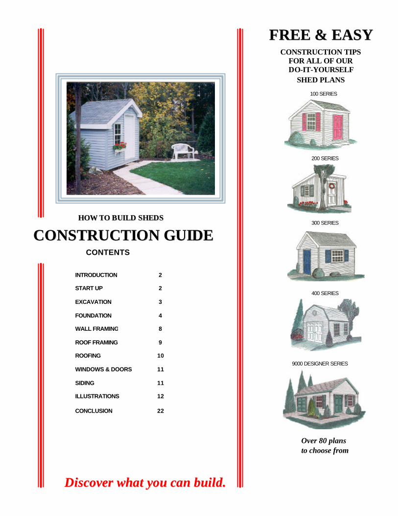
100 SERIES
200 SERIES
300 SERIES
400 SERIES
9000 DESIGNER SERIES
2
IINNTTRROODDUUCCTTIIOONN Here we freely provide, for the do-it-yourself shed builder, additional helpful construction tips on building sheds. This guide is designed specifically for people who are using our shed plans, and want more information. It will also interest anyone else who is interested in such a building project. The printable version of our “Construction Guide” in PDF format is free to everyone. It requires Adobe Acrobat Reader, which is also available free at our web site.
Customers who have more questions are invited to email our customer service.
Because we have so very many plans it should be noted that unless stated otherwise plan # 312 is the plan used throughout this guide so as not to confuse the reader. It is the “300 SERIES” shed illustrated with a blue door shown on the guide’s cover. It is illustrated as built on a concrete pad instead of on a wooden floor. The door is in the front wall which is 8’– 0” wide from left to right (plus the thickness of the siding). It is 10’- 0” deep from front to back (plus the thickness of the siding). All of these dimensions exclude the thickness of siding because there are many styles of siding that you can choose from and it has no bearing on the construction of your shed at the framing stage. Some product names used in this guide may be unfamiliar to you in your area. This is because of different trade names used by different area manufacturers. Your building supplier will know of similar and equal products. Although all of our sheds are different structurally and in appearance all the needed information that is unique to them is in the plans. This guide can be used for all of the shed plans sold by Just Sheds Inc.
TTHHEE SSTTAARRTT--UUPP 1 Once you have your plans and know where you want to place your new shed you should
contact your local public utilities. They will inform you about any pipes or cables that are buried in the ground in the area. This is usually free of charge. You should also avoid disrupting septic systems.
2 Know where your property lines are then contact your local building department and inquire about the required distance needed for side and rear yard setbacks if any and about any building permits that you may require.
3 Our different shed plans offer three types of foundations that are suited to small or large size sheds. The easiest type to build is where the floor joists are nailed to a skid foundation, which rests on a small gravel bed. . The second type is built on a concrete pad (slab on grade) onto which the walls and the roof are built. This type of construction is well suited for large sheds where heavy loads may be placed on the floors The third type is better suited to sloping yards or soils that subject to movement, it is the concrete pier style that supports an elevated wooden floor with the walls and roof placed on top.
3
EEXXCCAAVVAATTIIOONN
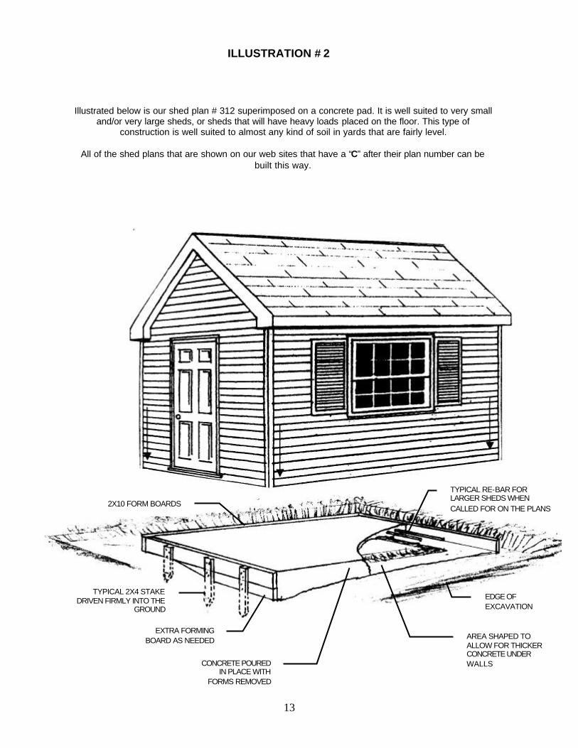
4 Once you have chosen a location for your shed and you chose to build your shed on a skid foundation remove the topsoil in the area down to the depth mentioned in your plans. In the case of plan #312 the area will be just one and half wide by ten feet long for each of the two skids. If you have chosen to build your shed on a concrete pad, dig out an area that is at least 6” bigger than the shed is all the way around. This allows for working space and formwork. Dig it out in a shape that allows the concrete pad to be thicker under the walls and reinforced when specifically called for in the plans. If you want, some of this excavated material can be replaced with any granular material that is compactable and inexpensive to buy. This should be done before you build the formwork as described in item #15.There may be materials in you area that need no compaction at all. The amount needed will of course depend on your excavation and on the elevation you want for your shed floor. Also remember that the finer the materials are the easier they are to shovel and handle. When your excavation is finished it should look like the areas and items in illustration # 2.
5 If you choose to build your shed on concrete piers you should find or build a good benchmark. Benchmarks are just reference points (see illustration # 3 and 4) used to find and establish the elevations of the different parts of your shed. For example, it is necessary that the 4 foundation footings have the same elevation when the concrete is poured in them. On top of these are placed the concrete blocks etc. and then the wooden floor joists. The end result of this should be a level floor. It is your benchmark that will help and guide you in this task. It can be almost anything; a specific point or mark on a building or sidewalk, as long as it stays put and is clearly marked so that you always use the same point. You can even use the top of a 2”X 4” wooden stake hammered very firmly into the ground. A 2X4 stake was the chosen benchmark for this shed building project. See illustration # 3 and 4.
6 After completing the work described in item # 5 you should mark the 4 outside corners of the shed with small stakes. Make sure that the corners are at 90° angles. Measuring the distance from front left to the right back corners and comparing this with the distance between the remaining corners will confirm 90° angles when the distance is the same. Make the necessary adjustments so that the two are exactly the same and the area still is 8’ X 10’ or whatever the size of your new shed is going to be.
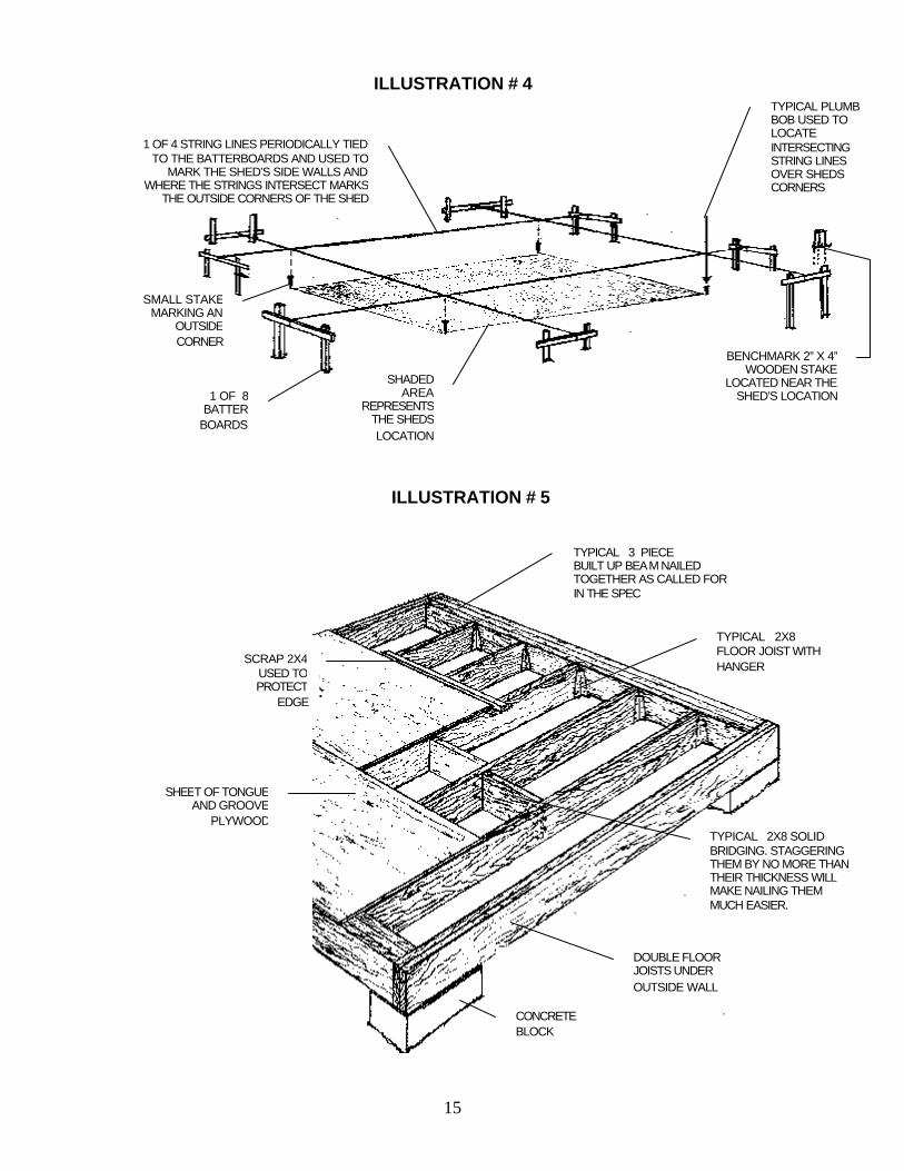
7 Erect the 8 batter boards and put up the string lines as shown in illustration # 4. They can be built out of any sturdy lumber strong enough so that they stay put if bumped into and support the tightly tied string lines tied onto them. They should be installed about 3ft. from the shed’s location. A few feet more if you need to dig deeper than 3 feet. As these strings are only strung when needed it is a good idea to make a small saw cut in the top board marking the right location for it when next needed. The batter boards are removed once the foundation is complete and ready for the wood framing. Batter boards are not used if you choose to build your shed on a skid foundation or a concrete pad.
4
8 If you have chosen to build your shed on piers, dig the four holes so that they can accommodate the foundation footings as called for in your plans. You can reinstall the string lines on the batter boards anytime you wish to check on your progress. The footings do not need to be in the exact place as the concrete blocks can be somewhat off center on the footings as long as the blocks are plumb (straight up and down) and at exactly 90° angles to the other concrete block piers.
FFOOUUNNDDAATTIIOONNSS
9 Use a carpenter’s level and a straight edge (a long and very straight 2X4 will do nicely) to help you establish a uniform elevation for the footings from the benchmark that is shown in illustration # 3. If bad soil conditions or the slope of your site do not allow you to build it this way you can step down the footings in multiples of 8”. The technique for doing this is shown in illustration # 3. It is best to use multiples of 8” because that is the height of each standard concrete block with its mortar and so you just use blocks in different amounts according to your needs. If you plan to complete the foundation by pouring a concrete pier, which is another option, then the elevation at the bottom can be different but the tops of the piers must always be at the same elevation. This is important because all of the roof rafters described in exact size, cut and angles in the “ RAFTER CUTING LAYOUT ” page of our plans have actually been cut and proven to fit. In order for the rafters to fit properly as planned and described, it is important that the corners of your shed have 90° angles and the floor be level. Level within ¼ of an inch from the lowest point on the floor to highest is good.
10 This “level” standard is actually not that difficult to achieve, because you can use your benchmark to check on and make adjustments as you progress. Once you have completed your excavation, hammer a small grade stake in each of the four holes. Put them in an area near the outside of the footing as described in illustration # 3, pier B. This small grade stake is needed if you decide to pour the concrete right into the four holes without building concrete forms. Just pour to the top of the stake and level off with a trowel or just use a block of wood. It does not need to be smooth. It is easier to build this way but the holes must have a size similar to the required footings as stated on the plans. If you need or are going to build with concrete footing forms because of soil or other conditions then you can use the forms as an elevation guide instead of the four grade stakes. Examine the poured concrete for levelness when it has cured. Further minor adjustments needed can be made with the thickness of the mortar, but do not make a mortar line thicker than ½”.
11 Build one pier first and then measure over to the other ones and build them one at a time. You can make minor adjustments as you go. Making and keeping the corners square (90° angles) is also important and not really hard to do. You should confirm this as you go, by using the methods described in item # 6 the two cross-distances mentioned should be within ¼” of each other
12 The top of the benchmark shown in illustrations # 3 and 4 always represent the chosen finished floor level (the elevation you want your floor to be at) the bottom of your
5
straight edge is also at this same level plane and so you just measure down to get at the needed elevations in the different piers in multiple increments of 8”. The straight edge must of course always be level as shown. In illustration # 3 pier C shows a small concrete footing in a shallow excavation with 2 blocks on top, which meets the needs here, all hypothetically of course. Pier D shows the footing’s concrete was poured in a wooden form and it has 3 blocks on top. The tops of piers C and D are at the same level but the bottom of D is 8” lower for whatever reason. Pier B hypothetically had its concrete for the footing poured right into the excavation that was dug. A grade stake was used here instead of forms to establish at what level the concrete should be. On top was placed 6 blocks; the bottom of this pier is much lower than the others because of a hypothetical back yard slope. The 6 blocks times 8” each equals 48”. This leaves 8” left from 56” that is stated in the illustration. The 8” left represent the space needed for the wooden floor which for this particular shed plan calls for 2” X 8” floor joists, which is actually closer to 7 3/8” high plus 5/8” for the plywood equals 8”. You can see from all this that making the needed calculations establishing the different elevations is actually quite easy to do. It certainly is much easier than digging the piers needlessly deeper, it gets you a better shed and it saves you money.
13 Once you have the 4 holes dug out and/or formed with wooden forms and stakes you can pour in the needed concrete. The type of concrete mix bought in a bag requiring only water to be mixed with it is a good product for this job. After it has hardened as described in item 19, you can proceed with the work described in item 20.
14 Building on a skid foundation or a concrete pad is different in that among other things there are no batter boards used. You make it level and square as you build. For a skid foundation lay the skids on the required level gravel. Nail all the joists in place and then just move one skid back or forth a bit so that it is square as described in item # 6 Install the plywood as describe in item # 24 to keep it square.
15 For the concrete pad version, after you have completed the excavation as described in item 4 proceed to build the concrete form with 2” X 10” lumber that is preferably as long as each side of the shed. Actually it is preferable that 2 of the 4 boards should be 3” longer so that you can nail them together for strength. It should be remembered that concrete is very heavy (about 4000 lbs per cubic yard) and your forms must not bend or bow out because some of the finished concrete can be seen. At this stage you are basically building a box in the sheds desired location. Lay it out so that it is near to being square (a few inches within being square) as described in item 6. Nail the 4 boards firmly together so that you have a form that will make an 8’X 10’ concrete pad. Find the highest point in your excavation using a carpenter’s level on the top edge of the so-called box and start building and securing your concrete forms here. At the highest point of the box, nearing the highest end of that board, drive the first stake firmly into the ground and then secure it to the board. Install the second stake near the lowest point of that board; while remembering you should have a stake every 3 feet. You may notice at this time there may be a small space under the form. A space of ¾” is ok in that concrete should not be so watery that it escapes through it. Larger spaces can be blocked with an extra forming board as described in illustration # 2. Proceed in this same manner on the next part of the form after you have made it completely square as described in item 6. Digging under the
6
forms a bit and then hammering the stakes down further can make minor adjustments in level. The top of the form and the concrete poured in to the top of the form should meet the level standards set in item 9. Once the formwork is complete you can install the concrete’s steel reinforcing if and when it is called for in the plans and specifications. Steel re-bar should be about 2” below the surface and can be held there by placing it on top of pieces of concrete or something like old bricks or you can buy what the industry calls chairs, which are designed for this purpose, but you may have to buy a hole case full. Wire mesh is often simply laid in the form and then with a rake it is pulled up to the mid point of the concrete as it is being poured into place.
16 Once the concrete is poured in place you should install the anchor bolts as called for in the plans and specifications. Do not wait until the concrete starts to set. They are installed 2” in from the concrete’s edge and should be placed in an area not near wall studs. Check your plans. Once the concrete firms up it is trowelled smooth. You may have to do this a few times to get the desired results. If this is your first experience with pouring and finishing concrete do not leave the site. Concrete can set surprisingly fast and you only get one chance to finish it. When this is done it’s best to protect it from rain and direct sun with a tarp if you have.
17 After the concrete has hardened which can vary from 1 to 2 days or even up to 7 (it depends mostly on warmth and dryness) you can lay the concrete blocks or start the wood framing depending on the building method chosen.
18 You should only use the kind of blocks that have square edges and flat smooth sides and ends as shown in all our plans. The standard style of stretcher blocks does not look suitable and frost can hold and lift them thereby changing the elevations you worked hard to obtain. The type of mortar mix you just add water to is a great product for this job but it should be mixed very well because the more you mix it the better it sticks to your trowel which is very handy for people who are new to this. Last but not least you should install the saddle anchors, making sure that they are installed in the right direction and alignment.
19 When all the mortar and concrete is dry you can remove the batter boards, concrete forms and benchmark. Backfilling around the concrete block piers should be done with care and equally on each side so as not to push it out of plump. The concrete pad on the other hand will in all likelihood never move.
FFLLOOOORR FFRRAAMMIINNGG
20 Our entire portfolio of shed plans use only standard “Platform” framing techniques and materials. This is the most common method of building homes in North America and is rapidly being copied in other parts of the world. It’s also the best way to build sheds because it has the advantage of cost saving, adaptability and strength. It is also an easier way to build, especially when compared to older methods of building with wood in the
7
past, such as balloon framing or post-and-beam construction. Post-and-beam construction is the method seen in old pictures of barn raising where a dozen or so men are seen working in the roof rafters. Clearly not an easy task.
21 This guide will go into more details as we go but for now you can see from the following
brief descriptions that platform framing is much easier. Unless you are building on a concrete pad (in which case it is your platform) you would first install the skids or main beams as the case may be and then floor joists and plywood. This, once completed gives you a nice working platform on which you build the next parts (hence the name platform framing), which are the walls. All the walls are built laying down flat on the platform and then they are put aside (if you still need the platform to build more walls) or they are put upright and installed in place (all of which depends on which walls you chose to build and install first). Once all the walls are built and installed the next floor would be built in the same way just described. If it does not have a second floor you would build the roof. For many of our larger sheds you would start by installing the ceiling joist first. Onto this you temporarily put the roofing plywood and this then becomes your next platform from which you would install the roof rafters. All of this work must of course be done with the highest regard for safety. If you are new to laying out or drawing onto wood to show where the different pieces of wood are nailed together have a look at illustration # 10.
22 The materials list for the wooden flooring part of this actual shed calls for 3 pieces of 2”X 8”X 16’ which are then cut in two for each of the two 3-piece built up beams shown in illustrations # 5. All the lumber specified in our materials list is always based on it being delivered to you and in sizes commonly stocked. You may however if available choose to buy shorter sizes and pick it up yourself. While the novice builder may logically only want straight lumber, it is, in fact, more important to select which pieces you use first, where you use them and in which way. This is because lumber does not stay straight nor does it stay crooked, it changes with its moisture content. Wood when it is cut and kiln dried in a lumber mill is usually straight because it has the same moisture content. The most common way to deal with crooked lumber is to always put the crown or bow up. No matter what you are building the bow is always up. The weight on the floor or roof will push it down somewhat. Just imagine what you would have if they went down or even worse some up and some down. The bow is always up and the bowed members should be beside each other not one here and there. Lumber that is badly bowed is simply cut into shorter or smaller pieces where it is not noticed.
23 Start the actual floor framing as shown in illustration # 5 by selecting the straightest 2X8 then install it as the first innermost piece of the 3 piece built up beams that will support your shed. Nail it to the saddle anchor. Then install the double joist under the outside walls. Notice they do not have joist hangers but rest on top of the concrete block and are nailed into the end of the 3 piece built up beam. Use the straightest joist you have for this part. Next come the middle joist hangers and joists as called for on your actual plans. Care must be used when calculating, measuring and cutting all framing members so that when put together they fit well. Next install the two remaining pieces of the built up beams and nail them together as called for on the specifications that came with your plans. The double floor joists under the outside walls must also be nailed together like the beams but it is easier to nail them together when this part of the framing is rigid enough to take heavy hammer blows. Many experienced carpenters will use 3 ¼” spiral nails for
8
this but drive them in at a bit of an angle so they do not come out the other side and become a safety hazard. These nails can be used to nail all the framing members and so you need buy only one size and one size fits all. Next install the bridging as described in illustration # 5 if and when they are called for on your plans.
24 Once the structural flooring members are in place you can install the tongue and groove plywood starting at the edge of the framing. Please note that a 4X8 sheet of tongue and groove plywood actually only covers an area that is 47 ½” wide. So if by way of example your shed needs 3 sheets to cover 12’ you would be short 1 ½”. In this case you would start the plywood in ¾” and leave a ¾” space at the other end. This saves time and money and works well as long as all the sheet’s edges are supported and that’s the nice part about tongue and groove. The tongue of one sheet is supported by the groove of the other. To get the tongue and groove to fit together can be tricky when either one is damaged or all the joists are not installed with all of the crowns up. Start by checking for damage. Any damaged sheet found is used first or last so that it does not have to fit into another. Once the first is nailed in place the next one is placed on the joists, aligned, and hammered into place using a scrap piece of 2X4 so as not to damage the next sheets edges. After you complete the nailing according to specifications you are ready to start building walls.
WWAALLLL FFRRAAMMIINNGG
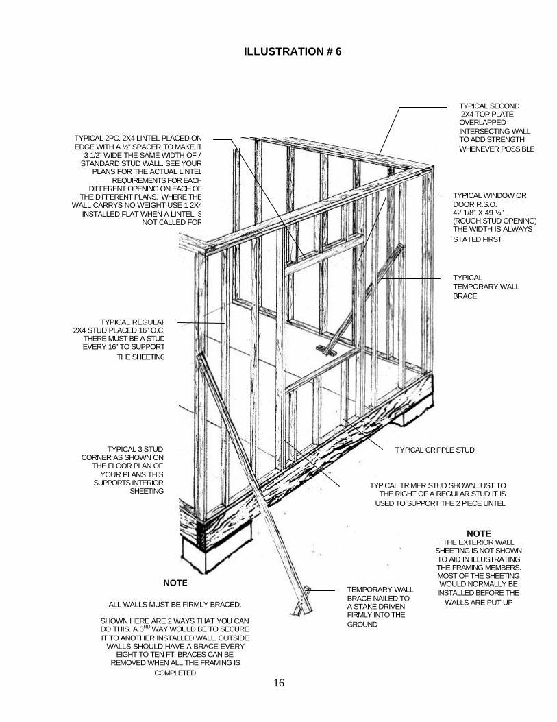
25 Walls as mentioned are easier to build when laying on a flat surface and then put upright and into place. Look at illustration # 6 so that you are familiar with some of the terms used to describe the different members used in wall construction. Even if you know them by a different name or can’t remember them, that’s ok because illustration # 6 will give you a very good idea what it’s all about. Start the wall construction by choosing 2 straight sill plates. One for the bottom and 1 for the top. Place them beside each other and mark them showing where the different studs go. The needed studs, their location and spacing are shown on the “ FLOOR PLAN ” page that comes with all our plans. Again if you are new to laying out or drawing on wood to show where the different pieces of wood are nailed together have a look at illustration # 10.
26 Place the wall studs for the corners first. Choose ones that are straight. Then come the
other ones. Remember to always put the crown up. Then place the trimmer studs. Nail them to the sill plate. Next install the lintels, sills and cripple studs and nail as per plans and specifications. The actual size of lintels will vary greatly with each different plan, which depends on their needs and the roof loads they must carry. Some may just have a sill instead of an actual lintel because they carry little or no load at all. Once all the framing members are nailed together, make the frame square and install the wall sheeting onto the framing members. Your plans will show wall sheeting installed over the 3 piece built up beam and the header and double floor joist. This gives the sheeting the continuity that makes the siding look better. The sheeting for this area comes from the scrap pieces
9
cut out from the window and door openings. In other words the bottom of the sheet you nail on the wall framing does not extend all the way down. This is because it makes the walls too hard to handle and can produce more waste. Nailing the sheets on after the wall is up is also harder to do and this does not make the walls rigid. Rigidity in the walls will help you keep them up straight and square. You should have some sheeting on each wall. Again care must be used when calculating, measuring and cutting all framing members so that when put together they fit well. Most carpenters draw the actual walls out onto the plywood or concrete. This helps them visualize and measure exactly. The walls then cover these chalk or pencil lines. Take your time and do it well because this can be the most rewarding part of the project. Things start to happen fast at this stage including the pride that comes with seeing things come together. It gives you a nice feeling. When you have built a wall just move it off your platform and make the next wall until they’re all made. Then they are put in place-installed plumb (straight up and down within 1/8” difference between the top and bottom of the wall) and then braced as shown in illustration # 6.
27 Walls that are longer than 12’ are often built in two. This will depend on the amount of
helpers you have. In this case the two parts are then spliced together with the second top plate that is shown in illustration # 6. Walls installed on concrete slabs first have the needed anchor bolt holes drilled into the bottom sill plate and temporarily put in place so that you are sure that they will fit when they are used to build the wall and then it’s installed as described in item #28. The second top plate where possible always overlaps the intersecting walls for strength as shown in illustration # 6. Where this is not possible such as in our free plans just use a single top plate and extra nails. This method can also be used for the back 1/3 of our saltbox style sheds. All the roofs on our saltbox designs have one slope longer by exactly 1/3 of the total length or width. Or in other words if the side or irregular shaped wall of your shed is 120” long (10-0”) then the front part 80” will have 2 top plates and be the same height as the front walls. The back part (40” or 1/3) will have just one plate and it will slope down to the same height as the back or lowest wall. Our plans are drawn to have all of the long or main roof rafters resting on double top plates. This is done for strength and allows you to nail the rafters anywhere as long as they are always installed at 16” on center.
28 Take care when installing the walls so that they are plumb, well nailed according to the specifications that come with our plans and are braced as shown in illustration # 6. This is important because buildings at this stage of construction are vulnerable to wind.
RROOOOFF FFRRAAMMIINNGG
31. At Just Sheds Inc. we know that roof framing is the most difficult part of construction,
whether it is a simple roof as shown in our free plans or more complex. This is why we give all the needed details in our “RAFTER CUTTING LAYOUT” page in our plans and the ‘ACTUAL SIZE RAFTER CUTTING TEMPLATES. They all show the sizes and angles you need to cut. All of them have actually been cut and proven to fit. It is helpful when reading this guide to refer to your plans. If you have yet to select or purchase a set, print out the free shed plans so you can refer to it for more clarification on some of the
10
items referred to in the framing part of this guide. Looking at the plans for the shed you want to build is helpful especially as you read about the roof framing part in this guide.
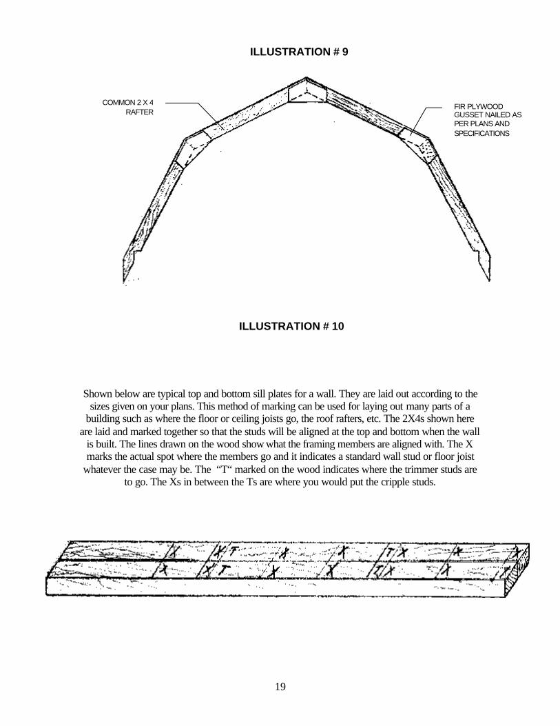
32. Once the walls are in place install the ceiling joists when your style of shed allows. Some barn styles and others do not have them. The 100 series need the rafters in place first because the one end of the ceiling joist is nailed to a rafter. In the 200 series the roof rafters are also the ceiling joists and if your shed has a barn style roof you should refer to item # 33 and illustration # 9. After the walls, come the rafters. Cut 2 as shown on your plans and temporarily put them in place with a spacer block (the same thickness as the ridge pole) to confirm they fit. Use them as a template to cut the others and proceed to install them with the ridgepole as shown in illustration # 7. Once the ridge pole is up you can install the rest of the rafters one at a time and alternately first on one side then on the other so as not to push the ridge pole crooked which can happen if you nail them all on one side first. Nail them all according to the specifications that came with your plans. The ridgepole can be a little longer and then trimmed to fit. Take care that the rafters are installed at right angle to the ridgepole or the roof sheeting will be difficult to fit.
33. The barn style roofs are framed by building a one-piece roof truss as shown in illustration # 9. This is best done on a flat surface such as the floor of your shed. Once built they are put aside and then installed one by one. Brace them with an angle brace in the same way the rafters are braced in illustration # 7. Once the truss types of rafters are in place install the 2X4 blocking at the hip and at the peek of the roof as per plans.
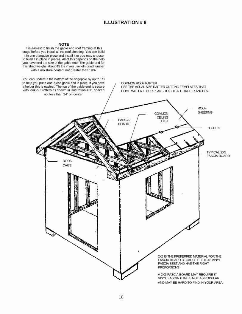
34. When all the rafters or trusses are in place install the fascia board onto the lower ends of the rafters as shown in illustration # 8. They can be a little longer and then trimmed to fit after. It is often easier to do it this way. Next install the front and back fascia boards at the ends of the ridgepole (or install a few short perpendicular lookout rafters as shown in illustration # 11 if it does not have a ridgepole) and onto the just installed horizontal fascia board. Next install the roof sheeting. It’s started at the bottom of the roof rafters as shown in illustration #8. Install the “H” clips as called for. They are used to support the sheet’s edges just like the tongue and grove plywood mentioned in item # 24. The last part is the bird’s cage, which is just a block of wood having the needed corresponding angles. It is the bird’s cage onto which vinyl soffit and fascia are secured.
RROOOOFFIINNGG
35. Although you can use almost any kind of roofing material on your new shed we recommend asphalt shingles in our plans because they are the most popular, durable, inexpensive and easy to install. Follow all of the manufacturer’s instructions that come with your new shingles. Installing the soffit and attic venting as called for in our plans is very important as it helps to keep the daytime temperature of the shingles down. Shingles that are routinely subjected to cool nights and then very hot days have a shorter lifespan. The vents called for in the plans can be on any side of the roof as long as it is near the top of it.
36. The best way to cut shingles is to use a hook blade which fits into a common utility knife. Stanley makes both and they are readily available and inexpensive to buy. Just hook the blade on the edge of the shingle and pull the knife firmly towards you. This cuts much
11
better than the often-recommended shears or tin sips which is like cutting sand paper with a pair of good scissors.
WWIINNDDOOWWSS && DDOOOORRSS
37. Installing the windows and doors in the sheds that we have designed is easy because there are no difficult components to make. The units recommended in our materials list are chosen for their appearance, quality and ease of installation. You can, of course, use any make of windows and doors that you like. They’re all easy to install just follow the manufacturer’s installation. Installing them can be a lot of fun because it’s easy to do and it sort of completes your project in that now you have your own secure little building. A neat little building that you have built.
SSIIDDIINNGG 38. Installing the siding is another fun part of your shed building project. We recommend
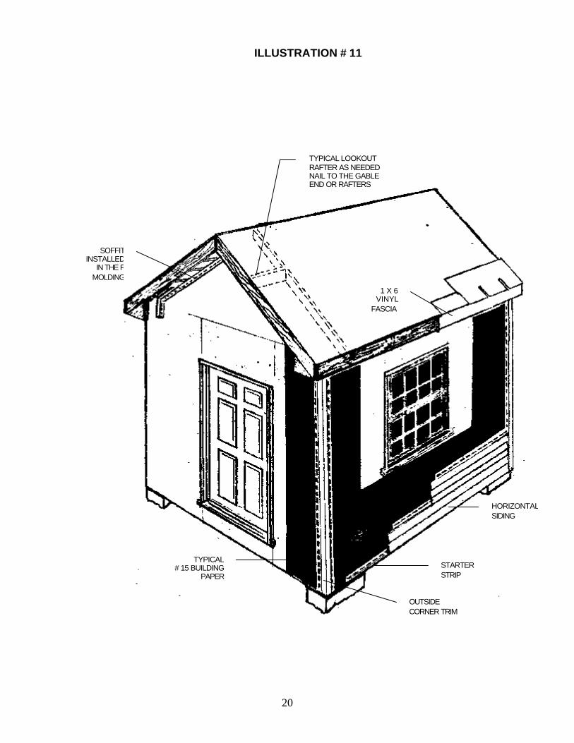
vinyl as the best material to cover your shed with because it’s maintenance free, comes in a host of colors and patterns that you can choose from and it’s inexpensive to buy. Vinyl siding is also a proven product. It’s easy to install and keeps it’s good looks for a long time. Although you should follow the instructions that come with the siding, illustration # 11 shows some of the items common to all such siding. Horizontal rather than vertical siding was chosen for this illustration.
39. First install vertically a full width piece ( 36” ) of # 15 asphalt paper on each of the corners. Just use a few of the roofing nails here and there to hold the paper in place. Later on the siding and trim when finished will hold it in place. The same roofing nails are used for the siding and trim. Next install the outside corners over the vertical piece of asphalt paper. Next install a strip of # 15 asphalt paper horizontally under the window as shown in illustration # 11. Care must be taken to give the paper a big overlap so that the wind will not drive rainwater in behind it. Horizontal laps should be 4” and vertical laps should be about 15” For better results vertical laps can be sealed with tar or another sealant that you may already have.
40. Next install the starter strip onto the bottom of the wall into which the first piece of siding slides up, and locks into. The siding is then nailed and then comes the next piece, etc. Install all trim and moldings over the building paper, except for soffit fascia. Trim must be installed around the windows and doors before you get to it with the siding. Install the “F” molding on the siding to receive the soffit material. Next comes the soffit which slides into the “F’ molding. Then install the under sill trim just under the roof shingles and slide the fascia up into it.
For those who were wondering, the “ F “ molding gets its name from its actual shape.
ILLUSTRATION # 1
12
.
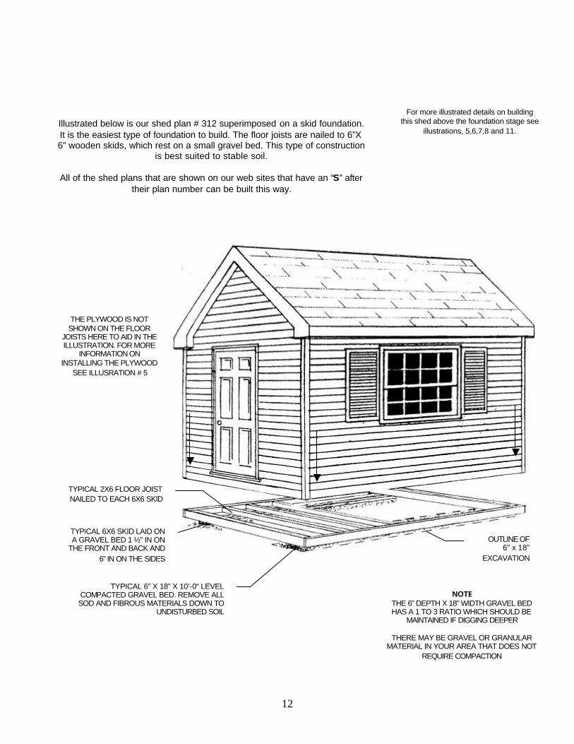
Illustrated below is our shed plan # 312 superimposed on a skid foundation. It is the easiest type of foundation to build. The floor joists are nailed to 6”X 6” wooden skids, which rest on a small gravel bed. This type of construction
is best suited to stable soil.
All of the shed plans that are shown on our web sites that have an “S” after their plan number can be built this way.
TYPICAL 6X6 SKID LAID ON A GRAVEL BED 1 ½” IN ON
THE FRONT AND BACK AND 6” IN ON THE SIDES
TYPICAL 2X6 FLOOR JOIST NAILED TO EACH 6X6 SKID
For more illustrated details on building this shed above the foundation stage see
illustrations, 5,6,7,8 and 11.
TYPICAL 6” X 18” X 10’-0“ LEVEL COMPACTED GRAVEL BED. REMOVE ALL SOD AND FIBROUS MATERIALS DOWN TO
UNDISTURBED SOIL
OUTLINE OF 6” x 18”
EXCAVATION
NOTE THE 6” DEPTH X 18” WIDTH GRAVEL BED HAS A 1 TO 3 RATIO WHICH SHOULD BE
MAINTAINED IF DIGGING DEEPER
THERE MAY BE GRAVEL OR GRANULAR MATERIAL IN YOUR AREA THAT DOES NOT
REQUIRE COMPACTION
THE PLYWOOD IS NOT SHOWN ON THE FLOOR
JOISTS HERE TO AID IN THE ILLUSTRATION. FOR MORE
INFORMATION ON INSTALLING THE PLYWOOD
SEE ILLUSRATION # 5
13
ILLUSTRATION # 2
Illustrated below is our shed plan # 312 superimposed on a concrete pad. It is well suited to very small and/or very large sheds, or sheds that will have heavy loads placed on the floor. This type of
construction is well suited to almost any kind of soil in yards that are fairly level.
All of the shed plans that are shown on our web sites that have a “C” after their plan number can be built this way.
2X10 FORM BOARDS
EXTRA FORMING BOARD AS NEEDED
TYPICAL 2X4 STAKE DRIVEN FIRMLY INTO THE
GROUND
AREA SHAPED TO ALLOW FOR THICKER CONCRETE UNDER WALLS
EDGE OF EXCAVATION
CONCRETE POURED IN PLACE WITH
FORMS REMOVED
TYPICAL RE-BAR FOR LARGER SHEDS WHEN CALLED FOR ON THE PLANS
14
ILLUSTRATION # 3
Illustrated below is our shed plan # 312 superimposed on concrete piers. It is well suited to smaller and medium size sheds, or sheds that will not have very heavy loads placed on the floors. This type of
construction is well suited to any kind of soil that is not stable and in yards that are not level.
All of the shed plans that are shown on our web sites that have a “P” after their plan number can be built this way.
PIER C PIER A
TYPICAL 2X4 BENCH MARK
56 ”
32 ”PIER D
PIER B
STRAIGHT EDGE WITH LEVEL ON TOP
3X3 SADDLE ANCHOR
GRADE STAKE
15
ILLUSTRATION # 5
TYPICAL 3 PIECE BUILT UP BEAM NAILED TOGETHER AS CALLED FOR IN THE SPEC
SMALL STAKEMARKING AN
OUTSIDE CORNER
1 OF 8 BATTER BOARDS
1 OF 4 STRING LINES PERIODICALLY TIED TO THE BATTERBOARDS AND USED TO
MARK THE SHED’S SIDE WALLS AND WHERE THE STRINGS INTERSECT MARKS
THE OUTSIDE CORNERS OF THE SHED
BENCHMARK 2” X 4” WOODEN STAKE
LOCATED NEAR THE SHED’S LOCATION
SHADED AREA
REPRESENTS THE SHEDS LOCATION
ILLUSTRATION # 4
SCRAP 2X4USED TO PROTECT
EDGE
SHEET OF TONGUE AND GROOVE
PLYWOOD
TYPICAL 2X8 FLOOR JOIST WITH HANGER
TYPICAL 2X8 SOLID BRIDGING. STAGGERING THEM BY NO MORE THAN THEIR THICKNESS WILL MAKE NAILING THEM MUCH EASIER.
DOUBLE FLOOR JOISTS UNDER OUTSIDE WALL
CONCRETE BLOCK
TYPICAL PLUMB BOB USED TO LOCATE INTERSECTING STRING LINES OVER SHEDS CORNERS
16
ILLUSTRATION # 6
TYPICAL 2PC. 2X4 LINTEL PLACED ON EDGE WITH A ½” SPACER TO MAKE IT
3 1/2” WIDE THE SAME WIDTH OF A STANDARD STUD WALL. SEE YOUR
PLANS FOR THE ACTUAL LINTEL REQUIREMENTS FOR EACH
DIFFERENT OPENING ON EACH OF THE DIFFERENT PLANS. WHERE THE
WALL CARRYS NO WEIGHT USE 1 2X4 INSTALLED FLAT WHEN A LINTEL IS
NOT CALLED FOR
TYPICAL WINDOW OR DOOR R.S.O. 42 1/8” X 49 ¼” (ROUGH STUD OPENING) THE WIDTH IS ALWAYS STATED FIRST
TYPICAL SECOND 2X4 TOP PLATE OVERLAPPED INTERSECTING WALL TO ADD STRENGTH WHENEVER POSSIBLE
NOTE THE EXTERIOR WALL
SHEETING IS NOT SHOWN TO AID IN ILLUSTRATING THE FRAMING MEMBERS. MOST OF THE SHEETING WOULD NORMALLY BE INSTALLED BEFORE THE
WALLS ARE PUT UP
TYPICAL TEMPORARY WALL BRACE
TYPICAL 3 STUD CORNER AS SHOWN ON
THE FLOOR PLAN OF YOUR PLANS THIS
SUPPORTS INTERIOR SHEETING
TYPICAL REGULAR2X4 STUD PLACED 16” O.C.
THERE MUST BE A STUD EVERY 16” TO SUPPORT
THE SHEETING
TEMPORARY WALL BRACE NAILED TO A STAKE DRIVEN FIRMLY INTO THE GROUND
NOTE
ALL WALLS MUST BE FIRMLY BRACED.
SHOWN HERE ARE 2 WAYS THAT YOU CAN DO THIS. A 3RD WAY WOULD BE TO SECURE IT TO ANOTHER INSTALLED WALL. OUTSIDE
WALLS SHOULD HAVE A BRACE EVERY EIGHT TO TEN FT. BRACES CAN BE
REMOVED WHEN ALL THE FRAMING IS COMPLETED
TYPICAL CRIPPLE STUD
TYPICAL TRIMER STUD SHOWN JUST TO THE RIGHT OF A REGULAR STUD IT IS
USED TO SUPPORT THE 2 PIECE LINTEL
17
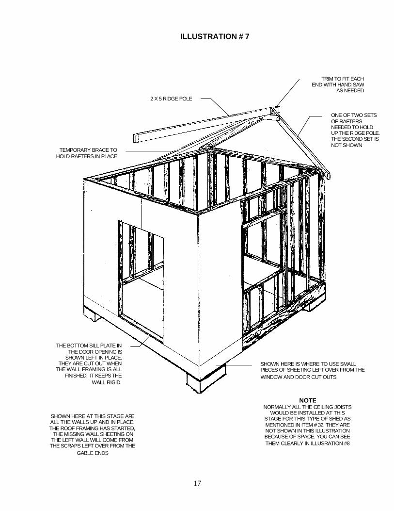
ILLUSTRATION # 7
ONE OF TWO SETS OF RAFTERS NEEDED TO HOLD UP THE RIDGE POLE. THE SECOND SET IS NOT SHOWN
SHOWN HERE AT THIS STAGE ARE ALL THE WALLS UP AND IN PLACE. THE ROOF FRAMING HAS STARTED, THE MISSING WALL SHEETING ON THE LEFT WALL WILL COME FROM THE SCRAPS LEFT OVER FROM THE
GABLE ENDS
NOTE NORMALLY ALL THE CEILING JOISTS
WOULD BE INSTALLED AT THIS STAGE FOR THIS TYPE OF SHED AS MENTIONED IN ITEM # 32. THEY ARE NOT SHOWN IN THIS ILLUSTRATION BECAUSE OF SPACE. YOU CAN SEE THEM CLEARLY IN ILLUSRATION #8
THE BOTTOM SILL PLATE IN THE DOOR OPENING IS
SHOWN LEFT IN PLACE. THEY ARE CUT OUT WHEN
THE WALL FRAMING IS ALL FINISHED. IT KEEPS THE
WALL RIGID.
TRIM TO FIT EACH END WITH HAND SAW
AS NEEDED
TEMPORARY BRACE TO HOLD RAFTERS IN PLACE
2 X 5 RIDGE POLE
SHOWN HERE IS WHERE TO USE SMALL PIECES OF SHEETING LEFT OVER FROM THE WINDOW AND DOOR CUT OUTS.
18
ILLUSTRATION # 8
NOTE It is easiest to finish the gable end roof framing at this
stage before you install all the roof sheeting. You can build it in one triangular piece and install it or you may choose
to build it in place in pieces. All of this depends on the help you have and the size of the gable end. The gable end for this shed weighs about 45 lbs if you use kiln dried lumber
with a moisture content not greater than 19%.
You can undercut the bottom of the ridgepole by up to 1/3 to help you put a one-piece gable end in place. If you have a helper this is easiest. The top of the gable end is secure with look-out rafters as shown in illustration # 11 spaced
not less than 24” on center.
COMMON ROOF RAFTER USE THE ACUAL SIZE RAFTER CUTTING TEMPLATES THAT COME WITH ALL OUR PLANS TO CUT ALL RAFTER ANGLES
FASCIA BOARD
ROOF SHEETING COMMON
CEILING JOIST
TYPICAL 2X5 FASCIA BOARD
BIRDS CAGE
2X5 IS THE PREFERRED MATERIAL FOR THE FASCIA BOARD BECAUSE IT FITS 6” VINYL FASCIA BEST AND HAS THE RIGHT PROPORTIONS A 2X6 FASCIA BOARD MAY REQUIRE 8” VINYL FASCIA THAT IS NOT AS POPULAR AND MAY BE HARD TO FIND IN YOUR AREA.
H CLIPS
19
Shown below are typical top and bottom sill plates for a wall. They are laid out according to the sizes given on your plans. This method of marking can be used for laying out many parts of a
building such as where the floor or ceiling joists go, the roof rafters, etc. The 2X4s shown here are laid and marked together so that the studs will be aligned at the top and bottom when the wall
is built. The lines drawn on the wood show what the framing members are aligned with. The X marks the actual spot where the members go and it indicates a standard wall stud or floor joist
whatever the case may be. The “T“ marked on the wood indicates where the trimmer studs are to go. The Xs in between the Ts are where you would put the cripple studs.
FIR PLYWOOD GUSSET NAILED AS PER PLANS AND SPECIFICATIONS
ILLUSTRATION # 10
ILLUSTRATION # 9
COMMON 2 X 4RAFTER
20
ILLUSTRATION # 11
TYPICAL LOOKOUT RAFTER AS NEEDED NAIL TO THE GABLE END OR RAFTERS
SOFFIT INSTALLED
IN THE F MOLDING
1 X 6VINYL
FASCIA
TYPICAL # 15 BUILDING
PAPER
OUTSIDE CORNER TRIM
STARTER STRIP
HORIZONTAL SIDING