frank deicke, fraunhofer ipms fraunhofer wolf-joachim ... · fraunhofer dlk / frank deicke...
TRANSCRIPT
Frau
nh
ofe
r
DLK / Frank Deicke
Computer-Aided Design of Antennas, Transmission Channels and the Optimisation
of Transponder Systems
Frank Deicke, Fraunhofer IPMS
Hagen Grätz, Fraunhofer IPMS
Wolf-Joachim Fischer, Dresden University of Technology
RFID SysTech 2008 (10.-11.06.2008)

Frau
nh
ofe
r
DLK / Frank Deicke
10.06.2008
2
Outline
Introduction
Transponder System Design and Objectives
Modelling and System Calculation
Optimisation Strategies
Example
Conclusion
Frau
nh
ofe
r
DLK / Frank Deicke
10.06.2008
3
Introduction
Differentiation on RFID systems
Communication & applicationsApplication → ID, object info, data logger, sensor systems
Type → active, passive
Antenna configuration
Environment
Link distance
Used protocol, compatibility (ISO, EPC, IEEE)
Frau
nh
ofe
r
DLK / Frank Deicke
10.06.2008
4
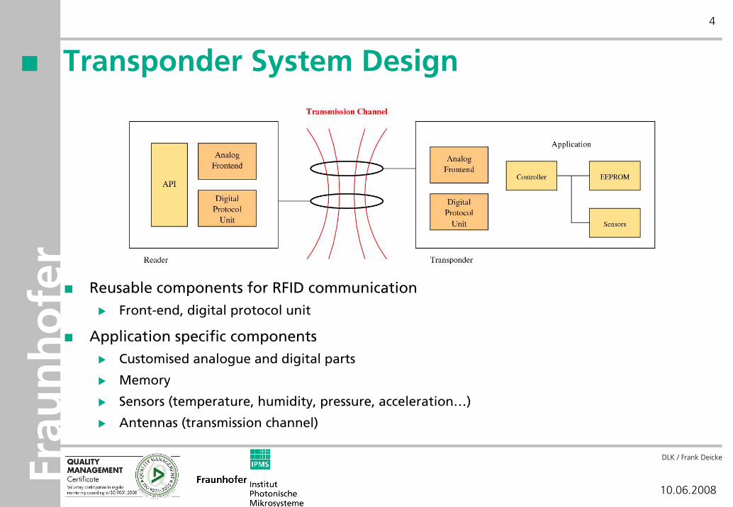
Transponder System Design
Reusable components for RFID communicationFront-end, digital protocol unit
Application specific componentsCustomised analogue and digital parts
Memory
Sensors (temperature, humidity, pressure, acceleration…)
Antennas (transmission channel)

Frau
nh
ofe
r
DLK / Frank Deicke
10.06.2008
5
Transponder System Design (2)
API
Logic Layer
Physical Layer
API
Logic Layer
Physical Layer
Transmission Channel
Tag App.Reader App.
Focus on systems with inductive coupling (LF and HF → 125 kHz, 13,56 MHz)
Data
Energy/Clock

Frau
nh
ofe
r
DLK / Frank Deicke
10.06.2008
6
Objectives – Summary
General Objectives
Bidirectional data transfer
Unidirectional energy transfer
Optimised antennas for reader and transponder
Objective Functions
Energy range
Transponder signal range
Approach of modelling and optimisation
Reducing prototyping
Frau
nh
ofe
r
DLK / Frank Deicke
10.06.2008
7
Constraints – Summary
Transmission Channel
Geometric dimensions of the antennas (min, max)
Surrounding
Link distance (constant or maximal)
System
Transponder voltage (min, max)
Demodulator sensitivity (Reader)
Data rate/band width
Frau
nh
ofe
r
DLK / Frank Deicke
10.06.2008
8
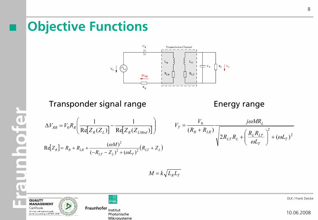
Objective Functions
Energy rangeTransponder signal range
22
0
)(2)(
TT
LTLLLT
L
LRRT
LLRRRR
MRjRR
VV
ωω
ω
+⎟⎟⎠
⎞⎜⎜⎝
⎛+
+=[ ] [ ]⎟
⎟⎠
⎞⎜⎜⎝
⎛−=Δ
)(Re1
)(Re1
0LModRLR
RRR ZZZZRVV
[ ] ( )LLTTLLT
LRRR ZRLZR
MRRZ ++−−
++= 22
2
)()()(Re
ωω
TRLLkM =
Frau
nh
ofe
r
DLK / Frank Deicke
10.06.2008
9
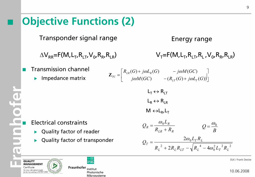
Objective Functions (2)
Transmission channelImpedance matrix
Electrical constraintsQuality factor of reader
Quality factor of transponder
Energy rangeTransponder signal range
ΔVRR=F(M,LT,RLT,V0,RR,RLR) VT=F(M,LT,RLT,RL ,V0,RR,RLR)
⎥⎦
⎤⎢⎣
⎡+−
−+=
))()(()()()()(GLjGRGCMj
GCMjGLjGR
TLT
RLRTC ωω
ωωZ
LT ↔ RLT
LR ↔ RLR
M ↔LR,LT
RLR
RR RR
LQ
+= 0ω
2220
42
0
42
2
LTLLTLL
LTT
RLRRRR
RLQ
ω
ω
−−+=
BQ 0ω=
Frau
nh
ofe
r
DLK / Frank Deicke
10.06.2008
10
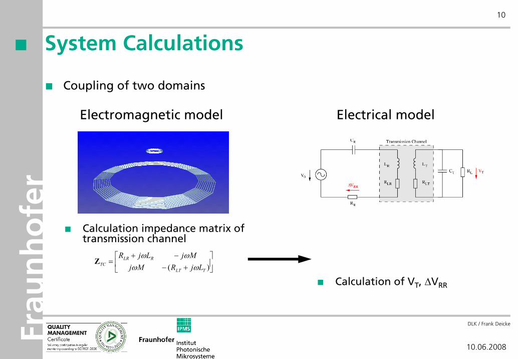
System Calculations
Coupling of two domains
Calculation impedance matrix of transmission channel
Electromagnetic model Electrical model
Calculation of VT, ΔVRR
⎥⎦
⎤⎢⎣
⎡+−
−+=
)( TLT
RLRTC LjRMj
MjLjRωω
ωωZ
Frau
nh
ofe
r
DLK / Frank Deicke
10.06.2008
11
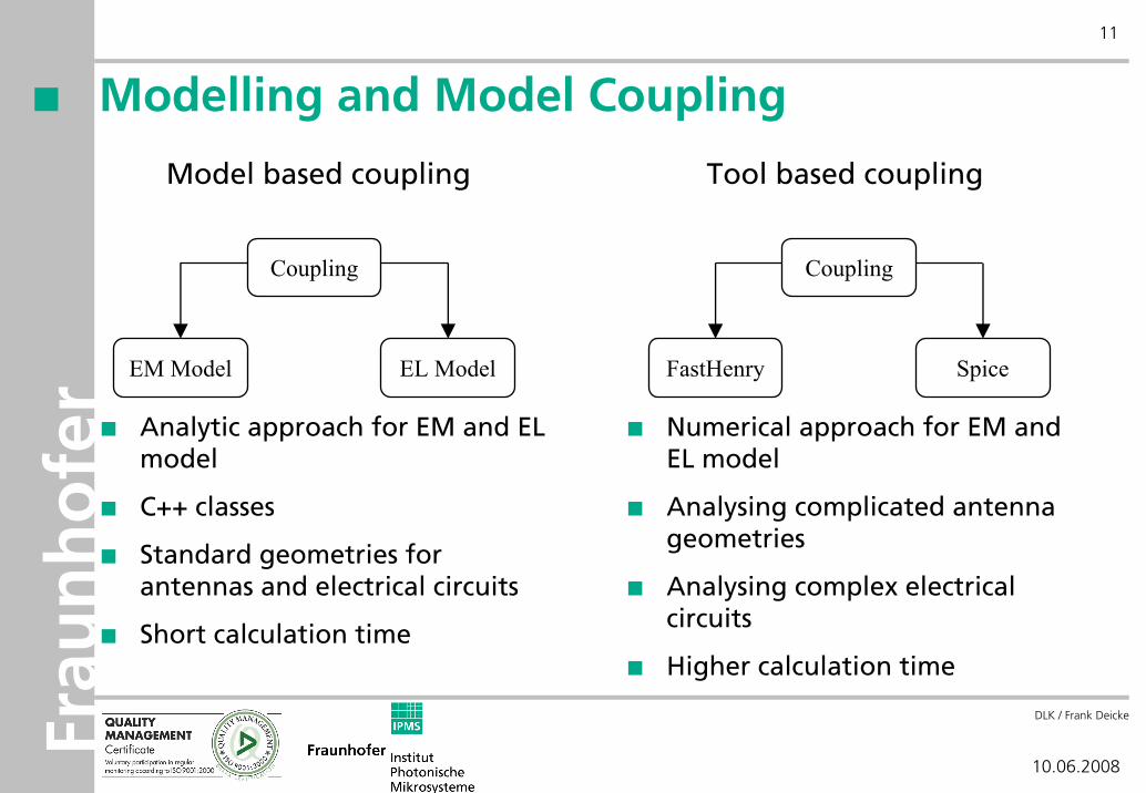
Modelling and Model Coupling
Model based coupling Tool based coupling
EM Model EL Model
Coupling
FastHenry Spice
Coupling
Analytic approach for EM and EL model
C++ classes
Standard geometries for antennas and electrical circuits
Short calculation time
Numerical approach for EM and EL model
Analysing complicated antenna geometries
Analysing complex electrical circuits
Higher calculation time
Frau
nh
ofe
r
DLK / Frank Deicke
10.06.2008
12
Optimisation
Goal: Find optimal parameter set for transponder system
Dimensioning of reader and transponder antenna
Adaptation of electrical circuit
Optimisation method
Find extremes
Find area of valid systems
Optimisation method depends on
Properties of objective functions
Properties of parameter space
Robust, reliable strategy
Minimise calculation time/cost
Frau
nh
ofe
r
DLK / Frank Deicke
10.06.2008
13
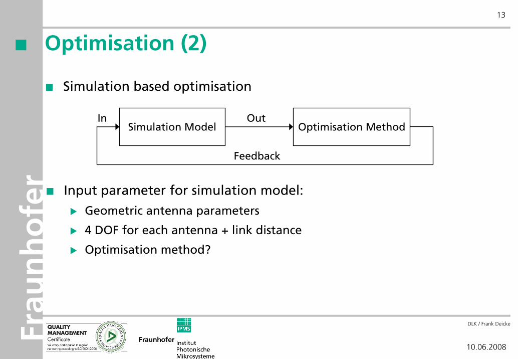
Optimisation (2)
Simulation based optimisation
Simulation Model Optimisation MethodIn Out
Input parameter for simulation model:
Geometric antenna parameters
4 DOF for each antenna + link distance
Optimisation method?
Feedback
Frau
nh
ofe
r
DLK / Frank Deicke
10.06.2008
14
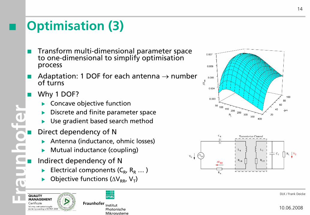
Optimisation (3)
Transform multi-dimensional parameter space to one-dimensional to simplify optimisation process
Adaptation: 1 DOF for each antenna → number of turns
Why 1 DOF?Concave objective functionDiscrete and finite parameter space Use gradient based search method
Direct dependency of NAntenna (inductance, ohmic losses)Mutual inductance (coupling)
Indirect dependency of NElectrical components (CR, RR … )Objective functions (ΔVRR, VT)
Frau
nh
ofe
r
DLK / Frank Deicke
10.06.2008
15
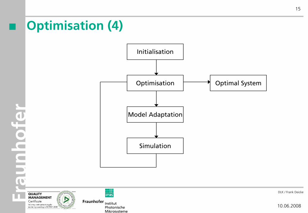
Optimisation (4)
Initialisation
Optimisation
Model Adaptation
Simulation
Optimal System
Frau
nh
ofe
r
DLK / Frank Deicke
10.06.2008
16
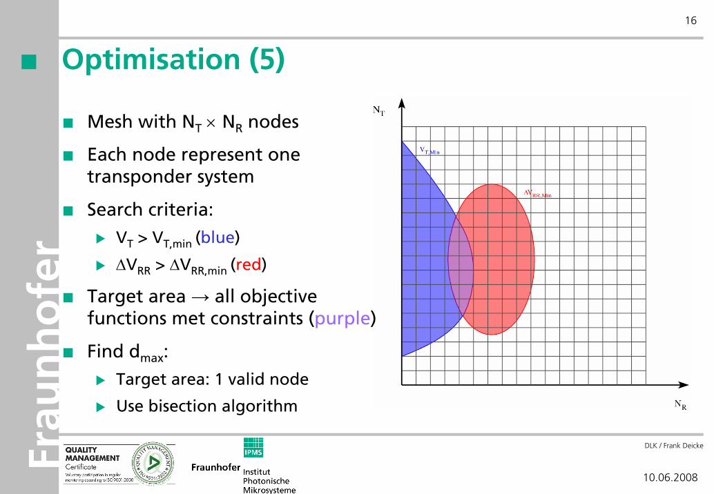
Optimisation (5)
Mesh with NT × NR nodes
Each node represent one transponder system
Search criteria:
VT > VT,min (blue)
ΔVRR > ΔVRR,min (red)
Target area → all objective functions met constraints (purple)
Find dmax:
Target area: 1 valid node
Use bisection algorithm
Frau
nh
ofe
r
DLK / Frank Deicke
10.06.2008
17
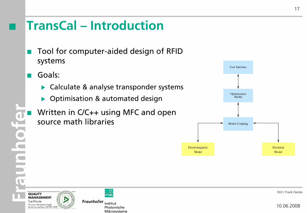
TransCal – Introduction
Tool for computer-aided design of RFID systems
Goals:
Calculate & analyse transponder systems
Optimisation & automated design
Written in C/C++ using MFC and open source math libraries
Frau
nh
ofe
r
DLK / Frank Deicke
10.06.2008
18
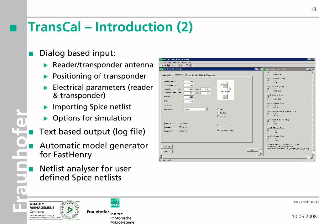
TransCal – Introduction (2)
Dialog based input:Reader/transponder antenna
Positioning of transponder
Electrical parameters (reader & transponder)
Importing Spice netlist
Options for simulation
Text based output (log file)
Automatic model generator for FastHenry
Netlist analyser for user defined Spice netlists
Frau
nh
ofe
r
DLK / Frank Deicke
10.06.2008
19
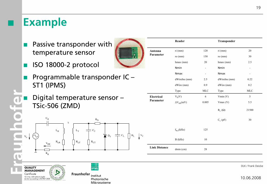
Example
Passive transponder with temperature sensor
ISO 18000-2 protocol
Programmable transponder IC –ST1 (IPMS)
Digital temperature sensor –TSic-506 (ZMD)
Reader Transponder
ri (mm) 120 ri (mm) 20
ro (mm) 150 ro (mm) 30
hmax (mm) 20 hmax (mm) 2.5
Nmin - Nmin -
Nmax - Nmax -
dWireIns (mm) 2.5 dWireIns (mm) 0.22
dWire (mm) 0.9 dWire (mm) 0.2
Type MLC Type MLC
V0(V) 6 Vmin (V) 5
ΔVRR(mV) 0.005 Vmax (V) 5.5
RL (Ω) 21500
CL (pF) 30
fRes(kHz) 125
B (kHz) 10
Link Distance dmin (cm) 28
Electrical Parameter
Antenna Parameter
Frau
nh
ofe
r
DLK / Frank Deicke
10.06.2008
20
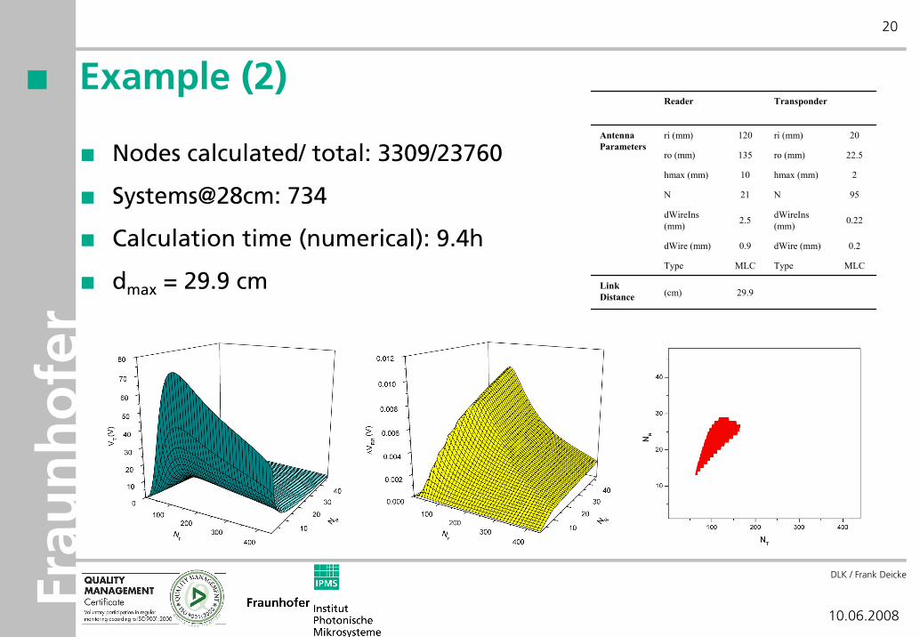
Example (2)
Nodes calculated/ total: 3309/23760
Systems@28cm: 734
Calculation time (numerical): 9.4h
dmax = 29.9 cm
Reader Transponder
ri (mm) 120 ri (mm) 20
ro (mm) 135 ro (mm) 22.5
hmax (mm) 10 hmax (mm) 2
N 21 N 95
dWireIns(mm) 2.5 dWireIns
(mm) 0.22
dWire (mm) 0.9 dWire (mm) 0.2
Type MLC Type MLC
Link Distance (cm) 29.9
Antenna Parameters
Frau
nh
ofe
r
DLK / Frank Deicke
10.06.2008
21
Conclusion
Antenna design and system optimisation can be done using
Analytical and numerical models for calculation
Coupling of electromagnetic and electrical domains
Simulation based optimisation method
Adapted parameter space
All methods and algorithms can be combined and controlled by onetool providing a computer-aided design process

Frau
nh
ofe
r
DLK / Frank Deicke
10.06.2008
22
Dipl.-Ing. Frank DeickeFraunhofer Institute for Photonic Microsystems
Lifetronics / Wireless Communication
Phone: +49 (0) 351 8823-214
Email: [email protected]
Dr.-Ing. Hagen GrätzFraunhofer Institute for Photonic Microsystems
Lifetronics / Wireless Communication
Phone: +49 (0) 351 8823-217
Email: [email protected]
Prof. Dr.-Ing. Wolf-Joachim FischerTechnische Universität Dresden
Institut für Halbleiter- und Mikrosystemtechnik
Phone: +49 (0) 351 46336336
Email: [email protected]
Contact