fracture mechanics of hybrid composites with ductile
TRANSCRIPT
HAL Id: hal-02006406https://hal.archives-ouvertes.fr/hal-02006406
Submitted on 4 Feb 2019
HAL is a multi-disciplinary open accessarchive for the deposit and dissemination of sci-entific research documents, whether they are pub-lished or not. The documents may come fromteaching and research institutions in France orabroad, or from public or private research centers.
L’archive ouverte pluridisciplinaire HAL, estdestinée au dépôt et à la diffusion de documentsscientifiques de niveau recherche, publiés ou non,émanant des établissements d’enseignement et derecherche français ou étrangers, des laboratoirespublics ou privés.
Fracture mechanics of hybrid composites with ductilematrix and brittle fibers: Influence of temperature and
constraint effectBenoît Vieille, Juan-Daniel Pujols Gonzalez, Christophe Bouvet
To cite this version:Benoît Vieille, Juan-Daniel Pujols Gonzalez, Christophe Bouvet. Fracture mechanics of hybrid com-posites with ductile matrix and brittle fibers: Influence of temperature and constraint effect. Journalof Composite Materials, SAGE Publications, 2018, pp.0. �10.1177/0021998318802613�. �hal-02006406�

�
�������������������������� �������������������������������������������������������
�������������������������������������
���������������������������������������������
������ �� ��� ���� ����� ��������� ����� �������� ���� ��� � ��� ���� ��������
���������������� �������������������������������������������������
�������������������������������������������������
����������������� ��
�
�
�
�
������������ ���
an author's https://oatao.univ-toulouse.fr/21847
https://doi.org/10.1177/0021998318802613
Vieille, Benoit and Pujols Gonzalez, Juan-Daniel and Bouvet, Christophe Fracture mechanics of hybrid composites
with ductile matrix and brittle fibers: Influence of temperature and constraint effect. (2018) Journal of Composite
Materials. ISSN 0021-9983

Fracture mechanics of hybridcomposites with ductile matrix andbrittle fibers: Influence of temperatureand constraint effect
B Vieille1 , J-D Gonzalez1 and C Bouvet2
Abstract
The fracture behavior of hybrid carbon and glass fiber woven-ply reinforced polyether ether ketone thermoplastic quasi-
isotropic laminates is investigated. Single-edge-notch bending and single-edge-notch tensile tests were conducted at
room temperature and at a temperature higher than the glass transition temperature (Tg) to study the influence of both
the constraint effect and the temperature on the strain energy release rate in laminates with ductile polyether ether
ketone matrix and brittle fibers. As failure is primarily driven by fibers breakage in tension (single-edge-notch tensile test)
and in tension/compression (single-edge-notch bending), it turns out that a temperature increase has very little influence
on the mode I critical translaminar fracture toughness KIc though the ductility of polyether ether ketone matrix is
exacerbated at T> Tg. It also appears that the constraint effect has very little influence on KIc as single-edge-notch tensile
test and single-edge-notch bending specimens have virtually the same mean value (about 45MPa. mp
). Single-edge-notch
bending specimens being characterized by a gradual failure, the G-R curves were derived from the computation of the
compliance loss and the corresponding gradual crack growth in agreement with the ASTM standard E1820. From the
evolution of the G-R curves at high temperature, the highly ductile behavior of the polyether ether ketone matrix at
T> Tg provides a good intrinsic toughness to the material, and the bridging of translaminar crack by the glass fibers at the
outer surfaces of laminates contribute to a moderate increase in its extrinsic toughness.
Keywords
Fracture mechanics, high temperature, mechanical testing, R-curves, thermoplastic
Introduction
In a material, fracture toughness is classically defined asthe energy required to extend a crack, in other wordsto resist fracture under mechanical loading by means oflocally dissipative behaviors (e.g. plastic deformation ordamage mechanisms). In notched structures, plasticand damage deformation mechanisms are instrumentalin redistributing the overstresses around the notch, andtherefore in modifying their fracture behavior.1 3 Earlyin the seventies, it was shown that the fracture tough-ness of engineering materials is improved by introdu-cing tough fibers into a brittle matrix,4 or brittle fibersinto a ductile matrix.5 In polymer matrix composites(PMCs), it is also well accepted that the insertion of aductile resin-rich layer between laminates’ layers isfound to increase significantly their fracture resistance,without altering its dependence on crack growth rate.6,7
The fiber/matrix adhesion also plays a major role infracture toughness as the adhesion rules the overstressprofiles in the vicinity of the fiber/matrix interface.8
In brittle matrices polymer composites, a too stronginterface discourages additional energy absorbingmechanisms such as fiber bridging and breakage.3 Intough matrices polymer composites, the strong fiber/matrix interface is necessary to allow extensive deform-ation of the matrix in order to fully utilize the intrinsicmatrix toughness.9 The question is still open when it
1INSA Rouen, Groupe de Physique des Materiaux, France2Institut Clement Ader, Universite de Toulouse, France
Corresponding author:
B Vieille, INSA Rouen avenue de l’universite St Etienne du Rouvray, 76801
France.
Email: [email protected]

comes to evaluate the influence of temperature and con-straint effect on the translaminar fracture toughness ofductile thermoplastic (TP)-based composites with brit-tle fibers.8,10,11 When a notched laminate is loaded intension, a Fracture Process Zone (FPZ) is observed atthe notch tip,12 and gradually grows with increasingload (Figure 1). Depending on stacking sequence andconstitutive materials, the crack path observed in fiber-reinforced polymer laminates is often complex. Thecrack propagates at a critical load, and the translami-nar crack growth resulting from an initial transversenotch is usually self-similar (Figure 2) in quasi-isotropicbrittle laminates.13 16 Thus, the extension of a self-
similar translaminar crack allows a global analysisbased on a global strain energy-release rate that is com-puted from tensile loading.14 17
In most engineering materials, the fracture resistancedepends on their microstructure by means of two pri-mary toughening (intrinsic and extrinsic) mechanisms.1
As pointed by Launey et al.,3 single-value parameters(such as the mode I critical stress intensity factor KIc)based on crack initiation are classically used to quantifyintrinsic toughness (associated with the nature of theconstituents and the reinforcement architecture).However, these parameters cannot always capture theability of a microstructure to develop toughening mech-anisms acting either ahead or behind the crack tip. Thefracture toughness of fiber-reinforced composites isimproved by increasing both micro- and meso-structural resistances by changing the nature of con-stituents, the fibers and matrix distribution and/or theinterface properties to suppress damage (primarilymicro-cracking and fiber breakage) ahead of the cracktip. These changes represent intrinsic toughening andare instrumental in increasing the fracture toughness ofductile materials. On the contrary, the fracture of brittlematerials is characterized by micro- and meso-struc-tural mechanisms. These mechanisms result in effect-ively reducing the crack-driving force at the crack tipby dissipating mechanical energy by means of localplastic deformation, damage mechanisms, and fibersbridging (primarily associated with local debondingand fibers pull-out). These mechanisms representextrinsic toughening also known as crack-tip shielding.3
Contrary to intrinsic toughness, extrinsic toughness isoften developed primarily during crack growth result-ing from crack-tip shielding mechanisms that result inrising R-curve behavior.
Figure 2. Crack growth in single edge notch laminates (Adapted from Jones13): (a) Self similar and (b) nonself similar.
Figure 1. Typical fracture process zone at a sharp crack in
single edge notch composites loaded in opening mode.12

The modes of energy dissipation are mainly affectedby the matrix fracture mode (brittle or ductile). This ismainly determined by the loading rate or temperatureconditions in the literature.18 20
The energy dissipated during controlled crackpropagation in fiber-reinforced composites is usuallyevaluated in terms of different source mechanisms:plastic deformation, fiber-snapping, matrix-cracking,and fiber pull-out.13,15,21 In composite materials witha brittle matrix, the energies dissipated during crackinitiation and propagation in the composite with aweak fiber/matrix interface are derived principallyfrom the work of fiber pull-out (resulting from the fric-tional forces that hold a broken fiber in its matrixsocket). In ductile matrix composite systems, the localplastic deformation of the matrix must also be takeninto account in the total fracture toughness.19,22 Themechanical behavior of polymer resins exhibits tem-perature dependence (viscoelastic and viscoplasticbehaviors) not only above glass transition temperature(Tg) but also below Tg. Kim and Phoa22 have studiedthe influence of temperature on interfacial debondingon composites with TP-coated carbon fibers. In the lateeighties, the elevated-temperature dependence of frac-ture energy mechanisms of hybrid carbon-glass fiberreinforced epoxy composites was studied by Munroand Lai,20 who concluded that the work of fractureincreased with temperature and glass fiber content.Indeed, the post-debond friction energy term wasshown to be dominant, resulting from an extensivefrictional work of the post-debond sliding type afterglass fiber failure, in addition to that from the glass-fiber pull-out mechanism. Besides, the reinforcementarchitecture (UD or woven fabrics) also appears to sig-nificantly influence the extrinsic toughness ofPMCs.23,24 The influence of temperature on the inter-laminar fracture toughness of TP-based composites waswidely investigated in unidirectional composites asreviewed in previous studies,7,8 and more specificallyin the case of woven-ply laminates.7,22 However, tothe authors’ best knowledge, there are no referencesdealing with the influence of temperature on translami-nar failure.
This study deals with the fracture mechanics ofhybrid laminated composites consisting of highly duc-tile TP matrix (polyether ether ketone (PEEK)) andbrittle fibers. The effect of temperature and constrainteffect on the strain energy release rate and crack exten-sion of the laminates are specifically addressed in thecase of a mode I translaminar failure mode. On the onehand, tests are carried out at room temperature (RT)and at 150�C (i.e. slightly higher than Tg as theductile behavior of PEEK matrix is exacerbated) toexamine the influence of temperature on fractureenergy. On the other hand, tests are conducted on
single-edge-notch tensile test (SENT) and single-edge-notch bending (SENB) specimens with different ratioa/w to investigate the influence of constraint effecton fracture toughness. The G-R curves were derivedfrom the computation of the compliance loss andthe crack extension in agreement with the ASTM stand-ard E1820.
Specimen description and test procedures
Materials
The laminated plates obtained by thermo-compressionare made up of carbon (Tenax�-E HTA40 3K)–PEEK5HS woven plies prepregs and glass–PEEK prepregs(Table 1). The consolidated laminates consist of 14inner carbon-PEEK plies and two outer glass-PEEKplies.25 The two outer glass-PEEK plies are consideredfor electrical protection purposes. In addition, thecarbon and glass fiber fabrics are balanced in thewarp and weft directions. The stacking sequence oflaminates is quasi-isotropic (as shown in Figure 3):[(0/90)G,[(0/90),(�45)]3,(0/90)]s (with G index for glassfibers ply). The average thickness of laminates is about4.5mm. The single-edge-notch test specimens (tensileand bending) were cut by water jet from600� 600mm2 plates (Figure 4). The machining ofthe single-edge notches was done by means of a preci-sion endless diamond wire saw whose radius was0.085mm. The initial notch length to specimen widthratio a/w ranges from 0.2 to 0.5 in both SENT andSENB specimens.
Methods and experimental set-up
Thermo-mechanical testing. All the tests were performedusing a 100 kN capacity load cell of an MTS 810 servo-hydraulic testing machine in displacement-controlled
Table 1. A few properties of woven carbon and glass fibers
reinforced PEEK elementary ply at RT.
Carbon/
PEEK
Glass/
PEEK
Ex (GPa) 60 22
Ex (GPa) 60 20
Gxy (GPa) 4.8 6.55
vxy 0.04 0.04
Tensile strength (warp) (MPa) 963 1172
Compressive strength (warp) (MPa) 725 1103
Nominal ply thickness (mm) 0.31 0.08
Tg (�C) 145 145
PEEK: polyether ether ketone; RT: room temperature.

mode and with a temperature control system. Tensileand three-point bending loadings were applied tonotched specimens at RT and 150�C.
Three specimens were tested in each configuration toobtain an acceptable average value. The tensile mech-anical properties were determined according to theEuropean standards EN 6035.26 In SENT specimens,the longitudinal modulus ðEXÞ and ultimate strength�uð Þ were calculated from the following definitions
EX ¼�F
S:�"Xand �u ¼
Fu
Sð1Þ
where �F is the difference in the applied tensile loads at"Xð Þ2 ¼ 0:25% and "Xð Þ1 ¼ 0:05%,S is the specimen cross section,�"X ¼ "Xð Þ2 � "Xð Þ1 is the difference in the
longitudinal strains obtained from a blade-extensometer,
Fu is the maximum force borne by the specimen atfailure.
The mechanical properties of C/PEEK and G/PEEKelementary plies are specified in Table 1.25
The mechanical properties in bending were deter-mined according to the European standards EN
Figure 3. Optical micrograph of the longitudinal section revealing the quasi isotropic stacking sequence of the laminates.
Figure 4. Geometry of single edge notched tensile specimens: (a) Tensile specimens and (b) bending specimens.
2562.27 The bending strain and stress are defined asfollows
"bending ¼6dw
s2and �bending ¼
3Ps
2bw2ð2Þ
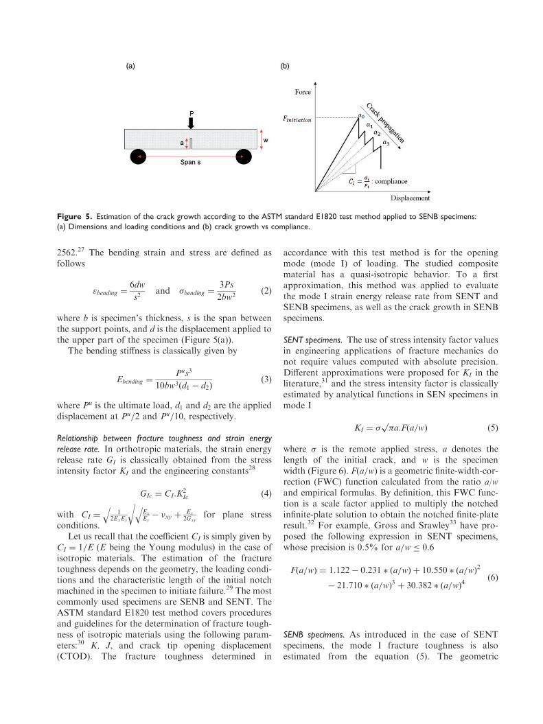
where b is specimen’s thickness, s is the span betweenthe support points, and d is the displacement applied tothe upper part of the specimen (Figure 5(a)).
The bending stiffness is classically given by
Ebending ¼Pus3
10bw3ðd1 � d2Þð3Þ
where Pu is the ultimate load, d1 and d2 are the applieddisplacement at Pu=2 and Pu=10, respectively.
Relationship between fracture toughness and strain energy
release rate. In orthotropic materials, the strain energyrelease rate GI is classically obtained from the stressintensity factor KI and the engineering constants28
GIc ¼ CI:K2Ic ð4Þ
with CI ¼1
2ExEy
qEx
Ey
q� �xy þ
Ex
2Gxy
rfor plane stress
conditions.Let us recall that the coefficient CI is simply given by
CI ¼ 1=E (E being the Young modulus) in the case ofisotropic materials. The estimation of the fracturetoughness depends on the geometry, the loading condi-tions and the characteristic length of the initial notchmachined in the specimen to initiate failure.29 The mostcommonly used specimens are SENB and SENT. TheASTM standard E1820 test method covers proceduresand guidelines for the determination of fracture tough-ness of isotropic materials using the following param-eters:30 K, J, and crack tip opening displacement(CTOD). The fracture toughness determined in
accordance with this test method is for the openingmode (mode I) of loading. The studied compositematerial has a quasi-isotropic behavior. To a firstapproximation, this method was applied to evaluatethe mode I strain energy release rate from SENT andSENB specimens, as well as the crack growth in SENBspecimens.
SENT specimens. The use of stress intensity factor valuesin engineering applications of fracture mechanics donot require values computed with absolute precision.Different approximations were proposed for KI in theliterature,31 and the stress intensity factor is classicallyestimated by analytical functions in SEN specimens inmode I
KI ¼ � �ap
:F a=wð Þ ð5Þ
where � is the remote applied stress, a denotes thelength of the initial crack, and w is the specimenwidth (Figure 6). Fða=wÞ is a geometric finite-width-cor-rection (FWC) function calculated from the ratio a/wand empirical formulas. By definition, this FWC func-tion is a scale factor applied to multiply the notchedinfinite-plate solution to obtain the notched finite-plateresult.32 For example, Gross and Srawley33 have pro-posed the following expression in SENT specimens,whose precision is 0.5% for a=w � 0:6
F a=wð Þ ¼ 1:122� 0:231 � a=wð Þ þ 10:550 � a=wð Þ2
� 21:710 � a=wð Þ3þ 30:382 � a=wð Þ
4ð6Þ
SENB specimens. As introduced in the case of SENTspecimens, the mode I fracture toughness is alsoestimated from the equation (5). The geometric
Figure 5. Estimation of the crack growth according to the ASTM standard E1820 test method applied to SENB specimens:
(a) Dimensions and loading conditions and (b) crack growth vs compliance.

finite-width-correction function F a=wð Þ is calculatedfrom the ratio a/w and empirical formulas whose pre-cision is 0.5% for any ratio a=w31
F a=wð Þ ¼1
�p :
½1:99� ða=wÞð1� a=wÞ
ð2:15� 3:93 � awþ 2:7 � a=wð Þ
2�
ð1þ 2 � a=wÞð1� a=wÞ3=2ð7Þ
In SENB specimens, the ASTM standard E1820 testmethod gives an estimation of the crack growth versusapplied stress.30 Thus, the crack length on an SENBspecimen is normally determined from crack openingcompliance. According to the ASTM standard, it isdetermined from load-line compliance if the correctcalibration is available. For a resistance curve test
method using an elastic compliance technique(Figure 5(b)) on single-edge bend specimens withcrack opening displacements measured at the notchededge, the crack length ai is given as follows
ai=w ¼ ½0:999748� 3:9504uþ 2:9821u2
� 3:21408u3 þ 51:51564u4 � 113:031u5�ð8Þ
where u ¼ 1BWECiS=4
� �1=2þ1
and B and W are the specimen thickness and width,respectively,
E is the longitudinal stiffness,Ci ¼ ð�vm=�PÞ is the crack opening compliance (the
ratio of displacement increment to load increment)
Figure 6. Longitudinal stress in the vicinity of the crack tip in QI SEN laminates loaded in mode I.

obtained from the crack opening displacement atnotched edge vm and the applied load P,
S is the specimen span, the distance between speci-men supports (Figure 5(a)).
Finally, the expression of �y at the crack tip(Figure 6) is used to estimate the stress concentrationfactor KT for mode-I type loading29
KT ¼�y � ¼ 0ð Þ
��x¼0
�¼
a
2r
r:Fða=wÞ ð9Þ
where r ¼ 0:085 mm is the radius of the notch at thecrack tip and � is the remote applied stress far from thenotch.
Fractographic analyses. Damage mechanisms are dis-cussed by means of fractographic analyses: macro-scopic observations with a Keyence opticalmicroscope and tomographic observations with a
Microtomograph Easytom 130 supplied by the com-pany RX Solutions.
Results and discussion
Macroscopic mechanical response and fracturebehavior
From the macroscopic response standpoint, bothSENT and SENB specimens exhibit a brittle failure atRT with a tendency to shift towards a quasi-brittle fail-ure (Figures 7 and 8) as the initial notch length-to-spe-cimen width ratio a/w (typically from 0 to 0.5) and testtemperature increase. As the ratio a/w increases, thestress concentration factor computed from equations(6, 7, 9) gradually increases at the crack tip (Figure9). In SENT specimens, the influence of stress concen-tration is about the same with an 80% decrease in the
Figure 7. Constraint effect on SENT specimens: (a) RT and (b) 150�C.
SENT: single edge notch tensile; RT: room temperature.

Figure 8. Constraint effect on SENB specimens: (a) RT and (b) 150�C.
SENB: single edge notch bending; RT: room temperature.
Figure 9. Influence of temperature and constraint effect (quantified by the stress concentration factor) on the residual strength of
QI laminates: (a) SENT and (b) SENB.
SENT: single edge notch tensile; SENB: single edge notch bending.

residual strength at both temperatures (Figure 9(a)). InSENB specimens, the constraint effect (quantified bythe stress concentration factor Kt) decreases the resi-dual strength by virtually 80% and 70% at RT and150�C, respectively (Figure 9(b)). In both SENT andSENB specimens, the influence of temperature on theresidual strength is limited. The decrease in the residualstrength along with an increasing a/w ratio appears tobe hyperbolic in SENT specimens and linear in SENBspecimens.
In both SENT and SENB specimens, the micro-scopic observations of failure surfaces clearly showthat fracture is translaminar in mode I loading evenat elevated temperature (Figures 10 and 11) regardlessof the a/w ratio. At RT, translaminar fracture isobserved in all specimens. The front views indicatethat the macroscopic translaminar macroscopic crackgrows self-similarly with respect to the initial notch inSENT specimens. In SENB specimens with low a/wratio, the translaminar crack is not self-similar.
In SENT specimens, failure is primarily dominatedby the tensile breakage of 0� carbon fibers, with novisible contribution of the þ/�45� plies suggestingthat the quasi-brittle failure observed at 150�C is
primarily resulting from some fiber/matrixdebonding coming along with fibers pull-out (edgeviews Figure 10).
In SENB specimens, failure consists of tensile andcompressive breakage of 0� carbon fibers particularly inspecimens with low a/w ratio (Figure 11). When loadedin bending, the upper part of specimens (above the neu-tral axis) is subjected to compression whereas the lowerpart (below the neutral axis) is subjected to tension. Inaddition, local crushing of the upper edges is observedin the contact area. As a/w ratio increases (typicallyfrom a/w¼ 0.3), the stress concentration factor Kt
increases as well (Figure 9(b)), and promotes a transla-minar failure dominated by the tensile breakage of 0�
carbon fibers. No visible damage is observed on upperedges of these specimens as the bending stress is lowerthan the crushing stress.25 The gradual failure observedat 150�C is primarily associated with glass fibers brid-ging at the outer surfaces of specimens (Figure 12). Theultimate strength of G/PEEK plies being lower thanC/PEEK plies, glass fibers cannot take up the loadtransferred to neighboring fibers when carbon fibersfail. Thus, glass fiber bridging results from the debond-ing at the glass fiber/matrix interface as is observed on
Figure 10. Microscopic observations of SENT specimens after failure in mode I at 150�C.
SENT: single edge notch tensile.

the microscopic observation. As carbon fibers breakagecomes along with the crack mouth opening, gradualglass fibers pull-out may be observed behind the cracktip. In addition, temperature promotes local crushing(resulting from compression) in the contact area, andexacerbates ductility at T>Tg.
11,15 It therefore contrib-utes to the retardation of the crack extension and theincrease in the fracture toughness as will be furtherdiscussed in section ‘‘Influence of constraint effect onG-R curves’’.
Influence of temperature on G-R curves
Depending on the specimen’s geometry and the loadingmode, fiber-reinforced composites are generally charac-terized by an observable stable crack growth beforeinstability,34 and the fracture toughness (or criticalstrain energy release rate) usually increases with crackextension before reaching a plateau value (Figure 13).Thus, the critical fracture toughness Kc is not sufficient
to characterize the whole fracture behavior and theconcept of crack resistance curves (described as G-Rcurves) has to be adopted.35 Within the framework ofLEFM, the determination of G-R curves is thereforethe key point to quantify fracture in terms of energyrequired to grow a crack in quasi-isotropic laminates.In the present work, the idea was first to build equiva-lent G-R curves based on the evaluation of fracturetoughness for different ratios a/w and different loadings(e.g. tensile and bending). From equations (5–7), it ispossible to compute the value of the critical fracturetoughness KIc in SENT and SENB specimens(Figure 14). As failure is primarily driven by carbonfibers breakage in tension (SENT) and in tension/com-pression (SENB), it turns out that a temperatureincrease has very little influence on the critical transla-minar fracture toughness though the ductility of PEEKmatrix is exacerbated at T>Tg. It also appears that theconstraint effect has very little influence on the criticalmode I fracture energy as SENT and SENB specimens
Figure 11. Microscopic observations of SENB specimens after failure in mode I at 150�C.
SENB: single edge notch bending.

have virtually the same mean value (about 45MPa.mp
). With increasing ratio a/w, the strain energyrelease rate increases gradually in SENT specimens(Figure 14(a)), whereas it slowly increases and grad-ually decreases in SENB specimens, resulting fromless contribution of compressive failure (Figure 14(b)).
According to equation (8), the crack length ai iscomputed from the crack opening compliance asdescribed in ASTM standard E1820. Thus, the criticalstrain energy release rate in opening mode GIc is
classically obtained from the load-line complianceC ¼ d=P and the crack length (Figure 5(b))29
GI ¼P2
2B
dC
dað10Þ
where d represents the applied displacement, P the forceborne by the specimen, and B is the specimen width.
The G-R curves are drawn from this expression andthe translaminar crack extension (Figure 15). This
Figure 12. Illustration of crack extension and crack mouth opening displacement in SENB specimens at 150�C (a/w 0.3): influence
of fiber bridging on extrinsic toughness.
SENB: single edge notch bending.
Figure 13. Determination of the critical fracture toughness from R or J curves.16

technique was applied to the tests conducted at bothtemperatures. As will be discussed in section‘‘Translaminar failure in SENB specimens,’’ the grad-ual failure observed at high temperature is associatedwith glass fiber bridging. This contributes to theincrease in the extrinsic toughness, hence slowingdown the crack extension (Figure 12). The equivalent
G-R curves built from equation (4) and the fracturetoughness at crack initiation KI corresponding to dif-ferent ratio a/w (Figure 14) are reported in Figure 15 interms of strain-energy release rate in both test tempera-tures. It is therefore possible to compare the evolutionof the strain energy release vs crack propagation withthe values of GI init at crack initiation computed fromdifferent ratio a=w. The values at initiation computedfrom LEFM equations31 are in agreement with thevalues obtained during propagation from the compli-ance loss (ASTM standard E1820). As indicated previ-ously, a temperature increase to temperatures higherthan Tg has little influence on the translaminar fracturetoughness, and the mean value of GIc (computed fromequation (4)) slightly increases at 150�C (from 41 kJ/m2
to 44 kJ/m2, hence a 7% increase) because the mechan-ical properties of the equivalent orthotropic materialslightly change between RT and 150�C resulting fromthe softening of the PEEK matrix (Table 2).
Influence of constraint effect on G-R curves
In PMCs, Allaer et al.36 have studied the influence ofthe constraint effect during fracture toughness tests bymeans of SENB specimens in order to define a validplane strain fracture toughness value KIc. The influenceof crack tip constraint effect (depending on the speci-men geometries and the loading conditions) and stress
Figure 14. Influence of temperature and constraint effect on the mode I fracture translaminar toughness of QI laminates: (a) SENT
and (b) SENB. SENT: single edge notch tensile;
SENB: single edge notch bending.
Figure 15. Evolution of strain energy release rate along with
the crack growth in SENB specimens with different ratio a/w:
(a) RT – (b) 150�C.
SENB: single edge notch bending; RT: room temperature.
Table 2. Mechanical properties of the equivalent orthotropic
material – Quasi isotropic CG/PEEK laminates.
Ex (GPa) Ex (GPa) Gxy (GPa) vxy C1 GPa�1� �
RT 49.58 49.58 15.76 0.289 0.0215
150�C 45.55 45.55 14.48 0.266 0.0236
PEEK: polyether ether ketone; RT: room temperature.

triaxiality (depending on the initial notch length to spe-cimen width ratio a/w) on ductile and brittle fracture isof major importance for the assessment of structuralintegrity. The loss of constraint effect is related to theposition and the size of the plastic zones. Indeed, thedeeper the notch and the higher the test temperature,the greater are the plastic zone and constraints (result-ing from the triaxial stress state). Therefore, the higherthe loading force must be to deform the sample.2 As aconsequence, it is usually observed that the decrease incrack tip constraint (the stress concentration at thenotch root is offset by plastic deformation) leads toan increase of the fracture toughness (correspondingto a ductile failure).
Translaminar failure in SENB specimens
As pointed in section ‘‘Macroscopic mechanicalresponse and fracture behaviour,’’ the fracture mechan-isms are modified at T>Tg because of glass fiber brid-ging behind the crack tip and local plastic deformationin matrix-rich areas ahead of the crack tip as transla-minar crack grows (Figure 12). It appears that bothmechanisms are enhanced when matrix ductilityincreases. Indeed, instead of the sudden breakage of0� carbon fibers at RT, the ductile behavior of thePEEK matrix at the fiber/matrix interface contributesto the dissipation of a portion of the mechanical energyduring the load transfer between a broken fiber bundleand the neighbor fibers.
In order to investigate more specifically the contri-bution of the 0� and þ/-45� oriented plies in quasi-iso-tropic CG/PEEK laminates, X-ray tomographic
observations were conducted in SENB specimens witha ratio a=w ¼ 0:3 (Figure 16). In 0� plies, a clear trans-laminar crack is observed suggesting the catastrophicfailure of 0� carbon fiber bundles initiated from thestress concentration in the vicinity of the initial notch.A local crushing (or compressive failure) of laminates’upper edges in the contact area with the upper cylinderis also observed. Inþ /-45� oriented plies, the fracturesurface reveals the breakage of þ/�45� carbon fibers inshearing. In QI laminates, the macroscopic failure isprimarily dominated by 0� fibers, resulting in a virtuallytemperature-independent behavior (even at T>Tg) astheþ /�45� oriented plies do not significantly contrib-ute to bear the mechanical loading. From the fracturemechanics standpoint, the translaminar failure isinitiated when the stress intensity factor in tensionreaches its critical value Ktension
Ic .A brittle interface allows crack advance by sudden
breakage of 0� carbon fibers, while a ductile interfaceforms a well-defined glass fiber-bridged crack poten-tially leading to divert the crack front and to reducecrack growth.34 After the failure of carbon fibers, thebroken glass fiber locally debonds from the matrix,and the matrix surrounding the broken fiber ends isstressed at a significantly higher level than prior to thefiber failure. The resulting temporary and local plasticdeformation of the matrix in this area comes alongwith a gradual pull-out of 0� glass fibers at 150�C asthe translaminar macroscopic crack grows, thereforeleading to glass fiber-bridging that reduces the crackmouth opening. At RT, pull-out is reduced as suddenbreakage of 0� carbon fibers does not allow the matrixto dissipate the mechanical energy by means of
Figure 16. Tomographic observations of SENB specimens (a/w 0.3) at 150�C.
SENB: single edge notch bending.

inelastic deformation and does not imply significantinterface debonding in the outer G/PEEK plies.These mechanisms are instrumental in ruling themechanical energy released during fracture. More spe-cifically, the strain energy release rate increases atmacroscopic scale resulting from enhanced ductilityof the PEEK matrix at microscopic and mesoscopicscales as temperature increases. In addition, a largernumber of glass fibers bridge the crack as it grows.Ultimately, such fiber-bridging results in increasing themode I translaminar toughness during the last stage offracture.
Influence of glass fibers on extrinsic toughness
SENB specimens are characterized by a gradual failure(particularly at 150�C as explained in section‘‘Translaminar failure in SENB specimens’’). G-Rcurves were derived from equation (10) and the corres-ponding gradual crack growth in agreement with theASTM standard E1820. It is therefore possible toobserve a sigmoid evolution of crack extension vstime (Figure 17). Until crack initiation at maximumstress (about 350 MPa for a 1.7% axial strain), thecrack length is virtually unchanged. Therefore, it sud-denly increases and jumps are clearly observed on thecurves obtained from the ASTM method. These jumpsare associated with the breakage of 0� carbon fibers.The stress redistribution to the neighboring fibers wasdescribed in details in section ‘‘Translaminar failure inSENB specimens’’. Both glass fiber bridging and localplastic deformation of the PEEK matrix at the interfaceand at the crack tip contributes to the momentary sta-bilization of the crack growth. At the end of loading,when the stress borne by specimens tends to low values(typically less than 100 MPa as shown on Figure 8(b)),it appears that there are no jumps (because all the 0�
fibers are broken), and the crack extension gradually
slows down as there are lots of bridged glass fibersbehind the crack tip reducing the crack mouth opening(microscopic observations on the left on Figure 12).Thus, the fracture process zone consists of two zones(behind and ahead of the crack tip) resulting from thedamage mechanisms taking place during translaminarcracking:35,37
1. The damage zone ahead of the advancing crack tipwhere matrix cracking, interfacial debonding, andpost-debonding friction occurs;
2. The glass fibers bridging zone or tied zone at thewake of the crack tip where glass fibers bridge theopposite fracture surfaces and pull-out.
These two zones are closely associated with bothintrinsic and extrinsic fracture toughness. In the presentcase, the highly ductile behavior of the PEEK matrix atT>Tg provides good intrinsic toughness to quasi-iso-tropic hybrid laminates, whereas the bridging of macro-scopic translaminar crack by the glass fibers at theouter surfaces of laminates contributes to the increasein its extrinsic toughness. This evolution of the G-Rcurve is in agreement with the observations proposedin previous studies:3 5,20,37 extrinsic toughness primar-ily contributes to the increase in the fracture energyduring crack growth by means of crack-tip shieldingmechanisms that result in rising R-curve behavior.
The purpose of the present work was not to specif-ically address the influence of hybridization on fracturetoughness (it will be investigated in a forthcomingpaper). However, the effect of the extrinsic tougheningby the glass fibers is indeed expected to be small. Forquantification purposes, the extrinsic toughening by theglass fibers is evaluated from tests on SENT specimens(with a ratio a/w¼ 0.3) consisting of carbon fiber rein-forced PEEK matrix laminated composites on the onehand and glass and carbon fiber reinforced PEEK
Figure 17. Evolution of the crack growth estimated by the
ASTM standard E1820 test method applied to SENB specimens
(a/w 0.3) at 150�C.
SENB: single edge notch bending.
Figure 18. Influence of outer glass fibers/PEEK laminates on
the tensile response of SENT specimens (a/w 0.3) at 150�C.
SENT: single edge notch tensile.

matrix composites on the other hand (Figure 18).From the macroscopic mechanical standpoint,the outer glass fiber PEEK plies have a moderate influ-ence. From these tests, the mode I fracture toughness isevaluated by equations (5) and (6). The results suggestthat glass fibers virtually do not influence KIc as itincreases from 50.04 to 53.06 MPa. m
p(hence a 6%
increase) in C/PEEK and CG/PEEK laminates,respectively.
Conclusions
Tensile and bending tests were conducted at RT and150�C (T>Tg) on single-edge notched specimens con-sisting of hybrid carbon glass reinforced PEEK com-posite materials. In the studied quasi-isotropiclaminates, the translaminar crack is dominated by thebreakage of 0� carbon fibers, and appears to be self-similar in both SENT and SENB specimens.
Equivalent G-R curves are obtained from SENT andSENB specimens with different initial notch length tospecimen width ratio a/w (typically from 0 to 0.5). Asfailure is primarily driven by carbon fibers breakage intension (SENT) and in tension/compression (SENB), itturns out that a temperature increase has very littleinfluence on the mode I critical translaminar fracturetoughness KIc though the ductility of PEEK matrix isexacerbated at T>Tg. It also appears that the con-straint effect has very little influence on KIc as SENTand SENB specimens have virtually the same meanvalue (about 45 MPa. m
p).
G-R curves were derived from the computation ofcrack growth and compliance loss in agreement withthe ASTM standard E1820. After reaching a plateauvalue, the critical strain energy release rate in mode Igradually increases as the translaminar crack ultimatelygrows. The late increase in translaminar toughnessresults from both intrinsic and extrinsic toughnessthat are specifically enhanced at T>Tg. The fractureenergy is associated with the brittle failure of carbonfibers leading to gradual fiber bridging of glass fibers(contributing to a reduced extrinsic toughness), whereasthe highly ductile PEEK matrix provides the compositematerial its intrinsic toughness by means of local plasticdeformation at the crack tip and around the brokenfibers ends.
Declaration of Conflicting Interests
The author(s) declared no potential conflicts of interest withrespect to the research, authorship, and/or publication of thisarticle.
Funding
The author(s) received no financial support for the research,authorship, and/or publication of this article.
ORCID iD
B Vieille http://orcid.org/0000 0003 4528 7167
References
1. Ritchie RO. Mechanisms of fatigue crack propagation in
ductile and brittle solids. Int J Fract 1999; 100: 55 83.
2. Hertzberg RW, Vinci RP and Hertzberg JL. Element offracture mechanics. In: Hertzberg RW (ed.) Deformation
and fracture mechanics of engineering materials, 5th ed.
Hoboken, USA: Wiley & Sons, 1996.3. Launey ME and Ritchie RO. On the fracture toughness
of advanced materials. Adv Mater 2009; 21: 2103 2110.4. Tardiff G. Fracture mechanics of brittle matrix ductile
fiber composites. Eng Fract Mech 1973; 5: 1 10.
5. Naerheim Y. Fracture characteristics of a ductilematrix/brittle fiber composite. Metall Transact A 1976;
7: 63 70.6. Kim JK and Mai YW. The effect of interfacial coating
and temperature on the fracture behaviours of unidirec
tional KFRP and CFRP. J Mater Sci 1991; 26:
4701 4720.7. Fracasso R, Rink M, Pavan A, et al. The effects of strain
rate and temperature on the interlaminar fracture tough
ness of interleaved PEEK/CF composites. Compos Sci
Technol 2001; 61: 57 63.8. Jacob GC, Starbuck JM, Fellers JF, et al. The effect of
loading rate on the fracture toughness of fiber reinforced
polymer composites. J Appl Polymer Sci 2005; 96:899 904.
9. Kassapoglou C. Modeling the effect of damage in compos
ite structures: simplified approaches, 1st ed. Chichester,UK: John Wiley & Sons Ltd, 2015, pp.41 56.
10. Laffan MJ, Pinho ST, Robinson P, et al. Translaminarfracture toughness testing of composites: a review. Polym
Test 2012; 31: 481 489.
11. Vieille B. Evolution of the strain energy release rateduring ductile or brittle failure in woven ply reinforced
thermoplastic laminates under high temperature condi
tions. Polym Compos 2018. DOI: 10.1002/pc.24612.12. Reifsnider KL. Damage and damage mechanics.
In: Reifsnider KL (ed.) Fatigue of composite materials.
Amsterdam, The Netherlands: Elsevier Science
Publishers BV, 1990, pp.11 78.13. Jones RM. Other analysis and behavior topics. In:
Mechanics of composite materials, 2nd ed. London, UK:
Taylor & Francis, 1999, p.345.14. Harris B. A historical review of the fatigue behavior of
fiber reinforced plastics. In: Harris B (ed.) Fatigue in com
posites science and technology of the fatigue response offiber reinforced plastics. Woodhead Publishing, 2003,
pp.3 35.15. Wells JK and Beaumont PWR. Crack tip energy absorp
tion processes in fibre composites. J Mater Sci 1985; 20:
2735 2749.16. Vieille B, Chabchoub M, Bouscarrat D, et al. A fracture
mechanics approach using acoustic emission technique to
investigate damage evolution in woven ply thermoplastic
structures at temperatures higher than glass transition
temperature. Compos B 2017; 116: 340 351.

17. Vieille B, Chabchoub M and Gautrelet C. Influence ofmatrix ductility and toughness on strain energy releaserate and failure behavior of woven ply reinforced thermo
plastic structures at high temperature. Compos B Eng2018; 132: 125 140.
18. Beaumont PWR. Physical modelling of damage development in structural composite materials under stress.
In: Harris B (ed.) Fatigue in composites: science and technology of the fatigue response of fiber reinforced plastics.Cambridge: Woodhead Publishing Ltd., 2003,
pp.365 412.19. Lauke B and Pompe W. Fracture toughness of short fibre
reinforced thermoplastics. Compos Sci Technol 1986; 26:
37 57.20. Munro M and Lai CPZ. The elevated temperature
dependence of fracture energy mechanisms by hybrid
carbon glass fiber reinforced composites. J Mater Sci1988; 26: 4701 4720.
21. Wells JK and Beaumont PWR. The prediction of Rcurves and notched tensile strength for composite lamin
ates. J Mater Sci 1987; 22: 1457 1468.22. Kim K Y and Phoa K M. Interlaminar fracture tough
ness of CF/PEI and GF/PEI composites at elevated tem
peratures. Appl Compos Mater 2004; 11: 173 190.23. Flore D, Stampfer B and Wegener K. Experimental and
numerical failure analysis of notched quasi unidirectional
laminates at room temperature and elevated temperature.Compos Struct 2017; 160: 128 141.
24. Ortega A, Maimı P, Gonzalez EV, et al. Translaminarfracture toughness of interply hybrid laminates under ten
sile and compressive loads. Compos Sci Technol 2017;143: 1 12.
25. Dubary N, Taconet G, Bouvet C, et al. Influence of tem
perature on the impact behavior and damage tolerance ofhybrid woven ply thermoplastic laminates for aeronautical applications. Compos Struct 2017; 168: 663 674.
26. Test standard EN 6035, Aerospace series Fiber reinforced plastics Test Method Determination ofnotched and unnotched tensile strength. Published by
the European Association of Aerospace Industries(AECMA), April 1996.
27. Test standard EN 2562, Aerospace series Carbon Fiberreinforced plastics Test Method Unidirectional laminates, flexural test parallel to the fiber direction. Published
by the European Association of Aerospace Industries(AECMA), March1997.
28. Sih GC and Chen EP. Cracks in composite materials.In: Sih GC (ed.) Mechanics of fracture. Vol 6, London:
Martinus Nijoff Publishers, 1981.29. Vieille B, Chabchoub M, Bouscarrat D, et al. Prediction
of the notched strength of woven ply polyphenylene sul
fide thermoplastic composites at a constant high temperature by a physically based model. Compos Struct 2016;153: 529 537.
30. ASTM standard E1820 test method. Standard TestMethod for Measurement of Fracture Toughness. WestConshohocken, PA: ASTM International, 2018. DOI:
10.1520/E1820 18.31. Tada H, Paris PC and Irwin GR. The stress analysis of
cracks handbook, 3rd ed. New York, USA: ASME Press,2000.
32. Tan SC. Stress concentration in laminated composites.Lancaster, PA: Technomic Pub. Co., 1994.
33. Gross B and Srawley JE. Stress intensity factors for
single edge notch tension specimens by boundary collocation of a stress function. NASA TN D 2395, 1964.
34. Talreja R. Fatigue damage mechanisms. In: Talreja R
and Varna J (eds) Modeling damage, fatigue and failureof composite materials. Amsterdam: Elsevier, 2015.
35. Kim J K and Mai Y W. Interface mechanics and fracturetoughness theories. In: Kim JK and Mai YW (eds)
Engineered interfaces in fiber reinforced composites.Amsterdam: Elsevier, 1998.
36. Allaer K, De Baere I, Van Paepegem W, et al. Direct
fracture toughness determination of a ductile epoxy polymer from digital image correlation measurements on asingle edge notched bending sample. Polym Test 2015;
42: 199 207.37. Chawla KK. Ceramic matrix composites. London:
Chapman & Hall, 1993.