fracture control and damage tolerance methods for highly loaded … · 2017-01-30 · fracture...
TRANSCRIPT
Fracture control and damage tolerance methods for highly loaded launcher components
C u s t o m e r
European Space and Technology Centre
NLR-TP-2014-260 - July 2014

N a t i o n a l A e r o s p a c e L a b o r a t o r y N L R A n t h o n y F o k k e r w e g 2 1 0 5 9 C M A m s t e r d a m T h e N e t h e r l a n d s T e l + 3 1 ( 0 ) 8 8 5 1 1 3 1 1 3 w w w . n l r . n l
UNCLASSIFIED
EXECUTIVE SUMMARY
UNCLASSIFIED
Report no. NLR-TP-2014-260 Author(s) F.P. Grooteman R.P.G. Veul R.A. Huls Report classification UNCLASSIFIED Date July 2014 Knowledge area(s) Health Monitoring and Maintenance of Aircraft and Space Structures Descriptor(s) Fracture mechanics Crack growth LEFM Low Cycle Fatigue High Cycle Fatigue
This report is based on a presentation held at the SSMET conference, Braunschweig, April 1-4, 2014.
Fracture control and damage tolerance methods for highly loaded launcher components
Problem area Highly loaded launcher components are often designed according
to the damage tolerance approach, not taking into account load
interaction effects and often using only simple stress intensity
solutions. Other problem characteristics often not taken into
account include displacement controlled loading and large scale
plasticity.
Description of work The main objective of the ESA project on Fracture
control/Damage tolerance methods for highly loaded launcher
components was to examine the benefits of more advanced
damage tolerance approaches for the prediction of crack growth
in highly loaded structural launcher components than the
traditional classic damage tolerance approach. The study
examined application of load interaction models, probabilistic
models and other new methodologies for these types of
Fracture control and damage tolerance methods for highly loaded launcher
components
UNCLASSIFIED
National Aerospace Laboratory NLR Anthony Fokkerweg 2, 1059 CM Amsterdam, P.O. Box 90502, 1006 BM Amsterdam, The Netherlands Telephone +31 (0)88 511 31 13, Fax +31 (0)88 511 32 10, Website: www.nlr.nl UNCLASSIFIED
structures. The first part of the project consisted of a number of
surveys. In the second part verifications of the load interaction
models, probabilistic models and other new methodologies were
performed supported by some testing.
Results and conclusions In this paper an overall synthesis of all activities is provided. The
tests and analyses show that linear elastic fracture mechanics can
be applied to highly loaded launcher components. A schematised
life analyses is provided that can be applied to the fatigue design
of highly loaded structures.
Applicability The overall synthesis presented provides a
schematised life analyses that can be applied
to the fatigue design of highly loaded
structures.
Fracture control and damage tolerance methods for highly loaded launcher components F.P. Grooteman, R.P.G. Veul and R.A. Huls
C u s t o m e r European Space and Technology Centre July 2014
Fracture control and damage tolerance methods for highly loaded launcher components
2 | NLR-TP-2014-260
This report is based on a presentation held at the European conference on Spacecraft Structures, Materials & Environmental Testing, Braunschweig, April 1-4, 2014.
The contents of this report may be cited on condition that full credit is given to NLR and the authors. This publication has been refereed by the Advisory Committee AEROSPACE VEHICLES.
Customer European Space and Technology Centre Contract number 4000102474/11/NL/RA Owner NLR Division NLR Aerospace Vehicles Distribution Unlimited Classification of title Unclassified Date July 2014 Approved by:
Author F.P. Grooteman
Reviewer R.P.G. Veul
Managing department A.M. Vollebregt
Date Date Date
NLR-TP-2014-260 | 3
Summary
Highly loaded launcher components are often designed according to the damage tolerance
approach, not taking into account load interaction effects and often using only simple stress
intensity factor solutions. Other problem characteristics often not taken into account include
displacement controlled loading and large scale plasticity.
The main objective of the ESA project on Fracture control/Damage tolerance methods for highly loaded launcher components was to examine the benefits of more advanced damage tolerance approaches for the prediction of crack growth in highly loaded structural launcher components over the traditional classic damage tolerance approach. The study examined application of load interaction models, probabilistic models and other new methodologies for these types of structures. The first part of the project consisted of a number of surveys. In the second part verifications of
the load interaction models, probabilistic models and other new methodologies were performed
supported by some testing on IN718.
In this paper an overall synthesis of all activities is provided. The tests and analyses show that
linear elastic fracture mechanics can be applied to highly loaded launcher components. A
schematised life analyses is provided that can be applied to the fatigue design of highly loaded
structures.
Fracture control and damage tolerance methods for highly loaded launcher components
4 | NLR-TP-2014-260
NLR-TP-2014-260 | 5
Content Abbreviations 6
1 Introduction 7
2 Load interaction models 9
2.1 Experimental results 10
3 Probabilistic models 13
4 Overall synthesis and way forward 15
5 Acknowledgement 19
6 References 20
Fracture control and damage tolerance methods for highly loaded launcher components
6 | NLR-TP-2014-260
Abbreviations
Acronym Description CA Constant Amplitude
EIFS Equivalent Initial Flaw Size
EPFM Elastic Plastic Fracture Mechanics
FAD Failure Assessment Diagram
HCF High Cycle Fatigue
LCF Low Cycle Fatigue
LEFM Linear Elastic Fracture Mechanics
MT Middle Tension
RAP Reliability Analysis Program
SET Single Edge crack Tension
SIF Stress Intensity Factor
TRP Technology Research Programme
VA Variable Amplitude
XFEM eXtended Finite Element Method
NLR-TP-2014-260 | 7
1 Introduction
Fracture control methods are a major concern in the aerospace and aeronautics industry where
damage tolerance of structural parts is often demonstrated. Most of the methods have been
derived in the framework of linear elastic fracture mechanics (LEFM) from deterministic
assumptions, which render them safe in most cases. In that case the fracture process is
controlled by the stress intensity factor (SIF). Nevertheless, this approach becomes either not
feasible or too conservative to deal with cases that do not fit with the basic non-retardation
LEFM framework, such as full plasticity. In such cases, alternative approaches based on costly
qualification testing have to be considered to substantiate the fail-safe of the structural parts, i.e.
the structure has redundancy to ensure that failure of one structural element does not cause
general failure of the entire structure during the remaining lifetime.
During the last two decades, much progress has been made to extend the damage tolerance
methods beyond the LEFM framework. One important step was the development of elastic
plastic fracture mechanics (EPFM) methods aiming at describing the crack propagation under
large scale plastic conditions. Furthermore, nowadays stress intensity factor solutions for
complex geometries and loads can be readily computed with finite element method. Another
important step was the development of probabilistic approaches that can better handle the
inherent scatter in crack sizes and orientation, material properties and loading.
To examine the potential of these new developments, ESA started a technology research
programme (TRP) “Fracture control/Damage tolerance methods for highly loaded launcher
components”. The consortium consisted of NLR, Snecma and Cenaero.
Snecma provided representative examples of fracture mechanics issues encountered on
hardware demonstrators or during the development phase of highly loaded rocket engine
components. Thirteen examples were selected from the development phase of the main stage
engine - Vulcain-2, the demonstrator Vulcain-X and the development phase of the upper stage
Engines - HM7 & VINCI. The main characteristics observed in highly loaded launcher components
are included in the thirteen examples, such as: (combined) LEFM and EPFM condition, type of
loading (load-control and/or displacement control), source of load (mechanical or thermo-
mechanical), combined LCF and HCF, multi modes (combined mode I, II and/or III) loading,
complex (crack) geometries and loading, stress redistribution due to crack advance and residual
stress fields that can result after for instance welding.
The thermo-mechanical load often causes a displacement-controlled type of loading and is
related to a small number of cycles (LCF, start/stop cycle of an engine). A characteristic load
spectrum for highly loaded launcher components for a main stage cryogenic engine is depicted in
Fracture control and damage tolerance methods for highly loaded launcher components
8 | NLR-TP-2014-260
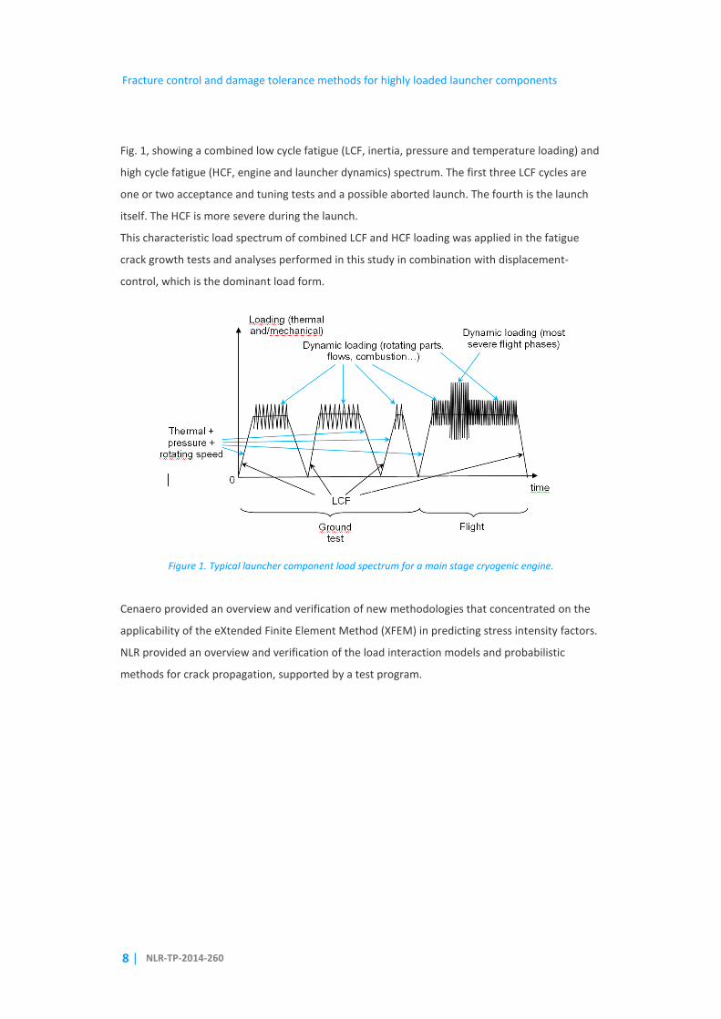
Fig. 1, showing a combined low cycle fatigue (LCF, inertia, pressure and temperature loading) and
high cycle fatigue (HCF, engine and launcher dynamics) spectrum. The first three LCF cycles are
one or two acceptance and tuning tests and a possible aborted launch. The fourth is the launch
itself. The HCF is more severe during the launch.
This characteristic load spectrum of combined LCF and HCF loading was applied in the fatigue
crack growth tests and analyses performed in this study in combination with displacement-
control, which is the dominant load form.
Figure 1. Typical launcher component load spectrum for a main stage cryogenic engine.
Cenaero provided an overview and verification of new methodologies that concentrated on the
applicability of the eXtended Finite Element Method (XFEM) in predicting stress intensity factors.
NLR provided an overview and verification of the load interaction models and probabilistic
methods for crack propagation, supported by a test program.
NLR-TP-2014-260 | 9
2 Load interaction models
Fatigue crack growth under variable amplitude loading is generally slower than under constant
amplitude loading due to retardation effects. In fatigue crack growth predictions, this effect is
included as a retardation model. These models were developed for airframe loads. For highly
loaded launcher components the overloads are much higher and other effects are also
important. Thus, different retardation models may exist that provide better crack growth
predictions than the current models do. For this reason, a literature survey was performed for
developments in the field of retardation modelling with a special focus on retardation models
that can improve crack growth predictions for highly loaded launcher components.
The models can be broadly divided into yield zone models (Wheeler, Willenborg), crack closure
models and the strip yield models. A comparison of these models shows that none of them
performs well in all cases. More recent developments are two-parameter models [1], which state
that the crack growth rate depends on Kmax and ∆K and all other effects can be attributed to
residual stresses. Plasticity induced crack closure is said to be of minor importance by these
models. A second recent development is the time-derivative model [2], which describes fatigue
crack growth as a time derivative and not as a function of a cycle. Two of the main advantages
are that it removes the need for cycle reconstruction (e.g. rain flow counting) and that it fits
better with other fundamental physical models such as the equilibrium equations and advanced
material models. A third popular approach is developed at DSTO [3], which essentially uses
variable amplitude spectrum data and a Frost-Dugdale crack propagation law to predict fatigue
crack growth under variable amplitude loading. The main advantage is that the model shows
good predictions from very small up to medium sized cracks, without using any highly complex
crack propagation and/or retardation model. For high loads in ductile materials the EPFM
approach is used. This approach replaces ΔK with ΔJ as crack propagation parameter. It can give
better results when the plastic zone size is large and then predicts faster crack growth. Finally,
full finite element analysis can be used to predict retardation but this is only computationally
feasible for academic calculations. Issues related to such FEM analyses are when to perform node
release to simulate crack advance, a rule is needed to determine how fast the crack propagates,
and how correct the plasticity model at the crack tip is.
A further issue with applying LEFM for launcher structures is that a large scale plastic cycle can
cause residual stresses. These can be determined using an elasto-plastic finite element model
and subsequently be incorporated in the crack propagation analysis. This is called plastic
shakedown in NASGRO/ESACRACK [4]. Large scale plasticity can also be added to strip yield type
Fracture control and damage tolerance methods for highly loaded launcher components
10 | NLR-TP-2014-260
of models by modifying the plastic stretches. It was experimentally observed that retardation
effects decrease for higher loads, presumably because the crack is always open.
Thermal gradients introduce additional complexities in predicting crack growth. The thermal
gradients firstly introduce residual stresses. These can be determined using a finite element
model and then be incorporated in the crack propagation analysis. Secondly, crack growth rates
depend on temperature and thus the crack propagation constant for the local temperature
should be used. Related to this is the oxidation of the crack tip causing faster crack growth at high
temperatures, depending on the time (either frequency or hold times). Finally, retardation
effects are sometimes found to be significantly smaller at high temperatures. High temperature
effects were not further studied in the current work.
2.1 Experimental results
The main questions to answer during this part of the project were whether the LEFM approach
can still be applied for crack growth after fully plastic conditions at stress levels remaining near
yield and whether significant load retardation effects are present due to load spectra consisting
of a limited number of high load cycles with HCF cycles superimposed, experienced by typical
launcher components.
The loads applied in many existing experimental data sets differs from the ones experienced by
highly loaded launcher components, where loads are experienced well above the yield limit of
the material and often under displacement control caused by the differences in thermal
expansion in launcher structures. Therefore, a limited number of load and displacement
controlled crack growth tests, with typical strain load spectra as experienced by launcher
components, were performed on material with similar quality and heat treatment as applied by
Snecma. The material used was Nickel based superalloy Inconel 718, which is a widely applied
material for engine and launcher components. Furthermore, the material availability is
reasonable and reference data is readily available in the NASGRO database against which the
current experimental results are compared.
Load controlled constant amplitude (CA) baseline spectra were applied to middle tension (MT)
specimens, without and with large scale plasticity cycle, consisting of a maximum stress of 800
MPa for R ratios: 0.2, 0.5, 0.65, and 0.8. The large scale plasticity pre-cycle up to 1.3% total strain
in spectrum was applied before the starter notch was inserted in the specimen.
NLR-TP-2014-260 | 11
Large scale plasticity displacement controlled constant amplitude or variable amplitude (VA)
spectra, including a large cycle up to 1% total strain, were applied to single edge crack tension
(SET) specimens. The VA spectra consisted of a repeated LCF cycle (representing the loading due
to the temperature profile during an engine start/stop) with a superimposed HCF random
spectrum of 1000 cycles according to a Rayleigh distribution representing a typical dynamic load
generated with ESALOAD [5]. The HCF spectrum was repeated 5 times per LCF cycle.
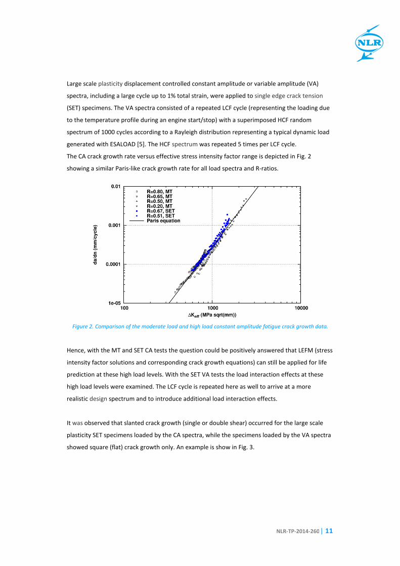
The CA crack growth rate versus effective stress intensity factor range is depicted in Fig. 2
showing a similar Paris-like crack growth rate for all load spectra and R-ratios.
Figure 2. Comparison of the moderate load and high load constant amplitude fatigue crack growth data.
Hence, with the MT and SET CA tests the question could be positively answered that LEFM (stress
intensity factor solutions and corresponding crack growth equations) can still be applied for life
prediction at these high load levels. With the SET VA tests the load interaction effects at these
high load levels were examined. The LCF cycle is repeated here as well to arrive at a more
realistic design spectrum and to introduce additional load interaction effects.
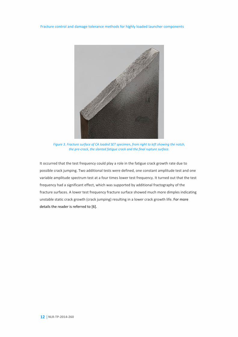
It was observed that slanted crack growth (single or double shear) occurred for the large scale
plasticity SET specimens loaded by the CA spectra, while the specimens loaded by the VA spectra
showed square (flat) crack growth only. An example is show in Fig. 3.
Fracture control and damage tolerance methods for highly loaded launcher components
12 | NLR-TP-2014-260
Figure 3. Fracture surface of CA loaded SET specimen, from right to left showing the notch,
the pre-crack, the slanted fatigue crack and the final rupture surface.
It occurred that the test frequency could play a role in the fatigue crack growth rate due to
possible crack jumping. Two additional tests were defined, one constant amplitude test and one
variable amplitude spectrum test at a four times lower test frequency. It turned out that the test
frequency had a significant effect, which was supported by additional fractography of the
fracture surfaces. A lower test frequency fracture surface showed much more dimples indicating
unstable static crack growth (crack jumping) resulting in a lower crack growth life. For more
details the reader is referred to [6].
NLR-TP-2014-260 | 13
3 Probabilistic models
Traditionally, the life of a structure is determined by means of a deterministic fracture mechanics
analysis where all the model parameters have a single value and the outcome of the analysis is
single valued as well. Either the design is rejected (“unsafe/failure”) or accepted (“safe/survival”).
In reality the life of a structure shows considerable scatter, due to initial defects, variability in
loads and material properties. The uncertainty inherent in the deterministic model is
compensated for by introducing scatter and safety factors.
These uncertainties in a crack growth analysis can be fully accounted for by means of a
probabilistic fracture mechanics analysis. Random variable models treat the uncertain model
parameters as random variables by assigning a distribution function to each of them. This is by
far the most applied method in probabilistic fracture mechanics. The most important sources of
scatter (variability) are the initial flaw size ai, the crack growth parameters C and n and the load
spectrum. Beside these, the variability in fracture toughness Kc might also be important. If a
considerable part of the load spectrum yield crack growth rates around the threshold then the
variability in the threshold stress intensity range ∆Kth might become important as well. A very
limited amount of statistical data is generally available to properly describe the various
distribution functions.
The initial flaw size, being one of the most important random variables, is very difficult or even
impossible to characterise. Some alternative strategies have been developed to circumvent these
problems, such as the so-called equivalent initial flaw size (EIFS) concept, which is based on
backward crack growth analyses of detected cracks according to a fixed master (mean) curve to
the start of the usage life, yielding a statistical dataset on which an EIFS distribution can be
determined. Issues with this approach are that the obtained initial crack sizes are not real cracks
and can be extremely small. Moreover, the obtained crack size distribution depends on the
applied crack growth model and can in principle not be transferred to other locations in the
structure (i.e. experiencing a different load spectrum or geometry) or to other components of the
same material.
The distribution functions for the crack growth parameters C and n can be determined from a
sufficiently large set of crack growth curves from identically tested specimens. Only a few of
these datasets exist. A normal distribution is appropriate to characterise the variability in both
ln(C) and m. Both parameters show a strong correlation that can be approximated by a linear
relationship.
𝑙𝑛𝐶 = 𝛼 + 𝛽𝑚 (1)
Fracture control and damage tolerance methods for highly loaded launcher components
14 | NLR-TP-2014-260
The deterministic model with assigned distribution functions to the model parameters requires
special probabilistic methods to solve. A large number of probabilistic methods have been
developed in the past decades and even recently. The most well-known and simple method is the
Monte Carlo method, but it is very inefficient especially when dealing with smaller probabilities
of failure (< 10-3), which is in general the case for engineering structures. Much more efficient
methods, such as FORM, SORM and importance sampling (IS) methods, e.g. ADIS, ARBIS, MCS_IS,
have been developed in the past decades to improve efficiency [7].
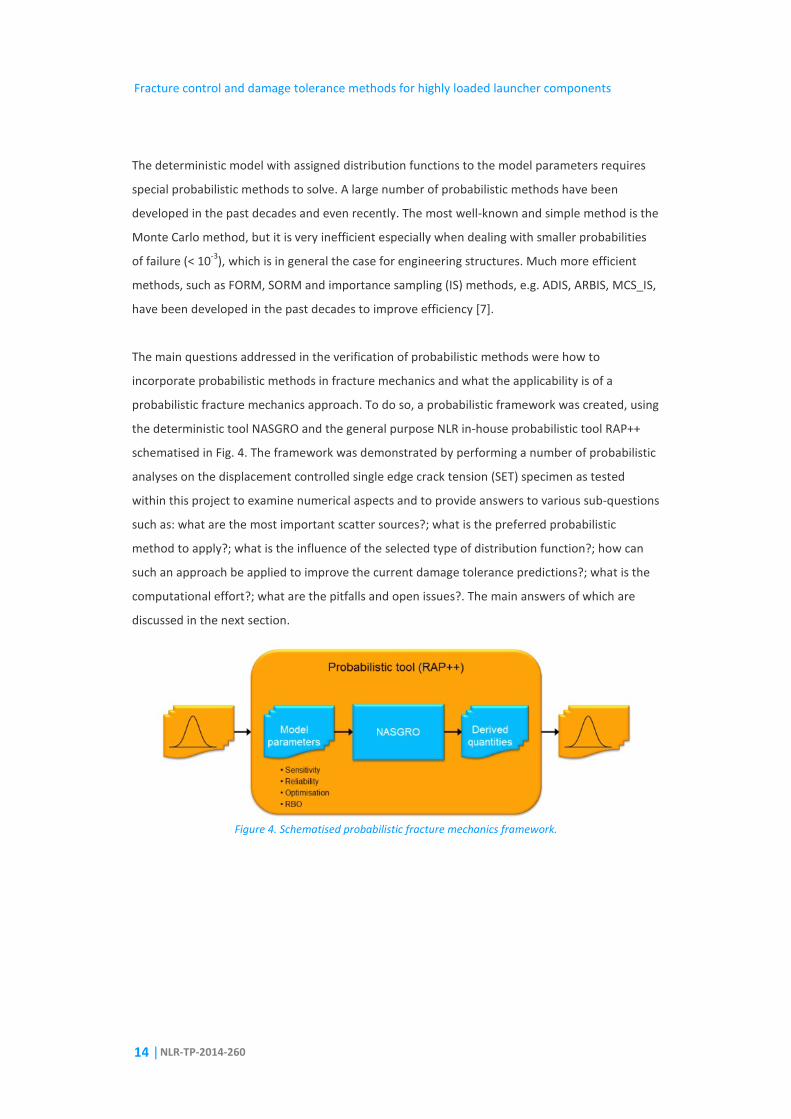
The main questions addressed in the verification of probabilistic methods were how to
incorporate probabilistic methods in fracture mechanics and what the applicability is of a
probabilistic fracture mechanics approach. To do so, a probabilistic framework was created, using
the deterministic tool NASGRO and the general purpose NLR in-house probabilistic tool RAP++
schematised in Fig. 4. The framework was demonstrated by performing a number of probabilistic
analyses on the displacement controlled single edge crack tension (SET) specimen as tested
within this project to examine numerical aspects and to provide answers to various sub-questions
such as: what are the most important scatter sources?; what is the preferred probabilistic
method to apply?; what is the influence of the selected type of distribution function?; how can
such an approach be applied to improve the current damage tolerance predictions?; what is the
computational effort?; what are the pitfalls and open issues?. The main answers of which are
discussed in the next section.
Figure 4. Schematised probabilistic fracture mechanics framework.
NLR-TP-2014-260 | 15
4 Overall synthesis and way forward
Two of the main questions to be answered in this TRP study were whether the LEFM approach
still can be applied for highly loaded launcher components, experiencing crack growth after fully
plastic conditions without global yielding afterwards, and whether load retardation effects
experienced in typical launcher component spectra can be predicted with current retardation
models. From the experimental and numerical analyses performed in the study it can be
concluded that LEFM can still be applied for highly loaded launcher components experiencing
fully plastic conditions. Due to the high loads and corresponding high R-values limited load
interaction is experienced and therefore a non-interaction crack growth model suffices,
supported by the analyses not showing significant difference between a non-interaction and load
interaction model. A conservative life estimation can therefore be obtained with
NASGRO/ESACRACK for such components.
Possible failure in the first LCF-cycle in the spectrum, causing the large scale plasticity, should be
checked independently. This is not covered by the fatigue crack growth analysis and can be done
easiest by a failure assessment diagram (FAD) analysis to check survival of the component, which
was studied in another recent ESA TRP study [8]. The current FAD procedure is based on a load-
control and does not cover displacement-control. A contract within the above TRP study has
been awarded to study extension of the FAD approach to displacement-control, regularly
experienced in highly loaded launcher components.
In general, a FAD and subsequent NASGRO/ESACRACK LEFM crack growth analysis suffice for
estimating the component life for highly loaded launcher components. The LCF temperature
cycle in launcher components can cause a displacement-controlled load contrary to a more
general load-controlled situation. Currently, only a very limited number of basic displacement-
controlled stress intensity solutions are available in NASGRO/ESACRACK. For cases for which a SIF
solution is lacking, it can be computed for various crack lengths by means of finite element or
boundary element analysis. The SIF table resulting from such analyses can easily be imported in
NASGRO/ESACRACK. Within this TRP study only finite element analyses have been examined for
this purpose since it is much more versatile and can make use of existing models of the
component. To compute the SIF, traditional crack-tip elements or the new XFEM approach can be
applied. For basic crack geometries, such as those included in NASGRO/ESACRACK, crack-tip
elements are still recommended since they provide a more stable and accurate solution. For
more complicated loads and geometries, for example turbine blades; dents; multiple cracks or
complex shaped cracks, XFEM is the only feasible approach to determine the SIF solution. Due to
the advance in FEM capability in this area over the past years, it nowadays is possible to quickly
Fracture control and damage tolerance methods for highly loaded launcher components
16 | NLR-TP-2014-260
generate the SIF solution for realistic loads and component/crack geometries, which allows a
(much) more accurate life prediction.
Generation of a number of additional displacement-controlled SIF solutions for basic geometries
is recommended to be included in NASGRO/ESACRACK to facilitate launcher design.
For both the traditional crack-tip elements and the new XFEM approach a J-integral computation
is performed from which the (mode I, II, and III) SIF solution is derived. For an elastic material the
J-integral, traversing in an anti-clockwise direction from one crack plane to the other, is equal to
the energy release rate G. It is not straightforward to compute stress intensity factors from a
known J-integral for mixed-mode problems. For instance, an interaction integral method can be
applied to compute the stress intensity factors for a crack under mixed-mode loading. A relation
between the three crack opening modes for a homogeneous, isotropic material is given by:
𝐺 = (1 − 𝜈2)�𝐾𝐼2 + 𝐾𝐼𝐼2
𝐸� + (1 + 𝜈)
𝐾𝐼𝐼𝐼2
𝐸 (2)
It can be applied to extract the individual stress intensity factors. It is also valid for an interfacial
crack between two different isotropic linear elastic materials. It is not valid for any other material
type. Currently NASGRO/ESACRACK can only handle mode I SIF solutions, which suffices in most
cases. Nevertheless, in more realistic cases with more complex geometries and loads significant
mode II and/or mode III SIFs may result, for instance the observed slanted crack growth in the
experiments performed within this program showed a combined mode I and mode III SIF
solution. Taking into account mixed mode solutions in the crack growth analysis may occasionally
improve the accuracy of the prediction, but requires an extension of NASGRO/ESACRACK.
Apart from the J-integral, the value of the so-called T-stress can be computed. This T-stress is
related to the higher-order-term of the stress equation and represents a stress parallel to the
crack faces. The sign of the T-stress determines the stability of mode-I cracking for straight crack
paths, cracks with T < 0 are stable in this mode while those with T > 0 will curve off from the
initial crack plane. Small plastic zones in actual specimens can be predicted more accurately by
including the T-stress as a second crack-tip parameter.
The J-integral in combination with the T-stress, computed from linear elastic material properties,
plays an important role in mode-I plane strain elastic-plastic crack-tip fields as well. The more
negative the T-stress becomes, the greater the reduction of hydrostatic tensile stress (triaxiality)
ahead of the crack tip. It was found that when the triaxiality is high, indicated by a positive T-
stress, the crack-tip field can be described by the so-called HRR-solution (Hutchinson, Rice and
NLR-TP-2014-260 | 17
Rosengren) and strongly depends on the J-integral. For a reduced or negative T-stress this is no
longer true. The HRR-solution plays an important role in the elastic-plastic fracture mechanics
(EPFM).
In principle the T-stress is only valid for homogeneous, isotropic linear elastic materials and is
calculated using the linear elastic material properties, but it is usually used with the J-integral
calculated using the elastic-plastic material properties of the body. The T-stress obtained from a
linear analysis can therefore be used to indicate EPFM conditions.
Related to this, it is possible to compute the J-integral in case of significant plasticity (EPFM) by
means of a non-linear finite element analysis. As indicated before, application of EPFM requires
the computation of ∆J instead of J in LEFM, which might be non-conservative in cases with
significant plasticity at the crack tip. This currently is not possible in commercial FE packages and
needs a different implementation. Since the ∆J-integral computation is a post-processing step,
this can even be done outside the finite element program.
LEFM is well founded compared to EPFM, being a simple one parameter (J-integral or SIF)
approach that is independent from the stress history (reflected by the path independency of the
J-integral), this contrary to EPFM which is path dependent. This restricts the current one
parameter EPFM approach to monotonic loading and prevents unloading or even strain
softening. Hence, crack growth is in principle not allowed since the HRR J-integral formulation is
only theoretically valid when no or little unloading occurs. It can be applied to determine crack
initiation or structural failure due to monotonically loading. Nevertheless, it can be applied to
analyse the first LCF load cycle, as an alternative to the FAD analysis.
The EPFM capability included in NASGRO/ESACRACK is limited to a few crack geometries and load
cases. No displacement-control cases are yet available. Hence, a more extensive review of
capabilities and shortcomings of the current NASGRO EPFM module is recommended. Validity of
application of EPFM in the crack growth phase, including unloading, needs to be examined.
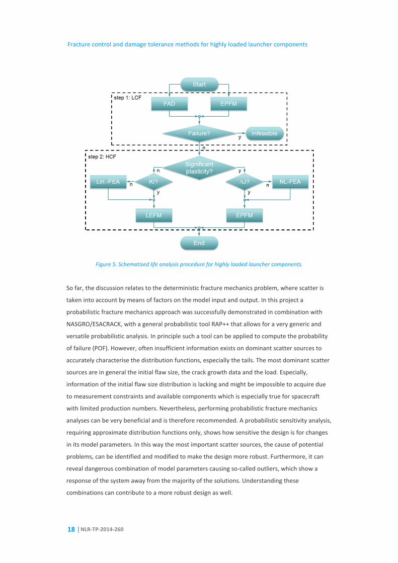
The above procedure is schematically depicted in Fig. 5, where a linear FE analysis is performed
to compute an unknown SIF solution (KI) in case of LEFM and a non-linear FE analysis to compute
an unknown ∆J solution in case of EPFM. Most of the open points related to the examples
analysed by Snecma can be solved if such a procedure is operational.
Fracture control and damage tolerance methods for highly loaded launcher components
18 | NLR-TP-2014-260
Figure 5. Schematised life analysis procedure for highly loaded launcher components.
So far, the discussion relates to the deterministic fracture mechanics problem, where scatter is
taken into account by means of factors on the model input and output. In this project a
probabilistic fracture mechanics approach was successfully demonstrated in combination with
NASGRO/ESACRACK, with a general probabilistic tool RAP++ that allows for a very generic and
versatile probabilistic analysis. In principle such a tool can be applied to compute the probability
of failure (POF). However, often insufficient information exists on dominant scatter sources to
accurately characterise the distribution functions, especially the tails. The most dominant scatter
sources are in general the initial flaw size, the crack growth data and the load. Especially,
information of the initial flaw size distribution is lacking and might be impossible to acquire due
to measurement constraints and available components which is especially true for spacecraft
with limited production numbers. Nevertheless, performing probabilistic fracture mechanics
analyses can be very beneficial and is therefore recommended. A probabilistic sensitivity analysis,
requiring approximate distribution functions only, shows how sensitive the design is for changes
in its model parameters. In this way the most important scatter sources, the cause of potential
problems, can be identified and modified to make the design more robust. Furthermore, it can
reveal dangerous combination of model parameters causing so-called outliers, which show a
response of the system away from the majority of the solutions. Understanding these
combinations can contribute to a more robust design as well.
NLR-TP-2014-260 | 19
In case insufficient data exists to accurately describe the important distribution functions,
application of probabilistic methods might be more appropriate by looking at relative
probabilities, i.e. changes in POF, for instance to examine changes in the design, materials,
operating conditions, maintenance practices and design rules.
The additional computational effort of probabilistic runs is often limited since a fracture
mechanics analysis is not computationally demanding in general.
An easy to use dedicated interface for NASGRO/ESACRACK can reduce the hurdle to perform
probabilistic fracture mechanics analyses. For more details the reader is referred to [9].
5 Acknowledgement
The research presented was funded by the European Space Agency ESA under contract
4000102474/11/NL/RA.
Fracture control and damage tolerance methods for highly loaded launcher components
20 | NLR-TP-2014-260
6 References
1. Kujawski, D., A new (∆K+Kmax)0.5 driving force parameter for crack growth in aluminum
alloys, International Journal of Fatigue, 23: 733-740, 2001.
2. Pommier, S. and M. Risbet, Time derivative equations for mode I fatigue crack growth in
metals, International Journal of Fatigue, 27: 1297-1306, 2005.
3. Molent, L., et al., Evaluation of spectrum fatigue crack growth using variable amplitude
data, International Journal of Fatigue, 30: 119-137, 2008.
4. NASGRO/ESACRACK, Fracture Mechanics and Fatigue Crack Growth Analysis Software
http://www.esacrack.com/.
5. Veul, R.P.G., Brunetti, F., Sinnema, G., Henriksen, T.K., ESALOAD User’s manual, version
4.2.2, Annex 1 of ESACRACK Manual TEC-MCS/2006/1448/In/GS Issue 4, March 2012.
http://www.esacrack.com/.
6. Huls, R.A., Grooteman, F.P. and Veul R.P.G., Fatigue crack growth in highly loaded
components, 27th ICAF Symposium, National Aerospace Laboratory, NLR-TP-2013-107,
2013.
7. Grooteman, F.P., Structural failure risk assessment, potential and pitfalls, NATO Specialist
Meeting AVT-210, National Aerospace Laboratory, NLR-TP-2013-101, 2013.
8. Structural integrity of pressurized structures, advanced non-linear methodology, ESA
Technology and Research Programme, 2012.
9. Grooteman, F.P., et al., TN10100 synthesis and guidelines reporting, National Aerospace
Laboratory, NLR-CR-2013-255, 2013.

W H A T I S N L R ?
The NL R i s a D utc h o rg an i s at io n th at i de n t i f i es , d ev e lop s a n d a p pl i es h i gh - t ech know l ed g e i n t he
aero s pac e sec tor . Th e NLR ’s ac t i v i t i es ar e soc ia l ly r e lev an t , m ar ke t-or i en ta te d , an d co n d uct ed
no t- for - p ro f i t . I n t h i s , th e NL R s erv e s to bo ls te r th e gove r nm en t ’s i n nova t iv e c apa b i l i t ie s , w h i l e
a lso p ro mo t i ng t he i n nova t iv e a n d com p et i t iv e ca pa c i t ie s o f i t s p ar tn er com pa ni e s .
The NLR, renowned for i ts leading expert ise, professional approach and independent consultancy, is
staffed by c l ient-orientated personnel who are not only highly ski l led and educated, but a lso
continuously strive to develop and improve their competencies. The NLR moreover possesses an
impressive array of high qual ity research fac i l i t ies.
NLR – Dedicated to innovation in aerospace

w w w . n l r . n l