fr. tom mcgahee’s pic controlled digital capacitance meter · accuracy the accuracy of the pic...
TRANSCRIPT

FR. TOM McGAHEE’S PIC CONTROLLEDDIGITAL CAPACITANCE METER
Design & Software Copyright July 1999Fr. Tom McGahee202 Union Ave.
Paterson, NJ 07502 USA(973)595-6655
SPECIFICATIONS
The Capacitance Meter has 4 ranges. In Manual Mode each range has an absolute minimum andmaximum reading that corresponds to a count range from 0 to 16,777,215 counts. The extremes ofeach range are where the greatest error occurs, so in the Auto Mode we restrict the range to thatportion where we will attain the greatest accuracy.
Furthermore, in the Auto Mode the count range can be seen as having five special points. Thesepoints correspond to the following:
ZERO: The absolute lowest value that can be measured. In Auto Mode this ZERO value is onlyshown on the lowest range. In Manual mode it is displayed on all ranges. When changing capacitors the unit will AutoRange to Range 1.
DOWNRANGE: This corresponds to any count lower than 4,096 in Ranges 1-3, and 32,768 inRange 4 . In Auto Mode if the count drops below this value then the meter will automatically shift to the next lowest range. If in the lowest range, then the count is displayed.
ENTRYRANGE: This corresponds to 5,242 counts on the current scale and 524,288 counts on theprevious scale. This provides some hysteresis between the value where AutoRanging enters from alower range and down-ranges back to a lower range. If this hysteresis was not present, then thecircuitry might oscillate at the point where AutoRanging kicked in.
UPRANGE: This corresponds to a count of 524,288 on the current range. In Auto Mode thecircuitry will initiate a move to the next higher range when this count is reached or exceeded. If thecurrent range is the highest range, then counting will simply continue up to the MAXCOUNTvalue.
MAXCOUNT: This correspondd to the Maximum Count value of 16,777,215 which is themaximum count value that can be attained with the 24 bit binary counters maintained by the PIC.
1

RANGES
RANGE 1: This range employs a precision 250k resistor and a divide by 100 external pre-scalerthat allows the meter to measure from 0.00 pf to .00524288 uf (5,242.88 pf) in the Auto Mode.
Note that the digits behind the decimal point will often be seen to change from reading to reading.This is partially due to the fact that the meter is responding to slight variations in the capacitor, andto stray capacitance in the leads. Coming close to the leads can cause the stray capacitance to varyby a picofarad or two. There is also the matter of a certain amount of digital error that creeps in andgets magnified due to the use of the divide by 100 prescaler. However, I have found it useful to havethe extra two digits behind the decimal point.
In Manual Mode the range is from 0.00 pf to .16777216 uf (167,772.16 pf).
RANGE 2: This range employs only a precision 250k resistor, and has an Auto Mode range from4,096 pf to .524288 microfarads (524,288 pf).
In Manual Mode the range is from 0.000000 uf to 16.777216 uf (16,777,216 pf).
RANGE 3: This range employs a trimmable resistance whose nominal value is 2.50k. I chose touse a trimmer pot to adjust the value so that the unit can be adjusted to compensate for a few sourcesof error that stem from the characteristics of the opamp I used. The Auto Mode range is from .4096uf to 52.4288 uf.
In Manual Mode the range is from 0.0000 uf to 1,677.7216 uf.
RANGE 4: This range employs the same trimmable resistance of 2.50k that was used in Range 3,and a multiply by 10 circuit that allows us to expand this range to be exactly ten times that of Range3. The times ten circuit is also trimmable so we can adjust where the circuit has maximum accuracy.In general it is useful to adjust for maximum accuracy at 100 uf. The Auto Mode range is from32.768 uf to 16,777.216 uf. Always adjust Range 3 before adjusting Range 4.
In Manual Mode the range is from 0.000 uf to 16,777.216 uf.
2
Fr. Tom McGahee’s PIC Capacitance Meter

ACCURACY
The accuracy of the PIC Capacitance Meter is influenced by several factors. The accuracy of certain resistors is critical to the accuracy of the circuit. I chose to use .1% precision resistors for the tworesistors that comprise the 250k resistance used on Range 1. I chose two .1% precision 10.0kresistors for the ratiometric comparator section, as these are crucial to the basic accuracy ofthe circuit on ALL ranges. The other resistors were chosen to be 1% metal film resistors. Trimmerpots are used to adjust the accuracy on Range 3 and Range 4.
I have used a set of precision capacitors of known value to test the accuracy of this meter, and here is what I found:
On Ranges 1 and 2 the accuracy is about .1% when run in the Auto Mode. When run in theManual Mode at counts above 1 million, the accuracy degrades to about 1%.
On Range 3 the accuracy is typically 1% when used in Auto Mode. In Manual Mode at countsabove 1 million the accuracy degrades to about 3%. Careful adjustment of the trimmer pot canresult in getting the accuracy of any desired point to be within .1%, but above and below that pointthe accuracy will decrease as the distance from that point increases.
On Range 4 the accuracy is limited by all the same factors discussed concerning Range 3. Inaddition, this range uses an opamp multiply by ten circuit. So the accuracy is also affected by theaccuracy of this multiplier and the fact that the multiplier also multiplies any noise present in thetriangle wave being fed to the comparator section. In general, don’t expect this range to give youmuch more than 1% accuracy . This can degrade to as much as 10% accuracy at the extreme highends of the range.
You might be able to increase the basic accuracy of the circuit by choosing a better operationalamplifier. I chose the TL084 because it was fairly decent, readily available, and inexpensive. Thereare some pin-for-pin compatible opamps out there that have lower input bias current and higherslew rates, and plugging one of these in may get you a bit more accuracy.
3
Fr. Tom McGahee’s PIC Capacitance Meter

Theory of Operation
Later we will show you complete schematic diagrams for the circuitry. However, to make it easierto understand the basic principles of operation I have prepared a simplified diagram of the analogsection. The analog section produces a period whose width is directly proportional to thecapacitance being measured.
The four diodes form a full-wave bridge. Across this bridge is a regular RED LED. Whenever avoltage of either polarity is applied across the 10k resistor that feeds the bridge, the voltagedeveloped at Point A will be either +3 V or -3 V. [Two diode drops plus LED diode drop]. In realitythe voltage will be slightly above or below 3 volts, but 3 volts is the value we will use in thisexplanation. So, let’s assume that the voltage at Point A is exactly +3 V. Point A connects to asimple voltage buffer (IC section D), so the output at Point B will also be +3 V. The purpose of thebuffer is to prevent loading of our reference voltage, especially at the higher ranges.
The +3 V is then applied across Rin. IC section B forms a simple integrator. The +3 V across the250k resistor will cause a current of 12 microamps to flow into Ctest, which for this example ischosen to be 1 microfarad. This causes the voltage at Point C to ramp downwards at 12 volts persecond when the reference voltage is +3 volts.
The +3 V from Point B is also connected to resistor Rb. The negative-going voltage from Point C isconnected to Ra. Since Ra and Rb are precision resistors of equal value, when Point C ramps downto -3 V, the voltage at Point D will go to zero volts. IC section C is a simple voltage comparator
4
Fr. Tom McGahee’s PIC Capacitance Meter

which compares at the zero point. As soon as the voltage at Point C goes below -3 volts the output of IC section C will switch to a large negative voltage.
This large negative voltage is applied across the 10k resistor that feeds the LED bridge, causing thereference voltage to rapidly switch to -3 volts. The voltage at Point C will now start to ramp up from -3 volts. It will continue to ramp up until it reaches +3 volts. At that moment the comparator sectionwill switch again, causing the reference to go back to being +3 volts again.
This produces a very linear +/- 3 volt triangle wave at Point C, and a clean square wave at Point E.The period of both waveforms is the same. We use the square wave output (after properconditioning) to provide the period waveform that the PIC will measure to determine capacitance.
Since during each period the triangle wave goes up a total of 6 volts and down a total of 6 volts, itexperiences a total travel of 12 volts. Since (for the present example) we know that the voltageramps at a rate of 12 volts per second, the period for the given example will be exactly one second.
The interesting thing about the circuit is that the actual voltage level that appears at Points A and Bhas literally no effect on the period that results! If the voltage was, say, 6 volts instead of the 3 weused in our example, then the voltage at Point C would be ramping up twice as fast, but it wouldhave to go twice as high or low before the comparator would trip. Thus it would take the same timeas before. The only requirement that is made on the voltage reference is that it be a stable voltageover the time the period being measured. The actual exact value of the reference doesn’t matter.Obviously, if the reference is too low or too high, that may create other problems for the opamps.The best value happens to be about +/- 3 volts. Too low, and noise in the circuit begins to dominate.Too high, and the opamps have trouble supplying enough output current near the rails.
If the use of the RED LED offends your sense of propriety, then by all means use a low voltagezener in its place. Just remember that there are two diode drops due to the use of the bridge, so youwant to choose a low voltage zener such as 2.5 volts.
5
Fr. Tom McGahee’s PIC Capacitance Meter

THE FULL ANALOG CIRCUIT
When you look at the full schematic of the analog section above, you will see that I have added anLF356 opamp to produce a decent pseudo ground for the quad opamp. This allows us to run thequad opamp with a single 12 volt supply. As far as the quad opamp is concerned, it sees +/- 6 voltsas its supply voltages. Keep this in mind if you decide to go snooping around with an oscilloscopeor voltmeter. Expect to see an offset of about +6 volts with respect to the digital ground.
A trimmer pot is used to fine adjust the actual offset voltage. This allows us to adjust the offset suchthat the symmetry of the +/- 3 volt reference is preserved. This helps us to get a bit more resolutionout of the circuit. The 100 uf capacitor shown connected between the pseudo ground and the systemdigital ground is there to improve the response of the analog ground and reduce systems noise.
Relay A is used to control the value of Rin. This allows us to switch between Ranges 1-2 andRanges 3-4. Relay B is used to switch Section A of the quad opamp between a gain of 1 and a gain of 10. The gain of 10 makes it possible to reduce by a factor of ten the time it takes to obtain a givencount. Without this feature the upper limit would have been about 1,000 ufd. With this addition wecan go out to over 16,000 ufd, though we do lose some accuracy in the process. I used relays herebecause any additional circuit resistance would have affected overall accuracy. CMOS switchescreate too much error in this particular application.
The 74HC390 is arranged so that it provides a symmetrical divide by 100 function. The 4011 IC iswired up as a simple Data Selector. The PIC can control whether it is selecting the Period or the
6
Fr. Tom McGahee’s PIC Capacitance Meter

Period multiplied by a factor of 100. This is used to increase the accuracy of the lowest range so thatwe can accurately measure down to the picofarad level.
A 555 timer circuit is connected up as a negative voltage generator in case the LCD you are usingrequires a negative bias. If your LCD works with the bias line grounded, then you can leave out allthe parts associated with the negative voltage generator. In that case, connect the bias line of theLCD to a ground point on the pc board.
THE PIC PART
The PIC 16F84 provides the control functions that determine the Range, and it also provides thelogic for implementing AutoRanging. The PIC internally counts the number of 1 microsecondinstruction cycles that occur during a given Period. The PIC then subtracts an offset value from thebinary count and uses this to help eliminate many of the sources of error that would otherwisereduce the accuracy of the circuit.
The offset that is subtracted can be either the intitial stray capacitance for each of the four scales that is determined when the unit is first turned on, or it can be a value that was in effect when the ManualMode is entered.
THE LCD PART
The PIC takes the binary information and uses that and the Range information to format thenumbers displayed on the LCD.
The LCD display that I used is one that displays two rows with 16 characters per row. The top rowdisplays the numerical part of the measurement. The number displayed will include a comma if thevalue exceeds 1,000 units. Leading zeros are suppressed up to the decimal point.
Digits after the decimal point may include trailing underscores to indicate non-implemented digitlocations.
Various markers are displayed to show the state of the machine, and error messages are displayedwhen appropriate.
A + or - in the first position of the first line is used to indicate whether the currently displayed valueis larger or smaller than the reference value. The reference value is initially set to zero, but the usermay choose to lock in any current value as a reference value. For example, if you have a reading of 1.2345 uf and you press the ZERO button, then the display goes to zero and the Manual Mode isentered. If you now remove the capacitor, then you will see a reading of -1.2345 uf displayed. Put a1.0000 uf capacitor on, and the reading goes to -.2345. Put a 2.0000 uf capacitor on, and the readingwill change to +.7655 uf. This is a feature not found on other capacitance meters.
Sometimes you will see the letter “M” displayed in the second position of the first line. It willusually appear to be blinking. It’s purpose is to warn the user that the currently displayed value is
7
Fr. Tom McGahee’s PIC Capacitance Meter

outside the usual limits used on that Range in the Auto Mode. We flag this condition because theaccuracy of the meter falls off when you get outside the suggested range limits.
In the first position of the second line there will be a number from 1 to 4 displayed. This numbercorresponds to the currently selected Range.
Following the range number will be the value designators, such as uf nf pf. These are arranged sothat they line up immediately below the corresponding numerical digits on line one. I chose todisplay more than one value designator at a time, because sometimes I want to know the value inmicrofarads, and at other times I may want to know it in nanofarads or picofarads. This arrangement also allowed me to get by with just 4 ranges. Ranges 1 and 2 share a common display arrangement,as do Ranges 3 and 4.
The last three positions on the second line are used for special markers. Position 13 will bedisplaying an “A” if the unit is in Auto Mode, or an “M” if the unit is in Manual Mode. Positions 14and 15 are used to display the current “state” of the meter. When the unit has achievedsynchronization and is waiting for the count to be accumulated, a black box will move back andforth. When a new count has been displayed “**” will be displayed as well.
Whenever you begin to measure a new capacitor, wait until you have seen the unit go through thiscycle of moving black box and ** at least two times to insure that you are getting a valid reading.
Whenever the unit AutoRanges it will display a message to that effect. This is to warn you to wait asecond or two so you get a stable reading. If a count exceeds the 24 bit binary limit of 16,777,216then an OVER-RANGE message will be displayed.
In the Manual Mode if you go out of range then the error message becomes MANUALOVER-RANGE to remind you that you are in Manual Mode.
THE PUSHBUTTONS
Several pushbuttons are available to allow Reset, UpRange, DownRange, and Zero. Because thepresence of a pushbutton closure is only tested for at certain points in the program, it is best if youhold the button depressed until you see that the activity marker stops. The button will be respondedto when you release the button. If you just take a quick stab at the pushbutton it may not be detected.
RESET performs the same function as turning the power on. A new set of auto-zero values areaccumulated for each range, and Auto Mode is entered. It is important that you remove anycapacitor before doing a reset. Otherwise the unit will valiantly attempt to use the current capacitorvalue as the auto-zero value. If the capacitor value is large then you may start to get over-range error messages on the lower ranges, and the unit may get “hung up”.
UPRANGE causes the meter to enter the Manual Mode and move to the next higher range. Oncethe highest range is reached, the meter stays at that range.
8
Fr. Tom McGahee’s PIC Capacitance Meter
DOWNRANGE causes the meter to enter the Manual Mode and move to the next lower range.Once the lowest range is reached, the meter stays at that range.
ZERO causes the meter to enter the Manual Mode and sets the meter to read zero at the currentrange. This is useful not only for zeroing out stray capacitance, but also for subtracting the entirecurrent capacitance value from displayed reading.
A + is displayed whenever the current capacitor value is greater than the zero value, and a - isdisplayed whenever the current capacitor value is lower than the zero value. This is extremelyuseful for comparing two capacitors, or for watching the changes that are occuring in a givencapacitor
SOME ENLIGHTENING EXPERIMENTS.
Try this interesting experiment:
Turn the unit on with no capacitor OR leads attached. The unit will come up in Range 1. Wait a fewseconds and write down the displayed value, which is typically less than .2 pf. Now add a set of clipleads to the terminals. Twist the leads slowly together while you watch the display. You will findthat the lead capacitance will amount to several picofarads, perhaps going as high is 30 pf. If youtouch one of the leads directly, or even if you just handle the insulation, you will see that your bodyhas a capacitance that amounts to several pf.
Another enlightening experiment:
Connect an electrolytic capacitor having a value of about 1,000 uf and wait about a minute so thecapacitor value has a chance to stabilize. Then push the ZERO pushbutton for a second or two.When you release it the display should go to zero within a few seconds. (You may have disturbedthe unit in the middle of a count sequence, and it will begin a new full conversion sequence to insure it gets the proper “zero” value).
Once you get the zero reference reading, note that the count varies a bit from reading to reading.This is NOT due to error, as you will soon see! Grab the electrolytic capacitor tightly so that yourbody heat begins to heat the capacitor up. As you warm it up with your body heat you will see that itwill vary its capacitance by several microfarads. I can usually get a change of about 20 uf just usingbody heat! Hopefully this will explain to you why the unit will measure 1,000 uf today and 1,100 uftomorrow when it has been sitting in the sun. This experiment also shows you why electrolyticcapacitor values are usually given tolerances like +80 -20 %.
You now know that you have to exercise care when measuring very small AND very large values ofcapacitance.Guess what? You have to be careful when measuring ANY size capacitor! CapacitorsDO change their values based on temperature and other factors.
The unit is very useful in comparing different TYPES of capacitors so that you will know how theyrespond to environmental factors.
9
Fr. Tom McGahee’s PIC Capacitance Meter
CALIBRATION OF THE PIC CAP METERADJUST LCD BIAS
Turn the unit on and adjust the negative bias 10k trimpot for the best looking display on the LCD.This is the trimpot shown on the left, nearest to the 555 timer. If using an LCD that does not requirea negative bias voltage, ensure that the bias input line (pin 3) from the LCD is connected to ground.There is a ground point connection pad available for this purpose at the extreme left of the analogpc board, just below and to the left of the 10 uf capacitor.
SAFETY PRECAUTIONS
Before attaching any capacitor, always short the leads out first! It is normal for acapacitor to have a residual charge, so ALWAYS be safe and short out thecapacitor before attaching it to the binding posts.
The TL084 Quad OpAmp may be damaged if you accidentally apply more than ten volts. The unititself will normally not apply a voltage in excess of +/- 3 volts, so it may be safely used to measureelectrolytic and other polarized capacitors. Binding posts are not polarized, and capacitors may beconnected up either way.
ADJUST PSEUDO GROUND SYMMETRY
Place the unit into Manual Mode and switch to Range 3 by using the UPRANGE pushbutton. Thecurrent Range is displayed as a number from 1-4 at the beginning of the second line. Attach a 10 ufcapacitor to the binding posts. Adjust the pseudo ground symmetry 10k trimpot located at the rightside of the board, just above the LF356 IC. Look at the RED LED at the upper right hand side of theanalog pc board. Adjust the trimpot so that the brightness of the RED LED is constant. Thisadjustment ensures that the voltage of the reference source is equal for both polarities. Thisadjustment will normally leave the trimpot near its midpoint. The reason for using a 10 ufd onRange 3 is that with this value and range combination the output of the comparator will have afrequency of about 10 Hz. The human eye can easily discern any current mismatch as a visualflickering. The flicker is hard to discern when the period is too short, and difficult to compare whenthe period is too long.
CALIBRATE RANGE 1
Range 1 requires no calibration, as it uses .1% precision resistors to ensure an accuracy of betterthan 1%. The 74HC390 divider section introduces no appreciable error.
10
Fr. Tom McGahee’s PIC Capacitance Meter

CALIBRATE RANGE 2
Range 2 requires no calibration, as it also uses the same .1% precision resistors to ensure anaccuracy of better than 1%.
CALIBRATE RANGE 3
Range 3 requires that the leftmost 1k ten turn trimpot be adjusted near the center of its range. Youcan make use of the fact that Range 2 and Range 3 overlap. Use the UPRANGE andDOWNRANGE pushbuttons to get into Manual mode and on Range 2, which is already calibrated.ZERO the display. Attach a capacitor having a value between .4 uf and 3 uf. Write down thecapacitor value displayed. Use the UPRANGE pushbutton to move to Range 3. Adjust the Leftmost 1k ten turn trimpot such that the reading coincides with the value you wrote down. You may want togo back and forth between Range 2 and Range 3 a couple of times to verify that the displayed values coincide within 1%.
CALIBRATE RANGE 4
Range 4 relies heavily on the calibration of Range 3. Anytime you calibrate Range 3, you shouldthen re-calibrate Range 4. In addition to relying on the calibration of Range 3, Range 4 uses aprecision multiply by ten circuit. You can adjust the exact multiplication value by adjusting therightmost 1k ten turn trimpot. Calibrate by using a capacitor with a value of about 100 uf. Place theunit on Range 3 and write down the displayed value. Switch to Range 4 and adjust the rightmost 1kten turn trimpot until the displayed value is as close to the value you wrote down as you can get. You may want to go back and forth between Range 3 and Range 4 a couple of times to verify that thedisplayed values coincide within 1%.
System is now calibrated.
11
Fr. Tom McGahee’s PIC Capacitance Meter

BITS AND PIECESThe remaining pages contain the parts list, schematics, parts placement diagrams, and pc boardlayouts. Note that I have built my unit using two separate pc boards. I piggy-backed these twoboards so that I could fit the whole unit into a reasonable sized case. I piggy-backed them in such away that the foil sides faced one another with a separation of about 1/2 of an inch. This allowed meto easily get at the components on both boards. I recommend that you have the analog board facingaway from the front panel. This allows you to easily get at the calibration adjustment controls,especially the pseudo ground symmetry control.
The diagrams are given at 100% scale so that you can use them to directly produce the pc boards.The parts placement diagram shows all parts, jumpers, and interconnecting wires. I have shown theparts from the top view, and you will notice that a light gray is used to indicate the underlyingprinted circuit board traces.
The two 1k ten turn pc board pots that adjust the ranges can be either the long skinny type, or thelittle square types. The pc board pattern has been designed so that it will accomodate either style.
I purchased all my parts from:
MOUSER Electronics1-(800)346-6873http://www.mouser.com
The only parts not purchased from MOUSER were the PIC 16F84, which I got from:
DIGI-KEY1-(800)344-4539http://www.digikey.com
and the 16x2 LCD, which I liberated from a piece of industrial equipment. These are available frommany sources, including DIGI-KEY.
12
Fr. Tom McGahee’s PIC Capacitance Meter
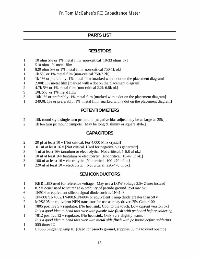
PARTS LIST
RESISTORS
1 10 ohm 5% or 1% metal film [non-critical 10-33 ohms ok]1 510 ohm 1% metal film1 820 ohm 5% or 1% metal film [non-critical 750-1k ok]1 1k 5% or 1% metal film [non-critical 750-2.2k]1 1k 1% or preferably .1% metal film [marked with a dot on the placement diagram]1 2.00k 1% metal film [marked with a dot on the placement diagram]2 4.7k 5% or 1% metal film [non-critical 2.2k-6.8k ok]9 10k 5% or 1% metal film 3 10k 1% or preferably .1% metal film [marked with a dot on the placement diagram]1 249.0k 1% or preferably .1% metal film [marked with a dot on the placement diagram]
POTENTIOMETERS
2 10k round style single turn pc mount [negative bias adjust may be as large as 25k]2 1k ten turn pc mount trimpots. [May be long & skinny or square style.]
CAPACITORS
2 20 pf at least 10 v [Not critical. For 4.000 Mhz crystal]1 .01 uf at least 16 v [Not critical. Used for negative bias generator]3 1 uf at least 16v tantulum or electrolytic. [Not crititcal. 1-6.8 uf ok.]1 10 uf at least 16v tantulum or electrolytic. [Not critical. 10-47 uf ok.]3 100 uf at least 16 v electrolytic. [Not critical. 100-470 uf ok]1 220 uf at least 10 v electrolytic. [Not critical. 220-470 uf ok]
SEMICONDUCTORS
1 RED LED used for reference voltage. [May use a LOW voltage 2.5v Zener instead]1 8.2 v Zener used to set range & stability of pseudo ground. 250 mw ok.6 1N914 or equivalent silicon signal diode such as 1N41486 1N4001/1N4002/1N4003/1N4004 or equivalent 1 amp diode greater than 50 v2 MPSA05 or equivalent NPN transistor for use as relay driver. 25v Gain>1001 7805 positive 5 v regulator. [No heat sink. Cool to the touch. Low current version ok]
It is a good idea to bend this over with plastic side flush with pc board before soldering.1 7812 positive 12 v regulator. [No heat sink. Only very slightly warm.]
It is a good idea to bend this over with metal side flush with pc board before soldering.1 555 timer IC1 LF356 Single OpAmp IC [Used for pseudo ground, supplies 30 ma to quad opamp]
13
Fr. Tom McGahee’s PIC Capacitance Meter

1 TL084 Quad OpAmp IC [substitute only with BETTER slew rate and input current]MOUSER # 511-TL084ACN $1.10 or 511-TL084IN $0.74 14 pin DIP
1 4011 Quad 2 Input NAND CMOS IC MOUSER # 511-4011 $0.391 74HC390 Dual Decade Counter CMOS IC MOUSER # 511-M74HC390 $0.671 PIC 16F84 Microchip Microcontroller (Must be programmed with CMETERA.ASM)
OTHER
1 Set of Single Sided Printed Circuit Boards. Homemade. Press N Peel works well.2 12v @ 30 ma SPDT with 1 amp contactsubminiature relays MOUSER part # 431-16121 16x2 LCD Display such as those by OPTRONIX (Hitachi Controller)
Mine used a 14 pin header organized as 2x7. Some models have a 1x14 organization.If you use the 1x14 style LCD, then you can just solder the wires directly to the digitalpc board. Odd numbers are towards the PIC. Pins 1 and 14 are marked on the PartsPlacement Diagram. Ignore the triangle symbol. That is just there to indicate the properheader orientation. Since the headers at the LCD are mirrored instead of normal, we hadto mirror our pc header also. Before soldering wires direct to the pc board, just insurethat pin 1 goes to pin 1, etc. See further discussion below...
1 4.000 Mhz Crystal1 14 pin header to connect to LCD cable. Mounts on component side. Stripe of cable
goes on side marked with number 1.1 14 pin cable to connect LCD to PIC board (5” or more, Female connectors on both ends)
If using 2x7 header, just plug in with stripe oriented on same side as pin 1. If using1x14 style LCD, you can leave off the header and solder direct if desired. But be carefulif you decide to mix the pcb 2x7 and an LCD that is 1x14. The IDC cable pins are usuallynumbered *1 2 3 4 etc., but due to the mirrored wiring used on 2x7 LCD displays,the cable coming from the pcb will actually be *2 1 4 3 6 5 8 7 10 9 12 11 14 13, wherethe * indicates the striped wire. Yeah, it can be confusing, so be very careful!
X Sockets for each IC (Optional)4 SPST Normally Open Pushbutton Switches (el cheapo variety ok)1 On/Off Switch (I used a push on / push off style)1 Power Indicator LED and current limiting resistor (Optional. Steal power from +12v)2 Binding Posts. (I used two white ones, as the terminals are NOT polarized)1 Case. I used the MOUSER # 546-1595E-BU Sloped Case
Measurements were 8.5” x 5.1” x 1.85” with rise to 2.9” at the back. $12.451 12 VAC Wall Power Cube rated for at least 100 ma. [May be DC style also. 18 V max]
Miscellaneous nuts, bolts, screws, wire, etc.
Make sure you install all jumpers shown on the Parts Placement Diagram!
I used a thin sheet of plexiglass (perspex) between the cutout for the LCD and the actual displayscreen, so that the LCD display is protected.
14
Fr. Tom McGahee’s PIC Capacitance Meter

Some Comments by the Author
The original diagrams were prepared using AutoCad version 12, and are based on customschematic symbols that I prepared myself. These diagrams were then converted to PDF formatusing Adobe Acrobat version 4.0. Diagrams that would need to be re-sized and included on thesame pages as regular text were then exported from Adobe Acrobat in Postscript format. ThesePostscript files were found to be the highest quality way to import the original AutoCad files intothe desktop publishing program that I used.
The typesetting and layout work was done using Corel Ventura Desktop Publisher version 8. Whenall this was done, the final document sections were converted to PDF format. The assembly listingwas done using Courier monospaced font in simple text format so that it can be directly used withinMPLAB.
Adobe Acrobat was chosen as the final medium for presentation because of the widespreadavailability of the free Adobe Acrobat Reader software on many different platforms. AdobeAcrobat allows the user to print high quality copies. All artwork was prepared and saved at 600 dpi.
CMETER.PDF is this document, which contains the main text and two drawings. PCB.PDF is the printed circuit board layouts for both boards.PARTS.PDF is the parts placement diagram for both pc boards.SCHANA.PDF is the large schematic for the Analog section.SCHDIG.PDF is the large schematic for the Digital section.CMETERA.ASM is the assembler file.
[CMETER.DWG is the Autocad file containing all the original drawings.]
The assembler file may be directly used under Microchip’s MPLAB software to prepare thenecessary HEX file required to program a PIC 16F84. The user should change the two messagelines that appear when the unit is powered-up or reset. These lines currently say “PIC CAPMETER”, and “Fr Tom McGahee”. Maximum line length is 16 characters.
I hope that even if you don’t build one of these Capacitance Meters you will still have learnedsomething from looking over these documents.
Feel free to share the plans with others. If you would like to post the plans on your web site, youhave my permission to do so.
While I am making these plans freely available for hobbiests and professionals, I do want tomaintain control and ownership of the designs. So, if you do distribute these documents, distributethem in their entirety. If you want to make changes, feel free to do so. In that case you might want tomake a set of addendums to the original documentation.
Let me know if you found the plans useful. My e-mail address is on the first page.
15
Fr. Tom McGahee’s PIC Capacitance Meter

0 1 2 3 4 5 6 7 8 9 10 11 12 13 14 15
+/- (M)
u f n f p fMA
* *
RANGE 1
[pselect = 1] .00_ pf to .005 242 88_ uf (.5 second)
Never Shifts Down. Shifts Up at 524,288 ( 2^19)
RANGE 2
[All Off] 4,096 pf to .524 288 uf (.5 second)
Shifts Down at 4,096 (2^12) Shifts in Low at 5,242
Shifts in High at 409,600 Shifts Up at 524,288 (2^19)
0 1 2 3 4 5 6 7 8 9 10 11 12 13 14 15
+/- (M)
u f n fMA
* *
RANGE 3[Controla = 1] .409 6__uf to 52.428 8__ uf (.5 second)
Shift Down at 4,096 (2^12) Shifts in Low at 5,242
Shifts in High at 409,600 Shifts Up at 524,288 (2^19)
RANGE 4
[Controla+controlb = 1] 32.768 uf to 16,777.216 uf (17 seconds)
Shift Down at 32,768 (2^15) NEVER Shift Up: OVERFLOW past 16,777.216 ufd
16
Fr. Tom McGahee’s PIC Capacitance Meter
TABLE SHOWING DISPLAY FORMAT ANDRANGE INFORMATION