fps2000
TRANSCRIPT

© 2000 Cambridge SoundWorks, Inc.
FourPointSurround™ FPS2000 DigitalMultimedia Speaker System
Installation and Operating Instructions
FPS2000 Rev.C 4/17/00, 4:09 PM1

i
Notice for the USAFCC Part 15: This equipment has been testedand found to comply with the limits for a Class Bdigital device, pursuant to Part 15 of the FCCRules. These limits are designed to providereasonable protection against harmful interferencein a residential installation. This equipmentgenerates, uses, and can radiate radio frequencyenergy and, if not installed and used inaccordance with the instructions, may causeharmful interference to radio communications.However, this notice is not a guarantee thatinterference will not occur in a particularinstallation. If this equipment does cause harmfulinterference to radio or television reception, whichcan be determined by turning the equipment offand on, the user is encouraged to try one or moreof the following measures:
❑ Reorient or relocate the receiving antenna.
❑ Increase the distance between theequipment and receiver.
❑ Connect the equipment to an outlet on acircuit different from that to which thereceiver is connected.
❑ Consult the dealer or an experiencedradio/ TV technician.
CAUTION: To comply with the limits for the ClassB digital device, pursuant to Part 15 of the FCCRules, this device must be installed with computerequipment certified to comply with the Class Blimits.
All cables used to connect the computer andperipherals must be shielded and grounded.Operation with non- certified computers or non-shielded cables may result in interference to radioor television reception.
ModificationsAny changes or modifications not expresslyapproved by the grantee of this device could voidthe user’s authority to operate the device.
Notice for CanadaThis apparatus complies with the Class B limits forradio interference as specified in the CanadianDepartment of Communications Radio InterferenceRegulations.
Cet appareil est conforme aux normes de CLASSE“B” d’interference radio tel que spe’cifie’ par leMinistère Canadien des Communications dans lesrèglements d’interfèrence radio.
Safety & Regulatory InformationThe following sections contain notices for various countries:
Declaration of ConformityAccording to the FCC96 208 and ET95- 19
Manufacturer/Importer’s Name: Creative Labs Inc.
Manufacturer/Importer’s Address: 1901 McCarthy Boulevard
Milpitas, CA. 95035United States
Tel: (408) 428-6600
declares under its sole responsibility that theproduct
Trade Name: Creative Labs/Cambridge SoundWorks
Model Number: CSW1500
has been tested according to the FCC / CISPR22/85requirement for Class B devices and foundcompliant with the following standards:
EMI/ EMC: ANSI C63.4 1992, FCC Part 15Subpart B
This device complies with part 15 of the FCC Rules.Operation is subject to the following twoconditions:
1. This device may not cause harmful interference,and
2. This device must accept any interferencereceived, including interference that may causeundesirable operation.
Ce matériel est conforme à la section 15 des réglesFCC. Son fonctionnement est soumis aux deuxconditions suivantes:
1. Le matériel ne peut étre source d’interférenceset
2. Doit accepter toutes les interférences reques, Ycompris celles pouvant provoquer unfonctionnement indésirable.
Compliance ManagerCreative Labs, Inc.January 18, 1999
ComplianceThis product conforms to the following CouncilDirective:
❑ Directive 89/ 336/ EEC, 92/ 31/ EEC (EMC),73/23/EEC (LVD)
ModificationsAny changes or modifications not expresslyapproved by the grantee of this device could voidthe user’s authority to operate the device.
WARNING: To preventfire or shock hazard, donot expose this applianceto rain or moisture.
Important NoticeThe serial number for the FPS2000 Digital islocated on the subwoofer. Please write thisnumber down and keep it in a secure area. This isfor your security.CAUTION:
This symbol indicates that the marked item may be hot and should not be touchedwithout taking care.
• To minimize the risk of burns or other injuries to children, position the devicesuch that hot surfaces are out of their reach.
• To minimize the risk of fire, keep flammable materials like paper and cloth (forexample, curtains) away from the hot surfaces.
FPS2000 Rev.C 4/17/00, 4:09 PM2

ii
VENTILATION - Slots and openings in thecabinet are provided for ventilation and toensure reliable operation of the subwooferand to prevent it from overheating. Theseopenings must not be blocked or covered.The openings should never be blocked byplacing the product on a bed, sofa, rug, orother similar surface. The openings shouldnot be placed in a built-in installation suchas a bookcase or rack unless proper ven-ti lation is provided or CambridgeSoundWorks’ instructions have been ad-hered to.
HEAT - The subwoofer should be situatedaway from heat sources such as radia-tors, heat registers, stoves, and otherproducts (including amplifiers) that pro-duce heat.
POWER SOURCES - The subwoofer shouldbe operated only from the type of powersource indicated on the marking label. Ifyou are not sure of the type of powersupply to your home, consult your productdealer or local power company. For prod-ucts intended to operate from batterypower, or other sources, refer to the oper-ating instructions.
POLARIZATION - The power supply may beequipped with a polarized alternating-cur-rent line plug (a plug having one bladewider than the other). This plug will fit intothe power outlet only one way. This is asafety feature. If you are unable to insertthe plug fully into the outlet, try reversingthe plug. If the plug should still fail to fit,
contact your electrician to replace yourobsolete outlet. Do not defeat the safetypurpose of the polarized plug.
POWER-CORD PROTECTION - Power sup-ply cords should be routed so that they arenot likely to be walked on or pinched byitems placed upon or against them, payingparticular attention to cords at plugs, con-venience receptacles, and the point wherethey exit from the subwoofer.
LIGHTNING - For added protection for theFPS2000 Digital system during a lightningstorm, or when it is left unattended andunused for long periods of time, unplug itfrom the wall outlet. This will prevent dam-age to the subwoofer due to lightning andpower-line surges.
OVERLOADING - Do not overload wall out-lets, extension cords, or integral conve-nience receptacles as this can result in arisk of fire or electric shock.
OBJECT AND LIQUID ENTRY - Never pushobjects of any kind into the subwooferthrough openings as they may touch dan-gerous voltage points or short out partsthat could result in a fire or electric shock.Never spill liquid of any kind on the speak-ers or the subwoofer.
SERVICING - Do not attempt to service anypart of the FPS2000 Digital yourself asopening or removing covers may exposeyou to dangerous voltage or other haz-ards. Refer all servicing to qualified ser-vice personnel.
DAMAGE REQUIRING SERVICE - Unplugthe power supply from the wall outlet orother power source and refer servicing toqualified service personnel under the fol-lowing conditions:a) When the power supply adapter or plugis damaged.b) If liquid has been spilled, or objectshave fallen into the subwoofer.c) If the subwoofer or power supply adapterhas been exposed to rain or water.d) If the FPS2000 Digital does not operatenormally by following the operating in-structions; or exhibits a distinct change inperformance.e) If the product has been dropped ordamaged in any way.
REPLACEMENT PARTS - When replace-ment parts are required, be sure the ser-vice technician has used replacementparts specified by Cambridge SoundWorksor have the same characteristics as theoriginal parts. Unauthorized substitutionsmay result in fire, electric shock, or otherhazards.
SAFETY CHECK - Upon completion of anyservice or repairs to the FPS2000 Digitalsystem, ask the service technician to per-form safety checks to determine that theFPS2000 Digital system is in proper op-erating condition.
WALL OR CEILING MOUNTING - TheFPS2000 Digital satellites should bemounted to a wall or ceiling only as rec-ommended by Cambridge SoundWorks.
IMPORTANT SAFETY INSTRUCTIONSREAD INSTRUCTIONS - All safety and oper-
ating instructions should be read before theFPS2000 Digital amplified subwoofer/sat-ellite system is operated.
RETAIN INSTRUCTIONS - The safety andoperating instructions should be retainedfor future reference.
HEED WARNINGS - All warnings on thesubwoofer and in the operating instruc-tions should be adhered to.
FOLLOW INSTRUCTIONS - All operatingand use instructions should be followed.
CLEANING - Unplug the Power SupplyAdapter from the wall outlet or other powersource before cleaning. Do not use liquidcleaners or aerosol cleaners. Use a dampcloth for cleaning.
ATTACHMENTS - Do not use attachmentsnot recommended by CambridgeSoundWorks as they may cause hazards.
WATER AND MOISTURE - Do not use thesubwoofer near water—for example, neara bath tub, wash bowl, kitchen sink, orlaundry tub; in a wet basement; or near aswimming pool; and the like.
ACCESSORIES - Do not place the FPS2000Digital system on an unstable cart, stand,tripod, bracket, or table. The subwoofermay fall, causing serious injury to a childor adult, and serious damage to the prod-uct. Any mounting of the satellites or sub-woofer should follow the manufacturer’sinstructions, and should use a mountingaccessory recommended by CambridgeSoundWorks.
FPS2000 Rev.C 4/17/00, 4:09 PM3

iii
Introduction ................................................................................................ 1Inspecting For Damage ................................................................................ 2Overview ..................................................................................................... 2Installation Sequence .................................................................................. 2Speaker Placement ...................................................................................... 3Speaker Wiring Diagram ............................................................................. 4Satellite Connections ................................................................................... 5Attaching The Floor Stands ......................................................................... 6Power Supply Adapter ................................................................................. 7Audio Signal Connections ........................................................................... 7Connection To Sound Blaster Live! Via DIGITAL DIN .................................. 8Volume Control ............................................................................................ 8Using The Volume Control ........................................................................... 9Mounting The Volume Control .................................................................... 9Adjusting Output Level ............................................................................. 10Bass Level Control ..................................................................................... 10Optimizing The Sound Of Your System ..................................................... 11Mounting The Satellites ............................................................................ 11Important .................................................................................................. 12Specifications ............................................................................................ 12Technical Support ..................................................................................... 121-Year Limited Warranty ........................................................................... 13
ContentsFourPointSurround
FPS2000 DigitalMultimedia Speaker System
FPS2000 Rev.C 4/17/00, 4:09 PM4
1
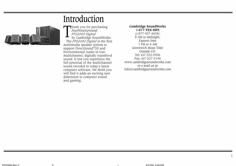
hank you for purchasingFourPointSurroundFPS2000 Digitalby Cambridge SoundWorks.T
The FPS2000 Digital is the firstmultimedia speaker system tosupport DirectSound®3D andEnvironmental Audio in truemultichannel, digitally transferedsound. It lets you experience thefull potential of the multichannelsound encoded in today’s latestcomputer software. We think youwill find it adds an exciting newdimension to computer soundand gaming.
IntroductionCambridge SoundWorks
1-877-YES-HIFI(1-877-937-4434),8 AM to Midnight,
Eastern time1 PM to 4 AM
Greenwich Mean TimeOutside US:
Tel: 617-332-5936Fax: 617-527-3194
www.cambridgesoundworks.comor e-mail us at
FPS2000 Rev.C 4/17/00, 4:09 PM5

2
Installation SequenceInspectingFor DamageExamine each speaker unit carefullyfor signs of shipping damage. If thereis any damage, do not install thesystem.
If there is any problem, or ifanything is missing, call the storewhere the system was purchasedor refer to the “Technical Support”section on pages 12-13.
Save the carton and its inserts incase you need to transport yourFPS2000 Digital system later.
1. Read through the instructionsbefore installing the speakers.The instructions assume you havea 4-channel sound card–one thatsupports DirectSound®3D andhas separate front and rear stereominijack outputs. If your soundcard has a single stereo minijackline output, please read the noteunder “Audio SignalConnections” on page 7.
2. Place the satellites and the sub-woofer at appropriate sites nearyour computer. Attach the stands,if necessary.
3. To help you identify eachsatellite’s channel, apply theappropriate preprinted label tothe rear of each satellite.
4. Connect the four satellites to theback of the subwoofer enclosure.Leave all the wires accessible.
5. Connect your sound cardoutputs to the subwoofer.
The four small satellite speakers of theFPS2000 Digital are magneticallyshielded. They can be placed next to acomputer monitor. The subwoofer/amplifier is not shielded and shouldbe placed at least 18 inches away froma computer monitor.
The subwoofer is designed to siton the floor beneath a desk, andsounds best in this position. Thesatellites used for the front left andright channels should flank thecomputer monitor. The satellitesused for the rear left and rightchannels can be placed on thedesktop, on floor stands, orattached to other sites (using screws).
Overview
FPS2000 Rev.C 4/17/00, 4:09 PM6
3
A D
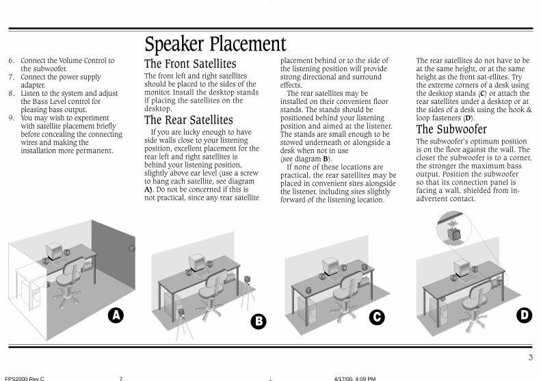
Speaker PlacementThe Front SatellitesThe front left and right satellitesshould be placed to the sides of themonitor. Install the desktop standsif placing the satellites on thedesktop.
The Rear SatellitesIf you are lucky enough to have
side walls close to your listeningposition, excellent placement for therear left and right satellites isbehind your listening position,slightly above ear level (use a screwto hang each satellite, see diagramA). Do not be concerned if this isnot practical, since any rear satellite
The rear satellites do not have to beat the same height, or at the sameheight as the front sat-ellites. Trythe extreme corners of a desk usingthe desktop stands (C) or attach therear satellites under a desktop or atthe sides of a desk using the hook &loop fasteners (D).
The SubwooferThe subwoofer’s optimum positionis on the floor against the wall. Thecloser the subwoofer is to a corner,the stronger the maximum bassoutput. Position the subwooferso that its connection panel isfacing a wall, shielded from in-advertent contact.
placement behind or to the side ofthe listening position will providestrong directional and surroundeffects.
The rear satellites may beinstalled on their convenient floorstands. The stands should bepositioned behind your listeningposition and aimed at the listener.The stands are small enough to bestowed underneath or alongside adesk when not in use(see diagram B).
If none of these locations arepractical, the rear satellites may beplaced in convenient sites alongsidethe listener, including sites slightlyforward of the listening location.
6. Connect the Volume Control tothe subwoofer.
7. Connect the power supplyadapter.
8. Listen to the system and adjustthe Bass Level control forpleasing bass output.
9. You may wish to experimentwith satellite placement brieflybefore concealing the connectingwires and making theinstallation more permanent.
CB
FPS2000 Rev.C 4/17/00, 4:09 PM7

FR
ON
TR
EA
R RF
Front Left Satellite
Rear Left Satellite
Power Supply Adapter
Subwoofer
Front Right Satellite
Audio Connection Cables
Rear Right Satellite
Out ToComputerSound Card
Volume Control
4
Speaker Wiring Diagram
FPS2000 Rev.C 4/17/00, 4:09 PM8

Typically, the 3 meter speakercables will connect the frontsatellites to the subwoofer and the5 meter cables will connect therear satellites to the subwoofer.
A panel of eight self-adhesivelabels is provided to identify eachsatellite and the opposite end ofthe cable connected to a satellite.1. Identify the two 3 meter
cables. Most satellites will beused with their desktopstands. In this case, thread oneend of a 3 meter cable throughthe hole in the desktop stand.Connect this end to onesatellite, (as shown in diagramE). If used, carefully insert thedesktop stand’s attachmentarm into the socket in the backof the satellite, taking up anyslack in the cable as required.
2. Remove the backing from thesmall, round “FRONT LEFT”label and apply it to the backof the satellite (see diagram E).
3. Remove the backing from theremaining, longer “FRONTLEFT” label and wrap itaround the opposite end of thespeaker cable you justconnected.
Satellite Connections
5
4. Connect this end of the speakercable to the red and black“FRONT LEFT” speakerconnectors on the subwoofer.
5. Repeat this process for theFront Right, Rear Right andRear Left satellites. Be sure touse the remaining 3 metercable for the other frontspeaker.
Diagram ETo connect the speaker wires to thespring loaded connectors on thesatellite and subwoofer, push backon a spring-loaded tab to expose theconnection hole. Insert the bare endof the wire into the exposed hole,then release the tab to lock the wirein place.
Connect wires with red bands tored tab connectors and unmarkedwires to black tab connectors.Notes: Matching red wires to redtabs and unmarked wires to blacktabs insures the speakers all play“in-phase”. “Out of phase”connections will do no electricalharm, but the positional audiosound quality will be greatlyreduced. You can substitute regular18 gauge speaker wire to createlonger cables, if needed.
E
FPS2000 Rev.C 4/17/00, 4:09 PM9
REARRIGHT
6
F
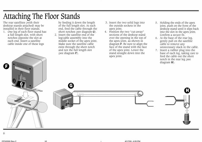
Attaching The Floor Standsby feeding it down the lengthof the full length slot. At eachend, feed the cable through theshort notches (see diagram G).
2. Insert the satellite end of theleg/cable assembly into themiddle socket of the apex joint.Make sure the satellite cableexits through the short notchand not the full length slot(see diagram F).
The rear satellites (with theirdesktop stands attached) may beinstalled in their floor stands.1. One leg of each floor stand has
a full length slot, with shortnotches opposite the slot ateach end. Insert a satellitecable inside one of these legs
3. Insert the two solid legs intothe outside sockets in theapex joint.
4. Position the two “cut-away”sections of the desktop standover the opening in the top ofthe apex joint, as shown indiagram F. Be sure to align theface of the stand with the faceof the apex joint. Lower thestand straight down into theapex joint.
5. Holding the ends of the apexjoint, push on the front of thedesktop stand until it slips backinto the slot in the apex joint.Confirm a secure fit.
6. At the base of the rear leg,gently pull on the satellitecable to remove anyunnecessary slack in the cable.
7. Insert a rubber plug into thebase of each leg, taking care tofeed the cable out the shortnotch in the rear leg (seediagram H).
GH
FPS2000 Rev.C 4/17/00, 4:09 PM10
FPS2000 Digital Subwoofer
FR
ON
TR
EA
R
SOUNDCARD OUTPUT(EXAMPLE-SOUND BLASTER LIVE! AUDIO CARD)
REAROUT
LINEOUT
FR
ON
TR
EA
R
7
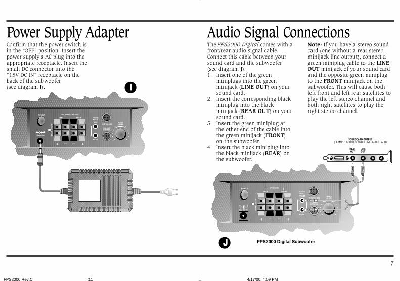
Power Supply AdapterConfirm that the power switch isin the “OFF” position. Insert thepower supply’s AC plug into theappropriate receptacle. Insert thesmall DC connector into the“15V DC IN” receptacle on theback of the subwoofer(see diagram I).
Audio Signal ConnectionsNote: If you have a stereo soundcard (one without a rear stereominijack line output), connect agreen miniplug cable to the LINEOUT minijack of your sound cardand the opposite green miniplugto the FRONT minijack on thesubwoofer. This will cause bothleft front and left rear satellites toplay the left stereo channel andboth right satellites to play theright stereo channel.
The FPS2000 Digital comes with afront/rear audio signal cable.Connect this cable between yoursound card and the subwoofer(see diagram J).1. Insert one of the green
miniplugs into the greenminijack (LINE OUT) on yoursound card.
2. Insert the corresponding blackminiplug into the blackminijack (REAR OUT) on yoursound card.
3. Insert the green miniplug atthe other end of the cable intothe green minijack (FRONT)on the subwoofer.
4. Insert the black miniplug intothe black minijack (REAR) onthe subwoofer.
I
J
FPS2000 Rev.C 4/17/00, 4:09 PM11

FR
ON
TR
EA
R
FPS2000 Digital Subwoofer
FRO
NT
RE
AR
DIGITALDIN
DIGITAL I/O CARD
SPDIF CABLE
Digital DIN Connector
8
If your Sound Blaster Live! soundcard includes a Digital I/O card,you can take advantage of theclear, distortion-free audioavailable from its Digital DINoutput.1. Insert one end of the SPDIF cable
into the DIGITAL DIN output jackon the Sound Blaster Live!Digital I/O card. The position ofthe Digital DIN connector on theDigital I/O card may be differentfrom this diagram. The DigitalDIN connector isthe only connector witha 9-pin configuration.
2. Insert the other end of the SPDIFcable into the DIGITAL DIN inputon the subwoofer (see diagram K).
3. Use the following procedure toconfigure the Sound Blaster Live!sound card for four speakers:• Bring your mouse pointer to the
top of the monitor screen todisplay the Creative Launcher.
• Click on AudioHQ.• Click on the Speaker tab. The
speaker dialog box will appear.
Volume ControlThe FPS2000 Digital system
comes with a separate wiredVolume Control, designed to bepositioned close at hand andaffixed with the semipermanentmounting strip.
Connect the circular plug at theend of the Volume Control into thecircular Volume Control jack onthe back of the subwoofer (seediagram L).
• On the Configuration tabbedpage, select the “4 Speakers”option.
• A sofa icon (representing you)appears in the center of thePreview box, with four speakersat the corners of the box.
Note: The FPS2000 Digital willdetect the presence of a plugconnected to the DIGITAL DINinput and give the DIGITAL DINinput priority. Any signal presentat the AUDIO input will beignored. Be sure to remove theplug from the DIGITAL DIN inputif you wish to listen to a soundsource through the analog AUDIOINPUT.
Connection To Sound Blaster Live! Via DIGITAL DIN
K L
FPS2000 Rev.C 4/17/00, 4:10 PM12

CA
MB
RID
GE
SOU
NDW
OR
KS
9
Using The Volume Controladjustment to its highest setting.Sound Blaster Live! and SoundBlaster Live! Value software hasrear speaker level adjustmentwithin the mixer application. Setthe “FRONT/REAR BALANCE”slider to its mid-way position.
Other sound card software mayhave similar front to rear balanceadjustments. Be sure thesecontrols are set for sufficientoutput in all four channels, thenuse the Front/Rear Balance Controlfrom that point forward.
The Volume Control has a Front/Rear Balance Control, a MasterLevel Control (see diagram M),and an On/Off power switch.
Use the Master Level Controlwhenever you wish to adjust thespeaker output level.
Adjust the Front/Rear BalanceControl to achieve satisfactoryoutput from all four speakers. Itshould not be necessary to adjustthe control more than once whileplaying any single game. Differentgames may benefit from differentFront/Rear Balance Controlsettings.
Software for Creative Labssound cards allows you to adjustthe rear speaker output level. Therear speaker level adjustment isfound within the “CreativeConfigurator” in Sound BlasterPCI64/128 software. Set this
M
Mounting The Volume Control
2 Press exposed adhesive side firmlyagainst back of Volume Control.
Remove protective paper from oneside to reveal adhesive.
4 Press control firmly againstmounting surface(desktop, keyboard or monitor).
Remove remaining paper strip.
The enclosed mounting strip issemipermanent—it holds well butcan be peeled off gently. Be surethat the mounting surface, such asthe computer monitor or yourdesktop, is smooth and clean.
1
3
Front/Rear Balance Control
Master Level Control
FPS2000 Rev.C 4/17/00, 4:10 PM13

FR
ON
TR
EA
R
10
Adjusting Output LevelIn most instances, the FPS2000Digital Master Level Control willbe the most convenient way toadjust the overall playback level. Itresponds instantly and doesn’trequire you to pause games orprograms. But there are otheroutput level controls present insoftware to consider.
Versions of Microsoft® Windows®
and most other operating systemsoffer an on-screen sound levelControl, while most gameprograms provide yet another one.For the FPS2000 Digital MasterLevel Control to perform at itsbest, these “software” levelcontrols should be set to an“optimum” position and then leftalone.
Set any software volumecontrols to approximately 75% oftheir maximum output level. Thisshould allow the FPS2000 DigitalMaster Level Control to achievethe highest output level desiredwhen set to its loudest setting.
If the FPS2000 Digital’smaximum output is still notsufficient at the extreme setting ofits Volume Control, try increasingone, and only one, of the softwarevolume controls to increase overalloutput.
If you find the optimum outputlevel of the FPS2000 Digitalsystem occurs at too low a settingof its Volume Control, reduce thesetting of one software volumecontrol (preferably the operatingsystem’s output level control) toachieve greater control range.Note: Some software volumecontrols may introduce distortionwhen set to their maximum level.Experiment to achieve the cleanestsound.
The output of the subwoofer canbe adjusted to suit the listener’staste. Start with the control in the12 o’clock position (see diagramN). After using the system for acouple of hours, adjust the controlup or down to fine-tune it.
Bass Level Control
N
FPS2000 Rev.C 4/17/00, 4:10 PM14

11
most bass output results from thesubwoofer being placed on the floorin a corner. The least bass outputresults with the unit positioned awayfrom any corners or walls.
Once you have adjusted the BassLevel Control, leave it in thatposition. It should not be used tocompensate for differences inrecordings or games.
The plastic anchors suppliedwill be needed to secure thescrews in most wall surfaces.If so, drill 1/4 inch holes in thewall, then tap the anchors intothe holes until they are flushwith the wall. Then screw thescrews into the anchors untilthey protrude about 1/4 inch.
Be sure to apply the stick-onrubber feet to the back of thesatellite cubes. This assures anacoustically secure installation.
Keyhole slot mounting
Have a clear line of sight from yourlistening position to the satellites.This prevents their higherfrequencies from being blocked. It isnot necessary for each satellite to beaimed directly at the listener.
The relative strength of low-bassdepends on how close the subwooferis to intersecting room surfaces. The
Optimizing The SoundOf Your System
Mounting The SatellitesTo the wall:To wall-mount the cubes onstructurally strong surfaces (a wallstud or wood panelling), screw aM5 x 25mm screw into thematerial. Allow their heads toprotrude about 1/4 inch to fit intothe keyhole slots on the back ofeach cube (see diagram O).
O
FPS2000 Rev.C 4/17/00, 4:10 PM15

12
Technical SupportInside U.S.A., Canada and Latin AmericaCreative Labs Inc. Technical SupportIf you need technical assistance, call 405-742-6622. Technical support isavailable seven days a week from 8:00 am to midnight, Central time.
You can get the latest program and driver updates from Creative Labs’ bulletinboard, 24 hours a day. Call 405-742-6660; use modem settings:
Baud rate: 300 to 14400(V.32/V.42 bis)
Data bits: 8Parity: noneStop bits: 1
You can also send a FAX at 405-742-6633 or write us at:
Technical SupportCreative Labs, Inc.1523 Cimarron PlazaStillwater, OK 74075
To reach Creative Technical support via the Internet, visit our technical supportweb site at http://www.creativehelp.com, for troubleshooting help.
For information about this product and other Creative Labs products, visitCreative Zone at http://www.soundblaster.com. Or, call Customer Service at800-998-1000
Faxback information is available by calling 405-372-5227
ImportantPlayback LevelsFPS2000 Digital is intended forindividual or small group listeningand will achieve surprisingly highoutput levels. However, playingthe system continuously at overlyloud, distorted levels on heavybass program material may causeits internal fuse to blow.
The fuse can be replaced only bya qualified service representative.To avoid this inconvenience and apossible non-warranty repaircharge, reduce the playbackvolume when the system showsobvious signs of stress, i.e. itsounds “raspy,” “fuzzy,” and/or “muddy.”
SpecificationsFPS2000 Digital’s
Four-channelAmplifier Specifications
Subwoofer: 25 watts RMS.
Satellite: 7 watts RMS per channel.
These specifications apply to aFPS2000 Digital operating from a15V DC power adapter.
FPS2000 Rev.C 4/17/00, 4:10 PM16

13
Inside AsiaCreative Technology Ltd. Technical Support31 International Business Park,Creative Resource, Singapore 609921
Tel: +65 8954100Fax: +65 5696640
Operating hours (Singapore Time)Mon-Fri: 9am-6pmSat-Sun & Public Holidays: Closed
1-Year Limited Warrantyo the original purchaser,Cambridge SoundWorks, Inc.will warrant the FPS2000Digital system to be free of
defects in material andworkmanship for a period of one(1) year from date of purchase.With respect to defects, CambridgeSoundWorks will, at its option,replace the product or repair thedefect in the product with nocharge to the original purchaserfor parts or labor.
This warranty does not extendto any defect, malfunction orfailure caused by misuse, abuse,accident, faulty hook-up, defectiveassociated equipment or use of thespeaker with equipment for whichit is not intended.
This warranty is valid onlywhen the speaker is returned tothe retailer that sold the FPS2000Digital to the original purchaser.
T This is the sole and expressedwarranty. This warranty is in lieuof all other warranties, expressedor implied, of merchantability,fitness for purpose or otherwise.In no event shall CambridgeSoundWorks, Inc. be liable forincidental or consequentialdamages or have any liability withrespect to defects other than theobligations set forth as stated.
To ensure warranty coverage, itis incumbent upon the originalpurchaser of FPS2000 Digital toinform the retailer of the defectwithin the warranty period. Theonly acceptable method ofestablishing warranty status is acopy of the original proof ofpurchase indicating customersname and purchase date.
For advice about your warrantyor any information, call the storewhere purchased or refer to the“Technical Support” section onpages 12-13.
© 2000 Cambridge SoundWorks, Inc. All rights reserved. Cambridge SoundWorks is a registered trademark, and FourPointSurround is a trademark of Cambridge SoundWorks, Inc., Newton, MA.Creative and Sound Blaster are registered trademarks of Creative Technology Ltd. All other brands and products are trademarks or registered trademarks of their respective holders. Allspecifications are subject to change without prior notice. Actual contents may differ from those pictured.
FPS2000 Rev.C 4/17/00, 4:10 PM17

FPS2000 Rev.C 4/17/00, 4:10 PM18

FPS2000 Rev.C 4/17/00, 4:10 PM19

311 Needham Street, Newton, MA 024641-877-937-4434 Fax: 617-527-3194www.cambridgesoundworks.com
or e-mail us at [email protected]
0420003004 Rev. C
FPS2000 Rev.C 4/17/00, 4:10 PM20