fpo userguide april 2015 - jeppesen
TRANSCRIPT

CHAPTER 1
Introduction
The Jeppesen FlitePlan Online User Guide provides instructions for using Jeppesen FlitePlan Online (FPO), a web-based application that enables pilots to create, file, and manage flight plans from anywhere in the world in minutes.
This section includes the following topics:
• About the User Guide
• References
• Product Support
• Conventions Used in This Guide

IntroductionAbout the User Guide
Je2
About the User Guide Boeing
Jeppesen
This User Guide provides detailed instructions for using Jeppesen FlitePlan Online. It includes initial setup instructions, information about the various parts of the application, and steps to complete some common tasks.
Using Help
Select the question mark icon to access Jeppesen FlitePlan Online help.
You have two options:
• Tutorials leads you to the Articulate Storyline e-learning module of Jeppesen FlitePlan Online. Use the tutorial to become familiar with the interface, navigation, and how to perform key tasks.
• Help displays the online documentation.
Use these icons at the top of FPO Help to locate topics and information:
Notes provide additional information about a topic.
Tips provide helpful hints for tasks.
Icon Description
Contents—Provides a hierarchy of each topic in the FPO Help. Use the contents if you want more information about a particular area in FPO.
Index—Provides a list of key terms. Use the index if you want to find a key word and do not want to scroll through a list of search results.
Glossary—Provides a list of relevant terms and acronyms with their definitions.
Search—Enables you to search through all help topics for a particular search term. Use Search if you know the key word or phrase and want to see the results in multiple topics.
ppesen FlitePlan Online User Guide February 2015Copyright © 2015 Jeppesen. All rights reserved.

IntroductionAbout the User Guide
FeCo
Intended AudienceThe primary audience for this documentation is business aviation pilots, flight planners, dispatchers, and others who use Jeppesen FlitePlan Online to create and file flight plans.
Assumptions
This document assumes that you are conversant with:
• The terms and definitions that relate to flight planning and filing as specified by the FAA.
• Browsers supported by Jeppesen.
bruary 2015 Jeppesen FlitePlan Online User Guidepyright © 2015 Jeppesen. All rights reserved. 3

IntroductionReferences
Je4
ReferencesYou may find the following documents useful. Contact your Jeppesen account manager to obtain these manuals:
• JetPlan User Manual
• JetPlan.com User Guide
• Procedures for Air Navigation Services — Aircraft Operations (PANS-OPS, Doc 8168), Volume I — Flight Procedures
ppesen FlitePlan Online User Guide February 2015Copyright © 2015 Jeppesen. All rights reserved.

IntroductionProduct Support
FeCo
Product Support
Jeppesen provides technical support 24 hours a day, 7 days a week.
North America Toll-Free: 800-537-7225
United States Direct: 303-328-4170
United Kingdom: 44-1293-842407
Australia: 61-73105-9450
All Other International: 49-6102-507004
Email: [email protected]
bruary 2015 Jeppesen FlitePlan Online User Guidepyright © 2015 Jeppesen. All rights reserved. 5

IntroductionConventions Used in This Guide
Je6
Conventions Used in This Guide
This guide uses the following conventions:
Table 1-1 Conventions Used in This Guide
Convention Description
Select Select indicates either the click or tap actions, depending on the browser you are using and the operating system (Windows, OSX, and iOS).
Steps in procedures in this online guide do not repeat the “select” action for each interface element such as “Select <check box> or <button>.” This document assumes that you either click or tap to interact with the interface element when following the steps in a procedure.
See About the Jeppesen FlitePlan Online Interface.
navaid The Jeppesen documentation convention is navaid when referring to Jeppesen navigational aids. Sometimes you may find NAVAID (in all capitals) in this document when it refers to a specific item in the interface such as a check box.
Blue text Indicates a hyperlink to a heading or subheading in the same or another topic.
Boldface Button and box names and other controls appear in boldface type within steps when you have specific instructions to interact with an interface element.
ppesen FlitePlan Online User Guide February 2015Copyright © 2015 Jeppesen. All rights reserved.
CHAPTER 2
Getting Started
This section introduces Jeppesen FlitePlan Online and consists of the following topics:
• The Basics
• Using Jeppesen FlitePlan Online
• About the Jeppesen FlitePlan Online Interface
• Performing Basic Tasks
Before You BeginBefore you begin using Jeppesen FlitePlan Online, follow the tutorial to become familiar with it. See Using Help.
Getting StartedThe Basics
Je8
The BasicsThis section describes the basic requirements for the software you need to set up your environment to use Jeppesen FlitePlan Online, as well as basic tasks.
BrowsersJeppesen supports the following browsers:
• Chrome, IE9+, and Firefox version 26 or higher on Windows
• Safari on OSX and iOS
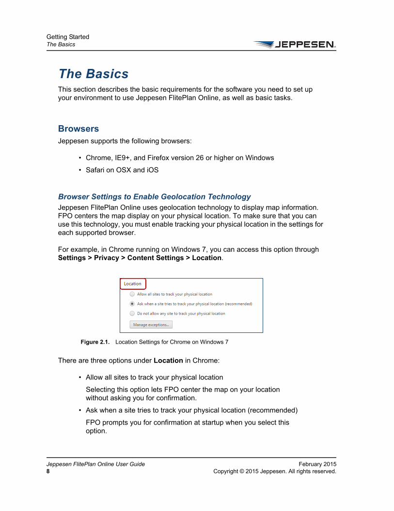
Browser Settings to Enable Geolocation TechnologyJeppesen FlitePlan Online uses geolocation technology to display map information. FPO centers the map display on your physical location. To make sure that you can use this technology, you must enable tracking your physical location in the settings for each supported browser.
For example, in Chrome running on Windows 7, you can access this option through Settings > Privacy > Content Settings > Location.
There are three options under Location in Chrome:
• Allow all sites to track your physical location
Selecting this option lets FPO center the map on your location without asking you for confirmation.
• Ask when a site tries to track your physical location (recommended)
FPO prompts you for confirmation at startup when you select this option.
Figure 2.1. Location Settings for Chrome on Windows 7
ppesen FlitePlan Online User Guide February 2015Copyright © 2015 Jeppesen. All rights reserved.

Getting StartedThe Basics
FeCo
• Do not allow any site to track your physical location
You will not be able to use the FPO geolocation technology if you select this option.
Screen Resolution
Set the screen resolution to 1024 x 768 or higher for browsers.
Notifications
Jeppesen FlitePlan Online displays various notifications during logon if any of the following conditions apply:
• Jeppesen FlitePlan Online is experiencing downtime.
• Jeppesen systems are undergoing maintenance.
• JetPlan is experiencing downtime.
• You are using an unsupported browser.
Logging on and Logging OutJeppesen FlitePlan Online requires you to log on with a valid username and password. Jeppesen provides a temporary password that you must change after you first log on.
To log on to Jeppesen FlitePlan Online
1. Go to the Jeppesen FlitePlan Online login page.
2. Enter your user credentials in the Username and Password boxes.
3. Select Login.
If you forget your username or password, see Resetting a Forgotten Username and Password.
To log out of Jeppesen FlitePlan Online
• On the tool bar, select Logout.
bruary 2015 Jeppesen FlitePlan Online User Guidepyright © 2015 Jeppesen. All rights reserved. 9

Getting StartedThe Basics
Je10
Resetting a Forgotten Username and PasswordTo reset your username or password for Jeppesen FlitePlan Online:
1. On the login page, at the bottom of the Login area, select Forgot username/password?
2. In the Reset Password dialog box, type the username and email address used to create the account.
3. Select Submit.
The system validates that the username and email address entered exist on the same account and that the account is active. A message notifies you that your password has been reset and that a temporary new password has been sent to your email address.
4. Retrieve the temporary password from the email message and use it to log on.
You are required to change your temporary password. See Changing Your Password for more information.
Changing Your PasswordTo change your password:
1. On the tool bar, select Settings > Change My Password.
2. In the Current Password box, type your current password.
3. In the New Password box, type your new password.
4. In the Confirm New Password box, retype your new password.
5. Select Submit.
ppesen FlitePlan Online User Guide February 2015Copyright © 2015 Jeppesen. All rights reserved.

Getting StartedUsing Jeppesen FlitePlan Online
FeCo
Using Jeppesen FlitePlan Online
Flight plans in Jeppesen FlitePlan Online utilize Jetplan, the core engine behind Jeppesen’s flight-planning tools such as JetPlanner, Jeppesen Dispatch Control, JetPlan.com, and Jeppesen FlitePlan Online. Jeppesen FlitePlan Online also uses the following databases from Jetplan for flight planning information:
• Customer Aircraft Database (CACDB)
• Aircraft Fleet Database (ACFDB)
• Airport Fleet Database (APFDB)
• Customer Routes Database
You can begin using Jeppesen FlitePlan Online to create and file flight plan and publish flight packages when your Jeppesen account manager notifies you that Jeppesen has completed creating your account setup, including connecting to Jetplan.
Jeppesen FlitePlan Online allows you to create a new flight plan in three ways. See Creating Flight Plans.
To familiarize yourself with navigating around Jeppesen FlitePlan Online, see About the Jeppesen FlitePlan Online Interface.
bruary 2015 Jeppesen FlitePlan Online User Guidepyright © 2015 Jeppesen. All rights reserved. 11
Getting StartedUsing Jeppesen FlitePlan Online
Je12
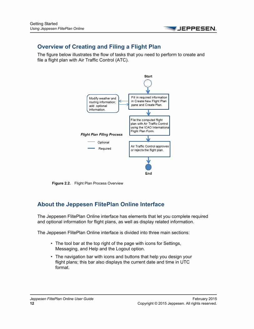
Overview of Creating and Filing a Flight PlanThe figure below illustrates the flow of tasks that you need to perform to create and file a flight plan with Air Traffic Control (ATC).
About the Jeppesen FlitePlan Online Interface
The Jeppesen FlitePlan Online interface has elements that let you complete required and optional information for flight plans, as well as display related information.
The Jeppesen FlitePlan Online interface is divided into three main sections:
• The tool bar at the top right of the page with icons for Settings, Messaging, and Help and the Logout option.
• The navigation bar with icons and buttons that help you design your flight plans; this bar also displays the current date and time in UTC format.
Figure 2.2. Flight Plan Process Overview
ppesen FlitePlan Online User Guide February 2015Copyright © 2015 Jeppesen. All rights reserved.

Getting StartedUsing Jeppesen FlitePlan Online
FeCo
• The main information area with left and right panes
bruary 2015 Jeppesen FlitePlan Online User Guidepyright © 2015 Jeppesen. All rights reserved. 13
Getting StartedUsing Jeppesen FlitePlan Online
Je14
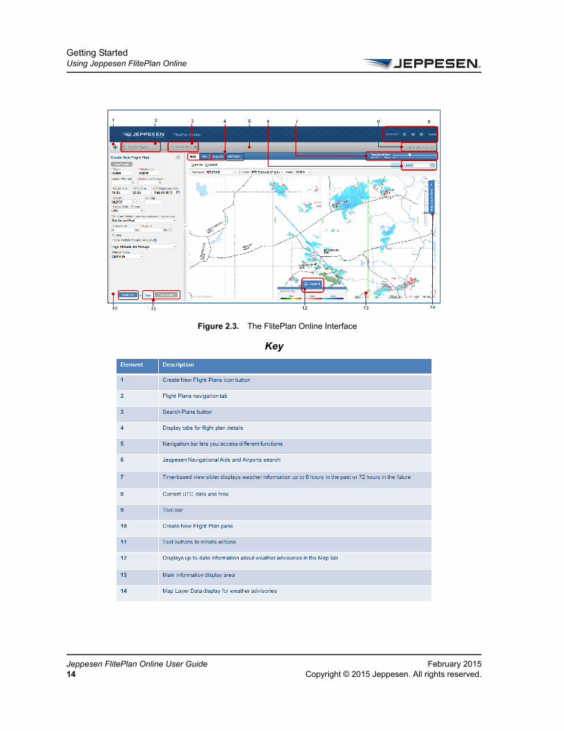
Figure 2.3. The FlitePlan Online Interface
Key
ppesen FlitePlan Online User Guide February 2015Copyright © 2015 Jeppesen. All rights reserved.

Getting StartedUsing Jeppesen FlitePlan Online
FeCo
The topics below describe the interface in detail:
• Tool Bar
• Navigation Bar
• The Create New Flight Plan Pane
• The Active and History Panes
• Flight Plan Details Display Tabs
Tool Bar
The Jeppesen FlitePlan Online tool bar, located in the upper right corner of the main page, provides quick access to tools that help you manage your user account and your flight plans. For more information about the tool bar, see About the Jeppesen FlitePlan Online Interface.
bruary 2015 Jeppesen FlitePlan Online User Guidepyright © 2015 Jeppesen. All rights reserved. 15

Getting StartedUsing Jeppesen FlitePlan Online
Je16
The tool bar contains icons for each of the tools in the table below.
Table 2-1 Jeppesen FlitePlan Online Tool Bar Options
Icon/Option Name Description
Settings The Settings icon has the following options that you can select:
• Edit User Profile
View your user and your company information, such as name, address, and phone number. You can edit some of this information.
• Change My Password
Access the Change Password dialog box.
• Edit User Preferences
View or edit the flight planning options that are based on your preferences. These options relate to date format, weight and balance, wind source, and fuel reserve policies.
• Weight & Balance Configuration
View a list of weight and balance configurations. You can also modify the list.
• Airport RAIM Prediction
Generate a RAIM prediction report for an airport that you select.
To generate RAIM reports for all the airports in your flight plan package, see Generating a RAIM Prediction Report for a Flight Plan Package.
Messaging The Messaging icon has the following options that you can select:
• Send Message
View the Messaging navigation tab. You can send flight plans, text messages, and attachments. You can also maintain a history of sent messages.
• Manage Contacts
View the Address Book navigation tab, which is a directory of your contact information for messaging.
Help View Tutorials or online documentation for Jeppesen FlitePlan Online. See Using Help.
Logout Logout Log out of Jeppesen FlitePlan Online.
ppesen FlitePlan Online User Guide February 2015Copyright © 2015 Jeppesen. All rights reserved.

Getting StartedUsing Jeppesen FlitePlan Online
FeCo
Navigation BarThe navigation bar allows you access different parts of Jeppesen FlitePlan Online and displays the current UTC date and time. You have the following options:
• Create a Flight Plan icon (+) to create a new flight plan using the Flight Plan pane
• Flight Plans tab to select and view an existing flight plan
• Search Plans button to search for an existing flight plan using the flight plan number in either Jeppesen FlitePlan Online or JetPlan.com
For more information about the navigation bar, see About the Jeppesen FlitePlan Online Interface.
The Create New Flight Plan Pane
In Jeppesen FlitePlan Online, you create flight plans using basic options on the Create New Flight Plan pane. For more information about using the flight plan pane, see Creating Flight Plans.
bruary 2015 Jeppesen FlitePlan Online User Guidepyright © 2015 Jeppesen. All rights reserved. 17

Getting StartedUsing Jeppesen FlitePlan Online
Je18
By default, the Create New Flight Plan pane appears on the left side of the page when you log on to Jeppesen FlitePlan Online. Use the basic options in this pane to enter all of the required information for calculating a flight plan. See Completing Basic Flight Plan Information
Select the double arrow button to the right of the flight plan page to view extended flight plan options (such as Destination Alternates). See Viewing Additional Flight Plan Options.
Figure 2.4. The Create New Flight Plan Pane
ppesen FlitePlan Online User Guide February 2015Copyright © 2015 Jeppesen. All rights reserved.

Getting StartedUsing Jeppesen FlitePlan Online
FeCo
Viewing Additional Flight Plan Options
The Advanced Flight Options pane is hidden until you select View Package in the Active or History pane for an existing flight plan.
When you select View Package, Jeppesen FlitePlan Online displays Advanced Flight Options in the left pane and the flight plan summary and its details in the main window. See Advanced Flight Plan Options for Existing Flight Plans.
Figure 2.5. Active, View Package, and History options for an Existing Flight Plan
bruary 2015 Jeppesen FlitePlan Online User Guidepyright © 2015 Jeppesen. All rights reserved. 19

Getting StartedUsing Jeppesen FlitePlan Online
Je20
Advanced Flight Plan Options for Existing Flight Plans
Use the Advanced Flight Options pane to select, update, or edit additional options in selected flight plans. The information you can view varies based on the options you select.
Flight Plan View the entire flight plan summary. You can choose to view only Alerts and/or Filing History for the flight plan.
Select these check boxes to view or update information (including weather advisories) in your flight plan:
• Wx (Airports only) (weather details)
• Update (weather details)
• Include Enroute
• METARs
• TAFs
• Winds Aloft (Weather forecast for winds and temperatures aloft
• AIRMETs
• SIGMETs
• Convective SIGMETs
• Center Weather Advisory
• Severe Weather Advisory
Figure 2.6. Main Window with Advanced Flight Plan Options and Flight Plan Summary
ppesen FlitePlan Online User Guide February 2015Copyright © 2015 Jeppesen. All rights reserved.
Getting StartedUsing Jeppesen FlitePlan Online
FeCo
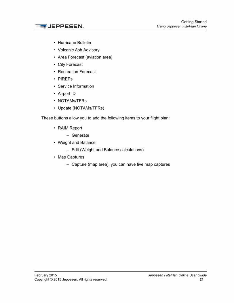
• Hurricane Bulletin
• Volcanic Ash Advisory
• Area Forecast (aviation area)
• City Forecast
• Recreation Forecast
• PIREPs
• Service Information
• Airport ID
• NOTAMs/TFRs
• Update (NOTAMs/TFRs)
These buttons allow you to add the following items to your flight plan:
• RAIM Report
– Generate
• Weight and Balance
– Edit (Weight and Balance calculations)
• Map Captures
– Capture (map area); you can have five map captures
bruary 2015 Jeppesen FlitePlan Online User Guidepyright © 2015 Jeppesen. All rights reserved. 21

Getting StartedUsing Jeppesen FlitePlan Online
Je22
The Active and History PanesUse the Active and History panes to view flight plans that have already been computed.
On the navigation bar, select Flight Plans to access the Active and History panes. The Active pane displays flight plans that have not been flown; the History pane displays flight plans that have already been flown.
If the ETD of the flight plan occurs in the future or less than one hour in the past, the plan appears in the Active pane; if the ETD of the flight plan occurs at least one hour in the past, the plan appears in the History pane. The History pane displays all flight plans with an ETD of at least one hour prior to the current time.
Figure 2.7. Active and History panes in the Flight Plans Tab
ppesen FlitePlan Online User Guide February 2015Copyright © 2015 Jeppesen. All rights reserved.

Flight Plan Details Display TabsWhen you log in to Jeppesen FlitePlan Online, the right pane under the navigation bar displays four display tabs: Map, Wx, Airports, and NOTAMs. These display tabs show details about the selected flight plan and you cannot use them to edit the flight plan.
The Map, Wx, Airports, and NOTAMs tabs are explained briefly below.
Map tab The Map tab displays the selected flight plan on a digital navigation chart. Use the options in the Map Layers dropdown menu to select weather advisory details to display.t
Legend
Figure 2.8. Flight Plan Details Display Tabs
Figure 2.9. Map Tab with Legend

Getting StartedUsing Jeppesen FlitePlan Online
Je24
The Legend at the bottom of the Map tab graphically displays details about the selected map layer.
Map Layer Data
Expand or collapse the Map Layer Data display to view the duration for which the weather advisory in the map layer is in effect. See About the Jeppesen FlitePlan Online Interface.
Wx tab The Wx tab displays weather information for the selected airports. Select the weather items that you want to view for the airports in the Weather Types dropdown menu.
Airports tab The Airports tab displays details for selected airports such as runways, hotels, handlers, and transportation companies. You can also opt to view a PDF of the airport diagram.
Figure 2.10. Wx Tab with Weather Types Dropdown Menu and Related Display Information
ppesen FlitePlan Online User Guide February 2015Copyright © 2015 Jeppesen. All rights reserved.

Getting StartedUsing Jeppesen FlitePlan Online
FeCo
Select the airport radio button to view its related information.
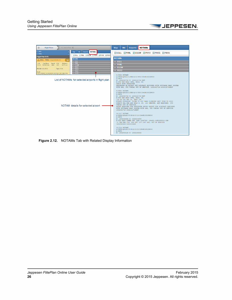
NOTAMs tab The NOTAMs tab displays NOTAMs that pertain to the airports selected in the airport options area at the top of the tab. NOTAMs are displayed in ICAO format. The following NOTAM types are automatically filtered out:
• Jeppesen Chart
• Jeppesen NavData
• Jeppesen Publication NOTAMs
Jeppesen Fliteplan Online applies the ICAO Format to the Airport and FIR Boundary NOTAM text.
Figure 2.11. Airports Tab with Related Displayed Information
bruary 2015 Jeppesen FlitePlan Online User Guidepyright © 2015 Jeppesen. All rights reserved. 25
Getting StartedUsing Jeppesen FlitePlan Online
Je26
Figure 2.12. NOTAMs Tab with Related Display Information
ppesen FlitePlan Online User Guide February 2015Copyright © 2015 Jeppesen. All rights reserved.

Getting StartedPerforming Basic Tasks
FeCo
Performing Basic TasksThis section describes how to perform basic tasks throughout Jeppesen FlitePlan Online. These tasks are:
• Searching for Information
•
Searching for Information
You can search for information in several areas where the data may exist in Jeppesen FlitePlan Online.
You can search for information in the following ways:
1. To search for Origin, Destination, Takeoff Alternate, or Destination Alternates, type in at least the first three letters of the airport city name, airport name, ICAO code, or IATA code in the respective boxes to view a list of all matching airports and available codes.
2. After you have selected the Origin and Destination airports, use the magnifying glass icon next to the Take-off Alternate or Destination Alternate boxes to search for airports. For details, see About Searches for Alternate Takeoffs and Destinations.
• Type the first three letters of the alternate city name, airport name, ICAO code, or IATA code to view a list of all matching airports and available codes.
Figure 2.13. Searching for Origin and Destination Airports
bruary 2015 Jeppesen FlitePlan Online User Guidepyright © 2015 Jeppesen. All rights reserved. 27

Getting StartedPerforming Basic Tasks
Je28
3. Use the Search Plans button to search for existing flight plans. You must have the exact flight plan number to be able to search for it.
4. Use the Search box to search for Jeppesen navigational aids and airports. Drill down further in the search results to display additional details such as latitude and longitude. Type in at least two characters to perform this multilevel search.
Figure 2.14. Using the Search Flight Plans Dialog Box
Figure 2.15. Using the Search Box with Two Characters
ppesen FlitePlan Online User Guide February 2015Copyright © 2015 Jeppesen. All rights reserved.

CHAPTER 3
Working with Flight Plans
This section explains how to create and manage flight plans and has the following topics:
• Creating Flight Plans
• Viewing Flight Plans
• Managing Favorite Flight Plans
• Managing Flight Plan Packages

Working with Flight PlansCreating Flight Plans
Je30
Creating Flight Plans
A flight plan generally includes basic information such as departure and arrival points, estimated time en route, alternate airports in case of bad weather, type of flight (whether instrument flight rules [IFR] or visual flight rules [VFR]), fuel requirements, route, speed, flight levels, the pilot's information, number of people on board, and information about the aircraft.
To create a new flight plan in Jeppesen FlitePlan Online, you can:
• Create a flight plan with new values for required and optional information.
• Update a saved favorite flight plan and save it as a new plan.
• Revise and recompute a previously computed flight plan and save it as a new plan (or as a favorite).
• Recompute a previously computed flight plan (with route changes if you like) and save it as a new plan (or as a favorite).
This section consists of the following tasks:
• Create a Flight Plan with New Values
• Revise a Previously Computed Flight Plan
• Completing Basic Flight Plan Information
• About Searches for Alternate Takeoffs and Destinations
• About Fuel and Payload Options
• Routing Options in the Create New Flight Plan Pane
• About the Advanced Flight Options Pane
• Managing Favorite Flight Plans
• Saving a Flight Plan as a Favorite
• Updating a Favorite Flight Plan
• Sorting Favorite Flight Plans
• Deleting Favorite Flight Plans
A flight plan must include payload information for filing. See Filing a Flight Plan.
ppesen FlitePlan Online User Guide February 2015Copyright © 2015 Jeppesen. All rights reserved.

Working with Flight PlansCreating Flight Plans
FeCo
Create a Flight Plan with New ValuesYou can create a new flight plan by providing new values for your intended flight.
To create a new flight plan with new values:
1. Select the Plus (+) button on the navigation bar.
For more information, see Navigation Bar.
2. In the Create New Flight Plan page, type or select the appropriate information in the boxes described in Basic Flight Plan Information to Enter in the Create New Flight Plan Form.
For information about the values to enter in the boxes, see Completing Basic Flight Plan Information.
3. If you want to enter additional information for the flight plan, select the double arrow button at the top of the Create New Flight Plan tab. This opens the Advanced Flight Options pane.
For more information about advanced options, see About the Advanced Flight Options Pane.
4. Select Create Plan when you finish entering information in all the boxes.
Optionally, you can select Save Favorite to save the plan information as a favorite, or you can select Clear to clear existing input on the flight plan form. For information about favorites, see Saving a Flight Plan as a Favorite.
Revise a Previously Computed Flight PlanYou can create a flight plan by revising a previously computed flight plan, and change the values you choose. You can also use the following procedure to reuse a previously computed flight plan without making changes.
To create a new flight plan by revising a previously computed flight plan:
1. On the navigation bar, select the Flight Plans tab.
For more information about the Flight Plans tab, see About the Jeppesen FlitePlan Online Interface.
bruary 2015 Jeppesen FlitePlan Online User Guidepyright © 2015 Jeppesen. All rights reserved. 31

Working with Flight PlansCreating Flight Plans
Je32
2. If you want to select a flight that has already been flown, select the History pane.
For more information about the History pane, see The Active and History Panes.
3. Select the desired flight plan from either the Active or History pane.
An overview of the flight appears at the top of the selected pane.
4. Revise the flight plan as you need.
5. Select Create Plan.
Completing Basic Flight Plan InformationThis section describes how to complete required and basic information in the Create New Flight Plan pane. See About the Advanced Flight Options Pane for additional options that you can add to your flight plan.
To enter information in the Origin, Takeoff Alternate, Destination, and Destination Alternate boxes:
1. Type at least the first three letters of the originating city name, airport name, or International Civil Aviation Organization (ICAO) or International Air Transport Association (IATA) code to generate a list of all matching airports available.
2. Select the desired airport.
See also About Searches for Alternate Takeoffs and Destinations.
3. Enter information in the following time boxes:
The table below describes the boxes in the Create New Flight Plan form.
Required items are indicated by an asterisk.
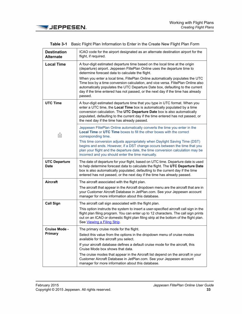
Table 3-1 Basic Flight Plan Information to Enter in the Create New Flight Plan Form
Box Name Description
Origin ICAO code for the airport from which the flight originates.
Takeoff Alternate ICAO code for the airport designated as an alternate takeoff airport for the flight, if required.
Destination ICAO code for the destination airport.
ppesen FlitePlan Online User Guide February 2015Copyright © 2015 Jeppesen. All rights reserved.
Working with Flight PlansCreating Flight Plans
FeCo
Destination Alternate
ICAO code for the airport designated as an alternate destination airport for the flight, if required.
Local Time A four-digit estimated departure time based on the local time at the origin (departure) airport. Jeppesen FlitePlan Online uses the departure time to determine forecast data to calculate the flight.
When you enter a local time, FlitePlan Online automatically populates the UTC Time box by a time conversion calculation, and vice versa. FlitePlan Online also automatically populates the UTC Departure Date box, defaulting to the current day if the time entered has not passed, or the next day if the time has already passed.
UTC Time A four-digit estimated departure time that you type in UTC format. When you enter a UTC time, the Local Time box is automatically populated by a time conversion calculation. The UTC Departure Date box is also automatically populated, defaulting to the current day if the time entered has not passed, or the next day if the time has already passed.
Jeppesen FlitePlan Online automatically converts the time you enter in the Local Time or UTC Time boxes to fill the other boxes with the correct corresponding time.
This time conversion adjusts appropriately when Daylight Saving Time (DST) begins and ends. However, if a DST change occurs between the time that you plan your flight and the departure date, the time conversion calculation may be incorrect and you should enter the time manually.
UTC Departure Date
The date of departure for your flight, based on UTC time. Departure date is used to help determine forecast data to calculate the flight. The UTC Departure Date box is also automatically populated, defaulting to the current day if the time entered has not passed, or the next day if the time has already passed.
Aircraft The aircraft associated with the flight plan.
The aircraft that appear in the Aircraft dropdown menu are the aircraft that are in your Customer Aircraft Database in JetPlan.com. See your Jeppesen account manager for more information about this database.
Call Sign The aircraft call sign associated with the flight plan.
This option instructs the system to insert a user-specified aircraft call sign in the flight plan filing program. You can enter up to 12 characters. The call sign prints out on an ICAO or domestic flight plan filing strip at the bottom of the flight plan. See Viewing a Filing Strip.
Cruise Mode - Primary
The primary cruise mode for the flight.
Select this value from the options in the dropdown menu of cruise modes available for the aircraft you select.
If your aircraft database defines a default cruise mode for the aircraft, this Cruise Mode box shows that data.
The cruise modes that appear in the Aircraft list depend on the aircraft in your Customer Aircraft Database in JetPlan.com. See your Jeppesen account manager for more information about this database.
Table 3-1 Basic Flight Plan Information to Enter in the Create New Flight Plan Form
bruary 2015 Jeppesen FlitePlan Online User Guidepyright © 2015 Jeppesen. All rights reserved. 33

Working with Flight PlansCreating Flight Plans
Je34
Fuel and Payload Select this value from the dropdown list of methods for determining fuel and payload. You can plan the flight according to arrival and departure fuel and weight values. For more information on each option, see About Fuel and Payload Options.
Arrival Fuel The Arrival Fuel box value changes between various fuel and weight contexts depending on the value you select in the Fuel and Payload box.
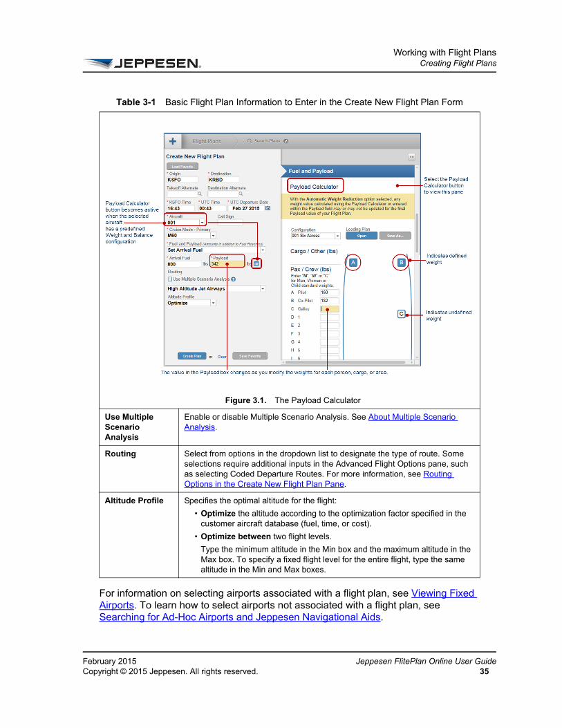
Payload The amount of payload to be transported. The value you enter must be within the defined limits for the aircraft. A warning message appears if the payload you define is over the maximum value for the selected aircraft. You must change the payload to an allowable value to create the flight plan.
You can type “0” as a value in the Payload box.
If you select an aircraft that already has a weight and balance configuration, the Payload Calculator button becomes active and you can select it to edit the payload. FPO gives you a choice between entering a value in the Payload box or using the Payload Calculator
If you have defined a Payload value, using the Payload Calculator will delete the payload value you entered. You can choose to continue if you like.
Table 3-1 Basic Flight Plan Information to Enter in the Create New Flight Plan Form
ppesen FlitePlan Online User Guide February 2015Copyright © 2015 Jeppesen. All rights reserved.
Working with Flight PlansCreating Flight Plans
FeCo
For information on selecting airports associated with a flight plan, see Viewing Fixed Airports. To learn how to select airports not associated with a flight plan, see Searching for Ad-Hoc Airports and Jeppesen Navigational Aids.
Figure 3.1. The Payload Calculator
Use Multiple Scenario Analysis
Enable or disable Multiple Scenario Analysis. See About Multiple Scenario Analysis.
Routing Select from options in the dropdown list to designate the type of route. Some selections require additional inputs in the Advanced Flight Options pane, such as selecting Coded Departure Routes. For more information, see Routing Options in the Create New Flight Plan Pane.
Altitude Profile Specifies the optimal altitude for the flight:
• Optimize the altitude according to the optimization factor specified in the customer aircraft database (fuel, time, or cost).
• Optimize between two flight levels.
Type the minimum altitude in the Min box and the maximum altitude in the Max box. To specify a fixed flight level for the entire flight, type the same altitude in the Min and Max boxes.
Table 3-1 Basic Flight Plan Information to Enter in the Create New Flight Plan Form
bruary 2015 Jeppesen FlitePlan Online User Guidepyright © 2015 Jeppesen. All rights reserved. 35
Working with Flight PlansCreating Flight Plans
Je36
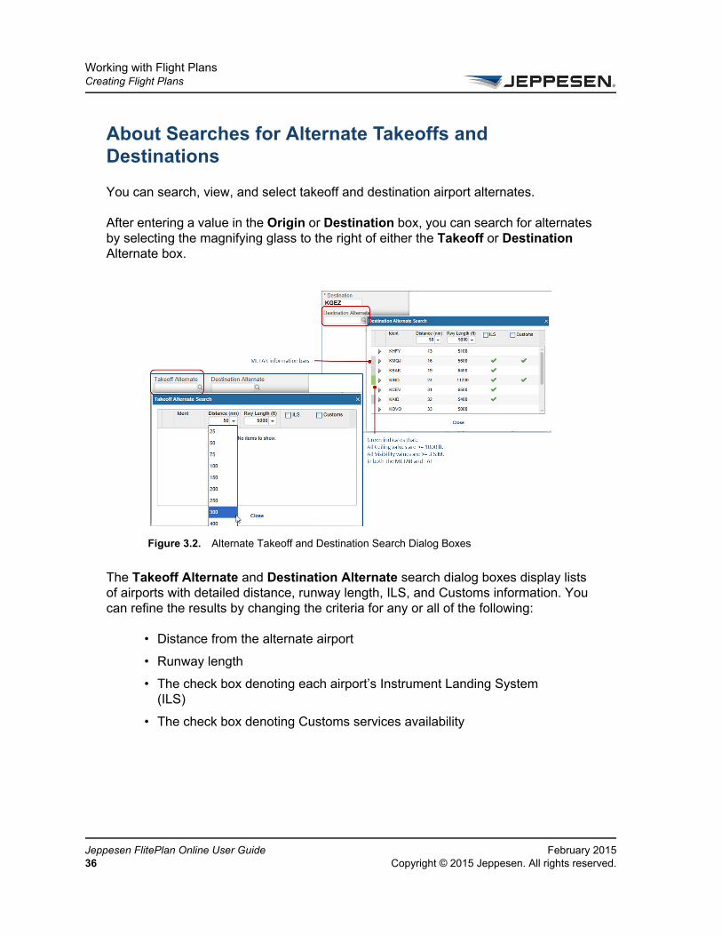
About Searches for Alternate Takeoffs and Destinations
You can search, view, and select takeoff and destination airport alternates.
After entering a value in the Origin or Destination box, you can search for alternates by selecting the magnifying glass to the right of either the Takeoff or Destination Alternate box.
The Takeoff Alternate and Destination Alternate search dialog boxes display lists of airports with detailed distance, runway length, ILS, and Customs information. You can refine the results by changing the criteria for any or all of the following:
• Distance from the alternate airport
• Runway length
• The check box denoting each airport’s Instrument Landing System (ILS)
• The check box denoting Customs services availability
Figure 3.2. Alternate Takeoff and Destination Search Dialog Boxes
ppesen FlitePlan Online User Guide February 2015Copyright © 2015 Jeppesen. All rights reserved.

Working with Flight PlansCreating Flight Plans
FeCo
You can also mouse-over the METAR information for each airport (bars at left). Color coding in the search pane displays changes based on weather information. See Table 3-2 for details.
Airport Display Criteria
Airports are displayed based on the following criteria:
• Maximum distance from the origin or destination airport
• Minimum runway length
• ILS capability of the airport
• Customs availability
• Airport Type
About Fuel and Payload OptionsThe Fuel and Payload dropdown menu has options for specifying the fuel and weight information for the flight plan. You can specify either arrival or departure fuel or weight values.
• If you choose an arrival value, Jeppesen FlitePlan Online calculates your departure weight and fuel load to meet your arrival specifications.
Table 3-2 Alternate Search Legend
Color Description
White Both TAF and METAR are unavailable.
Gray METAR information is available, but TAF is not.
Yellow METAR or TAF contains one or more Ceiling < 1000 ft or Visibility < 3 S.M. in both the METAR and TAF.
Green All Ceiling values are >= 1000 ft, and all Visibility values are >= 3 S.M. in both the METAR and TAF
Default values are set in User Preferences. See Managing User Profiles and Preferences.
bruary 2015 Jeppesen FlitePlan Online User Guidepyright © 2015 Jeppesen. All rights reserved. 37
Working with Flight PlansCreating Flight Plans
Je38
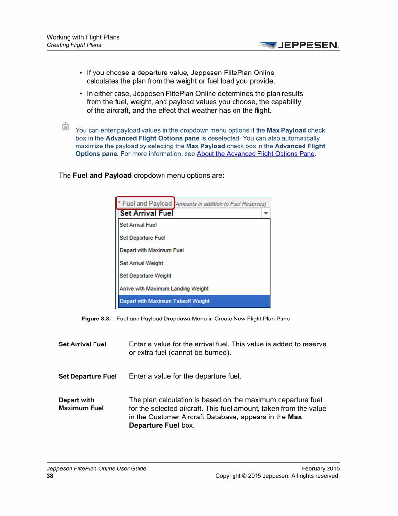
• If you choose a departure value, Jeppesen FlitePlan Online calculates the plan from the weight or fuel load you provide.
• In either case, Jeppesen FlitePlan Online determines the plan results from the fuel, weight, and payload values you choose, the capability of the aircraft, and the effect that weather has on the flight.
The Fuel and Payload dropdown menu options are:
Set Arrival Fuel Enter a value for the arrival fuel. This value is added to reserve or extra fuel (cannot be burned).
Set Departure Fuel Enter a value for the departure fuel.
Depart with Maximum Fuel
The plan calculation is based on the maximum departure fuel for the selected aircraft. This fuel amount, taken from the value in the Customer Aircraft Database, appears in the Max Departure Fuel box.
You can enter payload values in the dropdown menu options if the Max Payload check box in the Advanced Flight Options pane is deselected. You can also automatically maximize the payload by selecting the Max Payload check box in the Advanced Flight Options pane. For more information, see About the Advanced Flight Options Pane.
Figure 3.3. Fuel and Payload Dropdown Menu in Create New Flight Plan Pane
ppesen FlitePlan Online User Guide February 2015Copyright © 2015 Jeppesen. All rights reserved.

Working with Flight PlansCreating Flight Plans
FeCo
Set Arrival Weight Enter a value for the arrival weight.
Set Departure Weight
Enter a value for the departure weight.
The weights for the following boxes are taken from the values in the Customer Aircraft Database.
Arrive with Maximum Landing Weight
The plan calculation is based on the maximum landing weight for the aircraft displayed in the Max Landing Weight box.
Depart with Maximum Takeoff Weight
The plan calculation is based on the maximum takeoff weight for the aircraft displayed in the Max Takeoff Weight box.
Routing Options in the Create New Flight Plan PaneJeppesen FlitePlan Online lets you select specific route types with the Routing dropdown menu in the Create New Flight Plan pane. Some of the following route options are not available if they are not relevant to the origin and destination you select. You can further specify some routing options in the Routing area of the Advanced Flight Options pane.
The section below describes the possible options in the dropdown menu in the Routing area in the Create New Flight Plan pane. The routing options you see in the dropdown menu depend upon your choices of Origin and Destination airports, the type of aircraft, and other information.
High Altitude Jet Airways
Selecting this option gives you the optimal route based on the best combination of high-altitude jet airway routes available. High Altitude Jet Airways access the high-altitude navaid route structure. This is the default setting.
Mid Altitude Jet Airways
Selecting this option gives you the optimal route based on the mid-altitude route structure covering most of Europe.
bruary 2015 Jeppesen FlitePlan Online User Guidepyright © 2015 Jeppesen. All rights reserved. 39
Working with Flight PlansCreating Flight Plans
Je40
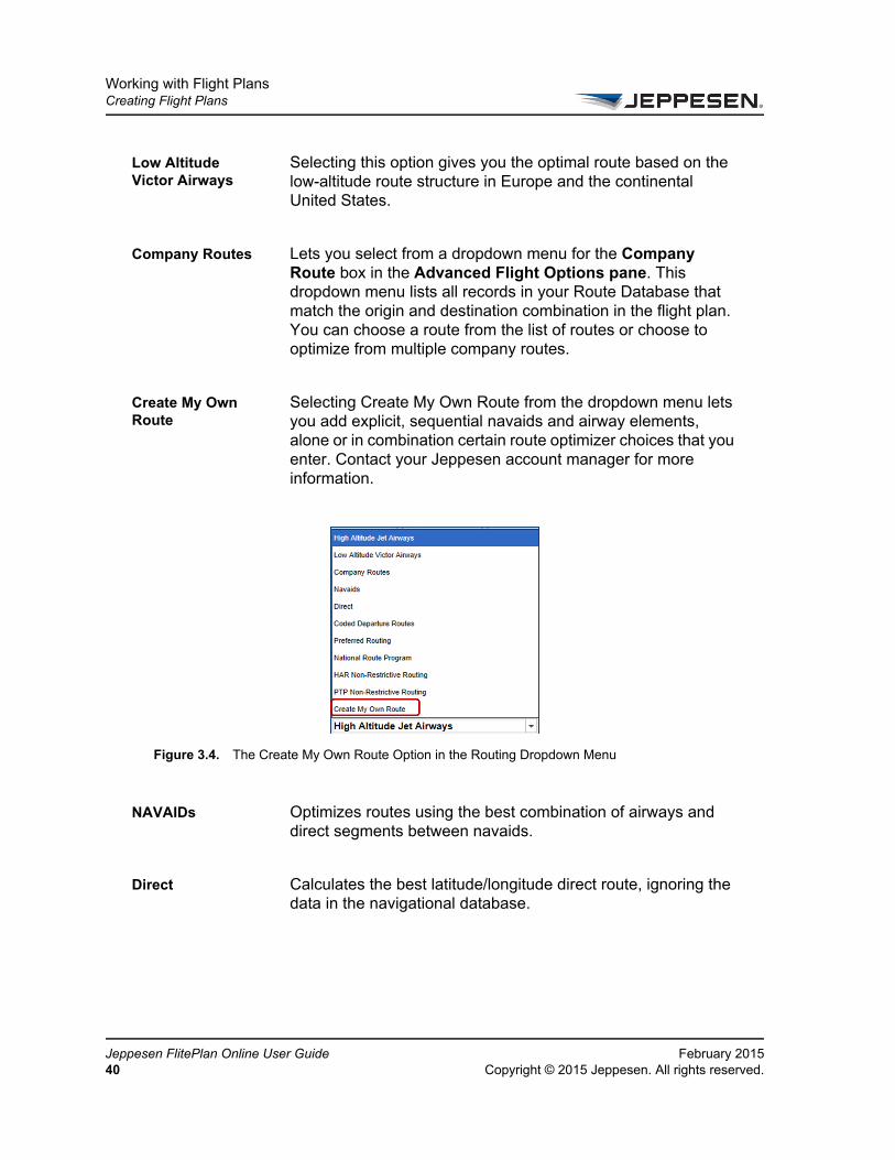
Low Altitude Victor Airways
Selecting this option gives you the optimal route based on the low-altitude route structure in Europe and the continental United States.
Company Routes Lets you select from a dropdown menu for the Company Route box in the Advanced Flight Options pane. This dropdown menu lists all records in your Route Database that match the origin and destination combination in the flight plan. You can choose a route from the list of routes or choose to optimize from multiple company routes.
Create My Own Route
Selecting Create My Own Route from the dropdown menu lets you add explicit, sequential navaids and airway elements, alone or in combination certain route optimizer choices that you enter. Contact your Jeppesen account manager for more information.
NAVAIDs Optimizes routes using the best combination of airways and direct segments between navaids.
Direct Calculates the best latitude/longitude direct route, ignoring the data in the navigational database.
Figure 3.4. The Create My Own Route Option in the Routing Dropdown Menu
ppesen FlitePlan Online User Guide February 2015Copyright © 2015 Jeppesen. All rights reserved.

Working with Flight PlansCreating Flight Plans
FeCo
Coded Departure Routes
Lets you select from a dropdown menu for the Coded Departure Routes (CDRs) box in the Advanced Flight Options pane. This dropdown menu lists all records in the CDR Database that match the origin and destination combination in the flight plan. A CDR must be marked as “OK to Use” in the CDR database before you can use it in a flight plan. This option is only available for routes within the continental U.S.
Preferred Routing Restricts routes to published high-altitude preferred routes where the origin and destination airports are in the U.S. and Canada (Sector 2), or where the origin and destination airports are in Australia (Sector 8).
National Route Program
Allows flights operating at or above FL290 (29,000 ft) within the contiguous U.S. (Sector 2) to participate in minimum time/cost routes without restrictions.
Optimize for EU This option appears when the Origin and Destination airports are in EUROCONTROL airspace. When you select this routing option, Jeppesen Fliteplan Online performs a EUROCONTROL test filing for the purpose of route validation in addition to the flight plan calculation. For more information, see Computing a Flight Plan with EUROCONTROL Test Filing.
Figure 3.5. Sectors
bruary 2015 Jeppesen FlitePlan Online User Guidepyright © 2015 Jeppesen. All rights reserved. 41

Working with Flight PlansCreating Flight Plans
Je42
An airport in EUROCONTROL airspace must be in Sector 1 or Morocco (ICAO code starts with GM) with the following exceptions:
• If the airport is in Iceland (ICAO code starts with BI), Estonia (ICAO code starts with EE), or Greenland (ICAO code starts with BG), it is excluded.
• If the airport ICAO code starts with U, it is excluded unless the following letter is D or K, as in UD (Armenia) or UK (Ukraine). EUROCONTROL airspace includes UD (Armenia) and UK (Ukraine).
HAR Non-Restrictive Routing
Non-Restrictive Routing (NRR) uses an optimized route with Navigational Reference System (NRS) waypoints. NRR allows an adequately-equipped aircraft to fly using Point-To-Point (PTP) navigation above FL390 (39,000 ft). The NRS waypoints define “pitch and catch” gates or entry and exit points for the High Altitude Redesign (HAR) airspace.
A waypoint is generated every 30 minutes of latitude and every two degrees in longitude. Ultimately, the grid system names a waypoint every 10 minutes of latitude and every one degree in longitude and lowers the minimum altitude to FL 290.
The HAR Non-Restrictive Routing option is available when the Origin and Destination airports are both within the continental U.S. (Sector 2). This option assumes that the aircraft has all NRS waypoints in its flight management system (FMS) and is RNAV-equipped. If the aircraft has traditional (not NRS) waypoints in its FMS and is RNAV-equipped, you can select the PTP Non-Restrictive Routing option.
PTP Non-Restrictive Routing
PTP Non-Restrictive Routing uses an NRR optimized route with traditional waypoints. NRR allows an adequately-equipped aircraft to fly using PTP navigation above FL390. The PTP
The NRS Capable (NRS) parameter in the Customer Aircraft Database must be set to Yes for the aircraft to be used in an HAR flight plan that uses the NRS points. If the NRS Capable parameter is set to No, a HARSET01 error is generated when you request the HAR flight plan. Contact your Jeppesen account manager for more information about the NRS Capable (NRS) option in the Customer Aircraft Database.
ppesen FlitePlan Online User Guide February 2015Copyright © 2015 Jeppesen. All rights reserved.
Working with Flight PlansCreating Flight Plans
FeCo
Non-Restrictive Routing option is available when the Origin and Destination airports are both within the continental U.S. (Sector 2). This option assumes that the aircraft has traditional waypoints (not the NRS waypoints) in its FMS and is RNAV-equipped. If the aircraft does have the NRS waypoints in its FMS and is RNAV-equipped, you can select the HAR Non-Restrictive Routing option.
Organized Tracks This option is available when the Origin and Destination airports fall under recommended tracks for those sectors. Available tracks are:
• North Atlantic Tracks (NAT) West
• North Atlantic Tracks (NAT) East
• PACOTS Eastbound
• PACOTS Westbound
• Westbound Flexes
• Eastbound Flexes
• Australian A
• Australian B
• Australian E
You can also choose to request a PTP flight plan for an aircraft that is NRS-capable.
bruary 2015 Jeppesen FlitePlan Online User Guidepyright © 2015 Jeppesen. All rights reserved. 43

Working with Flight PlansCreating Flight Plans
Je44
When the Organized Tracks dropdown menu is available in the Advanced Flight Options pane, the View Details button appears to the right of the dropdown menu. Select this button to view details about the organized track that you select in the dropdown menu.
Create My Own Route
Makes the User Specified box available in the Advanced Flight Options pane. Use this box to enter a Specific Route Selector (SRS) string or optimized routing inputs. This option is always available. For more information, see Advanced Routing Options.
About the Advanced Flight Options PaneUse the Advanced Flight Options pane to specify additional information about flight plans. You enter required flight plan information in the Create New Flight Plan pane, and extra information such as fuel policies, aircraft biases, and avoid areas in the Advanced Flight Options pane.
Select the double arrow button at the top of the Create New Flight Plans pane to bring up the Advanced Flight Options pane.
The Advanced Flight Options pane has the following choices.
• Destination Hold Fuel
• Destination Alternates
• Enroute Alternates
Figure 3.6. Organized Track Details in the Advanced Flight Options Pane
ppesen FlitePlan Online User Guide February 2015Copyright © 2015 Jeppesen. All rights reserved.
Working with Flight PlansCreating Flight Plans
FeCo
• Aircraft Biases
• Aircraft Overrides
• Advanced Arrival Fuel Options
• Fuel Reserve Options
• Route Restriction Options
• Advanced Routing Options
• Advanced Altitude Profile Options
• Selecting Historical Winds as Your Winds Source
• Selecting Statistical Winds as Your Winds Source
• Additional Options on the Advanced Flight Options Pane.
Destination Hold FuelYou can specify a hold time and a hold level for the destination in the Destination area of the Advanced Flight Options pane. When you specify a hold time, an extra fuel amount is added to the total fuel carried. The hold options, not visible until you have entered a destination for the flight plan, are explained below.
Hold Time at Destination
Type the desired hold time (in minutes) to be applied to the destination.
Hold Level at Destination
Type the desired hold level (in feet) above field elevation to be applied to the destination.
Destination AlternatesThe Alternates area in the Advanced Flight Options pane allows you to add additional alternate destination airports and specify details for each alternate. The options for destination alternates are explained below. Some options are not visible until you have entered a destination alternate.
Several of the options below require you to have appropriate permissions to use the information in the JetPlan databases. Contact your Jeppesen account manager for more information.
bruary 2015 Jeppesen FlitePlan Online User Guidepyright © 2015 Jeppesen. All rights reserved. 45

Working with Flight PlansCreating Flight Plans
Je46
Exempt From Specifying Destination Alternates
Remove all options regarding destination alternate airports including any selections you make.
Hold Time at Destination box
Specify a hold time for your first destination alternate airport.
Routing to Alternate
Select the route type you would like to use for each destination alternate. The dropdown menu options are:
• Great Circle – Indicates that a great circle distance should be used when computing the flight plan.
• Distance – Indicates an ad hoc distance to the alternate destination, in nautical miles. Type the distance in the adjacent box.
• Route – Indicates that a customer route should be used when computing the flight plan. A list of routes saved in the JetPlan.com Customer Route Database appears to the right of the route list. Select the route you want to use from the list.
EU-OPS The EU-OPS check box is only available when you specify more than one destination alternate. It includes the corresponding destination alternate in the fuel calculation. If you select more than one destination alternate for EU-OPS, only the alternate that is farthest is included in the fuel calculation. You must have the correct JetPlan permissions to select EU-OPS. Contact your Jeppesen account manager for more information about your permissions.
Add Destination Alternate button
Add another row for entering a destination alternate.
Remove Destination Alternate button
Remove the adjacent destination alternate airport.
ppesen FlitePlan Online User Guide February 2015Copyright © 2015 Jeppesen. All rights reserved.

Working with Flight PlansCreating Flight Plans
FeCo
Enroute Alternate Use this option to indicate an enroute alternate for the flight plan. You must have the correct JetPlan permissions to select an enroute alternate.
Exclude Enroute Alternate (ERA) Calculation
Excludes enroute alternates in the flight plan. If you do not select this check box and you do not specify an enroute alternate, Jeppesen FlitePlan Online automatically calculates an ERA to be included in your flight plan, provided you have the correct JetPlan permissions.
Enroute AlternatesIf your selected aircraft and route meet extended operations (ETOPS) criteria, the Enroute Alternates area is available. Select Include ETOPS to include this analysis. The enroute options are explained below.
Overall Icing Defines the overall icing percentage that is submitted to JetPlan for all ETOPS segments of the flight for calculating fuel requirements.
Origin Displays the airport from which the flight originates.
Use Origin as an ETOPS Alternate
Includes the airport form which the flight originates as an ETOPS alternate in the analysis.
Enroute Alternates The airport designated as an enroute alternate for the flight. Show Commonly Used
Displays a list of commonly used enroute alternate airports based on the route.
Airport Suitability Indicator
A green, yellow, or grey status bar appears above each enroute alternate:
• Select the green status bar to view the TAF for that airport.
bruary 2015 Jeppesen FlitePlan Online User Guidepyright © 2015 Jeppesen. All rights reserved. 47
Working with Flight PlansCreating Flight Plans
Je48
• A yellow status bar indicates that the weather is VFR marginal, or that a TAF for that airport is not currently available. Select the yellow status bar to view either the TAF or “TAF unavailable” message.
• A grey bar indicates that an enroute alternate has not been entered.
Destination Displays the destination airport.
Use Destination as an ETOPS Alternate
Include the destination airport as an ETOPS alternate in the analysis.
Aircraft Biases Use aircraft biases to apply ad hoc biases with one or more unique parameters. An ad hoc bias is applied in the unit and number amount that you specify. For example, if you type 1.25 and select% as the unit, the bias increases the value by 1.25 percent. You must precede negative values with a minus sign. For example, if you type – 1.25 and select nm as the unit, the bias decreases the value by 1.25 nm.
Departure aircraft biases apply only to the departure segment of the flight, and are entered as positive whole numbers. The types of departure aircraft biases are explained below.
Departure Distance
Use this bias to add mileage to the flight plan by the amount you enter. This bias does not affect the climb profile.
Departure Fuel Use this bias to increase the fuel totals for the climb portion of the flight by the amount you enter, as well as the amount required to carry extra fuel. For example, a departure bias of 1,000 lbs may require an additional 30 lbs to carry it to the Top of Climb (TOC).
Departure Time Use this bias to add time to the climb table time. Time is also added to the cruise and descent time totals.
ppesen FlitePlan Online User Guide February 2015Copyright © 2015 Jeppesen. All rights reserved.

Working with Flight PlansCreating Flight Plans
FeCo
Arrival aircraft biases apply only to the arrival segment of the flight, and are entered as positive whole numbers. The types of arrival aircraft biases are explained below.
Arrival Distance Use this bias to add mileage to the flight plan by the amount you enter. This bias does not affect the descent profile.
Arrival Fuel Use this bias to increase the fuel totals for the arrival portion of the flight by the amount you enter, as well as the amount required to carry extra fuel. For example, an arrival bias of 1,000 lbs requires extra fuel during the enroute cruise portion of the flight.
Arrival Time Use this bias to add time to the descent table time. Time is also added to the climb and cruise time totals.
Alternate aircraft biases apply to the primary destination alternate and you must enter them as whole numbers, positive or negative. The types of alternate aircraft biases are explained below.
Alternate Distance Add or subtract from the alternate distance.
Alternate Fuel Add or subtract from the alternate fuel.
Alternate Time Add or subtract from the alternate time.
Cruise aircraft biases apply to the Primary Cruise Mode, and you must enter them as percentages or whole numbers, positive or negative. The types of cruise aircraft biases are explained below.
Cruise True Air Speed
Add or subtract True Air Speed for the Primary Cruise Mode.
Cruise Fuel Flow Add or subtract fuel flow from the Primary Cruise Mode.
bruary 2015 Jeppesen FlitePlan Online User Guidepyright © 2015 Jeppesen. All rights reserved. 49
Working with Flight PlansCreating Flight Plans
Je50
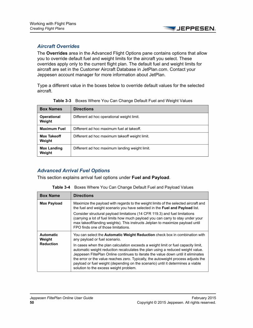
Aircraft OverridesThe Overrides area in the Advanced Flight Options pane contains options that allow you to override default fuel and weight limits for the aircraft you select. These overrides apply only to the current flight plan. The default fuel and weight limits for aircraft are set in the Customer Aircraft Database in JetPlan.com. Contact your Jeppesen account manager for more information about JetPlan.
Type a different value in the boxes below to override default values for the selected aircraft.
Advanced Arrival Fuel Options This section explains arrival fuel options under Fuel and Payload.
Table 3-3 Boxes Where You Can Change Default Fuel and Weight Values
Box Names Directions
Operational Weight
Different ad hoc operational weight limit.
Maximum Fuel Different ad hoc maximum fuel at takeoff.
Max Takeoff Weight
Different ad hoc maximum takeoff weight limit.
Max Landing Weight
Different ad hoc maximum landing weight limit.
Table 3-4 Boxes Where You Can Change Default Fuel and Payload Values
Box Name Directions
Max Payload Maximize the payload with regards to the weight limits of the selected aircraft and the fuel and weight scenario you have selected in the Fuel and Payload list.
Consider structural payload limitations (14 CFR 119.3) and fuel limitations (carrying a lot of fuel limits how much payload you can carry to stay under your max takeoff/landing weights). This instructs Jetplan to maximize payload until FPO finds one of those limitations.
Automatic Weight Reduction
You can select the Automatic Weight Reduction check box in combination with any payload or fuel scenario.
In cases when the plan calculation exceeds a weight limit or fuel capacity limit, automatic weight reduction recalculates the plan using a reduced weight value. Jeppesen FlitePlan Online continues to iterate the value down until it eliminates the error or the value reaches zero. Typically, the autoweight process adjusts the payload or fuel weight (depending on the scenario) until it determines a viable solution to the excess weight problem.
ppesen FlitePlan Online User Guide February 2015Copyright © 2015 Jeppesen. All rights reserved.
Working with Flight PlansCreating Flight Plans
FeCo
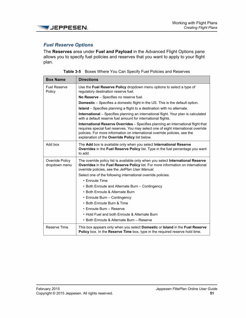
Fuel Reserve OptionsThe Reserves area under Fuel and Payload in the Advanced Flight Options pane allows you to specify fuel policies and reserves that you want to apply to your flight plan.
Table 3-5 Boxes Where You Can Specify Fuel Policies and Reserves
Box Name Directions
Fuel Reserve Policy
Use the Fuel Reserve Policy dropdown menu options to select a type of regulatory destination reserve fuel.
No Reserve – Specifies no reserve fuel.
Domestic – Specifies a domestic flight in the US. This is the default option.
Island – Specifies planning a flight to a destination with no alternate.
International – Specifies planning an international flight. Your plan is calculated with a default reserve fuel amount for international flights.
International Reserve Overrides – Specifies planning an international flight that requires special fuel reserves. You may select one of eight international override policies. For more information on international override policies, see the explanation of the Override Policy list below.
Add box The Add box is available only when you select International Reserve Overrides in the Fuel Reserve Policy list. Type in the fuel percentage you want to add.
Override Policy dropdown menu
The override policy list is available only when you select International Reserve Overrides in the Fuel Reserve Policy list. For more information on international override policies, see the JetPlan User Manual.
Select one of the following international override policies:
• Enroute Time
• Both Enroute and Alternate Burn – Contingency
• Both Enroute & Alternate Burn
• Enroute Burn – Contingency
• Both Enroute Burn & Time
• Enroute Burn – Reserve
• Hold Fuel and both Enroute & Alternate Burn
• Both Enroute & Alternate Burn – Reserve
Reserve Time This box appears only when you select Domestic or Island in the Fuel Reserve Policy box. In the Reserve Time box, type in the required reserve hold time.
bruary 2015 Jeppesen FlitePlan Online User Guidepyright © 2015 Jeppesen. All rights reserved. 51

Working with Flight PlansCreating Flight Plans
Je52
Route Restriction OptionsUse the Route Restrictions area under Routing on the Advanced Flight Options pane to restrict your flight path from crossing specified checkpoints, FIRs/UIRs, and airways. Each of these options is explained below.
Special Reserves Specify any Fuel Over Destination requirements. Select one of the following options:
• None Specified – This is the default option. No additional fuel is specified for the flight plan.
• Fuel Over Destination – Ensures that a specific amount of fuel is available at landing. If the sum of the hold, alternate, reserve, and requested extra fuels (contingency fuels) is less than the specified Minimum Fuel Over Destination value, extra fuel is added. This option generates an error if the sum of these fuels exceeds the Fuel Over Destination value. This option sets the exact amount of contingency fuel this flight must have.
• Minimum Fuel Over Destination – This option is similar to the Fuel Over Destination option. It ensures a minimum value for Fuel Over Destination if the sum of the hold, alternate, reserve, and contingency fuels does not meet your requirements. However, there may be excess contingency fuel with this option.
Fuel This box appears only when you select Fuel Over Destination or Minimum Fuel Over Destination in the Special Reserves list.
Table 3-6 Route Restriction Options
Box Name Directions
Avoid Checkpoints
To prevent your flight path from crossing a particular checkpoint, type the checkpoint identifier in one of the Avoid Checkpoints boxes. If you want to specify more than five checkpoints to avoid, select the adjacent add (+) button.You may specify as many as 20 checkpoints to avoid.
Avoid FIRs/UIRs To prevent your flight path from crossing a particular FIR or UIR, type the identifier for the boundary in one of the Avoid FIRs/UIRs boxes. If you want to specify more than five FIRs and UIRs, select the adjacent add (+) button. You may specify as many as 10 FIRs and UIRs to avoid.
Table 3-5 Boxes Where You Can Specify Fuel Policies and Reserves
Box Name Directions
ppesen FlitePlan Online User Guide February 2015Copyright © 2015 Jeppesen. All rights reserved.

Working with Flight PlansCreating Flight Plans
FeCo
Advanced Routing OptionsThis section explains the options under Routing on the Advanced Flight Options pane, excluding the Route Restrictions area. For information on specifying route restrictions, see Route Restriction Options. The first few options explained below only appear when certain route types are selected on the Create New Flight Plan pane.
Avoid Airways To prevent your flight path from crossing a particular airway, type the name of the airway in the Avoid Airways box. You specify a segment of the airway to avoid using the Checkpoints Start and Checkpoints End boxes, explained below. If you want to specify more than one airway to avoid, select the adjacent add (+) button. You may specify as many as 10 airways to avoid.
Avoiding an airway requires you to define the airway segment explicitly by specifying the airway name, and then denoting a starting and ending checkpoint for the segment of the airway you wish to bypass. The starting and ending point identifiers are simply valid checkpoints on the airway.
Checkpoints Start
If you have specified an airway to avoid, use the Checkpoints Start box to type a beginning checkpoint on the segment of the airway you want to bypass.
Checkpoints End
If you have specified an airway to avoid, use the Checkpoints End box to type a ending checkpoint on the segment of the airway you want to bypass.
Avoid User-defined
Use the Avoid User-defined list to specify an ad hoc area to avoid. You may specify a circular area to avoid, or a polygonal area with up to five sides. To avoid a circular area, you must specify a center point of the circle and a radius. To avoid a polygonal area, you must specify each corner point of the area.
Latitude If you are creating a circular avoid area, use the Latitude boxes to type the latitude point for the center of the circle. If you are creating a polygonal avoid area, use the Latitude boxes to type the latitude points for each corner of the polygon.
Longitude If you are creating a circular avoid area, use the Longitude boxes to type the longitude point for the center of the circle. If you are creating a polygonal avoid area, use the Longitude boxes to type the longitude points for each corner of the polygon.
Radius The Radius box is only available if you are creating a circular user-defined avoid area. Use the Radius box to type the radius of the area in nm.
Table 3-7 Advanced Routing Options for Certain Route Types
Box Name Directions
Coded Departure Routes
See Routing Options in the Create New Flight Plan Pane.
Table 3-6 Route Restriction Options
Box Name Directions
bruary 2015 Jeppesen FlitePlan Online User Guidepyright © 2015 Jeppesen. All rights reserved. 53

Working with Flight PlansCreating Flight Plans
Je54
User Specified The User Specified box appears when you select Create My Own Route in the Routing dropdown menu on the Create New Flight Plan pane. Enter a Specific Route Selector (SRS) string or optimized routing inputs. See the “Route Commands” section in the JetPlan User Manual for information on routing syntax.
Company Routes dropdown menu options
The Company Routes menu options appear when you select Company Routes in the Routing box in the Create New Flight Plan pane. You must have customer routes stored in the Customer Routes Database.
Time Restricted Airways option
Specify how the system factors in time restricted airways along the route. Choose from the following:
Do Not Use – All time restricted airways are avoided, whether they are open or closed. This option is the default setting.
Use and Adhere to Restrictions – All time restricted airways that are open are considered.
Use and Ignore Restrictions – All time restricted airways are considered, whether they are currently open or closed.
CRAM Consider CRAM processing and give the system access to CDR1 / CDR2 CRAM routes as published by EUROCONTROL. The CRAM check box is selected by default if Optimized for EU has been selected as the routing option.
ERAD Enable EUROCONTROL Route Availability Document (ERAD) routing, allowing the system to create a route that is both optimized and compliant with EUROCONTROL’s traffic flow restrictions. Jeppesen recommends that you select the ERAD check box when performing a EUROCONTROL test file validation, unless you have selected Optimized for EU as the routing option. (If Optimized for EU is selected as the routing option, the ERAD check box is selected by default but disabled.)
These options increase your likelihood of passing the test file validation. For more information, see Test Filing with EUROCONTROL.
TACAN Routing Includes TACAN routing in the calculations.
MEA/MAA Consider and maintain a profile constraint based on MEA/MMA factors.
MAA (Maximum Authorized Altitude) is the maximum altitude at which you can be certain the VOR stations on the same frequency do not interfere with each other. MEA (Minimum Enroute Altitude) is the minimum altitude at which you can receive reliable VOR signals along a specific segment of an airway. MEAs also assure adequate clearance (1000 feet) of any obstacle (2000 feet in the mountains) within 5 NM of the airway center line.
Grid MORA GRID MORA (Minimum Off Route Altitude) is a Jeppesen method of depicting the minimum flight altitude within a grid formed by the charted lines of latitude and longitude. Select GRID MORA if routing deviates from airway structure and you want to maintain minimum flight altitudes.
Table 3-7 Advanced Routing Options for Certain Route Types
Box Name Directions
ppesen FlitePlan Online User Guide February 2015Copyright © 2015 Jeppesen. All rights reserved.
Working with Flight PlansCreating Flight Plans
FeCo
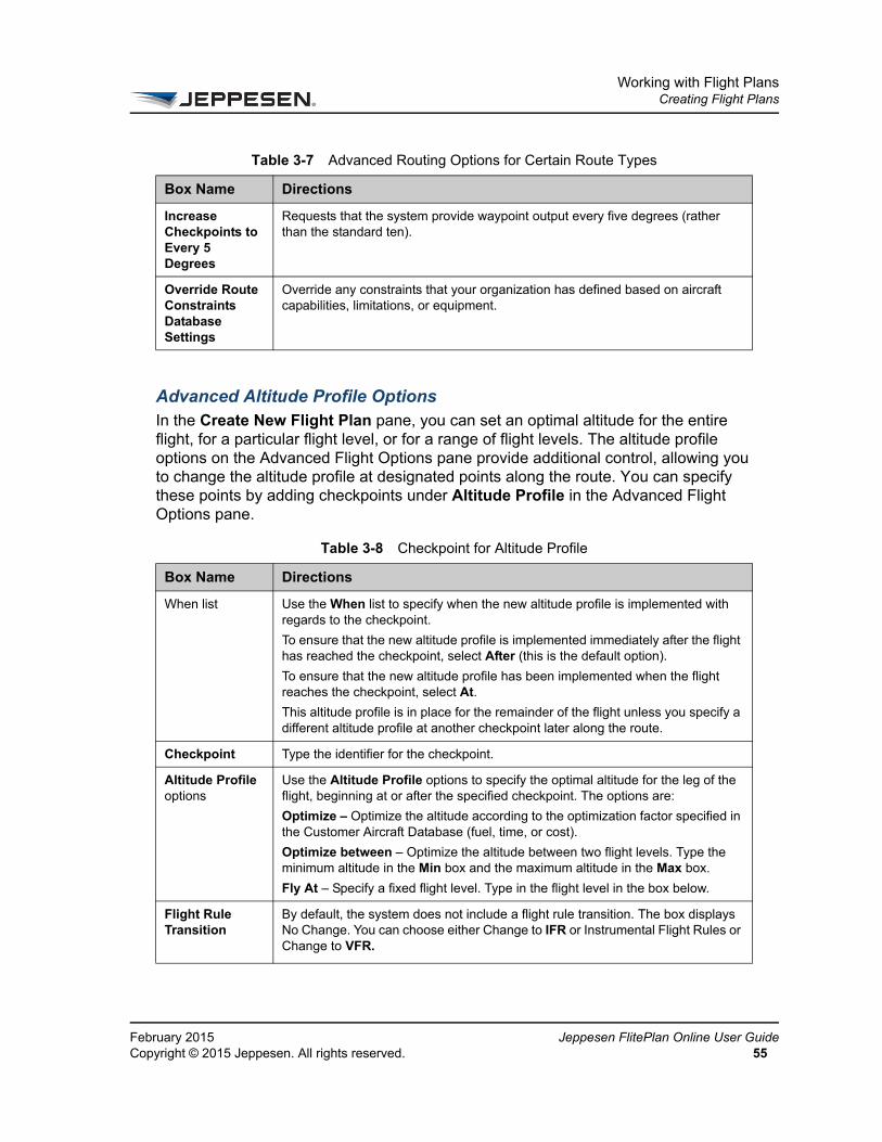
Advanced Altitude Profile OptionsIn the Create New Flight Plan pane, you can set an optimal altitude for the entire flight, for a particular flight level, or for a range of flight levels. The altitude profile options on the Advanced Flight Options pane provide additional control, allowing you to change the altitude profile at designated points along the route. You can specify these points by adding checkpoints under Altitude Profile in the Advanced Flight Options pane.
Increase Checkpoints to Every 5 Degrees
Requests that the system provide waypoint output every five degrees (rather than the standard ten).
Override Route Constraints Database Settings
Override any constraints that your organization has defined based on aircraft capabilities, limitations, or equipment.
Table 3-8 Checkpoint for Altitude Profile
Box Name Directions
When list Use the When list to specify when the new altitude profile is implemented with regards to the checkpoint.
To ensure that the new altitude profile is implemented immediately after the flight has reached the checkpoint, select After (this is the default option).
To ensure that the new altitude profile has been implemented when the flight reaches the checkpoint, select At.
This altitude profile is in place for the remainder of the flight unless you specify a different altitude profile at another checkpoint later along the route.
Checkpoint Type the identifier for the checkpoint.
Altitude Profile options
Use the Altitude Profile options to specify the optimal altitude for the leg of the flight, beginning at or after the specified checkpoint. The options are:
Optimize – Optimize the altitude according to the optimization factor specified in the Customer Aircraft Database (fuel, time, or cost).
Optimize between – Optimize the altitude between two flight levels. Type the minimum altitude in the Min box and the maximum altitude in the Max box.
Fly At – Specify a fixed flight level. Type in the flight level in the box below.
Flight Rule Transition
By default, the system does not include a flight rule transition. The box displays No Change. You can choose either Change to IFR or Instrumental Flight Rules or Change to VFR.
Table 3-7 Advanced Routing Options for Certain Route Types
Box Name Directions
bruary 2015 Jeppesen FlitePlan Online User Guidepyright © 2015 Jeppesen. All rights reserved. 55
Working with Flight PlansCreating Flight Plans
Je56
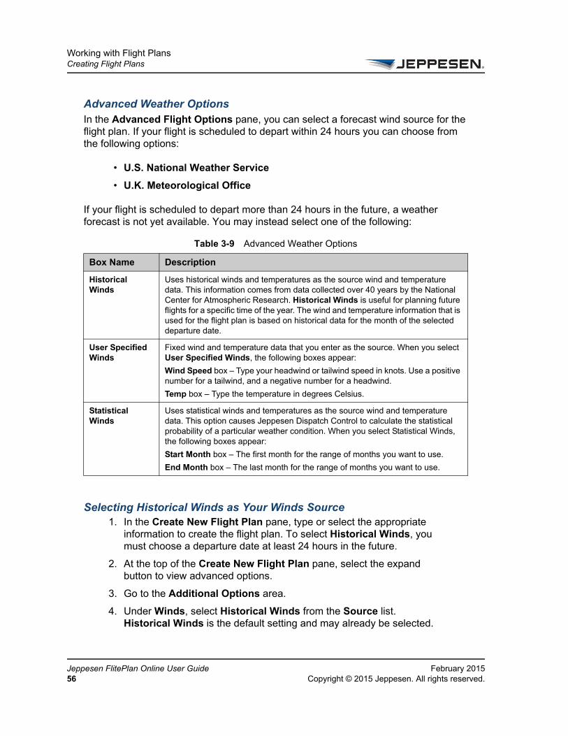
Advanced Weather OptionsIn the Advanced Flight Options pane, you can select a forecast wind source for the flight plan. If your flight is scheduled to depart within 24 hours you can choose from the following options:
• U.S. National Weather Service
• U.K. Meteorological Office
If your flight is scheduled to depart more than 24 hours in the future, a weather forecast is not yet available. You may instead select one of the following:
Selecting Historical Winds as Your Winds Source1. In the Create New Flight Plan pane, type or select the appropriate
information to create the flight plan. To select Historical Winds, you must choose a departure date at least 24 hours in the future.
2. At the top of the Create New Flight Plan pane, select the expand button to view advanced options.
3. Go to the Additional Options area.
4. Under Winds, select Historical Winds from the Source list. Historical Winds is the default setting and may already be selected.
Table 3-9 Advanced Weather Options
Box Name Description
Historical Winds
Uses historical winds and temperatures as the source wind and temperature data. This information comes from data collected over 40 years by the National Center for Atmospheric Research. Historical Winds is useful for planning future flights for a specific time of the year. The wind and temperature information that is used for the flight plan is based on historical data for the month of the selected departure date.
User Specified Winds
Fixed wind and temperature data that you enter as the source. When you select User Specified Winds, the following boxes appear:
Wind Speed box – Type your headwind or tailwind speed in knots. Use a positive number for a tailwind, and a negative number for a headwind.
Temp box – Type the temperature in degrees Celsius.
Statistical Winds
Uses statistical winds and temperatures as the source wind and temperature data. This option causes Jeppesen Dispatch Control to calculate the statistical probability of a particular weather condition. When you select Statistical Winds, the following boxes appear:
Start Month box – The first month for the range of months you want to use.
End Month box – The last month for the range of months you want to use.
ppesen FlitePlan Online User Guide February 2015Copyright © 2015 Jeppesen. All rights reserved.

Working with Flight PlansCreating Flight Plans
FeCo
Selecting User Specified Winds as Your Winds Source1. In the Create New Flight Plan pane, type or select the appropriate
information to create the flight plan. To select User Specified Winds, you must choose a departure date at least 24 hours in the future.
2. At the top of the Create New Flight Plan pane, select the expand button to view advanced options.
3. Go to the Additional Options area.
4. Under Winds, select User Specified from the Source list.
The Wind Speed and Temperature boxes appear below.
• In the Wind Speed box, type your headwind or tailwind speed in knots. Use a positive number for a tailwind, and a negative number for a headwind.
• In the Temp box, type the fixed temperature in degrees Celsius.
Selecting Statistical Winds as Your Winds Source1. In the Create New Flight Plan pane, type or select the appropriate
information to create the flight plan. To select User Specified Winds, you must choose a departure date at least 24 hours in the future.
2. At the top of the Create New Flight Plan pane, select the expand button to view advanced options.
3. Go to the Additional Options area.
4. Under Winds, select Statistical Winds from the Source list.
The Start Month and End Month boxes appear below.
• In the Start Month box, select the first month for the range of months you want to use.
• In the End Month box, select the first month for the range of months you want to use.
bruary 2015 Jeppesen FlitePlan Online User Guidepyright © 2015 Jeppesen. All rights reserved. 57
Working with Flight PlansCreating Flight Plans
Je58
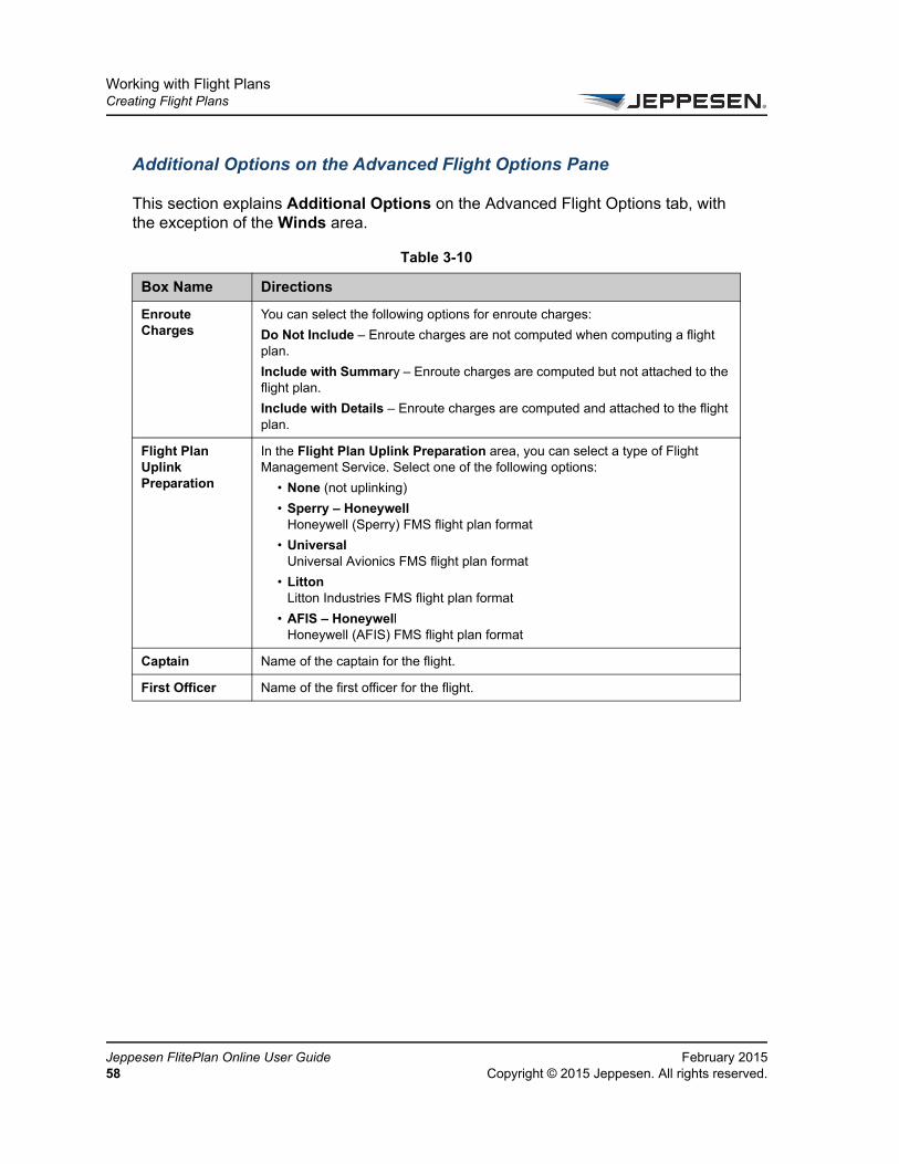
Additional Options on the Advanced Flight Options Pane
This section explains Additional Options on the Advanced Flight Options tab, with the exception of the Winds area.
Table 3-10
Box Name Directions
Enroute Charges
You can select the following options for enroute charges:
Do Not Include – Enroute charges are not computed when computing a flight plan.
Include with Summary – Enroute charges are computed but not attached to the flight plan.
Include with Details – Enroute charges are computed and attached to the flight plan.
Flight Plan Uplink Preparation
In the Flight Plan Uplink Preparation area, you can select a type of Flight Management Service. Select one of the following options:
• None (not uplinking)
• Sperry – HoneywellHoneywell (Sperry) FMS flight plan format
• UniversalUniversal Avionics FMS flight plan format
• Litton Litton Industries FMS flight plan format
• AFIS – Honeywell Honeywell (AFIS) FMS flight plan format
Captain Name of the captain for the flight.
First Officer Name of the first officer for the flight.
ppesen FlitePlan Online User Guide February 2015Copyright © 2015 Jeppesen. All rights reserved.
Working with Flight PlansCreating Flight Plans
FeCo
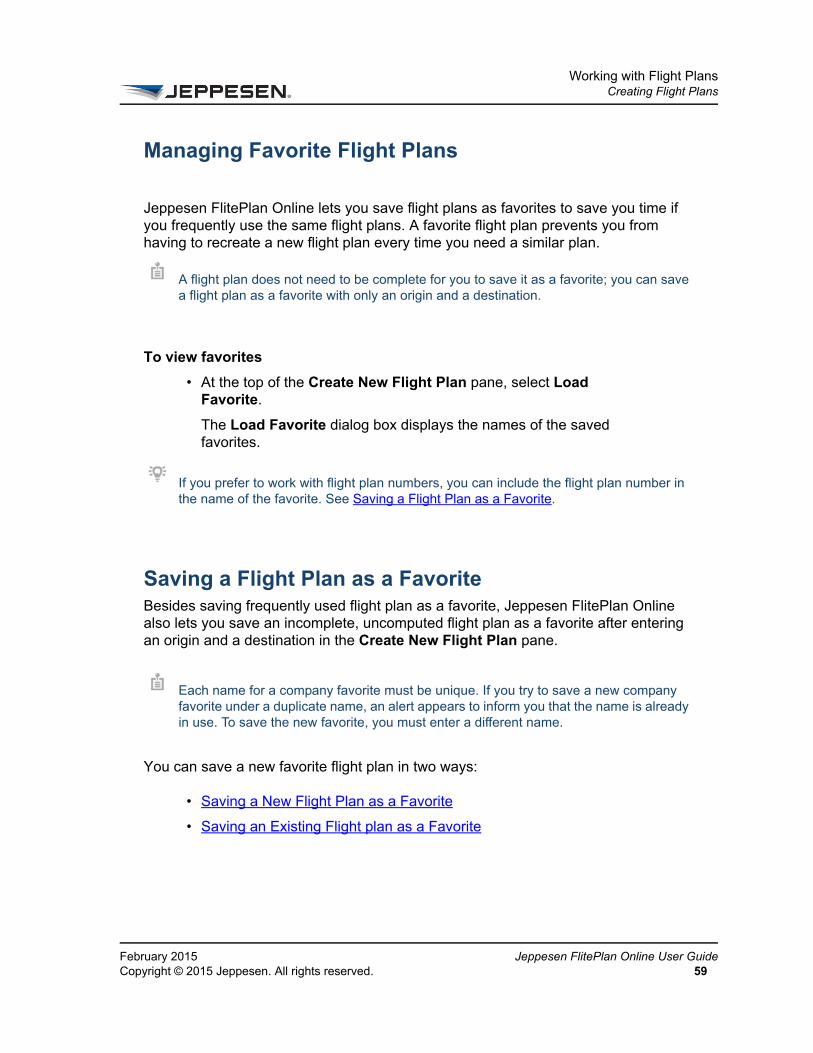
Managing Favorite Flight Plans
Jeppesen FlitePlan Online lets you save flight plans as favorites to save you time if you frequently use the same flight plans. A favorite flight plan prevents you from having to recreate a new flight plan every time you need a similar plan.
To view favorites
• At the top of the Create New Flight Plan pane, select Load Favorite.
The Load Favorite dialog box displays the names of the saved favorites.
Saving a Flight Plan as a FavoriteBesides saving frequently used flight plan as a favorite, Jeppesen FlitePlan Online also lets you save an incomplete, uncomputed flight plan as a favorite after entering an origin and a destination in the Create New Flight Plan pane.
You can save a new favorite flight plan in two ways:
• Saving a New Flight Plan as a Favorite
• Saving an Existing Flight plan as a Favorite
A flight plan does not need to be complete for you to save it as a favorite; you can save a flight plan as a favorite with only an origin and a destination.
If you prefer to work with flight plan numbers, you can include the flight plan number in the name of the favorite. See Saving a Flight Plan as a Favorite.
Each name for a company favorite must be unique. If you try to save a new company favorite under a duplicate name, an alert appears to inform you that the name is already in use. To save the new favorite, you must enter a different name.
bruary 2015 Jeppesen FlitePlan Online User Guidepyright © 2015 Jeppesen. All rights reserved. 59
Working with Flight PlansCreating Flight Plans
Je60
Saving a New Flight Plan as a Favorite
Use the procedure below to save a new flight plan as a favorite or copying a favorite to create a new favorite.
1. On the Create New Flight Plan pane, type or select the appropriate information to create the flight plan. See Create a Flight Plan with New Values.
2. When you have entered the information for the flight plan, select Save Favorite.
3. In the Save Favorite dialog box, type a name for the favorite.
4. Select Save.
5. In the Favorite Created message, select OK.
Saving an Existing Flight plan as a Favorite1. Select the Flight Plans navigation tab.
2. From the Active or History pane, select the flight plan.
3. Select Recompute.
4. In the Recompute dialog box, select either Use Existing Route or Get New Route.
5. Select Submit.
The flight plan loads in the Create New Flight Plan pane.
6. At the bottom of the Create New Flight Plan pane, select Save Favorite.
7. In the Save Favorite dialog box, type a name for the favorite.
8. Select Save.
9. In the Favorite Created message, select OK.
Reusing a Favorite Flight PlanWhen reusing a favorite flight plan, you must first load the favorite in the Create New Flight Plan pane. If the favorite plan is complete (all required values are included), you only need to enter a departure time and date before calculating the plan. You can also edit some of the other values of a favorite before you reuse it.
ppesen FlitePlan Online User Guide February 2015Copyright © 2015 Jeppesen. All rights reserved.
Working with Flight PlansCreating Flight Plans
FeCo
To reuse a favorite flight plan
1. In the Create New Flight Plan pane, check that no values appear. If values do appear, select Clear.
2. Select Load Favorite.
3. In the Load Favorite dialog box, select the name of the favorite that you want to reuse.
4. Select Load Selected.
The favorite flight plan loads in the Create New Flight Plan pane.
5. Enter the departure time and date for the flight in the Time and Departure Date boxes.
6. Enter any other changes you may want to make to the flight plan if you want to modify it.
7. Select Create Plan.
The favorite you are reusing appears in the Active pane with a new flight number.
Updating a Favorite Flight Plan1. In the Create New Flight Plan pane, check that no values appear. If
values do appear, select Clear.
2. Select Load Favorite.
3. In the Load Favorite dialog box, select the name of the favorite that you want to update.
4. Select Load Selected.
The favorite flight plan loads in the Create New Flight Plan pane.
5. Make your changes to the flight plan.
6. Select Update [Plan Name] at the top of the Create New Flight Plan pane.
7. In the Favorite Created message, select OK.
bruary 2015 Jeppesen FlitePlan Online User Guidepyright © 2015 Jeppesen. All rights reserved. 61

Working with Flight PlansCreating Flight Plans
Je62
Sorting Favorite Flight PlansFavorite flight plans are listed in the Load Favorites dialog box in the order they were created, with the most recently created favorites listed at the top.
• Select the column headings to sort favorites.
Deleting Favorite Flight Plans1. In the Create New Flight Plan pane, select Load Favorite.
2. In the Load Favorite dialog box, do one of the following:
• To delete a single flight plan, select the minus (–) sign next to the favorite that you want to delete.
• To remove multiple flight plans, hold down the CTRL key and select each favorite to be deleted.
• Select Remove Selected.
Table 3-11 Sorting Favorites by Column Headings
Column Heading Sort Description
Name Sorts favorites in alphabetical order by name.
Origin Sorts favorites in alphabetical order by the ICAO code of the origin.
Destination Sorts favorites in alphabetical order by the ICAO code of the destination.
Aircraft Sorts favorites in numerical and alphabetical order by the name of the aircraft.
ppesen FlitePlan Online User Guide February 2015Copyright © 2015 Jeppesen. All rights reserved.

Working with Flight PlansManaging Flight Plan Packages
FeCo
Managing Flight Plan PackagesA flight plan package is a combination of information, reports, and statuses related to a computed flight plan. It is updated when you request items related to that flight plan, or when the system receives an updated status from external systems, such as Air Traffic Control (ATC).
The flight plan package allows you to:
• View reports, such as RAIM prediction and Weight and Balance, and other information related to the flight plan. The flight plan package can be used as a checklist.
• Generate, save, and send reports related to the flight.
• Change the filing status of a flight plan.
• View filing history.
• Create a load plan from the flight plan package.
The following sections explain more about viewing flight plans and managing flight plan packages:
• Viewing Flight Plans
• Viewing a Flight Plan Package
• Creating a Load Plan from the Flight Plan Package
• Generating and Updating Reports in the Flight Plan Package
• To update or generate airport details in the flight package
• Adding Map Captures to a Flight Plan Package
• Creating a PDF from a Flight Plan Package
• Printing a Flight Plan Package
If you have a customized flight plan format, you do not see the flight plan as described here. However, if you use a default format, this information appears based on your selected options and other information.
bruary 2015 Jeppesen FlitePlan Online User Guidepyright © 2015 Jeppesen. All rights reserved. 63

Working with Flight PlansViewing Flight Plans
Je64
Viewing Flight PlansAfter your flight plan is computed, a summary view of the flight plan appears in the Active pane when you select the Flight Plans navigation tab. A graphic representation of the flight route appears on the Map tab.
Jeppesen FlitePlan Online maintains a list of computed flight plans, which appears as a table in the Active and History panes. Flight plans are sorted in descending order by date and time computed, with the most recent shown first. See The Active and History Panes.
The table columns on the Flight Plans navigation tab are explained below.
To view a flight plan summary
1. On the navigation bar, select Flight Plans.
2. In the Active or History pane, select a flight plan.
3. Select View Package.
The Flight Plan Summary opens with the filing status displayed below the Airport tab. A brief summary of the flight plan appears at the top of the pane. The summary contains the following information (by row):
Table 3-12
Column Heading Description
Origin The four-character ICAO code of the departure location.
Destination The four-character ICAO code of the planned destination.
Departure (UTC) The planned date and time of departure.
Enroute The estimated time enroute.
Fuel Burn The estimated fuel (in pounds) required to complete the flight.
Speed The selected cruise mode used for the computed flight plan.
FLV Flight Level, specifically the maximum altitude achieved during the flight.
Distance Total distance to be flown.
Aircraft Name of aircraft used in the flight.
Type Type of aircraft used in the flight.
Route Selected route for the flight.
ppesen FlitePlan Online User Guide February 2015Copyright © 2015 Jeppesen. All rights reserved.
Working with Flight PlansViewing Flight Plans
FeCo
• ETE
• Distance
• Aircraft
– Type Fuel Burn
– Cruise Speed
• Flight Level
– Route
– EUROCONTROL test file validation status, if applicable (for more information, see Test Filing with EUROCONTROL).
To view a flight plan
1. On the navigation bar, select Flight Plans.
2. In the Active or History pane, select the flight plan you want to view.
3. Select View Package in the Active or History pane to see details of the flight plan.
Viewing a Flight Plan Package
The flight plan package is divided into two areas. The area at the left on the window contains a list of the reports that you may include in the flight plan package. Some of the reports may be unavailable, indicating that a report of that type has not been successfully generated for the selected flight. Some of the report types may include the option to generate a new report or update an existing report.
bruary 2015 Jeppesen FlitePlan Online User Guidepyright © 2015 Jeppesen. All rights reserved. 65

Working with Flight PlansViewing Flight Plans
Je66
The area at the right on the window contains all the reports that you have chosen to include in the flight plan package. This area also includes a status bar with options to change the filing status of the selected flight; refresh the ATC filing status; or send, save, or print the flight plan package. The reports on the flight plan package are explained below.
You can view flight plan package information based on your flight plan display configurations.
To view a flight plan (default configurations)
1. On the navigation bar, select Flight Plans.
2. Select the desired flight plan from either the Active or History pane.
A summary of the flight plan appears at the top of the selected pane.
3. At the bottom of the flight plan summary, select View Package.
The flight plan package appears.
4. In the area at the left, select the check boxes for the reports that you want included in the flight plan package.
Depending on the reports you have selected, the Flight Plan Summary area at the right may include the following:
• Status bar
Figure 3.7. Viewing a Flight Plan Package with Weight and Balance Highlighted
The reports listed below are user-generated, not initiated by the system.
ppesen FlitePlan Online User Guide February 2015Copyright © 2015 Jeppesen. All rights reserved.
Working with Flight PlansViewing Flight Plans
FeCo
• Flight Plan Summary area
• Alerts
• View Full Plan
• Filing History
• Wx (Airports Only)
• ETOPS Extended Information
• Enroute Information
• METAR(s)
• TAFs
• PIREPs
• Winds Aloft
• AIRMETs
• SIGMETs
• Convective SIGMETs
• Center Weather Advisory
• Severe Weather Advisory
• Hurricane Bulletin
• Volcanic Ash Advisory
• Area Forecast
• City Forecast
• Recreation Forecast
• Airports & Diagrams
• Runways
• Handlers
• Hotels
• Caterers
• Transportation Companies
• Enroute Corridor
• NOTAMs/TFRs area
• RAIM Report area
bruary 2015 Jeppesen FlitePlan Online User Guidepyright © 2015 Jeppesen. All rights reserved. 67

Working with Flight PlansViewing Flight Plans
Je68
• RAIM Predication Parameters
• Arrival Alternate Corridor
• Other Alternate Areas
• Origin
• Arrival Alternate
• Takeoff Alternate
• Airports area
• RAIM Report area
• Weight and Balance area
• Map Captures area
For more information on the areas listed above, see Printing a Flight Plan Package.
5. When you have finished viewing the flight plan package, select Close.
Creating a Load Plan from the Flight Plan PackageYou can create a load plan from the flight plan package as well.
About the NOTAMs/TFRs FilterJeppesen FlitePlan Online automatically filters NOTAMs and TFRs for relevancy in the flight plan package, so that you see only those NOTAMs/TFRs that pertain to your flight. NOTAMs are shown in the ICAO format.
The following filtration criteria are applied:
• Only NOTAMs that are effective 90 Minutes prior to ETD through 90 minutes after ETA are included and the following NOTAM types are filtered out:
– JC (Jeppesen Chart)
– JN (Jeppesen NavData)
– NP (Jeppesen Publication NOTAMs)
ppesen FlitePlan Online User Guide February 2015Copyright © 2015 Jeppesen. All rights reserved.
Working with Flight PlansViewing Flight Plans
FeCo
• NOTAMs are filtered based on their Q-Code and the “phase of flight” in which they occur.
The following Q-codes are filtered out for the “Terminal” phase of flight filter:
– Characters 2-3: CE, NA, NB, NC, NO, NX, AD, AF, AH, AL, AN, AO, AR, AU, AV, SC, SE, SL, SO, SS, SU, SV, SY, PZ, RA, RD, RM, RP, WE, WF, WM, WR, WS, WT, WW, GW
– Characters 4-5: None
The following Q-codes are filtered out for the “Enroute” phase of flight filter:
– Characters 2-3: LA, LB, LC, LD, LE, LF, LG, LH, LI, LJ, LK, LL, LM, LP, LR, LS, LT, LU, LV, LW, LX, LY, LZ, MA, MB, MC, MD, M MG, MH, MK, MM, MN, MO, MP, MR, MS, MT, MU, MW, MX, MY, OB, OL, FA, FB, FC, FD, FE, FF, FG, FH, FI, FJ, FL, FM, FO, FP FS, FT, FU, FW, FZ, CG, CM, CP, CR, CT, IC, ID, IG, II, IL, IM, IN, IO, IS, IT, IU, IW, IX, IY, NF, AZ, SA, SF, ST, PA, PB, PD, PE, PI, PK, PM, PN, PO, PU, GA
– Characters 4-5: None
Refer to the next bullet to understand when the “Terminal” and “Enroute” filters are applied.
bruary 2015 Jeppesen FlitePlan Online User Guidepyright © 2015 Jeppesen. All rights reserved. 69

Working with Flight PlansViewing Flight Plans
Je70
• NOTAMs are grouped by phases of flight in the flight plan package, as follows:
– Origin – Includes NOTAMs associated with the origin airport. Uses the “Terminal” Q-Code filter.
– Takeoff Alternate – Includes NOTAMs associated with the takeoff alternate airport. Uses the “Terminal” Q-Code filter.
– Enroute Corridor – Includes NOTAMs that occur along your route of flight and fall within the “swath” boundary. (Refer to next bullet.) Uses the “Enroute” Q-Code filter.
– Enroute Alternate – Includes NOTAMs associated with your Enroute Alternate airport(s).Uses the “Terminal” Q-Code filter.
– Destination – Includes NOTAMs associated with the destination airport. Uses the “Terminal” Q-Code filter.
– Arrival Alternate Corridor – Includes NOTAMs that occur along a route of flight between your destination airport and primary arrival alternate airport and fall within the “swath” boundary. (Refer to next bullet.) Uses the “Enroute” Q-Code filter.
– Arrival Alternate – Includes NOTAMs associated with each of the arrival alternate airports. Uses the “Terminal” Q-Code filter.
– Other Alternate Areas – Includes NOTAMs associated with any additional alternate airports specified. Uses the “Terminal” Q-Code filter.
– No Geospatial Info – These NOTAMs are returned for all flights, as their location cannot be determined. All Q-Codes are included.
• For determining “Enroute” NOTAMs along a route of flight, a geospatial “swath” filter is applied.
– Includes all NOTAMs within a 50 nm radius of your route of flight. (100 nm corridor)
– Vertically there are no criteria, meaning everything from FL100-FL600 is considered prior to applying the “Enroute” Q-Code filter.
ppesen FlitePlan Online User Guide February 2015Copyright © 2015 Jeppesen. All rights reserved.

Working with Flight PlansViewing Flight Plans
FeCo
Generating and Updating Reports in the Flight Plan Package
To select a flight for reports or updates
1. On the navigation bar, select Flight Plans.
2. Select a flight plan from the Active pane or, alternatively, select a flight plan that has already been flown from the History pane.
A brief overview of the flight appears at the top of the selected pane.
3. At the right of the flight overview, select View Package.
The flight plan package appears.
To update or generate airport details in the flight package
1. Generate or update reports in the flight plan package by doing any or all of the following:
• To the right of the Wx (Airports only) check box, select Update.
bruary 2015 Jeppesen FlitePlan Online User Guidepyright © 2015 Jeppesen. All rights reserved. 71

Working with Flight PlansViewing Flight Plans
Je72
• To add the airport diagram and runway details to the flight plan, you must select the check box(es) for the airports listed in the Airports & Diagrams area.
• To the right of the NOTAMs/TFRs check box, select Update.
• To the right of the RAIM Report check box, select Generate. For more information on generating a RAIM report, see Generating a RAIM Prediction Report for a Flight Plan Package.
• To update, edit or generate a Weight and Balance report, or Runway Analysis, select the Weight and Balance or Runway Analysis check box. When changes are complete, select Done in the flight plan to update it. For more information on generating a weight and balance report, see Working with a Load Plan.
• To include service information for all the airports selected, select the Service Information check box.
• To add map captures, select Capture to the right of the Map Captures.
Adding Map Captures to a Flight Plan Package1. On the navigation bar, select Flight Plans.
2. If you want to select a flight that has already been flown, select the History pane.
Figure 3.8. Update or Generate Reports in a Flight Plan Package
ppesen FlitePlan Online User Guide February 2015Copyright © 2015 Jeppesen. All rights reserved.
Working with Flight PlansViewing Flight Plans
FeCo
3. Select the desired flight plan from either the Active or History pane.
A brief overview of the flight appears at the top of the selected pane.
4. At the bottom of the flight overview, select View Package.
The flight plan package appears.
5. To the right of the Map Captures check box, select Capture.
The Map Captures navigation tab appears, displaying a map of the flight plan route.
6. Select and drag to center on the desired area, then use the magnification bar to achieve the desired magnification.
7. Select the layers you want to view in the map capture by selecting the check boxes in the weather options area; clear the layers you do not want to view.
8. Select Capture.
9. If you want to include additional map captures, repeat the previous two steps. You can include up to five map captures.
10. Select Done.
The flight plan package appears again with the map captures included.
Creating a PDF from a Flight Plan PackageYou can create a PDF from the flight plan package. Once you have created the PDF, you may view it, save it to your local machine, or send it with Messaging.
When you create a PDF from a flight plan package, the PDF includes only those parts that you have chosen to include on the flight plan package. For example, if you choose to include a RAIM report in the flight plan package but choose not to include a weight and balance report, the RAIM report is included in the PDF and the weight and balance report is not included. This also applies to the expandable areas, such as View Alerts.
To create a PDF from a flight plan package
1. On the navigation bar, select Flight Plans.
2. If you want to select a flight plan that has already been flown, select the History pane.
bruary 2015 Jeppesen FlitePlan Online User Guidepyright © 2015 Jeppesen. All rights reserved. 73

Working with Flight PlansViewing Flight Plans
Je74
3. Select the desired flight plan from either the Active or History pane.
A brief overview of the flight appears at the top of the selected pane.
4. At the bottom of the flight overview, select View Package.
The flight plan package appears.
5. Add or remove the desired reports from the flight plan package by selecting or clearing the check boxes at the left of the window.
6. Expand or collapse the items that you want to view, such as the full plan and alerts.
7. On the right below the navigation bar, select the Forward Flight Plan button.
8. From the list, select Create PDF.
9. A dialog box appears. Do one of the following:
• Select the program you want to use to view the PDF, and open the PDF.
• Save the PDF to your local machine.
10. Select OK.
Printing a Flight Plan Package1. On the navigation bar, select Flight Plans.
2. If you want to select a flight plan that has already been flown, select the History pane.
3. Select the desired flight plan from either the Active or History pane.
A brief overview of the flight appears at the top of the selected pane.
4. At the bottom of the flight overview, select View Package.
The flight plan package appears.
5. Select all reports and other information that you want to include in the printed flight plan package.
6. Below the navigation bar on the right, select the Print Flight Plan Package button.
The print preview appears.
7. Select Print.
The Print dialog box appears.
ppesen FlitePlan Online User Guide February 2015Copyright © 2015 Jeppesen. All rights reserved.

Working with Flight PlansViewing Flight Plans
FeCo
8. Set the print properties according to your specifications.
9. Select OK.
bruary 2015 Jeppesen FlitePlan Online User Guidepyright © 2015 Jeppesen. All rights reserved. 75

Working with Flight PlansViewing Flight Plans
Je76
ppesen FlitePlan Online User Guide February 2015Copyright © 2015 Jeppesen. All rights reserved.

CHAPTER 4
Filing Flight Plans
This section explains how to use Jeppesen FlitePlan Online to manage filing flight plans. Jeppesen FlitePlan Online allows you to:
• Complete and file ICAO flight plans
• Cancel, change, and delay flight plan filings
• View and print flight plans and filing strips
• View the status and history of flight plan filings
A flight plan must have payload and other required information before you can file it. See Completing Basic Flight Plan Information.
This section includes the following topics:
• Filing a Flight Plan
• Filing a Flight Plan
• Viewing a Filing Strip
• Viewing a Filing Strip
• Printing a Filing Strip
• Changing a Queued or Filed Flight Plan
• Cancelling a Flight Plan Filing
• Delaying a Flight Plan Filing
• Viewing Flight Plan Filing Status
• Viewing Flight Plan Filing History

Filing Flight Plans
Je78
• Using the ICAO International Flight Plan Form Tools
• Test Filing with EUROCONTROL
ppesen FlitePlan Online User Guide February 2015Copyright © 2015 Jeppesen. All rights reserved.
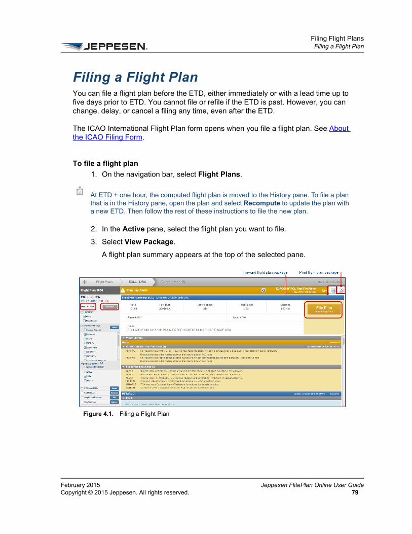
Filing Flight PlansFiling a Flight Plan
FeCo
Filing a Flight PlanYou can file a flight plan before the ETD, either immediately or with a lead time up to five days prior to ETD. You cannot file or refile if the ETD is past. However, you can change, delay, or cancel a filing any time, even after the ETD.
The ICAO International Flight Plan form opens when you file a flight plan. See About the ICAO Filing Form.
To file a flight plan
1. On the navigation bar, select Flight Plans.
2. In the Active pane, select the flight plan you want to file.
3. Select View Package.
A flight plan summary appears at the top of the selected pane.
At ETD + one hour, the computed flight plan is moved to the History pane. To file a plan that is in the History pane, open the plan and select Recompute to update the plan with a new ETD. Then follow the rest of these instructions to file the new plan.
Figure 4.1. Filing a Flight Plan
bruary 2015 Jeppesen FlitePlan Online User Guidepyright © 2015 Jeppesen. All rights reserved. 79
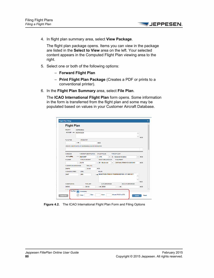
Filing Flight PlansFiling a Flight Plan
Je80
4. In flight plan summary area, select View Package.
The flight plan package opens. Items you can view in the package are listed in the Select to View area on the left. Your selected content appears in the Computed Flight Plan viewing area to the right.
5. Select one or both of the following options:
– Forward Flight Plan
– Print Flight Plan Package (Creates a PDF or prints to a conventional printer).
6. In the Flight Plan Summary area, select File Plan.
The ICAO International Flight Plan form opens. Some information in the form is transferred from the flight plan and some may be populated based on values in your Customer Aircraft Database.
Figure 4.2. The ICAO International Flight Plan Form and Filing Options
ppesen FlitePlan Online User Guide February 2015Copyright © 2015 Jeppesen. All rights reserved.
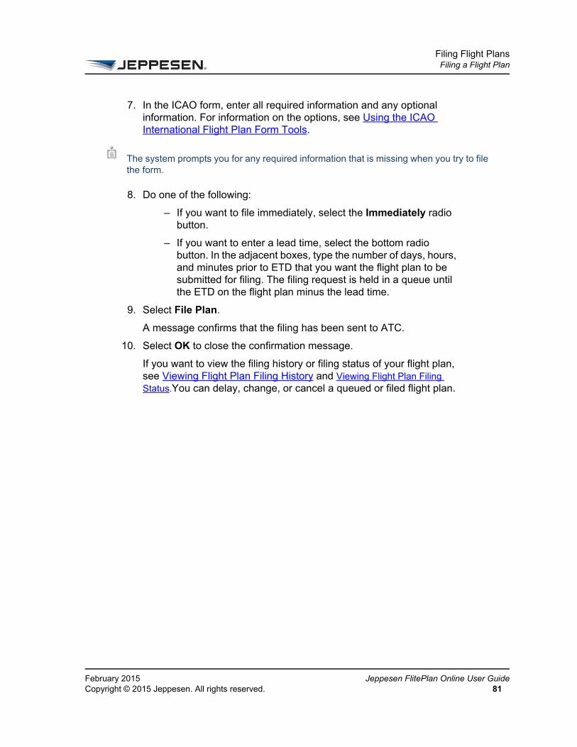
Filing Flight PlansFiling a Flight Plan
FeCo
7. In the ICAO form, enter all required information and any optional information. For information on the options, see Using the ICAO International Flight Plan Form Tools.
8. Do one of the following:
– If you want to file immediately, select the Immediately radio button.
– If you want to enter a lead time, select the bottom radio button. In the adjacent boxes, type the number of days, hours, and minutes prior to ETD that you want the flight plan to be submitted for filing. The filing request is held in a queue until the ETD on the flight plan minus the lead time.
9. Select File Plan.
A message confirms that the filing has been sent to ATC.
10. Select OK to close the confirmation message.
If you want to view the filing history or filing status of your flight plan, see Viewing Flight Plan Filing History and Viewing Flight Plan Filing Status.You can delay, change, or cancel a queued or filed flight plan.
The system prompts you for any required information that is missing when you try to file the form.
bruary 2015 Jeppesen FlitePlan Online User Guidepyright © 2015 Jeppesen. All rights reserved. 81

Filing Flight PlansViewing a Filing Strip
Je82
Viewing a Filing StripThe filing strip is part of the complete flight plan. You can view it in the flight plan in the Flight Plan Package.
To view a filing strip
1. On the navigation bar, select Flight Plans.
2. In the list of flight plans in the Active pane or History pane, select the flight plan whose filing strip you want to view.
A summary of the flight plan appears at the top of the selected pane.
3. In the flight plan summary area, select View Package.
The flight plan package opens. Items you can view in the package are listed in the Select to View area on the left. Your selected content appears in the viewing area to the right.
4. In the Select to View area, make sure that Flight Plan is selected.
5. In the viewing area, select View Full Plan under the Flight Plan Summary.
6. Scroll down in the flight plan to view the filing strip.
Figure 4.3. Filing Strip in a Flight Plan
You can also see the filing strip when viewing ATC message details in the Filing History list. See Viewing Flight Plan Filing History.
ppesen FlitePlan Online User Guide February 2015Copyright © 2015 Jeppesen. All rights reserved.

Filing Flight PlansPrinting a Filing Strip
FeCo
Printing a Filing StripThe filing strip is part of the full flight plan, which is included in the flight plan package and can be printed. See Printing a Flight Plan Package.
bruary 2015 Jeppesen FlitePlan Online User Guidepyright © 2015 Jeppesen. All rights reserved. 83

Filing Flight PlansChanging a Queued or Filed Flight Plan
Je84
Changing a Queued or Filed Flight PlanYou can change only the following elements in a queued or filed flight plan:
• Type of Flight
• Type of Aircraft
• Wake Turbulence Category
• NAVAID Equipment
• Other Information (Remarks)
Other changes require that you cancel the flight plan, modify it, and refile. See Cancelling a Flight Plan Filing.
To change a queued or filed flight plan
1. On the navigation bar, select Flight Plans.
2. In the list of flight plans in the Active pane or History pane, select the flight plan whose filing you want to change.
A summary of the flight plan appears at the top of the selected pane.
3. In the flight plan summary area, select View Package.
The flight plan package opens. Items you can view in the package are listed in the Advanced Flight Options area on the left. Your selected content appears in the viewing area to the right.
4. In the Advanced Flight Options area, make sure that Flight Plan is selected.
5. In the Filing Options area of the Flight Plan Summary, select Change.
The ICAO International Flight Plan form opens, populated with previously entered data. For detailed information on the form options, see Using the ICAO International Flight Plan Form Tools.
6. Make the desired changes. You can modify only the following items:
– Type of Flight
– Type of Aircraft
– Wake Turbulence Category
– NAVAID Equipment
– Other Information (Remarks)
ppesen FlitePlan Online User Guide February 2015Copyright © 2015 Jeppesen. All rights reserved.

Filing Flight PlansChanging a Queued or Filed Flight Plan
FeCo
7. Select File Plan.
A message confirms that the filing has been sent to ATC.
8. Select OK to close the confirmation message.
The status of the plan does not change.
bruary 2015 Jeppesen FlitePlan Online User Guidepyright © 2015 Jeppesen. All rights reserved. 85
Filing Flight PlansCancelling a Flight Plan Filing
Je86
Cancelling a Flight Plan FilingYou can cancel any queued or filed flight plan. When you cancel a filing, the flight plan has an ATC Status of “Cancelled,” but the transaction remains listed in the list of flight plans. You can choose to refile a cancelled flight plan.
To cancel a flight plan filing
1. On the navigation bar, select Flight Plans.
2. In the list of flight plans in the Active pane or History pane, select the flight plan whose filing you want to cancel.
A summary of the flight plan appears at the top of the selected pane.
3. In the flight plan summary area, select View Package.
The flight plan package opens. Items you can view in the package are listed in the Select to View area on the left. Your selected content appears in the viewing area to the right.
4. In the Select to View area, make sure that Flight Plan is selected.
5. In the Flight Plan Summary area in the viewing area, select Cancel.
A message appears, prompting you to confirm that you want to cancel the flight plan filing.
6. Select Yes to close the confirmation message.
A second message confirms that the filing has been cancelled.
7. Select OK to close the confirmation message.
The flight plan remains in the flight plan list, but the status is “Cancelled.”
8. If you want to refile the plan, select File Plan in the Flight Plan Summary area.
ppesen FlitePlan Online User Guide February 2015Copyright © 2015 Jeppesen. All rights reserved.

Filing Flight PlansDelaying a Flight Plan Filing
FeCo
Delaying a Flight Plan FilingYou can delay any queued or filed flight plan. The system sends a “Delay” message immediately to ATC when the ETD changes. Flight plans can be delayed a maximum of 24 hours from the original ETD. The flight plan maintains its position in the ATC queue.
To delay a flight plan filing
1. On the navigation bar, select Flight Plans.
2. In the list of flight plans in the Active pane or History pane, select the flight plan whose filing you want to delay.
A summary of the flight plan appears at the top of the selected pane.
3. In the flight plan summary area, select View Package.
The flight plan package opens. Items you can view in the package are listed in the Select to View area on the left. Your selected content appears in the viewing area to the right.
4. In the Select to View area, make sure that Flight Plan is selected.
5. In the Flight Plan Summary area in the viewing area, select Delay.
The New Estimated Time of Departure dialog box opens.
6. Enter the number of hours and minutes you want to delay the flight plan past ETD in the corresponding boxes.
7. Select Submit.
A dialog box confirms that the delay request has been sent.
8. Select OK in the confirmation dialog box.
The status of the plan does not change.
bruary 2015 Jeppesen FlitePlan Online User Guidepyright © 2015 Jeppesen. All rights reserved. 87

Filing Flight PlansViewing Flight Plan Filing Status
Je88
Viewing Flight Plan Filing Status1. On the navigation bar, select Flight Plans.
2. In the list of flight plans in the Active or History pane, select the flight plan whose status you want to check.
A summary of the flight plan appears at the top of the selected pane.
3. In the flight plan summary area, select View Package.
The flight plan package opens. Items you can view in the package are listed in the Advanced Flight Options area on the left. Your selected content appears in the viewing area to the right.
The Flight Plan Summary in the viewing area displays the filing status in the status bar. Color also indicates status as follows:
• Green – Filed or queued
• Red – Rejected or cancelled
• Gold – Transmission error
4. Flight plan status updates automatically every 60 seconds. To update the list manually, select the Update ATC Filing Status button in the status bar.
A flight plan status can be one of the following:
You can also view filing status by selecting the flight plan in the Active or History pane. Status is indicated in the summary at the top of the pane and in the ATC column, if that is set to show in your list of flight plans.
Table 4-1 Flight Plan Statuses
Status Description
Queued The flight plan is awaiting transmission to ATC. Once the flight plan has been transmitted, the status changes to Filed.
Filed The flight plan has been transmitted to ATC.
Cancelled The flight plan has been queued or submitted and subsequently cancelled in response to a “Cancel” request. Note that you can only refile a plan after the previous filing or currently queued flight plan has been cancelled.
ppesen FlitePlan Online User Guide February 2015Copyright © 2015 Jeppesen. All rights reserved.

Filing Flight PlansViewing Flight Plan Filing Status
FeCo
Amended An “Amended” message has been received. An Amended message contains changes ATC wants made to your original filing. Amended messages are only applicable to “Filing” request messages, not to “Change” or “Delay” requests.
Accepted An “Accepted” message has been received in response to the submitted request message (“Filing,” “Delay,” or “Change.”)
Rejected A “Rejected” message has been received in response to the submitted request message (“Filing,” “Delay,” or “Change.”) The request has been rejected or denied by ATC. The message sometimes, but not always, contains the reason for the rejection.
Transmission Error
Indicates an unsuccessful submission/transmission of a flight plan to ATC.
Table 4-1 Flight Plan Statuses
Status Description
bruary 2015 Jeppesen FlitePlan Online User Guidepyright © 2015 Jeppesen. All rights reserved. 89
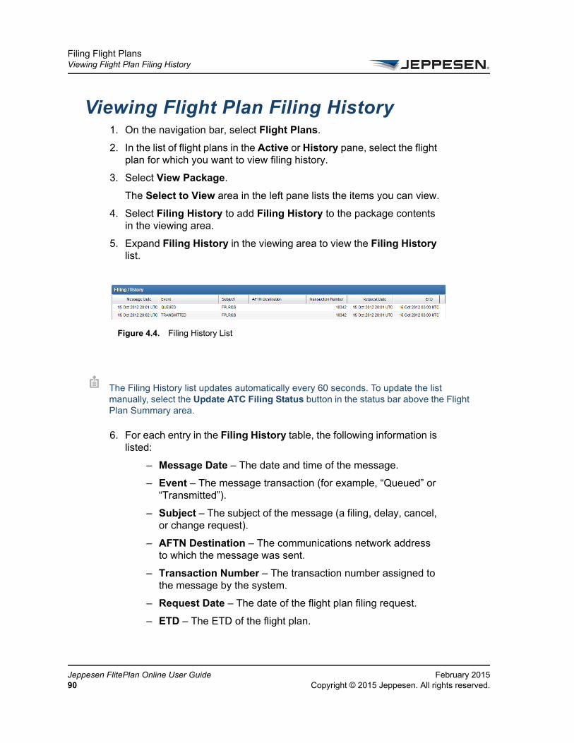
Filing Flight PlansViewing Flight Plan Filing History
Je90
Viewing Flight Plan Filing History1. On the navigation bar, select Flight Plans.
2. In the list of flight plans in the Active or History pane, select the flight plan for which you want to view filing history.
3. Select View Package.
The Select to View area in the left pane lists the items you can view.
4. Select Filing History to add Filing History to the package contents in the viewing area.
5. Expand Filing History in the viewing area to view the Filing History list.
6. For each entry in the Filing History table, the following information is listed:
– Message Date – The date and time of the message.
– Event – The message transaction (for example, “Queued” or “Transmitted”).
– Subject – The subject of the message (a filing, delay, cancel, or change request).
– AFTN Destination – The communications network address to which the message was sent.
– Transaction Number – The transaction number assigned to the message by the system.
– Request Date – The date of the flight plan filing request.
– ETD – The ETD of the flight plan.
Figure 4.4. Filing History List
The Filing History list updates automatically every 60 seconds. To update the list manually, select the Update ATC Filing Status button in the status bar above the Flight Plan Summary area.
ppesen FlitePlan Online User Guide February 2015Copyright © 2015 Jeppesen. All rights reserved.

Filing Flight PlansViewing Flight Plan Filing History
FeCo
7. To see the ATC message contents for an event, select the row in the Filing History table. The message details include the filing strip.
An ATC message event is related to but is different from the flight plan filing status. See Viewing Flight Plan Filing Status for more information.
bruary 2015 Jeppesen FlitePlan Online User Guidepyright © 2015 Jeppesen. All rights reserved. 91
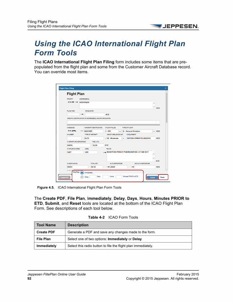
Filing Flight PlansUsing the ICAO International Flight Plan Form Tools
Je92
Using the ICAO International Flight Plan Form ToolsThe ICAO International Flight Plan Filing form includes some items that are pre-populated from the flight plan and some from the Customer Aircraft Database record. You can override most items.
The Create PDF, File Plan, Immediately, Delay, Days, Hours, Minutes PRIOR to ETD, Submit, and Reset tools are located at the bottom of the ICAO Flight Plan Form. See descriptions of each tool below.
Figure 4.5. ICAO International Flight Plan Form Tools
Table 4-2 ICAO Form Tools
Tool Name Description
Create PDF Generate a PDF and save any changes made to the form.
File Plan Select one of two options: Immediately or Delay.
Immediately Select this radio button to file the flight plan immediately.
ppesen FlitePlan Online User Guide February 2015Copyright © 2015 Jeppesen. All rights reserved.

Filing Flight PlansUsing the ICAO International Flight Plan Form Tools
FeCo
About the ICAO Filing Form
The following table contains information on the required and optional elements on the ICAO filing form.
Delay Select this radio button to delay filing the flight plan by specific days, hours, and minutes prior to ETD.
• Days
Type the number of days before the day you wish to file the flight plan.
• Hours
Type the number of hours before you wish to file the flight plan.
• Minutes Prior to ETD
Type the number of Minutes PRIOR to ETD you wish to file your flight plan.
Submit File your flight plan.
Reset Clear your entries in the flight plan filing information.
Table 5 ICAO Filing Form Fields
Form Elements Description
Addressee(s) (Required) This information is transferred from the POD in the flight plan. However, you may edit this field in the filing form. Include a comma or a space between the “A” and the first address. If more than one address is specified, separate each address with a space.
Filing Time Populated automatically when the plan is filed.
Originator Not used
Specific Identification of Addresses or Originator
Not used
Aircraft Identification (Required) The Aircraft Identification field is not prepopulated in the filing form if a value has not been specified in the flight plan request or in the Customer Aircraft Database. In that case, type the information in the Aircraft Identification text box.
Most ARTCCs/ACCs accept only 7 characters.
Flight Rules Defines the flight rule (IFR/VFR/IFR First/VFR First) under which the plan is being filed. This field is always populated from the flight plan.
Table 4-2 ICAO Form Tools
Tool Name Description
bruary 2015 Jeppesen FlitePlan Online User Guidepyright © 2015 Jeppesen. All rights reserved. 93
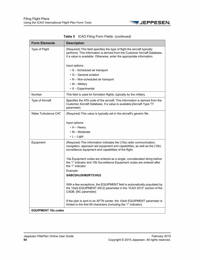
Filing Flight PlansUsing the ICAO International Flight Plan Form Tools
Je94
Type of Flight (Required) This field specifies the type of flight the aircraft typically performs. This information is derived from the Customer Aircraft Database, if a value is available. Otherwise, enter the appropriate information.
Input options:
• S – Scheduled air transport
• G – General aviation
• N – Non-scheduled air transport
• M – Military
• X – Experimental
Number This field is used for formation flights, typically by the military.
Type of Aircraft Specifies the ATA code of the aircraft. This information is derived from the Customer Aircraft Database, if a value is available.[Aircraft Type TY parameter]
Wake Turbulence CAT. (Required) This value is typically set in the aircraft’s generic file.
Input options:
• H – Heavy
• M – Moderate
• L – Light
Equipment (Required) This information indicates the (10a) radio communication, navigation, approach aid equipment and capabilities, as well as the (10b) surveillance equipment and capabilities of the flight.
10a Equipment codes are entered as a single, concatenated string before the “/” indicator and 10b Surveillance Equipment codes are entered after the “/” indicator
Example:
SABCDHJ2KM2RT/CHU2
With a few exceptions, the EQUIPMENT field is automatically populated by the 10a/b EQUIPMENT (NC2) parameter in the “ICAO 2012” section of the CADB. [NC parameter]
If the plan is sent to an AFTN center, the 10a/b EQUIPMENT parameter is limited to the first 69 characters (including the “/” indicator).
EQUIPMENT 10a codes
Table 5 ICAO Filing Form Fields (continued)
Form Elements Description
ppesen FlitePlan Online User Guide February 2015Copyright © 2015 Jeppesen. All rights reserved.
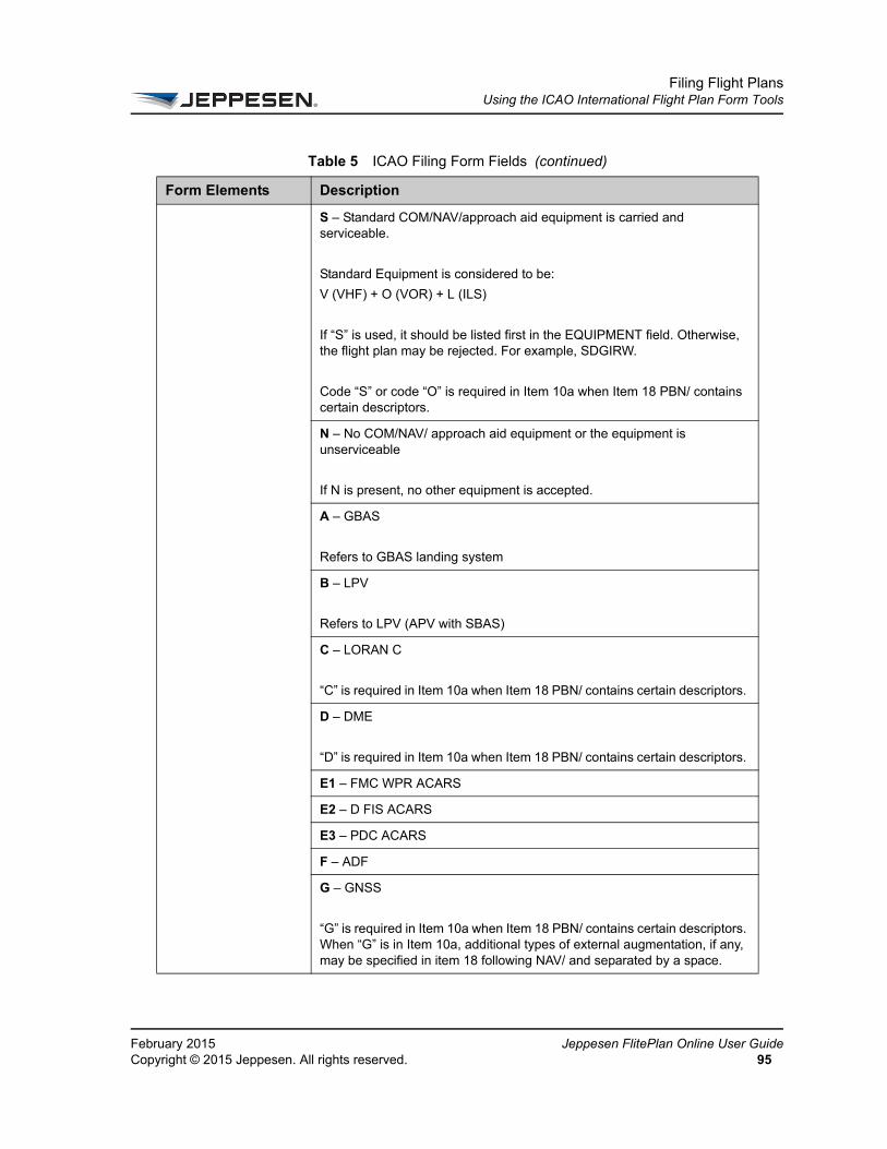
Filing Flight PlansUsing the ICAO International Flight Plan Form Tools
FeCo
S – Standard COM/NAV/approach aid equipment is carried and serviceable.
Standard Equipment is considered to be:
V (VHF) + O (VOR) + L (ILS)
If “S” is used, it should be listed first in the EQUIPMENT field. Otherwise, the flight plan may be rejected. For example, SDGIRW.
Code “S” or code “O” is required in Item 10a when Item 18 PBN/ contains certain descriptors.
N – No COM/NAV/ approach aid equipment or the equipment is unserviceable
If N is present, no other equipment is accepted.
A – GBAS
Refers to GBAS landing system
B – LPV
Refers to LPV (APV with SBAS)
C – LORAN C
“C” is required in Item 10a when Item 18 PBN/ contains certain descriptors.
D – DME
“D” is required in Item 10a when Item 18 PBN/ contains certain descriptors.
E1 – FMC WPR ACARS
E2 – D FIS ACARS
E3 – PDC ACARS
F – ADF
G – GNSS
“G” is required in Item 10a when Item 18 PBN/ contains certain descriptors. When “G” is in Item 10a, additional types of external augmentation, if any, may be specified in item 18 following NAV/ and separated by a space.
Table 5 ICAO Filing Form Fields (continued)
Form Elements Description
bruary 2015 Jeppesen FlitePlan Online User Guidepyright © 2015 Jeppesen. All rights reserved. 95

Filing Flight PlansUsing the ICAO International Flight Plan Form Tools
Je96
H – HF RTF
I – Inertial Navigation
“I” is required in Item 10a when Item 18 PBN/ contains certain descriptors.
J1 – CPDLC ATN VDL Mode 2
J2 – CPDLC FANS 1/A HFDL
J3 – CPDLC FANS 1/A VDL Mode A
J4 – CPDLC FANS 1/A VDL Mode 2
J5 – CPDLC FANS 1/A SATCOM (INM)
J6 – CPDLC FANS 1/A SATCOM (MTS)
J7 – CPDLC FANS 1/A SATCOM (IRID)
K – MLS
L – ILS
L – ILS is considered Standard Equipment (S).
M1 – ATC RTF SATCOM (INMARSAT)
M2 – ATC RTF (MTSAT)
M3 – ATC RTF (Iridium)
O – VOR
O – VOR is considered Standard Equipment (S).
“O” is required in Item 10a when Item 18 PBN/ contains certain descriptors.
R – PBN Approved
Indicates whether or not the aircraft has Performance Based Navigation (PBN) capabilities.
This field is populated from the PBN Certified (I1) parameter in the “ICAO 2012” section of the CADB.
The insertion of R in field 10a requires that the PBN levels must also be specified after the PBN/ indicator in Item 18. Otherwise, the flight plan may be rejected.
See “S – Standard Equipment” above.
Table 5 ICAO Filing Form Fields (continued)
Form Elements Description
ppesen FlitePlan Online User Guide February 2015Copyright © 2015 Jeppesen. All rights reserved.
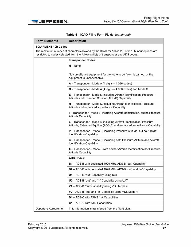
Filing Flight PlansUsing the ICAO International Flight Plan Form Tools
FeCo
EQUIPMENT 10b Codes
The maximum number of characters allowed by the ICAO for 10b is 20. Item 10b input options are restricted to codes selected from the following lists of transponder and ADS codes.
Transponder Codes:
N – None
No surveillance equipment for the route to be flown is carried, or the equipment is unserviceable.
A – Transponder - Mode A (4 digits – 4 096 codes)
C – Transponder - Mode A (4 digits – 4 096 codes) and Mode C
E – Transponder - Mode S, including Aircraft Identification, Pressure-Altitude and Extended Squitter (ADS-B) Capability
H – Transponder - Mode S, including Aircraft Identification, Pressure-Altitude and enhanced surveillance Capability
I – Transponder - Mode S, including Aircraft Identification, but no Pressure-Altitude Capability
L – Transponder - Mode S, including Aircraft Identification, Pressure-Altitude, Extended Squitter (ADS-B) and enhanced surveillance Capability
P – Transponder – Mode S, including Pressure-Altitude, but no Aircraft Identification Capability
S – Transponder – Mode S, including both Pressure-Altitude and Aircraft Identification Capability
X – Transponder – Mode S with neither Aircraft Identification nor Pressure-Altitude Capability
ADS Codes:
B1 – ADS-B with dedicated 1090 MHz ADS-B “out” Capability
B2 – ADB-B with dedicated 1090 MHz ADS-B “out” and “in” Capability
U1 – ADS-B “out” Capability using UAT
U2 – ADS-B “out” and “in” Capability using UAT
V1 – ADS-B “out” Capability using VDL Mode 4
V2 – ADS-B “out” and “in” Capability using VDL Mode 4
D1 – ADS-C with FANS 1/A Capabilities
G1 – ADS-C with ATN Capabilities
Departure Aerodrome This information is transferred from the flight plan.
Table 5 ICAO Filing Form Fields (continued)
Form Elements Description
bruary 2015 Jeppesen FlitePlan Online User Guidepyright © 2015 Jeppesen. All rights reserved. 97

Filing Flight PlansUsing the ICAO International Flight Plan Form Tools
Je98
Time (UTC) (Required) This information is transferred from the flight plan. However, you may change the time if necessary.
Cruising Speed This information is transferred from the flight plan.
Level This information is transferred from the flight plan.
Route This information is transferred from the flight plan.
Destination Aerodrome This information is transferred from the flight plan.
Total EET This information is transferred from the flight plan.
Altn Aerodrome This information is transferred from the flight plan. However, you may edit this field in the filing form.
2nd Alternate Aerodrome
May be populated from the flight plan if your format supports it. You may also provide this information if necessary.
Other Information This command is for anything that might go in Item 18. This information is derived from the flight plan or from the Customer Aircraft Database, if values are available, but can be edited. The following indicators are available. [Multiple parameters, including OR, DL, SC, and RN]
Item 18 Indicators
Leave all indicator fields blank if no Item 18 indicators are used.
Do not use special characters, including an oblique slash (/) in Field 18 text.
Table 5 ICAO Filing Form Fields (continued)
Form Elements Description
ppesen FlitePlan Online User Guide February 2015Copyright © 2015 Jeppesen. All rights reserved.
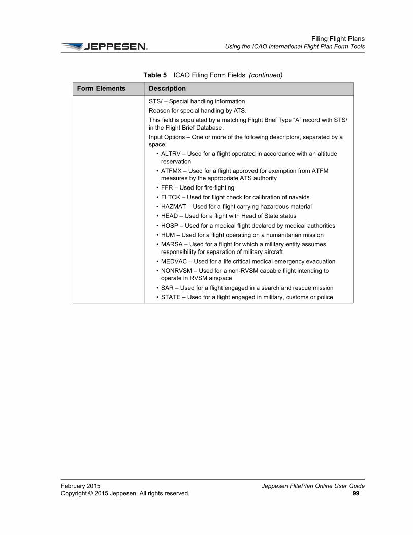
Filing Flight PlansUsing the ICAO International Flight Plan Form Tools
FeCo
STS/ – Special handling information
Reason for special handling by ATS.
This field is populated by a matching Flight Brief Type “A” record with STS/ in the Flight Brief Database.
Input Options – One or more of the following descriptors, separated by a space:
• ALTRV – Used for a flight operated in accordance with an altitude reservation
• ATFMX – Used for a flight approved for exemption from ATFM measures by the appropriate ATS authority
• FFR – Used for fire-fighting
• FLTCK – Used for flight check for calibration of navaids
• HAZMAT – Used for a flight carrying hazardous material
• HEAD – Used for a flight with Head of State status
• HOSP – Used for a medical flight declared by medical authorities
• HUM – Used for a flight operating on a humanitarian mission
• MARSA – Used for a flight for which a military entity assumes responsibility for separation of military aircraft
• MEDVAC – Used for a life critical medical emergency evacuation
• NONRVSM – Used for a non-RVSM capable flight intending to operate in RVSM airspace
• SAR – Used for a flight engaged in a search and rescue mission
• STATE – Used for a flight engaged in military, customs or police
Table 5 ICAO Filing Form Fields (continued)
Form Elements Description
bruary 2015 Jeppesen FlitePlan Online User Guidepyright © 2015 Jeppesen. All rights reserved. 99
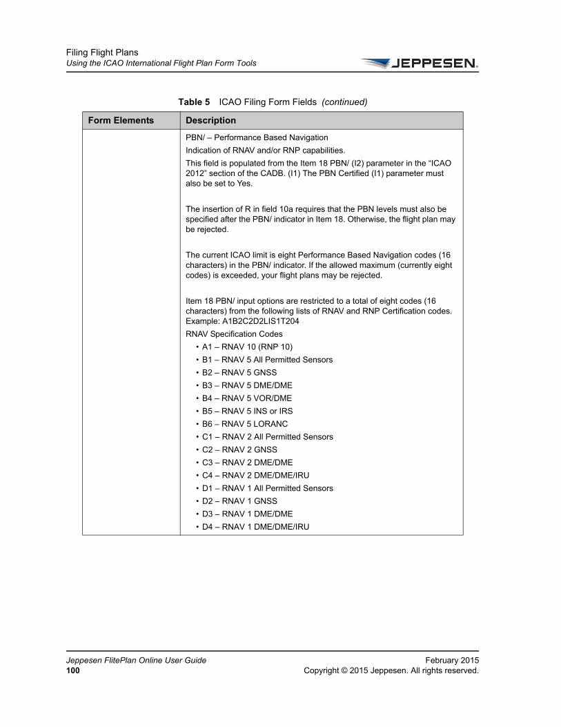
Filing Flight PlansUsing the ICAO International Flight Plan Form Tools
Je10
PBN/ – Performance Based Navigation
Indication of RNAV and/or RNP capabilities.
This field is populated from the Item 18 PBN/ (I2) parameter in the “ICAO 2012” section of the CADB. (I1) The PBN Certified (I1) parameter must also be set to Yes.
The insertion of R in field 10a requires that the PBN levels must also be specified after the PBN/ indicator in Item 18. Otherwise, the flight plan may be rejected.
The current ICAO limit is eight Performance Based Navigation codes (16 characters) in the PBN/ indicator. If the allowed maximum (currently eight codes) is exceeded, your flight plans may be rejected.
Item 18 PBN/ input options are restricted to a total of eight codes (16 characters) from the following lists of RNAV and RNP Certification codes. Example: A1B2C2D2LIS1T204
RNAV Specification Codes
• A1 – RNAV 10 (RNP 10)
• B1 – RNAV 5 All Permitted Sensors
• B2 – RNAV 5 GNSS
• B3 – RNAV 5 DME/DME
• B4 – RNAV 5 VOR/DME
• B5 – RNAV 5 INS or IRS
• B6 – RNAV 5 LORANC
• C1 – RNAV 2 All Permitted Sensors
• C2 – RNAV 2 GNSS
• C3 – RNAV 2 DME/DME
• C4 – RNAV 2 DME/DME/IRU
• D1 – RNAV 1 All Permitted Sensors
• D2 – RNAV 1 GNSS
• D3 – RNAV 1 DME/DME
• D4 – RNAV 1 DME/DME/IRU
Table 5 ICAO Filing Form Fields (continued)
Form Elements Description
ppesen FlitePlan Online User Guide February 20150 Copyright © 2015 Jeppesen. All rights reserved.

Filing Flight PlansUsing the ICAO International Flight Plan Form Tools
FeCo
NAV/ – Navigation equipment
Significant data related to navigation equipment, other than specified in PBN/ as required by the appropriate ATS authority.
This field is automatically populated from the Other Equipment (OE) parameter in the “ATS Plan” section of the CADB.
If a “Z” is in Item 10a, the other equipment or other capabilities must be specified in Item 18, preceded by COM/, NAV/, and/or DAT/, as appropriate (and vice versa).
When “G” is in Item 10a, additional types of external augmentation, if any, may be specified in item 18 following NAV/ and separated by a space.
COM/ – Communication applications or capabilities
Indicates additional communications applications or capabilities for the aircraft that are not covered by the codes for Item 10a.
This field is populated from the Item 18/ COM (I3) parameter in the “ICAO 2012” section of the CADB.
Input value: EUROCONTROL only accepts 50 characters.
If “Z” is in Item 10a, the other equipment or other capabilities must be specified in Item 18, preceded by COM/, NAV/, or DAT/, as appropriate (and vice versa).
If the 8.33 KHz Communication (83) parameter is set to “Permit (P)” or “Exempt (E)” in the “Equipment” section of the CADB, “EXM833” is inserted in Item 18 COM/.
DAT/ – Data applications and capabilities
Indicates additional data applications or capabilities for the aircraft that are not covered by the codes for Item 10a.
This field is populated from the Item 18/ DAT (I4) parameter in the “ICAO 2012” section of the CADB.
Input value: EUROCONTROL only accepts 50 characters
If “Z” is in Item 10a, the other equipment or other capabilities must be specified in Item 18, preceded by COM/, NAV/, and/or DAT/, as appropriate (and vice versa).
Table 5 ICAO Filing Form Fields (continued)
Form Elements Description
bruary 2015 Jeppesen FlitePlan Online User Guidepyright © 2015 Jeppesen. All rights reserved. 101

Filing Flight PlansUsing the ICAO International Flight Plan Form Tools
Je10
SUR/ – Surveillance applications and capabilities
Indicates surveillance applications or capabilities for the aircraft that are not covered by the codes for Item 10b.
This field is populated from the Item 18/ SUR (I5) parameter in the “ICAO 2012” section of the CADB.
Input value: EUROCONTROL only accepts 50 characters.
DEP/ – Name and location of departure airport if ZZZZ is in Item 13 on filing form.
This information is derived from the flight plan. It is only output if the departure airport is ZZZZ.
DEST/ – Name and location of destination airport if ZZZZ is in Item 16.
This information is derived from the flight plan. It is only output if the destination airport is ZZZZ.
DOF/ – Date of flight departure
This information is transferred from the flight plan.
REG/ – Nationality or common mark and registration mark of aircraft
This field is populated by the Registration Number (RN) parameter in the CADB.
EET/ – Significant points or FIR boundary designators and accumulated estimated elapsed times
This information is transferred from the flight plan.
SEL/ – Special Code, for aircraft so equipped
This field is populated by the (SC) SELCAL CODE parameter in the CADB
TYP/ – Type(s) of aircraft if ZZZZ in Item 9
This is not currently supported.
CODE/ – Aircraft address
Specifies the aircraft address for the aircraft, expressed in the form of an alphanumerical code of six hexadecimal characters (as prescribed by the appropriate ATS authority). For example, F00001 is the lowest aircraft address contained in the specific block administered by ICAO.
This field is populated from the Item 18/ CODE (I6) parameter in the “ICAO 2012” section of the CADB.
Input value: Alphanumeric code of six hexadecimal characters.
DLE/ – Enroute delay or holding
Derived from the ETD input by user.
Table 5 ICAO Filing Form Fields (continued)
Form Elements Description
ppesen FlitePlan Online User Guide February 20152 Copyright © 2015 Jeppesen. All rights reserved.

Filing Flight PlansUsing the ICAO International Flight Plan Form Tools
FeCo
OPR/ – ICAO designator or name of the aircraft operating agency
Populated by the Company Name (CN) and OPR Required (OR) parameters in the CADB.
ORGN/ – Originator’s 8 letter AFTN address
This field is populated by a matching Flight Brief Type “A” record with ORG/ in the Flight Brief Database.
Input value: Up to 30 alphanumeric characters
PER/ – Aircraft performance data
Allows you to enter aircraft performance data as prescribed by the appropriate ATS authority. The data is indicated by a single letter as specified in the ICAO document: Procedures for Air Navigation Services — Aircraft Operations (PANS-OPS, Doc 8168), Volume I — Flight Procedures.
This field is populated from the Item 18/ PER (I7) parameter in the “ICAO 2012” section of the CADB.
Input value: One (1) alphanumeric character only. Permissible values are: A, B, C, D, E, or H. May be left blank.
ALTN/ – Destination alternate if ZZZZ in Item 16
This information is derived from the flight plan. It is only output if the destination alternate is ZZZZ.
RALT/ – Enroute alternates
ETOPS alternates for flight.
This information is derived from the flight plan.
Requires RALT Preference to be set for output. Contact Jeppesen Technical Support if needed.
TALT/ – Takeoff alternate
This information is transferred from the flight plan.
RIF/ – Reclear information
Route to reclear airport
This information is transferred from the flight plan.
Only output if customer format supports it.
RMK/ – Other remarks
This is a free-text field. As a general guideline, anything not covered in any of the available Item 18 sub-fields may be put in RMK/.
Table 5 ICAO Filing Form Fields (continued)
Form Elements Description
bruary 2015 Jeppesen FlitePlan Online User Guidepyright © 2015 Jeppesen. All rights reserved. 103
This field is automatically populated from the Flight Brief Text parameter in the Fight Brief Database.
RMK/ output can also be generated from other data sources, such as a customer’s ID Attribute File.
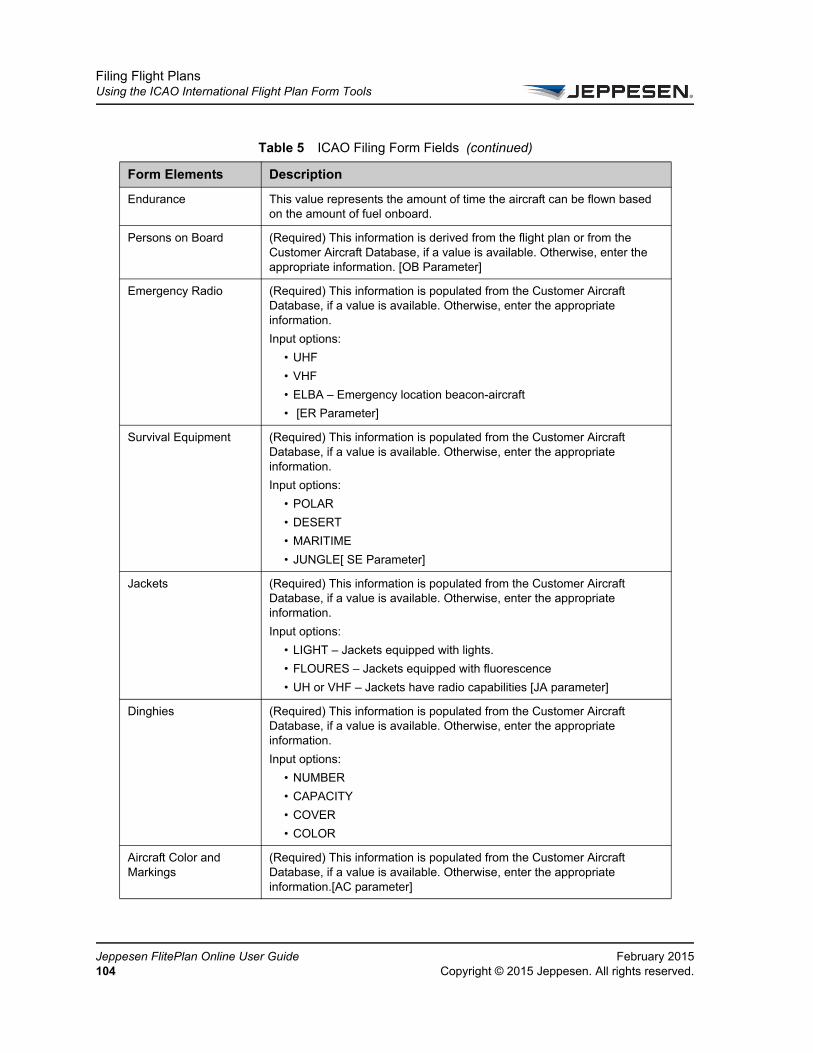
Filing Flight PlansUsing the ICAO International Flight Plan Form Tools
Je10
Endurance This value represents the amount of time the aircraft can be flown based on the amount of fuel onboard.
Persons on Board (Required) This information is derived from the flight plan or from the Customer Aircraft Database, if a value is available. Otherwise, enter the appropriate information. [OB Parameter]
Emergency Radio (Required) This information is populated from the Customer Aircraft Database, if a value is available. Otherwise, enter the appropriate information.
Input options:
• UHF
• VHF
• ELBA – Emergency location beacon-aircraft
• [ER Parameter]
Survival Equipment (Required) This information is populated from the Customer Aircraft Database, if a value is available. Otherwise, enter the appropriate information.
Input options:
• POLAR
• DESERT
• MARITIME
• JUNGLE[ SE Parameter]
Jackets (Required) This information is populated from the Customer Aircraft Database, if a value is available. Otherwise, enter the appropriate information.
Input options:
• LIGHT – Jackets equipped with lights.
• FLOURES – Jackets equipped with fluorescence
• UH or VHF – Jackets have radio capabilities [JA parameter]
Dinghies (Required) This information is populated from the Customer Aircraft Database, if a value is available. Otherwise, enter the appropriate information.
Input options:
• NUMBER
• CAPACITY
• COVER
• COLOR
Aircraft Color and Markings
(Required) This information is populated from the Customer Aircraft Database, if a value is available. Otherwise, enter the appropriate information.[AC parameter]
Table 5 ICAO Filing Form Fields (continued)
Form Elements Description
ppesen FlitePlan Online User Guide February 20154 Copyright © 2015 Jeppesen. All rights reserved.

Filing Flight PlansUsing the ICAO International Flight Plan Form Tools
FeCo
Remarks This text field is available for a text message you wish to include with the filing, such as remarks related to ATC handling. Information may be transferred from the Flight Brief Database.
Pilot-In-Command This information is transferred from the flight plan if a name was entered. Otherwise, enter the appropriate information.
Filed By (Required) Enter the name of the person who is filing the flight plan.
Accepted By Enter the name of the person who accepted the flight plan.
Additional Information Type additional comments in this text box.
Table 5 ICAO Filing Form Fields (continued)
Form Elements Description
bruary 2015 Jeppesen FlitePlan Online User Guidepyright © 2015 Jeppesen. All rights reserved. 105

Filing Flight PlansTest Filing with EUROCONTROL
Je10
Test Filing with EUROCONTROLEUROCONTROL offers a test file validation service that allows you to check in advance that a computed flight plan is accepted for filing when submitted to EUROCONTROL. This service applies only to flight plans that are submitted to EUROCONTROL (those that enter European airspace). Test filing does not guarantee that the flight plan is accepted when it is filed, but provides an indication. This allows you to correct errors that would prevent your flight plan from being accepted, before it is time to file.
To use the EUROCONTROL test file validation service in Jeppesen FlitePlan Online, see the following topics:
• About the EUROCONTROL Test Filing Process
• Computing a Flight Plan with EUROCONTROL Test Filing
• Manually Submitting a Flight Plan for EUROCONTROL Test Filing
About the EUROCONTROL Test Filing ProcessWhen you compute a flight plan, Jeppesen FlitePlan Online recognizes if the flight plan falls under EUROCONTROL restrictions. Only flight plans with an ETD in the next 5 days (120 hours) can be submitted for test filing. All qualifying flight plans are then automatically submitted to the EUROCONTROL test filing service. You do not need to take any action to submit a flight plan for test filing. The results of the test filing appear in the Flight Plan Summary area in the flight plan package and on the Flight Plans navigation tab. Results can include: EUROCONTROL Test File Passed, EUROCONTROL Test File Ineligible, and EUROCONTROL Test File Alerts.
Details for any alerts are found in the Alerts area of the Flight Plan Summary.
Computing a Flight Plan with EUROCONTROL Test FilingAll flight plans that qualify for EUROCONTROL test filing is automatically submitted to the test filing service at the time you compute them. You do not have to take any action to submit your flight plan. However, you can increase the likelihood that your flight plan passes by test filing and by selecting certain options on the flight plan form.
ppesen FlitePlan Online User Guide February 20156 Copyright © 2015 Jeppesen. All rights reserved.
Filing Flight PlansTest Filing with EUROCONTROL
FeCo
To understand how to create a new flight plan, see Create a Flight Plan with New Values. When you enter an origin and destination on the flight plan form that fall within EUROCONTROL restrictions, a new option is added to Routing list. Select Optimized for EU to enable EUROCONTROL Route Availability Document (ERAD) routing, allowing the system to create a route that is both optimized and compliant with EUROCONTROL’s traffic flow restrictions. This minimizes errors that may cause your flight plan to fail the test filing validation. The CRAM check box is selected by default when you select Optimized for EU.
If your flight plan does not have both an origin and destination that fall within EUROCONTROL restrictions, the Optimized for EU routing option is not available. However, your flight plan may still fall within EUROCONTROL restrictions if the route of flight crosses EUROCONTROL airspace, or if either the origin or destination is within Europe. Such a flight plan is submitted to the EUROCONTROL test filing service. To minimize errors that may cause your flight plan to fail the test filing validation, go to the Advanced Flight Options pane and select the ERAD check box under Routing. This also optimizes the route according to EUROCONTROL’s traffic flow restrictions.
Manually Submitting a Flight Plan for EUROCONTROL Test FilingYou can manually test-file in the following cases by selecting the Refresh button on the flight plan package:
• When you want to resubmit closer to filing to “double-check.” For example, you might have computed the flight and test-filed 5 days before ETD, and then you want to revalidate the day of the ETD. This excludes cases in which you have changed something in the flight plan (you would need to recompute and the flight plan would be revalidated automatically).
• When you initially computed the plan more than 5 days (120 hours) prior to ETD, and the flight plan could not be test-filed at the time of computation.You can then manually test-file within 5 days (120 hours) prior to ETD.
• If the flight plan was originally computed when the EUROCONTROL filing service was down, and you want to verify it later.
• If for any other reason, you want to double-check the filing.
bruary 2015 Jeppesen FlitePlan Online User Guidepyright © 2015 Jeppesen. All rights reserved. 107

Filing Flight PlansTest Filing with EUROCONTROL
Je10
ppesen FlitePlan Online User Guide February 20158 Copyright © 2015 Jeppesen. All rights reserved.

CHAPTER 5
Working with Weather
With Jeppesen FlitePlan Online, you can view weather reports for airports associated with a flight plan or for ad hoc airports that are not associated with a flight plan. Weather is presented graphically or textually. It appears in graphical form on the Map tab, and in textual form on the Wx and NOTAMs tabs.
This section describes how weather is presented on each tab, with procedures to guide you through viewing weather for specific airports. It includes the following topics:
• About the Map Tab
• About the Wx Tab
• About the NOTAMs Tab

Working with WeatherAbout the Map Tab
Je11
About the Map Tab The Map tab displays graphical weather information for the airports you select. This weather information appears as layers on a navigation chart. You can show or hide the layers by using the associated check boxes.
You can further define the weather information you want to receive using the Theme and Altitude lists in the map options area. You can also view weather information up to 6 hours in the past or up to 72 hours in the future by adjusting the Time-based View slider under the navigation bar at the right of the window. See About the Jeppesen FlitePlan Online Interface.
The system immediately shows the specified weather information for all selected airports listed in the airports bar above the map options area. Before you can view weather information for specific airports, you must select the airports you want to include. To learn how to select airports associated with a flight plan, see Viewing Fixed Airports. To learn how to select ad hoc airports (not associated with a flight plan), see Searching for Ad-Hoc Airports and Jeppesen Navigational Aids.
The Legend tab, located at the bottom of the Map tab, shows how each graphical weather option is depicted on the navigation chart. Select Legend to open the tab. Only the weather options that you select in the map options area are shown.
Figure 5.1. Legend Tab
ppesen FlitePlan Online User Guide February 20150 Copyright © 2015 Jeppesen. All rights reserved.

Working with WeatherAbout the Map Tab
FeCo
The map options area is explained below, including graphical representations where applicable.
Table 5-1 Map Tab Options
Option Description
Theme dropdown menu
Select an option from the Theme menu options to indicate the type of chart you want to view on the Map tab. The options are:
Basic – displays a shaded outline of your chosen geographic location, with overlaid weather information
IFR Enroute (High) – displays high-level IFR enroute tracks
IFR Enroute (Low) – displays low level IFR enroute tracks
VFR – displays the terrain of your chosen geographic location
Chart Altitude dropdown menu
Use the Chart Altitude list to select the altitude for which you want to view weather information. The altitude affects icing, turbulence, and winds aloft.
AIRMETs check box
View areas where Airman’s Meteorological advisories have been issued
SIGMETs check box
View areas where Significant Meteorological (SIGMET) advisories have been issued. SIGMETs are issued for hazardous weather that is considered of extreme importance to all aircraft, and warn of the following weather hazards: severe icing, severe and extreme turbulence, dust storms, sandstorms, or volcanic ash lowering visibility to less than three miles.
METARs check box
View an Aviation Routine Weather Report for the selected area.
Winds Aloft check box
Display wind flags, which give an estimate of wind direction and wind speed for selected levels of altitude.
bruary 2015 Jeppesen FlitePlan Online User Guidepyright © 2015 Jeppesen. All rights reserved. 111

Working with WeatherAbout the Map Tab
Je11
Fronts check box
Display significant cold, warm, stationary, and occluded fronts
Lightning check box
Display areas where lightning has been observed or has high potential for occurring.
Radar Echo Tops check box
Display the maximum height of precipitation echoes. Echo tops information identifies areas of strong thunderstorm updrafts or downbursts.
NEXRAD check box
Display radar detected weather activity for your selected geographic area.
Icing check box Display areas with high potential for icing.
Turbulence check box
Display high turbulence or low-level wind shear activity and potential for activity for your selected geographic area.
Precip Accumulation check box
Display significant areas of precipitation accumulation for your selected geographic area.
Table 5-1 Map Tab Options
Option Description
ppesen FlitePlan Online User Guide February 20152 Copyright © 2015 Jeppesen. All rights reserved.

Working with WeatherAbout the Map Tab
FeCo
Selecting Graphical Weather on the Map Tab1. Select the airports for which you want to view weather information.
You can select airports by creating a new flight plan, selecting a flight plan, or selecting ad hoc airports.
For more information on how to select airports, see Viewing Fixed Airports and Searching for Ad-Hoc Airports and Jeppesen Navigational Aids.
2. Select the Map tab.
3. From the Theme list, select the type of chart you want to view.
4. From the Altitude list, select the altitude for which you want to view graphical weather.
5. If you want to view past graphical weather or a future forecast, select the time you want to view using the Time-based View slider.
6. Select the check boxes for any weather options you want to view. Clear the check boxes for any weather options you do not want to view.
The weather information you selected appears below on the chart. On the Legend tab, a key appears to show how each weather option is depicted.
Airways check box
Display airways. You cannot view airways with the Basic theme, and airways are always displayed when you select the VFR theme. Airways are only visible at high magnification.
TFRs Display temporary flight restrictions. TFRs appear in red or gray on the map, depending on whether they are active or pending.
ETOPS Display the range rings, ETOPS alternates, equal time points, and the ETOPS entry and exit points.
Table 5-1 Map Tab Options
Option Description
bruary 2015 Jeppesen FlitePlan Online User Guidepyright © 2015 Jeppesen. All rights reserved. 113
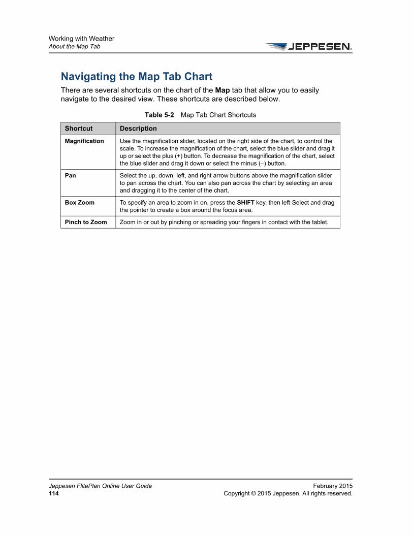
Working with WeatherAbout the Map Tab
Je11
Navigating the Map Tab ChartThere are several shortcuts on the chart of the Map tab that allow you to easily navigate to the desired view. These shortcuts are described below.
Table 5-2 Map Tab Chart Shortcuts
Shortcut Description
Magnification Use the magnification slider, located on the right side of the chart, to control the scale. To increase the magnification of the chart, select the blue slider and drag it up or select the plus (+) button. To decrease the magnification of the chart, select the blue slider and drag it down or select the minus (–) button.
Pan Select the up, down, left, and right arrow buttons above the magnification slider to pan across the chart. You can also pan across the chart by selecting an area and dragging it to the center of the chart.
Box Zoom To specify an area to zoom in on, press the SHIFT key, then left-Select and drag the pointer to create a box around the focus area.
Pinch to Zoom Zoom in or out by pinching or spreading your fingers in contact with the tablet.
ppesen FlitePlan Online User Guide February 20154 Copyright © 2015 Jeppesen. All rights reserved.
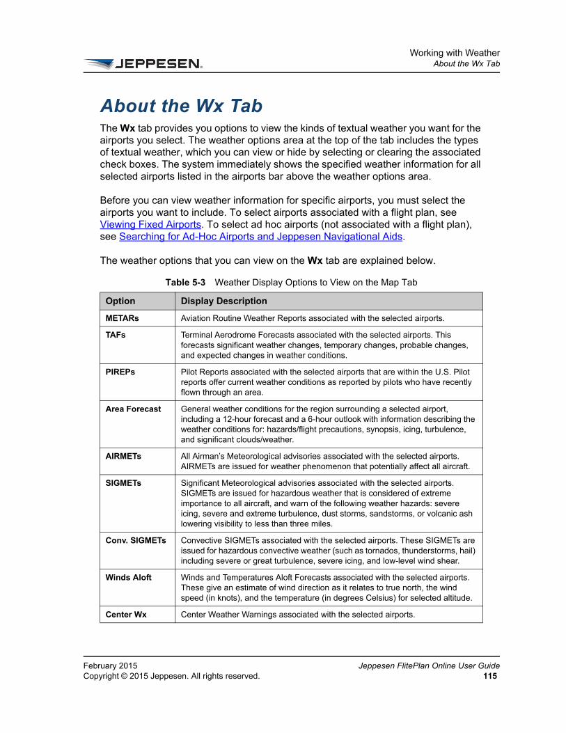
Working with WeatherAbout the Wx Tab
FeCo
About the Wx TabThe Wx tab provides you options to view the kinds of textual weather you want for the airports you select. The weather options area at the top of the tab includes the types of textual weather, which you can view or hide by selecting or clearing the associated check boxes. The system immediately shows the specified weather information for all selected airports listed in the airports bar above the weather options area.
Before you can view weather information for specific airports, you must select the airports you want to include. To select airports associated with a flight plan, see Viewing Fixed Airports. To select ad hoc airports (not associated with a flight plan), see Searching for Ad-Hoc Airports and Jeppesen Navigational Aids.
The weather options that you can view on the Wx tab are explained below.
Table 5-3 Weather Display Options to View on the Map Tab
Option Display Description
METARs Aviation Routine Weather Reports associated with the selected airports.
TAFs Terminal Aerodrome Forecasts associated with the selected airports. This forecasts significant weather changes, temporary changes, probable changes, and expected changes in weather conditions.
PIREPs Pilot Reports associated with the selected airports that are within the U.S. Pilot reports offer current weather conditions as reported by pilots who have recently flown through an area.
Area Forecast General weather conditions for the region surrounding a selected airport, including a 12-hour forecast and a 6-hour outlook with information describing the weather conditions for: hazards/flight precautions, synopsis, icing, turbulence, and significant clouds/weather.
AIRMETs All Airman’s Meteorological advisories associated with the selected airports. AIRMETs are issued for weather phenomenon that potentially affect all aircraft.
SIGMETs Significant Meteorological advisories associated with the selected airports. SIGMETs are issued for hazardous weather that is considered of extreme importance to all aircraft, and warn of the following weather hazards: severe icing, severe and extreme turbulence, dust storms, sandstorms, or volcanic ash lowering visibility to less than three miles.
Conv. SIGMETs Convective SIGMETs associated with the selected airports. These SIGMETs are issued for hazardous convective weather (such as tornados, thunderstorms, hail) including severe or great turbulence, severe icing, and low-level wind shear.
Winds Aloft Winds and Temperatures Aloft Forecasts associated with the selected airports. These give an estimate of wind direction as it relates to true north, the wind speed (in knots), and the temperature (in degrees Celsius) for selected altitude.
Center Wx Center Weather Warnings associated with the selected airports.
bruary 2015 Jeppesen FlitePlan Online User Guidepyright © 2015 Jeppesen. All rights reserved. 115

Working with WeatherAbout the Wx Tab
Je11
Selecting Text Weather on the Wx Tab1. Select the airports for which you want to view weather information.
You can select airports when creating a new flight plan, selecting a flight plan, or selecting ad hoc airports.
For more information on how to select airports, see Viewing Fixed Airports and Searching for Ad-Hoc Airports and Jeppesen Navigational Aids.
2. Select the Wx tab.
3. Select the check boxes for any weather options you want to view. Clear the check boxes for any weather options you do not want to view.
The weather information you selected appears below on the tab.
Severe Wx Severe Weather Warnings associated with the selected airports.
Recreation Forecast
Recreation forecast information associated with the selected airports. This information may not be available for all locations, and the contents of the report varies. Information that may be displayed includes weather forecasts, ski reports, and highway conditions.
City Forecast Current zone forecasts associated with the selected airports.
Hurricane Bulletin
Hurricane forecast information associated with the selected airports.
Volcanic Ash View Volcanic Ash Activity alerts associated with the selected airports.
Table 5-3 Weather Display Options to View on the Map Tab
Option Display Description
ppesen FlitePlan Online User Guide February 20156 Copyright © 2015 Jeppesen. All rights reserved.
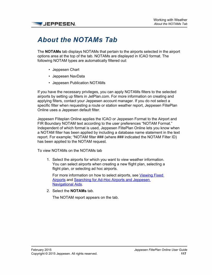
Working with WeatherAbout the NOTAMs Tab
FeCo
About the NOTAMs Tab
The NOTAMs tab displays NOTAMs that pertain to the airports selected in the airport options area at the top of the tab. NOTAMs are displayed in ICAO format. The following NOTAM types are automatically filtered out:
• Jeppesen Chart
• Jeppesen NavData
• Jeppesen Publication NOTAMs
If you have the necessary privileges, you can apply NOTAMs filters to the selected airports by setting up filters in JetPlan.com. For more information on creating and applying filters, contact your Jeppesen account manager. If you do not select a specific filter when requesting a route or station weather report, Jeppesen FlitePlan Online uses a Jeppesen default filter.
Jeppesen Fliteplan Online applies the ICAO or Jeppesen Format to the Airport and FIR Boundary NOTAM text according to the user preferences “NOTAM Format.” Independent of which format is used, Jeppesen FlitePlan Online lets you know when a NOTAM filter has been applied by including a database name statement in the text report. For example; “NOTAM filter ### (where ### indicated the NOTAM Filter ID) has been applied to the NOTAM request.
To view NOTAMs on the NOTAMs tab
1. Select the airports for which you want to view weather information. You can select airports when creating a new flight plan, selecting a flight plan, or selecting ad hoc airports.
For more information on how to select airports, see Viewing Fixed Airports and Searching for Ad-Hoc Airports and Jeppesen Navigational Aids.
2. Select the NOTAMs tab.
The NOTAM report appears on the tab.
bruary 2015 Jeppesen FlitePlan Online User Guidepyright © 2015 Jeppesen. All rights reserved. 117

Working with WeatherAbout the NOTAMs Tab
Je11
ppesen FlitePlan Online User Guide February 20158 Copyright © 2015 Jeppesen. All rights reserved.

CHAPTER 6
Working With RAIM Prediction Reports
This section provides information on generating Receiver Autonomous Integrity Monitoring (RAIM) prediction reports for flight plans and airports. The topics in this section include:
• About RAIM Prediction Reports
• Generating a RAIM Prediction Report for a Flight Plan Package
• Generating RAIM Prediction Reports for Airports
• Sending a RAIM Prediction Report
• About RAIM Prediction Report Options

Working With RAIM Prediction ReportsAbout RAIM Prediction Reports
Je12
About RAIM Prediction ReportsJeppesen FlitePlan Online supports Receiver Autonomous Integrity Monitoring (RAIM) prediction reports. The Receiver autonomous integrity monitoring (RAIM) technology assesses the integrity of global positioning system (GPS) signals in a GPS receiver system. It is of special importance in safety-critical GPS applications, such as in aviation navigation. Jeppesen FlitePlan Online uses algorithms to generate a RAIM prediction for the entire route, including the departure and arrival airports.
You can choose from two kinds of RAIM reports in FPO:
• Settings > Airport RAIM Prediction for a single airport that you select.
• Flight Plan button > View Package > RAIM Report > Generate for all airports in the flight plan package, as well as enroute waypoints in the Flight Plan (if selected).
Requirements for RAIM Prediction Report Requests
The following rules apply for making RAIM report requests:
• You must have Required Navigation Performance (RNP) and/or RAIM permissions set in your ID attribute file. Contact your Jeppesen account manager to ensure that you have the required permissions.
• You can generate RAIM prediction reports for computed flight plans and for individual airports.
• You must first select an aircraft when generating a report for an airport.
• You cannot generate RAIM prediction reports if the Customer Aircraft database indicates that your aircraft is not GPS-equipped.
• RAIM prediction reports use defined values for RNP departure, enroute, and arrival procedures; GPS equipment; and RAIM mask angles.
For more information on using RAIM reports, contact your Jeppesen account manager.
ppesen FlitePlan Online User Guide February 20150 Copyright © 2015 Jeppesen. All rights reserved.
Working With RAIM Prediction ReportsAbout RAIM Prediction Reports
FeCo
• Default values for these items are derived from values (if set) in your Customer Aircraft and Airport databases. If no values are set in the customer databases, system defaults are used. In either case, if you have the necessary RNP and RAIM permissions, you can override the default values when you create the report request. For more information, contact your Jeppesen account manager.
bruary 2015 Jeppesen FlitePlan Online User Guidepyright © 2015 Jeppesen. All rights reserved. 121
Working With RAIM Prediction ReportsGenerating a RAIM Prediction Report for a Flight Plan Package
Je12
Generating a RAIM Prediction Report for a Flight Plan PackageYou can generate a RAIM prediction report for a flight plan package. RAIM prediction reports use defined values for required navigation performance (RNP) for departure, enroute, and arrival procedures; GPS equipment; and RAIM mask angles. Default values for these items are derived from values (if set) in your Customer Aircraft and Airport databases. If no values are set in the customer databases, FPO uses system defaults.
To generate a RAIM prediction report for a flight plan package
1. In the navigation bar, select Flight Plans.
2. In the list of flight plans in the Active pane or History pane, select the flight plan.
A summary of the flight plan appears at the top of the selected pane.
3. In the flight plan summary area, select View Package.
The flight plan package opens. Items you can view in the package are listed in the Select to View area on the left. Your selected content displays in the viewing area to the right.
4. In the Select to View area, select Generate to the right of RAIM Report.
The RAIM Prediction for Flight <Origin to Destination> dialog box opens. For information on the options in this window, see About RAIM Prediction Reports.
5. In the Departure RNP list, accept the default value or select a new value for the departure procedure RNP level.
6. In the Enroute RNP list, accept the default value or select a new value for the enroute procedure RNP level.
7. In the Arrival RNP list, accept the default value or select a new value for the arrival procedure RNP level.
8. In the Airport Mask Angle list, accept the default value or select the airport mask angle for the terrain around the airport.
The customer databases are maintained in JetPlan.com. For more information, contact your Jeppesen account manager.
ppesen FlitePlan Online User Guide February 20152 Copyright © 2015 Jeppesen. All rights reserved.
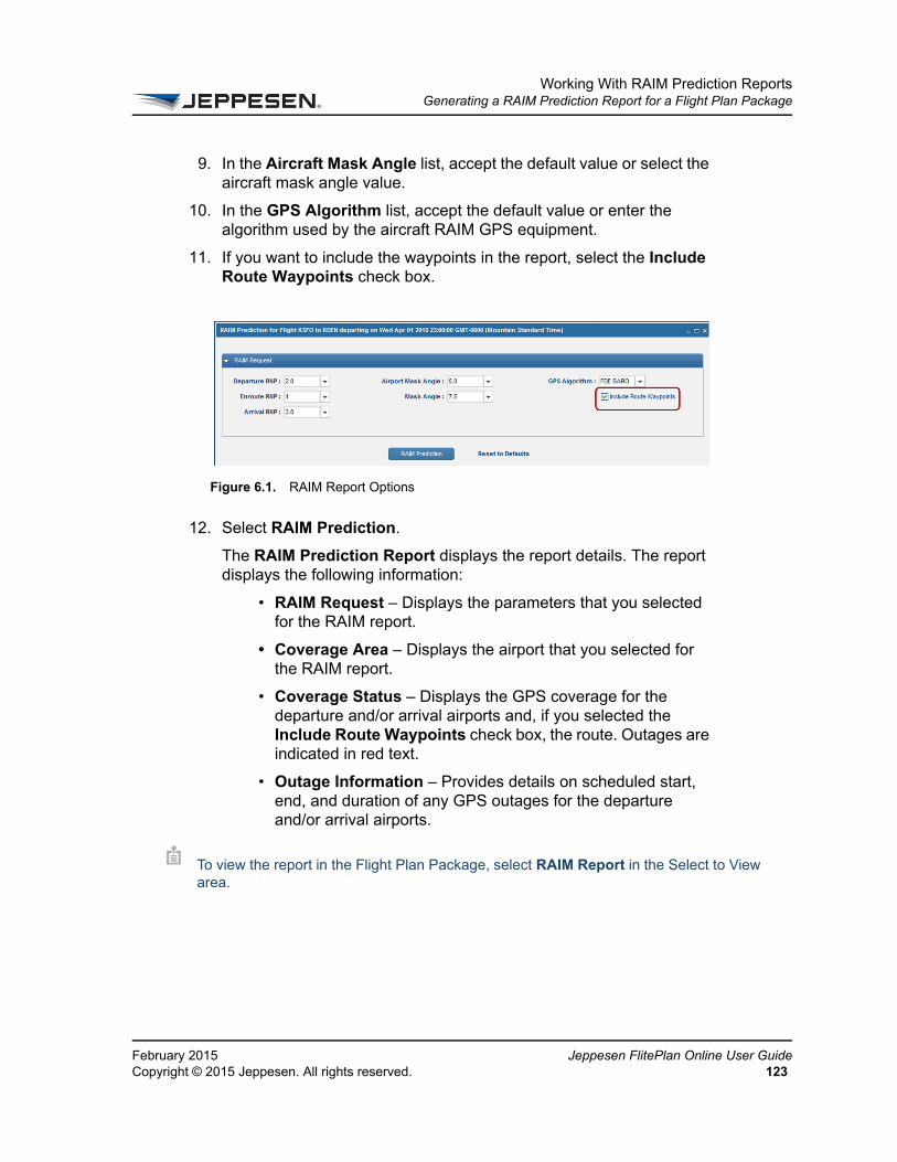
Working With RAIM Prediction ReportsGenerating a RAIM Prediction Report for a Flight Plan Package
FeCo
9. In the Aircraft Mask Angle list, accept the default value or select the aircraft mask angle value.
10. In the GPS Algorithm list, accept the default value or enter the algorithm used by the aircraft RAIM GPS equipment.
11. If you want to include the waypoints in the report, select the Include Route Waypoints check box.
12. Select RAIM Prediction.
The RAIM Prediction Report displays the report details. The report displays the following information:
• RAIM Request – Displays the parameters that you selected for the RAIM report.
• Coverage Area – Displays the airport that you selected for the RAIM report.
• Coverage Status – Displays the GPS coverage for the departure and/or arrival airports and, if you selected the Include Route Waypoints check box, the route. Outages are indicated in red text.
• Outage Information – Provides details on scheduled start, end, and duration of any GPS outages for the departure and/or arrival airports.
Figure 6.1. RAIM Report Options
To view the report in the Flight Plan Package, select RAIM Report in the Select to View area.
bruary 2015 Jeppesen FlitePlan Online User Guidepyright © 2015 Jeppesen. All rights reserved. 123
Working With RAIM Prediction ReportsGenerating RAIM Prediction Reports for Airports
Je12
Generating RAIM Prediction Reports for Airports
You can generate a RAIM report that covers a 24-hour period for an airport when you select a GPS-equipped aircraft. RAIM prediction reports use defined values for Terminal RNP levels, GPS equipment, and RAIM mask angles. Default values for these items are derived from values (if set) in your Customer Aircraft and Airport databases. If no values are set in the customer databases, system defaults are used. For detailed information, see About RAIM Prediction Report Options.
To generate a RAIM Prediction Report for an Airport
1. On the toolbar in the main Jeppesen FlitePlan Online window, select the Settings button.
2. From the menu, select Airport RAIM Prediction to open the Airport RAIM Prediction window.
3. In the Airport box, enter at least three characters of an ICAO code to see a list of airports in your Customer Airport database and then select the airport.
4. In the Airport Mask Angle list, accept the default value or select the airport mask angle for the terrain around the airport.
5. In the Aircraft list, select a GPS-equipped aircraft from your Customer Aircraft database.
6. In the Aircraft Mask Angle list, accept the default value or select a new aircraft mask angle value.
7. In the GPS Algorithm list, accept the default value or select the algorithm used by the aircraft RAIM GPS equipment.
8. In the Terminal RNP list, accept the default value or select the RNP level for the airport.
Aircraft selection is required. If the aircraft record in the Customer Aircraft database does not indicate that the aircraft is GPS-equipped, a message warns you that the report cannot be run.
ppesen FlitePlan Online User Guide February 20154 Copyright © 2015 Jeppesen. All rights reserved.

Working With RAIM Prediction ReportsGenerating RAIM Prediction Reports for Airports
FeCo
9. Select RAIM Prediction.
The RAIM Prediction Report pane displays the report details. The report displays the following information:
– Coverage Area and Coverage Status – Displays the GPS coverage for the airport. Outages are indicated in red text.
– Outage Information – Provides details on scheduled start, end, and duration of any GPS outages for the airport.
bruary 2015 Jeppesen FlitePlan Online User Guidepyright © 2015 Jeppesen. All rights reserved. 125

Working With RAIM Prediction ReportsSending a RAIM Prediction Report
Je12
Sending a RAIM Prediction ReportYou can send the RAIM prediction report as part of the flight plan package. For instructions, see Sending a Flight Plan Package via Email.
ppesen FlitePlan Online User Guide February 20156 Copyright © 2015 Jeppesen. All rights reserved.
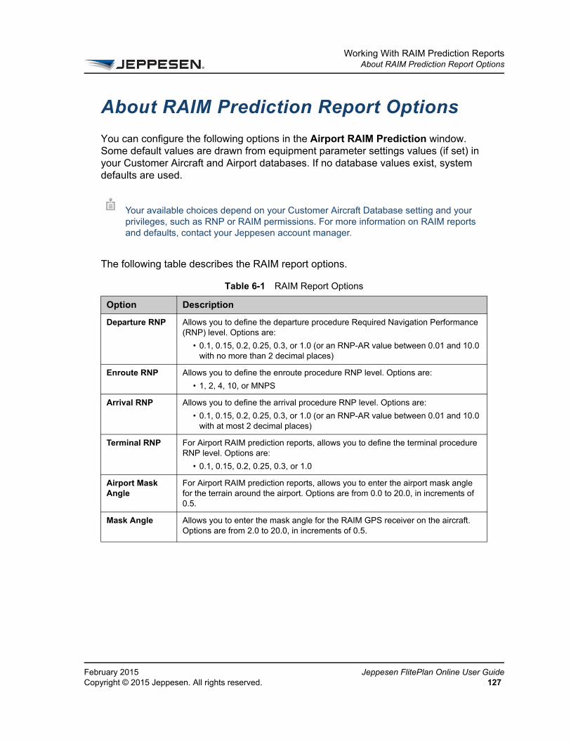
Working With RAIM Prediction ReportsAbout RAIM Prediction Report Options
FeCo
About RAIM Prediction Report Options
You can configure the following options in the Airport RAIM Prediction window. Some default values are drawn from equipment parameter settings values (if set) in your Customer Aircraft and Airport databases. If no database values exist, system defaults are used.
The following table describes the RAIM report options.
Your available choices depend on your Customer Aircraft Database setting and your privileges, such as RNP or RAIM permissions. For more information on RAIM reports and defaults, contact your Jeppesen account manager.
Table 6-1 RAIM Report Options
Option Description
Departure RNP Allows you to define the departure procedure Required Navigation Performance (RNP) level. Options are:
• 0.1, 0.15, 0.2, 0.25, 0.3, or 1.0 (or an RNP-AR value between 0.01 and 10.0 with no more than 2 decimal places)
Enroute RNP Allows you to define the enroute procedure RNP level. Options are:
• 1, 2, 4, 10, or MNPS
Arrival RNP Allows you to define the arrival procedure RNP level. Options are:
• 0.1, 0.15, 0.2, 0.25, 0.3, or 1.0 (or an RNP-AR value between 0.01 and 10.0 with at most 2 decimal places)
Terminal RNP For Airport RAIM prediction reports, allows you to define the terminal procedure RNP level. Options are:
• 0.1, 0.15, 0.2, 0.25, 0.3, or 1.0
Airport Mask Angle
For Airport RAIM prediction reports, allows you to enter the airport mask angle for the terrain around the airport. Options are from 0.0 to 20.0, in increments of 0.5.
Mask Angle Allows you to enter the mask angle for the RAIM GPS receiver on the aircraft. Options are from 2.0 to 20.0, in increments of 0.5.
bruary 2015 Jeppesen FlitePlan Online User Guidepyright © 2015 Jeppesen. All rights reserved. 127

Working With RAIM Prediction ReportsAbout RAIM Prediction Report Options
Je12
GPS Algorithm Allows you to indicate the algorithm used by RAIM GPS Equipment. The default value is FDE BARO if no value has been set for RAIM GPS Algorithm in the Customer Aircraft database record. Otherwise, the value from the database record is used. You can override the default setting. Options are:
• FD – Fault Detection
• FDE – Fault Detection Exclusion
• FD BARO – Fault Detection with Barometric Aiding
• FDE BARO – Fault Detection Exclusion with Barometric Aiding
Include Route Waypoints
Allows you to include waypoints in the RAIM report.
Table 6-1 RAIM Report Options
Option Description
ppesen FlitePlan Online User Guide February 20158 Copyright © 2015 Jeppesen. All rights reserved.
CHAPTER 7
Working With Messaging
This section describes how to use Jeppesen FlitePlan Online to send messages and transactions (such as flight plans) and view ARINC Direct flight plan uplink acknowledgments. The topics in this section are:
• About Messaging
• Sending Emails, Faxes, and Using a Datalink Network
• Sending a Flight Plan to an Aircraft
• Sending a Flight Plan to an Aircraft
• Sending a Flight Plan to an Aircraft
• Sending a Flight Plan Package via Email
• Sending Attachments
• Sending Attachments
• Viewing Message History
• Working with the Address Book
Working With MessagingAbout Messaging
Je13
About MessagingFlitePlan Online allows you to send flight plans, text messages, and attachments, and view and maintain a history of sent messages. You can also maintain an Address Book, which is used to add recipient information to your messages.
You can send the following items:
• Flight plans
• Filing history
• Route and weather map captures
• Weather reports
• NOTAM/TFR reports
• RAIM prediction reports
• Weight and balance reports
• Text messages
You can use the following communication methods:
• Email – Supports text messages and attachments
• Fax – Supports text messages
• ARINC – Supports text messages
• AFTN – Supports text messages
• SITA – Supports text messages
You can also text upload flight plans to aircraft via the Aircraft Communications Addressing and Reporting System (ACARS). The following communications interfaces are supported:
• ACARS (via Universal)
• AFIS (ACARS/AFIS via Honeywell GDC)
• ARINC Direct Uplink (ACARS via ARINC Direct)
To uplink documents to an aircraft, the aircraft’s FMS type must be stored in your Customer Aircraft Database. You can override the default FMS type on the flight plan. Also, you need certain privileges to use the ACARS uplink. For more information, contact your Jeppesen account manager.
ppesen FlitePlan Online User Guide February 20150 Copyright © 2015 Jeppesen. All rights reserved.
Working With MessagingSending Emails, Faxes, and Using a Datalink Network
FeCo
Sending Emails, Faxes, and Using a Datalink Network
You can use Messaging to send emails (with attachments if desired) as well as text messages via fax and datalink (SITA, AFTN, and ARINC). Note that only emails support attachments.
You can choose to send the same message to other types of addresses at the same time. For instance, you can select or enter an email address, a fax address, or a datalink address for one or multiple recipients in the To box of the message.
To send an email or a fax:
1. On the toolbar, select the Messaging icon.
2. From the menu, select Send Message.
The Messaging navigation tab opens.
3. In the To box on the New Message tab, begin typing the name of the single recipient or group.
The system automatically displays a list of matching contacts from your Address Book. If the Address Book contains more than one address, fax number, or datalink address for the recipient, all addresses are listed.
4. From the list of contacts, select the recipient(s) or group(s). If a contact has multiple addresses, select the email address, fax number, or datalink network address in the list.
For information on uplinking a flight plan to an aircraft, see Sending a Flight Plan to an Aircraft.
If you do not know the recipient’s name or if the recipient has not yet been added to the Address Book, select Manage Contacts to open the Address Book navigation tab, where you can look up or add the contact. Select Done to return to the Messaging navigation tab.
bruary 2015 Jeppesen FlitePlan Online User Guidepyright © 2015 Jeppesen. All rights reserved. 131

Working With MessagingSending Emails, Faxes, and Using a Datalink Network
Jeppes132
5. You may also add email addresses, fax numbers, and datalink addresses that are not in the Address Book. In the To box, add the email address or fax number and then select ENTER.
Use the following format for fax numbers: 10 or more numbers up to 16 characters with no spaces. Parentheses and hyphens are allowed as entries.
Use the following format for datalink addresses:
• ARINC address – Seven alphanumeric characters only.
• SITA address – Seven alphanumeric characters only.
• AFTN address – Eight letters only.
You may need to select a network for a datalink address.
6. Select one of the following from the Priority list (applies only to datalink addresses):
• Low – Deferred until after other higher priority messages are delivered.
• Normal – Delivery is guaranteed within three hours.
• Urgent – Delivery is guaranteed within one hour.
These priority settings map to the network priority codes as follows:
7. If you decide to remove an address or fax number, select the remove icon (–) next to the address or fax number.
8. In the Subject box, type the subject of your message.
9. In the Message box, type your message.
You may enter a total of three individual fax numbers or six group fax numbers. You may enter a total of six individual and ten group email addresses. You may enter a total of three individual network addresses and six group addresses.
If you enter an address for either the ARINC or the SITA network, the Select the Network Type dialog box opens. Select the network and then select OK.
Code Type ARINC SITA AFTN
Urgent QU QU FF
Normal QN QN GG
Low (Deferred) QD QD KK
en FlitePlan Online User Guide February 2015Copyright © 2015 Jeppesen. All rights reserved.
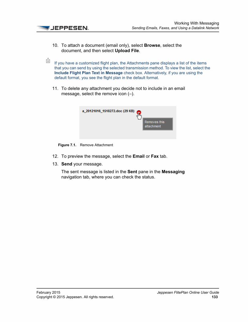
Working With MessagingSending Emails, Faxes, and Using a Datalink Network
FeCo
10. To attach a document (email only), select Browse, select the document, and then select Upload File.
11. To delete any attachment you decide not to include in an email message, select the remove icon (–).
12. To preview the message, select the Email or Fax tab.
13. Send your message.
The sent message is listed in the Sent pane in the Messaging navigation tab, where you can check the status.
If you have a customized flight plan, the Attachments pane displays a list of the items that you can send by using the selected transmission method. To view the list, select the Include Flight Plan Text in Message check box. Alternatively, if you are using the default format, you see the flight plan in the default format.
Figure 7.1. Remove Attachment
bruary 2015 Jeppesen FlitePlan Online User Guidepyright © 2015 Jeppesen. All rights reserved. 133

Working With MessagingSending a Flight Plan to an Aircraft
Je13
Sending a Flight Plan to an AircraftYou can send only a flight plan and a text message to an aircraft. To uplink documents to an aircraft, the aircraft’s Flight Management System (FMS) type must be stored in your Customer Aircraft Database in JetPlan.com. You can override the default FMS type on the flight plan.
You must also be set up to use the ARINC Communications Addressing and Reporting System (ACARS) uplink. For more information, contact your Jeppesen account manager.
For more information on uplinking, see About Messaging.
To send a flight plan to an aircraft
1. On the navigation bar, select Flight Plans.
2. In the list of flight plans in the Active pane or History pane, select the flight plan you want to send.
A summary of the flight plan appears at the top of the selected pane.
3. In the flight plan summary area, select View Package.
The flight plan package opens. Items you can view in the package are listed in the Select to View area on the left. Your selected content displays in the viewing area to the right.
4. In the Select to View area, make sure that Flight Plan is selected.
5. In the viewing area, select the Forward Flight Plan button in the status bar above the Flight Plan Summary.
6. Select Send as Message.
7. The Messaging navigation tab opens. The contents of the package are listed in the Attachments pane.
8. Select Uplink Flight Plan Text to <aircraft tail number> using <default uplink type>. This information is transferred from the flight plan.
Figure 7.2. Forward Flight Plan Icon Button
ppesen FlitePlan Online User Guide February 20154 Copyright © 2015 Jeppesen. All rights reserved.
Working With MessagingSending a Flight Plan to an Aircraft
FeCo
9. If you want to send a text message to the aircraft, type the subject in the Subject box and your message in the Message box.
10. To preview the message, select the Aircraft tab.
11. Send your message.
The sent message is listed in the Sent pane in the Messaging navigation tab, where you can check status.
bruary 2015 Jeppesen FlitePlan Online User Guidepyright © 2015 Jeppesen. All rights reserved. 135

Working With MessagingSending a Flight Plan Package via Email
Jeppes136
Sending a Flight Plan Package via EmailYou can use Messaging to send selected contents of the flight plan package via email to multiple recipients.
To send a flight plan package
1. On the navigation bar, select Flight Plans.
2. In the list of flight plans in the Active pane or History pane, select the flight plan.
A summary of the flight plan appears at the top of the selected pane.
3. In the flight plan summary area, select View Package.
The flight plan package opens. Items you can view in the package are listed in the Select to View area on the left. Your selected content displays in the viewing area to the right.
4. In the Select to View area, select the items you want to send.
5. In the viewing area, select the Forward Flight Plan button in the status bar above the Flight Plan Summary.
For information on sending a flight plan to an aircraft, see Sending a Flight Plan to an Aircraft. You can use email to send PDFs and other attachments. The other transmission methods support text messages only.
Figure 7.3. Forward Flight Plan Icon Button
en FlitePlan Online User Guide February 2015Copyright © 2015 Jeppesen. All rights reserved.

Working With MessagingSending a Flight Plan Package via Email
FeCo
6. Select Send as Message.
The Messaging navigation tab opens. The Attachments pane lists the items that can be sent using the selected transmission method. The selected contents of the package have been compiled into a PDF, which is listed in the Attachments pane.
To delete any attachment you decide not to include in an email message, select the remove icon (–).
7. In the New Message tab, select the email address in the To box and type information in the Subject and Text boxes as desired. Only emails support attachments. For detailed instructions, see Sending Emails, Faxes, and Using a Datalink Network.
8. To preview the message, select the Email tab.
9. Send your message.
The sent message is listed in the Sent pane in the Messaging navigation tab, where you can check status.
Sending a Flight Plan as a Text Message
You can send a flight plan as a text message. You can send a text message using email, fax, or datalink.
To send a flight plan as a text message
1. Select View Package.
2. Go to Send as Message.
3. Select Include Flight Plan Text in Message.
Figure 7.4. Remove Attachment
You can also create a PDF of the Flight Package contents separately and then attach that to an email message. See Sending Attachments.
bruary 2015 Jeppesen FlitePlan Online User Guidepyright © 2015 Jeppesen. All rights reserved. 137
Working With MessagingSending a Flight Plan Package via Email
Je13
Sending Attachments
You can send attachments using email. For more information, see Sending Emails, Faxes, and Using a Datalink Network and Sending Attachments.
ppesen FlitePlan Online User Guide February 20158 Copyright © 2015 Jeppesen. All rights reserved.
Working With MessagingViewing Message History
FeCo
Viewing Message History1. On the toolbar, select the Messaging icon.
2. From the menu, select Send Message.
The Messaging navigation tab opens. The Sent pane contains a table that lists each message sent. Each entry in the table provides the following information:
• Type of transmission. For example, DATALINK (AF) indicates the message was sent on the AFTN aircraft communications network. Possibilities are datalink (including ACARS uplink messages), email, and fax.
• Message subject as entered in the New Message tab.
• Date and time (in UTC format) that the message was sent.
• Red or green vertical bar indicating message status. A red bar indicates that an error prevented the message from being sent successfully. A green bar indicates that the message was sent successfully.
3. To view message details, select the arrow icon at the left end of the row. Message details include:
• Recipient’s address
• Message content
• Flight Plan transaction number assigned by JetPlan
bruary 2015 Jeppesen FlitePlan Online User Guidepyright © 2015 Jeppesen. All rights reserved. 139

Working With MessagingWorking with the Address Book
Je14
Working with the Address BookYou can use the Address Book to store contact information, including email addresses, fax numbers, and SITA, AFTN, and ARINC network addresses.
Adding a Contact to the Address Book.
To add a contact to the Address Book:
1. On the toolbar, select the Messaging icon.
2. From the menu, select Manage Contacts to open the Address Book navigation tab.
3. If you do not see the Add Contact area, select Add in the Contacts pane.
4. In the Add Contact pane, type the contact’s information in the following boxes:
• First Name
• Last Name
• Company
• Phone
The names that you type in the First Name and Last Name boxes are automatically transferred to the Display As box in last name, first name order. Display As contains the name as it appears in your list of contacts.
5. If you do not want to change the name as it appears in the Display As box, skip this step. Otherwise, in the Display As box, type the contact’s name as you want it to appear in your list of contacts.
6. In the Default Transmission Mode area, provide the following information as appropriate.
• Email address
A display name and a default communication method are required.
Only one datalink address (ARINC, SITA, AFTN) is allowed.
ppesen FlitePlan Online User Guide February 20150 Copyright © 2015 Jeppesen. All rights reserved.
Working With MessagingWorking with the Address Book
FeCo
• ARINC address – Seven alphanumeric characters only
• SITA address – Seven alphanumeric characters only
• AFTN address – Eight letters only
• Fax number – 10 or more numbers up to 16 characters with no spaces. Parentheses and hyphens are allowed as entries.
7. Select one of the communication methods listed above as the default method to use with this contact. The address or phone number (for fax) must be provided for the default method.
8. Save the entry to add it to your contacts list.
9. To edit a contact in the Address Book, follow steps 1-3 above.
10. In the Edit Contact pane, modify the information as desired.
11. To add the contact to a group, select Add to Group, then select the group to which you would like to add the contact. To remove the contact from a group, select Remove from Group.
12. Select Save.
Setting a Default Communication Method for a Contact
You set a default communication method for a contact when you add an entry to the Address Book. You can change the default method by editing the contact’s information. The system automatically uses the default method you have indicated in the contact’s record in the Address Book.
Supported communication methods are:
• ARINC
• SITA
• AFTN
• Fax
See Adding a Contact to the Address Book.
bruary 2015 Jeppesen FlitePlan Online User Guidepyright © 2015 Jeppesen. All rights reserved. 141
Working With MessagingWorking with the Address Book
Je14
Adding a Contact to a Group in the Address Book
To add a contact to a group in the Address Book
1. On the toolbar, select the Messaging icon.
2. From the menu, select Manage Contacts to open the Address Book navigation tab.
3. In the Contacts pane, do one of the following:
• If this is a new contact, select Add and enter the required information. See Adding a Contact to the Address Book. for detailed instructions.
• If the contact is already in your Address Book, select the contact’s name. Select the name in the Contacts list to display the contact’s details in the Edit Contact pane.
4. Select Add to Group.
5. In the Add to Group dialog box, select the appropriate group.
6. Select OK.
Adding a Group to the Address BookYou can create groups to which you add your contacts in the Address Book.
To add a group to the Address Book
1. On the toolbar, select the Messaging icon.
2. From the menu, select Manage Contacts to open the Address Book navigation tab.
3. In the Groups pane, select Create Group.
4. In the Create Group dialog box, type the name of the group.
5. Select Save.
If a group has been created already, you can add a contact to it.
ppesen FlitePlan Online User Guide February 20152 Copyright © 2015 Jeppesen. All rights reserved.
Working With MessagingWorking with the Address Book
FeCo
Editing or Deleting a Group in the Address Book1. On the toolbar, select the Messaging icon.
1. From the menu, select Manage Contacts to open the Address Book navigation tab.
2. In the Groups pane, select the name of the group you want to edit or delete.
The group’s details appears in the Edit Group pane.
3. You can do any of the following:
• To add a contact to the group, select Add.
• Change the group’s name by typing the new information in the Group text box.
• Add a new contact by selecting Add Contact and following the prompts.
• Delete a group by selecting the remove icon (–) to the right of the group’s name in the list.
4. Select Save.
bruary 2015 Jeppesen FlitePlan Online User Guidepyright © 2015 Jeppesen. All rights reserved. 143

Working With MessagingWorking with the Address Book
Je14
ppesen FlitePlan Online User Guide February 20154 Copyright © 2015 Jeppesen. All rights reserved.
CHAPTER 8
Working with Airports
This section explains how to view airport information to help plan your flight. It includes the following topics:
• About the Airports Tab
• Viewing Fixed Airports
• Searching for Ad-Hoc Airports and Jeppesen Navigational Aids
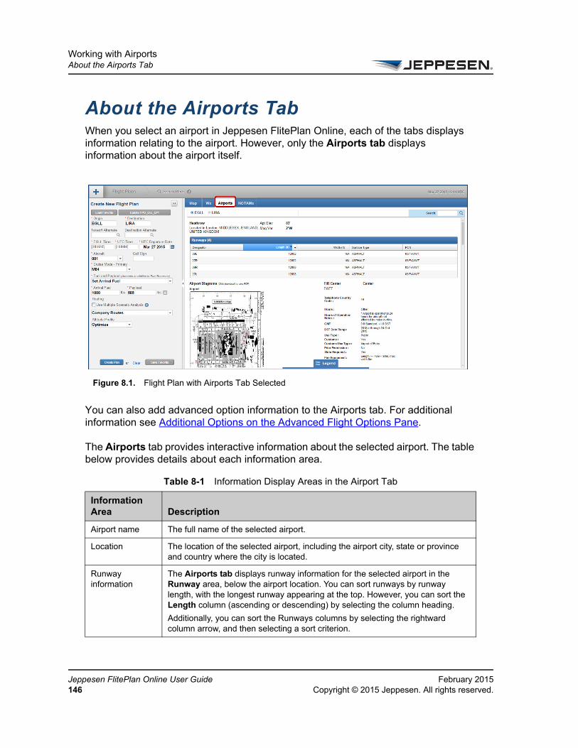
Working with AirportsAbout the Airports Tab
Je14
About the Airports TabWhen you select an airport in Jeppesen FlitePlan Online, each of the tabs displays information relating to the airport. However, only the Airports tab displays information about the airport itself.
You can also add advanced option information to the Airports tab. For additional information see Additional Options on the Advanced Flight Options Pane.
The Airports tab provides interactive information about the selected airport. The table below provides details about each information area.
Figure 8.1. Flight Plan with Airports Tab Selected
Table 8-1 Information Display Areas in the Airport Tab
Information Area Description
Airport name The full name of the selected airport.
Location The location of the selected airport, including the airport city, state or province and country where the city is located.
Runway information
The Airports tab displays runway information for the selected airport in the Runway area, below the airport location. You can sort runways by runway length, with the longest runway appearing at the top. However, you can sort the Length column (ascending or descending) by selecting the column heading.
Additionally, you can sort the Runways columns by selecting the rightward column arrow, and then selecting a sort criterion.
ppesen FlitePlan Online User Guide February 20156 Copyright © 2015 Jeppesen. All rights reserved.

Working with AirportsAbout the Airports Tab
FeCo
Runways Columns
Descriptions for each column in the Runways table are provided below:
Designator column - Displays the designator for each runway at the selected airport.
Surface Type column - Displays descriptions of the runway surface types at the selected airport.
PCN column - Displays the pavement classification numbers of the runways at the selected airport.
Length column - Displays the lengths of the runways at the selected airport.
Width column - Displays the widths of the runways at the selected airport.
Airport Diagrams Airport Diagrams are displayed in the in the Airports tab below Runways.
FIR Center The FIR center that encompasses the selected airport.
Center The U.S. Domestic File, only for airports in the U.S.
Telephone Country Code
The telephone number prefix of the country in which the selected airport is located.
Hours of Operation
The hours during which the selected airport is operating. If the airport has special restrictions on the hours of operation, Hours of Operation displays Other with a description in Hours of Operation Notes.
Hours of Operation Notes
Hours of Operation Notes appears only when Hours of Operation displays Other, explaining special restrictions for the hours of operation. For example, the hours of operation could be restricted by noise curfews or parking limitations.
Offset from GMT The standard conversion (in hours) used to offset from Greenwich Mean Time in the time zone where the selected airport is located. For time zones that observe Daylight Savings Time, both the standard conversion and the Daylight Savings Time conversion are displayed.
DST Date Range The date range for which Daylight Savings Time is in effect where the selected airport is located.
Use Type The type of flights for which the selected airport is used. For example, the use type may be public, military, or private.
Has Customs Displays whether or not the selected airport has customs, with Yes or No.
Customs Use Type
For U.S. airports, Customs Use Type displays the type of customs required to land at the selected airport, as follows:
User Fee Airport – This requires approval for arrival and reimbursement to the airport for the cost of processing the aircraft.
Landing Rights – This requires that you obtain permission to land.
Airport of Entry – Aircraft arriving at an international airport do not need to request permission to land. However, advance notice of arrival is required and notification requirements vary by airport.
Table 8-1 Information Display Areas in the Airport Tab
Information Area Description
bruary 2015 Jeppesen FlitePlan Online User Guidepyright © 2015 Jeppesen. All rights reserved. 147

Working with AirportsAbout the Airports Tab
Je14
Prior Permissions Required
Displays whether or not the selected airport requires prior permission, with Yes or No.
Slots Required Displays whether or not you are required to provide a slot time from ATC to land at the selected airport, with Yes or No.
Fire Equipment Description of the fire equipment available at the selected airport.
Distance to City Center
The distance from the selected airport to the center of the city where the airport is located.
Support Service Listing
Handlers area Names and contact information of Handlers for the selected airport.
Hotel area Names and contact information of Hotels near the selected airport.
Caterers area Names and contact information of Caterers for the selected airport.
Transportation area
Names and contact information of Transportation Companies for the selected airport.
Table 8-1 Information Display Areas in the Airport Tab
Information Area Description
ppesen FlitePlan Online User Guide February 20158 Copyright © 2015 Jeppesen. All rights reserved.

Working with AirportsViewing Fixed Airports
FeCo
Viewing Fixed AirportsYou can view airport information for airports that are associated with a computed flight plan, a flight that you are planning, or a favorite flight plan. These airports are considered fixed airports. Regardless of how you select your airports, their ICAO codes appear on the airports bar, located at the top of the tab.
Depending on the tab you have selected when you view a fixed airport, one of the following appears:
• If you select the Map tab, the map centers on the locations of the selected airports in the airport bar. Select or clear the check boxes at the top of the tab to view desired graphical weather info. See About the Map Tab for more information.
• If you select the Wx tab, weather information appears for each selected airport in the airport bar. Select or clear the check boxes at the top of the tab to view the types of textual weather info. See About the Wx Tab for more information.
• If you select the Airports tab, general information for the selected airports appears. The origin is the default selected airport. For an explanation of the Airports tab info, see About the Airports Tab.
• If you select the NOTAMs tab, NOTAMs and TFRs for the selected airports appear.
When you view airports associated with a computed flight plan, a flight you are planning, or a favorite flight plan, you can only view airport information for the origin, the departure, and the first five alternates. You do not see additional airports. Each option for viewing fixed airports is explained below.
To view airports on a computed flight plan
• On the Flight Plans navigation tab, select the computed flight plan you want to view in either the Active or the History pane.
The airports associated with the computed flight plan appears on the airports bar.
To view airports when planning a flight
• In the Create New Flight Plan pane, enter the airports you want to include in your flight plan, including any alternates.
As you add airports, each airport appears in the right pane.
bruary 2015 Jeppesen FlitePlan Online User Guidepyright © 2015 Jeppesen. All rights reserved. 149

Working with AirportsViewing Fixed Airports
Je15
To view airports on a flight plan favorite
• In the Create New Flight Plan pane, select Load Favorite.
The airports associated with the favorite appear on the airports bar.
ppesen FlitePlan Online User Guide February 20150 Copyright © 2015 Jeppesen. All rights reserved.

Working with AirportsSearching for Ad-Hoc Airports and Jeppesen Navigational Aids
FeCo
Searching for Ad-Hoc Airports and Jeppesen Navigational Aids
This search function allows you to search the Jeppesen aviation database for details of aviation/flight information for airports that are not part of flight plan(s), also called ad-hoc airports. The database information is revised every 28 days.
Depending on which tab you have open, you may be able to view information for only one selected airport at a time, or for all ad hoc and fixed airports at once.
To search for an ad hoc airport and related Jeppesen navaids, see Searching for Information.
1. Type two characters of the ICAO or IATA code, airport name, or airport city of the desired airport in the Search box at the right of the interface below the navigation bar.
2. Select the desired airport from the matches.
Figure 8.2. Searching for Airports and Jeppesen Navigational Aids
bruary 2015 Jeppesen FlitePlan Online User Guidepyright © 2015 Jeppesen. All rights reserved. 151

Working with AirportsSearching for Ad-Hoc Airports and Jeppesen Navigational Aids
Je15
3. Select the highlighted airport again to obtain a second level of details such as latitude and longitude.
Depending on which tab is selected, one of the following occurs:
• If the Map tab is selected, the map centers on the location of the airport. If you also have other airports selected, the map shows all selected airports. See About the Map Tab.
• If the Wx tab is selected, weather information appears for the airport. Select or clear the check boxes at the top of the tab to view the desired types of weather info. See About the Wx Tab
• If the Airports tab is selected, general information for the airport appears. For an explanation of the Airports tab info, see About the Airports Tab.
• If the NOTAMs/TFRs tab is selected, NOTAMs and TFRs for the selected airport appear. See About the NOTAMs Tab.
To remove an ad hoc airport:
• Below the navigation bar, select the minus (–) icon to the right of the airport you want to delete.
The ICAO code of the selected airport disappears, and the information for that airport disappears from the right pane.
You can remove only ad hoc airports in this way. Airports that are part of a flight plan or a favorite (fixed airports) can only be removed in the The Create New Flight Plan Pane.
ppesen FlitePlan Online User Guide February 20152 Copyright © 2015 Jeppesen. All rights reserved.

Working with AirportsSearching for Ad-Hoc Airports and Jeppesen Navigational Aids
FeCo
bruary 2015 Jeppesen FlitePlan Online User Guidepyright © 2015 Jeppesen. All rights reserved. 153


CHAPTER 9
Managing Weight and Balance
This section provides information about creating and managing weight and balance plans. The weight and balance functionality in Jeppesen FlitePlan Online enables you to enter and update data that defines weight and balance stations (Passenger, Cargo, Galley, Fuel), and identifies fuel tank specifications.
The Jeppesen weight and balance plan is a check and balance feature that enables a crew to review and, if necessary, prove that the planned flight weight conditions do not exceed the certified limitations of the aircraft.
Managing Weight and Balance consists of the following topics:
• About a Weight and Balance Plan
• About the Weight & Balance Interface
• Creating an Aircraft Weight and Balance Configuration
• Modifying an Aircraft Configuration
• Customizing the CG Envelope Diagram
• Working with a Load Plan
• Printing a Weight and Balance Plan
• Forwarding a Weight and Balance Plan
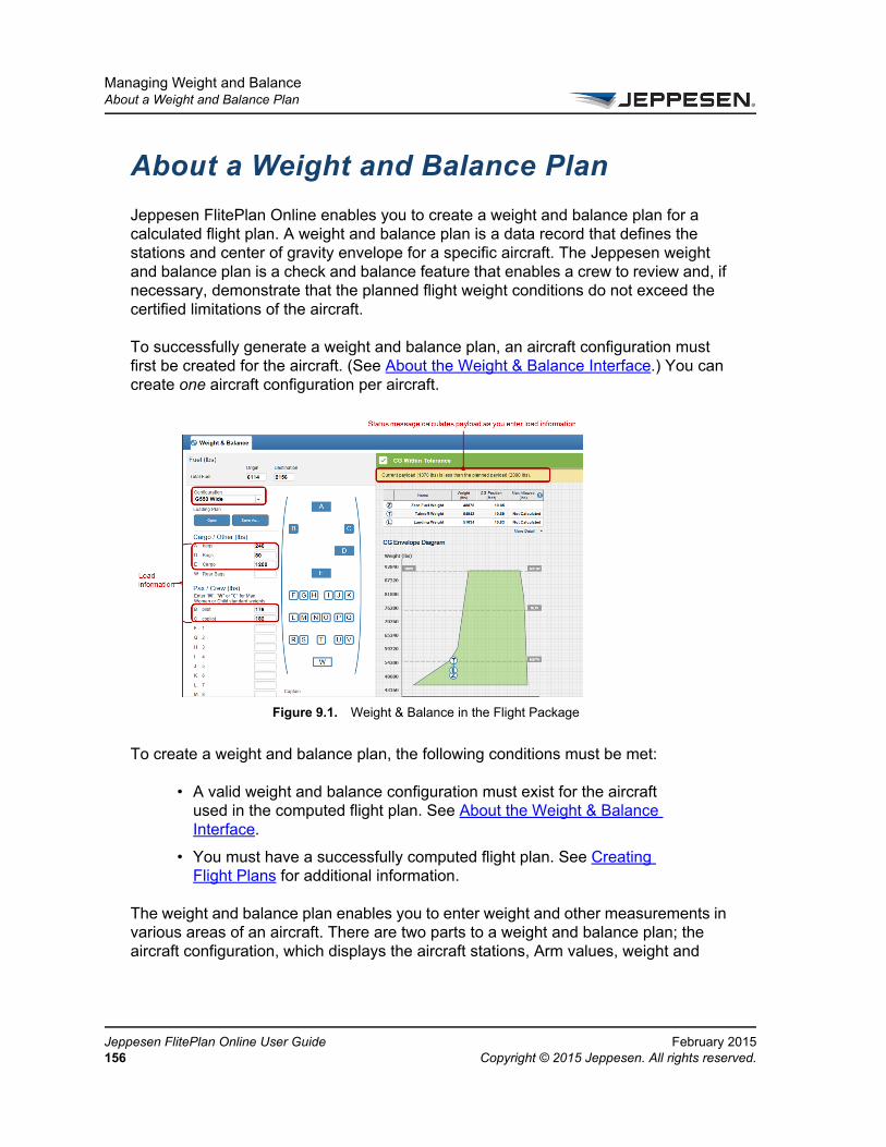
Managing Weight and BalanceAbout a Weight and Balance Plan
Je15
About a Weight and Balance Plan
Jeppesen FlitePlan Online enables you to create a weight and balance plan for a calculated flight plan. A weight and balance plan is a data record that defines the stations and center of gravity envelope for a specific aircraft. The Jeppesen weight and balance plan is a check and balance feature that enables a crew to review and, if necessary, demonstrate that the planned flight weight conditions do not exceed the certified limitations of the aircraft.
To successfully generate a weight and balance plan, an aircraft configuration must first be created for the aircraft. (See About the Weight & Balance Interface.) You can create one aircraft configuration per aircraft.
To create a weight and balance plan, the following conditions must be met:
• A valid weight and balance configuration must exist for the aircraft used in the computed flight plan. See About the Weight & Balance Interface.
• You must have a successfully computed flight plan. See Creating Flight Plans for additional information.
The weight and balance plan enables you to enter weight and other measurements in various areas of an aircraft. There are two parts to a weight and balance plan; the aircraft configuration, which displays the aircraft stations, Arm values, weight and
Figure 9.1. Weight & Balance in the Flight Package
ppesen FlitePlan Online User Guide February 20156 Copyright © 2015 Jeppesen. All rights reserved.

Managing Weight and BalanceAbout a Weight and Balance Plan
FeCo
balance configurations and the center of gravity (CG) Envelope Diagram, which is a graphical depiction of the center of gravity. See About the Weight & Balance Interface.
About the CG Envelope
The CG Envelope Diagram is a graph that plots weight on the vertical axis, and CG (center of gravity) or MAC% on the horizontal axis. FPO displays the CG position on the graphic using three weight values:
1 Zero Fuel weight—The total weight of the aircraft, passengers, baggage/cargo, and galley, excluding fuel weight.
2 Takeoff weight—The total weight of the aircraft, passengers, baggage/cargo, galley, and fuel remaining at liftoff.
3 Landing weight—The total weight of the aircraft, passengers, baggage/cargo, galley, and fuel remaining at touchdown.
bruary 2015 Jeppesen FlitePlan Online User Guidepyright © 2015 Jeppesen. All rights reserved. 157

Managing Weight and BalanceAbout the Weight & Balance Interface
Je15
About the Weight & Balance Interface The Weight & Balance plan is configured via a series of steps in which you enter values that define the center of gravity (CG) for your flight. Jeppesen FlitePlan Online produces the CG envelope for your flight when you have entered all required weight & balance configuration information.
About Weight & Balance InformationBelow you find descriptions for Weight & Balance options and functionality. If you wish to use a weight and balance configuration on a flight plan, you must create the configuration first. This section provides information to help you make decisions as you progress through the steps that are required to create the configuration.
For directions on creating a weight and balance configuration, see Creating an Aircraft Weight and Balance Configuration.
Weight and Balance Configuration Editing Tools
You can use the following editing tools that are available only when you are in one of the step tab panes to configure weight and balance:
Table 9-1. Weight and Balance Configuration Editing Tools
Option Description
New Create a new configuration and then advance to the next step.
Edit Modify the values within one or more steps and save your changes.
Duplicate Open a configuration, copy it, and save it with a different name.
Delete Delete one or more configurations.
Cancel Cancel your previous changes.
Exit Exit the weight and balance configuration pane and discard your changes. Alternatively, you can select Cancel to return to the previous action.
Save & Close Discard changes and close the pane.
ppesen FlitePlan Online User Guide February 20158 Copyright © 2015 Jeppesen. All rights reserved.

Managing Weight and BalanceAbout the Weight & Balance Interface
FeCo
The Weight & Balance Configuration Summary Page
This page provides information related to status and setup values in a table with the top row showing column headings and the remaining rows representing configuration data values. The values that appear here are set up in:
• Step 1: Configuration Setup Step
• Step 2: Stations
• Step 3: CG Envelope
The Complete/Incomplete status bar on the right graphically shows the status of the configuration. You can only use completed configurations.
• A complete configuration displays with no orange bar to the left and available editing tools on the right in the Actions column. A completed configuration indicates that all required fields have been completed and the CG envelope is finished.
For more information on the editing tools, see Weight and Balance Configuration Editing Tools. See also Modifying the Weight and Balance Configuration.
Figure 9.2. The Weight and Balance Configuration Summary Page
bruary 2015 Jeppesen FlitePlan Online User Guidepyright © 2015 Jeppesen. All rights reserved. 159

Managing Weight and BalanceAbout the Weight & Balance Interface
Je16
• An orange bar to the left of the configuration indicates one or more of the following conditions:
1 Required information is missing in one or more steps.
2 One or more steps are incomplete.
3 Partial changes have been saved for later completion.
Step 1: Configuration Setup Step
Add the general identification and measurements information that become part of the CG Envelope. The following tables describe the information you have to enter in the boxes.
Table 9-2 Columns in the Weight and Balance Configuration Summary Page
Column Heading Description
Aircraft Registration Number
Define this in Name in the Aircraft list in Step 1: Configuration Setup Step.
Configuration Name
Define this in the Configuration Name box in Step 1: Configuration Setup Step.
Aircraft Type Define this in Type in the Aircraft list in Step 1: Configuration Setup Step.
Last Updated (UTC)
UTC time when the configuration was most recently updated.
Updated By Login name of the person who last updated the configuration.
Actions This column contains tools that allow you to Edit, Duplicate, or Delete a configuration. See Weight and Balance Configuration Editing Tools.
Table 9-3 Information to Enter in Configuration Setup Step 1
Box Name Description
Aircraft Select the aircraft from the dropdown menu by Name and Type of aircraft.
Configuration Name Type in the configuration name.
Use as Default Configuration
Sets the current configuration to default for future weight and balance plans.
Station Arm Units Units of measure for Station Arm Units.
Fuel Volume Units Units of measure for Fuel Volume Units.
ppesen FlitePlan Online User Guide February 20150 Copyright © 2015 Jeppesen. All rights reserved.

Managing Weight and BalanceAbout the Weight & Balance Interface
FeCo
Step 2: Stations
The Stations pane provides information related to CG values organized by station type (Fuel and Non-fuel).
Non-fuel Stations are “seats” where passengers sit and “other” indicates any other position on the aircraft. Examples for “Other” stations include cargo, baggage, closets, galleys or any item located at a fixed position in the aircraft that is not a seat
The following table describes the information you have to enter in each box.
Standard Fuel Weight Jeppesen FlitePlan Online fills in the value in this box when you define the limit in Step 2: Stations. Use this if you want advisory volume limit messaging.
Vertical Units Related to the CG Envelope’s Vertical Weight Units for ARM values.
Horizontal Units Units of measure for the CG Envelope horizontal axis.
Corrected Empty Weight
The aircraft’s operating empty weight including the crew and crew supplies, removable service and emergency equipment, oil and usable fuel, and any other additional aircraft items that have a standard weight and position within the aircraft, minus the crew. Additionally, you can use the corrected empty weight to increase the efficiency of aircraft loading by adding any aircraft items that have a standard weight and position but are not part of the aircraft's operational empty weight. If you use the corrected empty weight to add items, you need to understand which items are already accounted for in the Corrected Empty Weight (CEW) value.
Corrected Empty ARM ARM value that correlates with the corrected empty weight--for example, the weight of the operating empty ARM of the aircraft adjusted for any additions or subtractions made to the operating empty weight of the aircraft.
Table 9-4 Information to Enter in Configuration Setup Step 2
Box Name Description
Fuel Station Define the ARM type, ARMs, and volume limits of fuel tanks.
Non Fuel Station Define the station type, ARM, weight limits and cabin position of passengers, cargo and other items loaded into the aircraft hull.
Station Arm Unit The unit of measure for measuring the distance from the reference datum to a given station.
Station Arm The distance from the reference datum to a given station.
Table 9-3 Information to Enter in Configuration Setup Step 1
bruary 2015 Jeppesen FlitePlan Online User Guidepyright © 2015 Jeppesen. All rights reserved. 161
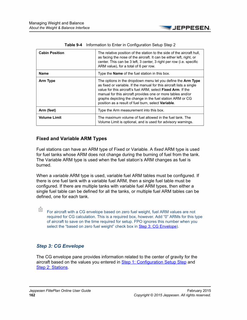
Managing Weight and BalanceAbout the Weight & Balance Interface
Je16
Fixed and Variable ARM Types
Fuel stations can have an ARM type of Fixed or Variable. A fixed ARM type is used for fuel tanks whose ARM does not change during the burning of fuel from the tank. The Variable ARM type is used when the fuel station’s ARM changes as fuel is burned.
When a variable ARM type is used, variable fuel ARM tables must be configured. If there is one fuel tank with a variable fuel ARM, then a single fuel table must be configured. If there are multiple tanks with variable fuel ARM types, then either a single fuel table can be defined for all the tanks, or multiple fuel ARM tables can be defined, one for each tank.
Step 3: CG Envelope
The CG envelope pane provides information related to the center of gravity for the aircraft based on the values you entered in Step 1: Configuration Setup Step and Step 2: Stations.
Cabin Position The relative position of the station to the side of the aircraft hull, as facing the nose of the aircraft. It can be either left, right, or center. This can be 3 left, 3 center, 3 right per row (i.e. specific ARM value), for a total of 6 per row.
Name Type the Name of the fuel station in this box.
Arm Type The options in the dropdown menu let you define the Arm Type as fixed or variable. If the manual for this aircraft lists a single value for this aircraft’s fuel ARM, select Fixed Arm. If the manual for this aircraft provides one or more tables and/or graphs depicting the change in the fuel station ARM or CG position as a result of fuel burn, select Variable.
Arm (feet) Type the Arm measurement into this box.
Volume Limit The maximum volume of fuel allowed in the fuel tank. The Volume Limit is optional, and is used for advisory warnings.
For aircraft with a CG envelope based on zero fuel weight, fuel ARM values are not required for CG calculation. This is a required box, however. Add “0” ARMs for this type of aircraft to save on the time required for setup. FPO ignores this number when you select the “based on zero fuel weight” check box in Step 3: CG Envelope).
Table 9-4 Information to Enter in Configuration Setup Step 2
ppesen FlitePlan Online User Guide February 20152 Copyright © 2015 Jeppesen. All rights reserved.

Managing Weight and BalanceAbout the Weight & Balance Interface
FeCo
These values are organized and displayed graphically in the CG Envelope Diagram. This pane has two tabs: CG Envelope and Limit Lines.
The following table describes the elements in the CG Envelope tab.
The following table describes the elements in the Limit Lines tab. You can review and modify Limit Lines for maximum Weights and Arm for takeoff and landing.
Modifying the Weight and Balance ConfigurationYou can edit, duplicate, or delete a configuration from the The Weight & Balance Configuration Summary Page. To perform each of these actions:
1. Select the configuration first in the page.
2. In the Actions column, perform one of the following actions:
1 Select Edit, Duplicate, or Delete, or, alternatively, select these items from the tool bar at the bottom of the page.
2 Change the values for each step that you wish to view and/or modify.
3 Confirm the changes if required.
4 Save & Close the pane.
3. To cancel previous changes to the configuration, select Cancel.
4. To exit the weight & balance configuration step, select Exit.
5. To advance to the next configuration step, select the button for the next step.
Table 9-5 Information to Enter in the CG Envelope Tab
Element Name Description
Based on Zero Fuel Weight Only check box
Base the CG calculations on zero fuel weight.
Weight (lbs) The vertical unit of measure from step 1.
Arm Enter the Arm to view the result in the horizontal axis.
Table 9-6 Information to Enter in the Limit Lines Tab
Element Name Description
Custom Labels The Name and Label boxes in the Limit Lines area allow you to create custom labels that are added to the CG Envelope Diagram.
bruary 2015 Jeppesen FlitePlan Online User Guidepyright © 2015 Jeppesen. All rights reserved. 163

Managing Weight and BalanceAbout the Weight & Balance Interface
Je16
Creating an Aircraft Weight and Balance Configuration
Use the weight and balance information from the aircraft manual to create the weight and balance configuration.
To create an aircraft weight and balance configuration
1. On the FlitePlan Online toolbar, select Settings.
2. From the Settings menu, select Weight & Balance Configuration.
The Weight & Balance Configuration summary page opens.
FlitePlan Online displays any existing configurations and marks the ones that are incomplete and cannot be used.
You do not see any configurations if none exist.
Figure 9.3. Weight & Balance Configuration Step
ppesen FlitePlan Online User Guide February 20154 Copyright © 2015 Jeppesen. All rights reserved.

Managing Weight and BalanceAbout the Weight & Balance Interface
FeCo
3. Select New.
The Step 1: Configuration Setup tab opens and displays General, Station Arm, CG Envelope Units and Empty Aircraft variable
values.
4. In the Aircraft box, type in the name of the aircraft or select one from the dropdown menu.
5. Type in the Configuration Name. An aircraft configuration name must be alphanumeric and can have a maximum of 36 characters.
6. Set the current configuration to Use as Default Configuration for future use if you like. The configuration you are currently working with is not available until you finish all the steps for it.
7. Select a unit from the following dropdown menus:
– Station Arm Units
– Fuel Volume Units
– Standard Fuel Weight
– Horizontal Units (vertical weight units are based on the aircraft’s profile)
8. Type in the Corrected Empty Weight.
9. Type in the Corrected Empty Arm.
Figure 9.4. Step 1: Configuration Step
bruary 2015 Jeppesen FlitePlan Online User Guidepyright © 2015 Jeppesen. All rights reserved. 165
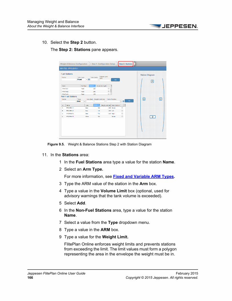
Managing Weight and BalanceAbout the Weight & Balance Interface
Je16
10. Select the Step 2 button.
The Step 2: Stations pane appears.
11. In the Stations area:
1 In the Fuel Stations area type a value for the station Name.
2 Select an Arm Type.
For more information, see Fixed and Variable ARM Types.
3 Type the ARM value of the station in the Arm box.
4 Type a value in the Volume Limit box (optional, used for advisory warnings that the tank volume is exceeded).
5 Select Add.
6 In the Non-Fuel Stations area, type a value for the station Name.
7 Select a value from the Type dropdown menu.
8 Type a value in the ARM box.
9 Type a value for the Weight Limit.
FlitePlan Online enforces weight limits and prevents stations from exceeding the limit. The limit values must form a polygon representing the area in the envelope the weight must be in.
Figure 9.5. Weight & Balance Stations Step 2 with Station Diagram
ppesen FlitePlan Online User Guide February 20156 Copyright © 2015 Jeppesen. All rights reserved.
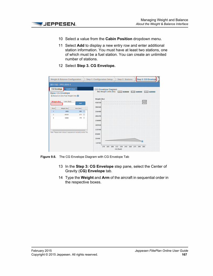
Managing Weight and BalanceAbout the Weight & Balance Interface
FeCo
10 Select a value from the Cabin Position dropdown menu.
11 Select Add to display a new entry row and enter additional station information. You must have at least two stations, one of which must be a fuel station. You can create an unlimited number of stations.
12 Select Step 3. CG Envelope.
13 In the Step 3: CG Envelope step pane, select the Center of Gravity (CG) Envelope tab.
14 Type the Weight and Arm of the aircraft in sequential order in the respective boxes.
Figure 9.6. The CG Envelope Diagram with CG Envelope Tab
bruary 2015 Jeppesen FlitePlan Online User Guidepyright © 2015 Jeppesen. All rights reserved. 167

Managing Weight and BalanceAbout the Weight & Balance Interface
Je16
15 Select Add to display a new entry row and enter additional weight information. You must enter at least three envelope points for each CG Envelope (with no limit on the total number that you can create, unless you need to create a polygon.)
12. Select the Limit Lines tab to view Maximum Weight Limits.
13. If necessary, type new values for the Weight and/or Arm.
1 Select Add to display a new entry row and enter the additional information.
2 Select Add again when you are done.
The CG Envelope Diagram area displays the envelope configuration as you enter the weight and ARM information.
Optionally, you can create Custom Labels that can be added to the CG Envelope Diagram.
Figure 9.7. The CG Envelope Diagram with Limit Lines Tab
ppesen FlitePlan Online User Guide February 20158 Copyright © 2015 Jeppesen. All rights reserved.
Managing Weight and BalanceAbout the Weight & Balance Interface
FeCo
14. Select Finish to save the aircraft weight & balance configuration.
Jeppesen FlitePlan Online checks to ensure that the mandatory information exists, saves the aircraft configuration, and displays a confirmation message.
Completed configurations are available in the Weight & Balance Configuration tab.
Modifying an Aircraft ConfigurationYou can rename an existing aircraft configuration, create custom labels, or make other changes, such as add a station or a CG envelope point.
To modify a saved configuration
1. From the Weight & Balance Configuration step, locate your configuration.
2. Select Actions > Edit.
3. Save your changes when you are done.
Customizing the CG Envelope DiagramYou can use custom labels and Conditional CG Envelopes to denote areas of the CG Envelope Diagram with text or numerals, or create a Conditional CG Envelope.
To create custom labels on the CG Envelope Diagram
1. From the main tool bar, select Settings > Weight & Balance.
2. From Weight & Balance Configuration Step 3: CG Envelope tab, select Limit Lines.
3. Select Add More. The Name field displays “New” with a sequential number representing the number of changes made.
Optionally, you may type any Name you wish into the Name field (22 Character Max) and any Label you wish directly into the Label field (5 character max).
If your information is incomplete, Jeppesen FlitePlan Online displays a message indicating that you need additional information to complete the plan.
bruary 2015 Jeppesen FlitePlan Online User Guidepyright © 2015 Jeppesen. All rights reserved. 169

Managing Weight and BalanceAbout the Weight & Balance Interface
Je17
Add points to the CG Envelope Diagram where the label is to be displayed.
Adding a Conditional CG Envelope to a Weight and Balance ConfigurationThe Conditional CG Envelope is displayed in the Flight Plan Package and Weight and Balance Configuration interface.
To add a Conditional CG Envelope to a Weight and Balance Configuration
1. From Weight & Balance Configuration Step 3: CG Envelope tab, select the CG Envelope tab.
2. Select Add Conditional CG Envelope.
In the Conditional CG Envelope Name field, “New” is displayed with a sequential number representing the number of changes made.
Optionally, you may type any Name you wish into the Name field (22 Character Max).
To view a Conditional CG Envelope Diagram in the Flight Package
1. Select Flight Plans.
2. Select the flight plan package to be viewed.
3. Select View Package.
4. In the Advanced Flight Options pane, select Edit (near Weight and Balance).
5. Select the configuration you wish to view.
The Conditional CG Envelope opens in the Flight Plan package.
Renaming an Aircraft Configuration1. On the toolbar, select the Settings button.
2. From the menu, select Aircraft Configuration.
The Weight & Balance Configuration step opens.
3. Select the aircraft configuration that you want to rename.
ppesen FlitePlan Online User Guide February 20150 Copyright © 2015 Jeppesen. All rights reserved.

Managing Weight and BalanceAbout the Weight & Balance Interface
FeCo
4. Select Edit.
A new navigation tab opens and displays the information for the aircraft configuration you selected.
5. In the Aircraft Configuration panel, in the Configuration Name box, type the new name for the aircraft configuration. An aircraft configuration name can have a maximum of 36 characters.
6. Select Save.
Adding a Station to an Aircraft Configuration1. On the toolbar, select the Settings button.
2. From the menu, select Aircraft Configuration.
The Weight & Balance Configuration navigation step opens.
3. Select the aircraft configuration to which you want to add a station.
4. Select Edit.
A new navigation tab opens and displays the information for the aircraft configuration you selected.
5. Enter the information on the Stations step.
A new station row appears.
6. Select a station type from the Station Type list. Options are Cargo, Fuel, Galley, and Seat.
7. Type a value in the Station Name box.
8. In the Arm Value box, type the ARM value of the basic aircraft weight.
9. Select Save.
Deleting an Aircraft Configuration1. On the toolbar, select the Settings button.
2. From the menu, select Aircraft Configuration.
The Weight & Balance Configuration navigation step opens.
3. Select the aircraft configuration that you want to delete.
bruary 2015 Jeppesen FlitePlan Online User Guidepyright © 2015 Jeppesen. All rights reserved. 171

Managing Weight and BalanceAbout the Weight & Balance Interface
Je17
4. Confirm the deletion before you Delete it.
5. Select OK.
Deleting a Station from an Aircraft Configuration1. On the toolbar, select the Settings button.
2. From the menu, select Aircraft Configuration.
The Weight & Balance Configuration navigation step opens.
3. Select the aircraft configuration that contains the station you want to delete.
4. Select Edit.
A new navigation step opens and displays the information for the aircraft configuration that you selected.
5. Select the minus (–) button next to the station that you want to delete.
A confirmation message appears to inform you that the selected station is about to be deleted from the current aircraft configuration.
6. Select OK.
The station is removed from the aircraft configuration.
Adding a CG Envelope Point to an Aircraft Configuration1. On the toolbar, select the Settings button.
2. From the menu, select Aircraft Configuration.
The Weight & Balance Configuration step pane opens.
3. Select the aircraft configuration to which you want to add a CG envelope point.
4. Select Edit.
A new navigation step opens and displays the information for the aircraft configuration that you selected.
5. Select the CG Envelope step.
6. Select Add More.
A new envelope point row appears.
7. Type a value in the Weight box.
ppesen FlitePlan Online User Guide February 20152 Copyright © 2015 Jeppesen. All rights reserved.
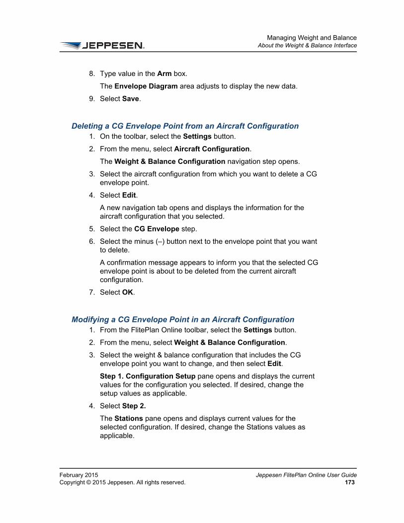
Managing Weight and BalanceAbout the Weight & Balance Interface
FeCo
8. Type value in the Arm box.
The Envelope Diagram area adjusts to display the new data.
9. Select Save.
Deleting a CG Envelope Point from an Aircraft Configuration1. On the toolbar, select the Settings button.
2. From the menu, select Aircraft Configuration.
The Weight & Balance Configuration navigation step opens.
3. Select the aircraft configuration from which you want to delete a CG envelope point.
4. Select Edit.
A new navigation tab opens and displays the information for the aircraft configuration that you selected.
5. Select the CG Envelope step.
6. Select the minus (–) button next to the envelope point that you want to delete.
A confirmation message appears to inform you that the selected CG envelope point is about to be deleted from the current aircraft configuration.
7. Select OK.
Modifying a CG Envelope Point in an Aircraft Configuration1. From the FlitePlan Online toolbar, select the Settings button.
2. From the menu, select Weight & Balance Configuration.
3. Select the weight & balance configuration that includes the CG envelope point you want to change, and then select Edit.
Step 1. Configuration Setup pane opens and displays the current values for the configuration you selected. If desired, change the setup values as applicable.
4. Select Step 2.
The Stations pane opens and displays current values for the selected configuration. If desired, change the Stations values as applicable.
bruary 2015 Jeppesen FlitePlan Online User Guidepyright © 2015 Jeppesen. All rights reserved. 173
Managing Weight and BalanceAbout the Weight & Balance Interface
Je17
5. Select Step 3.
The Basic CG Envelope pane opens.
6. If applicable, select the Based on Zero Fuel Weight Only check box.
7. If applicable, enter new values for the Weight and/or Arm boxes as needed and then select Add to create each new configuration.
8. If appropriate, select Limit Lines to view the Max Weight Limits (lbs) box.
– If desired, select Add More to create custom labels.
9. If applicable, select the check box for Max Take-Off Weight, Max Landing Weight, or Max Zero Fuel Weight to modify the limits by entering a new value in the Limit Lines.
10. Edit the CG envelope as necessary using the Basic CG Envelope pane using the Weights and /or Arm box(es).
11. Select Finish.
ppesen FlitePlan Online User Guide February 20154 Copyright © 2015 Jeppesen. All rights reserved.
Working with a Load PlanA load plan is a distribution of weight (station weight values) for a particular aircraft that you specify. Typically, you create a load plan during the weight and balance planning process. You are legally required to create a load plan for a flight. You can create one with Jeppesen FlitePlan Online or another tool.
Creating a New Load PlanYou must have the following to create a load plan:
• At least one customer aircraft available in Jeppesen FlitePlan Online.
• At least one weight and balance configuration available for the aircraft.
To create a new load plan
1. On the navigation bar, select Flight Plans.
2. In the Active pane, select the flight plan for which you want to create a new load plan.
3. Select View Package.
4. Select the Weight and Balance > Edit.
The Load Plan area appears in the left pane, and the right pane displays information about the CG envelope.
You can create a load plan before you create a flight plan by using the Payload Calculator. For more information about the Payload Calculator, see Completing Basic Flight Plan Information.
You can also work with load plans from the flight plan package. See Managing Flight Plan Packages.
Load plan names must be unique.
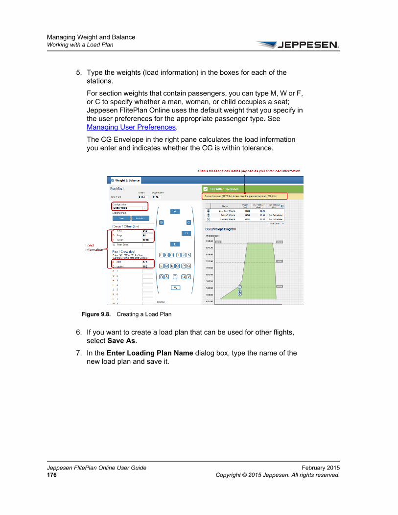
Managing Weight and BalanceWorking with a Load Plan
Je17
5. Type the weights (load information) in the boxes for each of the stations.
For section weights that contain passengers, you can type M, W or F, or C to specify whether a man, woman, or child occupies a seat; Jeppesen FlitePlan Online uses the default weight that you specify in the user preferences for the appropriate passenger type. See Managing User Preferences.
The CG Envelope in the right pane calculates the load information you enter and indicates whether the CG is within tolerance.
6. If you want to create a load plan that can be used for other flights, select Save As.
7. In the Enter Loading Plan Name dialog box, type the name of the new load plan and save it.
Figure 9.8. Creating a Load Plan
ppesen FlitePlan Online User Guide February 20156 Copyright © 2015 Jeppesen. All rights reserved.

Managing Weight and BalanceWorking with a Load Plan
FeCo
Viewing, Deleting, and Renaming a Load Plan
When you select a load plan to view, you can make changes to the plan, rename the plan, create a duplicate plan, or delete the plan. If you want to reuse a load plan for multiple flights, you can save that load plan and access it when planning another flight.
To view a load plan
1. On the navigation bar, select Flight Plans.
2. From the Active or History pane, select the flight plan whose load plan you want to view.
3. Select View Package.
4. Select Weight and Balance > Edit.
The Load Plan area appears in the right pane, and displays information about the selected flight plan, a load plan, and the CG envelope.
5. Select Open under Loading Plan.
6. Select the load plan that you want to view.
7. Select Load Selected.
FPO returns to the load plan and populates the section weights with the load plan that you selected.
To delete a load plan
1. Select the load plan as described in steps 1-6 above (viewing a load plan) to bring up the Load Plan dialog box. You can now delete or rename a load plan.
2. Select the minus (–) button next to the load plan.
3. Confirm the deletion.
bruary 2015 Jeppesen FlitePlan Online User Guidepyright © 2015 Jeppesen. All rights reserved. 177

Managing Weight and BalanceWorking with a Load Plan
Je17
To rename a load plan
1. Select and load the load plan as described in steps 1-7 in viewing a load plan.
2. Repeat step 7 from the list above.
Make changes to the plan (if needed) to save it as a different load plan.
3. Select Save As.
4. Save your plan after renaming it in the Enter Loading Plan Name dialog box.
Printing a Weight and Balance PlanYou can print a weight and balance plan as part of the flight plan package. For more information, see Printing a Flight Plan Package. Select the Weight and Balance check box to include weight and balance information in the printed flight plan package.
Forwarding a Weight and Balance PlanYou can forward a weight and balance plan as part of the flight plan package. For more information, see Sending a Flight Plan Package via Email. Select the Weight and Balance check box to include weight and balance information in the forwarded flight plan package.
Working with Weight and Balance in the Flight PlanYou can review and observe the following weight and balance values in the flight plan:
• Fuel values
• Remaining Fuel
• CG position
If you change any values in the displayed load plan, you must save it with a new name. Load plan names must be unique.
ppesen FlitePlan Online User Guide February 20158 Copyright © 2015 Jeppesen. All rights reserved.
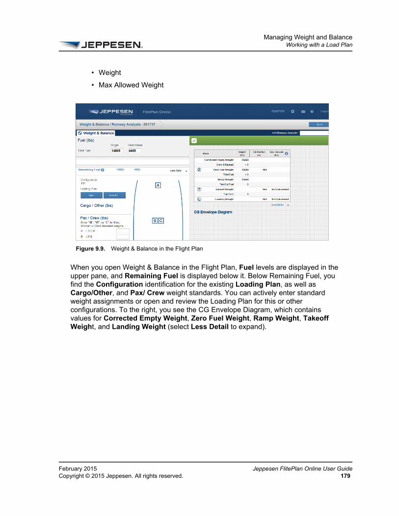
Managing Weight and BalanceWorking with a Load Plan
FeCo
• Weight
• Max Allowed Weight
When you open Weight & Balance in the Flight Plan, Fuel levels are displayed in the upper pane, and Remaining Fuel is displayed below it. Below Remaining Fuel, you find the Configuration identification for the existing Loading Plan, as well as Cargo/Other, and Pax/ Crew weight standards. You can actively enter standard weight assignments or open and review the Loading Plan for this or other configurations. To the right, you see the CG Envelope Diagram, which contains values for Corrected Empty Weight, Zero Fuel Weight, Ramp Weight, Takeoff Weight, and Landing Weight (select Less Detail to expand).
Figure 9.9. Weight & Balance in the Flight Plan
bruary 2015 Jeppesen FlitePlan Online User Guidepyright © 2015 Jeppesen. All rights reserved. 179

Managing Weight and BalanceWorking with a Load Plan
Je18
ppesen FlitePlan Online User Guide February 20150 Copyright © 2015 Jeppesen. All rights reserved.
CHAPTER 10
Requesting Multiple Scenario Analysis
Jeppesen’s Multiple Scenario Analysis uses the following routes:
• Optimized
• Recently Cleared Routes
• EUROCONTROL Proposed Routes
This section consists of the following topics:
• About Multiple Scenario Analysis
• About the Multiple Scenario Analysis Interface
• Working with Multiple Scenario Analysis

Requesting Multiple Scenario AnalysisAbout Multiple Scenario Analysis
Je18
About Multiple Scenario AnalysisWhen you use Multiple Scenario Analysis, Jeppesen FlitePlan Online calculates multiple routing options for your aircraft. The options that are available depend on the way in which your Jeppesen account is configured, as well as the origin, destination, aircraft and time of request.
Potential route options are:
• Recently Cleared Routes
• High Altitude Jet Airways
• Preferred Routes
• Company Routes
• Organized Tracks
The number and complexity of routes returned affects the response time for results.
ppesen FlitePlan Online User Guide February 20152 Copyright © 2015 Jeppesen. All rights reserved.

Requesting Multiple Scenario AnalysisAbout Multiple Scenario Analysis
FeCo
About the Multiple Scenario Analysis InterfaceWhen you select the Use Multiple Scenario Analysis check box on The Create New Flight Plan Pane, you see the Multiple Scenario Analysis (MSA) interface directly after you select Create Plan.
Figure 10.1. The Multiple Scenario Analysis Interface
bruary 2015 Jeppesen FlitePlan Online User Guidepyright © 2015 Jeppesen. All rights reserved. 183
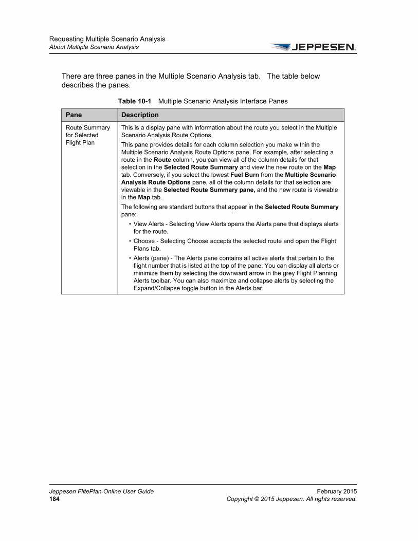
Requesting Multiple Scenario AnalysisAbout Multiple Scenario Analysis
Je18
There are three panes in the Multiple Scenario Analysis tab. The table below describes the panes.
Table 10-1 Multiple Scenario Analysis Interface Panes
Pane Description
Route Summary for Selected Flight Plan
This is a display pane with information about the route you select in the Multiple Scenario Analysis Route Options.
This pane provides details for each column selection you make within the Multiple Scenario Analysis Route Options pane. For example, after selecting a route in the Route column, you can view all of the column details for that selection in the Selected Route Summary and view the new route on the Map tab. Conversely, if you select the lowest Fuel Burn from the Multiple Scenario Analysis Route Options pane, all of the column details for that selection are viewable in the Selected Route Summary pane, and the new route is viewable in the Map tab.
The following are standard buttons that appear in the Selected Route Summary pane:
• View Alerts - Selecting View Alerts opens the Alerts pane that displays alerts for the route.
• Choose - Selecting Choose accepts the selected route and open the Flight Plans tab.
• Alerts (pane) - The Alerts pane contains all active alerts that pertain to the flight number that is listed at the top of the pane. You can display all alerts or minimize them by selecting the downward arrow in the grey Flight Planning Alerts toolbar. You can also maximize and collapse alerts by selecting the Expand/Collapse toggle button in the Alerts bar.
ppesen FlitePlan Online User Guide February 20154 Copyright © 2015 Jeppesen. All rights reserved.

Requesting Multiple Scenario AnalysisAbout Multiple Scenario Analysis
FeCo
About Sorting MSA Route Options Columns
For each column, you can sort the displayed information in ascending or descending order. You can also:
• Configure (a custom) Sort
• Auto Fit All Columns
• Auto Fit (the selected column)
• Group by Route
Multiple Scenario Analysis Route Options
This pane provides information about potential options for the route including Route identification, Estimated time Enroute (ETE), Fuel Burn, Flight Level (FL) and Distance. You can use this information to analyze various Multiple Scenario Analysis options.
Select a route from the list in the Multiple Scenario Analysis Route Options dropdown menu, and then view the route details in the Route Summary pane. You can also view the route in the Map and see changes as you select different options.
A brief description of each column in the table in the Multiple Scenario Analysis Route Options pane follows.
• Route - Routes that have recently become available for use and when they were cleared. The Route column also includes:
High Altitude Jet Airways - Indicates that these are airways for flights traveling between 18,000 feet (5,486 m) to 35,000 feet (10,668 m).
Best Company Route - Indicates that this route qualifies as the best flight route from all of your Company Routes. The Best Company Route option only appears when you have stored company routes for that city pair (origin and destination).
• ETE - Estimated Time Enroute for the selected route.
• Fuel Burn - Fuel burn for the route.
• FL - Flight Level.
• Distance - Distance to the point of arrival.
You can choose sorting options for each column by selecting the downward arrow in the dropdown menu for each box. See About Sorting MSA Route Options Columns.
Table 10-1 Multiple Scenario Analysis Interface Panes
Pane Description
bruary 2015 Jeppesen FlitePlan Online User Guidepyright © 2015 Jeppesen. All rights reserved. 185
Requesting Multiple Scenario AnalysisAbout Multiple Scenario Analysis
Je18
Working with Multiple Scenario Analysis
The procedures that follow provide step-by-step instructions for working with Multiple Scenario Analysis.
1. In The Create New Flight Plan Pane Routing area, select the Use Multiple Scenario Analysis check box to calculate multiple routing options.
The Multiple Scenario Analysis tab opens displaying information about potential routes. For additional information see About the Multiple Scenario Analysis Interface.
– To view route details:
From the Multiple Scenario Analysis Route Options pane, select each option you want to review. The Selected Route Summary pane displays the column details for the selected route (or any other column) and the Map displays the route graphically.
– To view alerts:
From the Selected Route Summary pane, select View Alerts. The Alerts pane opens, displaying a list of alerts for the selected routes.
– To print or close alerts:
From the alerts pane, select Print, or, alternatively, select Close to exit the Alerts pane.
– To accept a route:
Select the Choose button in the Selected Route Summary pane.
– To use column functions:
Select the arrow for any column heading (hover over the column to view the arrow). The Column function menu opens. Select any function from the menu to execute it for the selected column (unless designated as “All.”) See About Sorting MSA Route Options Columns.
Column functions designated as “All” are applied to all columns.
ppesen FlitePlan Online User Guide February 20156 Copyright © 2015 Jeppesen. All rights reserved.

CHAPTER 11
Requesting Dynamic Runway Analysis
This section describes the Dynamic Runway Analysis (DRA) functionality in Jeppesen FlitePlan Online.
This section consists of the following topics:
• About Dynamic Runway Analysis
• Using the Dynamic Runway Analysis Pane
Runway Analysis is limited to certain types of aircraft. If your aircraft does not meet the requirements to use DRA, you neither see nor are able to access the features and functionality described in this section. For additional information, please contact your Jeppesen account manager.

Requesting Dynamic Runway AnalysisAbout Dynamic Runway Analysis
Je18
About Dynamic Runway Analysis
DRA allows the pilot to monitor and quickly decipher runway conditions in order to assure that the aircraft does not exceed its capabilities during departure, takeoff and landing. To do this, DRA supplies on-screen data for factors like weather, weight, wind speed, pressure, temperature and runway length and to calculate how close the aircraft would be to approaching its limits for the selected runway(s). You can then make adjustments to avoid potential risks during takeoff, landing, and when considering shortening the runway. The Weight & Balance/Runway Analysis tab displays at the top of the window. The selected airports are displayed below the Weight & Balance/Runway Analysis table.
After you have accessed DRA from the flight plan, the Weight & Balance/Runway Analysis tab opens, displaying the following areas that can be used to review and modify runway analysis options.
About Calculating Runway AnalysisFPO starts the runway analysis calculations after you select Calculate on the Weight & Balance / Runway Analysis page.
Selecting Calculate instructs FPO to perform runway analysis computations for the selected runways, aircraft settings, and weather conditions. When FPO returns the calculations, you will see that the output includes limiting weights and Vspeeds for the selected weather conditions and default increments.
Using the Dynamic Runway Analysis Pane
To access Dynamic Runway Analysis:
1. Open an existing flight plan or create a new one.
2. In the flight plan details pane, select View Package.
The Flight Plan Package opens.
ppesen FlitePlan Online User Guide February 20158 Copyright © 2015 Jeppesen. All rights reserved.
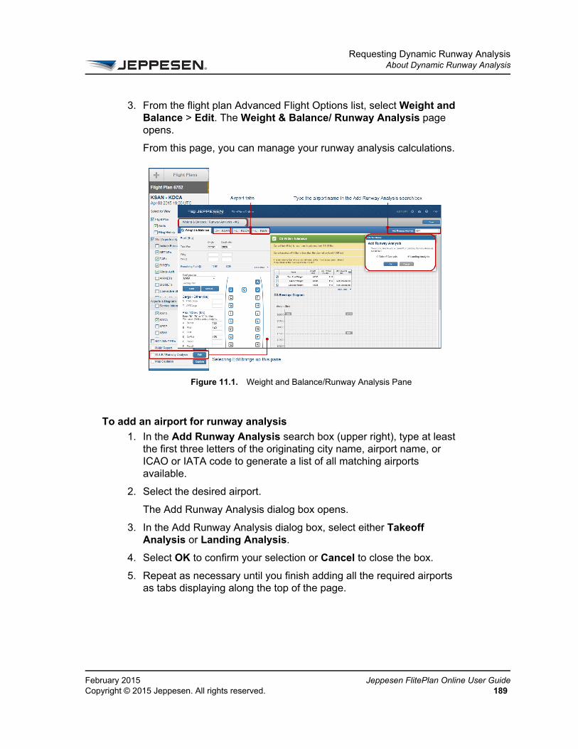
Requesting Dynamic Runway AnalysisAbout Dynamic Runway Analysis
FeCo
3. From the flight plan Advanced Flight Options list, select Weight and Balance > Edit. The Weight & Balance/ Runway Analysis page opens.
From this page, you can manage your runway analysis calculations.
To add an airport for runway analysis
1. In the Add Runway Analysis search box (upper right), type at least the first three letters of the originating city name, airport name, or ICAO or IATA code to generate a list of all matching airports available.
2. Select the desired airport.
The Add Runway Analysis dialog box opens.
3. In the Add Runway Analysis dialog box, select either Takeoff Analysis or Landing Analysis.
4. Select OK to confirm your selection or Cancel to close the box.
5. Repeat as necessary until you finish adding all the required airports as tabs displaying along the top of the page.
Figure 11.1. Weight and Balance/Runway Analysis Pane
bruary 2015 Jeppesen FlitePlan Online User Guidepyright © 2015 Jeppesen. All rights reserved. 189
Requesting Dynamic Runway AnalysisAbout Dynamic Runway Analysis
Je19
The Weight and Balance pane shows the items in the table below.
About the Runway Analysis Calculation SelectionsThe Weight & Balance / Runway Analysis page has the following areas where you can select the items that you want to include in your calculations.
Configuration Area
The Configuration area allows you to change runway analysis values for variable configuration fields. All configuration options have an effect on the nature of the calculations. These fields display configuration analysis using values that are set up by Jeppesen.
Table 11-1 Interface Elements in the Weight and Balance / Runway Analysis Pane
Element Description
Add Runway Analysis
FPO presents Runway Analysis tabs for Origin, Destination, and first destination alternate airports for which runway analysis is available. You can also add airports for runway analysis. For additional information see: For additional information see: To add an airport for runway analysis
Airport tabs Selected airports appear in separate tabs and the Runways table (which allows you to adjust takeoff and landing calculations).
Landing/Takeoff Runway selection
This table is located directly below the Add Runway Analysis toolbar, and is populated with runway data for the selected airport. These are the column headings in the table:
• Runway
This column displays the runway identification.
• LDA/TORA (ft)
This column displays the Landing Distance Available (LDA) or Take Off Runway Available (TORA) in feet for the runway in the same row.
• Shorten Available Length (ft)
This column allows you to run calculations using a shorter runway.
ppesen FlitePlan Online User Guide February 20150 Copyright © 2015 Jeppesen. All rights reserved.

Requesting Dynamic Runway AnalysisAbout Dynamic Runway Analysis
FeCo
Weather Area
Beneath the Configuration area is the Weather area, which is populated from the most current METAR information available. In this area you can also view information about the date and time weather was last updated. You can also update the weather or make adjustments. For example, based on weather forecasts, you may wish to adjust the settings.
If METAR data is unavailable, the fields are empty.
1. Select the refresh button (right) to refresh weather data.
2. Select the Detailed Wx button to view METAR and TAF statistics.
The table below describes each of the METAR variable configuration fields located under the METAR heading:
Shortening a RunwayYou can choose to shorten runways for arrival or departure airports.
To shorten a runway
1. Select the airport tab for the runway you want to shorten.
2. In the Shorten Available Length (ft) column, select the downward arrow.
3. Select Approach or Departure, and then select the value by which you wish to shorten the runway, not exceeding the runway length.
After you type in new values, FPO displays the adjusted fields to the right.
Table 11-2 Configurable METAR Boxes
Box Description
Wind (mag) Type a variable directly into this field to change this value.
Speed (KT) Select he plus (+) or minus (-) button to change this value.
Temp (C) Select the plus (+) or minus (-) button to change this value.
QNH (inHg) This value can also be labeled in Hg or in mbar, based on the selected airport. Select the plus (+) or minus (-) button to change this value.
bruary 2015 Jeppesen FlitePlan Online User Guidepyright © 2015 Jeppesen. All rights reserved. 191

Requesting Dynamic Runway AnalysisAbout Dynamic Runway Analysis
Je19
4. Select the Runway check boxes again to clear all selected values if you like.
5. Select Calculate.
Cancelling or Recalculating Takeoff Weight
To cancel or recalculate planned takeoff weight
• Change an input value (for example, Weather, Config, or Runway) and then select Calculate again
When you are completely finished with all your runway analysis, select Done to return to the flight package view.
If you have made changes, FPO asks you to confirm that you want to use the changed values or revert to the old values. Select Submit to use the new values and then select Done.
In your flight plan package, you see the flight plan summary, runway analysis, and weight and balance information with the Runway Analysis results table displayed at the bottom of the page.
Figure 11.2. Runway Analysis Selections to Calculate (Landing Runway Example)
ppesen FlitePlan Online User Guide February 20152 Copyright © 2015 Jeppesen. All rights reserved.

CHAPTER 12
Managing User Profiles and Preferences
This section describes how to create and manage your user profile and user preferences. The topics in this section include:
• Managing User Profiles
• Managing User Preferences

Managing User Profiles and PreferencesManaging User Profiles
Je19
Managing User Profiles
The profile information in FPO provides personal and company information about the user currently logged in, including name and contact information. When you first log in to FPO, your account displays default entries in the profiles screen.
The information you see for your account is individual user information and company/operator information that was entered when a Jeppesen account manager set up your profile. Some of the information is inaccessible to you and can only be changed by an administrator.
To edit your user profile
1. On toolbar at the top of the window, select the Settings button.
2. On the menu, select Edit User Profile.
The User Profile dialog box appears.
3. Enter your information for the following options:
• Alternate email address
• Street 1
• Street 2
• Street 3
• City
• State/Province
• Postal Code
• Country
• Contact Telephone Number
• Personnel Type
4. Select Save to apply the changes to your profile.
FPO returns to the main window and a message at the bottom of the window displays the number of changes made to the user profile.
ppesen FlitePlan Online User Guide February 20154 Copyright © 2015 Jeppesen. All rights reserved.

Managing User Profiles and PreferencesManaging User Preferences
FeCo
Managing User Preferences
The preferences information in Jeppesen FlitePlan Online provides various settings for flight plan calculation options, display options, or feature options. Preferences enable you to specify settings that are unique to your operational requirements. When you first log in to Jeppesen FlitePlan Online, your account displays default entries in the user preferences screen.
To edit your user preferences:
1. From the tool bar, select Settings >Edit User Preferences.
The User Preferences dialog box displays default entries in the boxes.
2. In the General area, select a Date Format. Options are:
• dd Mmm YYYY
• Mmm dd YYYY
3. In the Alternate Search Criteria area, select a value for the Initial Distance from Destination in nautical miles (nm). Options are:
• 25, 50, 75, 100, 150, 200, 250, 300 or 400.
4. Select a value for the Minimum Runway Length in feet (ft). Options are:
• 2000, 3000, 4000, 5000, 6000, 7000, or 8000.
5. Select one or more Airport Types. Options are:
• Civil/Public, Military and Joint (Civil/Public/Military).
6. Select a preference for Approach Types. Options are:
• Select Prefer ILS capable to request only those airports that are ILS capable.
• Clear Prefer ILS to request all airports.
7. Select a preference for Customs service. Options are:
• Select Prefer Customs services to request only those airports that have Customs services.
• Clear Prefer Customs services to request all airports.
8. In the Weight and Balance area, select a Weight Units of Measure. Options are:
• LB or KG
bruary 2015 Jeppesen FlitePlan Online User Guidepyright © 2015 Jeppesen. All rights reserved. 195

Managing User Profiles and PreferencesManaging User Preferences
Je19
9. Enter an integer value for these boxes:
• Standard Weight of Male
• Standard Weight of Female
• Standard Weight of Child
10. In the Wind Data Source area, select a data source. Options are:
• U.S. National Weather Service, Aviation Digital Format, or UK Meteorological Office.
11. In the Fuel Reserve Policy area, select a reserve policy. Options are:
• No Reserve, Domestic, Island, International, or International Reserve Overrides.
12. Select a Fuel Reserve Time in UTC format.
13. In the ENROUTE Alternates section select an Enroute Alternate (for oceanic flights). Options are:
• Exclude ETOPS
• Include ETOPS
14. In the Runway Analysis - Increments and Steps section, select a Wind Speed Increment (kts). Options are:
• Any integer from one through ten.
15. Select a Wind Speed Step(s). Options are:
• None, 1 above/1below, 2 above/2below.
16. Select Temperature Increments (C). Options are:
• Any integer from one through ten.
17. Select Temperature Steps. Options are:
• None, 1 above/1 below, 2 above/2 below.
18. Save your changes.
ppesen FlitePlan Online User Guide February 20156 Copyright © 2015 Jeppesen. All rights reserved.