fpga climatic oana valentina rusu advisor: lecturer eng. adrian-vasile duka phd “petru maior”...
TRANSCRIPT
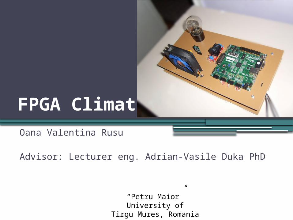
FPGA ClimaticOana Valentina Rusu Advisor: Lecturer eng. Adrian-Vasile Duka PhD
“Petru Maior” University ofTirgu Mures, Romania

Contents
•Introduction•Project overview•HDL Design•Software Design•Conclusions•Demo

Introduction
•It is a climate control platform based on FPGA.
•Replaces the two devices used to control the heating and cooling system ( the thermostat and the AC remote control )
•All available commands and menus are shown on a screen.

Why this project?
•Learn something new.
•Discover the usage and capabilities of an FPGA starting from simple to complex projects.
•Designing an useful platform for everyday use.

System Specification
•Allows to read temperature;•Current temperature is displayed on a
7segment display;•Allows to control the heating and cooling
systems;•It has an improved user interface ( it
displays an interactive menu on the screen );
•Commands are sent through a remote control;
•The controlling algorithms and the menu design were implemented on an integrated soft core;

Project overview
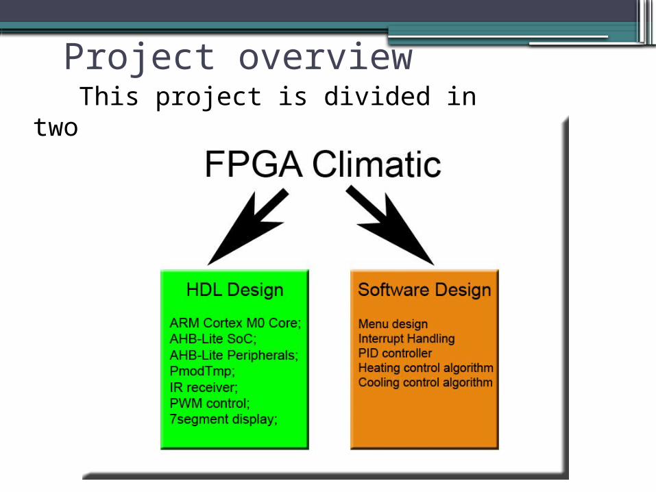
Project overview This project is divided in two parts:

HDL DesignSystem architecture:
AHB_Lite_SoC - the SoC based on the AHB-Lite protocol (implements the control logic, user interface etc.)IRReceiver - decodes the remote control signal and encodes the desired keys;PmodTMP - converts and reads the temperature from the temperature sensor;temp_7seg_display - displays the temperature on a 7 segment display;PWM – generates the PWM control signal;
PmodTMP module
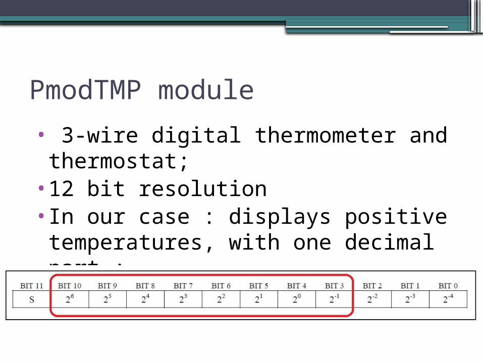
• 3-wire digital thermometer and thermostat;
•12 bit resolution•In our case : displays positive temperatures, with one decimal part ;

PModTmp State Machine
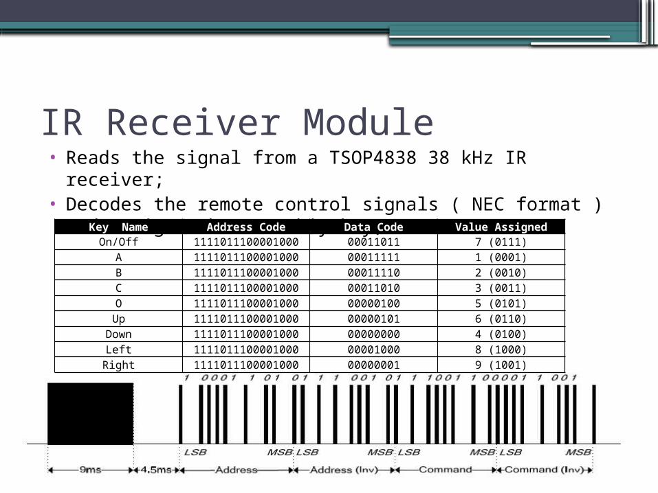
IR Receiver Module• Reads the signal from a TSOP4838 38 kHz IR receiver;• Decodes the remote control signals ( NEC format ) and
assigns them a 4-biy key;Key Name Address Code Data Code Value Assigned
On/Off 1111011100001000 00011011 7 (0111)
A 1111011100001000 00011111 1 (0001)
B 1111011100001000 00011110 2 (0010)
C 1111011100001000 00011010 3 (0011)
O 1111011100001000 00000100 5 (0101)
Up 1111011100001000 00000101 6 (0110)
Down 1111011100001000 00000000 4 (0100)
Left 1111011100001000 00001000 8 (1000)
Right 1111011100001000 00000001 9 (1001)

IR Receiver State Machine
PWM Module
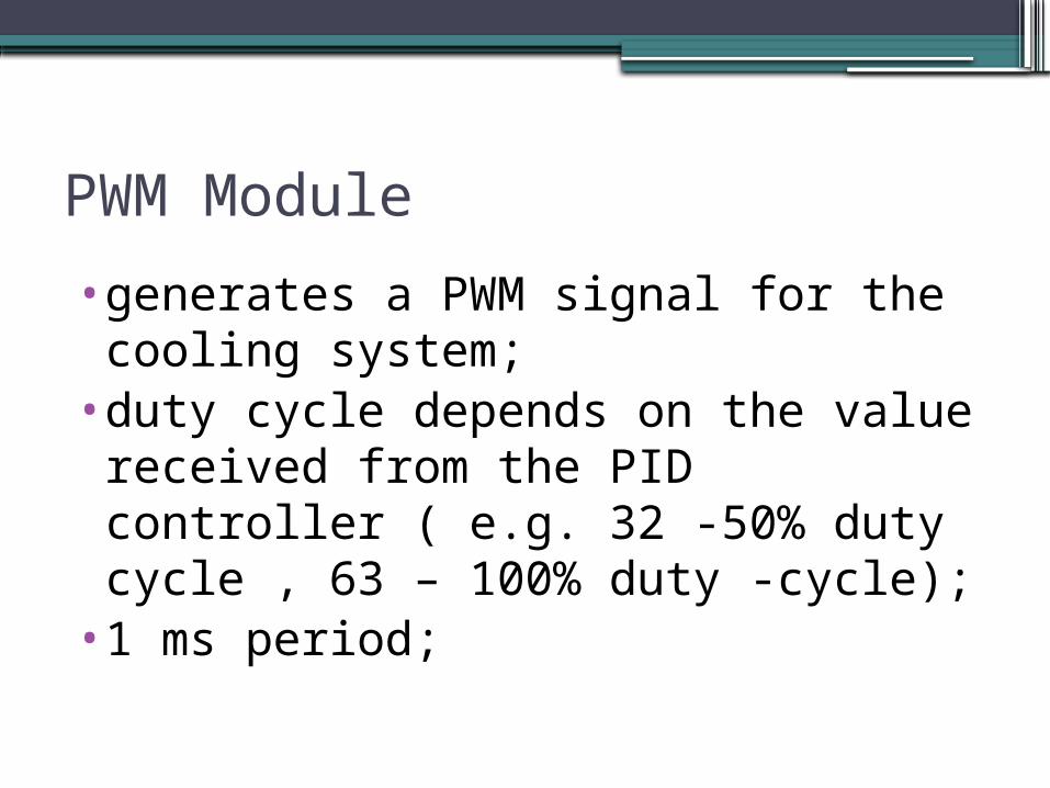
•generates a PWM signal for the cooling system;
•duty cycle depends on the value received from the PID controller ( e.g. 32 -50% duty cycle , 63 – 100% duty -cycle);
•1 ms period;

Temp_7seg_display module
•Shows the current temperature on a 7segment display;

Bin2bcd logic

AHB- Lite Protocol
•It is used in SoC designs as the on-chip bus.
•It is a subset of AHB protocol defined in the AMBA 3 standard;
•It simplifies the design for a bus with a single master;
•Main components: master component , slave components , address decoder , multiplexor;
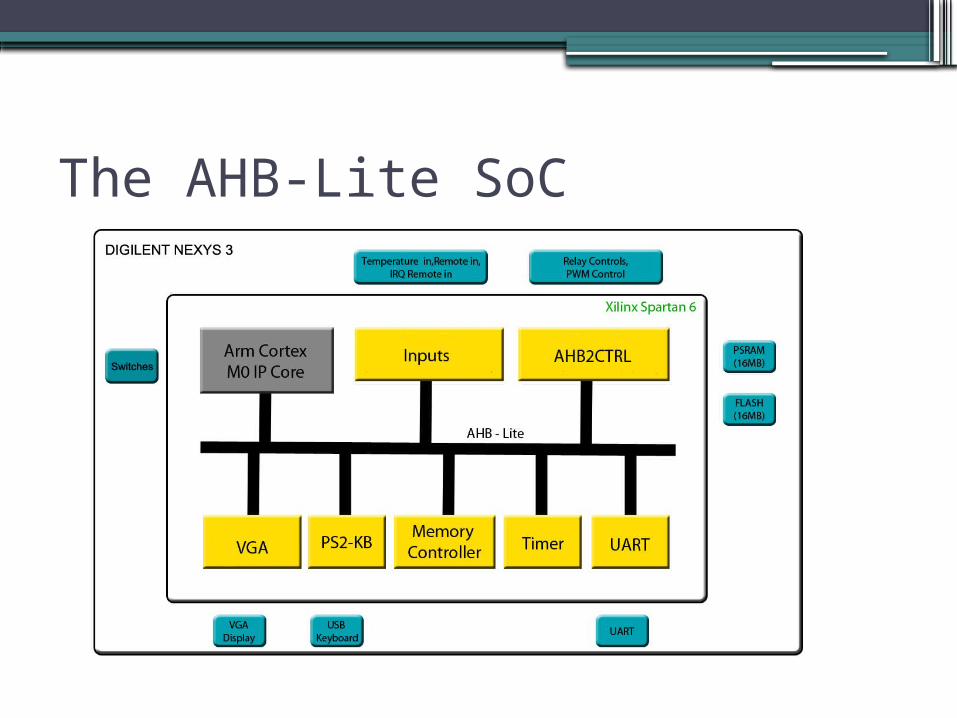
The AHB-Lite SoC

AHB-Lite Master: Cortex M0 Design Start• Based on a simplified version of the ARM
Cortex M0 processor;• It has a NVIC Interrupt controller with 16
Interrupt lines;• Supports 16 and 32 bit instructions;•Microcontroller-oriented processor for
MCU and SoC applications;

AHB-Lite Slaves – AHB2CTRL
•AHB2CTRL - slave module which receives data from the master module :
always @(posedge HCLK or negedge HRESETn) begin if(!HRESETn) rCTRL <= 8'b0000_0000; else if(rHSEL & rHWRITE & rHTRANS[1]) rCTRL <= HWDATA[7:0];
•and assigns it to the output wires:assign CTRL = rCTRL;

AHB-Lite Slaves - AHBINPUT• AHBINPUTS - slave module which reads data
from inputs :always @(posedge HCLK, negedge HRESETn) begin if(!HRESETn) input_data <= 16'h0000; else input_data <= INPUTSIN; end
• and it sends to the master:assign HRDATA[15:0]=input_data;
• Input data:irq_remote – irq signal, remote_code[3:0] - data, temperature[7:0]

AHB-Lite Slaves – VGA ControllerModifications:•Invisible cursor;•Custom cursor repositioning – for clear_screen() function;
•Modifying screen tiles and color text;
clear_screen() function
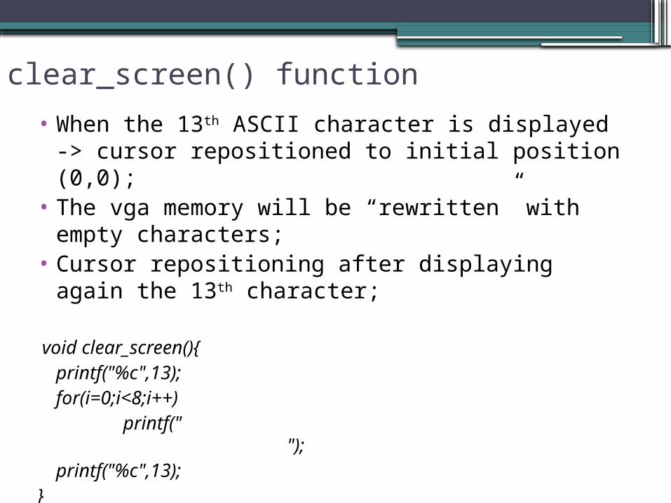
• When the 13th ASCII character is displayed -> cursor repositioned to initial position (0,0);
• The vga memory will be “rewritten” with empty characters;
• Cursor repositioning after displaying again the 13th character;
void clear_screen(){printf("%c",13);for(i=0;i<8;i++)
printf(" ");printf("%c",13);
}
Software DesignThe software component is written in ANSI C and
ARM Assembly. The project itself contains 4 files:• CM0-DS.h – contains the peripheral memory map
;• retarget.c – contains the implementation of
functions used to display the text;• cm0dsasm.s – contains instructions which handle
the interrupt vector;• MyProgram.c - contains the code used for menu
display and control algorithms;
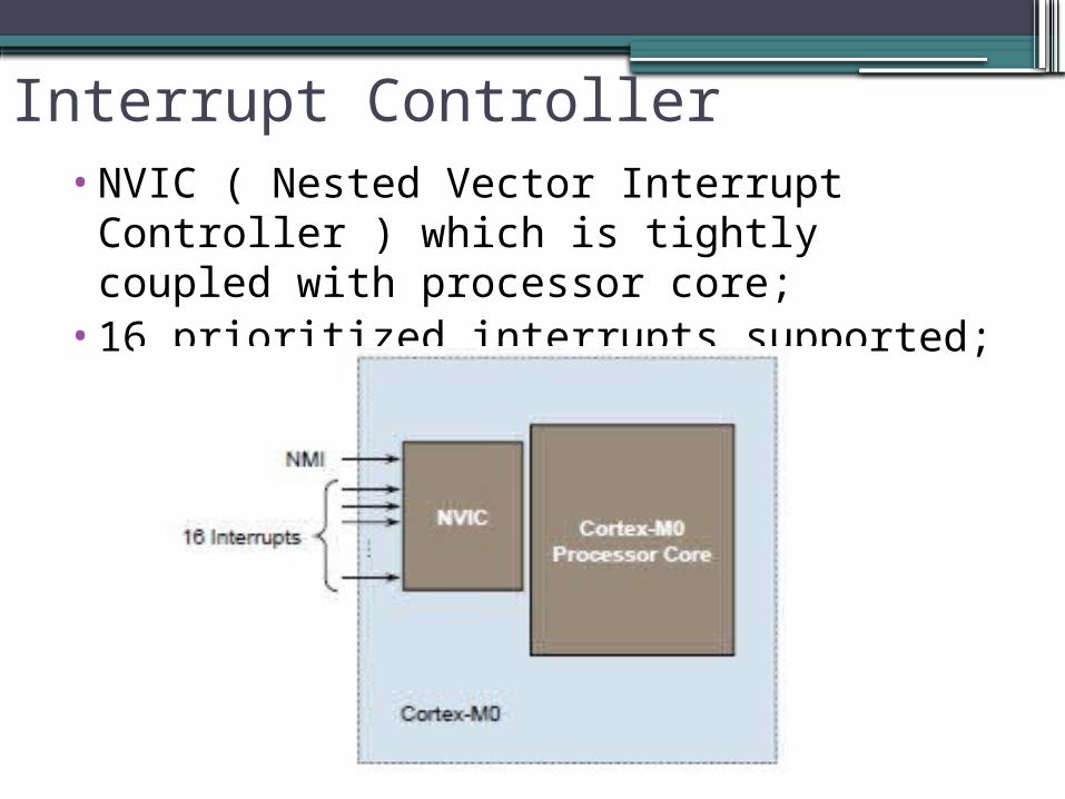
Interrupt Controller•NVIC ( Nested Vector Interrupt Controller
) which is tightly coupled with processor core;
•16 prioritized interrupts supported;

Interrupt Handling
• We have to write a handler for each interrupt line from the handler vector:
Input_Handler PROCEXPORT Input_Handler IMPORT INPUT_ISR PUSH {R0,LR}BL INPUT_ISRPOP {R0,PC}
ENDP

Heating Algorithm
•Three States: Active heating – turns the heating system on
if current temperature is lower than the setpoint;
Pause heating – turns the heating system off and jumps to active state if current temperature is lower with x degrees than the setpoint;
Exit heating – returns to main menu;

Heating Algorithm

Cooling Algorithm
•Three States: Active cooling– turns the cooling system on if
current temperature is higher than the setpoint;
Pause heating – turns the cooling system off and jumps to active state if current temperature is higher with x degrees than the setpoint;
Exit heating – returns to main menu;•The cooling algorithm includes a PID
controller.

Cooling algorithm
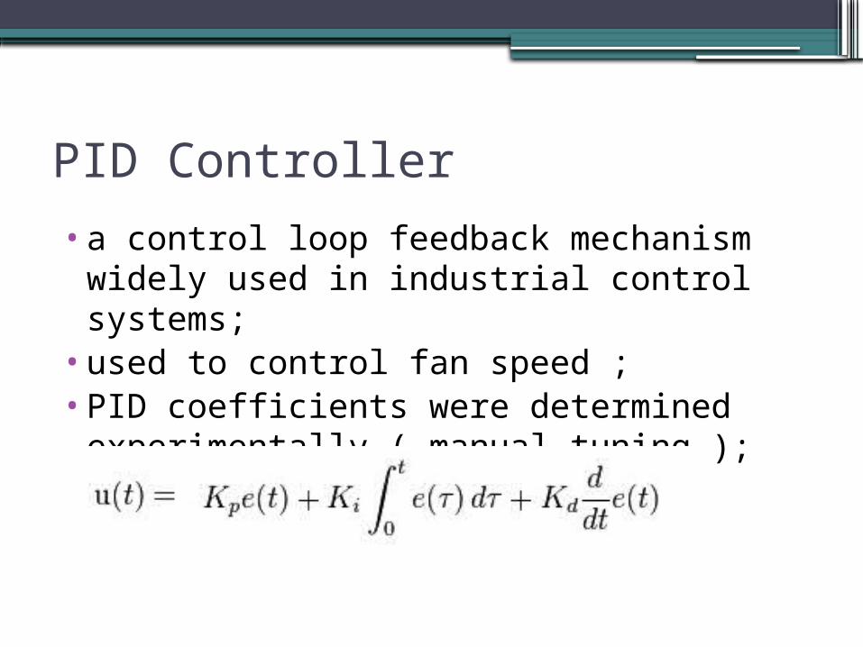
PID Controller
•a control loop feedback mechanism widely used in industrial control systems;
•used to control fan speed ;•PID coefficients were determined
experimentally ( manual tuning );

Wiring scheme

ConclusionsThe following goals have been achieved:• Learning Verilog basics;• Integrate ARM Cortex M0 Design Start IP core and
creating a custom AHB-Lite SoC system with peripherals;• Developing other Verilog specific modules ( for
temperature measuring and display, IR decode, PWM signal generation);
• Developing clear_screen() function for C software;• Creating the cooling/heating algorithms in C;• Handling custom interrupt in Verilog and Assembly;• Developing interactive user interface in C;• Hardware component design and assembling ;• Other improvements ;

Future considerations
•Controlling from distance through an internet connection ( we will use a raspberry pi as a web server, it would be more efficient );
•Extend the design to Intelligent House Project.
Demo

Thank you for your interest!