fp7 high luminosity large hadron collider design study ... · energy deposition simulations for...
TRANSCRIPT
CERN-ACC-2014-0009
HiLumi LHCFP7 High Luminosity Large Hadron Collider Design Study
Deliverable Report
ENERGY DEPOSITION SIMULATIONSFOR UPGRADED COLLIMATION
LAYOUTS
R. Bruce, A. Lechner, S. Redaelli (CERN)
23 January 2014
The HiLumi LHC Design Study is included in the High Luminosity LHC project and ispartly funded by the European Commission within the Framework Programme 7
Capacities Specific Programme, Grant Agreement 284404.
This work is part of HiLumi LHC Work Package 5: Collimation.
The electronic version of this HiLumi LHC Publication is available via the HiLumi LHC web site<http://hilumilhc.web.cern.ch> or on the CERN Document Server at the following URL:
<http://cds.cern.ch/search?p=CERN-ACC-2014-0009>
CERN-ACC-2014-0009
BEAM HALO SIMULATIONS
Doc. Identifier:
Date: 25/11/2013
Grant Agreement No: 284404
HILUMI LHC FP7 High Luminosity Large Hadron Collider Design Study
Seventh Framework Programme, Capac i t ies Spec i f ic Programme, Research In f ras t ructu res, Col laborat i ve Pro ject , Des ign Study
DELIVERABLE REPORT
ENERGY DEPOSITION SIMULATIONS FOR UPGRADED COLLIMATION
LAYOUTS DELIVERABLE: D5.4
Document identifier: HILUMILHC-Del-D5-4_final.docx
Due date of deliverable: End of Month 24 (Oct 2013)
Report release date: 25/11/2013
Work package: WP5
Lead beneficiary: CERN
Document status: Final
Abstract:
Energy deposition simulations: simulate and compare the local energy deposition for both upgraded IR1 and IR5. If more than one qualified scenario exists, comparison of the different scenarios is discussed. This study is important also for generating input to background studies for the experiments.
Grant Agreement 284404 PUBLIC 1 / 28

BEAM HALO SIMULATIONS
Doc. Identifier:
Date: 25/11/2013
Copyright notice: Copyright © HiLumi LHC Consortium, 2014 For more information on HiLumi LHC, its partners and contributors please see www.cern.ch/HiLumiLHC The HiLumi LHC Design Study is included in the High Luminosity LHC project and is partly funded by the European Commission within the Framework Programme 7 Capacities Specific Programme, Grant Agreement 284404. HiLumi LHC began in November 2011 and will run for 4 years. The information herein only reflects the views of its authors and not those of the European Commission and no warranty expressed or implied is made with regard to such information or its use.
Delivery Slip
Name Partner Date
Authored by R. Bruce, A. Lechner, S. Redaelli CERN 20/11/2013
Edited by S. Redaelli, A. Szeberenyi CERN 20/11/2013
Reviewed by R. Appleby [ WP5 deputy coordinator] L. Rossi [Project Coordinator]
CERN 12/12/2013
Approved by Steering Committee 23/01/2014
Grant Agreement 284404 PUBLIC 2 / 28
BEAM HALO SIMULATIONS
Doc. Identifier:
Date: 25/11/2013
TABLE OF CONTENTS
1. Introduction ......................................................................................................................... 4
2. IR7 cleaning without and with DS collimation ................................................................... 6
2.1. layouts studies with different DS collimator configurations ........................................ 6
2.2. Comparative assessment of DS collimation layouts based on energy deposition ...... 10
2.3. Effect of DS Collimators on losses around the ring and impact of machine imperfections ........................................................................................................................ 14
3. Recap. of ion losses in IR2 ................................................................................................ 17
4. energy deposition in IR1/5 with TCL collimators ............................................................. 19
5. Preliminary background calculations for IR1/5 ................................................................ 22
6. FUTURE PLANS / Conclusion / relation to HL-LHC work ............................................ 25
References ................................................................................................................................ 26
Annex: Glossary ....................................................................................................................... 28
Grant Agreement 284404 PUBLIC 3 / 28
BEAM HALO SIMULATIONS
Doc. Identifier:
Date: 25/11/2013
Executive summary The WP5 team has progressed significantly on the layout in all relevant LHC insertions under consideration for collimation upgrades: IR7 for beam halo losses (betatron collimation cleaning), high-luminosity insertions IR1/5 for proton physics debris, IR2 for ion losses. In these cases, the improvement achieved through local dispersion suppressor (DS) collimation was studied in detail. The gain factors in terms of local cleaning of magnet losses were evaluated for the different solutions, in comparison with the standard cleaning without collimator upgrades. The latest energy deposition simulations indicate that the proposed collimator layouts address satisfactorily the challenging collimation upgrade requirements. First background studies were performed for the present (still preliminary) IR1 layout, using as inputs to energy deposition codes the tertiary halo distributions on IR collimators and updated gas distributions. Although these results will have to be repeated when the final layouts as soon as available from WP2, the preliminary conclusions confirm the expected results that the contribution from collimation halo to the experiment background remains small for the HL-LHC era, as it is for the present machine. The results summarized in this report were presented and discussed extensively at the 3rd HiLumi Annual Meeting at Daresbury and at an external collimation project review held at CERN in May 2013. A dedicated WP5 simulation workshop was also organized after the Annual Meeting in order to steer the development of simulation tools within the HiLumi collimation team.
1. INTRODUCTION An external collimation project review was organized in May 2013 [1a] in order to address collimation performance reach and possible upgrade scenarios for implementation during LS2 and LS3. The external review panel re-iterated the strong interest for, and the need to push forward, the development of solutions for the collimation cleaning in the dispersion suppressors (DSs) around cleaning and experimental LHC insertions. The baseline for improving the collimation performance in this way rely on the development of shorter 11 T dipole: 2 of which can replace a standard 15 m long dipole and hence freeing the space for a warm collimator that can serve as a local catcher of dispersive losses. The principle of this concept is robust enough – both for protons and for ions - however detailed simulations were never performed for the complete layout with these collimators and dipoles. These simulations are now completed for the most relevant upgrades cases, i.e. IR7 (betatron cleaning) and IR2 (physics debris losses for Pb-Pb collisions). New layouts are comparatively assessed against the present machine layout. Assessment of different layouts is performed with state-of-the-art simulation tools that include multi-turn tracking for collimation efficiency integrated with energy deposition tools that use a very sophisticated LHC components geometry. These tools were already presented in previous WP5 deliverable documents [REF?] and they have been improved in the last 6
Grant Agreement 284404 PUBLIC 4 / 28
BEAM HALO SIMULATIONS
Doc. Identifier:
Date: 25/11/2013
months, for example by automatizing the preparation of lattice layout with 11 T dipoles replacing the standard dipole cold masses. The latest energy deposition simulations indicate that the proposed collimator layouts address satisfactorily the challenging collimation upgrade requirements. Cleaning of ion debris losses in IR2 can be improved by at least a factor 25 by adding a so-called TCLD collimator in the dispersion suppressor. Similar results are expected in IR1 and IR5 that have not yet been simulated in details (although candidate layout were worked out). The improvement by adding 2 TCLD collimators in IR7 is of about a factor 10 in term of local peak losses in superconducting coils that is relevant for the quench performance. It is important to recall that, whether the losses from ion collision debris in IR2 are above the quench limit of superconducting magnets at 7 TeV, the need of DS collimation in IR7 will have to be addressed during the post-LS1 operation once the quench limits at energies close to 7 TeV are known more precisely. The collimation review panel recommended to continue with high priority quench tests after the LHC start-up in order to address the needs for DS collimation after appropriate operational experience after LS1. In this document, the status of physics debris cleaning in IR1 and IR5 with TCL collimators is also recalled. It is important to note that the present estimates indicate that, for high-luminosity proton operation, there is probably no need for TCLD installations in the DS of IR1 and IR5. This statement must be re-evaluated for the final IR layouts once they will be available. On the other hand, the need for local DS collimation remains in case ATLAS and CMS request to run at the same luminosity as ALICE during heavy ion operation. In this case, similar solutions with 1 TCLD per IP side might be adopted. The first simulations of beam halo and beam gas background in IR1/5 were also performed, the main focus being the understanding of the contribution from collimation halo losses to the experimental background in the high-luminosity experiments. This work is still very preliminary because the layouts of IR1 and IR5 are not yet finalized for the HL-LHC baseline. The same tracking tools established for the cleaning performance study are used for the background simulations: the impact of halo losses on the tertiary collimators close to the experiments are used, together with updated figures for the vacuum pressures, to evaluate the effects of showers into the experiments. The preliminary results indicate that the contribution from collimator losses is moderate for the HL-LHC, as is it for the present machine.
Grant Agreement 284404 PUBLIC 5 / 28
BEAM HALO SIMULATIONS
Doc. Identifier:
Date: 25/11/2013
2. IR7 CLEANING WITHOUT AND WITH DS COLLIMATION In order to assess the effect on the local losses from additional DS collimators, called in the following TCLDs, simulations were performed with both SixTrack [1] and FLUKA [2,3]. SixTrack is a multi-turn element-by-element tracking code that combines a fast and accurate optical tracking through the magnetic lattice with a Monte Carlo simulation (K2) [4] of the proton-matter interaction in the collimators. FLUKA is a fully integrated particle physics Monte Carlo code used to simulate the full shower of the losses and the resulting energy deposition in the superconducting magnets. Section 2.1 gives first an overview of the IR7 layout, followed by the results of the SixTrack simulations. Section 2.2 presents the FLUKA results and in Section 2.3, the effect of imperfections is discussed, as well as losses in other locations around the LHC ring.
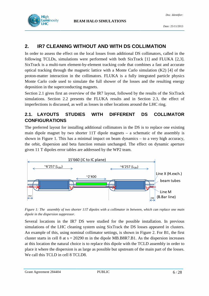
2.1. LAYOUTS STUDIES WITH DIFFERENT DS COLLIMATOR CONFIGURATIONS The preferred layout for installing additional collimators in the DS is to replace one existing main dipole magnet by two shorter 11T dipole magnets – a schematic of the assembly is shown in Figure 1. This has a minimal impact on beam dynamics – to a very high accuracy, the orbit, dispersion and beta function remain unchanged. The effect on dynamic aperture given 11 T dipoles error tables are addressed by the WP2 team.
Figure 1: The assembly of two shorter 11T dipoles with a collimator in between, which can replace one main dipole in the dispersion suppressor.
Several locations in the IR7 DS were studied for the possible installation. In previous simulations of the LHC cleaning system using SixTrack the DS losses appeared in clusters. An example of this, using nominal collimator settings, is shown in Figure 2. For B1, the first cluster starts in cell 8 at s = 20290 m in the dipole MB.B8R7.B1. As the dispersion increases at this location the natural choice is to replace this dipole with the TCLD assembly in order to place it where the dispersion is as large as possible but upstream of the main part of the losses. We call this TCLD in cell 8 TCLD8.
Grant Agreement 284404 PUBLIC 6 / 28
BEAM HALO SIMULATIONS
Doc. Identifier:
Date: 25/11/2013
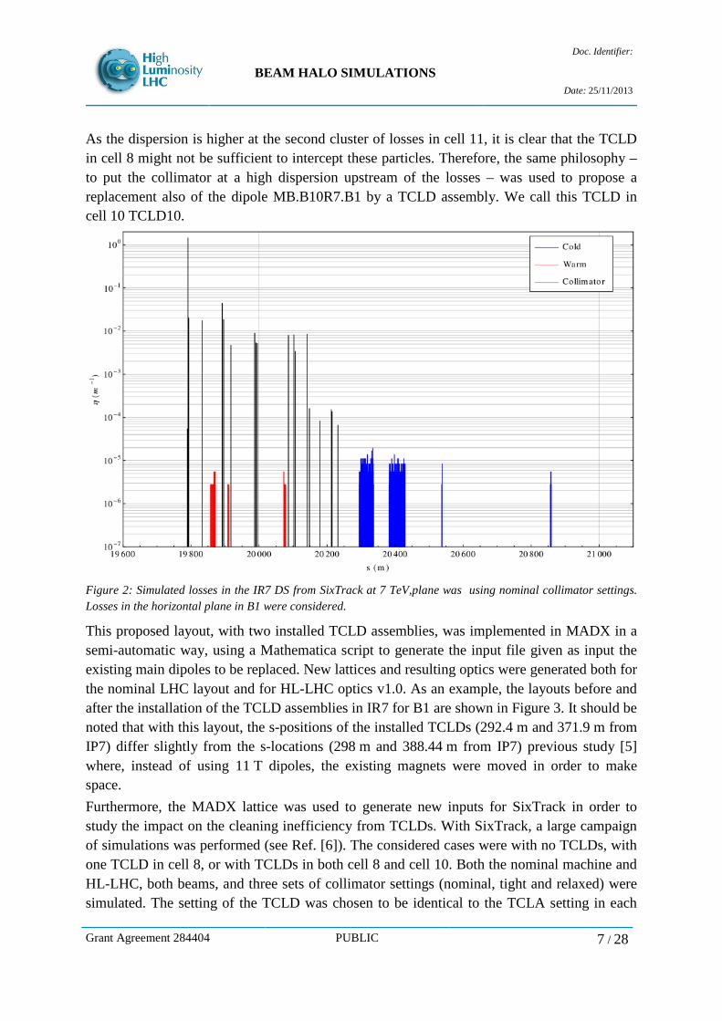
As the dispersion is higher at the second cluster of losses in cell 11, it is clear that the TCLD in cell 8 might not be sufficient to intercept these particles. Therefore, the same philosophy – to put the collimator at a high dispersion upstream of the losses – was used to propose a replacement also of the dipole MB.B10R7.B1 by a TCLD assembly. We call this TCLD in cell 10 TCLD10.
Figure 2: Simulated losses in the IR7 DS from SixTrack at 7 TeV,plane was using nominal collimator settings. Losses in the horizontal plane in B1 were considered.
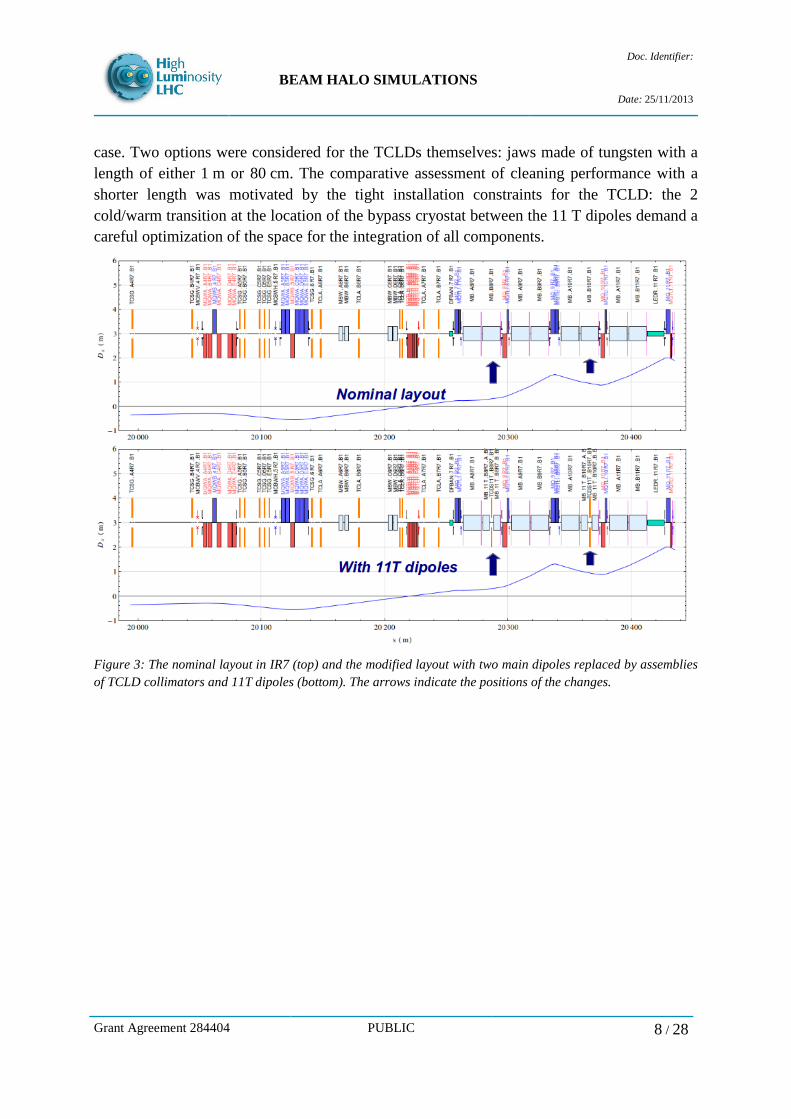
This proposed layout, with two installed TCLD assemblies, was implemented in MADX in a semi-automatic way, using a Mathematica script to generate the input file given as input the existing main dipoles to be replaced. New lattices and resulting optics were generated both for the nominal LHC layout and for HL-LHC optics v1.0. As an example, the layouts before and after the installation of the TCLD assemblies in IR7 for B1 are shown in Figure 3. It should be noted that with this layout, the s-positions of the installed TCLDs (292.4 m and 371.9 m from IP7) differ slightly from the s-locations (298 m and 388.44 m from IP7) previous study [5] where, instead of using 11 T dipoles, the existing magnets were moved in order to make space. Furthermore, the MADX lattice was used to generate new inputs for SixTrack in order to study the impact on the cleaning inefficiency from TCLDs. With SixTrack, a large campaign of simulations was performed (see Ref. [6]). The considered cases were with no TCLDs, with one TCLD in cell 8, or with TCLDs in both cell 8 and cell 10. Both the nominal machine and HL-LHC, both beams, and three sets of collimator settings (nominal, tight and relaxed) were simulated. The setting of the TCLD was chosen to be identical to the TCLA setting in each
Grant Agreement 284404 PUBLIC 7 / 28
BEAM HALO SIMULATIONS
Doc. Identifier:
Date: 25/11/2013
case. Two options were considered for the TCLDs themselves: jaws made of tungsten with a length of either 1 m or 80 cm. The comparative assessment of cleaning performance with a shorter length was motivated by the tight installation constraints for the TCLD: the 2 cold/warm transition at the location of the bypass cryostat between the 11 T dipoles demand a careful optimization of the space for the integration of all components.
Figure 3: The nominal layout in IR7 (top) and the modified layout with two main dipoles replaced by assemblies of TCLD collimators and 11T dipoles (bottom). The arrows indicate the positions of the changes.
Grant Agreement 284404 PUBLIC 8 / 28
BEAM HALO SIMULATIONS
Doc. Identifier:
Date: 25/11/2013
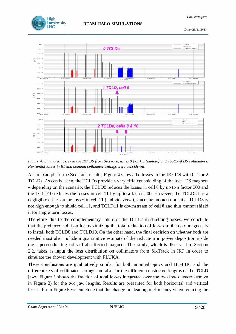
Figure 4: Simulated losses in the IR7 DS from SixTrack, using 0 (top), 1 (middle) or 2 (bottom) DS collimators. Horizontal losses in B1 and nominal collimator settings were considered.
As an example of the SixTrack results, Figure 4 shows the losses in the IR7 DS with 0, 1 or 2 TCLDs. As can be seen, the TCLDs provide a very efficient shielding of the local DS magnets – depending on the scenario, the TCLD8 reduces the losses in cell 8 by up to a factor 300 and the TCLD10 reduces the losses in cell 11 by up to a factor 500. However, the TCLD8 has a negligible effect on the losses in cell 11 (and viceversa), since the momentum cut at TCLD8 is not high enough to shield cell 11, and TCLD11 is downstream of cell 8 and thus cannot shield it for single-turn losses. Therefore, due to the complementary nature of the TCLDs in shielding losses, we conclude that the preferred solution for maximizing the total reduction of losses in the cold magnets is to install both TCLD8 and TCLD10. On the other hand, the final decision on whether both are needed must also include a quantitative estimate of the reduction in power deposition inside the superconducting coils of all affected magnets. This study, which is discussed in Section 2.2, takes as input the loss distribution on collimators from SixTrack in IR7 in order to simulate the shower development with FLUKA. These conclusions are qualitatively similar for both nominal optics and HL-LHC and the different sets of collimator settings and also for the different considered lengths of the TCLD jaws. Figure 5 shows the fraction of total losses integrated over the two loss clusters (shown in Figure 2) for the two jaw lengths. Results are presented for both horizontal and vertical losses. From Figure 5 we conclude that the change in cleaning inefficiency when reducing the
Grant Agreement 284404 PUBLIC 9 / 28

BEAM HALO SIMULATIONS
Doc. Identifier:
Date: 25/11/2013
length of the jaw from 1 m to 80 cm is negligible. Since the 80 cm design provides several advantages from the integration point of view, we conclude that this is the preferred option.
Figure 5: Fraction of losses in the two clusters in the IR7 DS (see Figure 2) for different lengths of the TCLD jaws (1m or 80cm), horizontal or vertical losses. Horizontal losses in B2 were considered.
2.2. COMPARATIVE ASSESSMENT OF DS COLLIMATION LAYOUTS BASED ON ENERGY DEPOSITION Detailed power deposition calculations (see Refs. [7,8]) were performed with FLUKA in order to estimate the risk of magnet quenches and to quantify the achievable reduction factor due to the TCLDs. Loss rates are evaluated for the reference case of low beam lifetime (0.2 h during 10 s). In this section, results for nominal 7 TeV operation are reported, which compare the existing layout with the layout accommodating both TCLDs. FLUKA simulations were based on a realistic IR7 model featuring geometrical characteristics essential for energy deposition studies, including an accurate representation of magnets and collimators. As a first simulation step, products of inelastic nuclear interactions, including single diffractive protons, were generated in LSS collimators in FLUKA according to the spatial distribution of collisions predicted by SixTrack. Secondly, high-energy particles emerging from these collisions or from consecutive showers were transported throughout the LSS, eventually followed by detailed simulations of the energy deposition in DS magnets. In all simulations, losses were assumed to be horizontal only (i.e., primary beam losses on the horizontal primary collimator) that is known to be the worst case for collimation cleaning.
Grant Agreement 284404 PUBLIC 10 / 28
BEAM HALO SIMULATIONS
Doc. Identifier:
Date: 25/11/2013
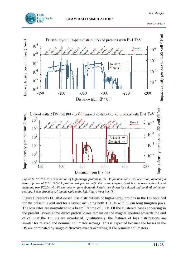
Figure 6: FLUKA loss distribution of high-energy protons in the DS for nominal 7 TeV operation, assuming a beam lifetime of 0.2 h (4.5e11 protons lost per second). The present layout (top) is compared with a layout including two TCLDs with 80 cm tungsten jaws (bottom). Results are shown for relaxed and nominal collimator settings. Beam direction is from the right to the left. Figure from Ref. [8].
Figure 6 presents FLUKA-based loss distributions of high-energy protons in the DS obtained for the present layout and for a layout including both TCLDs with 80 cm long tungsten jaws. The loss rates are normalized to a beam lifetime of 0.2 h. Of the clustered losses appearing in the present layout, some direct proton losses remain on the magnet aperture towards the end of cell 9 if the TCLDs are introduced. Qualitatively, the features of loss distributions are similar for relaxed and nominal collimator settings. This is expected because the losses in the DS are dominated by single-diffractive events occurring at the primary collimators.
Grant Agreement 284404 PUBLIC 11 / 28
BEAM HALO SIMULATIONS
Doc. Identifier:
Date: 25/11/2013
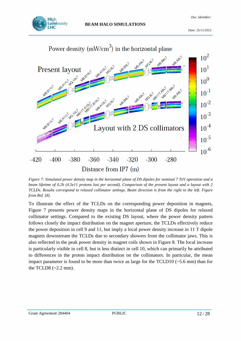
Figure 7: Simulated power density map in the horizontal plane of DS dipoles for nominal 7 TeV operation and a beam lifetime of 0.2h (4.5e11 protons lost per second). Comparison of the present layout and a layout with 2 TCLDs. Results correspond to relaxed collimator settings. Beam direction is from the right to the left. Figure from Ref. [8].
To illustrate the effect of the TCLDs on the corresponding power deposition in magnets, Figure 7 presents power density maps in the horizontal plane of DS dipoles for relaxed collimator settings. Compared to the existing DS layout, where the power density pattern follows closely the impact distribution on the magnet aperture, the TCLDs effectively reduce the power deposition in cell 9 and 11, but imply a local power density increase in 11 T dipole magnets downstream the TCLDs due to secondary showers from the collimator jaws. This is also reflected in the peak power density in magnet coils shown in Figure 8. The local increase is particularly visible in cell 8, but is less distinct in cell 10, which can primarily be attributed to differences in the proton impact distribution on the collimators. In particular, the mean impact parameter is found to be more than twice as large for the TCLD10 (~5.6 mm) than for the TCLD8 (~2.2 mm).
Grant Agreement 284404 PUBLIC 12 / 28

BEAM HALO SIMULATIONS
Doc. Identifier:
Date: 25/11/2013
Figure 8: Peak power densities in coils of DS magnets for nominal 7 TeV operation, assuming a beam lifetime of 0.2 h (4.5e11 protons lost per second). Comparison of the present layout and a layout with 2 TCLDs. Results correspond to relaxed collimator settings. Beam direction is from the right to the left. Figure from Ref. [8].
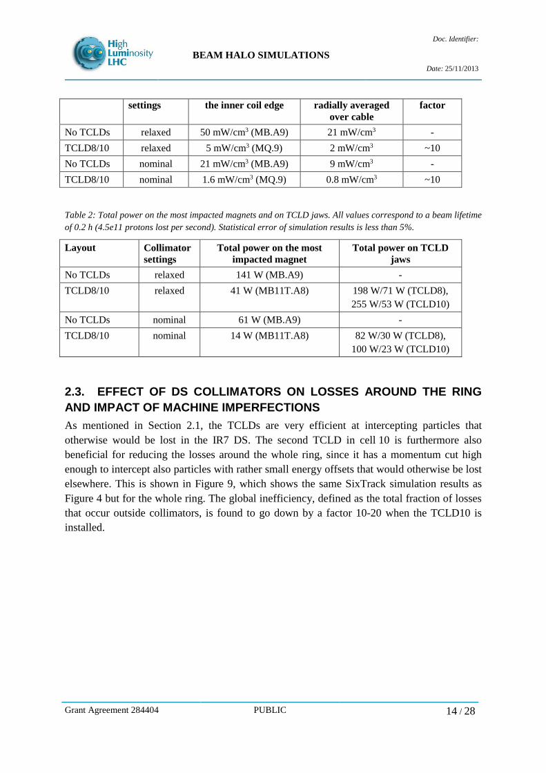
In the present DS layout, the highest peak power density in magnet coils occurs in the front of MB.A9, while in the layout with two TCLDs the limiting location appears to be towards the end of cell 9 (MQ.9) due to the remaining proton losses on the magnet beam screen. The simulation results suggest that with two TCLDs an overall reduction by about a factor 10 can be achieved. This reduction factor holds for both collimator settings considered in the simulations (relaxed and nominal). Tables 1 and 2 summarize the obtained maximum peak power densities in magnet coils for both collimator settings, as well as the total power deposited in TCLD jaws and in the most impacted magnets. Recent estimates of the steady-state quench limit of MB cables at 7 TeV range from 25 mW/cm3 [9] to 47 mW/cm3 [10]. For the existing layout this is to be compared to a (radially averaged) power density of ~9 mW/cm3 for nominal settings and ~21 mW/cm3 for relaxed settings. With TCLDs, peak power densities are found to be about one order of magnitude less than the estimated quench limits of MB and MQ (53 mW/cm3 [10]) even for relaxed collimator settings.
Table 1: Peak power densities at the inner coil edge, as well as peak power densities radially averaged over the cable, for relaxed and nominal collimator settings. All values correspond to a beam lifetime of 0.2 h (4.5e11 protons lost per second). Statistical error of simulation results is less than 12%.
Layout Collimator Peak power density at Peak power density Reduction
Grant Agreement 284404 PUBLIC 13 / 28
BEAM HALO SIMULATIONS
Doc. Identifier:
Date: 25/11/2013
settings the inner coil edge radially averaged
over cable factor
No TCLDs relaxed 50 mW/cm3 (MB.A9) 21 mW/cm3 - TCLD8/10 relaxed 5 mW/cm3 (MQ.9) 2 mW/cm3 ~10 No TCLDs nominal 21 mW/cm3 (MB.A9) 9 mW/cm3 - TCLD8/10 nominal 1.6 mW/cm3 (MQ.9) 0.8 mW/cm3 ~10
Table 2: Total power on the most impacted magnets and on TCLD jaws. All values correspond to a beam lifetime of 0.2 h (4.5e11 protons lost per second). Statistical error of simulation results is less than 5%.
Layout Collimator settings
Total power on the most impacted magnet
Total power on TCLD jaws
No TCLDs relaxed 141 W (MB.A9) - TCLD8/10 relaxed 41 W (MB11T.A8) 198 W/71 W (TCLD8),
255 W/53 W (TCLD10) No TCLDs nominal 61 W (MB.A9) - TCLD8/10 nominal 14 W (MB11T.A8) 82 W/30 W (TCLD8),
100 W/23 W (TCLD10)
2.3. EFFECT OF DS COLLIMATORS ON LOSSES AROUND THE RING AND IMPACT OF MACHINE IMPERFECTIONS As mentioned in Section 2.1, the TCLDs are very efficient at intercepting particles that otherwise would be lost in the IR7 DS. The second TCLD in cell 10 is furthermore also beneficial for reducing the losses around the whole ring, since it has a momentum cut high enough to intercept also particles with rather small energy offsets that would otherwise be lost elsewhere. This is shown in Figure 9, which shows the same SixTrack simulation results as Figure 4 but for the whole ring. The global inefficiency, defined as the total fraction of losses that occur outside collimators, is found to go down by a factor 10-20 when the TCLD10 is installed.
Grant Agreement 284404 PUBLIC 14 / 28
BEAM HALO SIMULATIONS
Doc. Identifier:
Date: 25/11/2013
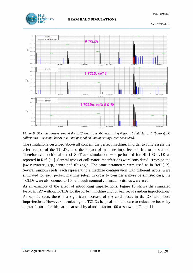
Figure 9: Simulated losses around the LHC ring from SixTrack, using 0 (top), 1 (middle) or 2 (bottom) DS collimators. Horizontal losses in B1 and nominal collimator settings were considered.
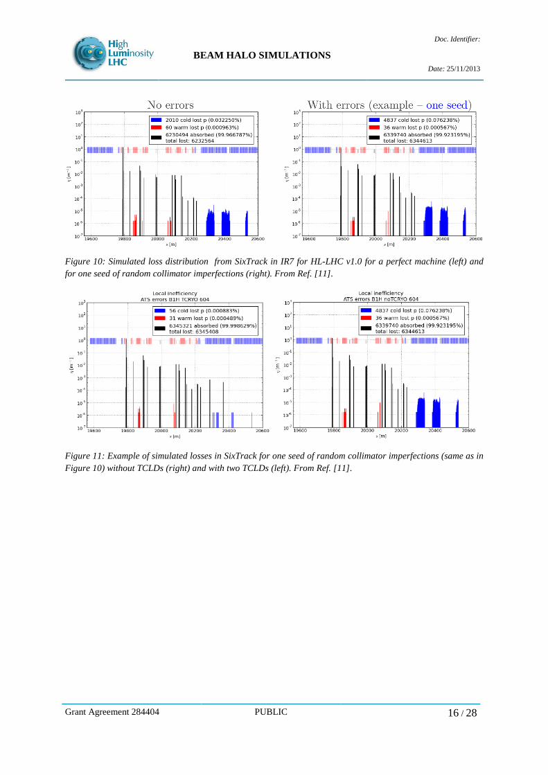
The simulations described above all concern the perfect machine. In order to fully assess the effectiveness of the TCLDs, also the impact of machine imperfections has to be studied. Therefore an additional set of SixTrack simulations was performed for HL-LHC v1.0 as reported in Ref. [11]. Several types of collimator imperfections were considered: errors on the jaw curvature, gap, centre and tilt angle. The same parameters were used as in Ref. [12]. Several random seeds, each representing a machine configuration with different errors, were simulated for each perfect machine setup. In order to consider a more pessimistic case, the TCLDs were also opened to 15σ although nominal collimator settings were used. As an example of the effect of introducing imperfections, Figure 10 shows the simulated losses in IR7 without TCLDs for the perfect machine and for one set of random imperfections. As can be seen, there is a significant increase of the cold losses in the DS with these imperfections. However, introducing the TCLDs helps also in this case to reduce the losses by a great factor – for this particular seed by almost a factor 100 as shown in Figure 11.
Grant Agreement 284404 PUBLIC 15 / 28
BEAM HALO SIMULATIONS
Doc. Identifier:
Date: 25/11/2013
Figure 10: Simulated loss distribution from SixTrack in IR7 for HL-LHC v1.0 for a perfect machine (left) and for one seed of random collimator imperfections (right). From Ref. [11].
Figure 11: Example of simulated losses in SixTrack for one seed of random collimator imperfections (same as in Figure 10) without TCLDs (right) and with two TCLDs (left). From Ref. [11].
Grant Agreement 284404 PUBLIC 16 / 28
BEAM HALO SIMULATIONS
Doc. Identifier:
Date: 25/11/2013
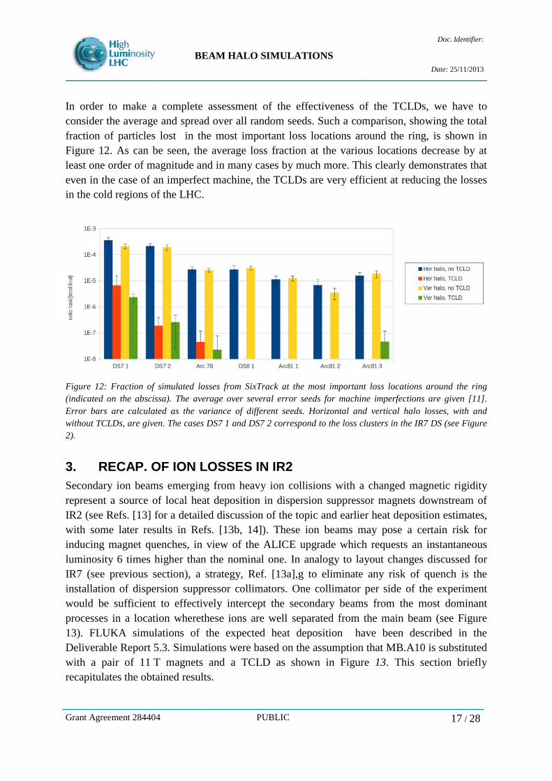
In order to make a complete assessment of the effectiveness of the TCLDs, we have to consider the average and spread over all random seeds. Such a comparison, showing the total fraction of particles lost in the most important loss locations around the ring, is shown in Figure 12. As can be seen, the average loss fraction at the various locations decrease by at least one order of magnitude and in many cases by much more. This clearly demonstrates that even in the case of an imperfect machine, the TCLDs are very efficient at reducing the losses in the cold regions of the LHC.
Figure 12: Fraction of simulated losses from SixTrack at the most important loss locations around the ring (indicated on the abscissa). The average over several error seeds for machine imperfections are given [11]. Error bars are calculated as the variance of different seeds. Horizontal and vertical halo losses, with and without TCLDs, are given. The cases DS7 1 and DS7 2 correspond to the loss clusters in the IR7 DS (see Figure 2).
3. RECAP. OF ION LOSSES IN IR2 Secondary ion beams emerging from heavy ion collisions with a changed magnetic rigidity represent a source of local heat deposition in dispersion suppressor magnets downstream of IR2 (see Refs. [13] for a detailed discussion of the topic and earlier heat deposition estimates, with some later results in Refs. [13b, 14]). These ion beams may pose a certain risk for inducing magnet quenches, in view of the ALICE upgrade which requests an instantaneous luminosity 6 times higher than the nominal one. In analogy to layout changes discussed for IR7 (see previous section), a strategy, Ref. [13a],g to eliminate any risk of quench is the installation of dispersion suppressor collimators. One collimator per side of the experiment would be sufficient to effectively intercept the secondary beams from the most dominant processes in a location wherethese ions are well separated from the main beam (see Figure 13). FLUKA simulations of the expected heat deposition have been described in the Deliverable Report 5.3. Simulations were based on the assumption that MB.A10 is substituted with a pair of 11 T magnets and a TCLD as shown in Figure 13. This section briefly recapitulates the obtained results.
Grant Agreement 284404 PUBLIC 17 / 28

BEAM HALO SIMULATIONS
Doc. Identifier:
Date: 25/11/2013
Figure 13:Secondary beam, shown in the horizontal plane, emerging from IP2 and potentially quenching dispersion suppressor magnets. A collimator installed in the position indicated can intercept the most intense (red) beam as discussed in Reference 13. For an ALICE luminosity of 6x1027cm-2s-1, FLUKA simulations predict a peak power density of ~48 mW/cm3 (radial average) in MB.B10 coils if the DS layout remains as it is now. This is about a factor 2 above the estimated quench limit in Ref. [9] and about the same as the quench limit in Ref. [10]. . Depending on the jaw material, jaw length and half gap, a TCLD would reduce the peak power density to a few mW/cm3 or less in the 11 T dipole magnet downstream of the TCLD (seeing Table 3). The total power deposited in jaws is found to be comparable or larger than the power deposition in the downstream magnet (see Table 4). Although the steady-state quench limit of the 11T dipole is still subject of investigation, the obtained peak power densities in coils (with the DS collimator installed) are assumed to be safely below and eventually allow for a broad margin even for the requested ALICE luminosity upgrade. All mentioned estimates of heat deposition only include the contribution due to Pb81+ ions from bound-free pair production (BFPP1), which represents the process with the largest cross section. However, a TCLD at the s-position assumed in this study would also be able to intercept other secondary beams.
Table 3: Calculated peak energy density in magnet coils for different layouts with and without a TCLD collimator. Values only include the contribution due to BFPP1, assuming an ALICE peak luminosity of 6x1027cm-2s-1. Table as presented by G. Steele et al. [14] at the LHC Collimation Review 2013.
Layout Length / Peak power density at Peak power density Reduction Grant Agreement 284404 PUBLIC 18 / 28

BEAM HALO SIMULATIONS
Doc. Identifier:
Date: 25/11/2013
material /
setting the inner coil edge radially averaged over
cable factor
No TCLDs - 93 mW/cm3 (MB.B10) 44 mW/cm3 (MB.B10) -
With TCLD 0.5 m / Cu / 43 σ
3.7 mW/cm3
(MB11T.A10) 3.1 mW/cm3
(MB11T.A10) ~25
With TCLD 1 m / W / 43σ
0.8 mW/cm3
(MB11T.A10) 0.7 mW/cm3
(MB11T.A10) >100
With TCLD 1 m / W/ 9σ
<0.1 mW/cm3
(MB11T.A10) <0.1 mW/cm3 (MB11T.A10)
>900
Table 4: Total power on most impacted magnets and TCLD jaws. Values only include the contribution due to BFPP1, assuming an ALICE peak luminosity of 6x1027cm-2s-1. Table as presented by G. Steele et al. [14] at the LHC Collimation Review 2013.
Layout Length / material / setting
Total power on most impacted magnet
Total power on TCLD jaws
No TCLDs - 95 W (MB.B10) - With TCLD 0.5 m / Cu / 43 σ 46 W (MB11T.A10) 42 W/6.5 W With TCLD 1 m / W / 43 σ 8 W (MB11T.A10) 77 W/13 W With TCLD 1 m / W / 9 σ 3 W (MB11T.A10) 96 W/6.5W
4. ENERGY DEPOSITION IN IR1/5 WITH TCL COLLIMATORS As a protection measure against proton collision debris from the IPs, the pre-LS1 IR1/5 layouts included one TCL, installed in front of Q5 (TCL-5), which will be complemented by an additional TCL in front of D2/Q4 (TCL-4) during LS1 [15]. Both TCL-4 and TCL-5 are part of the nominal collimation layout for the 7 TeV operation. In addition, the installation of a third TCL in front of Q6 (TCL-6) is being considered [15]. As discussed in the Deliverable Reports 5.2 and 5.3, no further installations of physics debris collimators are currently planned until LS3. In combination with masks upstream of magnets [16], the proposed TCL protection configuration could potentially pose a valid option also for HL-LHC operation beyond LS3. Clearly, the TCL positions will have to be updated to follow the updated magnet positions in the new IR layouts. As a first step towards the new TCL layout, FLUKA simulations have been carried out to quantify the TCL protection efficiency for nominal operation after LS1. First results have been presented in the Deliverable Report 5.3 (taken from Ref. [17]), demonstrating the impact of TCL-4 and TCL-5 on the machine when being operated with a half gap of 10σ. In this report, results from new simulation studies (from Ref. [18]) are shown, which investigate the protection efficiency of the TCL-6, as well as the consequences of more relaxed TCL settings, as potentially required by forward physics experiments. The increase of radiation levels in RRs due to secondary showers from the TCL-6 and the corresponding impact on electronics installed in these RRs are subject of ongoing investigations.
Grant Agreement 284404 PUBLIC 19 / 28
BEAM HALO SIMULATIONS
Doc. Identifier:
Date: 25/11/2013
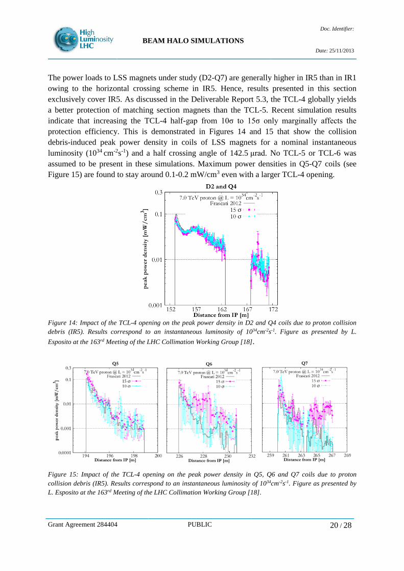
The power loads to LSS magnets under study (D2-Q7) are generally higher in IR5 than in IR1 owing to the horizontal crossing scheme in IR5. Hence, results presented in this section exclusively cover IR5. As discussed in the Deliverable Report 5.3, the TCL-4 globally yields a better protection of matching section magnets than the TCL-5. Recent simulation results indicate that increasing the TCL-4 half-gap from 10σ to 15σ only marginally affects the protection efficiency. This is demonstrated in Figures 14 and 15 that show the collision debris-induced peak power density in coils of LSS magnets for a nominal instantaneous luminosity (1034 cm-2s-1) and a half crossing angle of 142.5 μrad. No TCL-5 or TCL-6 was assumed to be present in these simulations. Maximum power densities in Q5-Q7 coils (see Figure 15) are found to stay around 0.1-0.2 mW/cm3 even with a larger TCL-4 opening.
Figure 14: Impact of the TCL-4 opening on the peak power density in D2 and Q4 coils due to proton collision debris (IR5). Results correspond to an instantaneous luminosity of 1034cm-2s-1. Figure as presented by L. Esposito at the 163rd Meeting of the LHC Collimation Working Group [18].
Figure 15: Impact of the TCL-4 opening on the peak power density in Q5, Q6 and Q7 coils due to proton collision debris (IR5). Results correspond to an instantaneous luminosity of 1034cm-2s-1. Figure as presented by L. Esposito at the 163rd Meeting of the LHC Collimation Working Group [18].
Grant Agreement 284404 PUBLIC 20 / 28

BEAM HALO SIMULATIONS
Doc. Identifier:
Date: 25/11/2013
Several configurations where studied to evaluate the efficiency of TCL-6 in reducing the energy deposition in Q6 and Q7 induced by secondary showers from Roman Pots. As shown in Figure 16, the peak power density in magnet coils increases by up to a factor 10 if Roman Pots are inserted and if no TCL-6 is present. These simulations were based on the assumption that TCL-4 and TCL-5 are open at 15 σ and 35 σ, and that either Roman Pots 1 and 2 or Roman Pot 4 are inserted at 11 σ. Figure 17 illustrates that adding TCL-6 (tungsten jaws, 10 σ half-gap) allows to reduce the peak power density by approximately a factor 2-3. In any case, for an instantaneous luminosity of 1034 cm-2s-1 the peak power density in Q6 and Q7 coils is predicted to stay well below 1 mW/cm3 even without TCL-6.
Figure 16: Peak power density in Q6 and Q7 coils for different operating conditions of TOTEM Roman Pots. Results correspond to an instantaneous luminosity of 1034cm-2s-1. Figure as presented by L. Esposito at the 163rd Meeting of the LHC Collimation Working Group [18].
Figure 17: Peak power density in Q6 and Q7 coils with and without TCL-6. Results correspond to an instantaneous luminosity of 1034cm-2s-1. Figure as presented by L. Esposito at the 163rd Meeting of the LHC Collimation Working Group [18].
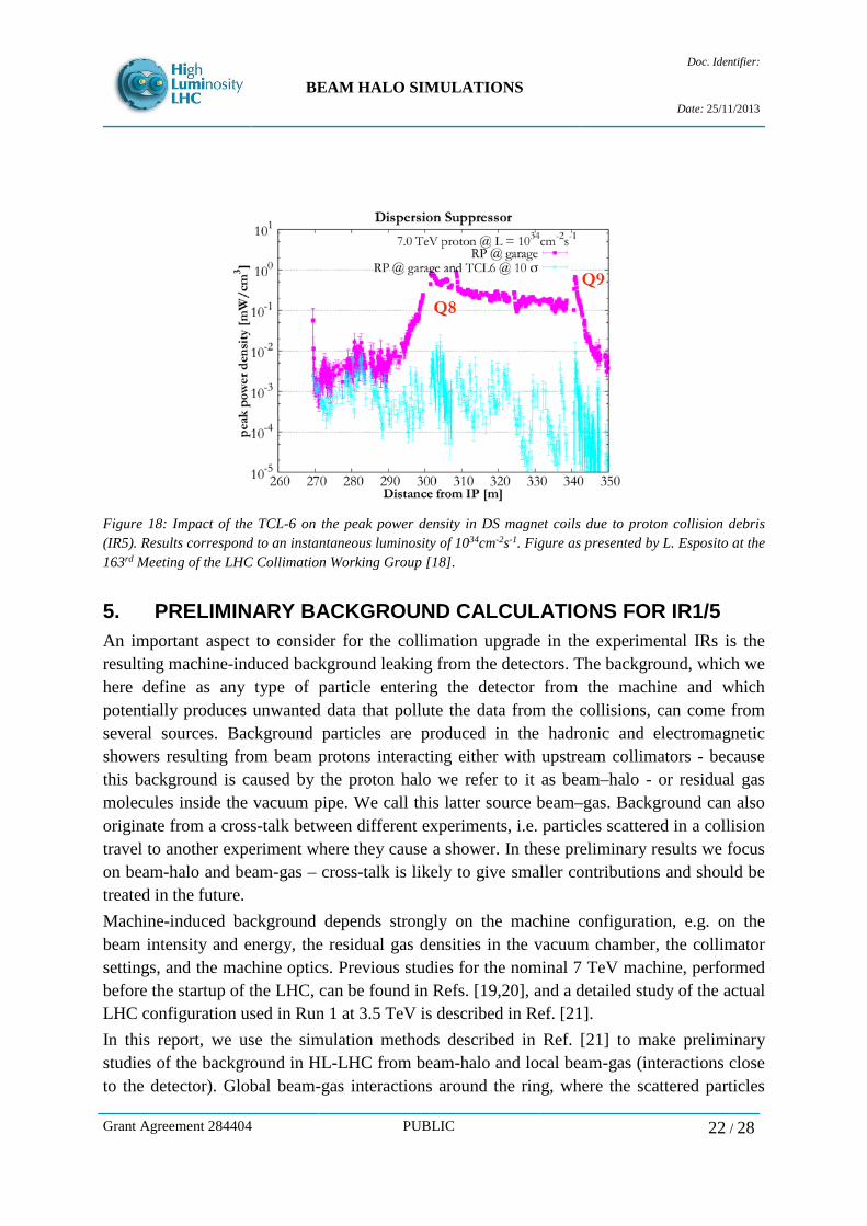
Independently of Roman Pot operation, the TCL-6 is found to substantially reduce the power deposition in the dispersion suppressor magnets up to the Q9. This is illustrated in Figure 18, which shows the peak power density in DS magnet coils with and without TCL-6.
Grant Agreement 284404 PUBLIC 21 / 28
BEAM HALO SIMULATIONS
Doc. Identifier:
Date: 25/11/2013
Figure 18: Impact of the TCL-6 on the peak power density in DS magnet coils due to proton collision debris (IR5). Results correspond to an instantaneous luminosity of 1034cm-2s-1. Figure as presented by L. Esposito at the 163rd Meeting of the LHC Collimation Working Group [18].
5. PRELIMINARY BACKGROUND CALCULATIONS FOR IR1/5 An important aspect to consider for the collimation upgrade in the experimental IRs is the resulting machine-induced background leaking from the detectors. The background, which we here define as any type of particle entering the detector from the machine and which potentially produces unwanted data that pollute the data from the collisions, can come from several sources. Background particles are produced in the hadronic and electromagnetic showers resulting from beam protons interacting either with upstream collimators - because this background is caused by the proton halo we refer to it as beam–halo - or residual gas molecules inside the vacuum pipe. We call this latter source beam–gas. Background can also originate from a cross-talk between different experiments, i.e. particles scattered in a collision travel to another experiment where they cause a shower. In these preliminary results we focus on beam-halo and beam-gas – cross-talk is likely to give smaller contributions and should be treated in the future. Machine-induced background depends strongly on the machine configuration, e.g. on the beam intensity and energy, the residual gas densities in the vacuum chamber, the collimator settings, and the machine optics. Previous studies for the nominal 7 TeV machine, performed before the startup of the LHC, can be found in Refs. [19,20], and a detailed study of the actual LHC configuration used in Run 1 at 3.5 TeV is described in Ref. [21]. In this report, we use the simulation methods described in Ref. [21] to make preliminary studies of the background in HL-LHC from beam-halo and local beam-gas (interactions close to the detector). Global beam-gas interactions around the ring, where the scattered particles
Grant Agreement 284404 PUBLIC 22 / 28
BEAM HALO SIMULATIONS
Doc. Identifier:
Date: 25/11/2013
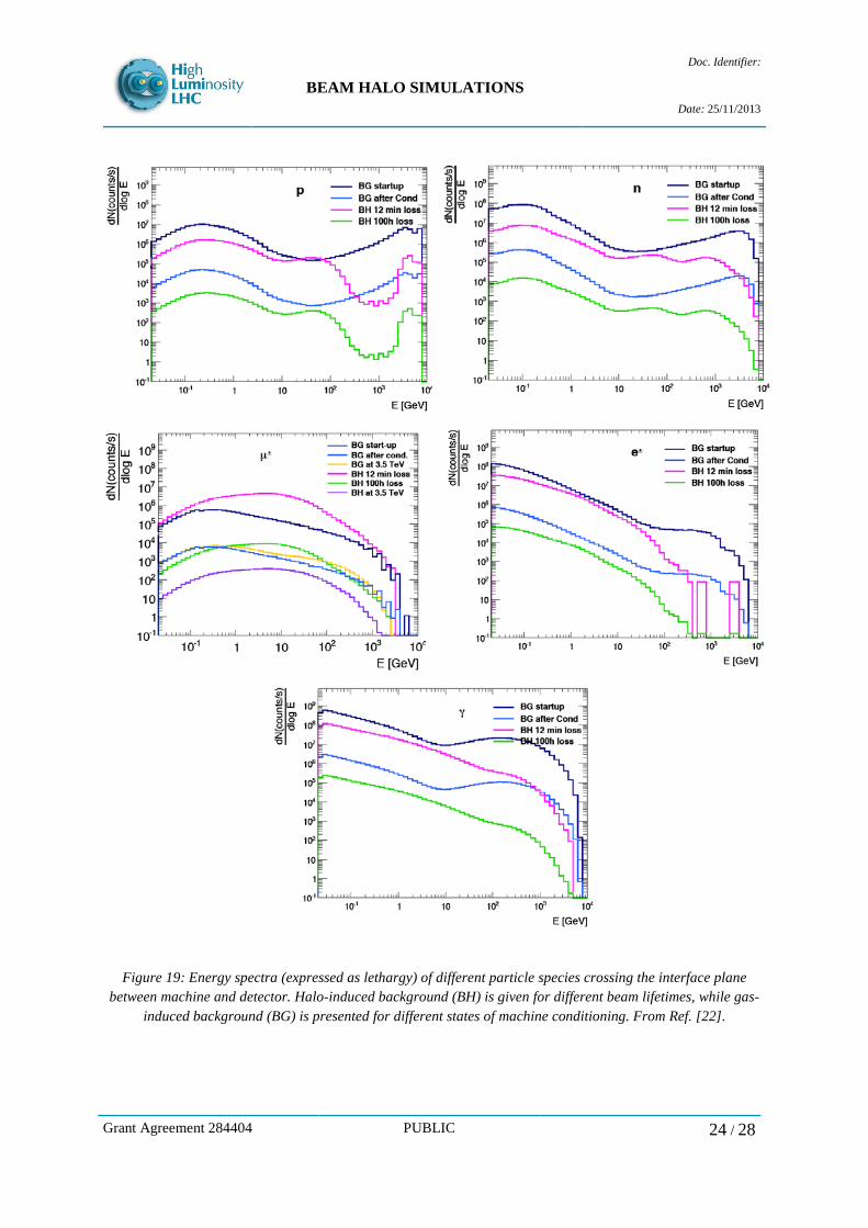
travel over longer distances to the experimental insertions, have not yet been studied as there are presently too many unknowns, in particular the residual pressure profile around the ring. As a starting point, we consider here IR1 and the round 15 cm optics HL-LHC v1.0. It is clear that also these results are preliminary, as the inputs (e.g. the layout) are not frozen yet, and that the simulations would have to be repeated in the future if there are changes. Note in particular that it is foreseen to add additional tertiary collimators in from of Q4 and Q5 as opposed to the present layout where only the triplet magnet is protected. These simulations assume collimator locations at the triplet only as a worst case scenarios (background source closest to the experiment). The simulation method used for beam-halo is a SixTrack simulation of the cleaning system, as described in Section 2.1, where the locations of the inelastic interactions in the TCTs are recorded. These positions serve as starting conditions for a second step, where FLUKA is used to simulate the shower from the TCT to the detector. The simulation output is the particle distribution at an interface plane between the machine and detector, which is defined to be at 22.6 m from the IP. For local beam-gas, we perform only one simulation step, consisting of a FLUKA simulation of the local shower directly from beam-gas events close to the detector. Figure 19 presents calculated energy spectra for different types of particles traversing the interface plane. Spectra corresponding to beam halo-induced background are presented for beam lifetimes of 12 minutes and 100 hours, respectively. On the other hand, the background due to gas-induced beam losses is described for machine start-up conditions as well as for a fully conditioned machine; in either case, estimates of the gas pressure were based on conservative assumptions taking into account uncertainties in layout, effective dimensions and pumping speed. Contributions from both synchrotron radiation and electron cloud build-up were included in the considered gas pressure profiles. Simulation results show that the highest particle rates can be expected due to beam-gas interactions under start-up conditions, except for muons, where the halo-induced contribution can be dominating if one encounters a period of short beam lifetime. Assuming a fully conditioned machine, the obtained muon rates due to beam-gas interactions are comparable to the rates derived for the 3.5 TeV operation. On the contrary, the halo-induced muon background is estimated to be about 10 times higher than at 3.5 TeV. The output files, in terms of particle distributions entering the experimental detectors can be used as starting conditions for a dedicated simulation of the detectors by the experiments. The files are available for the experiments upon request from the authors.
Grant Agreement 284404 PUBLIC 23 / 28
BEAM HALO SIMULATIONS
Doc. Identifier:
Date: 25/11/2013
Figure 19: Energy spectra (expressed as lethargy) of different particle species crossing the interface plane between machine and detector. Halo-induced background (BH) is given for different beam lifetimes, while gas-
induced background (BG) is presented for different states of machine conditioning. From Ref. [22].
Grant Agreement 284404 PUBLIC 24 / 28
BEAM HALO SIMULATIONS
Doc. Identifier:
Date: 25/11/2013
6. FUTURE PLANS / CONCLUSION / RELATION TO HL-LHC WORK The progress of the WP5 activities in the last year has been outstanding. The analysis of the operational data (including in particular a collimation quench test) was performed for a collimation review that took place in May 2013. This was used to come up with a baseline upgrade strategy that for the moment has put the focus on the upgrade of the dispersion suppressors in IR7 (protons) and IR2 (ions), for possible implementation in LS2. It seems clear that the LHC operation in the HL-LHC era would greatly profit if this technology was adopted also in IR1/5 (ions). This deliverable document reported also about recent studied of background in IR1 from collimation halo and beam gas interaction, done for the first time for the HL-LHC baseline optics. These results will have to be updated for the final layout of IR1 and IR5. This will be done for the frozen version of the matching sections in these points. In particular, the cases with additional tertiary collimators further away from the IP (cells 4 or 5) must be considered. The effectiveness of the TCL collimators for physics debris cleaning with high-luminosity proton runs will also have to be addressed for the final layouts. Preliminary results indicate that 3 TCLs in cells 4, 5 and 6 at either side of the IP might do the job and clean adequately also the losses in the DSs. Concerning the studies in IR7, more comparative cases are being addressed, for example to study with energy deposition tools if 1 TCLD in cell 8 might be already sufficient to improve partially the cleaning. The option of having one collimator and 2 11 T dipoles per side only might be interesting as a “staged approach” to the problem, in case fewer 11 T dipole units than needed would be available in LS2. The results now available in terms of energy deposition in the 11 T dipole coils have been provided to the magnet team to address the quench performance for the new loss scenarios. WP5 works on that in strong collaboration with WP11 in addition to the long-lasting collaboration with WP10. Depending on the results of this analysis and comparisons with updated quench tests, a re-iteration on IR7 layouts might be required.
Grant Agreement 284404 PUBLIC 25 / 28
BEAM HALO SIMULATIONS
Doc. Identifier:
Date: 25/11/2013
REFERENCES [1a] http://indico.cern.ch/event/251588 [1] G. Robert-Demolaize, G. et al. (2005), Proc. of the Particle Accelerator Conf. 2005, Knoxville, 4084. [2] Ferrari, A. et al. (2005) CERN-2005-10. [3] Battistoni, G. et al. (2007), Hadronic Shower Simulation Workshop 2006, Fermilab 6–8 September 2006, AIP Conference Proceeding 896, 31. [4] T. Trenkler and J. Jeanneret, CERN SL/94105(AP)(1994). [5] Assmann, R. et al. (2008), Accelerator physics concept for upgraded LHC collimation performance, TH5PFP008, Proceedings of PAC09, Vancouver, BC, Canada. [6] Bruce, R. and Redaelli, S. (2013), “SixTrack studies with DS collimators in nominal optics”, Presentation at the 29th ColUS Meeting, http://indico.cern.ch/conferenceDisplay.py?confId=274532. [7] Steele, G. et al. (2013), “Preliminary results of the FLUKA TCLD study (IR7)”, Presentation at the 30th ColUS Meeting, http://indico.cern.ch/conferenceDisplay.py?confId=278104. [8] Lechner, A. et al. (2013), “Energy deposition with cryo-collimators in IR2 (ions) and IR7”, Presentation at the 3rd Joint HiLumi LHC-LARP Annual Meeting, Daresbury, England, https://indico.cern.ch/conferenceTimeTable.py?confId=257368. [9] Verweij, A. et al. (2013), “Quench limits: extrapolation of quench tests to 7 TeV”, Presentation at the LHC Collimation Review 2013, https://indico.cern.ch/conferenceOtherViews.py?view=standard&confId=251588. [10] Granieri, P.P. (2013), “Deduction of steady-state cable quench limits for the LHC main dipoles”, Presentation at the 164th Meeting of the LHC Collimation Working Group, https://indico.cern.ch/conferenceDisplay.py?confId=271199. [11] Marsili, A. et al. (2013), “Simulated cleaning for HL-LHC layouts with errors”, Presentation at the 3rd Joint HiLumi LHC-LARP Annual Meeting, Daresbury, England, https://indico.cern.ch/conferenceTimeTable.py?confId=257368. [12] Bracco, C. (2008), Commissioning Scenarios and Tests for the LHC Collimation system, PhD thesis, EPFL Lausanne. [13] J.M. Jowett et al (2003) “Heavy Ion Beams in the LHC”, Proc, 2003 Particle Accelerator Conference; Bruce, R. et al. (2009), “Beam losses from ultraperipheral nuclear collisions between Pb
ions in the Large Hadron Collider and their alleviation”, PRSTAB, 12 071002. [13a] J. Jowett, M. Schaumann,: Dispersion Suppressor Collimators for Heavy-Ion Operation, Presentation at the LHC Collimation Review 2013, http://indico.cern.ch/event/251588
Grant Agreement 284404 PUBLIC 26 / 28
BEAM HALO SIMULATIONS
Doc. Identifier:
Date: 25/11/2013
[14] Steele, G. et al. (2013), “Heat load scenarios and protection levels for ions”, Presentation at the LHC Collimation Review 2013, https://indico.cern.ch/conferenceOtherViews.py?view=standard&confId=251588. [15] Redaelli, S. et al. (2012), “Overview of collimation activities during LS 1”, Presentation at the 152nd Meeting of the LHC Collimation Working, https://indico.cern.ch/conferenceDisplay.py?confId=218177. [16] Esposito L.S. and Cerutti F. (2013), “Energy deposition in the Matching Section with latest layout version”, Presentation at the 3rd Joint HiLumi LHC-LARP Annual Meeting, Daresbury, England, https://indico.cern.ch/conferenceTimeTable.py?confId=257368. [17] Esposito, L.S. et al. (2012), “Energy deposition studies for TCLs in IR1/5”, Presentation at the 2nd Joint HiLumi LHC-LARP Annual Meeting in Frascati, http://indico.cern.ch/conferenceTimeTable.py?confId=183635. [18] Esposito L.S. and Cerutti F. (2013), “FLUKA simulations for collision debris with TCL6”, Presentation at the 163rd Meeting of the LHC Collimation Working Group, https://indico.cern.ch/conferenceDisplay.py?confId=267815. [19] A.I. Drozhdin, M. Huhtinen, N.V. Mokhov, Nuclear Instruments and Methods in Physics Research Section A 381 (2–3) (1996) 531. [20] N.V. Mokhov, T. Weiler (2009), Machine-induced backgrounds: their origin and loads on ATLAS/CMS, Fermilab-Conf-08-147-APC. [21] Bruce, R. et al. (2013), Nuclear Instruments and Methods in Physics Research A 729 825–840. [22] R. Kwee, et al. (2013), “Beam Background Simulations for HL-LHC at IR1”, Presentation at the 3rd Joint HiLumi LHC-LARP Annual Meeting, Daresbury, England, https://indico.cern.ch/conferenceTimeTable.py?confId=257368.
Grant Agreement 284404 PUBLIC 27 / 28
BEAM HALO SIMULATIONS
Doc. Identifier:
Date: 25/11/2013
ANNEX: GLOSSARY
Acronym Definition
DS Dispersion Suppressor
IR Interaction Region
IP Interaction Point
LS1, LS2, LS3 Long-shutdown1, 2, 3
TCLD Target Collimator Long for Dispersion suppressor
Grant Agreement 284404 PUBLIC 28 / 28