fp7 cpu unit user's manual (hardware)
TRANSCRIPT

PROGRAMMABLE CONTROLLER
FP7 CPU UnitUser's Manual
Hardware
WUME-FP7CPUH-08
2021.2 panasonic.net/id/pidsx/global

Safety Precautions Observe the following notices to ensure personal safety or to prevent accidents. To ensure that you use this product correctly, read this User’s Manual thoroughly before use. Make sure that you fully understand the product and information on safety. This manual uses two safety flags to indicate different levels of danger.
WARNING If critical situations that could lead to user’s death or serious injury is assumed by mishandling of the product. -Always take precautions to ensure the overall safety of your system, so that the whole system remains safe in the event of failure of this product or other external factor. -Do not use this product in areas with inflammable gas. It could lead to an explosion. -Exposing this product to excessive heat or open flames could cause damage to the lithium battery or other electronic parts. -Battery may explode if mistreated. Do not recharge, disassemble or dispose of fire.
CAUTION If critical situations that could lead to user’s injury or only property damage is assumed by mishandling of the product. -To prevent excessive exothermic heat or smoke generation, use this product at the values less than the maximum of the characteristics and performance that are assured in these specifications. -Do not dismantle or remodel the product. It could cause excessive exothermic heat or smoke generation. -Do not touch the terminal while turning on electricity. It could lead to an electric shock. -Use the external devices to function the emergency stop and interlock circuit. -Connect the wires or connectors securely. The loose connection could cause excessive exothermic heat or smoke generation. -Ground the protective earth (PE) terminal (Class D grounding). Failure to do so could lead to an electric shock. -Do not allow foreign matters such as liquid, flammable materials, metals to go into the inside of the product. It could cause excessive exothermic heat or smoke generation. -Do not undertake construction (such as connection and disconnection) while the power supply is on. It could lead to an electric shock.
Copyright / Trademarks -This manual and its contents are copyrighted. -You may not copy this manual, in whole or part, without written consent of Panasonic
Industrial Devices SUNX Co., Ltd. -Windows is a registered trademark of Microsoft Corporation in the United States and other countries. -Ethernet is a registered trademark of Fuji Xerox Co., Ltd. and Xerox Corp. -For details on this Open Source Software (OSS), refer to “Open Source Software License”. -All other company names and product names are trademarks or registered trademarks of their respective owners.
PLC_BATPE_ET

Introduction
i
Introduction
Thank you for buying a Panasonic product. Before you use the product, please carefully read the installation instructions and the users manual, and understand their contents in detail to use the product properly.

ii
Types of Manual
Types of Manual
There are different types of users manual for the FP7 series, as listed below. Please refer to a relevant manual for the unit and purpose of your use.
The manuals can be downloaded on our website: https://industrial.panasonic.com/ac/e/dl_center/manual/ . Unit name or purpose of use Manual name Manual code
FP7 Power Supply Unit FP7 CPU Unit Users Manual (Hardware) WUME-FP7CPUH
FP7 CPU Unit FP7 CPU Unit Command Reference Manual WUME-FP7CPUPGR
FP7 CPU Unit Users Manual (Logging Trace Function) WUME-FP7CPULOG
FP7 CPU Unit Users Manual (Security Function) WUME-FP7CPUSEC
Instructions for Built-in LAN Port
FP7 CPU Unit Users Manual (LAN Port Communication) WUME-FP7LAN
FP7 CPU Unit Users Manual (Ethernet Expansion Function) WUME-FP7CPUETEX
FP7 CPU Unit Users Manual (EtherNet/IP communication) WUME-FP7CPUEIP
FP7 Web Server Function Manual WUME-FP7WEB
Instructions for Built-in COM Port
FP7 series Users Manual (SCU communication) WUME-FP7COM
FP7 Extension Cassette (Communication) (RS-232C/RS485 type)
FP7 Extension Cassette (Communication) (Ethernet type)
FP7 series Users Manual (Communication cassette Ethernet type) WUME-FP7CCET
FP7 Extension (Function) Cassette Analog Cassette
FP7 Analog Cassette Users Manual WUME-FP7FCA
FP7 Digital Input/Output Unit FP7 Digital Input/Output Unit Users Manual WUME-FP7DIO FP7 Analog Input Unit FP7 Analog Input Unit Users Manual WUME-FP7AIH FP7 Analog Output Unit FP7 Analog Output Unit Users Manual WUME-FP7AOH FP7 Thermocouple multi-analog input unit
Thermocouple multi-analog input unit RTD input unit Users Manual
WUME-FP7TCRTD FP7 RTD input unit FP7 Multi Input/Output Unit FP7 Multi Input/Output Unit User's Manual WUME-FP7MXY FP7 High-speed counter Unit FP7 High-speed counter Unit Users Manual WUME-FP7HSC FP7 Pulse Output Unit FP7 Pulse Output Unit Users Manual WUME-FP7PG
FP7 Positioning Unit FP7 Positioning Unit Users Manual WUME-FP7POSP FP7 Serial Communication Unit FP7 series Users Manual (SCU communication) WUME-FP7COM
PHLS System PHLS System Users Manual WUME-PHLS Programming Software FPWIN GR7 FPWIN GR7 Introduction Guidance WUME-FPWINGR7

Selection of CPU Units
iii
Selection of CPU Units
Note the following points when selecting a CPU unit.
Specification changes of CPU unit The firmware version of CPU units has been changed in accordance with the extension of
the specifications. Specify units with new model numbers. Conventional
model number (Ver.1)
New model number (Ver.2 / Ver.3)
Program capacity
Ethernet function
With Encryption function
No Eencryption function
With Encryption function
196K steps Available AFP7CPS4E → AFP7CPS41E AFP7CPS41ES
120K steps Available AFP7CPS3E → AFP7CPS31E AFP7CPS31ES
Not available AFP7CPS3 → AFP7CPS31 AFP7CPS31S
The CPU units Ver.2 and Ver.3 are upward compatible with the conventional Ver.1.
For using CPU units Ver.2, Ver.2.0 or later version of FPWIN GR7 is required.
For using CPU units Ver.3, Ver.2.4 or later version of FPWIN GR7 is required.
For using the projects (programs, comments and configuration data) created for the conventinal CPUs Ver.1, the projects must be converted to the projects for CPU units Ver.2 or Ver.3 using the "Convert PLC Type" function of the tool software.
For information on the CPU versions and FPWIN GR7 version that can be used with each unit and extension cassettes, refer to "1.2 Restrictions on Combinations of Units".
The layout of the operation monitor LEDs on Ver.1 of the CPU unit is different from that on Ver.2 or later.
Regulations on Encryption function in China Some CPU units have the encryption function which encrypts a part or all parts of programs
in projects.
In China, the types equipped with the encryption function cannot be used as they are subject to "Regulation of Commercial Encryption Codes". For using machines or systems incorporating FP7 series in China, or exporting and importing them, select the types without the encryption function.
iv
Open Source Software License
Open Source Software License
This product includes the following Open source software.
・Copyright (c) April 29, 1997 Kalle Kaukonen.
・Copyright (C) 1995-1998 Eric Young ([email protected])
・Copyright (C) 1995, 1996, 1997, and 1998 WIDE Project.
・Copyright (C) 1995-1997 Eric Young ([email protected])
・Copyright (C) 1997 Hideo "Sir MANMOS" Morishita
・Copyright (C) 1995-1996 Eric Young ([email protected])
・Copyright (C) 1991-2, RSA Data Security, Inc. Created 1991.
・Copyright (C) 1990, RSA Data Security, Inc.
・Copyright (c) 2001 Markus Friedl.
・Copyright (c) 2002 by Niels Ferguson.
・Copyright (c) 1992, 1993 The Regents of the University of California.
・Copyright (C) 1995-2017 Jean-loup Gailly and Mark Adler
・Copyright (C) 1995-1998 Eric Young ([email protected])
・Copyright (C) 1995-1998 Eric Young ([email protected])
・Copyright (C) 1995, 1996, 1997, and 1998 WIDE Project.
・Copyright (c) 1982, 1986, 1991, 1993, 1994 The Regents of the University of California.
These are distributed with an expectation that they are useful by themselves, but Panasonic makes no warranty, including implied warranty of MERCHANTABILITY or FITNESS FOR SPECIAL PURPOSE. For details, refer to the following License Terms of Conditions.
Copyright (c) April 29, 1997 Kalle Kaukonen.
All Rights Reserved.
draft-kaukonen-cipher-arcfour-03.txt
Redistribution and use in source and binary forms, with or
without modification, are permitted provided that this copyright
notice and disclaimer are retained.

Open Source Software License
v
THIS SOFTWARE IS PROVIDED BY KALLE KAUKONEN AND CONTRIBUTORS ``AS
IS'' AND ANY EXPRESS OR IMPLIED WARRANTIES, INCLUDING, BUT NOT
LIMITED TO, THE IMPLIED WARRANTIES OF MERCHANTABILITY AND FITNESS
FOR A PARTICULAR PURPOSE ARE DISCLAIMED. IN NO EVENT SHALL KALLE
KAUKONEN OR CONTRIBUTORS BE LIABLE FOR ANY DIRECT, INDIRECT,
INCIDENTAL, SPECIAL, EXEMPLARY, OR CONSEQUENTIAL DAMAGES
(INCLUDING, BUT NOT LIMITED TO, PROCUREMENT OF SUBSTITUTE GOODS
OR SERVICES; LOSS OF USE, DATA, OR PROFITS; OR BUSINESS
INTERRUPTION) HOWEVER CAUSED AND ON ANY THEORY OF LIABILITY,
WHETHER IN CONTRACT, STRICT LIABILITY, OR TORT (INCLUDING
NEGLIGENCE OR OTHERWISE) ARISING IN ANY WAY OUT OF THE USE OF
THIS SOFTWARE, EVEN IF ADVISED OF THE POSSIBILITY OF SUCH DAMAGE.
Copyright (C) 1995-1998 Eric Young ([email protected])
All rights reserved.
This package is an SSL implementation written
by Eric Young ([email protected]).
The implementation was written so as to conform with Netscapes SSL.
This library is free for commercial and non-commercial use as long as
the following conditions are aheared to. The following conditions
apply to all code found in this distribution, be it the RC4, RSA,
lhash, DES, etc., code; not just the SSL code. The SSL documentation
included with this distribution is covered by the same copyright terms
except that the holder is Tim Hudson ([email protected]).
Copyright remains Eric Young's, and as such any Copyright notices in
the code are not to be removed.
If this package is used in a product, Eric Young should be given
attribution as the author of the parts of the library used.
This can be in the form of a textual message at program startup or
in documentation (online or textual) provided with the package.
Redistribution and use in source and binary forms, with or without

vi
Open Source Software License
modification, are permitted provided that the following conditions
are met:
1. Redistributions of source code must retain the copyright
notice, this list of conditions and the following disclaimer.
2. Redistributions in binary form must reproduce the above copyright
notice, this list of conditions and the following disclaimer in the
documentation and/or other materials provided with the distribution.
3. All advertising materials mentioning features or use of this software
must display the following acknowledgement:
"This product includes cryptographic software written by
Eric Young ([email protected])"
The word 'cryptographic' can be left out if the rouines from the library
being used are not cryptographic related :-).
4. If you include any Windows specific code (or a derivative thereof) from
the apps directory (application code) you must include an
acknowledgement:
"This product includes software written by Tim Hudson
THIS SOFTWARE IS PROVIDED BY ERIC YOUNG ``AS IS'' AND
ANY EXPRESS OR IMPLIED WARRANTIES, INCLUDING, BUT NOT LIMITED TO, THE
IMPLIED WARRANTIES OF MERCHANTABILITY AND FITNESS FOR A PARTICULAR
PURPOSE
ARE DISCLAIMED. IN NO EVENT SHALL THE AUTHOR OR CONTRIBUTORS BE
LIABLE
FOR ANY DIRECT, INDIRECT, INCIDENTAL, SPECIAL, EXEMPLARY, OR
CONSEQUENTIAL
DAMAGES (INCLUDING, BUT NOT LIMITED TO, PROCUREMENT OF SUBSTITUTE
GOODS
OR SERVICES; LOSS OF USE, DATA, OR PROFITS; OR BUSINESS INTERRUPTION)
HOWEVER CAUSED AND ON ANY THEORY OF LIABILITY, WHETHER IN CONTRACT,
STRICT
LIABILITY, OR TORT (INCLUDING NEGLIGENCE OR OTHERWISE) ARISING IN ANY
WAY
OUT OF THE USE OF THIS SOFTWARE, EVEN IF ADVISED OF THE POSSIBILITY OF
SUCH DAMAGE.
Open Source Software License
vii
The licence and distribution terms for any publically available version or
derivative of this code cannot be changed. i.e. this code cannot simply be
copied and put under another distribution licence
[including the GNU Public Licence.]
Copyright (C) 1995, 1996, 1997, and 1998 WIDE Project.
All rights reserved.
Redistribution and use in source and binary forms, with or without
modification, are permitted provided that the following conditions
are met:
1. Redistributions of source code must retain the above copyright
notice, this list of conditions and the following disclaimer.
2. Redistributions in binary form must reproduce the above copyright
notice, this list of conditions and the following disclaimer in the
documentation and/or other materials provided with the distribution.
3. Neither the name of the project nor the names of its contributors
may be used to endorse or promote products derived from this software
without specific prior written permission.
THIS SOFTWARE IS PROVIDED BY THE PROJECT AND CONTRIBUTORS ``AS IS'' AND
ANY EXPRESS OR IMPLIED WARRANTIES, INCLUDING, BUT NOT LIMITED TO, THE
IMPLIED WARRANTIES OF MERCHANTABILITY AND FITNESS FOR A PARTICULAR
PURPOSE
ARE DISCLAIMED. IN NO EVENT SHALL THE PROJECT OR CONTRIBUTORS BE
LIABLE
FOR ANY DIRECT, INDIRECT, INCIDENTAL, SPECIAL, EXEMPLARY, OR
CONSEQUENTIAL
DAMAGES (INCLUDING, BUT NOT LIMITED TO, PROCUREMENT OF SUBSTITUTE
GOODS
OR SERVICES; LOSS OF USE, DATA, OR PROFITS; OR BUSINESS INTERRUPTION)
HOWEVER CAUSED AND ON ANY THEORY OF LIABILITY, WHETHER IN CONTRACT,
STRICT
LIABILITY, OR TORT (INCLUDING NEGLIGENCE OR OTHERWISE) ARISING IN ANY
WAY
OUT OF THE USE OF THIS SOFTWARE, EVEN IF ADVISED OF THE POSSIBILITY OF

viii
Open Source Software License
SUCH DAMAGE.
Copyright (C) 1995-1997 Eric Young ([email protected])
All rights reserved.
This package is an SSL implementation written
by Eric Young ([email protected]).
The implementation was written so as to conform with Netscapes SSL.
This library is free for commercial and non-commercial use as long as
the following conditions are aheared to. The following conditions
apply to all code found in this distribution, be it the RC4, RSA,
lhash, DES, etc., code; not just the SSL code. The SSL documentation
included with this distribution is covered by the same copyright terms
except that the holder is Tim Hudson ([email protected]).
Copyright remains Eric Young's, and as such any Copyright notices in
the code are not to be removed.
If this package is used in a product, Eric Young should be given attribution
as the author of the parts of the library used.
This can be in the form of a textual message at program startup or
in documentation (online or textual) provided with the package.
Redistribution and use in source and binary forms, with or without
modification, are permitted provided that the following conditions
are met:
1. Redistributions of source code must retain the copyright
notice, this list of conditions and the following disclaimer.
2. Redistributions in binary form must reproduce the above copyright
notice, this list of conditions and the following disclaimer in the
documentation and/or other materials provided with the distribution.
3. All advertising materials mentioning features or use of this software
must display the following acknowledgement:
"This product includes cryptographic software written by

Open Source Software License
ix
Eric Young ([email protected])"
The word 'cryptographic' can be left out if the rouines from the library
being used are not cryptographic related :-).
4. If you include any Windows specific code (or a derivative thereof) from
the apps directory (application code) you must include an acknowledgement:
"This product includes software written by Tim Hudson ([email protected])"
THIS SOFTWARE IS PROVIDED BY ERIC YOUNG ``AS IS'' AND
ANY EXPRESS OR IMPLIED WARRANTIES, INCLUDING, BUT NOT LIMITED TO, THE
IMPLIED WARRANTIES OF MERCHANTABILITY AND FITNESS FOR A PARTICULAR
PURPOSE
ARE DISCLAIMED. IN NO EVENT SHALL THE AUTHOR OR CONTRIBUTORS BE
LIABLE
FOR ANY DIRECT, INDIRECT, INCIDENTAL, SPECIAL, EXEMPLARY, OR
CONSEQUENTIAL
DAMAGES (INCLUDING, BUT NOT LIMITED TO, PROCUREMENT OF SUBSTITUTE
GOODS
OR SERVICES; LOSS OF USE, DATA, OR PROFITS; OR BUSINESS INTERRUPTION)
HOWEVER CAUSED AND ON ANY THEORY OF LIABILITY, WHETHER IN CONTRACT,
STRICT
LIABILITY, OR TORT (INCLUDING NEGLIGENCE OR OTHERWISE) ARISING IN ANY
WAY
OUT OF THE USE OF THIS SOFTWARE, EVEN IF ADVISED OF THE POSSIBILITY OF
SUCH DAMAGE.
The licence and distribution terms for any publically available version or
derivative of this code cannot be changed. i.e. this code cannot simply be
copied and put under another distribution licence
[including the GNU Public Licence.]
Copyright (C) 1997 Hideo "Sir MANMOS" Morishita
All rights reserved.
Redistribution and use in source and binary forms, with or without
modification, are permitted provided that the following conditions
are met:
1. Redistributions of source code must retain the above copyright

x
Open Source Software License
notice, this list of conditions and the following disclaimer.
2. Redistributions in binary form must reproduce the above copyright
notice, this list of conditions and the following disclaimer in the
documentation and/or other materials provided with the distribution.
THIS SOFTWARE IS PROVIDED BY Hideo "Sir MaNMOS" Morishita ``AS IS'' AND
ANY EXPRESS OR IMPLIED WARRANTIES, INCLUDING, BUT NOT LIMITED TO, THE
IMPLIED WARRANTIES OF MERCHANTABILITY AND FITNESS FOR A PARTICULAR
PURPOSE
ARE DISCLAIMED. IN NO EVENT SHALL Hideo "Sir MaNMOS" Morishita BE LIABLE
FOR ANY DIRECT, INDIRECT, INCIDENTAL, SPECIAL, EXEMPLARY, OR
CONSEQUENTIAL
DAMAGES (INCLUDING, BUT NOT LIMITED TO, PROCUREMENT OF SUBSTITUTE
GOODS
OR SERVICES; LOSS OF USE, DATA, OR PROFITS; OR BUSINESS INTERRUPTION)
HOWEVER CAUSED AND ON ANY THEORY OF LIABILITY, WHETHER IN CONTRACT,
STRICT
LIABILITY, OR TORT (INCLUDING NEGLIGENCE OR OTHERWISE) ARISING IN ANY
WAY
OUT OF THE USE OF THIS SOFTWARE, EVEN IF ADVISED OF THE POSSIBILITY OF
SUCH DAMAGE.
Copyright (C) 1995-1996 Eric Young ([email protected])
All rights reserved.
This file is part of an SSL implementation written
by Eric Young ([email protected]).
The implementation was written so as to conform with Netscapes SSL
specification. This library and applications are
FREE FOR COMMERCIAL AND NON-COMMERCIAL USE
as long as the following conditions are aheared to.
Copyright remains Eric Young's, and as such any Copyright notices in
the code are not to be removed. If this code is used in a product,
Eric Young should be given attribution as the author of the parts used.
This can be in the form of a textual message at program startup or
in documentation (online or textual) provided with the package.

Open Source Software License
xi
Redistribution and use in source and binary forms, with or without
modification, are permitted provided that the following conditions
are met:
1. Redistributions of source code must retain the copyright
notice, this list of conditions and the following disclaimer.
2. Redistributions in binary form must reproduce the above copyright
notice, this list of conditions and the following disclaimer in the
documentation and/or other materials provided with the distribution.
3. All advertising materials mentioning features or use of this software
must display the following acknowledgement:
This product includes software developed by Eric Young ([email protected])
THIS SOFTWARE IS PROVIDED BY ERIC YOUNG ``AS IS'' AND
ANY EXPRESS OR IMPLIED WARRANTIES, INCLUDING, BUT NOT LIMITED TO, THE
IMPLIED WARRANTIES OF MERCHANTABILITY AND FITNESS FOR A PARTICULAR
PURPOSE
ARE DISCLAIMED. IN NO EVENT SHALL THE AUTHOR OR CONTRIBUTORS BE
LIABLE
FOR ANY DIRECT, INDIRECT, INCIDENTAL, SPECIAL, EXEMPLARY, OR
CONSEQUENTIAL
DAMAGES (INCLUDING, BUT NOT LIMITED TO, PROCUREMENT OF SUBSTITUTE
GOODS
OR SERVICES; LOSS OF USE, DATA, OR PROFITS; OR BUSINESS INTERRUPTION)
HOWEVER CAUSED AND ON ANY THEORY OF LIABILITY, WHETHER IN CONTRACT,
STRICT
LIABILITY, OR TORT (INCLUDING NEGLIGENCE OR OTHERWISE) ARISING IN ANY
WAY
OUT OF THE USE OF THIS SOFTWARE, EVEN IF ADVISED OF THE POSSIBILITY OF
SUCH DAMAGE.
The licence and distribution terms for any publically available version or
derivative of this code cannot be changed. i.e. this code cannot simply be
copied and put under another distribution licence
[including the GNU Public Licence.]
Copyright (C) 1991-2, RSA Data Security, Inc. Created 1991. All rights reserved.

xii
Open Source Software License
License to copy and use this software is granted provided that it
is identified as the "RSA Data Security, Inc. MD4 Message-Digest
Algorithm" in all material mentioning or referencing this software
or this function.
License is also granted to make and use derivative works provided
that such works are identified as "derived from the RSA Data
Security, Inc. MD4 Message-Digest Algorithm" in all material
mentioning or referencing the derived work.
RSA Data Security, Inc. makes no representations concerning either
the merchantability of this software or the suitability of this
software for any particular purpose. It is provided "as is"
without express or implied warranty of any kind.
These notices must be retained in any copies of any part of this
documentation and/or software.
Copyright (C) 1990, RSA Data Security, Inc. All rights reserved.
License to copy and use this software is granted provided that
it is identified as the "RSA Data Security, Inc. MD5 Message-
Digest Algorithm" in all material mentioning or referencing this
software or this function.
License is also granted to make and use derivative works
provided that such works are identified as "derived from the RSA
Data Security, Inc. MD5 Message-Digest Algorithm" in all
material mentioning or referencing the derived work.
RSA Data Security, Inc. makes no representations concerning
either the merchantability of this software or the suitability
of this software for any particular purpose. It is provided "as
is" without express or implied warranty of any kind.

Open Source Software License
xiii
These notices must be retained in any copies of any part of this
documentation and/or software.
Copyright (c) 2001 Markus Friedl. All rights reserved.
Redistribution and use in source and binary forms, with or without
modification, are permitted provided that the following conditions
are met:
1. Redistributions of source code must retain the above copyright
notice, this list of conditions and the following disclaimer.
2. Redistributions in binary form must reproduce the above copyright
notice, this list of conditions and the following disclaimer in the
documentation and/or other materials provided with the distribution.
THIS SOFTWARE IS PROVIDED BY THE AUTHOR ``AS IS'' AND ANY EXPRESS OR
IMPLIED WARRANTIES, INCLUDING, BUT NOT LIMITED TO, THE IMPLIED
WARRANTIES
OF MERCHANTABILITY AND FITNESS FOR A PARTICULAR PURPOSE ARE
DISCLAIMED.
IN NO EVENT SHALL THE AUTHOR BE LIABLE FOR ANY DIRECT, INDIRECT,
INCIDENTAL, SPECIAL, EXEMPLARY, OR CONSEQUENTIAL DAMAGES (INCLUDING,
BUT
NOT LIMITED TO, PROCUREMENT OF SUBSTITUTE GOODS OR SERVICES; LOSS OF
USE,
DATA, OR PROFITS; OR BUSINESS INTERRUPTION) HOWEVER CAUSED AND ON ANY
THEORY OF LIABILITY, WHETHER IN CONTRACT, STRICT LIABILITY, OR TORT
(INCLUDING NEGLIGENCE OR OTHERWISE) ARISING IN ANY WAY OUT OF THE USE
OF
THIS SOFTWARE, EVEN IF ADVISED OF THE POSSIBILITY OF SUCH DAMAGE.
Copyright (c) 2002 by Niels Ferguson.
The author hereby grants a perpetual license to everybody to use this
code for any purpose as long as the copyright message is included in the
source code of this or any derived work.
Yes, this means that you, your company, your club, and anyone else can

xiv
Open Source Software License
use this code anywhere you want. You can change it and distribute it
under the GPL, include it in your commercial product without releasing
the source code, put it on the web, etc. The only thing you cannot do is
remove my copyright message, or distribute any source code based on this
implementation that does not include my copyright message.
I appreciate a mention in the documentation or credits, but I understand
if that is difficult to do. I also appreciate it if you tell me where
and why you used my code.
DISCLAIMER: As I'm giving away my work for free, I'm of course not going
to accept any liability of any form. This code, or the Twofish cipher,
might very well be flawed; you have been warned. This software is
provided as-is, without any kind of warrenty or guarantee. And that is
really all you can expect when you download code for free from the
Internet.
Copyright (c) 1992, 1993
The Regents of the University of California. All rights reserved.
Redistribution and use in source and binary forms, with or without
modification, are permitted provided that the following conditions
are met:
1. Redistributions of source code must retain the above copyright
notice, this list of conditions and the following disclaimer.
2. Redistributions in binary form must reproduce the above copyright
notice, this list of conditions and the following disclaimer in the
documentation and/or other materials provided with the distribution.
3. All advertising materials mentioning features or use of this software
must display the following acknowledgement:
This product includes software developed by the University of
California, Berkeley and its contributors.
4. Neither the name of the University nor the names of its contributors
may be used to endorse or promote products derived from this software
without specific prior written permission.
Open Source Software License
xv
THIS SOFTWARE IS PROVIDED BY THE REGENTS AND CONTRIBUTORS ``AS IS'' AND
ANY EXPRESS OR IMPLIED WARRANTIES, INCLUDING, BUT NOT LIMITED TO, THE
IMPLIED WARRANTIES OF MERCHANTABILITY AND FITNESS FOR A PARTICULAR
PURPOSE
ARE DISCLAIMED. IN NO EVENT SHALL THE REGENTS OR CONTRIBUTORS BE
LIABLE
FOR ANY DIRECT, INDIRECT, INCIDENTAL, SPECIAL, EXEMPLARY, OR
CONSEQUENTIAL
DAMAGES (INCLUDING, BUT NOT LIMITED TO, PROCUREMENT OF SUBSTITUTE
GOODS
OR SERVICES; LOSS OF USE, DATA, OR PROFITS; OR BUSINESS INTERRUPTION)
HOWEVER CAUSED AND ON ANY THEORY OF LIABILITY, WHETHER IN CONTRACT,
STRICT
LIABILITY, OR TORT (INCLUDING NEGLIGENCE OR OTHERWISE) ARISING IN ANY
WAY
OUT OF THE USE OF THIS SOFTWARE, EVEN IF ADVISED OF THE POSSIBILITY OF
SUCH DAMAGE.
zlib.h -- interface of the 'zlib' general purpose compression library
version 1.2.11, January 15th, 2017
Copyright (C) 1995-2017 Jean-loup Gailly and Mark Adler
This software is provided 'as-is', without any express or implied
warranty. In no event will the authors be held liable for any damages
arising from the use of this software.
Permission is granted to anyone to use this software for any purpose,
including commercial applications, and to alter it and redistribute it
freely, subject to the following restrictions:
1. The origin of this software must not be misrepresented; you must not
claim that you wrote the original software. If you use this software
in a product, an acknowledgment in the product documentation would be
appreciated but is not required.
2. Altered source versions must be plainly marked as such, and must not be

xvi
Open Source Software License
misrepresented as being the original software.
3. This notice may not be removed or altered from any source distribution.
Jean-loup Gailly Mark Adler
[email protected] [email protected]
Copyright (C) 1995-1998 Eric Young ([email protected])
All rights reserved.
This package is an SSL implementation written
by Eric Young ([email protected]).
The implementation was written so as to conform with Netscapes SSL.
This library is free for commercial and non-commercial use as long as
the following conditions are aheared to. The following conditions
apply to all code found in this distribution, be it the RC4, ttRSA,
lhash, DES, etc., code; not just the SSL code. The SSL documentation
included with this distribution is covered by the same copyright terms
except that the holder is Tim Hudson ([email protected]).
Copyright remains Eric Young's, and as such any Copyright notices in
the code are not to be removed.
If this package is used in a product, Eric Young should be given attribution
as the author of the parts of the library used.
This can be in the form of a textual message at program startup or
in documentation (online or textual) provided with the package.
Redistribution and use in source and binary forms, with or without
modification, are permitted provided that the following conditions
are met:
1. Redistributions of source code must retain the copyright
notice, this list of conditions and the following disclaimer.
2. Redistributions in binary form must reproduce the above copyright
notice, this list of conditions and the following disclaimer in the
documentation and/or other materials provided with the distribution.

Open Source Software License
xvii
3. All advertising materials mentioning features or use of this software
must display the following acknowledgement:
"This product includes cryptographic software written by
Eric Young ([email protected])"
The word 'cryptographic' can be left out if the rouines from the library
being used are not cryptographic related :-).
4. If you include any Windows specific code (or a derivative thereof) from
the apps directory (application code) you must include an acknowledgement:
"This product includes software written by Tim Hudson ([email protected])"
THIS SOFTWARE IS PROVIDED BY ERIC YOUNG ``AS IS'' AND
ANY EXPRESS OR IMPLIED WARRANTIES, INCLUDING, BUT NOT LIMITED TO, THE
IMPLIED WARRANTIES OF MERCHANTABILITY AND FITNESS FOR A PARTICULAR
PURPOSE
ARE DISCLAIMED. IN NO EVENT SHALL THE AUTHOR OR CONTRIBUTORS BE
LIABLE
FOR ANY DIRECT, INDIRECT, INCIDENTAL, SPECIAL, EXEMPLARY, OR
CONSEQUENTIAL
DAMAGES (INCLUDING, BUT NOT LIMITED TO, PROCUREMENT OF SUBSTITUTE
GOODS
OR SERVICES; LOSS OF USE, DATA, OR PROFITS; OR BUSINESS INTERRUPTION)
HOWEVER CAUSED AND ON ANY THEORY OF LIABILITY, WHETHER IN CONTRACT,
STRICT
LIABILITY, OR TORT (INCLUDING NEGLIGENCE OR OTHERWISE) ARISING IN ANY
WAY
OUT OF THE USE OF THIS SOFTWARE, EVEN IF ADVISED OF THE POSSIBILITY OF
SUCH DAMAGE.
The licence and distribution terms for any publically available version or
derivative of this code cannot be changed. i.e. this code cannot simply be
copied and put under another distribution licence
[including the GNU Public Licence.]
Copyright (C) 1995-1998 Eric Young ([email protected])
All rights reserved.
This package is an SSL implementation written

xviii
Open Source Software License
by Eric Young ([email protected]).
The implementation was written so as to conform with Netscapes SSL.
This library is tm_kernel_free for commercial and non-commercial use as
long as the following conditions are aheared to. The following conditions
apply to all code found in this distribution, be it the RC4, RSA,
lhash, DES, etc., code; not just the SSL code. The SSL documentation
included with this distribution is covered by the same copyright terms
except that the holder is Tim Hudson ([email protected]).
Copyright remains Eric Young's, and as such any Copyright notices in
the code are not to be removed.
If this package is used in a product, Eric Young should be given
attribution as the author of the parts of the library used.
This can be in the form of a textual message at program startup or
in documentation (online or textual) provided with the package.
Redistribution and use in source and binary forms, with or without
modification, are permitted provided that the following conditions
are met:
1. Redistributions of source code must retain the copyright
notice, this list of conditions and the following disclaimer.
2. Redistributions in binary form must reproduce the above copyright
notice, this list of conditions and the following disclaimer in the
documentation and/or other materials provided with the distribution.
3. All advertising materials mentioning features or use of this software
must display the following acknowledgement:
"This product includes cryptographic software written by
Eric Young ([email protected])"
The word 'cryptographic' can be left out if the rouines from the library
being used are not cryptographic related :-).
4. If you include any Windows specific code (or a derivative thereof) from
the apps directory (application code) you must include an
acknowledgement:

Open Source Software License
xix
"This product includes software written by Tim Hudson
THIS SOFTWARE IS PROVIDED BY ERIC YOUNG ``AS IS'' AND
ANY EXPRESS OR IMPLIED WARRANTIES, INCLUDING, BUT NOT LIMITED TO, THE
IMPLIED WARRANTIES OF MERCHANTABILITY AND FITNESS FOR A PARTICULAR
PURPOSE
ARE DISCLAIMED. IN NO EVENT SHALL THE AUTHOR OR CONTRIBUTORS BE
LIABLE
FOR ANY DIRECT, INDIRECT, INCIDENTAL, SPECIAL, EXEMPLARY, OR
CONSEQUENTIAL
DAMAGES (INCLUDING, BUT NOT LIMITED TO, PROCUREMENT OF SUBSTITUTE
GOODS
OR SERVICES; LOSS OF USE, DATA, OR PROFITS; OR BUSINESS INTERRUPTION)
HOWEVER CAUSED AND ON ANY THEORY OF LIABILITY, WHETHER IN CONTRACT,
STRICT
LIABILITY, OR TORT (INCLUDING NEGLIGENCE OR OTHERWISE) ARISING IN ANY
WAY
OUT OF THE USE OF THIS SOFTWARE, EVEN IF ADVISED OF THE POSSIBILITY OF
SUCH DAMAGE.
The licence and distribution terms for any publically available version or
derivative of this code cannot be changed. i.e. this code cannot simply be
copied and put under another distribution licence
[including the GNU Public Licence.]
Copyright (C) 1995, 1996, 1997, and 1998 WIDE Project.
All rights reserved.
Redistribution and use in source and binary forms, with or without
modification, are permitted provided that the following conditions
are met:
1. Redistributions of source code must retain the above copyright
notice, this list of conditions and the following disclaimer.
2. Redistributions in binary form must reproduce the above copyright
notice, this list of conditions and the following disclaimer in the
documentation and/or other materials provided with the distribution.

xx
Open Source Software License
3. Neither the name of the project nor the names of its contributors
may be used to endorse or promote products derived from this software
without specific prior written permission.
THIS SOFTWARE IS PROVIDED BY THE PROJECT AND CONTRIBUTORS ``AS IS'' AND
ANY EXPRESS OR IMPLIED WARRANTIES, INCLUDING, BUT NOT LIMITED TO, THE
IMPLIED WARRANTIES OF MERCHANTABILITY AND FITNESS FOR A PARTICULAR
PURPOSE
ARE DISCLAIMED. IN NO EVENT SHALL THE PROJECT OR CONTRIBUTORS BE
LIABLE
FOR ANY DIRECT, INDIRECT, INCIDENTAL, SPECIAL, EXEMPLARY, OR
CONSEQUENTIAL
DAMAGES (INCLUDING, BUT NOT LIMITED TO, PROCUREMENT OF SUBSTITUTE
GOODS
OR SERVICES; LOSS OF USE, DATA, OR PROFITS; OR BUSINESS INTERRUPTION)
HOWEVER CAUSED AND ON ANY THEORY OF LIABILITY, WHETHER IN CONTRACT,
STRICT
LIABILITY, OR TORT (INCLUDING NEGLIGENCE OR OTHERWISE) ARISING IN ANY
WAY
OUT OF THE USE OF THIS SOFTWARE, EVEN IF ADVISED OF THE POSSIBILITY OF
SUCH DAMAGE.
Copyright (c) 1982, 1986, 1991, 1993, 1994
The Regents of the University of California. All rights reserved.
(c) UNIX System Laboratories, Inc.
All or some portions of this file are derived from material licensed
to the University of California by American Telephone and Telegraph
Co. or Unix System Laboratories, Inc. and are reproduced herein with
the permission of UNIX System Laboratories, Inc.
Redistribution and use in source and binary forms, with or without
modification, are permitted provided that the following conditions
are met:
1. Redistributions of source code must retain the above copyright
notice, this list of conditions and the following disclaimer.
2. Redistributions in binary form must reproduce the above copyright
notice, this list of conditions and the following disclaimer in the

Open Source Software License
xxi
documentation and/or other materials provided with the distribution.
3. All advertising materials mentioning features or use of this software
must display the following acknowledgement:
This product includes software developed by the University of
California, Berkeley and its contributors.
4. Neither the name of the University nor the names of its contributors
may be used to endorse or promote products derived from this software
without specific prior written permission.
THIS SOFTWARE IS PROVIDED BY THE REGENTS AND CONTRIBUTORS ``AS IS'' AND
ANY EXPRESS OR IMPLIED WARRANTIES, INCLUDING, BUT NOT LIMITED TO, THE
IMPLIED WARRANTIES OF MERCHANTABILITY AND FITNESS FOR A PARTICULAR
PURPOSE
ARE DISCLAIMED. IN NO EVENT SHALL THE REGENTS OR CONTRIBUTORS BE
LIABLE
FOR ANY DIRECT, INDIRECT, INCIDENTAL, SPECIAL, EXEMPLARY, OR
CONSEQUENTIAL
DAMAGES (INCLUDING, BUT NOT LIMITED TO, PROCUREMENT OF SUBSTITUTE
GOODS
OR SERVICES; LOSS OF USE, DATA, OR PROFITS; OR BUSINESS INTERRUPTION)
HOWEVER CAUSED AND ON ANY THEORY OF LIABILITY, WHETHER IN CONTRACT,
STRICT
LIABILITY, OR TORT (INCLUDING NEGLIGENCE OR OTHERWISE) ARISING IN ANY
WAY
OUT OF THE USE OF THIS SOFTWARE, EVEN IF ADVISED OF THE POSSIBILITY OF
SUCH DAMAGE.
xxii
Table of Contents
Table of Contents
1. Overview ............................................................................. 1-1
1.1 System Configuration ............................................................................ 1-2
1.1.1 List of Units .............................................................................................. 1-2
1.2 Restrictions on Combinations of Units ................................................... 1-4
1.2.1 CPU Unit Type ........................................................................................ 1-4
1.2.2 Common Restrictions on Each Unit ........................................................ 1-5
1.2.3 Restrictions on the Number of Installed Units ......................................... 1-5
1.2.4 Restrictions on the Combination of Extension Cassettes ....................... 1-6
1.2.5 Restrictions on Communication Functions to be Used ........................... 1-6
1.2.6 Unit to be Used and Applicable Versions ................................................ 1-7
1.3 Restrictions on Using Expansion Unit .................................................... 1-8
1.3.1 Configuration When Using Expansion Unit ............................................. 1-8
1.3.2 Restrictions on Combinations of Units .................................................... 1-9
1.3.3 Installation Position of Units and Access Time ..................................... 1-10
1.3.4 Restrictions on Configuration Capacity ................................................. 1-10
1.4 Selection of Power Supply and Restrictions on Combination ............... 1-12
1.4.1 Power Supply for Internal Circuit ........................................................... 1-12
1.4.2 List of Power Supply Unit's Current Consumption for Internal Circuit ... 1-14
1.4.3 Power Supply for External Circuit ......................................................... 1-16
1.5 Programming Tools ............................................................................. 1-17
2. Names and Functions of Parts ......................................... 2-1
2.1 CPU Unit (CPS4*/CPS3*) ...................................................................... 2-2
2.2 CPU Unit (CPS21) ................................................................................. 2-5

Table of Contents
xxiii
2.3 Power Supply Unit ................................................................................ 2-7
2.4 Expansion Master Unit / Expansion Slave Unit...................................... 2-8
3. I/O Number Allocation ........................................................ 3-1
3.1 Basics of I/O Allocation ......................................................................... 3-2
3.1.1 How to Count the I/O Numbers ............................................................... 3-2
3.1.2 Concept of I/O Number Allocation ........................................................... 3-2
3.1.3 List of Occupied I/O Points for Each Unit ................................................ 3-4
3.2 Optional Allocation Using FPWIN GR7 ................................................. 3-6
3.2.1 Registration of a Unit to be Used and the Starting Word Number .......... 3-6
3.2.2 Optional Settings in the “Unit Selection” Dialog Box ............................... 3-8
3.2.3 Settings When Using Expansion Unit ..................................................... 3-9
3.3 Mount Allocation Using FPWIN GR7 ................................................... 3-10
3.3.1 Mount Registration of a Unit to be Used and the Starting Word Number3-10
3.3.2 Changing the Starting Word Number .................................................... 3-11
3.4 I/O Map Registration ........................................................................... 3-12
3.4.1 I/O Map Registration ............................................................................. 3-12
3.4.2 I/O Map Clearance ................................................................................ 3-12
4. Installation and Wiring ....................................................... 4-1
4.1 Installation ............................................................................................. 4-2
4.1.1 Installation Environment and Space........................................................ 4-2
4.1.2 Attaching Units ........................................................................................ 4-4
4.1.3 DIN Rail Attachment ................................................................................ 4-6
4.2 Wiring the Power Supply ....................................................................... 4-8
4.2.1 Common Precautions .............................................................................. 4-8
4.2.2 Wiring for Power Supply Units ................................................................ 4-9
4.2.3 Wiring for the Power Supply Part of the CPU Unit ................................ 4-10
4.2.4 Wiring of Power Supply Part of Expansion Slave Unit .......................... 4-10
xxiv
Table of Contents
4.2.5 Grounding .............................................................................................. 4-11
4.3 Wiring of Expansion Cable .................................................................. 4-12
4.3.1 Expansion Cable Type .......................................................................... 4-12
4.3.2 Connection of Function Earth Wire ....................................................... 4-12
4.3.3 Connecting Position and Direction of Expansion Cables ...................... 4-13
4.4 Safety Measures ................................................................................. 4-14
4.4.1 Safety Circuit ......................................................................................... 4-14
4.4.2 Momentary Power Drop ........................................................................ 4-14
4.4.3 Alarm Output ......................................................................................... 4-15
5. Operation ............................................................................ 5-1
5.1 Before Powering On .............................................................................. 5-2
5.1.1 Check Points ........................................................................................... 5-2
5.1.2 Procedures before Starting Operation .................................................... 5-3
5.2 RAM/ROM Operation ............................................................................ 5-4
5.2.1 Transmission of the Project ..................................................................... 5-4
5.2.2 Operations following Powering On .......................................................... 5-5
5.2.3 Data Hold During Power Failure ............................................................. 5-6
5.2.4 Online Editing .......................................................................................... 5-6
5.3 Backing Up the Project .......................................................................... 5-7
5.3.1 Transmission from the Execution Memory RAM to the Backup Memory ROM2 ...................................................................................................... 5-7
5.3.2 Transmission from the Backup Memory ROM2 to the Execution Memory RAM/ROM1 ............................................................................................. 5-8
5.3.3 Operations following Powering On/Off .................................................... 5-8
5.4 SD Memory Card Operation .................................................................. 5-9
5.4.1 Preparing SD Memory Cards .................................................................. 5-9
5.4.2 How to Insert an SD Memory Card ....................................................... 5-10
5.4.3 Saving an Execution File for SD Memory Card Operation .................... 5-11
5.4.4 Operation by an SD Memory Card ........................................................ 5-12
5.4.5 Transmission from an SD Memory Card to the Execution Memory ...... 5-14
5.4.6 Precautions Concerning SD Memory Card Operation .......................... 5-15
Table of Contents
xxv
5.5 Operation When Using Expansion Master Unit/Slave Unit .................. 5-16
5.5.1 Operation When Power Supply Turns ON/OFF .................................... 5-16
5.5.2 Insertion and Removal of Expansion Cable .......................................... 5-16
6. Troubleshooting ................................................................. 6-1
6.1 Self-Diagnosis Function ........................................................................ 6-2
6.1.1 CPU Unit's Operation Monitor LED ......................................................... 6-2
6.1.2 Operation at the Time of Error ................................................................ 6-2
6.2 What to Do If an Error Occurs ............................................................... 6-3
6.2.1 ERROR LED Flashes on the CPU Unit .................................................. 6-3
6.2.2 PROG Mode Does Not Change to RUN ................................................. 6-4
6.2.3 ALARM LED Turns ON on the CPU Unit ................................................ 6-4
6.2.4 POWER LED Does Not Turn ON on the Power Supply Unit .................. 6-5
6.2.5 A Protect Error Message Appears .......................................................... 6-5
6.2.6 If Expected Output Is Not Available ........................................................ 6-6
6.2.7 ERR LED Turns ON on the Expansion Unit ............................................ 6-7
7. Maintenance and Inspection ............................................. 7-1
7.1 Handling of Backup Battery ................................................................... 7-2
7.1.1 Functions of Backup Battery ................................................................... 7-2
7.1.2 Replacement of Backup Battery .............................................................. 7-3
7.1.3 Lifetime and Replacement Interval of Backup Battery ............................ 7-4
7.2 Inspection ............................................................................................. 7-5
8. Specifications ..................................................................... 8-1
8.1 CPU Unit Specifications ........................................................................ 8-2
8.1.1 General Specifications ............................................................................ 8-2
8.1.2 Performance Specifications .................................................................... 8-4
8.1.3 CPU Unit Communication Specifications ................................................ 8-6
xxvi
Table of Contents
8.1.4 Operation Memory Area .......................................................................... 8-8
8.1.5 List of System Relays ............................................................................ 8-10
8.1.6 List of System Data Registers ............................................................... 8-17
8.1.7 Error/Warning Codes Tables ................................................................. 8-20
8.2 Power Supply Unit Specifications ........................................................ 8-27
8.2.1 General Specifications .......................................................................... 8-27
8.2.2 Performance Specifications................................................................... 8-28
8.2.3 Alarm Output Specifications .................................................................. 8-28
8.3 Dimensions.......................................................................................... 8-29
8.3.1 Power Supply Unit ................................................................................. 8-29
8.3.2 CPU Unit (CPS4*/CPS3*) ..................................................................... 8-30
8.3.3 CPU Unit (CPS21) ................................................................................. 8-30
8.3.4 Terminal Block Type Unit (1) ................................................................. 8-31
8.3.5 Terminal Block Type Unit (2) ................................................................. 8-31
8.3.6 Connector Type Unit ............................................................................. 8-32
8.3.7 Serial Communication Unit .................................................................... 8-33
8.3.8 PHLS Master Unit .................................................................................. 8-33
8.3.9 End Unit ................................................................................................. 8-34
8.3.10 Figures of Unit Combination .................................................................. 8-35

1 Overview
1-2
Overview
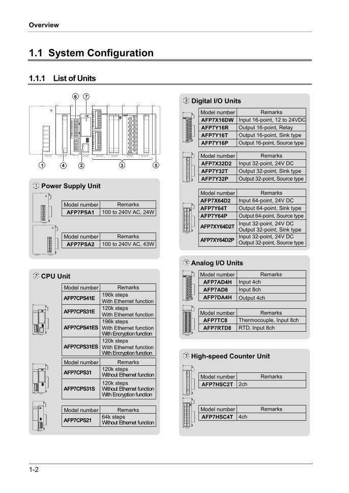
1.1 System Configuration
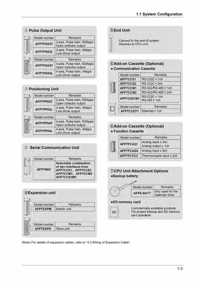
1.1.1 List of Units
Digital I/O UnitsModel numberAFP7X16DW
RemarksInput 16-point, 12 to 24VDC
AFP7Y16R Output 16-point, RelayAFP7Y16T Output 16-point, Sink typeAFP7Y16P Output 16-point, Source type
Model number
AFP7XY64D2T
Remarks
Input 32-point, 24V DCOutput 32-point, Sink type
AFP7X64D2 Input 64-point, 24V DCAFP7Y64T Output 64-point, Sink typeAFP7Y64P Output 64-point, Source type
AFP7XY64D2P Input 32-point, 24V DCOutput 32-point, Source type
Model numberAFP7X32D2
RemarksInput 32-point, 24V DC
AFP7Y32T Output 32-point, Sink typeAFP7Y32P Output 32-point, Source type
Power Supply Unit
Model numberAFP7PSA1
Remarks100 to 240V AC, 24W
Model numberAFP7PSA2
Remarks100 to 240V AC, 43W
1 3 524
6 7
AFP7AD4HAFP7AD8 Input 8chAFP7DA4H
AFP7TC8 Thermocouple, Input 8chAFP7RTD8 RTD,Input 8ch
High-speed Counter Unit
Model numberAFP7HSC2T
Remarks2ch
Model numberAFP7HSC4T
Remarks4ch
Analog I/O UnitsModel number Remarks
Input 4ch
Output 4ch
Model number Remarks
CPU Unit
AFP7CPS41E 196k stepsWith Ethernet function120k stepsWith Ethernet functionAFP7CPS31E
AFP7CPS41ES
AFP7CPS31ES120k stepsWith Ethernet functionWith Encryption function
196k stepsWith Ethernet functionWith Encryption function
120k stepsWithout Ethernet functionAFP7CPS31
120k stepsWithout Ethernet functionWith Encryption function
AFP7CPS31S
64k stepsWithout Ethernet functionAFP7CPS21
RemarksModel number
RemarksModel number
RemarksModel number
1.1 System Configuration
1-3
(Note) For details of expansion cables, refer to “4.3 Wiring of Expansion Cable”.

1-4
Overview
1.2 Restrictions on Combinations of Units
1.2.1 CPU Unit Type
Usable functions and combinations of units are limited according to types of CPU units as follows.
Item Supported function
CPU type CPS41E CPS31E CPS31 CPS21
Security enhancement type CPS41ES CPS31ES CPS31S
No corresponding
model
Program capacity (step) (Note 1) 196k (51k to 234k)
120k (32k to 121k)
120k (32k to 121k)
64k (32k / 64k)
Data register (word) (Note 1) 262k (999k to 65k)
131k (589k to 131k)
131k (589k to 131k)
131k (262k / 131k)
Hold area Max. 262k Max. 262k Max. 262k Max. 131k
Maximum number of PBs (Note 1) 392 (468 to 103)
243 (243 to 64)
243 (243 to 64)
128 (128 / 64)
Ethernet function Built-in Built-in Not available Not available SD memory card Usable Unusable Logging Available when SD memory card is mounted. Not available
Trace Available Available
Standard COM port
Terminal block 6P 5P COM0 port Available Available Terminal block for GT power supply
Either 5 V or 24 V can be used. Only 5 V
Combination of units
Power supply unit Available Not available Expansion master Expansion slave
Available Not available
Other units Add-on cassettes
Available
Battery Option (For clock/calendar) Unsable
Calendar timer Available (When a bettery is installed) Available (Note 2)
Size of CPU unit alone (Width) 40 mm 34 mm (Note 1) The program capacity, data registers and maximum number of program blocks (PBs) vary according to the
memory configuration settings. The values in the above table are default values, and values in parentheses are fluctuation ranges. Select from each setting patterns; Five for CPS41*, Four for CPS31*, Two for CPS21.
(Note 2) The Calendar timer can be activated by supplying the power to the unit for at least 30 minutes for charging the built-in capacitor even if a no battery is used. (For CPS4*/CPS3*, approx. one week. For CPS21, approx. two weeks.)

1.2 Restrictions on Combinations of Units
1-5
1.2.2 Common Restrictions on Each Unit
You can use FP7 series combining the CPU unit with optional input/output units and intelligent units. Up to 16 input/output units and intelligent units can be connected.
Make sure to connect an end unit to the end of the system.
You can either connect a power supply unit for system driving power, or directly supply power from an external 24 V DC power supply to the CPU unit. See “1.4 Selection of Power Supply and Restrictions on Combination“ for restrictions on combination.
For using an SD memory card, it is recommended to select a connector-type unit as a unit installed to the right of the CPU unit in order to prevent interference with the wirings of the unit.
(1) Power supply unit (2) CPU unit (3) Unit (4) End unit
1.2.3 Restrictions on the Number of Installed Units
There are following restrictions depending on units to be used. Unit type Number of installed units Remarks Power Supply Unit, CPU Unit Max. 1 unit Serial Communication Unit Max. 8 units

1-6
Overview
1.2.4 Restrictions on the Combination of Extension Cassettes
There are following restrictions depending on units and cassettes to be used.
Unit type Number of attachable cassettes
Attachable add-on cassettes Communication
cassette AFP7CCS* AFP7CCM*
Communication cassette
AFP7CCET
Application cassette AFP7FC*
CPU Unit Max. 1 unit Attachable Attachable Attachable Serial Communication Unit
Max. 2 units per unit Attachable Not attachable Not attachable
1.2.5 Restrictions on Communication Functions to be Used
There are the following restrictions on functions to be used when using the SCU or ET-LAN that is built in the CPU unit, or the serial communication unit (SCU).
Function to be used Restrictions
PLC link function
Up to two communication ports can be used. For using two ports, allocate different link areas to them. SCU built-in the CPU unit (COM.1 port) Serial communication unit (COM.1 port)
MEWTOCOL-COM master MODBUS-RTU master
A maximum of 16 communication ports and the number of connections in combination can be used simultaneously. SCU built-in the CPU unit (COM.1 port to COM. 2 port) Serial communication unit (COM.1 port to COM.4 port) ET-LAN built-in the CPU unit (User connections 1 to 16)
MEWTOCOL-COM slave MEWTOCOL7-COM slave MODBUS-RTU slave
A maximum of 15 communication ports and the number of connections in combination can be used simultaneously. SCU built-in the CPU unit (COM.1 port to COM. 2 port) Serial communication unit (COM.1 port to COM.4 port) ET-LAN built-in the CPU unit
(System connections 1 to 4 / User connections 1 to 16)
General-purpose communication There is no restriction.

1.2 Restrictions on Combinations of Units
1-7
1.2.6 Unit to be Used and Applicable Versions
For using each unit, the following versions of CPU unit and FPWINGR7 are required.
CPU Unit and FPWIN GR7
Unit type Applicable versions
Remarks CPU unit FPWINGR7
CPU unit CPS4*/CPS3*
Ver.1 Ver.1.0 or later
Ver.2 or later Ver.2.0 or later Ver.3.0 or later Ver.2.4 or later Ver.3.2 or later Ver.2.5 or later
CPS21 Ver.1.0 or later Ver.2.7 or later (Note 1) As for the CPU units (CPS4*/CPS3*) Ver.2 or later, the firmware of the CPU units can be upgraded with
"FP7 CPU Unit Upgrade Tool". For details, see our web site. (Note 2) FPWIN GR7 can be upgraded with "FPWIN GR7 Difference file". For details, see our web site.
Intelligent Unit
Unit type Applicable versions
Remarks CPU unit
FPWINGR7 CPS4*/CPS3* CPS21
FP7 High-speed Counter Unit Ver.1.2 or later Ver.1.0 or later Ver.1.2 or later (Note 1) FP7 Serial Communication Unit Ver.1.2 or later Ver.1.0 or later Ver.1.3 or later FP7 Communication Cassette (Ethernet type) Ver.1.3 or later Ver.1.0 or later Ver.1.0 or later (Note 2)
FP7 Analog I/O Cassette, Analog Input Cassette, Thermocouple Input Cassette
Ver.2.0 or later Ver.1.0 or later Ver.2.0 or later
FP7 Pulse Output Unit Ver.2.0 or later Ver.1.0 or later Ver.2.0 or later Thermocouple Multi-analog Input Unit RTD Input Unit
Ver.2.0 or later Ver.1.0 or later Ver.2.3 or later
FP7 Analog Input Unit (AFP7AD8) Ver.3.1 or later Ver.1.0 or later Ver.2.4 or later
FP7 Expansion Master Unit FP7 Expansion Slave Unit
Ver.3.1 or later — Ver.2.4 or later
(Note 1) For using the high-speed counter unit and the positioning unit in combination, and for using the interrupt function with the high-speed counter unit, the positioning unit Ver.1.1 or later is required.
(Note 2) Configurator WD should be Ver.1.7 or later.

1-8
Overview
1.3 Restrictions on Using Expansion Unit
1.3.1 Configuration When Using Expansion Unit
In FP series, blocks in which units are combined with the expansion master unit and expansion slave units can be added.
From 0 to 16 I/O units and intelligent units can be combined in one block.
Up to 3 expansion blocks can be connected to one CPU unit.
5
(a)
(b)
(b)
(b)
(1) (3)
(2) (3)
(2)
(2)
(4)
(5)
(5)
(3)
(a) Base block (1) Expansion master unit (3) Expansion cable
(b) Expansion block (2) Expansion slave unit (4) Dummy connector (5) Earth wire of
expansion cable

1.3 Restrictions on Using Expansion Unit
1-9
1.3.2 Restrictions on Combinations of Units
Combinations of base block Install the expansion master unit AFP7EXPM on the left-hand side of the CPU unit.
Install the power supply unit on the left-hand side of the expansion master unit AFP7EXPM as necessary.
(1) Power supply unit (2) Expansion
master unit (3) CPU unit (4) Unit (5) End unit
Combinations of expansion block Install the expansion slave unit AFP7EXPS on the left-hand side of the CPU unit.
Install the power supply unit on the left-hand side of the expansion master unit AFP7EXPM if used.
(1) Power supply unit (2) Expansion
slave unit (4) Unit (5) End unit
Base block and expansion block common restrictions Make sure to connect the end unit to the right side of the terminal unit.
As a power supply for driving the system, you can either connect the power supply unit used at 100 V/230 V AC, or directly supply 24 V DC power to the CPU unit and expansion slave units. For the restrictions on combinations, refer to “1.4 Selection of Power Supply and Restrictions on Combination“.

1-10
Overview
1.3.3 Installation Position of Units and Access Time
Restrictions on installation position of units There is no restriction on the installation position of each unit in FP7 series. However, the
access time to the units installed in the expansion block is longer than that to the units installed in the base block as shown in the table below, and it affects the scan time.
When large-volume data access is assumed with a communication system unit, a unit in which interrupt occurs or user programs, it is recommended to install the target units in the base block. It enables to decrease the scan time relatively.
Difference in access time between installation positions of units
Installation position
Access time Remarks
Time per word Ratio to base block
Base block 0.47 s/word Even
Expansion block (Short distance mode)
2.5 s/word 5.3 times
The total length of expansion cabels is 9 m or less. The LED "SP0" on the expansion master unit turns on.
Expansion block (Long distance mode)
4.1 s/word 8.7 times
The total length of expansion cabels is 10 m to 30 m. The LED "SP1" on the expansion master unit turns on.
(Note 1) The values in the above table indicate each time which the CPU unit accesses the units installed in each block via bus in the I/O refresh processing or operation processing. The scan time that an operation processing time and base time are added can be confirmed in the status display dialog blox of the tool software.
1.3.4 Restrictions on Configuration Capacity
Unit configuration capacity If units in which a lot of configuration data are set such as a positioning unit are used in the
expansion block a lot, the configuration capacity may exceed the capacity that the CPU unit can handle.
Check the configuration capacity in the I/O map dialog box of the tool software in advance.
The configuration capacity varies according to the functions and settings used in each unit. Also, the maximum registration capacity to be assigned depends on the number of installed expansion units.
1.3 Restrictions on Using Expansion Unit
1-11
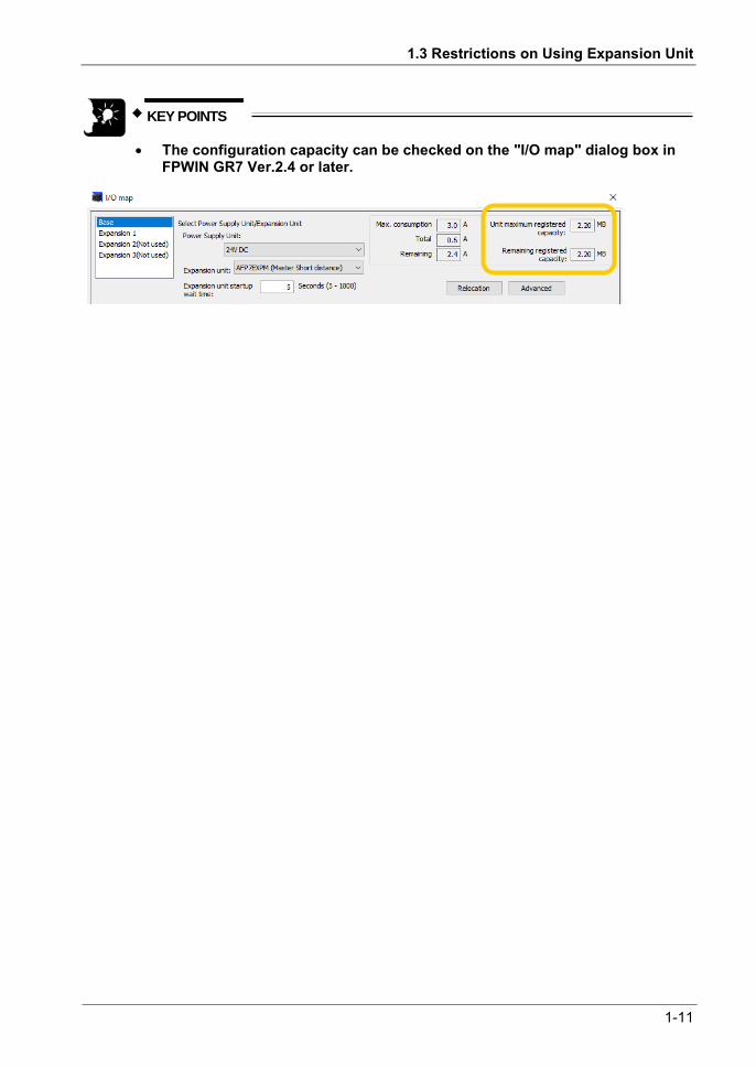
KEY POINTS
The configuration capacity can be checked on the "I/O map" dialog box in FPWIN GR7 Ver.2.4 or later.

1-12
Overview
1.4 Selection of Power Supply and Restrictions on Combination
1.4.1 Power Supply for Internal Circuit
Restrictions on combination of power supply for internal circuit and units Power for internal circuit is supplied from a power supply terminal of the power supply unit or
the CPU unit, or a power supply terminal of the expansion slave unit.
Select units within the respective restrictions indicated below. When a power supply unit is used When no power supply unit is used
Select units so that the sum of internal current consumptions of connected input/output units and intelligent units does not exceed the capacity of the power supply unit.
Select units so that the sum of internal current consumptions of connected input/output units and intelligent units does not exceed max. 2 A or 3 A (Note 1).
(Note 1) The allowable current without the power supply unit varies according to the model numbers of CPU unit. Refer to the next page.
(Note 2) The allowable current of the expansion slave unit without the power supply unit is max. 3 A.
Selection of a 24V DC power supply Select a power supply larger than the capacity of the units.In the minimum configuration,
select a power supply of 24 W or larger.
In order to protect the unit against abnormal voltage from the power supply line, the power supply should be an insulated type, and should be enclosed within a protective circuit.
If using a power supply device without an internal protective circuit, always make sure power is supplied to the unit through a protective element such as a fuse.
1.4 Selection of Power Supply and Restrictions on Combination
1-13
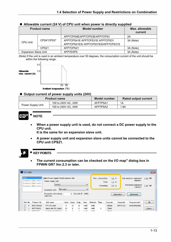
Allowable current (24 V) of CPU unit when power is directly supplied Product name Model number Max. allowable
current
CPU Unit CPS4*CPS3*
AFP7CPS4E/AFP7CPS3E/AFP7CPS3 2A AFP7CPS41E AFP7CPS31E AFP7CPS31 AFP7CPS41ES/ AFP7CPS31ES/AFP7CPS31S
3A (Note)
CPS21 AFP7CPS21 3A (Note) Expansion Slave Unit AFP7EXPS 3A (Note)
(Note) If the unit is used in an ambient temperature over 50 degrees, the consumption current of the unit should be within the following range.
Output current of power supply units (24V) Product name Model number Rated output current
Power Supply Unit 100 to 240V AC, 24W AFP7PSA1 1A 100 to 240V AC, 43W AFP7PSA2 1.8A
NOTE
When a power supply unit is used, do not connect a DC power supply to the
CPU unit. It is the same for an expansion slave unit.
A power supply unit and expansion slave units cannot be connected to the CPU unit CPS21.
KEY POINTS
The current consumption can be checked on the I/O map" dialog box in FPWIN GR7 Ver.2.3 or later.
1-14
Overview
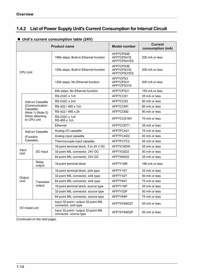
1.4.2 List of Power Supply Unit's Current Consumption for Internal Circuit
Unit’s current consumption table (24V)
Product name Model number Current consumption (mA)
CPU Unit
196k steps, Built-in Ethernet function AFP7CPS4E AFP7CPS41E AFP7CPS41ES
200 mA or less
120k steps, Built-in Ethernet function AFP7CPS3E AFP7CPS31E AFP7CPS31ES
200 mA or less
120k steps, No Ethernet function AFP7CPS3 AFP7CPS31 AFP7CPS31S
200 mA or less
64k steps, No Ethernet function AFP7CPS21 150 mA or less
Add-on Cassette (Communication Cassette) (Note 1) (Note 2) When attaching to CPU unit
RS-232C x 1ch AFP7CCS1 35 mA or less RS-232C x 2ch AFP7CCS2 60 mA or less RS-422 / 485 x 1ch AFP7CCM1 60 mA or less RS-422 / 485 x 2h AFP7CCM2 90 mA or less RS-232C x 1ch RS-485 x 1ch AFP7CCS1M1 70 mA or less
Ethernet AFP7CCET1 35 mA or less
Add-on Cassette (Function Cassette)
Analog I/O cassette AFP7FCA21 75 mA or less Analog input cassette AFP7FCAD2 40 mA or less
Thermocouple input cassette AFP7FCTC2 45 mA or less
Input Unit DC Input
16-point terminal block, 5 to 24 V DC AFP7X16DW 25 mA or less 32-point MIL connector, 24V DC AFP7X32D2 30 mA or less 64-point MIL connector, 24V DC AFP7X64D2 35 mA or less
Output Unit
Relay output 16-point terminal block AFP7Y16R 180 mA or less
Transistor output
16-point terminal block, sink type AFP7Y16T 35 mA or less 32-point MIL connector, sink type AFP7Y32T 50 mA or less 64-point MIL connector, sink type AFP7Y64T 75 mA or less 16-point terminal block, source type AFP7Y16P 35 mA or less 32-point MIL connector, source type AFP7Y32P 50 mA or less 64-point MIL connector, source type AFP7Y64P 75 mA or less
I/O mixed unit
Input 32-point / output 32-point MIL connector, sink type AFP7XY64D2T 55 mA or less
Input 32-point / output 32-point MIL connector, source type AFP7XY64D2P 55 mA or less
(Continued on the next page)

1.4 Selection of Power Supply and Restrictions on Combination
1-15
Product name Model number Current consumption (mA)
Analog Input Unit 4ch AFP7AD4H 100 mA or less 8ch AFP7AD8 85 mA or less
Analog Output Unit 4ch AFP7DA4H 250 mA or less
Thermocouple Multi-analog Input Unit AFP7TC8 80 mA or less RTD Input Unit AFP7RTD8 65 mA or less
High-speed Counter Unit
2-ch type AFP7HSC2T 65 mA or less 4-ch type AFP7HSC4T 65 mA or less
Pulse Output Unit
2-axis, open collector output AFP7PG02T 65 mA or less 4-axis, open collector output AFP7PG04T 65 mA or less
2-axis, line driver output AFP7PG02L 65 mA or less
4-axis, line driver output AFP7PG04L 65 mA or less
Positioning Unit
2-axis, open collector output AFP7PP02T 120 mA or less 4-axis, open collector output AFP7PP04T 120 mA or less 2-axis, line driver output AFP7PP02L 120 mA or less 4-axis, line driver output AFP7PP04L 120 mA or less
Serial Communication Unit AFP7NSC 50 mA or less
Extension Cassette (Communication Cassette) (Note 1) (Note 2) When attaching to Serial Communication Unit
RS-232C x 1ch AFP7CCS1 20 mA or less RS-232C x 2ch AFP7CCS2 40 mA or less RS-422 / 485 x 1ch AFP7CCM1 30 mA or less
RS-422 / 485 x 2h AFP7CCM2 60 mA or less RS-232C x 1ch RS-485 x 1ch AFP7CCS1M1 50 mA or less
PHLS master unit AFP7RMTM 85 mA or less Programmable display GT series (5V DC type) (Note 3) - 100 mA or less Expansion Master Unit (Note4) AFP7EXPM 120 mA or less Expansion Slave Unit (Note4) AFP7EXPS 100 mA or less
(Note 1) Power consumption indicated under "Add-on Cassette" refers to the current consumption increment of the CPU unit following addition of the relevant cassette.
(Note 2) The consumption current of add-on cassette (communication cassette) varies according to the unit to which the cassette is attached (CPU unit or serial communication unit).
(Note 3) Power consumption indicated under "Display" refers to the current consumption increment of the CPU unit following connection of a GT series display (5V power supply type) to the GT power supply terminal of the CPU unit. For GT series displays (24V power supply type), please see their respective hardware specifications.
(Note 4) The current consumption of the expansion master unit and the expansion slave unit depends on the expansion cables used.
1-16
Overview
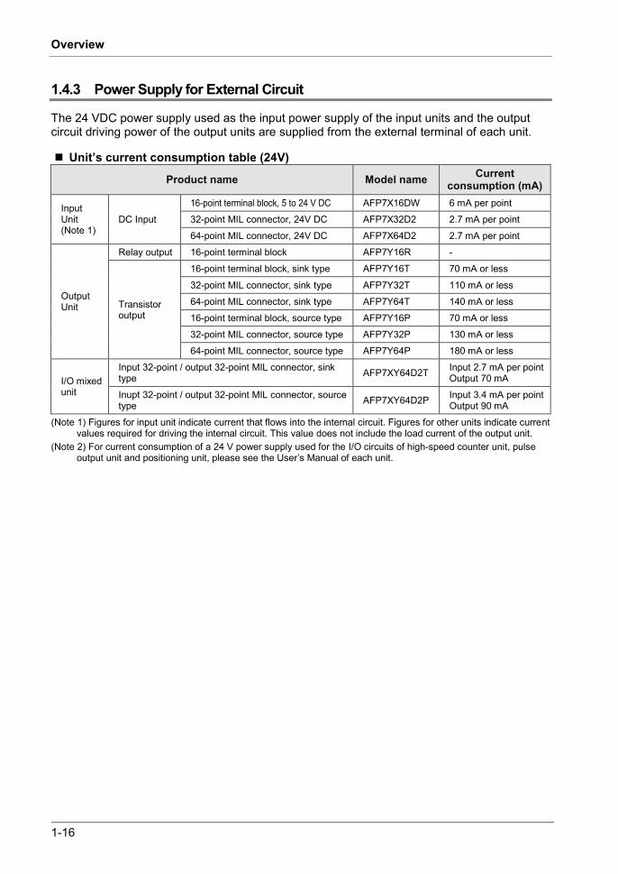
1.4.3 Power Supply for External Circuit
The 24 VDC power supply used as the input power supply of the input units and the output circuit driving power of the output units are supplied from the external terminal of each unit.
Unit’s current consumption table (24V)
Product name Model name Current consumption (mA)
Input Unit (Note 1)
DC Input 16-point terminal block, 5 to 24 V DC AFP7X16DW 6 mA per point 32-point MIL connector, 24V DC AFP7X32D2 2.7 mA per point 64-point MIL connector, 24V DC AFP7X64D2 2.7 mA per point
Output Unit
Relay output 16-point terminal block AFP7Y16R -
Transistor output
16-point terminal block, sink type AFP7Y16T 70 mA or less
32-point MIL connector, sink type AFP7Y32T 110 mA or less 64-point MIL connector, sink type AFP7Y64T 140 mA or less 16-point terminal block, source type AFP7Y16P 70 mA or less 32-point MIL connector, source type AFP7Y32P 130 mA or less 64-point MIL connector, source type AFP7Y64P 180 mA or less
I/O mixed unit
Input 32-point / output 32-point MIL connector, sink type AFP7XY64D2T Input 2.7 mA per point
Output 70 mA Inupt 32-point / output 32-point MIL connector, source type AFP7XY64D2P Input 3.4 mA per point
Output 90 mA (Note 1) Figures for input unit indicate current that flows into the internal circuit. Figures for other units indicate current
values required for driving the internal circuit. This value does not include the load current of the output unit. (Note 2) For current consumption of a 24 V power supply used for the I/O circuits of high-speed counter unit, pulse
output unit and positioning unit, please see the User’s Manual of each unit.

1.5 Programming Tools
1-17
1.5 Programming Tools
Required tools
1. Tool software FPWIN GR7 Dedicated to the FP7 series
Used for program editing, debugging and documentation.
2. PC connection cable Use a commercial cable.
Cable type Length USB 2.0 cable (A:miniB) Max. 5m

1-18
Overview

2 Names and Functions of
Parts

2-2
Names and Functions of Parts
2.1 CPU Unit (CPS4*/CPS3*)
(1)
(13)
(12)
(11)
(10)
(9)
(8)
(7)
(6)
(2)
(3)
(4)
(5)
(1)
(2)
(3)
(4)
(5)
(13)
(12)
(11)
(10)
(9)
(8)
(7)
(6)
CPS41E/CPS31E/CPS31 CPS41ES/CPS31ES/CPS31S CPS4E/CPS3E/CPS3
Names and functions of parts
(1) Operation monitor LEDs Body display LED
color Contents
- Blue Turns on when the CPU unit power is ON. RUN Green Turns on in the RUN mode. Blinks during forced input/output. PROG. Green Turns on in the PROG. mode.
COM.0 SD Green Turns on while sending data from the COM.0 port. RD Green Turns on while receiving data from the COM.0 port.
SD Green Flashes while accssing an SD memory card. Also flashes while logging data into the unit memory with the logging function.
CARD Green Turns on while operation by the SD memory card is selected. COPY Green Turns on during the COPY operation. ERROR Red Turns on when an error has been detected through self-diagnosis.
ALARM Red Turns on if a hardware error occurs, or operation slows because of the program, and the watchdog timer is activated.
Note) The layout of the operation monitor LEDs in Ver.1 of the CPU unit is different from that in Ver.2 or later.
(2) Add-on cassette (Optional) Attach an optional Add-on Cassette (Communication Cassette or Function Cassette).
(3) COM0 port terminal 3-wire RS-232C port

2.1 CPU Unit (CPS4*/CPS3*)
2-3
(4) GT power supply terminal For our programmable display "GT series", either 5V DC output or 24V DC output can be used.
(5) Power supply connector Connected with an external power supply (24V DC); When a power supply unit is used, do not connect this.
(6) DIN hook Used for fixation on the DIN rail.
(7) LAN port (CPS4E、CPS41E、CPS41ES、CPS3E、CPS31E、CPS31ES) Port for connection to Ethernet LAN
(8) USB port Connected to a PC using the tool software
(9) Unit connectors Connected to the internal circuit of I/O units and intelligent units
(10) Dip switches (CPS4E、CPS41E、CPS41ES) Do not change the setting. The switches are all set to OFF at the factory.
(11) Card cover 11-4
11-3
(Note)
11-1
11-2
Number Name Functions 11-1 Battery holder Attach a battery. 11-2 SD memory card slot Insert an SD memory card.
11-3 Card operation switch Select between ROM operation or SD operation. By selecting SD operation, provisional operation from the SD memory card becomes possible.
11-4 Power supply connector Connected to a power supply connector
2-4
Names and Functions of Parts
(Note) Do not apply an excessive force to the card cover when opening or closing it or when the cover is left open. Otherwise, the cover attachment part will be deformed to cause malfunction in the cover recognition switch mounted inside the product.
(12) Mode switch Switch position Operation Mode
RUN (left) Set to the RUN mode. The program is executed and operation begins. PROG. (middle) Set to the PROGRAM mode.
COPY (right, momentary) When the switch is set to COPY, a project stored in the internal RAM / ROM1 is transmitted to ROM2 as a backup project.
(Note) Whether the switch is set to RUN or PROG., the mode can be switched through remote operation from the programming tool. When power is turned on again, it operates in the mode set on the switch.
(13) Fixing hook Used for fixing a power supply unit to the CPU unit.

2.2 CPU Unit (CPS21)
2-5
2.2 CPU Unit (CPS21)
CPS21
Names and Functions of Parts
(1) Operation monitor LEDs
LED name LED color Data to Display
- Blue Lit when the CPU unit is turned ON.
RUN Green Lit when the CPU unit is in RUN mode. Lit when the forced /O function is executed.
PROG. Green Lit when the CPU unit is in PROG mode. ERROR Red Lit when an error is detected by self-diagnosis.
COM.0 SD Green Lit when data is sent from the COM0 port. RD Green Lit when data is received from the COM0 port.
COPY Green Lit when copying data.
ALARM Red This lights if a hardware error occurs, or operation slows because of the program, and the watchdog timer is activated.
(2) Add-on cassette (Option) Attach an optional Add-on Cassette (Communication Cassette or Function Cassette).
(3) DIN hook Used for installing the unit on a DIN rail.
(4) Power supply connector Used for connecting to an external power supply (24 V DC).
(5) Power supply for GT For our programming display "GT series", 5V DC output can be used.

2-6
Names and Functions of Parts
(6) COM0 port terminal Three-wire RS-232C port.
(7) Unit connector Used for connecting an I/O unit or intelligent unit. An end unit is fitted when the unit is shipped.
(8) USB port Used for connecting with a PC on which tool software is used.
(9) Mode switch Switch position Operation mode
RUN (Left) Sets to RUN mode. The program is executed and operation begins. PROG. (Right) Sets to PROG mode.
(Note 1) Whether the switch is set to RUN or PROG., the mode can be switched through remote operation from the programming tool. When power is turned on again, it operates in the mode set on the switch.
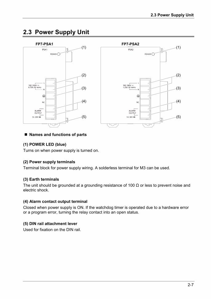
2.3 Power Supply Unit
2-7
2.3 Power Supply Unit
FP7-PSA1 FP7-PSA2(1)
(2)
(3)
(4)
(5)
(1)
(2)
(3)
(4)
(5)
Names and functions of parts
(1) POWER LED (blue) Turns on when power supply is turned on.
(2) Power supply terminals Terminal block for power supply wiring. A solderless terminal for M3 can be used.
(3) Earth terminals The unit should be grounded at a grounding resistance of 100 Ω or less to prevent noise and electric shock.
(4) Alarm contact output terminal Closed when power supply is ON. If the watchdog timer is operated due to a hardware error or a program error, turning the relay contact into an open status.
(5) DIN rail attachment lever Used for fixation on the DIN rail.
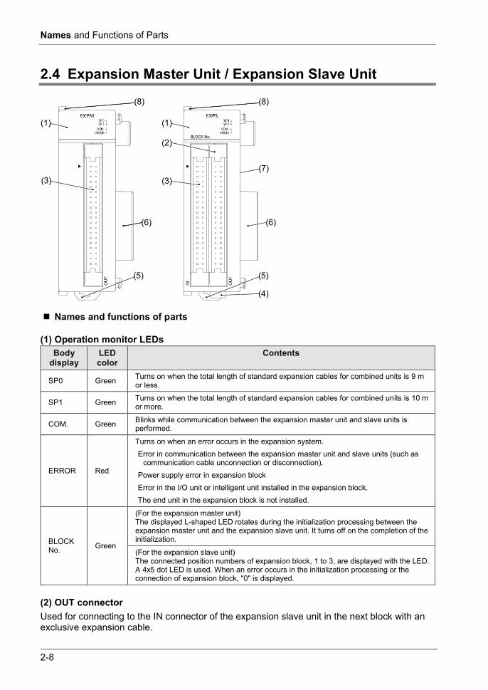
2-8
Names and Functions of Parts
2.4 Expansion Master Unit / Expansion Slave Unit
(1) (1)
(2)
(3)
(8) (8)
(7)
(6) (6)
(5) (5)
(4)
(3)
Names and functions of parts
(1) Operation monitor LEDs Body
display LED color
Contents
SP0 Green Turns on when the total length of standard expansion cables for combined units is 9 m or less.
SP1 Green Turns on when the total length of standard expansion cables for combined units is 10 m or more.
COM. Green Blinks while communication between the expansion master unit and slave units is performed.
ERROR Red
Turns on when an error occurs in the expansion system. Error in communication between the expansion master unit and slave units (such as
communication cable unconnection or disconnection). Power supply error in expansion block Error in the I/O unit or intelligent unit installed in the expansion block. The end unit in the expansion block is not installed.
BLOCK No. Green
(For the expansion master unit) The displayed L-shaped LED rotates during the initialization processing between the expansion master unit and the expansion slave unit. It turns off on the completion of the initialization.
(For the expansion slave unit) The connected position numbers of expansion block, 1 to 3, are displayed with the LED. A 4x5 dot LED is used. When an error occurs in the initialization processing or the connection of expansion block, "0" is displayed.
(2) OUT connector Used for connecting to the IN connector of the expansion slave unit in the next block with an exclusive expansion cable.

2.4 Expansion Master Unit / Expansion Slave Unit
2-9
(3) IN connector Used for connecting to the OUT connector of the expansion slave unit in the previous block with an exclusive expansion cable.
(4) Power supply connector (AFP7EXPS only) Connected with an external power supply (24V DC); When a power supply unit is used, do not connect this.
(5) DIN hook Used for fixing the unit on the DIN rail.
(6) Unit connector Used for connecting the internal circuit of an I/O unit or intelligent unit. The end unit is attached with shipment.
(7) Dip switches Do not change the setting. The switches are all set to OFF at the factory.
(8) Fixing hook Used for fixing a power supply unit

2-10
Names and Functions of Parts

3 I/O Number Allocation

3-2
I/O Number Allocation
3.1 Basics of I/O Allocation
3.1.1 How to Count the I/O Numbers
Counting and expression of the I/O numbers Since I/O numbers are handled in units of 16 points, they are expressed as a combination of a device type code and the lowest-digit of a decimal or hexadecimal number.
E.g. In the case of an external input, X0 to X9 and XA to XF are used.
3.1.2 Concept of I/O Number Allocation
Examples of I/O Number Allocation I/O numbers are determined by the status of unit attachment and the occupied I/O points allocated to respective units.
Starting word numbers of input/output units and intelligent units By default, the starting word number for the unit attached next to the CPU unit is set at "10",
and the I/O numbers start with X100 or Y100.
The starting word number for each unit can be freely changed in the "FP7 Configuration" menu of the tool software FPWIN GR7.
1 2 7 F <Decimal> 0, 1, 2, 3 ..... 9
<Hexadecimal> 0, 1, 2, 3 ..... 9, A, B ...F

3.1 Basics of I/O Allocation
3-3
How to count I/O numbers for units that have both inputs and outputs In the case of a unit that has both inputs and outputs (e.g. mixed input/output units, intelligent units), input numbers and output numbers start with the same value.
E.g. If input numbers for a mixed input/output unit are X100 to X11F, the unit's output numbers are set at Y100 to Y11F.
I/O numbers allocated to the CPU unit A fixed area is allocated to the COM port and the ET-LAN port.
NOTE
When the number of occupied input words is different from the number of
occupied output words, the larger number is allocated to the unit.
For using the user connections 17 to 216 by extending the number of user connections with the built-in ET-LAN in the CPU unit, 26-word area (WX11 to WX36/WY11 to WY36) is used as a flag for confirming the communication instruction SEND/RECV. Change the starting number of the CPU unit or another unit not to overlap I/O maps.
The starting numbers of I/O contacts of each unit including the CPU unit can be changed by the setting of tool software.

3-4
I/O Number Allocation
3.1.3 List of Occupied I/O Points for Each Unit
CPU Unit
Unit Type Model No. or Function
Occupied words (occupied I/O points)
Input Output
CPU Unit
SCU built-in CPU Unit Common 2 words (32 points) WX0-WX1
2 words (32 points) WY0-WY1
Communication Cassette (Ethernet type)
AFP7CCET1 4 words (64 points) WX0-WX3
2 words (32 points) WY0-WY1
Analog I/O Cassette AFP7FCA21 2 words (32 points) WX2 to WX3
1 word (16 points) WY2
Analog Input Cassette AFP7FCAD2 - Thermocouple Cassette AFP7FCTC2 - System reserved area Common WX4-WX5 WY4-WY5
Built-in ET-LAN in the CPU
ET-LAN common occupied area WX6 -
User connections 1 to 16
3 words (48 points) WX7-WX9
3 words (48 points) WY7-WY9
(Note 1) Input/output contacts of the CPU unit are allocated for using the functions of each cassette. Regardless of use of such functions, input occupies 10 words (160 points, WX0 to WX9) and output occupies 10 words (160 words, WY0 to WY9).
(Note 2) The starting numbers of I/O contacts of each unit including the CPU unit can be changed by the setting of the tool software.
CPU unit (Built-in ET-LAN extended connection)
Unit Type Model No. or Function Occupied words
(occupied I/O points) Input Output
CPU unit
Built-in ET-LAN in the CPU
User connections 1 to 16 WX7-WX9 WY 7-WY10
User connection
17 to 32 WX11 WY11-WY12 33 to 48 WX13 WY13-WY14 49 to 64 WX15 WY15-WY16 65 to 80 WX17 WY17-WY18 81 to 96 WX19 WY19-WY20 97 to 112 WX21 WY21-WY22 113 to 128 WX23 WY23-WY24 129 to 144 WX25 WY25-WY26 145 to 160 WX27 WY27-WY28 161 to 176 WX29 WY29-WY30 177 to 192 WX31 WY31-WY32 193 to 208 WX33 WY33-WY34 209 to 216 WX35 WY35-WY36
(Note 1) For using the user connections 17 to 216 by extending the number of user connections with the bult-in ET-LAN in the CPU unit, the above areas are used as flags confirming the transmission of the communication instruction SEND/RECV. Change the starting number of the CPU unit or another unit not to overlap I/O maps.
(Note 2) The area for user connections 1 to 16 occupies 4 words including flags for general-purpose communication. (Note 3) Occupied area in the area of user connections 17 to 216 varies according to the number of used
connections. (Note 4) The starting numbers of I/O contacts of each unit including the CPU unit can be changed by the setting of the
tool software.

3.1 Basics of I/O Allocation
3-5
I/O Unit
Unit Type Model number Occupied words
(occupied I/O points) Input Output
Input/Output Units
Input unit 16 points AFP7X16DW 1 word (16 points) Input unit 32 points AFP7X32D2 2 words (32 points) Input unit 64 points AFP7X64D2 4 words (64 points)
Output unit 16 points AFP7Y16R AFP7Y16T AFP7Y16P
1 word (16 points)
Output unit 32 points AFP7Y32T AFP7Y32P 2 words (32 points)
Output unit 64 points AFP7Y64T AFP7Y64P
4 words (64 points)
Mixed input/output units Input 32 points / Output 32 points
AFP7XY64D2T AFP7XY64D2P
2 words (32 points) 2 words (32 points)
Intelligent Unit
Unit Type Model number
Occupied words (occupied I/O points)
Input Output
Intelligent Unit
Analog Input Unit AFP7AD4H 8 words (128 points) 4 words (64 points) AFP7AD8 16 words (256 points) 8 words (128 points)
Analog Output Unit AFP7DA4H 4 words (64 points) 8 words (128 points) Thermocouple Multi-analog Input Unit AFP7TC8 16 words (256 points) 8 words (128 points)
RTD Input Unit AFP7RTD8 16 words (256 points) 8 words (128 points) High-speed Counter Unit
AFP7HSC2T 8 words (128 points) 4 words (64 point)
AFP7HSC4T
Pulse Output Unit
AFP7PG02T, AFP7PG02L 2 words (32 points) 2 words (32 points)
AFP7PG04T, AFP7PG04L 4 words (64 points) 4 words (64 points)
Positioning Unit
AFP7PP02T AFP7PP02L AFP7PP04T AFP7PP04L
12 words (196 points) 12 words (196 points)
Serial Communication Unit AFP7NSC 2 words (32 points) 2 words (32 points)
PHLS master unit AFP7PHLSM 63 words (1,008 points)
63 words (1,008 points)
(Note 1) The starting numbers of I/O contacts of each unit including the CPU unit can be changed by the setting of tool software.
(Note 2) As for the PHLS master unit, input occupies 63 words (1,008 points) and output occupies 63 words (1,008 points). The actual input/output points that can be used vary by the number of slave units that are connected, with the maximum of 1,008 points.

3-6
I/O Number Allocation
3.2 Optional Allocation Using FPWIN GR7
3.2.1 Registration of a Unit to be Used and the Starting Word Number
Allocation method The unit to be used and the starting I/O number are set in the following procedure.
PROCEDURE 1. From the menu bar, select "Option" "FP7 Configuration" "I/O map".
The "I/O map" dialog box is displayed.
2. Select and double-click Slot No. 0.
The “Unit selection” dialog box is displayed.

3.2 Optional Allocation Using FPWIN GR7
3-7
3. Confirm the installation position setting, and press the "OK" button. The CPU unit is registered in the I/O map. If the CPU unit is different, select "Tool" "Convert PLC Type" from the menu bar and change the type.
4. Select and double-click Slot No. 1. The "Unit selection" dialog box is displayed.
5. In the unit type field, select a unit to be attached.
Subsequently, input words and output words are automatically entered.
6. As necessary, enter the starting word number and press the [OK] button. The registered unit and the starting word number are included in the I/O map. A number that combines the starting word number registered for each unit and 0 to F becomes the starting I/O number.
7. Repeat registrations. 8. Press the [OK] button while the "FP7 configuration" dialog box is displayed.
KEY POINTS
The I/O map registered using FPWIN GR7 is downloaded into the CPU unit, together with other project information. If a difference with the actual units and/or attachment status is identified when power supply is turned on or during operation, such a difference is reported as a self-diagnosis error.
If a starting word number is not entered, the system automatically enters one.
Based on the starting word number allocated to each unit, I/O numbers are allocated.
The starting number of I/O numbers allocated to the internal functions of the CPU unit can be changed to another number from the word number 0.

3-8
I/O Number Allocation
3.2.2 Optional Settings in the “Unit Selection” Dialog Box
Input time constants Input time constants for an input unit or a mixed input/output unit can be changed as necessary. Select, and set for each unit, a desirable value from "No settings", 0.1, 0.5, 1.0, 5.0, 10.0, 20.0 or 70.0 ms. The selected time constants are added to the hardware-specific response time of each unit.
For details, please see the "FP7 Digital Input/Output Unit Users Manual".
Exclude this unit from the scope of verification. In general, this check box should be turned off.
If you want to exclude this unit from the scope of verification error temporarily for unit replacement or adjustment, turn on this check box.
Exclude this unit from the scope of I/O refresh. In general, this check box should be turned off. Input/output processing is performed at the
timing of I/O refresh in a normal scan.
By using operation devices "Direct input IN " or "Direct output OT", it becomes possible to directly perform input/output processing during operation, independent of normal I/O refresh. When this operation device is used, turn on the check box "Exclude this unit from the scope of I/O refresh".
By turning this check box on, all inputs and outputs of registered units are excluded from the scope of I/O refresh.

3.2 Optional Allocation Using FPWIN GR7
3-9
3.2.3 Settings When Using Expansion Unit
Make the settings according to the used configuration.
Selection of Power supply unit and Expansion unit Setting item Description Common to Base and Expansion 1-3
Power supply unit Select 24 V DC or a power supply unit according to the used configuration.
Base Expansion unit
AFPEXPM (Master, short distance): Select when the total length of expansion cables is 9 m or less. AFPEXPM (Master, long distance): Select when the total length of expansion cables is 10 m or more.
Expansion 1-3
Expansion unit Select AFP7EXPS (Slave).
Common to Base and Expansion 1-3
Expansion unit startup wait time
Set the wait time until the power to the expansion unit turns ON after the power to the CPU unit turned ON. A self-diagnostic error occurs when the power to the expansion unit does not turn on even after the elapse of the startup wait time. Communication via the USB port , COM port and LAN port of the CPU unit cannot be performed during the startup wait time. Setting range: 5 to 1800 secs, Default: 5 secs

3-10
I/O Number Allocation
3.3 Mount Allocation Using FPWIN GR7
3.3.1 Mount Registration of a Unit to be Used and the Starting Word Number
What is mount registration? If all units to be used are physically at hand, you can connect FPWIN GR7 online to the FP7 CPU unit, read the actual mount status, and complete registration.
Allocation method Mount registration of the unit to be used and the initial I/O number are set in the following procedure.
PROCEDURE 1. From the menu bar, select "Online" "Online Editing".
The screen is switched to the “Online Editing” mode.
2. Select "Option" "FP7 Configuration". 3. In the relevant field, select "I/O Map".
The "I/O Map" dialog box is displayed.
4. Press the [Mount] button. The mount status is read, and the read I/O map is registered in the CPU unit.
KEY POINTS
Following the mount registration operation, the system automatically reads the unit attachment status, formulates an I/O map, and enters the initial word number.
The I/O map that has been mount-registered using FPWIN GR7 is registered into the CPU unit, together with other project information. If a difference with the actual units and/or attachment status is identified when power supply is turned on or during operation, such a difference is reported as a self-diagnosis error.
If a starting word number is not entered, the system automatically enters one.
Based on the starting word number allocated to each unit, I/O numbers are allocated.

3.3 Mount Allocation Using FPWIN GR7
3-11
3.3.2 Changing the Starting Word Number
When you want to change the starting word number following mount registration, please take the following procedure.
Allocation method Changing the starting word number following mount registration should be performed in the following procedure. In the following procedure, it is assumed that an I/O map is already displayed.
PROCEDURE 1. On the "I/O Map", double click a unit for which the starting word number
should be changed.
2. Enter a desired starting word number and press the [OK] button.
The changed number is registered in the I/O map.
KEY POINTS
Once you change the starting word number using FPWIN GR7, the I/O map is changed from the initial status following mount registration. It is necessary to edit the I/O map online, or to download the project once again.
Pressing the "Reallocate" button with a desired slot selected displays the word No. reallocation dialog box.

3-12
I/O Number Allocation
3.4 I/O Map Registration
3.4.1 I/O Map Registration
What is I/O map registration? This refers to a status where I/O map information is registered in the CPU unit. To register an I/O map, the following methods are available.
Download an I/O map created through optional allocation using FPWIN GR7 into the CPU unit.
Perform "mount registration" operation in the online editing mode of FPWIN GR7.
3.4.2 I/O Map Clearance
How to clear an I/O map A registered I/O map can be cleared in the following procedure.
PROCEDURE 1. From the menu bar, select "Option" "FP7 Configuration". 2. In the relevant field, select "I/O Map".
The "I/O Map" dialog box is displayed.
3. Press [Initialize] button. The I/O map is initialized.
KEY POINTS
Once the [Initialize] button is pressed, other configuration information is also deleted.

4 Installation and Wiring

4-2
Installation and Wiring
4.1 Installation
4.1.1 Installation Environment and Space
Installation environment Operating environment (Use the unit within the range of the general specifications when installing) Ambient temperatures: 0 to +55 C Ambient humidity: 10 to 95%RH (at 25C, no-condensing) Pollution degree: 2
Altitude: 2,000m above sea level or lower
Overvoltage category: II or lower Installation location: In a control panel which has a protective construction IP54 or higher (made from metal that is of adequate strength) Do not use the unit in the following environments. Direct sunlight Sudden temperature changes causing condensation Inflammable or corrosive gas Excessive airborne dust, metal particles or saline matter Benzine, paint thinner, alcohol or other organic solvents or strong alkaline solutions such as ammonia or caustic soda Direct vibration, shock or direct drop of water. Influence from power transmission lines, high voltage equipment, power cables, power equipment, radio transmitters, or any other equipment that would generate high switching surges (100 mm or more)
Clearance In order to secure clearance for ventilation, ensure that the top and the bottom of the unit are
at least 50 mm away from other devices, wiring ducts, etc.
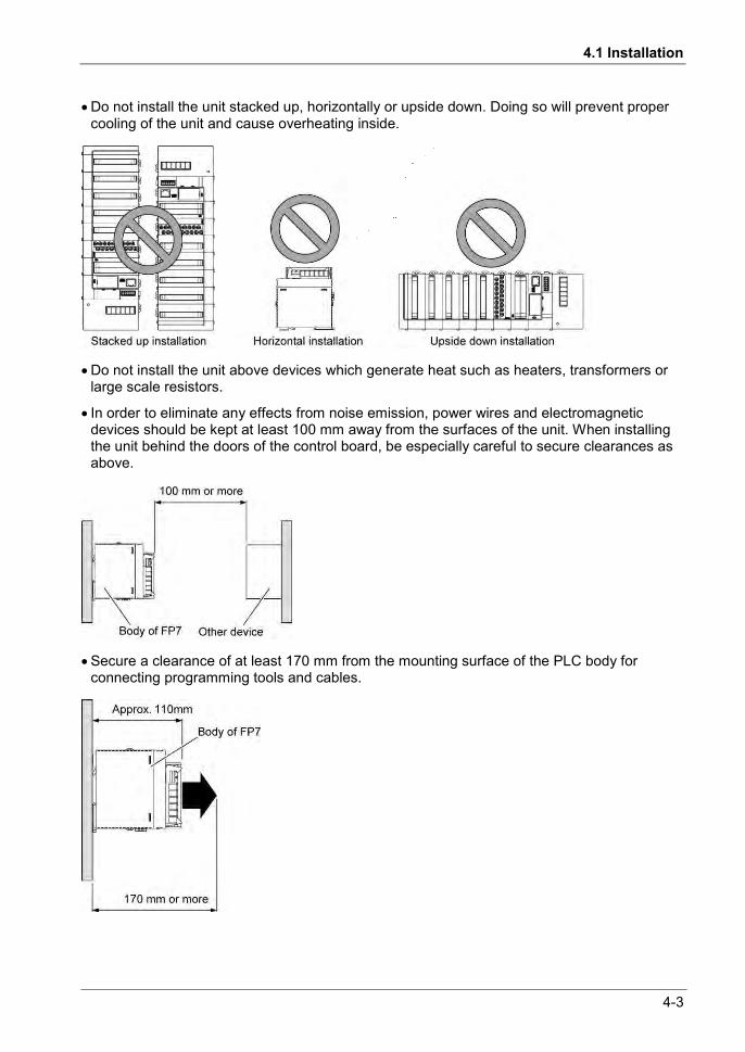
4.1 Installation
4-3
Do not install the unit stacked up, horizontally or upside down. Doing so will prevent proper cooling of the unit and cause overheating inside.
Do not install the unit above devices which generate heat such as heaters, transformers or large scale resistors.
In order to eliminate any effects from noise emission, power wires and electromagnetic devices should be kept at least 100 mm away from the surfaces of the unit. When installing the unit behind the doors of the control board, be especially careful to secure clearances as above.
Secure a clearance of at least 170 mm from the mounting surface of the PLC body for connecting programming tools and cables.
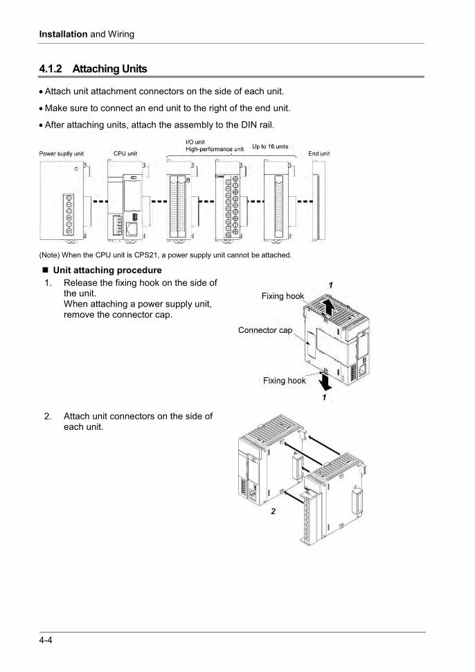
4-4
Installation and Wiring
4.1.2 Attaching Units
Attach unit attachment connectors on the side of each unit.
Make sure to connect an end unit to the right of the end unit.
After attaching units, attach the assembly to the DIN rail.
(Note) When the CPU unit is CPS21, a power supply unit cannot be attached.
Unit attaching procedure 1. Release the fixing hook on the side of
the unit. When attaching a power supply unit, remove the connector cap.
2. Attach unit connectors on the side of each unit.

4.1 Installation
4-5
3. Lock the fixing hook.
Unit removing procedure 1. Release the fixing hook on the side of
the unit.
2. Slide the unit horizontally to remove it.
NOTES
Make sure to turn off power supply before attaching a unit.
Do not directly touch the connector part of the unit.
Protect the connector part of the unit from stress.

4-6
Installation and Wiring
4.1.3 DIN Rail Attachment
DIN rail attachment procedure 1. Fully pull out the DIN rail attachment
lever on the back of the unit.
2. Fit the top of the unit attachment part into the DIN rail.
3. While pressing down the unit attachment part onto the DIN rail, fit the bottom of the unit attachment part into the DIN rail.
4. Push up the DIN rail attachment lever on the back of the unit until it clicks to lock.
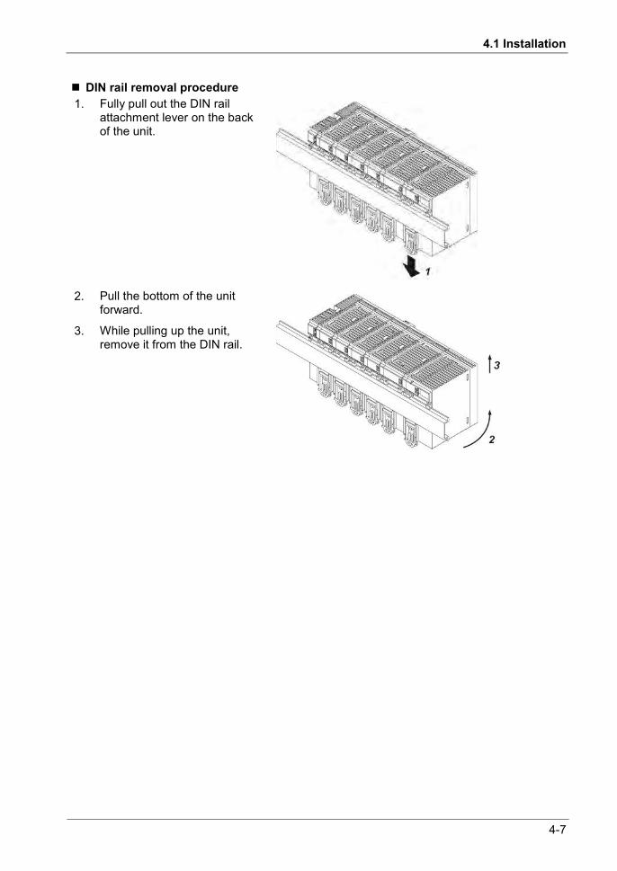
4.1 Installation
4-7
DIN rail removal procedure 1. Fully pull out the DIN rail
attachment lever on the back of the unit.
2. Pull the bottom of the unit forward.
3. While pulling up the unit, remove it from the DIN rail.

4-8
Installation and Wiring
4.2 Wiring the Power Supply
4.2.1 Common Precautions
To avoid the influence of noises Use a low noise power supply.
The inherent noise resistance is sufficient for the noise superimposed on the power wires, however, the noise can be attenuated further by using the isolation transformer.
Also, twist the power supply cables to minimize adverse effects from noise.
Keep the power supply wiring separate Wiring to the CPU unit, input devices, and power equipment should have separate wiring systems.
Measures regarding power supply sequence (start up sequence) Have the power supply sequence such that the power supply of PLC turns off before the
power supply for input and output.
If the input/output power supplies are turned off before the power PLC, the CPU unit will detect the input fluctuations and may begin an unscheduled operation.

4.2 Wiring the Power Supply
4-9
4.2.2 Wiring for Power Supply Units
Terminal layout for power supply units
Power supply voltage Confirm that the connected voltage is within the allowable range of the power supply.
Model number
Rated input voltage
Allowable voltage range
Rated output capacity
Rated output current
AFP7PSA1 100 to 240 V AC 85 to 264 V AC 24 W 1 A AFP7PSA2 100 to 240 V AC 85 to 264 V AC 43 W 1.8 A
Power supply cable Use a power supply wire of 2mm2 (AWG14) to minimize the voltage drop.
Suitable wires and tightening torque Terminal Suitable wires Tightening torque
Power supply terminal and ground terminal
AWG14 (2.0 mm2) 0.5 to 0.6 N∙m
Alarm output terminal AWG22 to 14 (0.3 mm2 to 2.0 mm2)
Suitable crimp terminal M3 terminal screws are used for the terminal. Use the following solderless terminals for wiring to the terminals.
Fork type terminals Round type terminal
Suitable crimp terminal Manufacturer Shape Part no. Suitable wires
J.S.T. Mfg Co.,Ltd
Round type 2-MS3 1.04 to 2.63 mm2
Fork type 2-N3A Round type 1.25-MS3
0.25 to 1.65 mm2 Fork type 1.25-B3A

4-10
Installation and Wiring
4.2.3 Wiring for the Power Supply Part of the CPU Unit
When the CPU unit is used with 24V DC power supply, perform wiring for power supply as follows.
Use the power supply cables (Part No.:AFPG805) that come with the unit to connect the power supply. Brown: 24V DC, Blue: 0V, Green: functional earth
Power supply part of the CPU unit
Blue: 0VBrown: +24V Green: Function earth
External power supplyFed from an external power supply 24V DC
Power supply cable (attached)
Power supply connector
Power supply voltage Confirm that the power supply voltage is within the allowable range of the power supply.
Rated input voltage
Allowable voltage range
Rated output capacity
24V DC 20.4 to 28.8 V DC At least 24 W
When a programmable display GT series is connected to the GT power supply terminal (24V) of the CPU unit, use it within the range of 21.6 to 26.4 V DC.
Selection of a power supply Referring to “1.4 Selection of Power Supply and Restrictions on Combination“, select a
power supply larger than the capacity of the unit. In the minimum configuration, select a power supply of 24 W or larger.
In order to protect the unit against abnormal voltage from the power supply line, the power supply should be an insulated type, and should be enclosed within a protective circuit. The regulator on the unit is a non-insulated type.
If using a power supply device without an internal protective circuit, always make sure power is supplied to the unit through a protective element such as a fuse.
4.2.4 Wiring of Power Supply Part of Expansion Slave Unit
When the power supply unit is not used, make the wiring for the power supply as well as the CPU unit with the power supply cable attached to AFP7EXPS.

4.2 Wiring the Power Supply
4-11
4.2.5 Grounding
Ground the instrument to ensure sufficient noise suppression.
The point of grounding should be as close to the PLC as possible. The ground wire should be as short as possible.
Sharing the ground with another device may have an adverse effect. Therefore, be sure that grounding is dedicated.
Earth terminals for an AC power supply unit should be grounded at a grounding resistance of 100 Ω or less.
When 24V DC is directly supplied to the CPU unit, ground the attached functional earth (Green).

4-12
Installation and Wiring
4.3 Wiring of Expansion Cable
4.3.1 Expansion Cable Type
Use the expansion cable AFP7EXPC** (sold separately) for connecting the expansion master unit AFP7EXPM and expansion slave unit AFP7EXPS, or connecting the expansion slave units AFP7EXPS together.
Model number Cable length AFP7EXPCR5 0.5 m AFP7EXPC01 1 m
AFP7EXPC03 3 m AFP7EXPC10 10 m
4.3.2 Connection of Function Earth Wire
A function earth wire is attached to the expansion cable. In order to avoid influence of noise, the function earth wire of the expansion cable must be grounded.
Make grounding as the same as that of the expansion block to which the connector with the function earth wire is connected.
(1) (2)(3)
(1) OUT side Connected to the OUT side of the expansion master unit AFPEXPM or expansion slave unit AFPEXPS.
(2) IN side Connected to the IN side of the expansion slave unit AFPEXPS.
(3) Function earth wire
Make grounding as the same as that of the expansion block to which the connector with the function earth wire is connected.
Do not use the expansion cable in the same raceway as other cables are placed.
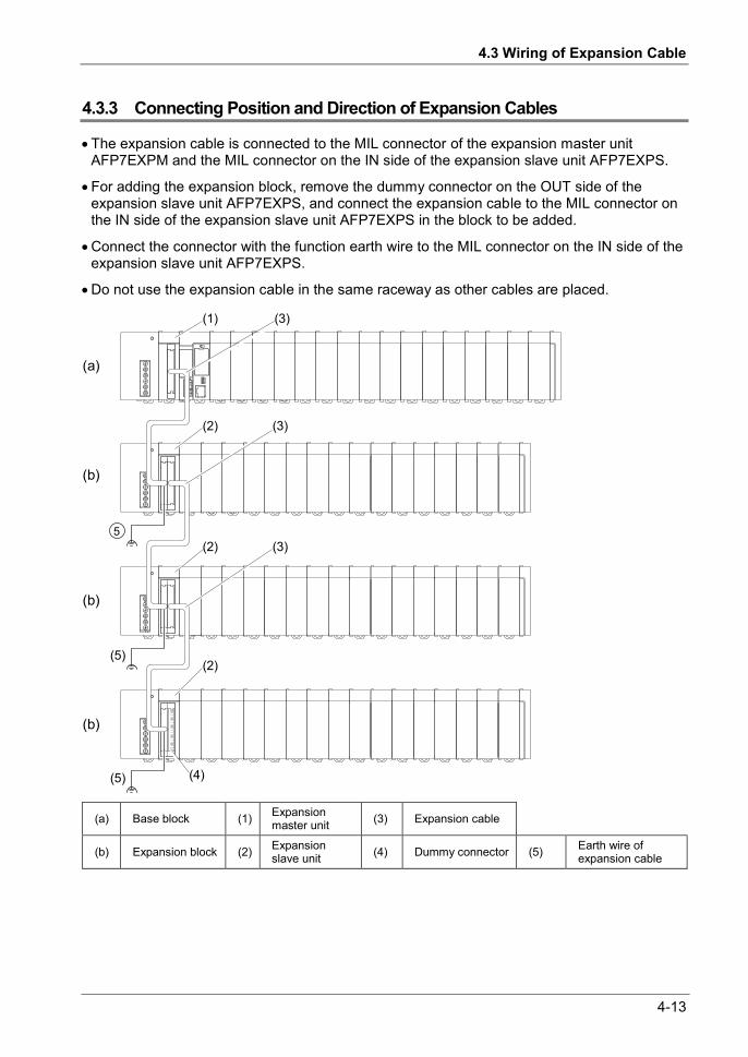
4.3 Wiring of Expansion Cable
4-13
4.3.3 Connecting Position and Direction of Expansion Cables
The expansion cable is connected to the MIL connector of the expansion master unit AFP7EXPM and the MIL connector on the IN side of the expansion slave unit AFP7EXPS.
For adding the expansion block, remove the dummy connector on the OUT side of the expansion slave unit AFP7EXPS, and connect the expansion cable to the MIL connector on the IN side of the expansion slave unit AFP7EXPS in the block to be added.
Connect the connector with the function earth wire to the MIL connector on the IN side of the expansion slave unit AFP7EXPS.
Do not use the expansion cable in the same raceway as other cables are placed.
5
(a)
(b)
(b)
(b)
(1) (3)
(2) (3)
(2)
(2)
(4)
(5)
(5)
(3)
(a) Base block (1) Expansion master unit (3) Expansion cable
(b) Expansion block (2) Expansion slave unit (4) Dummy connector (5) Earth wire of
expansion cable

4-14
Installation and Wiring
4.4 Safety Measures
4.4.1 Safety Circuit
Precautions regarding system design In certain applications, malfunction may occur for the following reasons:
- Power on timing differences between the PLC system and input/output or mechanical power apparatus.
- Response time lag when a momentary power drop occurs.
- Abnormality in the PLC unit, external power supply, or other devices. In order to prevent a malfunction resulting in system shutdown take the following measures as adequate:
Install the interlock circuit outside PLC When a motor clockwise/counter-clockwise operation is controlled, provide an interlock
circuit externally.
Install the emergency stop circuit outside PLC Install an emergency stop circuit outside PLC to turn off power supply to the output device.
Start up other devices before PLC The PLC should be started after booting the I/O device and mechanical power apparatus.
When stopping the operation of PLC, have the input/output devices turned off after PLC has stopped operating.
Install safety measures in case of alarm outside the PLC body When an alarm is released, PLC output is turned off and its operation is stopped. In order to
prevent a malfunction resulting in system shutdown under the above conditions, install safety measures outside PLC.
Perform secure grounding When installing PLC next to devices that generate high voltages from switching, such as
inverters, do not ground them together. Use an exclusive ground for each device which should be grounded at a grounding resistance of 100 Ω or less.
4.4.2 Momentary Power Drop
Operation in the case of momentary power drop varies depending on the combination of units, the power supply voltage, and other factors. In some cases, operation may be the same as that for a power supply reset.
When a power supply unit (AC) is being used, operation is continued in the case of momentary power drop shorter than 10 ms.
When 24V DC is being supplied to the CPU unit, operation is continued in the case of momentary power drop shorter than 4 ms.

4.4 Safety Measures
4-15
4.4.3 Alarm Output
A power supply unit has an alarm output contact that can be used for releasing alarm signals to outside in the event of error.
The relay contact for alarm output is closed when power supply is ON. If the watchdog timer is operated due to a hardware error or a program error, the relay contact is turned into an open status.
The watchdog timer is a program error and hardware error detection timer.
When the watchdog timer is operated, the ALARM LED in the front of the controller unit turns on. In cases where a power supply unit is attached, the ALARM contact of the power supply unit is operated at the same time. All outputs to the output units are turned off and the unit is put in halted state. In the meantime, no processing is undertaken at all, and communication with the programming tool is also halted.

4-16
Installation and Wiring

5 Operation

5-2
Operation
5.1 Before Powering On
5.1.1 Check Points
Once wiring has been completed, check the following points before powering on.
Check Points Items Description
1 Attaching Units • Does the product name match the device list during the design stage? • Are the unit mounting screws properly tightened? Is there any looseness? • Has the dust-proof sheet been removed from the unit?
2 Wiring • Are the terminal screws properly tightened? Is there any looseness? • Does the wiring of terminal match the signal name? • Does the wiring have sufficient thickness for expected current?
3 Connecting cables • Is the cable securely connected? •Are the connection cables properly connected?
4 Settings of CPU • Is the mode switch set to "PROG."? • Are settings for the card operation switch correct?
5 Others • Carefully check if there is any potential for an accident.

5.1 Before Powering On
5-3
5.1.2 Procedures before Starting Operation
Procedures following installation and wiring and before starting operation are as follows.
1. Powering on (1) Before powering on, carry out a check referring to "5.1.1 Check Points".
(2) After powering on, check that the POWER LED (Blue) and PROG. LED (Green) are ON on the CPU unit. When a power supply unit is to be used, check that the power supply unit’s POWER LED is ON.
2. Entering a project (1) Create a project using the programming tool software.
(2) Use the programming tool’s “total check function” to check for syntax errors.
3. Checking output wiring Use the forced I/O function to check the output wiring.
4. Checking input wiring Check the input wiring by using the input display LEDs or the monitoring function of the programming tool.
5. Trial operation (1) Set the mode switch to "RUN" and check that the "RUN" LED is turned on.
(2) Check the sequence operation.
6. Debugging (1) If there is an error in the operation, check the project using the monitoring function of the programming tool.
(2) Correct the project.
7. Saving the project Save the created project.

5-4
Operation
5.2 RAM/ROM Operation
5.2.1 Transmission of the Project
Set the mode switch to "PROG". Check that the card operation switch is set to "ROM", and subsequently power on the unit.
Switch setting conditions Switch Setting
Mode switch PROG.
Card operation switch ROM
Procedure 1. Set the mode switch to PROG.
2. Set the card operation switch to ROM.
3. Power on the unit.
4. Download the project from the PC to FP7. The downloaded data is saved in the built-in RAM, and is also automatically saved in the ROM.

5.2 RAM/ROM Operation
5-5
5.2.2 Operations following Powering On
When the unit is powered on, whether in the PROG. mode or in the RUN mode, the project is transmitted from ROM1 to RAM.
Switch setting conditions Switch Setting
Mode switch PROG. or RUN
Card operation switch ROM
Procedure 1. The execution project is automatically transmitted from ROM1 to RAM.
2. In the RUN mode, operation is started.

5-6
Operation
5.2.3 Data Hold During Power Failure
The FP7 CPU unit backs up most data into ROM (non-volatile memory).
Data saved in ROM (non-volatile memory) • Project data (programs, configuration data, comments)
• Hold type data in the operation memory
• System monitors, system records data (e.g. lifetime data, error records)
Data held by the built-in capacitor and the backup battery • Calendar timer
KEY POINTS
Calendar timer values can continue operation for about one week by the built-in capacitor, even if no battery is used.
In order to charge the built-in capacitor, supply power to the CPU unit for at least 30 minutes.
5.2.4 Online Editing
The FP7 CPU unit can be edited online. Usable operations vary by mode.
PROG. mode • While editing a program, the program inside the RAM is rewritten by PG converting a given network inside the program block that is being edited.
• Rewritten data in the RAM is incorporated into the ROM1.
• Comments and configuration data can also be rewritten.
RUN mode • While editing a program, the program is written into the RAM by PG converting a given network inside the program block that is being edited.
• Rewritten data in the RAM is incorporated into the ROM1.
• Configuration data cannot be rewritten.
• Comments can be rewritten.
• It is not possible to download the entire project.
• It is possible to download the Program Block (PB).
After a program is rewritten in the RUN mode, operation stops for a time length proportionate to the size of the relevant PB.

5.3 Backing Up the Project
5-7
5.3 Backing Up the Project
5.3.1 Transmission from the Execution Memory RAM to the Backup Memory ROM2
In normal operation, you can save your project in the execution memory RAM/ROM1, and use the saved data. In order to prepare for unplanned rewriting, backup memory ROM2 is also installed.
When the mode switch is set to PROG., you can back up the execution project that is saved in RAM into ROM2.
Switch setting conditions Switch Setting
Mode switch PROG.
Card operation switch ROM
Procedure 1. Set the mode switch to PROG.
2. By executing "Online" "Project Backup" using FPWIN GR7, the project is transmitted from the execution memory RAM to the backup memory ROM2.

5-8
Operation
5.3.2 Transmission from the Backup Memory ROM2 to the Execution Memory RAM/ROM1
It is possible to transmit the backup project saved in ROM2 to RAM/ROM1 to be used as an execution project.
Switch setting conditions Switch Setting
Mode switch PROG.
Card operation switch ROM
Procedure 3. Set the mode switch to PROG.
4. By executing "Online" "Project Restore" using FPWIN GR7, the project is transmitted from the backup memory ROM2 to the execution memory RAM.
5. The project data is also automatically transmitted from RAM to ROM1.
5.3.3 Operations following Powering On/Off
Powering the unit on or off does not affect data saved in the backup memory ROM2.

5.4 SD Memory Card Operation
5-9
5.4 SD Memory Card Operation
5.4.1 Preparing SD Memory Cards
Usable SD memory cards We recommend SLC SD memory cards and SLC SDHC memory cards. For details on operation confirmed SD memory card and SDHC memory card, visit “https://industrial.panasonic.com/ac/e/fasys/information/sd-card/index.jsp”.
Logo printed on the CPU unit
Usable SD memory cards Card type Capacity
SD memory card 2GB
SDHC memory card 4GB to 32GB
Cautions on handling an SD memory card The data saved in the SD memory card may be lost in the following cases. We assume no responsibility whatsoever for the loss of saved data.
• The user or a third party has misused the SD memory card. • The SD memory card has been affected by static electricity or electric noise. • The SD memory card was taken out, or the PLC body was powered off, while the card was being accessed (e.g. saving data into the card, deleting data from the card).
Formatting of SD memory cards In principle, SD memory cards have been formatted by the time of purchase, and no formatting by the user is required. If formatting becomes necessary, download formatting software for SD memory cards from the SD Association website.
NOTES
A file system formatted by PC's standard formatting software does not
satisfy the SD memory card specifications. Please use the dedicated formatting software.
It is recommended to save important data in another media for backup. Never remove the card or power off the PLC body while the SD LED on the CPU unit is flashing (data is being read from or written into the card). Data may be damaged.
Do not use a SD memory card with the memory capacity of which is more than the usable capacity. Data in the card may be damaged.

5-10
Operation
5.4.2 How to Insert an SD Memory Card
Take the following procedure to insert an SD memory card.
Procedure 1. Open the card cover on the surface of
the CPU unit.
2. Press in an SD memory card into the SD memory card slot until it locks.
3. Close the SD memory card cover.
KEY POINTS
If the card cover is opened during access to the SD memory card while the CPU unit is operating, a self-diagnosis error is detected and operation is stopped. Access to the SD memory card is also stopped.
Before removing an SD memory card, confirm that the operation monitor LED [SD] on the CPU unit has been turned off.
NOTES
Do not apply an excessive force to the card cover when opening or closing
it or when the cover is left open. Otherwise, the cover attachment part will be deformed to cause malfunction in the cover recognition switch mounted inside the product.

5.4 SD Memory Card Operation
5-11
5.4.3 Saving an Execution File for SD Memory Card Operation
In order to enable operation by an SD memory card, it is necessary to convert the created project into an auto execution file. Take the following procedure.
PROCEDURE
1. Create an "AUTO" folder in an SD memory card.
2. From the menu bar, select "Tools" "SD Memory Card" "Create an Auto Execution File".
The "Browse Folders" dialog box is displayed.
3. Select the "AUTO" folder created in Step 1, and press the [OK] button. An auto execution file "autoexec.fp7" and a comment file "comment.fp7" are created.
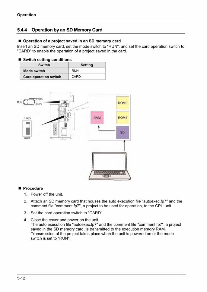
5-12
Operation
5.4.4 Operation by an SD Memory Card
Operation of a project saved in an SD memory card Insert an SD memory card, set the mode switch to "RUN", and set the card operation switch to "CARD" to enable the operation of a project saved in the card.
Switch setting conditions Switch Setting
Mode switch RUN
Card operation switch CARD
Procedure 1. Power off the unit.
2. Attach an SD memory card that houses the auto execution file "autoexec.fp7" and the comment file "comment.fp7", a project to be used for operation, to the CPU unit.
3. Set the card operation switch to "CARD".
4. Close the cover and power on the unit. The auto execution file "autoexec.fp7" and the comment file "comment.fp7", a project saved in the SD memory card, is transmitted to the execution memory RAM. Transmission of the project takes place when the unit is powered on or the mode switch is set to "RUN".
5.4 SD Memory Card Operation
5-13
Operations during SD Memory Card Operation If the following steps are taken, the unit runs in the "SD memory card operation" mode. Until the unit is powered off, it cannot be switched into RAM/ROM operation.
Example 1:
1) Power on the unit while the card operation switch is set to "ROM".
2) Set the card operation switch to "CARD".
3) Set the mode switch to "RUN".
Example 2:
1) Power on the unit while the card operation switch is set to "CARD".
2) Set the mode switch to "RUN".
KEY POINTS
The online editing functions is not usable ("protect error").

5-14
Operation
5.4.5 Transmission from an SD Memory Card to the Execution Memory
Insert an SD memory card, and set the mode switch to "COPY", in order to transmit a project saved in the SD memory card to ROM1 and write it in as an execution project.
Switch setting conditions Switch Setting
Mode switch PROG.COPY (Momentary)
Card operation switch CARD
When power is OFF 1. Attach an SD memory card that houses the auto execution file "autoexec.fp7" and the
comment file "comment.fp7" for a project to the CPU unit.
2. Close the cover and power on the unit.
3. Until "COPY LED" flashes (approx. 5 seconds), set the RUN/PROG./COPY switch to "COPY". Transmission of project data is started. Once "COPY LED" starts to flash, the transmission process continues if you let go off the COPY switch. Once transmission is completed, "COPY LED" turns off.

5.4 SD Memory Card Operation
5-15
When power is ON 1. Change to the PROG. mode.
2. Attach an SD memory card that houses the auto execution file "autoexec.fp7" and the comment file "comment.fp7" for a project to the CPU unit.
3. Close the cover.
4. Until "COPY LED" flashes (approx. 5 seconds), set the RUN/PROG./COPY switch to "COPY". Transmission of project data is started. Once "COPY LED" starts to flash, the transmission process continues if you let go off the COPY switch. Once transmission is completed, "COPY LED" turns off.
KEY POINTS
Copying of a project triggered by the COPY switch does not depend on settings for the card operation switch. Operation starts whether the switch is set to CARD or ROM.
5.4.6 Precautions Concerning SD Memory Card Operation
In an SD memory card to be used, create an "AUTO" folder, and save an auto execution file "autoexec.fp7" and a comment file "comment.fp7".
While copying, do not remove the SD memory card from the slot. It may cause damage to the project.
If the card operation switch is set to "CARD" while no SD memory card is inserted, a self-diagnosis error will result.
If the unit cannot access a project in the SD memory card while the card operation switch is set to "CARD" and SD memory card operation is in progress, a self-diagnosis error will result.

5-16
Operation
5.5 Operation When Using Expansion Master Unit/Slave Unit
5.5.1 Operation When Power Supply Turns ON/OFF
Sequence of turning ON/OFF the power supply The power supply should be turned on or off in the following sequence.
Item Sequence When turning on power
Power supply for I/O device Expansion block (Expansion slave unit) Base block (CPU unit)
When turning off power
Base block (CPU unit) Expansion block (Expansion slave unit) Power supply for I/O device
Operation when the power to the base block turns off during operation If the power supply to the base block (CPU unit) turns off during operation, the expansion
block will stop the operation. At this time, the output of the units attached to the expansion block will be turned OFF.
If the power to the base block is turned on when the power to the expansion block is on, the system will be rebooted.
Operation when the power to the expansion block turns off during operation If the power to the expansion block (expansion slave unit) turns off during operation, a self-
diagnostic error will occur and the CPU unit will stop. Other expansion blocks will also stop.
Operation will not restart even if the power to the expansion block turns on again when the CPU stops due to the error. If the power to the base block is turned on when the power to all the expansion blocks is on, the system will be rebooted.
5.5.2 Insertion and Removal of Expansion Cable
Do not insert or remove the expansion cable when the power is on.
The whole system operation will stop if the expansion cable is removed during operation. Even if the cable is inserted again during operation, the operation will not restart.

6 Troubleshooting

6-2
Troubleshooting
6.1 Self-Diagnosis Function
6.1.1 CPU Unit's Operation Monitor LED
The CPU unit has a self-diagnostic function which identifies errors and stops operation if necessary. Indications concerning self-diagnosis are as follows.
LED indications concerning self-diagnosis errors
LED indications on the CPU unit
Description Operation status RUN
Green PROG Green
ERROR Red
ALARM Red
Normal operation
● ○ ○ ○ Normal operation Operation ○ ● ○ ○ PROG. mode Stop
▲ ○ ○ ○ Forcing input/output in the RUN mode Operation
Error
● ○ ▲ ○ When a self-diagnostic error occurs (Operation) Operation
○ ● ▲ ○ When a self-diagnostic error occurs (Stop) Stop
○ ● ● System watchdog timer has been activated Stop
○ ▲ ○ Waiting for connection of the PHLS slave Stop
(Note) ●: ON, ▲: Flashing, ○: OFF, -: Varies (ON or OFF)
6.1.2 Operation at the Time of Error
Normally, when an error occurs, the operation stops.
Configuration menu of FPWIN GR7 Operation mode of the CPU unit at the time of error can be set (Continue or Stop) in the "FP7 Configuration" menu of the tool software FPWIN GR7.
CPU configuration
6.2 What to Do If an Error Occurs
6-3
6.2 What to Do If an Error Occurs
6.2.1 ERROR LED Flashes on the CPU Unit
Condition A self-diagnostic error has occurred.
Solution Confirm the status in the following procedure.
PROCEDURE 1. Select "Online" "Status Display" in FPWIN GR7, and check the error
details (error code). 2. Switch to the PROG. mode. 3. If a self-diagnosis error other than syntax error has occurred, cancel the
situation in accordance with the error code. 4. In the case of a syntax error, use the "Totally Check Project" function under
"Debug" in FPWIN GR7 to identify the syntax error.
KEY POINTS
In the case of an operation error, check the address where the error occurred before performing error clearance.
In the case of an error coded 80 or higher, the error can be cleared by pressing the [Error Clearance] button in the "Status Display" dialog box.
In the PROG. mode, the power supply can be turned off and then on again to clear the error, but all of the contents of the operation memory except hold type data are cleared.
An error can also be cleared by executing a self-diagnostic error set instruction (ERR).

6-4
Troubleshooting
6.2.2 PROG Mode Does Not Change to RUN
Condition: A syntax error or a self-diagnosis error that caused operation to stop has occurred.
Solution: Confirm the status in the following procedure.
PROCEDURE 1. Confirm that the ERROR or ALARM LED is not turned on. 2. Use the "Totally Check Project" function under "Debug" in FPWIN GR7 to
identify the syntax error.
6.2.3 ALARM LED Turns ON on the CPU Unit
Condition: The system watchdog timer has been activated and the operation of controller has been stopped.
Solution:
PROCEDURE 1. Switch the CPU unit to the PROG. mode, and turn off the power supply and
then on again. If the ALARM LED lights again, there may be a problem with the unit. If the ALARM LED goes out after the power supply is turned off and then on again, the problem may have been caused by noise or another temporary phenomenon.
2. Switch to the RUN mode. If ALARM LED turns on after switching to the RUN mode, the program is taking excessive time. Review and modify the program.
3. Check the ambient environment for influence of noise. If there is no problem with the program, there may be a problem in the ambient environment. Check the wiring including the earth wiring. In particular, check if the RS-232C wiring is not close to power cables, and if the wiring is shielded.
KEY POINTS
When the program is to be reviewed, check the following points. Example 1: Is there any infinite loop in the program, resulting from a JP instruction, LOOP instruction or other instructions that control the program flow? Example 2: Are there multiple interrupt instructions that are being consecutively executed?

6.2 What to Do If an Error Occurs
6-5
6.2.4 POWER LED Does Not Turn ON on the Power Supply Unit
Condition: It is possible that sufficient power is not supplied.
Solution: Confirm the status in the following procedure.
PROCEDURE 1. Power off the unit and double-check the wiring status (e.g. Is there any
loose terminal?) 2. Check if output of the power supply unit exceeds the rating.
If capacity of the internal power supply (24V) does not suffice, examine changing combination of the units.
3. Disconnect the power supply wiring to the other devices if the power supplied to the unit is shared with them. If LED on the power supply unit turns on following the above step, undercapacity of power supply is possible. Review the power supply design.
6.2.5 A Protect Error Message Appears
Condition: It is possible that the project is password locked.
Solution: Confirm the status in the following procedure.
PROCEDURE 1. Select "Tools" "Register/Delete Password" in FPWIN GR7.
The “Register/Delete Password” dialog box is displayed.
2. Enter a password and press the [OK] button. The protection is canceled.
KEY POINTS
If you press the [Forced Cancellation] button, all projects saved in PLC are deleted.

6-6
Troubleshooting
6.2.6 If Expected Output Is Not Available
Condition: Both software reasons (e.g. program, I/O allocation) and hardware reasons (e.g. wiring, power supply) are possible.
Solution (check of the output side) Proceed from the check of the output side to the check of the input side.
PROCEDURE 1. Check if output indication LED on the input/output units is on.
If it is on, proceed to the next step. If it is not, proceed to Step 4.
2. Check the wiring of the load (e.g. Is there any loose terminal?) If LED on the unit turns on following the above step, undercapacity of power supply is possible. Review the power supply design.
3. Check if the power is properly supplied to both ends of the load. If the power is properly supplied to the load, there is probably an abnormality in the load. If the power is not supplied to the load, there is probably an abnormality in the output section.
4. Monitor the output status using the tool software FPWIN GR7. If the output monitored is turned on, there is probably a duplicated output error, etc.
5. Forcibly turn on and off the relevant output using the forced input/output functions of the tool software FPWIN GR7. If the output indicator LED of the units is turned on, go to input condition check. If the output indicator LED remains off, there is probably an abnormality in the unit's output part.
Solution (check of the input side) Clarify the situation in the following procedure.
PROCEDURE 1. Check whether the input indication LED on the unit is ON.
If it is OFF, proceed to the next step. If it is, proceed to Step 4.
2. Check the wiring of the input device (e.g. Is there any loose terminal?) If LED on the unit turns on following the above step, undercapacity of power supply is possible. Review the power supply design.
3. Check that the power is properly supplied to the input terminals. If the power is properly supplied to the input terminals, there is probably an abnormality in the unit's input part. If the power is not supplied to the input

6.2 What to Do If an Error Occurs
6-7
terminal, there is probably an abnormality in the power supply or the input device.
4. Monitor the input status using the tool software FPWIN GR7. If the input monitored is off, there is probably an abnormality with the unit's input part. Modify the program if the input monitored is on. If the input device is a two-wire sensor, influence of leaked current is possible.
KEY POINTS
When the program is to be reviewed, check the following points.
1. Check if output specifications are rewritten (e.g. duplicated output use)
2. Check if the program flow has been changed due to an MCR instruction, JMP instruction or other control instructions.
3. Check if the I/O map allocation agrees with the actual mount status.
6.2.7 ERR LED Turns ON on the Expansion Unit
Condition There is probably an error in the power supply system of the expansion block in which the expansion slave unit with the ERROR LED lit is attached or another expansion block connected to the subsequent stage, or an error in a unit in the expansion block.
Solution Clarify the situation in the following procedure.
PROCEDURE 1. Check if the power supplies to all the expansion blocks registered in the I/O
map are ON. 2. Check the wiring conditions of expansion cables and power supplies. 3. Check if the end unit is connected at the end of the expansion block. 4. Check if an error occurs in a unit in the expansion block.
If a unit error occurs, refer to the manual of each unit and find the cause of the error.
5. Clear the self-diagnostic error of the CPU unit. 6. Turn on the power to the expansion units first, and then turn on the power
to the CPU unit.
6-8
Troubleshooting
KEY POINTS
The expansion unit startup wait time can be set in the I/O map dialog box. The settable range is 5 to 1800 seconds (30 minutes). The default is 5 seconds.
A self-diagnostic error (Error code 6: Expansion unit power supply synchronization error) will occur if the power to the expansion block does not turn on after the startup wait time passed since the power to the CPU unit has turned on. Check the power supply sequence.
When more than one expansion block is used, the ERROR LED, on the expansion slave units in the expansion block of the next stage connected to the expansion block to which the power supply is off, does not turn on.

7 Maintenance and Inspection

7-2
Maintenance and Inspection
7.1 Handling of Backup Battery
7.1.1 Functions of Backup Battery
When the calendar timer function is to be used, attach the separately sold backup battery.
Never use batteries other than AFPX-BATT. It may lead to ignition and rupture of batteries.
Area backed up by the backup battery Calendar timer data
Types of Backup Battery (separately sold) Appearance Product name Description Product no.
Backup battery With a connector for CPS4*/CPS3* AFPX-BATT
KEY POINTS
The backup battery is for CPS4*/CPS3 series. It cannot be attached to CPS21. The calendar timer can continue the operation for about one week for CPS4*/CPS3 and about two weeks for CPS21 by the built-in capacitor, even if no battery is used.
In order to charge the built-in capacitor, supply power to the CPU unit for at least 30 minutes.

7.1 Handling of Backup Battery
7-3
7.1.2 Replacement of Backup Battery
FP7 CPU unit's backup battery can be replaced while power is on. Replace the backup battery in the following procedure.
Procedure 1. Open the SD memory card cover on
the surface of the CPU unit.
2. Remove the battery connector.
3. While extending the lever to outside, take out the backup battery from the battery holder.
4. While extending the lever to outside, attach a new backup battery to the battery holder.
5. Connect to a power supply connector
6. Close the card cover.
KEY POINTS
For the FP7 CPU unit, the battery can be replaced while power is on. If the battery is to be replaced while power is off, undertake replacement within 10 minutes from powering off, after supplying power for at least 5 minutes, in order to charge the built-in capacitor. If the built-in capacitor has not been sufficiently charged, calendar timer data may become indefinite. Make sure that the battery connector cable is not pinched by the card cover.

7-4
Maintenance and Inspection
NOTES
Do not apply an excessive force to the card cover when opening or closing
it or when the cover is left open. Otherwise, the cover attachment part will be deformed to cause malfunction in the cover recognition switch mounted inside the product.
7.1.3 Lifetime and Replacement Interval of Backup Battery
Lifetime of backup battery Lifetime of backup battery Suggested replacement interval
3.3 years or more 5 years (Note 1) The lifetime indicated above is the value when no power at all is supplied. (Note 2) Note that the lifetime in actual use may be shorter than the indicated value depending on the use conditions. (Note 3) Backup battery is consumed for the backup battery detection circuit, even while power is being supplied. Lifetime while power is being supplied is approx. two times longer than the value when no power is supplied.
Detection of errors and replacement interval of backup battery When voltage of the backup battery declines, the system relays (SR24 and SR25) are turned
on. As necessary, create a program for reporting the error to outside.
If the system register's "Report Battery Error" setting is turned valid, the CPU ERROR LED on the CPU unit flashes.
Promptly replace the battery, though data are retained for about one week from the detection of a backup battery error, even if no power at all is supplied.
NOTES
The retained memory data may become indefinite after one week has
passed with no power supplied, from the time when the system relays (SR24 and SR25) turned on or when the ERROR LED on the CPU unit flashed.
The system relays (SR24 and SR25) turn on when a backup battery error is detected, regardless of settings in the CPU's configuration.
Regardless of time passed from detection of a backup battery error, supply power to the CPU unit for at least 5 minutes before replacing the backup battery.
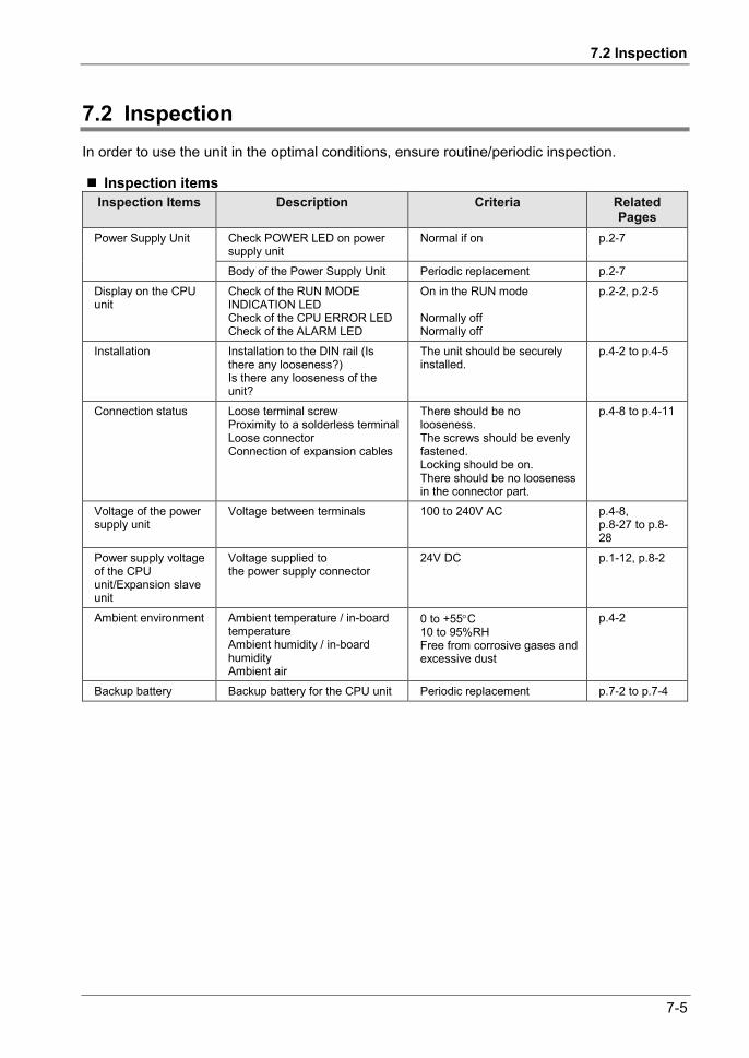
7.2 Inspection
7-5
7.2 Inspection In order to use the unit in the optimal conditions, ensure routine/periodic inspection.
Inspection items Inspection Items Description Criteria Related
Pages Power Supply Unit Check POWER LED on power
supply unit Normal if on p.2-7
Body of the Power Supply Unit Periodic replacement p.2-7
Display on the CPU unit
Check of the RUN MODE INDICATION LED Check of the CPU ERROR LED Check of the ALARM LED
On in the RUN mode Normally off Normally off
p.2-2, p.2-5
Installation Installation to the DIN rail (Is there any looseness?) Is there any looseness of the unit?
The unit should be securely installed.
p.4-2 to p.4-5
Connection status Loose terminal screw Proximity to a solderless terminal Loose connector Connection of expansion cables
There should be no looseness. The screws should be evenly fastened. Locking should be on. There should be no looseness in the connector part.
p.4-8 to p.4-11
Voltage of the power supply unit
Voltage between terminals 100 to 240V AC p.4-8, p.8-27 to p.8-28
Power supply voltage of the CPU unit/Expansion slave unit
Voltage supplied to the power supply connector
24V DC p.1-12, p.8-2
Ambient environment Ambient temperature / in-board temperature Ambient humidity / in-board humidity Ambient air
0 to +55C 10 to 95%RH Free from corrosive gases and excessive dust
p.4-2
Backup battery Backup battery for the CPU unit Periodic replacement p.7-2 to p.7-4

7-6
Maintenance and Inspection

8 Specifications

8-2
Specifications
8.1 CPU Unit Specifications
8.1.1 General Specifications
Items Description Rated voltage 24V DC
Operating voltage range 20.4 to 28.8V DC (Note 1)
Momentary power off time When the CPU unit only (DC) is used 4 ms (20.4 V is used) , 7 ms (24 V is used) , 10 ms (28.8 V is used) (Note 2)
Allowable maximum current Max. 2.0 A at 0 to 55 C, Max. 3.0 A at 0 to 50 C (Note 5)
Operating ambient temperature 0 to +55C (Note 5)
Storage ambient temperature -40 to +70C
Operating ambient humidity 10 to 95%RH (at 25C, no-condensing)
Storage ambient humidity 10 to 95%RH (at 25C, no-condensing)
Breakdown voltage (Note 3)
All of the COM port, USB and LAN port - All of the power supply terminals and functional earths All of the expansion bus connectors - All of the power supply terminals and functional earths
500V AC, 1 minute
Insulation resistance (Note 4)
All of the COM port, USB and LAN port - All of the power supply terminals and functional earths All of the expansion bus connectors - All of the power supply terminals and functional earths
100 M or larger
Vibration resistance
Based on JIS B 3502 and IEC 61131-2: 5 to 8.4 Hz, half amplitude 3.5 mm 8.4 to 150 Hz, constant acceleration 9.8 m/s2 X, Y and Z axes, 10 minutes, 10 sweeps (1 octave/mm)
Shock resistance Based on JIS B 3502 and IEC 61131-2 147 m/s2, X, Y and Z axes, 3 times
Noise resistance 1,000 V[P-P] with pulse widths 50 ns and 1 µs (using a noise simulator) (power supply terminals)
Environment Free from corrosive gases and excessive dust.
EU Directive applicable standard EMC Directive: EN 61131-2, Low-Voltage Directive: EN 61131-2
Overvoltage category Category II or lower
Pollution degree Pollution degree 2
(Note 1) When a programmable display GT series is connected to the GT power supply terminal (24V) of the CPU unit (CPS4*/CPS3*), use it within the range of 21.6 to 26.4 V DC.
(Note 2) 10 ms when an AC power supply unit (AFP7PSA1/AFP7PAS2) is used (Note 3) Cutoff current: 50 mA (Note 4) With 500 V DC megohmmeter (Note 5) For details of the current consumption of a system, refer to 1.4 Selection of Power Supply and Restrictions
on Combination.
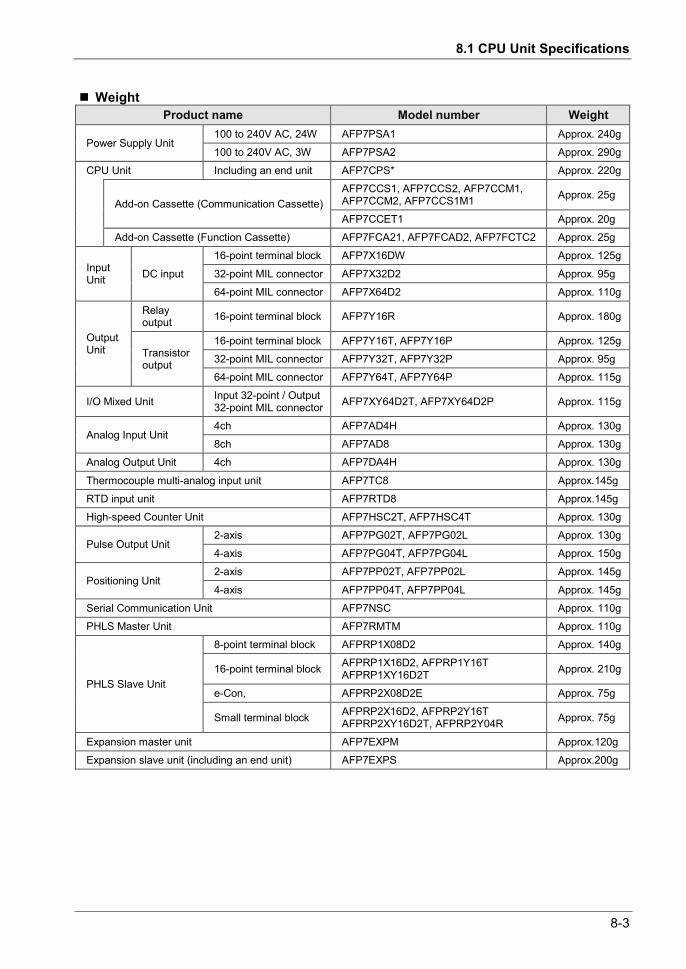
8.1 CPU Unit Specifications
8-3
Weight Product name Model number Weight
Power Supply Unit 100 to 240V AC, 24W AFP7PSA1 Approx. 240g 100 to 240V AC, 3W AFP7PSA2 Approx. 290g
CPU Unit Including an end unit AFP7CPS* Approx. 220g
Add-on Cassette (Communication Cassette) AFP7CCS1, AFP7CCS2, AFP7CCM1, AFP7CCM2, AFP7CCS1M1 Approx. 25g
AFP7CCET1 Approx. 20g Add-on Cassette (Function Cassette) AFP7FCA21, AFP7FCAD2, AFP7FCTC2 Approx. 25g
Input Unit DC input
16-point terminal block AFP7X16DW Approx. 125g
32-point MIL connector AFP7X32D2 Approx. 95g 64-point MIL connector AFP7X64D2 Approx. 110g
Output Unit
Relay output 16-point terminal block AFP7Y16R Approx. 180g
Transistor output
16-point terminal block AFP7Y16T, AFP7Y16P Approx. 125g 32-point MIL connector AFP7Y32T, AFP7Y32P Approx. 95g 64-point MIL connector AFP7Y64T, AFP7Y64P Approx. 115g
I/O Mixed Unit Input 32-point / Output 32-point MIL connector AFP7XY64D2T, AFP7XY64D2P Approx. 115g
Analog Input Unit 4ch AFP7AD4H Approx. 130g 8ch AFP7AD8 Approx. 130g
Analog Output Unit 4ch AFP7DA4H Approx. 130g
Thermocouple multi-analog input unit AFP7TC8 Approx.145g RTD input unit AFP7RTD8 Approx.145g High-speed Counter Unit AFP7HSC2T, AFP7HSC4T Approx. 130g
Pulse Output Unit 2-axis AFP7PG02T, AFP7PG02L Approx. 130g 4-axis AFP7PG04T, AFP7PG04L Approx. 150g
Positioning Unit 2-axis AFP7PP02T, AFP7PP02L Approx. 145g
4-axis AFP7PP04T, AFP7PP04L Approx. 145g Serial Communication Unit AFP7NSC Approx. 110g PHLS Master Unit AFP7RMTM Approx. 110g
PHLS Slave Unit
8-point terminal block AFPRP1X08D2 Approx. 140g
16-point terminal block AFPRP1X16D2, AFPRP1Y16T AFPRP1XY16D2T Approx. 210g
e-Con, AFPRP2X08D2E Approx. 75g
Small terminal block AFPRP2X16D2, AFPRP2Y16T AFPRP2XY16D2T, AFPRP2Y04R Approx. 75g
Expansion master unit AFP7EXPM Approx.120g Expansion slave unit (including an end unit) AFP7EXPS Approx.200g

8-4
Specifications
8.1.2 Performance Specifications
Items Description Program method Relay symbol method
Control method Cyclic operation method
Controllable I/O points
Basic configuration (1 block) Max. 1,024 points (When using 64 points x 16 slots)
When the PHLS remote I/O system is used Max. 16,128 points (1,008 points x 16 slots)
Program memory
Built-in memory Execution project saving memory (RAM and ROM1) : Non-volatile memory Backup project saving memory (ROM2) : Non-volatile memory
Memory capacity (Note 1)
Max. program blocks (Note 1)
Comment memory Memory capacity 3 M bytes (all comments including I/O comments, note comments,
and block comments)
Operation speed (Basic instruction/step) CPS4*/CPS3*: From 11ns, CPS21: From 14ns
Basic instructions Approx. 100 types
High-level instructions Approx. 206 types
Ope
ratio
n m
emor
y
1-bit device
External inputs (X) 8,192 points (X0 to X511F) (Note 2) (Note 3)
External outputs (Y) 8,192 points (Y0 to Y511F) (Note 2) (Note 3)
Internal relays (R) 32,768 points (R0 to R2047F) (Note 3)
Link relays (L) 16,384 points (L0 to L1023F) (Note 3)
Timers (T) 4,096 points (T0 to T4095) (Note 3) Can count up to (Unit: 10us,1ms,10ms,100ms,1s) × 4,294,967,295
Counters (C) 1,024 points (C0 to C1023) (Note3) Can count up to 1 to 4,294,967,295
System relays (R) 1120 points (approx. 70 words)
Pulse relays (P) 4,096 points (P0 to P255F) (Note 3)
Error alarm relays (E) 4,096 points (E0 to E4095) (Note 3)
Direct input (IN) Allocate input numbers to each slot (IN0 to IN62F) (Note 3) (Note 4)
Direct output (OT) Allocate output numbers to each slot (OT0 to OT62F) (Note 3) (Note 4)
16-bit device
Data register (DT) (Note 1) (Note 3)
Link data register (LD) 16,384 words (LD0 to LD16383) (Note 3) Max. 512 K words per unit (Note 4) Unit memory (UM)
System data register (SD) 110 words
32-bit device
Index register 15 double words (I0 to IE) (with a switching function) (Note 3)
Timer set value register (TS) 4,096 double words (TS0 to TS4095) (Note 3)
Timer elapsed value register (TE) 4,096 double words (TE0 to TE4095) (Note 3
Counter set value register (CS) 1,024 double words (CS0 to CS1023) (Note 3)
Timer/counter elapsed value register (CE) 1,024 double words (CE0 to CE1023) (Note 3)

8.1 CPU Unit Specifications
8-5
Items Description Master control relay (MCR) No limits (no numbers)
Labels (JMP, LOOP) Max. 65,535 points per PB
Differential points (DF, DFI) Depending on the program capacity
No. of step ladders No restriction
No. of subroutines Max. 65,535 points per PB
Interrupt program
Fixed cycle execution type PB: 1 PB/per project Execution interval unit: 0.1 ms or 1 ms
Interrupt from High-speed counter unit Max. 8 points per unit, Max. 8 units per project
Constant scan 0.5 to 125 ms
Memory backup for power failure Built-in non-volatile memory backs up the project (program, comments and configuration data) and operation memory. (Excluding calendar timer)
Calendar timer Yes (a separately sold backup battery is required) (Note 5)
Self-diagnosis function Watchdog timer, program syntax check
Rewriting during RUN function Yes (rewriting on a PB basis, no limit to the number of rewriting steps)
Security function Password function, no-read settings, encryption can be set for the program, comments and configuration data
(Note 1) The program capacity, data register capacity and maximum number of program blocks (PBs) vary according to the type of CPU and memory configuration settings. They are set from the configuration menu of tool software FPWIN GR7. The default values are pattern 3 for CPS4 and pattern 1 for CPS3 and CPS21.
Unit type Memory type Memory select pattern
1 2 3 4 5
CPS4*
Program capacity (step) 234,000 221,500 196,000 144,500 51,500 Data register capacity (word) 65,536 131,072 262,144 524,288 999,424
Maximum number of PBs 468 443 392 289 103
CPS3*
Program capacity (step) 121,500 96,000 64,000 32,000 Data register capacity (word) 131,072 262,144 425,984 589,824
Maximum number of PBs 243 192 128 64
CPS21
Program capacity (step) 64,000 32,000 Data register capacity (word) 131,072 262,144
Maximum number of PBs 128 64 (Note 2) Figures in the table indicate the number of devices that can be used in the program. The actual inputs and
outputs that can be used vary by configuration. (Note 3) Operation devices are categorized into "hold type", which memorizes the status immediately before power
failure or switch to the PROG. mode, and "non-hold type", which resets such status. Internal relays, data registers, link relays and link registers can be set as non-hold type or hold type by the tool software. Counters and error alarm relays are hold type. Other operation memories are non-hold type. However, data registers (DT) that can be used as hold type are a maximum of 262,144 words (DT0 to DT262143) for CPS4*/CPS3*, and a maximum of 131,072 words (DT0 to DT131071) for CPS21.
(Note 4) Direct inputs (IN), direct outputs (OT), and unit memories (UM) are used by specifying unit slot numbers and memory addresses to be controlled by instructions.
(Note 5) CPS4* and CPS3* can be used by attaching an optional battery. Precision of the calendar timer (real-time clock): Difference less than 95 seconds per month (0 C), less than 15 seconds per month (+25 C), less than 130 seconds per month (+55 C). When the unit is connected to ET-LAN, the time is synchronized by the SNTP function. Battery lifetime: 3.3 years or more, suggested replacement interval: 5 years. After power is supplied to the CPU unit for 30 minutes or longer, it can be activated by the internal capacitor even without a battery. For CPS4*/CPS3*, approx. one week. For CPS21, approx. two weeks.

8-6
Specifications
8.1.3 CPU Unit Communication Specifications
USB port (for tool software) Items Description
Standard USB2.0 FULL SPEED
Communication function MEWTOCOL-COM (slave), MEWTOCOL7-COM (slave)
(Note) The USB port is insulated from the internal circuit.
COM0 port Items Description
Interface 3-wire 1-channel RS232C
Transmission distance 15 m
Baud rate 300, 600, 1,200, 2,400, 4,800, 9,600, 19,200, 38,400, 57,600, 115,200 bit/s
Communication method Half-duplex transmission
Synchronous method Start stop synchronous system
Communication format
Data length: 7 bit / 8 bits Parity: Yes / No (Odd / Even) Start code: Without STX / With STX End code: CR / CR + LF / None / ETX Stop bit: 1 bit / 2 bits
Data transmission order Transmits from bit 0 character by character.
Communication function
MEWTOCOL-COM (master/slave), MEWTOCOL7-COM (slave) MODBUS RTU (master/slave) general-purpose communication modem initialization
(Note 1) Baud rate, transmission format, and applications of communication should be set using the tool software. (Note 2) When communication is performed at a baud rate of 38,400 bps or higher, use the cable not longer than 3 m.
For wiring the RS232C, a shielded wire must be used to increase noise suppression. (Note 3) When connecting a commercially available device, please confirm operation using the actual device. (Note 4) Each SD, RD and SG terminal of the RS-232C port is insulated from the internal circuit.
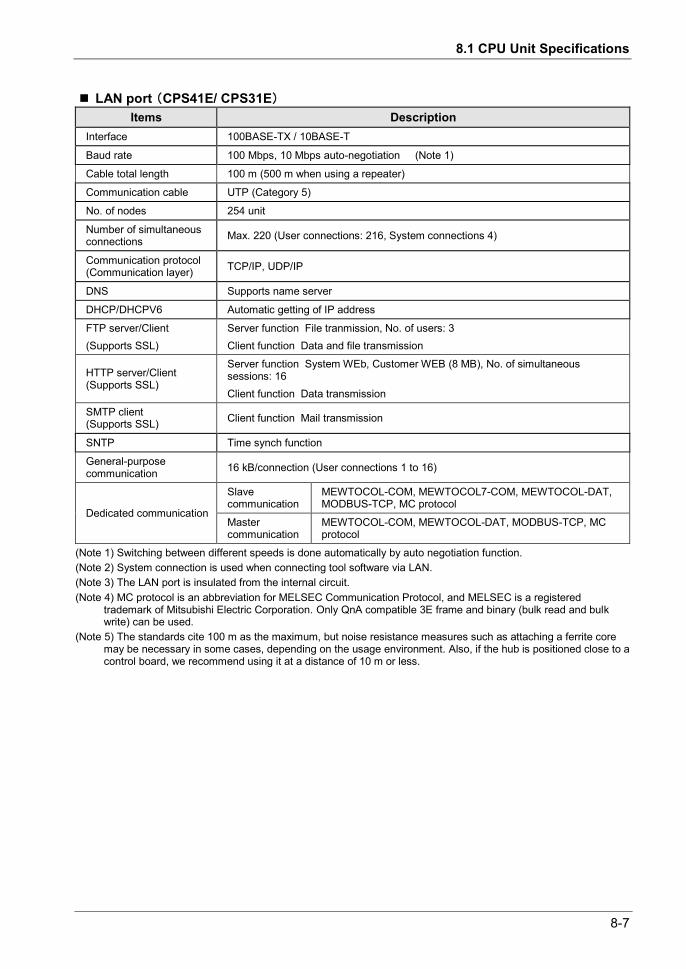
8.1 CPU Unit Specifications
8-7
LAN port (CPS41E/ CPS31E) Items Description
Interface 100BASE-TX / 10BASE-T
Baud rate 100 Mbps, 10 Mbps auto-negotiation (Note 1)
Cable total length 100 m (500 m when using a repeater)
Communication cable UTP (Category 5)
No. of nodes 254 unit
Number of simultaneous connections Max. 220 (User connections: 216, System connections 4)
Communication protocol (Communication layer) TCP/IP, UDP/IP
DNS Supports name server
DHCP/DHCPV6 Automatic getting of IP address
FTP server/Client (Supports SSL)
Server function File tranmission, No. of users: 3 Client function Data and file transmission
HTTP server/Client (Supports SSL)
Server function System WEb, Customer WEB (8 MB), No. of simultaneous sessions: 16 Client function Data transmission
SMTP client (Supports SSL) Client function Mail transmission
SNTP Time synch function
General-purpose communication 16 kB/connection (User connections 1 to 16)
Dedicated communication
Slave communication
MEWTOCOL-COM, MEWTOCOL7-COM, MEWTOCOL-DAT, MODBUS-TCP, MC protocol
Master communication
MEWTOCOL-COM, MEWTOCOL-DAT, MODBUS-TCP, MC protocol
(Note 1) Switching between different speeds is done automatically by auto negotiation function. (Note 2) System connection is used when connecting tool software via LAN. (Note 3) The LAN port is insulated from the internal circuit. (Note 4) MC protocol is an abbreviation for MELSEC Communication Protocol, and MELSEC is a registered
trademark of Mitsubishi Electric Corporation. Only QnA compatible 3E frame and binary (bulk read and bulk write) can be used.
(Note 5) The standards cite 100 m as the maximum, but noise resistance measures such as attaching a ferrite core may be necessary in some cases, depending on the usage environment. Also, if the hub is positioned close to a control board, we recommend using it at a distance of 10 m or less.

8-8
Specifications
8.1.4 Operation Memory Area
Name Usable devices and ranges Functions
1-bi
t dev
ice
External input X 8,192 points (X0 to X511F) (Note 1) Turns on or off based on external input. External output Y 8,192 points (Y0 to Y511F) (Note 1) Externally outputs on or off state.
Internal relay R 32,768 points (R0 to R2047F) (Note 2) Relay which turns on or off only within program.
Link relay L 16,384 points (L0 to L1023F) (Note 2) This relay is a shared relay used for PLC link.
Timer T 4,096 points (T0 to T4095) (Note 2) This goes on when the timer reaches the specified time.
Counter C 1,024 points(C0 to C1023) (Note 2) This goes on when the timer increments.
System relay SR Approx. 1120 points (approx. 70 words)
Relay which turns on or off based on specific conditions and is used as a flag.
Pulse relay P 4,096 points (P0 to P255F) This relay only turns on during one scan at the start of the execution condition.
Error alarm relay E 4,096 points (E0 to E4095)
This relay ensures that error conditions that are freely allocated by the user are memorized in the memory.
Direct input IN Can allocate input numbers to each slot (IN0 to IN62F) (Note 3) This relay is for input/output processing
during operation, without depending on usual I/O refresh. Direct output OT Can allocate output numbers to each
slot (OT0 to OT62F) (Note 3)
16-b
it de
vice
External input (Note1) WX WX0 to WX511 (Note 1) Code for specifying 16 external input
points as one word (16 bits) of data. External output (Note1) WY WY0 to WY511 (Note 1) Code for specifying 16 external output
points as one word (16 bits) of data.
Internal relay WR WR0 to WR2047 (Note 2) Code for specifying 16 internal relay points as one word (16 bits) of data.
Link relay WL WL0 to WL1023 Code for specifying 16 link relay points as one word (16 bits) of data.
Data register DT Max. DT 999424 words (DT0 – DT999423) (Note 2) (Note 4)
Data memory used in program. Data is handled in 16-bit units (one word).
Link register LD 16,384 words (LD0 to LD16383) (Note 2)
This is a shared data memory which is used within the PLC link. Data is handled in 16-bit units (one word).
Unit memory UM Max. 512K words per unit (Note 3) This device is for accessing the unit memory of intelligent units. Its size varies by unit, and is allocated by default.
System data register SD Approx. 110 words
Data memory for storing specific data. Various settings and error codes are stored.

8.1 CPU Unit Specifications
8-9
Name Usable devices and ranges Functions
32-b
it de
vice
Index register I 15 double words (I0 to IE) (with a switching function)
Register can be used as an address of memory area and constants modifier.
Timer set value area TS 4,096 double words
(TS0 to TS4095) (Note 2) Data memory for storing timer target data. It corresponds to the timer number.
Timer elapsed value area TE 4,096 double words
(TE0 to TE4095) (Note 2) Data memory for storing timer elapsed value. It corresponds to the timer number.
Counter set value area CS 4,096 double words
(CS0 to CS4095) (Note 2) Data memory for storing counter set value. It corresponds to the counter number.
Counter elapsed value area CE 4,096 double words
(CE0 to CE4095) (Note 2) Data memory for storing the elapsed value during operation of a counter. It corresponds to the timer number.
Con
stan
t
Signed decimal constants K
K-32768 to K32767 (for 16-bit operation) K-2147483648 to K2147483647 (for 32-bit operation)
Unsigned decimal constants U
U 0 to U65535 (for 16-bit operation) U 0 to U4294967295 (for 32-bit operation)
Hexadecimal constants H
H0 to HFFFF (for 16-bit operation) H0 to HFFFFFFFF (for 32-bit operation)
Single precision floating point number (real number)
SF SF-1.175494 × 10-38 to SF-3.402823 × 1038
SF-1.175494×10-38 to SF-3.402823×1038
Double precision floating point number (real number)
DF DF-2.2250738585072014 × 10-308 to DF-1.7976931348623158 × 10308
DF 2.2250738585072014 × 10-308 to DF 1.7976931348623158 × 10308
(Note 1) Figures in the table indicate the number of devices that can be used in the program. The actual inputs and outputs that can be used vary by configuration.
(Note 2) Operation devices are categorized into "hold type", which memorizes the status immediately before power failure or switch to the PROG. mode, and "non-hold type", which resets such status. Non-hold area is cleared to zero when the unit is powered on or the mode is switched between PROG and RUN.
Types of operation devices Hold or Non-hold Internal relays (R), Data registers (DT), Link relays (L), Link registers (LD)
Can be set as non-hold type or hold type by the tool software.
Counters (C), Counter set values (CS), Counter elapsed values (CE), Error alarm relays (E) Hold type
Inputs (X), Outputs (Y), Timers (T), Timer set values (TS), Timer elapsed values (TE), Pulse relays (P), Direct inputs (IN), Direct outputs (OT), Index registers (I), Unit memories (UM), System data registers (SD)
Non-hold type
(Note 3) Direct inputs (IN), direct outputs (OT), and unit memories (UM) are used by specifying unit slot numbers and memory addresses to be controlled by instructions.
(Note 4) The number of usable data registers (DT) varies according to the type of CPU and memory configuration settings. However, data registers (DT) that can be used as hold type are a maximum of 262,144 words (DT0 to DT262143) for CPS4*/CPS3*, and a maximum of 131,072 words (DT0 to DT131071) for CPS21.
Unit type Memory type Memory select pattern
1 2 3 4 5 CPS4* Data register capacity (word) 65,536 131,072 262,144 524,288 999,424
CPS3* Data register capacity (word) 131,072 262,144 425,985 589,824
CPS21 Data register capacity (word) 131,072 262,144

8-10
Specifications
8.1.5 List of System Relays
WS0 Device number Name Description
SR0 Self-diagnostic error flag Turns on when a self-diagnosis error occurs. Self-diagnosis error codes are saved in the system data register SD0.
SR1 Unit alarm occurrence Turns on when a unit alarm is detected. The slot number of the unit where an alarm has occurred is saved in the system data register SD1.
SR2 Unit error occurrence Turns on when a unit error is detected. The slot number of the unit where an error has occurred is saved in the system data register SD2.
SR3 Unit warning occurrence Turns on when a unit warning is detected. The slot number of the unit where a warning has occurred is saved in the system data register SD3.
SR4 Unit verification error occurrence
Turns on when an I/O verification error is detected. The slot number of the unit where an I/O verification error has occurred is saved in the system data register SD4.
SR5 Unit installation error detection
Turns on when a unit installation error is detected. The slot number of the unit where an I/O verification error has occurred is saved in the system data register SD5.
SR6 (Not used)
SR7 Operation error flag (hold type)
Turns on when an operation error occurs after the unit has started operating, and remains on while the unit operation continues. The PB number where an error has occurred is saved in the system data SD7, and the address is saved in system data registers SD8 to SD9. It indicates the first operation error that has occurred.
SR8 Operation error flag (latest type)
Turns on every time an operation error occurs. The PB number where an operation error has occurred is saved in the system data register SD10, and the address is saved in system data registers SD11 to SD12. Every time a new error occurs, the data are updated. It does not turn off even if the instruction is normally completed after the occurrence of the error(s). In order to check if any error has occurred in a specific instruction, either see address data saved in the SD, or clear error flags using ERR instruction immediately before the specific instruction, and check flags immediately after executing the instruction.
SR9 Carry flag (CY flag)
Used in shift instruction and rotate instruction with a carry flag. The flag can also be operated in carry set instruction and carry reset instruction. It is not set in overflow or underflow of operation results. Turns on when an error occurs during the execution of Ethernet communication instruction. The error code is stored in the system data register SD29.
SRA > flag Executes comparison instruction, and turns on if the result is larger.
SRB = flag Executes comparison instruction, and turns on if the result is equal. Executes operation instruction, and turns on if the result is '0'.
SRC < flag Executes comparison instruction, and turns on if the result is smaller.
SRD Support timer instruction flag
Turns on after support timer instruction (SPTM) is executed and subsequently specified time has passed. Turns off when execution conditions go off.
SRE All error alarms relay Turns on when any of the error alarm relays E0 to E4095 turns on. Turns off once all of the error alarm relays go off.

8.1 CPU Unit Specifications
8-11
SRF Constant scan error
flag Turns on if scan time exceeds the setting during constant scan. It also turns on if '0' is set in FP7 configuration.
WS1
Device number Name Description
SR10 Normally-on relay Is normally on.
SR11 Normally-off relay Is normally off.
SR12 Scan relay Turns on or off in each scan.
SR13 Initial pulse relay (ON) Goes on for only the first scan after operation (RUN) has been started, and goes off for the second and subsequent scans.
SR14 Initial pulse relay (OFF) Goes off for only the first scan after operation (RUN) has been started, and goes on for the second and subsequent scans.
SR15 Stepladder Initial pulse relay (ON)
Turns on in the first scan only, following startup of any single process, during stepladder control.
SR16 PB initial relay (ON) Turns on at the start of execution of a program block. Turns off in the next scan.
SR17 PB initial relay (OFF) Turns off at the start of execution of a program block. Turns on in the next scan.
SR18 0.01-second clock pulse relay Clock pulse with a 0.01-second cycle
SR19 0.02-second clock pulse relay Clock pulse with a 0.02-second cycle
SR1A 0.1-second clock pulse relay Clock pulse with a 0.1-second cycle
SR1B 0.2-second clock pulse relay Clock pulse with a 0.2-second cycle
SR1C 1-second clock pulse relay Clock pulse with a 1-second cycle
SR1D 2-second clock pulse relay Clock pulse with a 2-second cycle
SR1E 1-minute clock pulse relay Clock pulse with a 1-minute cycle
SR1F Not used
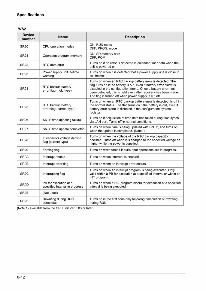
8-12
Specifications
WS2 Device number Name Description
SR20 CPU operation modes ON: RUN mode OFF: PROG. mode
SR21 Operation program memory ON: SD memory card OFF: ROM
SR22 RTC data error Turns on if an error is detected in calendar timer data when the unit is powered on.
SR23 Power supply unit lifetime warning
Turns on when it is detected that a power supply unit is close to its lifetime.
SR24 RTC backup battery error flag (hold type)
Turns on when an RTC backup battery error is detected. The flag turns on if the battery is out, even if battery error alarm is disabled in the configuration menu. Once a battery error has been detected, this is held even after recovery has been made. The flag is turned off when power supply is cut off.
SR25 RTC backup battery error flag (current type)
Turns on when an RTC backup battery error is detected. Is off in the normal status. The flag turns on if the battery is out, even if battery error alarm is disabled in the configuration system register.
SR26 SNTP time updating failure Turns on if acquisition of time data has failed during time synch via LAN port. Turns off in normal conditions.
SR27 SNTP time update completed Turns off when time is being updated with SNTP, and turns on when the update is completed. (Note1)
SR28 G capacitor voltage decline flag (current type)
Turns on when the voltage of the RTC backup capacitor declines. Turns off when it is charged to the specified voltage or higher while the power is supplied.
SR29 Forcing flag Turns on while forced input/output operations are in progress.
SR2A Interrupt enable Turns on when interrupt is enabled.
SR2B Interrupt error flag Turns on when an interrupt error occurs.
SR2C Interrupting flag Turns on when an interrupt program is being executed. Only valid within a PB for execution at a specified interval or within an INT program.
SR2D PB for execution at a specified interval in progress
Turns on when a PB (program block) for execution at a specified interval is being executed.
SR2E (Not used)
SR2F Rewriting during RUN completed
Turns on in the first scan only following completion of rewriting during RUN.
(Note 1) Available from the CPU unit Ver.3.03 or later.

8.1 CPU Unit Specifications
8-13
WS3 Device number Name Description
SR30 SD slot cover status flag ON: Cover open OFF: Cover closed
SR31 SD memory card attachment flag
ON: With an SD memory card OFF: Without an SD memory card
SR32 SD memory card recognition completed flag
ON: Completed recognition of an SD memory card OFF: Other than the above
SR33 SD memory card recognition result flag
ON: Error OFF: Normal
SR34 SD memory card write protection flag
ON: Protected OFF: Not protected
SR35 SD memory card type ON: SD OFF: SDHC
SR36 SD memory card file system ON: FAT16 OFF: FAT32
SR37 Logging into FTP server Turns on while logging in.
SR38 Logging trace execution ON: Being executed OFF: Stops
SR39 Logging trace start ON: Starts OFF: Stops
SR3A SD card access instruction execution
This relay is used to check whether other SD card access instructions are executed or not. ON: Being executed OFF: Stops
SR3B SD card access instruction completed
This relay is used to check the completion of SD card access instruction with the change of this flag (ON to OFF), and used to turn off the trigger of the instruction. ON: Completed OFF: Being executed
SR3C SD card access instruction execution result
The execution result of SD card access instruction is stored. Error codes are stored in system data register SD30. ON: Error OFF: Normal
SR3D - SR3E (Not used)
SR3F Powered off while accessing SD memory card
Turns on if the CPU unit is powered off while accessing an SD memory card.
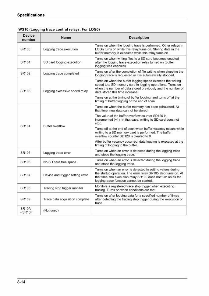
8-14
Specifications
WS10 (Logging trace control relays: For LOG0) Device number Name Description
SR100 Logging trace execution Turns on when the logging trace is performed. Other relays in LOGn turns off while this relay turns on. Storing data in the buffer memory is executed while this relay turns on.
SR101 SD card logging execution Turns on when writing files to a SD card becomes enabled after the logging trace execution relay turned on (buffer logging was enabled).
SR102 Logging trace completed Turns on after the completion of file writing when stopping the logging trace is requested or it is automatically stopped.
SR103 Logging excessive speed relay
Turns on when the buffer logging speed exceeds the writing speed to a SD memory card in logging operations. Turns on when the number of data stored previously and the number of data stored this time increase. Turns on at the timing of buffer logging, and turns off at the timing of buffer logging or the end of scan.
SR104 Buffer overflow
Turns on when the buffer memory has been exhausted. At that time, new data cannot be stored. The value of the buffer overflow counter SD120 is incremented (+1). In that case, writing to SD card does not stop. Turns off at the end of scan when buffer vacancy occurs while writing to a SD memory card is performed. The buffer overflow counter SD120 is cleared to 0. After buffer vacancy occurred, data logging is executed at the timing of logging to the buffer.
SR105 Logging trace error Turns on when an error is detected during the logging trace and stops the logging trace.
SR106 No SD card free space Turns on when an error is detected during the logging trace and stops the logging trace.
SR107 Device and trigger setting error
Turns on when an error is detected in setting values during the startup operation. The error relay SR105 also turns on. At that time, the execution relay SR100 does not turn on as the logging trace function cannot be started.
SR108 Tracing stop trigger monitor Monitors a registered trace stop trigger when executing tracing. Turns on when conditions are met.
SR109 Trace data acquisition complete Turns on after logging data for a specified number of times after detecting the tracing stop trigger during the execution of trace.
SR10A - SR10F (Not used)

8.1 CPU Unit Specifications
8-15
WS11 - WS25 (Logging trace control relays: For LOG1 - LOG15) Device number Name Description
SR110 -SR119
Logging trace control relay For LOG1
For the details of each control relay, refer to the previous page.
SR120 -SR129
Logging trace control relay For LOG2
SR130 -SR139
Logging trace control relay For LOG3
SR140 -SR149
Logging trace control relay For LOG4
SR150 -SR159
Logging trace control relay For LOG5
SR160 -SR169
Logging trace control relay For LOG6
SR170 -SR179
Logging trace control relay For LOG7
SR180 -SR189
Logging trace control relay For LOG8
SR190 -SR199
Logging trace control relay For LOG9
SR200 -SR209
Logging trace control relay For LOG10
SR210 -SR219
Logging trace control relay For LOG11
SR220 -SR229
Logging trace control relay For LOG12
SR230 -SR239
Logging trace control relay For LOG13
SR240 -SR249
Logging trace control relay For LOG14
SR250 -SR259
Logging trace control relay For LOG15
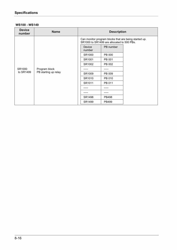
8-16
Specifications
WS100 - WS149 Device number Name Description
SR1000 to SR1499
Program block PB starting up relay
Can monitor program blocks that are being started up. SR1000 to SR1499 are allocated to 500 PBs.
Device number
PB number
SR1000 PB 000 SR1001 PB 001
SR1002 PB 002 ----- ----- SR1009 PB 009 SR1010 PB 010 SR1011 PB 011 ----- -----
----- ----- SR1498 PB498 SR1499 PB499

8.1 CPU Unit Specifications
8-17
8.1.6 List of System Data Registers
SD0 – SD39 Device number Name Description
SD0 Self-diagnostic error code Stores the error code when a self-diagnosis error occurred.
SD1 Alarm Occurrence Unit Slot No. Saves the slot number of the unit where an alarm has occurred.
SD2 Error Occurrence Unit Slot No. Saves the slot number of the unit where an error has occurred.
SD3 Warning Occurrence Unit Slot No. Saves the slot number of the unit where a warning has occurred.
SD4 Verification Error Occurrence Unit Slot No.
Saves the slot number of the unit where a verification error has occurred.
SD5 Installation error detection slot No. Saves the slot number of the unit where an installation error was detected.
SD6 (Not used)
SD7 Operation error occurrence PB number (hold type)
Saves the PB number where the first operation error occurred after the unit has started operating.
SD8 Operation error occurrence address (hold type) (32-bit lower-level address) Saves the address where the first operation error occurred
after the unit has started operating. Perform monitoring using 32-bit data.
SD9 Operation error occurrence address (hold type) (32-bit higher-level address)
SD10 Operation error occurrence PB number (latest type)
Saves the PB number where an operation error occurred. Every time a new error occurs, the data are updated. The value '0' is recorded at the start of the scan.
SD11 Operation error occurrence address (latest type) (32-bit lower-level address)
Saves the address where an operation error occurred. Every time a new error occurs, the data are updated. The value '0' is recorded at the start of the scan. Perform monitoring using 32-bit data. SD12
Operation error occurrence address (latest type) (32-bit higher-level address)
SD13 to SD18 (Not used)
SD19 RING counter 2.5 ms The saved value is increased by one every time the respective time unit has passed. (H0 to HFFFF) Current values of SD19 to SD21 can only be read when SD19 to SD21 are directly specified and read by MV instruction. The scan start value is read by other instructions.
SD20 RING counter 10 μs
SD21 RING counter 100 μs
SD22 Scan time (current value) Saves the current value.
[Saved value (decimal)] x 10 μs scan time indication: Indicates operation cycle time in the RUN mode only. Max. and Min. values are cleared at switching between the RUN mode and the PROG. mode.
SD23 Scan time (minimum value) Stores the minimum value.
SD24 Scan time (maximum value) Saves the maximum value.
SD25 to SD26 (Not used)
SD27 Interval for PB for execution at a specified interval Saves interval for PB for execution at a specified interval.
SD28 (Not used)
SD29 Ethernet communication error code
Saves the error code when the Ethernet communication instruction is executed.
SD30 SD card access instruction execution result
Error codes while the SD card access instruction is executed are stored.
SD31 to SD39 (Not used)
(Note 1): SD0 to SD5 are available only when the corresponding system relays SR0 to SR5 are on.
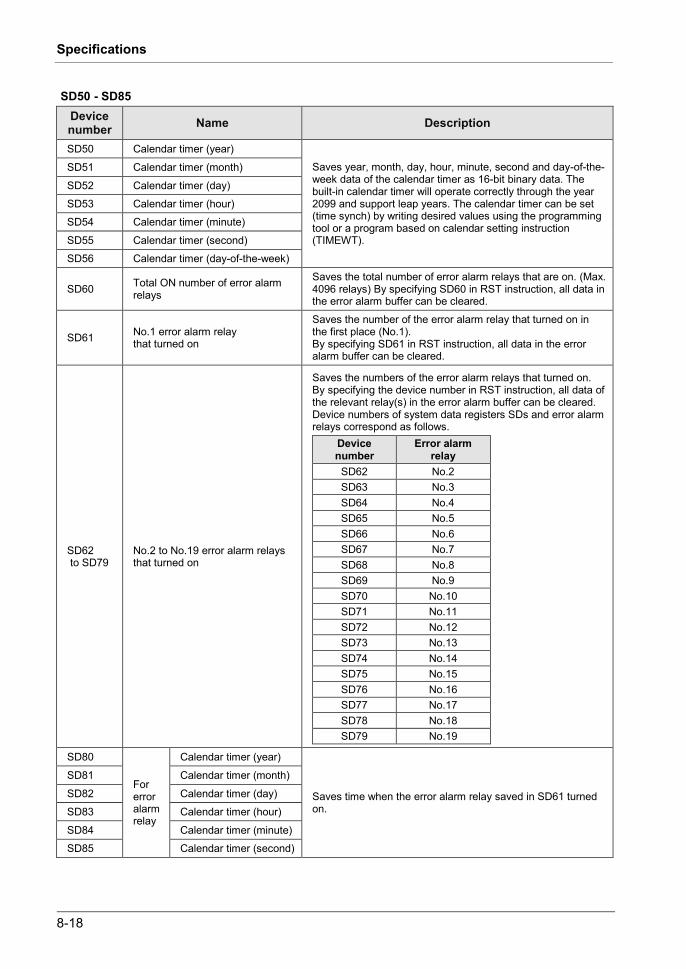
8-18
Specifications
SD50 - SD85 Device number Name Description
SD50 Calendar timer (year) Saves year, month, day, hour, minute, second and day-of-the-week data of the calendar timer as 16-bit binary data. The built-in calendar timer will operate correctly through the year 2099 and support leap years. The calendar timer can be set (time synch) by writing desired values using the programming tool or a program based on calendar setting instruction (TIMEWT).
SD51 Calendar timer (month)
SD52 Calendar timer (day) SD53 Calendar timer (hour) SD54 Calendar timer (minute)
SD55 Calendar timer (second) SD56 Calendar timer (day-of-the-week)
SD60 Total ON number of error alarm relays
Saves the total number of error alarm relays that are on. (Max. 4096 relays) By specifying SD60 in RST instruction, all data in the error alarm buffer can be cleared.
SD61 No.1 error alarm relay that turned on
Saves the number of the error alarm relay that turned on in the first place (No.1). By specifying SD61 in RST instruction, all data in the error alarm buffer can be cleared.
SD62 to SD79
No.2 to No.19 error alarm relays that turned on
Saves the numbers of the error alarm relays that turned on. By specifying the device number in RST instruction, all data of the relevant relay(s) in the error alarm buffer can be cleared. Device numbers of system data registers SDs and error alarm relays correspond as follows.
Device number
Error alarm relay
SD62 No.2 SD63 No.3 SD64 No.4 SD65 No.5 SD66 No.6 SD67 No.7 SD68 No.8 SD69 No.9 SD70 No.10 SD71 No.11 SD72 No.12 SD73 No.13 SD74 No.14 SD75 No.15 SD76 No.16 SD77 No.17 SD78 No.18 SD79 No.19
SD80
For error alarm relay
Calendar timer (year)
Saves time when the error alarm relay saved in SD61 turned on.
SD81 Calendar timer (month)
SD82 Calendar timer (day) SD83 Calendar timer (hour)
SD84 Calendar timer (minute) SD85 Calendar timer (second)

8.1 CPU Unit Specifications
8-19
SD100 - SD115 and SD120 - SD125 (For logging trace control) Device number Name Description
SD100 Buffer free space for LOG0
Saves free space of buffer memory during logging. Unit: kB
SD101 Buffer free space for LOG1
SD102 Buffer free space for LOG2 SD103 Buffer free space for LOG3 SD104 Buffer free space for LOG4
SD105 Buffer free space for LOG5 SD106 Buffer free space for LOG6 SD107 Buffer free space for LOG7 SD108 Buffer free space for LOG8 SD109 Buffer free space for LOG9 SD110 Buffer free space for LOG10
SD111 Buffer free space for LOG11 SD112 Buffer free space for LOG12 SD113 Buffer free space for LOG13 SD114 Buffer free space for LOG14 SD115 Buffer free space for LOG15 SD120 Buffer overflow counter for LOG0
Saves the number of times buffer overflow flags (e.g. SR104 for LOG0) turn on. For checking the number of times logging data is lost during the buffer overflow, register the buffer overflow counter as logging data.
SD121 Buffer overflow counter for LOG1
SD122 Buffer overflow counter for LOG2
SD123 Buffer overflow counter for LOG3 SD124 Buffer overflow counter for LOG4 SD125 Buffer overflow counter for LOG5 SD126 Buffer overflow counter for LOG6 SD127 Buffer overflow counter for LOG7 SD128 Buffer overflow counter for LOG8
SD129 Buffer overflow counter for LOG9 SD130 Buffer overflow counter for LOG10 SD131 Buffer overflow counter for LOG11 SD132 Buffer overflow counter for LOG12 SD133 Buffer overflow counter for LOG13 SD134 Buffer overflow counter for LOG14
SD135 Buffer overflow counter for LOG15

8-20
Specifications
8.1.7 Error/Warning Codes Tables
Error codes 1 to 6 Code Name Operation Error contents and steps to take 1 CPU hardware error 1 Stop
There may be a hardware problem. Please contact your dealer. 2 CPU hardware error 2 Stop
3 I/O bus power supply error (including "no end cover")
Stop
Error in the I/O bus part is probable, such that the end unit has not been attached. Double-check the attachment status of units. This error also occurs when an expansion cable is removed during operation.
4 Unit attachment limit exceeded Stop is probable that the unit attachment limit has been exceeded.
Double-check the configuration.
5 Project data error Stop Turns on when there is an error in project data.
6 Expansion unit power supply synchronization error
Stop
Turns on when there is an error in the expansion block side such that the power to the expansion unit is not on or the expansion cable is not connected correctly when the power turns on. The wait time until the power turns on can be set in the I/O map configuration dialog box.
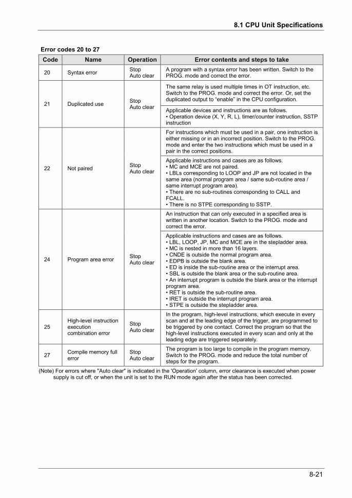
8.1 CPU Unit Specifications
8-21
Error codes 20 to 27 Code Name Operation Error contents and steps to take
20 Syntax error Stop Auto clear
A program with a syntax error has been written. Switch to the PROG. mode and correct the error.
21 Duplicated use Stop Auto clear
The same relay is used multiple times in OT instruction, etc. Switch to the PROG. mode and correct the error. Or, set the duplicated output to “enable” in the CPU configuration.
Applicable devices and instructions are as follows. • Operation device (X, Y, R, L), timer/counter instruction, SSTP instruction
22 Not paired Stop Auto clear
For instructions which must be used in a pair, one instruction is either missing or in an incorrect position. Switch to the PROG. mode and enter the two instructions which must be used in a pair in the correct positions. Applicable instructions and cases are as follows. • MC and MCE are not paired. • LBLs corresponding to LOOP and JP are not located in the same area (normal program area / same sub-routine area / same interrupt program area). • There are no sub-routines corresponding to CALL and FCALL. • There is no STPE corresponding to SSTP.
24 Program area error Stop Auto clear
An instruction that can only executed in a specified area is written in another location. Switch to the PROG. mode and correct the error.
Applicable instructions and cases are as follows. • LBL, LOOP, JP, MC and MCE are in the stepladder area. • MC is nested in more than 16 layers. • CNDE is outside the normal program area. • EDPB is outside the blank area. • ED is inside the sub-routine area or the interrupt area. • SBL is outside the blank area or the sub-routine area. • An interrupt program is outside the blank area or the interrupt program area. • RET is outside the sub-routine area. • IRET is outside the interrupt program area. • STPE is outside the stepladder area.
25 High-level instruction execution combination error
Stop Auto clear
In the program, high-level instructions, which execute in every scan and at the leading edge of the trigger, are programmed to be triggered by one contact. Correct the program so that the high-level instructions executed in every scan and only at the leading edge are triggered separately.
27 Compile memory full error
Stop Auto clear
The program is too large to compile in the program memory. Switch to the PROG. mode and reduce the total number of steps for the program.
(Note) For errors where "Auto clear" is indicated in the 'Operation' column, error clearance is executed when power supply is cut off, or when the unit is set to the RUN mode again after the status has been corrected.
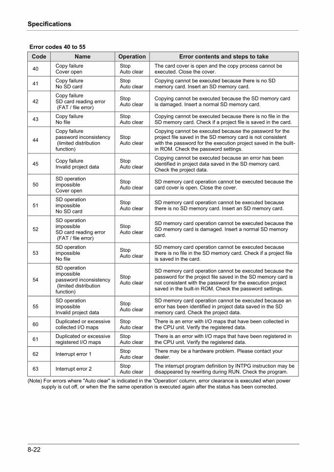
8-22
Specifications
Error codes 40 to 55 Code Name Operation Error contents and steps to take
40 Copy failure Cover open
Stop Auto clear
The card cover is open and the copy process cannot be executed. Close the cover.
41 Copy failure No SD card
Stop Auto clear
Copying cannot be executed because there is no SD memory card. Insert an SD memory card.
42 Copy failure SD card reading error (FAT / file error)
Stop Auto clear
Copying cannot be executed because the SD memory card is damaged. Insert a normal SD memory card.
43 Copy failure No file
Stop Auto clear
Copying cannot be executed because there is no file in the SD memory card. Check if a project file is saved in the card.
44
Copy failure password inconsistency (limited distribution function)
Stop Auto clear
Copying cannot be executed because the password for the project file saved in the SD memory card is not consistent with the password for the execution project saved in the built-in ROM. Check the password settings.
45 Copy failure Invalid project data
Stop Auto clear
Copying cannot be executed because an error has been identified in project data saved in the SD memory card. Check the project data.
50 SD operation impossible Cover open
Stop Auto clear
SD memory card operation cannot be executed because the card cover is open. Close the cover.
51 SD operation impossible No SD card
Stop Auto clear
SD memory card operation cannot be executed because there is no SD memory card. Insert an SD memory card.
52
SD operation impossible SD card reading error (FAT / file error)
Stop Auto clear
SD memory card operation cannot be executed because the SD memory card is damaged. Insert a normal SD memory card.
53 SD operation impossible No file
Stop Auto clear
SD memory card operation cannot be executed because there is no file in the SD memory card. Check if a project file is saved in the card.
54
SD operation impossible password inconsistency (limited distribution function)
Stop Auto clear
SD memory card operation cannot be executed because the password for the project file saved in the SD memory card is not consistent with the password for the execution project saved in the built-in ROM. Check the password settings.
55 SD operation impossible Invalid project data
Stop Auto clear
SD memory card operation cannot be executed because an error has been identified in project data saved in the SD memory card. Check the project data.
60 Duplicated or excessive collected I/O maps
Stop Auto clear
There is an error with I/O maps that have been collected in the CPU unit. Verify the registered data.
61 Duplicated or excessive registered I/O maps
Stop Auto clear
There is an error with I/O maps that have been registered in the CPU unit. Verify the registered data.
62 Interrupt error 1 Stop Auto clear
There may be a hardware problem. Please contact your dealer.
63 Interrupt error 2 Stop Auto clear
The interrupt program definition by INTPG instruction may be disappeared by rewriting during RUN. Check the program.
(Note) For errors where "Auto clear" is indicated in the 'Operation' column, error clearance is executed when power supply is cut off, or when the the same operation is executed again after the status has been corrected.

8.1 CPU Unit Specifications
8-23
Error codes 80 to 106 Code Name Operation Error contents and steps to take
80 Unit alarm occurrence Select (Default stop)
An alarm has occurred in an attached unit. Check the status of the unit in the slot number saved in the system data register SD1.
81 Unit error occurrence Select (Default stop)
An error has occurred in an attached unit. Check the status of the unit in the slot number saved in the system data register SD2. Verify the configuration settings.
82 Unit verification error detection
Select (Default stop)
Unit wiring condition has changed compared to that at the time of power-up. Check the status of the unit in the slot number saved in the system data register SD4.
83 Registered unit number inconsistency
Select (Default stop)
The number of units differs from that registered in the I/O map. Check the I/O map and the attachment status.
84 Unit initial completed Waiting timeout
Select (Default stop)
An error has occurred during the unit initial operation. Check the unit status.
85 Unit configuration data inconsistency with applicable unit
Select (Default stop)
The unit's configuration data is not consistent with the applicable unit. Check the I/O map and the configuration data.
86 Operation error Select (Default stop)
An operation error has occurred. Reasons for an operation error vary by instruction. Refer to the Instruction Manual, etc. and correct the appropriate reasons. PB and address where an operation error has occurred are saved in the system data registers SD7 to SD12.
100 Bus current error Select (Default continue) A bus error is probable. Please contact your dealer.
104 Service power supply current error
Select (Default continue)
An error has been detected in the GT power supply terminal part. Check if it is correctly connected.
105 CPU temperature error 1 Select (Default continue) A temperature rise has been detected in hardware. In
general, select "Continue". 106 CPU temperature error 2 Select
(Default continue) (Note 1) For errors where "Select" is indicated in the 'Operation' column, either "Stop" or "Continue" can be selected
in the configuration menu.

8-24
Specifications
Error codes 120 to 127, 1000 to 2999 Code Name Operation Error contents and steps to take
120 RTC data error Continue An error has been detected in clock data of the calendar timer.
121 Power supply unit lifetime warning Continue It is alarmed that the power supply unit is close to its
lifetime. Replace the power supply unit.
122 Battery voltage decline Continue Voltage of the optional battery has declined. Replace the battery. If no battery is used, disable battery error alarm in the CPU configuration.
123 Gold capacitor voltage decline Continue It is alarmed that voltage of the built-in gold capacitor
of the CPU unit has declined. Charge the CPU unit.
124 SNTP time acquisition failure Continue Acquisition of time data has failed during time synch
via LAN port.
125 Logging settings mismatch Continue An error has been detected in logging data settings.
126 Logging data error Continue An error has been detected in logging data. 127 Comment data error Continue An error has been detected in comment data. 1000 to 1999
Error by ERR instruction Stop An error as specified by ERR instruction in the user program has occurred. Handle the error in accordance with the specified detection conditions. 2000
to 2999
Error by ERR instruction Continue
(Note 1) If an RTC data error is detected, the date is set to "April 1, 2012".

8.1 CPU Unit Specifications
8-25
Error codes for SCU unit and built-in SCU unit
Error code Name
0x7001 Mode setting/changing error
0x7002 Parameter setting error
0x7003 Sent data amount error
0x7005 Communication cassette verification error
0x7006 PLC link registration exceeded
0x7007 Duplicated PLC link area block number
0x70E0 Configuration data version error Warning codes for SCU unit and built-in SCU unit
Warning code Name
0x7011 Received data error
0x7012 Receive buffer overflow
0x7013 Receive buffer FULL error
0x7021 Transmission error
0x7022 Duplicated unit number
0x7023 Duplicated PLC link area
0x7024 PLC link error
0x7025 Maximum unit number inconsistency
0x7026 PLC link stop state

8-26
Specifications
Error codes for built-in ET-LAN unit
Error code Name
8001H Local node address setting error
8002H Subnet mask setting error
8003H Default router (gateway) IP address setting error
8004H DNS address setting error
8009H Initial processing error
8014H Address setting error
8015H Operation mode setting error Warning codes for built-in ET-LAN unit
Warning code Name
8005H DHCP acquisition result error (Previously: Local node IP address acquisition error)
8006H DHCP (Ipv4) error
8007H DHCP (Ipv6) error
8008H Router (Ipv6) error
800AH Duplicated address
800CH Static route setting error
8011-8013H OPEN request error
8016-8017H Name resolution failure
8018H Connection establishment timeout
8021-8026H Transmission error
8027-8029H Reception error
802AH Packet processing error
8031H SNTP time acquisition error
8032H
8041H Connection unused time elapsed
8042H Ethernet cable disconnection

8.2 Power Supply Unit Specifications
8-27
8.2 Power Supply Unit Specifications
8.2.1 General Specifications
Items Description Operating ambient temperature 0 to +55C
Operating ambient humidity 10 to 95%RH (at 25C, no-condensing)
Storage ambient temperature -40 to +70C
Storage ambient humidity 10 to 95%RH (at 25C, no-condensing)
Breakdown voltage
All the AC inputs All the DC outputs 2300 V AC, 1 minute (Note)
All the AC inputs Protective earth terminals 1500 V AC, 1 minute (Note)
All the AC inputs All the alarms 2300 V AC, 1 minute (Note)
Insulation resistance (test voltage: 500V DC)
All the AC inputs All the DC outputs
All the AC inputs Protective earth terminals
All the AC inputs All the alarms
100 M or larger
Vibration resistance
Based on JIS B 3502 and IEC 61131-2: 5 to 8.4 Hz, half amplitude 3.5 mm 8.4 to 150 Hz, constant acceleration 9.8 m/s2 X, Y and Z axes, 10 sweeps (1 octave/mm)
Shock resistance Based on JIS B 3502 and IEC 61131-2 147 m/s2, X, Y and Z axes, times
Noise resistance 1500 V[p-p] with pulse widths of 50 ns or 1 μs (based on in-house measurements)
Environment Free from corrosive gases and excessive dust.
EU Directive applicable standard EMC Directive: EN 61131-2, Low-Voltage Directive: EN 61131-2
Overvoltage category Category II or lower
Pollution degree Pollution degree 2
Weight (main unit) AFP7PSA1: approx. 240g AFP7PSA2: approx. 290g
(Note) Cutoff current: 10 mA (Factory default setting)

8-28
Specifications
8.2.2 Performance Specifications
Items Description Model number AFP7PSA1 AFP7PSA2
Input
Rated input voltage 100 to 240V AC
Input voltage amplitude range 85 to 264V AC
Rated frequency 50 / 60 Hz
Frequency range 47 to 63 Hz
Phases Single-phase
Input current 0.75A or less 1.25A or less
Inrush current 40 A (0-P) or less; Cold start
Leakage current 0.75 mA or less between AC input and protective earth terminals
Momentary power drop time 10 ms or more
Output Rated output current (Note 1) 24V DC, 1A 24V DC, 1.8A
Overcurrent protection (Note 2) On
Remaining service life counting function Not available Available
Guaranteed lifetime 27,000 hours (+55C)
Fuse Built-in (Replacement is not available)
(Note 1) Use the unit within the rated output current. (Note 2) Oscillation is stopped during protected operation.
To recover, turn off the input and then on again. Wait at least 180 seconds before turning the input on again.
8.2.3 Alarm Output Specifications
Items Description Contact capacity 1A 30V DC
Alarm contact operations Contact OFF at CPU alarm occurrence

8.3 Dimensions
8-29
8.3 Dimensions
8.3.1 Power Supply Unit
90
50
(12.8) 80 4
90
70

8-30
Specifications
8.3.2 CPU Unit (CPS4*/CPS3*)
90
40 (10) 80 4
8.3.3 CPU Unit (CPS21)
90
34 (10) 80 4

8.3 Dimensions
8-31
8.3.4 Terminal Block Type Unit (1)
Applicable units: Digital I/O unit (16-point), Analog input unit, Analog output unit
90
28 (18) 80 4
8.3.5 Terminal Block Type Unit (2)
Applicable units: Thermocouple multi-analog input unit, RTD input unit
90
28 (10) 80 4
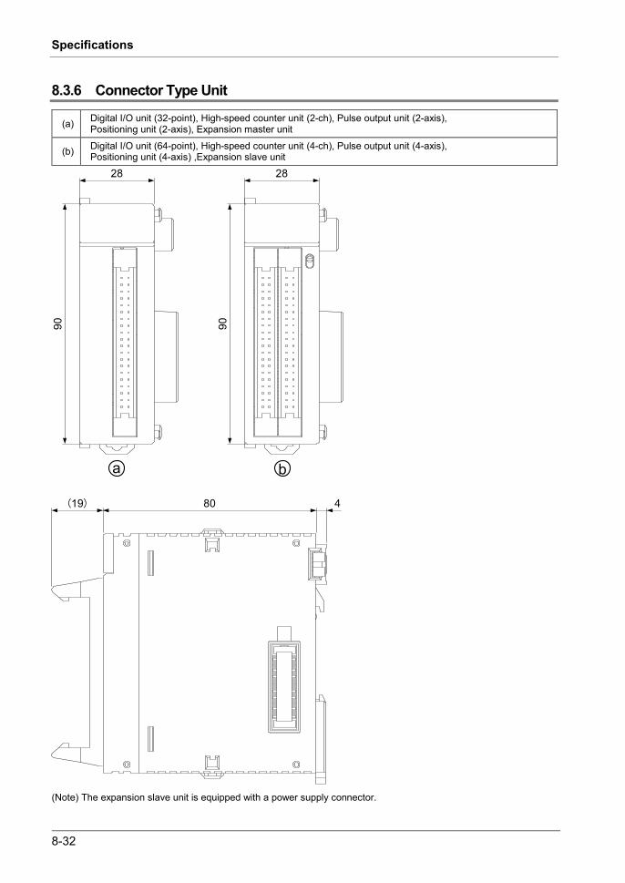
8-32
Specifications
8.3.6 Connector Type Unit
(a) Digital I/O unit (32-point), High-speed counter unit (2-ch), Pulse output unit (2-axis), Positioning unit (2-axis), Expansion master unit
(b) Digital I/O unit (64-point), High-speed counter unit (4-ch), Pulse output unit (4-axis), Positioning unit (4-axis) ,Expansion slave unit
90
28
(19) 80 4
90
28
a b
(Note) The expansion slave unit is equipped with a power supply connector.
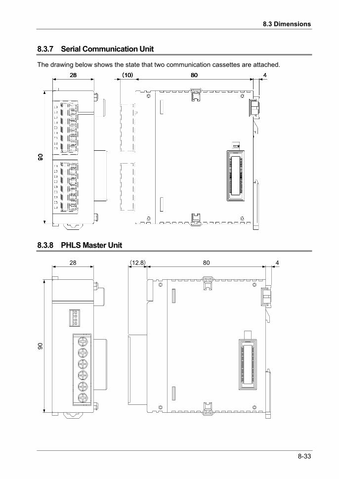
8.3 Dimensions
8-33
8.3.7 Serial Communication Unit
The drawing below shows the state that two communication cassettes are attached.
8.3.8 PHLS Master Unit
90
28 (12.8) 80 4

8-34
Specifications
8.3.9 End Unit
90
14.5 80 4

8.3 Dimensions
8-35
8.3.10 Figures of Unit Combination
When the power supply unit AFP7PSA1 is used
FP7 system full width = Power supply unit AFP7PSA1 + CPU unit + n devices (input/output units and intelligent units) + End unit
= 50mm + 40mm + (n x 28mm) + 14.5mm = 104.5mm + (n x 28mm)
When the power supply unit AFP7PSA2 is used
FP7 system full width = Power supply unit AFP7PSA2 + CPU unit + n devices (input/output units and intelligent units) + End unit
= 70mm + 40mm + (n x 28mm) + 14.5mm = 124.5mm + (n x 28mm)

8-36
Specifications
When no power supply unit is used
FP7 system full width = CPU unit + n devices (input/output units and intelligent units) + End unit
= 40mm + (n x 28mm) + 14.5mm = 54.5mm + (n x 28mm)
Note) The size of the CPU unit is 6mm shorter when using CPS21.

Record of changes Manual No. Date Record of Changes
WUME-FP7CPUH-01 Mar.2013 1st Edition
WUME-FP7CPUH-02 Jun.2013 2nd Edition
- Added new models
CPU units CPS3E and CPS3
I/O units Y32P, Y64P and XY64D2P
- Error correction
WUME-FP7CPUH-03 Oct.2013 3rd Edition
- Added new models
High-speed counter unit
WUME-FP7CPUH-04 Dec.2013 4th Edition
- Added new models
Serial communication unit AFP7NSC
Communication cassette (Ethernet type) AFP7CCET1
CPU unit (Ver.2): AFP7CPS41*, AFP7CPS31*
Pulse output unit: AFP7PG02*, AFP7PG04*
Analog I/O cassette: AFP7FCA21
Analog input cassette: AFP7FCAD2
Thermocouple input cassette: AFP7FCTC2
- Error correction
WUME-FP7CPUH-05 Aug.2014 5th Edition
- Added new models
Thermocouple Multi-analog input unit AFP7TC8
RTD input unit AFP7RTD8
Analog input unit (8ch) AFP7AD8
Expansion master unit AFP7EXPM
Expansion slave unit AFP7EXPS
- Added the information of new GUI for FPWINGR7
- Error correction
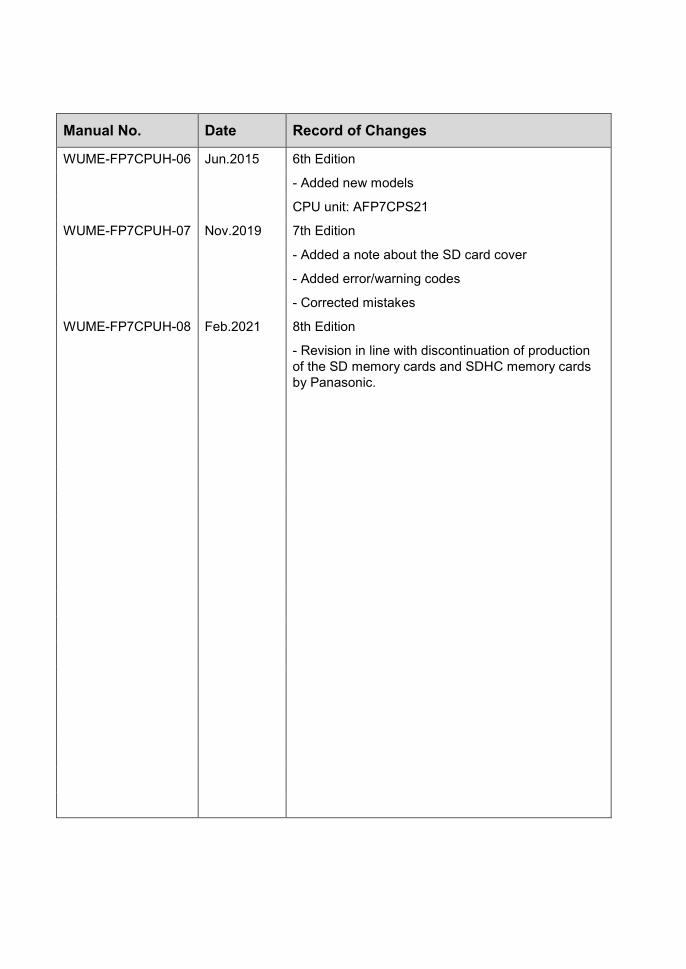
Manual No. Date Record of Changes
WUME-FP7CPUH-06 Jun.2015 6th Edition
- Added new models
CPU unit: AFP7CPS21
WUME-FP7CPUH-07 Nov.2019 7th Edition
- Added a note about the SD card cover
- Added error/warning codes
- Corrected mistakes
WUME-FP7CPUH-08 Feb.2021 8th Edition
- Revision in line with discontinuation of production of the SD memory cards and SDHC memory cards by Panasonic.

Order Placement Recommendations and Considerations The Products and Specifications listed in this document are subject to change (including
specifications, manufacturing facility and discontinuing the Products) as occasioned by the improvements of Products. Consequently, when you place orders for these Products, Panasonic Industrial Devices SUNX asks you to contact one of our customer service representatives and check that the details listed in the document are commensurate with the most up-to-date information.
[Safety precautions] Panasonic Industrial Devices SUNX is consistently striving to improve quality and reliability.
However, the fact remains that electrical components and devices generally cause failures at a given statistical probability. Furthermore, their durability varies with use environments or use conditions. In this respect, check for actual electrical components and devices under actual conditions before use. Continued usage in a state of degraded condition may cause the deteriorated insulation. Thus, it may result in abnormal heat, smoke or fire. Carry out safety design and periodic maintenance including redundancy design, design for fire spread prevention, and design for malfunction prevention so that no accidents resulting in injury or death, fire accidents, or social damage will be caused as a result of failure of the Products or ending life of the Products.
The Products are designed and manufactured for the industrial indoor environment use. Makesure standards, laws and regulations in case the Products are incorporated to machinery, system,apparatus, and so forth. With regard to the mentioned above, confirm the conformity of theProducts by yourself.
Do not use the Products for the application which breakdown or malfunction of Products may cause damage to the body or property.i) usage intended to protect the body and ensure security of lifeii)application which the performance degradation or quality problems, such as breakdown,of the Products may directly result in damage to the body or propertyIt is not allowed the use of Products by incorporating into machinery and systems indicated
below because the conformity, performance, and quality of Products are not guaranteed undersuch usage.i) transport machinery (cars, trains, boats and ships, etc.)ii) control equipment for transportationiii) disaster-prevention equipment / security equipmentiv) control equipment for electric power generationv) nuclear control systemvi) aircraft equipment, aerospace equipment, and submarine repeatervii) burning appliancesviii) military devicesix) medical devices except for general controlsx) machinery and systems which especially require the high level of reliability and safety
[Acceptance inspection] In connection with the Products you have purchased from us or with the Products delivered to your premises, please perform an acceptance inspection with all due speed and, in connection with the handling of our Products both before and during the acceptance inspection, please give full consideration to the control and preservation of our Products.
[Warranty period] Unless otherwise stipulated by both parties, the warranty period of our Products is three year after the purchase by you or after their delivery to the location specified by you. The consumable items such as battery, relay, filter and other supplemental materials are excluded from the warranty.
[Scope of warranty] In the event that Panasonic Industrial Devices SUNX confirms any failures or defects of the Products by reasons solely attributable to Panasonic Industrial Devices SUNX during the warranty period, Panasonic Industrial Devices SUNX shall supply the replacements of the Products, parts or replace and/or repair the defective portion by free of charge at the location where the Products were purchased or delivered to your premises as soon as possible. However, the following failures and defects are not covered by warranty and we are not responsible for such failures and defects. (1) When the failure or defect was caused by a specification, standard, handling method,
etc. which was specified by you. (2) When the failure or defect was caused after purchase or delivery to your premises by
an alteration in construction, performance, specification, etc. which did not involveus.
(3) When the failure or defect was caused by a phenomenon that could not be predicted bythe technology at purchasing or contracted time.
(4) When the use of our Products deviated from the scope of the conditions and environmentset forth in the instruction manual and specifications.
(5) When, after our Products were incorporated into your products or equipment for use, damageresulted which could have been avoided if your products or equipment had been equippedwith the functions, construction, etc. the provision of which is accepted practice inthe industry.
(6) When the failure or defect was caused by a natural disaster or other force majeure.(7) When the equipment is damaged due to corrosion caused by corrosive gases etc. in the
surroundings.
The above terms and conditions shall not cover any induced damages by the failure or defects of the Products, and not cover your production items which are produced or fabricated by usingthe Products. In any case, our responsibility for compensation is limited to the amount paid for the Products.
[Scope of service] The cost of delivered Products does not include the cost of dispatching an engineer, etc. In case any such service is needed, contact our sales representative.


Please contact ..........
© Panasonic Industrial Devices SUNX Co., Ltd. 2021WUME-FP7CPUH-08February, 2021
Panasonic Industrial Devices SUNX Co., Ltd. https://panasonic.net/id/pidsx/global
Please visit our website for inquiries and about our sales network.