fp-524d instruction manual - teledyne · instruction manual . detcon model fp-524d . pgm 1 pgm 2...
TRANSCRIPT

INSTRUCTION MANUAL Detcon Model FP-524D
PGM 1
PGM 2
MODEL FP-524DHOUSTON, TEXAS
FLT 1 2 CAL
MicroSafe LEL Gas SensorALM ALM
TM
FP-524D Combustible Gas Sensor (0 – 100% LEL)
DETCON, Inc. 4055 Technology Forest Blvd, Suite 100,
The Woodlands, Texas 77381 Ph.281.367.4100 / Fax 281.298.2868
www.detcon.com
June 06, 2018 • Document #3597 • Revision 1.6

Model FP-524D
FP-524D Instruction Manual ii
Page left intentionally blank

Model FP-524D
FP-524D Instruction Manual iii
Table of Contents 1. Introduction ..................................................................................................................................................1
1.1 Description .......................................................................................................................................... 1 1.2 Modular Mechanical Design ............................................................................................................... 3
2. Installation ....................................................................................................................................................5 2.1 Operational Guidelines for Safe Use .................................................................................................. 5 2.2 Sensor Placement ................................................................................................................................ 5 2.3 Sensor Contaminants and Interference ............................................................................................... 6 2.4 Mounting Installation .......................................................................................................................... 7 2.5 Electrical Installation .......................................................................................................................... 7 2.6 Field Wiring ........................................................................................................................................ 9 2.7 Remote Mounting Installation .......................................................................................................... 10
2.7.1 Bridge Voltage Adjustment .......................................................................................................... 11 2.8 Initial Start Up................................................................................................................................... 11
3. Operation .................................................................................................................................................... 12 3.1 Programming Magnet Operating Instructions ................................................................................... 12 3.2 Operator Interface ............................................................................................................................. 13 3.3 Normal Operation ............................................................................................................................. 15 3.4 Calibration Mode (AutoZero and AutoSpan) ................................................................................... 15
3.4.1 AutoZero ....................................................................................................................................... 15 3.4.2 AutoSpan ...................................................................................................................................... 16
3.5 Program Mode .................................................................................................................................. 17 3.5.1 View Sensor Status ....................................................................................................................... 18 3.5.2 Set AutoSpan Level ...................................................................................................................... 20 3.5.3 Set Gas Factor ............................................................................................................................... 20 3.5.4 Set Cal Factor ............................................................................................................................... 21 3.5.5 Set Bridge Voltage ........................................................................................................................ 22 3.5.6 Signal Output Check ..................................................................................................................... 23 3.5.7 Restore Factory Defaults .............................................................................................................. 23 3.5.8 Alarm 1 and 2 Settings ................................................................................................................. 24 3.5.9 Fault Settings ................................................................................................................................ 24
3.6 Program Features .............................................................................................................................. 25 3.6.1 Operational Features ..................................................................................................................... 25 3.6.2 Fault Diagnostic/Failsafe Features ............................................................................................... 25
4. Service and Maintenance ............................................................................................................................ 28 5. Troubleshooting Guide ............................................................................................................................... 30 6. Customer Support and Service Policy ........................................................................................................ 33 7. FP-524D Sensor Warranty .......................................................................................................................... 34 8. Appendix .................................................................................................................................................... 35
8.1 Specifications .................................................................................................................................... 35 8.2 Spare Parts, Sensor Accessories, Calibration Equipment ................................................................. 37 8.3 Revision Log ..................................................................................................................................... 38

Model FP-524D
FP-524D Instruction Manual iv
List of Figures Figure 1 Sensor Assembly Front View ................................................................................................................ 1 Figure 2 Sensor Cell Construction ...................................................................................................................... 2 Figure 3 Wheatstone Bridge ................................................................................................................................. 2 Figure 4 Response Curves .................................................................................................................................... 2 Figure 5 Circuit Functional Block Diagram ......................................................................................................... 3 Figure 6 FP-524D Transmitter Module ................................................................................................................ 3 Figure 7 LEL Sensor Housing with replaceable Sensor ....................................................................................... 4 Figure 8 Base Connector Board ........................................................................................................................... 4 Figure 9 Typical Outline and Mounting Dimensions ........................................................................................... 7 Figure 10 Typical Installation .............................................................................................................................. 8 Figure 11 Sensor Connector PCB......................................................................................................................... 9 Figure 12 Remote Sensor Wiring Diagram ....................................................................................................... 10 Figure 13 Magnetic Programming Tool ............................................................................................................. 12 Figure 14 Magnetic Programming Switches .................................................................................................... 12 Figure 15 FP-524D Software Flowchart ........................................................................................................... 14 Figure 16 Replaceable Combustible Gas Sensor ............................................................................................... 30
List of Tables Table 1 Wire Gauge vs. Distance ......................................................................................................................... 9 Table 2 Gas/Cal Factors ..................................................................................................................................... 21
Shipping Address: 4055 Technology Forest Blvd, Suite 100, The Woodlands Texas 77381 Mailing Address: P.O. Box 8067, The Woodlands Texas 77387-8067
Phone: 888.367.4286, 281.367.4100 • Fax: 281.292.2860 • www.detcon.com • [email protected]

Model FP-524D
FP-524D Instruction Manual Rev. 1.6 Page 1 of 39
1. Introduction
1.1 Description Detcon Model FP-524D LEL Combustible sensors are non-intrusive “Smart” sensors designed to detect and monitor combustible gases in air. Range of detection is 0-100% LEL (Lower Explosive Limit). The sensor features an LED display of current reading, fault, and calibration status. The Sensor is equipped with a standard analog 4-20mA output. A primary feature of the sensor is its method of automatic calibration, which guides the user through each step via fully scripted instructions displayed on the LED display. The microprocessor-supervised electronics are packaged as a plug-in replaceable Transmitter Module that is housed in an explosion proof junction box. The Transmitter Module includes a four character alpha/numeric LED used to display sensor readings, and the sensor’s menu driven features when the hand-held programming magnet is used.
MODEL FP-524DHOUSTON, TEXAS
MicroSafe LEL Gas Sensor
PGM 1
PGM 2
FLT 1 2 CALALM ALM
TM
Figure 1 Sensor Assembly Front View
Catalytic Bead (Pellistor) Sensor Technology
The sensor technology is a poison-resistant catalytic bead type. Catalytic bead sensors show a strong response to a long list of combustible gases. The sensor is supplied as a matched-pair of detector elements mounted in a plug-in replaceable module. One bead is a catalytically active detector and the other is a non-active reference detector. Each detector consists of a fine platinum wire coil embedded in aluminum oxide. A catalytic mixture is applied to the active detector while the reference detector is treated so that oxidation of the gas does not occur. This technique is referred to as non-selective and may be used to monitor most any combustible gas. Detcon catalytic bead sensors are specifically designed to be resistant to poisons such as sulfides, chlorides, and silicones. The sensors are characteristically stable and capable of providing reliable performance for periods exceeding 5 years in most industrial environments.

Model FP-524D
FP-524D Instruction Manual Rev. 1.6 Page 2 of 39
Main Housing Insert
Printed Circuit BoardGold Plated Pins
Platinum Wire
Construction of Detector
Bead
Catalyst
Alumina BeadCatalytic Beads
Figure 2 Sensor Cell Construction
Principle of Operation
Method of detection is by diffusion/adsorption. Air and combustible gases pass through a sintered stainless steel filter and contact the heated surface of both the active and reference detectors. The surface of the active detector promotes oxidation of the combustible gas molecules while the reference detector has been treated not to support this oxidation. The reference detector serves as a means to maintain zero stability over a wide range of temperature and humidity. When combustible gas molecules oxidize on the surface of the active detector, heat is generated, and the resistance of the detector changes. Electronically, the detectors form part of a balanced bridge circuit. As the active detector changes in resistance, the bridge circuit unbalances. This change in output is conditioned by the amplifier circuitry, which is an integral part of the sensor design. The response and clearing characteristics of the sensor are rapid and provide for the continuous and accurate monitoring of ambient air conditions.
Sensor Cell
ZeroAdjust
Output
InputVoltage
Compensator / Reference Bead
Detector / Active Bead
Figure 3 Wheatstone Bridge
Performance Characteristics
The detector elements maintain good sensitivity to combustible gas concentrations in the Lower Explosive Limit (LEL) range, as shown in the response curves in Figure 4. However, for gas concentrations significantly above the LEL range (100% LEL = 5% by volume Methane), the bridge output begins to decrease. Ambiguous readings above the LEL range dictate that alarm control logic be of the latching type, wherein alarms are held in the “ON” position until reset by operations personnel.
Figure 4 Response Curves

Model FP-524D
FP-524D Instruction Manual Rev. 1.6 Page 3 of 39
1.2 Modular Mechanical Design The Model FP-524D Sensor Assembly is completely modular and is made up of four parts:
1) FP-524D Plug-in Transmitter 2) Field Replaceable Combustible Gas Sensor 3) Connector PCB 4) Splash Guard.
FP-524D Plug-in Transmitter
The Plug-in Transmitter Module is a microprocessor-based package that plugs into the connector board located in the explosion proof junction box. Circuit functions include extensive I/O circuit protection, sensor pre-amplifier, sensor temperature control, on-board power supplies, microprocessor, LED display, magnetic programming switches, and a linear 4-20mA DC output. Magnetic program switches located on either side of the LED Display are activated via a hand-held magnetic programming tool, thus allowing non-intrusive operator interface with the Transmitter Module. Calibration can be accomplished without declassifying the area. Electrical classifications are Class I, Division 1, Groups B C D.
Figure 5 Circuit Functional Block Diagram
PGM 1
PGM 2
Model FP-524DHOUSTON, TEXAS
FLT 1 2 CAL
MicroSafe LEL Gas SensorALM ALM
TM
Figure 6 FP-524D Transmitter Module
Field Replaceable Sensor
The Detcon combustible gas sensor is a field proven, replaceable type sensor. It can be accessed and replaced in the field by unthreading the lower half of the sensor housing. The cell can then be unplugged and replaced. The Detcon combustible gas sensor has an infinite shelf life and is supported by a 2 year warranty.
I/O Circuit
Protection 4-20mA
Display
Micro-
Processor
Temperature Control
Pre-Amp Analog 4-20mA Out
Power In Power Supply
Plug-In Sensor
Element

Model FP-524D
FP-524D Instruction Manual Rev. 1.6 Page 4 of 39
Replacable Sensor
Main HousingThreaded Insert O-ring Figure 7 LEL Sensor Housing with replaceable Sensor
NOTE: The Field Replaceable Combustible Gas Sensor housing is constructed from 316 Stainless Steel in order to maximize corrosion resistance in harsh environments. Base Connector PCB The base connector board is mounted in the Junction Box. The connector board includes lug-less terminal connections for incoming power and MA output, and connections for the Combustible Gas Replaceable Sensor.
CustomerWiring
Wiring toLEL Sensor
Figure 8 Base Connector Board

Model FP-524D
FP-524D Instruction Manual Rev. 1.6 Page 5 of 39
2. Installation
2.1 Operational Guidelines for Safe Use
1. Install sensor only in areas with classifications matching with those described on the approval label. Follow all warnings listed on the label.
2. Ensure that the sensor is properly mounted in a vertical orientation with the sensor facing down. When
applying Teflon tape, do not apply to all threads - only use enough to make a good seal (covering about ½ the threads is sufficient). A metal to metal connection is required to ensure earth ground continuity for electrical safety.
3. Use ¾” NPT plugs properly rated for hazardous locations to block any unused connections.
4. Removal of the Junction box cover or threaded sensor housing (612-820000-000) violates the Ex
Proof protection method and hence power must be removed from the sensor prior to its safe removal.
5. Ensure that the housing bottom and plug-in sensor are installed during operation. The housing bottom should be threaded tightly to the sensor housing. Removal of the housing bottom violates the Ex Proof protection method and hence power must be removed from the sensor prior to its safe removal.
6. Proper precautions should be taken during installation and maintenance to avoid the build-up of static
charge on the plastic components of the sensor. These include the splashguard and splashguard adapter.
7. Do not operate the sensor outside of the stated operating temperature limits.
8. Do not operate the sensor outside the stated operating limits for voltage supply.
2.2 Sensor Placement Selection of sensor location is critical to the overall safe performance of the product. Six factors play an important role in selection of sensor locations: (1) Density of the gas to be detected (2) Most probable leak sources within the industrial process (3) Ventilation or prevailing wind conditions (4) Personnel exposure (5) Maintenance access (6) Additional Placement Considerations Density
Placement of sensors relative to the density of the target gas is such that sensors for the detection of heavier than air gases should be located within 4 feet of grade as these heavy gases will tend to settle in low lying areas. For gases lighter than air, sensor placement should be 4-8 feet above grade in open areas or in pitched areas of enclosed spaces.
NOTE: Methane and Hydrogen are lighter than air. Most other combustible gases are heavier than air. Compare the molecular weight, density, or specific gravity of the target gas(es) with that of air to determine appropriate placement.
Model FP-524D
FP-524D Instruction Manual Rev. 1.6 Page 6 of 39
Leak Sources
The most probable leak sources within an industrial process include flanges, valves, and tubing connections of the sealed type where seals may either fail or wear. Other leak sources are best determined by facility engineers with experience in similar processes. Ventilation
Normal ventilation or prevailing wind conditions can dictate efficient location of gas sensors in a manner where the migration of gas clouds is quickly detected. Personnel Exposure
The undetected migration of gas clouds should not be allowed to approach concentrated personnel areas such as control rooms, maintenance or warehouse buildings. A more general approach to selecting sensor location is combining leak source and perimeter protection in the best possible configuration. Maintenance Access
Consideration should be given to providing easy access for maintenance personnel. Consideration should also be given to the consequences of close proximity to contaminants that may foul the sensor prematurely.
NOTE: In all installations the gas sensor should point straight down (refer to Figure 10). Improper sensor orientation may result in false readings and permanent sensor damage.
Additional Placement Considerations
The sensor should not be positioned where it may be sprayed or coated with surface contaminating substances. Painting sensor assemblies is prohibited. Although the sensor is designed to be RFI resistant, it should not be mounted in close proximity to high-powered radio transmitters or similar RFI generating equipment. When possible mount in an area void of high wind, accumulating dust, rain, or splashing from hose spray, direct steam releases, and continuous vibration. If the sensor cannot be mounted away from these conditions then make sure the Detcon Harsh Location Dust Guard accessory is used. Do not mount in locations where temperatures will exceed the operating temperature limits of the sensor. Where direct sunlight leads to exceeding the high temperature-operating limit, use a sunshade to help reduce temperature.
2.3 Sensor Contaminants and Interference Detcon combustible gas sensors may be adversely affected by exposure to certain airborne substances. Loss of sensitivity or corrosion may be gradual if such materials are present in sufficient concentrations. The performance of the detector elements may be temporarily impaired during operation in the presence of substances described as inhibitors. Inhibitors are usually volatile substances containing halogen compounds. Inhibitors include halide compounds such as Cl2, ClO2, F2, HF, HCl, Br2, vinyl chloride, and methyl chloride. Inhibition is typically a temporary effect and the detectors generally recover after short periods of operation back in clean air. Some background gases may act as poisoning agents and have a more damaging effect on the sensor. Although the sensor is designed to be poison resistant, it does have physical limits. Poisoning gases deactivate
Model FP-524D
FP-524D Instruction Manual Rev. 1.6 Page 7 of 39
the active detector’s catalytic ability and cause a permanent reduction in the span sensitivity. Examples of typical poisons are: silicone oils and greases, siloxanes (HMDS), H2S, anti-knock petrol additives, and phosphate esters. Activated carbon filters can be used to provide additional protection from poisoning in most cases. The presence of such inhibitors and poisons in an area does not preclude the use of this sensor technology, although it is likely that the sensor lifetime will be shorter as a result. Use of this sensor in these environments may require more frequent calibration checks to ensure safe system performance.
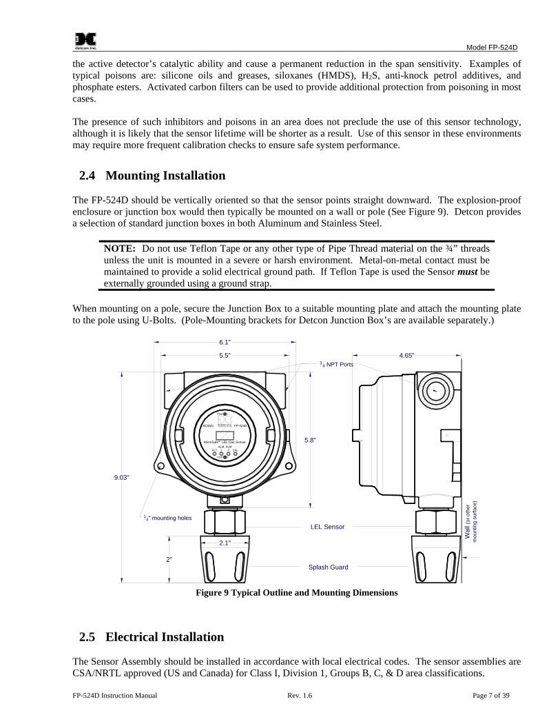
2.4 Mounting Installation The FP-524D should be vertically oriented so that the sensor points straight downward. The explosion-proof enclosure or junction box would then typically be mounted on a wall or pole (See Figure 9). Detcon provides a selection of standard junction boxes in both Aluminum and Stainless Steel.
NOTE: Do not use Teflon Tape or any other type of Pipe Thread material on the ¾” threads unless the unit is mounted in a severe or harsh environment. Metal-on-metal contact must be maintained to provide a solid electrical ground path. If Teflon Tape is used the Sensor must be externally grounded using a ground strap.
When mounting on a pole, secure the Junction Box to a suitable mounting plate and attach the mounting plate to the pole using U-Bolts. (Pole-Mounting brackets for Detcon Junction Box’s are available separately.)
PGM 1
PGM 2
MODEL FP-524DHOUSTON, TEXAS
FLT 1 2 CAL
MicroSafe LEL Gas SensorALM ALM
TM
5.5"
6.1"
9.03"
2"
5.8"
4.65"3
4 NPT Ports
14" mounting holes
Wal
l (or
oth
erm
ount
ing
surfa
ce)
LEL Sensor
Splash Guard
2.1"
Figure 9 Typical Outline and Mounting Dimensions
2.5 Electrical Installation The Sensor Assembly should be installed in accordance with local electrical codes. The sensor assemblies are CSA/NRTL approved (US and Canada) for Class I, Division 1, Groups B, C, & D area classifications.

Model FP-524D
FP-524D Instruction Manual Rev. 1.6 Page 8 of 39
Proper electrical installation of the gas sensor is critical for conformance to Electrical Codes and to avoid damage due to water leakage. Refer to Figure 10 and Figure 11 for proper electrical installation.
NOTE: If a conduit run exits the secondary port, repeat the installation technique shown in Figure 10.
In Figure 10, the drain allows H2O condensation inside the conduit run to safely drain away from the sensor assembly. The electrical seal fitting is required to meet the National Electrical Code per NEC Article 500-3d (or Canadian Electrical Code Handbook Part 1 Section 18-154). Requirements for locations of electrical seals are covered under NEC Article 501-5. Electrical seals also act as a secondary seal to prevent water from entering the wiring terminal enclosure. However, they are not designed to provide an absolute watertight seal, especially when used in the vertical orientation.
NOTE: For products utilizing the aluminum junction box option, the conduit seal shall be placed at the entry to the junction box (see Figure 10 as an example). For products utilizing the stainless steel junction box option, the conduit seal shall be placed within 18" of the enclosure. Crouse Hinds type EYS2, EYD2 or equivalent are suitable for this purpose.
NOTE: The Detcon Warranty does not cover water damage resulting from water leaking into the enclosure.
Drain
Conduit
"T" EYS Seal Fitting
PGM 1
PGM 2
MODEL FP-524DHOUSTON, TEXAS
FLT 1 2 CAL
MicroSafe LEL Gas SensorALM ALM
TM
Figure 10 Typical Installation
NOTE: Any unused ports should be blocked with suitable ¾” male NPT plugs. Detcon supplies one ¾” NPT male plug with each J-box enclosure. If connections are other than ¾” NPT, use an appropriate male plug of like construction material.

Model FP-524D
FP-524D Instruction Manual Rev. 1.6 Page 9 of 39
2.6 Field Wiring Detcon Model FP-524D combustible gas sensor assemblies require three conductor connections between power supplies and host electronic controller’s 4-20mA output. A 250 ohm load resistor is needed on the 4-20 mA line when it is not being used. Wiring designations are DC+, DC-, and MA (sensor signal). The maximum wire length between sensor and 24VDC source is shown in the Table below. The maximum wire size for termination in the Junction Box is 14 AWG.
Table 1 Wire Gauge vs. Distance
AWG Wire Dia. Meters Feet Over-Current Protection
22 0.723mm 700 2080 3A 20 0.812mm 1120 3350 5A 18 1.024mm 1750 5250 7A 16 1.291mm 2800 8400 10A 14 1.628mm 4480 13,440 20A
NOTE 1: Wiring table is based on stranded tinned copper wire and is designed to serve as a reference only.
NOTE 2: Shielded cable is required for installations where cable trays or conduit runs include high voltage lines or other possible sources of induced interference. Separate conduit runs are highly recommended in these cases.
NOTE 3: The supply of power should be from an isolated source with over-current protection as stipulated in table.
NOTE 4: A 250 ohm load resistor is needed on the 4-20 mA line when it is not being used.
Terminal Connections
CAUTION: Do not apply system power to the sensor until all wiring is properly terminated. Refer to Section 2.8 Initial Start Up.
CustomerWiring White
BlueYellowBlack
Wiring toLEL Sensor
Figure 11 Sensor Connector PCB
a) Remove the junction box cover and unplug the Transmitter Module. Identify the terminal blocks for
customer wire connections.
Model FP-524D
FP-524D Instruction Manual Rev. 1.6 Page 10 of 39
b) Observing correct polarity, terminate the 3-conductor 4-20mA field wiring (DC+, DC-, and MA) to the sensor assembly wiring in accordance with the detail shown in Figure 11.
c) Trim all exposed wire leads if they are not permanently landed in the terminal block. d) Plug the Transmitter Module into the connector PCB and replace the junction box cover.
NOTE: A 6-32 or 8-32 threaded exterior ground point is provided on most junction boxes for an external ground. If the Sensor Assembly is not mechanically grounded, an external ground strap must be used to ensure that the sensor is electrically grounded.
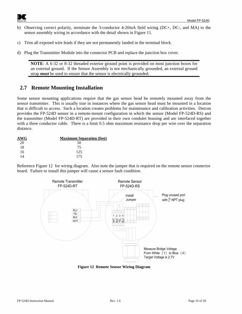
2.7 Remote Mounting Installation Some sensor mounting applications require that the gas sensor head be remotely mounted away from the sensor transmitter. This is usually true in instances where the gas sensor head must be mounted in a location that is difficult to access. Such a location creates problems for maintenance and calibration activities. Detcon provides the FP-524D sensor in a remote-mount configuration in which the sensor (Model FP-524D-RS) and the transmitter (Model FP-524D-RT) are provided in their own condulet housing and are interfaced together with a three conductor cable. There is a limit 0.5 ohm maximum resistance drop per wire over the separation distance. AWG Maximum Separation (feet) 20 50 18 75 16 125 14 175 Reference Figure 12 for wiring diagram. Also note the jumper that is required on the remote sensor connector board. Failure to install this jumper will cause a sensor fault condition.
Figure 12 Remote Sensor Wiring Diagram

Model FP-524D
FP-524D Instruction Manual Rev. 1.6 Page 11 of 39
2.7.1 Bridge Voltage Adjustment When a sensor is remote mounted, consideration must be given to the lengths of cable used and how it affects the sensor bridge voltage. Differing lengths of cables will have varying amounts of resistance which will shift the sensor bridge voltage. Because of this, the bridge voltage will need to be adjusted after initial power up. This adjustment is only required after initial installation and will not be necessary thereafter, except in the event of replacement of the plug-in sensor. Refer to section 3.5.5 to perform this adjustment.
NOTE: Refer to section 3.5.5 to set the sensor bridge voltage.
2.8 Initial Start Up Upon completion of all mechanical mounting and termination of all field wiring, apply system power in the range of 12-28VDC (24VDC typical) and observe the following normal conditions: a) FP-524D display reads “0”, and no fault messages are flashing. b) A temporary upscale reading may occur as the sensor heats up. This upscale reading will decrease to “0”
% within 1-2 minutes of power-up, assuming there is no gas in the area of the sensor.
NOTE: The 4-20mA signal is held constant at 4mA for the first two minutes after power up. Initial Operational Tests
After a warm up period of 1 hour, the sensor should be checked to verify sensitivity to combustible gas. Material Requirements
-Detcon PN 600-610000-000 Splash Guard with integral Cal Port -OR- -Detcon PN 943-000006-038 Threaded Calibration Adapter
- Detcon PN 942-520124-050 Span Gas; 50% LEL methane/balance Air at fixed flow rate of 200-500cc/min.
NOTE: Do not use calibration gases in Nitrogen background gas mixtures. This will cause significant reading inaccuracies.
a) Attach the calibration adapter to the threaded sensor housing. Apply the test gas at a controlled flow rate
of 200 - 500cc/min (200cc/min is the recommended flow). Allow 1-2 minutes for the reading to stabilize. Observe that during the 1-2 minutes the display increases to a level near that of the applied calibration gas value.
b) Remove test gas and observe that the display decreases to “0”. Initial operational tests are complete. Detcon combustible gas sensors are factory calibrated prior to shipment, and should not require significant adjustment on start up. However, it is recommended that a complete calibration test and adjustment be performed 16 to 24 hours after power-up. Refer to span calibration instructions in Section 3.4.

Model FP-524D
FP-524D Instruction Manual Rev. 1.6 Page 12 of 39
3. Operation
3.1 Programming Magnet Operating Instructions The Operator Interface of the FP-524D Series gas sensors is accomplished via two internal magnetic switches located above and below the LED display (Figure 14). The two switches, labeled “PGM1” and “PGM2”, allow for complete calibration and configuration, thereby eliminating the need for area de-classification or the use of hot permits.
Figure 13 Magnetic Programming Tool
The magnetic programming tool (Figure 13) is used to operate the magnetic switches. Switch action is defined as momentary contact, 3-second hold, and 10-second hold. (Hold times are defined as the time from the point when the arrow prompt “▼” appears.) For momentary contact use, the programming magnet is briefly held over a switch location. For 3-second hold, the programming magnet is held in place over the switch location for three seconds. For 10-second hold, the programming magnet is held in place over the switch location for 10 seconds. The 3 and 10 second holds are generally used to enter calibration/program menus and save new data. The momentary contact is generally used to move between menu items and to modify set-point values. Arrows (“▼” and “▲”) are used on the LED display to indicate when the magnetic switches are activated. The location of “PGM1” and “PGM2” are shown in Figure 14.
PGM 1
PGM 2
MODEL FP-524D-HRTHOUSTON, TEXAS
FLT 1 2 CAL
MicroSafe LEL Gas SensorALM ALM
TM
Program 1
Program 2
Figure 14 Magnetic Programming Switches
NOTE: While in the Program Mode, if there is no magnetic switch interaction after 4 consecutive menu scrolls, the sensor will automatically revert to normal operating condition. While changing values inside menu items, if there is no magnet activity after 3-4 seconds the sensor will revert to the menu scroll. (Exception to this is with “Signal Output Check” mode.)

Model FP-524D
FP-524D Instruction Manual Rev. 1.6 Page 13 of 39
3.2 Operator Interface The operating interface is menu-driven via the two magnetic program switches located under the target marks of the sensor housing. The two switches are referred to as “PGM1” and “PGM2”. The menu list consists of three major items that include sub-menus as indicated below. (Refer to the complete Software Flow Chart.) Normal Operation
Current Reading and Fault Status
Calibration Mode
AutoZero AutoSpan
Program Mode
View Sensor Status
Sensor Model Type Current Software Version Range of Detection AutoSpan Level Days Since Last AutoSpan Remaining Sensor Life Sensor Bridge Current Sensor Bridge Voltage Gas Factor Cal Factor mA Output Input Voltage Supply Sensor Temperature Alarm 1 Level Alarm 1 Ascending Alarm 1 Latching Alarm 2 Level Alarm 2 Ascending Alarm 2 Latching Fault Latching
Set AutoSpan Level Set Gas Factor Set Cal Factor Set Bridge Voltage Signal Output Check Restore Default Settings Alarm 1 Settings Alarm 2 Settings Fault Settings

Model FP-524D
FP-524D Instruction Manual Rev. 1.6 Page 14 of 39
Software Flowchart
dec
PGM1/2 (M)
mA Output XX.XX
Sensor Temp XX C
Voltage XX.X VDC
Gas Factor
Sensor Life XXX%
Bridge Current
Bridge Voltage
PGM1/2 (3)
PGM1 (3)PGM1 (3)
PGM2 (3)
Version X.XX
AutoSpan @ XX
Range XXX ppm
Last Cal XX Days
inc
Auto Time-OutView Sensor Status
PGM1/2 (3)PGM1/2 (M)
Model Type
PGM2 (3)
PGM1 (S)
PGM1/2 (3)PGM2 (S)
Auto Time-OutSet Cal Factor
##
AutoTime-out
PGM1/2 (3)PGM1/2 (M)
Set AutoSpan Level
Calibration Mode(Auto Span)
Normal Operation
PGM1/2 (M)PGM1/2 (M)
Simulation
PGM2 (10) PGM1/2 (10)
Signal Output CheckAuto Time-Out
Auto Time-Out
Auto Time-OutSet Bridge Voltage
inc
PGM1/2 (3)PGM2 (S)PGM1 (S)
#.##
PGM1/2 (3)PGM1/2 (M)
Set Gas Factor
dec
PGM1/2 (M)
Defaults Restored
PGM1/2 (10)
Restore DefaultsAuto Time-Out
PGM1/2 (3)inc
PGM1/2 (3)PGM2 (S)PGM1 (S)
##
dec
inc
PGM1/2 (3)PGM2 (S)PGM1 (S)
#.##
dec
Calibration Mode(Auto Zero)
Cal Factor
LEGEND:
PGM1 - Program Switch Location #1PGM2 - Program Switch Location #2
inc - Increasedec - Decrease#, ##, ### - numeric values
Auto Time-Out
incPGM1/2 (3)PGM1/2 (M)
Auto Time Out
Alarm 1 Ascending
PGM1/2 (3)PGM1/2 (M)
Alarm 1 Level
inc##
dec
Y/N
incPGM1/2 (3)PGM1/2 (M)
Auto Time Out
Alarm 1 LatchingY/N
Auto Time-Out
incPGM1/2 (3)PGM1/2 (M)
Auto Time Out
Alarm 1 Ascending
PGM1/2 (3)PGM1/2 (M)
Alarm 1 Level
inc##
dec
Y/N
incPGM1/2 (3)PGM1/2 (M)
Auto Time Out
Alarm 1 LatchingY/N
incPGM1/2 (3)PGM1/2 (M)
Auto Time Out
Dault LatchingY/N
(S) - Momentary Swipe.(M) - Momentary hold of Magnet during textscroll until the ">" appears, then release.(3) - 3 second hold from ">" prompt.(10) - 10 second hold from ">" prompt.Auto Time-out - 5 seconds.
Alarm 1 Level
Alarm 1 Latching
Alarm 1 Ascending
Alarm 2 Level
Alarm 2 Latching
Alarm 2 Ascending
Fault Latching
Figure 15 FP-524D Software Flowchart

Model FP-524D
FP-524D Instruction Manual Rev. 1.6 Page 15 of 39
3.3 Normal Operation In normal operation, the display continuously shows the current sensor reading, which will normally appear as “0”. Once every minute, the LED display will flash the sensor’s units of measure and the gas type (i.e.”% LEL”). If the sensor is actively experiencing any diagnostic faults, a “Fault Detected” message will scroll across the display on the display once every minute instead of the units of measure and the gas type. At any time, while the sensor is in “Fault Detected” mode, PGM1 or PGM2 can be swiped to prompt the sensor to display a list of the active faults. In normal operation, the 4-20mA current output linearly corresponds with the full-scale range.
3.4 Calibration Mode (AutoZero and AutoSpan) Calibration Mode allows for sensor span calibration. Span calibration should be performed on a routine basis (quarterly minimum) to ensure reliable performance. If a sensor has been exposed to any de-sensitizing gases or to very high over-range combustible gas levels, then a re-calibration should be considered. Unless otherwise specified, span adjustment is recommended at 50% LEL. This function is called “AUTO SPAN.”
3.4.1 AutoZero The AutoZero function is used to zero the sensor. Local ambient air can be used to zero calibrate the sensor as long as it can be confirmed that it contains no combustible gases. If this cannot be confirmed then a zero air cylinder should be used. Material Requirements: -Detcon PN 327-000000-000 MicroSafe™ Programming Magnet -Detcon PN 613-120000-000 Splash Guard with integral Cal Port -OR-
-Detcon PN 943-000006-132 Threaded Calibration Adapter -Detcon PN 942-001123-000 Zero Air cal gas or use ambient air if no combustible gas is present.
NOTE: The zero gas source should have a normal background concentration of 20.9% O2. Pure Nitrogen gas standards should not be used or errors may result.
a) If the ambient air is known to contain no combustible gas content, then it can be used to zero calibrate. If
a zero gas cal cylinder is going to be used, then attach the calibration adapter, set flow rate of 200-500cc/min, and let sensor purge for 1-2 minutes before executing the AutoZero.
b) From Normal Operation, enter Calibration Mode by holding the programming magnet over PGM1 for 3-4
seconds. Note, the “▲” prompt will show that the magnetic switch is activated during the 3-second hold period. The display will then scroll “PGM1=Zero …PGM2=Span”. Hold the programming magnet over PGM1 for 3-4 seconds once the “▲” prompt appears to execute AutoZero (or allow to timeout in 10 seconds if AutoZero is not desired).
NOTE: Upon entering Calibration Mode, the 4-20mA signal drops to 2mA and is held at this level until the program returns to normal operation.
c) The transmitter will display the following sequence of text messages as it proceeds through the AutoZero
sequence: Zero Cal . . . Setting Zero . . . Zero Saved (each will scroll twice)
d) Remove the zero gas and calibration adapter, if applicable.
Model FP-524D
FP-524D Instruction Manual Rev. 1.6 Page 16 of 39
3.4.2 AutoSpan
Material Requirements:
-Detcon PN 327-000000-000 MicroSafe™ Programming Magnet - Detcon PN 613-120000-000 Splash Guard with integral Cal Port -OR-
-Detcon PN 943-000006-132 Threaded Calibration Adapter -Detcon PN 942-520124-050 50% LEL Methane in balance air (recommended) or other suitable span gas containing a certified level of % LEL concentration of combustible gas in air balance. A flow fixed rate of 200-500cc/min is recommended.
NOTE 1: Before performing AutoSpan Calibration, verify that the AutoSpan level matches the span calibration gas concentration as described in Section 3.5.2 Set AutoSpan Level.
NOTE 2: The span gas source must have a normal background concentration of 20.9% O2. Pure Nitrogen background mixtures are not acceptable! Significant span calibration inaccuracies will result.
NOTE 3: If the target gas is other than methane, use the appropriate Gas Factor as described in Section 3.5.3 Set Gas Factor
NOTE 4: To maintain the CSA certification, it must be calibrated on methane.
CAUTION: Verification that the calibration gas level setting matches the calibration span gas concentration is required before executing “AutoSpan” calibration. These two numbers must be equal.
AutoSpan consists of entering Calibration Mode and following the menu-displayed instructions. The display will ask for the application of span gas in a specific concentration. This concentration must be equal to the calibration gas level setting. The factory default setting and recommendation for span gas concentration is 50% LEL. If a span gas containing the recommended concentration is not available, other concentrations may be used as long as they fall between 5% and 95% LEL. However, any alternate span gas concentration value must be programmed via the “Set AutoSpan Level” menu before proceeding with AutoSpan calibration. Follow the instructions “a” through “e” below for AutoSpan calibration. a) Verify that the AutoSpan Level is equal to the calibration span gas concentration. (Refer to View Sensor
Status in Section 3.5.1.) If the AutoSpan Level is not equal to the calibration span gas concentration, adjust the AutoSpan Level as instructed in Section 3.5.2 Set AutoSpan Level.
b) From Normal Operation, enter Calibration Mode by holding the programming magnet over PGM1 for 3-4
seconds. Note, the “▲” prompt will show that the magnetic switch is activated during the 3-4 second hold period. The display will then scroll “PGM1=Zero…PGM2=Span”. Hold the programming magnet over PGM2 for 3-4 seconds once the “▼” prompt appears, until the display starts to scroll “Span Cal” to execute AutoSpan (or allow to timeout in 5 seconds if AutoSpan is not desired). The display will then scroll “Apply XX % LEL” (where XX is the AutoSpan Level).
NOTE: Upon entering Calibration Mode, the 4-20mA signal drops to 2mA and is held at this level until the program returns to normal operation.
c) Apply the span calibration test gas at a flow rate of 200-500cc/min (200cc/min is the recommended flow
rate). As the sensor signal begins to increase, the display will switch to reporting a flashing “XX” reading

Model FP-524D
FP-524D Instruction Manual Rev. 1.6 Page 17 of 39
as the display shows the sensor’s “as found” response to the span gas presented. If it fails to meet the minimum in-range signal change criteria within 2½ minutes, the display will report “Range Fault” twice and the sensor will return to normal operation, aborting the AutoSpan sequence. The sensor continues to report a “Range Fault” and will not clear the fault until a successful AutoSpan is completed.
Assuming acceptable sensor signal change, after 1 minute the reading will auto-adjust to the programmed AutoSpan level. During the next 30 seconds, the AutoSpan sequence checks the sensor for acceptable reading stability. If the sensor fails the stability check, the reading is re-adjusted back to the AutoSpan level and the cycle repeats until the stability check is passed. Up to three additional 30-second stability check periods are allowed before the unit reports a “Stability Fault” twice and the sensor will return to normal operation, aborting the AutoSpan sequence. The sensor will continue to report a “Stability Fault” and will not clear the fault until a successful AutoSpan is completed. If the sensor passes the stability check, the sensor display reports a series of messages: “AutoSpan Complete” “Sensor Life XXX%” “Remove Span Gas” d) Remove the span gas and calibration adapter. The sensor will report a live reading as it clears toward “0”.
When the reading clears below 5 % LEL, the sensor will display “Span Complete” and will revert to normal operation. If the sensor fails to clear to less than 5% LEL within 5 minutes, a “Clearing Fault” will be reported twice and the sensor will return to normal operation, aborting the AutoSpan sequence. The sensor will continue to report a “Clearing Fault” and will not clear the fault until a successful AutoSpan is completed.
NOTE 1: If the sensor fails the minimum signal change criteria, a “Range Fault” will be declared and a “Fault Detected” message will be displayed alternately with the sensor’s current reading. The 4-20mA output will be taken to 0mA.
NOTE 2: If the sensor fails the stability criteria, a “Stability Fault” will be declared and a “Fault Detected” message will be displayed alternately with the sensor’s current reading. The 4-20mA output will be taken to 0mA.
NOTE 3: If the sensor fails the clearing time criteria, a “Clearing Fault” will be declared and a “Fault Detected” message will be displayed alternately with the sensor’s current reading. The 4-20mA output will be taken to 0mA.
3.5 Program Mode Program Mode provides a View Sensor Status menu to check operational and configuration parameters. Program Mode also provides for adjustment of the AutoSpan Level, Bridge Voltage, Gas Factor, and Cal Factor. Additionally, it includes the Restore Factory Defaults and Signal Output Check diagnostic functions. The Program Mode menu items appear in the order presented below:
View Sensor Status Set AutoSpan Level Set Gas Factor Set Cal Factor Set Bridge Voltage Signal Output Check Restore Default Settings

Model FP-524D
FP-524D Instruction Manual Rev. 1.6 Page 18 of 39
Alarm 1 Settings Alarm 2 Settings Fault Settings
Navigating Program Mode
From Normal Operation, enter Program Mode by holding the magnet over PGM2 for 4 seconds (until the displays starts to scroll “View Sensor Status”). Note, the “▼” prompt will show that the magnetic switch is activated during the 4 second hold period. The sensor will enter Program Mode and the display will display the first menu item “View Sensor Status”. To advance to the next menu item, hold the magnet over PGM1 or PGM2 while the current menu item’s text is scrolling. At the conclusion of the text scroll, the arrow prompt (“▼” for PGM2 or “▲” for PGM1) will appear, immediately remove the magnet. The display will advance to the next menu item. Repeat this process until the desired menu item is displayed. Note, PGM1 moves the menu items from right to left and PGM2 moves the menu items from left to right. To enter a menu item, hold the magnet over PGM1 or PGM2 while the menu item is scrolling. At the conclusion of the text scroll the “▼”prompt (“▼” for PGM2 or “▲” for PGM1) will appear, continue to hold the magnet over PGM1 or PGM2 for an additional 3-4 seconds to enter the selected menu item. If there is no magnet activity while the menu item text is scrolling (typically 4 repeated text scrolls), the sensor will automatically revert to Normal Operation.
3.5.1 View Sensor Status View Sensor Status displays all current configuration and operational parameters including: sensor type, software version number, detection range, AutoSpan level, days since last AutoSpan, estimated remaining sensor life, bridge current, bridge voltage, gas factor, cal factor, mA output, input voltage, and sensor ambient temperature. From the View Sensor Status text scroll, hold the magnet over PGM1 or PGM2 until the “▼” prompt appears and continue to hold the magnet in place for an additional 3-4 seconds (until the display starts to scroll “Status Is”). The display will scroll the complete list of sensor status parameters sequentially: Sensor Model Type
The menu item appears as: “FP-524D” Current Software Version
The menu item appears as: “V X.XXZ5” Range of Detection
The menu item appears as: “Range XXX” AutoSpan Level
The menu item appears as: “Auto Span Level XX” Days Since Last AutoSpan
The menu items appears as: “Last Cal XX days” Remaining Sensor Life
The menu item appears as: “Sensor Life XXX%”
Model FP-524D
FP-524D Instruction Manual Rev. 1.6 Page 19 of 39
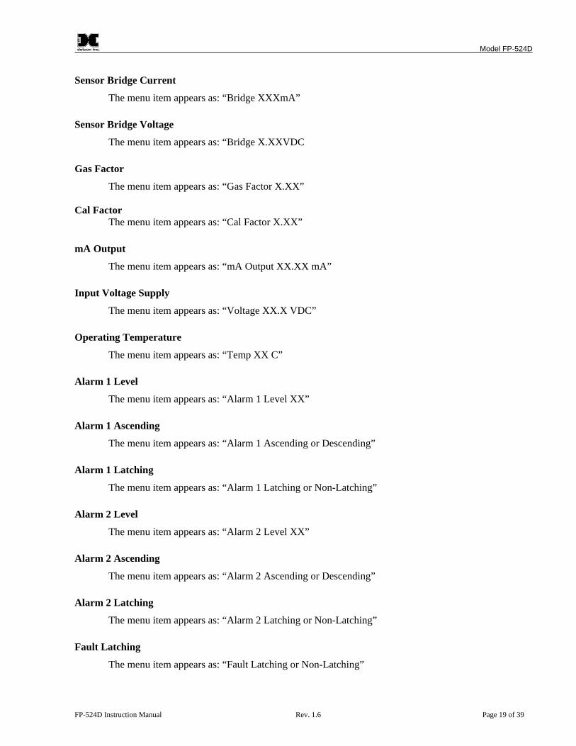
Sensor Bridge Current
The menu item appears as: “Bridge XXXmA” Sensor Bridge Voltage
The menu item appears as: “Bridge X.XXVDC Gas Factor
The menu item appears as: “Gas Factor X.XX”
Cal Factor The menu item appears as: “Cal Factor X.XX”
mA Output
The menu item appears as: “mA Output XX.XX mA” Input Voltage Supply
The menu item appears as: “Voltage XX.X VDC” Operating Temperature
The menu item appears as: “Temp XX C”
Alarm 1 Level
The menu item appears as: “Alarm 1 Level XX” Alarm 1 Ascending
The menu item appears as: “Alarm 1 Ascending or Descending” Alarm 1 Latching
The menu item appears as: “Alarm 1 Latching or Non-Latching”
Alarm 2 Level
The menu item appears as: “Alarm 2 Level XX” Alarm 2 Ascending
The menu item appears as: “Alarm 2 Ascending or Descending” Alarm 2 Latching
The menu item appears as: “Alarm 2 Latching or Non-Latching”
Fault Latching
The menu item appears as: “Fault Latching or Non-Latching”

Model FP-524D
FP-524D Instruction Manual Rev. 1.6 Page 20 of 39
When the status list sequence is complete, the display will revert to the “View Sensor Status” text scroll. The user can either: 1) review list again by executing another 3-4 second hold, 2) move to another menu item by executing a momentary hold over PGM1 or PGM2, or 3) return to Normal Operation via automatic timeout of about 15 seconds (the display will scroll “View Sensor Status” 4 times and then return to Normal Operation).
3.5.2 Set AutoSpan Level Set AutoSpan Level is used to set the span gas concentration level that is being used to calibrate the sensor. This level is adjustable from 5% to 95% of selected full-scale range. The current setting can be viewed in View Program Status. The menu item appears as: “Set AutoSpan Level”. From the Set AutoSpan Level text scroll, hold the magnet over PGM1 or PGM2 until the “▼” prompt appears and continue to hold the magnet in place for an additional 3-4 seconds (until the display starts to scroll “Set Level”). The display will switch to “XX“(where XX is the current gas level). Swipe the magnet momentarily over PGM1 to increase or PGM2 to decrease the AutoSpan Level until the correct level is displayed. When the correct level is achieved, hold the magnet over PGM1 or PGM2 for 3-4 seconds to accept the new value. The display will scroll “Level Saved”, and revert to “Set AutoSpan Level” text scroll. Move to another menu item by executing a momentary hold, or return to Normal Operation via automatic timeout of about 15 seconds (the display will scroll “Set AutoSpan Level” 4 times and then return to Normal Operation).
3.5.3 Set Gas Factor Because of the catalytic bead sensor’s almost universal response to combustible gases, the FP-524D sensor can be configured to specifically detect any of the combustible gases listed in Table 2. This gas is referred to as the “target gas”. In addition, the sensor can also be configured so that it can be calibrated with any of the listed gases regardless of which target gas is selected. This gas is referred to as the “cal gas”. These two features, Set Gas Factor and Set Cal Factor, allow a significant degree of flexibility in the detection and span calibration process.
NOTE: The default value for gas factor is 1.0. This would be used when methane is the target gas. Values other than 1.0 would be used when the target gas is not methane.
Set Gas Factor is used to make the appropriate signal sensitivity adjustment when the target gas is a gas other than methane. This is necessary because the catalytic bead sensor has different signal strengths for each combustible gas and all reading calculations are made based on a reference to methane. The gas factor value is adjustable from 0.2 to 5.0. It represents the translation between the target gas and methane gas, where methane has a normalized gas factor = 1.0. For example, the gas factor for butane is 1.71, because the signal strength of butane is 1.71 times lower than methane. The current setting can be viewed in View Program Status – Gas Factor. The following table shows the gas factors of most combustible gases that can be measured. Find the target gas and enter the corresponding value as the gas factor. For example, if butane were the target gas, the correct gas factor would be 1.71. If there is a mixture of target gases, use a weighted approach to determine the correct gas factor. For example, if the target gas was 50% butane and 50% methane, the correct gas factor would be calculated and entered as 0.5(1.71) + 0.5 (1.0) = 1.35.

Model FP-524D
FP-524D Instruction Manual Rev. 1.6 Page 21 of 39
Table 2 Gas/Cal Factors
Gas Factor Gas Factor Gas Factor Acetaldehyde 1.66 Decane 3.05 Dimethyl Ether 1.60 Acetic Acid 1.84 Diethylamine 2.05 Methylethyl Ether 2.27 Acetic Anhydride 2.17 Dimethylamine 1.73 Methylethyl Ketone 2.42 Acetone 1.93 2,3-Dimethylpentane 2.51 Methyl Formate 1.49 Acetylene 1.76 2,2-Dimethylpropane 2.52 Methyl Mercaptan 1.64 Alkyl Alcohol 1.96 Dimethyl sulfide 2.30 Methyl propionate 1.95 Ammonia 0.79 1,4-Dioxane 2.24 Methyl n-propyl Ketone 2.46 n-Amyl Alcohol 3.06 Ethane 1.47 Naphtha 3.03 Aniline 2.54 Ethyl Acetate 1.95 Naphthalene 2.94 Benzene 2.45 Ethyl Alcohol 1.37 Nitromethane 1.72 Biphenyl 4.00 Ethylamine 1.90 n-Nonane 3.18 1,3-Butadiene 1.79 Ethyl Benzene 2.80 n-Octane 2.67 Butane 1.71 Ethylcyclopentane 2.52 n-Pentane 2.18 iso-Butane 1.93 Ethylene 1.41 iso-Pentane 2.15 Butene-1 2.20 Ethylene Oxide 1.93 Propane 1.81 cis-Butene-2 2.06 Diethyl Ether 2.16 n-Propyl Alcohol 2.12 trans-Butene-2 1.97 Ethyl Formate 2.26 n-Propylamine 2.07 n-Butyl Alcohol 2.91 Ethyl Mercaptan 1.78 Propylene 1.95 iso-Butyl Alcohol 1.89 n-Heptane 2.59 Propylene Oxide 2.18 tert-Butyl-Alcohol 1.34 n-Hexane 2.71 iso-Propyl Ether 2.29 n-Butyl Benzene 3.18 Hydrazine 2.22 Propyne 2.40 iso-Butyl Benzene 3.12 Hydrogen Cyanide 2.09 Toluene 2.47 n-Butyric Acid 2.63 Hydrogen 1.30 Triethylamine 2.51 Carbon Disulphide 5.65 Hydrogen Sulphide 2.54 Trimethylamine 2.06 Carbon Monoxide 1.32 Methane 1.00 Vinyl Chloride 2.32 Carbon Oxysulphide 1.07 Methyl Acetate 2.01 Vinyl Ethyl Ether 2.38 Cyanogen 1.12 Methyl Alcohol 1.16 o-Xylene 2.79 Cyclohexane 2.43 Methylamine 1.29 m-Xylene 2.55 Cyclopropane 1.60 Methylcyclohexane 2.26 p-Xylene 2.55
The menu item appears as: “Set Gas Factor”. From the Set Gas Factor text scroll, hold the magnet over PGM1 or PGM2 until the “▼” prompt appears and continue to hold the magnet in place for an additional 3-4 seconds (until the display starts to scroll “Set Factor”). The display will then switch to “X.XX“(where X.XX is the current gas factor). Swipe the magnet momentarily over PGM1 to increase or PGM2 to decrease the gas factor level until the correct value is displayed. Hold the magnet over PGM1 or PGM2 for 3 seconds to accept the new value. The display will scroll “Factor Saved”, and revert to “Set Gas Factor” text scroll. Move to another menu item by executing a momentary hold, or, return to Normal Operation via automatic timeout of about 15 seconds (the display will scroll “Set Gas Factor” 4 times and then return to Normal Operation).
3.5.4 Set Cal Factor Because of the catalytic bead sensor’s almost universal response to combustible gases, the FP-524D sensor can be span calibrated with any of the combustible gases listed in Table 2 above. This specific gas is referred to as the “cal gas”.
NOTE: The default value for cal factor is 1.0. This would be used when methane is the cal gas. Values other than 1.0 would be used when the span cal gas is not methane.
Model FP-524D
FP-524D Instruction Manual Rev. 1.6 Page 22 of 39
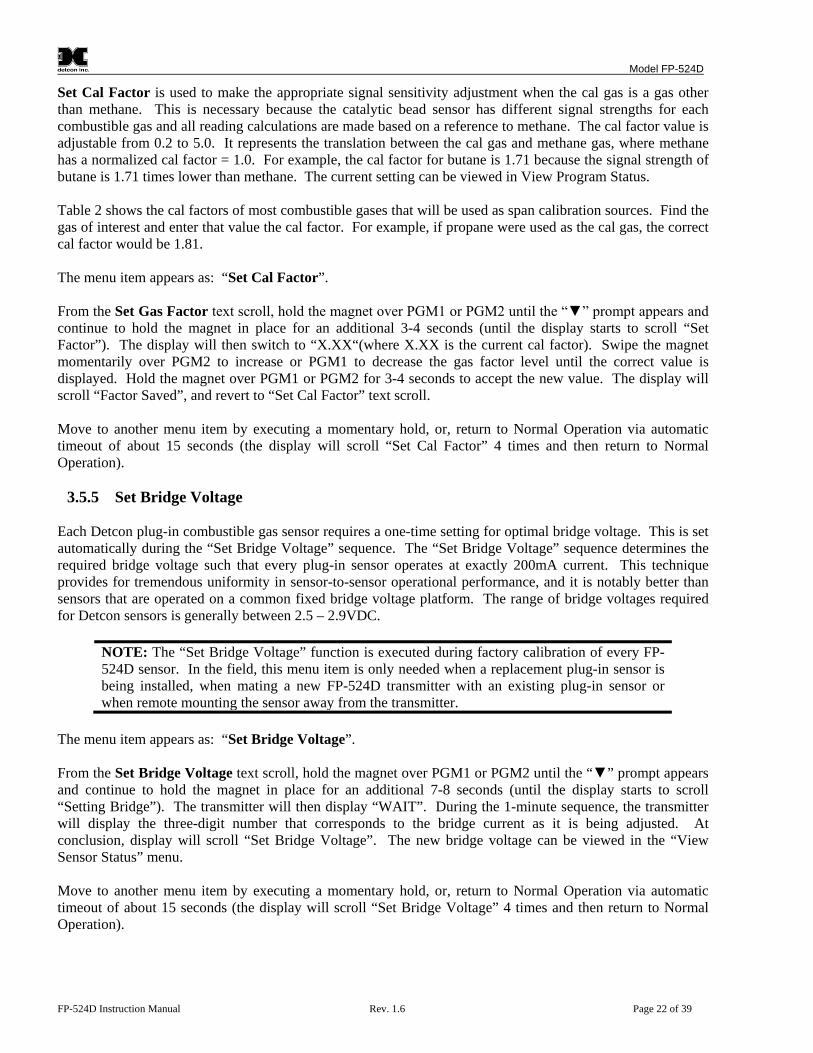
Set Cal Factor is used to make the appropriate signal sensitivity adjustment when the cal gas is a gas other than methane. This is necessary because the catalytic bead sensor has different signal strengths for each combustible gas and all reading calculations are made based on a reference to methane. The cal factor value is adjustable from 0.2 to 5.0. It represents the translation between the cal gas and methane gas, where methane has a normalized cal factor = 1.0. For example, the cal factor for butane is 1.71 because the signal strength of butane is 1.71 times lower than methane. The current setting can be viewed in View Program Status. Table 2 shows the cal factors of most combustible gases that will be used as span calibration sources. Find the gas of interest and enter that value the cal factor. For example, if propane were used as the cal gas, the correct cal factor would be 1.81. The menu item appears as: “Set Cal Factor”. From the Set Gas Factor text scroll, hold the magnet over PGM1 or PGM2 until the “▼” prompt appears and continue to hold the magnet in place for an additional 3-4 seconds (until the display starts to scroll “Set Factor”). The display will then switch to “X.XX“(where X.XX is the current cal factor). Swipe the magnet momentarily over PGM2 to increase or PGM1 to decrease the gas factor level until the correct value is displayed. Hold the magnet over PGM1 or PGM2 for 3-4 seconds to accept the new value. The display will scroll “Factor Saved”, and revert to “Set Cal Factor” text scroll. Move to another menu item by executing a momentary hold, or, return to Normal Operation via automatic timeout of about 15 seconds (the display will scroll “Set Cal Factor” 4 times and then return to Normal Operation).
3.5.5 Set Bridge Voltage Each Detcon plug-in combustible gas sensor requires a one-time setting for optimal bridge voltage. This is set automatically during the “Set Bridge Voltage” sequence. The “Set Bridge Voltage” sequence determines the required bridge voltage such that every plug-in sensor operates at exactly 200mA current. This technique provides for tremendous uniformity in sensor-to-sensor operational performance, and it is notably better than sensors that are operated on a common fixed bridge voltage platform. The range of bridge voltages required for Detcon sensors is generally between 2.5 – 2.9VDC.
NOTE: The “Set Bridge Voltage” function is executed during factory calibration of every FP-524D sensor. In the field, this menu item is only needed when a replacement plug-in sensor is being installed, when mating a new FP-524D transmitter with an existing plug-in sensor or when remote mounting the sensor away from the transmitter.
The menu item appears as: “Set Bridge Voltage”. From the Set Bridge Voltage text scroll, hold the magnet over PGM1 or PGM2 until the “▼” prompt appears and continue to hold the magnet in place for an additional 7-8 seconds (until the display starts to scroll “Setting Bridge”). The transmitter will then display “WAIT”. During the 1-minute sequence, the transmitter will display the three-digit number that corresponds to the bridge current as it is being adjusted. At conclusion, display will scroll “Set Bridge Voltage”. The new bridge voltage can be viewed in the “View Sensor Status” menu. Move to another menu item by executing a momentary hold, or, return to Normal Operation via automatic timeout of about 15 seconds (the display will scroll “Set Bridge Voltage” 4 times and then return to Normal Operation).

Model FP-524D
FP-524D Instruction Manual Rev. 1.6 Page 23 of 39
3.5.6 Signal Output Check Signal Output Check provides a simulated 4-20mA output. This simulation allows the user to conveniently perform a functional system check of their entire safety system. This signal output simulation also aids the user in performing troubleshooting of signal wiring problems. The menu item appears as: “Signal Output Check”. From the “Signal Output Check” text scroll, hold the magnet over PGM1 or PGM2 until the “▼” prompt appears and then hold continuously for an additional 10 seconds. Once initiated, the display will scroll “Simulation Active” until the function is stopped. During simulation mode, the 4-20mA value will be increased from 4.0mA to 20.0mA (in 1% of range increments at about a 1 second update rate) and then decreased from 20.0mA to 4.0mA.
NOTE: Signal Output Check stays active indefinitely until the user stops the function. There is no automatic timeout for this feature.
To end simulation mode, hold magnet over PGM1 or PGM2 for 3 seconds. The display will either move to the prior menu item or move to the next menu item respectively. Move to another menu item by executing a momentary hold, or, return to Normal Operation via automatic timeout of about 15 seconds.
3.5.7 Restore Factory Defaults Restore Factory Defaults is used to clear current user configuration and calibration data from memory and revert to factory default values. This may be required if the settings have been configured improperly and a known reference point needs to be re-established to correct the problem. This menu item appears as: “Restore Defaults”.
NOTE: “Restoring Factory Defaults” should only be used when absolutely necessary. All previously existing configuration inputs will have to be re-entered if this function is executed. A full 10-second magnet hold on PGM 1 is required to execute this function.
From the “Restore Defaults” text scroll, hold the programming magnet over PGM1 until the “▲” prompt appears and continue to hold 10 seconds. The display will scroll “Restoring Defaults”, and then will revert to the “Restore Defaults” text scroll. Move to another menu item by executing a momentary hold, or, return to Normal Operation via automatic timeout of about 15 seconds (the display will scroll “Restore Defaults” 4 times and then return to Normal Operation). Following the execution of “Restore Defaults”, the FP-524D will revert to its factory default settings. The default settings are:
NOTE: The following must be performed in order before the sensor can be placed back into operation.
AutoSpan Level = 50 %LEL. AutoSpan level must be set appropriately by the operator (Section 3.5.2). Gas Factor = 1.0. The Gas Factor must be set appropriately by the operator (Section 3.5.3). Cal Factor = 1.0. The Cal Factor must be set appropriately by the operator (Section 3.5.4). AutoZero: AutoZero Settings are lost and user must perform new AutoZero (Section 3.4.1). AutoSpan: AutoSpan Settings are lost and user must perform new AutoSpan (Section 3.4.2).

Model FP-524D
FP-524D Instruction Manual Rev. 1.6 Page 24 of 39
3.5.8 Alarm 1 and 2 Settings The FP-524D has the ability to set alarm levels that are displayed on the front of the sensor via the LED’s ALM 1 and ALM 2. These alarm LEDs can be set as latching or non-latching. In non-latching mode, the LED is deactivated as soon as the sensor alarm condition is cleared. In latching mode, the LED remains active even after the alarm condition has cleared. Once activated, the LED can only be deactivated by swiping a magnetic programming tool above the PGM1 or PGM2 mark on the FP-524D face plate. The alarm LEDs can be configured for ascending or descending mode. In ascending mode the LED will be activated when the concentration is above the alarm threshold. This is the most common mode of operation for the FP-524D. The alarm LEDs can also be activated in descending mode. In this mode, the alarm LEDs will activate when the concentration is below the alarm threshold. The menu item appears as: “Alarm X Settings” From the “Alarm X Settings” text scroll, hold the programming magnet over PGM1 or PGM2 until the “▼” prompt appears and continue to hold the magnet in place for an additional 3-4 seconds (until the display starts to scroll “Set Level”). The display will then switch to “XXX“(where XXX is the current alarm level in ppm). Swipe the magnet momentarily over PGM2 to decrease or PGM1 to increase the alarm level until the desired level is displayed. Hold the magnet over PGM1 or PGM2 for 3 seconds to accept the new value (until the display starts to scroll “Level Saved”). The display will scroll “Set Ascending”, and then switch to “Yes” or “No”. “Yes” indicates the LED is in ascending mode and “No” indicates the LED is in descending mode. Swipe the magnet momentarily over PGM2 or PGM1 until the correct value is displayed. Hold the magnet over PGM1 or PGM2 for 3 seconds to accept the new value. The display will scroll “Set Latching”, and then switch to “Yes” or “No”. “No” indicates the LED is non-latching and “Yes” indicates the LED is latching. Swipe the magnet momentarily over PGM2 or PGM1 until the correct value is displayed. Hold the magnet over PGM1 or PGM2 for 3 seconds to accept the new value. Hold the magnet over PGM1 or PGM2 for 3 seconds to accept the new value (until the display starts to scroll “Saved”). Move to another menu item by executing a momentary hold, or, return to Normal Operation via automatic timeout of about 15 seconds (the display will scroll “Alarm X Settings” 4 times and then return to Normal Operation). 3.5.9 Fault Settings The FP-524D Fault LED can be configured to change state when the sensor experiences a fault condition. This LED can be configured as either latching or non-latching. In non-latching mode, the LED is deactivated as soon as the fault condition is cleared. In latching mode, the LED remains active even after the fault condition has cleared. Once activated, the LED can only be deactivated by swiping a magnetic programming tool above the PGM1 or PGM2 mark on the TP-524D face plate. The menu item appears as: “Fault Settings” From the “Fault Settings” text scroll, hold the programming magnet over PGM1 or PGM2 until the “▼” prompt appears and continue to hold the magnet in place for an additional 3-4 seconds. The display will scroll “Set Latching”, and then switch to “Yes” or “No”. “No” indicates the relay is non-latching and “Yes” indicates the relay is latching. Swipe the magnet momentarily over PGM2 or PGM1 until the correct value is displayed. Hold the magnet over PGM1 or PGM2 for 3 seconds to accept the new value.

Model FP-524D
FP-524D Instruction Manual Rev. 1.6 Page 25 of 39
Hold the magnet over PGM1 or PGM2 for 3 seconds to accept the new value (until the display starts to scroll “Saved”). Move to another menu item by executing a momentary hold, or, return to Normal Operation via automatic timeout of about 15 seconds (the display will scroll “Fault Settings” 4 times and then return to Normal Operation).
3.6 Program Features Detcon FP-524D combustible gas sensors incorporate a comprehensive set of diagnostic features to achieve Fail-Safe Operation. These Operational features and Failsafe Diagnostic features are detailed below.
3.6.1 Operational Features Over-Range
When gas greater than the full-scale range is detected, the sensor display will continuously flash the full-scale reading of 100. This designates an over-range condition. The 4-20mA signal will report a 22mA output during this time. In-Calibration Status
When the sensor is engaged in AutoZero or AutoSpan calibration, the 4-20mA output signal is taken to 2.0mA. This alerts the user that the sensor is not in an active measurement mode. This feature also allows the user to log the AutoZero and AutoSpan events via their master control system. Sensor Life
Sensor Life is calculated after each AutoSpan calibration and is reported as an indicator of remaining service life. It is reported in the “View Sensor Status” menu. Sensor Life is reported on a scale of 0-100%. When Sensor Life falls below 25%, the sensor cell should be replaced within a reasonable maintenance schedule. Last AutoSpan Date
This reports the number of days that have elapsed since the last successful AutoSpan. This is reported in the View Sensor Status menu. After 180 days, an AutoSpan Fault will be declared.
3.6.2 Fault Diagnostic/Failsafe Features Fail-Safe/Fault Supervision
Model FP-524D MicroSafe™ sensors are designed for Fail-Safe operation. If any of the diagnostic faults listed below are active, the sensor display will scroll the message “Fault Detected” every 60 seconds during normal operation. At any time during “Fault Detected” mode, holding the programming magnet over PGM1 or PGM2 for 1 second will display the active fault(s). All active faults are reported sequentially. Most fault conditions result in failed operation of the sensor. In these cases the 4-20mA signal is dropped to the universal fault level of 0mA. These include the AutoZero and AutoSpan Calibration faults, Sensor Faults, Processor Fault, Memory Fault, Loop Fault, and Input Voltage Fault. (The 0mA fault level is not employed for a Temperature Fault, or during Calibration.)
NOTE: Refer to the Troubleshooting Guide, Section 5, for guidance on fault conditions.

Model FP-524D
FP-524D Instruction Manual Rev. 1.6 Page 26 of 39
Zero Fault
If the sensor drifts below –10% LEL, the “Zero Fault” will be declared. A “Zero Fault” will cause a “Fault Detected” message to scroll once a minute on the transmitter display and drop the 4-20mA output to 0mA. The sensor should be considered “Out-of-Service” until a successful AutoZero calibration is performed. Range Fault – AutoSpan
If the sensor fails the minimum signal change criteria during AutoSpan sequence (Section 3.4), the “Range Fault” will be declared. A “Range Fault” will cause a “Fault Detected” message to scroll once a minute on the sensor display and drop the 4-20mA output to 0mA. The sensor should be considered “Out-of-Service” until a successful AutoSpan calibration is performed. Stability Fault - AutoSpan
If the sensor fails the signal stability criteria during AutoSpan sequence (Section 3.4), the “Stability Fault” will be declared. A “Stability Fault” will cause a “Fault Detected” message to scroll once a minute on the sensor display and drop the mA output to 0mA. The sensor should be considered as “Out-of-Service” until a successful AutoSpan calibration is performed. Clearing Fault - AutoSpan
If the sensor fails the signal stability criteria during AutoSpan sequence (Section 3.4), the “Clearing Fault” will be declared. A “Clearing Fault” will cause a “Fault Detected” message to scroll once a minute on the sensor display and drop the mA output to 0mA. The sensor should be considered as “Out-of-Service” until a successful AutoSpan calibration is performed. Sensor Current Fault
If the current through the sensor bridge (See Figure 3) drifts outside the range of 200mA ± 50mA, a “Sensor Current Fault” will be declared. A “Sensor Current Fault” will cause a “Fault Detected” message to scroll once a minute on the transmitter display. If a Sensor Current Fault occurs, the 4-20mA signal will be set at 0mA until the fault condition is resolved. Sensor Voltage Fault If the voltage across the sensor bridge (See Figure 3) is greater than 3.5VDC or less than 1.8VDC, a “Sensor Voltage Fault” will be declared. A “Sensor Voltage Fault” will cause a “Fault Detected” message to scroll once a minute on the transmitter display. If a Sensor Voltage Fault occurs, the 4-20mA signal will be set at 0mA until the fault condition is resolved. Processor Fault
If the detector has any unrecoverable run-time errors, a “Processor Fault” is declared. A “Processor Fault” will cause a “Fault Detected” message to scroll once a minute on the sensor display. If a Processor Fault occurs, the 4-20mA signal will be set at 0mA until the fault condition is resolved. Memory Fault
If the detector has a failure in saving new data to memory, a “Memory Fault” is declared. A “Memory Fault” will cause the “Fault Detected” message to scroll once a minute on the sensor display. If a Memory Fault occurs, the 4-20mA signal will be set at 0mA until the fault condition is resolved.

Model FP-524D
FP-524D Instruction Manual Rev. 1.6 Page 27 of 39
4-20mA Loop Fault
If the sensor detects a condition where the 4-20mA output loop is not functional (high loop resistance or failed circuit function) a “4-20mA Fault” is declared. A “4-20mA Fault” will cause the “Fault Detected” message to scroll once a minute on the ITM display. If a Loop Fault occurs, the 4-20mA signal will be set at 0mA until the fault condition is resolved. If the 4-20mA current loop is still out of tolerance, contact Detcon at [email protected], or contact Detcon customer service. Input Voltage Fault
If the detector is currently receiving an input voltage that is outside of the 11.5-28VDC range, an “Input Voltage Fault” is declared. An “Input Voltage Fault” will cause the “Fault Detected” message to scroll once a minute on the sensor display. If an Input Voltage Fault occurs, the 4-20mA signal will be set at 0mA until the fault condition is resolved. Temperature Fault
If the detector is reporting currently an ambient temperature that is outside of the –40ºC to +75ºC range, a “Temperature Fault” is declared. A “Temperature Fault” will cause the “Fault Detected” message to scroll once a minute on the sensor display. If a Temperature Fault occurs, the 4-20mA signal remains operational. AutoSpan Fault
If 180 days has elapsed since the last successful AutoSpan, an AutoSpan Fault will be generated. An “AutoSpan Fault” will cause the “Fault Detected” message to scroll once a minute on the sensor display. If an AutoSpan Reminder Fault occurs, the 4-20mA signal remains operational.

Model FP-524D
FP-524D Instruction Manual Rev. 1.6 Page 28 of 39
4. Service and Maintenance Calibration Frequency
In most applications, quarterly to biannual zero and span calibration intervals will assure reliable detection. However, industrial environments differ. Upon initial installation and commissioning, close frequency tests should be performed, weekly to monthly. Test results should be recorded and reviewed to determine a suitable calibration interval. Visual Inspection
The Sensor should be inspected annually. Inspect for signs of corrosion, pitting, and water damage. During visual inspection, the Splash Guard should be inspected to insure that it is not blocked. Examine the porous 316SS flame arrestor within the sensor’s bottom housing for signs of physical blockage or severe corrosion. Also, inspect inside the Junction Box for signs of water accumulation or terminal block corrosion. Condensation Prevention Packet
A moisture condensation packet should be installed in every explosion proof junction box. The moisture condensation prevention packet will prevent the internal volume of the J-Box from condensing and accumulating moisture due to day-night humidity changes. This packet provides a critical function and should be replaced annually. Detcon’s PN is 960-202200-000. Replacement of Combustible Gas Sensor
NOTE: It is necessary to remove power while changing the combustible gas sensor in order to maintain area classification while the junction box cover is removed. Proper “Hot Permits” may apply.
a) Remove the junction box cover and remove the Transmitter Module from the Connector PCB. b) Unthread the lower half of the sensor housing. The lower housing includes two recessed holes for a
spanner wrench if needed. c) Gently pull on the combustible gas cell to unplug it from the upper housing. d) Orient the new plug-in sensor so that it matches with the female connector pins, and plug into the
upper housing. e) Thread the lower housing back into the upper housing and tighten using a spanner wrench. f) Perform “Set Bridge Voltage” (Section 3.5.5) to match the new combustible gas sensor with the
Transmitter Module. g) Perform a successful AutoZero and AutoSpan to match the new combustible gas sensor with the
Transmitter Module (Section 3.4). Replacement of Transmitter Module
a) Remove the junction box cover and unplug the Transmitter Module from the Connector PCB.
NOTE: It is necessary to remove power to the junction box while changing the transmitter module in order to maintain area classification.
b) Plug the new Transmitter Module into the connector PCB, and reinstall the junction box cover. c) Perform Set Bridge Voltage and Set AutoSpan Level and then perform a successful AutoZero and AutoSpan before placing sensor assembly into operation.

Model FP-524D
FP-524D Instruction Manual Rev. 1.6 Page 29 of 39
Replacement of the Connector PCB
NOTE: It is necessary to remove power to the junction box while changing the connector PCB in order to maintain area classification.
a) Remove the junction box cover and remove the transmitter module from the connector PCB. b) Remove the black, white, blue, and yellow wires coming from the combustible gas sensor from the connector PCB. c) Remove the output wiring from the connector PCB terminals labeled DC+, DC-, and MA. d) Remove the two 6-32 screws holding the Connector PCB to the base of the junction box, and remove the connector PCB. e) Install the new connector PCB using the two 6-32 screws removed in step d). f) Re-connect the output wiring to the terminals labeled DC+, DC-, and MA on the connector PCB, g) Reconnect the black, white, blue, and yellow wires from the combustible gas sensor to the connector PCB. h) Reinstall the transmitter module, and the junction box cover.

Model FP-524D
FP-524D Instruction Manual Rev. 1.6 Page 30 of 39
5. Troubleshooting Guide Refer to the list of failsafe diagnostic features listed in Section 3.6.2 for additional reference in troubleshooting activities. Listed below are some typical trouble conditions and their probable cause and resolution path.
Figure 16 Replaceable Combustible Gas Sensor
Sensor Current/Voltage Fault
Probable Cause: Plug-in sensor has failed Remove plug-in sensor and verify resistance between PIN 5 and PIN 7 and PIN 2 and PIN 4 using an ohmmeter. At room temperature, the normal reading range should be 2.5-3.5 ohms for both catalytic beads. Replace plug-in sensor if either measurement is open circuit or significantly out-of range. Zero Fault
Probable Causes: Plug-in sensor has drifted Perform AutoZero calibration per Section 3.4.1 Replace the plug-in sensor. AutoSpan Calibration Faults – (Range, Stability, and Clearing)
To clear any AutoSpan Calibration fault, the AutoSpan process must be completed successfully (Section3.4). Range Fault
Probable Causes: Failed sensor, cal gas not applied or not applied at appropriate time, or problems w/ cal gas and delivery Check bridge voltage (should be 2.7 +/- 0.2VDC). Check validity of span gas and flow rate (check MFG date on cal cylinder). Make sure correct cal factor is set Check for obstructions through stainless steel sinter element (including being wet). Replace the plug-in sensor. Stability Fault
Probable Causes: Failed sensor, empty or close to empty cal gas cylinder, or problems w/ cal gas and delivery Check bridge voltage (should be 2.7 +/- 0.2VDC). Check validity of span gas and flow rate (check MFG date on cal cylinder). Make sure correct cal factor is set Check for obstructions through stainless steel sinter element (including being wet). Replace the plug-in sensor. Clearing Fault

Model FP-524D
FP-524D Instruction Manual Rev. 1.6 Page 31 of 39
Probable Causes: Failed sensor, cal gas not removed at appropriate time, problems w/ cal gas and delivery, or Background combustible gases preventing clearing Confirm that no combustible gasses are present in background. Check bridge voltage (should be 2.7 +/- 0.2VDC). Check validity of span gas and flow rate (check MFG date on cal cylinder). Make sure correct cal factor and gas factor is set Check for obstructions through stainless steel sinter element (including being wet). Replace the plug-in sensor. Poor Calibration Repeatability
Probable Causes: Failed sensor, use of wrong cal gas, problems w/ cal gas and delivery, or poison or inhibitor gases Check for adequate sensor life. Check bridge voltage (should be 2.7 +/- 0.2VDC). Check validity of span gas and flow rate (check MFG date on cal cylinder). Check for obstructions through stainless steel sinter element (including being wet). Evaluate area for presence of poisoning or inhibiting gases as listed in Section 2.3. Increase calibration frequency. Note the sensor’s serial # and report repetitive problems to Detcon’s Repair Department. Replace plug-in sensor. Unstable Output/ Sudden spiking
Possible Causes: Unstable power supply, inadequate grounding, or inadequate RFI protection Verify power source is stable. Verify field wiring is properly shielded and grounded. Contact Detcon to optimize shielding and grounding. Add Detcon’s RFI Protection Circuit accessory if problem is proven RFI induced. Nuisance Alarms
Check condulet for accumulated water and abnormal corrosion on terminal blocks. If nuisance alarms are happening at night, suspect condensation in condulet. Add or replace Detcon’s Condensation Prevention Packet P/N 960-202200-000. Investigate the presence of other target gases that are causing cross-interference erroneous readings. Determine if cause is RFI induced. Processor and/or Memory Faults
Recycle power in attempt to clear problem Restore factory defaults - This will clear the processor’s memory and may correct problem. Remember to re-enter all customer settings for range and cal gas level after Restore Factory Defaults. If problem persists, replace the plug-in transmitter module. Unreadable Display
If due to excessive sunlight, install a sunshade to reduce glare. Nothing Displayed – Transmitter not Responding
Verify condulet has no accumulated water or abnormal corrosion. Verify required DC power is applied to correct terminals. Swap with a known-good transmitter module to determine if transmitter module is faulty.

Model FP-524D
FP-524D Instruction Manual Rev. 1.6 Page 32 of 39
Faulty 4-20mA Output
If sensor has a normal reading with no faults displayed, and the 4-20 mA signal output is 0mA…. Check that wiring is properly connected at terminal blocks and through to controller inputs. The 4-20mA output loop must be closed (resistance of < 1000 ohms) to avoid the Loop Fault. Perform a “Signal Output Check” sequence via Section 3.5.6 and verify 4-20mA output with current meter. Swap with a known-good transmitter module to determine if the transmitter module’s 4-20mA output circuit is faulty. If the 4-20mA current loop is still out of tolerance, contact Detcon at [email protected], or contact Detcon customer service.

Model FP-524D
FP-524D Instruction Manual Rev. 1.6 Page 33 of 39
6. Customer Support and Service Policy Detcon Headquarters Shipping Address: 4055 Technology Forest Blvd, Suite 100, The Woodlands Texas 77381 Mailing Address: P.O. Box 8067, The Woodlands Texas 77387-8067 Phone: 888.367.4286, or 281.367.4100 Fax: 281.292.2860 • www.detcon.com • [email protected] • [email protected] All Technical Service and Repair activities should be handled by the Detcon Service Department via phone, fax or email at contact information given above. RMA numbers should be obtained from the Detcon Service Department prior to equipment being returned. For on-line technical service, customers should have ready the model number, part number, and serial number of product(s) in question. All Sales activities (including spare parts purchase) should be handled by the Detcon Sales Department via phone, fax or email at contact information given above. Warranty Notice
Detcon Inc. warrants the Model FP-524D combustible gas sensor to be free from defects in workmanship of material under normal use and service for two years from the date of shipment on the transmitter electronics and for a 2-year period on the plug-in combustible gas sensor. See Warranty details in Section 7 FP-524D Sensor Warranty. Detcon Inc. will repair or replace without charge any such equipment found to be defective during the warranty period. Full determination of the nature of, and responsibility for, defective or damaged equipment will be made by Detcon Inc. personnel. Defective or damaged equipment must be shipped to the Detcon Inc. factory or representative from which the original shipment was made. In all cases, this warranty is limited to the cost of the equipment supplied by Detcon Inc. The customer will assume all liability for the misuse of this equipment by its employees or other contracted personnel. All warranties are contingent upon the proper use in the application for which the product was intended and does not cover products which have been modified or repaired without Detcon Inc. approval, or which have been subjected to neglect, accident, improper installation or application, or on which the original identification marks have been removed or altered. Except for the express warranty stated above, Detcon Inc. disclaims all warranties with regard to the products sold. Including all implied warranties of merchantability and fitness and the express warranties stated herein are in lieu of all obligations or liabilities on the part of Detcon Inc. for damages including, but not limited to, consequential damages arising out of, or in connection with, the performance of the product.
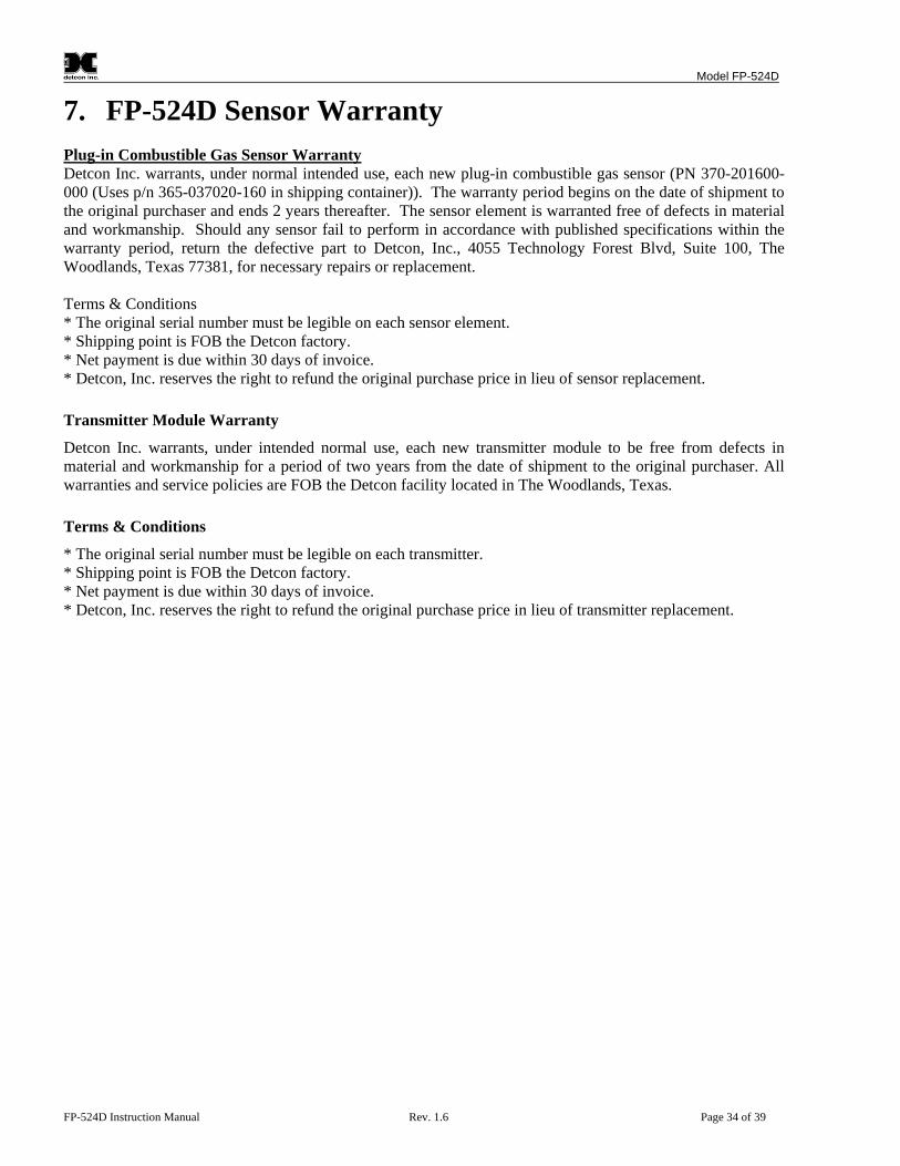
Model FP-524D
FP-524D Instruction Manual Rev. 1.6 Page 34 of 39
7. FP-524D Sensor Warranty Plug-in Combustible Gas Sensor Warranty Detcon Inc. warrants, under normal intended use, each new plug-in combustible gas sensor (PN 370-201600-000 (Uses p/n 365-037020-160 in shipping container)). The warranty period begins on the date of shipment to the original purchaser and ends 2 years thereafter. The sensor element is warranted free of defects in material and workmanship. Should any sensor fail to perform in accordance with published specifications within the warranty period, return the defective part to Detcon, Inc., 4055 Technology Forest Blvd, Suite 100, The Woodlands, Texas 77381, for necessary repairs or replacement. Terms & Conditions * The original serial number must be legible on each sensor element. * Shipping point is FOB the Detcon factory. * Net payment is due within 30 days of invoice. * Detcon, Inc. reserves the right to refund the original purchase price in lieu of sensor replacement. Transmitter Module Warranty
Detcon Inc. warrants, under intended normal use, each new transmitter module to be free from defects in material and workmanship for a period of two years from the date of shipment to the original purchaser. All warranties and service policies are FOB the Detcon facility located in The Woodlands, Texas. Terms & Conditions
* The original serial number must be legible on each transmitter. * Shipping point is FOB the Detcon factory. * Net payment is due within 30 days of invoice. * Detcon, Inc. reserves the right to refund the original purchase price in lieu of transmitter replacement.

Model FP-524D
FP-524D Instruction Manual Rev. 1.6 Page 35 of 39
8. Appendix
8.1 Specifications Sensor Type: Continuous diffusion/adsorption type
Matched-Pair Catalytic Bead type True plug-in replaceable type
Sensor Life: 3-5 years typical Measuring Ranges: 0-100% LEL Accuracy/ Repeatability: ± 3% LEL in 0-50% LEL range, ± 5% LEL in 51-100% LEL range Response Time: T50 < 10 seconds, T90 < 30 seconds Performance Testing: Complies with CSA C22.2 No. 152-M1984, ANSI/ISA S12.13 Electrical Classification: CSAc Class I, Division 1, Groups B, C, D (Tamb= -40°C to +40°C)
Class I, Zone 1, Group IIB+H2 CSAus
Class I, Division 1, Groups B, C, D (Tamb= -25°C to +40°C) Class I, Zone 1, Group IIB+H2
Approvals: CCSAUS (To maintain the CSA certification, it must be calibrated on methane) Applicable Standards CSA C22.2 No. 30-M1986 CSA C22.2 No. 142-M1987
CSA C22.2 No. 152-M1984 UL Std. No. 916 UL Std. No.1203 ANSI/ISA S12.13 Warranty: Electronics – 2 years Sensor – 2 years Environmental Specifications
Operating Temperature: -40°C to +75°C Storage Temperature: -40°C to +75°C Operating Humidity: 0-100% RH (Non-condensing) Operating Pressure: Ambient ± 10% Electrical Specifications
Input Voltage: 12-28 VDC Power Consumption: Normal operation = 68mA (<1.7 watt); Maximum = 87mA (2 watts)

Model FP-524D
FP-524D Instruction Manual Rev. 1.6 Page 36 of 39
RFI/EMI Protection: RFI Complies with ISA 92.0.01 Analog Output: Linear 4-20mA DC current 1000 ohms maximum loop load @ 24VDC 0mA All Fault Diagnostics 2mA In-Calibration 4-20mA 0-100% full-scale 22mA Over-range condition Status Indicators: 4-digit LED Display with gas concentration, full-script menu
Prompts for AutoSpan, AutoZero, Set-up Options, and Fault Reporting Faults Monitored: Loop Fault, Input Voltage Fault, Zero Fault, Sensor Fault, Processor Fault, Memory Fault, Calibration Fault(s) Cable Requirements: Power/Analog: 3-wire shielded cable
Maximum distance is 13,300 feet with 14 AWG Mechanical Specifications
Length: 8 inches (200mm), including Splashguard Width: 5.5 inches (140mm) Weight: 2.7lbs (3.4Kg) Mechanical Connection: ¾” Male NPT threaded connection Electrical Connection: three 14 gauge (maximum) wire terminal landings
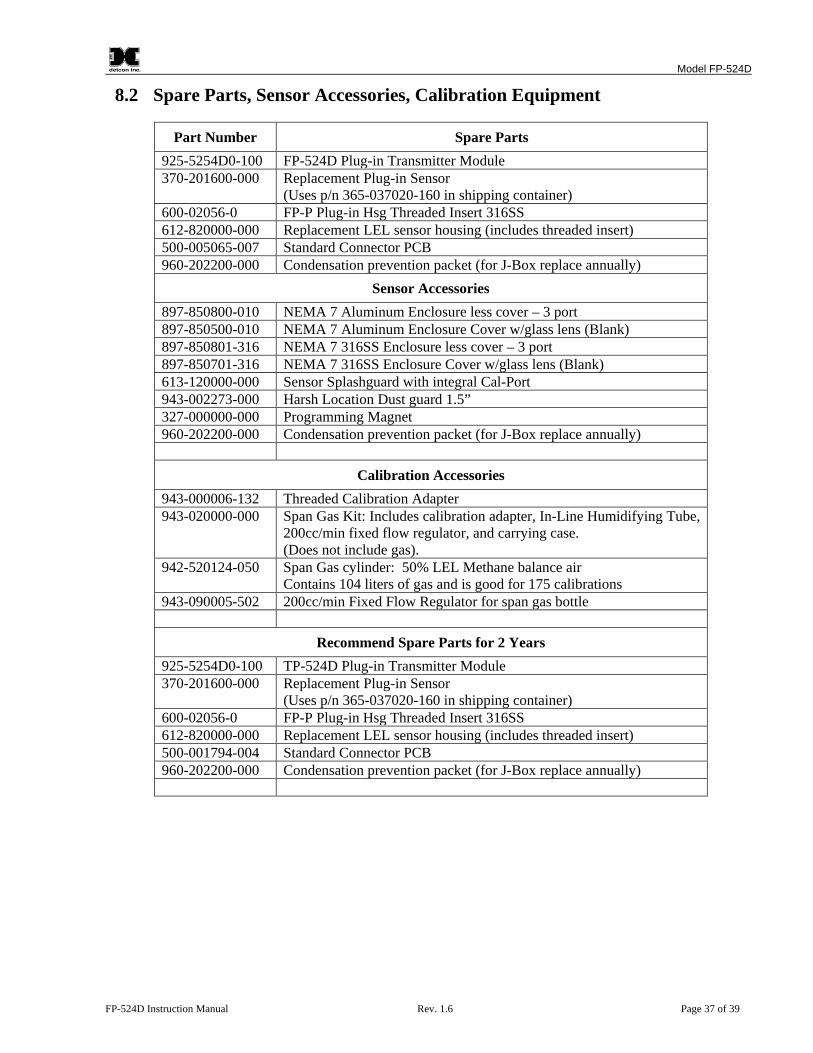
Model FP-524D
FP-524D Instruction Manual Rev. 1.6 Page 37 of 39
8.2 Spare Parts, Sensor Accessories, Calibration Equipment
Part Number Spare Parts 925-5254D0-100 FP-524D Plug-in Transmitter Module 370-201600-000 Replacement Plug-in Sensor
(Uses p/n 365-037020-160 in shipping container) 600-02056-0 FP-P Plug-in Hsg Threaded Insert 316SS 612-820000-000 Replacement LEL sensor housing (includes threaded insert) 500-005065-007 Standard Connector PCB 960-202200-000 Condensation prevention packet (for J-Box replace annually)
Sensor Accessories 897-850800-010 NEMA 7 Aluminum Enclosure less cover – 3 port 897-850500-010 NEMA 7 Aluminum Enclosure Cover w/glass lens (Blank) 897-850801-316 NEMA 7 316SS Enclosure less cover – 3 port 897-850701-316 NEMA 7 316SS Enclosure Cover w/glass lens (Blank) 613-120000-000 Sensor Splashguard with integral Cal-Port 943-002273-000 Harsh Location Dust guard 1.5” 327-000000-000 Programming Magnet 960-202200-000 Condensation prevention packet (for J-Box replace annually)
Calibration Accessories 943-000006-132 Threaded Calibration Adapter 943-020000-000 Span Gas Kit: Includes calibration adapter, In-Line Humidifying Tube,
200cc/min fixed flow regulator, and carrying case. (Does not include gas).
942-520124-050 Span Gas cylinder: 50% LEL Methane balance air Contains 104 liters of gas and is good for 175 calibrations
943-090005-502 200cc/min Fixed Flow Regulator for span gas bottle
Recommend Spare Parts for 2 Years 925-5254D0-100 TP-524D Plug-in Transmitter Module 370-201600-000 Replacement Plug-in Sensor
(Uses p/n 365-037020-160 in shipping container) 600-02056-0 FP-P Plug-in Hsg Threaded Insert 316SS 612-820000-000 Replacement LEL sensor housing (includes threaded insert) 500-001794-004 Standard Connector PCB 960-202200-000 Condensation prevention packet (for J-Box replace annually)
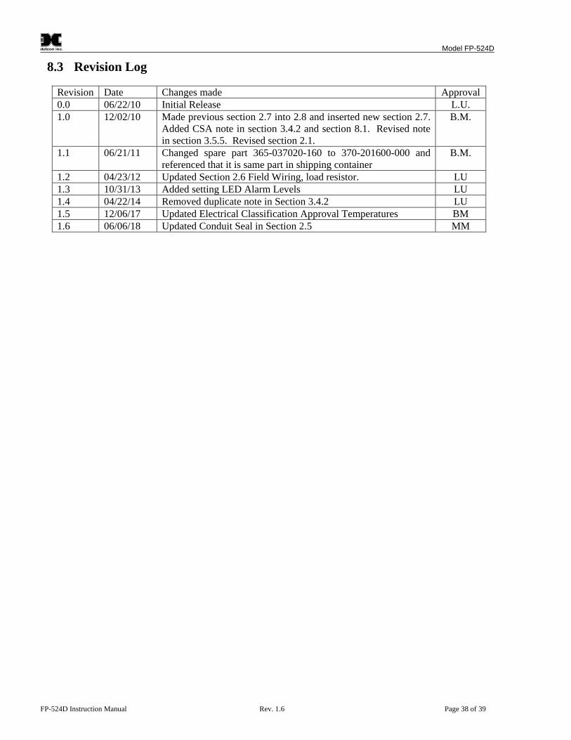
Model FP-524D
FP-524D Instruction Manual Rev. 1.6 Page 38 of 39
8.3 Revision Log
Revision Date Changes made Approval 0.0 06/22/10 Initial Release L.U. 1.0 12/02/10 Made previous section 2.7 into 2.8 and inserted new section 2.7.
Added CSA note in section 3.4.2 and section 8.1. Revised note in section 3.5.5. Revised section 2.1.
B.M.
1.1 06/21/11 Changed spare part 365-037020-160 to 370-201600-000 and referenced that it is same part in shipping container
B.M.
1.2 04/23/12 Updated Section 2.6 Field Wiring, load resistor. LU 1.3 10/31/13 Added setting LED Alarm Levels LU 1.4 04/22/14 Removed duplicate note in Section 3.4.2 LU 1.5 12/06/17 Updated Electrical Classification Approval Temperatures BM 1.6 06/06/18 Updated Conduit Seal in Section 2.5 MM

Model FP-524D
FP-524D Instruction Manual Rev. 1.6 Page 39 of 39
Shipping Address: 4055 Technology Forest Blvd, Suite 100, The Woodlands Texas 77381 Mailing Address: P.O. Box 8067, The Woodlands Texas 77387-8067
Phone: 888.367.4286, 281.367.4100 • Fax: 281.292.2860 • www.detcon.com • [email protected]
Page left intentionally blank