foz - americanradiohistory.com · information offered as pertaining to the application of any one...
TRANSCRIPT
SPECIAL SECTION fOZ
PERPETUAL
TROUBLE SHOOTER'S MANUAL VOLUME lit
Contents Pages Pages
Automatic Sensitivity Control 6 Majestic 500 Chassis 8
Wurlitzer C -4,M-4 9
Automatic Tone Control Stewart -Warner 110 22,23 Rectifier -Power Pentode
International Kadette Jr. F 19 Delayed AVC 6,21
Tuning and Noise Control Diode Detectors 7,8 Howard "Y" 11
Silvertone 16 Duo -Diode Pentodes Stewart Warner 22,23
AVC, Det. and A -f Amp. 5,6
6A7 Oscillator -Mixer Duo -Diode Triodes Electron Coupling 19,20
AVC, Det. and A -f Amp 5,6 Wave changing circuits 20,21
Phase Changer Tube 17 6B7 Flasher and AVC 16
QAVC (Squelch Circuit) 6B7 I -f and AVC 18
Howard 11 Philco 21 2525 Rectifier
General 12
Reflexed Pentodes Half Wave Rectifier 13
Emerson "Mickey Mouse" 8 Split Output 14
Emerson 678 9,10 Voltage Doubler 14
International Kadette Jr. F 11
Entire contents copyright 1934 by John F. Rider 1440 Broadway, N. Y., N. Y.
Printed in U.S.A.
www.americanradiohistory.com
AUTHORS NOTE
The information in this section of Volume IV of Rider's "Perpetual
Trouble Shooter's lanual" is offered with the hope that it will be of aid when you are called upon to analyze some of the special circuits contained in the major vol-
ume.
No effort is being made to present these facts in the form of text
covering operating principles. It is likely that you,as the reader, may find some-
thing which intrigues you, missing from these pages. If so, we ask your indulgence.
To describe every innovation present in the radio receivers produced during 1933,
would in itself, require another manual as voluminous as Volume IV. The items we
have selected for discussion have been the subjects of conversation and correspond-
ence for some time past.
With respect to material missing from this section, may we suggest
that you glance through the major volume. You will find numerous explanations of
the special circuits employed by the respective manufacturers. It was deemed un-
necessary to repeat in this section, any material which appears within the binder
of Volume IV.
Since we pay so much attention to vaeuui tubes, it might be well
to offer certain pertinent suggestions of value during the perusal of this section.
Information offered as pertaining to the application of any one type of tube, should
be interpreted as being equally applicable to any equivalent tube of like type,
although the two tubes may differ in heater rating. As an example, data concerning
the circuit design of the 6137 is applicable to the 237, although the latter bears
a different heater rating.
At the same time, we wish to call special attention to the fact
that these few pages cannot cover all possible applications of tubes and their cir-
cuits. In other words, statements made in connection with the application of any
one typo of tubo, does not limit the use of that tube to just the arrangement dis-
cussed. Numerous other modes of use may be in force, yet not included in this
brief resume.
All statements and opinions contained in this special section, are
those of the writer and in no way involve any of the manufacturers or their engineers
whose nam:s may be referred to in connection with receiver models.
We wish to expressly state that reference to any manufacturer in this section in connection with any circuit does not mean, unless a statement is
made to the contrary, that the circuit being discussed is used by that manufactur- er only. It is very likely that a large number of manufacturers make use of the system in question.. This fact must be remembered.
May we express our thanks to those who were helpful in the preparat- ion of this section
March,1934 John F. Rider
www.americanradiohistory.com
Last Minute Insertion A. -K. PAGE 4-23
MODEL 169,, 525`2
Schematic Voltage
www.americanradiohistory.com
PAGE, 1-24 A. -K.
MODEL 425,605
Schematic Voltage
2
V C 3 _^gU` >
TT
V 0 0\ ! M011 áA
,.- via--;` t0 \ e 1 ;
ATWATER KENT MFG. CO.
= 1® N33tl0 1O3N 301a
r ; ' >
MOT3A 103tl 'emu sr
8a BtaW L-
31119 D038
N33tlS 1. awf z
9a a.1N ,.
3fl1a 1 O3tl l3
1.43380
1Otl1NO7 311f11OA 9'
3018 lW90' lY390'
3M11a
H U OOEE
038 V N3387
445 vto.0oo =
11321
m u w38 I J 3 J J (AM
03tl 1_ NMI)
r ®® s
3(118
C o N
amé 038
03tl
30111
tlOv1a U 9Y
MO113A
N°V18-1338-M0113Á
U 000'OS V
> 2.; r)Jr Û f
k-'ee
ri g;
cv)
www.americanradiohistory.com
5
Duo -Diode Triodes and Pentodes 25-S,55,75,85,2A6,6C7,6B7 and 2B7 and equivalents
used as combination detector, AVC and a -f amplifiers.
These tubes are used in any number of receivers and in several ways. In some instances only detector and a -f amplification is accomplished. In other cases all three functions are secured. 1Vith respect to the latter arrangement, there are several ways in which the diode elements may be employed. Yithout any attempt to associate the circuit shown with the receivers in which it is used, we shall show various applications of these tubes, as found in receivers included in Volume IV.
The 6B7 used as an AVC, detector and a -f amplifier is shown to the left. The signal voltage (i -f) is fed into the diode plates. These two plates are joined. The
6 B7 current between the diode plates and the cathode flows through A.V.C- Orr A.F. the 500,000 ohm volume control. The direction of this current
is such that point (1) is negative with respect to point (2) which is the chassis and also the junction for the 637 cathode. The r -f, mixer or i -f tubes, whichever is being subjected to the controlling bias is joined to point (1) along the 500,000 ohm resistor. The d -c voltage developed across this resistor is fed to the tubes being controlled as the automatic volume control bias.
= MICA
500M VOL.CONT.
02 200v
500 M
At the same time, the rectified current flowing through the volume control unit is the a -f signal and is picked up by the moveable arm of the potentiometer and is fed into the control grid of the pentode portion of this tube; is amplified and passed to the load unit contained in the plate circuit.
The stronger the i -f signal fed into the 6B7, the greater the current
flow through the diode -cathode circuit and the greater the controlling bias fed to
the tubes preceding the AVC-detector-a-f amplifier, thus reducing the amplification available with this tube and maintaining the output of the a -f portion of this tube at a constant level. Of course manipulation of the manual control shown, varies the output volume. The bypass condenser shown function to keep the respective currents out of undesired oirouits.
The system shown can be considered as being basic wit', respect to the general use of duo -diode triodes and duo -diode pentodes. The circuit would function in like manner if the tube were a duo -diode -triode in place of the duo -diode pentode. In other words, the circuit function remains unchanged if the screen and suppressor grids are removed. The same is true if, instead of having just one resistor, the 500,000 ohm potentiometer constituting the load on the diode -cathode circuit, several series resis- tors were used; the fixed resistors apportioning the controlling bias for the other tubes, and the variable resistor (potentiometer) controlling the a -f input into the triode or pentode portion of the tube. A number of different arrangements of such AVC- detector and a -f amplifier circuits is shown below. The second schematic from the left
75 DET-69E-A.F
SHIELDED. LEAD #
7
0005 MICA
Ce SOM R5 0005
MICA
I C 9
005 600V C 0
1500 h VOL. DONT
CASE GROUNDED .. 500M R6
N
'E9
illustrates full wave rectification attained by employing a split or tapped input windi
in contrast to the normal half wave form of rectification shown in the other schematics.
In some instances filter networks are included so as to keep currents in correct paths.
www.americanradiohistory.com
1j
Delayed AVC Systems
This system is used in many receivers, although not necessarily exactly as shorn in the iliajestic receiver illustrated. It is usually employed when a element or tube is used_for detection and another for AVC.. At the same time, it might be well to state that all of the receivers which employ such ç -say ?2,4 7.5 csas 6555 G2H5 use of the duo -diode tubes may ,,Nr
not be employing the system for ''ÿ, P `_' ̀ delayed AVC action. The Majestic G,."0. receiver shown to the right uses
two windings to feed the two di- ode plates.
In operation, one
diode plate is used for AVC act. -
ion and the other diode plate is used for detection. Referring to
the wiring diagram, the upper plate is used for detection. The rectified current flows between the upper diode plate and the cathode via the potentiometer R-8. The audio voltage devloped across this resistor is fed into the control grid of the triode port- ion of the tube.
The lower diode plate is used for AVC. The rectified current causes a d -c voltage to be developed across the resistors R -7,R -10,R-11 and R-12. Properly apportioned this voltage is fed to the control grids of the r -f, mixer and i -f tubes. Constants are selected so that the AVC action will take place only after the signal voltage reaches certain pre -determined values.
Automatic Selectivity Control
Use of the selectivity control is shown
arm in series with grid of the triode
individual diode plates in the duo -diode triode for automatic to the left, as used in some Atwater -Kent receivers. It is
possible that this same or closely similar system is used in other receivers. Dxaminat-
Rt2 ion of this schematic and reference to any -º- other in question, will disclose whether or
not the other circuits employ a similar arrangement.
Note that the two diodesreceive their signal voltages via two fixed conden- sers, C-15 and C-16. The upper diode D-1 is
used for the AVC action. At the same tii+e,the 1st detector or mixer suppressor is joined to the sane circuit. This functions as an auto- matic selectivity control.
:.9i " a31®g°! The lower diode, D-2 is used for
detection. The rectified current flows thru the volume control potentiometer. The moving
the 0.01 mfd condenser C-18 feeds the a -f voltage into the control portion of the duo -diode triode tube.
Referring again to the AVC portion of this receiver, you will note that the control grids of the r -f and i -f tubes are joined to the controlling resistance
network.
Several of the Grunow (General Household Utilities) receivers shown ir. Volume IV make use of AVC and detector operation as stated above.
Diodo Detectors
Quite a large number of the receivers shown in Volume IV employ the equivalent of Lieu element diode detectors, made by joining the control grid to the
i
www.americanradiohistory.com
plate or the plate to the cathode. Generally such systems employ a separate tube for AVC action and another tube as the 1st a -f amplifier. Several examples of simple diode detectors are shown below. One of these, the system used in the Zenith 770 -B,775 -P is
58 '58 '5e _s_ typical of many. The 2nd /.'02T 1F 2r' D (T 1tAU(VQ
200v. j 200v.. 2+o v. a detector has its control grid
ti 82v. 82. °v 120V.
^f and anode (plate) joined to e ? 1 ÿ each other. The 500,000 ohm > °° .. volume control in series with
á -2.2 v 2
¡ a.6, -`t a 0.05 mfd condenser and a 99, 000 ohm resistor is the ooup
1.82v.í ',. 4lai ? as ling circuit to feed the a -t . ;=zl kg system.
L-1-2;21.,,, The AVC tube is ah
gV.', s.- / 4 ise=oi ose.v directly beneath the 2nd de- _°° ' .w ' _' a sv teeter tube. Its plate and gri M
1 are joined. The actuating sig-
nal is fed to the AVC tube from the high end of the grid winding feeding the 2nd de- tector tube, vie. a .0001 mfd fixed condenser. The controlling bias is fed to the grid circuits of the r -f, mixer and i -f tubes.
Score of the Fada receivers employ a diode detector for detection and AVC pureoses.The system employed in the model NE (151,152) utilizes the cathode and
plate joined. The load on the combination diode detector and AVC is the series com- bination of resistors connected between the low end of the input coil and the cathode. In reality this resistor arrange-
ment i_ two resistors of 250,000 ohms each
tapped at soave suitable point which is at the junction between the two units.
The control bias is taken off at this point and fed to the grid circuits of the i -f and mixer tubos. The
250,000 ohm resistor;the 0.05 mfd conden- ser and the 1.0 megohm volume control constitute the coupling circuit between the combination 2nd detector-.VC and the
1st a -f tube. The .00025 mfd condenser between blocking condenser is the r -f bypass unit. The sane is
between the diode cai;hode and the low end of its input
the diode cathode true winding.
and the 0.05 of the .00025 mfd
mfd condenser
Another interesting; application of combination diode detector and AVC
is that used in the Autolite 072-A receiver. The schematic is in Volume IV. The circuit to the left is the breakdown of the system. /2 waif" AS.rEMBLy
plugs shown in
2 NOOLr ToA-F
006,.. F boa
The AVC signal is fed to the i -f grid circuit via the 2.0 megohm unit R-6. The AVC signal for the r -f tube is fed to the control grid circuit via the 1.0 megohm unit R-3. The volume control unit is R-16 rated at 500,000 ohms. The moving arm picks off the d sired a -f sig- nal and feeds it to the a -f tube control grid through the .006 mfd condenser. The 2.0 megohm unit R-8 enables the applicat- ion of the control grid bias to the 1st a -f tube.
Vt'hen tracing the complete ciroui as shown in the manual, remember that the
the circuit are joined,one within the other.
www.americanradiohistory.com
h
ti 1
3 I
for detection and AVC. Reference to ing arrangement. Trace the path of the signal voltage into the first i -f tube. The amplified voltage is 6A7S
passed to the 2nd i -f trans- forner and then into the control grid of the pentode portion of the 6B7S. The amplified signal is fed into -che primary of the 3rd i -f transformer.
The signal appears in the secondary of this transformer and is fed directly into the upper diode
x
Diode in Zenith 475,760,765,767 (Chassis 2054)
In this receiver, the a -f voltage developed across the diode load re a-
Rr
1 +
6;:..15 1I
tor is fed to the volume control via a
fed to the r -f and i -f tubes, via resistance diode rectifier is the 120,000 ohm resistor.
15r DET
'56'
a aR 4
I J
ó ó
pÓp O O
1.F- '56'
a roar
Z"a DE7 'S6'
I :.ó°c
e3 rw -Ysr
7
$a
Fç
fixed condenser of 0.02 mfd. The AVC volte,e is and capacity filters. The load on the
The ..ajestic 55,59,75,195,500,560,566 (Chassis 500)
An excellent example of roflexing is found in this receiver. The first i -f tube is used for i -f and a -f amplification. The second i -f amplifier is also used
the schematic wiring diagram shows this interest -
R3
240V.
400V.
100V. 6F75 60V. 6675 250v_ OY.
*90 V. _L §8 I Tg . 1
P car-£-1J C17
R4 R6 6 1"9-
..J
2ß v.
R7 CIO
250V
r
C
12 MIS
%
Y. I
1 c."3 .1 -
R6 iT 1 C31 __ f I I J I
R.
C14
RI
CB
--II
Óq C
R14
ri7 r1 RIS
C6
plate and also into the lower diode plate via condenser G-14. The upper diodo is used for detection and the lower diode for AVC action. Referring to the detector circuit, the a -f voltage appears across the resistors R-14 and R-15. It is taken off this network at the junction between k-14 and R-15 via the condenser C-6 and the moving am on the resistor R-16.
ToA-f Tube
It then is fed back to the control grid of the triode portion of the 6F7S tube and the amplified signal is fed to the control grid of the output tube via the coupling condenser C-10. The AVC signal is developed across resistors R-8, R-9 and R-13. Thon it is applied to the mixer and i -f tubes (the 1st i -f tube) through the resistance - capacity filters shown.
Emerson "Mickey Mouse" 409,410,411,412 (A-4)
The 6F7 used in this receiver plays a
dual role. It servos as a triodo detector and a pen-
tode a -f amplifier. The rectified signal appears in
the triode plate circuit. The a -f signal is fed back
to the control grid of the pentode portion of the
tube through the .002 mfd condenser. It reappears, amplified in the plate circuit of the pentode port- ion and is fed to the output tube through the ,004
mfd condenser.
6F7 . oo4.4f 38
J
www.americanradiohistory.com
9
Reelexing in the V+urlitzer C -4,M-4
This receiver is shown on page 4-1 in Volume IV. The 6B7 tube is used t>> accomplish four functions, namely i -f amplification,detection, AVC and also a -f amp- lification.
Referring to the diagram, the 6A7 feeds the i -f signal to the control grid of the pentode portion of the tube. The amplified i -f signal appears across the orimary of the tuned i -f transformer in the platt circuit. This signal is then fed to ;he secondary of this transformer and into one of the two diode plates.
Rectification takes place and the a -f signal appears across the 1.0 meg- ohm potentiometer. The a -f signal is taken off the potentiometer (Vol. Control) by means of the moving arm. The 300,000 ohm resistor and the .0002 mfd condenser keep r -f out of the circuit, that is, enable only the a -f signal to pass back to the control grid of the pentode portion of the 6B7. The tuned i -f winding in the grid circuit does not hinder the a -f signal.
The amplified a -f signal again appears in the plate circuit of the 6B7 and is passed to the a -f output tube through the .01 mfd condenser and 50,000 ohm resistor.
The nVC ac -ion is secured by means of the signal which is fed from the pentode plate circuit to the other diode plate through the .00002 mfd condenser. This signal is at the intermediate frequency and represents but a small portion of the total i -f voltage present in the plate circuit. Rectification of the i -f signal causes a d -c
voltage across the 1.0 megphm fixed resistor. This control voltage is fed to the control grid of the 6A7 through the 1.0 megohm filter resistor.
The various resistor and condensers which have not been mentioned but are found in the associated circuits, serve to maintain the correct current paths.
Reflexing in the 6B7.(I-f,A-f, Dot, AVC)
Another version of reflexing in the 6E7 whereby four functions are aecom- lished is shown below. This particular circuit is used in the Emerson 678, Type 1. This
circuit provides amplification at an intermediate freq- 637 1/725Kc uency, detection, delayed AVC and a -f amplification. :aoosa/
control which is present rol knob. Now, it should portion of this resistor
Referring to the schematic diagram, the i -f transformer feeds into the control grid of the pentode portion of the tube. The amplified i -f signal appears ac- ross the i -f transformer primary in the plate circuit. This winding is coupled to the secondary of the same i -f transformer and the i -f signal is fed back to the upper diode plate. It also is fed to the lower diode plate via the .0005 mfd condenser shown connected to the diodes. wore about the second diode later.
The upper diode is employed for detection. An examination of the circuit shows that the 200,000 ohm volume control potentiometer is a part of the rectifying or detector circuit. The portion of the complete volume
in the detector circuit, depends upon the setting of the oont- be understood that the a -f voltage is developed across whatever remains in the detector circuit. If the moveable arm were
shifted to the extreme left end of the 200,000 ohm potentiometer, the entire unit would be in the circuit and the maximum voltage would be developed. If the am were moved to the extreme right end of the control, the minimum voltage would be developed.
Assuming that some value of a -f voltage is developed across the volume control potentiometer, it thon is passed back to the control grid of the 6B7 pentode via the .01 mfd condenser and the tuned i -f transformer secondary. The 200,000 ohm resistor and the .0005 mfd condenser related to the secondary of the output i -f trans-
www.americanradiohistory.com
lU
former keep i -f currents out of the reflexed audio system. Thus the action of this a -f
volume control is somewhat different than the conventional. After the a -f signal has
been passed into the control grid circuit, it again reappears amplified in the plate
circuit and passing through the primary of the output i -f transformer, it passes through
the primary winding of the a -f transformer.
eeferring to the AVC circuit, the i -f signal passed to the lower diode
plato is rectified in the diode plate -cathode circuit containing 1.0 megohm resistor
and the 1000 ohm noise suppressor resistor, which also supplies the minimum bias for
the 6B7 tube. The rectified signal, properly bypassed with condensers develops a d -c
voltage across the diede -cathode rectifier and the controlling voltage is fed to the
r -f and mixer control grid systems.
'hile it is true that the system shown in connection with this discussion
is native to the Emerson 678, very similar systems are to be found in many other
receivers shown in Volume IV.
Another version of reflexing in the 657 is shown below. This is very
similar to the previous circuit, except for the fact that rectification for the prod-
uction of the a -f and :_VC voltage is accomplished at the same time and with the sale
diode plates. A brief explanation of this circuit
might not be amiss.
The i -f signal is introduoed into
the control grid circuit of the 687. The amplif-
ied reproduction appears in the plate circuit;
in the primary of the output i -f transformer, be-
ing coupled to the secondary, the i -f signal is
fed back to the two diode plates, which are
joined to each other.
is evident in the sohematio,the
detector circuit contains the 200,000 ohm fixed
filter resistor and the .0005 mfd condenser,which
tend to keep i -f currents out of the a -f circuit.
This circuit also includes the 200,000 ohm poten-
tiometer a -f volume control; that is, that port-
ion of the control left in the cirouit between the
the 1000 ohm potentiometer in the 6B7 cathode circuit. moveable arm and its connection to
For any a -f volume control adjustment other than maximum volume, the
a -f volume control acts as a divider. Hoe ever, a -f voltage being developed across the
aotive portion of the unit, the audio signal is fed back to the control grid circuit
of the 6B7 through the .01 mfd coupling condenser and the tuning i -f winding. The a -f
signal, properly amplified reappears in the plate circuit and without being impeded by
the i -f transformer primary is passed to a -f winding which feeds the output tubes.
Concerning the AVC voltage, this is developed at the time that the a -f
voltage is produced in the detector circuit. By tapping into the detector circuit at
the intersection of the output i -f transformer secondary and the 200,000 ohm resistor,
the proper AVC voltage is secured for the mixer and r -f tube control grids.
This system like the other, different perhaps in constants,will be found
in numerous receivers listed in Volume IV.
When aligning receivers which employ a separate diode plate for the AVC
signal, it is usually possible to ground this plate so as to reWer the AVC system in-
active. However, it is best, whenever possible to avoid grounding any live circuits and
to supply as weak a test signal as is available, so that alignment will be possible
without setting off the AVC system.
Obviously, those receivers which employ a common junction between the two
diode plates and both are used for detection and AVC must be aligned with a weak signal.
www.americanradiohistory.com
11
Reflexing in the International Kadet,e Jr. (R -f, Dot, A -f)
This receiver anploys only two tubes. One of these, a 6F7 accomplishes
three functions, namely, r -f amplifier, detector and a -f amplifier. The other tube, a
12A7 is described elsewhere in this supplement.
The production run of this receiver
of these types are shown in Volume
IV, but only one will be shown in this discussion. It is needless to
illustrate all of the types because
they differ primarily in the locat-
ion of the volume control. As far as the reflexing system is concerned ono illustration will suffice. T Z5
As is evident the Oe tube contains ono cathode, four
grids and two plates. The cathode is common to all the elements within the tube. Actually this tube is two tubes in one; a pentode and a triode.s Reading from bottom to top, the elem-
ents are as follows: triode plate, triode control grid, common cathode, pentode control grid, pentode screen grid, pentode suppressor and pentode plate.
entailed four
The r -f signal is fed into the pentode control grid. _Amplified it re- appears in the pentode plate circuit (the upper plate), It is significant to note that this plate circuit contains a winding which links the pentode plate with the input of the output tube. At the same time, the plate circuit is also coupled to another tuned circuit through a condenser A-502 .A. Since the winding which joins the pentode plate to the output tubo offers a high impedance to r -f currents, the signal will pass to the tuned circuit.
As is evident this tunod circuit contains a grid leak and condenser and is a part of the control grid system of the triode portion of the tube. This is the
detector input circuit. The rectified signal then appears in the plato circuit of the triode and is fed to the control grid of the pentode via the coupling condenser A-339
of .005 mfd. The volume control is in effect a variable resistor aoross the control grid to chassis circuit.
The amplified a -f signal again appears in the plate circuit of the pen- tode, but in this case, its path is through the winding to the blocking condenser A-338 and to the output tube control grid. The actual load upon the plate circuit of the 6F7 pentode at audio frequencies is the 0.25 megohm resistor R-265. The a -f currents do not flow through the previously mentioned coupling condenser A -502-A because its
impedance at audio frequencies is very ranch greater than that of the winding. Thus the 6F7 tube acts as an rf amplifier, detector and a -f amplifier, the first and third funct- ions being performed by the pentode section. The detector action by the triode section.
Tuning and Noise Control In Howard Iilodel "Y"
The schematic wiring diagram of this receiver is. shown in Volume IV on
Howard Page 4-5. The "Y" designation must be added to the models shown in the corner card listing. The data shown in solid lines constitutes the "X" models. The additions shown in dotted lines comprise the change to the "Y" models.
Referring to the diagram, this receiver provides for tuning and noise control in the following manner. The i -f signal is fed to the diode plates of the 6B7.
The load on this portion of the duo -diode pentode tube is the 500,000 ohm resistor
www.americanradiohistory.com
12
;b2763. Current flow through the diode plate -cathode circuit establishes a d -c voltage across this resistor. AdC voltage is fed to the r -f, mixer and i -f tubes through the 200,000 ohm resistor which joins the diode tube load.
At the same time, the a -f voltage which is also developed across the same resistor is fed to the a -f tube through the 200,000 ohm resistor in series with the .05 mfd condenser and the 500,000 potentiometer type of volume control. This unit is designated as 2725. It is significant to note two other facts. One of these is the location of the neon tuning indicator in the plate circuit of the pentode portion of the 6B7. The other is the electrical connection between the control grid of the 6B7 and filter resistor joined to the duo -diode load. At the present moment we are considering only the solid lines.
From what has been said, the 6B7 performs the role of 2nd detector and AVC. If for a;oment we assume the passage of a signal through the tube, so that a controlling negative bias is apolied to the r -f, mixer and i -f tubes, a negative voltag will also be applied to the contre, grid of the 6B7, since that element joins a common junction with the aforementioned control grid returns.
The application of a negative bias upon the control grid of the 6B7 will naturally reduce its plate current. The reverse is naturally true. If there is no signal passing through the 6B7, its plate current will be maximum, since there is no negative bias being applied to the control grid. This is the situation when the receive is not tuned to a station. The result is that the neon tube glows with maximum bright- ness. The design of the receiver is such that this glow flashes the word "detuned".
When a signal is applied, the negative bias is applied; the plate cur- rent is reduced and the neon tube contains a shorter column of brilliant light and the word "tuned" is visible. It is apparent that the finer the tuning, the less the light in the neon tube. (Complete instructions pertaining to the adjustment of this tuning light accompany the service data in Volume ITT. See page Howard 4-4.)
Now for the noise control. Reference to the schematic wiring diagram will show that the control grid of the noise control tube (shown in dotted lines) also is connected to the point of negative potential which supplies the various tubes in the reoeiver. Furthermore the screen or the noise control tube joins the screen of the 6B7. On the other hand the plate of the noise control tube joins the screen of the 1st a -f tube. Let us now see what happens.
During the time that the receiver is being tuned and no signal is heard or rather,no signal is passed into the 6B7, the preceding tubes are functioning with maximum gain. Normally this would result in noise. However, since there is no negative bias on the noise control tube, its plate current is quite high. As a matter of fact it is so great that it reduces the voltage at the screen (to which it is joined) of the a -f tube and also the plate voltage of the a -f tube, to the extent that this tube does not amplify. Consequently, the receiver output is quiet.
When a station is tuned in accurately, the maximum bias (negative) is applied to the control grid of the noise s.ppressor; its plate current is reduoed to minimum and the voltage at the screen and plate of the a -f tube are maximum and great- est gain is secured.
The 25-Z-5 Rectifier
This tube, quite commonly used in the modern universal AC -DC receiver is in reality two half wave rectifiers contained in one envelope. The envelope cont- ains two anodes, two cathodes and a double filament or heater. The anodes and cathodes are independent, whereas the two heaters have a common connection and are used in ser- ies.
'When employed as a conventional half wave rectifier, the two anodes are joined in parallel and the two cathodes are joined in parallel. Becau~e of the design of the rectifier, it is possible to employ each set of anode-cathodesas an
www.americanradiohistory.com
13
individual half wave rectifier. At the same time, one set of elements comprising a half wave rectifier can be employed to feed one load and the other set can be used to feed an entirely separate load.
Since the complete rectifier with the elements connected in parallel is rated at 100 milliamperes, it is simple to understrnd that each pair of elements comprising a half wave rectifier would be rated at 50 milliamperes.
A salient feature of the 25Z5 is the ability to supply an output vol- tage, when used on an AC line, which,without recourse to a step-up power transformer, will be about twice the value of the input voltage. In other words, the tube can be used in a voltage doubler circuit.
The three items mentioned thusfar are to be found in abundance in AC -DC receivers illustrated in Volume IV. It might be well at this time to offer basic circuits illustrative of the conditions mentioned. This to be followed by some examp- les of the practical applications.
The 25-Z-5 As A Conventional half Wave xectifier
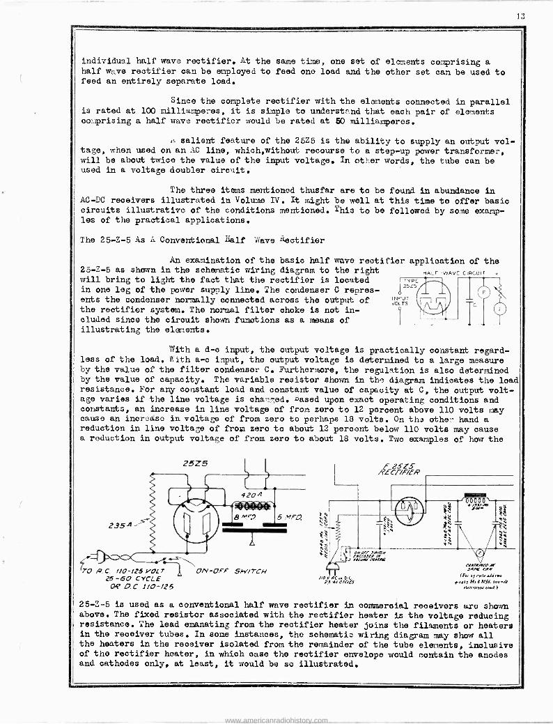
An examination of the basic half wave rectifier application of the 25-Z-5 as shown in the schematic wiring diagram to the right will bring to light the fact that the rectifier is located T PE
in one log of the power supply line. The condenser C renres- 25Z5
ents the condenser normally connected across the output of INPUT TS
the rectifier system. The normal filter choke is not in- cluded since the circuit shown functions as a means of illustrating the elements.
HALF -WAVE CIRCUIT +
With a d -o input, the output voltage is practically constant regard- less of the load. With a -c input, the output voltage is determined to a large measure by the value of the filter condenser C. Furthermore, the regulation is also determined by the value of capacity. The variable resistor shown in the diagram indicates the load resistance. For any constant load and constant value of capacity at C, the output volt- age varies if the line voltage is charged. Lased upon exact operating conditions and constants, an increase in line voltage of from zero to 12 percent above 110 volts may cause an increase in voltage of from zero to perhaps 18 volts. On the other hand a reduction in line voltage of from zero to about 12 percent below 110 volts may cause a reduction in output voltage of from zero to about 18 volts. Two examples of how the
) 70 A.C. 1/0-125 VOL ON-OFF
25 -60 CYCLE oSP O.0 110-125
25Z5
5W/7CH
0
f 2SZ5 RECT/F/ER
I OMOFF Jw?M [.YCLOJLO /M J YO/UNI COAlAOi
//OYACe.DC 25-64,C faf5
4 -/.8.11 -Ado lu"
CAN/AMA, JAN( CON
1Fo. aJ ed., add two 4,403 M. 8 Mld. Yaa ru4
elreroqria ro.d.l
25-Z-5 is used as a conventional half wave rectifier in commercial receivers are shown above. The fixed resistor associated with the rectifier heater is the voltage reducing resistance. The lead emanating from the rectifier heater joins the filaments or heaters in the receiver tubes. In some instances, the schematic wiring diagram may show all the heaters in the receiver isolated from the remainder of the tube elements, inclusive of the rectifier heater, in which nase the rectifier envelope would nontain the anodes and cathodes only, at least, it would be so illustrated.
www.americanradiohistory.com
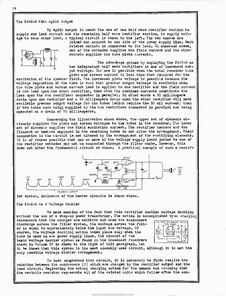
The 25-Z-5 with Split Output
By split output is meant the use of one half wave rectifier section to supply one load circuit and the remaining half wave rectifier section, to supply volt- age to some other load. A typical circuit is shown to the left. The two anodes are
joined and connect to ono side of the power supply line. Each related cathode is connected to its load. In numerous cases,
one of the cathodes supplies the field current and the other cathode supplies the tube plate currents.
The advantage gained by employing the 25-Z-5 as two independent half wave rectifiers is one of increased out- put voltage. Its use is possible when the total receiver tube plate and screen current is less than that required for the
excitation of the speaker field. The increased plate voltage is possible because the voltage regulation of the tube is such that greater output voltage is available when the tube plate and screen current load is applied to one rectifier and the field current
is the load upon the other rectifier, than when the combined currents constitute the load upon the two rectifiers connected in parallel. In other words a 30 milliampere drain upon one rectifier and a 40 milliampere drain upon the other rectifier will make available greater output voltage for the tubes (which require the 30 mil current) than if the tubes were being supplied by the two rectifiers connected in parallel and being
operated at a drain of 70 milliamperes.
Concerning the illustration shown above, the upper set of elements ob-
viously supplies the plate and screen voltages to the tubes in the receiver. The lower
set of elements supplies the field excitation current. The rectifier heaters and the
filament or heaters employed in the remaining tubes do not alter the arrangement. Their
connection in the circuit is not altered by the arrangement of the rectifying elements. It is of course possible that one or more of the voltage supply leads joined to one of
the rectifier cathodes may not be connected through the filter choke, However, this
does not alter the fundamental circuit as shown. A practical example of such a rectif-
!.F COMP 2f 71 687 !3 7B 78 25-Z-5
F/LAMENT 0/421//7
ier system, inclusive of the heater circuits is shown above.
The 25-Z-5 As A Voltage Doubler
'fie made mention of the fact that this rectifier enables voltage doubling without the use of a step-up power transformer. The action is accomplished byso charging condensers that the charges are additive and when the condensers discharge across the filter system, the voltage across the filt- er is equal to approximately twice the input a -o voltage. Of course, the voltage doubling action takes place only when the tube is used on a -c power supply lines. The circuit of the
basic voltage doubler system as found in the broadcast receivers
shown in Volume IV is shown to the right of this paragraph. Let
it be known that this system is the most commonly used circuit, although it is not the
only possible voltage doubler arrangement.
To best comprehend this circuit, it is necessary to first realize the
relation between the condensers (C) which are charged by the rectifier output and the load circuit. Neglecting the actual charging action for the moment and assuming that
the variable resistor represents all of the related units which follow after the con-
www.americanradiohistory.com
15
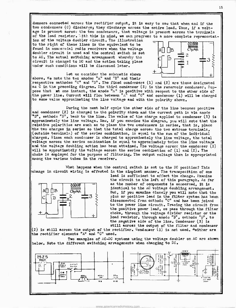
densers connected across the rectifier output, it is easy to see that when and if the two condensers (C) discharge; they discharge across the entire load. Thus, if a volt- age is present across the two condensers, that voltage is present across the terminals of the load resistor. :ith this in mind, we can progress to a more complete representat- ion of the voltage doubler circuit. The illustration to the right of these lines is the equivalent to be found in oomne-cial radio receivers when the voltage doubler circuit is used and the control switch is set to AC. The actual switching arrangement whereby the circuit is changed to DC and the action taking place under such conditions will be discussed later.
Let us consider the schematic shown above. We note the two anodes "A" and "B" and their respective cathodes "C" and "D". The fixed condensers (1) as C in the preceding diagram. The third condenser (3) is
pose that at one instant, the anode "A's is positive with the power line. Current will flow between "A" and "C" and to some value approximating the line voltage and with the
end (2) are those desie;nated the reservoir condenser. Sup - respect to the other side of condenser (1) will be charged polarity shown.
During the next half cycle the other side of the line becomes positive and condenser (2) is charged to the polarity shown and the current path is via anode ~B", cathode "D", back to the line. The value of the charge applied to condenser (2) is
approximately the line voltage. Now, if you examine the diagram, you will note that the relative polarities are such as to place the two condensers in series, that is, place the two charges in series so that the total charge across the two extreme terminals, (outside terminals) of the series combination, is enual to the sum of the individual charges. Since each condenser is charged to approximately the line voltage, the total voltage across the series combination is equal to approximately twice the line voltage and the voltage doubling action has been attained. The voltage across the condenser (3) will be approximately the voltage across the series combination of (1) and (2). The choke is employed for the purpose of filtering. The output voltage then is appropriated among the various tubes in the receiver.
What happens when the control switch is set to the DC position? This change in circuit wiring is effected in the simplest manner. The transposition of one
lead is sufficient to effect the change. Examine the circuit to the left of this paragraph. As far as the number of components is concerned, it is
identical to the AC voltage doubling arrangement. But, if you examine closely you will noto that the plus or positive lead in the filter system has been disconnected from cathode "C" and has been joined to the power line circuit. Tracing the circuit from the positive power lead, we pass through the filter choke, through the voltage divider resistor or the load resistor, through anode "B", cathode "D", to the negative side of the line. Condenser (3) is
still across the output of the filter and condenser is still across the output of the rectifier. Condenser (1) is not used. l'ieither are rectifier elements "A" and "C" used.
Two examples of AC -DC systems using the voltage doubler on AC are shown
below. Note the different switching arrangements when changing to DC.
www.americanradiohistory.com
1(i
S ILV'LFiTONE 1722,1732,1722.Y,1732X
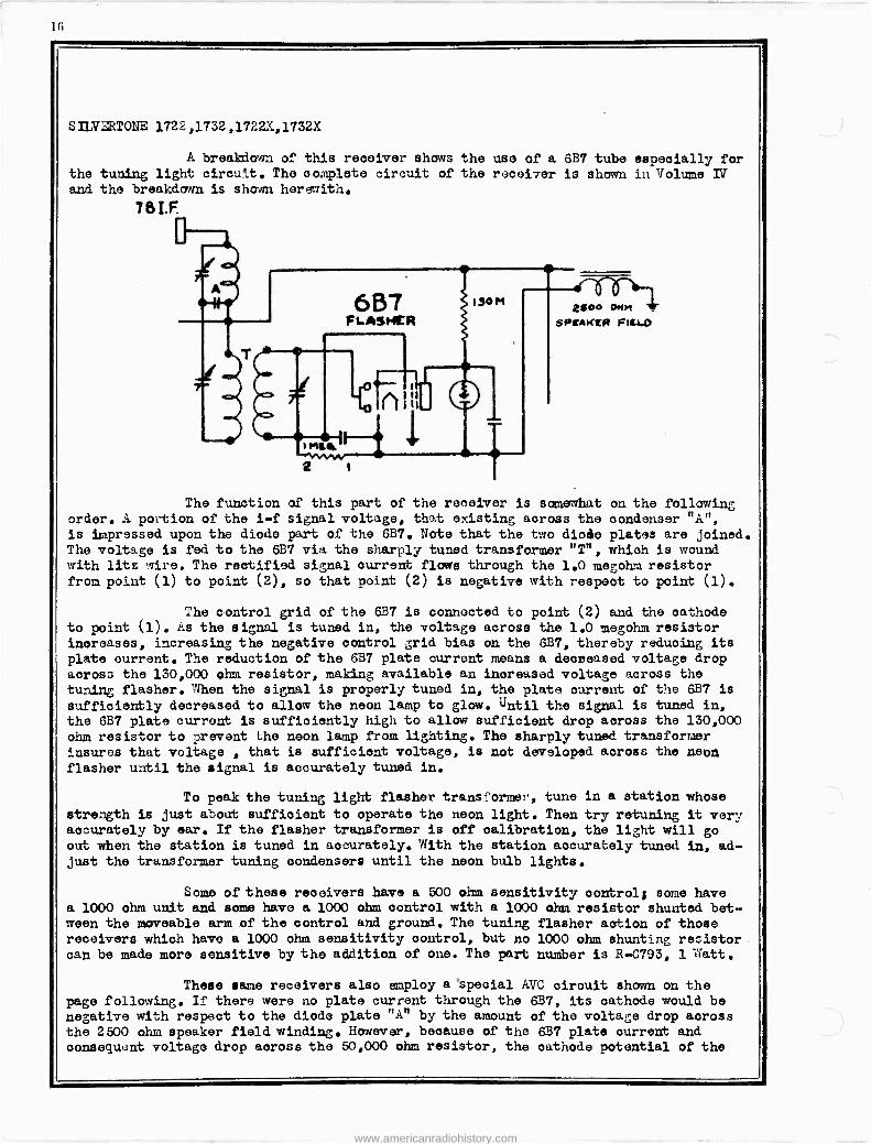
A breakdown of this receiver shows the use of a 6B7 tube especially for the tuning light circu'.t. The complete circuit of the receiver is shown in Volume IV and the breakdown is shown herewith.
7&I.F
6B7 FLASHER
lit
190M ¿goo *Wm
SPEAKER FILLO
The function of this part of the receiver is somewhat on the following order. A po -ion of the i -f signal voltage, that existing across the condenser "A", is impressed upon the diode part of the 6B7. Note that the two diode plates are joined. The voltage is fed to the 6B7 via the sharply tuned transformer "T", which is wound with lits wire. The rectified signal current flows through the 1.0 megohm resistor from point (1) to point (2), so that point (2) is negative with respect to point (1).
The control grid of the 6B7 is connected to point (2) and the cathode to point (1). As the signal is tuned in, the voltage across the 1.0 megohm resistor increases, increasing the negative control grid bias on the 6B7, thereby reducing its plate current. The reduction of the 6B7 plate current means a decreased voltage drop across the 130,000 ohm resistor, making available an inoreasod voltage across the tuning flasher.' When the signal is properly tuned in, the plate current of the 6B7 is sufficiently decreased to allow the neon lamp to glow. Until the signal is tuned in, the 6B7 plate current is sufficiently high to allow sufficient drop across the 130,000 ohm resistor to prevent the neon lamp from lighting. The sharply tuned transformer insures that voltage , that is sufficient voltage, is not developed across the neon flasher until the signal is accurately tuned in.
To peak the tuning light flasher transformer, tune in a station whose
strength is just about sufficient to operate the neon light. Then try retuning it very accurately by ear. If the flasher transformer is off calibration, the light will go out when the station is tuned in accurately. With the station accurately tuned in, ad- just the transformer tuning condensers until the neon bulb lights.
Some of these receivers have a 500 ohm sensitivity control; some have a 1000 ohm unit and some have a 1000 ohm control with a 1000 ohm resistor shunted bet- ween the moveable arm of the control and ground. The tuning flasher action of those receivers which have a 1000 ohm sensitivity control, but no 1000 ohm shunting resistor can be made moro sensitive by the addition of one. The part number is R-0793, 1 Watt.
These same receivers also employ a special AVC circuit shown on the page following. If there were no plate current through the 6B7, its cathode would be negative with respect to the diode plate "A" by the amount of the voltage drop across the 2500 ohm speaker field winding. However, because of the 6B7 plate current and consequent voltage drop across the 50,000 ohm resistor, the cathode potential of the
www.americanradiohistory.com
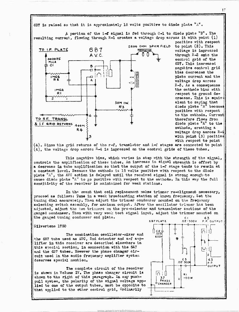
l7
6B7 is raised so that it is approximately 15 volts positive to diode plate "A".
A portion of the i -f signal is fed through C-1 to diode plate "B". The
resulting current, flouring through R-1 creates a voltage drop across it with point (1) positive with respect
6 B asco OMM SPKR FIELD to point (2). This
TO I.F. PLATE voltage is impressed
A.V.C. through R-2 onto the 000025 MICA
control grid of the
CI 6B7. This increased
1_ negative control grid ^ 1 bias decreases the I ME4 --o I 1
I I I - plate current and the R 2 voltage drop across
R-3. As a consequence IME4 the cathode bias with RI respeot to ground de-
creases. This is equiv
SoM 1W. slant to saying that
-- R3 diode plate "A" become positive with respect
¢ to the cathode. Curren To R.F, TRANSE T therefore flows from
& I.F. ,aRwo RETURNS 400m t diode plate "A" to the
R# cathode, creating a voltage drop across R
3 with point (3) positiv with respect to point
(4). Since the grid returns of the r -f, translator and i -f stages are connected to point (4), the voltage drop across R-4 is impressed on the control grids of these tubes.
This negative bias, which varies in step with the strength of the signal, controls the amplification of these tubes. An increase in signal strength is offset by a decrease in tube amplification so that the output of the i -f stage tends to remain at a constant level. Because the cathode is 15 volts positive with respect to the diode
plate "A", the AVC action is delayed until the received signal is strong enough -to cause diode plate "A" to go positive with respect to the cathode. In this way the full sensitivity of the receiver is maintained for weak stations.
In the event that coil replacement makes trimmer re -alignment necessary, proceed as follows: Tune in a weak broadcasting station of known frequency. Set the tuning dial accurately. Then adjust the trimmer condenser mounted on the frequency selecting switch assembly, for maximum output. After the oscillator trimmer has been adjusted, adjust the two trimmers on the pre -selector and transalator sections of the ganged condenser. Then with very weak test signal input, adjust the trimmer mounted on the ganged tuning condenser end plate. cl 4 3
Silvertone 1750
The combination oscillator -mixer and
the 6B7 tube used as AVC, 2nd detector and a -f amp-
lifier in this receiver are described elsewhere in this special section, in connection with the 6A7 and the 6B7 tubes. However the phase changer cir-
cuit used in the audio frequency amplifier syste.n
deserves special mention.
The complete circuit of the reooiver
is shown in Volume IV. The phase changer cirouit is
shown to the right of this paragraph. In any push-
pull system, the polarity of the signal voltage app-
lied to one of the output tubes, must be opposite to
that applied to the other control grid, Ordinarily
6B7PLATE
C2 003 600V
.02-300V P.P.P. OUTPUT
I(l
LV
RI
I 0 0 M
2L- 43 P P.
OUTPUT
www.americanradiohistory.com
I
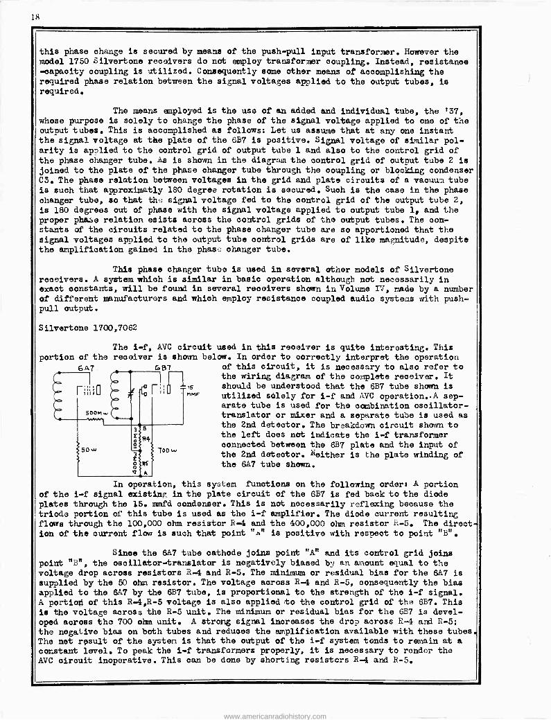
The i -f, AVC circuit used in this receiver is quite interesting. This receiver is shown below. In order to correctly interpret the operation
G g7 of this circuit, it is necessary to also refer to the wiring diagram of the complete receiver. It
should be understood that the 687 tube shown is utilized solely for i -f and AVC operation..A sep- arate tube is used for the combination oscillator - translator or mixer and a separate tube is used as the 2nd detector. The breakdown circuit shown to the left does not indicate the i -f transformer connected between the 6B7 plate and the input of
7oow the 2nd detector. Neither is the plate winding of the 6A7 tube shown.
this phase change is secured by model 1750 Silvertone receivers -capacity coupling is utilized.
required phase relation between required.
means of the push-pull input transformer. However the do not employ transformer coupling. Instead, resistance Consequently some other means of accomplishing the the signal voltages applied to the output tubes, is
The means employed is the use of an added and individual tube, the '37,
whose purpose is solely to change the phase of the signal voltage applied to one of the output tubes. This is accomplished as follows: Let us assume that at any one instant the signal voltage at the plate of the 687 is positive. Signal voltage of similar pol- arity is applied to the control grid of output tube 1 and also to the control grid of the phase changer tube. As is shown in the diagram the control grid of output tube 2 is
joined to the plate of the phase changer tube through the coupling or blocking condenser C3. The phase relation between voltages in the grid and plate circuits of a vacuuu tube is such that approximatly 180 degree rotation is secured. Such is the case in the phase changer tube, so that the signal voltage fed to the control grid of the output tube 2,
is 180 degrees out of phase with the signal voltage applied to output tube 1, and the proper phase relation esista across the control grids of the output tubes. The con- stants of the circuits related to the phase changer tube are so apportioned that the signal voltages applied to the output tube oontrol grids are of like magnitude, despite the amplification gained in the phase changer tube.
This phase changer tubo is used in several other models of Silvertone receivers. A system which is similar in basic operation although not necessarily in exact oonstants, will be found in several receivers shown in Volume IV, made by a number of different manufacturers and which employ resistance coupled audio systems with push- pull output.
Silvertone 1700,7062
portion of the
6e7
r I I I i p
500H,.,
s ?IMF
In operation, this sy::tem functions on the following order: A portion of the i -f signal existing in the plate circuit of the 6B7 is fed back to the diode plates through the 15. mmfd condenser. This is not necessarily reflexing because the triode portion of this tube is used as the i -f amplifier. The diode current resulting flows through the 100,000 ohm resistor R-4 and the 400,000 ohm resistor h-5. The direct-
ion of the current flow is such that point "h" is positive with respect to point "B".
Since the 6A7 tube cathode joins point "A" and its control grid joins point "B", the oscillator -translator is negatively biased by an amount equal to the voltage drop across resistors R-4 and R-5. The minimum or residual bias for the 6A7 is supplied by the 50 ohm resistor. The voltage across R-4 and R-5, consequently the bias applied to the 6A7 by the 6B7 tube, is proportional to the strength of the i -f signal. A portion of this R -4,R-5 voltage is also applied to the control grid of the 687. This
is the voltage across the R-5 unit. The minimum or residual bias for the 6E7 is devel- oped across the 700 ohm unit. A strong signal increases the drop across R-4 and R-5; the negative bias on both tubes and reduoes the amplification available with these tubes. The net result of the system is that the output of the i -f system tends to remain at a
constant level. To peak the i -f transformers properly, it is necessary to render the AVC circuit inoperative. This can be done by shorting resistors R-4 and R-5.
www.americanradiohistory.com
19
Rectifier -Poher Pentodes
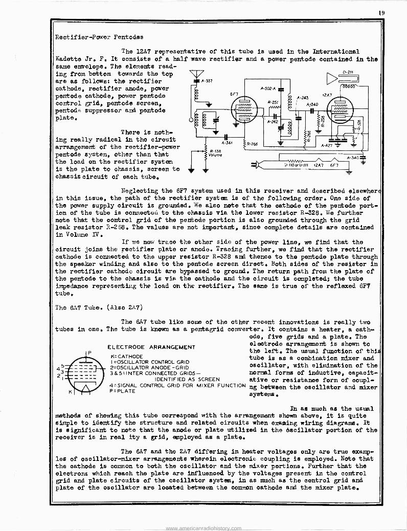
The 12A7 representative Kadette Jr. F. It consists of a half wave
same envelope. The elements read- ing from bottom towards the top are as follows: the rectifier cathode, rectifier anode, power pentode cathode, power pentode control grid, pentode screen, pentode: suppressor and pentode plate.
There is noth- ing really radical in the circuit arrangement of the rectifier -power pentode system, other than that the load on the rectifier system is the plate to chassis, screen to chassis circuit of each tube.
of this tube is used in the International rectifier and a power pentode contained in the
Neglecting the 6F7 system used in this receiver and described elsewher in this issue, the path of the rectifier system is of the following order. One side of the power supply circuit is grounded. We also note that the cathode of the pentode port- ion of the tube is oonnected to the chassis via the lower resistor R-328. We further note that the control grid of the pentode portion is also grounded through the grid leak resistor R-258. The values are not important, since complete details are contained in Volume IV.
If we now trees the other side of the power line, we find that the circuit joins the rectifier plate or anode. Tracing further, we find that the rectifier cathode is connected to the upper resistor R-328 and thence to the pentode plate through the speaker winding and also to the pentode screen direct. Both sides of the resistor in the rectifier cathode circuit are bypassed to ground. The return path from the plate of the pentode to the chassis is via the cathode and the circuit is completed; the tube impedance representing the load on the rectifier. The same is true of the reflexed 6F7 tube.
The 6A7 Tube.
tubes in one.
(Also 2A7)
The 6A7 tube like The tube is known as
some a pentagrid
ELECTRODE ARRANGEMENT
K=CATHODE I =OSCILLATOR CONTROL GRID 2=OSCILLATOR ANODE -GRID 3&5=INTER CONNECTED GRIDS
IDENTIFIED AS 4=SIGNAL CONTROL GRID FOR P=PLATE
SCREEN MIXER FUNCTION
of the other recent innovations is really two converter. It contains a heater, a cath-
ode, five grids and a plate. The electrode arrangement is shown to the left. The usual function of thi tube is as a combination mixer and oscillator, with elimination of the normal forms of inductive, oapacit- ative or resistance form of ooupl- ng between the oscillator and mixer systems.
In as much as the usual methods of showing this tube correspond with the arrangement shown above, it is quite simple to identify the structure and related circuits when exaaiing wiring diagrams. It
is significant to note that the anode or plate utilized in the Oscillator portion of the receiver is in real ity a grid, employed as a plate.
The 6A7 and the 2A7 differing in heater voltages only are true examp- les of oscillator -mixer arrangements wherein electronic coupling is employed. Note that the cathode is common to both the oscillator and the mixer portions. Further that the electrons which reach the plate are influenced by the voltages present in the control grid and plate circuits of the oscillator system, in as match as the control grid and plate of the oscillator are located between the common cathode and the mixer plate.
www.americanradiohistory.com
20 I
The basic circuit
of the 2A7 and 6A7 pentagrid con-
verter is shown to the right of this paragraph. The constants of the var-
ious components shown are of little
importance at this time. It should
be understood that the circuit as shown is typical of the mode of app- lication, yet,is not a true circuit
of any particular receiver. Examples of such will follow later.
In operation, electrons emitted from the cathode can be controlled in
their flow to the oscillator anode (grid 2) by grid 1. The oscillator grid circuit, therefore can be operated to oscillate at whatever frequency is required. The electron
stream flowing through grid 1 will naturally be modulated at this frequency. Since the
oscillator anode is really a grid, the modulated electron stream also cames under the
influence of grid 3, which is operated at a positive potential with respect to the cath- ode. Consequently the electron stream is accelerated toward the plate P.
Now, the application of a signal voltage to the control grid 4, still
further modulates the electron stream, which is already modulated at the oscillator sz-stem frequency, thus producing in the plate circuit, currents which are the various
combinations of the oscillator and signal frequencies. The plate circuit of the combin- ation mixer -oscillator contains the tuned primary of the i -f transformer, hence is re-
sonant to this one frequency only. The final result is that the intermediate frequency
only, is present across the secondary of the i -f transformer.
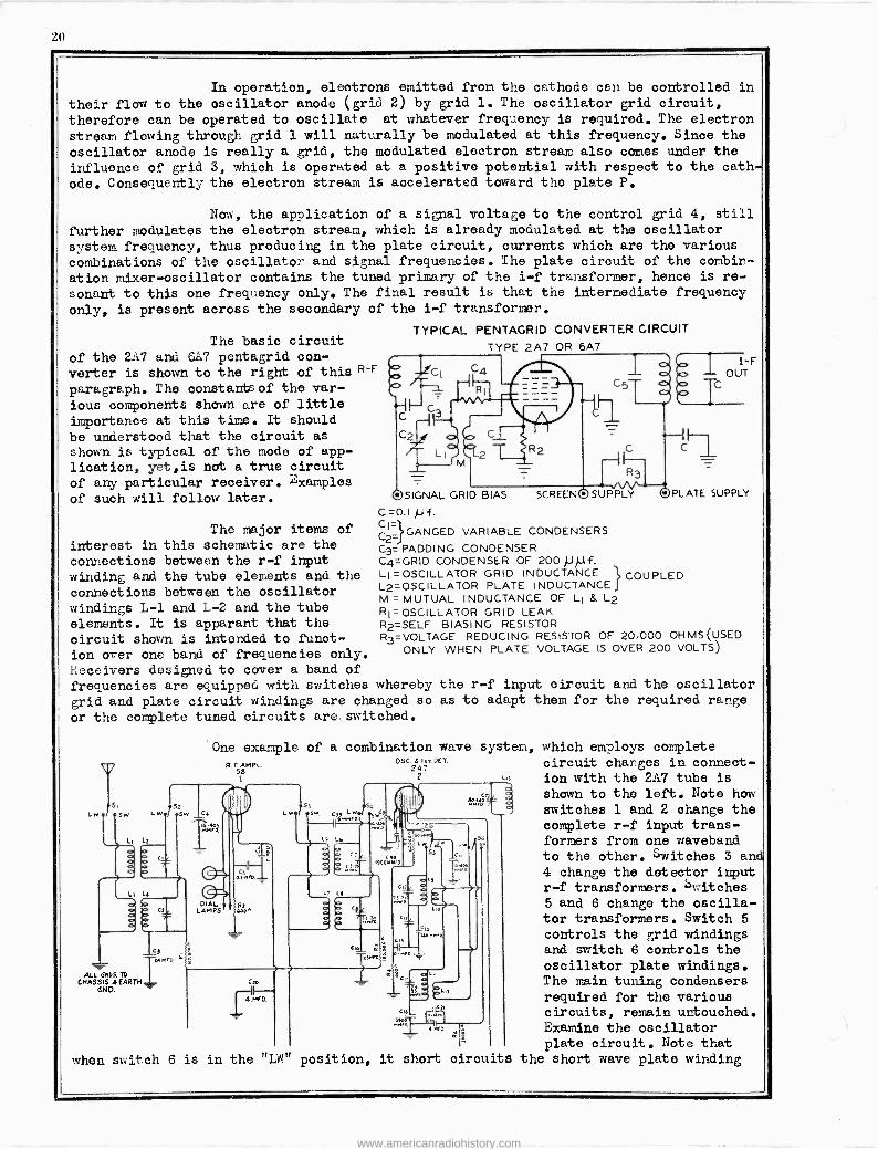
TYPICAL PENTAGRID CONVERTER CIRCUIT
R -F
The major items of
interest in this schematic are the
connections between the r -f input winding and the tube elements and the connections between the oscillator windings L-1 and L-2 and the tube elements. It is apparant that the circuit shown is intended to funct- ion over one band of frequencies only. Receivers designed to cover a band of frequencies are equipped with switches whereby the r -f input circuit and the oscillator grid and plate circuit windings are changed so as to adapt them for the required range
or the complete tuned circuits are switched.
TYPE 2A7 OR 6A7
@SIGNAL GRID BIAS SCREEN@SUPPLY OPLATE SUPPLY
C=00.I pf. C2_}GANGED VARIABLE CONDENSERS
C3=)))PADDING CONDENSER C4=GRID CONDENSER OF 200 pj.lf. Li =OSCILLATOR GRID INDUCTANCE } COUPLED L2=OSCILLATOR PLATE INDUCTANCE M = MUTUAL INDUCTANCE OF L1 & L2 R1 = OSCILLATOR GRID LEAK R2=SELF BIASING RESISTOR R3=VOLTAGE REDUCING RESISTOR OF 20.000 OHMS (USED
ONLY WHEN PLATE VOLTAGE IS OVER 200 VOLTS)
One example of a combination wave system, OSC. S Is, KT.
247 2 Li3
P R. 58ML.
i
rs, 52 LW.I .sW Lw.r.sw
L, L
C1
L L4
ALL 6105. TO
CHASSIS áEARTH SNP.
o (2
T.95990.
PEAL LAMPS
S
"+W (39 Lw I9*eM59
LS L6
o C
o O
9e5
5 OU
L, LI
o``` y 5r
Coo
) 4.MiD.
Cii
5 1:
C,5
qe
2"ó
;5- Ln
when switch 6 is in the "LW' position, it short circuits
which employs complete circuit charges in connect- ion with the 2A-7 tube is
shown to the left. Note how switches 1 and 2 change the complete r -f input trans- formers from one waveband to the other. Switches 3 an 4 change the detector input r -f transformers. Switches 5 and 6 change the oscilla- tor transformers. Switch 5
controls the grid windings and switch 6 controls the oscillator plate windings. The main tuning condensers required for the various circuits, remain untouched. Examine the oscillator plate circuit. Note that
the short wave plate winding
www.americanradiohistory.com
21
L-12, leaving the broadcast wave oscillator plate winding L-10 in the circuit. On the other hand when S6 is in the "S'A1' position, it short circuits the broadcast wave plate
winding L-10 and keeps L-12 in the circuit. The circuit being discussed is used in the RCA Victor 121,122 receiver. When the receiver is adjusted to the broadcast band, all
of the switches are simultaneously operated.
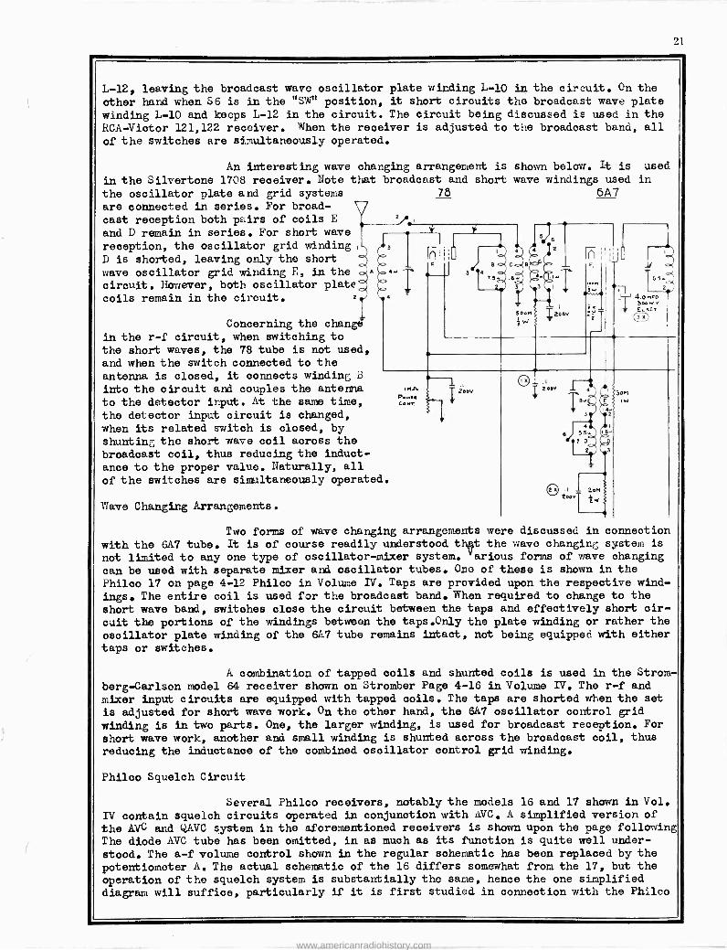
An interesting wave changing arrangement is
in the Silvertone 1708 receiver. Note that broadcast and short
the oscillator plate and grid systems 78
are connected in series. For broad- cast reception both pairs of coils E
and D remain in series. For short wave
reception, the oscillator grid winding, D is shorted, leaving only the short
wave oscillator grid winding E, in the circuit. however, both oscillator plate coils remain in the circuit. 2
Concerning the change in the r -f circuit, when switching to the short waves, the 78 tube is not used,
and when the switch connected to the antenna is closed, it connects winding ü
into the circuit and couples the antenna
to the detector input. At the same time,
the detector input circuit is changed, when its related switch is closed, by shunting the short wave coil across the broadcast coil, thus reducing the induct- ance to the proper value. Naturally, all
of the switches are simultaneously operated.
':save Changing Arrangements.
shown below. It is used wave windings used in
6A7
u
en 4.0 mg -0 bee
aer
Two forms of wave changing arrangements were discussed in connection
with the 6A7 tube. It is of course readily understood tie the wave changing system is
not limited to any one type of oscillator -mixer system. various forms of wave changing
can be used with separate mixer and oscillator tubes. Ono of these is shown in the Philco 17 on page 4-12 Philco in Volume IV. Taps are provided upon the respective wind-
ings. The entire coil is used for the broadcast band. When required to change to the short wave band, switches close the circuit between the taps and effectively short cir- cuit the portions of the windings between the taps.Only the plate winding or rather the
oscillator plate winding of the 6A7 tube remains intact, not being equipped with either taps or switches.
A combination of tapped coils and shunted coils is used in the Strom-
berg -Carlson model 64 receiver shown on Stromber Page 4-16 in Volume IV. The r -f and
mixer input circuits are equipped with tapped coils. The taps are shorted when the set is adjusted for short wave work. On the other hand, the 6A7 oscillator control grid winding is in two parts. One, the larger winding, is used for broadcast reception. For
short wave work, another and small winding is shunted across the broadcast coil, thus reducing the inAuctance of the combined oscillator control grid winding.
Philco Squelch Circuit
Several Philco receivers, notably the models 16 and 17 shown in Vol.
IV contain squelch circuits operated in conjunction with AVC. A simplified version of the AVC and Q,AVC system in the aforementioned receivers is shown upon the page following The diode AVC tube has been omitted, in as much as its function is quite well under-
stood. The a -f volume control shown in the regular schematic has been replaced by the
potentiometer A. The actual schematic of the 16 differs somewhat from the 17, but the operation of the squelch system is substantially the same, hence the one simplified diagram will suffice, particularly if it is first studied in connection with the Philco
www.americanradiohistory.com
22
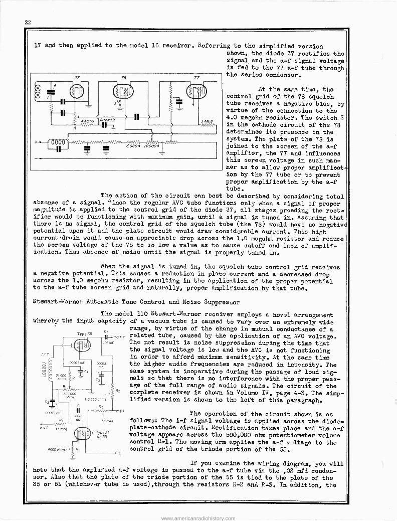
17 and then applied to the model 16 receiver. Referring to the simplified version shown, the diode 37 rectifies the signal and the a -f signal voltage is fed to the 77 a -f tube through the series condenser. 37
0000
MEGS
s'\;
002MF0
78 77
50000 10,000n
1 MEG -vwwv-
At the same time, the control grid of the 78 squelch tube receives a negative bias, by virtue of the connection to the 4.0 megohm tesistor. The switch S in the cathode circuit of the 78 determines its presence in the system. The plate of the 78 is joined to the screen of the a -f amplifier, the 77 and influences this screen voltage in such man- ner as to allow proper amplificat- ion by the 77 tube or to prevent proper amplification by the a -f tube.
The action of the circuit can best be described by considering total absence of a signal. Since the regular AVC tube functions only when a signal of proper magnitude is applied to the control grid of the diode 37, all stages prceding the rect- ifier would be functioning with maximum gain, until a signal is tuned in. Assuming that there is no signal, the control grid of the squelch tube (the 78) would have no negative potential upon it and the plate circuit would draw considerable current. This high current drain would cause an appreciable drop across the 1.0 megohn resistor and reduce the screen voltage of the 78 to so low a value as to cause cutoff and lack of amplif- ication. Thus absence of noise until the signal is properly tuned in.
When the signal is tuned in, the squelch tube control grid receives a negative potential. This onuses a reduction in plate current and a decreased drop across the 1.0 megohm resistor, resulting in the application of the proper potential to the a -f tube screen grid and naturally, proper amplification by that tube.
Stewart -Warner Automatic Tone Control and Noise Suppressor
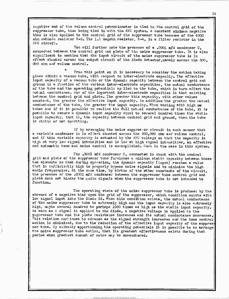
The model 110 Stewart darner receiver employs a novel arrangement whereby the input capacity of a vacuum tube is caused to vary over an extremely wide
range, by virtue of the change in mutual conductance of a Type 55 related tube, caused by the application of an AVC voltage.
o.mf. The net result is noise suppression during the time that the signal voltage is low and the AVC is not functioning
`T in order to afford maximum sensitivity. At the same time 000z5mf coos, the higher audio frequencies are reduced in intensity. The
same system is inoperative during the passage of loud sig- nals so that there is no interference with the proper pass- age of the full range of audio signals. The circuit of the
R' complete receiver is shown in Volume IV, page 4-3. The simp- lified version is shown to the left of this paragraph. 2'
C R3
.00025m4 .coo, ' The operation of the circuit shown is as
R4 mf me9 follows: The i -f signal voltage is applied across the diode- mog __ plate -cathode circuit. Rectification takes place and the a -f A.v.c
500,000 ohms
110.000 ohms
TYPO voltage appears across the 500,000 ohm potentiometer volume control R-1. The moving arm applies the a -f voltage to the control grid of the triode portion of the 55.
If you examine the wiring diagram, you will note that the amplified a -f voltage is passed to the a -f tube via the ,02 mfd conden- ser. Also that the plate of the triode portion of the 55 is tied to the plate of the 35 or 51 (whiohever tube is used),through the resistors R-2 and R-3. In addition, the
www.americanradiohistory.com
z:c
negative end of the volume control potentiometer is tied to the control grid of the suppressor tube, thus being tied in with the AVC system. A constant minimum negative bias is also applied to the control grid of the suppressor tube because of the 4000 ohm. cathode resistor R-5. The 1.1 megohm resistor, R-4, is a filter resistor in the AVC circuit.
You will further note the presence of a .0001 mfd condenser C, connected between the control grid and plate of the noise suppressor tube. It is also significant to mention that the input circuit of the noise suppressor tube is in effect shunted across the output circuit of the diode deteetor,namely across the 500, 000 ohm a -f volume control.
From this point on it is necessary to consider the aotion taking place within a vacuum tube, with respect to inter -electrode capacity. The effective input capacity of a vacuum tube or the dynamic capacity between the control grid and ground is a function of the various inter -electrode capacities, the mutual conductance of the tube and tho operating potentials applied to the tube, which in turn affect the mutual conductance. One of the important inter -electrode capacities is that existing between the control grid and plate. The greater this capacity, with other -values constant, the greater the effective input capacity. ln addition the greater the mutual conductance of the tube, the greater the input capacity. When working with high mu tubes and if it is possible to realize the full mutual conductance of the tube, it is
possible to secure a dynamic input capacity equal to several hundred times the static input capacity, that is, the capacity between control grid and ground, when the tube is static or not operating.
If by arranging the noise suppres or circuit in such manner that a variable condenser is in effect shunted across the 500,000 ohm a -f volume control, and if this variable capacity is actuated by the AVC voltage so that the capacity is high at very low signal intensities and is low at high signal intensities, an effective and automatic tone and noise control is accomplished. Úuch is the case in this system.
The .0001 mfd condenser C, connected in shunt with the control grid and plate of the suppressor tube furnishes a minimum static capacity between these two elements so that during operation, the dynamic capacity (input) reaches a value that is sufficiently high to properly bypass noise signals and to minimize the high audio frequencies. At the same time, by virtue of the other constants of the circuit, the presence of the .0001 mfd condenser between the suppressor tube control grid and plate does not hinder the audio signals when the suppressor tube is not intended to function.
The operating state of the noise suppressor tube is produced by the absence of a negative bias upon the grid of the suppressor, which condition exists with low signal input into the diode 55. When this condition exists, the mutual conductance of the noise suppressor tube is extremely high and the input capacity is also extremely high, maybe several hundred to perhaps 1000 times as high as the static input capacity. As soon as a signal is applied to the diode, a negative voltage is applied to the suppressor tube and its plate resistance increases and its mutual conductance decreases. This relation continues to advance as the signal strength increases and the tone control action is minimized, due to the reduction of the effective input capacity of the suppres sor tube. By suitably apportioning the operating potentials it is possible to so arrange the noise suppressor tube action, that its greatest effectiveness exists during that period when greatest amount of noise may be encountered.
www.americanradiohistory.com

e
www.americanradiohistory.com