foxwoods engineering material equipment standards
TRANSCRIPT
FOXWOODS ENGINEERING DEPARTMENT MATERIAL EQUIPMENT STANDARDS
1
FOXWOODS ENGINEERING MATERIAL EQUIPMENT
STANDARDS
REVISED: 5/25/2017

FOXWOODS ENGINEERING DEPARTMENT MATERIAL EQUIPMENT STANDARDS
2
FOXWOODS ENGINEERING MATERIAL & EQUIPMENT STANDARDS
TABLE OF CONTENTS
SECTION 1 – LOCKS, HARDWARE, FLOORING, WALLCOVERINGS & CEILINGS 1.1 Locks – Door Hardware (Pg. 3) 1.2 Cabinet Hardware (Pg.4) 1.3 Carpeting (Pg. 4) 1.4 Flooring (Pg. 4-5) 1.5 Paint – Back of House (Pg. 5) 1.6 Ceilings (Pg. 5) SECTION 2 – KITCHEN EQUIPMENT 2.1 Kitchen Cooking Appliances (Pg. 6-8) 2.2 Exhaust Hood Systems (Pg. 8) 2.3 Utility Services (Pg. 8-9) 2.4 Coolers/Freezers (Pg. 9-10) 2.5 Refrigeration System (Pg. 10-Ref. Section 4) SECTION 3 – ELECTRICAL EQUIPMENT 3.1 Electrical Equipment (Pg. 11-24) 3.2 Design Standards (Pg. 24-28) SECTION 4 – HVAC EQUIPMENT 4.1 HVAC Equipment (Pg. 29-32) 4.2 HVAC Design Standards (Pg. 32-35) 4.3 General Building System Monitoring and/or Control Points (Pg. 35-37) 4.4 Building Monitoring Standards (Pg. 37) 4.5 Refrigeration Systems (Pg. 37-42) SECTION 5 – PLUMBING 5.1 Plumbing/Steam (Pg. 43-44) 5.1.1 Design Standards (Pg. 44-45) 5.2 Steam/Plumbing Replacement Parts (Pg. 44-45) 5.3 Drainage (Pg. 46) 5.4 Domestic Water (Pg. 46-47) 5.5 Design Standards (Pg. 47-48) 5.6 System Installation Requirements (Pg. 47-53) SECTION 6 – POOLS/SPAS/WATER FEATURES 6.1 Equipment and Material – Pool/Spa & Water Features including Pump Rooms (Pg. 54) 6.2 Material/Equipment & Design for all Pools/Spas & Water Features including related Pump Rooms
& Chemical Rooms (Pg. 54-74) SECTION 7 – FIBEROPTIC EQUIPMENT 7.1 Design Standards (Pg. 75)

FOXWOODS ENGINEERING DEPARTMENT MATERIAL EQUIPMENT STANDARDS
3
SECTION 1 – LOCKS, HARDWARE, FLOORING, WALL COVERINGS & CEILINGS 1.1 LOCKS – DOOR HARDWARE A. Sargent Mortise Locks: 8200 Series
1. 8205 – Office function (New style incorporates storeroom, passage, classroom
functions)
2. 8204 – Storeroom function
3. 8215 – Passage function
4. Finishes: 26D, 03, trim LNL (lever handles) B. Key Cylinders: Sargent LA 6 pin (currently investigating better system) or Keso R/C
C. Bored Lever Cylindrical Handles (Sargent)
1. 28-10G04 – Storeroom
2. 28-10G05 – Office
3. 28-10415 – Passage
4. Finish: 26D – 03
D. Bored Lever Cylindrical Lock (Patron Bathrooms) (update:2017)
1. Arrow RL Series Grade 2- Privacy 26D finish
E. Exit Devices
1. 8500 Narrow Line Design: 04-26D-03 finish, ETL trim
2. 8700 Surface Vertical Rod: 26D-03-04 finish, ETL trim
3. 8800 Rim Exit Device: 26D-03-04 finish, ETL trim
4. 8600 Concealed Vertical Rod Devices: 26D-03-04 finish, ETL trim
F. Combination Locks
1. KABA / Ilco: S/I 1021B-26D or 03 finish (all Simplex with I/C cores)
G. Hotel Villas/ Standard Rooms/Suites (Update:2017)
1. Baldwin: BA5450 series, privacy and passage, 03 finish - Villias
2. Arrow: GL Series Cylindrical Lock- Privacy 03 or 26D finish- Rooms/Suites

FOXWOODS ENGINEERING DEPARTMENT MATERIAL EQUIPMENT STANDARDS
4
H. Door Closures
1. Sargent
2. LCN
For all temporary construction walls use: Construction locks and keying. The identified locksets for swing type doors (see above) are to be used with Keso construction master removable cores installed. Contact Foxwoods Engineering Locksmith Department for additional information. 1.2 CABINET HARDWARE
A. Coin Carts, Lockers and Slot Bases: Medeco: ME60 Series, 26D finish
B. Door Locks: (Olympus) OL721-DR Polished brass or satin chrome finishes (all with I/C core lock
bodies) C. Draw Locks: (Olympus) OL721-DW Satin chrome or polished brass finishes (all with I/C core lock
bodies) D. Slot Bases & Machine Outer Door Locks: Medeco Dura Cam II, Removable Core Lock
1.3 CARPETING (UPDATE: 2017) A. Carpet/Squares: Shaw, Charisma, pattern # 59561,color #979, Artistic (Back of house, offices,
halls, etc.) B. Carpet/Squares: Lees, Attribute, pattern #DL456, color #467 Hummingbird (Café 1 & 2)
C. Treadmore #2500 (Carpet pad) (Front of house)
D. Casino Floor: Axminster 10row / 7 pitch woven carpet
E. Hotel guest rooms, halls: Tufted carpet
F. Cafeterias, back of house, offices, etc.: Tufted carpet / LVT
G. Coin Cages, Redemption Areas, etc.: Carpet squares
H. Design Standard:
1. Padding should be all the same weight around 33lb. Density in all areas except hotel
rooms (Treadmore Full-House). Foxwoods is presently using (4) types of padding. 2. Type and composition of carpet and application to be endorsed by Engineering prior
to design stage. 1.4 FLOORING (TILE, STONE, PAVERS AND VCT)
A. Quarry Tile; 1/2" kitchens
B. Ceramic / Porcelain Tile; Restrooms and Bathrooms
C. Brick Pavers; 3 3/8 x 7 5/8 x 1/2" mixed blend (Front of the House)
D. Engineered Quartz 12”x12” (Front of the House)

FOXWOODS ENGINEERING DEPARTMENT MATERIAL EQUIPMENT STANDARDS
5
E. Stone (Front of the House)
F. Granite (Front of the House) G. Marble (light to medium traffic)
H. Slate 1/2" variegated, pattern #5 (Front of the House)
I. Solid Surface (simulated stone products)
J. VCT (Back of the House); Armstrong - Imperial Texture pattern # 51899
K. Vinyl Base (Back of the House); Burke Mercer - 4" vinyl rubber-base Color 101 Black
L. Stair Treads (Back of the House); Roppe-Festa, Style 98; Color 100 Black
M. Dur-A-Flex HF for kitchen hot line
N. Dur-A-Flex MD for serving line
1.5 PAINT - BACK-OF-HOUSE
A. Benjamin Moore, match # 981 Aquavelvet Eggshell (walls)
B. Benjamin Moore, match #981 Impervex High Gloss (doors and frames) 1.6 CEILINGS
A. Suspended (back of house):
1. USG 135 (2'x4'); USG 131 (2'x2');
2. USG 3270 Gypsum, Vinyl (2'x4'); USG 3260 Gypsum, Vinyl (2'x2')
FOXWOODS ENGINEERING DEPARTMENT MATERIAL EQUIPMENT STANDARDS
6
SECTION 2 – KITCHEN EQUIPMENT (No Changes 2017)
2.1 KITCHEN COOKING APPLIANCES A. Preferred Manufacturers List
1. Ranges
a. Jade Range b. Garland c. US Range
2. Broilers
a. Jade b. Magi-kitchen c. Montaque
3. Griddles
a. Keating b. Magi-kitchen
4. Deep Fat Fryers
a. Pitco b. Frymaster
5. Ovens
a. Convection Ovens – Blodget & Jade Range b. Bakery Rack Ovens – Revent, Baxter, Bakers Aid & Adamatic c. Pizza Oven Electric – Garland d. Pizza Ovens – Blodget, Bakers Aid & Middleby Marshall e. Combi Ovens – Rationale & Blodget f. Rotary Ovens – Cutler
6. Warming Permanent Installation
a. Soup Wells – APW & Wells b. Steam Wells – APW, Wells or custom fabricated direct steam feed
7. Table Top Warmers
a. APW b. Wells c. Star
8. Rolling Warmers
a. Carter Hoffman b. Alto Shaam
9. Portable Heat Lamps
a. Hatco b. Wells c. APW d. Star
10. Mixers
a. Hobart b. Bakers Aid
11. Slicers
a. Hobart
FOXWOODS ENGINEERING DEPARTMENT MATERIAL EQUIPMENT STANDARDS
7
b. Globe c. Berkel
12. Dish/Utensil Washers
a. Hobart
13. Microwaves a. Hobart b. Amana
14. Direct Steam Kettles
a. Groen b. Vulcan
15. Self Contained Steam Kettles
a. Groen
16. Steamers table top electric a. Groen-open broiler pressure less tank
17. Chitwood Smokers
a. Jade
18. Woks a. Town b. Oriental Smokers
19. Tilt Skillets
a. Groen B. Substitutions: This listing is not all inclusive and as such, any equipment type not noted here or
substitutions of equipment built by manufacturers other than those listed shall be submitted to the Engineering Department for review and approval. The review will consist of verification of UL listing and a general investigation of reliability, serviceability and availability of service support and repair parts
C. Installation Requirements
1. All equipment shall be installed in accordance with the manufacturer’s installation
requirements, including, but not limited to the minimum clearances to surrounding equipment, combustible materials and walls or other obstruction
2. All equipment installations shall meet or exceed the safety requirements of the
current published editions of each of the following: a. NFPA 96 – Standard for the Ventilation Control and Fire Protection of
Commercial Cooking Operations b. NFPA 54 – National Fuel Gas Code c. NFPA 70 – National Electrical Code d. NFPA 211 – Standard for Chimneys, Fireplaces, Vents and Solid Fuel
Appliances e. OSHA 29 CFR 1910 – General Safety Standard
1) OSHA 29 CFR 1910.263 – Safety Standards for Bakery Equipment
3. All equipment other than permanently installed Bakery, Production or Table Top equipment shall be supplied with castors and a restraint system to maintain required fire suppression coverage when in use
4. All gas appliances and other equipment producing grease laden vapors shall be
installed under a Type I UL Listed Hood
FOXWOODS ENGINEERING DEPARTMENT MATERIAL EQUIPMENT STANDARDS
8
5. All direct steam, electric or other equipment not listed under UL 197 shall be installed
under a minimum of a Type II UL Listed Hood
6. Only those cooking appliances listed under UL 197 or an equivalent standard for reduced emission shall be permitted to be installed with no hood
2.2 EXHAUST HOOD SYSTEMS A. Preferred Manufacturers
1. Gaylord Industries, Ventmaster, Captive Aire
2. Substitutions of non-preferred manufacturers shall be submitted to the Engineering
Department and Fire Marshall’s Office for review and approval. The review will consist of verification of UL Listing and general investigation of reliability, serviceability and availability of service support and repair parts
B. Grease Removal Hoods
1. All Grease Removal Hoods shall be either of a Fixed Baffle Water Wash design or of
a suitable technological design to minimize grease accumulation in associated duct work and fans
2. Any hood consisting of a filter technology other than those currently in use at
Foxwoods (i.e. – Fixed Baffle Water Wash or UV Light filtered) shall be submitted to the Engineering Department and Fire Marshall’s Office for review. This review shall consist of verification of UL Listing and general investigation of reliability, serviceability, availability of service and repair part support, and proven effectiveness of grease removal
C. Installation Requirements
1. All Kitchen Hood installations, regardless of type, shall meet or exceed the
requirements of the current published editions of: a. NFPA 96 – Standard for Ventilation Control and Fire Protection of
Commercial Cooking Operations. b. NFPA 70 – National Electrical Code c. NFPA 211 – Standard for Chimneys, Fireplaces, Vents and Solid Fuel
Appliances d. Section IV: HVAC Mechanical of this Standard e. Manufacturers installation requirements
2. All Hood installations shall include provisions to access and service components located above the ceiling line, including but not limited to, catwalks, and fall protection tie-off points as required by 29 CFR 1910.66 Appendix C – Personal Fall Arrest Systems
2.3 UTILITY SERVICES
A. Electrical Services
1. All electrical services equipment and connections shall meet or exceed the
requirements of the current published editions of: a. NFPA 70 – National Electrical Code b. NFPA 70E Electrical Safety in the workplace (update:2017) c. NFPA 96 – Standard for Ventilation Control and Fire Protection of Commercial
Cooking Operations d. 29 CFR 1910.263 – OSHA Standard for Bakery Equipment (where applicable)

FOXWOODS ENGINEERING DEPARTMENT MATERIAL EQUIPMENT STANDARDS
9
e. Section III: Electrical Mechanical of this Standard f. Manufacturers installation requirements
2. All electrical circuits for equipment located under hoods shall be shunt tripped or
otherwise controlled such that all circuits are de-energized in the event of a Fire Suppression Control System Alarm condition
3. All electrical circuits terminated by a service outlet shall have the outlet installed such
that it meets the standards and requirements of “Spray Tight” and will include In Use outlet covers
4. All kitchen installations shall include an Emergency Stop located within the expected
path of Egress and clearly identified. This Emergency Stop shall activate the shunt trip, or isolation circuit, required in Section 2.3.A.2 of this standard, as well as initiate a minimum of a “Trouble” alarm in the Fire Suppression System and building Fire alarm system
B. Gas Service
1. All Gas Services equipment and connections shall meet or exceed the requirements
of the current published editions of: a. NFPA 54 – National Fuel Gas Code b. NFPA 96 – Standard for Ventilation Control and Fire Protection of Commercial
Cooking Operations c. Section V: Plumbing/Steam mechanical of this Standard
2. All gas equipment shall be connected to the existing Natural Gas Service
installations. No portable propane or other manufactured gas tanks shall be in use in any permanently constructed kitchen
3. All gas equipment shall be connected via a UL Listed/AGA accepted flexible hose
and disconnect device rated for commercial service. Only permanently installed, non-movable equipment (i.e. – Bakery style ovens) shall be piped directly to a gas source
4. All gas installations shall include AGA accepted/UL Listed shut off valves located
within the gas main and at each appliance supply. There shall be a minimum of 6” (inches) of Straight pipe on both the supply and outlet sides of each shut off valve to allow for adequate lock out in accordance with 29 CFR 1910.147. An appropriate Lock out device shall be supplied for any valve installed other than the standard “Ball” valve
5. All Gas Main headers shall include an electrically operated solenoid safety shutoff
valve that is energized open, normally closed. This valve shall be supplied electrical power such that gas is shut off in the event of a Fire Suppression Activation and/or activation of the Emergency Stop Switch required in Section 2.3.A.4 of this Standard
C. Plumbing Services
1. Reference Section 5: Plumbing/Steam mechanical
2. All steamers shall be installed with a floor drain in close proximity. No gas fired
boilers shall be permitted to have a floor drain installed directly under the unit 2.4 COOLERS / FREEZERS A. Boxes – W.A Brown or Bally (reference Section IV, 4.1)
1. Freezer floors heated (Designer to evaluate location and operating conditions)
FOXWOODS ENGINEERING DEPARTMENT MATERIAL EQUIPMENT STANDARDS
10
2. Floors are not to be prefabricated. Floor covering to be Quarry Tile
3. Refrigeration equipment will be:
a. Water-cooled with Copeland Semi-Hermetic compressor with an accessible tube and shell water cooled condenser
b. Chilled water supply, returns and drains to have shut off valves for each water cooled condenser and drain
4. Control Defrost time-clocks
B. Ice Machines: Manitowoc: Water cooled
1. Ice Bins: Follet – Stainless Steel
2. Water Filters – Everpure
Note: No stackable ice machines Note: Ice bins no higher than 6’
2.5 REFRIGERATION SYSTEM
A. Reference Section 4
FOXWOODS ENGINEERING DEPARTMENT MATERIAL EQUIPMENT STANDARDS
11
SECTION 3 – ELECTRICAL EQUIPMENT 3.1 Electrical Equipment Design for any new equipment or major remodel to include the latest NFPA 70E standards; current Edition Standard for electrical safety in the workplace
• Arc flash evaluation
• Arc Flash calculations
• Short circuit evaluation
• Short circuit coordination
• NFPA 70E Labeling requirement
• Safety related work practices
• Safety related maintenance requirements
• Safety requirements for special equipment A. Switchboards
1. Acceptable Vendors and Products
a. General Electric – All Phases except 3B and 3C 1) Spectra Series Switchboards
b. Square D – Phases 3B and 3C ONLY 1) QED-2 Power-Style Switchboards
2. General Requirements
a. Switchboards shall be provided with front and back access panels. Where space does not permit, switchboards shall be provided with front access and rear alignment
b. Switchboards enclosures shall be NEMA 1 for indoor applications and NEMA 3R for outdoor or harsh environment applications
c. Switchboard sections shall have open bottoms and removable top plate(s) to install conduit
d. Switchboards shall be UL listed e. Switchboards that are series rated to short circuit requirements shall be
appropriately labeled. All main and emergency switchboards shall be rated for a minimum of 65kAIC
f. CBSarcSafe operators or motor operated breakers to be installed on any breakers above category 3 arcflash. (update:2017)
g. All covers shall be fastened by hex head bolts h. Hinged doors shall be provided over metering compartments and individually
mounted device compartments. Doors shall have concealed hinges and be fastened by hex head bolts
i. Switchboard current ratings, including all devices, shall be based on a maximum ambient temperature of 25°C per UL Standard 891. With no derating required, temperature rise of switchboards and devices shall not exceed 65°C in a 25°C ambient environment
j. Switchboard service entrance sections shall comply with UL Service Entrance requirements including a UL service entrance label, incoming line isolation barriers, and a removable neutral bond to switchboard ground for solidly grounded-wye systems
k. The group mounted feeder breaker and/or main devices within switchboards shall be circuit breakers only. Mounting of the group mounted devices shall be by bolted connection

FOXWOODS ENGINEERING DEPARTMENT MATERIAL EQUIPMENT STANDARDS
12
l. Bus bars shall be silver plated copper. The bus bars shall have sufficient cross sectional area to meet UL891 temperature rise requirements through actual tests
m. Bus bars shall be mounted on high impact, non-tracking insulated supports. Joints in the vertical bus are not permitted
n. Bus bars shall be braced to withstand mechanical forces exerted during short circuit conditions and shall be rated for a minimum of 65kA RMS SYM
o. Ground bus shall be sized to meet UL 891. Ground bus shall extend the full length of the switchboard
p. A-B-C bus arrangement (left to right, top to bottom, front to rear) shall be used throughout to assure convenient and safe testing and maintenance. Where special circuitry precludes this arrangement, bus bars shall be labeled
q. Main horizontal bus bars shall be fully rated and arranged for future extension r. Switchboards installed outdoors or in areas not serviced by building HVAC,
space heaters shall be provided to maintain switchboard temperature within the manufacturer’s limits. A failure of the space heaters shall be communicated to the building management system
s. Future Provisions: All unused spaces provided, unless otherwise specified, shall be fully equipped for future devices, including all appropriate connectors and mounting hardware
t. Show the entire single line switchboard bus work, as depicted on the factory record drawing, on an engraved laminated plastic (Gravoply) nameplate. The nameplate shall be at least .0625 inch thick and located at eye level on the front cover of the switchboard incoming service section
u. Lightning arrestors shall be provided on the service entrance conductors at the point of entry into all main switchboards. Connection of the lightning arrestors shall be directly to the bus bars with a means of disconnect for replacement. If fuses are used as the disconnect, a means of visual verification of fuse integrity shall be provided
v. TVSS units shall be installed on all main switchboards downstream of the incoming line circuit breaker. The TVSS units shall be capable of being isolated from the switchboard for replacement without the need to de-energize the switchboard. TVSS units shall be provided with a visual means of verification of operation. Dual listed TVSS units that provide lightning protection and transient surge protection are acceptable so long as they meet the applicable UL requirements for each application
w. Main and Emergency Switchboards shall be provided with front panel meters depicting phase current and voltage. In addition, a multifunction digital metering package shall be provided to monitor phase and line current, phase and line voltage, KW, KVAR, KVA, power factor, and frequency as a minimum. This metering package shall be capable of communicating with the Building Management system
B. Panel Boards
1. Acceptable Vendors and Products a. General Electric – All Phases except 3B and 3C
1) A Series Panelboards up to 600A 2) Spectra Series Panelboards greater than 600A
b. Square D – Phases 3B and 3C ONLY 1) NF or NQOD Panelboards up to 600A 2) I-Line Panelboards greater than 600A
2. General Requirements
a. Panelboards fed from power sources not located in the same room shall utilize a main circuit breaker as the local disconnecting means
FOXWOODS ENGINEERING DEPARTMENT MATERIAL EQUIPMENT STANDARDS
13
b. Bus bars shall be current density rated or meet UL 67 temperature rise limits through actual tests. All bus bars shall be copper and silver plated
c. Circuit breakers shall be designed for removal or replacement without disturbing adjacent protective devices and without removing main bus and/or branch circuit connections
d. Panelboards shall have three flat, stacked, vertically aligned bus bars. The vertical bus shall be a single bar. Joints are not permitted in the vertical bus
e. Bus bars shall be phase sequenced and rigidly supported by high impact resistant, insulated bus supporting assemblies to prevent vibration or short circuit mechanical damage
f. Panelboards for services of 400A and greater shall be rated for a minimum of 65kA AIC
g. Neutral bus shall be fully rated and able to be located in either corner of the enclosure at line end to facilitate conductor termination. A 200% rated neutral bus shall be installed for all panelboards
h. All solderless terminations shall be suitable for copper UL listed wire or cable and shall be tested and listed in conjunction with appropriate UL standards
i. Ground wire terminations shall be provided as an optional kit for installation by the panelboard installer without voiding the UL label
j. Panelboard covers shall be supplied with a full piano hinge such that opening of the panelboard cover does not require full removal
k. Panelboards which feed computer and other sensitive loads shall be supplied with TVSS units independent of the upstream TVSS unit on the main switchboard
l. Distribution type panelboards shall have a main circuit breaker installed. This type of panelboard shall be supplied with a means to measure voltage, current, KW, KVA, KVAR and power factor from a remote data acquisition system. In addition, the main circuit breaker should be outfitted with auxiliary contacts to allow monitoring of the breaker position
m. All panel boards that are for tenant spaces will require remote metering. All panels and/or main feed will require an Class 5000 smart meter ( E-Mon www.emon.com ) (Update:2017)
C. Circuit Breakers
1. Acceptable Vendors and Products a. General Electric
1) All Phases except 3B and 3C b. Square D
1) Phases 3B and 3C ONLY
2. General Requirements a. Circuit breaker faceplate shall list current rating, UL and IED certification
standards and AIC ratings b. All circuit breakers to be installed in panelboards and switchboards shall be
new. Circuit breakers relocated from existing panelboards are also acceptable c. Minimum 20A in all Lighting/Distribution Panels. 15 A circuit breakers are not
to be used on-site d. All panelboards shall contain 42 circuits unless space considerations do not
permit e. Circuit breakers shall be UL listed for reverse connection without restrictive
line or load markings. Circuit breakers shall be able to mount in any operating position
f. New panelboards shall be provided with a minimum of 25% spare capacity for future installation
g. Circuit breakers shall carry the same AIC rating as the panel to which they will be installed. 65kA AIC circuit breakers are recommended where possible

FOXWOODS ENGINEERING DEPARTMENT MATERIAL EQUIPMENT STANDARDS
14
Distribution type panelboards and switchboards rated 400A through 1200A shall use breakers rated for 65kA AIC with 1 set of Form C contacts. Spectra Series circuit breakers with the optional set of contacts should satisfy this requirement.
h. 3-pole breakers with frame ratings greater to or greater than 150A shall utilize
digital true RMS sensing trip units and a rating plug to determine trip setting. The use of rating plugs for circuit breakers of frame sizes smaller than 150A is recommended where space permits
i. Main Circuit breakers shall be used for all applications where the main power source is not within view of the panelboard or located in the same electric room
3. Specific Requirements
a. Molded Case Breakers 1) Thermal-Magnetic molded case circuit breakers may be utilized for
branch circuit loads rated 150A and below 2) Circuit breakers with trip ratings greater than 250 amperes to 1000
amperes shall be UL listed as 100% continuous duty rated b. Insulated Case Breakers
1) Circuit Breakers for applications greater that 1200A shall use insulated case type breakers (GE - Power Break or Power Break II circuit Breakers with MicroVersa Trip Plus trip units with one set of Form C contacts or Square D Micrologic with one set of Form C contacts). The interrupting mechanism shall be arc chutes
2) Breakers shall be designed for a maximum five cycle closing time. Breakers shall be trip free at all times. Common tripping of all poles shall be standard
3) Breakers shall be rated to carry 100% of their frame ampacity continuously
4) All insulated case circuit breakers shall be provided with true RMS sensing digital trip circuitry and a rating plug, if applicable
5) Insulated case circuit breakers shall be supplied with at least 1 Form C contact for connection to the Owners Building Management System
c. Trip Units 1) Circuit breakers equipped with only a rating plug shall have
adjustable instantaneous current settings. The instantaneous current setting selector shall be front mounted for ease of access
2) Circuit breakers equipped with digital trip units shall be supplied with Long Time pickup, Long Time Delay, Short Time pickup, Short Time delay, and Instantaneous trip settings. Ground fault pickup and delay trips shall be provided based upon the installation
3) Adjustment of the digital trip unit settings shall be possible with the breaker closed and supplying the load
4) All new circuit breakers installed on site shall be supplied with Time-Current curves that shall be part of the design documentation submitted with the project. These curves will be subject to review and approval by the Facility Electrical Engineer
5) All new circuit breakers shall be reviewed by the Facility Electrical Engineer for impact on coordination and arc flash levels at the panelboard/switchboard. The Facility Electrical Engineer has final approval over all new circuit breakers installed in the facility, without exception
D. Transformers
1. Acceptable Vendors and Products a. General Electric – All Phases except 3B and 3C

FOXWOODS ENGINEERING DEPARTMENT MATERIAL EQUIPMENT STANDARDS
15
b. Square D – Phases 3B and 3C ONLY
2. General Requirements
a. All new transformers shall be rated for non-linear loads and shall be of the low harmonic type. Energy star transformers shall be supplied where possible
b. Indoor transformers shall be dry type with windings rated for 150°C temperature rise, minimum
c. Transformers 15kVA and larger shall have a minimum of 6 - 2.5% full capacity primary taps for 480V primaries and a minimum of 2 - 5% full capacity taps for 208V primaries. Exact voltages and taps to be as designated on the plans or the transformer schedule
d. The maximum temperature of the top of the enclosure shall not exceed 50 C rise above a 40 C ambient
e. K-Factor rated transformers shall have an impedance range of 3% to 6%, and shall have a minimum reactance of 2% in order to help reduce neutral current when supplying loads with large amounts of third harmonic current
f. All transformer windings shall be copper. Aluminum windings are not acceptable
E. Transfer Switches
1. Acceptable Vendors and Products
a. Russelectric b. ASCO
2. General Requirements
a. Transfer switches shall be closed transition type with provisions for manual transfer and reset
b. Transfer switches shall be capable of remotely starting the associated Emergency Generator, transferring load for weekly load test, transferring back to normal power and securing the Emergency Generator. This function shall be programmable and field adjustable
c. The transfer switch shall be capable of being removed from service for maintenance without interruption of power to the loads
d. Local indication shall be provided to indicate power available and transfer switch position
e. Communications capability shall be provided to ensure transfer switch status can be interfaced with the Foxwoods BMSO system. The ability to override and control the transfer switch from the Foxwoods BMSO is also required
f. The transfer switch shall be electrically operated and mechanically held. The electrical operator shall be a momentarily energized, solenoid mechanism. Main operators which include overcurrent disconnect devices, linear motors or gears shall not be acceptable
g. All transfer switch sizes shall use only one type of main operator for ease of maintenance and commonality of parts
h. The switch shall be positively locked and unaffected by momentary outages, so that contact pressure is maintained at a constant value and contact temperature rise is minimized for maximum reliability and operating life
i. Transfer switches shall be provided with a means of monitoring voltage, current, KW, KVA, KVAR and power factor for both normal and emergency power supplies and the load. The transfer switch shall have the capability of communicating this information to the Building Management System or another data acquisition system for monitoring, trending and load shedding

FOXWOODS ENGINEERING DEPARTMENT MATERIAL EQUIPMENT STANDARDS
16
j. All main contacts shall be silver composition. Switches rated 600 amperes
and above shall have segmented, blow-on construction for high withstand and close-on capability and be protected by separate arcing contacts
k. Inspection of all contacts shall be possible from the front of the switch without disassembly of operating linkages and without disconnection of power conductors. Switches rated 600 amps and higher shall have front removable and replaceable contacts. All stationary and moveable contacts shall be replaceable without removing power conductors and/or bus bars
l. Designs utilizing components of molded-case circuit breakers, contactors, or parts thereof, which are not intended for continuous duty, repetitive switching or transfer between two active power sources are not acceptable
m. Where neutral conductors are to be solidly connected as shown on the plans, a neutral conductor plate with fully rated AL-CU pressure connectors shall be provided
n. A two-way bypass-isolation switch shall provide manual bypass of the load to either source and permit isolation of the automatic transfer switch from all source and load power conductors. All main contacts shall be manually driven
o. Power interconnections shall be silver-plated copper bus bar. The only field installed power connections shall be at the service and load terminals of the bypass-isolation switch. All control interwiring shall be provided with disconnect plugs
p. Separate bypass and isolation handles shall be utilized to provide clear distinction between the functions. Handles shall be permanently affixed and operable without opening the enclosure door. Designs requiring insertion of loose operating handles or opening of the enclosure door to operate are not acceptable
q. Bypass to the load-carrying source shall be accomplished with no interruption of power to the load (make before break contacts). Designs which disconnect the load when bypassing are not acceptable. The bypass handle shall have three operating modes: "Bypass to Normal," "Automatic," and "Bypass to Emergency." The operating speed of the bypass contacts shall be the same as the associated transfer switch and shall be independent of the speed at which the manual handle is operated. In the "Automatic" mode, the bypass contacts shall be out of the power circuit so that they will not be subjected to fault currents to which the system may be subjected
r. The isolation handle shall provide three operating modes: "Closed," "Test," and "Open." The "Test" mode shall permit testing of the entire emergency power system, including the automatic transfer switches with no interruption of power to the load. The "Open" mode shall completely isolate the automatic transfer switch from all source and load power conductors. When in the "Open" mode, it shall be possible to completely withdraw the automatic transfer switch for inspection or maintenance to conform to code requirements without removal of power conductors or the use of any tools
s. When the isolation switch is in the "Test" or "Open" mode, the bypass switch shall function as a manual transfer switch
t. Designs requiring operation of key interlocks for bypass isolation or ATSs which cannot be completely withdrawn when isolated are not acceptable
u. The controller’s sensing and logic shall be provided by a single built-in microprocessor for maximum reliability, minimum maintenance, and the ability to communicate serially through an optional serial communication module

FOXWOODS ENGINEERING DEPARTMENT MATERIAL EQUIPMENT STANDARDS
17
v. A single controller shall provide twelve selectable nominal voltages for
maximum application flexibility and minimal spare part requirements. Voltage
sensing shall be true RMS type and shall be accurate to ± 1% of nominal
voltage. Frequency sensing shall be accurate to ± 0.2%. The panel shall be capable of operating over a temperature range of -20 to +60 degrees C and storage from -55 to +85 degrees C
w. The controller shall be connected to the transfer switch by an interconnecting wiring harness. The harness shall include a keyed disconnect plug to enable the controller to be disconnected from the transfer switch for routine maintenance. Sensing and control logic shall be provided on multi-layer printed circuit boards. Interfacing relays shall be industrial grade plug-in type with dust covers. The panel shall be enclosed with a protective cover and be mounted separately from the transfer switch unit for safety and ease of maintenance. The protective cover shall include a built-in pocket for storage of the operator’s manuals
x. An adjustable time delay of 0 to 6 seconds shall be provided to override momentary normal source outages and delay all transfer and engine starting signals. Capability shall be provided to extend this time delay to 60 minutes by providing an external 24 VDC power supply
y. A time delay shall be provided on transfer to emergency, adjustable from 0 to 60 minutes, for controlled timing of transfer of loads to emergency
z. An adjustable time delay of 0 to 6 seconds to override momentary emergency source outage to delay all retransfer signals during initial loading of engine generator set
aa. Two time delay modes (which are independently adjustable) shall be provided on re-transfer to normal. One time delay shall be for actual normal power failures and the other for the test mode function. The time delays shall be adjustable from 0 to 60 minutes. Time delay shall be automatically bypassed if the emergency source fails and the normal source is acceptable
bb. A time delay shall be provided on shut down of engine generator for cool down, adjustable from 0 to 60 minutes
cc. A time delay activated output signal shall also be provided to drive an optional external relay(s) for selective load disconnect control. The controller shall have the ability to activate an adjustable 0 to 5 minute time delay in any of the following modes:
1) Prior to transfer only 2) Prior to and after transfer 3) Normal to emergency only 4) Emergency to normal only 5) Normal to emergency and emergency to normal 6) All transfer conditions or only when both sources are available.
dd. The controller shall also include the following built-in time delays for Closed Transition Transfer with Bypass-Isolation operation:
1) 1 to 5 minute time delay on failure to synchronize normal and emergency sources prior to closed transition transfer
2) 0.1 to 9.99 second time delay on an extended parallel condition of both power sources during closed transition operation
ee. All time delays shall be adjustable in 1 second increments, except the extended parallel time, which shall be adjustable in .01 second increments, factory setting should be less than 0.5 seconds

FOXWOODS ENGINEERING DEPARTMENT MATERIAL EQUIPMENT STANDARDS
18
ff. All time delays shall be adjustable by using the LCD display and keypad or
with a remote device connected to the serial communications port. The time delay value displayed on the LCD or remote device shall be the remaining time until the next event occurs
gg. A three position momentary-type test switch shall be provided for the test / automatic / reset modes. The test position will simulate a normal source failure. The reset position shall bypass the time delays on either transfer to emergency or retransfer to normal. Switches which require utilizing the keypad and display function or have no manual time delay bypass means are not acceptable
hh. A SPDT contact, rated 5 amps at 30 VDC, shall be provided for a low-voltage engine start signal. The start signal shall prevent dry cranking of the engine by requiring the generator set to reach proper output, and run for the duration of the cool down setting, regardless of whether the normal source restores before the load is transferred
ii. Auxiliary contacts, rated 10 amps, 250 VAC shall be provided consisting of one contact, closed when the CTTS is connected to the normal source and one contact closed, when the CTTS is connected to the emergency source
jj. LED indicating lights (16 mm industrial grade, type 12) shall be provided; one to indicate when the CTTS is connected to the normal source (green) and one to indicate when the CTTS is connected to the emergency source (red)
kk. LED indicating lights (16 mm industrial grade, type 12) shall be provided and energized by controller outputs. The lights shall provide true source availability of the normal and emergency sources, as determined by the voltage sensing trip and reset settings for each source
ll. The controller shall be capable of accepting a normally open contact that will allow the transfer switch to function in a non-automatic mode using an external control device
1) Engine Exerciser - The controller shall provide an internal engine exerciser. The engine exerciser shall allow the user to program up to seven different exercise routines. For each routine, the user shall be able to:
• Enable or disable the routine
• Enable or disable transfer of the load during routine
• Set the start time - time of day - day of week - week of month (1st, 2nd, 3rd, 4th, alternate or every
• Set the duration of the run
• At the end of the specified duration the switch shall transfer the load back to normal and run the generator for the specified cool down period. A 10-year life battery that supplies power to the real time clock in the event of a power loss will maintain all time and date information
2) System Status - The controller LCD display shall include a “System Status” screen which shall be readily accessible from any point in the menu. This screen shall display a clear description of the active operating sequence and switch position. For example:
• Normal Failed
• Load on Normal
• TD Normal to Emergency
• 2min15s 3) Controllers that require multiple screens to determine system status
or display “coded” system status messages, which must be explained by references in the operator’s manual, are not permissible

FOXWOODS ENGINEERING DEPARTMENT MATERIAL EQUIPMENT STANDARDS
19
4) Self Diagnostics - The controller shall contain a diagnostic screen for
the purpose of detecting system errors. This screen shall provide information on the status input signals to the controller which may be preventing load transfer commands from being completed
5) Communications Interface – The controller shall be capable of interfacing, through an optional serial communication module, with a network of transfer switches, locally (up to 4000 ft.) or remotely through modem serial communications. Standard software specific for transfer switch applications shall be available by the transfer switch manufacturer. This software shall allow for the monitoring, control and setup of parameters
6) Data Logging – The controller shall have the ability to log data and to maintain the last 99 events, even in the event of total power loss. The following events shall be time and date stamped and maintained in a non-volatile memory:
i. Event Logging
• Date and time and reason for transfer normal to emergency
• Date and time and reason for transfer emergency to normal
• Date and time and reason for engine start
• Date and time engine stopped
• Date and time emergency source available
• Date and time emergency source not available ii. Statistical Data
• Total number of transfers
• Total number of transfers due to source failure
• Total number of days controller is energized
• Total number of hours both normal and emergency sources are available
7) Communications Module - A full duplex RS485 interface shall be installed in the CTTS controller to enable serial communications. The serial communications shall be capable of a direct connect or multi-drop configured network. This module shall allow for the seamless integration of existing or new communication transfer devices
F. UPS Units
1. Acceptable Vendors and Products a. Mitsubishi b. APC c. Liebert
2. General Requirements
a. The UPS shall be designed to operate continuously at rated capacity as an on-line, automatic system in the following modes;
1) Normal - The UPS continuously supplies AC power to the critical load. The rectifier converts commercial AC power to regulated DC power which then serves as the UPS input and, simultaneously, as a float charge input to the storage battery
2) Emergency - In the event of a commercial AC power failure, the UPS shall derive its input from the system battery, therefore providing uninterrupted power to the critical load. This transition shall be accomplished without any switching or coupling, and with no interruption of power to the critical load from either a failure or restoration of the commercial AC power
FOXWOODS ENGINEERING DEPARTMENT MATERIAL EQUIPMENT STANDARDS
20
3) Recharge - Subsequent to restoration of commercial AC power,
the rectifier shall automatically reactivate and provide DC power to the UPS, simultaneously recharging the system battery. This occurs automatically and without interruption to the critical load
4) Bypass - If the UPS must be taken out of service for maintenance or repair, the static transfer switch shall transfer the load to the bypass source. The transfer process shall cause no interruption in power to the critical AC load
5) Maintenance Bypass – The UPS system shall be equipped with an external MBS to allow safe and reliable maintenance of the UPS. The MBS shall be of the Make-Before-Break, “Zero Energy” type to ensure maximum load reliability and personnel safety
b. All UPS systems shall be designed to provide a minimum of 45 minutes of battery operation at full rated output. The minimum time period of 45 minutes shall be based upon the end-of-life rating for the batteries supplied. Exemptions to the 45 minute battery life will not be approved
c. All UPS systems shall be demonstrated to operate satisfactorily (not on battery power) when supplied from natural gas generators. Documentation in the form of testing data or white papers must be supplied to document the limits of operation for the UPS system when supplied from a natural gas powered generator
d. The UPS shall be capable of output voltage regulation of +/- 5% of nominal output voltage for loads up to the rating of the UPS
e. Output voltage transient response shall not exceed +/- 2% for a 100% step change in load on the UPS. In addition, a +/- 1% output voltage change for loss of AC input and +/-5% output voltage change for transfer to the bypass source are required
f. The UPS shall be capable of providing overload current to the end loads while maintaining rated output voltage and voltage regulation for a minimum of 10 minutes up to 125% and 30 seconds up to 150% of rated load
g. The UPS manufacturer shall warranty their equipment for a minimum of 18 months from the initial startup of the unit. The initial startup of the unit shall be witnessed by the manufacturer’s representative to verify that all warranty issues are addressed and the installation is consistent with the manufacturer’s requirements
h. The UPS shall be provided with a graphical user interface that affords complete control and monitoring of the UPS functions and capabilities. The graphical interface shall be a touch screen design and shall be designed to permit easy access to critical functions and controls
i. The UPS shall be provided with a means of monitoring input and output voltage, frequency, current and power values under all operating modes. This includes battery voltage and current
j. The UPS shall be capable of recharging the batteries within 10 times the battery discharge period. This shall ensure the batteries are returned to 95% of their full capacity
k. The UPS batteries shall be supplied with individual cell monitoring (temperature and voltage) for all cells of the battery. This information shall be available the graphical user interface and shall be capable of being remotely accessed through the Foxwoods Building Management System,
l. The UPS shall be capable of interfacing with the existing Building Management System. The interface shall be designed to permit viewing of all UPS parameters via the BMS as if the operator were standing at the UPS. Alarm functions are to be included in this interface with the ability to acknowledge and silence the alarms from the BMS console. Control functions are not required to be available at the BMS station.
m. The UPS shall be provided with the capability to install an emergency power off button from the UPS.

FOXWOODS ENGINEERING DEPARTMENT MATERIAL EQUIPMENT STANDARDS
21
n. All bus bar used in the construction of the UPS shall be copper without
exception. o. The UPS cabinets shall be provided with their own independent means of
ventilation, powered from the UPS output. p. Batteries used in the UPS systems shall be sealed, maintenance free type
batteries with a minimum lifespan of 10 years. q. The UPS shall be capable of accepting dual input feeds from diverse electrical
sources (at the same voltage level). This can be accomplished within the UPS or through the use of an externally mounted switchboard.
r. The UPS shall be capable of being completely bypassed in the event of a failure or for routine maintenance without loss of power to the loads. This includes the complete removal of the UPS cabinet for replacement.
s. All transfers, either manual or automatic, shall be performed with the make before break type switches such that there is no interruption of power to the end-loads.
t. All circuit breakers installed in either the UPS or any of the bypass cabinets shall be rated for 65kAIC at 480VAC and 65kAIC at 208VAC.
G. Inverter Units
1. Acceptable Vendors and Products
a. Liebert 2. General Requirements
a. All requirements stated in F. above apply to the installation of Inverter units. b. Inverter units shall be listed in accordance with UL-924 and rated for Life
Safety H. Site Lights – Widelight
1. Acceptable Vendors and Products a. Widelight,
• Type: Supra-Lyte, Model #SLM-1000-S-DB, This is a 1000 watt metal halide fixture. Single or Dual heads.
2. General Requirements
a. Pole height: 25 feet for street applications I. Dimmers
1. Acceptable Vendors and Products a. ETC (Sensor Systems) b. Lutron c. Lightolier
2. General Requirements
a. The latest technology dimmer system shall always be provided as the standard installation with options for older technology. The Engineering Department will evaluate the different systems for compatibility and proposed use.
b. ETC dimmers should be specified for theatre type lighting systems. c. Lutron or Lightolier may be used in other areas that do not require the
capabilities of the ETC system. J. Stairwell Lighting
1. Acceptable Vendors and Products a. Metalux (Preferred)

FOXWOODS ENGINEERING DEPARTMENT MATERIAL EQUIPMENT STANDARDS
22
b. Columbia c. Mercury
2. General Requirements
a. Stairwell lighting shall be installed to permit easy access for maintenance and replacement of both lamps and ballasts without the need for a lift
b. Ballasts for all stairwell lighting shall be universal voltage type c. Where possible, stairwell lighting should use T8 type lamps as these are the
most widely used lamp at Foxwoods. K. LED Lighting
1. Acceptable Vendors and Products
a. ColorKinetics b. Draco (Update:2017)
1) Led Living Technologies 2. General Requirements
a. UL Listed LED lighting is required (update:2017) 1) DCL and/or Energy star 2) Premium rated 3) 50,000 rated life 4) Quick disconnect on all fixture 5) 120 thru 277 universal drivers
b. LED lighting should be supplied with a control panel capable of producing several different color effects
c. The change in LED color arrangements should be such that the effects are preprogrammed requiring only a change in switch position to effect the change
d. Control panels for operation of LED lighting systems shall be installed in areas with open access to maintenance and operations personnel
e. Must meet or exceed Dark Sky compliance and Energy Star for fixtures and retrofites.
L. Heat Trace
1. Acceptable Vendors and Products
a. Thermon (Preferred) b. Raychem c. Nu-Heat
2. General Requirements
a. All heat trace systems should be provided with a common failure alarm as a minimum that is tied into the Building Management System
b. All underground piping and piping contained within concrete floors should be double wrapped with heat trace tape, with one wrap being the operable wrap and the second being the installed spare
c. The ability to control the operation of the heat trace through a remote panel may be necessary for certain applications. All heat trace systems shall be reviewed by Engineering to determine the level of control and monitoring required based upon the service.
M. Receptacles and Switches
1. Acceptable Vendors and Products a. Pass and Seymour (Preferred) b. Hubbel
2. General Requirements

FOXWOODS ENGINEERING DEPARTMENT MATERIAL EQUIPMENT STANDARDS
23
a. Pass and Seymour plug tail type receptacles are preferred for all duplex outlets on site
b. All receptacles and switches shall be Commercial Grade, 20A minimum, with Pass and Seymour as the preferred vendor
c. Receptacles that are re-powered from a different category of power (i.e., normal to emergency) shall be replaced with receptacles of the appropriate color for the power category
d. Receptacles shall be such that the receptacle color is consistent with the convention for its power source as in 3.2H below. Labeling for receptacles shall also be consistent with 3.2H.
N. Exit / Emergency Signs
1. Acceptable Vendors and Products
a. Dual-Lite b. Emergilite
2. General Requirements
a. UL Listed LED lighting is required (Update: 2017) 1) DCL and/or Energy star 2) Premium rated 3) 50,000 rated life 4) Quick disconnect on all fixture 5) 120 thru 277 universal drivers
b. Emergency exit signs and lights should be powered from an inverter (preferred) or UPS power source such that individual battery units are not required
c. Minimum letter height for Exit signs is 14”. The standard exit sign is black with red letters
O. Quick Disconnects
1. Acceptable Vendors and Products
a. Meltric b. Pass & Seymour
2. General Requirements
a. Meltric quick connect fittings are the standard installation due to their arc flash limiting and enclosed disconnect design
b. Other types of disconnects to be used for equipment shall be submitted and approved by the Foxwoods Engineering Department
P. Generators
1. Acceptable Vendors and Products a. Waukesha (greater than 1MW) b. Caterpillar (less than 1MW)
2. General Requirements
a. All generators to be used on site for permanent service shall be rich burn natural gas type
b. An insulated case type circuit breaker with adjustable trip settings and designed as a generator output breaker shall be supplied with each generator
c. Generators may be rated for standby power applications as they are typically only run during emergency situations
d. All generators shall be provided with a means to remotely start and stop the generator from the Foxwoods Building Management System

FOXWOODS ENGINEERING DEPARTMENT MATERIAL EQUIPMENT STANDARDS
24
e. Generators equipped with pneumatic starters shall have a ¾ i.d. NPT female T installed within 12” of the air supply tank with (2) ¾” NPT ball valves, (1) at the tank discharge connection and (1) for an auxiliary outlet of the female T so that in an emergency, a portable compressor could be connected. A 120 V, 20 A electrical outlet is also required near this piping
Q. Bus Duct
1. Acceptable Vendors and Products a. General Electric; Spectra Series Bus Duct
2. General Requirements
a. Bus duct may be installed in any phase of the building b. Both copper and aluminum bus duct are acceptable, with copper being the
preferred installation
c. All bus duct shall be of the plug in type to allow for connection at multiple points along the bus duct run. The installation of feeder type bus duct must be coordinated with the Foxwoods Engineering Department
d. Bus duct installations shall have their joints scanned with an infrared camera upon energization of load and after a maximum of 6 months in operation to ensure tight connections
e. Bus duct joints shall be installed in accessible areas such that infrared scanning and/or re-torquing of the joints can be accomplished without the removal of walls, ceilings, doors, etc.
f. All bus duct joints shall utilize a visual means to verify proper torque of the bus duct joints
R. Fuses
1. Acceptable Vendors and Products
a. Cooper Bussman b. Ferraz-Shawmut (Gould)
2. General Requirements
a. Fuse installations shall verify coordination with upstream and downstream protective devices
b. All devices installed requiring fuses shall be supplied with a minimum of 3 sets of spare fuses
3.2 DESIGN STANDARDS A. Generator/Switchboard Alarms – Monitor through Metasys System (BMS) (ref. Section IV, 4.2)
B. Panels – Install in accessible locations, per code. All panelboards powered from panels located
remote to the panelboard shall be supplied with a Main Circuit Breaker for panel isolation. Panelboards located within the same room or within visual sight of their power supply may be MCB or MLO type panelboards
C. Electrical equipment, devices and power panel identification & labeling – contact Foxwoods
Engineering for specific identification and labeling requirements. All new panelboards, switchboards, transformers, UPS systems, etc. shall have site specific labeling as assigned by the Foxwoods Engineering Department
D. Site Lights – Monitor and control through the Metasys System (BMS)

FOXWOODS ENGINEERING DEPARTMENT MATERIAL EQUIPMENT STANDARDS
25
E. Lighting Controls/Dimmers – Properly identify and label areas served. Dimmer control panels shall be in areas that are easily accessible by Foxwoods personnel. Control panels located in patron areas should be locked with a standard lockset provided by Foxwoods Engineering
F. Interior Lighting – Stairwell lighting shall be wall mounted for accessibility
G. National Electric Code (NEC) – All electrical installations to comply with latest edition of NEC
adopted by the MPTN Land Use Department
H. Power Receptacles & Equipment Circuits – Clearly label all circuits and identify where panel is fed from at device. Receptacle and equipment circuit labeling shall reflect the power supply quality to the device. The following color codes are to be used without exception:
• Normal power – Black receptacles; Labels – White lettering on black background
• Generator power – Red receptacles; Labels – Black lettering on red background
• UPS power – Orange receptacles; Labels – Black lettering on orange background
• Inverter power – Blue receptacles; Labels – White lettering on azure blue background
Inverter power supplies are typically used to supply emergency lighting type loads for life safety. UPS power supplies are typically used to supply MIS and Security type loads where life safety is not the primary concern.
I. Disconnecting Means – All equipment throughout the facility shall have disconnects which
comply with the latest edition of the National Electric Code. A means of disconnect for kitchen equipment is very important. Foxwoods Engineering may impose additional disconnecting requirements based upon equipment maintainability outside that required by the National Electric Code or other applicable codes.
J. Mimic Buss – Installed on the main switch gear with appropriate labels for
disconnects/breakers/equipment as necessary K. Telephones – Install in all Electric rooms, UPS locations and Mechanical spaces. Installation of
telephones shall be coordinated through the Foxwoods MIS department L. Kitchen Equipment – In general, all equipment provided with circuit breakers or disconnects shall
have the disconnecting means installed such that access to the rear of the equipment is not necessary
M. Fixtures – No fixtures or equipment shall be located behind millwork such that disassembly
and/or destruction of the millwork is required to service the equipment
N. Fluorescent Lights – No Fluorescent light fixtures shall be installed within Gaming or Customer areas. Fluorescent light fixtures shall not be installed above hard ceiling such that access to the ballast requires removal of drywall. In addition, it is not acceptable to have the only means of accessing the ballast through the fixture. Fluorescent light fixtures where the bulbs contain an integral ballast are recommended. All fluorescent light fixtures shall be supplied with universal ballast capable of accepting either 120V or 277V
O. Signage – To have service switches, key-locked for on/off with a keyed Corbin Switch. Fork type
switches are not acceptable. P. Switchboard Monitoring – All circuit breakers within main switchboards and emergency main
switchboards shall have a minimum of 1 Form ‘C’ contact installed to permit monitoring of the breaker position. These contacts shall be tied into the BMS system.
Q. Power Analysis/Coordination – Any analysis for coordination and/or power analysis to be
submitted to Foxwoods shall be performed with ETAP software. Foxwoods Engineering
FOXWOODS ENGINEERING DEPARTMENT MATERIAL EQUIPMENT STANDARDS
26
currently owns and maintains this software and has modeled the entire facility for load flow/voltage drop, short circuit, protective device coordination and arc flash potential
R. Receptacles shall be installed such that on vertical installations, the ground pin is in the up
direction and for horizontal installations, the ground pin is on the left S. E-Mon/D-Mon type power monitors shall be installed on all new feeder circuits fed from Main and
Emergency switchboards. In addition, all tenant space power feeds shall have these power monitors installed for revenue metering purposed. Must be E-Mon 5000 meter with Modbus TCP/IP communications protocol. The E-Mon/D-Mon monitors shall be capable of communicating with the Building Management System.
T. Generator and Transfer switch control functions shall be accessible from the Foxwoods BMS to
allow remote start/stop of the generator and remote manual transfer of the ATS U. Design changes which affect the MSBs or ESBs should coordinate with the Foxwoods
Engineering Department for possible changes to the Intellution monitoring system
V. Ground connections for underground and in-slab installations shall utilize exothermic welds;
accessible installations may utilize high pressure connections or exothermic welds as required by the engineer of record.
W. Wire, Cable and Raceways
1. Rigid galvanized steel conduit (RGS) shall be used for all exterior wiring and where
subject to dampness, except as noted below or as specifically noted on the Drawings. Where RGS may be subject to corrosive environments, approved coatings shall be applied to minimize the effect of the environmental conditions on the conduit. The minimum size for RGS conduit is ¾”
2. Electrical Metallic Tubing (EMT) shall be used for feeders run above ground in dry
areas. EMT or RGS shall be used for all circuit homeruns. Fittings used with EMT shall be suitable for use with EMT and shall maintain the electrical integrity of the installation. The minimum size for EMT conduit is ½”
3. “Sealtite” or equivalent shall be used below all raised computer room floors
4. The use of non-metallic conduit (PVC) is not permitted for interior work. PVC conduit
installation is limited to underground installation only and when used shall be a minimum of Schedule 80 PVC
5. Wire #10 and smaller shall be either stranded or solid conductor with THWN/THNN
insulation, Size #8 and larger shall be stranded conductors with THWN/THNN insulation. Minimum size wire for light and power circuits shall be #12 AWG. The Contractor shall include an individual code sized green insulated ground conductor for all circuits; the use of the conduit system or cable covering as the sole means of grounding will not be permitted
6. Common neutrals shall not be used for receptacle circuits, unless otherwise noted on
plans. When used, common neutral conductor ampere rating shall be double the phase conductor rating.
7. All conduits and wiring shall be run concealed inside walls and under raised
computer flooring where possible. Exposed conduits where allowed shall be run neatly in lines parallel or perpendicular to building walls
FOXWOODS ENGINEERING DEPARTMENT MATERIAL EQUIPMENT STANDARDS
27
8. All splices for #10 or smaller shall be made with “Scotchlok” spring connectors or equal. Splices for #8 or larger shall be made with UL approved compression connectors. Splices subject to wet or corrosive environments shall utilize “Raychem” or equivalent splice kits to ensure the integrity of the splice. All splices shall be made within a junction box, with the exception of cable tray. Splicing of cables within cable tray is acceptable. Splicing of cables within conduit or “Walker Duct” is strictly forbidden.
9. Provide nylon pull lines, rated for 200lbs minimum, for all empty conduits
10. Wires connected to the Contractor supplied equipment and/or terminal blocks shall
utilized appropriate crimp-on lugs for the connection. Wire shall not be terminated to terminal blocks such that the compression of the screw against the wire constitutes the electrical connection. Acceptable crimp-on lugs are manufactured by Thomas & Betts, or equivalent
11. The use of MC type cable is permitted where the installation of EMT or RGS is not
practical and is allowed by code. MC cable installed to support specific functions (i.e., fire alarm systems) shall be color coded based upon the applicable color coding for the system. PVC or Neoprene coated MC Cable is allowed to be installed within concrete slabs, but its use shall be minimized since replacement of the cable will not be practical. Where MC Cable is routed within a concrete slab, a spare cable shall be routed with the installed cable. PVC coated MC cable is not to be installed in any exposed area of the building where the PVC may be subject to extreme heat from a fire that could release toxic gases
12. The minimum size wire to be installed in cellular floor systems or walker duct for
gaming use is #10 AWG X. Systems that must be backed up by generators. This may decrease or increase
1. Fire, Life, Safety systems (Per code)
2. U.P.S. systems
3. Inverters – Lighting systems
4. Lighting. Front and back of house. Hotel rooms
5. FAA Lights
6. Security and Surveillance. Control rooms, rack rooms and offices. (These systems
are on U.P.S.)
7. Building Management Systems (BMS). Main supervisory hubs to be on UPS
8. Ejector pumps
9. Water pumps
10. Booster pumps
11. Grease Recovery Systems (T.B.D.)
12. Air Handling Systems (as required per code)
13. Exhaust fans (T.B.D.)

FOXWOODS ENGINEERING DEPARTMENT MATERIAL EQUIPMENT STANDARDS
28
14. Supply fans (T.B.D.)
15. Computer room A/C units
16. Critical rooms (T.B.D.)
17. Pneumatic control Air Compressors
18. Elevators (per code)
19. Engineering office/shops. All computers on U.P.S.
20. Central Plant (all systems)
21. Heating and Cooling pumps
22. Garage lights. Coverage to be discussed
23. Site lights. Coverage to be discussed
24. Slot Machines
25. Soft Count room (this is powered through U.P.S. systems)
26. Money count machines (this is powered through U.P.S. systems)
27. Gaming equipment, ex. Game boards (or U.P.S. supplied)
28. Coat check carousels
29. Freezers/Coolers. (T.B.D. by the Food & Beverage Department)
30. Refrigeration Rack systems

FOXWOODS ENGINEERING DEPARTMENT MATERIAL EQUIPMENT STANDARDS
29
SECTION 4 – HVAC EQUIPMENT 4.1 HVAC EQUIPMENT A. Dishwasher exhaust fans/Kitchen exhaust fans; internal installation: Tubular axial fan
1. Manufacturer: Cook or Greenheck
a. Tubular axial fan, high temperature steel construction with 500 degree F, maximum air stream temperature. Units to include the following specs:
1) Stainless steel blower shaft 2) Cast heavy duty self aligning pillow block bearings with housing and
enclosed belt housing to isolate grease and steam from rotating mechanical parts
3) External bearing grease fittings 4) Motor heat deflection plate 5) Bearing heat sinks 6) Epoxy powder coated finish on steel parts 7) Motors shall be enclosed high efficiency continuous duty 8) Fixed (non adjustable) sheaves shall be furnished for units upon
completion of air balancing 9) Unit lock out disconnect shall be located at or near unit 10) Grease drain to have ball valve for draining of grease if contained in
unit 11) Ball valve will not be required on drain if piped to a code approved
receptor B. Dishwasher exhaust fans/Kitchen exhaust fans; Rooftop installation: Centrifugal overhung curb
mounted kitchen exhaust fan
1. Manufacturer: Supreme a. Units to include the following specs:
1) SJO spring power cord 2) Lockout disconnect located at or near unit 3) Heavy duty self aligning grease-able pillow block bearings 4) Motors shall be enclosed high efficiency continuous duty 5) Fixed (no adjustable) sheaves shall be furnished for unit upon
completion of air balancing 6) Belt access cover shall be hinged 7) Fan wheel
• Heavy gauge backwardly inclined steel fan wheel for grease only applications
• Heavy gauge backwardly inclined aluminum fan wheel for steam or steam/grease applications
8) Self contained grease reservoir shall be constructed to separate water from grease, shall have brass ball valve for draining, with capability of piping to code approved receptor
C. Exhaust fans, general usage; Rooftop installation: Centrifugal, up blast (mushroom type)
1. Manufacturers: Cook (preferred) or Greenheck
a. Units to include the following specs: 1) Fans with a weight greater than 50lbs shall have side mounted
aluminum pivoting hinges with two (2) holding cables per unit 2) SJO spring power cord to be installed on hinged units (Plug to be
removable or a weather style disconnect) (Must be UL Listed)

FOXWOODS ENGINEERING DEPARTMENT MATERIAL EQUIPMENT STANDARDS
30
3) Motors shall be enclosed, high efficiency, continuous duty 4) Fixed (non-adjustable) sheaves shall be furnished for units upon
completion of air balancing for belt driven units 5) Units shall have heavy duty self aligning grease-able pillow block
bearings 6) Unit lockout disconnect shall be located at or near unit
D. Exhaust fans, grease/steam; External sidewall installation: Centrifugal, sidewall (mushroom type)
1. Manufacturers: Cook or Greenheck
a. Sidewall mounted exhaust fans that are exhausting grease or steam that are of 1 hp or greater shall be a utility type exhaust fan, with code compliant catwalk/platform to properly access & service, as these are high maintenance required fans.
1) Motors shall be enclosed, high efficiency, continuous duty 2) Fixed (non adjustable) sheaves shall be furnished for unit upon
completion of air balancing 3) Units shall have heavy duty self aligning grease-able pillow block
bearings 4) Unit lockout disconnect shall be located at or near unit
E. Speed Drives: Yaskawa F. Ice Machines: Manitowoc: Water cooled
1. Ice Bins: Follet – Stainless Steel
2. Water Filters – Everpure 2000
3. Chilled water supply lines and return lines and domestic water feed to be Flex Type
Note: Manitowic Ice Machines shall not have the chilled water supply & return lines piped directly to the Ice Machine rather left with ¾” hose adaptors with 60” stainless steel hoses connected from these connectors to the Ice Machine (Stainless steel hoses used shall be equal to a Watts regulator NO# CWM-S-HH) 4. Chilled water lines to have strainers blow down installed.
a. Strainer shall be straight or angle type strainers; 500-PSIG working pressure; forged-brass or steel body with stainless steel wire or brass reinforced monel screen of 80 to 100 mesh in liquid lines up to 1-1/8”, 60 mesh in larger liquid lines, and 40 mesh in suction lines; with screwed cleanout plug and solder-end connections
1) No stackable Ice machines 2) Ice bins no higher than 6’ 3) Ice bins shall be Manitowoc or follet type only, stainless steel interior
G. Air Handling Units
1. McQuay brand, with solid double wall panels; or equivalent manufacturer a. Units to include the following specs:
1) All units shall have centrifugal design blower wheels (axial fans create excessive noise throughout duct work).
2) All supply, return blower fans and motors shall be mounted horizontally.
3) Units are to be furnished with fixed sheaves after air balancing has been completed
4) Drive motors shall be enclosed, class F inverter duty high efficiency 5) Units shall have oversized condensate pans made of stainless steel 6) Unit access compartments shall have lighting

FOXWOODS ENGINEERING DEPARTMENT MATERIAL EQUIPMENT STANDARDS
31
7) Units shall have 120 volt, 20 amp outlet that has a separate power source not connected to the main unit disconnect
8) Access to belt drive compartments are to have hinged metal framed screen guards for easy access
9) Access doors to motor drive sections shall have an inspection window, minimum size of 8” x 8”
10) Grease-able blower shaft bearings shall have external grease fittings 11) All pre filter tracks shall be made for 2” wide pleats that install
through the sides of unit 12) All final filter tracks shall be 1” wide for 12” vericell 95% metal box
single header or V bank finals with a Merv 11 final filter 13) All filter tracks must be constructed strong enough so that the weight
of the final filters will not force the tracks to sag and create finals to fall out of the track
14) All units that have only primary filters shall be 4” wide pleats that install through the sides of unit
15) Air Filters preferred shall be of Air Guard or Koch (brand filters, due to past history performance). All primary unit air filtration supplied shall have minimum rating of Merv 8 with metal mesh supporting the pleats – framed with a moisture rated beverage board. Final filters to be a (12” varicells with Merv 11 final filter) shall have a 95% efficiency constructed with a metal framed box.
16) All blower shaft bearings are to be installed with Cocentric squeeze-lock collars, “pillar block type”, Sealmaster brand or equivalent
17) All suspended units shall have code compliant catwalks to access all compartments, speed drives and controls
18) Permanent lighting must be installed for units mounted above ceilings
19) All hinged access doors must open completely without obstructions 20) Catwalk walking surface areas shall have either aluminum or steel
diamond plating 21) All AHU’s including FCU’s shall have condensate pans made of
stainless steel, with an oversized holding capacity and accessibility for cleaning
22) Return fans are required on all AHU’s over 10,000 CFM or more 23) All fans controlled by speed drives shall be Yaskawa or ABB drives 24) All ductwork must have fire dampers present as per building codes
H. Fan Coil Units
1) All Hotel room fan units shall either be International Environmental style units, McQuay Snyder General units or Trane units
2) International Environmental units are recommended for Modular High Rise Series (Stand-Up Style units)
3) McQuay and/or Trane to be utilized for ceiling mounted style units 4) Units shall have oversized condensate pans made of stainless steel 5) Units shall be heating hot water and chilled water 6) The 2 way and or 3 way heating and cooling valves shall be either
Erie or Tran with Pop-Top’s available for easy access and change out of valve motors
7) Valves to be installed where the valves are easily accessible 8) Modular high rise series units shall have stainless steel condensate
pans 9) Ceiling mounted units condensate pans shall be stainless steel,
plastic coated to prevent rust
I. Computer Room HVAC Systems 1) Shall be Liebert brand style units
FOXWOODS ENGINEERING DEPARTMENT MATERIAL EQUIPMENT STANDARDS
32
2) Recommended to be Liebert down flow style Liebert units (See Owner for Liebert Model number units that best fit owner needs)
4.2 HVAC Design Standards A. Labeling
1. Foxwoods Engineering shall review and approve the labeling of all mechanical
equipment. All equipment disconnects to be labeled with power-feed, circuits and equipment served. Electrical breakers shall also be labeled for what each breaker is serving
B. Chilled Water System
1. Cooling for interior spaces should utilize the existing chilled water system
C. All rack rooms with (3) or more compressors must have independent exhaust systems with gas
monitors connected to BMS (ref. Section IV, 4.2). All rooms to have fresh air supply and meet all updated mechanical codes
D. Equipment Access
1. To facilitate safety and access, mechanical equipment will be located in an enclosed
mezzanine, penthouse or room.
2. All equipment shall be accessible.
3. Foxwoods Engineering to review design for accessibility a. All HVAC equipment and devices shall be located 1ft from the bottom of the
unit down to finished ceilings b. All equipment service panels shall have clear unobstructed access c. For rooftop equipment, ladders/stairs must meet all OSHA codes
E. All critical equipment rooms (example: Audio Amp Rooms/UPS/MIS Closet/Surveillance and
Security Rack room, etc.) shall have two means of cooling: Chilled water and DX. Units shall be sized properly to handle heat load in room and air cooled DX units shall work as redundant type system
F. All mechanical equipment to have disconnect switches located at equipment location (Example:
Fan coil units, VAV’s, Fan power boxes, Air handling units, Exhaust fans). G. Condensate drain pans shall not be installed above or adjacent to any electrically energized
equipment. H. All kitchens, dish-wash areas and service bars shall have stainless steel or aluminum supply and
return grilles I. Hotel room HVAC units to be serviceable from main hotel hallways
J. Access Doors
1. Access doors shall be installed in ductwork adjacent to all smoke and fire dampers
K. Duct Installation
1. All ductwork (supply and return) shall be externally insulated, no internal insulation. If
internal insulation is required, use Armaflex or metal encapsulated insulation

FOXWOODS ENGINEERING DEPARTMENT MATERIAL EQUIPMENT STANDARDS
33
L. Dishwasher Exhaust Ducts
1. Ductwork to be round radius duct made of stainless steel with welded seams and joints to insure that all seams are watertight, with access doors on top at 1/3 of round radius of duct. (Manufacturer cut sheet is available upon request)
2. Dishwasher Access panels to be installed every 12’ and at every change of direction
to be hinged with complete gasket. (Manufacturer cut sheet is available upon request)
3. Dishwasher exhaust ductwork requires back draft damper
4. Connect duct to stainless steel plenum with valved (ball type) low point drain discharged to building drain system with a brass/copper union that is located within one foot of exhaust fan to provide clean-out access. All ducts to be sloped back to dishwasher
M. VAV Boxes
1. VAV boxes shall be electric, with actuators mounted on outside of box
2. VAV boxes shall have a lockable single throw double pole power switch at the VAV box
3. VAV’s with a reheat coil should have a temperature sensor mounted “after” the
reheat coil N. Face and Bypass
1. All 100% outside air units should be face and external bypass design or integral with
access to all dampers and damper actuators, must be provided.
O. Blenders
1. Air Handling Units (AHU) shall have blenders to ensure proper outdoor air/return air mixing
P. Flow Sensors
1. AHU’s shall be equipped with flow sensors to accurately measure the outdoor air
CFM
Q. Mixed Air Sensors
1. AHU’s shall have “mixed-air” sensors to prevent freeze up or low temp trips R. Do not supply air to VAV boxes from constant volume air-handling unit
S. Do not supply air to constant volume areas from a variable volume air-handling unit
T. All air returns to be hard ducted
U. Grease exhaust ducts to have low point drain with ball type valve discharged to building drain
system V. Pilot Positions
1. Pilot positions should be used on all valve and damper actuators
FOXWOODS ENGINEERING DEPARTMENT MATERIAL EQUIPMENT STANDARDS
34
W. Controls
1. All mechanical equipment installed in existing buildings will be tied into the Johnson Control (JCI) Metasys System (ref. Section IV, 4.2)
X. Pneumatic Air Controls
1. All high pressure pneumatic air controls (>30 PSI) must be braised copper only
Y. Weatherproof Enclosures for Controls
1. Controls located in outside or high humidity locations shall be installed in
weatherproof enclosures Z. The control valves shall be 120 volts Taco or equivalent (Elodrive is the recommended
substitute) Pop-Top coil for easy replacement AA. Back-up pneumatic air compressor for HVAC control systems
1. Manufacturer: Powerex (JCI) brand for pneumatic control units; Ingersol Rand brand
for general use a. Units to include the following specs:
1) All primary and back-up air compressors shall be mounted on a cement slab with a minimum height of 4”
2) Unit shall be mounted either on ½” thick rubber pads or on isolation springs
3) Each unit shall have a ¾” id x 12” ol stainless steel vibration flex collar with ¾” npt ends, connected to ¾” npt union couplers with isolating ball valves on both ends of the flex line
4) Where the supply lines of the units will connect, there shall be ball valves installed to isolate either line at the connection point
5) Hard piped copper drain line with manual ball valve required 6) Back-up compressor can utilize primary drier system or optional
independent drier 7) Sketch for layout of piping for unit will be available
BB. Operation and Maintenance instructions
1. Collect and compile a brochure of all associated equipment and materials furnished and installed on the project. Include operational and maintenance instructions, manufacturer’s catalog sheets, wiring diagrams, parts lists, approved shop drawings and descriptive literature furnished by the manufacturer. Include an inside cover sheet that lists the project name, date, owner, architect, engineer, general contractor, sub-contractor and an index of contents
2. A minimum of 10% of spare parts shall be provided along with a list that shows each
part number along with a manufacture and model that describes equipment that each part is associated with
3. Submit three (3) copies of literature bound in approved binders to the architect at
the termination of the work. Paper clips, staples, rubber bands and mailing envelopes are not considered approved binders. Final approval of the plumbing systems will be withheld until this equipment brochure is deemed complete by the architect and Engineer
4. Provide adequate verbal instructions of system operation to owner’s representative
at the termination of the work
CC. Training

FOXWOODS ENGINEERING DEPARTMENT MATERIAL EQUIPMENT STANDARDS
35
1. At a time mutally agreed upon between the owner and contractor, provide the services of a factory trained and authorized representative to train owner’s designated personnel on the operation and maintenance of the equipment provided for the project
DD. Spare Parts
1. Furnish to owner, with receipt, the spare parts to include faucet washers and o-rings, flushometer repair kits and water closet tank repair kits for the fixtures furnished for the project
4.3 General Building System Monitoring and/or Control Points: All DDC (BMS) controllers
monitoring/controlling critical pieces of equipment must be on UPS power (example: generators, transfer switches, UPS, etc.).
A. Generators
1. Generator status
2. Generator main breaker status
3. Generator emergency stop button
4. Switch Not In Auto
5. Generator general alarm (engine conditions)
6. Air Start
B. Transfer Switches
1. Transfer switch normal
2. Transfer switch emergency
3. Normal power available
4. Emergency power available 5. Main Switchboard transfer failure
C. Main Switch Boards – Breakers
D. UPS Boards
E. Site Lighting
F. Grease Recovery Units
G. Ejector Pumps H. Snow Melt Systems
I. Pumps
J. Steam Reducing Station

FOXWOODS ENGINEERING DEPARTMENT MATERIAL EQUIPMENT STANDARDS
36
K. Heat Exchangers
L. Exhaust Fans M. Kitchen Grease & Steam Exhaust Fans
N. Dishwasher Exhaust Fans
O. Radiation Booster Pumps
P. Computer Room Cooling Units
Q. Reheat Coil (monitor temperature after coil)
R. Room Space Conditions
S. Carbon Dioxide Monitoring
T. Garage Exhaust Fans
U. Garage Supply Fans
V. Garage Carbon Monoxide (Co) and Nitrogen Dioxide (No2) monitoring
W. Walk-In Box Freezers and Coolers
X. Refrigeration Rack Room Gas Monitors
Y. VAV’s
Z. Air Handling Units (AHU); Note: Not limited to the following:
1. Supply Fan Status
2. Return Fan Status
3. Discharge Set-point (all points)
4. Discharge Air Temperature
5. Mixed Air Temperature
6. Return Air Temperature
7. Zone Temperature
8. Damper Control
9. Heating Control
10. Cooling Control
11. Outdoor Air Quality
12. Low Temperature Alarm
13. Supply Fan Control
14. Return Fan Control
FOXWOODS ENGINEERING DEPARTMENT MATERIAL EQUIPMENT STANDARDS
37
15. Space Pressure
16. Cosatron Status
17. Filter Status
18. Set Point Temp Fan Speed High
19. Set Point Temp Fan Speed Low
20. SF High Minimum Speed
21. SF Low Minimum Speed
22. Space Temperature Reset High
23. Space Temperature Reset Low
24. Discharge Set Point High
25. Discharge Set Point Low
26. Smoke Evacuation ZAM
27. Shutdown ZAM
AA. NCM on Ethernet
4.4 Building Monitoring Design Standards A. Control points require connection to the Metasys Building Management System or equal
(Preapproved by the Foxwoods Engineering Department)
B. All DDC (BMS) Controllers must have local power switches 4.5 Refrigeration Systems A. Piping
1. Provide all piping, valves, pumps, fittings, hangers, etc. as necessary to provide fully
functioning water cooled refrigeration systems as indicated 2. Install chilled water piping complete with insulation, supports and seismic restraints.
Piping shall be ASTM A53, Type S, Grade A, Schedule 40, Black Steel, Plain ends for pipes 2” and smaller
3. Use ASTM A53, Type E, Grade A, Schedule 40, Black Steel, Plain ends for pipe 2-
1/2” or larger
4. Provide all piping, valves, fittings, hangers, etc. necessary to provide fully functioning
refrigerant system.
5. Furnish and install material for labeling of piping according to MPTN color coded standards
FOXWOODS ENGINEERING DEPARTMENT MATERIAL EQUIPMENT STANDARDS
38
6. Refrigerant piping shall be drawn-temper copper tube, ASTM B280, Type ACR. Fittings shall be wrought copper, ASME b16.22. Unions shall be wrought copper, ASME B16.22. Bronze filler metal shall be AWS A5.8, Classification BAG-1 (silver).
7. Install all valves, bypass controls, solenoid valves, receivers, dryers, fittings, traps,
etc. as necessary for a fully functional refrigeration system. Provide 1” thick pipe insulation
8. Slope refrigerant piping as follows
a. Install horizontal suction lines with a uniform slope downward to compressor b. Install traps and double risers to entrain oil in vertical runs c. Liquid lines may be installed level
9. Install piping with adequate clearance between pipe and adjacent walls and hangers
or between pipes for insulation installation. Use sleeves through floors, walls, or ceilings, sized to permit installation of full-thickness insulation and seal all pipe penetrations with fire caulk. (Must be UL Listed)
10. Install piping as short and direct as possible, with a minimum number of joints,
elbows, and fittings
11. Install bypass around moisture – liquid indicators in lines larger than NPS (DN 50)
12. Install the following pipe attachments a. Adjustable steel clevis hangers for individual horizontal runs b. Strut support for trapeze mounting of refrigerant piping
13. Install pipe hangers with the following maximum spacing and minimum rod sizes:
a. NPS ½: Maximum span, 60 inches; minimum rod size, ¼” b. NPS 5/8: Maximum span, 60 inches; minimum rod size, ¼” c. NPS 1: Maximum span, 72 inches; minimum rod size, ¼” d. NPS 1-1/4: Maximum span, 96 inches; minimum rod size, 3/8” e. NPS 1-1/2: Maximum span, 96 inches; minimum rod size, 3/8” f. NPS 2: Maximum span 96 inches; minimum rod size, 3/8” g. NPS 2-1/2: Maximum span, 108 inches; minimum rod size, 3/8” h. NPS 3: Maximum span, 10 feet; minimum rod size, 3/8” i. NPS 4: Maximum span, 12 feet; minimum rod size, 1/2”
B. Material
1. Packed angle valves shall be 500-PSIG working pressure and 275 DEG F (135 DEG C) working temperature; forged-brass or bronze body, forged-brass seal caps with copper gasket, back seating, rising stem and seat, molded stem packing, and with solder end connections
2. Check valves smaller than NPS 1 (DN 25) 400 –PSIG operating pressure and 285
DEG F operating temperature; cast-brass body, with removable piston, Polytetrafluoroethylene seat, and stainless steel spring; globe design. Valve shall be straight-through pattern and 285 DEG F operating temperature; cast bronze body, with cast-bronze or forged-brass bolted bonnet; floating piston with mechanically retained Polytetrafluoroethylene seat disc. Valve shall be straight-through or angle pattern with solder end connections
3. Service valves shall be 500-PSIG pressure rated; forged brass body with copper
stubs, brass caps, removable valve core, integral ball check valve, and with solder end connections
4. Solenoid valves shall comply with ARI 760; 250 DEG F temperature rating and 400-
PSIG working pressure; forged brass, with Polytetrafluoroethylene valve seat, 2-way,

FOXWOODS ENGINEERING DEPARTMENT MATERIAL EQUIPMENT STANDARDS
39
straight-through pattern, and solder end connections; manual operator; fitted with suitable NEMA 250 enclosure of type required by location, with ½ inch (16-CR) conduit adapter and (24)-V, normally (closed) holding coil
5. Pressure regulating valves shall comply with ARI 770; direct acting, brass; with pilot
operator, stainless-steel diaphragm, standard coil, and wrought-copper fittings for solder-end connection; suitable for refrigerant specified
6. Pressure relief valves shall be straight-through or angle pattern, brass body and disc,
neoprene seat, factory sealed, and ASME labeled for standard pressure setting
7. Thermostatic expansion valves shall comply with ARI 750; brass body with stainless-steel parts; thermostatic-adjustable, modulating type; size and operating characteristics as recommended by manufacturer of evaporator, and factory set for superheat requirements; solder-end connections; with sensing bulb, distributor having side connection for hot-gay bypass line, and external equalizer line
8. Hot-gas bypass valve shall be pulsating-dampening design, stainless-steel bellows
and Polytetrafluoroethylene valve seat; adjustable; sized for capacity equal to last step of compressor unloading; with solder-end connections
9. Strainer shall be straight or angle type strainers; 500-PSIG working pressure; forged-
brass or steel body with stainless steel wire or brass reinforced monel screen of 80 to 100 mesh in liquid lines up to 1-1/8 inches, 60 mesh in larger liquid lines, and 40 mesh in suction lines; with screwed cleanout plug and solder-end connections
10. Moisture/liquid indicators shall be rated for 500-PSIG maximum working pressure
and 200 DEG F operating temperature; all brass-body with replaceable , polished, optical viewing window with color coded moisture indicator; with solder-end connections
11. Replaceable-core filter dryers shall be 500-PSIG maximum working pressure; heavy
gage protected with corrosion resistant painted steel shell, flanged ring and spring, ductile-iron cover plate with steel cap screws; wrought-copper fitting for solder-end connections; with replaceable-core kit, including gaskets. The filter dryer cartridge shall be pleated medial with solid-core sieve with activated alumina, ARI 730 rated for capacity
12. Mufflers shall be 500-PSIG operating pressure; welded-steel construction with fusible
plug; sized for refrigeration capacity
13. Provide receivers, 6-inch diameter and smaller with the following characteristics: a. ARI 495 b. UL listed c. Steel d. Brazed e. 400-PSIG pressure rating f. With tappings for inlet, outlet and pressure relief valve or as required by
Condensing unit manufacturer g. Receiver capacity shall be sufficient to hold 100% of the system refrigerant
charge and not to exceed 80% of the receiver capacity when system is totally pumped down
14. Refrigerant shall be type 404A
15. Refrigerant piping insulation shall be Armaflex and must meet the current
specifications for Fire and Building codes, 1” wall thickness and with a field applied 20 mil thick PVC jacket. Adhesive shall be per manufacturer requirements

FOXWOODS ENGINEERING DEPARTMENT MATERIAL EQUIPMENT STANDARDS
40
16. Chilled water piping insulation shall be preformed glass fiber, ASTM C547, Class 1, 2 inch thick with vapor barrier as manufactured by Owens-Corning. Provide with PVC jacket, 20 mils thick
17. All condensing units shall be equipped with a defrost time clock. Paragon time clock
Model 8145-20 when control circuit voltage is 208/230 volt 1ph.
18. Utilize Model Series 90 pumps for control of chilled water feeding water cooled condensers (Request for manufacturer name)
19. Provide back-up compressor systems
C. Refrigerant
1. Size refrigeration piping and design the actual piping layout per manufacturer’s
requirements. Include oil traps, double risers, specialties, pipe and tube sizes, etc. to ensure proper operation and compliance with warranties of connected equipment.
2. Comply with ASME B31.5 refrigeration piping
3. Core drill floor penetrations as required. Provide fire-stopping at all penetrations of rated structures
4. Refrigerant shall be compliant with all national laws and shall be of type that is
environmentally safe and approved by the Kyoto Protocol 5. On systems with air defrost on rooms monitored above 36’ F, defrost cycle shall be
governed by defrost timer to de-energize liquid line solenoid valve pump down refrigerant and causing compressor to go off on low pressure control
D. Controls
1. Pumps shall run continuous on lead/lag control
2. Provide pump status monitoring and alarm
3. Lag pump shall energize if lead pump fails
4. Water temperature is maintained by modulating 3-way valve (55’ F field adjustable)
5. Pump control system shall be compatible with existing Johnson Metasys BMS
6. Refrigerant compressor and evaporator shall run factory furnished control and remote
cooler/freezer room thermostat (for single and multiple evaporator system).
7. Defrost control shall be electric or refrigeration cycle based as indicated on schedule. Default timers shall be factory furnished with refrigeration system
8. Provide separate cooler/freezer thermostats for temperature maintenance and
recording to existing BMS
9. Medium temp systems will utilize pump down lockout on low pressure. This shall be time off defrost with continuous evaporator fan operation
10. All defrost time clocks shall be located at their respective condensing units
11. Liquid line solenoid valves and thermostats shall be located in easily accessible
areas and thermostat bulbs shall be located in the return air path of their respective evaporators

FOXWOODS ENGINEERING DEPARTMENT MATERIAL EQUIPMENT STANDARDS
41
E. Sequence of Operation of Refrigeration Systems
1. System shall operate on factory furnished controls to cycle compressors, evaporator fans and condenser fans to maintain room temperature set-point on call from the cooler thermostat subject to high and low refrigerant pressure limits, oil pressure safety and defrost control
2. Electric defrost cycle shall start automatically by factory furnished timer at factory set
intervals. Heaters shall be energized subject to fail safe controls to melt frost on evaporator coils. Systems shall be tested to prevent over or under frost cycles
3. On systems with air defrost, on rooms maintained above 36’ F, defrost cycle shall be
governed by defrost timer to pump down refrigerant and allow compressor to shut down on low pressure control. Fan to run continuously
4. Temperature control valve (water regulating valve) shall operate on refrigerant
discharge head pressure F. Sequence of Operation for Chilled Water System
1. Pumps shall run on DDC controls, provide pump motor current sensors to monitor
pump status and to generate an alarm. Indications on failure. Provide necessary contact wiring and conduit. Provide contact closure outputs to pump starters (provided by Div. 16) to alternate pumps and to start lag pump in case of lead pump failure
2. Chilled water temperature control valve shall modulate to control water return
temperature from cooling rack. Temperature is not to exceed 65’ F (field adjustable)
3. The system shall signal an alarm condition on pump failure or temperature control high limit (85’ F)
G. Large Warehouse Walk-In Cooler and Freezer Boxes
1. Flooring must be engineered/designed to meet a freezer application and using a non-
slip concrete surface. Pre-fab floor is not acceptable. Walk-In must be able to accommodate fork lift truck. Electric heat is optional
2. Concrete bumpers to be installed around the entire perimeter of the Walk-In freezer
and anchored to the floor slab, to withstand forklift forks from lifting and prevent walls from blowing out
3. The interior vertical walls of Walk-In boxes must be protected from stacking of all
pallets
4. Horizontal doors are recommended over vertical doors (if electric fail safe must be provided).
5. Walk-In boxes must have an air curtain installed over door opening that cycles on/off
when Walk-In door is open/closed. Also, Walk-In must have plastic swing type doors installed
6. All evaporators must be mounted at no less than 2’ off any wall surface. When
multiple evaporator coils are installed the evaporator coils SHALL NOT be mounted less than 3’ apart
7. Thermostat control for individual systems (evaporators) shall be mounted in a
location to properly facilitate adjustment and calibration. Thermostats shall be in location that is accessible

FOXWOODS ENGINEERING DEPARTMENT MATERIAL EQUIPMENT STANDARDS
42
8. All truck bays to have Mars Air Doors installed over truck bays. All curtains/air doors
must have heat capability (hot water, electric, steam). The air door fans to be set-up to run when the doors open and close, fans top run at a minimum of 20%. The heating solenoid and/or relay to be controlled by Yaskawa speed drive. All speed drives to have electrical disconnects. One per each motor
9. The staging area must have proper exhaust fans to prevent CO levels to an
acceptable level
10. Staging area must have make-up air unit that will maintain area in summer and winter seasons
11. Redundant compressor systems are recommended (multi-compressor rack system is
also recommended)
12. Review the Material Equipment Standardizations of the Foxwoods Engineering Department; all standards must be used for controls. Refer to all sections (Ref. Sect D. controls, Section E. sequence of operation for refrigeration systems)
13. Engineering is requesting to review the design drawing to approve/disapprove

FOXWOODS ENGINEERING DEPARTMENT MATERIAL EQUIPMENT STANDARDS
43
SECTION 5 – PLUMBING (Update:2017) 5.1 Plumbing/Steam A. Hotel Rooms
DO NOT INSTALL POWER FLUSH TOILETS
1. Kohler Fixtures
2. Toilet Tanks a. Phase 6B Hotel
1) Kohler (Bisque color #96) Cimarron Class 6 b. MGM, Cedar’s Hotel, Two Trees Inn
1) Kohler (White 4309) Cimarron Class 6
3. Toilet Bowls a. Kohler (Bisque color #96) Cimarron Class 6 Elongated
4. Toilet Seat
a. Bisque Brevia Q2 Adva QR Elongated plastic
5. Tub/Shower Faucets a. Cedars Hotel
1) Symmons S96 Series b. Phase 6B Hotel
1) Symmons S96 Series Tub/Shower faucet 6. Lavatory Faucets
a. Cedars Hotel 1) Kohler 16102-4A
b. Phase 6B Hotel 1) Kohler 16102-4A (lavatories & hotel rooms)
7. Tub Drains a. Kohler K-11660: Swiftflo 1 -1/2” adjustable trip lever drain
B. Front of House Fixtures (Update:2017)
1. Faucets: Sloan ETF 600 Box mount 120VAC/24VAC Transformer
2. Faucet: Sloan EBF- 650 Battery Powered( For Power Outages)
3. Faucet: Sloan ETF 80 Box Mount 120 VAC/ 24 VAC Transformer
4. Faucet: Sloan EBF 85 Battery Operated( For Power Outages
5. Kohler Sinks: Under-the-Counter, 2211, 4” Center with Corian Counter Top
6. Kohler Urinals: K-4960-ET Bardon
7. Sloan Flushometers (Update:2017)
a. Urinals: #186ES Sensor type: hard-wired, chrome with override button
b. Urinals : Sloan 8186 Battery operated
c. Closets: #111ES Sensor type: hard-wired, chrome with override button
d. Closets: Sloan 8110 Battery Operated

FOXWOODS ENGINEERING DEPARTMENT MATERIAL EQUIPMENT STANDARDS
44
C. Back of House: Entire complex
1. Faucets: Sloan ETF 600 Box mount 120VAC/24VAC Transformer
2. Faucet: Sloan EBF- 650 Battery Powered( For Power Outages)
3. Lavatory: Kohler 2196-4; entire complex 4” Center
4. Toilets: Kohler wall-hung 4330, Kingston wall-hung with top spud
5. Urinals: Kohler wall-hung 4960 Bardon
6. Sloan Flushometers a. Urinals: #186ES Sensor type: hard-wired, chrome with override button
b. Urinals : Sloan 8186 Battery operated
c. Closets: #111ES Sensor type: hard-wired, chrome with override button
d. Closets: Sloan 8110 Battery Operated
D. PH6B Front of House
1. Faucets: Sloan ETF600 Box mount, 120VAC, 124VAC
2. Sinks: Kohler 2211 under counter mount, size 19” x 15”
3. Toilets: Kohler wall-hung 4330
4. Urinals: Kohler wall-hung 4960 Bardon
5. Sloan Flushometers: a. Urinals: #111ES Sensor type: hard-wired, chrome with override button b. Urinals : Sloan 8186 Battery operated c. Closets #111ES Sensor type: hard-wired, chrome with override button d. Closets: Sloan 8110 Battery Operated
6. Fixtures
a. Kohler 5.1.1 Design Standards A. Install drain pipe cleanout for every change in direction on the run and drop and full size with a
minimum 4” Water Closets, Urinals and Lavatory battery assemblies above the flood rim of the specific fixture group. Access to all cleanouts
B. Provide isolation valves for grouped Water Closets, Urinals and Lavatory fixtures to avoid
shutting down the entire restroom to repair one fixture. Access to all valves C. All traps on Lavatories to be connected to drainage system with sweat slip joint trap adapters
D. All Lavatories are to be supplied by a Instantaneous Hot Water Heater Symmons 5-400A/5-
400B Cab. Mixing Valve (one per restroom), to avoid cross connection (ref. Symmons drawing,TMV-2 Thermostatic Valve)

FOXWOODS ENGINEERING DEPARTMENT MATERIAL EQUIPMENT STANDARDS
45
E. The use of viega pex, shark-bite, or pro press fittings is prohibited in the facility for any new construction or repair work.
5.2 Steam/Plumbing Replacement Parts A. Steam Control Valves
1. Leslie (preferred)
2. Spence
B. Brass
1. T & S Brass only
C. Valves
1. Apollo Ball Valves, 3” & smaller D. Snow Melt Systems
1. A system designed to able to adjust and maintain constant temp manually. E. Steam Traps
1. Spirax Sarco
F. Floats & Thermostatic
1. Spirax Sarco
G. Steam Bath Systems
1. Mr. Steam
H. Hand Sinks
1. Advance Tabco
I. Faucets for Kitchens & Hand Sinks
1. T & S
J. Valve Products
1. Norris or Vanessa 4” & larger, flanged 2. America Stainless Steel 4” and larger
K. Instantaneous Domestic Hot Water Heaters
1. Paterson Kelly
2. Ace
L. Condensate Tanks: Small receiver, cast iron only, steam powered pumps
1. Armstrong

FOXWOODS ENGINEERING DEPARTMENT MATERIAL EQUIPMENT STANDARDS
46
2. Spirax Sarco M. Mop Sinks
1. Stone base or Terrazzo
N. Screw Fittings: Cast iron on steam and condensate (not malleable)
5.3 Drainage A. All underground drains shall be Hub Extra Heavy Cast Ion (sanitary drainage) and CPVC
schedule 80 grease lines requiring heat trace B. Above ground cast iron shall be no hub
C. All no hub clamps are to be the four band High Temp heavy duty type
D. Only wyes & 1/8 bends to be used on drainage systems; no double T-wyes or Wyes
E. All floor sinks and floor drains shall be individually vented with a minimum 2” vent. A 4” relief
vent is required on drain lines servicing six floor sinks or more F. Cleanouts installed down steam of every p-trap within one foot and every 25 feet and change of
direction on all drainage pipe. Cleanouts shall be turned up and made accessible with flush floor cleanouts. Cleanouts above the floor level shall be no hub plugs, not dandies
5.4 Domestic Water A. All domestic hot water branches 25 feet from main shall have a return line connected to hot
water return, with ball valve, flow check and balancing valve B. All domestic hot and cold branches will have valves within two feet of main (Apollo ball valves)
easily accessible C. Any low point in water main or branches will have drain valve where water could be drained with
hose connection D. All thermostat mixing valve stations shall be Symmons, with 16 gauge body cabinet, hinged door
with cylinder lock, baked white enamel finish (ref. Symmons drawing, TMV-2 Thermostatic Valve) E. Symmon’s T.M.V. stations to be installed according to the Engineering Department’s piping
drawing. Also installed in mop closets at 42” AFF when possible (ref. drawing, FWSK-P-0001) Note: union has to be installed below shut off valve Unless point of use instantaneous is installed
F. All water piping to be type “L” copper. All underground water pipe to be “K” copper with flared
connectors G. All domestic water, steam, condensate and storm piping shall be insulated. Grease waste shall
be heat traced and insulated H. All domestic water, steam, condensate, sanitary, storm and grease waste shall have content and
direction of flow labels every 25 feet to include all branches I. Isolation valves to be installed on water mains (hot & cold) whenever mains continue through
sections of the building J. Hot and Cold water mains will include valves to isolate various sections of the service to
accommodate emergency work in sections not to exceed 100 feet from the last branch isolation with access to valves
FOXWOODS ENGINEERING DEPARTMENT MATERIAL EQUIPMENT STANDARDS
47
K. Water Hammer Arrestors shall be installed at every fast closing valves and with isolation valves
to allow servicing without shutting the entire system down L. The Arrestors will be accessible
M. An additional check valve shall be installed on the hot and cold supply of any service sink where
hand held sprayers are used N. Mop sinks require an additional check on the hot and cold supply in the event a hose is attached
O. Hand sinks shall be supplied with 120 degrees mixed water. Sinks will require a central mixing
station when there is a group of more than one. A single hand sink may use a single thermixer provided the thermostatic mixing valve is located in an accessible cabinet. Unit will require addition check valves installed on the hot and cold supply lines; only Symmons T.M.V.Unless point of use Instantaneous is installed
P. Any area requiring an eye face or shower face station shall make available a separate tempering
station to supply the emergency wash equipment
1. Eye/Face station: Bradley 519-220TER
2. Shower/Eye Wash station: Bradley 519-310ACGR Q. All restaurant or kitchen areas shall have their own separate backflow prevention devices
installed on the hot and cold mains. All restaurants will have their own gas & water meters.This would be in addition to the individual backflow devices required for specific equipment. Watts backflow devices shall be installed. Watts Y strainer shall be installed with blowoff valves
R. Guarantee plumbing installed is free of defects in workmanship and materials for a period of one
year from date of job acceptance by owner. This shall include a guarantee of free circulation of liquids throughout the system without leaks, excessive noise or water hammer
S. Water & Gas meters to be installed according to the Engineering department piping drawing (ref.
drawing, FWSK-P-0002 )
5.5 Design Standards A. Rolled Grove Pipe and Fitting: Victaulic or Grinnell (no substitution) B. Pipe Hangers: For steam and condensate piping (roller-type) with Saddles welded to the bottom
of the pipe C. Condensate piping for steam shall be schedule 80
D. Steam piping shall be schedule 40
E. All branched piping to be isolated from mains
F. Domestic hot water circulator pumps : Grundfos
G. Strainers with blow down valves are to be installed ahead of control valves (ref. drawing, FWSK-
P-0002) H. Screw type pipe fitting for steam condensate and heating (hot water) shall be cast iron fittings

FOXWOODS ENGINEERING DEPARTMENT MATERIAL EQUIPMENT STANDARDS
48
I. Eccentric reducers are to be utilized for steam and condensate pipe reduction J. Vibration isolators are to be installed between piping systems and pumps
K. Pumps: Aurora type (i.e. heating hot water, Domestic, chilled water)
L. Centrifugal Pump Systems shall be secured to properly designed (mass ratio) raised concrete
pads M. Sewage Ejector Pumps: Hydromatic Submersible Grinder Pumps
5.6 System Installation requirements A. Inspection of site
1. Visit the site of the proposed work and become informed as to the conditions under
which the work is to be done. Failure to do so will not be considered sufficient justification to request or obtain extra compensation over and above contract price
B. Material & Workmanship
1. Material, equipment, and apparatus provided under contracts shall be new unless
otherwise stated herein, of best quality normally used for the purpose in good commercial practice. Replacement parts are to be available at a 5% - 10% attic stock
2. Remove from the premises waste material present as a result of work, including
cartons, crating, paper, stickers, and/or excavation material not used in backfilling, etc. Clean piece of equipment installed under this contract to present a neat and clean installation at the termination of work
3. Public and private property damages as a result of work performed under contracts
shall be repaired or replaced by the contractor, to the satisfaction of authorities and regulations having jurisdiction
C. Ordinances and Codes
1. Work performed under contracts shall be in conformance with applicable national,
state and local codes having jurisdiction. Equipment furnished and associated installation work performed under this contract shall be in strict compliance with current applicable standards as set forth by the uniform codes
D. Protection of Equipment and Materials
1. Store and protect from damage equipment and material after delivery to job site.
Cover with waterproof, tear-resistant heavy tarp or polyethylene plastic as required to protect from plaster, dirt, paint, water or physical damage. Equipment and material damaged by construction activities will be rejected, and contractor obligated to furnish new equipment and material of a like kind at their own expense
2. Plug or cap open ends of piping systems during construction when not in use, to
prevent entrance of debris into the systems. To include floor sinks, floor drains, new or existing
3. Keep the manufacturer-provided protective coverings on floor drains, floor sinks and
trench drains during construction. Remove Coverings at the termination of the work and polish exposed surfaces

FOXWOODS ENGINEERING DEPARTMENT MATERIAL EQUIPMENT STANDARDS
49
4. If there is demo of a system all associated piping, hangers, etc. shall be removed back to the main or back to the next valve location if there are multiple items on the system.
E. Operation and Maintenance Instructions
1. Collect and compile a brochure of all associated equipment and materials furnished
and installed on the project. Include operational and maintenance instructions, manufacturer’s catalog sheets, wiring diagrams, parts lists, approved shop drawings, and descriptive literature furnished by the manufacturer. Include an inside cover sheet that lists the project name, date, owner, architect, engineer, general contractor, sub-contractor and an index of contents
2. A minimum of 10% of spare parts shall be provided along with a list that shows each
part number along with a manufacture & model that describes equipment that each part is associated with.
3. Submit three copies of literature bound in approved binders to the architect at the termination of the work. Paper clips, staples, rubber bands and mailing envelopes are not considered approved binders. Final approval of the plumbing systems will be withheld until this equipment brochure is deemed complete by the architect and Engineer
4. Provide adequate verbal instructions of system operation to owner’s representative at
the termination of the work F. Training
1. At a time mutually agreed upon between the owner and contractor, provide the
services of a factory trained and authorized representative to train owner’s designated personnel on the operation and maintenance of the equipment provided for the project
G. Spare Parts
1. Furnish to owner, with receipt, the spare parts to include faucet washers and o-rings, flushometer repair kits and water closet tank repair kits for the fixtures furnished for the project
H. Rough-In
1. Before starting construction, coordinate with other contractors regarding rough-in with
general construction. Conceal piping, conduit and rough-in except in unfurnished areas and where otherwise shown
I. Concrete Bases
1. Provide concrete bases for equipment where indicated on the drawings. Concrete
bases shall have chamfered edges. Size of pad shall be a minimum of 4” greater than the footprint of the equipment that it is supporting
2. Concrete equipment bases shall have minimum heights in accordance with the
following: for water heaters, water softeners and other equipment not listed, minimum height is 3 ½”. Height of equipment bases applies to equipment installed on slab-on-grade
J. Structural Steel

FOXWOODS ENGINEERING DEPARTMENT MATERIAL EQUIPMENT STANDARDS
50
1. Structural Steel used for pipe supports, equipment supports, etc., shall be new and clean, and shall conform to ASTM Designation A-36
2. Support plumbing equipment and piping from the building structure. Do not support
plumbing equipment and piping from ceilings, other mechanical or electrical components, and other non-structural elements
K. Access Doors
1. Provide access doors in ceilings and walls where indicated or required for access to
concealed valves and equipment installed under this section. Provide concealed hinges, screwdriver-type lock, anchor straps; manufactured by Milcor, Zurn, Titus or equal. Obtain architect’s approval of type, size, location and color before ordering
L. Penetrations
1. Provide sleeves for vertical pipe passing through slab-on-grade. Sleeves shall be
schedule 40 stainless steel pipe, two nominal pipe sizes larger than the pipe served. Seal water-tight with silicone caulk. Sleeve shall be 2” above finished floor (AFF) Penetrations from floor to floor through walls will be Fire Caulked
M. Utility Connections
1. Provide utility connections required and indicated on the drawings. Install interior and
exterior connections to “mains” and existing service lines complete and functioning, in compliance with the requirements of the codes having jurisdiction and the serving utility involved. Verify the exact location utility mains, service lines, and connection points requiring connection to the field prior to installation. Work in conjunction with the utility involved in the installation of services. Verify that installation will tie into the existing utility mains, service lines and connection points at the indicated invert elevation point prior to installation
2. Coordinate with the local gas service company for upgrade to existing gas service,
including gas meter, shut-off valves and regulator as required by local gas company. Installation shall be in complete conformance with the requirements of the local gas service company
N. Miscellaneous Remodeling Work
1. Existing floor drains required to be abandoned or not in use at the termination of the work shall be sealed gas-tight. Clean trap of debris and fill with silicone. Remove grate and fill drain body with grout. In the finished portions of the building they shall be covered with floor material matching adjacent area. Any floor depressions resulting from abandoned drains shall be leveled before final floor finishing. Keep floor drains plugged well under constriction
2. Patch holes weather-tight on existing roofs caused by removal of plumbing items
such as piping O. System Testing and Adjusting
1. Upon completion of each phase of the installation, test each system in conformance with local code requirements and as noted below. Furnish labor and equipment required to test plumbing work installed under the contract, and assume costs involved in making the tests and repairing and/or replacing damage resulting there from
FOXWOODS ENGINEERING DEPARTMENT MATERIAL EQUIPMENT STANDARDS
51
2. Upon completion of the systems installation and prior to acceptance by the architect and Engineer, make general operating tests to demonstrate that equipment and systems are in proper working order, and are functioning in conformance with the intent of the drawings and specifications. As a part of these tests, open every water outlet to ensure complete system flushing, remove and clean faucet aerator, clean strainers, light pilot lights, and operate every piece of equipment furnished under the contract to demonstrate proper functioning
3. Test the drainage and vent system by plugging openings with test plugs, except
those at the top of the stacks. Fill the system with water; test results will be satisfactory if the water level remains stationary for not less than one (1) hour. Subject the drainage and vent system to a pressure of at least ten (10) feet of water. If leaks develop, repair them and repeat test
4. Test the domestic water system by filling it with water and then isolating the system
from its source. Keep the system closed for a period of twenty-four hours, with no fixture being used. The pressure differential for this test period shall not exceed 10 PSIG. Test water piping to a 125 PSI hydrostatic pressure
5. For low pressure natural gas systems, subject the pipe to 10 PSIG air pressure for a
period of one hour. The resultant pressure differential for this period shall be 0 PSIG. Test per gas company requirements where required. For welded natural gas systems and systems with an operating pressure in excess of 14” water column, subject the pipe to 60 PSIG air pressure for a period of one hour. The resultant pressure differential for this period shall be 0 PSIG. Test per gas company requirements where required
P. Piping Materials
1. Natural Gas: Gas piping above ground shall be standard weight black steel with
malleable iron screwed fittings, or standard welded fittings. Underground gas piping shall be welded, coated, and wrapped with coal tar enamel and 15 pound felt. Install underground steel gas piping at least 30” below grade, and provide with cathodic protection per gas company details
2. Indirect and condensate drain inside building: Indirect and condensate drain pipe
installed inside the building shall be type “M” hard copper with wrought copper fittings for 1” and smaller and “DWV” copper with wrought copper drainage pattern fittings for 1 ¼” and larger hard temper copper tube and soldered connections made with 95/5 solder. Install cleanouts at elbows greater than 45 degrees
Q. Piping Installation
1. Hanger & Supports: Pipe hangers shall be described in this specification by B-line or
equal by Anvil, Michigan, Truscon, or Unistrut. Connect hangers to the structure with side beam connectors and all thread hanger rods. Provide engineered support struts between joists and other structural members as required to provide a rigid hanging installation. Do not hang pipes from other pipes, conduit or ductwork. Provide hanger rods and space hangers at intervals as specified in “hanger spacing”. Provide support within 1” of each elbow and tee. Provide supports within 1” of each equipment connection Hanger to be the same material as piping to prevent electrolysis.
2. Cast iron pipe: Adjustable band hangers for 2” and smaller. Clevis hangers for 3”
and larger shall be B-line #B3100 galvanized steel clevis type. Riser clamps to support vertical pipe shall be B-line #B3373 galvanized steel

FOXWOODS ENGINEERING DEPARTMENT MATERIAL EQUIPMENT STANDARDS
52
3. Domestic Water: Arrange cold, hot and hot water recirculation piping to drain at the lowest point in each system. Install at least one pipe union adjacent to all shutoff valves at connection points of each piece of equipment and elsewhere in the system where required to allow proper maintenance. Provide unions of the ground joint type. Make allowance for expansion and contraction where required by the installation. Where water piping occurs in exterior walls, hold pipe as close as possible to the interior face of wall and install insulation batt or other insulation (minimum R8) between piping and the exterior wall face
4. Natural Gas: Pitch natural gas piping, and provide accessible dirt legs at the low
points. Take branch pipes off the top or sides of main pipes, to prevent accumulation of water in the branches. Install gas piping valves and unions only in accessible locations. Do not install gas pipe below the base slab. Do not install gas pipe in return air plenums, unless it is installed inside a vented continuous welded steel conduit with gas-tight joints and extending to open air exterior of the building
R. Piping Sanitization
1. Sanitize the entire domestic water piping system (cold, hot, and hot water return) with
a solution containing not less the 50 PPM available chlorine. Keep solution in the system for a minimum of 24 hours, with each valve being operated several times during the period. After completion, flush system with city water until chlorine residual is lowered to incoming city water level
S. Air Chambers, Water Hammer Arrestors and Traps
1. Provide air chambers, full size of the supply pipe and minimum 18” long or per local authorities’ requirements at supply pipes terminating at fixtures to prevent water hammer. Provide water hammer arrestors at valves or batteries of fixtures as indicated on drawings to prevent water hammer. Arrestors should be Josam, Smith, Precision Plumbing Products, Sioux Chief, Wade, Watts or Zurn; stainless steel bellow type or o-ring sealed and lubricated acetal piston. Install water hammer arrestors per the plumbing and drainage institute PDI WH-201 installation instructions. Installation of arrestors at batteries of fixtures precludes the requirement for individual air chambers at each battery fixture
T. Valves, Strainers, Hose bibs and Unions
1. Gas Cocks: Gas ball valves 2” and smaller shall be Conbraco Industries, Inc. #80-100-YRPV, Grinnell GF-171-N, Nibco #T-585-70-UL-YRPV. Gas cocks 2” and larger shall be Homestead #611, screwed iron body with brass trim and flat head. Gas cocks 3” and larger shall be Homestead #612 flanged semi-steel body with iron trim and square head. Approved equals are McDonald, Rockwell-Nordstrom or Dezurik
U. Water Service Entrance: Pressure Reducing Valve and Backflow Preventer
1. Provide a backflow preventer (BFP) of type with spring check valves as required by local code, and a pressure reducing valve (PRV) if required by excessive water pressure, on the domestic water service immediately downstream from the point of water service entry. Not to exceed a height 5’6” from finished floor.
2. Reduce pressure zone assembly (RPZ) shall be specified on the drawings, Watts or
equivalent by Febco, Conbraco, or Wilkins. For 2” and smaller provide bronze body with stainless steel trim, bronze ball valve shut-offs on inlet and outlet, and bronze strainer with stainless steel screen and cleanout. For 2 ½” and larger America stainless steel ball valves on inlet and outlet, bronze strainer with all flange connected, bronze trim, EPDM elastometers and working stainless steel spring. Unit shall be rated for 175 PSI working pressure. Provide air gap fitting on intermediate vent and pipe it to discharge over nearby floor drain

FOXWOODS ENGINEERING DEPARTMENT MATERIAL EQUIPMENT STANDARDS
53
3. Provide a pressure reducing valve (PRV) only when static domestic water pressure
downstream of the BFP exceeds 80 PSI. PRV shall be as specified on drawings, Watts or equivalent, Cash-Acme or Wilkins. For 2 1/2” and smaller provide with bronze body with stainless steel trim, direct acting, spring loaded diaphragm type, suitable for 300 PSI inlet pressure. For 2 ½” and larger provide iron body with fused epoxy coating. Outlet pressure shall be 55 PSI
V. System Accessories
1. Thermometers shall be American 3” Bi-metal dial type with separable socket, and shall be installed where indicated
2. Pressure gauges shall be Ashcroft 3” dial type with shut-off cock, and shall be
installed where indicated or required
3. Trap primers shall be as specified on drawings, Precision Plumbing Products “Prime Rite” or equal by Mifab or Sioux Chief with brass body and integral vacuum breaker. Provide distribution box where more than one trap is indicated to be primed on drawings. Provide access panel where required
W. Equipment Furnished by Others
1. Install the emergency natural gas shut off valve furnished by the food service equipment contractor with exhaust hood fire extinguishing system. The valve shall have a clearly marked open/closed indicator and shall shutoff the fuel source to cooking equipment upon detection of fire
X. Cooling and Heating Furnished by Others
1. All piping for sensors, fan coil units, air handlers, refrigeration racks are not to be piped or wet taped into the bottom of the main branch lines supply and return. This will ensure the equipment does not become a sediment trap. All new lines shall have insolation valves followed by union at boiler drain (capped).
Y. Labeling
1. All pipes (hot water supply & return, chilled water supply & return, condensate drains, gas line, refrigeration piping, SHALL have signage on them every 12 – 15’ stating what the pipes are and with directional arrows which designate the direction of flow.

FOXWOODS ENGINEERING DEPARTMENT MATERIAL EQUIPMENT STANDARDS
54
SECTION 6– POOLS/SPAS/WATERFEATURES
6.1 Equipment and Material – Pool / Spa & Water Features including Pump Rooms
� 19-13-B33b Public Pools, Swimming Pools – State of Connecticut, Department of Public Health Code, State of Connecticut Design Guide for Pools & Spas
� NEC 2005; Article 680 Swimming Pools, Fountains and Similar Installations A. Preferred Pool / Spa & Water Feature Consultant / Vendor / Distributor / Manufacturer
1. Meets the qualifications and standards that are established for the recirculation
equipment, features and effects a. Fillion Associates, Inc. – PO Box 14518, East Providence, RI 02914,
Telephone 800-776-7665, www.fillionassociates.com
2. Meets the qualifications and standards that are established in these Material Equipment Standards (MES) for the desired features and effects
a. Crystal Fountains, DEFO Manufactured products, 60 Snow Blvd., Concord, Ontario Canada, Telephone (905) 660-6674, www.crystalfoundations.com
3. BECS Technology, Inc., 9487 Dielman Rock Island Industrial Drive, Saint Louis,
Missouri 63132, Telephone (314) 567-0088, Fax (314) 567-0610, www.becs.com 6.2 Material / Equipment & Design for all Pools / Spas & Water Features including related
Pump Rooms & Chemical Rooms A. Unacceptable Material – Do not Install
1. Zeolite filter media
2. Linkage connections to two (2) butterfly valves are not allowed 3. Baker-Hydro filters and/or skimmers
4. Pac-Fab or Marlow pups for any horse power less than 7.5hp sand filters
5. Residential rated equipment
6. Multi-Port type valves on any type of filter
7. Steam Heat Exchangers
8. Bromine – not acceptable on Pools & Spas
9. Cast Iron Body Hair & Lint Strainer or Basket Strainers
10. “Ball & Float” type of fill valve
11. Acu-Trol or Chemtrol Chemistry Controllers 12. “WIDA” Pressure gauges

FOXWOODS ENGINEERING DEPARTMENT MATERIAL EQUIPMENT STANDARDS
55
13. Wet Niches for underwater lights, 110 volt, clear lens or stainless steel niches welded to stainless steel shells
14. Aluminum or cast-iron butterfly valves
15. NIBCO plastic ball valves
16. PVC Schedule 40 pipe and fittings
17. Cast Iron impellers or epoxy coated impellers; cast iron or steel check valves
18. Steel or copper tubing within any pool / spa & water feature systems
19. Steel motor shafts
20. Plastic bulkhead fittings, cast-iron or steel valves and fittings
21. Main-Drain boxes in side walls of pools and spas. Plastic PVC or White deck grating
over perimeter drains
22. Marlow plastic bulkhead fittings
23. White large block coping
24. Make-Up water fill spouts at pools edge
25. Glass tile in pools & spas
26. Asco solenoid valves on sanitation feed systems
27. Systems utilizing a larger Grade 20 (.55 millimeter) media shall not be considered equal
28. 90 degree edges at bottom of pools & spas
29. Light fixtures directly over pools & spas
30. Fill spouts at edge of pools & spas
31. Ceramic & Lime Stone tile
B. Acceptable for Material / Equipment & Design for all Pools / Spas & Water Features including
related Pump Rooms & Chemical Rooms
1. Sand Filters a. Commercial grade: EPD (Environment Products Division), Inclusive a to s
1) Composite or steel fully automatic with clear-view man-ways / bolt heads to be located in front portion of the filter tank, working pressure of 50 PSI tested to 200 PSI (4 to 1 ratio). The filter media shall be of a single grade and shall consist of uniformly graded silica sand with rough irregular edges, not rounded, which shall be free of limestone or clay. Support media (gravel) will not be allowed. Filter media shall be Grade #30, effective size .27 millimeters with a uniformly coefficient of 1.5 maximum. Systems utilizing a larger Grade 20 (.55 millimeter) media shall not be considered equal
b. Dished and Flanged heads 1) Shall be butt welded to each end of the side shell. The side shells
and heads shall be carbon steel, 3/18” thick and suitable for a working pressure of 50 PSI with a safety factor of 4 to 1 and a
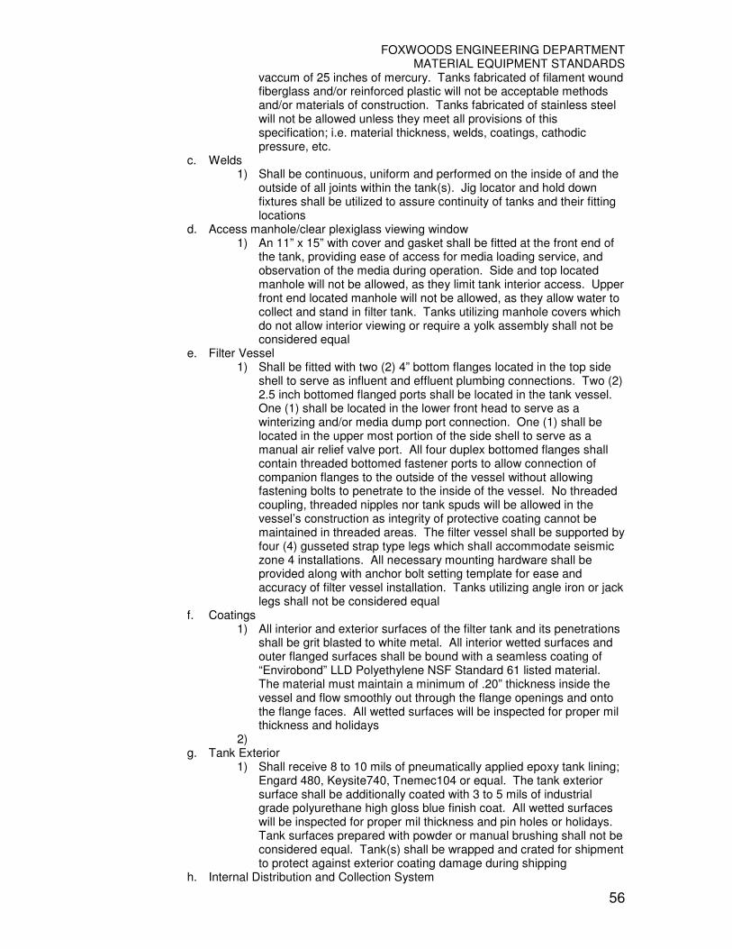
FOXWOODS ENGINEERING DEPARTMENT MATERIAL EQUIPMENT STANDARDS
56
vaccum of 25 inches of mercury. Tanks fabricated of filament wound fiberglass and/or reinforced plastic will not be acceptable methods and/or materials of construction. Tanks fabricated of stainless steel will not be allowed unless they meet all provisions of this specification; i.e. material thickness, welds, coatings, cathodic pressure, etc.
c. Welds 1) Shall be continuous, uniform and performed on the inside of and the
outside of all joints within the tank(s). Jig locator and hold down fixtures shall be utilized to assure continuity of tanks and their fitting locations
d. Access manhole/clear plexiglass viewing window 1) An 11” x 15” with cover and gasket shall be fitted at the front end of
the tank, providing ease of access for media loading service, and observation of the media during operation. Side and top located manhole will not be allowed, as they limit tank interior access. Upper front end located manhole will not be allowed, as they allow water to collect and stand in filter tank. Tanks utilizing manhole covers which do not allow interior viewing or require a yolk assembly shall not be considered equal
e. Filter Vessel 1) Shall be fitted with two (2) 4” bottom flanges located in the top side
shell to serve as influent and effluent plumbing connections. Two (2) 2.5 inch bottomed flanged ports shall be located in the tank vessel. One (1) shall be located in the lower front head to serve as a winterizing and/or media dump port connection. One (1) shall be located in the upper most portion of the side shell to serve as a manual air relief valve port. All four duplex bottomed flanges shall contain threaded bottomed fastener ports to allow connection of companion flanges to the outside of the vessel without allowing fastening bolts to penetrate to the inside of the vessel. No threaded coupling, threaded nipples nor tank spuds will be allowed in the vessel’s construction as integrity of protective coating cannot be maintained in threaded areas. The filter vessel shall be supported by four (4) gusseted strap type legs which shall accommodate seismic zone 4 installations. All necessary mounting hardware shall be provided along with anchor bolt setting template for ease and accuracy of filter vessel installation. Tanks utilizing angle iron or jack legs shall not be considered equal
f. Coatings 1) All interior and exterior surfaces of the filter tank and its penetrations
shall be grit blasted to white metal. All interior wetted surfaces and outer flanged surfaces shall be bound with a seamless coating of “Envirobond” LLD Polyethylene NSF Standard 61 listed material. The material must maintain a minimum of .20” thickness inside the vessel and flow smoothly out through the flange openings and onto the flange faces. All wetted surfaces will be inspected for proper mil thickness and holidays
2) g. Tank Exterior
1) Shall receive 8 to 10 mils of pneumatically applied epoxy tank lining; Engard 480, Keysite740, Tnemec104 or equal. The tank exterior surface shall be additionally coated with 3 to 5 mils of industrial grade polyurethane high gloss blue finish coat. All wetted surfaces will be inspected for proper mil thickness and pin holes or holidays. Tank surfaces prepared with powder or manual brushing shall not be considered equal. Tank(s) shall be wrapped and crated for shipment to protect against exterior coating damage during shipping
h. Internal Distribution and Collection System

FOXWOODS ENGINEERING DEPARTMENT MATERIAL EQUIPMENT STANDARDS
57
1) The internal components shall be hydraulically balanced to prevent migration of the filter media during the filtration cycle, and must uniformly fluidize the media in the backwash cycle without channeling or breakthrough at any one location. The influent distribution system shall consist of no less than eight (8) hydraulic distribution lenses, which shall be fabricated of ABS plastic and PVC pipe and fittings. Distribution systems consisting of slotted pipes, or splash plates, will not be considered equal. The collection system shall consist of PVC fittings, Schedule 80 piping and molded ABS “V” slotted 12” long threaded laterals. The laterals shall be capable of retaining a #30 grade filter media with a minimum head loss. Laterals which are made from plastic pipe with saw cut slots will not be allowed. Laterals which utilize slots which extend around the entire perimeter of the lateral shall not be allowed, due to uneven sand bed fluidization. A minimum of twenty (20) molded laterals shall be utilized in each filter tank, assuring an even and complete fluidization of filter media during the backwashing cycle. The combined open areas of the laterals shall not exceed a velocity of six (6) feet per second at the designed filter flow rate. All internal components, including main headers, must be removable for repair and/or replacement should damage occur
i. Air Relief System 1) An internal automatic air bleed system shall be provided in the tank.
An anti-plug protective shield screen shall be installed on each assembly. A manually operated external air relief valve shall be provided on the tank. Threaded manual air relief connections shall not be allowed
j. Winterizing and Media Dump Port 1) In the front of each vessel shall be located a ¾” or larger drain fitting
which shall allow the evacuation of all water from the tank for the purpose of winterizing or service. A ¾ or larger inch o-ring seal plug adapter shall be provided for ease of removal and replacement. No media shall be allowed to leave the tank during the draining process. The media dump port shall allow for the removal of all filter media from the vessel within 45 minutes. This dump port shall be a minimum of 2 inches in diameter and shall be installed in the front of each filter vessel, allowing for easy access. Threaded media dump port connections shall not be allowed
k. Backwash Valving and Piping
1) One (1) two-way, three port, backwash valve shall be supplied on each filter tank. The valve body shall be machined from heavy cast bronze. Plastic, cast iron, or aluminum valve bodies will not be considered for this. Industrial/Commercial use: Victaulic type couplers shall be provided at each port of the valve for connection to the filter tank and manifold piping. The couplers shall be hot dip galvanized prior to receiving a coating of an industrial grade polyurethane high gloss blue finish coat. Each valve shall be fitted with a nominal six inch diameter piston operated hydraulic cylinder to actuate the valve. Electrically or diaphragm actuated valves, or hydraulically actuated diaphragm valves will not be allowed. External valve linkage will not be allowed for safety and potential maladjustment reasons. The internal piston shaft shall be Type 302 stainless steel and shall be supported above and below the piston with Delrin guide bushings. The internal piston shaft shall incorporate two shaft supports to ensure proper alignment, valves which incorporate a single shaft support shall not be allowed. Silicon impregnated felt wiper shall be provided for internal shaft quad-ring lubrication. All wetted surfaces shall be coated in accordance with

FOXWOODS ENGINEERING DEPARTMENT MATERIAL EQUIPMENT STANDARDS
58
filter tank interior coating specification. All exterior coating of the valve shall be in accordance with the exterior coating specification of the filter tank. All stainless steel components used in this assembly shall be passivated and rinsed after forming and machining. The backwash valve shall be designed to allow for continuous circulation pump operation during the cycling between filter and backwash of the filter system. This requirement is for the prevention of potential loss of circulation pump prime and/or damage to boiler, chemical feed systems and piping. To reduce head loss through the valve(s), the valve shaft shall operate fully extended during the filter cycle, and shall retract during the backwash cycle to protect the shaft from excessive debris. The backwash cycle shall automatically restage the backwash sequence for each backwash cycle. Systems which backwash each tank in the same order each backwash cycle shall not be considered equal, as this does not ensure complete debris removal from the tanks equally and caused mud balls to develop in the sand bed. The backwash valve shall be designed to allow the operator to visually verify valve position in either filter or backwash position. Valves which do not allow for visual mode inspection shall not be considered equal.
l. Flow Control Valve 1) A rate of flow, control valve shall be provided for installation onto the
effluent line of the filter system. The valve shall be a tamper proof design, but field adjustable, assuring the proper system flow rate. The valve shall be constructed of PVC. Systems utilizing a butterfly valve for this critical control function shall not be considered equal
m. Piping and Valves 1) The influent, effluent and waste manifolds shall be constructed of
PVC Schedule 80 pipe and fittings. The waste line fitted with a waste control valve and clear sight glass assembly. The valve shall be of the tamper proof design and require a tool for backwash flow rate change.
The effluent line shall be fitted with a flow control valve, which shall be of the tamper proof design and require a tool for system flow rate change. Systems which utilize buttery valves for these two critical flow adjustments shall not be considered equal. To minimize floor space requirements and provide unhindered access to the filter control microprocessor, backwash valves, media dump port and manholes, all piping shall be located on the top of the filter tanks. All piping shall be factory assembled and pressure tested. The assemblies shall then be coated with a material to prevent ultraviolet ray degradation of the plastic which shall color match all other system components. In order to avoid excessive stress at the grooved fittings, the influent manifold shall be mounted at the top port of the backwash valve, and the waste manifold shall be mounted at the rear port of the backwash valve. All manifold piping shall be self supporting. Systems which do no incorporate self-supporting manifold piping shall not be considered equal
n. Automatic Differential Pressure PLC Filter Controller 1) The filter control console shall govern the operation of the filter
system with logic provided by a programmable logic controller (PLC)

FOXWOODS ENGINEERING DEPARTMENT MATERIAL EQUIPMENT STANDARDS
59
with a LCD screen operator interface. It shall provide direct constant read-out for modes of operation, filter flow rate, and alarm status. It shall also control hydraulic activation of backwash for up to fourteen (14) filter vessels with an electromechanical solenoid array. Printed circuit board based controllers with mechanical hydraulic multi-port valves shall not be considered equal. All components of the CPU module shall be housed within a fully gasket NEMA 4X, hinged, non-conductive, water, oil and dust tight molded plastic enclosure with external lockable closing devices. Dimensions 13.5” W x 12” H x 8” D. The operator interface screen display on the front of the enclosure shall be a wear resistant, weatherproof, backlit LCD type, with fifteen (15) different 2-line character screens with a minimum size 2.25” x .50”. The large red emergency stop push-button shall be mounted prominently on the front panel to interrupt power to the circulation pump motor contactor and all enabling circuits for backwash. The PLC controller shall control backwash for up to fourteen (14) filter vessels manually, by differential pressure, or external signal. The backwash sequence shall be alternated with operator set backwash time and intervals. A backwash counter shall log all backwash sequences and shall be re-settable. A motor rated contactor shall be provided for the hydraulic sustaining system. Water flow rate will be displayed with a signal from an external paddle wheel sensor and an operator set K-Factor. Backwash may be initiated by an operator set flow rate. The PLC controller shall have a user defined heater cool down timer (fireman switch). Controllers with preset nonadjustable switches shall not be considered equal. The backwash solenoid assembly shall consist of heavy duty Electromechanical hydraulic valves mounted on a directionally flow controlled, venting manifold. All solenoids shall have the ability to be manually operated by means of pushbutton actuators. Systems which utilize a metallic stager, plastic stager, linkage assembly or motorized valve shall not be allowed. All system setup screens able to be pass code protected. The control PLC shall provide the following features and functions
• Manual initiation of backwash (Pushbutton)
• Adjustable differential pressure backwash initiation
• Flow rate reduction backwash initiation
• Uninterrupted main circulating pump operation during backwash cycle
• Direct fired boiler cool down mode
• Terminal hook-up board and switching to control accessory equipment
• Battery backup to maintain time during power failure
• Backwash counter
• Digital direct readout flow meter in gpm or M3/hr. with flow sensor, 25 foot cable and mounting saddle
• Power input shall be 115 VAC, 60Hz/220 VAC, 50Hz The entire PLC filter controller shall be Underwriters Laboratories, Inc., listed as a filter controller under Standard 508A Industrial Controllers. Filter control consoles which are not UL listed, or which are only partially listed shall not be allowed.
o. Pressure Supply System 1) An in-line “Y” Strainer, 2-1/2 inch 0-100 PSI pressure gauge and
pressure regulator shall be supplied as part of the filter system. The pressure supply system shall clean and govern the pressure of the water used to actuate the filter system’s automatic valves
p. Gauge Panel
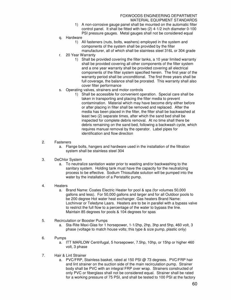
FOXWOODS ENGINEERING DEPARTMENT MATERIAL EQUIPMENT STANDARDS
60
1) A non-corrosive gauge panel shall be mounted on the automatic filter control panel. It shall be fitted with two (2) 4-1/2 inch diameter 0-100 PSI pressure gauges. Metal gauges shall not be considered equal
q. Hardware 1) All fasteners (nuts, bolts, washers) employed in the system and
components of the system shall be provided by the filter manufacturer, all of which shall be stainless steel 316L or 304 grade
r. 20 Year Warranty 1) Shall be provided covering the filter tanks, a 10 year limited warranty
shall be provided covering all other components of the filter system and a one year warranty shall be provided covering all electrical components of the filter system specified herein. The first year of the warranty period shall be unconditional. The first three years shall be full coverage, the balance shall be prorated. This warranty shall also cover filter performance
s. Operating valves, strainers and motor controls 1) Shall be accessible for convenient operation. Special care shall be
taken in transporting and placing the filter media to prevent contamination. Material which may have become dirty either before or after placing in filter shall be removed and replaced. After the media has been placed in the filter, the filter shall be backwashed at least two (2) separate times, after which the sand bed shall be inspected for complete debris removal. At no time shall there be debris remaining on the sand bed, following a backwash cycle, which requires manual removal by the operator. Label pipes for identification and flow direction
2. Fasteners a. Flange bolts, hangers and hardware used in the installation of the filtration
system shall be stainless steel 304 3. DeChlor System
a. To neutralize sanitation water prior to wasting and/or backwashing to the sanitary system. Holding tank must have the capacity for the neutralizing process to be effective. Sodium Thiosulfate solution will be pumped into the water by the installation of a Peristaltic pump.
4. Heaters
a. Brand Name: Coates Electric Heater for pool & spa (for volumes 50,000 gallons and less). For 50,000 gallons and larger and for all Outdoor pools to be 200 degree Hot water heat exchanger. Gas heaters Brand Name: Lochinvar or Teledyne Laars. Heaters are to be in parallel with a bypass valve to restrict the full flow to a percentage of the water to bypass the line. Maintain 85 degrees for pools & 104 degrees for spas
5. Recirculation or Booster Pumps
a. Sta-Rite Maxi-Glas for 1 horsepower, 1-1/2hp, 2hp, 3hp and 5hp, 460 volt, 3 phase (voltage to match house volts; this type & size pump, plastic only)
6. Pumps
a. ITT MARLOW Centrifugal, 5 horsepower, 7.5hp, 10hp, or 15hp or higher 460 volt, 3 phase
7. Hair & Lint Strainer
a. PVC/FRP, Stainless basket, rated at 150 PSI @ 73 degrees. PVC/FRP hair and lint strainer on the suction side of the main recirculation pump. Strainer body shall be PVC with an integral FRP over wrap. Strainers constructed of only PVC or fiberglass shall not be considered equal. Strainer shall be rated for a working pressure of 75 PSI, and shall be tested to 100 PSI at the factory

FOXWOODS ENGINEERING DEPARTMENT MATERIAL EQUIPMENT STANDARDS
61
8. Hair & Lint Strainer Cover
a. Shall be constructed of clear acrylic to allow visual inspection of the strainer, to eliminate unnecessary cleaning. The top of the strainer shall feature quick-disconnect top tee handles, and flanged inlet and outlet connections. Flanges shall be Van Stone loose ring for ease of installation. Strainer shall be supplied with a stainless steel basket, including one spare basket for each strainer
9. Auto Fill System
a. Fillion Associates 3-Probe type, low voltage with control Box. Mandatory for all make-up water fills. In feature ponds requiring make-up fills. In feature ponds where there are underwater lights which require minimum 2” of water above light lens (to prevent melt down of light fixtures). Pools & Spas make-up water to be tempered with Symmons Tempering Valve P/N 5-1000, 1-1/2” inlet X 2” outlet
10. Water Hammer Arrestors
a. Brand Name: Josam installed on make-up hot & cold water on all pools / spas & water features close to pump rooms
11. Chemistry Microprocessors Controllers for monitoring chemistry
a. Becs System 5 automatic pool chemistry monitor/controller for pH and chlorine residuals. Includes programmable microprocessor design, digital LCD readouts, keypad control, NEMA 4X polycarbonate enclosure, battery backup, panel mounted sample stream plumbing, flow sensor, proportional feed mode, high/low chlorine and pH alarms, overfeed limit timers, temperature readout, direct alarm readout and adjustable trip points. Also includes menu driven 40 character twelve line LCD display, data modem, start-up and operator training. “Direct Dial” modem lines. Two (2) lines each for Becsys Chemistry controllers
12. Flow Meters
a. Brand Name: Blue/White – Impact type for installations to indicate volume of flow from chlorinators. To be type “In-Line Vertical flow with straight male tail pieces”. Main recirculation system type of flow meter to be brand name: Signet Digital model #509 flow meters for main circulation system
13. Tempering Valves
a. To be installed on each separate pool and spa system. Brand Name: Symmons (only) for Make-Up water to all Pools & Spas. Installed on wall in pump room to be accessible
14. Eye Wash Stations
a. Complete assembly with basin & shower, including tempering valve
15. Under Water Lights a. Amerlites (24 voltage underwater lighting) with blue lens
16. Bio-Chemistry Test Station
a. All chemistry controllers are to be installed on same wall, on level plane b. LCD display to be at a height of 5 feet 4 inches from deck c. Water resistant counter-top installed @ 40 inches from deck under full length
of chemistry controllers d. Flow cell test valves to have ¼” brass or stainless steel ball valves with Tygon
tubing to receiver. Terminated and anchored above open receiver (in order to place sample tubes & comparators for filling).

FOXWOODS ENGINEERING DEPARTMENT MATERIAL EQUIPMENT STANDARDS
62
17. Gas Tox Monitors a. Scott Instruments, Inc., sensors and receivers for oxygen & chlorine, to be
connected & monitored by Engineering Meta-System at BMSO. Preferred vendor is Neponset Control, Inc.
b. Scott Freedom 5000 Gas Transmitter, P/N 5080-1-1-1-2, Type of gas: Oxygen, Range: 0-25% LEL, Integral sensor, wall/surface mounting
c. Scott Freedom 5000 Gas Transmitter, PN 5024-20-1-1-1-2, Type of gas: Chlorine, Range: 0-5 ppm, Integral sensor, wall/surface mounting
d. Scott QuadScan II Four Channel Receiver, P/N 7400-2-1-1, Two activated Channels, NEMA-4X enclosure, 4-20mA input, no relays
e. Edwards Signal Flashing Stackable Beacon, Two Stacks Flashing, incandescent (P/N 102LS-FIN-N5), amber and red lights (P/N 102LMA & P/N 102LMR), 120 VAC, NEMA 3R and 4X enclosure, base mounting (P/N 102TBS-N5)
18. Chlorinators
a. PPG Calcium Hypochlorite table type feeders for pools 35,000 gallons and larger
b. PPG Model 3012AT is for pools up to 75,000 gallons. It holds 8lbs of AccuTab blue tablets
c. PPG Model 3070AT is for pools up to 300,000 gallons. It holds 75lbs of AccuTab blue tablets
d. PPG Model 3140AT is for pools up to 1,000,000 gallons. It holds 150lbs of Ace-Tab Blue Tablets
19. PH & Alkalinity Control
a. Brand name: Fillion Associates, Inc. CO2 System, Dual Regulator b. Water Park Capacity CO2 system; to be Bulk tank capacity c. CO2-3A feed system with 0 – 30 SCFH flow tube and eductor kit d. CO2-6 dual tank CO2 regulator e. OSHA approved CO2 poly tank holder with strap and chain; plastic only
20. Monitoring Device
a. Brand name: Sensorphone Model 1108 remote monitoring system. Each to have “Direct Dial” type for modem communication (computer, pager access & remote programming. All pool / spa pump and chemical rooms to be monitored for Sound level, humidity levels, temperature, water leaking on deck, electrical power).
21. Butterfly Valve
a. To be brand name: ASAHI
22. Spa 10-Minute Time Delay Electrical/Pneumatic Control a. To be brand name: Len Gordons
23. Pressure Gauges
a. Brand name – “Terice” to be 5.5 inches diameter face, stainless body. Zero to sixty PSIG for positive pressure only and -30HG to 0-30 PSIG for systems requiring a compound gauge. 1/8lb increment, to have IPS brass ball valves, valve and snubbers. Gauges are to be installed on all pumps suction and discharge ports, filters influent & effluent connections
24. Flange Increasers
a. To be stainless steel/fiberglass
25. Chemical Storage Tanks stored in Pump Rooms a. Vertical bulk storage tanks to be double wall tanks or equal of 70 gallon plastic
tank inside of 100 gallon plastic tank with plastic cover, with 1/20 HP mixer or
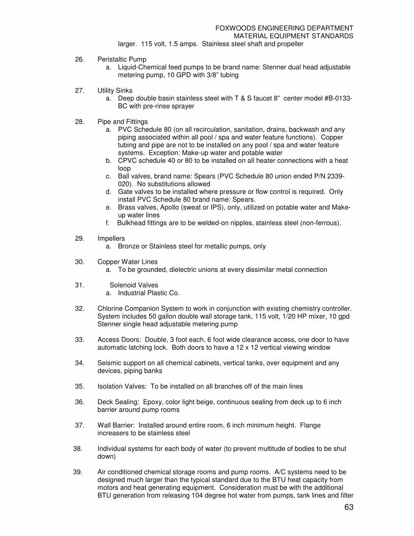
FOXWOODS ENGINEERING DEPARTMENT MATERIAL EQUIPMENT STANDARDS
63
larger. 115 volt, 1.5 amps. Stainless steel shaft and propeller
26. Peristaltic Pump a. Liquid-Chemical feed pumps to be brand name: Stenner dual head adjustable
metering pump, 10 GPD with 3/8” tubing
27. Utility Sinks a. Deep double basin stainless steel with T & S faucet 8” center model #B-0133-
BC with pre-rinse sprayer
28. Pipe and Fittings a. PVC Schedule 80 (on all recirculation, sanitation, drains, backwash and any
piping associated within all pool / spa and water feature functions). Copper tubing and pipe are not to be installed on any pool / spa and water feature systems. Exception: Make-up water and potable water
b. CPVC schedule 40 or 80 to be installed on all heater connections with a heat loop
c. Ball valves, brand name: Spears (PVC Schedule 80 union ended P/N 2339-020). No substitutions allowed
d. Gate valves to be installed where pressure or flow control is required. Only install PVC Schedule 80 brand name: Spears.
e. Brass valves, Apollo (sweat or IPS), only, utilized on potable water and Make-up water lines
f. Bulkhead fittings are to be welded-on nipples, stainless steel (non-ferrous).
29. Impellers a. Bronze or Stainless steel for metallic pumps, only
30. Copper Water Lines
a. To be grounded, dielectric unions at every dissimilar metal connection 31. Solenoid Valves
a. Industrial Plastic Co.
32. Chlorine Companion System to work in conjunction with existing chemistry controller. System includes 50 gallon double wall storage tank, 115 volt, 1/20 HP mixer, 10 gpd Stenner single head adjustable metering pump
33. Access Doors: Double, 3 foot each, 6 foot wide clearance access, one door to have
automatic latching lock. Both doors to have a 12 x 12 vertical viewing window
34. Seismic support on all chemical cabinets, vertical tanks, over equipment and any devices, piping banks
35. Isolation Valves: To be installed on all branches off of the main lines
36. Deck Sealing: Epoxy, color light beige, continuous sealing from deck up to 6 inch
barrier around pump rooms 37. Wall Barrier: Installed around entire room, 6 inch minimum height. Flange
increasers to be stainless steel
38. Individual systems for each body of water (to prevent multitude of bodies to be shut down)
39. Air conditioned chemical storage rooms and pump rooms. A/C systems need to be
designed much larger than the typical standard due to the BTU heat capacity from motors and heat generating equipment. Consideration must be with the additional BTU generation from releasing 104 degree hot water from pumps, tank lines and filter

FOXWOODS ENGINEERING DEPARTMENT MATERIAL EQUIPMENT STANDARDS
64
during regular preventative maintenance weekly drain & cleaning of all the spas or from the unit for Pool / Spa pump rooms to handle the BTU output from all equipment
40. Fresh air ventilation in and exhaust systems in all chemical pump rooms. Separate
from the house system
41. Minimum of six floor drains in each pump room. Minimum diameter floor drain
indirect waste line to be 3 inches 42. Rooms to be enclosed with two (2) hour sheet rock walls and ceiling
43. Electrical panels to be installed outside of rooms by the access door
44. GAST Commercial Blowers, for Spas
45. Chlorine Companion System (Non-Chlorine Oxidizer) to work in conjunction with the
sanitation chemistry. System includes 50 gallon double wall storage tank, 115 volt, 1/20 HP mixer, 10 gpd Stenner single head adjustable metering pump
46. Minimum of 6 inch diameter pump room sanitary waste 6” x 8” receiver for
backwashing drain, trapped and vented. Minimum of 128 GPM flow required 47. Underground pump rooms: Sump Pump, Bilco basement door with hand rails with
staircase
48. Access Doors for pump rooms to have small viewing window, non-breakable glass. Exception: Chemical rooms
49. Supply fresh air-in and exhaust
50. 2” hot and cold water to be supplied to pump rooms with Backflow Preventer Valves
51. Potable hot water recirculation return lines to be installed for all P/S & W.F. pump
rooms
52. Insulation: To be covered with plastic covers on potable copper water lines. No exposed white fiberglass in P/S & W.F. pump rooms
53. Mating fittings on tanks to be the same type of material or Dielectric fittings are to be
installed
54. Support platforms and racks to be stainless steel 304
55. All Pool / Spa Chemical rooms to be designed for the storage of corrosives, dry and liquid. 6 inch high barrier around room, with suspended ceiling tile system. A/C system, epoxy coated chemical cabinets. Fresh air-in and exhaust out isolated independent systems
56. Electrical wall receptacles to have water shielded and lockable plastic covers
57. Wall mounted phones with adjustable speaker and ringer volume control
58. Decks: Slip and water tight sealed
59. Light fixtures to be water tight, NEMA rated
60. Switches to be water tight and installed within 2 feet of pump motors, for easy access
of electrical shut off

FOXWOODS ENGINEERING DEPARTMENT MATERIAL EQUIPMENT STANDARDS
65
61. Rooms to accommodate adequate walking and access of equipment around any
electrical equipment
62. Water lines are not to be installed above or below electrical panels or switches per IC 63. Resilient mount: Pumps and Motors
64. Electrical panels: NEMA-4 rated
65. Two egress entrance/exits in each room
66. Compress air supply to each pump room
67. When sanitizers need to be disposed in a sanitary waste to MPTN WWTP, a
Dechlorination system will be installed, consisting of a double wall plastic Receiving tank large enough to handle the full backwashed water to be neutralized by the injection Sodium Thiosulfate stored in a 50 gallon double wall plastic tank with a double head Stenner Peristaltic pump and mixer with stainless shaft
68. Spill kit
69. Emergency Shut off: At entry, install button (shutting off entire room of equipment, except for illuminators, prior to entering rooms)
70. Water Features, minimum of four (4) floor drains, minimum 4 inch waste lines
a. Bromine to be utilized on Indoor Water Features only 1) Neptune Erosion Feeder model BT-15 Erosion Feeder is to be
installed and with unions at all supply/discharge connections b. Set of two (2) PVC coupon holders with hardware, and one (1) copper coupon
and one (1) mild steel coupon for coupon rack built by others 71. SR Smith Portable Aquatic Lift (PAL Series) Battery powered Pool Lift with arm
and foot rests
72. SR Smith Portable Aquatic Lift (PAL Series) Battery powered Spa Lift with Arm rests, with foot rests
C. Pool Design � 19-13-B-33b Public Pools, Swimming Pools – State of Connecticut, Department
of Public Health Code, State of Connecticut Design Guide for Pools & Spas, and International Building Codes
� NEC 2005; Article 680 Swimming Pools, Fountains and Similar Installations
1. Spa shell to be foam insulated
2. Underwater illumination to be fiber optic or equal to be low voltage fixture with
blue lens. For pools, each illuminator to be equal to 500 watts. For spas, illuminator to be equal to 300 watts
3. Pool & Spa Emergency shut off switch to be installed by all spa areas per NEC
2002 code
4. Two (2) main drain boxes, anti-vortex type grates for each Pool & Spa installed in bottom of pool. To prevent bodily entrapment (per code & industry standards). Pool main drain boxes need to be installed in the lowest point in the deep end, bottom of pool
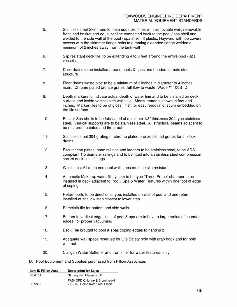
FOXWOODS ENGINEERING DEPARTMENT MATERIAL EQUIPMENT STANDARDS
66
5. Stainless steel Skimmers to have equalizer lines with removable weir, removable
front load basket and equalizer line connected back to the pool / spa shell and welded to the side wall of the pool / spa shell. If plastic, Hayward with top covers access with the skimmer flange bolts to a mating extended flange welded a minimum of 2 inches away from the tank wall
6. Slip resistant deck tile, to be extending 4 to 8 feet around the entire pool / spa
vessels
7. Deck drains to be installed around pools & spas and bonded to main steel structure
8. Floor drains waste pipe to be a minimum of 3 inches in diameter to 4 inches
main. Chrome plated bronze grates, full flow to waste, Wade #1100STD
9. Depth markers to indicate actual depth of water line and to be installed on deck surface and inside vertical side walls tile. Measurements shown in feet and inches. Marker tiles to be of gloss finish for easy removal of scum embedded on the tile surface
10. Pool or Spa shells to be fabricated of minimum 1/8” thickness 304 type stainless
steel. Vertical supports are to be stainless steel. All structural beams adjacent to be rust proof painted and fire proof
11. Stainless steel 304 grating or chrome plated bronze slotted grates for all deck
drains
12. Escutcheon plates, hand railings and ladders to be stainless steel, to be ADA compliant 1.5 diameter railings and to be fitted into a stainless steel compression socket deck flush fittings
13. Wall steps: All deep end pool wall steps must be slip resistant
14. Automatic Make-up water fill system to be type “Three Probe” chamber to be
installed in deck adjacent to Pool / Spa & Water Features within one foot of edge of coping
15. Return ports to be directional type, installed on wall of pool and one return
installed at shallow step closest to lower step
16. Porcelain tile for bottom and side walls
17. Bottom to vertical edge lines of pool & spa are to have a large radius of chamfer edges, for proper vacuuming
18. Deck Tile brought to pool & spas coping edges to hand grip
19. Adequate wall space reserved for Life Safety pole with grab hook and for pole
with net 20. Culligan Water Softener and Iron Filter for water features, only
D. Pool Equipment and Supplies purchased from Fillion Associates
Item ID Fillion Asso. Description for Sales
00-6101 Stirring Bar, Magnetic, 1"
00-9058 FAS- DPD Chlorine & Bromine/pH 7.0 - 8.0 Comparator Test Block
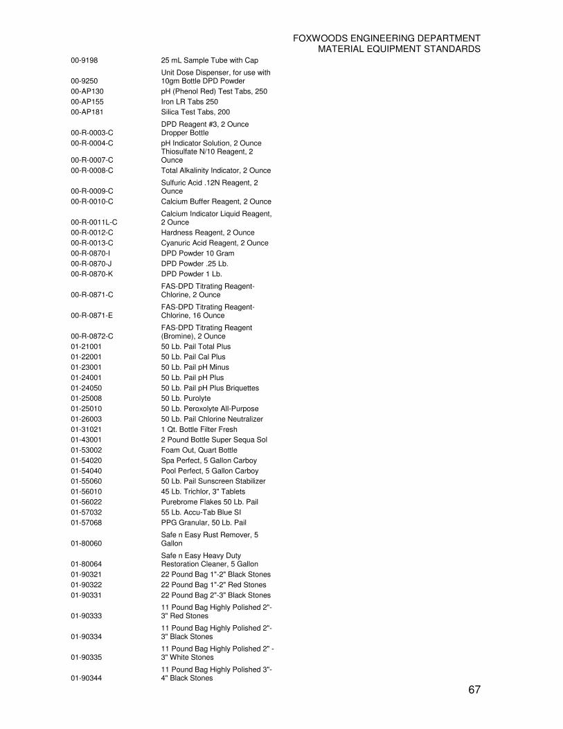
FOXWOODS ENGINEERING DEPARTMENT MATERIAL EQUIPMENT STANDARDS
67
00-9198 25 mL Sample Tube with Cap
00-9250 Unit Dose Dispenser, for use with 10gm Bottle DPD Powder
00-AP130 pH (Phenol Red) Test Tabs, 250
00-AP155 Iron LR Tabs 250
00-AP181 Silica Test Tabs, 200
00-R-0003-C DPD Reagent #3, 2 Ounce Dropper Bottle
00-R-0004-C pH Indicator Solution, 2 Ounce
00-R-0007-C Thiosulfate N/10 Reagent, 2 Ounce
00-R-0008-C Total Alkalinity Indicator, 2 Ounce
00-R-0009-C Sulfuric Acid .12N Reagent, 2 Ounce
00-R-0010-C Calcium Buffer Reagent, 2 Ounce
00-R-0011L-C Calcium Indicator Liquid Reagent, 2 Ounce
00-R-0012-C Hardness Reagent, 2 Ounce
00-R-0013-C Cyanuric Acid Reagent, 2 Ounce
00-R-0870-I DPD Powder 10 Gram
00-R-0870-J DPD Powder .25 Lb.
00-R-0870-K DPD Powder 1 Lb.
00-R-0871-C FAS-DPD Titrating Reagent-Chlorine, 2 Ounce
00-R-0871-E FAS-DPD Titrating Reagent-Chlorine, 16 Ounce
00-R-0872-C FAS-DPD Titrating Reagent (Bromine), 2 Ounce
01-21001 50 Lb. Pail Total Plus
01-22001 50 Lb. Pail Cal Plus
01-23001 50 Lb. Pail pH Minus
01-24001 50 Lb. Pail pH Plus
01-24050 50 Lb. Pail pH Plus Briquettes
01-25008 50 Lb. Purolyte
01-25010 50 Lb. Peroxolyte All-Purpose
01-26003 50 Lb. Pail Chlorine Neutralizer
01-31021 1 Qt. Bottle Filter Fresh
01-43001 2 Pound Bottle Super Sequa Sol
01-53002 Foam Out, Quart Bottle
01-54020 Spa Perfect, 5 Gallon Carboy
01-54040 Pool Perfect, 5 Gallon Carboy
01-55060 50 Lb. Pail Sunscreen Stabilizer
01-56010 45 Lb. Trichlor, 3" Tablets
01-56022 Purebrome Flakes 50 Lb. Pail
01-57032 55 Lb. Accu-Tab Blue SI
01-57068 PPG Granular, 50 Lb. Pail
01-80060 Safe n Easy Rust Remover, 5 Gallon
01-80064 Safe n Easy Heavy Duty Restoration Cleaner, 5 Gallon
01-90321 22 Pound Bag 1"-2" Black Stones
01-90322 22 Pound Bag 1"-2" Red Stones
01-90331 22 Pound Bag 2"-3" Black Stones
01-90333 11 Pound Bag Highly Polished 2"-3" Red Stones
01-90334 11 Pound Bag Highly Polished 2"-3" Black Stones
01-90335 11 Pound Bag Highly Polished 2" - 3" White Stones
01-90344 11 Pound Bag Highly Polished 3"-4" Black Stones
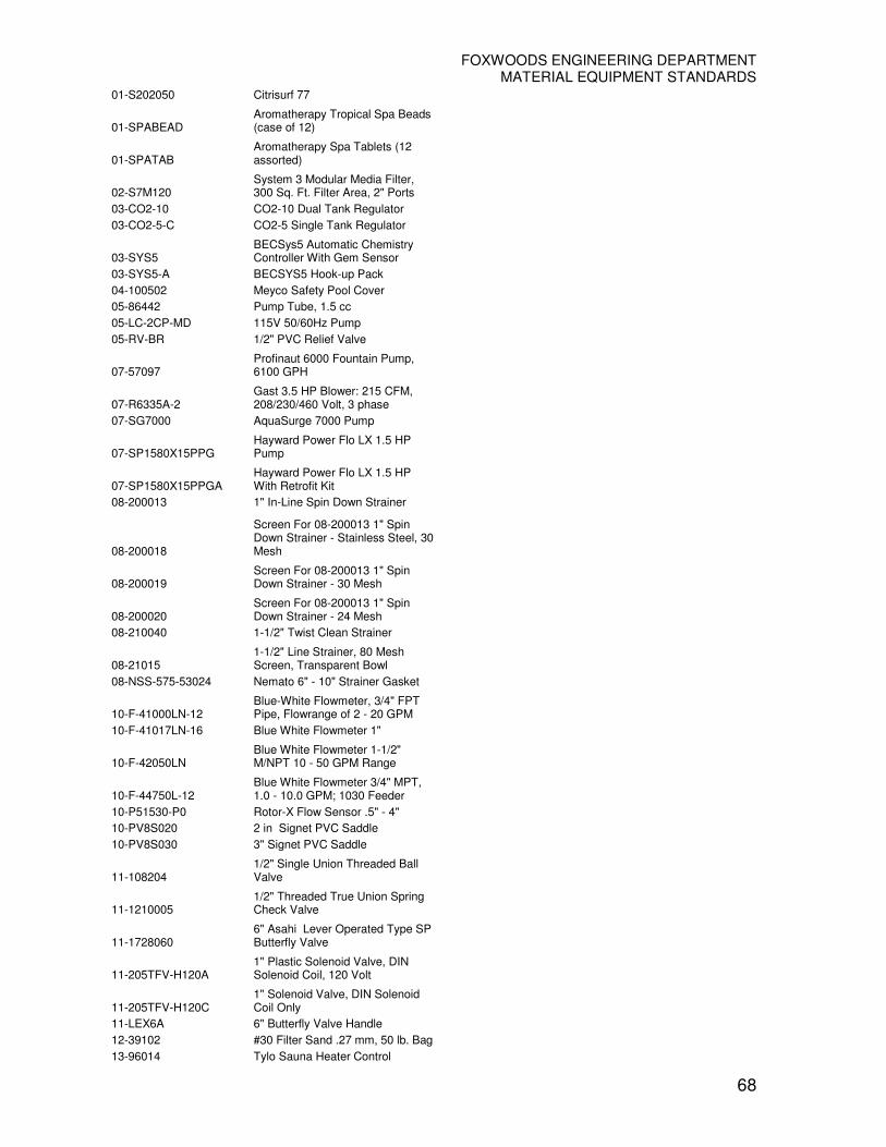
FOXWOODS ENGINEERING DEPARTMENT MATERIAL EQUIPMENT STANDARDS
68
01-S202050 Citrisurf 77
01-SPABEAD Aromatherapy Tropical Spa Beads (case of 12)
01-SPATAB Aromatherapy Spa Tablets (12 assorted)
02-S7M120 System 3 Modular Media Filter, 300 Sq. Ft. Filter Area, 2" Ports
03-CO2-10 CO2-10 Dual Tank Regulator
03-CO2-5-C CO2-5 Single Tank Regulator
03-SYS5 BECSys5 Automatic Chemistry Controller With Gem Sensor
03-SYS5-A BECSYS5 Hook-up Pack
04-100502 Meyco Safety Pool Cover
05-86442 Pump Tube, 1.5 cc
05-LC-2CP-MD 115V 50/60Hz Pump
05-RV-BR 1/2" PVC Relief Valve
07-57097 Profinaut 6000 Fountain Pump, 6100 GPH
07-R6335A-2 Gast 3.5 HP Blower: 215 CFM, 208/230/460 Volt, 3 phase
07-SG7000 AquaSurge 7000 Pump
07-SP1580X15PPG Hayward Power Flo LX 1.5 HP Pump
07-SP1580X15PPGA Hayward Power Flo LX 1.5 HP With Retrofit Kit
08-200013 1" In-Line Spin Down Strainer
08-200018
Screen For 08-200013 1" Spin Down Strainer - Stainless Steel, 30 Mesh
08-200019 Screen For 08-200013 1" Spin Down Strainer - 30 Mesh
08-200020 Screen For 08-200013 1" Spin Down Strainer - 24 Mesh
08-210040 1-1/2" Twist Clean Strainer
08-21015 1-1/2" Line Strainer, 80 Mesh Screen, Transparent Bowl
08-NSS-575-53024 Nemato 6" - 10" Strainer Gasket
10-F-41000LN-12 Blue-White Flowmeter, 3/4" FPT Pipe, Flowrange of 2 - 20 GPM
10-F-41017LN-16 Blue White Flowmeter 1"
10-F-42050LN Blue White Flowmeter 1-1/2" M/NPT 10 - 50 GPM Range
10-F-44750L-12 Blue White Flowmeter 3/4" MPT, 1.0 - 10.0 GPM; 1030 Feeder
10-P51530-P0 Rotor-X Flow Sensor .5" - 4"
10-PV8S020 2 in Signet PVC Saddle
10-PV8S030 3" Signet PVC Saddle
11-108204 1/2" Single Union Threaded Ball Valve
11-1210005 1/2" Threaded True Union Spring Check Valve
11-1728060 6" Asahi Lever Operated Type SP Butterfly Valve
11-205TFV-H120A 1" Plastic Solenoid Valve, DIN Solenoid Coil, 120 Volt
11-205TFV-H120C 1" Solenoid Valve, DIN Solenoid Coil Only
11-LEX6A 6" Butterfly Valve Handle
12-39102 #30 Filter Sand .27 mm, 50 lb. Bag
13-96014 Tylo Sauna Heater Control

FOXWOODS ENGINEERING DEPARTMENT MATERIAL EQUIPMENT STANDARDS
69
13-CH20006003 Coates 12 KW, 208 V Heater Element
13-CH20006004 Coates 15 KW, 208 V Heater Element
13-CH20006015 Coates 12 KW, 480 V Heater Element
13-CH20006016 Coates 15 KW, 480 V Heater Element
13-CH20006049 Coates 9 KW, 480 V Heater Element
13-CH21000900 Coates CR5 Contactor
13-CH21001200 Coates CR6 Contactor
13-CH22002001 Coates Temperature Control
13-CH22003820 Coates Temperature Limit Switch
13-CH22010752 Coates Transformer
13-CH23000102 Coates Flow Switch
13-CH23001520 Coates Pilot Switch
13-CH29018910 Coates Fuse, 60 Amp
13-CH29019525 Coates Fuse, 2 Amp
13-CH29025570 Coates Terminal Block, 2 Point
13-CH29034620 Coates Pilot Light
13-CH29034648 Coates Pilot Light Amber
13-CH44000250 Coates Gasket 4 Bolt Rubber
13-LG125N Jandy LG125N Natural Gas Heater
13-LRZ400EN Laars Jandy 399K BTU Heater
13-PRS2013 Pressure Switch
13-PRS3428 EnergyRite Air Switch (Replaces PRS2428)
13-RLY2402 Ignition Module
13-WTR2080 Lochinvar Flow Switch
14-102000
Air Button, #15 Classic Touch, Bone Beige, Complete Assembly, Len Gordon
14-113010 Control, AS-TD Combo 95 with 10 minute Delay, Len Gordon
14-131000 Lubricant, Silicone, 1 Oz. Tube (Jack's Lube)
14-131000 Lubricant, Silicone, 1 Oz. Tube (Jack's Lube)
14-134010 Ladder Anode (Pair)
14-134020 Light Anode
15-C610020 6 X 6 Depth Marker Tile "2FT", Smooth Waterline
15-C610030 6 X 6 Depth Marker Tile "3FT", Smooth Waterline
15-C610040 6 X 6 Depth Marker Tile "4FT", Smooth Waterline
15-C610507 6 X 6 Depth Marker Tile "7IN", Smooth, Waterline
15-C610508 6 X 6 Depth Marker Tile "8 IN", Smooth Waterline
15-C611500 6 X 6 Depth Marker "NO DIVING", Int'l Symbol, Smooth Waterline
15-C620020 6 X 6 Depth Marker Tile "2FT", Skid Resistant
15-C620030 6 X 6 Depth Marker Tile "3FT", Skid Resistant
15-C620040 6 X 6 Depth Marker Tile "4FT", Skid Resistant

FOXWOODS ENGINEERING DEPARTMENT MATERIAL EQUIPMENT STANDARDS
70
15-C620507 6 X 6 Depth Marker Tile "7IN", Skid Resistant, Deck Mounted
15-C620508 6 X 6 Depth Marker Tile "8 IN", Skid Resistant, Deck Mounted
15-C621500 6 X 6 Depth Marker "NO DIVING", Int'l Symbol, Skid Resistant
16-10570 Resort 30 Hammer Head Commercial Vacuum
16-10590 Marine Battery, Deep Cycle 12V
16-10592 Gel Battery Charger
16-APS2038BL Side Plate Assembly
16-HA550E Harmsco Rim Gasket, 11" EPDM
16-HH1035BK 30" Vacuum Back Head Half, Pole Side
16-HH1155 Small Drag Wheel With Bushing And Hardware
16-HH1508C Hammerhead Superfine Bag Complete With Cleat
17-10364 Stainless Steel Pole Hook Pair
17-10400 Commercial Aluminum 14" x 15" Leaf Skimmer
17-10402 Commercial Aluminum 20" x 6" Leaf Rake, Fiberglass Bag
17-10624 4' x 8' Aluminum Telescoping Pole With E-Z Lock Cam
17-10630 16' Fiberglass Pole
17-10636 11' x 22' Fiberglass Telescoping Pole
17-10640 6' x 12' Fiberglass Telescoping Pole
17-10652 Pole Connector With Hardware
17-106591 Handle Replacement, Swimline 8910 Vacuum
17-10660 Double Aluminum Hanger Set
17-10663 Double Hose, Pole, Accessory Hanger Set, Plastic
17-10666 Delrin Spring Clip
17-52039 Drum Pump
17-CCMLINX50 Poles, Towels, Life Rings Hanger
18-28303 Stainless Steel Escutcheon Plate, 1.5"
18-512379-03 Bronze Wedge Assembly
19-1200409 BECSys5 CPU/Relay PCB
19-1200411 BECSys5 UI Interface Board
19-1200459 BECSys Modem PCB
19-1210115 Level Float Switch Kit
19-1210137 Flowcell Assembly Complete With Acrylic Cover, O-Ring And Screws
19-7820009 Rotary Flowswitch, System 3-4-5 (4' Cable)
20-1104-1036 Zinc Rod Anode
20-1116-1226 12" Lateral Assembly
20-1126-1044 Valve Rebuild Kit
20-308-1050 4" Grooved Pipe Seal
20-310-1019 Felt Wiper
20-340-1421 Distributor Lens/Diffuser
20-344-1100 Internal Retainer Inboard Assy
20-344-1101 External Retainer
20-348-1040 Cup Seal 5-7/8 - 1" Centerhole
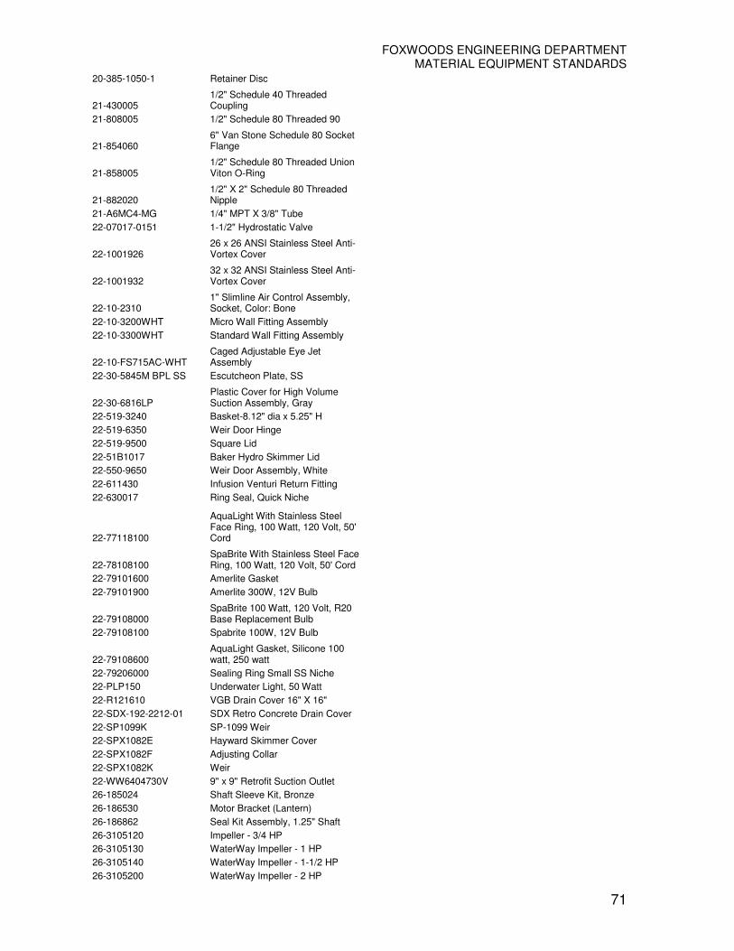
FOXWOODS ENGINEERING DEPARTMENT MATERIAL EQUIPMENT STANDARDS
71
20-385-1050-1 Retainer Disc
21-430005 1/2" Schedule 40 Threaded Coupling
21-808005 1/2" Schedule 80 Threaded 90
21-854060 6" Van Stone Schedule 80 Socket Flange
21-858005 1/2" Schedule 80 Threaded Union Viton O-Ring
21-882020 1/2" X 2" Schedule 80 Threaded Nipple
21-A6MC4-MG 1/4" MPT X 3/8" Tube
22-07017-0151 1-1/2" Hydrostatic Valve
22-1001926 26 x 26 ANSI Stainless Steel Anti-Vortex Cover
22-1001932 32 x 32 ANSI Stainless Steel Anti-Vortex Cover
22-10-2310 1" Slimline Air Control Assembly, Socket, Color: Bone
22-10-3200WHT Micro Wall Fitting Assembly
22-10-3300WHT Standard Wall Fitting Assembly
22-10-FS715AC-WHT Caged Adjustable Eye Jet Assembly
22-30-5845M BPL SS Escutcheon Plate, SS
22-30-6816LP Plastic Cover for High Volume Suction Assembly, Gray
22-519-3240 Basket-8.12" dia x 5.25" H
22-519-6350 Weir Door Hinge
22-519-9500 Square Lid
22-51B1017 Baker Hydro Skimmer Lid
22-550-9650 Weir Door Assembly, White
22-611430 Infusion Venturi Return Fitting
22-630017 Ring Seal, Quick Niche
22-77118100
AquaLight With Stainless Steel Face Ring, 100 Watt, 120 Volt, 50' Cord
22-78108100 SpaBrite With Stainless Steel Face Ring, 100 Watt, 120 Volt, 50' Cord
22-79101600 Amerlite Gasket
22-79101900 Amerlite 300W, 12V Bulb
22-79108000 SpaBrite 100 Watt, 120 Volt, R20 Base Replacement Bulb
22-79108100 Spabrite 100W, 12V Bulb
22-79108600 AquaLight Gasket, Silicone 100 watt, 250 watt
22-79206000 Sealing Ring Small SS Niche
22-PLP150 Underwater Light, 50 Watt
22-R121610 VGB Drain Cover 16" X 16"
22-SDX-192-2212-01 SDX Retro Concrete Drain Cover
22-SP1099K SP-1099 Weir
22-SPX1082E Hayward Skimmer Cover
22-SPX1082F Adjusting Collar
22-SPX1082K Weir
22-WW6404730V 9" x 9" Retrofit Suction Outlet
26-185024 Shaft Sleeve Kit, Bronze
26-186530 Motor Bracket (Lantern)
26-186862 Seal Kit Assembly, 1.25" Shaft
26-3105120 Impeller - 3/4 HP
26-3105130 WaterWay Impeller - 1 HP
26-3105140 WaterWay Impeller - 1-1/2 HP
26-3105200 WaterWay Impeller - 2 HP

FOXWOODS ENGINEERING DEPARTMENT MATERIAL EQUIPMENT STANDARDS
72
26-3111110 Volute Faceplate
26-3131400 Slinger
26-3151120 WaterWay Pump Volute
26-3193100B Pump Seal Set
26-354545 Challenger Seal, 5/8" Mechanical
26-355004 Challenger Pump Seal Plate, New style
26-355030 O-Ring, Diffuser
26-35505-1438 JS Series O-Ring
26-355086 Impeller Assembly 1/2F, 2A
26-355300 Strainer Pot
26-355301 Challenger Lid, Strainer Pot
26-355302 Challenger Pump Housing
26-355303 Plate Seal Black
26-355315 Challenger Impeller, 3/4F, 1A
26-355317 Challenger Mounting Plate
26-355329 Challenger O-Ring Front Housing
26-355330 Strainer, O-Ring
26-355398S Challenger Motor 3HP 460V 3 Phase
26-355468 Housing, Front, Black
26-355544 Challenger Impeller Assembly, 3HP
26-355545 Challenger Diffuser
26-355604 Impeller Assembly, 2-2.5 HP
26-37337-6080 Screw
26-37400-0027S JS Series Seal Assembly
26-37400-0028S Shaft Seal
26-46620000000R Check Valve For 6E4PEL Pump
26-7151201 3/8" Plug Air Relief
26-8050112 O-Ring
26-8191110 WaterWay Faceplate Volute Screw
26-AP100GH 2 HP Motor 208-230/460V, 3 Phase
26-AP100HL 3 HP Motor, 200/230/460 V, 3 Phase
26-C105-238PEBA Impeller for P4R62G3-189 Dura-Glas II Pump
26-C105-238PLA Impeller 4.85" OD 3PH
26-C1-271P Diffuser
26-C176-59P Trap Body
26-C203-194P Seal Plate Kit, Includes Plate, O-Ring, Shaft Seal
26-C3-185P Trap Cover
26-P2000533 Marlow 2-1/2-9SC Impeller
26-P48690 Volute Gasket
26-U9-226 Max-E-Glas /Dura-Glas Diffuser O-Ring
26-U9-228A Housing O-Ring
26-U9-374 Diffuser O-Ring
26-U9-375 Trap O-Ring
29-17571 Anthony Apollo Collection Elbow 2"
29-192185 5/16" X 33-1/2" Rod, NSP-60
29-24850-0008 Sta-Rite Filter O-Ring Gasket
29-24850-0009 Sta-Rite Filter O-Ring Gasket
29-24850-0102S S7M120 Lower Tank Body
29-24850-0105 Valve and Gauge Assembly
29-24851-9000 Upper Tank Half Kit, 21" Filter
29-24900-0504 Sta-Rite Adapter Bushing
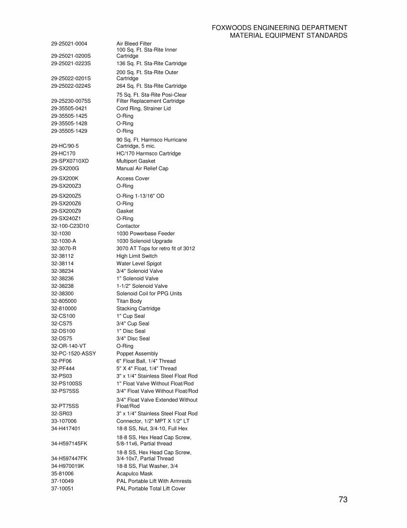
FOXWOODS ENGINEERING DEPARTMENT MATERIAL EQUIPMENT STANDARDS
73
29-25021-0004 Air Bleed Filter
29-25021-0200S 100 Sq. Ft. Sta-Rite Inner Cartridge
29-25021-0223S 136 Sq. Ft. Sta-Rite Cartridge
29-25022-0201S 200 Sq. Ft. Sta-Rite Outer Cartridge
29-25022-0224S 264 Sq. Ft. Sta-Rite Cartridge
29-25230-0075S 75 Sq. Ft. Sta-Rite Posi-Clear Filter Replacement Cartridge
29-35505-0421 Cord Ring, Strainer Lid
29-35505-1425 O-Ring
29-35505-1428 O-Ring
29-35505-1429 O-Ring
29-HC/90-5 90 Sq. Ft. Harmsco Hurricane Cartridge, 5 mic.
29-HC170 HC/170 Harmsco Cartridge
29-SPX0710XD Multiport Gasket
29-SX200G Manual Air Relief Cap
29-SX200K Access Cover
29-SX200Z3 O-Ring
29-SX200Z5 O-Ring 1-13/16" OD
29-SX200Z6 O-Ring
29-SX200Z9 Gasket
29-SX240Z1 O-Ring
32-100-C23D10 Contactor
32-1030 1030 Powerbase Feeder
32-1030-A 1030 Solenoid Upgrade
32-3070-R 3070 AT Tops for retro fit of 3012
32-38112 High Limit Switch
32-38114 Water Level Spigot
32-38234 3/4" Solenoid Valve
32-38236 1" Solenoid Valve
32-38238 1-1/2" Solenoid Valve
32-38300 Solenoid Coil for PPG Units
32-805000 Titan Body
32-810000 Stacking Cartridge
32-CS100 1" Cup Seal
32-CS75 3/4" Cup Seal
32-DS100 1" Disc Seal
32-DS75 3/4" Disc Seal
32-OR-140-VT O-Ring
32-PC-1520-ASSY Poppet Assembly
32-PF06 6" Float Ball, 1/4" Thread
32-PF444 5" X 4" Float, 1/4" Thread
32-PS03 3" x 1/4" Stainless Steel Float Rod
32-PS100SS 1" Float Valve Without Float/Rod
32-PS75SS 3/4" Float Valve Without Float/Rod
32-PT75SS 3/4" Float Valve Extended Without Float/Rod
32-SR03 3" x 1/4" Stainless Steel Float Rod
33-107006 Connector, 1/2" MPT X 1/2" LT
34-H417401 18-8 SS, Nut, 3/4-10, Full Hex
34-H597145FK 18-8 SS, Hex Head Cap Screw, 5/8-11x6, Partial thread
34-H597447FK 18-8 SS, Hex Head Cap Screw, 3/4-10x7, Partial Thread
34-H970019K 18-8 SS, Flat Washer, 3/4
35-81006 Acapulco Mask
37-10049 PAL Portable Lift With Armrests
37-10051 PAL Portable Total Lift Cover

FOXWOODS ENGINEERING DEPARTMENT MATERIAL EQUIPMENT STANDARDS
74
37-10053 Splash/Pal Lift Battery
37-10055 Splash/PAL Battery Charger, New Style
37-10056 Splash/PAL Control Unit Assembly
37-10057 PAL Footrest With Hardware
37-10058 PAL Gear Assembly
38-812972 20 Watt UV Lamp
38-812982 20 Watt UV Sleeve
E. Water Features (WF) exterior areas
1. Wet areas on faux rock to be epoxy painted to prevent paint wear from sanitizer
2. Any structural steel to be coated, fire protected and wrapped with plastic cover
3. All electrical equipment and stands to be bonded
4. Bromine to be utilized on Indoor Water Features only
5. Main drain boxes with anti-vortex grates
6. Anti-Vortex main drains
7. Corrosive material in wet areas
8. Safety-Tie Off system on all areas of height for access
9. Directional Returns Port fittings installed in areas of surface tension issues
10. Make-Up Water controlled by the installation of a “Three Probe” fill chamber &
controller
11. Water level indication sensor connected to the Show Control to prevent underwater lights burning out & melting. Alarm to be connected to Metasys
12. Remote Controller to operate the Show Control remotely for our P.M. program

FOXWOODS ENGINEERING DEPARTMENT MATERIAL EQUIPMENT STANDARDS
75
SECTION 7 – FIBEROPTIC EQUIPMENT 7.1 DESIGN STANDARDS A. Submit Fiber-Optic lighting installations to the Lead Fiber-Optic Technician to review with
Engineering Management B. The Engineering Department strongly recommends the vendors, Fiber Stars, Inc., and
Supervision International, due to their reliability and optimum performance levels for both equipment and service.
C. Illuminators are placed in areas that can be accessible to maintenance mechanics with ample
working space to repair or remove unit, when necessary. D. When installing more than one unit or a group of units in the same location, units are mounted
with a minimum distance of two feet between the units E. Units are not installed in areas where excessive dust is present
F. Cut through hold for fiber tubing one size larger and seal with appropriate sealant (fire stop, etc.)
G. Install units with cord capped ends and supply appropriate receptacles for units to be plugged in
H. When installing units either vertically or horizontally, use the appropriate mounting bars
(vertically) or install on a stable and secured horizontal surface I. Allow three to five extra feet of fiber-optic cable at the end of the run at the illuminator for a
service loop J. Follow manufacturer’s specifications for installation of port assemblies into illuminators
K. Supply manufacturer’s specification cut-sheets (model/part numbers, lamp type etc.) to the Lead
Fiber-Optic Technician, once the unit is installed L. Clearly label and mark all conduit/receptacles with panel and breaker numbers from where they
originate