fourier‐based registration for robust forward‐looking...
TRANSCRIPT

Fourier-based Registration for Robust Forward-lookingSonar Mosaicing in Low-visibility UnderwaterEnvironments
• • • • • • • • • • • • • • • • • • • • • • • • • • • • • • • • • • • •
Natalia HurtosComputer Vision and Robotics Group, University of Girona, Girona 17071, Spaine-mail: [email protected] RibasComputer Vision and Robotics Group, University of Girona, Girona 17071, Spaine-mail: [email protected] CufıComputer Vision and Robotics Group, University of Girona, Girona 17071, Spaine-mail: [email protected] PetillotOcean Systems Laboratory, Heriot-Watt University, EH14 4AS Edinburgh, United Kingdome-mail: [email protected] SalviComputer Vision and Robotics Group, University of Girona, Girona 17071, Spaine-mail: [email protected]
Received 31 December 2013; accepted 13 February 2014
Vehicle operations in underwater environments are often compromised by poor visibility conditions. For in-stance, the perception range of optical devices is heavily constrained in turbid waters, thus complicatingnavigation and mapping tasks in environments such as harbors, bays, or rivers. A new generation of high-definition forward-looking sonars providing acoustic imagery at high frame rates has recently emerged as apromising alternative for working under these challenging conditions. However, the characteristics of the sonardata introduce difficulties in image registration, a key step in mosaicing and motion estimation applications. Inthis work, we propose the use of a Fourier-based registration technique capable of handling the low resolution,noise, and artifacts associated with sonar image formation. When compared to a state-of-the art region-basedtechnique, our approach shows superior performance in the alignment of both consecutive and nonconsecutiveviews as well as higher robustness in featureless environments. The method is used to compute pose constraintsbetween sonar frames that, integrated inside a global alignment framework, enable the rendering of consis-tent acoustic mosaics with high detail and increased resolution. An extensive experimental section is reportedshowing results in relevant field applications, such as ship hull inspection and harbor mapping. C© 2014 WileyPeriodicals, Inc.
1. INTRODUCTION
Over the past few years, underwater vehicles have greatlyimproved as a tool for undersea exploration. In partic-ular, autonomous navigation, localization, and mappingthrough optical imaging have become topics of interest forresearchers in both underwater robotics and marine sci-ence communities. Underwater imagery has been used toconstruct image photomosaics with applications in harborsecurity (Negahdaripour & Firoozfam, 2006), environmen-tal monitoring (Elibol et al., 2011), and damage assessment(Lirman et al., 2010), being a key tool to locate areas or ob-
jects of interest, detect changes, or plan subsequent missionsin an area. Likewise, underwater navigation has benefitedfrom visual processing methods such as visual odometryand visual simultaneous localization and mapping (SLAM)(Eustice, Pizarro, & Singh, 2008; Gracias, Van Der Zwaan,Bernardino, & Santos-Victor, 2003) to provide drift-free nav-igation using onboard cameras.
However, a significant number of surveying and map-ping tasks in underwater scenarios are carried out in turbidwaters and murky environments where vehicles equippedonly with optical systems (i.e., cameras or lasers) are con-strained by their limited visibility range. Knowing the
Journal of Field Robotics 32(1), 123–151 (2015) C© 2014 Wiley Periodicals, Inc.View this article online at wileyonlinelibrary.com • DOI: 10.1002/rob.21516

124 • Journal of Field Robotics—2015
limitations of optical devices, underwater operations havelong relied on sonar technology for obstacle avoidance,navigation, localization, and mapping (Fairfield, Jonak,Kantor, & Wettergreen, 2007; Kinsey, Eustice, & Whitcomb,2006; Leonard, Bennett, Smith, & Feder, 1998; Roman &Singh, 2005; Tena, Reed, Petillot, Bell, & Lane, 2003) byemploying different types of sonar (e.g., profiling sonar,multibeam echosounders, scanning imaging sonar, side-scan sonar). Recently, a new generation of sonars, namelythe two-dimensional forward-looking sonars (2D FLS), haveemerged as a strong alternative for those environmentswith reduced visibility given their capabilities of deliveringhigh-definition acoustic images at a near-video frame rate(BlueView Technologies Inc., 2013; Soundmetrics Corp.,2013; Tritech Gemini, 2013).
Several researchers have drawn attention to the useof these high-frequency sonars either as a substitute oras a complementary device for optical cameras (Negah-daripour, Sekkati, & Pirsiavash, 2009). FLS imagery hasbeen employed in benthic habitat mapping (Negahdaripouret al., 2011), monitoring of fish populations (Baumgart-ner & Wales, 2006), detection of targets on the seafloor(Galceran, Djapic, Carreras, & Williams, 2012), and inspec-tion of ship hulls (Hover et al., 2012). The integration of FLSin a visual SLAM framework to constrain the navigationdrift of autonomous underwater vehicles (AUVs) has alsobeen a topic of interest (Johannsson, Kaess, Englot, Hover,& Leonard, 2010; Walter, 2008).
The processing of FLS data when performing mostof these tasks requires addressing a previous and funda-mental step, namely the registration of the sonar images.Although registration is a broadly studied field in othermodalities, notably the optical one (Zitova & Flusser, 2003),it is still a premature field with regard to sonar data. Theparticularities of FLS imagery, such as low resolution, lowsignal-to-noise ratio (SNR), and intensity alterations due toviewpoint changes, pose serious challenges to the feature-based registration techniques that have proved very effec-tive at aligning optical images.
The need to find a registration technique suited toFLS images has led researchers to investigate the prob-lem through different approaches. Most of the existingwork adopts a feature-based pipeline where feature detec-tion is performed either by using detectors at pixel scale(Kim, Intrator, & Neretti, 2004; Negahdaripour, Firoozfam,& Sabzmeydani, 2005) or by looking for more stable fea-tures extracted at region level (Aykin & Negahdaripour,2012; Johannsson et al., 2010). Leaving aside the ability ofthese methods to cope with the noise and artifacts in sonarimages, it is clear that they require the presence of promi-nent features in the environment that can be unequivocallymatched. In general, the fewer the features, the lower thepossibility of establishing successful registrations, thus im-pacting the effectiveness of subsequent processing. More-over, the difficulties in accurately extracting and matching
stable features are exacerbated when dealing with spatiallyor temporally distant sonar images found in loop closuresituations. This is a key issue since the registration of re-visited locations is crucial to bound the error accumulatedover time and achieve global consistency in mosaicing ormotion estimation applications.
In this work, we propose using a Fourier-based tech-nique to perform 2D FLS registration (Hurtos, Cufi, Petillot,& Salvi, 2012). Instead of making use of sparse feature in-formation, we propose to use a global method that takesinto account the whole image content, thus contributingto the minimization of ambiguities in the registration. Themethod is, by design, robust to noise and inhomogeneousinsonification, and it handles well the challenging nature ofsonar images, achieving a high degree of success in regis-tering not only consecutive frames but also revisited framesin loop closure situations. Without requiring the extractionof explicit features, the method is independent of the typeand number of features present in the environment and canbe robustly applied to a wide variety of applications rang-ing from surveying natural terrain to inspecting manmadescenarios.
Our purpose is to exploit this registration methodologyas a robust way to map underwater environments underlow-visibility conditions by using autonomous or remotelyoperated vehicles (ROVs). Our first focus is the genera-tion of 2D acoustic mosaics of underwater areas of interest.Possibly due to the recent introduction of high-resolutionFLS devices, the specific problem of FLS mosaicing hasonly been tackled by a few researchers (Kim et al., 2005;Negahdaripour et al., 2005, 2011) together with some re-lated work dealing specifically with FLS image registra-tion (Aykin & Negahdaripour, 2012; Johannsson et al.,2010). Nevertheless, the existing mosaicing approacheshave shown very limited results in terms of scale and com-plexity, as most of the reported mosaics are restricted toonly a few frames gathered in a single straight tracklinewhile imaging feature-rich scenarios. Here we propose acomplete mosaicing pipeline that enables the creation ofconsistent mosaics extending along various vehicle track-lines undergoing both translational and rotational 2D mo-tions, and applicable in a wide variety of environments,including those with a scarcity of features.
Toward that end, we utilize the proposed registrationtechnique to compute pairwise constraints between sonarframes that are later embedded in a pose-based graph for-mulation to enforce global alignment. This enables the ren-dering of consistent 2D acoustic mosaics of high detail thatnot only offer a global overview of the surveyed area, butprovide a significant improvement of the SNR and resolu-tion with respect to the individual images.
By following the same scheme, the registration tech-nique can be used to extract 2D vehicle motion estimatesfrom the sonar imagery. Although we present herein an of-fline framework in which the estimation of the trajectory is
Journal of Field Robotics DOI 10.1002/rob

Natalia Hurtos et al.: Fourier-based Registration for Robust Forward-looking Sonar Mosaicing • 125
computed a posteriori, we believe that the proposed methodis amenable to being integrated in an online SLAM frame-work (Kaess, Ranganathan, & Dellaert, 2008) to performsonar-aided navigation.
The remainder of this paper is organized as follows.Section 2 provides a background on FLS imaging, analyz-ing the geometry model and the challenges encounteredwhen working with sonar images. In Section 3, the pro-posed registration method is presented and its performanceis analyzed against a state-of-the-art technique. Section 4covers the global alignment stage performed by means of apose-based graph optimization. Section 5 deals with the in-sights of the sonar mosaic composition. Experiments withreal datasets including relevant field applications such asship hull inspection and harbor mapping are described inSection 6 together with the corresponding results. The fi-nal section concludes the paper and points out future workprospects.
2. BACKGROUND ON FORWARD-LOOKINGSONAR IMAGING
To address the registration of FLS data, it is necessary tounderstand the image formation process and find a suitablemodel to describe the imaging geometry of the sonar. Thefollowing is a description of the mode of operation of FLS, areview of the FLS geometry models used in the related stateof the art, and a discussion on our model choice togetherwith its limitations. We also provide a summary of the mainchallenges to be faced when dealing with FLS imagery tobetter understand how they effect the registration process.
2.1. FLS Operation
2D FLSs, sometimes also referred to as acoustic cameras,are a novel category of sonars that provide high-definitionacoustic imagery at a fast refresh rate. Although the specifi-cations regarding operating frequency, acoustic beamwidth,frame rate, and the internal beamforming technology de-pend on the specific sonar model and manufacturer, theprinciple of operation is the same for all. First, the sonar in-sonifies the scene with an acoustic wave, spanning its fieldof view (FoV) in the azimuth (θ ) and elevation (φ) direc-tions, and then the acoustic return is sampled by an arrayof transducers as a function of range and bearing (Figure 1).Because of the sonar construction, it is not possible to dis-ambiguate the elevation angle of the acoustic return origi-nating at a particular range and bearing. In other words, thereflected echo could have originated anywhere along thecorresponding elevation arc. Hence, the 3D information islost in the projection into a 2D image.
2.2. Imaging Geometry Model
According to the described principle of operation, a 3Dpoint P with spherical coordinates (r, θ, φ) can be de-fined in the sensor frame {S} by the following Cartesiancoordinates:
P =⎡⎣Xs
Ys
Zs
⎤⎦ =
⎡⎣r cos θ cos φ
r sin θ cos φ
r sin φ
⎤⎦ . (1)
Figure 1. The sonar emits an acoustic wave spanning its beam width in the azimuth (θ) and elevation (φ) directions. Returnedsound energy is sampled as a function of (r, θ ) and can be interpreted as the mapping of 3D points onto the zero elevation plane(shown in red).
Journal of Field Robotics DOI 10.1002/rob

126 • Journal of Field Robotics—2015
Figure 2. The sonar projection geometry maps a 3D point P(r, θ, φ) into a point p on the image plane along the arc defined by theelevation angle. Considering an orthographic approximation, the point P is mapped into p, which is equivalently to consideringthat all scene points rest on the plane XY s (in red).
This 3D point P is projected in a point p = (xs, ys) onthe image plane (XY s) following a nonlinear model:
p =[xs
ys
]=
[r cos θ
r sin θ
]= 1
cos φ
[Xs
Ys
]. (2)
As can be seen in Eq. (2), the projection is introducedas a function of the elevation angle. Depending on the treat-ment of this projection, we can distinguish two differentways of approaching FLS geometry.
Given the narrow elevation angle that typically char-acterizes FLS devices (around 6◦–10◦), the nonlinear com-ponent defined by φ is tightly bound. Approximating thisnarrow elevation to the limit (i.e., considering only thezero-elevation plane), we end up with a linear model inwhich the sonar can be seen as an orthographic camera(Walter, 2008). Hence, the projection p of a 3D point P isapproximated by the orthogonal projection p as shown inFigure 2.
Analogously to the parallax problem in optical views,this approximation holds as long as the scene’s relief in theelevation direction is negligible compared to the range, asthe error introduced by the projection approximation is afunction of the distance in the XY s plane and the verticaldistance to the point (Johannsson et al., 2010). The imaginggeometry under a typical operation scenario falls withinthis consideration since the sonar device is normally tiltedto a small grazing angle to cover a large portion of the scene.On the other hand, the projection preserves the change inazimuth angles, i.e., if the sonar rotates with respect to itsvertical axis, the projection on the image rotates by the sameangle. Rotation around pitch, usually not present or con-trolled by a tilt unit, affects the limits of the imaged areaand its reflected intensities but does not introduce a changein the projection of the points. Changes in roll would affectthe y-axis of the projections, but we consider it negligible
due to the usual stability of underwater vehicles in this de-gree of freedom.
Therefore, by using this model, a point in the space rep-resented by p and p′ in two different images can be relatedthrough a global affine homography H. This homographydescribes the 2D motion from one position to the next interms of a 2D rigid transformation comprising the x and y
translations (tx ,ty) and the plane rotation (θ ):
p′ = Hp =
⎡⎢⎣
cos(θ ) − sin(θ ) tx
sin(θ ) cos(θ ) ty
0 0 1
⎤⎥⎦ p. (3)
Other approaches (Aykin & Negahdaripour, 2012;Sekkati & Negahdaripour, 2007) work on the exact model,without considering the narrow elevation approximation.Then, the homography H relating two image points p and p′
becomes an affine homography whose elements vary acrossthe image depending on the range and the unknown eleva-tion angles (Negahdaripour, 2012b):
p′ = Hp =
⎡⎢⎣
αq11 αq12 βq13
αq21 αq22 βq23
0 0 1
⎤⎥⎦ p, (4)
where α = cos φ/ cos φ′, β = r sin φ/ cos φ′, and qij denotesthe i, j components of a matrix Q = R − tnT that is the rigid-body motion transformation for features lying on a planewith normal n. Hence, the imaging model is a nonuni-form function of the image coordinates and the surfacenormal of the assumed underlying plane, with H encod-ing all the information about the 3D sonar motion and sur-face parameters. The differential version of this model, deal-ing with rotational and translational velocity components(Negahdaripour, 2012a), has also been used in the context
Journal of Field Robotics DOI 10.1002/rob

Natalia Hurtos et al.: Fourier-based Registration for Robust Forward-looking Sonar Mosaicing • 127
of 3D sonar motion estimation (Aykin & Negahdaripour,2013). In theory, it allows handling all six degrees of free-dom (DoF) of the sonar motion, while in practice the pitch-and-roll motion components are not estimated due to sensi-tivity to various sources of error and noise in the sonar data(Negahdaripour, 2012a).
However, using these models requires knowledge ofthe elevation angles at every image location, which is notprovided by the sonar. Neghadaripour has shown that anelevation map of the imaged plane can be determined fromits surface normal. An estimation of the surface normal canbe computed from the sonar range settings and the imagingconfiguration relative to the scene (Negahdaripour, 2012a).Moreover, the elevation map can be defined with higher ac-curacy by incorporating the elevation angles of prominentfeatures. Aykin and Negahdaripour make use of object-shadow pairs extracted from detected blob regions to es-timate the elevation angle of 3D features.
The advantages these models offer when compared tothe simplified 2D model are the estimation of the sonar mo-tion in the vertical direction (z) and a more accurate registra-tion as a result of accounting for the elevation angles at eachlocation. On the one hand, estimation of the sonar motionin the z direction is not required for 2D mapping purposes.If the sonar motion were to be estimated, the translations inthe vertical direction could be reliably obtained from pres-sure sensors. It is thus sufficient to estimate the x,y transla-tions and yaw rotation, which are the measures affected bydrift and bias, respectively. On the other hand, the incorpo-ration of the elevation angles in the registration process re-duces the errors introduced by the orthographic approxima-tion and has proved to enhance the local image alignment(Negahdaripour, 2012a). Nevertheless, this is subject to theability of robustly estimating the elevation angles on theimaged surface, which may not be a trivial procedure de-pending on the imaging configuration or the type of featurespresent in the environment.
Therefore, in this work, we chose to adopt the simpli-fied 2D model. Although it is an approximation, it is suitableto describe the image formation process and set the basis forthe subsequent registration process. Using a model of only3 DoF allows us to consider global-area registration tech-niques that resolve only fixed transformations applied tothe entire image.
It is worth emphasizing that the main limitation of thismodel, namely the assumption of the imaged scene beingnearly planar, can be relaxed thanks to the range lengthof the FLS devices, which can vary from 10 to 50 m de-pending on the sonar. These ranges offer the flexibility ofadopting a more appropriate imaging configuration so thatthe assumption of the projections lying on a plane becomesmore realistic, i.e., imaging from a farther distance or at anarrower grazing angle while still achieving an acceptableresolution. Note that in the optical case, this flexibility isconstrained by the light attenuation and the short visibility
ranges of underwater cameras. Besides, the use of a pan andtilt unit together with sensors that can provide an estimationof the underlying plane (e.g., profiling sonars or multibeamsystems) can be considered to accommodate the imagingconfiguration so as to match the horizontal assumption asclosely as possible.
2.3. Challenges in FLS Imagery
Acoustic images offer the ability to see through turbid en-vironments at the expense of dealing with a much morechallenging type of data. There are some particularitiesclosely related to the nature of sonar image formation thatincrease the difficulty of their registration, especially whencompared to optical images.
� Low resolution:Although they are considered high-definition sonars,2D-FLS image resolution is far from the resolution oftoday’s standard cameras that make use of 2D array sen-sors with millions of pixels. For instance, the ARIS sonar(Sound Metrics ARIS, 2013) samples the acoustic returnswith an array of 128 transducers with a 0.3◦ beamwidth.BlueView P900-130 (BlueView Technologies Inc., 2013)has 768 beams with 1◦ of beamwidth each. Moreover, asa consequence of the sensor’s polar nature, measurementsparseness increases with the range when represented ina Cartesian space. This results in a nonuniform resolutionthat degrades the image’s visual appearance.
� Low signal-to-noise ratio:As with other coherent imaging systems such as radar orultrasound imaging, 2D FLS suffers from low SNR. This ismainly due to the presence of speckle noise introduced bythe mutual interference of the sampled acoustic returns.
� Inhomogeneous insonification:FLS is commonly affected by inhomogeneous intensitypatterns due to differing sensitivity of the lens or trans-ducers according to their position in the sonar’s field ofview (Negahdaripour et al., 2005). These intensity pat-terns can effect the registration, causing the images toalign on them instead of the real image content. How-ever, this can be corrected by means of a preprocessingstep that estimates the inhomogeneous intensity patternfrom the averaging of a sufficient number of images.
� Changes in viewpoint:Intensity variations due to a change in the sonar’s view-point are inherent in the image formation process.Imaging the same scene from two different vantagepoints can cause the movement of shadows in the im-ages, occlusions, and, in general, significant alterationsin the visual appearance of the content that complicatethe registration process. To minimize these effects, it ispreferable to image the area always from the same sonarpoint of view, though this might not be always feasible.Hence, it is desirable that the registration algorithm can
Journal of Field Robotics DOI 10.1002/rob

128 • Journal of Field Robotics—2015
cope with alterations caused by substantial viewpointchanges.
� Other artifacts:Under some circumstances, spurious content can appearin the sonar images causing ambiguity in the registration:reverberation artifacts, acoustic returns from the watersurface, or cross-talk between beams that generates mul-tiple replicas of a target. However, these artifacts can gen-erally be minimized by adopting a proper configurationand imaging setup.
3. PAIRWISE REGISTRATIONS OF FLS
The computer vision community has proposed numer-ous registration methods over the past few decades(Zitova & Flusser, 2003). Among the most popular are thefeature-based methods that rely on the detection of a lim-ited set of well-localized individually distinguishable points(Tuytelaars & Mikolajczyk, 2008). The traditional pipelinefor feature-based registration of images consists, first, of thedetection of local features followed by a feature extractionprocess. The extraction is usually performed by computingdescriptors, i.e., a compact representation of the neighbor-hood of a feature. Afterward, there is a matching step inwhich the point-to-point correspondences from the two im-ages are established, and, finally, this information is usedto estimate the transformation that relates one image to theother, usually by taking into account an outlier rejectionscheme such as RANSAC (Fischler & Bolles, 1981).
Some of these feature-based approaches have been ap-plied to the registration of FLS images. In general, reportedresults come from small and feature-rich datasets, and reg-istrations are performed only between consecutive frames.In Negahdaripour et al. (2005), a few image pairs from aDIDSON sonar are registered using a Harris corner detec-tor and matched by searching over small local windows.Similarly, in Kim et al. (2005), Harris features extractedat the third and fourth level of a Gaussian pyramid scaleare matched with cross-correlation and used in a mosaic-ing algorithm. Each frame is registered sequentially with awindow of neighboring frames, and results show only theregistration from translational sonar displacements. Negah-daripour et al. highlight the complexities of mosaicing ben-thic habitats with FLS images (Negahdaripour et al., 2011)and show the difficulty of registering DIDSON frames froma natural environment by using the popular SIFT detector(Lowe, 2004). Results report a very low percentage of inliersin the detection step (about 8%), and only small displace-ments could be effectively matched.
In general, due to the inherent characteristics of sonardata, pixel-level features extracted in sonar images sufferfrom low repeatability rates (Hurtos, Nagappa, Cufı, Petil-lot, & Salvi, 2013b). Consequently, they lack stability andare prone to yielding wrong transformation estimations.
This fact has not gone unnoticed by other researchers,who have proposed alternatives involving features at re-gion level rather than at pixel scale. Johannsson et al. (2010)proposed the extraction of features in local regions locatedon sharp transitions (i.e., changes from strong to low signalreturns as in the boundaries of object-shadow transitions).The sonar images are first smoothed with a median filter,then their gradients are computed, and points exceeding agiven threshold are finally clustered in features. These fea-tures are presumably more stable than those computed atpixel level. Feature alignment is formulated as an optimiza-tion problem based on the normal distribution transform(NDT) algorithm (Biber & Straßer, 2003). The NDT adjuststhe clustered regions in grid cells, removing the need toget exact correspondences between points, thus allowingfor possible intensity variations. However, the registrationaccuracy becomes strongly dependent on the selected gridresolution.
A similar approach has been recently presented byAykin & Negahdaripour (2012). Instead of thresholding onthe gradient domain, the highest intensity values in the im-ages (assumed to be objects or structures on the groundsurface) are clustered in blob features. As an alternative tothe NDT algorithm, Aykin and Negahdaripour propose theuse of an adaptive scheme in which a Gaussian distributionis fitted to each blob feature. Afterward, an optimization isformulated to seek the motion that best fits the blob projec-tions from one Gaussian map to the other.
Taking it a step further, it seems natural to explore area-based methods that, instead of using sparse feature infor-mation, make use of the entire image content. By incor-porating more information in the registration process, weare able to handle more changes in the visual appearanceof the image and minimize the ambiguities in the registra-tion. The common shortcoming of area-based techniquesis that they cannot handle complex transformations, beinglimited to the estimation of similarity transforms. However,and according to the simplified FLS geometry model thatwe adopted, the registration of two FLS images falls in-side its scope of applicability, thus turning the area-basedmethods into a candidate solution for FLS image alignment.From all the different area-based approaches, we proposethe use of Fourier-based techniques. The particularities ofthese methods suggest that they might be appropriate forthe registration of FLS imagery since, by design, they offerrobustness to noise, illumination changes, and occlusions(Foroosh, Zerubia, & Berthod, 2002). In this section, we willdescribe insights into the proposed Fourier-based registra-tion technique, and then we will compare its performancewith a state-of-the-art region-based methodology.
3.1. Fourier-based Registrations for FLS
Fourier-based methods, in particular the phase correlationalgorithm (De Castro & Morandi, 1987; Reddy & Chatterji,
Journal of Field Robotics DOI 10.1002/rob
Natalia Hurtos et al.: Fourier-based Registration for Robust Forward-looking Sonar Mosaicing • 129
1996), have been successfully employed in several imageprocessing tasks, such as image registration, pattern recog-nition, motion compensation, and video coding, to name afew. These techniques allow registrations up to similaritytransformations with a high computational efficiency dueto the implementation of the fast Fourier transform (FFT)algorithm. In a similar problem to the one we tackle in thiswork, phase correlation has been applied to register under-water optical images in order to build photomosaics (Bulow,Birk, & Unnithan, 2009; Eustice, Pizarro, Singh, & Howland,2002). However, when dealing with video images, feature-based methods are generally more popular since their highresolution and SNR allow us to extract stable features easilyand estimate more general transformations such as projec-tive homographies.
On the other hand, the literature regarding the appli-cation of Fourier-based methods on sonar imagery is notextensive. Some authors have pointed out the phase cor-relation method as potentially useful in the registration ofside-scan sonar images (Chailloux, 2005; Vandrish, Vardy,Walker, & Dobre, 2011), while other researchers employedit in the registration of 2D and 3D sonar range scans (Bulow& Birk, 2011; Bulow, Pfingsthorn, & Birk, 2010).
According to the Fourier shift property, a shift betweentwo functions (e.g., images) is transformed in the Fourierdomain into a linear phase shift.
Let f (x, y) and g(x, y) be two images related by a 2Dshift (tx, ty), namely
f (x, y) = g(x − tx , y − ty). (5)
Then their 2D Fourier transforms, denoted by F (u, v)and G(u, v), are related via
F (u, v) = G(u, v)e−i(utx+vty ). (6)
Their normalized cross power spectrum is given by
C(u, v) = F (u, v)G∗(u, v)|F (u, v)G∗(u, v)| = e−i(utx+vty ), (7)
where G∗ denotes the complex conjugate of G. The nor-malizing denominator in this equation is equivalent to aprewhitening of the signals, making the phase correlationmethod inherently robust to noise that is correlated with theimages, such as uniform variations of illumination or offsetsin average intensity (Foroosh et al., 2002). The most commonway to solve Eq. (7) for (tx, ty) is to apply the inverse Fouriertransform to C(u, v), obtaining the phase correlation matrix(PCM). In the ideal case, this matrix corresponds to a 2D im-pulse (Dirac function) centered on (tx, ty) that directly leadsto the identification of the integer displacements. In the pres-ence of noise or other image perturbations, the Dirac pulseof the phase correlation matrix deteriorates, but as long as itcontains a dominant peak, the offsets can be retrieved. More-over, after determining the maximum correlation peak withinteger accuracy, subpixel displacements can be estimated(Foroosh et al., 2002; Ren, Jiang, & Vlachos, 2010).
A different group of approaches try to recover the off-sets in Eq. (7) by working only in the frequency domain. Theshifts are then computed as the slopes of a plane fitted to thephase difference data (Hoge, 2003). Balci & Foroosh (2006)have shown that the phase difference matrix of two imagesis a 2D sawtooth signal whose cycles determine the shiftparameters. Therefore, it is only necessary to robustly countthe number of cycles along each frequency axis to retrievethe translational offsets. While there are multiple publica-tions reporting successful results with optical images (Balci& Foroosh, 2006; Hoge, 2003), the implementation of theBalci and Foroosh method does not seem feasible with FLSimages. Figure 3 shows an example of the phase differencematrices obtained from two optical images [Figure 3(a)] andtwo FLS images [Figure 3(b)]. While it is possible to com-pute reliably the length of a sawtooth cycle in the opticalcase, the cycles are hardly distinguishable in the FLS exam-ple. Even after attempting filtering operations, the robustestimation of the offsets from the phase difference cycles isunfeasible. In our experience, working directly in the fre-quency domain offers a much higher sensitivity to noisecompared to computing the inverse transform of the crosspower spectrum and finding the peak in the spatial do-main, the reason for which we developed in the standardapproach.
There are a number of factors that may introduce arbi-trary peaks in the PCM, thus reducing the ability to detecta clear dominant peak. The challenges described in Section2.3, such as low SNR or intensity alterations due to differ-ent vantage points, are likely to give rise to multiple localmaxima in the PCM and reduce the amplitude of the trueregistration peak. A similar effect occurs as a consequence ofthe content of nonoverlapping image areas or due to errorsintroduced by the approximations of the adopted geometrymodel.
It is common practice to apply some filtering opera-tions to the image’s spectra in order to attenuate unwantedfrequencies that can lead to a noisy phase correlation ma-trix (Reddy & Chatterji, 1996). However, determining thesefilters can be critical as there is a risk of attenuating notonly the unwanted components but also the discriminatingphase components. We seek to capture both low-frequencycharacteristics, such as the change of reflectivity from asandy area to vegetation, and high-frequency componentsthat arise from object edges or protruding seabed features.Therefore, we decided not to apply any filtering prior to thecomputation of the phase correlation matrix. Once back inthe spatial domain, a small smoothing filter is applied toreduce the noise and enhance the robustness of the peakdetection.
Additionally, there are some factors not linked to theimage nature itself that can lead to failure in detecting thecorrelation peak if not handled properly. The most criticalare the so-called edge effects. The phase correlation the-ory described previously holds for periodic signals and
Journal of Field Robotics DOI 10.1002/rob

130 • Journal of Field Robotics—2015
Figure 3. Example of the Balci and Foroosh method. (a) Phase difference matrix corresponding to a pair of shifted optical images.(b) Phase difference matrix corresponding to a pair of shifted sonar images. (c),(d) One row of (a) and (b), respectively. Notice thedifficulty of detecting the cycles and, therefore, the shifts in the sonar case.
continuous Fourier transforms. In the discrete case, the FFTis used to approach the infinite Fourier transform, impos-ing a cyclic repetition of finite-length images. The abrupttransitions generated between the edges when the imagesare tiled result in high-frequency components appearingin the Fourier spectrum, which may alter the subsequentcomputation of the phase correlation matrix. In a simi-lar manner, the fan-shaped boundaries of the FLS imagesin Cartesian coordinates introduce high-frequency compo-nents that do not depend on the image content. That causesa strong false peak around the origin of the phase corre-lation matrix that can hide the location of the true peak.To minimize these effects, it is typical to perform a win-dowing operation before the FFT computation. In our case,a mask that tapers the boundaries of the FLS images inCartesian coordinates is applied to the images prior to theFFT computation.
Up to this point, we have referred to the estimation oflinear shifts from the sonar images. However, the recovery
of rotations must also be addressed. The inherent nature ofsonar images suggests that mapping an area while main-taining the same viewpoint orientation increases the num-ber of successful registrations between sonar frames. Thisway, a lawn mower pattern in which the transition fromtrack to track is performed by sway displacement insteadof rotation would be a good mapping strategy. However,this approach might not always be feasible, either becausethe vehicle does not allow for the sway degree of freedom,or simply because the area to cover does not follow a rect-angular layout and requires some orientation changes inorder to be efficiently covered. Moreover, if we think notonly about autonomous surveys but inspections carried outwith remotely operated vehicles as well, the pilot will mostlikely undertake a great number of rotational movements.Hence, it is important to find a robust solution to estimatethe rotation between pairs of FLS images so as to enablethe use of sonar mapping in more diverse situations andenvironments.
Journal of Field Robotics DOI 10.1002/rob

Natalia Hurtos et al.: Fourier-based Registration for Robust Forward-looking Sonar Mosaicing • 131
In a previous work (Hurtos, Cufı, & Salvi, 2014), weevaluated the performance of several global-area methodsfor rotation estimation on real FLS images. The general out-come is summarized here, and the reader is referred toHurtos et al. (2014) for further details.
One of the most popular methods dealing with theestimation of rotational alignments is based on the polarmagnitude of the Fourier transform, often referred to asthe Fourier-Mellin transform (Chen, Defrise, & Deconinck,1994; Reddy & Chatterji, 1996). According to the Fouriershift property, translational displacements affect only thephase spectrum, while the magnitude is invariant to them.Therefore, since a rotation is mapped as a linear shift in theangular direction of the polar domain, it can be recoveredin a manner invariant to the translation by using the polarmagnitude of the Fourier transform. The rotation estima-tion problem is then converted to a shift estimation wherethe input images are the polar representations of the Fouriertransform magnitudes. This shift estimation can be solvedby standard phase correlation, and leads to two possiblesolutions (θ and θ + π ) that can be disambiguated by tryingto solve for the translation in each case and keeping the onethat leads to the highest correlation peak. This technique,widely popular in optical images (Bulow et al., 2009; Schw-ertfeger, Bulow, & Birk, 2010), is not as robust in the case ofFLS imagery. Applying phase correlation to the polar rep-resentation of the magnitude spectrum leads to erroneousresults since it has a low structural nature (which is evenlower in the case of sonar modality) and suffers from inac-curacies introduced by the interpolation process to the polardomain.
Likewise, other popular techniques are deemed unfea-sible when applied to FLS imagery, either because theyare targeted for images with high resolution and highSNR (Keller, Shkolnisky, & Averbuch, 2005; Lucchese &Cortelazzo, 2000) or because they become expensive time-wise when aiming for a certain level of accuracy and robust-ness (Costello, 2008; Li et al., 2007).
In view of all this, we considered the option of esti-mating the rotation as a shift displacement directly on thepolar images rather than working with the magnitude of itsFourier transformation. In this way, the estimation is per-formed on the raw data delivered by the sensor, thus avoid-ing any interpolation or the need to work with represen-tations of the Fourier transform. However, when workingwith the polar images, rotation is not decoupled from trans-lational displacements, and shifts in Cartesian space createdistortions in the polar domain. If the translational displace-ments are relatively small compared to the image’s size ineach direction, the induced distortions in the polar imagestill allow for the recovery of the rotation by computing theshift in the angular direction. The high frame rate of FLSdevices facilitates large overlaps and therefore small trans-lations between consecutive and near-consecutive frames,thus not affecting the rotation estimation under this scheme.
Moreover, there are cases in which rotations are not com-bined with translations (the vehicle stops, rotates, and thencontinues), yielding a pure translation in the polar domain.The major drawback is then in loop-closing situations, whenattempting to match temporally distant frames that presentsignificant shifts. In these cases, the proposed strategy forrotation estimation is prone to introducing inaccuracies inthe estimated angle. This, in turn, affects the number of en-countered loop closures, as the loop closures that involvemore overlap (i.e., smaller translations) and smaller orien-tation changes are more likely to be successfully registered.Nevertheless, as will be seen in Section 4.2, these inaccurateestimations can be identified with the help of a measure thatquantifies the uncertainty of the registration, and thereforewe can prevent them from having a negative effect in sub-sequent processing.
It is important to note that, by construction, this methoddoes not allow for the estimation of an angle differencehigher than the FoV of the sonar. This limit becomes evenmore restricted if we take into account that a minimumoverlap is required in order to establish the correlation.For instance, in cases of pure rotation and aiming for aminimum overlap of 50%, the limits of the rotations thatcan be estimated are within [− FoV
2 : FoV2 ] degrees. If trans-
lations are also involved, the overlap will decrease, thusreducing even more the possibilities of estimating the rota-tion correctly. This is a fairly strong restriction, especially insonars with narrow fields of view. However, due to the highframe rate of FLS devices, sequential and near-sequentialimages typically undergo small rotations easily falling in-side those limits, and, therefore, guaranteeing the establish-ment of local constraints under the presence of rotations.In loop closure situations, it is more difficult to conform tothat restriction. However, it is to our advantage to choosea mapping strategy that allows revisiting locations withorientations comprised within these limits. Furthermore, ifinformation of the path topology is known in advance, wecan determine beforehand if the images belong to trackswith reciprocal headings. When this is the case, the polarframes are flipped before performing the phase correlation,thus leading to the estimation of rotations comprised within[− FoV
2 + 180 : 180 + FoV2 ] degrees.
Despite these limitations, this rotation estimationmethod outperforms the rest of the mentioned techniquesin terms of robustness and accuracy (Hurtos et al., 2014) andis the one employed in our registration pipeline. In the nextsection, its performance will be compared to the traditionalFourier-Mellin approach that estimates rotation by usingphase correlation on the polar magnitude of the image’sFTs.
The flowchart of Figure 4 outlines the general pro-cedure to register two sonar images. The sonar framesin polar coordinates (fp, gp) are first masked by a cosinewindow to avoid edge effects arising from the image’sboundaries. Using the transforms of these images as
Journal of Field Robotics DOI 10.1002/rob

132 • Journal of Field Robotics—2015
Figure 4. Overall registration pipeline.
input, phase correlation is applied following Eq. (7). Theshift detected in the x direction provides an estimate of therotation angle θ between the images in Cartesian coordi-nates (fc, gc). After masking both images with the corre-sponding Cartesian mask, phase correlation is performedbetween fc and the rotation-compensated version of gc tofinally obtain the translations in the x and y directions thatalign them.
3.2. Comparison with Region-based Registration
In this section, the performance of the proposed Fourier-based method is compared against a state-of-the art FLS reg-istration technique. Comparison with feature-based meth-ods at pixel level has been discarded, since, as explainedin Section 3, its poor performance with FLS images iswell-known and has been reported (Hurtos et al., 2013b;Negahdaripour et al., 2011; Walter, 2008). From the two ex-isting region-based methods for FLS alignment (Aykin &Negahdaripour, 2012; Johannsson et al., 2010), we select themethod of Johannsson et al. This selection is motivated bythe geometry model under consideration: Aykin and Ne-gahdaripour assume a 3D sonar motion model that incor-porates the unknown elevation angles in the registrationprocess, while Johannsson et al. work with the same 2Dsimplified model that we adopt.
We have implemented the technique of Johannssonet al. following their steps as described in Hover et al. (2012).The feature extraction process applies median smoothingon the image followed by gradient computation. The gradi-ent is computed as the difference between a value and themean of its n previous values along its azimuthal line. Then,a fixed fraction of points with negative gradient are seg-mented and clustered in features. The registration of thesefeatures is performed using the NDT algorithm with fouroverlapping grids shifted half a cell. The NDT implementa-tion of the point cloud library (PCL) (Point Cloud Library,2013) has been used for this step. Following the same pro-cedure as the authors, the NDT optimization is performedseveral times with different initialization points.
To compare both methods, we have used three datasetsin which the ground truth is available. These datasets allowus to test the registration under different conditions, in-cluding different sonar models and different motion types.The first dataset is comprised of 944 sonar frames gatheredwith an ARIS sonar (Sound Metrics ARIS, 2013) inside aharbor. The FLS was mounted on a pole together with aGPS and attached to a boat. The sequence follows a straighttransect with mainly translational displacements in the x
direction. According to the sonar’s configuration, the rangeresolution is 8 mm/pixel and angular resolution is 0.2◦. Thesecond dataset consists of 1,176 sonar frames gathered witha DIDSON (Sound Metrics DIDSON, 2013) in a dock en-vironment. The sonar performed a 360◦ scan with steps of0.3◦ mounted on a tripod. These rotational increments corre-spond to the sonar’s angular resolution, while the range res-olution is approximately 1.9 cm/pixel. The last dataset wasgathered with a BlueView P900-130 (BlueView TechnologiesInc., 2013) in a harbor environment with an AutonomousSurface Catamaran (see further details of the dataset inSection 6.3), performing both rotational and translationalmotions. Range and angular resolution are 6 cm/pixel and0.3◦, respectively. Therefore, the estimated translations androtations will be compared using as ground truth the GPSlocations in the first and third dataset and the fixed me-chanical tripod step in the second dataset. It is worth notingthat we make use of a high-precision RTK GPS that also de-livers an accurate heading by employing a setup with twoantennas. Moreover, a large number of registration resultsare averaged in each case. In this way, we consider that theeffect of any possible GPS errors over the reported meanerrors is negligible.
Before carrying out the comparison between the region-based and the Fourier-based registrations, we employ thedescribed datasets to compare the proposed rotation estima-tion method with the traditional Fourier-Mellin approach.Table I presents the mean and maximum rotation errorswith respect to the ground truth when estimating the rota-tion between consecutive frames for the different datasets.The same experiment has been repeated by choosing moredistant frames this time, overlapping about 60% (Table II).
Journal of Field Robotics DOI 10.1002/rob

Natalia Hurtos et al.: Fourier-based Registration for Robust Forward-looking Sonar Mosaicing • 133
Table I. Comparison experiments between rotationestimation methods when registering consecutive frames.
Fourier-Mellin Directly on polar images
Mean Max Mean Maxerror (deg) error (deg) error (deg) error (deg)
Dataset 1 0.92 1.40 0.51 0.61Dataset 2 0.64 0.83 0.03 0.42Dataset 3 1.08 7.51 0.54 7.60
Table II. Comparison experiments betweenrotation estimation methods when registering distantframes.
Fourier-Mellin Directly on polar images
Mean Max Mean Maxerror (deg) error (deg) error (deg) error (deg)
Dataset 1 1.46 4.30 1.15 3.91Dataset 2 2.13 4.07 0.09 5.52Dataset 3 3.02 21.7 1.72 29.5
In all cases, even when estimating the rotation of dis-tant frames, the estimation through direct phase correlationon the polar images leads to better accuracy than perform-ing the estimation on the polar magnitude of the image’sFFTs. The differences are especially significant for the sec-ond dataset, in which clearly the proposed method is highlyaccurate due to the presence of pure rotations. Nevertheless,the mean errors in the other cases are also lower for the pro-posed method, thus testifying to the fact that the noise andthe low structural nature of sonar images makes the robustcorrelation of the polar FFT magnitudes difficult.
Figure 5 shows three images illustrative of each datasettogether with examples of extracted features. For eachdataset, two different tests have been performed. The firstconsists of registering each sonar frame with its consecu-tive in the sequence. The second test aims to compare theperformance of the methods when dealing with spatiallyand temporally distant images. Given that not all availabledatasets comprise trajectories with loop closures, the testattempts the registration of a frame with a neighbor framein the sequence. The interval between frames is chosen foreach dataset in order to reduce the overlap to approximately60%. Although the changes induced in the images may notbe as severe as in an actual loop closure situation, they aresufficient to evaluate the trends of the methods when deal-ing with distant images.
Before applying the method of Johannsson et al. to eachsequence, several tests have been performed to tune its pa-rameters according to the dataset’s characteristics and theimage content. Therefore, the value n, the gradient thresh-
old, and the number of extracted points have been adjustedto achieve a good balance of extracted features. Likewise,the grid size of the NDT algorithm has been modified ap-propriately.
Tables III and IV summarize the results of each test,showing the mean and maximum errors for the rotationand translations in each dataset.
We start by analyzing the registration of consecutiveframes. In the case of the first two datasets, both methodspresent low errors, with a slightly better performance bythe Fourier-based method. The high resolution of the sonartogether with the prominent features in the environmentallow for an accurate estimation of alignments along thetwo sequences. The third dataset presents higher errors dueto the lower resolution of the acquisition. The Fourier-basedregistration outperforms the region-based technique both intranslation and rotation estimation. In general, the type offeatures in this dataset—sparser and weaker—is likely togenerate unstable regions. However, since the images arespatially close, the error remains reasonably low.
Regarding the second test, in which the registeredframes are more distant, we observe that, as expected, theresults tend to have a higher error rate. In particular, the er-rors for the region-based method have especially increasedwith respect to their counterparts in the first experiment.When the features are initially far apart and a good initialprior is not available, the NDT algorithm may converge to alocal minima, giving rise to erroneous estimations. Besides,in the first two datasets, the smaller overlap and the nar-row aperture of the sonar in the azimuth direction (14.4◦)cause significant features to drop out of the field of vieweventually, leading to an insufficient number of features toperform the NDT alignment in a reliable manner. On theother hand, the content of the overlapping area, althoughsmaller than in the first test, is sufficient to find the correctcorrelation with the Fourier-based method, thus yielding alower mean error.
The errors in the third dataset have increased underboth registration methodologies compared to the previoustest. The error of the rotation estimation, which is the mo-tion most affected by intensity alterations, is especially high.Note that the feature extraction algorithm targets the tran-sitions from protruding objects to the shadows or the back-ground plane. With the change in the sonar’s vantage point,these transitions can vary substantially, and therefore theextracted features from both views exhibit different layoutsand cannot be correctly aligned. In our proposed method,since the information incorporated in the registration pro-cess is not only limited to the object transitions, other areasin the image can contribute to the anchoring to the cor-rect registration point. The lower error of the Fourier-basedtechnique when compared to the method of Johannssonet al. testifies to its better performance in these situations.
As all the analyzed sequences presented feature-richenvironments, a different example is introduced to highlight
Journal of Field Robotics DOI 10.1002/rob

134 • Journal of Field Robotics—2015
Figure 5. (a)–(c) Example frames of the datasets used for comparing the Fourier-based and the region-based registrations. (d)–(f)Example of extracted features with the method of Johannsson et al.
Table III. First test: Mean and maximum error of the registration in translation (tx ,ty ) and rotation (θ) for the comparisonexperiments between the Fourier-based and region-based registration methods when registering consecutive frames.
Region-based Fourier-based
Mean error Max error Mean error Max error
tx (m) ty (m) θ (deg) tx (m) ty (m) θ (deg) tx (m) ty (m) θ (deg) tx (m) ty (m) θ (deg)
Dataset 1 0.11 0.06 1.01 2.91 1.63 9.56 0.09 0.06 0.51 1.29 0.23 0.61Dataset 2 0.02 0.01 0.50 0.25 0.14 2.46 0.02 0.02 0.03 0.22 0.13 0.42Dataset 3 0.44 0.42 1.08 13.9 8.33 14.6 0.23 0.15 0.54 3.20 2.25 7.60
the difficulties of region-based techniques in environmentswith a scarcity of features. Figure 6 shows two images in asequence lacking strong features. The method of Johannssonet al. is unable to extract any robust features as the thresh-olded negative gradients cannot be clustered in a sufficientnumber of points. On the other hand, the Fourier-based reg-istration is able to align the views correctly by taking into
account the frequency information embedded in the differ-ent textures of the image. Although a ground-truth is notavailable, a composite overlay of two images in differentcolor channels allows us to see that the correct alignmentbetween the images has been found.
Hence, the proposed Fourier-based registration showsa superior performance in the alignment of both
Journal of Field Robotics DOI 10.1002/rob

Natalia Hurtos et al.: Fourier-based Registration for Robust Forward-looking Sonar Mosaicing • 135
Table IV. Second test: Mean and maximum error of the registration in translation (tx ,ty ) and rotation (θ) for the comparisonexperiments between the Fourier-based and region-based registration methods when registering distant frames.
Region-based Fourier-based
Mean error Max error Mean error Max errortx (m) ty (m) θ (deg) tx (m) ty (m) θ (deg) tx (m) ty (m) θ (deg) tx (m) ty (m) θ (deg)
Dataset 1 0.60 0.26 1.34 5.62 3.63 12.5 0.35 0.24 1.15 1.05 1.11 3.91Dataset 2 0.45 0.21 1.03 1.63 4.93 18.5 0.11 0.23 0.09 0.22 0.13 5.52Dataset 3 0.81 0.92 2.80 17.9 11.5 27.6 0.34 0.18 1.72 15.0 5.14 29.5
Figure 6. (a),(b) Example frames of a featureless dataset. (c),(d) Registration performed by the Fourier-based method: (c) Overlayof the two registered images in different color channels. Note the correct alignment in the yellow area. (d) Difference image of theregistered frames. Note that almost all content in the registered area has been subtracted as a consequence of the alignment.
consecutive and nonconsecutive frames and higher robust-ness in difficult environments. As a result, the possibility ofestablishing registration constraints between two views isincreased with the benefits that this implies.
The performance of the methods with regard to thecomputational complexity is also worth noting. The mostdemanding aspect of our proposed method is the computa-tions of the Fourier transforms. The FFT algorithm requiresO(2N 2log2N ) operations for each 2D transform, where N2
is the number of pixels in the image.The current implementation of the registration algo-
rithm, coded in Python and making use of the ANFFT li-braries (ANFFT Package, 2013), consumes approximately60 ms per pairwise registration in an Intel i7 at 3.4 MHz,considering typical image sizes under 1, 024 × 1, 024 pixelsand a single-threaded execution. On the other hand, ourimplementation of the Johannsson et al. technique takes ap-proximately six times longer, the major part of the timebeing consumed by the NDT optimization process.
4. GLOBAL ALIGNMENT
The registration method described so far is intended to com-pute the relative transformation between pairs of overlap-ping images. To generate a mosaic, it is necessary to map all
the images into a common reference frame. This is normallyaccomplished by concatenating the transformations of suc-cessive images so that the transformation between noncon-secutive views is obtained. However, it is well known thatchaining transformations over long sequences is prone tocumulative error (Smith & Cheeseman, 1986). With the aimof obtaining a globally consistent set of transformations,the problem is reshaped into a pose-based graph optimiza-tion. A least-squares minimization is formulated to estimatethe maximum-likelihood configuration of the sonar imagesbased on the pairwise constraints between consecutive andnonconsecutive registrations. As our main concern here isthe mosaic generation, the problem is approached in an of-fline fashion. However, if the registration constraints wereto be used in a motion estimation framework, they couldbe integrated into online back ends developed to efficientlyoptimize pose graphs, such as incremental smoothing andmapping (iSAM) (Kaess et al., 2008).
Two different situations are considered throughout thissection: working exclusively with FLS imagery or also be-ing able to incorporate navigation measurements from othersensor data. The high frame rate of FLS allows us to contem-plate the case of dealing only with imagery, extending theapplicability of the method to situations in which the sonaris deployed from vehicles with reduced sensor suites or
Journal of Field Robotics DOI 10.1002/rob

136 • Journal of Field Robotics—2015
other situations in which acquiring correct navigation datamight be difficult (e.g., using a compass close to magneticdisturbances).
We first present the general formulation of the pose-based graph followed by an explanation of how the uncer-tainty of the registration constraints is estimated. Finally, wedescribe the methodology to select which frame links are tobe included in the graph in order to increase the efficiencyof the global alignment step.
4.1 Graph Definition
We define a graph whose vertices represent the posi-tion of observed sonar images and whose edges are poseconstraints obtained from the pairwise registrations. Letv = (v1, . . . , vn)T be a set of vertices, where vi = (xi, yi, θi)describes the position and orientation of sonar image i.When relying solely on image data, the initial positions ofthe vertices are estimated using the chained transforma-tions between consecutive image pairs. If navigation dataare available, the vertices can be initialized using the poseestimates from the dead-reckoning information.
Let zi,j and �zi,j be the mean and information matrix,
respectively, of the transformation from image i to imagej obtained from applying the registration algorithm on theimage pair (i, j ). Let zij (vi , vj ) be the expected transforma-tion given the configuration of vi and vj .
Then, we can define an error function of the followingform:
e(vi , vj , zi,j ) = zi,j � zij (vi , vj ), (8)
where � is the inverse of the usual motion compositionoperator in the 2D Euclidean space.
Essentially, the error function measures how well theposition blocks vi and vj satisfy the constraint zi,j . There-fore, to find the most consistent spatial arrangement for allthe image poses, we seek the configuration of the verticesv∗ that minimizes the negative log likelihood of the set ofall existing constraints C:
F (v) =∑
〈i,j 〉εCe(vi , vj , zi,j )T �z
i,j e(vi , vj , zi,j ), (9)
v∗ = arg minv
[F (v)]. (10)
If a good initial guess of the parameters is known, anumerical solution of Eq. (10) can be obtained using thepopular Levenberg-Marquardt algorithm (More, 1978). Inour implementation, this minimization is solved using theGeneral Framework for Graph Optimization (g2o) back end(Kummerle et al., 2011) .
4.2. Estimation of the Registration Uncertainty
The described pose-graph formulation requires establishingan information matrix �z for every registration measure-ment. To this end, a heuristic is derived from the registra-
Figure 7. Representation of the proposed heuristic to computethe uncertainty of the registration from the phase correlationmatrix values. Ellipse represented using a confidence intervalof 99%.
tion method in order to quantify the degree of confidencein the alignment. Recalling the description of the method inSection 3.1, the values of the phase correlation matrix canbe used as a direct measure of the degree of congruencebetween two images. The amplitude and extent of valuessurrounding the main peak account for localization inaccu-racies in the registration.
Therefore, the phase correlation surface is thresholdedat a given amplitude, and the standard deviations of the x
and y coordinates of the matrix cells that exceed the thresh-old are extracted, as depicted in Figure 7. The threshold isset to half the power of the main peak.
This procedure is applied to the phase correlation ma-trices obtained from both the rotation and the translationestimation steps, resulting in three different uncertainties(σx, σy, σr ). These values, obtained in pixels, are then con-verted to meters and radians by using the range resolutionof the sonar δr (pixels/m) according to the experiment’sconfiguration and the angular resolution of the polar sonarimages δθ (pixels/rad). Finally, the values are reshaped in acovariance matrix, which is inverted, yielding the informa-tion matrix �z of the measurement:
�z =
⎡⎢⎣
(σxδr )2 0 0
0 (σyδr )2 0
0 0 (σrδθ )2
⎤⎥⎦
−1
. (11)
A similar heuristic was proposed in earlier work byPfingsthorn, Birk, Schwertfeger, Bulow, and Pathak (2010).Their heuristic fits a 2 × 2 covariance matrix to a window ofsize K around the registration result (i.e., the main peak ofthe correlation matrix). The heuristic weights the squareddistance to the mean of the values inside the window bythe normalized amplitudes of the phase correlation. The
Journal of Field Robotics DOI 10.1002/rob

Natalia Hurtos et al.: Fourier-based Registration for Robust Forward-looking Sonar Mosaicing • 137
Table V. Evaluation of the heuristics to estimate the uncer-tainty of the registration: average distance errors with respectto the GPS ground truth of absolute trajectories obtained witheach method.
Average distanceHeuristic error (m)
Proposed 10.2Pfingsthorn et al., K = 250 27.8Pfingsthorn et al., K = 500 13.4Pfingsthorn et al., K = 1, 000 12.9
outcome is then strongly dependent on window size K ,although how this value is selected is not shown in theirexperiments, nor are the typical values for this parameterreported. Contrary to this, our strategy readily offers a wayto adapt the values that contribute to the variance computa-tion by taking into account those values that are above halfpower of the main peak (i.e., values within 3 dB below thepeak).
Since we do not have the means of computing thetrue uncertainty of a registration, it is difficult to assessthe performance of the proposed heuristic against that ofPfingsthorn et al. The solution we adopt is to use a datasetwith an available ground truth to evaluate the final trajec-tory result obtained by using each of the heuristics. To thisaim, we have selected a portion of the Marciana Marinadataset presented in Section 6.3, in particular from frames250 to 1,000. We have computed the registrations amongall these frames and we have built two graphs, one using
each heuristic in the computation of the uncertainties. Af-ter the optimization, the estimated trajectory is comparedwith the ground truth path. The error between these twois indicative of which heuristic leads to a better descriptionof the graph uncertainties, thus leading to a solution thatconverges more closely to the real one. The uncertaintiesof the method of Pfingsthorn et al. have been computed forthree different values of K . The values have been selected bytaking into account the dimensions of the phase correlationmatrix, which for the dataset’s images is 1, 526 × 1, 526. Inthis way, we have chosen small K = 250, medium K = 500,and large K = 1, 000 values. Table V summarizes the abso-lute mean distances for each of the trajectories with respectto the ground truth, computed by averaging the distance ofall nodes to their corresponding ones in the ground truthtrajectory.
A logical explanation for these results might be foundby considering the implication of the window size param-eter. If K is too small, the obtained uncertainty measuresmight eventually be limited to values that do not repre-sent the uncertainty of the main peak, leading to too opti-mistic uncertainty measures [as depicted in the schematic inFigure 8(a)]. That would explain the high values obtainedwith the small K . On the other hand, large K values are abetter strategy, given that covariances are weighted by thecorresponding intensities (which are expected to be low ifthe values are far apart from the main peak). In this case,even if a high number of values take part in the computa-tion, they would have a low weight in it. However, if thevalues located far from the main peak do not have such lowintensities (as may happen in noisy sonar images where thecorrelation matrix has a lot of scattered noise peaks), it could
Figure 8. Schematics illustrating the performance of the proposed heuristic for estimating the registration uncertainty versus thePfingsthorn et al. heuristic. (a) Example of a small K value that is not able to represent the uncertainty of the registration peak.(b) Example of a situation in which Pfingsthorn et al.’s heuristic would provide a pessimistic uncertainty as a consequence of all thesmall contributions inside the K window. (c) Scheme of a phase correlation matrix seen from the top view, illustrating a typical casein which the main peak is spread in one direction as a consequence of the motion direction. The drawn limits represent the valuesthat would be considered for the variance computation: while our method would consider only the ones over the threshold, thusadapting to the approximate elliptical shape of the main peak, the method of Pfingsthorn et al. would use the squared window,and therefore all the values in the gray area would also contribute to increasing the uncertainty in the y direction.
Journal of Field Robotics DOI 10.1002/rob

138 • Journal of Field Robotics—2015
lead to an overpessimistic computation of the uncertaintyin some cases [as illustrated in the schematic in Figure 8(b)].Likewise, the fact of considering a squared window mayalso lead to overpessimistic estimates [Figure 8(c)]. If theshape of the main peak has, for instance, an elliptical con-tour (as is common under one-directional displacementswhere the peak is smeared in the motion direction), a largenumber of contributions will unnecessarily increase the un-certainty in the other direction (even though their weight inthe computation is small). This might be the explanation forthe larger errors for K = 500 and 1,000. On the other hand,our proposed technique takes into account only the peakssurpassing the half power threshold and that are significantenough to influence the registration result, independentlyof how they are spatially arranged.
It is worth highlighting that the heuristic of Pfingsthornet al. was conceived to estimate the uncertainty of phasecorrelation registrations over optical images, which usuallysuffer from less noise and fewer artifacts than their sonarcounterparts. In these cases, correlation peaks are narrowerand the heuristic is not affected by the aforementioned is-sues, thus definitely being a good strategy to estimate theuncertainty. However, in the case of FLS images, correla-tion matrices present smeared main peaks and more scat-tered noise. For this reason, we chose to apply the proposedheuristic to measure the registration uncertainty.
4.3. Link Candidates
To avoid unnecessary computations, it is essential to at-tempt registration only with frame pairs that are likely tooverlap. To detect these candidate pairs, and particularly inthe case of nonconsecutive overlapping images, it is neces-sary to first infer the path topology.
In the absence of other sensor data, the path topologyis inferred by using the registrations of consecutive images.We compute the registrations of each frame with their suc-cessive but also with several of their neighboring frames byestablishing a fixed window around the current sequenceposition. The size of this window is estimated accordingto the range and mean velocity of the sonar so as to selectsequential frames going from the next neighbor down to aframe with approximately 50% overlap. The computationof these multiple links helps to increase the local robust-ness of the initial estimated path. The obtained constraints,together with their uncertainties, are fed to the graph op-timization back end and an initial estimation of the pathis obtained. Notice that only the registrations with a lowuncertainty (according to an established threshold) will beintroduced as constraints in the graph. Otherwise, if nav-igation data are available, the initial path comes readilyfrom the dead-reckoning estimates. With this initial guess,putative overlapping pairs can be identified according tothe spatial arrangement of the image’s positions. To checkthe overlap between two images, their fan-shaped foot-
prints are projected over a plane according to their posi-tion and orientation. The ratio of the intersection area overthe total area of the footprint is computed, and two criteriaare imposed for it to be considered a valid candidate pair:first, the overlap percentage must be above an establishedthreshold, and second, the orientation difference betweenthe two frames must fall within the limits [− FoV
2 : FoV2 ] or
[− FoV2 + 180 : 180 + FoV
2 ]. In this way, we avoid selecting ascandidate pairs those frames that, even presenting enoughoverlap, cannot be registered given the implicit restrictionsof our rotation estimation algorithm. Note that in an on-line approach, in order to maintain a consistent estimationthroughout the time, the overlap checking would have tobe performed at each new frame (or at each group of n newframes) in order to identify possible loop closures with theframes previously incorporated into the graph.
Once the candidate pairs are identified, they are fedinto the registration module described in Section 3.1. Fi-nally, in order to avoid introducing erroneous constraintsin the graph, a second level of pruning is performed to dis-card, from all the attempted registrations, those with largeuncertainty. This filtering is performed according to an es-tablished threshold on the uncertainty measure describedin the previous section for both rotation and translationestimates.
5. MOSAIC RENDERING
The global alignment provides the position of the sonar im-ages in a global reference frame, usually the first frame ofthe image sequence. We can then build the absolute homo-graphies that relate every image with respect to the refer-ence frame and map the sonar images on the mosaic plane.However, as the content of multiple images will overlapin a given position, a strategy is required to deal with the
Figure 9. Example of the denoising effect obtained by mosaic-ing. (a) Single frame gathered with a DIDSON sonar operatingat its lower frequency (1.1.MHz). (b) Small mosaic composedof 50 registered frames from the same sequence blended by av-eraging the overlapping intensities. It can be clearly seen howthe SNR increases and the details pop out.
Journal of Field Robotics DOI 10.1002/rob

Natalia Hurtos et al.: Fourier-based Registration for Robust Forward-looking Sonar Mosaicing • 139
combination of the pixel intensities and thus generate arepresentation with a smooth and continuous overall ap-pearance.
Again, we cannot take advantage of traditional blend-ing techniques designed for video images. Optical blendinggenerally deals with a low number of images at a givenposition by treating only the intersecting boundaries. Somemethods focus on finding the optimal location to place aseam that minimizes the photometrical and geometricalchanges, whereas others apply a smooth transition overthe intersection area. However, blending an FLS mosaic re-quires dealing with multiple images due to the high over-lap percentages. Especially when the images have been ac-quired in an across-range fashion, high overlap is a mustto achieve good coverage due to the sonar fan-shaped foot-print. Furthermore, presuming that a correct registrationhas been performed, it is of interest to keep as much of theoverlapping images as possible to be able to improve theSNR of the final mosaic. Therefore, it is necessary to dealnot only with the seam areas, but with the whole image.
A simple but effective strategy is to perform an aver-age of the intensities that are mapped to the same location.Averaging the overlapping sonar intensities yields the de-noising of the final mosaic, achieving an improvement interms of SNR compared to a single image frame (see Fig-ure 9). Ideally, by averaging, the reduction of the noise (andtherefore the improvement of the SNR) is proportional tothe squared number of averaged samples. Then, under theassumption of additive Gaussian noise, a mosaic wouldhave an overall SNR improvement of approximately themean of the square roots of the overlapped images at eachlocation. However, we must highlight the fact that averag-ing reduces only the contributions of random uncorrelatednoise, and therefore the image SNR cannot be increasedindefinitely by averaging more samples as, eventually, theremaining noise is due to artifacts that may manifest ascorrelated noise. In the presence of registration misalign-ments, the averaging strategy will generate blurred areas ofmixed content. Besides, several photometrical artifacts mayarise, such as noticeable seams due to a nonconstant num-ber of overlapping images, especially in datasets with dif-ferent tracklines, rotations, or a nonconstant vehicle speed.A fade-out of the mosaic content can also occur when av-eraging images that have blind (i.e., black) areas, typicallyas a consequence of nonproper imaging configurations. InHurtos et al. (2013a), we have proposed a blending work-flow that preserves the averaging nature but enables thecorrection of these artifacts through different strategies. Al-though more sophisticated blending techniques are beinginvestigated, we choose to use here the average blend-ing as it also serves as a visual indicator of the mosaic’sconsistency.
Apart from the improvements in SNR, the resolutionof the final mosaic can also be enhanced with respect tothe original images. We can take advantage of the multi-
ple alignment of low-resolution images together with thesubpixel accuracy positions obtained from the global align-ment step to perform superresolution. Hence, by oversam-pling the mosaic grid and mapping the images with sub-pixel transformations, we achieve a higher resolution andan overall enhancement of the mosaic image.
6. EXPERIMENTS AND RESULTS
This section presents experimental results, validating boththe proposed registration methodology and the globalalignment strategy. We first report on a small test performedinside a water tank, followed by results on relevant fieldapplications that take place inside harbor environmentswhere visibility is often compromised.
For each experiment, we report the details of the inputsonar frames, the computation times, and the resolution andsize of the obtained mosaics (Tables VI, VII, and VIII). Allthe computation times are obtained using an Intel i7 3.4MHz QuadCore CPU. Notice that, even when we run theexperiments in a CPU with multiple cores, the implemen-tation of our registration algorithm, as stated in Section 3.2,is running in a single core. A more efficient multithreadedimplementation is under development.
6.1. Tank Test
This experiment was carried out in the water tank at the Uni-versity of Girona using the Girona-500 AUV (Ribas, Palom-eras, Ridao, Carreras, & Mallios, 2012), equipped with theARIS FLS. Several objects were deployed at the bottom ofthe tank and the vehicle was teleoperated over them whilemaintaining the same orientation viewpoint throughout theexperiment. Due to the limited size of the tank, the sonar wasconfigured for small ranges, imaging a window of 1.5 m.A total of 527 frames were acquired, with the vehicle navi-gating at a constant altitude of 1.5 m from the bottom andthe sonar tilted at 20◦ to facilitate good imaging conditions.Ground truth is not available as the indoor environment ofthe experiment did not allow the use of a GPS.
Figure 10(a) shows the vehicle’s dead-reckoning tra-jectory together with several of the estimated trajectories.The black dashed line shows the estimated trajectory com-puted by concatenation of the registration constraints ofconsecutive image pairs. The green dashed line shows theestimated path, including constraints computed within awindow of 20 neighboring frames. It can be seen that withonly the incorporation of these local constraints, the solu-tion comes much closer to the final global-aligned trajectory(depicted in red). This green path has been used as the initialguess for the strategy to find a link hypothesis. Due to thehigh overlap of the sequence, the method returned 36,092potentially overlapping pairs under the requirement of a50% overlap. From these, 15,473 were considered success-ful registrations according to strict uncertainty thresholds.
Journal of Field Robotics DOI 10.1002/rob

140 • Journal of Field Robotics—2015
Table VI. Summary table for the Tank Test Dataset.
TANK TEST Input frame Size (pixels) Resolution (m/pixel) Example
350 × 274 0.0045Computation times Registration(s) Optimization(s)
2312 27.6Final mosaic Size (m) Resolution (m/pixel)
2.3 × 3 0.0011
Table VII. Summary table for the ship hull dataset.
SHIP HULL Input frame Size (pixels) Resolution (m/pixel) Example
350 × 453 0.01Computation times Registration(s) Optimization(s)
2654 31.3Final mosaic Size (m) Resolution (m/pixel)
19 × 9.5 0.003
Table VIII. Summary table for the Marina Marciana dataset.
MARCIANA MARINA Input Frame Size (pixels) Resolution (m/pixel) Example
1,526 × 848 0.057Computation times Registration (s) Optimization (s)
10316 219Final mosaic Size (m) Resolution (m/pixel)
512 × 352 0.057
Given the high resolution delivered by the ARIS sonar, i.e.,an angular resolution of 0.2◦ and a range resolution of 5mm/pixel in the experiment configuration, the uncertaintythresholds for translation and rotation were established at2 cm and 2.5◦, respectively. Figure 10(b) shows the finalconstraints included in the graph. Due to the high overlapof the dataset images, the graph presents a large numberof constraints. While this does not present any difficultiesin an offline framework, better pruning of the candidateswould be necessary to solve the problem in real time.
Figure 10(c) shows the obtained mosaic composed of527 frames and rendered over an oversampled grid at fourtimes the original resolution. The mosaic shows high self-consistence, supporting the accuracy of the method, and itenables the identification of the small objects present in thescene: a concrete block, an anchor, and an amphora, as wellas a grill and other details of the tank. Figure 11 shows a
comparison of a detailed area where the SNR improvementbetween a single sonar frame [Figure 11(a)] and the mosaic[Figure 11(b)] can be easily appreciated. Note also the en-hancement of the image when comparing the oversampled[Figure 11(c)]and nonoversampled [Figure 11(b)] versionsof the mosaic.
6.2. Ship Hull Inspection
The second experiment is in the context of ship hull in-spection. The dataset was acquired with the HoveringAutonomous Underwater Vehicle (HAUV) (Vaganay et al.,2005) of Bluefin Robotics (Bluefin Robotics Corp., 2013) anda DIDSON sonar. The vehicle navigated across the bottomof a ship hull, maintaining a constant distance to it and cov-ering an area of about 15 m × 6 m. The sonar was mountedon a tilt unit and was actuated throughout the experiment
Journal of Field Robotics DOI 10.1002/rob

Natalia Hurtos et al.: Fourier-based Registration for Robust Forward-looking Sonar Mosaicing • 141
Figure 10. (a) Trajectories of the ARIS Tank experiment. Blue: Vehicle’s dead-reckoning trajectory. Black-dashed: Trajectory es-timation from consecutive image registrations. Green-dashed: Trajectory estimation from the consecutive constraints including awindow of local neighbors. Red: Final estimated trajectory after the global alignment. (b) Final graph constraints of the ARIS Tankexperiment. Black: window constraints. Red: loop-closure constraints. (c) Mosaic composition with the 527 frames from the ARISTank experiment.
Journal of Field Robotics DOI 10.1002/rob

142 • Journal of Field Robotics—2015
Figure 11. Detailed comparison of a small area in the tank mosaic. (a) Single frame. (b) Nonoversampled mosaic. (c) Mosaicoversampled four times the original resolution. Note the improvement of the mosaic SNR with respect to the individual frame andthe enhancement of the oversampled mosaic version.
Figure 12. Links established by registration constraints in the ship hull dataset. Blue circles represent the vertices of the graph.Links in black depict the registration of a frame with neighboring frames inside a window. Links in red represent constraints foundin loop-closure situations.
Figure 13. Trajectories of the ship hull dataset: Navigation trajectory (in blue) and estimated trajectory after the global alignment(in red).
Journal of Field Robotics DOI 10.1002/rob

Natalia Hurtos et al.: Fourier-based Registration for Robust Forward-looking Sonar Mosaicing • 143
Figure 14. Ship hull mosaic rendered over different trajectories: (a) Over navigation trajectory. (b) Over the estimated trajectorybefore the optimization. (c) Over the final optimized trajectory. Parts (a) and (b) present blurred areas as a consequence of averagingmisaligned images, whereas the final mosaic shows high consistency.
Journal of Field Robotics DOI 10.1002/rob

144 • Journal of Field Robotics—2015
Figure 15. Detail comparison of a small area in the ship hull mosaic. (a) Single frame. (b) Nonoversampled mosaic. (c) Mosaicoversampled at three times the original resolution. Note the improvement in the mosaic SNR with respect to the individual frameand the enhancement of the oversampled mosaic version.
so as to adapt the images to the hull’s surface and facili-tate better imaging conditions. The final trajectory consistsof five tracklines across the bottom of the hull, compris-ing a total of 4, 420 sonar images collected during 7 min.The spacing between the tracklines (about 1 m) and therange configuration of the sonar (up to 4.5 m) guaranteessufficient overlap between different tracks. Moreover, thevehicle was moving basically in surge and heave degrees offreedom, which facilitates the registration between revisitedlocations as the vantage point is preserved throughout theexperiment.
Due to the high frame rate of acquisition (six framesper second), only one out of three images has been consid-ered, reducing the dataset to 1,473 frames. No navigation in-formation has been used in the global alignment stage. Fol-lowing the link candidate strategy, a total of 17,079 pairwiseregistrations have been attempted, including frames fromthe vicinity of the sequence and frames found in loop clo-sure situations. From these, 8,148 have been deemed correctregistrations and therefore involved in the generated pose-based graph. The high number of established constraints(consecutive and nonconsecutive) allows us to obtain a con-sistent solution relying solely on the information extractedfrom the registrations. The total of performed registrationswere computed in 22 min, which suggests that with a morerestrictive pruning on the attempted frames, the algorithmcan achieve real-time capabilities.
Figure 12 shows the final computed locations of thesonar images, depicting all the links established betweenframes. Figure 13 shows the navigation trajectory (in blue)referenced at the sonar’s origin and the trajectory computedwith our methodology (in red). Unfortunately, as the groundtruth is not available in this dataset, we cannot provide aquantitative measure of which trajectory is better. However,by mapping the sonar frames over the image locations inboth trajectories, one can appreciate that the mosaic over theestimated trajectory leads to a much more defined imagecomposition. Figure 14(a) shows the mosaic over the nav-igation trajectory, while Figure 14(b) displays the mosaicof the estimated trajectory prior to the optimization step,and Figure 14(c) shows the final obtained mosaic oversam-
pled by a factor of 3. It can be seen that the composite im-age in Figure 14(c) presents a consistent overall appearanceand allows the identification of the various features on thehull’s bottom. Some illumination artifacts are present (espe-cially in the lower part of the image) due to the tilt imagingangle.
Figure 15 shows a comparison of a detailed area be-tween a single sonar frame, the nonoversampled version ofthe mosaic, and the mosaic oversampled at three times theoriginal resolution.
6.3. Marciana Marina Harbor
The third experiment is based on a harbor survey per-formed during the ANT’11 sea trial organized by the Cen-tre for Maritime Research and Experimentation (CMRE),the former NATO Undersea Research Centre, located in LaSpezia (Italy), during which the University of Girona col-laborated with CMRE. The dataset was obtained using aBlueview P900-130 FLS mounted on CMRE’s CatamaranAutonomous Surface Vehicle (a modified vessel made bySea Robotics). The employed setup allows us to have pre-cise differential GPS data and heading from 2 GPS units,which is used as ground truth. The dataset is composedof 4,416 sonar frames gathered along a 2.1 km trajectorycomprising both translational and rotational motions. Thisdataset is useful to test the proposed methodology undersome different conditions. The data are gathered in a nat-ural environment containing typical seafloor features (e.g.,vegetation, rocks) which are sparse and less prominent thanthose found in manmade scenarios. The acquisition sonaralso has significant differences in its operating range (upto 50 m), field-of-view (130◦), and resolution (5.8 cm/pixel)compared to the other reported experiments. Additionally,the frames present a strong inhomogeneous insonificationpattern that has been corrected in a preprocessing step(Figure 16).
Although information from the GPS positions is avail-able, it is not utilized to initialize the vertices of the posegraph. Given its high accuracy, it would result in an ini-tial guess too close to the final solution and would prevent
Journal of Field Robotics DOI 10.1002/rob

Natalia Hurtos et al.: Fourier-based Registration for Robust Forward-looking Sonar Mosaicing • 145
Figure 16. Image correction steps: (a) Frame example affected by inhomogeneous insonification. (b) Estimated illuminationpattern. (c) Corrected frame.
Figure 17. Absolute mean errors (in x and y orientation) of the registration estimates for consecutive frames in the MarcianaMarina dataset. Overlaid in red: errors of registrations that have been deemed unsuccessful according to the established thresholdson the uncertainty measure.
us from demonstrating the performance of the constraintsestablished by the registration method. The proposed reg-istration algorithm is generally successful in aligning thesequential image pairs of the dataset. Figure 17 shows theabsolute mean errors of the registration estimates for con-
secutive frames compared to the ground truth odometrycomputed from the GPS positions. The mean errors are low,being 0.23 and 0.15 m for the x and y translations and 0.5◦ de-grees for the rotational estimates. Colored in red, we depictthose consecutive registrations that have been identified as
Journal of Field Robotics DOI 10.1002/rob

146 • Journal of Field Robotics—2015
Figure 18. Error histograms for consecutive frame registrations in the Marciana Marina dataset. Only registrations consideredsuccessful under the established uncertainty threshold are taken into account. The maximum absolute errors are small and themean of the error is around 0, indicating that the estimations are not affected by any bias. (a) Error histogram for x-translation. (b)Error histogram for y-translation. (c) Error histogram for orientation.
unsuccessful according to the thresholds on the uncertaintymeasure. Most of the frames with high error have been iden-tified, and therefore are not introduced in the graph. Higherrors are arising mainly at the start of the sequence andaround frames 1,500 and 2,500. Leaving aside the initial dif-ferences, where we believe the GPS had an issue with theheading, the last two problematic points correspond to twoturns on the homogeneous areas, as can be seen in the lowerright side of the mosaiced area [see Figure 21(a)]. In theseareas, the images are highly homogeneous, lacking any typeof content or intensity variation that causes the registrationmethod to fail (for the rotation estimation, and subsequentlyfor the translation).
Figure 18 shows the error histograms of the registra-tions that have been identified as successful. As can be seen,the mean errors are around 0, indicating that the registrationmethod is not affected by any bias. This is significant, as abias in the registration estimates would not be addressedby the proposed optimization scheme.
The inability to link all consecutive frames prevents thegeneration of an initial graph using only the image informa-tion. In a sonar navigation framework, the dead-reckoningestimates would allow constraints to be established betweenthese sonar poses. Here, we introduce in its place con-straints based on the GPS measurements. Note that theseconstraints are only introduced in 64 of the 4,415 pairs of
Journal of Field Robotics DOI 10.1002/rob
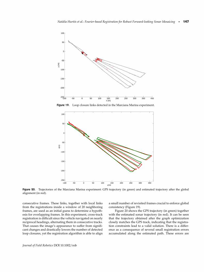
Natalia Hurtos et al.: Fourier-based Registration for Robust Forward-looking Sonar Mosaicing • 147
Figure 19. Loop closure links detected in the Marciana Marina experiment.
Figure 20. Trajectories of the Marciana Marina experiment: GPS trajectory (in green) and estimated trajectory after the globalalignment (in red).
consecutive frames. These links, together with local linksfrom the registrations inside a window of 20 neighboringframes, are used as an initial guess to determine a hypoth-esis for overlapping frames. In this experiment, cross-trackregistration is difficult since the vehicle navigated on nearlyreciprocal headings, alternating them in consecutive tracks.That causes the image’s appearance to suffer from signifi-cant changes and drastically lowers the number of detectedloop closures, yet the registration algorithm is able to align
a small number of revisited frames crucial to enforce globalconsistency (Figure 19).
Figure 20 shows the GPS trajectory (in green) togetherwith the estimated sonar trajectory (in red). It can be seenthat the trajectory obtained after the graph optimizationclosely matches the GPS track, indicating that the registra-tion constraints lead to a valid solution. There is a differ-ence as a consequence of several small registration errorsaccumulated along the estimated path. These errors are
Journal of Field Robotics DOI 10.1002/rob

148 • Journal of Field Robotics—2015
Figure 21. (a) Final mosaic of the Marciana Marina experiment (not oversampled). (b) Orthophotomap of the Marciana Marinaenvironment. Note the presence of common features that can be appreciated in both representations (indicated by red arrows).
distributed along the trajectory; however, since the esti-mated trajectory and the GPS track are fixed with respectto the first position, the error might seem larger at the end.Notice also that the discrepancy is around 15 m, which isbarely 0.7% of the total trajectory. The acoustic mosaic built
using the estimated global positions [shown in Figure 21(a)]presents an overall view of the surveyed area with a con-tinuous and uniform appearance. A result of this type isof special interest not only to observe the harbor featuresand their spatial arrangement but also because it enables
Journal of Field Robotics DOI 10.1002/rob

Natalia Hurtos et al.: Fourier-based Registration for Robust Forward-looking Sonar Mosaicing • 149
us to perceive features that otherwise would be difficult todistinguish given the low resolution and SNR of the acqui-sition sonar.
By georeferencing the mosaic, we can compare it withan orthophotomap of the harbor environment where thesonar data were gathered [Figure 21(b)] and correlate thepresence of scene features (isolated rocks in the left part ofthe image) in both representations.
7. CONCLUSIONS
This paper has described a registration methodology foraligning FLS images, proving its utility in mapping un-derwater environments. The pairwise registration of sonarframes has been solved by a Fourier-based method that,unlike feature-based methods, takes into account all the im-age information in the alignment process. We have tailoredthe phase correlation technique for the special case of FLSimage alignment and have compared its performance withan existing region-based FLS registration method. Our ap-proach has shown superior performance in the alignmentof both consecutive and nonconsecutive frames, provingto be robust and accurate despite the complicated natureof the sonar images. The main restriction of the methodis that it can only register images that differ in small ori-entations. Although this is not an issue in consecutive ornear-consecutive frame registrations, it should be taken intoaccount to obtain successful loop closures.
The registration method has been integrated in a mo-saicing pipeline with global alignment being performedby means of a pose-based graph optimization. The highframe rate of the sonar is exploited to achieve local ro-bustness in the initial guess of the graph, and loop closuresituations are detected and incorporated to enforce globalconsistency.
Reported results include mosaics of different charac-teristics, ranging from small-sized objects to large naturalenvironments, gathered with different sonar models and il-lustrated with application environments typically affectedby low-visibility conditions.
Due to the increase in SNR and resolution with respectto individual frames, the rendered mosaics can serve as anenhanced basis to perform subsequent processing in otherapplications such as object recognition or terrain classifi-cation. In a parallel work, we have started to exploit theadvantage of mosaiced frames to apply pattern matchingwith higher reliability than by using single frames (Hurtos,Palomeras, & Salvi, 2013c).
It is worth pointing out that although the present workfocuses on the offline generation of acoustic mosaics, theproposed registration method has the potential of runningin real time. Future work will concentrate on integratingthe method in an online SLAM framework to help con-strain the dead-reckoning drift and thus enable long-termautonomous operations in turbid environments.
ACKNOWLEDGMENTS
This work has been supported by the FP7-ICT-2011-7 projectPANDORA-Persistent Autonomy through Learning, Adap-tation, Observation and Re-planning (Ref. 288273) fundedby the European Commission, and the Spanish Project AN-DREA/RAIMON (Ref. CTM2011-29691-C02-02) funded bythe Ministry of Science and Innovation. The authors wouldlike to thank Soundmetrics Corp., Bluefin Robotics Corp.and the Centre for Maritime Research and Experimentation(CMRE) for providing some of the sonar data.
REFERENCES
ANFFT Package. (2013). Retrieved December 31, 2013, fromhttps://code.google.com/p/anfft.
Aykin, M., & Negahdaripour, S. (2012). On feature extractionand region matching for forward scan sonar imaging.Oceans, 1–9.
Aykin, M. D., & Negahdaripour, S. (2013). On feature matchingand image registration for two-dimensional forward-scansonar imaging. Journal of Field Robotics, 30(4), 602–623.
Balci, M., & Foroosh, H. (2006). Subpixel estimation of shiftsdirectly in the Fourier domain. IEEE Transactions on ImageProcessing, 15(7), 1965–1972.
Baumgartner, L. J., & Wales, N. S. (2006). Assessment of a dual-frequency identification sonar (DIDSON) for applicationin fish migration studies. NSW Department of PrimaryIndustries.
Biber, P., & Straßer, W. (2003). The normal distributions trans-form: A new approach to laser scan matching. In Pro-ceedings of the IEEE/RSJ International Conference on In-telligent Robots and Systems, 2003 (IROS 2003) (vol. 3,pp. 2743–2748). IEEE.
Bluefin Robotics, Corp. (2013). Retrieved December 31, 2013,from http://www.bluefinrobotics.com.
BlueView Technologies, Inc. (2013). Retrieved December 31,2013, from http://www.blueview.com.
Bulow, H., & Birk, A. (2011). Spectral registration of volumedata for 6-DOF spatial transformations plus scale. In Pro-ceedings of the IEEE International Conference on Roboticsand Automation (ICRA) (pp. 3078–3083).
Bulow, H., Birk, A., & Unnithan, V. (2009). Online generation ofan underwater photo map with improved Fourier Mellinbased registration. OCEANS 2009–EUROPE, 1–6.
Bulow, H., Pfingsthorn, M., & Birk, A. (2010). Using robustspectral registration for scan matching of sonar range data.In 7th Symposium on Intelligent Autonomous Vehicles(IAV). IFAC.
Chailloux, C. (2005). Region of interest on SONAR imagefor non symbolic registration. In Proceedings MTS/IEEEOCEANS (pp. 1–5).
Chen, Q.-S., Defrise, M., & Deconinck, F. (1994). Symmetricphase-only matched filtering of Fourier-Mellin transformsfor image registration and recognition. IEEE Transactionson Pattern Analysis and Machine Intelligence, 16(12),1156–1168.
Journal of Field Robotics DOI 10.1002/rob

150 • Journal of Field Robotics—2015
Costello, C. (2008). Multi-reference frame image registrationfor rotation, translation, and scale. Technical report, DTICDocument.
De Castro, E., & Morandi, C. (1987). Registration of translatedand rotated images using finite Fourier transforms. IEEETransactions on Pattern Analysis and Machine Intelligence5, 700–703.
Elibol, A., Gracias, N., Garcia, R., Gleason, A., Gintert, B.,Lirman, D., & Reid, R. P. (2011). Efficient autonomous im-age mosaicing with applications to coral reef monitoring.In Proceedings of the Workshop on Robotics for Environ-mental Monitoring held at IEEE/RSJ IROS, San Francisco(pp. 50–57).
Eustice, R., Pizarro, O., Singh, H., & Howland, J. (2002). UWIT:Underwater image toolbox for optical image processingand mosaicking in MATLAB. In Proceedings of the In-ternational Underwater Technology Symposium (pp. 141–145).
Eustice, R. M., Pizarro, O., & Singh, H. (2008). Visu-ally augmented navigation for autonomous underwa-ter vehicles. IEEE Journal of Oceanic Engineering, 33(2),103–122.
Fairfield, N., Jonak, D., Kantor, G. A., & Wettergreen, D. (2007).Field results of the control, navigation, and mapping sys-tems of a hovering AUV. In Proceedings of the 15th In-ternational Symposium on Unmanned Untethered Sub-mersible Technology, Durham, NH, USA.
Fischler, M., & Bolles, R. (1981). Random sample consensus:A paradigm for model fitting with applications to imageanalysis and automated cartography. Communications ofthe ACM, 24(6), 381–395.
Foroosh, H., Zerubia, J. B., & Berthod, M. (2002). Extension ofphase correlation to subpixel registration. IEEE Transac-tions on Image Processing, 11(3), 188–200.
Galceran, E., Djapic, V., Carreras, M., & Williams, D. P. (2012). Areal-time underwater object detection algorithm for multi-beam forward looking sonar. In IFAC’s workshop on Nav-igation, Guidance and Control of Underwater Vehicles(NGCUV), Porto, Portugal.
Gracias, N. R., Van Der Zwaan, S., Bernardino, A., & Santos-Victor, J. (2003). Mosaic-based navigation for autonomousunderwater vehicles. IEEE Journal of Oceanic Engineering,28(4), 609–624.
Hoge, W. S. (2003). A subspace identification extension to thephase correlation method [MRI application]. IEEE Trans-actions on Medical Imaging, 22(2), 277–280.
Hover, F. S., Eustice, R. M., Kim, A., Englot, B., Johannsson,H., Kaess, M., & Leonard, J. J. (2012). Advanced percep-tion, navigation and planning for autonomous in-watership hull inspection. The International Journal of RoboticsResearch, 31(12), 1445–1464.
Hurtos, N., Cufi, X., Petillot, Y., & Salvi, J. (2012). Fourier-basedregistrations for two-dimensional forward-looking sonarimage mosaicing. In IEEE/RSJ International Conferenceon Intelligent Robots and Systems (IROS 2012) (pp. 5298–5305). IEEE.
Hurtos, N., Cufı, X., & Salvi, J. (2013a). A novel blending tech-nique for two dimensional forward looking sonar mo-saicking. In IEEE/MTS OCEANS 2013, San Diego.
Hurtos, N., Cufı, X., & Salvi, J. (2014). Rotation estimation fortwo-dimensional forward-looking sonar mosaicing. In Ar-mada, M. A., Sanfeliu, A., & Ferre, M. (eds.), ROBOT2013:First Iberian Robotics Conference, vol. 252 of Advances inIntelligent Systems and Computing (pp. 69–84). SpringerInternational Publishing.
Hurtos, N., Nagappa, S., Cufı, X., Petillot, Y., & Salvi, J. (2013b).Evaluation of registration methods on two-dimensionalforward-looking sonar imagery. In MTS/IEEE Oceans2013, Bergen.
Hurtos, N., Palomeras, N., & Salvi, J. (2013c). Automatic de-tection of underwater chain links using a forward-lookingsonar. In MTS/IEEE Oceans 2013, Bergen.
Johannsson, H., Kaess, M., Englot, B., Hover, F., & Leonard, J.(2010). Imaging sonar-aided navigation for autonomousunderwater harbor surveillance. In Procedings of theIEEE/RSJ International Conference on Intelligent Robotsand Systems (IROS), (pp. 4396–4403).
Kaess, M., Ranganathan, A., & Dellaert, F. (2008). iSAM: In-cremental smoothing and mapping. IEEE Transactions onRobotics, 24(6), 1365–1378.
Keller, Y., Shkolnisky, Y., & Averbuch, A. (2005). The angulardifference function and its application to image registra-tion. IEEE Transactions on Pattern Analysis and MachineIntelligence, 27(6), 969–976.
Kim, K., Intrator, N., & Neretti, N. (2004). Image registration andmosaicing of noisy acoustic camera images. In Proceedingsof the 11th IEEE International Conference on Electronics,Circuits and Systems, ICECS 2004 (pp. 527–530).
Kim, K., Neretti, N., & Intrator, N. (2005). Mosaicing of acousticcamera images. IEE Proceedings–Radar, Sonar and Navi-gation, 152(4), 263–270.
Kinsey, J., Eustice, R., & Whitcomb, L. (2006). A survey of un-derwater vehicle navigation: Recent advances and newchallenges. In Proceedings of the 7th IFAC Conference onManoeuvring and Control of Marine Crafts, Lisbon, Por-tugal.
Kummerle, R., Grisetti, G., Strasdat, H., Konolige, K., &Burgard, W. (2011). g2o: A general framework for graphoptimization. In Proceedings of the IEEE InternatinoalRobotics and Automation (ICRA) Conference (pp. 3607–3613).
Leonard, J., Bennett, A., Smith, C., & Feder, H. (1998). Au-tonomous underwater vehicle navigation. Technical mem-orandum 98-1. MIT Marine Robotics Laboratory.
Li, L., Qu, Z., Zeng, Q., & Meng, F. (2007). A novel approachto image roto-translation estimation. In IEEE InternationalConference on Automation and Logistics (pp. 2612–2616).
Lirman, D., Gracias, N., Gintert, B., Gleason, A., Deangelo, G.,Dick, M., Martinez, E., & Reid, R. (2010). Damage and re-covery assessment of vessel grounding injuries on coralreef habitats by use of georeferenced landscape video mo-saics. Limnology and Oceanography: Methods, 8, 88–97.
Journal of Field Robotics DOI 10.1002/rob

Natalia Hurtos et al.: Fourier-based Registration for Robust Forward-looking Sonar Mosaicing • 151
Lowe, D. (2004). Distinctive image features from scale-invariantkeypoints. International Journal of Computer Vision, 60(2),91–110.
Lucchese, L., & Cortelazzo, G. M. (2000). A noise-robust fre-quency domain technique for estimating planar roto-translations. IEEE Transactions on Signal Processing, 48(6),1769–1786.
More, J. J. (1978). The Levenberg-Marquardt algorithm: Imple-mentation and theory. In Numerical analysis (pp. 105–116).Springer.
Negahdaripour, S. (2012a). On 3-D scene interpretationfrom FS sonar imagery. In MTS/IEEE Oceans, 2012(pp. 1–9).
Negahdaripour, S. (2012b). Visual motion ambiguities of aplane in 2-D FS sonar motion sequences. Computer Visionand Image Understanding, 116(6), 754–764.
Negahdaripour, S., Aykin, M. D., & Sinnarajah, S. (2011). Dy-namic scene analysis and mosaicing of benthic habitats byfs sonar imaging—issues and complexities. In Proceedingsof OCEANS 2011 (pp. 1–7).
Negahdaripour, S., & Firoozfam, P. (2006). An ROV stereovisionsystem for ship-hull inspection. IEEE Journal of OceanicEngineering, 31(3), 551–564.
Negahdaripour, S., Firoozfam, P., & Sabzmeydani, P. (2005). Onprocessing and registration of forward-scan acoustic videoimagery. In Proceedings of the 2nd Canadian Conferenceon Computer and Robot Vision (pp. 452–459).
Negahdaripour, S., Sekkati, H., & Pirsiavash, H. (2009). Opti-acoustic stereo imaging: On system calibration and 3-Dtarget reconstruction. IEEE Transactions on Image Process-ing, 18(6), 1203–1214.
Pfingsthorn, M., Birk, A., Schwertfeger, S., Bulow, H., & Pathak,K. (2010). Maximum likelihood mapping with spectralimage registration. In Proceedings of the IEEE Interna-tional Conference on Robotics and Automation (ICRA)(pp. 4282–4287).
Point Cloud Library (2013). Retrieved December 31, 2013, fromhttp://www.pointclouds.org.
Reddy, B. S., & Chatterji, B. N. (1996). An FFT-based techniquefor translation, rotation, and scale-invariant image regis-tration. IEEE Transactions on Image Processing, 5(8), 1266–1271.
Ren, J., Jiang, J., & Vlachos, T. (2010). High-accuracy sub-pixelmotion estimation from noisy images in Fourier domain.IEEE Transactions on Image Processing, 19(5), 1379–1384.
Ribas, D., Palomeras, N., Ridao, P., Carreras, M., & Mallios,A. (2012). Girona 500 AUV: From survey to interven-tion. IEEE/ASME Transactions on Mechatronics, 17(1),46–53.
Roman, C., & Singh, H. (2005). Improved vehicle based multi-beam bathymetry using sub-maps and SLAM. In Proceed-ings of the IEEE/RSJ International Conference on Intel-ligent Robots and Systems (pp. 3662–3669), Edmonton,Canada.
Schwertfeger, S., Bulow, H., & Birk, A. (2010). On the effectsof sampling resolution in improved Fourier Mellin basedregistration for underwater mapping. In 7th Symposiumon Intelligent Autonomous Vehicles (IAV). IFAC.
Sekkati, H., & Negahdaripour, S. (2007). 3-D motion estimationfor positioning from 2-D acoustic video imagery. In PatternRecognition and Image Analysis (pp. 80–88). Springer.
Smith, R. C., & Cheeseman, P. (1986). On the representation andestimation of spatial uncertainty. The International Journalof Robotics Research, 5(4), 56–68.
Sound Metrics ARIS (2013). Retrieved December 31, 2013, fromhttp://www.soundmetrics.com/Products/ARIS-Sonars/ARIS-Explorer-3000.
Sound Metrics DIDSON (2013). Retrieved December 31,2013, from http://www.soundmetrics.com/Products/DIDSON-Sonars.
Soundmetrics Corp. (2013). Retrieved December 31, 2013, fromhttp://www.soundmetrics.com.
Tena, I., Reed, S., Petillot, Y., Bell, J., & Lane, D. M. (2003). Con-current mapping and localisation using side-scan sonarfor autonomous navigation. In Proceedings of the 13thInternational Symposium on Unmanned Untethered Sub-mersible Technology, Durham, NH.
Tritech Gemini (2013). Retrieved December 31, 2013, fromhttp://www.tritech.co.uk/product/gemini-720i-300m-multibeam-imaging-sonar.
Tuytelaars, T., & Mikolajczyk, K. (2008). Local invariant featuredetectors: A survey. Foundations and Trends R© in Com-puter Graphics and Vision, 3(3), 177–280.
Vaganay, J., Elkins, M., Willcox, S., Hover, F., Damus, R., Desset,S., Morash, J., & Polidoro, V. (2005). Ship hull inspectionby hull-relative navigation and control. In OCEANS, 2005.Proceedings of MTS/IEEE (pp. 761–766).
Vandrish, P., Vardy, A., Walker, D., & Dobre, O. A. (2011).Side-scan sonar image registration for AUV navigation.In Proceedings of the IEEE Symposium on UnderwaterTechnology (UT) and 2011 Workshop on Scientific Use ofSubmarine Cables and Related Technologies (SSC) (pp. 1–7).
Walter, M. (2008). Sparse Bayesian information filters for local-ization and mapping. PhD thesis, Massachusetts Instituteof Technology.
Zitova, B., & Flusser, J. (2003). Image registration methods: Asurvey. Image and Vision Computing, 21(11), 977–1000.
Journal of Field Robotics DOI 10.1002/rob