four views of a computer - uc santa barbarastrukov/ece152bspring2012/notes/files/03_hj_c… · four...
TRANSCRIPT

Page 1
Four Views of a Computer
• The user’s view• The user s view• The programmer’s view• The architect’s view• The hardware designer’s view
The User’s View of a Computer
The user sees form factors, software, speed, storage capacity, and peripheral device functionality.
Page 2
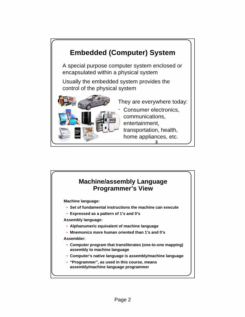
Embedded (Computer) System
A special purpose computer system enclosed or encapsulated within a physical systemp p y y
Usually the embedded system provides the control of the physical system
They are everywhere today:• Consumer electronics
3
Consumer electronics, communications, entertainment, transportation, health, home appliances, etc.
Machine/assembly Language Programmer’s View
Machine language:S t f f d t l i t ti th hi t• Set of fundamental instructions the machine can execute
• Expressed as a pattern of 1’s and 0’s Assembly language:
• Alphanumeric equivalent of machine language• Mnemonics more human oriented than 1’s and 0’s
Assembler:• Computer program that transliterates (one-to-one mapping)
assembly to machine language• Computer’s native language is assembly/machine language• “Programmer”, as used in this course, means
assembly/machine language programmer

Page 3
The Fetch-Execute Cycle
Programmer’s Model:Instruction Set Architecture (ISA)
• Instruction set: the collection of all machine operations.p• Programmer sees set of instructions, along with the
machine resources manipulated by them.• ISA includes
• instruction set, • memory, and • programmer accessible registers of the system.p g g y
• There may be temporary or scratch-pad memory used to implement some function is not part of ISA.
• “Non Programmer Accessible.”

Page 4
Fig 1.3 Programmer’s Models of 4 commercial machines
The Computer Architect’s View
• Architect is concerned with design & performanceg p• Designs the ISA for optimum programming utility and
optimum performance of implementation• Designs the hardware for best implementation of the
instructions• Uses performance measurement tools, such as benchmark
programs, to see that goals are met• Balances performance of building blocks such as CPU,
memory, I/O devices, and interconnections• Meets performance goals at lowest cost
Page 5
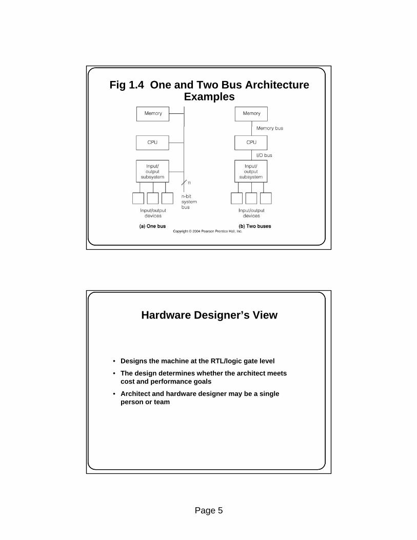
Fig 1.4 One and Two Bus Architecture Examples
Hardware Designer’s View
• Designs the machine at the RTL/logic gate level
• The design determines whether the architect meets cost and performance goals
• Architect and hardware designer may be a single person or team

Page 6
Two Views of the CPU PC Register
31 0PCP PCProgrammer:
D Q3232
PCoutPC
A BusB Bus
Hardware Designer(Fig 1 8):
PCinCK
(Fig 1.8):
Chapter 2: Machines, Machine Languages, and Digital Logic
TopicsTopics
2.1 Classification of Computers and Their Instructions2.2 Computer Instruction Sets2.3 Informal Description of the Simple RISC Computer, SRC2.4 Formal Description of SRC Using Register Transfer Notation,
RTN2.5 Describing Addressing Modes with RTN2.6 Register Transfers and Logic Circuits: From Behavior to
Hardware

Page 7
What Are the Components of an ISA?Sometimes known as The Programmer’s Model of the machineStorage cells
• General and special purpose registers in the CPU• General and special purpose registers in the CPU• Many general purpose cells of same size in memory• Storage associated with I/O devices
The machine instruction set• The instruction set is the entire repertoire of machine operations• Makes use of storage cells, formats, and results of the
fetch/execute cycle• i.e., register transfers
The instruction format• Size and meaning of fields within the instruction
Programmer’s Models of Various Machines

Page 8
Which operation to perform add r0, r1, r3
What Must an Instruction Specify?
Data Flow
p p• Ans: Op code: add, load, branch, etc.
Where to find the operand or operands add r0, r1, r3• In CPU registers, memory cells, I/O locations, or part of
instructionPlace to store result add r0, r1, r3
• Again CPU register or memory cellL ti f t i t ti dd 0 1 3Location of next instruction add r0, r1, r3
br endloop• Almost always memory cell pointed to by program counter—PC
Instructions Can Be Divided into 3 Classes
Data movement instructions• Move data from a memory location or register to another
memory location or register without changing its formy g g g• Load—source is memory and destination is register• Store—source is register and destination is memory
Arithmetic and logic (ALU) instructions• Change the form of one or more operands to produce a result
stored in another location• Add, Sub, Shift, etc.
Branch instructions (control flow instructions)( )• Alter the normal flow of control from executing the next
instruction in sequence• Br Loc, Brz Loc2,—unconditional or conditional branches

Page 9
Examples of Data Movement Instructions
Instruction Meaning Machine
MOV A, B Move 16 bits from memory location A to VAX11 , yLocation B
LDA A, Addr Load accumulator A with the byte at memory M6800 location Addr
lwz R3, A Move 32-bit data from memory location A to PPC601 register R3
li $3, 455 Load the 32-bit integer 455 into register $3 MIPS R3000
M 16 bit d t f t t t t DEC PDP11
Lots of variation, even with one instruction type
mov R4, dout Move 16-bit data from R4 to output port dout DEC PDP11
IN, AL, KBD Load a byte from in port KBD to accumulator Intel Pentium
LEA.L (A0), A2 Load the address pointed to by A0 into A2 M6800
Examples of ALU Instructions
Instruction Meaning MachineMULF A, B, C multiply the 32-bit floating point values at VAX11
mem loc’ns. A and B, store at Cnabs r3, r1 Store abs value of r1 in r3 PPC601ori $2, $1, 255 Store logical OR of reg $ 1 with 255 into reg $2 MIPS R3000DEC R2 Decrement the 16-bit value stored in reg R2 DEC PDP11SHL AX, 4 Shift the 16-bit value in reg AX left by 4 bit pos’ns. Intel 8086
• Notice again the complete dissimilarity of both syntax and semantics.

Page 10
Examples of Branch Instructions
Instruction Meaning MachineBLSS A, Tgt Branch to address Tgt if the least significant VAX11
bit of mem loc’n. A is set (i.e. = 1)bun r2 Branch to location in R2 if result of previous PPC601
floating point computation was Not a Number (NAN)beq $2, $1, 32 Branch to location (PC + 4 + 32) if contents MIPS R3000
of $1 and $2 are equalof $1 and $2 are equalSOB R4, Loop Decrement R4 and branch to Loop if R4 ≠ 0 DEC PDP11JCXZ Addr Jump to Addr if contents of register CX ≠ 0. Intel 8086
3-, 2-, 1-, & 0-Address ISAsClassification is based on arithmetic instructions that have two operands and one resultThe key issue is “how many of these are specified by memory
dd d t b i ifi d i li itl ”addresses, as opposed to being specified implicitly”A 3-address instruction specifies memory addresses for both operands and the result R ← Op1 op Op2A 2-address instruction overwrites one operand in memory with the result Op2 ← Op1 op Op2A 1-address instruction has a processor, called the accumulator register, to hold one operand & the result (no addr. needed) Acc ← Acc op Op1Acc ← Acc op Op1A 0-address + uses a CPU register stack to hold both operands and the result TOS ← TOS op SOS (where TOS is Top Of Stack, SOS is Second On Stack)The 4-address instruction, hardly ever seen, also allows the address of the next instruction to specified explicitly

Page 11
The 4-Address Machine and Instruction Format
Memory
Op1Addr:Op2Addr:
Op1Op2
CPU add, Res, Op1, Op2, Nexti (Res ← Op1 + Op2)
Op2Addr: Op2
ResAddr:
NextiAddr:
Bits: 8 24 24
Instruction format
24 24
Res
Nexti
Explicit addresses for operands, result, & next instructionExample assumes 24-bit addresses
• Discuss: size of instruction in bytes
add ResAddr Op1Addr Op2Addr NextiAddrWhich
operationWhere toput result Where to find operands
Where to findnext instruction
The 3-Address Machine and Instruction Format
Memory
Op1Addr:Op2Addr:
Op1Op2
CPU add, Res, Op1, Op2 (Res ← Op2 + Op1)
Programcounter
ResAddr:
NextiAddr:
Bits: 8 24 24Instruction format
24
Res
NextiWhere to find
next instruction
24
Address of next instruction kept in processor state register—the PC (except for explicit branches/jumps)Rest of addresses in instruction
• Discuss: savings in instruction word size
add ResAddr Op1Addr Op2AddrWhich
operationWhere toput result Where to find operands

Page 12
The 2-Address Machine and Instruction Format
Memory
Op1Addr: Op1
CPU add Op2, Op1 (Op2 ← Op2 + Op1)
Op2Addr:
Programcounter
Op2,Res
NextiNextiAddr:
Bits: 8 24 24Instruction format
Where to findnext instruction
24
Result overwrites Operand 2Needs only 2 addresses in instruction but less choice in placing data
Bits: 8 24 24
add Op2Addr Op1AddrWhich
operation
Where toput result
Where to find operands
1-Address Machine and Instruction Format
Memory
Op1Addr: Op1
CPU add Op1 (Acc ← Acc + Op1)
Need instructions to load
NextiProgramcounter
Accumulator
NextiAddr:
Where to findnext instruction
24
Where to findoperand2, and
where to put result
Special CPU register, the accumulator, supplies 1 operand and stores resultOne memory address used for other operand
Need instructions to load and store operands:LDA OpAddrSTA OpAddr
Bits: 8 24Instruction format
add Op1AddrWhich
operationWhere to find
operand1

Page 13
The 0-Address, or Stack, Machine and Instruction Format
Memory
Bits: 8 24
CPU push Op1 (TOS ← Op1)
Instruction formats
Op1Addr:
TOSSOSetc.
Op1
Programcounter
NextiAddr: Nexti
Bits:
Format
Format
8 24
Where to find
Stack
24
add (TOS ← TOS + SOS)
push Op1AddrOperation
Bits: 8
addWhich operation
Result
Uses a push-down stack in CPUComputer must have a 1-address instruction to push and pop operands to and from the stack
Where to findnext instruction
Where to find operands,and where to put result
(on the stack)
Example 2.1 Expression Evaluation for 3-, 2-, 1-, and 0-Address Machines
Evaluate a = (b+c)*d - e
3 - a d d r e s s 2 - a d d r e s s 1 - a d d r e s s S t a c k
add a, b, cmpy a, a, dsub a, a, e
load a, badd a, cmpy a, dsub a, e
load badd cmpy dsub et
push bpush caddpush d
Evaluate a (b+c) d e
Number of instructions & number of addresses both varyDiscuss as examples: size of code in each case
store a mpypush esubpop a
Page 14
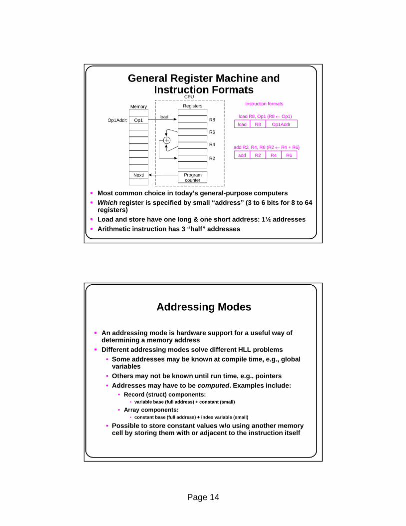
General Register Machine and Instruction Formats
Memory
Op1Addr: Op1load load R8, Op1 (R8 ← Op1)
CPU
Registers
R8
Instruction formats
R8load Op1Addr
Nexti Programcounter
R6
R4
R2
R8load Op1Addr
add R2, R4, R6 (R2 ← R4 + R6)
R2add R6R4
Most common choice in today’s general-purpose computersWhich register is specified by small “address” (3 to 6 bits for 8 to 64 registers)Load and store have one long & one short address: 1½ addressesArithmetic instruction has 3 “half” addresses
Addressing Modes
An addressing mode is hardware support for a useful way of determining a memory addressdetermining a memory addressDifferent addressing modes solve different HLL problems
• Some addresses may be known at compile time, e.g., global variables
• Others may not be known until run time, e.g., pointers• Addresses may have to be computed. Examples include:
• Record (struct) components:• variable base (full address) + constant (small)• variable base (full address) + constant (small)
• Array components:• constant base (full address) + index variable (small)
• Possible to store constant values w/o using another memory cell by storing them with or adjacent to the instruction itself

Page 15
Common Addressing Modes a-d
Common Addressing Modes e-g
Page 16
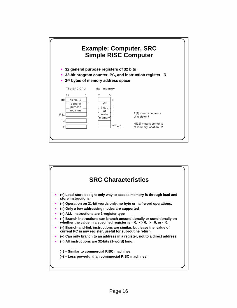
32 general purpose registers of 32 bits
Example: Computer, SRCSimple RISC Computer
32-bit program counter, PC, and instruction register, IR232 bytes of memory address space
R0
The SRC CPU Main m em ory
31 70 0
032 32-bitgeneralpurpose
232
bytes
R31
PC
IR
R[7] means contentsof register 7
M[32] means contentsof memory location 32232 – 1
purposeregisters
bytesof
mainmemory
SRC Characteristics
(=) Load-store design: only way to access memory is through load and store instructions(–) Operation on 21-bit words only, no byte or half-word operations.(=) Only a few addressing modes are supported(=) ALU Instructions are 3-register type(–) Branch instructions can branch unconditionally or conditionally on whether the value in a specified register is = 0, <> 0, >= 0, or < 0.(–) Branch-and-link instructions are similar, but leave the value of current PC in any register, useful for subroutine return.( ) C l b h t dd i i t t t di t dd(–) Can only branch to an address in a register, not to a direct address.(=) All instructions are 32-bits (1-word) long.
(=) – Similar to commercial RISC machines(–) – Less powerful than commercial RISC machines.

Page 17
SRC Basic Instruction Formats
There are three basic instruction format typesThe number of register specifier fields and length of the g p gconstant field varyOther formats result from unused fields or partsDetails of formats on next slide
31 2726 2221 0op ra c1 Type 1
31 27
27
26
26
22
22
21
2131
1716
1716 1211
0
0
rb
rcrb
ra
ra
op
op
c2
c3
Type 2
Type 3
Total of 7 Detailed Formats
Op1. Id, st, la,addi, andi, ori rb c2
Instruction formats Example
31 27 26 22 21 17 16 0Id r3, AId r3, 4(r5)addi r2, r4, #1
(R[3] = M[A])(R[3] = M[R[5] + 4])
(R[2] = R[4] +1)ra
Op2. Idr, str, lar c131 2726 22 21 0 Idr r5, 8
Iar r6, 45(R[5] = M[PC + 8])(R[6] = PC + 45)ra
Op3. neg, not unused31 27 26 22 21 17 16 0
neg r7, r9 (R[7] = – R[9])ra
unused
rc
Op4. br unused31 27 26 22 21 17 1216 11 2 0 brzr r4, r0
(branch to R[4] if R[0] == 0)rb rc (c3) Cond
Op5. brl unused31 27 26 22 21 17 16 0 brlnz r6, r4, r0
(R[6] = PC; branch to R[4] if R[0] ≠ 0)ra rb rc1211 2
Cond
Op6. add, sub,and, or
unused31 27 26 22 21 17 16 0
add r0, r2, r4 (R[0] = R[2] + R[4])ra rb rc1211
unused
(c3)
(c3)Op unused31 27 26 22 21 17 16 0 shl r2, r4, r6
(R[2] = R[4] shifted left by count in R[6])ra rb rc12 4
00000
(c3)Op7. shr, shrashl, shic
unused31 27 26 22
7a
7b
21 17 0 shr r0, r1, #4(R[0] = R[1] shifted right by 4 bitsra rb
4Count
Op8. nop, stop unused31 27 0
stop26
(c3)
(c3)

Page 18
Example SRC Load and Store Instructions
Address can be constant, constant + register, or constant + PCMemory contents or address itself can be loadedMemory contents or address itself can be loaded
Instruction op ra rb c1 Meaning Addressing Modeld r1, 32 1 1 0 32 R[1] ← M[32] Directld r22, 24(r4) 1 22 4 24 R[22] ← M[24+R[4]] Displacementst r4, 0(r9) 3 4 9 0 M[R[9]] ← R[4] Register indirectla r7, 32 5 7 0 32 R[7] ← 32 Immediateldr r12, -48 2 12 – -48 R[12] ← M[PC -48] Relative
(note use of la to load a constant)
d , R[12] ← M[PC 48] e velar r3, 0 6 3 – 0 R[3] ← PC Register (!)
Assembly Language Forms of Arithmetic and Logic Instructions
Format Example Meaningneg ra, rc neg r1, r2 ;Negate (r1 = -r2) not ra, rc not r2, r3 ;Not (r2 = r3´ )add ra, rb, rc add r2, r3, r4 ;2’s complement additionsub ra, rb, rc ;2’s complement subtractionand ra, rb, rc ;Logical andor ra, rb, rc ;Logical oraddi ra rb c2 addi r1 r3 #1 ;Immediate 2’s complement add
Immediate subtract not needed since constant in addi may be negative
addi ra, rb, c2 addi r1, r3, #1 ;Immediate 2 s complement addandi ra, rb, c2 ;Immediate logical andori ra, rb, c2 ;Immediate logical or

Page 19
Branch Instruction FormatThere are actually only two branch instructions:br rb, rc, c3<2..0> ; branch to R[rb] if R[rc] meets
; the condition defined by c3<2..0>ybrl ra, rb, rc, c3<2..0> ; R[ra] ← PC; branch as above
lsbs condition Assy language form Example000 never brlnv brlnv r6001 always br, brl br r5, brl r5010 if rc = 0 brzr, brlzr brzr r2, r4, r5
• It is c3<2..0>, the 3 lsbs of c3, that governs what the branch condition is:
, , ,011 if rc ≠ 0 brnz, brlnz100 if rc >= 0 brpl, brlpl101 if rc < 0 brmi, brlmi
• Note that branch target address is always in register R[rb]. • It must be placed there explicitly by a previous instruction.
Forms and Formats of the br and brl Instructions
Ass’ylang.
Example instr. Meaning op ra rb rc c3⟨2..0⟩
BranchCond’n.
brlnv brlnv r6 R[6] ← PC 9 6 — — 000 neverbr br r4 PC ← R[4] 8 — 4 — 001 alwaysbrl brl r6,r4 R[6] ← PC;
PC ← R[4]9 6 4 — 001 always
brzr brzr r5,r1 if (R[1]=0)PC ← R[5]
8 — 5 1 010 zero
brlzr brlzr r7,r5,r1 R[7] ← PC; 9 7 5 1 010 zerobrnz brnz r1, r0 if (R[0]≠0) PC← R[1] 8 — 1 0 011 nonzerobrlnz brlnz r2,r1,r0 R[2] ← PC;
if (R[0]≠0) PC← R[1]9 2 1 0 011 nonzero
brpl brpl r3 r2 if (R[2]>=0) PC← R[3] 8 — 3 2 100 plusbrpl brpl r3, r2 if (R[2]>=0) PC← R[3] 8 — 3 2 100 plusbrlpl brlpl r4,r3,r2 R[4] ← PC;
if (R[2]>=0) PC← R[3]9 4 3 2 plus
brmi brmi r0, r1 if (R[1]<0) PC← R[0] 8 — 0 1 101 minusbrlmi brlmi r3,r0,r1 R[3] ← PC;
if (r1<0) PC← R[0]9 3 0 1 minus
Page 20
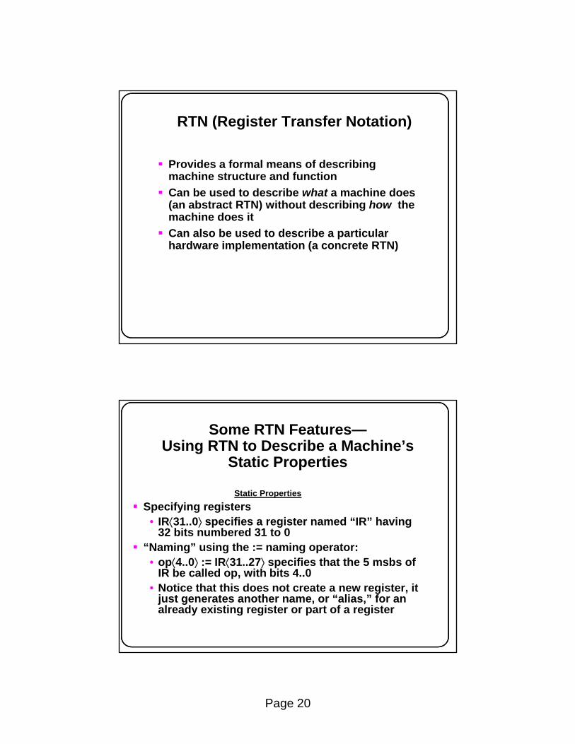
RTN (Register Transfer Notation)
Provides a formal means of describing machine structure and functionmachine structure and functionCan be used to describe what a machine does (an abstract RTN) without describing how the machine does itCan also be used to describe a particular hardware implementation (a concrete RTN)
Some RTN Features—Using RTN to Describe a Machine’s
Static Properties
Static PropertiesSpecifying registers
• IR⟨31..0⟩ specifies a register named “IR” having 32 bits numbered 31 to 0
“Naming” using the := naming operator:• op⟨4..0⟩ := IR⟨31..27⟩ specifies that the 5 msbs of
IR b ll d i h bi 4 0IR be called op, with bits 4..0• Notice that this does not create a new register, it
just generates another name, or “alias,” for an already existing register or part of a register

Page 21
Using RTN to DescribeDynamic Properties
Dynamic Properties• Conditional expressions:
(op=12) → R[ra] ← R[rb] + R[rc]: ; defines the add instruction
“if” condition “then” RTN Assignment Operator
This fragment of RTN describes the SRC add instruction. It says,“when the op field of IR = 12, then store in the register specified by the ra field, the result of adding the register specified by the rb field to the register specified by the rc field.”
Using RTN to Describe the SRC (Static) Processor State
Processor statePC⟨31..0⟩: program counter
(memory addr. of next inst.)IR⟨31..0⟩: instruction registerRun: one bit run/halt indicatorStrt: start signalStrt: start signalR[0..31]⟨31..0⟩: general purpose registers
Page 22
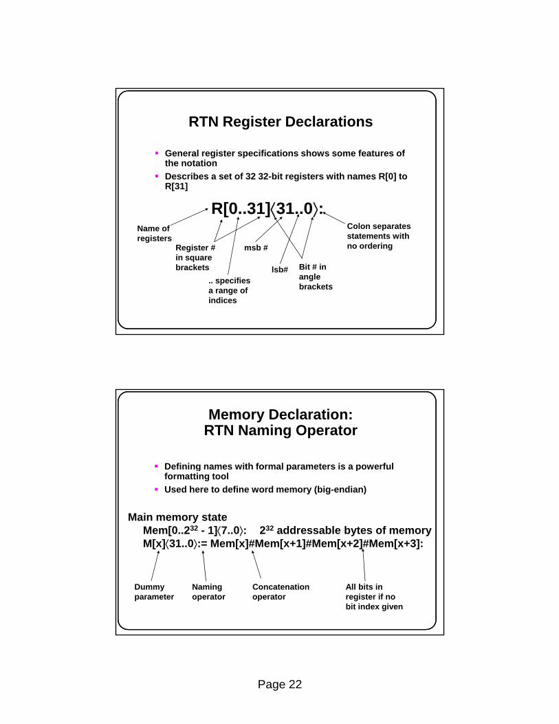
RTN Register Declarations
General register specifications shows some features of the notationDescribes a set of 32 32-bit registers with names R[0] to R[31]
R[0..31]⟨31..0⟩:Name ofregisters
Register # msb #
Colon separatesstatements withno ordering
in squarebrackets
.. specifiesa range ofindices
lsb# Bit # inanglebrackets
Memory Declaration:RTN Naming Operator
Defining names with formal parameters is a powerful g p pformatting toolUsed here to define word memory (big-endian)
Main memory stateMem[0..232 - 1]⟨7..0⟩: 232 addressable bytes of memoryM[x]⟨31..0⟩:= Mem[x]#Mem[x+1]#Mem[x+2]#Mem[x+3]:
Dummyparameter
Namingoperator
Concatenationoperator
All bits inregister if nobit index given

Page 23
RTN Instruction Formatting Uses Renaming of IR Bits
Instruction formatsInstruction formatsop⟨4..0⟩ := IR⟨31..27⟩: operation code fieldra⟨4..0⟩ := IR⟨26..22⟩: target register fieldrb⟨4..0⟩ := IR⟨21..17⟩: operand, address index, or
branch target registerrc⟨4..0⟩ := IR⟨16..12⟩: second operand, conditional
test, or shift count register, gc1⟨21..0⟩ := IR⟨21..0⟩: long displacement fieldc2⟨16..0⟩ := IR⟨16..0⟩: short displacement or
immediate fieldc3⟨11..0⟩ := IR⟨11..0⟩: count or modifier field
Specifying Dynamic Properties of SRC: RTN Gives Specifics of Address
CalculationEffective address calculations (occur at runtime):
Renaming defines displacement and relative addressesNew RTN notation is used
• condition → expression means if condition then
disp⟨31..0⟩ := ((rb=0) → c2⟨16..0⟩ {sign extend}: displacement(rb≠0) → R[rb] + c2⟨16..0⟩ {sign extend, 2's comp.} ): address
rel⟨31..0⟩ := PC⟨31..0⟩ + c1⟨21..0⟩ {sign extend, 2’s comp.}: relativeaddress
• condition → expression means if condition thenexpression
• modifiers in { } describe type of arithmetic or how short numbers are extended to longer ones
• arithmetic operators (+ - * / etc.) can be used in expressionsRegister R[0] cannot be added to a displacement

Page 24
Instruction Interpretation: RTN Description of Fetch-Execute
Need to describe actions (not just declarations)( j )Some new notation:
instruction_interpretation := (R St t R 1
Logical NOTLogical AND
¬Run∧Strt → Run ← 1:Run → (IR ← M[PC]: PC ← PC + 4; instruction_execution) );
Register transfer Separates statementsthat occur in sequence
RTN Sequence and Clocking
In general, RTN statements separated by “:“ take place g p y pduring the same clock pulseStatements separated by “;” take place on successive clock pulsesThis is not entirely accurate since some things written with one RTN statement can take several clocks to performMore precise difference between “:” and “;”
• The order of execution of statements separated by “:” p ydoes not matter
• If statements are separated by “;” the one on the left must be complete before the one on the right starts

Page 25
More About Instruction Interpretation RTN
In the expression IR ← M[PC]: PC ← PC + 4; which value of p [ ]PC applies to M[PC] ?The rule in RTN is that all right hand sides of “:” -separated RTs are evaluated before any LHS is changed
• In logic design, this corresponds to “master-slave” operation of flip-flops
What happens when Run and Strt are both false?• Since no action is specified for this case, the RTN p
implicitly says that no action occurs in this case
Individual Instructions
instruction_interpretation contained a forward _ preference to instruction_executioninstruction_execution is a long list of conditional operations
• The condition is that the op code specifies a given instruction
• The operation describes what that instruction doesNote that the operations of the instruction are done pafter (;) the instruction is put into IR and the PC has been advanced to the next instruction

Page 26
RTN Instruction Execution for Load and Store Instructions
instr ction e ec tion = (instruction_execution := (ld (:= op= 1) → R[ra] ← M[disp]: load registerldr (:= op= 2) → R[ra] ← M[rel]: load register relativest (:= op= 3) → M[disp] ← R[ra]: store registerstr (:= op= 4) → M[rel] ← R[ra]: store register relativela (:= op= 5 ) → R[ra] ← disp: load displacement addresslar (:= op= 6) → R[ra] ← rel: load relative address
The in-line definition (:= op=1) saves writing a separate definition ld := op=1 for the ld mnemonicThe previous definitions of disp and rel are needed to understand all the details
SRC RTN—The Main Loop
ii := instruction_interpretation: ie := instruction_execution : ii := ( ¬Run∧Strt → Run ← 1:
Run → (IR ← M[PC]: PC ← PC + 4; ie) );
ie := (ld (:= op= 1) → R[ra] ← M[disp]: Big switchldr (:= op= 2) → R[ra] ← M[rel]: statement
on the opcode. . . on the opcodestop (:= op= 31) → Run ← 0:
); ii
Thus ii and ie invoke each other, as coroutines.
Page 27
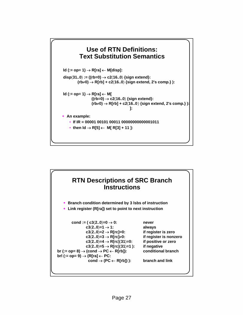
Use of RTN Definitions:Text Substitution Semantics
ld (:= op= 1) → R[ra] ← M[disp]:
disp⟨31..0⟩ := ((rb=0) → c2⟨16..0⟩ {sign extend}:(rb≠0) → R[rb] + c2⟨16..0⟩ {sign extend, 2's comp.} ):
ld (:= op= 1) → R[ra] ← M[((rb=0) → c2⟨16..0⟩ {sign extend}:(rb≠0) → R[rb] + c2⟨16..0 ⟩ {sign extend, 2's comp.} ):
]:
An example:• If IR = 00001 00101 00011 00000000000001011• then ld → R[5] ← M[ R[3] + 11 ]:
]
RTN Descriptions of SRC Branch Instructions
Branch condition determined by 3 lsbs of instructionyLink register (R[ra]) set to point to next instruction
cond := ( c3⟨2..0⟩=0 → 0: neverc3⟨2..0⟩=1 → 1: alwaysc3⟨2..0⟩=2 → R[rc]=0: if register is zeroc3⟨2..0⟩=3 → R[rc]≠0: if register is nonzeroc3⟨2 0⟩=4 R[rc]⟨31⟩=0 if positi e or eroc3⟨2..0⟩=4 → R[rc]⟨31⟩=0: if positive or zeroc3⟨2..0⟩=5 → R[rc]⟨31⟩=1 ): if negative
br (:= op= 8) → (cond → PC ← R[rb]): conditional branchbrl (:= op= 9) → (R[ra] ← PC:
cond → (PC ← R[rb]) ): branch and link
Page 28
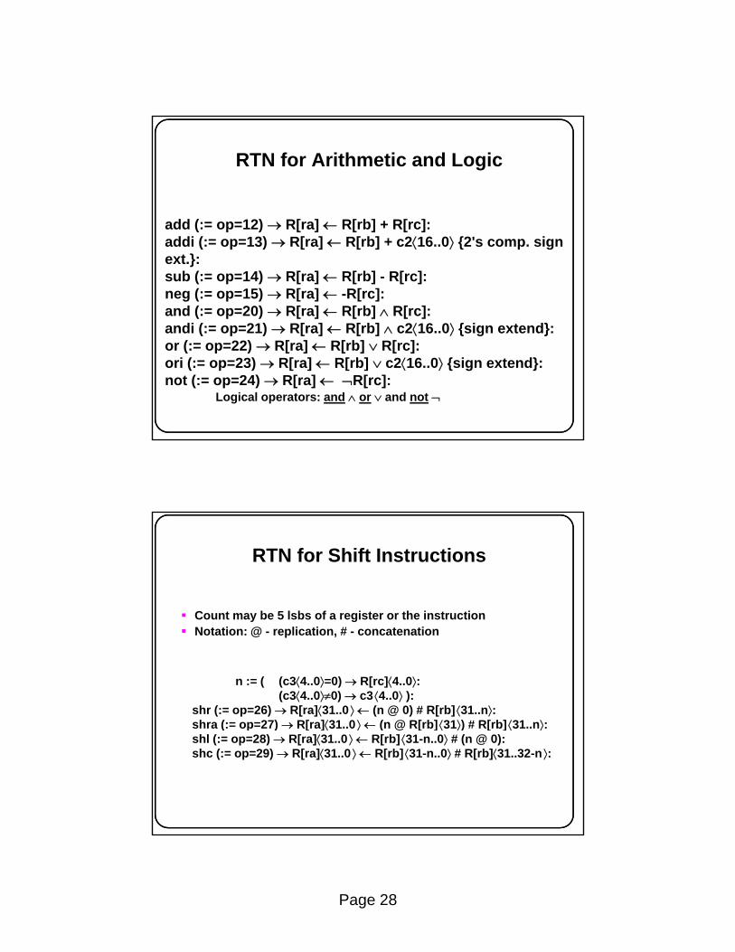
RTN for Arithmetic and Logic
add (:= op=12) → R[ra] ← R[rb] + R[rc]:add (:= op=12) → R[ra] ← R[rb] + R[rc]:addi (:= op=13) → R[ra] ← R[rb] + c2⟨16..0⟩ {2's comp. sign ext.}:sub (:= op=14) → R[ra] ← R[rb] - R[rc]:neg (:= op=15) → R[ra] ← -R[rc]:and (:= op=20) → R[ra] ← R[rb] ∧ R[rc]:andi (:= op=21) → R[ra] ← R[rb] ∧ c2⟨16..0⟩ {sign extend}:
Logical operators: and ∧ or ∨ and not ¬
andi (: op 21) → R[ra] ← R[rb] ∧ c2⟨16..0⟩ {sign extend}:or (:= op=22) → R[ra] ← R[rb] ∨ R[rc]:ori (:= op=23) → R[ra] ← R[rb] ∨ c2⟨16..0⟩ {sign extend}:not (:= op=24) → R[ra] ← ¬R[rc]:
RTN for Shift Instructions
Count may be 5 lsbs of a register or the instructionCount may be 5 lsbs of a register or the instructionNotation: @ - replication, # - concatenation
n := ( (c3⟨4..0⟩=0) → R[rc]⟨4..0⟩:(c3⟨4..0⟩≠0) → c3 ⟨4..0⟩ ):
shr (:= op=26) → R[ra]⟨31..0 ⟩ ← (n @ 0) # R[rb] ⟨31..n⟩:shra (:= op=27) → R[ra]⟨31..0 ⟩ ← (n @ R[rb] ⟨31⟩) # R[rb] ⟨31..n⟩:shra (: op 27) → R[ra]⟨31..0 ⟩ ← (n @ R[rb] ⟨31⟩) # R[rb] ⟨31..n⟩:shl (:= op=28) → R[ra]⟨31..0 ⟩ ← R[rb] ⟨31-n..0⟩ # (n @ 0):shc (:= op=29) → R[ra]⟨31..0 ⟩ ← R[rb] ⟨31-n..0⟩ # R[rb]⟨31..32-n ⟩:
Page 29
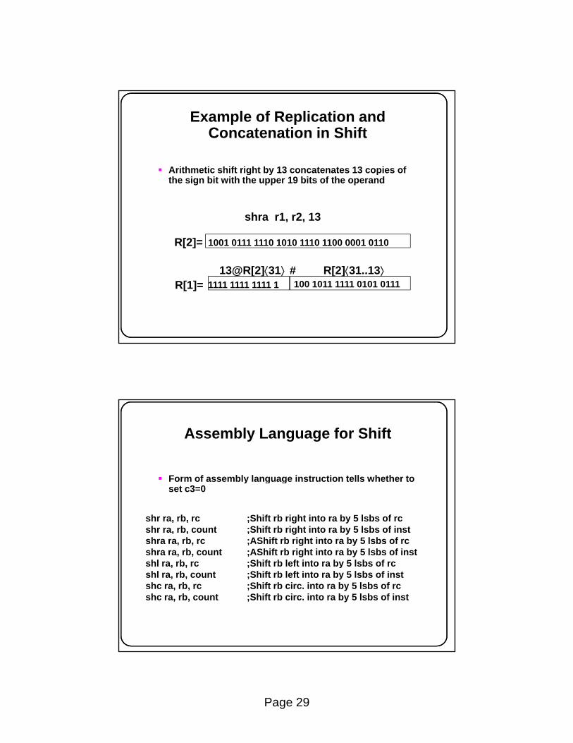
Example of Replication and Concatenation in Shift
Arithmetic shift right by 13 concatenates 13 copies of g y pthe sign bit with the upper 19 bits of the operand
shra r1, r2, 13
1001 0111 1110 1010 1110 1100 0001 0110R[2]=
13@R[2]⟨31⟩ R[2]⟨31..13⟩100 1011 1111 0101 0111
#1111 1111 1111 1R[1]=
Assembly Language for Shift
Form of assembly language instruction tells whether to y g gset c3=0
shr ra, rb, rc ;Shift rb right into ra by 5 lsbs of rcshr ra, rb, count ;Shift rb right into ra by 5 lsbs of instshra ra, rb, rc ;AShift rb right into ra by 5 lsbs of rcshra ra, rb, count ;AShift rb right into ra by 5 lsbs of instshl ra, rb, rc ;Shift rb left into ra by 5 lsbs of rc, , ; yshl ra, rb, count ;Shift rb left into ra by 5 lsbs of instshc ra, rb, rc ;Shift rb circ. into ra by 5 lsbs of rcshc ra, rb, count ;Shift rb circ. into ra by 5 lsbs of inst

Page 30
End of RTN Definition of instruction_execution
nop ( = op= 0) No operation
We will find special use for nop in pipeliningThe machine waits for Strt after executing stop
nop (:= op= 0) → : No operationstop (:= op= 31) → Run ← 0: Stop instruction ); End of instruction_executioninstruction_interpretation.
The long conditional statement defining instruction_execution ends with a direction to go repeat instruction_interpretation, which will fetch and execute the next instruction (if Run still =1)
Confused about RTN and SRC?
SRC is a Machine Language• It can be interpreted by either hardware or p y
software simulator.RTN is a Specification Language
• Specification languages are languages that are used to specify other languages or systems—a metalanguage.
• Other examples: LEX, YACC, VHDL, VerilogVerilog

Page 31
The Relationship of RTN to SRC
SRC specification written in RTN
RTN compiler
Generated processor
SRC program
and data
Data outputSRC interpreter
or simulator
A Note About Specification Languages
They allow the description of what without having to specify how.They allow precise and unambiguous specifications, unlike natural language.They reduce errors:
Errors due to misinterpretation of imprecise specifications written in natural language.Errors due to confusion in design and o s due to co us o des g a dimplementation—“human error.”
Now the designer must debug the specification!

Page 32
Addressing Modes Described in RTN (Not SRC)
Mode name Assembler RTN meaning UseS t
Target register
SyntaxRegister Ra R[t] ← R[a] Tmp. Var.Register indirect (Ra) R[t] ← M[R[a]] PointerImmediate #X R[t] ← X ConstantDirect, absolute X R[t] ← M[X] Global Var.Indirect (X) R[t] ← M[ M[X] ] Pointer Var.Indexed, based, X(Ra) R[t] ← M[X + R[a]] Arrays, structsor displacementRelative X(PC) R[t] ← M[X + PC] Vals stored w pgmRelative X(PC) R[t] ← M[X + PC] Vals stored w pgmAutoincrement (Ra)+ R[t] ← M[R[a]]; R[a] ← R[a] + 1 SequentialAutodecrement - (Ra) R[a] ← R[a] - 1; R[t] ← M[R[a]] access.
Register Transfers Hardware and Timing for a Single-Bit Register
Transfer: A ← BImplementing the RTN statement A ← B
Strobe
B
A
10101
DB
Q
Q
DA
Q
Q
Strobe
(a) Hardware (b) Timing
A 10

Page 33
Multiple Bit Register Transfer: A⟨m..1⟩← B⟨m..1⟩
D1
Q
Q
D1
Q
QQ Q
Strobe
D
B⟨m..1⟩
Q
Q
D
A⟨m..1⟩
Q
Q
D2
Q D2
Q
Dm
Q Dm
Q
Q Q
m
Strobe
(a) Individual flip-flops (b) Abbreviated notation
Strobem m
B A
Q Q
Data Transmission View of Logic Gates
Logic gates can be used to control the transmission of data:g g
Data gate
data
gate
gate→data
gate→0
data 1data1(2),provideddata2(1)is zero
data 2
data 1
Controlled complement
Data merge
data
control
control→data
control→data
is zerodata 1data 2
Page 34
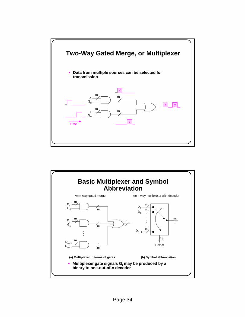
Two-Way Gated Merge, or Multiplexer
Data from multiple sources can be selected for ptransmission
x y
xGx
m
xm
m m
y
yGy
m
Time
Basic Multiplexer and Symbol Abbreviation
D0
An n-way gated merge An n-way multiplexer with decoder
m
D m0
D1
G0
D 1
m
mm
D0
D1m
m
Dn– 1m
k
G1
m m
Multiplexer gate signals Gi may be produced by a binary to one-out-of-n decoder
Gn– 1
Dn– 1
(a) Multiplexer in terms of gates (b) Symbol abbreviation
Selectm

Page 35
Separating Merged Data
x yx
m0
x y
Gx
m
Time
Merged data can be separated by gating at the right timeIt can also be strobed into a flip-flop when valid
Time
Multiplexed Register Transfers Using Gates and Strobes
Hold time
mmD Q
mD Q
GC
SA
SB
GC
P ti ti
SB
CQ
mmm
DD
Q
Q
AQ
DB
Q
Q
m
Selected gate and strobe determine which RTA←C and B←C can occur together, but not A←C and B←D
Propagation timeGD
Gates Strobes

Page 36
Tri-State Gate Internal Structure and Symbol
+V
Data
Enable
(a) Tri-state gate structure (b) Tri-state gate symbol
Data
Enable
Out OutTri-state
(c) Tri-state gate truth table
Enable Data Output
0011
0101
Hi-ZHi-Z
01
Registers Connected by aTri-State Bus
mm
mm
D Qm
mD QD Q
Can make any register transfer R[i]←R[j]
m
S0
m
G0
R[0]
Tri-state bus
m
S1
m
m
G1
R[1]
Q
m
Sn– 1
m
Gn– 1
R[n – 1]
. . .
Can’t have Gi = Gj = 1 for i≠jViolating this constraint gives low resistance path from power supply to ground—with predictable results!
Page 37
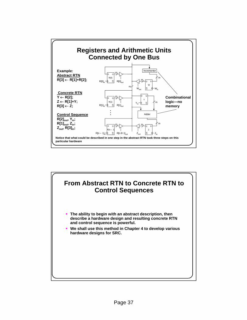
Registers and Arithmetic Units Connected by One Bus
Example:Abstract RTN
mIncrementer
D Q
Combinationallogic—no memory
Abstract RTNR[3] ← R[1]+R[2];
Concrete RTNY ← R[2];Z ← R[1]+Y;R[3] ← Z;
R[0]in
Yin
R[0]out
m
m
m
mR[0]
R[1]in R[1]out
mD Q
Q
Q
WinWout
W
DQ
Q
R[1]
D Q
Q
Y
.Control SequenceR[2]out, Yin;R[1]out, Zin;Zout, R[3]in;
Notice that what could be described in one step in the abstract RTN took three steps on this particular hardware
m
Adder
R[n – 1]in R[n Ð 1]out
mD Q
Q
m
Zout Zin
Z
DQ
Q
R[n – 1]
. .
From Abstract RTN to Concrete RTN to Control Sequences
The ability to begin with an abstract description, then describe a hardware design and resulting concrete RTN and control sequence is powerful.We shall use this method in Chapter 4 to develop various hardware designs for SRC.

Page 38
Chapter 2 Summary
Classes of computer ISAspMemory addressing modesSRC: a complete example ISARTN as a description method for ISAsRTN description of addressing modesImplementation of RTN operations with digital logic circuitsG t t b d lti lGates, strobes, and multiplexers