four high-output, slim-profile rgb tri-color led par lights … · · 2017-06-21four high-output,...
TRANSCRIPT

Four high-output, slim-profile RGB tri-color LED par lights
with included IR6 remote, power and DMX cables,
and custom carry bag
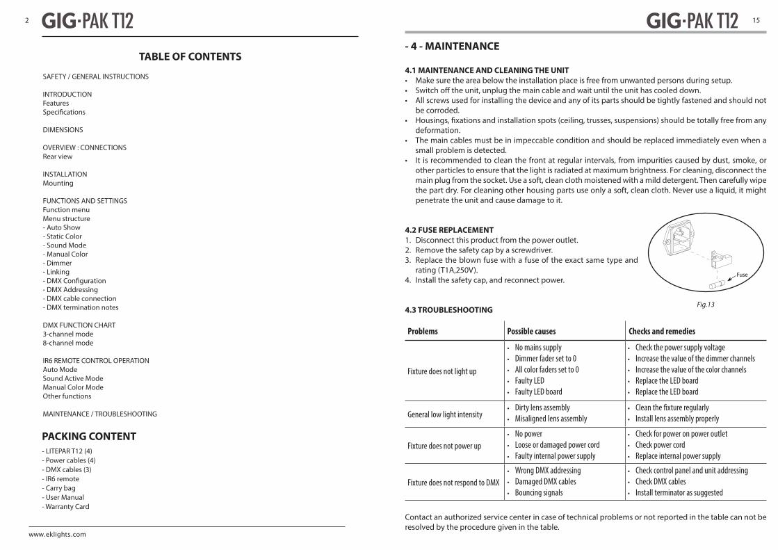
TABLE OF CONTENTS
SAFETY / GENERAL INSTRUCTIONS
INTRODUCTIONFeaturesSpeci�cations
DIMENSIONS
OVERVIEW : CONNECTIONSRear view
INSTALLATIONMounting
FUNCTIONS AND SETTINGSFunction menuMenu structure- Auto Show- Static Color- Sound Mode- Manual Color- Dimmer- Linking- DMX Con�guration- DMX Addressing- DMX cable connection- DMX termination notes
DMX FUNCTION CHART3-channel mode8-channel mode
IR6 REMOTE CONTROL OPERATIONAuto ModeSound Active ModeManual Color ModeOther functions
MAINTENANCE / TROUBLESHOOTING
- LITEPAR T12 (4)- Power cables (4)- DMX cables (3)- IR6 remote- Carry bag- User Manual- Warranty Card
PACKING CONTENT
2
- 4 - MAINTENANCE
4.1 MAINTENANCE AND CLEANING THE UNIT• Make sure the area below the installation place is free from unwanted persons during setup.
• All screws used for installing the device and any of its parts should be tightly fastened and should not be corroded.
deformation.• The main cables must be in impeccable condition and should be replaced immediately even when a
small problem is detected.• It is recommended to clean the front at regular intervals, from impurities caused by dust, smoke, or
other particles to ensure that the light is radiated at maximum brightness. For cleaning, disconnect the main plug from the socket. Use a soft, clean cloth moistened with a mild detergent. Then carefully wipe the part dry. For cleaning other housing parts use only a soft, clean cloth. Never use a liquid, it might penetrate the unit and cause damage to it.
4.2 FUSE REPLACEMENT1. Disconnect this product from the power outlet.2. Remove the safety cap by a screwdriver.3. Replace the blown fuse with a fuse of the exact same type and
rating (T1A,250V).4. Install the safety cap, and reconnect power.
4.3 TROUBLESHOOTING
Fuse
Fig.13
Problems Possible causes Checks and remedies
Fixture does not light up
• No mains supply• Dimmer fader set to 0• All color faders set to 0• Faulty LED• Faulty LED board
• Check the power supply voltage• Increase the value of the dimmer channels• Increase the value of the color channels• Replace the LED board• Replace the LED board
General low light intensity• Dirty lens assembly• Misaligned lens assembly
• • Install lens assembly properly
Fixture does not power up• No power• Loose or damaged power cord• Faulty internal power supply
• Check for power on power outlet• Check power cord• Replace internal power supply
Fixture does not respond to DMX• Wrong DMX addressing• Damaged DMX cables• Bouncing signals
• Check control panel and unit addressing• Check DMX cables• Install terminator as suggested
Contact an authorized service center in case of technical problems or not reported in the table can not be resolved by the procedure given in the table.
15
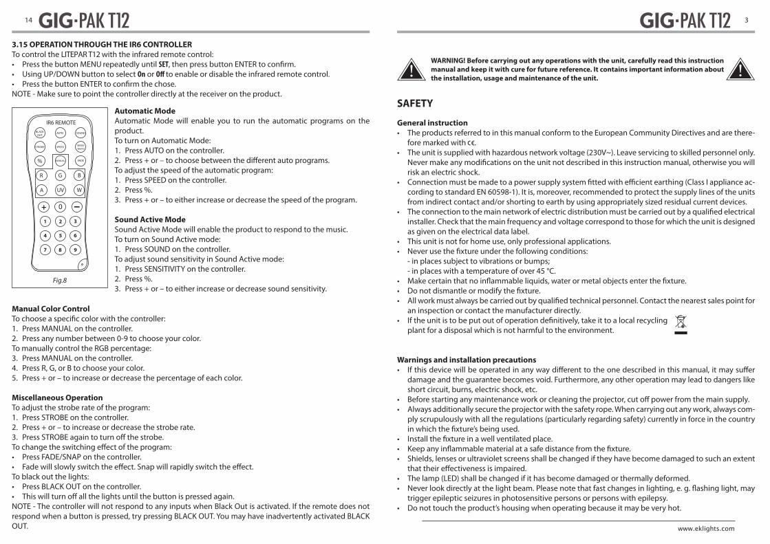
3.15 OPERATION THROUGH THE IR6 CONTROLLERTo control the LITEPAR T12 with the infrared remote control:• Press the button MENU repeatedly until SET• Using UP/DOWN button to select On or to enable or disable the infrared remote control.
NOTE - Make sure to point the controller directly at the receiver on the product.
Automatic ModeAutomatic Mode will enable you to run the automatic programs on the product.To turn on Automatic Mode:1. Press AUTO on the controller.2. To adjust the speed of the automatic program:1. Press SPEED on the controller.2. Press %.3. Press + or – to either increase or decrease the speed of the program.
Sound Active ModeSound Active Mode will enable the product to respond to the music.To turn on Sound Active mode:1. Press SOUND on the controller.To adjust sound sensitivity in Sound Active mode:1. Press SENSITIVITY on the controller.2. Press %.3. Press + or – to either increase or decrease sound sensitivity.
Manual Color Control
1. Press MANUAL on the controller.2. Press any number between 0-9 to choose your color.To manually control the RGB percentage:3. Press MANUAL on the controller.4. Press R, G, or B to choose your color.5. Press + or – to increase or decrease the percentage of each color.
Miscellaneous OperationTo adjust the strobe rate of the program:1. Press STROBE on the controller.2. Press + or – to increase or decrease the strobe rate.
• Press FADE/SNAP on the controller.
To black out the lights:• Press BLACK OUT on the controller.
NOTE - The controller will not respond to any inputs when Black Out is activated. If the remote does not respond when a button is pressed, try pressing BLACK OUT. You may have inadvertently activated BLACK OUT.
Fig.8
IR6 REMOTEBLACK
OUTAUTO
STROBE SPEED
SOUND
SENSI-TIVITY
% MANUAL FADE
R G B
+ 0
1 2 3
4 5 6
7 8 9
A UV W
14
WARNING! Before carrying out any operations with the unit, carefully read this instruction manual and keep it with cure for future reference. It contains important information about the installation, usage and maintenance of the unit.
SAFETY
General instruction• The products referred to in this manual conform to the European Community Directives and are there-
fore marked with .• The unit is supplied with hazardous network voltage (230V~). Leave servicing to skilled personnel only.
Never make risk an electric shock.
• cording to standard EN 60598-1). It is, moreover, recommended to protect the supply lines of the units from indirect contact and/or shorting to earth by using appropriately sized residual current devices.
installer. Check that the main frequency and voltage correspond to those for which the unit is designed as given on the electrical data label.
• This unit is not for home use, only professional applications.
- in places subject to vibrations or bumps;- in places with a temperature of over 45 °C.
an inspection or contact the manufacturer directly.
plant for a disposal which is not harmful to the environment.
Warnings and installation precautions
damage and the guarantee becomes void. Furthermore, any other operation may lead to dangers like short circuit, burns, electric shock, etc.
• Always additionally secure the projector with the safety rope. When carrying out any work, always com-ply scrupulously with all the regulations (particularly regarding safety) currently in force in the country
• Shields, lenses or ultraviolet screens shall be changed if they have become damaged to such an extent
• The lamp (LED) shall be changed if it has become damaged or thermally deformed.
trigger epileptic seizures in photosensitive persons or persons with epilepsy.• Do not touch the product’s housing when operating because it may be very hot.
3
INTRODUCTIONGIG-PAK T12 is a set of four high-output, slim-pro�le RGB tri-color LED par lights with included IR6 remote, power and DMX cables, and custom carry bag
FEATURES
- Extremely bright slim-pro�le RGB tri-color LED par light package- Rugged custom designed die-cast housing- USB port for optional UFI wi-� transceiver for wireless DMX control- Master/slave functionality for easy synchronized light show programming- Onboard push button control of color mixing and dimming - no controller required- Built-in sound-active and auto (stand-alone) programs- High-frequency LED modulation for �icker-free video playback- Power In and Out connections for linking mutliple units- Easily �ts inside standard truss dimensions for dramatic uplighting e�ects- All required power and DMX cables included- IR6 multifunction infrared remote control included
SPECIFICATIONS (LITEPAR T12 FIXTURE)
Light Source: 12 x 3W Tri-color LED Beam Angle: 15° Field Angle: 30° Colors: RGB color mixing Output: 428 LUX @ 5 meters Strobe: 0 - 30 Hz PWM Frequency: 600 Hz, �icker-free Dimming: 0-100% dimming, 4 selectable dimming curves Control modes: DMX, Auto, Sound-Active, Koala wireless DMX (with optional UFI transceiver), IR6 infrared controller DMX Channels: 3 / 8 Built-in Programs: Yes Menu: 4-digit LED display Mains: 100 - 240 VAC, 50/60 Hz (auto-ranging) Power: 38W Power Linking: Up to 8 units Power connections: IEC power In/Out Data connections: 3-pin XLR In/Out for DMX Housing: Die-cast aluminium Finish: Matte Black IP rating: IP20 Dimensions: 252 x 227 x 84 mm Weight: 1.8 KG
4
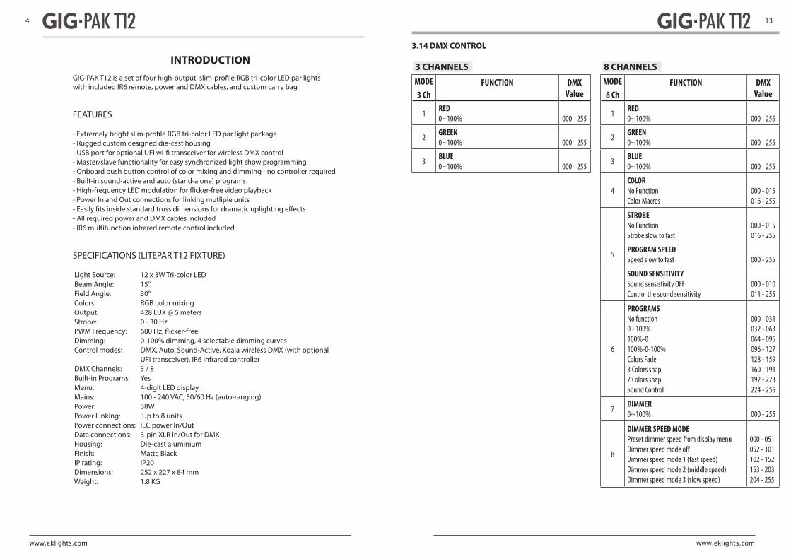
3.14 DMX CONTROL
3 CHANNELS
MODE FUNCTION DMXValue3 Ch
1RED
552 - 000%001~0
2GREEN
552 - 000%001~0
3BLUE
552 - 000%001~0
8 CHANNELS
MODE FUNCTION DMXValue8 Ch
1RED
552 - 000%001~0
2GREEN
552 - 000%001~0
3BLUE
552 - 000%001~0
4COLORNo FunctionColor Macros
000 - 015016 - 255
5
STROBENo FunctionStrobe slow to fast
000 - 015016 - 255
PROGRAM SPEEDSpeed slow to fast 000 - 255
SOUND SENSITIVITYSound sensistivity OFFControl the sound sensitivity
000 - 010011 - 255
6
PROGRAMSNo function0 - 100%100%-0100%-0-100%Colors Fade3 Colors snap7 Colors snapSound Control
000 - 031032 - 063064 - 095096 - 127128 - 159160 - 191192 - 223224 - 255
7DIMMER
552 - 000%001~0
8
DIMMER SPEED MODEPreset dimmer speed from display menu
Dimmer speed mode 1 (fast speed)Dimmer speed mode 2 (middle speed)Dimmer speed mode 3 (slow speed)
000 - 051052 - 101102 - 152153 - 203204 - 255
13

Fig.6
Fig.7
3.12 CONNECTION OF THE DMX LINEDMX connection employs standard XLR connectors. Use shielded pair-twisted cables with 120Ω imped-ance and low capacity.The following diagram shows the connection mode:
ATTENTIONThe screened parts of the cable (sleeve) must never be connected to the system’s earth, as this would
For those connections the use of balanced microphone cable is not recommended because it cannot transmit control DMX data reliably.
• Connect the DMX output to the DMX input of the following unit. Connect again the output to the input of the following unit until all the units are connected in chain.
• When the signal cable has to run longer distance is recommended to insert a DMX termination on the last unit.
3.13 CONSTRUCTION OF THE DMX TERMINATION
es the end of the line: under certain conditions and with certain cable lengths, this could cause them to cancel the original signals.The termination is prepared by soldering a 120Ω 1/4 W resistor between pins 2 and 3 of the 3-pin male XLR
DMX - OUTPUTXLR socket
DMX - INPUTXLR plug
Pin1 : GND - ShieldPin2 : - NegativePin3 : + Positive
Example:3 pin XLR connector
12
Technical drawingFig.1
184
226 220
SPECIFICATIONS (GIG-PAK T12 PACKAGE)
LITEPAR T12: 4Power cables: 4DMX cables: 3IR6 remote: 1Carry bag: 1Dimensions: 375 x 270 x 300 mmWeight: 8.9 KG
INTRODUCTION (Cont’d)
DIMENSIONS
5

1.3 OPERATING ELEMENTS AND CONNECTIONS
Fig.2 - Rear panel
1. MOUNTING BRACKET2. LOCKING KNOB for the mounting bracket3. DMX IN (3-pole XLR):
1 = ground, 2 = DMX -, 3 = DMX +4. DMX OUT (3-pole XLR):
1= ground, 2 = DMX -, 3 = DMX +5. POWER IN mains plug for connection to a
socket (100-240V~/50-60Hz) via the supplied mains cable. The support for the mains fuse is located near the mains plug. Only replace a blown fuse by one of the same type (T1A,250V).
6. CONTROL PANEL with display and 4 button used to access the control panel functions and manage them.
7. Universal Serial Bus (USB)8. POWER OUT: connect to supply power to the
next unit.9. SAFETY EYE to attach safety cable
1
2
63 4 9
5 7 8
6
Number ofDMX channels
Start address (example)
DMX Address occupied
Next possible start address for unit No. 1
Next possible start address for unit No. 2
Next possible start address for unit No. 3
3 33 33-35 36 39 42
8 33 33-40 41 49 57
DMX Address: 57DMX Address: 41DMX Address: 33 DMX Address: 49
............
DMX512 Controller
The tables on page 13 indicate the operating mode and DMX value. The LITEPAR T12 is equipped with 3-pole XLR connections.
3.11 DMX ADDRESSING
channel, adjust the start address 33 on the LITEPAR T12.
An example with the start address 33 is shown below:
LITEPAR T12
11

• Press the MENU button to go back or to meet the waiting time to exit the setup menu.
3.6 SOUND MODEIn music mode, via its integrated microphone, the unit can be controlled by music with a clear rhythm in the bass range. If the music control should not work optimally, increase the volume or reduce the distance
• Press the button MENU so many times until the display shows Snd. • Using UP/DOWN button, select one of the modes Snd1 or Snd2.• • You can set the microphone sensitivity pressing the button MENU so many times until the display show
Sens • Using the button UP/DOWN, select the desired value sensitivity (slow-fast) u0 - u100.
3.7 MANUAL COLORThis mode allows to combine the colors red, green and blue (r, g, b).• Press the button MENU so many times until the display shows U-- , then press the button ENTER.• Select the color r, g, b through the buttons UP/DOWN.
• Using UP/DOWN button, select the desired color value 000 - 255.• Press ENTER button to continue to the next color.• Continue until the desired mix is obtained.• Press the MENU button to go back or to meet the waiting time to exit the setup menu.
3.8 DIMMER
shows dIM• Press the button UP/DOWN to select OFF - dIM1 - dIM2 - dIM3.• Press ENTER button to store.• Press the MENU button to go back or to meet the waiting time to exit the setup menu.
3.9 LINKING
master unit. Use standard DMX cables to daisy chain your units together via the DMX connector on the
are connected in a chain.
3.10 DMX CONFIGURATION
3CH - 8CH), then press the button ENTER.• Press the button UP/DOWN to select the desider value (001 - 512), then press the button ENTER to con-
• Press the MENU button to go back or to meet the waiting time to exit the setup menu.
LITEPAR T12
10
- 2 - INSTALLATION
2.1 MOUNTINGLITEPAR T12 may be set up on a solid and even surface. The unit can also be mounted upside down to
ity and be able to support a weight of 10 times of the unit’s weight.When carrying out any installation, always comply scrupulously with all the regulations (particularly re-
• Install the projector at a suitable location by means of the mounting bracket (1).• Always additionally secure the projector with the safety rope from falling down. For this purpose, fas-
ten the safety rope at a suitable position so that the maximum fall of the projector will be 20 cm.• Adjust the projector and use the knob (2) to slightly release or tighten the locking mechanism of the
bracket if is necessary.
Fig.3
2
1
7

Fig.4 - Functions of the buttons
- 3 - FUNCTIONS AND SETTINGS
3.1 OPERATIONConnect the supplied main cable to a socket (100-240 VAC-50/60 Hz). Then the unit is ready for operation and can be operated via a DMX controller or it independently performs its show program in succession.
3.2 BASICAccess control panel functions using the four panel buttons located directly underneath the LED Display
MENU UP DOWN ENTER
Used to access the menu or to return a previous menu option
Increases the numeric value when in a function
Decreases the numeric value when in a function
Used to select and store the current
value or option within a menu
MENU UP DOWN ENTER
8
3.3 MENU STRUCTURE
3.4 AUTO SHOW
• Press the button MENU so many times until shows P-- , then press the button ENTER.• Using UP/DOWN button, select one of the programs P1 - P4.
• Press the button MENU until S-- appears on the display.• Use the button UP/DOWN to select the auto programs speed S001 - S100 (slow-fast).• Press the button ENTER save the setting.
3.5 STATIC COLOR
• Press the button MENU so many times until shows C-- , then press the button ENTER.• Using UP/DOWN button, select one of the programs C1 - C7.
MENU
1 DMX Personality and Starting Address
3 CH d1 - d512 Selects DMX personality and DMX starting value8 CH d1 - d512
2 Static Colors C-- sroloc citats 7 fo 1 stceleS7C - 1C
3 Auto Programs P-- smargorp otua 4 fo 1 stceleS4P - 1P
4 Programs Speed S-- )tsaf ot wols( deeps margorp otua steS001S - 1S
5 Sound Active Snd edom evitcA dnuoS stceleS2dnS - 1dnS
6 Sound Sensitivity SenS )hgih ot wol( ytivitisnes dnuos steS001u - 0u
7 Custom Color Mixing U-- )%001-0( deR552r - 0r
)%001-0( neerG552g - 0g
)%001-0( eulB552b - 0b
8 Dimmer dIM D :FFOFFO
tsaf deeps remmiD :1MID1MId
elddim deeps remmiD :2MID2MId
wols deeps remmiD :3MID3MId
9 Infrared SET ON
OFF
9