foundations of process-aware information...
TRANSCRIPT

Foundations ofProcess-Aware Information Systems
by
Nicholas Charles Russell BSc MInfTech
a dissertation submitted for the degreeIF49 Doctor of Philosophy
Principal Supervisor: Assoc. Prof. Arthur ter Hofstede
Associate Supervisors: Dr David Edmond
Prof. Wil van der Aalst
Faculty of Information TechnologyQueensland University of Technology
Brisbane, Australia
December 2007

This page is intentionally blank

Certificate of Acceptance

This page is intentionally blank

Further, longer, higher, olderGrant McLennan (1958–2006)

This page is intentionally blank

Keywords
Process-aware information systems, PAIS, Business process management, Work-flow management, Business process modelling, Workflow patterns, Coloured Petrinets, Yet Another Workflow Language (YAWL), newYAWL
i

This page is intentionally blank
ii

Abstract
Over the past decade, the ubiquity of business processes and their need for ongo-ing management in the same manner as other corporate assets has been recognizedthrough the establishment of a dedicated research area: Business Process Man-agement (or BPM). There are a wide range of potential software technologies onwhich a BPM offering can be founded. Although there is significant variationbetween these alternatives, they all share one common factor – their executionoccurs on the basis of a business process model – and consequently, this field oftechnologies can be termed Process-Aware Information Systems (or PAIS).
This thesis develops a conceptual foundation for PAIS based on the results of adetailed examination of contemporary offerings including workflow and case han-dling systems, business process modelling languages and web service compositionlanguages. This foundation is based on 126 patterns that identify recurrent coreconstructs in the control-flow, data and resource perspectives of PAIS. Thesepatterns have been used to evaluate some of the leading systems and businessprocess modelling languages. It also proposes a generic graphical language fordefining exception handling strategies that span these perspectives.
On the basis of these insights, a comprehensive reference language – newYAWL– is developed for business process modelling and enactment. This language isformally defined and an abstract syntax and operational semantics are providedfor it. An assessment of its capabilities is provided through a comprehensivepatterns-based analysis which allows direct comparison of its functionality withother PAIS. newYAWL serves as a reference language and many of the ideasembodied within it are also applicable to existing languages and systems. Theultimate goal of both the patterns and newYAWL is to improve the support andapplicability of PAIS.
iii

This page is intentionally blank
iv

Contents
Keywords i
Abstract iii
Contents v
List of Figures viii
Statement of Original Authorship xv
Acknowledgements xvii
1 Introduction 1
1.1 Problem area . . . . . . . . . . . . . . . . . . . . . . . . . . . . . 1
1.2 Problem statement . . . . . . . . . . . . . . . . . . . . . . . . . . 10
1.3 Solution criteria . . . . . . . . . . . . . . . . . . . . . . . . . . . . 11
1.4 Approach . . . . . . . . . . . . . . . . . . . . . . . . . . . . . . . 12
1.5 Publications . . . . . . . . . . . . . . . . . . . . . . . . . . . . . . 13
1.6 Related work . . . . . . . . . . . . . . . . . . . . . . . . . . . . . 15
1.7 Outline of thesis . . . . . . . . . . . . . . . . . . . . . . . . . . . . 17
I Conceptual Foundations 19
2 Control-Flow Perspective 26
2.1 Context assumptions . . . . . . . . . . . . . . . . . . . . . . . . . 27
2.2 An overview of coloured Petri nets . . . . . . . . . . . . . . . . . 28
2.3 A review of the original control-flow patterns . . . . . . . . . . . . 29
2.4 New control-flow patterns . . . . . . . . . . . . . . . . . . . . . . 68
2.5 Survey of control-flow pattern support . . . . . . . . . . . . . . . 104
2.6 Related work . . . . . . . . . . . . . . . . . . . . . . . . . . . . . 107
2.7 Summary . . . . . . . . . . . . . . . . . . . . . . . . . . . . . . . 109
v
3 Data Perspective 110
3.1 High-level process diagrams . . . . . . . . . . . . . . . . . . . . . 111
3.2 Data visibility patterns . . . . . . . . . . . . . . . . . . . . . . . . 112
3.3 Data interaction patterns . . . . . . . . . . . . . . . . . . . . . . . 125
3.4 Data transfer patterns . . . . . . . . . . . . . . . . . . . . . . . . 147
3.5 Data-based routing patterns . . . . . . . . . . . . . . . . . . . . . 154
3.6 Survey of data patterns support . . . . . . . . . . . . . . . . . . . 164
3.7 Related work . . . . . . . . . . . . . . . . . . . . . . . . . . . . . 168
3.8 Summary . . . . . . . . . . . . . . . . . . . . . . . . . . . . . . . 169
4 Resource Perspective 170
4.1 Organizational modelling . . . . . . . . . . . . . . . . . . . . . . . 171
4.2 Work distribution to resources . . . . . . . . . . . . . . . . . . . . 174
4.3 Creation patterns . . . . . . . . . . . . . . . . . . . . . . . . . . . 175
4.4 Push patterns . . . . . . . . . . . . . . . . . . . . . . . . . . . . . 189
4.5 Pull patterns . . . . . . . . . . . . . . . . . . . . . . . . . . . . . 198
4.6 Detour patterns . . . . . . . . . . . . . . . . . . . . . . . . . . . . 204
4.7 Auto-start patterns . . . . . . . . . . . . . . . . . . . . . . . . . . 213
4.8 Visibility patterns . . . . . . . . . . . . . . . . . . . . . . . . . . . 217
4.9 Multiple resource patterns . . . . . . . . . . . . . . . . . . . . . . 218
4.10 Survey of resource pattern support . . . . . . . . . . . . . . . . . 221
4.11 Related work . . . . . . . . . . . . . . . . . . . . . . . . . . . . . 228
4.12 Summary . . . . . . . . . . . . . . . . . . . . . . . . . . . . . . . 229
5 Exception Handling Perspective 230
5.1 A framework for exception handling . . . . . . . . . . . . . . . . . 231
5.2 Survey of exception handling capabilities . . . . . . . . . . . . . . 238
5.3 Considerations for a process exception language . . . . . . . . . . 240
5.4 Related work . . . . . . . . . . . . . . . . . . . . . . . . . . . . . 243
5.5 Summary . . . . . . . . . . . . . . . . . . . . . . . . . . . . . . . 244
II Language Design 247
6 An Introduction to newYAWL 250
6.1 Control-flow perspective . . . . . . . . . . . . . . . . . . . . . . . 250
6.2 Data perspective . . . . . . . . . . . . . . . . . . . . . . . . . . . 259
6.3 Resource perspective . . . . . . . . . . . . . . . . . . . . . . . . . 263
6.4 Exception handling perspective . . . . . . . . . . . . . . . . . . . 269
6.5 Summary . . . . . . . . . . . . . . . . . . . . . . . . . . . . . . . 270

7 Syntax 271
7.1 Abstract syntax for newYAWL . . . . . . . . . . . . . . . . . . . 272
7.2 From complete to core newYAWL . . . . . . . . . . . . . . . . . . 279
7.3 Semantic model initialization . . . . . . . . . . . . . . . . . . . . 296
7.4 Summary . . . . . . . . . . . . . . . . . . . . . . . . . . . . . . . 307
8 Semantics 308
8.1 Overview . . . . . . . . . . . . . . . . . . . . . . . . . . . . . . . . 308
8.2 Core concepts . . . . . . . . . . . . . . . . . . . . . . . . . . . . . 311
8.3 Control-flow & data handling . . . . . . . . . . . . . . . . . . . . 314
8.4 Work distribution . . . . . . . . . . . . . . . . . . . . . . . . . . . 326
8.5 Summary . . . . . . . . . . . . . . . . . . . . . . . . . . . . . . . 352
9 Pattern Support in newYAWL 353
9.1 Control-flow perspective . . . . . . . . . . . . . . . . . . . . . . . 353
9.2 Data perspective . . . . . . . . . . . . . . . . . . . . . . . . . . . 354
9.3 Resource perspective . . . . . . . . . . . . . . . . . . . . . . . . . 355
9.4 Exception handling perspective . . . . . . . . . . . . . . . . . . . 356
9.5 Summary . . . . . . . . . . . . . . . . . . . . . . . . . . . . . . . 356
10 Epilogue 358
A Patterns Realization in newYAWL 362
A.1 Control-flow patterns . . . . . . . . . . . . . . . . . . . . . . . . . 362
A.2 Data patterns . . . . . . . . . . . . . . . . . . . . . . . . . . . . . 367
A.3 Resource patterns . . . . . . . . . . . . . . . . . . . . . . . . . . . 373
B Mathematical Notations 377
Bibliography 378

List of Figures
1.1 History of office automation and workflow management systems(from [Mue04]) . . . . . . . . . . . . . . . . . . . . . . . . . . . . 5
1.2 Workflow reference model (from [Wor95]) . . . . . . . . . . . . . . 8
1.3 PAIS types and associated development tools (from [DAH05a]) . . 9
2.1 Example of a CP-net process model . . . . . . . . . . . . . . . . . 28
2.2 Sequence pattern . . . . . . . . . . . . . . . . . . . . . . . . . . . 32
2.3 Parallel split pattern . . . . . . . . . . . . . . . . . . . . . . . . . 34
2.4 Synchronization pattern . . . . . . . . . . . . . . . . . . . . . . . 35
2.5 Exclusive choice pattern . . . . . . . . . . . . . . . . . . . . . . . 36
2.6 Simple merge pattern . . . . . . . . . . . . . . . . . . . . . . . . . 38
2.7 Multi-choice pattern . . . . . . . . . . . . . . . . . . . . . . . . . 40
2.8 Structured synchronizing merge pattern . . . . . . . . . . . . . . . 43
2.9 Local synchronizing merge pattern . . . . . . . . . . . . . . . . . 43
2.10 Multi-merge pattern . . . . . . . . . . . . . . . . . . . . . . . . . 45
2.11 Structured discriminator pattern . . . . . . . . . . . . . . . . . . 46
2.12 Blocking discriminator pattern . . . . . . . . . . . . . . . . . . . . 47
2.13 Cancelling discriminator pattern . . . . . . . . . . . . . . . . . . . 47
2.14 Arbitrary cycles pattern . . . . . . . . . . . . . . . . . . . . . . . 49
2.15 Multiple instances without synchronization (variant 1) . . . . . . 52
2.16 Multiple instances without synchronization (variant 2) . . . . . . 53
2.17 Multiple instances with a priori design-time knowledge (variant 1) 54
2.18 Multiple instances with a priori design-time knowledge (variant 2) 54
2.19 Multiple instances with a priori runtime knowledge (variant 1) . . 56
2.20 Multiple instances with a priori runtime knowledge (variant 2) . . 56
2.21 Multiple instances without a priori runtime knowledge (variant 1) 57
2.22 Multiple instances without a priori runtime knowledge (variant 2) 58
2.23 Deferred choice pattern . . . . . . . . . . . . . . . . . . . . . . . . 59
2.24 Interleaved parallel routing pattern . . . . . . . . . . . . . . . . . 61
2.25 Milestone pattern . . . . . . . . . . . . . . . . . . . . . . . . . . . 62
viii

2.26 Cancel task pattern (variant 1) . . . . . . . . . . . . . . . . . . . 64
2.27 Cancel task pattern (variant 2) . . . . . . . . . . . . . . . . . . . 64
2.28 Cancel task pattern with guaranteed termination . . . . . . . . . 64
2.29 Cancel case pattern (variant 1) . . . . . . . . . . . . . . . . . . . 66
2.30 Cancel case pattern (variant 2) . . . . . . . . . . . . . . . . . . . 66
2.31 Cancel region implementation . . . . . . . . . . . . . . . . . . . . 67
2.32 Structured loop pattern (while variant) . . . . . . . . . . . . . . . 69
2.33 Structured loop pattern (repeat variant) . . . . . . . . . . . . . . 69
2.34 Recursion pattern . . . . . . . . . . . . . . . . . . . . . . . . . . . 70
2.35 Recursion implementation . . . . . . . . . . . . . . . . . . . . . . 71
2.36 Transient trigger pattern (safe variant) . . . . . . . . . . . . . . . 72
2.37 Transient trigger pattern (unsafe variant) . . . . . . . . . . . . . . 73
2.38 Persistent trigger pattern . . . . . . . . . . . . . . . . . . . . . . 74
2.39 Persistent trigger pattern (new execution thread variant) . . . . . 74
2.40 Cancel region implementation . . . . . . . . . . . . . . . . . . . . 75
2.41 Cancel multiple instance task pattern (sequential initiation) . . . 77
2.42 Cancel multiple instance task pattern (concurrent initiation) . . . 77
2.43 Complete multiple instance task pattern (sequential initiation) . . 79
2.44 Complete multiple instance task pattern (concurrent initiation) . 79
2.45 Blocking discriminator pattern . . . . . . . . . . . . . . . . . . . . 81
2.46 Cancelling discriminator pattern . . . . . . . . . . . . . . . . . . . 82
2.47 Cancelling discriminator pattern in BPMN and UML 2.0 ADs . . 83
2.48 Process structure considerations for cancelling discriminator . . . 84
2.49 Structured partial join pattern . . . . . . . . . . . . . . . . . . . . 85
2.50 Blocking partial join pattern . . . . . . . . . . . . . . . . . . . . . 87
2.51 Cancelling partial join pattern . . . . . . . . . . . . . . . . . . . . 88
2.52 Generalized AND-join pattern . . . . . . . . . . . . . . . . . . . . 90
2.53 Static partial join implementation for multiple instances . . . . . 91
2.54 Cancelling partial join implementation for multiple instances . . . 93
2.55 Dynamic partial join implementation for multiple instances . . . . 94
2.56 Local synchronizing merge pattern . . . . . . . . . . . . . . . . . 96
2.57 General synchronizing merge pattern . . . . . . . . . . . . . . . . 97
2.58 Critical section pattern . . . . . . . . . . . . . . . . . . . . . . . . 99
2.59 Interleaved routing pattern . . . . . . . . . . . . . . . . . . . . . . 100
2.60 Thread merge pattern . . . . . . . . . . . . . . . . . . . . . . . . 101
2.61 Thread split pattern . . . . . . . . . . . . . . . . . . . . . . . . . 102
3.1 Example of a high-level process diagram . . . . . . . . . . . . . . 111
3.2 Task level data visibility . . . . . . . . . . . . . . . . . . . . . . . 113
3.3 Block level data visibility . . . . . . . . . . . . . . . . . . . . . . . 114
3.4 Scope level data visibility . . . . . . . . . . . . . . . . . . . . . . . 116
3.5 Alternative implementations of multiple instance tasks . . . . . . 117
3.6 Case level data visibility . . . . . . . . . . . . . . . . . . . . . . . 119
3.7 Folder data visibility . . . . . . . . . . . . . . . . . . . . . . . . . 121
3.8 Global data visibility . . . . . . . . . . . . . . . . . . . . . . . . . 123
3.9 Environment data visibility . . . . . . . . . . . . . . . . . . . . . 124
3.10 Approaches to data interaction between tasks . . . . . . . . . . . 126
3.11 Approaches to data interaction from block tasks to correspondingsubprocesses . . . . . . . . . . . . . . . . . . . . . . . . . . . . . . 129
3.12 Data interaction approaches for multiple instance tasks . . . . . . 132
3.13 Data interaction between cases . . . . . . . . . . . . . . . . . . . 134
3.14 Data interaction between tasks and the operating environment . . 136
3.15 Data interaction between cases and the operating environment . . 141
3.16 Data interaction between a process environment and the operatingenvironment . . . . . . . . . . . . . . . . . . . . . . . . . . . . . . 144
3.17 Data transfer by value . . . . . . . . . . . . . . . . . . . . . . . . 148
3.18 Data transfer – copy in/copy out . . . . . . . . . . . . . . . . . . 150
3.19 Data transfer by reference – unlocked . . . . . . . . . . . . . . . . 151
3.20 Data transformation – input and output . . . . . . . . . . . . . . 153
3.21 Task precondition – data existence . . . . . . . . . . . . . . . . . 155
3.22 Task postcondition – data existence . . . . . . . . . . . . . . . . . 158
3.23 Event-based task trigger . . . . . . . . . . . . . . . . . . . . . . . 160
3.24 Data-based task trigger . . . . . . . . . . . . . . . . . . . . . . . . 162
3.25 Data-based routing . . . . . . . . . . . . . . . . . . . . . . . . . . 163
4.1 Organizational meta-model . . . . . . . . . . . . . . . . . . . . . . 173
4.2 Basic work item lifecycle . . . . . . . . . . . . . . . . . . . . . . . 174
4.3 Creation patterns . . . . . . . . . . . . . . . . . . . . . . . . . . . 176
4.4 Capability-based distribution . . . . . . . . . . . . . . . . . . . . 185
4.5 Push patterns . . . . . . . . . . . . . . . . . . . . . . . . . . . . . 190
4.6 Pull patterns . . . . . . . . . . . . . . . . . . . . . . . . . . . . . 199
4.7 Detour patterns . . . . . . . . . . . . . . . . . . . . . . . . . . . . 205
4.8 Auto-start patterns . . . . . . . . . . . . . . . . . . . . . . . . . . 214
5.1 Options for handling work items . . . . . . . . . . . . . . . . . . . 234
5.2 Exception handling primitives . . . . . . . . . . . . . . . . . . . . 240
5.3 Exception handling strategies for a process . . . . . . . . . . . . . 241

5.4 Order despatch process . . . . . . . . . . . . . . . . . . . . . . . . 242
5.5 Exception handling strategies – order despatch process . . . . . . 242
6.1 newYAWL symbology . . . . . . . . . . . . . . . . . . . . . . . . 251
6.2 Example of thread split and merge usage . . . . . . . . . . . . . . 253
6.3 Example of the partial join: defect notice is a 1-out-of-3 join . . . 254
6.4 Example of a repeat loop . . . . . . . . . . . . . . . . . . . . . . . 254
6.5 Example of a while loop . . . . . . . . . . . . . . . . . . . . . . . 255
6.6 Example of a combination loop . . . . . . . . . . . . . . . . . . . 256
6.7 Example of persistent trigger usage . . . . . . . . . . . . . . . . . 256
6.8 Example of transient trigger usage . . . . . . . . . . . . . . . . . . 257
6.9 Example of completion region usage: timeout forces review recordsto complete . . . . . . . . . . . . . . . . . . . . . . . . . . . . . . 258
6.10 Example of completion region usage using transient triggers . . . 258
6.11 Example of dynamic multiple instance task disablement . . . . . . 259
6.12 Multiple instance input parameter handling . . . . . . . . . . . . 261
6.13 Multiple instance output parameter handling . . . . . . . . . . . . 262
6.14 Work item interaction strategies in newYAWL . . . . . . . . . . . 266
7.1 Preparing a newYAWL process model for enactment . . . . . . . 271
7.2 Persistent and transient trigger transformation . . . . . . . . . . . 281
7.3 Transformation of pre-test and post-test loops . . . . . . . . . . . 284
7.4 Transformation of thread merge construct . . . . . . . . . . . . . 288
7.5 Transformation of thread split construct . . . . . . . . . . . . . . 289
7.6 Transformation of partial join construct . . . . . . . . . . . . . . . 290
7.7 Inserting an implicit condition between directly linked tasks . . . 295
7.8 Reset net transformations for newYAWL constructs . . . . . . . . 298
8.1 Overview of the process execution lifecycle . . . . . . . . . . . . . 310
8.2 Subprocess identification . . . . . . . . . . . . . . . . . . . . . . . 312
8.3 Start case process . . . . . . . . . . . . . . . . . . . . . . . . . . . 316
8.4 End case process . . . . . . . . . . . . . . . . . . . . . . . . . . . 317
8.5 Enter work item process . . . . . . . . . . . . . . . . . . . . . . . 318
8.6 Start work item process . . . . . . . . . . . . . . . . . . . . . . . 321
8.7 Complete work item instance and terminate block process . . . . 322
8.8 Exit work item process . . . . . . . . . . . . . . . . . . . . . . . . 323
8.9 Add work item process . . . . . . . . . . . . . . . . . . . . . . . . 325
8.10 Data interaction between newYAWL and the operating environment326
8.11 Top level view of the main work distribution process . . . . . . . 327

8.12 Work item distribution process (top half) . . . . . . . . . . . . . . 330
8.13 Work item distribution process (bottom half) . . . . . . . . . . . 331
8.14 Work list handler process . . . . . . . . . . . . . . . . . . . . . . . 332
8.15 Interrupt handling process . . . . . . . . . . . . . . . . . . . . . . 333
8.16 Management intervention process . . . . . . . . . . . . . . . . . . 334
8.17 Work item routing activity . . . . . . . . . . . . . . . . . . . . . . 335
8.18 Process distribution failure activity . . . . . . . . . . . . . . . . . 336
8.19 Route offers activity . . . . . . . . . . . . . . . . . . . . . . . . . 336
8.20 Route allocation activity . . . . . . . . . . . . . . . . . . . . . . . 337
8.21 Route immediate start activity . . . . . . . . . . . . . . . . . . . 337
8.22 Manual distribution activity . . . . . . . . . . . . . . . . . . . . . 337
8.23 Route manual offers activity . . . . . . . . . . . . . . . . . . . . . 338
8.24 Route manual allocation activity . . . . . . . . . . . . . . . . . . 338
8.25 Process manual immediate start activity . . . . . . . . . . . . . . 338
8.26 Autonomous initiation activity . . . . . . . . . . . . . . . . . . . . 339
8.27 Autonomous completion activity . . . . . . . . . . . . . . . . . . . 339
8.28 Process selection request activity . . . . . . . . . . . . . . . . . . 339
8.29 Reject offer activity . . . . . . . . . . . . . . . . . . . . . . . . . . 340
8.30 Process start request activity . . . . . . . . . . . . . . . . . . . . 340
8.31 Suspension resumption activity . . . . . . . . . . . . . . . . . . . 340
8.32 Process completion activity . . . . . . . . . . . . . . . . . . . . . 341
8.33 Route delegation activity . . . . . . . . . . . . . . . . . . . . . . . 341
8.34 Process deallocation activity . . . . . . . . . . . . . . . . . . . . . 341
8.35 State oriented reallocation activity . . . . . . . . . . . . . . . . . 342
8.36 Route reoffers activity . . . . . . . . . . . . . . . . . . . . . . . . 342
8.37 Route reallocation activity . . . . . . . . . . . . . . . . . . . . . . 343
8.38 Reject reoffer activity . . . . . . . . . . . . . . . . . . . . . . . . . 343
8.39 Reject reallocation activity . . . . . . . . . . . . . . . . . . . . . . 344
8.40 Select activity . . . . . . . . . . . . . . . . . . . . . . . . . . . . . 344
8.41 Allocate activity . . . . . . . . . . . . . . . . . . . . . . . . . . . 345
8.42 Start activity . . . . . . . . . . . . . . . . . . . . . . . . . . . . . 345
8.43 Immediate start activity . . . . . . . . . . . . . . . . . . . . . . . 345
8.44 Halt instance activity . . . . . . . . . . . . . . . . . . . . . . . . . 346
8.45 Complete activity . . . . . . . . . . . . . . . . . . . . . . . . . . . 346
8.46 Suspend activity . . . . . . . . . . . . . . . . . . . . . . . . . . . 346
8.47 Skip activity . . . . . . . . . . . . . . . . . . . . . . . . . . . . . . 347
8.48 Delegate activity . . . . . . . . . . . . . . . . . . . . . . . . . . . 347
8.49 Abort activity . . . . . . . . . . . . . . . . . . . . . . . . . . . . . 347

8.50 Stateful reallocate activity . . . . . . . . . . . . . . . . . . . . . . 348
8.51 Stateless reallocate activity . . . . . . . . . . . . . . . . . . . . . . 348
8.52 Manipulate worklist activity . . . . . . . . . . . . . . . . . . . . . 349
8.53 Logonandoff activity . . . . . . . . . . . . . . . . . . . . . . . . . 349
8.54 Cancel work item process . . . . . . . . . . . . . . . . . . . . . . . 350
8.55 Complete work item process . . . . . . . . . . . . . . . . . . . . . 351
8.56 Fail work item process . . . . . . . . . . . . . . . . . . . . . . . . 352

This page is intentionally blank
xiv

Statement of Original Authorship
The work contained in this thesis has not been previously submitted to meetrequirements for an award at this or any other higher education institution. Tothe best of my knowledge and belief, the thesis contains no material previouslypublished or written by another person except where due reference is made.
Signed:
Date:
xv

This page is intentionally blank
xvi

Acknowledgements
The writing of this thesis has truly been a momentous journey and I am privilegedto have had a world-class supervision team to guide my efforts along the way.My sincere thanks go to my principal supervisor, Arthur ter Hofstede, who hasprovided unstinting advice, encouragement and wisdom throughout my studies.I’d also like to thank my associate supervisors: David Edmond who has giveninsightful critique and suggestions that have helped shape this work, and Wil vander Aalst who has provided the inspiration to take this research far beyond anyof my original expectations.
I would like to acknowledge the contribution of the Australian Research Coun-cil and Queensland University of Technology who funded the early parts of thisresearch. Without this support, it is unlikely that the research effort would havecommenced. I am also grateful to Eindhoven University of Technology who, dur-ing the course of my studies, have invited me to visit on three occasions to conductcollaborative research with various members of the Information Systems Groupand have provided financial support for these activities.
A work of this scale is never undertaken alone and I am indebted to my familyfor their enormous contribution and support during this period. Special thanksgo to my mother and father who have always recognized the value of educationand the opportunities it brings and whose encouragement has brought me to thispoint. I’d also like to thank my close friends, Gai and John, whose companionshipand humour have kept my spirits buoyed during my studies. Most of all, I wouldlike to express my deepest appreciation to my wife Carol and son Hugo for theiroptimism, enthusiasm and love throughout this journey. I couldn’t have done itwithout you!
xvii

This page is intentionally blank
xviii

Chapter 1. Introduction
Chapter 1
Introduction
At the heart of most successful organizations is the drive to improve efficiency.One of the keys to meeting this objective is understanding what the organiza-tion does and how it could do it better. The notion of the business processhas been a key tool in gaining this understanding and in recent years it has un-derpinned popular approaches to business improvement such as Business ProcessRe-engineering [HC93, Dav93] and Business Process Improvement [Har91]. Morerecently, the ubiquity of business processes and their need for ongoing manage-ment in the same manner as other corporate assets has been recognized throughthe establishment of a dedicated research area: Business Process Management(or BPM).
Business Process Management can be defined as “supporting business pro-cesses using methods, techniques, and software to design, enact, control, andanalyze operational processes involving humans, organizations, applications, doc-uments and other sources of information” [AHW03]. This definition sets a widescope for the area and serves to illustrate the broad range of factors which arerelevant to the definition and conduct of business operations. One of the mostsignificant considerations in deploying effective BPM solutions is in selecting andutilizing an appropriate enactment technology. As the definition for BPM indi-cates, there are a wide range of potential software technologies on which a BPMoffering can be founded. However, although there is significant variation betweenthese alternatives, they all share one common factor – their execution occurs onthe basis of a business process model – and consequently, this field of technologiescan be termed Process-Aware Information Systems (or PAIS).
This thesis aims to provide a conceptual foundation for PAIS and to use thisfoundation as the basis for a general reference language which describes the wayin which business process models should be captured and enacted.
1.1 Problem area
There are a number of distinct areas that inform the research topic. The followingsections provide a brief overview of the most significant of these.
PhD Thesis – c© 2007 N.C. Russell – Page 1

Chapter 1. Introduction
1.1.1 Early origins
The antecedents of the PAIS research area lie in the field of office information sys-tems. The promise of automating aspects of the office function (such as documentand work distribution, communication and retention of work-related informationetc.) triggered several independent research initiatives into the formal definitionof office procedures. Zisman [Zis77], Holt [Hol86] and Ellis [HHKW77] all pro-posed state-based models of office information systems based on Petri nets. Gibbsand Tsichritzis [GT83] documented a data model for capturing the “structure andsemantics of office objects”. There were also several prototype systems developedincluding SCOOP [Zis77], POISE [CL84], BDL [HHKW77] and Officetalk-Zero[EN80] although none of these progressed into more widespread usage. A va-riety of reasons are cited for their ultimate failure [EN96, DAH05b] includingthe inherent rigidity of the resultant systems interfering with rather than expe-diting work processes, the inability of the process modelling formalisms to dealwith changes in the modelling domain, the lack of comprehensive modelling tech-niques and more generally the relative immaturity of hardware and networkinginfrastructure available to support them.
1.1.2 Business process modelling
Early modelling techniques tended to focus on a particular aspect of the problemdomain. Techniques such as Petri nets [Pet62] (with various extensions such ashierarchy, colour and time), flowcharts [Sch69] and more recently state charts[Har87], EPCs [KNS92] and UML Activity Diagrams [OMG05] all proved usefulfor capturing information relating to the control-flow associated with processes.Entity-relationship diagrams [Che76] and Data flow diagrams [GS77] were sim-ilarly useful for capturing data-related aspects of processes. There were also arange of modelling initiatives that attempted to take a broader view of the mod-elling domain by including consideration of the users who would ultimately inter-act with the resultant systems and the manner in which they would do so. Thesetechniques included Use Cases [OMG05], Speech Act Theory [WF86] and the Lan-guage/Action Perspective [MMWFF92] as well as consideration of how systemparticipants would be identified in an organizational context resulting in organi-zational naming standards such as X.500. Much of the initial need was drivenby modelling requirements in the area of software process modelling. Curtis etal. [CKO92] identified a range of techniques that are potentially useful. Theyalso delineated four modelling perspectives – functional, behavioural, organiza-tional and informational – as being relevant when modelling software processesand advanced the proposition that multi-paradigm techniques are necessary forsuccessful modelling.
All of the techniques mentioned previously focus on a single aspect of a do-main and necessitate that they be used in conjunction with one or more additionalmodelling formalisms in order to provide a comprehensive description of a pro-cess. Moreover, the lack of integration between these techniques leaves open thepotential for misinterpretation and ambiguity when developing process models.The range of factors that should be considered when modelling a business en-terprise formed the basis for the Enterprise modelling field. An initial attempt
PhD Thesis – c© 2007 N.C. Russell – Page 2

Chapter 1. Introduction
to motivate a broad view of these factors was proposed in the form of the Zach-mann Framework [Zac87, SZ92] which identifies information systems in an orga-nizational context as having six distinct perspectives – data, function, network,people, time and motivation. It also supports the documentation of each of theseperspectives at varying levels of abstraction depending on whether a high-levelconceptual overview of the perspective is required or a more detailed definitionthat accords with the manner in which it will ultimately be enacted. There are amultitude of enterprise models now in existence, however for the purposes of thisdiscussion, the ones that are of most interest are those with an integrated meta-model that spans the range of perspectives relevant to an organization [Koh99].
The IDEF (Integrated DEFinition) [MM06] methodology was one of the firstattempts to provide a comprehensive set of modelling formalisms capable of ad-dressing the modelling needs of manufacturing organizations. It was initiallysparked by the need to improve computer-aided manufacturing operations inthe defence sector by the US Air Force. Initially providing distinct techniquesfor function modelling (IDEF0), information modelling (IDEF1) and simulationmodel specification (IDEF2), over a period of two decades it was extended toincorporate 14 distinct modelling formalisms, although only a subset of these arein widespread use.
The EKD (Enterprise Knowledge Development) initiative [BPS01, KL99] tooka goal-oriented approach to business process modelling that integrates a series ofmodelling views with the overriding business goals that govern the organization.The EKD Enterprise Model comprises a series of distinct sub-models: the GoalsModel, the Concepts Model, the Business Rules Model, the Actors and ResourcesModel, the Business Process Model and the Technical Components and Require-ments Model. Links are supported between the various sub-models. EKD alsoprovides a methodology to guide the goal refinement and operationalization pro-cess using business rules, actors, resources and business processes already identi-fied within the various sub-models.
CIMOSA (Computer Integrated Manufacturing Open Systems Architecture)[Ver96] was one of the first attempts at establishing a fully integrated enterprisemodel. It was aimed at manufacturing companies seeking to manage change moreeffectively and integrate their facilities and operations to meet global competition.The CIMOSA modelling framework (which was one component of the overallCIMOSA initiative) is based on the notion of a cube and has three orthogonalprinciples:
• the derivation principle – which identifies the depth of information in themodel (requirements definition, design specification or implementation de-scription);
• the instantiation principle – which identifies the degree of modelling gener-icity (general to all companies, elements of model specific to industry orcompany specific modelling elements); and
• the generation principle – which identifies the modelling viewpoints utilized(function, information, resource and information).
PhD Thesis – c© 2007 N.C. Russell – Page 3

Chapter 1. Introduction
The ARIS (Architecture of Integrated Information Systems) framework [Sch00,Sch99] is one of the most widely used integrated modelling frameworks for busi-ness processes. It provides an integrated means of modelling business processesin an organizational context and supports five distinct views on this informa-tion: function, organization, data, output and control/process. Each of theseviews in turn incorporates a series of alternate modelling formalisms totallingover one hundred in all. The extended Event-driven Process Chain (eEPC) mod-elling technique (which is based on the EPC notation with organizational, dataand resource extensions) is predominantly used as the vehicle for providing anintegrated model of the various views within an organization.
Although more widely used as a systems modelling technique, UML has alsobeen advocated as a candidate for business process modelling [EP00, Mar99].Comprised of a series of 13 distinct modelling paradigms originating from object-oriented software modelling techniques, there are several of these that are par-ticularly suited to capturing the dynamic aspects required for process modellingsuch as Use Cases, Activity Diagrams, Sequence Diagrams and State Charts.One of the shortcomings of the use of UML is that it has no formal basis whichdescribes how these models can be integrated in order to provide a comprehensiveview of a business process. Several proposals have been advanced [Mar99, LK05]for the development of profiles in UML that provide a means of specifying inter-linkages between distinct models using the meta-model (MOF) on which UMLis based thereby allowing more complex business processes to be captured usingthe techniques from several modelling paradigms.
All of the techniques described above are essentially focussed on modellingbusiness processes. The ultimate realization of the systems that they describeis not part of their repertoire. However along with an increased maturing ofmodelling techniques during the 1980s, there were also rapid advances on thetechnological front culminating in the increased availability of network band-width and computing power, the release of the personal computer together withthe development of graphical user interfaces. These advances fuelled interest inthe development of configurable process support technology known as workflowsystems.
1.1.3 Workflow technology
Workflow technology provides a general purpose enactment vehicle for processes.Initially focussed on specific domains such as document routing, image manage-ment (especially in the medical diagnostics area) and advanced email applicationsfor supporting group work, these offerings became increasingly configurable anddomain independent and led to an explosion of offerings in the commercial andresearch spheres. Indeed by 1997 it was estimated that they were over 200 com-mercial workflow systems in existence [ABV+99]. As a software domain, it wasan extremely volatile area, and the diagram in Figure 1.1 (taken from [Mue04])illustrates the consolidation between competing products and the relative shortlifespan of applications in this area.
Georgakopoulos et al. [GHS95] offered a characterization of the area as a“workflow umbrella” in which workflow technology can be viewed as a contin-
PhD Thesis – c© 2007 N.C. Russell – Page 4

Chapter 1. Introduction
Figure 1.1: History of office automation and workflow management systems (from[Mue04])
PhD Thesis – c© 2007 N.C. Russell – Page 5

Chapter 1. Introduction
uum ranging from human-oriented workflow which supports humans coordinatingand collaborating on tasks which they are ultimately responsible for undertakingthrough to system workflow which undertakes computationally intensive taskson a largely automated basis. Along this spectrum are a variety of forms ofworkflow technology including computer supported cooperative work (CSCW orgroupware), commercial workflow management systems and commercial transac-tion processing (TP) systems. The necessary content of a workflow for enact-ment purposes is also considered and it is suggested that there are two distinctapproaches to capturing workflows:
• Communication-based methodologies based on the Winograd/Flores Com-munication for Action Model which reduces all workflow activities to fouractions (preparation, negotiation, performance and acceptance) between acustomer and a performer; and
• Activity-based methodologies which focus on modelling actual work activitiesrather than the broader commitments between participants.
Later work [LS97] extended this classification and nominates four distincttypes of workflow meta-models:
• Task flow in which workflows are represented as connected graphs withtasks as the nodes and state information and conditions on the edges;
• State transition where states are the nodes and tasks or events define theedge transitions;
• Relationship capturing where the workflow is structured in terms of spe-cific relationships and their associated tasks. Specific relationships can betriggering events or conditions; and
• Communication based where the workflow is modelled in terms of the com-munications between participants.
This work also provided a categorization of the key dimensions of a meta-model, extending on the basic workflow constructs proposed by the WorkflowManagement Coalition to consider the actual modelling notation from a usabilityperspective. The specific dimensions identified are:
• Granularity – the level of abstraction of the basic workflow element;
• Control flow – the variety of control structures supported;
• Data flow – the manner in which data flow is denoted;
• Organization model – the extent of support for role description, role rela-tionships and ability to assign tasks to actors;
• Role binding – the flexibility in the binding of roles to actors;
PhD Thesis – c© 2007 N.C. Russell – Page 6
Chapter 1. Introduction
• Exception handling – the extent of support for managing execution andorganizational exceptions;
• Transaction support – level of support for both ACID and more flexibletransaction mechanisms; and
• Commitment support – the ability to support commitment activities byactors within the workflow.
Perhaps the most influential work on defining the main components of a work-flow model was the MOBILE system [JB96] which nominates five mandatoryperspectives for a comprehensive workflow model:
• Functional – what has to be executed?
• Operational – how is a workflow implemented?
• Behavioural – when is a workflow executed?
• Informational – what data elements are consumed and produced? and
• Organizational – who is required to execute a workflow?
The MOBILE system also introduced the idea of an integrated workflow lan-guage that could be used both for modelling workflows with reference to all ofthese perspectives and for guiding their subsequent execution. Whilst relativelyrich in the range of concepts that it directly supported, it was designed to beextensible in order to cater for future requirements. Some aspects of it were for-mally defined (e.g. its control-flow was based on Petri net foundations) whilstother perspectives were outlined in the form of pseudocode fragments.
Along with the explosion in workflow offerings during the 1990s came theconsideration of interoperability and how disparate systems might work together.In an attempt to provide some direction and standardization to the area, theWorkflow Management Coalition (WfMC) was formed in 1993. In 1995 it issuedthe Workflow Reference Model [Wor95] (illustrated in Figure 1.2) in an effort tostandardize terminology in the area and define a series of interfaces for variousaspects of workflow systems that vendors could adopt thus promoting the op-portunity for interoperability between distinct offerings. These interfaces haveexperienced varying degrees of success [Mue04, AH02, MMP05].
• Interface 1 (Process definition tools) defines a generic process definition lan-guage – Workflow Process Definition Language or WPDL – that describescommon workflow elements and their interrelationship. Whilst WPDL was“widely perceived to have no practical relevance” [Mue04], a later XMLrepresentation – XPDL – saw some interest from vendors and most re-cently, this interface has been revamped as XPDL 2.0 which has a directcorrespondence with the business process modelling language BPMN;
• Interface 2 (Workflow client applications) describes the interactions betweena workflow engine and a client application (e.g. a worklist handler);
PhD Thesis – c© 2007 N.C. Russell – Page 7

Chapter 1. Introduction
Figure 1.2: Workflow reference model (from [Wor95])
• Interface 3 (Invoked applications) provides an interface for invoking remoteapplications. The commonalities between Interfaces 2 and 3 ultimatelyled to them being merged into the Workflow Application ProgrammingInterface (WAPI) by the WfMC and although it has seen some industrysupport, most vendors choose a proprietary API for these purposes [Mue04];
• Interface 4 (Other workflow enactment services) provides an interface fordistinct workflow systems to interact with each other. Lack of demand fromusers for these features and vendor reluctance to implement them have notseen this interface widely utilized. More recently it has been redefined asWf-XML (and subsequently as Wf-XML 2.0) and repositioned as a webservices standard developed in conjunction with other standards bodies;and
• Interface 5 (Administration and monitoring tools) which focuses on thespecification of the format and interpretation of the audit trail details as-sociated with workflow execution.
In 2000 the Object Management Group (OMG) released a Workflow Man-agement Facility specification [OMG00] which formed part of their object-basedCORBA architecture and allowed functions based on business objects, possi-bly residing in distinct systems, to be executed in a coordinated manner alongthe lines of a workflow process. However, lack of support from vendors did notsee the proposal complete the standards process and heralded the emergence ofwidespread interest in web services as a means of constructing business processesusing individual components provided by distinct parties.
1.1.4 Process-aware information systems
Web services composition languages have been an area of significant research overthe past few years as more flexible and lightweight means are sought of providingbusiness process support particularly where these processes involve distributedparticipants or services provided by distinct vendors. Increasingly the focus of
PhD Thesis – c© 2007 N.C. Russell – Page 8
Chapter 1. Introduction
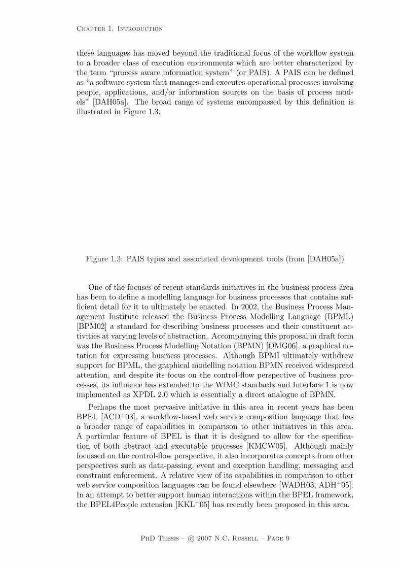
these languages has moved beyond the traditional focus of the workflow systemto a broader class of execution environments which are better characterized bythe term “process aware information system” (or PAIS). A PAIS can be definedas “a software system that manages and executes operational processes involvingpeople, applications, and/or information sources on the basis of process mod-els” [DAH05a]. The broad range of systems encompassed by this definition isillustrated in Figure 1.3.
Figure 1.3: PAIS types and associated development tools (from [DAH05a])
One of the focuses of recent standards initiatives in the business process areahas been to define a modelling language for business processes that contains suf-ficient detail for it to ultimately be enacted. In 2002, the Business Process Man-agement Institute released the Business Process Modelling Language (BPML)[BPM02] a standard for describing business processes and their constituent ac-tivities at varying levels of abstraction. Accompanying this proposal in draft formwas the Business Process Modelling Notation (BPMN) [OMG06], a graphical no-tation for expressing business processes. Although BPMI ultimately withdrewsupport for BPML, the graphical modelling notation BPMN received widespreadattention, and despite its focus on the control-flow perspective of business pro-cesses, its influence has extended to the WfMC standards and Interface 1 is nowimplemented as XPDL 2.0 which is essentially a direct analogue of BPMN.
Perhaps the most pervasive initiative in this area in recent years has beenBPEL [ACD+03], a workflow-based web service composition language that hasa broader range of capabilities in comparison to other initiatives in this area.A particular feature of BPEL is that it is designed to allow for the specifica-tion of both abstract and executable processes [KMCW05]. Although mainlyfocussed on the control-flow perspective, it also incorporates concepts from otherperspectives such as data-passing, event and exception handling, messaging andconstraint enforcement. A relative view of its capabilities in comparison to otherweb service composition languages can be found elsewhere [WADH03, ADH+05].In an attempt to better support human interactions within the BPEL framework,the BPEL4People extension [KKL+05] has recently been proposed in this area.
PhD Thesis – c© 2007 N.C. Russell – Page 9

Chapter 1. Introduction
1.2 Problem statement
Process-aware information systems are becoming increasingly pervasive in themodern business environment as organizations seek to automate and optimizelarger, more strategic sections of their overall business process portfolio. As theconceptual understanding of the various perspectives associated with a businessprocess and the available enabling technologies have matured, the system focushas shifted from the data-driven approaches on which the notion of informationsystems was originally founded to a more holistic notion of a business process.
However, despite the fact that an increasingly broad view is being taken ofthe factors that are pertinent to the definition of a business process, there is anotable absence of a formal foundation on which this definition can be based.Moreover, the relevant aspects of these perspectives that should be captured in adesign-time model of a business process and the manner in which they should beenacted at runtime are subject to varying interpretations. These ambiguities leadto potential uncertainties and variations when business processes are enacted inthe context of PAIS.
These ambiguities are a consequence of two main factors. The first of thesefactors is that there is no commonly agreed conceptual definition of the coreconstructs of a business process. Moreover, not only are the common elements ofa business process and their characteristics subject to debate, the relationshipsbetween these elements are also unclear.
The second factor relates to the manner in which the core constructs of abusiness process are actually enacted at runtime. Given the varying semanticsplaced on individual elements, it is not surprising that they are enacted in distinctways in differing enabling technologies. Moreover, it is increasingly clear that evenwidely supported (and supposedly well understood) constructs (e.g. the OR-join,the AND-join) are subject to varying implementations (see e.g. [KHA03]) and insome situations, their use can actually lead to paradoxes (see [ADK02] for detailson how the combination of OR-joins and loops in a process model can lead to the“vicious circle paradox” where the intended operation of the model is unclear).
In order to resolve these issues, a comprehensive definition is required of thefundamental constructs that make up a business process and the manner in whichthey interrelate. This definition must be based on a formal foundation in orderto remove any potential for ambiguity in the interpretation of these concepts. Itmust also facilitate the execution of a business process described in terms of theseconstructs in a deterministic way. Associated with these issues are the followingrelated research questions:
• What are the fundamental constructs that comprise a business process andwhat is the relationship between them?
• What are the attributes of these constructs and how do they influence themanner in which the constructs are enacted?
• Can the enactment of these constructs be described in a precise way?
• Can these constructs be described and integrated in a manner that is ap-plicable to a wide variety of PAIS?
PhD Thesis – c© 2007 N.C. Russell – Page 10

Chapter 1. Introduction
1.3 Solution criteria
In order to ensure that we have a clear definition of the qualities that a suitablesolution to the problems identified in the preceding section should demonstrate,we nominate the following criteria as a means of assessment.
1.3.1 Formality
One of the characterizing aspects of the current state of business process mod-elling is the absence of a formal basis for defining the core constructs of a businessprocess and the manner in which it should be enacted. A particularly significantshortcoming is the lack of support for capturing the semantics of a businessprocess (i.e. details associated with its fundamental intention, content and oper-ation). There are initial attempts at providing a foundation for specific aspectsof business process modelling, in particular process modelling and organizationalmodelling, however the field as a whole lacks a rigorous, integrated foundationthat encompasses all areas of a business process. This paucity increases the overallpotential for ambiguity when enacting a business process model. For this reason,any approach to language design for PAIS must be underpinned by a completeand unambiguous description of both its syntax and semantics.
1.3.2 Suitability
In order for a modelling language to have the broadest applicability to a problemdomain, it must provide support for the capture and enactment of as wide arange as possible of the requirements encountered in its field of usage. Keyto effective capture is the ability of the language to record all of the aspectsrelevant to a given requirement in a form that accords with its actual occurrencein the problem domain, i.e. there should not be a need for significant conceptualreorganization in order for a requirement to be recorded and in general terms,the constructs available in a modelling language should correlate relatively closelywith the concepts in associated application domains in which it will be employed.
1.3.3 Conceptuality
The modelling language should only focus on concepts that are directly relevantto the business process domain. Issues and constructs that are not relevant tothis area should be ignored. Any concepts that form part of the language shouldbe described at a conceptual level and be independent of specific technologicalor implementation-related considerations. Resultant models should be portableacross a wide range of potential enactment technologies and the manner in whicha model is interpreted must be independent of the environment in which it issubsequently implemented. To this end, it is vital that no aspect of the modellinglanguage relies on specific characteristics of underlying enactment technologies.
PhD Thesis – c© 2007 N.C. Russell – Page 11

Chapter 1. Introduction
1.3.4 Enactability
Ultimately, there is no benefit in proposing a business process modelling languagethat is not capable of being enacted. This may seem an obvious statement, butseveral recent initiatives in this area have proposed language elements that arenot able to be enacted without some degree of ambiguity [OADH06, RAHW06].Of particular interest is the ability of the business process language to facili-tate validation activities on process models both to establish their consistencyand correctness but also for more detailed investigations in regard to their likelyperformance in actual usage and potential areas for optimization.
1.3.5 Comprehensibility
The choice of modelling formalism must not limit its usefulness or accessibilityby end users. The motivation for this research is to provide a comprehensiveconceptual foundation for PAIS that has general applicability. Its utility will onlybe proven if it is capable of use by a broad range of business and IT practitionerswithout requiring specialist training. To this end, the modelling language willneed to display two key characteristics:
• Ease of capture – it should allow for the direct capture of all aspects of abusiness process pertinent to its enactment without requiring the format ofspecific aspects to be simplified or changed markedly in order to facilitatetheir accurate representation; and
• Ease of interpretation – once a business process has been captured usingthe language, the expected runtime semantics associated with the modelshould be clearly and precisely understood.
1.4 Approach
This thesis centres on the development of a formal foundation for PAIS. In orderto achieve this vision, two distinct research activities are undertaken.
1.4.1 Identification of the core constructs of a businessprocess
In order to establish a general foundation for PAIS, it is first necessary to identifythe core constructs of a business process which a PAIS may be required to enact.In this research, a business process is considered to be composed of four orthog-onal perspectives: control-flow, data, resource and exception handling. For eachof these perspectives an empirical survey of commercial products and modellingformalisms is undertaken, enabling the identification and delineation of generic,recurring constructs. For the first three perspectives these constructs are pre-sented in the form of patterns which describe their form, provide examples ofand motivations for their usage, discuss the manner in which they may be imple-mented and potential issues that may arise as a result of their usage (and where
PhD Thesis – c© 2007 N.C. Russell – Page 12

Chapter 1. Introduction
possible, solutions to these issues). For the exception handling perspective, theyform the basis of a framework for classifying exception handling capabilities.
1.4.2 Synthesis of the patterns into a modelling and en-actment language for PAIS
The catalogue of patterns identified by the preceding research activity providesthe basis for the development of a comprehensive language for describing businessprocesses. Being based on rich foundations, the language is able to be used notonly for modelling purposes, but also contains sufficient detail about a businessprocess to enable it to be directly enacted. The broad range of concepts that itembodies also ensures that it is suitable for use with the wide range of technolo-gies which fall under the PAIS umbrella whilst still retaining its own conceptualand technological independence. As part of the definition of the language, acomprehensive formalization is provided which includes an abstract syntax andoperational semantics for each of the language constructs thus providing an un-ambiguous interpretation of how each language element should be realized in anoperational context. The semantic model for the language takes the form of aColoured Petri net (CP-net) and is developed using CPN Tools [Jen97]. TheCPN Tools environment allows a CP-net to be executed, consequently it is possi-ble to to take an instance of the semantic model and directly execute it, therebydemonstrating the capabilities of the language firsthand.
1.5 Publications
The following papers have been published either based on or in reference to theresearch findings presented in this thesis:
• N. Russell, A.H.M. ter Hofstede, D. Edmond and W.M.P. van der Aalst,Workflow Data Patterns, QUT Technical Report, FIT-TR-2004-01, Queens-land University of Technology, Brisbane, Australia, 2004.
• N. Russell, A.H.M. ter Hofstede, D. Edmond and W.M.P. van der Aalst,Workflow Resource Patterns, BETA Working Paper Series, WP 127, Eind-hoven University of Technology, Eindhoven, The Netherlands, 2004.
• N. Russell, W.M.P. van der Aalst, A.H.M. ter Hofstede and D. Edmond,Workflow Resource Patterns: Identification, Representation and Tool Sup-port. In O. Pastor and J. Falcao e Cunha, editors, Proceedings of the 17thConference on Advanced Information Systems Engineering (CAiSE’05), vol-ume 3520 of Lecture Notes in Computer Science, pages 216–232. Springer-Verlag, Berlin, 2005.
• N. Russell, A.H.M. ter Hofstede, D. Edmond and W.M.P. van der Aalst,Workflow Data Patterns: Identification, Representation and Tool Support.In L. Delcambre, C. Kop, H.C. Mayr, J. Mylopoulos, and O. Pastor, editors,24nd International Conference on Conceptual Modeling (ER 2005), volume
PhD Thesis – c© 2007 N.C. Russell – Page 13

Chapter 1. Introduction
3716 of Lecture Notes in Computer Science, pages 353-368. Springer-Verlag,Berlin, 2005.
• N. Russell, W.M.P. van der Aalst, A.H.M. ter Hofstede and P. Wohed,On the Suitability of UML Activity Diagrams for Business Process Mod-elling. In Markus Stumptner, Sven Hartmann, and Yasushi Kiyoki, editors,Proceedings of the Third Asia-Pacific Conference on Conceptual Modelling(APCCM 2006), volume 53 of Conferences in Research and Practice inInformation Technology series (CRPIT), pages 95-104, Hobart, Australia,2006. ACS.
• N. Russell, W.M.P. van der Aalst, and A.H.M. ter Hofstede, Workflow Ex-ception Patterns, In E. Dubois and K. Pohl, editors, Proceedings of the18th International Conference on Advanced Information Systems Engineer-ing (CAiSE’06), volume 4001 of Lecture Notes in Computer Science, pages288-302. Springer-Verlag, Berlin, Germany, 2006.
• N. Russell, A.H.M. ter Hofstede, W.M.P. van der Aalst, and N. Mulyar,Workflow Control-Flow Patterns: A Revised View. BPM Center ReportBPM-06-22, BPMcenter.org, 2006.
• N. Russell, A.H.M. ter Hofstede, D. Edmond and W.M.P. van der Aalst,newYAWL: Achieving Comprehensive Patterns Support in Workflow for theControl-Flow, Data and Resource Perspectives, BPM Center Report BPM-07-05, BPMcenter.org, 2007.
• P. Wohed, W.M.P. van der Aalst, M. Dumas, A.H.M. ter Hofstede and N.Russell. Pattern-based Analysis of UML Activity Diagrams, BETA WorkingPaper Series, WP 129, Eindhoven University of Technology, Eindhoven, TheNetherlands, 2004.
• W.M.P. van der Aalst, M. Dumas, A.H.M. ter Hofstede, N. Russell, H.M.W.Verbeek and P. Wohed, Life After BPEL?, In M. Bravetti, L. Kloul, andG. Zavattaro, editors, WS-FM 2005, volume 3670 of Lecture Notes in Com-puter Science, pages 35-50. Springer-Verlag, Berlin, 2005.
• P. Wohed, W.M.P. van der Aalst, M. Dumas, A.H.M. ter Hofstede and N.Russell, Pattern-Based Analysis of the Control-Flow Perspective of UMLActivity Diagrams, In L. Delcambre, C. Kop, H.C. Mayr, J. Mylopoulos, andO. Pastor, editors, 24nd International Conference on Conceptual Modeling(ER 2005), volume 3716 of Lecture Notes in Computer Science, pages 63-78.Springer-Verlag, Berlin, 2005.
• P. Wohed, W.M.P. van der Aalst, M. Dumas, A.H.M. ter Hofstede and N.Russell, On the Suitability of BPMN for Business Process Modelling, In S.Dustdar, J.L. Faideiro, and A. Sheth, editors, International Conference onBusiness Process Management (BPM 2006), volume 4102 of Lecture Notesin Computer Science, pages 161-176. Springer-Verlag, Berlin, 2006.
• N. Mulyar, W.M.P. van der Aalst, A.H.M. ter Hofstede and N. Russell,Towards a WPSL: A Critical Analysis of the 20 Classical Workflow Control-flow Patterns, BPM Center Report BPM-06-18, BPMcenter.org, 2006.
PhD Thesis – c© 2007 N.C. Russell – Page 14

Chapter 1. Introduction
In addition, the research results contained in this thesis have formed the ba-sis for a comprehensive overhaul of the Workflow Patterns website (located atwww.workflowpatterns.com). This website includes a detailed description ofeach of the control-flow, data and resource patterns together with a comprehen-sive range of pattern animations, product evaluations, impact assessments andvendor feedback. Since being published in January 2007, the site has hosted over90,000 visitors.
1.6 Related work
The focus of this thesis is on the development of a comprehensive foundation forPAIS. Ultimately this takes the form of a business process modelling and enact-ment language which encompasses all of the constructs commonly encounteredin business process management. There are a number of related research effortsthat examine similar issues. These fall into three main categories, each of whichare discussed subsequently. In addition, there are references to related work atthe end of each of the chapters in Part One of the thesis which are more specificto the material presented in these sections.
1.6.1 Formalization of enactment languages for PAIS
As a means of describing the intended execution of a business process more pre-cisely, a number of initiatives have proposed formal execution models for businessprocesses. This work essentially proceeds in two directions – either describing theformalization of an existing language proposal such as BPEL or proposing a newlanguage describing process execution based on formal foundations.
Providing a formal basis for existing (informally defined) languages has be-come a popular research topic in recent years. Many of the commonly usedmodelling techniques have been subject to formalization efforts in an attemptto provide a precise semantics for their operation. EPCs have been formalizedusing Petri nets [Aal99] (although reaching a complete solution has been problem-atic [Kin06] given inherent ambiguities associated with the OR-join construct).UML 2.0 Activity Diagrams using π calculus [KKNR06], Petri nets [SH05] andusing a virtual machine approach [VK05] although in all cases, only a subset of theoverall language is formalized and the first two publications question whether acomplete semantics for the technique is possible. There has also been an attemptto provide a semantics for a subset of BPMN using Petri nets [DDO07]. Howeverthe language which has received overwhelming research focus has been BPEL andthere have been a multitude of proposals for a formal semantics for the languagebased on Petri nets, process algebras, abstract state machines and automata. Acomprehensive survey of the various approaches can be found elsewhere [BK07].
The other approach to establishing fully formalized languages for PAIS hasbeen to develop process modelling and enactment languages which are directlybased on formal foundations. There are a multitude of process modelling andexecution languages that are based on formal foundations such as Petri nets[Aal98] and process algebras such as CSP [Ste05] and π calculus [WG07]. However
PhD Thesis – c© 2007 N.C. Russell – Page 15

Chapter 1. Introduction
with a few exceptions such as COSA (a workflow system in which the control flowis based on Petri nets), none of these formally founded languages have had muchimpact on the development of commercial PAIS. Moreover, each of them tendsto focus on one particular aspect of a business process (e.g. control-flow).
1.6.2 Workflow patterns
One of the difficulties experienced in framing the content of a business processlanguage is the issue of suitability or understanding exactly what features arerequired to provide appropriate modelling and enactment support in a given usagedomain. Moreover, differences in the language constructs and representationalformat of distinct offerings make comparisons between them extremely difficult.In an effort to gain some insight into these issues, the Workflow Patterns Initiativewas conceived in the late nineties with the aim of identifying generic recurringconstructs in the workflow domain and describing them in the form of patterns.
The notion of patterns as a means of categorizing recurring problems andsolutions in a particular domain is generally attributed to Christopher Alexan-der [AIS77] as is the concept of a patterns language for describing the inter-relationships between specific patterns. The original patterns work centred onthe field of architecture, however the concept has general applicability and hasbeen used widely in a number of other domains. It has had most impact howeverin the field of information technology where patterns have been used to catego-rize the major concepts in a number of areas including system design [GHJV95],business analysis [Hay95, Fow96], business process design [EP00], software archi-tecture [BMR+96, SSRB00] and enterprise application integration [HW04].
The application of a patterns-based approach to the identification of genericworkflow constructs was first proposed by van der Aalst et al. [ABHK00], whoidentified several patterns relevant to the control-flow perspective of workflow sys-tems. This work was subsequently expanded to encompass twenty control-flowpatterns together with an analysis of their implementation in fifteen commercialand research workflow systems. It triggered research efforts in two main direc-tions: the first of these being the use of the patterns to evaluate the capabilitiesof a series of business process modelling languages and (proposed) web servicesstandards, the second being the use of the patterns to establish a formal basis forunderstanding the requirements of PAIS, subsequently to become known as theYAWL Initiative (which is discussed subsequently in Section 1.6.3).
Kiepuszewski [Kie03] used the patterns as part of an investigation into thefundamentals of workflow technology, in particular the expressiveness of variousapproaches to implementing control-flow constructs in workflow systems. Dumasand ter Hofstede [DH01] first utilized them to examine the capabilities of specificmodelling languages, in this case UML 1.4 Activity Diagrams, in an effort tounderstand its strengths, weaknesses and also to suggest areas for possible im-provement. This research strategy led to a series of subsequent investigations intothe suitability of languages including BPEL4WS [WADH03], BML [WPDH03],UML 2.0 Activity Diagrams [WAD+05] and BPMN [Whi04].
As the original control-flow patterns were documented in an informal, imper-ative style, there was immediate interest in providing a formal semantics for their
PhD Thesis – c© 2007 N.C. Russell – Page 16

Chapter 1. Introduction
operation. Several distinct proposals were developed based on techniques includ-ing π calculus [PW05], CCS [FSB06] and (somewhat less successfully) P/T nets[ZH05]. These proposals offered further clarity on the potential implementationof each of the patterns however they all focussed on the control-flow perspectiveand had the additional difficulty that they described each pattern in isolation.
1.6.3 Yet Another Workflow Language
One of the major learnings from the Workflow Patterns Initiative [AHKB03] wasthe recognition of a need for an expressive business process modelling languagethat encompassed the majority of the workflow patterns. This led to the devel-opment of the YAWL language [AH05], a modelling language based on a formalPetri net foundation that supports 19 of the 20 original control-flow patterns.YAWL has a formal semantics specified in the form of a label transition system,allowing it to exploit fundamental properties from Petri nets whilst incorporat-ing a number of higher-level patterns such as cancellation, multiple instances andOR-join semantics that are not inherently catered for by Petri nets. It also has agraphical syntax which supports higher-level modelling activities.
The YAWL language is implemented in the YAWL System [AADH04], anopen-source reference implementation of a workflow engine. It also has an associ-ated editor which allows process specifications to be created and modified as wellas an operational environment, of which the workflow engine is a part, togetherwith facilities such as a worklist handler that supports user interaction with theengine during process execution, a web services integration module and a graph-ical forms manager. The current YAWL language is based on the control-flowperspective and although the YAWL System has been partially extended to in-clude consideration of other perspectives (eg. data, resource, exception handling),neither language nor system has a comprehensive coverage of these. Furthermore,these extensions have not been formalized.
1.7 Outline of thesis
This thesis is organized in two parts: Part One identifies the core constructs in-herent in business processes as a series of patterns collections spanning four per-spectives. Chapter 2 describes 43 control-flow patterns that are relevant to PAIStogether with formal definitions of each of them. Chapter 3 presents a collectionof 40 data patterns that describe data characterization and usage. Chapter 4presents a collection of 43 resource patterns that describe work distribution andresource management. Chapter 5 examines the issue of exception handling inPAIS and identifies a series of patterns that capture specific aspects of exceptionhandling strategies. On the basis of these patterns, a generic graphical languagefor exception handling is presented. For each of these patterns collections, thereare evaluations of their implementation across a range of commercial offeringsincluding workflow systems, a case handling system, business process modellingformalisms and execution languages.
PhD Thesis – c© 2007 N.C. Russell – Page 17

Chapter 1. Introduction
Part Two of the thesis presents a formalization of the patterns in the form ofnewYAWL, a language for modelling and enacting business processes on whichPAIS can be grounded. Chapter 6 introduces the main language features ofnewYAWL and gives examples of their usage. Chapter 7 presents the syntax fornewYAWL together with a series of transformations which allow a design timenewYAWL model to be mapped to an executable newYAWL model. Chapter8 presents a semantic model for newYAWL that describes how the various con-structs embodied within it are realized. Chapter 9 reviews the capabilities ofnewYAWL from a patterns perspective. Chapter 10 concludes the thesis.
PhD Thesis – c© 2007 N.C. Russell – Page 18

Part I
Conceptual Foundations
19

This page is intentionally blank
20

There have been rapid advances in the technologies available for support-ing the design and enactment of business processes over the past decade. Asa consequence, there are now a wide range of systems that are driven by im-plicit or explicit business process models. This range of systems is collectivelyknown as process-aware information systems [DAH05b] and includes offerings asdiverse as workflow management (WFM), enterprise resource planning (ERP)and customer relationship management (CRM) systems. These technologies areincreasingly being used by organizations to underpin complex, mission-criticalbusiness processes. Yet despite the plethora of systems in both the commercialand research domains, there is a notable absence of core concepts that individualofferings could be expected to support or that could be used as a basis for com-parison. This absence differs markedly from other areas of information systemssuch as database design or transaction management which are based on formalconceptual foundations that have effectively become de facto standards.
In an effort to gain a better understanding of the fundamental concepts un-derpinning business processes, the Workflow Patterns Initiative was conceivedwith the goal of identifying the core architectural constructs inherent in workflowtechnology [AHKB03]. The original objective was to delineate the fundamentalrequirements that arise during business process modelling on a recurring basisand describe them in an imperative way. A patterns-based approach was takento describing these requirements as it offered both a language-independent andtechnology-independent means of expressing their core characteristics in a formthat was sufficiently generic to allow for its application to a wide variety of offer-ings.
In line with the traditional patterns approaches used by Alexander [AIS77]and the “Gang of Four” [GHJV95], that are based on a broad survey of existingproblems and practices within a particular domain, the initial work conductedas part of the Workflow Patterns Initiative identified twenty control-flow pat-terns were identified through a comprehensive evaluation of workflow systemsand process modelling formalisms. These patterns describe a series of constructsthat are embodied in existing offers in response to actual modelling requirements.The imperative approach employed in their description ensures that their intentand function is clearly presented without mandating a specific implementationapproach. An overriding objective was that they describe control-flow character-istics which it would be desirable to support in a given offering.
The publication of the original patterns in 2000 [AHKB03] had a galvanisingeffect on the workflow community. It provided clarity to concepts that were notpreviously well-defined and provided a basis for comparative discussion of thecapabilities of individual workflow systems. Amongst some vendors, the extent ofpatterns support soon became a basis for product differentiation and promotion.Although initially focussed on workflow systems, it soon became clear that thepatterns were applicable in a much broader sense and they were used to examinethe capabilities of business process modelling languages such as BPMN, XPDL,UML Activity Diagrams and EPCs, web service composition languages such asWCSI and business process execution languages such as BPML and BPEL.
As a consequence of this research, it soon became clear that the patterns ap-proach was an appropriate strategy for investigating the fundamental constructs
PhD Thesis – c© 2007 N.C. Russell – Page 21

inherent in PAIS. However two deficiencies existed in the original research: (1)the original control-flow patterns [AHKB03] were informally defined leading tovarying interpretations of their intent and operation and (2) a thorough descrip-tion of the constructs relevant to PAIS required a broader investigation of thevarious dimensions of a business process model (i.e. the original focus was on thecontrol-flow perspective, while the other perspectives are also highly relevant forPAIS).
Part 1 of this thesis provides a conceptual foundation for PAIS. It achieves thisthrough a thorough survey of current PAIS, standards and theory through whicha series of generic, recurring constructs are synthesized and presented in the formof patterns. Patterns are considered to constitute desirable characteristics thatsuch offerings should possess. Each pattern is presented using a standard formatwhich includes the following details:
• description – a summary of its functionality;
• examples – illustrative examples of its usage;
• motivation – the rationale for the use of the pattern;
• overview – an explanation of its operation including a detailed operationaldefinition where necessary;
• context – other conditions that must hold in order for the pattern to beused in a process context;
• implementation – how the pattern is typically realized in practice;
• issues – problems potentially encountered when using the pattern;
• solutions – how these problems can be overcome; and
• evaluation criteria – the conditions that an offering must satisfy in orderto be considered to support the pattern.
In general, the relative merit of individual patterns is underscored by theirimplementation in one or more existing PAIS, however there are five patternsthat have been identified which, whilst not directly observed in current offerings,describe meaningful constructs that are generalizations or extensions of otherpatterns.
For the purposes of this work, a business process is considered to consist ofthree orthogonal dimensions:
• the Control-Flow perspective, which describes the structure of a processmodel in terms its constituent activities and describes the manner in whichthey are implemented (considering both activities which have an underlyingimplementation and also those which are defined in terms of a subprocess)and the interconnections between them in terms of the overall flow of con-trol;
PhD Thesis – c© 2007 N.C. Russell – Page 22

• the Data perspective, which describes how data elements are defined andutilized during process execution; and
• the Resource perspective, which describes the overall organizational contextin which a process executes and the manner in which individual work itemscan be assigned to resources for subsequent execution.
These three perspectives capture the major components inherent in businessprocesses. Their correspondence with the dimensions identified in other popularframeworks is illustrated in Table 1.1. There is a relatively direct correlation be-tween the views identified in ARIS and CIMOSA and the patterns perspectives.For the Zachmann Framework, five of its six perspectives are captured by the pat-terns perspectives whilst the sixth – the Motivation perspective – must ultimatelybe decomposed into the other perspectives if the strategies and goals that it cap-tures are to be achieved by a business process. Five of the eleven perspectives inthe MOBILE workflow model are directly embodied by the pattern perspectivesidentified. MOBILE also denotes six other perspectives that it purports are “verysignificant” for the comprehensive specification of a process. Closer examinationof these perspectives suggests that in the main, these perspectives are actuallyinherent and interrelated properties of a comprehensive business process modelrather than distinct orthogonal dimensions. The Causality perspective corre-sponds to business rules and triggers which are generally characterized in termsof Control-Flow and Data. The History perspective is just the execution log oraudit trail for a process instance. By definition, it doesn’t exist until a processhas been executed, therefore it is problematic to consider it as part of a businessprocess model. The Security and Autonomy perspectives describe constraints onthe party (person or machine) actually able to undertake a given task. These arereadily encompassed by the Resource information captured for a business process.
Framework Pattern PerspectiveControl-Flow Data Resource
ARIS [Sch00] ControlFunction
Data Organization
CIMOSA [Ver96] Function InformationResource
Organization
Zachmann [Zac87] FunctionSchedule
Data OrganizationNetwork
MOBILE [JB96] Function,Operation,Behaviour
Information Organization
Table 1.1: Patterns perspectives in popular frameworks
There are however two additional perspectives in the MOBILE model thatmerit further consideration. The Quality and Integrity and Failure Recoveryperspectives involve taking action because a given business process does not meetwith expectations. This may be for various reasons including incorrect structureof the process model (quality issue), poor execution performance (quality issue),incorrect results being produced (integrity issue) or abnormal task termination
PhD Thesis – c© 2007 N.C. Russell – Page 23

(failure issue). In all of these situations, corrective action must be taken in thecontext of currently executing process instance(s). This may involve changesto Control-Flow, Data and/or Resource information associated with a businessprocess. Hence there is a fourth dimension to the description of a business processwhich involves the specification of exception handling strategies in response toexpected or unexpected events which may occur during execution.
These four dimensions (control-flow, data, resource and exception handling)provide the basis for describing the conceptual foundations of PAIS presented inthis part of the thesis. The following four chapters will present a taxonomy offundamental constructs in each of these perspectives. Before doing so however,there is some common terminology that needs to be introduced.
Throughout this thesis, a process or process model is assumed to be a descrip-tion of a business process in sufficient detail that it is able to be directly executedby a PAIS. A process model is composed of a number of tasks which are con-nected in the form of a directed graph. An executing instance of a process modelis called a case or process instance. There may be multiple cases of a particularprocess model running simultaneously, however each of these is assumed to havean independent existence and they typically execute without reference to eachother. There is usually a unique first node and a unique final node in a process.These are the starting and finishing points for each given process instance.
A task corresponds to a single unit of work. Four distinct types of task aredenoted: atomic, block, multiple-instance and multiple-instance block. We use thegeneric term components of a process to refer to all of the tasks that comprise agiven process model.
An atomic task is one which has a simple, self-contained definition (i.e. onethat is not described in terms of other tasks) and only one instance of the taskexecutes when it is initiated.
A block or composite task is a complex action which has its implementationdescribed in terms of a subprocess. When a block task is started, it passes controlto the first task(s) in its corresponding subprocess. This subprocess executes tocompletion and at its conclusion, it passes control back to the block task.
A multiple-instance task is a task that may have multiple distinct executioninstances running concurrently within the same process instance. Each of theseinstances executes independently. Only when a nominated number of these in-stances have completed is the task following the multiple instance task initiated.
A multiple-instance block task is a combination of the two previous constructsand denotes a task that may have multiple distinct execution instances each ofwhich is block structured in nature (i.e. each has a corresponding subprocess).
Each invocation of a task that executes is termed a work item. Usually thereis one work item initiated for each task in a given case however in the case ofa multiple-instance task, there may be several associated work items that arecreated when the task is initiated. Similarly, where a task forms part of a loop,a distinct work item is created for each iteration.
In general a work item is directed to a resource for execution (although aresource is not required to undertake automatic tasks). There are a variety ofways in which this may be achieved which will be discussed subsequently.
PhD Thesis – c© 2007 N.C. Russell – Page 24

A task may initiate one or several tasks when it completes (i.e. when a workitem corresponding to it completes). This is illustrated by an arrow from thecompleting task to the task (or tasks) being initiated. Where a task is link toseveral subsequent tasks (i.e. it has several outgoing branches), this constitutesa split and the when the preceding task completes the thread of control may bepassed to one, several or all of the subsequent tasks. There are several distincttypes of splits, each of which is discussed in Chapter 2.
Similarly where several tasks are linked to a specific task (i.e. the task hasmultiple incoming branches), this constitutes a join. Depending on the typeof join, the task can only commence when one, several or all of the incomingbranches have completed. The actual behaviour depends on the specific type ofjoin and the various types of join are discussed in Chapter 2.
There are a number of other concepts and modelling assumptions that relateto business processes, however these are specific to a given perspective and forthis reason, their introduction will be deferred to the chapter to which they aremost relevant.
This part of the thesis presents a conceptual foundation for PAIS. It is or-ganized as follows: Chapters 2, 3, 4 and 5 present a taxonomy of fundamentalconstructs in the control-flow, data, resource and exception handling perspec-tives. For the first three of these perspectives (control-flow, data and resource),these constructs are described in the form of patterns.
The control-flow, data and resource perspectives are orthogonal to each otherand there is minimal interrelationship between them. The exception handlingperspective differs in this regard as it is based on all of these perspectives and itis responsible for dealing with undesirable events which may arise in each of them.Consequently the approach to describing the conceptual basis of the exceptionhandling perspective is a little different. First the major factors associated withexception handling are delineated and investigated in detail. On the basis of thiswork, a patterns-based strategy is developed for describing exception handlingstrategies in PAIS and the exception handling capabilities of a variety of contem-porary PAIS are assessed. Finally on the basis of the insights gained from theseactivities, a generic graphical exception handling language is proposed.
PhD Thesis – c© 2007 N.C. Russell – Page 25
Chapter 2. Control-Flow Perspective
Chapter 2
Control-Flow Perspective
The control-flow perspective focuses on describing the tasks that make up a pro-cess and enforcing the various control-flow dependencies that exist between them.There have been a variety of approaches proposed for describing control-flow inbusiness processes [AHD05] yet despite their common focus, there is a surpris-ingly degree of degree of disparity between individual language proposals, bothin relation to the range the fundamental constructs that they embody and theirindividual capabilities and more generally in terms of their relative expressivepower.
In 1999, the Workflow Patterns Initiative was established with the aim ofproviding a conceptual basis for process technology. It took a pragmatic approachto addressing this problem and based on a comprehensive survey of state ofthe art offerings, it identified 20 generic constructs relevant to the control-flowperspective and presented them in the form of patterns. In doing so, it providedclarity to a range of control-flow concepts that were not previously well-definedand established a basis for comparative discussion of the capabilities of individualofferings.
This chapter presents a major review of the control-flow perspective with twomain objectives: (1) to assess the relevance of the original control-flow patternsand determine whether they provide comprehensive coverage of the constructsencountered in the control-flow perspective and (2) to provide a formal definitionof each pattern in order to remove any potential ambiguities that may have previ-ously existed. Consequently, there are two main sections in this chapter: the firstbeing a review of the original patterns and the second being the identificationof 23 new control-flow patterns, some of them entirely new and some based onspecializations of existing patterns. For each of the patterns, a precise descriptionof its operation is provided in the form of a CP-net1. The operational support forthe pattern is also examined across a series of contemporary offerings in the busi-ness process management field including commercial workflow and case handlingproducts, and also business process modelling notations such as BPMN, EPCsand UML 2.0 Activity Diagrams, and business process execution languages suchas XPDL and BPEL. In order to provide an objective basis for these evaluations,
1CPN Tools is used for preparation and validation of these models, copies of which areavailable from http://www.workflowpatterns.com. More details on CPN Tools can be foundat http://wiki.daimi.au.dk/cpntools/.
PhD Thesis – c© 2007 N.C. Russell – Page 26

Chapter 2. Control-Flow Perspective
a definitive set of evaluation criteria for rating patterns support in a given offer-ing have been established. Details of these criteria are included for each pattern.Specific details of each of the offerings evaluated (including version details) areincluded in Section 2.5.
2.1 Context assumptions
As far as possible, each of the control-flow patterns is illustrated using CP-nets.This provides a precise description of each pattern that is both deterministicand executable. This approach becomes increasingly important with some ofthe revised pattern definitions (as well as for some of the new patterns) as theactual manner in which the pattern operates requires more detailed description.For readers that are not familiar with the CP-net modelling formalism, a briefintroduction is included in Section 2.2.
There are some blanket assumptions that apply to all of the CP-nets used inthis chapter. Each of them adopts a notation in which input places are labelledi1...in, output places are labelled o1...on, internal places are labelled p1...pn
and transitions are labelled A...Z. In the case where either places or transitionsserve a more significant role in the context of the pattern, they are given moremeaningful names (e.g. buffer or anti-place). In general, transitions are intendedto represent tasks or activities in processes and places are the preceding andsubsequent states which describe when the task can be enabled and what theconsequences of its completion are.
Unless stated otherwise, it is assumed that the tokens flowing through a CP-net that signify control-flow are typed CID (short for “Case ID”) and that eachexecuting case (i.e. process instance) has a distinct case identifier. Moreover, theCP-nets are intended to show the operation of a given pattern in the contextof a single case during execution. This allows the CP-nets to be simplified soas to illustrate the essence of the pattern and as such, they are not intended todemonstrate pattern operation where tokens relating to multiple distinct casesare flowing through the CP-net simultaneously.
For most patterns, the assumption is also made that the model is safe, i.e.that each place in the model can only contain at most one token (i.e. one threadof control for each case currently being executed). This provides clarity in regardto the way in which each of the CPN models describing pattern operation areintended to function.
Safe behaviour is not a mandatory quality of processes. Some of the sys-tems examined in this thesis do implement safe process models whilst others donot. Where a system does provide a safe execution environment, this is typicallyachieved in one of two ways: either (1) during execution, the state of a given caseis never allowed to transition into an unsafe state. This is the approach adoptedby COSA, which blocks a task’s execution where it has a token in the place im-mediately after it and allowing it to execute could potentially result in an unsafestate (i.e. the following place having two tokens in it). The other alternative (2)is to detect any unsafe situations that may arise and migrate them to safe states.An example of this is the strategy employed by Staffware (often referred to as
PhD Thesis – c© 2007 N.C. Russell – Page 27

Chapter 2. Control-Flow Perspective
the “Pac-Man approach”) where any additional triggerings received by a taskthat is currently executing are coalesced into the same thread of control which isdelivered to outgoing branches when the task completes. These variations in theways in which distinct offerings implement concurrency within a process instancelead to differences in the ranges of patterns that they are able to support and themeans by which they realize them.
2.2 An overview of coloured Petri nets
Coloured Petri nets are a variant of standard Petri nets proposed by Jensen[Jen97] that incorporate support for colour, time and hierarchy. The additionof these dimensions have resulted in CP-nets being particularly suited to themodelling and analysis of large, complex concurrent systems. The availability ofCPN Tools – a modelling and execution environment for CP-nets – has led totheir widespread use by academic and industry practitioners alike.
CP-nets are used in two distinct ways in this thesis.
1. To describe the operation of the control-flow patterns in a precise manner.
2. To define the operational semantics of the newYAWL reference languagefor PAIS.
In both cases, the major benefit of using CP-nets is that they provide amodelling formalism that is both deterministic and executable.
CP-nets are based on four main syntactic elements: places, transitions, arcsand inscriptions. Figure 2.1 provides an example of one of a CP-net.�� � � � ���� ��� �� �� �� �� � �� �� ��� ���� �� ��� ��� ������ ���� ����� ��
� �� ��� � ��� � ����� ��� ��� ���� � � ���� �� ��� �� ��
!�� �"Figure 2.1: Example of a CP-net process model
The format follows that normally associated with Petri nets with a few ad-ditions. Each of the places in the net is typed (illustrated by the label to thebottom right of each place). In Figure 2.1, all of the places have type INT whichrepresents an integer. Note that arbitrarily complex types are allowed. All tokenswhich reside in these places have a value defined by the type associated with theplace. As with traditional Petri nets, outgoing arcs from a place are connectedto a transition. Transitions can only be enabled when all input places that areconnected to them hold a token.
Variables can be defined in the context of a CP-net, each of which has aunique name and a defined type (which may either be a basic data type such as
PhD Thesis – c© 2007 N.C. Russell – Page 28

Chapter 2. Control-Flow Perspective
a Boolean value, integer or string, or alternatively can be a structured data typeformed from the basic types using list, tuple or union operators). Variable haveglobal scoping and are accessible throughout the net.
Each of the arcs in a CP-net have one or more variables associated with them,which are instantiated based on the data element received from the precedingplace or transition.
There are four other features of CP-nets that are used for illustrative purposesin this thesis:
• A guard may be specified for each transition. This is a logical expressionthat must evaluate to true in order for the transition to fire. Transition A
has an example of a guard – variable i must be greater than or equal toone in order for the transition to be enabled.
• Outgoing arcs from a transition can be conditional. Their value depends onthe evaluation of the condition associated with the arc when the precedingtransition has fired. Transition A has conditional outgoing arcs. Dependingon the value of variable i, one or the other of them is selected at runtime(the empty value corresponds to no token flowing down the arc).
• CP-nets are hierarchical and the operation of a given transition (called asubstitution transition) can be described in terms of a subprocess which isitself a CP-net. Transition B is an example of a substitution transition.
• ML functions (based on a variant of the Standard ML functional language)can be associated with a CP-net. These functions can be used in guards,arc conditions and also can form the body of a transition. Transition C
illustrates how a function can be used as the body of a transition. Whentransition C is triggered, the value of the token it receives (as variable i) ispassed to the function inc and the result of this function is passed on fromthe transition as output variable j.
There are a number of other features associated with CP-nets – the ability torepresent time within a model is one notable capability – however these featuresare not utilized within this thesis and hence are not discussed here.
2.3 A review of the original control-flow pat-
terns
This section examines the original twenty control-flow patterns and revises theirdefinitions. It assumes that the reader is familiar with the concepts and termi-nology embodied in the original research. Where this is not the case, the readeris referred to the original Workflow Patterns publication [AHKB03].
One of the major areas of ambiguity in regard to the original descriptions ofthe control-flow patterns related to varying interpretations of their applicabilityand operation. In an effort to remove this area of uncertainty, this section provides
PhD Thesis – c© 2007 N.C. Russell – Page 29

Chapter 2. Control-Flow Perspective
a detailed definition of the operational semantics of each pattern in the form of aCP-net diagram together with the context conditions that apply to the pattern.
It has become clear that there are a number of additional scenarios in thecontrol-flow perspective that require categorization. Moreover, several of theoriginal patterns would benefit from a more precise description in order to re-move potential ambiguities in relation to the concepts that they are intended torepresent. Indeed with a more rigorous foundation, it becomes possible to furtherrefine several of the patterns into forms that more effectively describe and distin-guish between the distinct situations to which they might be applicable. Specificchanges to the original pattern definitions are described below.
The original Synchronizing Merge pattern did not adequately differentiate be-tween possible implementation variations, each of which has a distinct semantics.Consequently, it has now been divided into three distinct patterns:
• the Structured Synchronizing Merge (WCP-7), which restricts the originalpattern to use in a structured process context and sees it take the form ofa join which is paired with a specific preceding Multi-Choice, i.e. there is aone-to-one correspondence between split and join;
• the Local Synchronizing Merge (WCP-37), which recognizes tractable OR-join implementations, based on conventions such as true/false token passing,that allow their evaluation to be based on information directly available tothe merge (i.e. local semantics) but which are unable to deal with arbitraryloops; and
• the General Synchronizing Merge (WCP-38), which denotes a general solu-tion to OR-join evaluation based on a thorough analysis of the current andpotential future states of a process instance (i.e. non-local semantics).
In a similar vein, the original Discriminator pattern did not differentiatebetween distinct implementation approaches and their ability to deal with con-currency within a process instance. It is now recognized as having three distinctforms:
• the Structured Discriminator (WCP-9), where it operates in a safe andstructured process context (i.e. it is assumed that each branch executesprecisely once before a reset takes place and there is a one-to-one corre-spondence between splits and joins) and always has a corresponding ParallelSplit which precedes it in the process;
• the Blocking Discriminator (WCP-28), where concurrency within a processinstance is dealt with by blocking additional execution threads within agiven branch until the discriminator has reset; and
• the Cancelling Discriminator (WCP-29), where remaining incoming bran-ches which are still executing after the discriminator fires are cancelled.
The Partial (or n-out-of-m) Join pattern, which had previously only beendenoted as a possible generalization of the Discriminator, is now also recognized
PhD Thesis – c© 2007 N.C. Russell – Page 30

Chapter 2. Control-Flow Perspective
as a pattern in its own right with three distinct forms: the Structured PartialJoin (WCP-30), the Blocking Partial Join (WCP-31) and the Cancelling PartialJoin (WCP-32).
The Structured Loop (WCP-21) pattern has been introduced to deal with morerestrictive forms of iteration such as while and repeat loops which are not ade-quately covered by the Arbitrary Cycles pattern. Similarly the Recursion pattern(WCP-22) covers repetitive task execution which is based on self-invocation.
The original multiple instance patterns assume that all task instances mustcomplete before a subsequent task can be enabled. In recognition that more ef-ficient means exist of implementing concurrency with respect to overall processexecution and determination as to when the process can proceed beyond the mul-tiple instance task, three new patterns have been introduced: the Static PartialJoin for Multiple Instances (WCP-34), the Cancelling Partial Join for Multi-ple Instances (WCP-35) and the Dynamic Partial Join for Multiple Instances(WCP-36).
The ability to respond to external signals within a process instance was notwell covered by the original patterns other than by the Deferred Choice (WCP-16) which allows a decision regarding possible execution paths to be based onenvironmental input. To remedy this, two new patterns are introduced to denotethe ability of external signals to affect process execution. These are the TransientTrigger (WCP-23) and the Persistent Trigger (WCP-24).
The Interleaved Parallel Routing pattern (WCP-17) is extended to two newpatterns:
• the Critical Section pattern (WCP-39), which provides the ability to preventconcurrent execution of specific parts of a process; and
• the Interleaved Routing pattern (WCP-40), which denotes situations wherea group of tasks can be executed in any order providing none of themexecute concurrently.
Previous notions of cancellation only related to individual tasks and completeprocess instances (cases). In order to deal with cancellation in a more generalsense, the Cancel Region pattern (WCP-25) has been introduced, which allowsfor arbitrary groups of tasks in a process to be cancelled during execution. Sim-ilarly, in recognition that the semantics of cancelling a multiple instance task isdifferent to that associated with cancelling a normal task, the Cancel MultipleInstance Task (WCP-26) pattern has also been included and there is also a Com-plete Multiple Instance Task (WCP-27) to handle the situation where a multipleinstance task is forced to complete during execution.
Other new inclusions are the Generalized AND-Join pattern (WCP-33) whichdefines a model of AND-join operation for use in highly concurrent processes,Thread Merge (WCP-41) and Thread Split (WCP-42) which provide for coales-cence and divergence of distinct threads of control along a single branch andExplicit Termination (WCP-43) which provides an alternative approach to defin-ing process completion.
The remainder of this section presents a revised description of the origi-nal twenty control-flow patterns previously presented in van der Aalst et al.
PhD Thesis – c© 2007 N.C. Russell – Page 31

Chapter 2. Control-Flow Perspective
[AHKB03]. Although this material is motivated by earlier research conductedas part of the Workflow Patterns Initiative, the descriptions for each of thesepatterns have been thoroughly revised and a new set of evaluations have beenundertaken. In several cases, detailed review of a pattern has indicated thatthere are potentially several distinct ways in which the original pattern could beinterpreted and implemented. In order to resolve these ambiguities, the reviseddefinition of the original pattern is based on the most restrictive interpretation ofits operation and to delineate this from other possible interpretations that couldbe made. In several situations, a substantive case exists for consideration of thesealternative operational scenarios and where this applies, these are presented inthe form of new control-flow patterns in Section 2.4.
2.3.1 Basic control-flow patterns
This class of patterns captures elementary aspects of process control and aresimilar to the definitions of these concepts initially proposed by the WorkflowManagement Coalition (WfMC) [Wor99].
Pattern WCP-1 (Sequence)
Description A task in a process is enabled after the completion of a precedingtask in the same process.
Synonyms Sequential routing, serial routing.
Examples
– The verify-account task executes after the credit card details have been cap-tured.
– The codacil-signature task follows the contract-signature task.– A receipt is printed after the train ticket is issued.
Motivation The Sequence pattern serves as the fundamental building block forprocesses. It is used to construct a series of consecutive tasks which executein turn one after the other. Two tasks form part of a Sequence if there is acontrol-flow edge from one of them to the next which has no guards or conditionsassociated with it.
Overview Figure 2.2 illustrates the Sequence pattern using CP-nets.
i1
CID
p1
CID
o1
CID
A Bc c c c
Figure 2.2: Sequence pattern
Context There is one context condition associated with this pattern: an instanceof the Sequence pattern cannot be started again until it has completed executionof the preceding thread of control (i.e. all places such as p1 in the Sequence mustbe safe).
Implementation The Sequence pattern is widely supported and all of the offer-ings examined directly implement it.
PhD Thesis – c© 2007 N.C. Russell – Page 32

Chapter 2. Control-Flow Perspective
Issues Although all of the offerings examined implement the Sequence pattern,there are however, subtle variations in the manner in which it is supported. In themain, these differences centre on how individual offerings deal with concurrencywithin a given process instance and also between distinct process instances. Inessence these variations are characterized by whether the offering implements asafe process model or not. In CP-net terms, this corresponds to whether each ofthe places in the process model such as that in Figure 2.2 are 1-bounded (i.e. canonly contain at most one token for a case) or not.
Solutions This issue is handled in a variety of differing ways. BPMN, XPDLand UML 2.0 Activity Diagrams assume the use of a “token-based” approach tomanaging process instances and distinguishing between them, although no detailsare given as to how this actually occurs. Further, although individual tokens areassumed to be conserved during execution of a process instance, it is possible fora task, split or join construct to actually add or remove tokens during executionbeyond what would reasonably be expected. Staffware simply ignores the issueand where a step receives two threads (or more) of execution at the same time,they are simply coalesced into a single firing of the step (thus resulting in raceconditions). COSA adopts a prevention strategy, both by implementing a safeprocess model and also by disabling the task(s) preceding a currently enabledtask and not allowing the preceding task(s) to fire until the subsequent task hascompleted.
Evaluation Criteria Full support for this pattern is demonstrated by any of-fering which supports an explicit representation of dependency (e.g. directed arc)between two tasks which specifies the execution sequence.
Pattern WCP-2 (Parallel Split)
Description The divergence of a branch into two or more parallel branches eachof which execute concurrently.
Synonyms AND-split, parallel routing, parallel split, fork.
Examples
– After completion of the capture enrolment task, run the create student profileand issue enrolment confirmation tasks simultaneously.
– When an intrusion alarm is received, trigger the despatch patrol task and theinform police task immediately.
– Once the customer has paid for the goods, pack them and issue a receipt.
Motivation The Parallel Split pattern allows a single thread of execution tobe split into two or more branches which can execute tasks concurrently. Thesebranches may or may not be re-synchronized at some future time.
Overview Figure 2.3 illustrates the implementation of the Parallel Split. Aftertask A has completed, two distinct threads of execution are initiated and tasks Band C can proceed concurrently.
Context There are no specific context conditions for this pattern.
Implementation The Parallel Split pattern is implemented by all of the offeringsexamined. It may be depicted either explicitly or implicitly in process models.
PhD Thesis – c© 2007 N.C. Russell – Page 33

Chapter 2. Control-Flow Perspective
i1
CID
p1
CID
p2
CID
o1
CID
o2
CID
A
B
C
c
c
c
c
c
c
c
Figure 2.3: Parallel split pattern
Where it is represented explicitly, a specific construct exists for the Parallel Splitwith one incoming edge and two or more outgoing edges. Where it is representedimplicitly, this can be done in one of two ways: either (1) the edge representingcontrol-flow can split into two (or more) distinct branches or (2) the task afterwhich the Parallel Split occurs has multiple outgoing edges which do not haveany conditions associated with them or where it does these conditions alwaysevaluate to true.
Of the offerings examined, Staffware, WebSphere MQ, FLOWer, COSA andiPlanet represent the pattern implicitly. SAP Workflow, EPCs and BPEL2 do sowith explicit branching constructs. UML 2.0 ADs, BPMN and XPDL allow it tobe represented in both ways.
Issues None identified.
Solutions N/A.
Evaluation Criteria Full support for this pattern is demonstrated by the pro-vision of a construct (either implicit or explicit) that allows the thread of controlat a given point in a process to be split into two or more concurrent branches.
Pattern WCP-3 (Synchronization)
Description The convergence of two or more branches into a single subsequentbranch such that the thread of control is passed to the subsequent branch whenall input branches have been enabled.
Synonyms AND-join, rendezvous, synchronizer.
Examples
– The despatch-goods task runs immediately after both the check-invoice andproduce-invoice tasks are completed.
– Cash-drawer reconciliation can only occur when the store has been closed andthe credit card summary has been printed.
Motivation Synchronization provides a means of reconverging the executionthreads of two or more parallel branches. In general, these branches are created
2In general, the two BPEL implementations examined – WebSphere BPEL (which is part ofWebSphere Process Server) and Oracle BPEL – provide a relatively faithful implementation ofthe BPEL 1.1 specification hence the evaluation results are identical for all three offerings. Forthis reason they are not listed individually in this chapter unless there is a variation betweenthem.
PhD Thesis – c© 2007 N.C. Russell – Page 34

Chapter 2. Control-Flow Perspective
using the Parallel Split (AND-split) construct earlier in the process model. Thethread of control is passed to the task immediately following the synchronizeronce all of the incoming branches have completed.
Overview The behaviour of the Synchronization pattern is illustrated by theCP-net model in Figure 2.4. The pattern contains an implicit AND-join, knownas the synchronizer, which is considered to be activated once it receives input onone of the incoming branches (i.e. at places p1 or p2). Similarly it is consideredto be reset (and hence can be re-enabled) once input has been received on eachincoming branch and the synchronizer has fired, removing these tokens.
i1
CID
i2
CID
p1
CID
p2
CID
o1
CID
A
B
C
c c
c
c c
c
c
Figure 2.4: Synchronization pattern
Context This pattern has the following context condition: once the synchronizerhas been activated and has not yet been reset, it is not possible for another signalto be received on the activated branch or for multiple signals to be received onany incoming branch. In other words, all input places to the synchronizer (e.g.p1 and p2) are safe.
Implementation Similar to the Parallel Split pattern, the synchronizer caneither be represented explicitly or implicitly in a process model. Staffware hasan explicit AND-join construct as do SAP Workflow, EPCs, BPMN and XPDL.Other offerings – WebSphere MQ, FLOWer, COSA, iPlanet and BPEL – representthis pattern implicitly through multiple incoming (and unconditional) controledges to a task. Only when each of these arcs has received the thread of controlcan the task be enabled. UML 2.0 ADs allow it to be represented in both ways.
Issues The use of the Synchronization pattern can potentially give rise to adeadlock in the situation where one of the incoming branches fails to deliver athread of control to the join construct. This could be a consequence of a designerror or that one of the tasks in the branch failing to complete successfully (e.g.as a consequence of it experiencing some form of exception) or because the threadof control is passed outside of the branch.
Solutions None of the offerings examined provide support for resolving this issuewhere the problem is caused by task failure in one of the incoming branches.Where this pattern is used in a structured context, the second possible cause ofdeadlock generally does not arise.
Evaluation Criteria Full support for this pattern is demonstrated by any of-fering which provides a construct which satisfies the description when used in acontext satisfying the context assumption.
PhD Thesis – c© 2007 N.C. Russell – Page 35
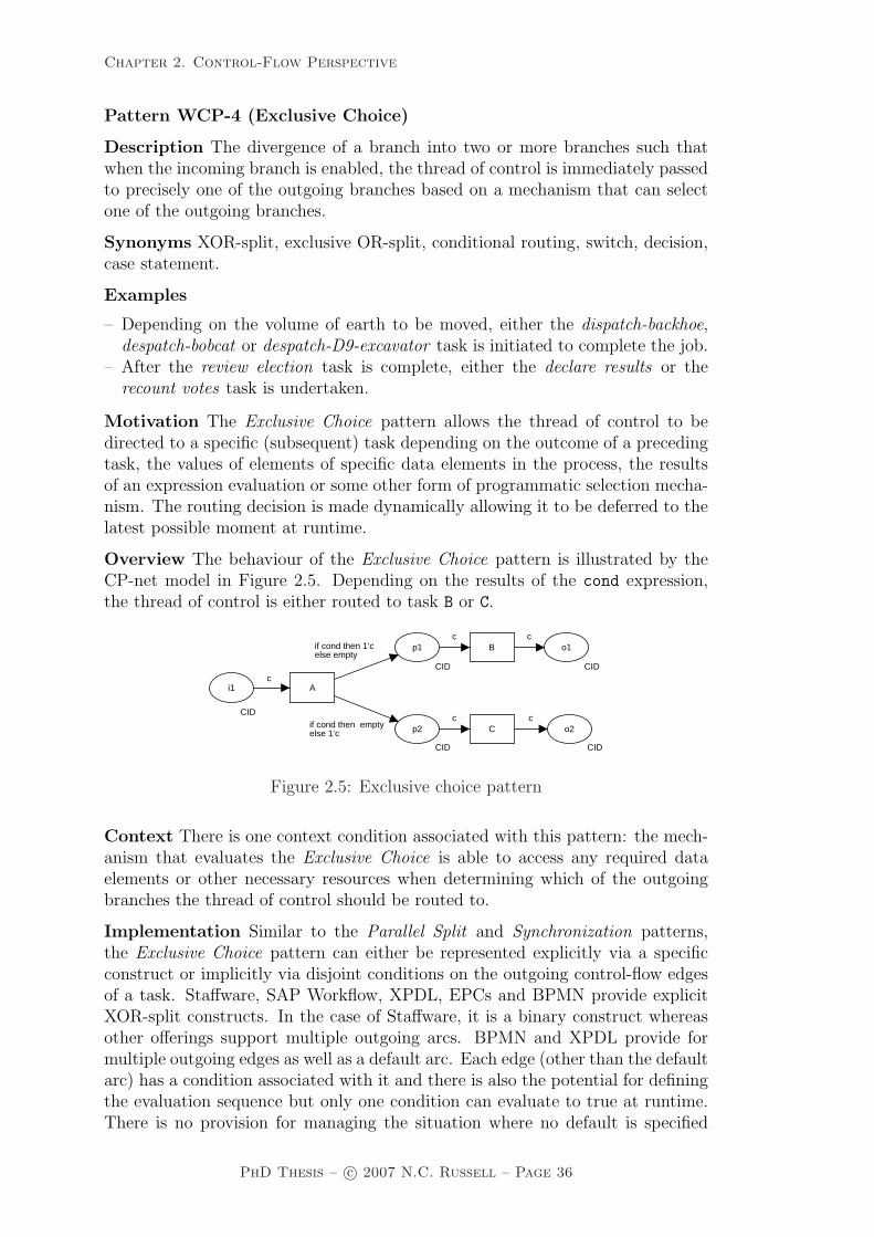
Chapter 2. Control-Flow Perspective
Pattern WCP-4 (Exclusive Choice)
Description The divergence of a branch into two or more branches such thatwhen the incoming branch is enabled, the thread of control is immediately passedto precisely one of the outgoing branches based on a mechanism that can selectone of the outgoing branches.
Synonyms XOR-split, exclusive OR-split, conditional routing, switch, decision,case statement.
Examples
– Depending on the volume of earth to be moved, either the dispatch-backhoe,despatch-bobcat or despatch-D9-excavator task is initiated to complete the job.
– After the review election task is complete, either the declare results or therecount votes task is undertaken.
Motivation The Exclusive Choice pattern allows the thread of control to bedirected to a specific (subsequent) task depending on the outcome of a precedingtask, the values of elements of specific data elements in the process, the resultsof an expression evaluation or some other form of programmatic selection mecha-nism. The routing decision is made dynamically allowing it to be deferred to thelatest possible moment at runtime.
Overview The behaviour of the Exclusive Choice pattern is illustrated by theCP-net model in Figure 2.5. Depending on the results of the cond expression,the thread of control is either routed to task B or C.
i1
CID
p1
CID
p2
CID
o1
CID
o2
CID
A
B
C
c
if cond then 1‘c else empty
c
if cond then emptyelse 1‘c
c
c
c
Figure 2.5: Exclusive choice pattern
Context There is one context condition associated with this pattern: the mech-anism that evaluates the Exclusive Choice is able to access any required dataelements or other necessary resources when determining which of the outgoingbranches the thread of control should be routed to.
Implementation Similar to the Parallel Split and Synchronization patterns,the Exclusive Choice pattern can either be represented explicitly via a specificconstruct or implicitly via disjoint conditions on the outgoing control-flow edgesof a task. Staffware, SAP Workflow, XPDL, EPCs and BPMN provide explicitXOR-split constructs. In the case of Staffware, it is a binary construct whereasother offerings support multiple outgoing arcs. BPMN and XPDL provide formultiple outgoing edges as well as a default arc. Each edge (other than the defaultarc) has a condition associated with it and there is also the potential for definingthe evaluation sequence but only one condition can evaluate to true at runtime.There is no provision for managing the situation where no default is specified
PhD Thesis – c© 2007 N.C. Russell – Page 36
Chapter 2. Control-Flow Perspective
and none of the branch conditions evaluate to true nor where more than onebranch condition evaluates to true (simultaneously) and no evaluation sequenceis specified. SAP Workflow provides three distinct means of implementing thispattern: (1) based on the evaluation of a Boolean expression one of two possiblebranches chosen, (2) one of multiple possible branches is chosen based on the valueof a specific data element (each branch has a nominated set of values which allowit to be selected and each possible value is assigned to exactly one branch) and (3)based on the outcome of a preceding task, a specific branch is chosen (a uniquebranch is associated with each possible outcome). UML 2.0 ADs also providea dedicated split construct although it is left to the auspices of the designer toensure that the conditions on outgoing edges are disjoint (e.g. the same constructcan be used for OR-splits as well). Likewise EPCs support the pattern in asimilar fashion. The other offerings examined – WebSphere MQ, FLOWer, COSA,iPlanet and BPEL – represent the pattern implicitly, typically via conditions onthe outgoing control-flow edges from a task which must be specified in such away that they are disjoint.
Issues One of the difficulties associated with this pattern is ensuring that pre-cisely one outgoing branch is triggered when the Exclusive Choice is executed.
Solutions The inclusion of default outgoing arcs on XOR-split constructs is anincreasingly common means of ensuring that an outgoing branch is triggered (andhence the thread of control continues in the process instance) when the XOR-splitis enabled and none of the conditions on outgoing branches evaluate to true. Anassociated issue is ensuring that no more than one branch is triggered. There aretwo possible approaches to dealing with this issue where more than one of thearc conditions will potentially evaluate to true. The first of these is to randomlyselect one of these arcs and allow it to proceed whilst ensuring that none of theother outgoing arcs are enabled. The second option, which is more practical inform, is to assign an evaluation sequence to the outgoing arcs which defines theorder in which arc conditions will be evaluated. The means of determining whicharc is triggered then becomes one of evaluating the arc conditions in sequentialorder until one evaluates to true. The arc is then triggered and the evaluationstops (i.e. no further arcs are triggered). In the event that none evaluate to true,then the default arc is triggered.
Evaluation Criteria Full support for this pattern is demonstrated by any of-fering which provides a construct which satisfies the description when used in acontext satisfying the context assumption.
Pattern WCP-5 (Simple Merge)
Description The convergence of two or more branches into a single subsequentbranch such that each enablement of an incoming branch results in the thread ofcontrol being passed to the subsequent branch.
Synonyms XOR-join, exclusive OR-join, asynchronous join, merge.
Examples
– At the conclusion of either the bobcat-excavation or the D9-excavation tasks,an estimate of the amount of earth moved is made for billing purposes.
PhD Thesis – c© 2007 N.C. Russell – Page 37

Chapter 2. Control-Flow Perspective
– After the cash-payment or provide-credit tasks, initiate the produce-receipt task.
Motivation The Simple Merge pattern provides a means of merging two or moredistinct branches without synchronizing them. As such, this presents the oppor-tunity to simplify a process model by removing the need to explicitly replicatea sequence of tasks that is common to two or more branches. Instead, thesebranches can be joined with a simple merge construct and the common set oftasks need only to be depicted once in the process model.
Overview Figure 2.6 illustrates the behaviour of this pattern. Immediately aftereither task A or B is completed, task C will be enabled. There is no considerationof synchronization.
i1
CID
i2
CID
p1
CID
o1
CID
A
B
C
c
c
c c
c
c
Figure 2.6: Simple merge pattern
Context There is one context condition associated with the pattern: the place atwhich the merge occurs (i.e. place p1 in Figure 2.6) is safe and can never containmore than one token.
Implementation Similar to patterns WCP2–WCP4 described above, this pat-tern can either be represented explicitly or implicitly. Staffware, SAP Workflowand UML 2.0 ADs provide specific join constructs for this purpose whereas it isrepresented implicitly in WebSphere MQ, FLOWer, COSA and BPEL. BPMNand XPDL allow it to be represented in both ways.
Issues One issue that can arise with the use of this pattern occurs where it cannotbe ensured that the incoming place to the merge (p1) is safe.
Solutions In this situation, the context conditions for the pattern are not metand it cannot be used, however there is an alternative pattern – the Multi-Merge(WCP-8) – that is able to deal with the merging of branches in potentially unsafeprocess instances.
Evaluation Criteria Full support for this pattern is demonstrated by any of-fering which provides a construct which satisfies the description when used in acontext satisfying the context assumption.
2.3.2 Advanced branching and synchronization patterns
This section presents a series of patterns which characterize more complex branch-ing and merging concepts which arise in business processes. Although relativelycommonplace, these patterns are often not directly supported or even able tobe represented in many commercial offerings. The original control-flow patternsidentified four of these patterns: Multi-Choice, Synchronizing Merge, Multi-Mergeand Discriminator.
PhD Thesis – c© 2007 N.C. Russell – Page 38
Chapter 2. Control-Flow Perspective
In this thesis, the Multi-Choice and Multi-Merge have been retained in theirprevious form albeit with a more formal description of their operational semantics.For the other patterns however, it has been recognized that there are a numberof distinct alternatives to the manner in which they can operate. The originalSynchronizing Merge now provides the basis for three patterns: the StructuredSynchronizing Merge (WCP-7), the Local Synchronizing Merge (WCP-37) andthe General Synchronizing Merge (WCP-38).
In a similar vein, the original Discriminator pattern is divided into six distinctpatterns: the Structured Discriminator (WCP-9), the Blocking Discriminator(WCP-28), the Cancelling Discriminator (WCP-29), the Structured Partial Join(WCP-30), the Blocking Partial Join (WCP-31) and the Cancelling Partial Join(WCP-32). Three other additions that have been identified are the GeneralizedAND-Join (WCP-33) which identifies a more flexible AND-join variant useful inconcurrent processes, and the Thread Merge (WCP-41) and Thread Split (WCP-42) which provide for coalescence and divergence of distinct threads of controlalong a single branch.
Of these patterns, the original descriptions for the Synchronizing Merge andthe Discriminator are superseded by their structured definitions and are describedin detail in this section. The remaining new patterns are presented in Section 2.4.
Pattern WCP-6 (Multi-Choice)
Description The divergence of a branch into two or more branches such thatwhen the incoming branch is enabled, the thread of control is immediately passedto one or more of the outgoing branches based on a mechanism that selects oneor more outgoing branches.
Synonyms Conditional routing, selection, OR-split, multiple choice.
Example
– Depending on the nature of the emergency call, one or more of the despatch-police, despatch-fire-engine and despatch-ambulance tasks is immediately initi-ated.
Motivation The Multi-Choice pattern provides the ability for the thread ofexecution to be diverged into several concurrent threads in distinct branches ona selective basis. The decision as to whether to pass the thread of execution toa specific branch is made at runtime. It can be based on a variety of factorsincluding the outcome of a preceding task, the values of elements of specific dataelements in the process, the results of evaluating an expression associated withthe outgoing branch or some other form of programmatic selection mechanism.This pattern is essentially an analogue of the Exclusive Choice pattern (WCP-4)in which multiple outgoing branches can be enabled.
Overview The operation of the Multi-Choice pattern is illustrated in Figure 2.7.After task A has been triggered, the thread of control can be passed to one orboth of the following branches depending on the evaluation of the conditionsassociated with each of them.3
3As a general comment, the notation x‘c on an input arc to a CP-net transition means thatx instances of token c are required for the input arc to be enabled.
PhD Thesis – c© 2007 N.C. Russell – Page 39

Chapter 2. Control-Flow Perspective
i1
CID
p1
CID
p2
CID
o1
CID
o2
CID
A
B
C
c
if cond1then 1‘c else empty
if cond2then 1‘celse empty
c
c
c
c
Figure 2.7: Multi-choice pattern
Context There is one context condition associated with this pattern: the mecha-nism that evaluates the Multi-Choice is able to access any required data elementsor necessary resources when determining which of the outgoing branches thethread of control should be routed.
Implementation As with other branching and merging constructs, the Multi-Choice pattern can either be represented implicitly or explicitly. WebSphereMQ captures it implicitly via (non-disjoint) conditions on outgoing arcs from aprocess or block construct, COSA and iPlanet do much the same via overlappingconditions on outgoing arcs from tasks and outgoing routers respectively. BothCOSA and iPlanet allow for relatively complex expressions to be specified forthese outgoing branches and iPlanet also allows for procedural elements to formpart of these conditions. The modelling and business process execution languagesexamined tend to favour the use of explicit constructs for representing the pattern:BPEL via conditional links within the <flow> construct, UML 2.0 ADs via theForkNode with guards conditions on the outgoing arcs and EPCs via textualnotations to the OR-split construct. BPMN and XPDL provide three alternativerepresentations including the use of an implicit split with conditions on the arcs,an OR-split or a complex gateway.
Issues Two issues have been identified with the use of this pattern. First, aswith the Exclusive Choice, an issue that also arises with the use of this patternis ensuring that at least one outgoing branch is selected from the various optionsavailable. If this is not the case, then there is the potential for the process to stall.Second, where an offering does not support the Multi-Choice construct directly,the question arises as to whether there are any indirect means of achieving thesame behaviour.
Solutions With respect to the first issue, the general solution to this issue is toenforce the use of a default outgoing arc from a Multi-Choice construct whichis enabled if none of the conditions on the other outgoing arcs evaluate to trueat runtime. For the second issue, a work-around that can be used to supportthe pattern in most offerings is based on the use of an AND-split immediatelyfollowed by an (binary) XOR-split in each subsequent branch. Another is theuse of an XOR-split with an outgoing branch for each possible task combination,e.g. a Multi-Choice construct with outgoing branches to tasks A and B wouldbe modelled using an XOR-split with three outgoing branches – one to task A,another to task B and a third to an AND-split which then triggered both tasks Aand B. Further details on these transformations are presented by van der Aalstet al. [AHKB03].
PhD Thesis – c© 2007 N.C. Russell – Page 40

Chapter 2. Control-Flow Perspective
Evaluation Criteria Full support for this pattern is demonstrated by any of-fering which provides a construct which satisfies the description when used ina context satisfying the context assumption. Note that the work-around basedon XOR-splits and AND-splits is not considered to constitute support for thispattern as the decision process associated with evaluation of the Multi-Choice isdivided across multiple split constructs.
The first six patterns focus primarily on process structure and essentially cor-respond to specific constructs that can reasonably be expected to appear in aprocess language. Indeed the first five patterns are directly supported in all ofthe offerings examined and the majority of them also support the sixth as well.In each of these cases, the CP-net model presented to illustrate the pattern corre-sponds very closely to the actual realization of the pattern in individual offerings.
The remainder of the patterns that will be described have a distinct focus whichcentres on their actual behaviour in a process context. As with the first sixpatterns, their operation is also described in terms of a CP-net model, however theemphasis is on the actual semantics of the pattern being presented rather than theway in which it is realized or depicted. As a consequence there is not such a closestructural correspondence between the CP-net models for individual patternsand the form in which they are realized in individual offerings and the directreplication of the CP-net model in a specific process language does not necessarilydemonstrate support for the pattern. The CP-net provides semantics but it doesnot suggest a representation. In order to support a pattern, a dedicated constructis needed in an offering that embodies the semantics expressed by the CP-net.As indicated before, the focus is on suitability and not theoretical expressiveness(which is Turing complete in most cases).
Pattern WCP-7 (Structured Synchronizing Merge)
Description The convergence of two or more branches (which diverged earlier inthe process at a uniquely identifiable point) into a single subsequent branch suchthat the thread of control is passed to the subsequent branch when each activeincoming branch has been enabled. The Structured Synchronizing Merge occursin a structured context, i.e. there must be a single Multi-Choice construct earlierin the process model with which the Structured Synchronizing Merge is associatedand it must merge all of the branches emanating from the Multi-Choice. Thesebranches must either flow from the Multi-Choice to the Structured SynchronizingMerge without any splits or joins or they must be structured in form (i.e. balancedsplits and joins).
Synonyms Synchronizing join, synchronizer.
PhD Thesis – c© 2007 N.C. Russell – Page 41

Chapter 2. Control-Flow Perspective
Example
– Depending on the type of emergency, either or both of the despatch-police anddespatch-ambulance tasks are initiated simultaneously. When all emergencyvehicles arrive at the accident, the transfer-patient task commences.
Motivation The Structured Synchronizing Merge pattern provides a means ofmerging the branches resulting from a specific Multi-Choice (or OR-split) con-struct earlier in a process into a single branch. Implicit in this merging is thesynchronization of all of the threads of execution resulting from the precedingMulti-Choice.
Overview As already indicated, the Structured Synchronizing Merge patternprovides a means of merging the branches from a preceding Multi-Choice con-struct and synchronizing the threads of control flowing along each of them. It isnot necessary that all of the incoming branches to the Structured SynchronizingMerge are active in order for the construct to be enabled, however all of thethreads of control associated with the incoming branches must have reached theStructured Synchronizing Merge before it can fire.
One of the difficulties associated with the use of this pattern is knowing whenthe Structured Synchronizing Merge can fire. The Structured Synchronizing Mergeconstruct must be able to resolve the decision based on local information availableto it during the course of execution. Critical to this decision is knowledge ofhow many branches emanating from the preceding Multi-Choice are active andrequire synchronization. This is crucial in order to remove any potential for the“vicious circle paradox” [Kin06] to arise where the determination of exactly whenthe merge can fire is based on non-local semantics which by necessity includes aself-referencing definition and makes the firing decision inherently ambiguous.
Addressing this issue without introducing non-local semantics for the Struc-tured Synchronizing Merge can be achieved in several ways including (1) struc-turing of the process model following a Multi-Choice such that the subsequentStructured Synchronizing Merge will always receive precisely one trigger on eachof its incoming branches and no additional knowledge is required to make the de-cision as to when it should be enabled, (2) by providing the merge construct withknowledge of how many incoming branches require synchronization and (3) byundertaking a thorough analysis of possible future execution states to determinewhen the Synchronizing Merge can fire.
The first of these implementation alternatives forms the basis for this patternand is illustrated in Figure 2.8. The assumption associated with this alternativeis that the merge construct always occurs in a structured context, i.e. it is al-ways paired with a distinct preceding Multi-Choice. It is interesting to note thatthe combination of the Structured Synchronizing Merge and the preceding Multi-Choice (together with the intervening tasks) forms a structured component thatis compositional in form and can be incorporated in other structured processeswhilst retaining the overall structural form. This approach involves adding an al-ternate “bypass” path around each branch from the multi-merge to the StructuredSynchronizing Merge which is enabled in the event that the normal path is notchosen. The “bypass” path is merged with the normal path for each branch priorto the Structured Synchronizing Merge construct ensuring that it always gets a
PhD Thesis – c© 2007 N.C. Russell – Page 42
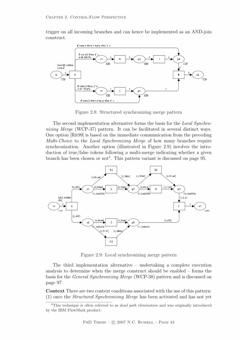
Chapter 2. Control-Flow Perspective
trigger on all incoming branches and can hence be implemented as an AND-joinconstruct.
� � � � � �� � � ��� ����� ��� ��� � ����� ����� ��� ��� � ����� ����� ��� ��� � ����� ����� ��� ��� � ���
������� � � ������� ��
� ��� ��� �� ����� ���
�� ��� �� ����� ��� �� ���
Figure 2.8: Structured synchronizing merge pattern
The second implementation alternative forms the basis for the Local Synchro-nizing Merge (WCP-37) pattern. It can be facilitated in several distinct ways.One option [Rit99] is based on the immediate communication from the precedingMulti-Choice to the Local Synchronizing Merge of how many branches requiresynchronization. Another option (illustrated in Figure 2.9) involves the intro-duction of true/false tokens following a multi-merge indicating whether a givenbranch has been chosen or not4. This pattern variant is discussed on page 95.
����� ��������� ��������� ��������� ��������� ��������� ����
����������� ��������� � ����� � ��
��������� � ����� � ����� � ����� � ����
��
����
������ ��� ����� �� ����� ��������
�� ���������� ��������� ���������� ���������� ���
Figure 2.9: Local synchronizing merge pattern
The third implementation alternative – undertaking a complete executionanalysis to determine when the merge construct should be enabled – forms thebasis for the General Synchronizing Merge (WCP-38) pattern and is discussed onpage 97.
Context There are two context conditions associated with the use of this pattern:(1) once the Structured Synchronizing Merge has been activated and has not yet
4This technique is often referred to as dead path elimination and was originally introducedby the IBM FlowMark product.
PhD Thesis – c© 2007 N.C. Russell – Page 43

Chapter 2. Control-Flow Perspective
been reset, it is not possible for another signal to be received on the activatedbranch or for multiple signals to be received on any incoming branch In otherwords, all input places to the Structured Synchronizing Merge (i.e. p4 and p5)are safe and (2) once the Multi-Choice has been enabled none of the tasks in thebranches leading to the Structured Synchronizing Merge can be cancelled beforethe merge has been triggered. The only exception to this is that it is possible forall of the tasks leading up to the Structured Synchronizing Merge to be cancelled.
Implementation The Structured Synchronizing Merge can be implemented inany process language which supports the Multi-Choice construct and can satisfythe context conditions discussed above. It is directly supported in WebSphereMQ, FLOWer, FileNet, BPMN, BPEL, XPDL and EPCs.
Issues One consideration that arises with the implementation of the OR-join isproviding a form that is able to be used in arbitrary loops and more complexprocess models which are not structured in form. The Structured SynchronizingMerge cannot be used in these contexts.
Solutions Both the Local Synchronizing Merge (WCP-37) and the General Syn-chronizing Merge (WCP-38) are able to be used in unstructured process models.The latter is also able to be used in arbitrary loops. The Local SynchronizingMerge tends to be more attractive from an implementation perspective as it isless computationally expensive than the General Synchronizing Merge.
Evaluation Criteria Full support for this pattern in an offering is evidencedby the availability of a construct which when placed in the proper context willsynchronize all active threads emanating from the corresponding Multi-Choice.
Pattern WCP-8 (Multi-Merge)
Description The convergence of two or more branches into a single subsequentbranch such that each enablement of an incoming branch results in the thread ofcontrol being passed to the subsequent branch.
Synonyms None.
Example
– The lay foundations, order materials and book labourer tasks occur in parallelas separate process branches. As each of them completes the quality reviewtask is run before that branch of the process finishes.
Motivation The Multi-Merge pattern provides a means of merging distinctbranches in a process into a single branch. Although several execution pathsare merged, there is no synchronization of control-flow and each thread of controlwhich is currently active in any of the preceding branches will flow unimpededinto the merged branch.
Overview The operation of this pattern is illustrated in Figure 2.10. Any threadsof control on incoming branches to p1 should be passed on to the outgoing branch.The analogy to this in CP-net terms, is that each incoming token to place p1
should be preserved. The distinction between this pattern and the Simple Mergeis that it is possible for more than one incoming branch to be active simultaneouslyand there is no necessity for place p1 to be safe.
PhD Thesis – c© 2007 N.C. Russell – Page 44

Chapter 2. Control-Flow Perspective
i1
CID
p1
CID
i2
CID
o1
CID
A
B
C
c
c
c
c
c c
Figure 2.10: Multi-merge pattern
Context There is one context condition associated with this pattern: the Multi-Merge must be associated with a specific preceding Multi-Choice construct.
Implementation iPlanet allows the Multi-Merge pattern to be implemented byspecifying a trigger condition for a task that allows it to be triggered when any ofits incoming routers are triggered. BPMN and XPDL directly implement it viathe XOR-join construct and UML 2.0 ADs have an analogue in the form of theMergeNode construct. EPCs also provide the XOR-join construct, however theyonly expect one incoming thread of control and ignore subsequent simultaneoustriggers, hence they do not support the pattern. FLOWer is able to support mul-tiple concurrent threads through dynamic subplans however its highly structurednature does not enable it to provide general support for the Multi-Merge pattern.Although COSA is based on a Petri net foundation, it only supports safe modelsand hence is unable to fully support the pattern. For example, both A and B inFigure 2.10 will block if there is a token in place p1. Staffware attempts to main-tain a safe process model by coalescing subsequent triggerings of a step whilst itis active into the same thread of control hence it is also unable to support thispattern. This behaviour is quite problematic as it creates a race condition inwhich all of the execution sequences ABC, BAC, ACBC and BCAB are possible.
Issues None identified.
Solutions N/A.
Evaluation Criteria Full support for this pattern is demonstrated by any of-fering which provides a construct which satisfies the description when used in acontext satisfying the context assumptions. Partial support is awarded to offer-ings that do not provide support for multiple branches to merge simultaneouslyor do not provide for preservation of all threads of control where this does occur.
Pattern WCP-9 (Structured Discriminator)
Description The convergence of two or more branches into a single subsequentbranch following a corresponding divergence earlier in the process model such thatthe thread of control is passed to the subsequent branch when the first incomingbranch has been enabled. Subsequent enablements of incoming branches do notresult in the thread of control being passed on. The Structured Discriminatorconstruct resets when all incoming branches have been enabled. The StructuredDiscriminator occurs in a structured context, i.e. there must be a single ParallelSplit construct earlier in the process model with which the Structured Discrim-inator is associated and it must merge all of the branches emanating from theStructured Discriminator. These branches must either flow from the Parallel
PhD Thesis – c© 2007 N.C. Russell – Page 45

Chapter 2. Control-Flow Perspective
Split to the Structured Discriminator without any splits or joins or they must bestructured in form (i.e. balanced splits and joins).
Synonym 1-out-of-m join.
Example
– When handling a cardiac arrest, the check breathing and check pulse tasks runin parallel. Once the first of these has completed, the triage task is commenced.Completion of the other task is ignored and does not result in a second instanceof the triage task.
Motivation The Structured Discriminator pattern provides a means of mergingtwo or more distinct branches in a process into a single subsequent branch suchthat the first of them to complete results in the subsequent branch being triggered,but completions of other incoming branches thereafter have no effect on (anddo not trigger) the subsequent branch. As such, the Structured Discriminatorprovides a mechanism for progressing the execution of a process once the first ofa series of concurrent tasks has completed.
Overview The operation of the Structured Discriminator pattern is illustratedin Figure 2.11. The () notation indicates a simple untyped token. Initially thereis such a token in place p2 (which indicates that the Discriminator is ready to beenabled). The first token received at any of the incoming places i1 to im results inthe Discriminator being enabled and an output token being produced in outputplace o1. An untyped token is also produced in place p3 indicating that theStructured Discriminator has fired but not yet reset. Subsequent tokens receivedat each of the other input places have no effect on the Structured Discriminator(and do not result in any output tokens in place o1). Once one token has beenreceived by each input place, the Structured Discriminator resets and can be re-enabled once again. This occurs when m-1 tokens have accumulated at place p1
allowing the reset transition to be enabled. Once again, the combination of theStructured Discriminator and the preceding Parallel Split can also be consideredas a structured component that is compositional in form and can be incorporatedin other structured processes whilst retaining the overall structural form.
���� �������� � ����� ���
������
�� � ����� ����� �� ����� ����� ���
�� ���
Figure 2.11: Structured discriminator pattern
There are two possible variants of this pattern that can be utilized in non-structured contexts. Both of which improve the applicability of the Structured
PhD Thesis – c© 2007 N.C. Russell – Page 46

Chapter 2. Control-Flow Perspective
Discriminator pattern whilst retaining its overall behaviour. First, the BlockingDiscriminator (WCP-28) removes the requirement that each incoming branchcan only be enabled once between Structured Discriminator resets. It allowseach incoming branch to be triggered multiple times although the construct onlyresets when one triggering has been received on each input branch. It is illustratedin Figure 2.12 and discussed in further detail on page 80.
������� �� ��������� ��
�� ���� ������ � ���� ���
���� ��� �� ������������ � �� �� ��������
������
����
�� ����� ��� ������ �������� ������� � ����� ������ �� ���
�� ���� ����� ���
Figure 2.12: Blocking discriminator pattern
The second alternative, the Cancelling Discriminator (WCP-29), improvesthe efficiency of the pattern further by preventing any subsequent tasks in the re-maining incoming branches to the Cancelling Discriminator from being enabledonce the first branch has completed. Instead the remaining branches are effec-tively put into a “bypass mode” where any remaining tasks are “skipped” henceexpediting the reset of the construct. It is illustrated in Figure 2.13 and discussedin further detail on page 81.
���� �
� ����
���� �������� � ��������
��
��
��� �
� �� ����� ������ �� ����� ����� ���
�� ���
Figure 2.13: Cancelling discriminator pattern
Context There are two context conditions associated with the use of this pattern:(1) once the Structured Discriminator has been activated and has not yet beenreset, it is not possible for another signal to be received on the activated branchor for multiple signals to be received on any incoming branch. In other words, all
PhD Thesis – c© 2007 N.C. Russell – Page 47

Chapter 2. Control-Flow Perspective
input places to the Structured Discriminator (i.e. i1 to im) are safe and (2) thereis a corresponding Parallel Split and once this has been enabled none of the tasksin the branches leading to the Structured Discriminator can be cancelled beforeit has been triggered. The only exception to this is that it is possible for all of thetasks leading up to the Structured Discriminator to be cancelled. It is interestingto note that a corollary of these context criteria is that correct behaviour of thepattern is assured and relies only on local information available to the StructuredDiscriminator at runtime.
Implementation The Structured Discriminator can be directly implemented iniPlanet by specifying a custom trigger condition for a task with multiple incomingrouters which only fires when the first router is enabled. BPMN and XPDLpotentially support the pattern with a COMPLEX-Join construct however it isunclear how the IncomingCondition for the join is specified. UML 2.0 ADs sharesa similar problem with its JoinNode construct. SAP Workflow provides partialsupport for this pattern via the fork construct although any unfinished branchesare cancelled once the first completes.
Issues One issue that can arise with the Structured Discriminator is that failureto receive input on each of the incoming branches may result in the processinstance (and possibly other process instances) stalling.
Solutions The alternate versions of this pattern provide potential solutions to theissue. The Blocking Discriminator allows multiple execution threads in a givenprocess instance to be handled by a single Blocking Discriminator (although asubsequent thread can only trigger the construct when inputs have been receivedon all incoming branches and the Blocking Discriminator has reset). The Can-celling Discriminator only requires the first thread of control to be received inan incoming branch. Once this has been received, the remaining branches areeffectively put into “bypass” mode and any remaining tasks in those branchesthat have not already been commenced are skipped (or cancelled) allowing thediscriminator to be reset as soon as possible.
Evaluation Criteria Full support for this pattern is demonstrated by any of-fering which provides a construct which satisfies the description when used ina context satisfying the context assumptions. It rates as partial support if theStructured Discriminator can reset without all tasks in incoming branches havingrun to completion.
2.3.3 Structural patterns
Structural patterns characterize design restrictions that specific process languagesmay have on the form of process model that they are able to represent and howthese models behave at runtime. There are two main areas that are of interest instructural terms: (1) the form of cycles or loops that can be represented withinthe process model and (2) whether the termination of a process instance must beexplicitly captured within the process model.
Looping is a common construct that arises during process modelling in situa-tions where individual tasks or groups of tasks must be repeated. Three distinctforms of repetition can be identified: Arbitrary Cycles, Structured Loops and Re-
PhD Thesis – c© 2007 N.C. Russell – Page 48
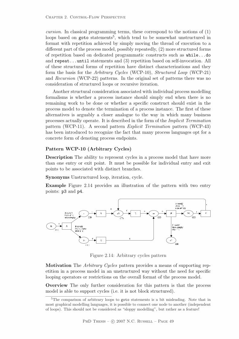
Chapter 2. Control-Flow Perspective
cursion. In classical programming terms, these correspond to the notions of (1)loops based on goto statements5, which tend to be somewhat unstructured informat with repetition achieved by simply moving the thread of execution to adifferent part of the process model, possibly repeatedly, (2) more structured formsof repetition based on dedicated programmatic constructs such as while...do
and repeat...until statements and (3) repetition based on self-invocation. Allof these structural forms of repetition have distinct characterizations and theyform the basis for the Arbitrary Cycles (WCP-10), Structured Loop (WCP-21)and Recursion (WCP-22) patterns. In the original set of patterns there was noconsideration of structured loops or recursive iteration.
Another structural consideration associated with individual process modellingformalisms is whether a process instance should simply end when there is noremaining work to be done or whether a specific construct should exist in theprocess model to denote the termination of a process instance. The first of thesealternatives is arguably a closer analogue to the way in which many businessprocesses actually operate. It is described in the form of the Implicit Terminationpattern (WCP-11). A second pattern Explicit Termination pattern (WCP-43)has been introduced to recognize the fact that many process languages opt for aconcrete form of denoting process endpoints.
Pattern WCP-10 (Arbitrary Cycles)
Description The ability to represent cycles in a process model that have morethan one entry or exit point. It must be possible for individual entry and exitpoints to be associated with distinct branches.
Synonyms Unstructured loop, iteration, cycle.
Example Figure 2.14 provides an illustration of the pattern with two entrypoints: p3 and p4. ���� �������� �� �� ���� ���� ����� ��� ���
�����������
� �� � �� � �� ������
����� �������� ��� �� �� � ��� �� �������� ��� �� ��
�� �������� �� �� ���
Figure 2.14: Arbitrary cycles pattern
Motivation The Arbitrary Cycles pattern provides a means of supporting rep-etition in a process model in an unstructured way without the need for specificlooping operators or restrictions on the overall format of the process model.
Overview The only further consideration for this pattern is that the processmodel is able to support cycles (i.e. it is not block structured).
5The comparison of arbitrary loops to goto statements is a bit misleading. Note that inmost graphical modelling languages, it is possible to connect one node to another (independentof loops). This should not be considered as “sloppy modelling”, but rather as a feature!
PhD Thesis – c© 2007 N.C. Russell – Page 49
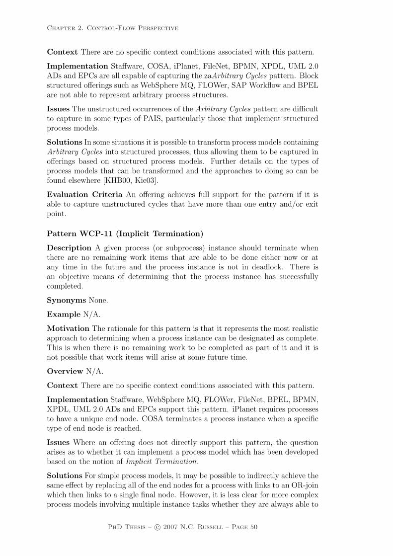
Chapter 2. Control-Flow Perspective
Context There are no specific context conditions associated with this pattern.
Implementation Staffware, COSA, iPlanet, FileNet, BPMN, XPDL, UML 2.0ADs and EPCs are all capable of capturing the zaArbitrary Cycles pattern. Blockstructured offerings such as WebSphere MQ, FLOWer, SAP Workflow and BPELare not able to represent arbitrary process structures.
Issues The unstructured occurrences of the Arbitrary Cycles pattern are difficultto capture in some types of PAIS, particularly those that implement structuredprocess models.
Solutions In some situations it is possible to transform process models containingArbitrary Cycles into structured processes, thus allowing them to be captured inofferings based on structured process models. Further details on the types ofprocess models that can be transformed and the approaches to doing so can befound elsewhere [KHB00, Kie03].
Evaluation Criteria An offering achieves full support for the pattern if it isable to capture unstructured cycles that have more than one entry and/or exitpoint.
Pattern WCP-11 (Implicit Termination)
Description A given process (or subprocess) instance should terminate whenthere are no remaining work items that are able to be done either now or atany time in the future and the process instance is not in deadlock. There isan objective means of determining that the process instance has successfullycompleted.
Synonyms None.
Example N/A.
Motivation The rationale for this pattern is that it represents the most realisticapproach to determining when a process instance can be designated as complete.This is when there is no remaining work to be completed as part of it and it isnot possible that work items will arise at some future time.
Overview N/A.
Context There are no specific context conditions associated with this pattern.
Implementation Staffware, WebSphere MQ, FLOWer, FileNet, BPEL, BPMN,XPDL, UML 2.0 ADs and EPCs support this pattern. iPlanet requires processesto have a unique end node. COSA terminates a process instance when a specifictype of end node is reached.
Issues Where an offering does not directly support this pattern, the questionarises as to whether it can implement a process model which has been developedbased on the notion of Implicit Termination.
Solutions For simple process models, it may be possible to indirectly achieve thesame effect by replacing all of the end nodes for a process with links to an OR-joinwhich then links to a single final node. However, it is less clear for more complexprocess models involving multiple instance tasks whether they are always able to
PhD Thesis – c© 2007 N.C. Russell – Page 50

Chapter 2. Control-Flow Perspective
be converted to a model with a single terminating node. Potential solutions tothis are discussed at length by Kiepuszewski et al. [KHA03].
It is worthwhile noting that some languages do not offer this construct onpurpose: the Implicit Termination pattern makes it difficult (or even impossible)to distinguish proper termination from deadlock. Often it is only through ex-amination of the process log that it is possible to determine if a particular casehas actually finished. Additionally, processes without explicit endpoints are moredifficult to use in compositions.
Evaluation Criteria An offering achieves full support if it is possible to havemultiple final nodes and the behaviour of these nodes satisfies the description forthe pattern.
2.3.4 Multiple instance patterns
Multiple instance patterns describe situations where there are multiple threadsof execution active in a process model which relate to the same task (and henceshare the same implementation definition). Multiple instances can arise in threesituations:
1. A task is able to initiate multiple instances of itself when triggered (thisform of task is denoted a multiple instance task);
2. A given task is initiated multiple times as a consequence of it receivingseveral independent triggerings, e.g. as part of a loop or in a process instancein which there are several concurrent threads of execution as might resultfrom a Multi-Merge for example; and
3. Two or more tasks in a process share the same implementation definition.This may be the same task definition in the case of a multiple instance taskor a common subprocess definition in the case of a block task. Two (ormore) of these tasks are triggered such that their executions overlap (eitherpartially or wholly).
Although all of these situations potentially involve multiple concurrent in-stances of a task or subprocess, it is the first of them that are most interestingas they require the triggering and synchronization of multiple concurrent taskinstances. This group of patterns focusses on the various ways in which theseevents can occur.
Similar to the differentiation introduced in the Advanced Branching and Syn-chronization Patterns to capture the distinction between the Discriminator andthe Partial Join pattern variants, three new patterns have been introduced torecognize alternative operational semantics for multiple instances. These are theStatic Partial Join for Multiple Instances (WCP-34), the Cancelling Partial Joinfor Multiple Instances (WCP-35) and the Dynamic Partial Join for Multiple In-stances (WCP-36), each of which is discussed in detail in Section 2.4.
PhD Thesis – c© 2007 N.C. Russell – Page 51

Chapter 2. Control-Flow Perspective
Pattern WCP-12 (Multiple Instances without Synchronization)
Description Within a given process instance, multiple instances of a task canbe created. These instances are independent of each other and run concurrently.There is no requirement to synchronize them upon completion. Each of theinstances of the multiple instance task that are created must execute within thecontext of the process instance from which they were started (i.e. they must sharethe same case identifier and have access to the same data elements) and each ofthem must execute independently from and without reference to the task thatstarted them.
Synonyms Multi threading without synchronization, spawn off facility.
Example
– A list of traffic infringements is received by the Transport Department. For eachinfringement on the list an Issue-Infringement-Notice task is created. Thesetasks run to completion in parallel and do not trigger any subsequent tasks.They do not need to be synchronized at completion.
Motivation This pattern provides a means of creating multiple instances of agiven task. It caters for situations where the number of individual tasks requiredis known before the spawning action commences, the tasks can execute indepen-dently of each other and no subsequent synchronization is required.
Overview There are two possible variants in the way in which this pattern canoperate. The first is illustrated by Figure 2.15 in which the create instance
task runs within a loop and the new task instances are created sequentially. Placep2 indicates the number of instances required and is decremented as each newinstance is created. New instances can only be created when the token in p2 has avalue greater than zero – the guard on the create instance task ensures this isthe case. When all instances have been created, the next task (B) can be enabled– again the guard on task B ensures this is also the case.
�������� ��� �� �
������ ��� ������������������ �
�� ����� ����� ����� ����� ����� ���
Figure 2.15: Multiple instances without synchronization (variant 1)
In Figure 2.16, the task instances are all created simultaneously. In bothvariants, it is a requirement that the number of new instances required is knownbefore the creation task commences. It is also assumed that task instances can
PhD Thesis – c© 2007 N.C. Russell – Page 52

Chapter 2. Control-Flow Perspective
be created that run independently (and in addition to the thread of control whichstarted them) and that they do not require synchronizing as part of this construct.
� � � ��������� �� � ��� � ���������� � �� ��� �� ��� �� ����� ��� �� ����� ���Figure 2.16: Multiple instances without synchronization (variant 2)
Context There is one context condition associated with this pattern: the numberof task instances (i.e. numinst) is known at design time and is a fixed value.
Implementation Most offerings – COSA, iPlanet, BPEL, BPMN, XPDL andUML 2.0 ADs – support the sequential variant of this pattern (as illustrated inFigure 2.15) with the task creation occurring within a loop. SAP Workflow alsodoes so, but with the limitation that a new process instance is started for eachtask instance invoked. BPMN also supports the second variant, as do Staffwareand FLOWer, and they provide the ability to create the required number of taskinstances simultaneously.
Issues None identified.
Solutions N/A.
Evaluation Criteria An offering achieves full support if it provides a constructthat satisfies the description for the pattern. Where the newly created taskinstances run in a distinct process instance to the task that started them or itcannot access the same data elements as the parent task, the offering achievesonly partial support.
Pattern WCP-13 (Multiple Instances with a priori Design-Time Know-ledge)
Description Within a given process instance, multiple instances of a task canbe created. The required number of instances is known at design time. Theseinstances are independent of each other and run concurrently. It is necessary tosynchronize the task instances at completion before any subsequent tasks can betriggered.
Synonyms None.
Example
– The Annual Report must be signed by all six Directors before it can be issued.
Motivation This pattern provides the basis for concurrent execution of a nom-inated task a predefined number of times. It also ensures that all task instancesare complete before subsequent tasks are initiated.
Overview Similar to WCP-12, the Multiple Instances without Synchronizationpattern, there are both sequential and simultaneous variants of this pattern il-lustrated in Figures 2.17 and 2.18 respectively. In both figures, task C is the onethat executes multiple times.
PhD Thesis – c© 2007 N.C. Russell – Page 53

Chapter 2. Control-Flow Perspective ������������ �������� �� �� ��� �� � �� ������� ������ �� ���� �� � ���� ���� ��� �� �
Figure 2.17: Multiple instances with a priori design-time knowledge (variant 1)� ��������� � � ��������� �� �� � �� � �� � �� � Figure 2.18: Multiple instances with a priori design-time knowledge (variant 2)
Context There is one context condition associated with this pattern: the numberof task instances (i.e. numinst) is known at design time and is a fixed value.
Implementation In order to implement this pattern, an offering must provide aspecific construct in the process model that is able to denote the actual number ofconcurrent task instances that are required. Staffware, FLOWer, SAP Workflowand UML 2.0 ADs support the simultaneous variant of the pattern through theuse of dynamic subprocedure, dynamic subplan, multi-line container element andExpansionRegion constructs respectively. BPMN and XPDL support both op-tions via the multi-instance loop task construct with the MI Ordering attributesupporting both sequential and parallel values depending on whether the tasksshould be started one-by-one or all together. Unlike other BPEL offerings whichdo not support this pattern, Oracle BPEL provides a <flowN> construct thatenables the creation of multiple concurrent instances of a task.
Issues Many offerings provide a work-around for this pattern by embedding someform of task invocation within a loop. These implementation approaches havetwo significant problems associated with them: (1) the task invocations occur atdiscrete time intervals and it is possible for the individual task instances to havedistinct states (i.e. there is no requirement that they execute concurrently) and(2) there is no consideration of the means by which the distinct task instanceswill be synchronized. These issues, together with the necessity for the designerto effectively craft the pattern themselves (rather than having it provided by theoffering) rule out this form of implementation from being considered as satisfyingthe requirements for full support.
Solutions One possibility that exists where this functionality is not provided byan offering but an analogous form of operation is required is to simply replicatethe task in the process-model. Alternatively a solution based on iteration can beutilized.
Evaluation Criteria Full support for this pattern is demonstrated by any of-fering which provides a construct which satisfies the description when used in acontext satisfying the context assumption. Although work-arounds are possible
PhD Thesis – c© 2007 N.C. Russell – Page 54

Chapter 2. Control-Flow Perspective
which achieve the same behaviour through the use of various constructs withinan offering such as task replication or loops, they have a number of shortcomingsand are not considered to constitute support for the pattern.
Pattern WCP-14 (Multiple Instances with a priori Run-Time Knowl-edge)
Description Within a given process instance, multiple instances of a task can becreated. The required number of instances may depend on a number of runtimefactors, including state data, resource availability and inter-process communica-tions, but is known before the task instances must be created. Once initiated,these instances are independent of each other and run concurrently. It is neces-sary to synchronize the instances at completion before any subsequent tasks canbe triggered.
Synonyms None.
Examples
– When diagnosing an engine fault, multiple instances of the check-sensor taskcan run concurrently depending on the number of error messages received.Only when all messages have been processed, can the identify-fault task beinitiated;
– In the review process for a paper submitted to a journal, the review paper task isexecuted several times depending on the content of the paper, the availabilityof referees and the credentials of the authors. The review process can onlycontinue when all reviews have been returned;
– When dispensing a prescription, the weigh compound task must be completedfor each ingredient before the preparation can be compounded and dispensed.
Motivation The Multiple Instances with a priori Run-Time Knowledge patternprovides a means of executing multiple instances of a given task in a synchronizedmanner with the determination of exactly how many instances will be createdbeing deferred to the latest possible time before the first of the tasks is started.
Overview As with other multiple instance patterns, there are two variants ofthis pattern depending on whether the instances are created sequentially or si-multaneously as illustrated in Figures 2.19 and 2.20. In both cases, the numberof instances of task C to be executed (indicated in these diagrams by the variablenuminst) is communicated at the same time that the thread of control is passedfor the process instance.
Context There is one context condition associated with this pattern: the numberof task instances (i.e. numinst) is known at runtime prior to the creation ofinstances of the task. Once determined, the number of task instances is a fixedvalue.
Implementation Staffware, FLOWer and UML 2.0 ADs support the simultane-ous variant of the pattern through the use of dynamic subplan and Expansion-Region constructs respectively. BPMN and XPDL support both options via themulti-instance loop task construct. In the case of FLOWer, BPMN and XPDL,the actual number of instances required is indicated through a variable passedto the construct at runtime. For UML 2.0 ADs, the ExpansionRegion construct
PhD Thesis – c© 2007 N.C. Russell – Page 55

Chapter 2. Control-Flow Perspective
������� ������������������� �������� �� �������������� ���������������������
�� ����� �� �� �� � ��� ���� ��� ��!� �
Figure 2.19: Multiple instances with a priori runtime knowledge (variant 1)
������� ������������������������������ �� �� � �� ����� ����� ����� ����� �������Figure 2.20: Multiple instances with a priori runtime knowledge (variant 2)
supports multiple instantiations of a task based on the number of instances of adefined data element(s) passed at runtime. Oracle BPEL supports the patternvia its (unique) <flowN> construct.
Issues None identified.
Solutions N/A.
Evaluation Criteria Full support for this pattern is demonstrated by any of-fering which provides a construct which satisfies the description when used in acontext satisfying the context assumption.
Pattern WCP-15 (Multiple instances without a priori runtime knowl-edge)
Description Within a given process instance, multiple instances of a task can becreated. The required number of instances may depend on a number of runtimefactors, including state data, resource availability and inter-process communica-tions and is not known until the final instance has completed. Once initiated,these instances are independent of each other and run concurrently. At any time,whilst instances are running, it is possible for additional instances to be initiated.It is necessary to synchronize the instances at completion before any subsequenttasks can be triggered.
Synonyms None.
Example
– The despatch of an oil rig from factory to site involves numerous transport ship-ment tasks. These occur concurrently and although sufficient tasks are started
PhD Thesis – c© 2007 N.C. Russell – Page 56

Chapter 2. Control-Flow Perspective
to cover initial estimates of the required transport volumes, it is always possi-ble for additional tasks to be initiated if there is a shortfall in transportationrequirements. Once the whole oil rig has been transported, and all transportshipment tasks are complete, the next task (assemble rig) can commence.
Motivation This pattern is an extension to the Multiple Instances with a prioriRun-Time Knowledge pattern which defers the need to determine how manyconcurrent instances of the task are required until the last possible moment –either when the synchronization of the multiple instances occurs or the last ofthe executing instances completes. It offers more flexibility in that additionalinstances can be created “on-the-fly” without any necessary change to the processmodel or the synchronization conditions for the task.
Overview Similar to other multiple instance patterns, there are two variantsto this pattern depending on whether the initial round of instances are startedsequentially or simultaneously. These scenarios are depicted in Figures 2.21 and2.22. It should be noted that it is possible to add additional instances of task C
in both of these implementations via the add instance transition at any timeup until all instances have completed and the join associated with them has firedtriggering the subsequent task (B). �
���������������������������
���������������
������������ �� �������������� ������������
��������������������� �� ����� ����� ��
!� ����" �� �� ����� ���#�
Figure 2.21: Multiple instances without a priori runtime knowledge (variant 1)
Context There is one context condition associated with this pattern: the numberof task instances (i.e. numinst) is known at runtime prior to the completion ofthe multiple instance task (note that the final number of instances does not needto be known when initializing the MI task).
Implementation Only one of the offerings examined – FLOWer – provides directsupport for this pattern. It does this through the dynamic subplan construct.
Issues None identified.
Solutions N/A.
Evaluation Criteria Full support for this pattern is demonstrated by any of-fering which provides a construct which satisfies the description when used in acontext satisfying the context assumption.
PhD Thesis – c© 2007 N.C. Russell – Page 57

Chapter 2. Control-Flow Perspective
� ���� � �� �������������� ����������������������������� ������ ���
����� ����� � �� ����� ����� ����� �����
Figure 2.22: Multiple instances without a priori runtime knowledge (variant 2)
2.3.5 State-based patterns
State-based patterns reflect situations for which solutions are most easily accom-plished in process languages that support the notion of state. In this context, thestate of a process instance is considered to include the broad collection of dataassociated with current execution including the status of various tasks as well asworking data such as task and case data elements.
The original patterns include three patterns in which the current state is themain determinant in the course of action that will be taken from a control-flowperspective. These are: Deferred Choice (WCP-16), where the decision aboutwhich branch to take is based on interaction with the operating environment,Interleaved Parallel Routing (WCP-17), where two or more sequences of tasks areundertaken on an interleaved basis such that only one task instance is executingat any given time and Milestone (WCP-18), where the enabling of a given taskonly occurs where the process is in a specific state.
In recognition of further state-based modelling scenarios, two new patternshave also been identified and are discussed in detail in Section 2.4. These are:Critical Section (WCP-39), which provides the ability to prevent concurrent ex-ecution of specific parts of a process and Interleaved Routing (WCP-40), whichdenotes situations where a group of tasks can be executed sequentially in anyorder.
Pattern WCP-16 (Deferred Choice)
Description A point in a process where one of several branches is chosen basedon interaction with the operating environment. Prior to the decision, all branchesrepresent possible future courses of execution. The decision is made by initiatingthe first task in one of the branches, i.e. there is no explicit choice but rather a racebetween different branches. After the decision is made, execution alternatives inbranches other than the one selected are withdrawn.
Synonyms External choice, implicit choice, deferred XOR-split.
PhD Thesis – c© 2007 N.C. Russell – Page 58

Chapter 2. Control-Flow Perspective
Examples
– At the commencement of the Resolve complaint process, there is a choice be-tween the Initial customer contact task and the Escalate to manager task. TheInitial customer contact is initiated when it is started by a customer servicesteam member. The Escalate to manager task commences 48 hours after theprocess instance commences. Once one of these tasks is initiated, the other iswithdrawn.
– Once a customer requests an airbag shipment, it is either picked up by thepostman or a courier driver depending on who can visit the customer site first.
Motivation The Deferred Choice pattern provides the ability to defer the mo-ment of choice in a process, i.e. the moment as to which one of several possiblecourses of action should be chosen is delayed to the last possible time and is basedon factors external to the process instance (e.g. incoming messages, environmentdata, resource availability, timeouts etc.). Up until the point at which the deci-sion is made, any of the alternatives presented represent viable courses of futureaction.
Overview The operation of this pattern is illustrated in Figure 2.23. The mo-ment of choice is signified by place p1. Either task B or C represent valid coursesof action but only one of them can be chosen.
i1
CID
p1
CID
o1
CID
o2
CID
A
B
C
c c
c
c
c
c
Figure 2.23: Deferred choice pattern
Context There is one context condition associated with this pattern: only oneinstance of the Deferred Choice can operate at any time (i.e. place p1 is assumedto be safe).
Implementation This is a complex pattern and it is interesting to see thatonly those offerings that can claim a token-based underpinning (or somethinganalogous to it6) are able to successfully support it. COSA is based on a Petri netfoundation and can implement the pattern in much the same way as it is presentedin Figure 2.23. BPEL provides support for it via the <pick> construct, BPMNthrough the event-based gateway construct, XPDL using the XOREVENT-splitconstruct and UML 2.0 ADs using a ForkNode followed by a set of AcceptSignalactions, one preceding each action in the choice. In the case of the latter threeofferings, the actual choice is made based on message-based event interactions.FLOWer does not directly provide a notion of state but it provides several waysof supporting this pattern through the use of user and system decisions on plan
6The use of dead path elimination when evaluating link enablement in BPEL is analogousto the use of true/false token as a means of propagating control-flow in a Petri-net sense.
PhD Thesis – c© 2007 N.C. Russell – Page 59

Chapter 2. Control-Flow Perspective
types and also by using arc guards that evaluate to NIL in conjunction with dataelements to make the decision as to which branch is selected. FileNet providespartial support for the pattern as it only allows for withdrawal of timer-basedbranches not of all branches other than the one selected for execution.
Issue None identified.
Solution N/A.
Evaluation Criteria Full support for this pattern is demonstrated by any of-fering which provides a construct which satisfies the description when used in acontext satisfying the context assumption. If there are any restrictions on whichbranches can be selected or withdrawn, then the offering is rated as having partialsupport.
Pattern WCP-17 (Interleaved Parallel Routing)
Description A set of tasks has a partial ordering defining the requirements withrespect to the order in which they must be executed. Each task in the set mustbe executed once and they can be completed in any order that accords withthe partial order. Moreover, any tasks in the set can be routed to resourcesfor execution as soon as they are enabled, thus there is the provision withinthe partial ordering for parallel routing of tasks should more than one of them beenabled simultaneously and there is no necessity that they be routed sequentially.However, there is an additional requirement, that no two tasks can be executedat the same time (i.e. no two tasks in the set can be active for the same processinstance at the same time), hence the execution of tasks is also interleaved.
Synonyms None.
Example
– When despatching an order, the pick goods, pack goods and prepare invoicetasks must be completed. The pick goods task must be done before the packgoods task. The prepare invoice task can occur at any time. Only one of thesetasks can be done at any time for a given order.
Motivation The Interleaved Parallel Routing pattern offers the possibility ofrelaxing the strict ordering that a process usually imposes over a set of tasks. Notethat Interleaved Parallel Routing is related to mutual exclusion, i.e. a semaphoremakes sure that tasks are not executed at the same time without enforcing aparticular order.
Overview Figure 2.24 provides an example of Interleaved Parallel Routing. Placep3 enforces that tasks B, C and D be executed in some order. In this example, thepermissible task orderings are: ABDCE, ABCDE and ACBDE.
In the situation where there is no specific ordering required of the interleavedtasks, then the scenario is actually one of Interleaved Routing and is describedby pattern WCP-40 on page 99.
Context There is one context condition associated with this pattern: tasks mustbe initiated and completed on a sequential basis and it is not possible to suspendone task during its execution to work on another.
PhD Thesis – c© 2007 N.C. Russell – Page 60

Chapter 2. Control-Flow Perspective� � ��� ����� � � �� �� � ��� ����� ���
�� �� �� ���� ������� �� �� ��� �� � ���� ��Figure 2.24: Interleaved parallel routing pattern
Implementation In order to effectively implement this pattern, an offering musthave an integrated notion of state that is available during execution of the control-flow perspective. COSA has this from its Petri net foundation and is able todirectly support the pattern. Other offerings lack this capability and hence arenot able to directly support this pattern. BPEL (although surprisingly not OracleBPEL) can indirectly achieve similar effects using serializable scopes within thecontext of a <pick> construct although only tasks in the same block can beincluded within it. It also has the shortcoming that every permissible executionsequence of interleaved tasks must be explicitly modelled. FLOWer has a distinctfoundation to that inherent in other workflow products in which all tasks in acase are always allocated to the same resource for completion hence interleaving oftask execution is guaranteed, however it is also possible for a resource to suspenda task during execution to work on another hence the context condition for thispattern is not fully satisfied.
Issues None identified.
Solutions N/A.
Evaluation Criteria Full support for this pattern is demonstrated by any of-fering which provides a construct which satisfies the description when used in acontext satisfying the context assumption. It achieves a partial support rating ifthere are any limitations on the set of tasks that can be interleaved or if taskscan be suspended during execution.
Pattern WCP-18 (Milestone)
Description A task is only enabled when the process instance (of which it ispart) is in a specific state (typically in a parallel branch). The state is assumedto be a specific execution point (also known as a milestone) in the process model.When this execution point is reached the nominated task can be enabled. Ifthe process instance has progressed beyond this state, then the task cannot beenabled now or at any future time (i.e. the deadline has expired). Note thatthe execution does not influence the state itself, i.e. unlike normal control-flowdependencies it is a test rather than a trigger.
Synonyms Test arc, deadline, state condition, withdraw message.
Example
– Most budget airlines allow the routing of a booking to be changed providingthe ticket has not been issued;
PhD Thesis – c© 2007 N.C. Russell – Page 61

Chapter 2. Control-Flow Perspective
– The enrol student task can only execute whilst new enrolments are being ac-cepted. This is after the open enrolment task has completed and before theclose off enrolment task commences.
Motivation The Milestone pattern provides a mechanism for supporting theconditional execution of a task or subprocess (possibly on a repeated basis) wherethe process instance is in a given state. The notion of state is generally takento mean that control-flow has reached a nominated point in the execution of theprocess instance (i.e. a Milestone). As such, it provides a means of synchronizingtwo distinct branches of a process instance, such that one branch cannot proceedunless the other branch has reached a specified state.
Overview The nominal form of the Milestone pattern is illustrated by Figure2.25. Task A cannot be enabled when it receives the thread of control unlessthe other branch is in state p1 (i.e. there is a token in place p1). This situationpresumes that the process instance is either in state p1 or will be at some futuretime. It is important to note that the repeated execution of A does not influencethe top parallel branch.
c c c c
c c
cc
B C
A
i1
CID CID
o1
CID
on
CID
in
CID
p1
Figure 2.25: Milestone pattern
Note that A can only occur if there is a token in p1. Hence a Milestone maycause a potential deadlock. There are at least two ways of avoiding this. Firstof all, it is possible to define an alternative task for A which takes a token fromthe input place(s) of A without taking a token from p1. One can think of thistask as a time-out or a skip task. This way the process does not get stuck ifC occurs before A. Moreover, it is possible to delay the execution of C until thelower branch finishes. Note that in both cases A may be optional (i.e. not executeat all) or can occur multiple times because the token in p1 is only tested and notremoved.
Context There are no specific context conditions for this pattern.
Implementation The necessity for an inherent notion of state within the processmodel means that the Milestone pattern is not widely supported. Of the offeringsexamined, only COSA is able to directly represent it. FLOWer offers indirectsupport for the pattern through the introduction of a data element for eachsituation in which a Milestone is required. This data element can be updatedwith a value when the Milestone is reached and the branch which must test for the
PhD Thesis – c© 2007 N.C. Russell – Page 62

Chapter 2. Control-Flow Perspective
Milestone achievement can do so using the FLOWer milestone construct. Notethat this is only possible in a data-driven system like FLOWer. It is not possibleto use variables this way in a classical control-flow driven system because a “busywait” would be needed to constantly inspect the value of this variable.
(Note that FLOWer only re-evaluates the state after each change with respect todata elements).
Issues None identified.
Solutions N/A.
Evaluation Criteria An offering achieves full support if it provides a constructthat satisfies the description for the pattern. It receives a partial support rating ifthere is not a specific construct for the Milestone but it can be achieved indirectly.
2.3.6 Cancellation patterns
Several of the patterns in previous sections (e.g. (WCP-6) Structured Synchroniz-ing Merge and (WCP-9) Structured Discriminator) have variants that utilize theconcept of task cancellation where enabled or active task instances are withdrawn.Various forms of exception handling in processes are also based on cancellationconcepts. This section presents two cancellation patterns – Cancel Task (WCP-19) and Cancel Case (WCP-20). Three new cancellation patterns have also beenidentified Cancel Region (WCP-25), Cancel Multiple Instance Task (WCP-26)and Complete Multiple Instance Task (WCP-27). These are discussed in Section2.4.
Pattern WCP-19 (Cancel Task)
Description An enabled task is withdrawn prior to or during to its execution.If the task has started, it is disabled and, where possible, the currently runninginstance is halted and removed.
Synonym Withdraw task.
Examples
– The assess damage task is undertaken by two insurance assessors. Once thefirst assessor has completed the task, the second is cancelled;
– The purchaser can cancel their building inspection task at any time before itcommences.
Motivation The Cancel Task pattern provides the ability to withdraw a taskwhich has been enabled or is already executing. This ensures that it will notcommence or complete execution.
Overview The general interpretation of the Cancel Task pattern is illustratedby Figure 2.26. The trigger which has enabled task B is removed, preventing thetask from proceeding.
There is also a second variant of the pattern where the task has alreadycommenced execution but has not yet completed. This scenario is shown inFigure 2.27, where a task which has been enabled or is currently executing can
PhD Thesis – c© 2007 N.C. Russell – Page 63
Chapter 2. Control-Flow Perspective� � � �� � �� ������ � �
�� �� � �� � �� � ��Figure 2.26: Cancel task pattern (variant 1)
be cancelled. It is important to note for both variants that cancellation is notguaranteed and it is possible that the task will continue executing to completion.In effect, the cancellation vs continuation decision operates as a Deferred Choicewith a race condition being set up between the cancellation event and the muchslower task of resources responding to work assignment. For all practical purposes,it is much more likely that the cancellation will be effected rather than the taskbeing continued.� � � � �� � � ��� ��� � ���� � ���� � �� �� ��������� � �� �� ������
�� ��� �� ��� �� ��� �� ����� ���Figure 2.27: Cancel task pattern (variant 2)
Where guaranteed cancellation is required, the implementation of tasks shouldtake the form illustrated in Figure 2.28. The decision to cancel task B can only bemade after it has been enabled and prior to it completing. Once this decision ismade, it is not possible for the task to progress any further. For obvious reasons,it is not possible to cancel a task which has not been enabled (i.e. there is no“memory” associated with the action of cancelling a task in the way that thereis for triggers) nor is it possible to cancel a task which has already completedexecution.
c c c c c c cc
cc
e e
e
e
e
e
e
A CstartB endB
terminate
i1
CID
p3
CID
p1
CID
o1
CID
P2
CID
cancelB
E
enabled
E
activity B
Figure 2.28: Cancel task pattern with guaranteed termination
Context There are no specific context conditions associated with the pattern.
PhD Thesis – c© 2007 N.C. Russell – Page 64

Chapter 2. Control-Flow Perspective
Implementation The majority of the offerings examined provide support forthis pattern within their process models. Most support the first variant as il-lustrated in Figure 2.26: Staffware does so with the withdraw construct, COSAallows tokens to be withdrawn from the places before tasks, iPlanet provides theAbortActivity method, FileNet provides the <Terminate Branch> construct andSAP Workflow provides the process control step for this purpose although it haslimited usage. BPEL supports the second variant via fault compensation handlersattached to tasks, as do BPMN and XPDL using error type triggers attached tothe boundary of the task to be cancelled. UML 2.0 ADs provide a similar capa-bility by placing the task to be cancelled in an interruptible region triggered by asignal or another task. FLOWer does not directly support the pattern althoughtasks can be skipped and redone.
Issues None identified.
Solutions N/A.
Evaluation Criteria An offering achieves full support if it provides a constructthat satisfies the description for the pattern. If there are any side-effects asso-ciated with the cancellation (e.g. forced completion of other tasks, the cancelledtask being marked as complete), the offering is rated as having partial support.
Pattern WCP-20 (Cancel Case)
Description A complete process instance is removed. This includes currently ex-ecuting tasks, those which may execute at some future time and all subprocesses.The process instance is recorded as having completed unsuccessfully.
Synonym Withdraw case.
Examples
– During an insurance claim process, it is discovered that the policy has expiredand, as a consequence, all tasks associated with the particular process instanceare cancelled;
– During a mortgage application, the purchaser decides not to continue with ahouse purchase and withdraws the application.
Motivation This pattern provides a means of halting a specified process instanceand withdrawing any tasks associated with it.
Overview Cancellation of an entire case involves the disabling of all currentlyenabled tasks. Figure 2.29 illustrates one scheme for achieving this. It is basedon the identification of all possible sets of states that the process may exhibitfor a process instance. Each combination has a transition associated with it(illustrated by C1, C2,. . . etc) that disables all enabled tasks. Where cancellationof a case is enabled, it is assumed that precisely one of the cancelling transitions(i.e. C1, C2, . . . ) will fire cancelling all necessary enabled tasks. To achieve this,it is necessary that none of the cancelling transitions represent a state that is asuperset of another possible state, otherwise tokens may be left behind after thecancellation.
An alternative scheme is presented in Figure 2.30, where every state has a setof cancellation transitions associated with it (illustrated by C1, C2 . . . etc.). When
PhD Thesis – c© 2007 N.C. Russell – Page 65

Chapter 2. Control-Flow Perspective
CID
CID
CID
CID
CID
CID
CID
end
CID
CID
start
C1 C2 C3 C4
cancelTrigger
Figure 2.29: Cancel case pattern (variant 1)
the cancellation is initiated, these transitions are enabled for a very short timeinterval (in essence the difference between time t and t + epsilon where epsilonis a time interval approaching zero), thus effecting an instantaneous cancellationfor a given state that avoids the potential deadlocks that might arise with theapproach shown in Figure 2.29.
start
CID
CID
CID
CID
CID
CID
CID
CID
end
CID
t t t
tt
begincancel cancel
end
tt@+epsilon
t
Trigger
cancel
p1
p2
t
C1 C2 C3 C4
Figure 2.30: Cancel case pattern (variant 2)
A more general approach to cancellation is illustrated in Figure 2.31. Thismay be used to cancel individual tasks, regions or even whole cases. It is premisedon the creation of an alternative “bypass” task for each task in a process thatmay need to be cancelled. When a cancellation is initiated, the case continues
PhD Thesis – c© 2007 N.C. Russell – Page 66

Chapter 2. Control-Flow Perspective
processing but the “bypass” tasks are executed rather than the normal tasks, soin effect no further work is actually achieved on the case.
c
active
c
c
c
c
cc
regionstart
CID
start
t
tSKIP
c
t
cancelregion
Trigger
cancel
t’SKIP
t’
CID
normalend
endbypass
end
c
c
Figure 2.31: Cancel region implementation
Context There is an important context condition associated with this pattern:cancellation of an executing case must be viewed as unsuccessful completion of thecase. This means that even though the case was terminated in an orderly manner,perhaps even with tokens reaching its endpoint, this should not be interpretedin any way as a successful outcome. For example, where a log is kept of eventsoccurring during process execution, the case should be recorded as incomplete orcancelled.
Implementation There is reasonable support for this pattern amongst the of-ferings examined. SAP Workflow provides the process control step for this pur-pose, FileNet provides the <Terminate Process> construct, BPEL provides the<terminate> construct, BPMN and XPDL provide support by including the en-tire process in a transaction with an associated end event that allows all executingtasks in a process instance to be terminated. Similarly UML 2.0 ADs achieve thesame effect using the InterruptibleActivityRegion construct. FLOWer providespartial support for the pattern through its ability to skip or redo entire cases.
Issues None identified.
Solutions N/A.
Evaluation Criteria Full support for this pattern is demonstrated by any of-fering which provides a construct which satisfies the description when used in acontext satisfying the context assumption. If there are any side-effects associatedwith the cancellation (e.g. forced completion of other tasks, the process instancebeing marked as complete), then the offering is rated as having partial support.
PhD Thesis – c© 2007 N.C. Russell – Page 67

Chapter 2. Control-Flow Perspective
2.4 New control-flow patterns
As already mentioned in the previous section, there are a number of distinct mod-elling constructs that are not adequately captured by the original set of twentypatterns. In this section, twenty three new control-flow patterns are presentedthat augment the existing range of patterns described in the previous sectionand elsewhere [ABHK00, AHKB03]. In an attempt to describe the operationalcharacteristics of each pattern more rigourously, a formal model in CP-net formatis also presented for each of them. In fact the explicit modelling of the originalpatterns using CPN Tools helped in identifying a number of new patterns as wellas delineating situations where some of the original patterns turned out to be col-lections of patterns. In this section, the twenty three new patterns are describedusing the same format.
When discussing the Arbitrary Cycles pattern (WCP-10), some people referto such cycles as “goto’s”. However this reasoning is inconsistent because ifarbitrary “forward” graphical connections are allowed, then it does not makesense to forbid “backward” graphical connections on the basis that they constitutesloppy modelling. Nevertheless, it may be useful to have special constructs forstructured loops as is illustrated by the next pattern.
Pattern WCP-21 (Structured Loop)
Description The ability to execute a task or subprocess repeatedly. The loop haseither a pre-test or post-test condition associated with it that is either evaluatedat the beginning or end of the loop to determine whether it should continue. Thelooping structure has a single entry and exit point.
Examples
– While the machine still has fuel remaining, continue with the production pro-cess.
– Only schedule flights if there is no storm task.– Continue processing photographs from the film until all of them have been
printed.– Repeat the select player task until the entire team has been selected.
Motivation There are two general forms of this pattern – the while loop whichequates to the classic while...do pre-test loop construct used in programminglanguages and the repeat loop which equates to the repeat...until post-testloop construct.
The while loop allows for the repeated sequential execution of a specified taskor a subprocess zero or more times providing a nominated condition evaluatesto true. The pre-test condition is evaluated before the first iteration of the loopand is re-evaluated before each subsequent iteration. Once the pre-test conditionevaluates to false, the thread of control passes to the task immediately followingthe loop.
The repeat loop allows for the execution of a task or subprocess one or moretimes, continuing with execution until a nominated condition evaluates to true.The post-test condition is evaluated after the first iteration of the loop and is re-
PhD Thesis – c© 2007 N.C. Russell – Page 68

Chapter 2. Control-Flow Perspective
evaluated after each subsequent iteration. Once the post-test condition evaluatesto true, the thread of control passes to the task immediately following the loop.
Overview As indicated above, there are two variants of this pattern: the whileloop illustrated in Figure 2.32 and the repeat loop shown in Figure 2.33. In bothcases, task B is executed repeatedly.
�� � � �� �������� �� ��� � ����� �������� � ���� ��� � �
���
� �������� ��� ��� � ���� ��� � ��� �� ���
Figure 2.32: Structured loop pattern (while variant)
� � �� � ��� �������� ���� � � ����� ���� ���� ���� � � ����� � �� ���� �� ��� � ����� ��� � ��� �� ���
Figure 2.33: Structured loop pattern (repeat variant)
Context There is one context condition associated with this pattern: only oneinstance of a loop can be active at any time, i.e. places p1 and p2 (and any otherplaces in the body of the loop) must be safe.
Implementation The main consideration in supporting the Structured Loop pat-tern is the availability of a construct within a modelling language to denote therepeated execution of a task or subprocess based on a specified condition. Theevaluation of the condition to determine whether to continue (or cease) executioncan occur either before or after the task (or subprocess) has been initiated.
WebSphere MQ provides support for post-tested loops through the use of exitconditions on block or process constructs. Similarly, FLOWer provides the se-quential plan construct that allows a sequence of tasks to be repeated sequentiallyuntil a nominated condition is satisfied. iPlanet also supports post-tested loopsthrough conditions on outgoing routers from a task that loop back to the begin-ning of the same task. BPEL directly supports pre-tested loops via the <while>construct. BPMN and XPDL allow both pre-tested and post-tested loops to becaptured through the loop task construct. Similarly UML 2.0 ADs provide theLoopNode construct which has similar capabilities. SAP provides two loop con-structs corresponding to the while loop and the repeat loop. (In fact the SAPloop construct is more general merging both the while and repeat loop into asingle construct).
Issues None identified.
PhD Thesis – c© 2007 N.C. Russell – Page 69

Chapter 2. Control-Flow Perspective
Solutions N/A.
Evaluation Criteria Full support for this pattern is demonstrated by any of-fering which provides a construct which satisfies the description when used in acontext satisfying the context assumption.
Another new pattern related to loops is the Recursion pattern.
Pattern WCP-22 (Recursion)
Description The ability of a task to invoke itself during its execution or an an-cestor in terms of the overall decomposition structure with which it is associated.
Example
– An instance of the resolve-defect task is initiated for each mechanical problemthat is identified in the production plant. During the execution of the resolve-defect task, if a mechanical fault is identified during investigations that is notrelated to the current defect, another instance of the resolve-defect is started.These subprocesses can also initiate further resolve-defect tasks should theybe necessary. The parent resolve-defect task cannot complete until all childresolve-defect tasks that it initiated have been satisfactorily completed.
Motivation For some types of task, simpler and more succinct solutions can beprovided through the use of recursion rather than iteration. In order to harnessrecursive forms of problem solving within the context of a process, a means ofdescribing a task execution in terms of itself (i.e. the ability for a task to invokeanother instance of itself whilst executing) is required.
Overview Figure 2.34 illustrates the format of the recursion pattern in Petrinet terms. Task A can be decomposed into the process model with input i1 andoutput o1. It is important to note that this process also contains the task A hencethe task is described in terms of itself.
c c c c c c
c c
B A C
D
i1
CIDInp1
CID
p2
CID
o1
CIDOut
A
Figure 2.34: Recursion pattern
In order to implement the pattern, a process model requires the ability todenote the synchronous invocation of a task or subprocess within the same model.In order to ensure that use of recursion does not lead to infinite self-referencingdecompositions, Figure 2.34 contains one path (illustrated by task sequence BDC)which is not self-referencing and will terminate normally. This corresponds to theterminating condition in mathematical descriptions of recursion and ensures that,where recursion is used in a process, the overall process will eventually completenormally when executed.
PhD Thesis – c© 2007 N.C. Russell – Page 70

Chapter 2. Control-Flow Perspective
Context There are no specific context conditions associated with this pattern.
Implementation In order to implement recursion within the context of a pro-cess, some means of invoking a distinct instance of a task is required from withina given task implementation. Staffware, WebSphere MQ, COSA, iPlanet andSAP Workflow all provide the ability for a task to invoke an instance of itselfwhilst executing.
� � � � �� � �� �������� ��� ������� ���� � � � � �
�� �� �� ������ ���� ��� �� ��� �� ��� �� ����� ���
�� ��� �� ��� �� ���Figure 2.35: Recursion implementation
The actual mechanics of implementing recursion for a process such as thatdepicted in Figure 2.34 are shown in Figure 2.35. The execution of the recursivetask A is denoted by the transitions startA and endA. When an instance of taskA is initiated in a case c, any further execution of the case is suspended andthe thread of control is passed to the decomposition that describes the recursivetask (in this case, task B is enabled). A new case-id is created for the threadof control that is passed to the decomposition and a mapping function (in thisexample denoted by child()) is used to capture the relationship between theparent case-id and the decomposition case-id, thus ensuring that once the childcase has completed, the parent case can continue from the point at which itoriginally suspended execution and invoked the child instance of itself.
Issues None identified.
Solutions N/A.
Evaluation Criteria An offering achieves full support if it provides a constructthat satisfies the description for the pattern.
The original patterns did not provide any direct means of controlling the executionof a process instance from the operating environment. In particular, there wasno mechanism for synchronizing the time at which a work item could commence.Therefore, two types of triggers are introduced which fulfill this requirement: theTransient Trigger (WCP-23) and the Persistent Trigger (WCP-24) patterns.
Pattern WCP-23 (Transient Trigger)
Description The ability for a task instance to be triggered by a signal fromanother part of the process or from the external environment. These triggers aretransient in nature and are lost if not acted on immediately by the receiving task.A trigger can only be utilized if there is a task instance waiting for it at the timeit is received.
PhD Thesis – c© 2007 N.C. Russell – Page 71
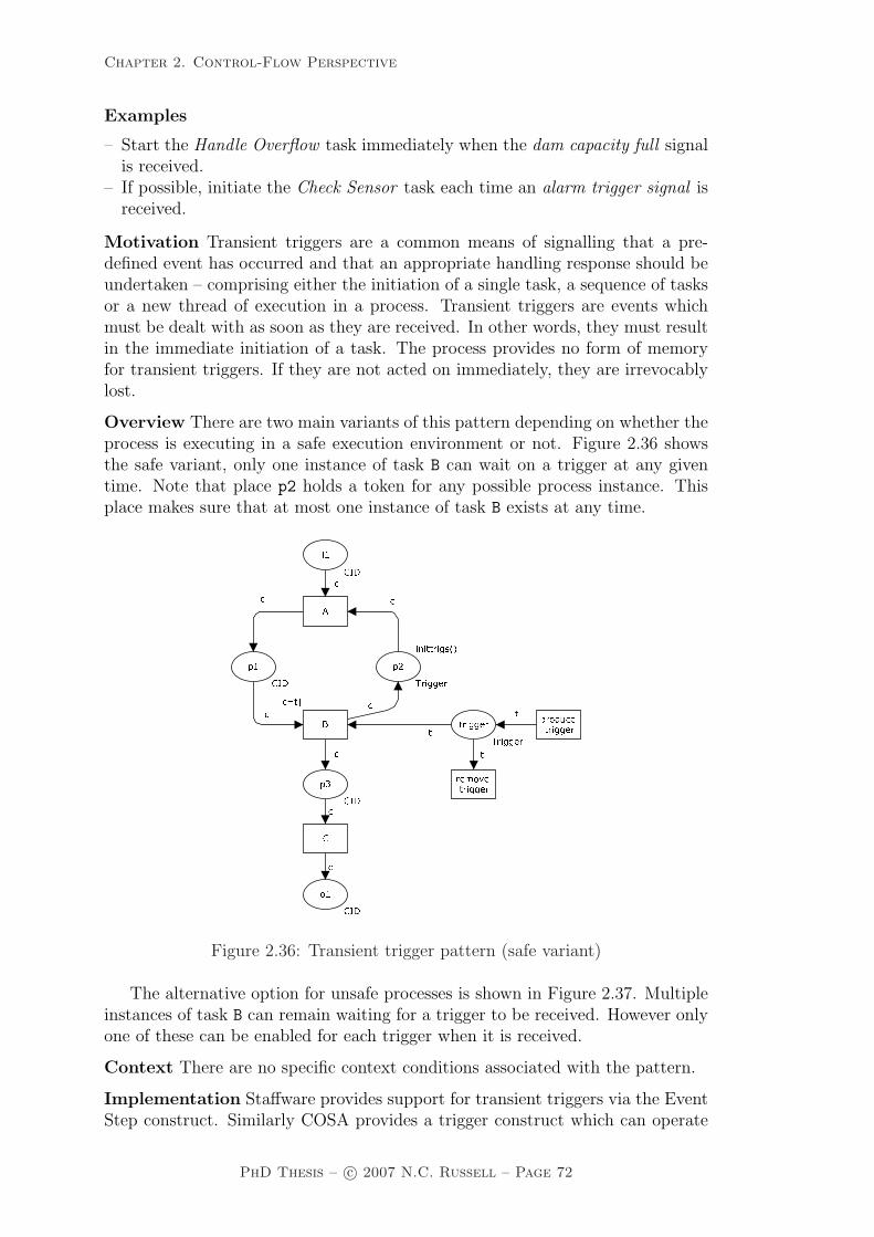
Chapter 2. Control-Flow Perspective
Examples
– Start the Handle Overflow task immediately when the dam capacity full signalis received.
– If possible, initiate the Check Sensor task each time an alarm trigger signal isreceived.
Motivation Transient triggers are a common means of signalling that a pre-defined event has occurred and that an appropriate handling response should beundertaken – comprising either the initiation of a single task, a sequence of tasksor a new thread of execution in a process. Transient triggers are events whichmust be dealt with as soon as they are received. In other words, they must resultin the immediate initiation of a task. The process provides no form of memoryfor transient triggers. If they are not acted on immediately, they are irrevocablylost.
Overview There are two main variants of this pattern depending on whether theprocess is executing in a safe execution environment or not. Figure 2.36 showsthe safe variant, only one instance of task B can wait on a trigger at any giventime. Note that place p2 holds a token for any possible process instance. Thisplace makes sure that at most one instance of task B exists at any time.
��� �����
�� �
��������� �� �������� �� � �����
�
�� ����� ��� � �� �� �� ��� ��� �� ��� �� ��� ���� ���
Figure 2.36: Transient trigger pattern (safe variant)
The alternative option for unsafe processes is shown in Figure 2.37. Multipleinstances of task B can remain waiting for a trigger to be received. However onlyone of these can be enabled for each trigger when it is received.
Context There are no specific context conditions associated with the pattern.
Implementation Staffware provides support for transient triggers via the EventStep construct. Similarly COSA provides a trigger construct which can operate
PhD Thesis – c© 2007 N.C. Russell – Page 72

Chapter 2. Control-Flow Perspective
�������
� �
��������� �� �������� �� � �����
�
�� ����� ��� ��� �� �� ����� �����
Figure 2.37: Transient trigger pattern (unsafe variant)
in both synchronous and asynchronous mode supporting transient and persistenttriggers respectively. Both of these offerings implement the safe form of thepattern (as illustrated in Figure 2.36). SAP Workflow provides similar support viathe “wait for event” step construct. UML 2.0 ADs provide the ability for signalsto be discarded where there are not immediately required through the explicitenablement feature of the AcceptEventAction construct which is responsible forhandling incoming signals.
Issues One consideration that arises with the use of transient triggers is whathappens when multiple triggers are received simultaneously or in a very short timeinterval. Are the latter triggers inherently lost as a trigger instance is alreadypending or are all instances preserved (albeit for a potentially short timeframe)?
Solutions In general, in the implementations examined (Staffware, COSA andSAP Workflow) it seems that all transient triggers are lost if they are not imme-diately consumed. There is no provision for transient triggers to be duplicated.
Evaluation Criteria An offering achieves full support if it provides a constructthat satisfies the description for the pattern.
Pattern WCP-24 (Persistent Trigger)
Description The ability for a task instance to be triggered by a signal fromanother part of the process or from the external environment. These triggers arepersistent in form and are retained by the process until they can be acted on bythe receiving task.
Examples
– Initiate the Staff Induction task each time a new staff member event occurs.
PhD Thesis – c© 2007 N.C. Russell – Page 73
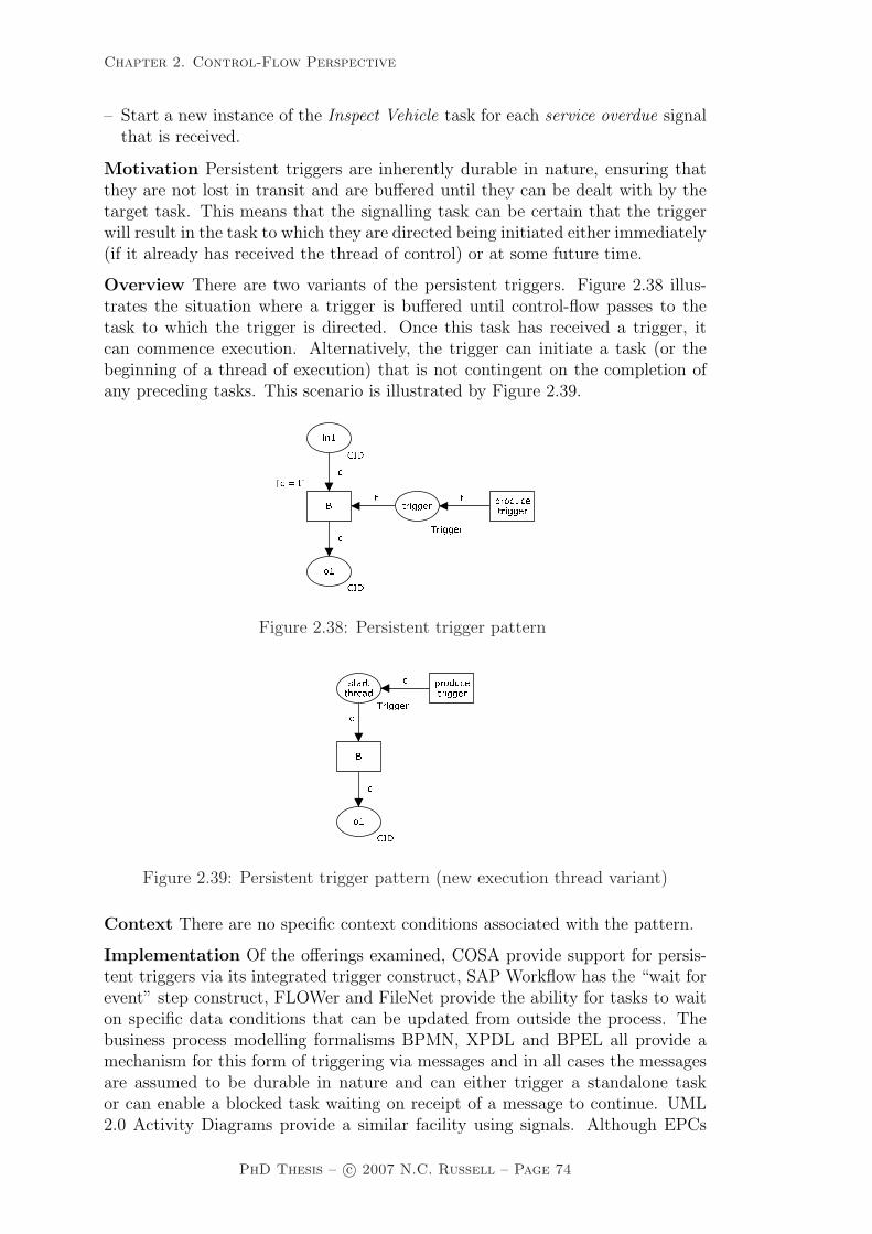
Chapter 2. Control-Flow Perspective
– Start a new instance of the Inspect Vehicle task for each service overdue signalthat is received.
Motivation Persistent triggers are inherently durable in nature, ensuring thatthey are not lost in transit and are buffered until they can be dealt with by thetarget task. This means that the signalling task can be certain that the triggerwill result in the task to which they are directed being initiated either immediately(if it already has received the thread of control) or at some future time.
Overview There are two variants of the persistent triggers. Figure 2.38 illus-trates the situation where a trigger is buffered until control-flow passes to thetask to which the trigger is directed. Once this task has received a trigger, itcan commence execution. Alternatively, the trigger can initiate a task (or thebeginning of a thread of execution) that is not contingent on the completion ofany preceding tasks. This scenario is illustrated by Figure 2.39.�� � ���� � �� ������ �� � ���� ���
�� ��� ��� � �� �� � �Figure 2.38: Persistent trigger pattern
�� �� �������� �� ��� � ���� �������� ��� �
Figure 2.39: Persistent trigger pattern (new execution thread variant)
Context There are no specific context conditions associated with the pattern.
Implementation Of the offerings examined, COSA provide support for persis-tent triggers via its integrated trigger construct, SAP Workflow has the “wait forevent” step construct, FLOWer and FileNet provide the ability for tasks to waiton specific data conditions that can be updated from outside the process. Thebusiness process modelling formalisms BPMN, XPDL and BPEL all provide amechanism for this form of triggering via messages and in all cases the messagesare assumed to be durable in nature and can either trigger a standalone taskor can enable a blocked task waiting on receipt of a message to continue. UML2.0 Activity Diagrams provide a similar facility using signals. Although EPCs
PhD Thesis – c© 2007 N.C. Russell – Page 74

Chapter 2. Control-Flow Perspective
provide support for multiple input events which can be utilized as persistent trig-gers, it is not possible to differentiate between them hence this is viewed as partialsupport. Note that if the pattern is not directly supported, it is often possible toimplement persistent triggers indirectly by adding a dummy task which “catches”the trigger.
Issues None identified.
Solutions N/A
Evaluation Criteria An offering achieves full support if it has a construct thatsatisfies the description for the pattern. If triggers do not retain a discrete identitywhen received and/or stored, an offering is viewed as providing partial support.
Next, some additional patterns related to cancellation are presented.
Pattern WCP-25 (Cancel Region)
Description The ability to disable a set of tasks in a process instance. If anyof the tasks are already executing (or are currently enabled), then they are with-drawn. The tasks need not be a connected subset of the overall process model.
Examples
– Stop any tasks in the Prosecution process which access the evidence databasefrom running.
– Withdraw all tasks in the Waybill Booking process after the freight-lodgementtask.
Motivation The option of being able to cancel a series of (potentially unrelated)tasks is a useful capability, particularly for handling unexpected errors or forimplementing forms of exception handling.
c
active
c
c
c
c
cc
regionstart
CID
start
t
tSKIP
c
t
cancelregion
Trigger
cancel
t’SKIP
t’
CID
normalend
endbypass
end
c
c
Figure 2.40: Cancel region implementation
Overview The general form of this pattern is illustrated in Figure 2.40. It isbased on the premise that every task in the required region has an alternate “by-pass” task. When the cancellation of the region is required, the process instance
PhD Thesis – c© 2007 N.C. Russell – Page 75

Chapter 2. Control-Flow Perspective
continues execution, but the bypass tasks are executed instead of the originaltasks. As a consequence, no further work occurs on the tasks in the cancellationregion. However, as shown for the Cancel Case (WCP-20) pattern, there areseveral alternative mechanisms that can be used to cancel parts of a process.
Context There are no specific context conditions associated with the pattern.
Implementation The concept of cancellation regions is not widely supported.Staffware offers the opportunity to withdraw steps but only if they have notalready commenced execution. FLOWer allows individual tasks to be skippedbut there is no means of cancelling a group of tasks. UML 2.0 Activity Diagramsare the only offering examined which provides complete support for this pattern:the InterruptibleActivityRegion construct allows a set of tasks to be cancelled.BPMN and XPDL offer partial support by enclosing the tasks that will potentiallybe cancelled in a subprocess and associating an error event with the subprocessto trigger cancellation when it is required. In both cases, the shortcoming of thisapproach is that the tasks in the subprocess must be a connected subgraph ofthe overall process model. Similarly BPEL only supports cancellation of tasksin the same scope hence it also achieves a partial rating as it is not possible tocancel an arbitrary group of tasks. As COSA has an integrated notion of state,it is possible to implement cancellation regions in a similar way to that presentedin Figure 2.40 however the overall process model is likely to become intractablefor cancellation regions of any reasonable scale hence this is viewed as partialsupport.
Issues One issue that can arise with the implementation of the Cancel Regionpattern occurs when the cancelling task lies within the cancellation region. Al-though this task must run to completion and cause the cancellation of all of thetasks in the defined cancellation region, once this has been completed, it too mustbe cancelled.
Solutions The most effective solution to this problem is to ensure that the can-celling task is the last of those to be processed (i.e. the last to be terminated)of the tasks in the cancellation region. The actual cancellation occurs when thetask to which the cancellation region is attached completes execution.
Evaluation Criteria An offering achieves full support if it provides a constructthat satisfies the description for the pattern. It rates as partial support if theprocess model must be changed in any way (e.g. use of subprocesses, inclusion ofbypass tasks) in order to accommodate cancellation regions.
Pattern WCP-26 (Cancel Multiple Instance Task)
Description Within a given process instance, multiple instances of a task canbe created. The required number of instances is known at design time. Theseinstances are independent of each other and run concurrently. At any time, themultiple instance task can be cancelled and any instances which have not com-pleted are withdrawn. Task instances that have already completed are unaffected.
Example
– Run 500 instances of the Protein Test task with distinct samples. If it has notcompleted one hour after commencement, cancel it.
PhD Thesis – c© 2007 N.C. Russell – Page 76

Chapter 2. Control-Flow Perspective
Motivation This pattern provides a means of cancelling a multiple instancetask at any time during its execution such that any remaining instances arecancelled. However any instances which have already completed are unaffectedby the cancellation.
Overview There are two variants of this pattern depending on whether the taskinstances are started sequentially or simultaneously. These scenarios are depictedin Figures 2.41 and 2.42. In both cases, transition C corresponds to the multipleinstance task, which is executed numinst times. When the cancel transition isenabled, any remaining instances of task C that have not already executed arewithdrawn, as is the ability to initiate any additional instances (via the create
instance transition). No subsequent tasks are enabled as a consequence of thecancellation.
���� �� ������������ �������
��
�� � �������������
����� ������� ������� ����������
� ����� ������ ������� �� ��� ! �"#
� ���� ���$"
Figure 2.41: Cancel multiple instance task pattern (sequential initiation)
�� �������� ��
��������
� ��� ���� �� ����
� ���� � �� ������������ ���������������������������������� ����� �������
�����������������
����� ������ ��������� � !
�" ��#�$ � ! �� ��#�% ��#�� ��#�� ��#&
Figure 2.42: Cancel multiple instance task pattern (concurrent initiation)
PhD Thesis – c© 2007 N.C. Russell – Page 77

Chapter 2. Control-Flow Perspective
Context There is one context condition associated with this pattern: it is as-sumed that only one instance of each multiple instance task is executing for agiven case at any time.
Implementation In order to implement this pattern, an offering also needs tosupport one of the Multiple Instance patterns that provide synchronization of thetask instances at completion (i.e. WCP-13 – WCP-15). Staffware provides theability to immediately terminate dynamic subprocedures albeit with loss of anyassociated data. SAP Workflow allows multiple instances created from a “multi-line container element” to be terminated when the parent task terminates. BPMNand XPDL support the pattern via a MI task which has an error type intermediateevent trigger at the boundary. When the MI task is to be cancelled, a cancel eventis triggered to terminate any remaining MI task instances. Similarly UML 2.0ADs provide support by including the multiple instance task in a cancellationregion. Oracle BPEL is able to support the pattern by associating a fault orcompensation handler with a <flowN> construct. As the <flowN> constructis specific to Oracle BPEL, there is no support for this pattern by BPEL moregenerally.
Issues None identified.
Solutions N/A.
Evaluation Criteria Full support for this pattern is demonstrated by any of-fering which provides a construct which satisfies the description when used in acontext satisfying the context assumption. If there are any limitations on therange of tasks that can appear within the cancellation region or the types of taskinstances that can be cancelled then an offering achieves a partial rating.
Pattern WCP-27 (Complete Multiple Instance Task)
Description Within a given process instance, multiple instances of a task canbe created. The required number of instances is known at design time. Theseinstances are independent of each other and run concurrently. It is necessaryto synchronize the instances at completion before any subsequent tasks can betriggered. During the course of execution, it is possible that the task needs tobe forcibly completed such that any remaining instances are withdrawn and thethread of control is passed to subsequent tasks.
Example
– Run 500 instances of the Protein Test task with distinct samples. One hourafter commencement, withdraw all remaining instances and initiate the nexttask.
Motivation This pattern provides a means of finalizing a multiple instance taskthat has not yet completed at any time during its execution such that any re-maining instances are withdrawn and the thread of control is immediately passedto subsequent tasks. Any instances which have already completed are unaffectedby the cancellation.
Overview There are two variants of this pattern depending on whether thetask instances are started sequentially or simultaneously. These scenarios are
PhD Thesis – c© 2007 N.C. Russell – Page 78
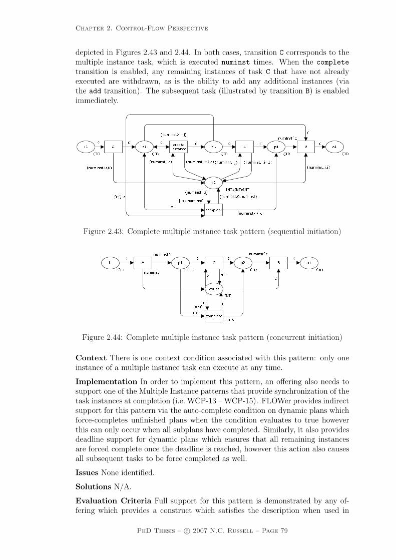
Chapter 2. Control-Flow Perspective
depicted in Figures 2.43 and 2.44. In both cases, transition C corresponds to themultiple instance task, which is executed numinst times. When the complete
transition is enabled, any remaining instances of task C that have not alreadyexecuted are withdrawn, as is the ability to add any additional instances (viathe add transition). The subsequent task (illustrated by transition B) is enabledimmediately.
���������������������������� ��������� �������������� ��� ��������� ������������ ��������������� ��������� ��� ��������� �����
��� � ��������
�
�������������������� ����������� ���������������
�� �� !�� !�� �" ��#�$ ��# �� ��#�� ��#�� ��#
Figure 2.43: Complete multiple instance task pattern (sequential initiation)
�� �������� ������
����������������� ��������
��� ���� ��� �� ����� ����� ����� ���Figure 2.44: Complete multiple instance task pattern (concurrent initiation)
Context There is one context condition associated with this pattern: only oneinstance of a multiple instance task can execute at any time.
Implementation In order to implement this pattern, an offering also needs tosupport one of the Multiple Instance patterns that provide synchronization of thetask instances at completion (i.e. WCP-13 – WCP-15). FLOWer provides indirectsupport for this pattern via the auto-complete condition on dynamic plans whichforce-completes unfinished plans when the condition evaluates to true howeverthis can only occur when all subplans have completed. Similarly, it also providesdeadline support for dynamic plans which ensures that all remaining instancesare forced complete once the deadline is reached, however this action also causesall subsequent tasks to be force completed as well.
Issues None identified.
Solutions N/A.
Evaluation Criteria Full support for this pattern is demonstrated by any of-fering which provides a construct which satisfies the description when used in
PhD Thesis – c© 2007 N.C. Russell – Page 79

Chapter 2. Control-Flow Perspective
a context satisfying the context assumption. It demonstrates partial support ifthere are limitations on when the completion task can be initiated or if the forcecompletion of the remaining instances does not result in subsequent tasks in theprocess instance being triggered normally.
The Structured Discriminator (WCP-9) pattern is assumed to operate in a safecontext and waits for the completion of all branches before it resets. Therefore,two extensions of the basic pattern are proposed which relax some of these contextassumptions and allow it to operate in different scenarios. These variants are theBlocking Discriminator and the Cancelling Discriminator.
Pattern WCP-28 (Blocking Discriminator)
Description The convergence of two or more branches into a single subsequentbranch following one or more corresponding divergences earlier in the processmodel. The thread of control is passed to the subsequent branch when the firstactive incoming branch has been enabled. The Blocking Discriminator constructresets when all active incoming branches have been enabled once for the sameprocess instance. Subsequent enablements of incoming branches are blocked untilthe Blocking Discriminator has reset.
Example
– The check credentials task can commence once the confirm delegation arrivalor the security check task has been completed. Although these two tasks canexecute concurrently, in practice, the confirm delegation arrival task alwayscompletes before security check task. Another instance of the check credentialstask cannot be initiated if a preceding instance of the task has not yet com-pleted. Similarly, subsequent instances of the confirm delegation arrival andthe security check tasks cannot be initiated if a preceding instance of the checkcredentials task has not yet completed.
Motivation The Blocking Discriminator pattern is a variant of the StructuredDiscriminator pattern that is able to run in environments where there are po-tentially several concurrent execution threads within the same process instance.This quality allows it to be used in loops and other process structures where morethan one execution thread may be received in a given branch in the time betweenthe first branch being enabled and the Blocking Discriminator being reset.
Overview Figure 2.45 illustrates the operation of this pattern. It is more robustthan the Structured Discriminator as it is not subject to the constraint thateach incoming branch can only being triggered once prior to reset. The BlockingDiscriminator functions by keeping track of which inputs have been triggered(via the triggered input place) and preventing them from being re-enableduntil the construct has reset as a consequence of receiving a trigger on eachincoming branch. An important feature of this pattern is that it is able to beutilized in environments that do not support a safe process model or those thatmay receive multiple triggerings on the same input place e.g. where the BlockingDiscriminator is used within a loop.
Context There are no specific context conditions associated with the pattern.
PhD Thesis – c© 2007 N.C. Russell – Page 80

Chapter 2. Control-Flow Perspective
������� �� ��������� ��
�� ���� ������ � ���� ���
���� ��� �� ������������ � �� �� ��������
������
����
�� ����� ��� ������ �������� ������� � ����� ������ �� ���
�� ���� ����� ���
Figure 2.45: Blocking discriminator pattern
Implementation In the event of concurrent process instances attempting tosimultaneously initiate the same Blocking Discriminator, it is necessary to keeptrack of both the process instance and the input branches that have triggeredthe Blocking Discriminator and also the execution threads that are consequentlyblocked (including the number of distinct triggerings on each branch) until itcompletes. The Blocking Discriminator is partially supported by BPMN, XPDLand UML 2.0 ADs.
Issues None identified.
Solutions N/A.
Evaluation Criteria An offering achieves full support if it provides a constructthat satisfies the description for the pattern. If there is any ambiguity in how thejoin condition is specified, an offering is considered to provide partial support forthe pattern.
Pattern WCP-29 (Cancelling Discriminator)
Description The convergence of two or more branches into a single subsequentbranch following one or more corresponding divergences earlier in the processmodel. The thread of control is passed to the subsequent branch when the firstactive incoming branch has been enabled. Triggering the Cancelling Discrimina-tor also cancels the execution of all of the other incoming branches and resetsthe construct.
Example
– After the extract-sample task has completed, parts of the sample are sent tothree distinct laboratories for examination. Once the first of these laboratoriescompletes the sample-analysis, the other two task instances are cancelled andthe review-drilling task commences.
Motivation This pattern provides a means of expediting a process instance wherea series of incoming branches to a join need to be synchronized but it is notimportant that the tasks associated with each of the branches (other than thefirst of them) be completed.
PhD Thesis – c© 2007 N.C. Russell – Page 81

Chapter 2. Control-Flow Perspective
Overview The operation of this pattern is shown in Figure 2.46. Inputs i1
to im to the Cancelling Discriminator serve to identify the branches precedingthe construct. Transitions A1 to Am signify tasks in these preceding branches.Transitions S1 to Sm indicate alternate “bypass” or “cancellation” tasks for eachof these branches (these execution options are not initially available to incomingexecution threads). The first control-flow token for a given case received at anyinput will cause B to fire and put a token in o1. As soon as this occurs, subsequentexecution threads on other branches are put into “bypass mode” and instead ofexecuting the normal tasks (A1..Am) on their specific branch, they can execute the“bypass” transitions (S1..Sm). (Note that the bypass transitions do not requireany interaction. Hence they are executed directly by the PAIS and it can assumedthat the skip transitions are executed once they are enabled and complete almostinstantaneously hence expediting completion of the branch). Once all incomingbranches for a given case have been completed, the Cancelling Discriminatorconstruct can then reset and be re-enabled again for the same case.
���� �
� ����
���� �������� � ��������
��
��
��� �
� �� ����� ������ �� ����� ����� ���
�� ���
Figure 2.46: Cancelling discriminator pattern
Context There is one context condition associated with the use of this pattern:once the Cancelling Discriminator has been activated and has not yet been reset,it is not possible for another signal to be received on the activated branch or formultiple signals to be received on any incoming branch. In other words, all inputplaces to the Cancelling Discriminator (i.e. i1 to im) are safe .
Implementation In order to implement this pattern, it is necessary for the of-fering to support some means of denoting the extent of the incoming branches tobe cancelled. This can be based on the Cancel Region pattern although supportis only required for a restricted form of the pattern as the region to be cancelledwill always be a connected subgraph of the overall process model with the Can-celling Discriminator construct being the connection point for all of the incomingbranches.
This pattern is supported by the fork construct in SAP Workflow with thenumber of branches required for completion set to one. In BPMN it is achievedby incorporating the incoming branches and the Cancelling Discriminator in a
PhD Thesis – c© 2007 N.C. Russell – Page 82

Chapter 2. Control-Flow Perspective
subprocess that has an error event associated with it. The error event is trig-gered, cancelling the remaining branches in the subprocess, when the CancellingDiscriminator is triggered by the first incoming branch. This configuration is il-lustrated in Figure 2.47(a). A similar solution is available in XPDL. UML 2.0 ADssupport the pattern in a similar way by enclosing all of the incoming branches inan InterruptibleActivityRegion which is cancelled when the Cancelling Discrim-inator fires.
a) BPMN implementation
1st branch complete
1
n
A
A
B
1
n
A
A
B
b) UML 2.0 ADs implementation
1st branch complete
Figure 2.47: Cancelling discriminator pattern in BPMN and UML 2.0 ADs
Issues The major difficulty with this pattern is in determining how much of theprocess model preceding the Cancelling Discriminator is to be included in thecancellation region.
Solutions This issue is easily addressed in structured processes as all of thebranches back to the preceding split construct which corresponds to the Can-celling Discriminator should be subject to cancellation. In Figure 2.48(a), it iseasy to see that the area denoted by the dotted box should be the cancellationregion. It is a more complex matter when the process is not structured (e.g. asin Figure 2.48(b)) or other input arcs exist into the preceding branches to theCancelling Discriminator that are not related to the corresponding split as shownin Figure 2.48(c). In both of these situations, the overall structure of the processleading up to the Cancelling Discriminator serves as a determinant of whetherthe pattern can be supported or not. In Figure 2.48(b), a cancellation region canbe conceived which reaches back to the first AND-split and the pattern can beimplemented based on this. A formal approach to determining the scope of thecancellation region can be found elsewhere [Aal01]. In Figure 2.48(c), the po-tential for other control-flows to be introduced which do not relate to the earlierAND-split, means that the pattern probably cannot be supported in a processmodel of this form.
Evaluation Criteria Full support for this pattern is demonstrated by any of-fering which provides a construct which satisfies the description when used in acontext satisfying the context assumption. An offering is considered to providepartial support for the pattern if there are side-effects associated with the exe-cution of the pattern (e.g. tasks in incoming branches which have not completedbeing recorded as complete).
As discussed before, the Partial Join can be seen as a generalization of the Dis-criminator pattern (i.e. a 1-out-of-m join). Hence, some patterns are introducedwhich generalize the different variants of the Discriminator pattern (where thenumber of incoming threads required for the join to fire (n) is greater than 1).
PhD Thesis – c© 2007 N.C. Russell – Page 83

Chapter 2. Control-Flow Perspective
b)
H
C
ED
F
B
G
AND
AND
DISCA
OR
DISCA
C
ED
F
B
G
HAND
H
C
ED
F
B
G
ANDA
AND
DISC
a)
c)
Figure 2.48: Process structure considerations for cancelling discriminator
Pattern WCP-30 (Structured Partial Join)
Description The convergence of two or more branches (say m) into a singlesubsequent branch following a corresponding divergence earlier in the processmodel such that the thread of control is passed to the subsequent branch when n
of the incoming branches have been enabled where n is less than m. Subsequentenablements of incoming branches do not result in the thread of control beingpassed on. The join construct resets when all active incoming branches havebeen enabled. The join occurs in a structured context, i.e. there must be asingle Parallel Split construct earlier in the process model with which the joinis associated and it must merge all of the branches emanating from the ParallelSplit. These branches must either flow from the Parallel Split to the join withoutany splits or joins or be structured in form (i.e. balanced splits and joins).
Example
– Once two of the preceding three Expenditure Approval tasks have completed,start the Issue Cheque task. Wait until the remaining task has completedbefore allowing the Issue Cheque task to fire again.
Motivation The Structured Partial Join pattern provides a means of mergingtwo or more distinct branches resulting from a specific Parallel Split or AND-split construct earlier in a process into a single branch. The join construct doesnot require triggers on all incoming branches before it can fire. Instead a given
PhD Thesis – c© 2007 N.C. Russell – Page 84

Chapter 2. Control-Flow Perspective
threshold can be defined which describes the circumstances under which the joinshould fire – typically this is presented as the ratio of incoming branches thatneed to be live for firing as against the total number of incoming branches to thejoin, e.g. a 2-out-of-3 join signifies that the join construct should fire when two ofthree incoming arcs are live. Subsequent completions of other remaining incomingbranches have no effect on (and do not trigger) the subsequent branch. As such,the Structured Partial Join provides a mechanism for progressing the executionof a process once a specified number of concurrent tasks have completed ratherthan waiting for all of them to complete.
Overview The Structured Partial Join pattern is one possible variant of theAND-Join construct where the number of incoming arcs that will cause the jointo fire (n) is between 2 and m - 1 (i.e. the total number of incoming branches lessone, i.e. 2≤n<m). There are a number of possible specializations of the AND-join pattern and they form a hierarchy based on the value of n. Where onlyone incoming arc must be live for firing (i.e. n=1), this corresponds to one ofthe variants of the Discriminator pattern (cf. WCP-9, WCP-28 and WCP-29).An AND-Join where all incoming arcs are considered (i.e. n=m) is either theSynchronization (WCP-3) or Generalized AND-Join pattern (WCP-33).
The pattern provides a means of merging two or more branches in a processand progressing execution of the process as rapidly as possible by enabling thesubsequent (merged) branch as soon as a thread of control has been received onn of the incoming branches where n is less than the total number of incomingbranches. The semantics of the Structured Partial Join pattern are illustrated inFigure 2.49. Note that B requires n tokens in place p1 to progress.�
� �� ��� ��������� ��� ������
��� �� ����� ��� �� ���
�� ����� ��� �� �� ���Figure 2.49: Structured partial join pattern
Context There are two context conditions associated with the use of this pattern:(1) once the Structured Partial Join has been activated and has not yet beenreset, it is not possible for another signal to be received on the activated branchor for multiple signals to be received on any incoming branch. In other words,all input places to the Structured Partial Join (i.e. i1 to im) are safe and (2)once the associated Parallel Split has been enabled none of the tasks in thebranches leading to the Structured Partial Join can be cancelled before it hasbeen triggered. The only exception to this is that it is possible for all of the tasksleading up to the Structured Partial Join to be cancelled.
PhD Thesis – c© 2007 N.C. Russell – Page 85

Chapter 2. Control-Flow Perspective
There are two possible variants on this pattern that arise from relaxing some ofthe context conditions associated with it. Both of these improve on the efficiencyof the join whilst retaining its overall behaviour. The first alternative, the Block-ing Partial Join (WCP-31) removes the requirement that each incoming branchcan only be enabled once between join resets. It allows each incoming branch tobe triggered multiple times although the construct only resets when one trigger-ing has been received on each input branch. It is illustrated in Figure 2.50 anddiscussed in detail on page 86. Second, the Cancelling Partial Join (WCP-32),improves the efficiency of the pattern further by cancelling the other incomingbranches to the join construct once n incoming branches have completed. It isillustrated in Figure 2.51 and discussed in further detail on page 88.
Implementation One of the difficulties in implementing the Structured PartialJoin is that it essentially requires a specific construct to represent the join if it is tobe done in a tractable manner. iPlanet does so via the router construct which linkspreceding tasks to a target task. A router can have a custom trigger conditionspecified for it that causes the target task to trigger when n incoming branches arelive. SAP Workflow provides partial support for this pattern via the fork constructalthough any unfinished branches are cancelled once the first completes. None ofthe other offerings examined offers a dedicated construct. Staffware provides fora 1-out-of-2 join, but more complex joins must be constructed from this resultingin an over-complex process model. Similar difficulties exist for COSA. Of thebusiness process modelling languages, both BPMN and XPDL appear to providesupport for the Structured Partial Join via the complex gateway construct butthe lack of detail on how the IncomingCondition is specified results in a partialrating. UML 2.0 ADs also suffers from a similar lack of detail on the JoinSpecconfiguration required to support this pattern. There is no ability to representthe construct in BPEL.
Issues None identified.
Solutions N/A.
Evaluation Criteria Full support for this pattern is demonstrated by any of-fering which provides a construct which satisfies the description when used in acontext satisfying the context assumptions. If there is any ambiguity in how thejoin condition is specified, an offering is considered to provide partial support forthe pattern.
Pattern WCP-31 (Blocking Partial Join)
Description The convergence of two or more branches (say m) into a singlesubsequent branch following one or more corresponding divergences earlier in theprocess model. The thread of control is passed to the subsequent branch when n
of the incoming branches have been enabled (where 2≤n<m). The join constructresets when all active incoming branches have been enabled once for the sameprocess instance. Subsequent enablements of incoming branches are blocked untilthe join has reset.
Example
– When the first member of the visiting delegation arrives, the check credentialstask can commence. It concludes when either the ambassador or the president
PhD Thesis – c© 2007 N.C. Russell – Page 86

Chapter 2. Control-Flow Perspective
arrives. Owing to staff constraints, only one instance of the check credentialstask can be undertaken at any time. Should members of another delegationarrive, the checking of their credentials is delayed until the first check credentialstask has completed.
Motivation The Blocking Partial Join is a variant of the Structured Partial Jointhat is able to run in environments where there are concurrent process instances,particularly process instances that have multiple concurrent execution threads.
Overview Figure 2.50 illustrates the operation of this pattern. The BlockingPartial Join functions by keeping track of which inputs have been enabled (viathe triggered input place) and preventing them from being re-enabled untilthe construct has reset as a consequence of receiving a trigger on each incomingplace. After n incoming triggers have been received for a given process instance(via tokens being received in n distinct input places from i1 to im), the join firesand a token is placed in output o1. The completion of the remaining n-m brancheshas no impact on the join except that it is reset when the last of them is received.
The pattern shares the same advantages over the Structured Partial Joinas the Blocking Discriminator does over the Structured Discriminator, namelygreater flexibility as it is able to deal with the situation where a branch is trig-gered more than once, e.g. where the construct exists within a loop.
������� �� ��������� ��
�� ���� ������ � ���� ���
��� ��� �� ����������� � �� �� ��������
������
����
�� ����� ��� ������ ������� ������ � ����� ����� �� ���
�� ���� ����� ���
Figure 2.50: Blocking partial join pattern
Context There are no specific context conditions associated with the pattern.
Implementation The approach to implementing this pattern is essentially thesame as that for the Blocking Discriminator except that the join fires when n
incoming branches have triggered rather than just the first. The Blocking PartialJoin is partially supported by BPMN, XPDL and UML 2.0 ADs as it is unclearhow the join condition is specified.
Issues None identified.
Solutions N/A.
Evaluation Criteria An offering achieves full support if it provides a constructthat satisfies the description for the pattern. If there is any ambiguity in how thejoin condition is specified, an offering is considered to provide partial support forthe pattern.
PhD Thesis – c© 2007 N.C. Russell – Page 87

Chapter 2. Control-Flow Perspective
Pattern WCP-32 (Cancelling Partial Join)
Description The convergence of two or more branches (say m) into a singlesubsequent branch following one or more corresponding divergences earlier in theprocess model. The thread of control is passed to the subsequent branch when n
of the incoming branches have been enabled where n is less than m. Triggering thejoin also cancels the execution of all of the other incoming branches and resetsthe construct.
Example
– Once the picture is received, it is sent to three art dealers for the examina-tion. Once two of the prepare condition report tasks have been completed, theremaining prepare condition report task is cancelled and the plan restorationtask commences.
Motivation This pattern provides a means of expediting a process instance wherea series of incoming branches to a join need to be synchronized but only a subsetof those tasks associated with each of the branches needs to be completed.
Overview The operation of this pattern is shown in Figure 2.51. It operatesin the same way as the Cancelling Discriminator except that, for this pattern,the cancellation is only triggered when n distinct incoming branches have beenenabled.
���� �
�����
�� �������� � ��������
��
��
�� ��
�� �� ����� ������ �� ����� ����� ���
�� �����
Figure 2.51: Cancelling partial join pattern
Context There is one context condition associated with the use of this pattern:once the Cancelling Partial Join has been activated and has not yet been reset,it is not possible for another signal to be received on the activated branch or formultiple signals to be received on any incoming branch. In other words, all inputplaces to the Cancelling Partial Join (i.e. i1 to im) are safe .
Implementation The approach to implementing this pattern is essentially thesame as that for the Cancelling Discriminator except that the join fires whenn incoming branches have triggered rather than just the first. The CancellingPartial Join is supported by SAP Workflow and UML 2.0 ADs. BPMN and
PhD Thesis – c© 2007 N.C. Russell – Page 88

Chapter 2. Control-Flow Perspective
XPDL achieve a partial support rating as it is unclear exactly how the joincondition is specified.
Issues As for the Cancelling Discriminator pattern.
Solutions As for the Cancelling Discriminator pattern.
Evaluation Criteria Full support for this pattern is demonstrated by any of-fering which provides a construct which satisfies the description when used in acontext satisfying the context assumption. An offering is considered to providepartial support for the pattern if there are undesirable side-effects associated withthe construct firing (e.g. tasks in incoming branches which have not completedbeing recorded as complete) or if the semantics associated with the join conditionare unclear.
Many of the advanced synchronization patterns assume a safe context (i.e. a placecannot be marked twice for the same process instance). The following pattern isnot predicated on this assumption and corresponds exactly to a transition in anon-safe Petri net.
Pattern WCP-33 (Generalized AND-Join)
Description The convergence of two or more branches into a single subsequentbranch such that the thread of control is passed to the subsequent branch whenall input branches have been enabled. Additional triggers received on one ormore branches between firings of the join persist and are retained for futurefirings. Over time, each of the incoming branches should deliver the same numberof triggers to the AND-join construct (although obviously, the timing of thesetriggers may vary).
Examples
– When all Get Directors Signature tasks have completed, run the CompleteContract task.
– Accumulate engine, chassis and body components from the various productionlines. When one of each has been received, use one of each component toassemble the basic car.
Motivation The Generalized AND-Join corresponds to one of the generally ac-cepted notions of an AND-join implementation (the other situation is describedby the Synchronization pattern) in which several paths of execution are synchro-nized and merged together. Unlike the Synchronization pattern, it supports thesituation where one or more incoming branches may receive multiple triggers forthe same process instance (i.e. a non-safe context) before the join resets. Theclassical Petri net uses semantics close to this pattern. This shows that this se-mantics can be formulated easily. However, the intended semantics in practicetends to be unclear in situations involving non-safe behaviour.
Overview The operation of the Generalized AND-Join is illustrated in Figure2.52. Before transition A can be enabled, an input token (corresponding to thesame case) is required in each of the incoming places (i.e. i1 to i3). When thereare corresponding tokens in each place, transition A is enabled and consumes atoken from each input place and once it has completed, deposits a token in output
PhD Thesis – c© 2007 N.C. Russell – Page 89
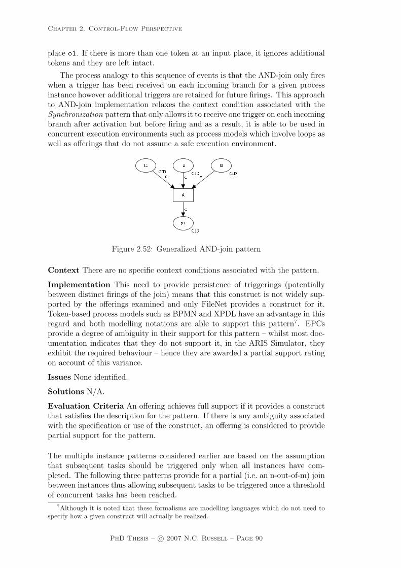
Chapter 2. Control-Flow Perspective
place o1. If there is more than one token at an input place, it ignores additionaltokens and they are left intact.
The process analogy to this sequence of events is that the AND-join only fireswhen a trigger has been received on each incoming branch for a given processinstance however additional triggers are retained for future firings. This approachto AND-join implementation relaxes the context condition associated with theSynchronization pattern that only allows it to receive one trigger on each incomingbranch after activation but before firing and as a result, it is able to be used inconcurrent execution environments such as process models which involve loops aswell as offerings that do not assume a safe execution environment.� � ���
�� ��� �� ��� �� ���� ���
Figure 2.52: Generalized AND-join pattern
Context There are no specific context conditions associated with the pattern.
Implementation This need to provide persistence of triggerings (potentiallybetween distinct firings of the join) means that this construct is not widely sup-ported by the offerings examined and only FileNet provides a construct for it.Token-based process models such as BPMN and XPDL have an advantage in thisregard and both modelling notations are able to support this pattern7. EPCsprovide a degree of ambiguity in their support for this pattern – whilst most doc-umentation indicates that they do not support it, in the ARIS Simulator, theyexhibit the required behaviour – hence they are awarded a partial support ratingon account of this variance.
Issues None identified.
Solutions N/A.
Evaluation Criteria An offering achieves full support if it provides a constructthat satisfies the description for the pattern. If there is any ambiguity associatedwith the specification or use of the construct, an offering is considered to providepartial support for the pattern.
The multiple instance patterns considered earlier are based on the assumptionthat subsequent tasks should be triggered only when all instances have com-pleted. The following three patterns provide for a partial (i.e. an n-out-of-m) joinbetween instances thus allowing subsequent tasks to be triggered once a thresholdof concurrent tasks has been reached.
7Although it is noted that these formalisms are modelling languages which do not need tospecify how a given construct will actually be realized.
PhD Thesis – c© 2007 N.C. Russell – Page 90

Chapter 2. Control-Flow Perspective
Pattern WCP-34 (Static Partial Join for Multiple Instances)
Description Within a given process instance, multiple concurrent instances ofa task (say m) can be created. The required number of instances is known whenthe first task instance commences. Once n of the task instances have completed(where n is less than m), the next task in the process is triggered. Subsequent com-pletions of the remaining m-n instances are inconsequential, however all instancesmust have completed in order for the join construct to reset and be subsequentlyre-enabled.
Example
– Examine 10 samples from the production line for defects. Continue with thenext task when 7 of these examinations have been completed.
Motivation The Static Partial Join for Multiple Instances pattern is an exten-sion to the Multiple Instances with a priori Runtime Knowledge pattern whichallows the process instance to continue once a given number of the task instanceshave completed rather than requiring all of them to finish before the subsequenttask can be triggered.
Overview The general format of the Static Partial Join for Multiple Instancespattern is illustrated in Figure 2.53. Transition A corresponds to the multipleinstance task. In terms of the operation of this pattern, once the input placei1 is triggered for a case, m instances of the multi-instance task A are initiatedconcurrently and an “active” status is recorded for the pattern. These instancesproceed independently and once n of them have completed, the join can be trig-gered and a token placed in output place o1 signalling that the thread of controlcan be passed to subsequent tasks in the process model. Simultaneously with thejoin firing, the token is removed from the active place allowing the remaining n
- m tasks to complete. Once all m instances of task A have finished, the status ofthe pattern changes to “ready” allowing it to be re-enabled.
����������������� �����
�� ����������� ����������
������ � ��������� �� �������� ������ �� ����� ��� �� ���� � ����
��� ��� ��
����! ��������� ���� ��"��� ������# �� $ �� # �� �# �� �
Figure 2.53: Static partial join implementation for multiple instances
There are two variants of this pattern which relax some of the restrictionsassociated with the form of the pattern described above. First, the CancellingPartial Join for Multiple Instances pattern removes the need to wait for all of the
PhD Thesis – c© 2007 N.C. Russell – Page 91

Chapter 2. Control-Flow Perspective
task instances to complete by cancelling any remaining task instances as soon asthe join fires. It is illustrated in Figure 2.54 and discussed further on page 92.
The second, the Dynamic Partial Join for Multiple Instances pattern allowsthe value of m (i.e. the number of instances) to be determined during the executionof the task instances. In particular, it allows additional task instances to becreated “on the fly”. This pattern is illustrated in Figure 2.55 and described infurther detail on page 93.
Context There are two context conditions associated with this pattern: (1) thenumber of concurrent task instances (denoted by variable m in Figure 2.53) isknown prior to task commencement and (2) the number of tasks that need to becompleted before subsequent tasks in the process model can be triggered (denotedby variable n in Figure 2.53) is also known prior to task commencement.
Implementation BPMN and XPDL both appear to offer support for this patternvia the Multiple Instance Loop Activity construct where the MI Flow Conditionattribute is set to complex and ComplexMI FlowCondition is an expression thatevaluates to true when exactly n instances have completed causing a single tokento be passed on to the following task. However no detail is provided to explain howthe ComplexMI FlowCondition is specified hence this is considered to constitutepartial support for the pattern.
Issues None identified.
Solutions N/A.
Evaluation Criteria An offering achieves full support if it provides a constructthat satisfies the description and context criteria for the pattern. It achievespartial support if there is any ambiguity associated with the specification of thejoin condition.
Pattern WCP-35 (Cancelling Partial Join for Multiple Instances)
Description Within a given process instance, multiple concurrent instances ofa task (say m) can be created. The required number of instances is known whenthe first task instance commences. Once n of the task instances have completed(where n is less than m), the next task in the process is triggered and the remainingm−n instances are cancelled.
Example
– Run 500 instances of the Protein Test task with distinct samples. Once 400have completed, cancel the remaining instances and initiate the next task.
Motivation This pattern is a variant of the Multiple Instances with a prioriRuntime Knowledge pattern that expedites process throughput by both allowingthe process to continue to the next task once a specified number (n) of the multipleinstance tasks have completed and also cancels any remaining task instancesnegating the need to expend any further effort executing them.
Overview Figure 2.54 illustrates the operation of this pattern. It is similar inform to that for the Static Partial Join for Multiple Instances pattern (WCP-34) but functions in a different way once the join has fired. At this point any
PhD Thesis – c© 2007 N.C. Russell – Page 92

Chapter 2. Control-Flow Perspective
remaining instances which have not already commenced are “bypassed” by al-lowing the skip task to execute in their place. The skip task executes almostinstantaneously for those and the pattern is almost immediately able to reset.
������ �� ����������������� �������
������������ ���������� �� ���� ���
�� �������� �� �������� ����� �� ����� ��� �� ���� �� ������� �� �!
����" ������� �� �! ��#��� � �����$ �!�% �!�$ �!$ �!
Figure 2.54: Cancelling partial join implementation for multiple instances
Context This pattern the same context conditions as the Static Partial Join forMultiple Instances pattern: (1) the number of concurrent task instances (denotedby variable m in Figure 2.53) is known prior to task commencement and (2) thenumber of tasks that need to complete before subsequent tasks in the processmodel can be triggered (denoted by variable n in Figure 2.53) is known prior totask commencement.
Implementation This pattern relies on the availability of a Cancel Task orCancel Region capability within an offering and at least one of these patternsneeds to be supported for this pattern to be facilitated. As for WCP-34, bothBPMN and XPDL appear to offer support for this pattern by associating an errortype intermediate trigger with the multiple instance task. Immediately followingthis task is a task that issues a cancel event effectively terminating any remainingtask instances once the first n of them have completed. However it is unclear howthe ComplexMI FlowCondition should be specified to allow the cancellation tobe triggered once n task instances have completed.
Issues None identified.
Solutions N/A.
Evaluation Criteria Full support for this pattern is demonstrated by any of-fering which provides a construct which satisfies the description when used in acontext satisfying the context assumption. An offering achieves partial supportif there is any ambiguity associated with the implementation of the pattern (e.g.if it is unclear how the join condition is specified).
Pattern WCP-36 (Dynamic Partial Join for Multiple Instances)
Description Within a given process instance, multiple concurrent instances of atask can be created. The required number of instances may depend on a numberof runtime factors, including state data, resource availability and inter-processcommunications and is not known until the final instance has completed. At
PhD Thesis – c© 2007 N.C. Russell – Page 93

Chapter 2. Control-Flow Perspective
any time, whilst instances are running, it is possible for additional instances tobe initiated providing the ability to do so has not been disabled. A completioncondition is specified which is evaluated each time an instance of the task com-pletes. Once the completion condition evaluates to true, the next task in theprocess is triggered. Subsequent completions of the remaining task instances areinconsequential and no new instances can be created.
Example
– The despatch of an oil rig from factory to site involves numerous transport ship-ment tasks. These occur concurrently and although sufficient tasks are startedto cover initial estimates of the required transport volumes, it is always possi-ble for additional tasks to be initiated if there is a shortfall in transportationrequirements. Once 90% of the transport shipment tasks are complete, thenext task (invoice transport costs) can commence. The remaining transportshipment tasks continue until the whole rig has been transported.
Motivation This pattern is a variant of the Multiple Instances without a prioriRuntime Knowledge pattern that provides the ability to trigger the next taskonce a nominated completion condition is satisfied.
Overview Figure 2.55 illustrates the operation of this pattern. The multipleinstance task is illustrated by transition A. At commencement, the number ofinstances initially required is indicated by variable m. Additional instances may beadded to this at any time via the start instance transition. At commencement,the pattern is in the active state. Once enough instances of task A have completedand the join transition has fired, the next task is enabled (illustrated via a tokenbeing placed in the output place o1) and the remaining instances of task A run tocompletion before the complete transition is enabled. No new instances can becreated at this time. Finally when all instances of A have completed, the patternresets and can be re-enabled. An important feature of the pattern is the abilityto disable further creation of task instances at any time after the first instanceshave been created.
����� ����� ����������
� ��������������� ��������
� ����������� �� ���� ��
� ��������������� ���� ������ ������������������ ��������
�� ��������� ��� ��������� ������ �� ����� ���� �� ����� ���� ������������ �� �!""#
�$ �%&'��� �(� ��
����) ��������� ���� ������ ��%&'� �� �* �� � �� � ��
���� �������+� �������� ����
�����Figure 2.55: Dynamic partial join implementation for multiple instances
PhD Thesis – c© 2007 N.C. Russell – Page 94

Chapter 2. Control-Flow Perspective
Context This pattern has two context conditions: (1) the number of concurrenttask instances to be started initially (denoted by variable m in Figure 2.53) isknown prior to task commencement and (2) it must be possible to access anydata elements or other necessary resources required to evaluate the completioncondition at the conclusion of each task instance.
Implementation Of the offerings identified, only FLOWer provides support forthe dynamic creation of multiple instance tasks (via dynamic subplans), howeverit requires all of them to be completed before any completion conditions associatedwith a dynamic subplan (e.g. partial joins) can be evaluated and subsequent taskscan be triggered. This is not considered to constitute support for this pattern.
Issues None identified.
Solutions N/A.
Evaluation Criteria Full support for this pattern is demonstrated by any of-fering which provides a construct which satisfies the description when used ina context satisfying the context assumptions. It achieves partial support if thecreation of task instances cannot be disabled once the first task instance hascommenced.
When defining the Structured Synchronizing Merge pattern (WCP-7), severalcontext assumptions were made. Now some of these assumptions are relaxedresulting in additional patterns.
Pattern WCP-37 (Local Synchronizing Merge)
Description The convergence of two or more branches which diverged earlierin the process into a single subsequent branch such that the thread of controlis passed to the subsequent branch when each active incoming branch has beenenabled. Determination of how many branches require synchronization is madeon the basis of information locally available to the merge construct. This maybe communicated directly to the merge by the preceding diverging construct oralternatively it can be determined on the basis of local data such as the threadsof control arriving at the merge.
Example N/A
Motivation The Local Synchronizing Merge provides a deterministic semanticsfor the synchronizing merge which does not rely on the process model beingstructured (as is required for the Structured Synchronizing Merge) but also doesnot require the use of non-local semantics in evaluating when the merge can fire.
Overview Figure 2.56 illustrates one approach to implementing this pattern.It is based on the use of “true” and “false” tokens which are used to indicatewhether a branch is enabled or not. After the divergence at transition A, oneor both of the outgoing branches may be enabled. The determinant of whetherthe branch is enabled is that the token passed to the branch contains both thecase id as well as a Boolean variable which is “true” if the tasks in the branchare to be executed, “false” otherwise. As the control-flow token is passed down abranch, if it is a “true” token, then each task that receives the thread of control isexecuted otherwise it is skipped (illustrated by the execution of the bypass task
PhD Thesis – c© 2007 N.C. Russell – Page 95

Chapter 2. Control-Flow Perspective
s1..sn associated with each task). The Local Synchronizing Merge, which inthis example is illustrated by transition E, can be evaluated when every incomingbranch has delivered a token to the input places for the same case.
����� ��������� ��������� ��������� ��������� ��������� ����
����������� ��������� � ����� � ��
��������� � ����� � ����� � ����� � ����
��
����
������ ��� ����� �� ����� ��������
�� ���������� ��������� ���������� ���������� ���
Figure 2.56: Local synchronizing merge pattern
Another possible solution is provided by Rittgen [Rit99]. It involves the directcommunication of the number of active branches from the preceding OR-Join(s)divergence to the Local Synchronizing Merge so that it is able to determine whento fire.
Context There are two context conditions associated with the use of this pattern:(1) once the Local Synchronizing Merge has been activated and has not yet beenreset, it is not possible for another signal to be received on the activated branchor for multiple signals to be received on any incoming branch, i.e. all input placesto the Local Synchronizing Merge (places p4 and p5) are safe and (2) the LocalSynchronizing Merge construct must be able to determine how many incomingbranches require synchronization based on local knowledge available to it duringexecution.
Implementation WebSphere MQ, FLOWer, COSA, BPEL and EPCs providesupport for this pattern. UML 2.0 ADs seems to provide support although thereis some ambiguity over the actual JoinSpec configuration required.
Issues None identified.
Solutions N/A.
Evaluation Criteria Full support for this pattern is demonstrated by any of-fering which provides a construct which satisfies the description when used in acontext satisfying the context assumptions. If there is any ambiguity as to themanner in which the synchronization condition is specified, then it rates as partialsupport.
PhD Thesis – c© 2007 N.C. Russell – Page 96

Chapter 2. Control-Flow Perspective
Pattern WCP-38 (General Synchronizing Merge)
Description The convergence of two or more branches which diverged earlierin the process into a single subsequent branch such that the thread of controlis passed to the subsequent branch when either (1) each active incoming branchhas been enabled or (2) it is not possible that any branch that has not yet beenenabled will be enabled at any future time.
Example Figure 2.57 provides an example of the General Synchronizing Mergepattern. It shares a similar fundamental structure to the examples presentedin Figures 2.8 and 2.56 for the other forms of OR-join however the conditionalfeedback path from p4 to p1 involving F (which effectively embeds a “loop” withinthe process where cond3 evaluates to true) means that it is not possible to modelit either in a structured way or to use local information available to E to determinewhen the OR-join should be enabled. �
�� ����� ��� �� � ������ ���� ��� �� � ���� ���� ������
���
�������� � � � ������ � ����� ���
�� ����� ����� ���� ���� ���
�� ����� ����� ��� ���� � ���� ����� ��� �� � ����
Figure 2.57: General synchronizing merge pattern
Motivation This pattern provides a general approach to the evaluation of theGeneral Synchronizing Merge (or OR-join) in processes. It is able to be usedin non-structured and highly concurrent processes including process models thatinclude arbitrary looping structures.
Overview This pattern provides general support for the OR-join construct thatis widely utilized in modelling languages but is often only partially implementedor severely restricted in the form in which it can be used. The difficulty in imple-menting the General Synchronizing Merge stems from the fact that its evaluationrelies on non-local semantics [ADK02] in order to determine when it can fire. Infact it is easy to see that this construct can lead to the “vicious circle paradox”[Kin06] where two OR-joins depend on one another.
The OR-join can only be enabled when the thread of control has been re-ceived from all incoming branches and it is certain that the remaining incomingbranches which have not been enabled will never be enabled at any future time.Determination of this fact requires a (computationally expensive) evaluation ofpossible future states for the current process instance.
Context There are no specific context conditions associated with this pattern.
PhD Thesis – c© 2007 N.C. Russell – Page 97

Chapter 2. Control-Flow Perspective
Implementation FileNet is the only offering examined to support this pattern.An algorithm describing an approach to implementing the General SynchronizingMerge based on Reset-Nets is described in [WEAH05] and has been used as thebasis for the OR-join construct in the YAWL reference implementation [AH05].
Issues There are three significant issues associated with this pattern: (1) whendetermining whether an OR-join should be enabled in a given process instance,how should composite tasks which precede the OR-join be considered, (2) howshould preceding OR-joins be handled and (3) how can the performance implica-tions of OR-join evaluation (which potentially involves a state space analysis forthe case in which the OR-join appears) be addressed.
Solutions Solutions to all of these problems are described in [WEAH05]. Itprovides a deterministic means of evaluating whether an OR-join should be en-abled based on an evaluation of the current execution state of preceding tasks.It considers composite tasks to function in the same way as atomic tasks – i.e.they are either enabled or not, – and there is no further consideration of theexecution specifics of the underlying subprocess. Moreover it is assumed thatthey will continue executing and pass the thread of control onto subsequent taskswhen complete. In terms of the second issue, any preceding OR-joins are allconsidered to function either as XOR-joins or AND-joins when determining if thetask with which they are associated can be enabled. By doing this, the “viciouscircle” problem is avoided. It also offers some potential solutions to the thirdissue involving the use of reduction rules which limit the size of the state spaceevaluation required in order to establish whether the OR-join should be enabled.
Evaluation Criteria An offering achieves full support if it provides a constructthat satisfies the description for the pattern.
When discussing the Interleaved Parallel Routing pattern (WCP-17), it was as-sumed that the interleaved tasks were atomic. This can be generalized to criticalsections where whole sets of tasks should be executed on an atomic basis.
Pattern WCP-39 (Critical Section)
Description Two or more connected subgraphs of a process model are identifiedas “critical sections”. At runtime for a given process instance, only tasks in oneof these “critical sections” can be active at any given time. Once execution ofthe tasks in one “critical section” commences, it must complete before another“critical section” can commence.
Example
– Both the take-deposit and insurance-payment tasks in the holiday bookingprocess require the exclusive use of the credit-card-processing machine. Conse-quently only one of them can execute at any given time.
Motivation The Critical Section pattern provides a means of limiting two ormore sections of a process from executing concurrently. Generally this is necessaryif tasks within this section require exclusive access to a common resource (eitherdata or a physical resource) necessary for a task to be completed. However, thereare also regulatory situations (e.g. as part of due diligence or quality assuranceprocesses) which necessitate that two tasks do not occur simultaneously.
PhD Thesis – c© 2007 N.C. Russell – Page 98

Chapter 2. Control-Flow Perspective
Overview The operation of this pattern is illustrated in Figure 2.58. The mutex
place serves to ensure that within a given process instance, only the sequence BD
or CE can be active at any given time.
critical section
critical section
c
c
c()
()c
c c
c c
c c c
c c
c
()
()
() ()
A F
B
C
D
E
p1
CID
p6
CID
Unit
()
p2
CID
p5
CID
i1
CID
o1
CID
p3
CID
p7
CID
mutex
Figure 2.58: Critical section pattern
Context There is one consideration associated with the use of this pattern:tasks must be initiated and completed on a sequential basis, in particular it isnot possible to suspend one task during its execution to work on another.
Implementation Although useful, this pattern is not widely supported amongstthe offerings examined. BPEL allows it to be directly implemented throughits serializable scope functionality. COSA supports this pattern by including amutex place in the process model to prevent concurrent access to critical sec-tions. FLOWer provides indirect support through the use of data elements assemaphores.
Issues None identified.
Solutions N/A.
Evaluation Criteria Full support for this pattern is demonstrated by any of-fering which provides a construct which satisfies the description when used in acontext satisfying the context assumption. Where an offering is able to achievesimilar functionality through additional configuration or programmatic extensionof its existing constructs (but does not have a specific construct for the pattern)this qualifies as partial support.
Pattern WCP-40 (Interleaved Routing)
Description Each member of a set of tasks must be executed once. They can beexecuted in any order but no two tasks can be executed at the same time (i.e. notwo tasks can be active for the same process instance at the same time). Onceall of the tasks have completed, the next task in the process can be initiated.
Example
– The check-oil, test-feeder, examine-main-unit and review-warranty tasks allneed to be undertaken as part of the machine-service process. Only one ofthem can be undertaken at a time, however they can be executed in any order.
Motivation The Interleaved Routing pattern relaxes the partial ordering con-straint that exists with the Interleaved Parallel Routing pattern and allows asequence of tasks to be executed in any order.
PhD Thesis – c© 2007 N.C. Russell – Page 99

Chapter 2. Control-Flow Perspective
Overview Figure 2.59 illustrates the operation of this pattern. After A is com-pleted, tasks B, C, D and E can be completed in any order. The mutex placeensures that only one of them can be executed at any time. After all of themhave been completed, task F can be undertaken.
��� �� ��� ������ �� �� ���� ��
��� � � ����
�����
� �� � � � ���� ��� � ��� �� ���
����� �� �� ���� ���� ���
� ���� ���� ���Figure 2.59: Interleaved routing pattern
Context There is one consideration associated with the use of this pattern:tasks must be initiated and completed on a sequential basis, in particular it isnot possible to suspend one task during its execution to work on another.
Implementation In order to effectively implement this pattern, an offering musthave an integrated notion of state that is available during execution of the control-flow perspective. COSA has this from its Petri net foundation and is able todirectly support the pattern. Other offerings lack this capability and hence arenot able to directly support this pattern. BPEL (although not Oracle BPEL) canachieve similar effects using serializable scopes within the context of a <pick>construct. FLOWer has a distinct foundation to that inherent in other workflowproducts in which all tasks in a case are always allocated to the same resource forcompletion hence interleaving of task execution is guaranteed, however it is alsopossible for a resource to suspend a task during execution to work on anotherhence the context conditions for this pattern are not fully satisfied. BPMN andXPDL indirectly support the pattern through the use of ad-hoc processes howeverit is unclear how it is possible to ensure that each task in the ad-hoc subprocessis executed precisely once.
Issues None identified.
Solutions N/A.
Evaluation Criteria Full support for this pattern is demonstrated by any of-fering which provides a construct which satisfies the description when used in acontext satisfying the context assumption. An offering is rated as having partialsupport if it has limitations on the range of tasks that can be coordinated (e.g.tasks must be in the same process block) or if it cannot enforce that tasks are
PhD Thesis – c© 2007 N.C. Russell – Page 100

Chapter 2. Control-Flow Perspective
executed precisely once or ensure tasks are not able to be suspended once startedwhilst other tasks in the interleave set are commenced.
The issue of synchronizing multiple branches within a process model has receiveda great deal of focus and is addressed by a number of patterns earlier in thischapter. However the synchronization of multiple threads of execution within thesame branch has not received the same degree of attention and consequently isthe subject of the next two patterns.
Pattern WCP-41 (Thread Merge)
Description At a given point in a process, a nominated number of executionthreads in a single branch of the same process instance should be merged togetherinto a single thread of execution.
Example
– Instances of the register-vehicle task run independently of each other and ofother tasks in the Process Enquiry process. They are created as needed. Whenten of them have completed, the process-registration-batch task should executeonce to finalize the vehicle registration system records update.
Motivation This pattern provides a means of merging multiple threads withina given process instance. It is a counterpart to the Thread Split pattern whichcreates multiple execution threads along the same branch.
Overview The operation of this pattern is illustrated in Figure 2.60. Note thatnuminsts indicates the number of threads to be merged.����������� � �� � ��
Figure 2.60: Thread merge pattern
Context There is one context consideration for this pattern: the number ofthreads needing to be merged (i.e. numinsts) must be known at design-time.
Implementation Implementation of this pattern implies that an offering is ableto support the execution of processes in a non-safe context. This rules out themajority of the offerings examined from providing any tractable forms of imple-mentation. BPMN and XPDL provide direct support for the pattern by includinga task after the spawned task in which the StartQuantity attribute is set to thenumber of threads that need to be synchronized. The StartQuantity attributespecifies the number of incoming tokens required to start a task. UML 2.0 ADsoffer a similar behaviour via weights on ActivityEdge objects. BPEL provides anindirect means of implementation based on the correlation facility for feedbackfrom the <invoke> action although some programmatic housekeeping is requiredto determine when synchronization should occur.
Issues None identified.
Solutions N/A.
PhD Thesis – c© 2007 N.C. Russell – Page 101

Chapter 2. Control-Flow Perspective
Evaluation Criteria Full support for this pattern is demonstrated by any of-fering which provides a construct which satisfies the description when used in acontext satisfying the context assumption. If any degree of programmatic exten-sion is required to achieve the same behaviour, then the partial support ratingapplies.
Pattern WCP-42 (Thread Split)
Description At a given point in a process, a nominated number of executionthreads can be initiated in a single branch of the same process instance.
Example
– At the completion of the confirm paper receival task, initiate three instances ofthe subsequent independent peer review task.
Motivation This pattern provides a means of triggering multiple executionthreads along a branch within a given process instance. It is a counterpart to theThread Merge pattern which merges multiple execution threads along the samebranch. Unless used in conjunction with the Thread Merge pattern, the executionthreads will run independently to the end of the process.
The use of a Thread Split/Thread Merge combination provides an alternatemeans of realizing the multiple instance patterns mentioned earlier (WCP-13 -WCP-15) as it allows any task on a path between the Thread Split and ThreadMerge constructs to execute multiple times and for these execution instances tooccur concurrently.
Overview The operation of this pattern is illustrated in Figure 2.61. Note thatnuminsts indicates the number of threads to be created.����������� � �� � ��
Figure 2.61: Thread split pattern
Context There is one context consideration for this pattern: the number ofthreads needing to be created (i.e. numinsts) must be known at design-time.
Implementation As with the Thread Merge pattern, implementation of thispattern implies that an offering is able to support the execution of processes ina non-safe context. This rules out the majority of the offerings examined fromproviding any tractable forms of implementation. BPMN and XPDL provide di-rect support for the pattern by allowing the Quantity of tokens flowing down theoutgoing sequence flow from a task at its conclusion to be specified. UML 2.0ADs allow a similar behaviour to be achieved through the use of multiple out-going edges from a task to a MergeNode which then directs the various initiatedthreads of control down the same branch. BPEL indirectly allows the same effectto be achieved via the <invoke> action in conjunction with suitably specifiedcorrelation sets.
Issues None identified.
Solutions N/A.
PhD Thesis – c© 2007 N.C. Russell – Page 102

Chapter 2. Control-Flow Perspective
Evaluation Criteria Full support for this pattern is demonstrated by any of-fering which provides a construct which satisfies the description when used in acontext satisfying the context assumption. If any degree of programmatic exten-sion is required to achieve the same behaviour, then the partial support ratingapplies.
Finally, the counterpart of the Implicit Termination pattern (WCP-11) is intro-duced.
Pattern WCP-43 (Explicit Termination)
Description A given process (or subprocess) instance should terminate when itreaches a nominated state. Typically this is denoted by a specific end node. Whenthis end node is reached, any remaining work in the process instance is cancelledand the overall process instance is recorded as having completed successfully,regardless of whether there are any tasks in progress or remaining to be executed.
Example N/A.
Motivation The rationale for this pattern is that it represents an alternativemeans of defining when a process instance can be designated as complete. Thisis when the thread of control reaches a defined state within the process model.Typically this is denoted by a designated termination node at the end of themodel. Where there is a single end node in a process, its inclusion in othercompositions is simplified.
Overview N/A.
Context There is one context condition associated with this pattern: every taskin a process must be on a path from a designated start node to a designated endnode.
Implementation COSA, iPlanet, SAP Workflow, BPMN, XPDL and UML 2.0ADs support this pattern although other than iPlanet, none of these offeringsenforce that there is a single end node.
Issues One consideration that does arise where a process model has multiple endnodes is whether it can be transformed to one with a single end node.
Solutions For simple process models, it may be possible to simply replace all ofthe end nodes for a process with links to an OR-join which then links to a singlefinal node. However, it is less clear for more complex process models involvingmultiple instance tasks whether they are always able to be converted to a modelwith a single terminating node. Potential solutions to this are discussed at lengthelsewhere [KHA03].
Evaluation Criteria An offering achieves full support for this pattern if itdemonstrates that it can meet the description and context criterion for the pat-tern.
This concludes the discussion of new patterns relevant to the control-flow per-spective of PAIS. We now move on to a comprehensive discussion of the degree ofsupport for each of these patterns in current PAIS and business process modellinglanguages.
PhD Thesis – c© 2007 N.C. Russell – Page 103

Chapter 2. Control-Flow Perspective
2.5 Survey of control-flow pattern support
This section presents the evaluation results obtained from a detailed analysisof the control-flow patterns across fourteen commercial offerings. The productsexamined include workflow systems, a case handling system, business processexecution languages and business process modelling formalisms. The specificproducts/languages examined were:
– Staffware Process Suite 10 [TIB04a, TIB04b];– IBM WebSphere MQ Workflow 3.4 [IBM03a, IBM03b];– FLOWer 3.5.1 [WF04];– COSA 5.1 [TRA06];– Sun ONE iPlanet Integration Server 3.1 [Sun03];– SAP Workflow version 4.6c [RDBS02];– FileNet P8 BPM Suite version 3.5 [Fil04];– BPEL version 1.1 [ACD+03];– WebSphere Integration Developer 6.0.2, the development environment for the
Business Process Choreographer (BPC) part of WebSphere Process Serverv6.0.2 [IBM06];
– Oracle BPEL v10.1.2 [Mul05];– BPMN version 1.0 [OMG06];– XPDL version 2.0 [Wor05];– UML 2.0 Activity Diagrams [OMG05]; and– EPCs as implemented by ARIS Toolset 6.2 [Sch00].
Although many of the evaluation results reinforce observations regarding pat-tern implementation that have been made over the past seven years, it is inter-esting to observe some of the trends that have become evident in recent productofferings. These are brought into sharper relief through the augmented set ofcontrol-flow patterns described in this chapter.
Traditionally workflow systems have employed proprietary approaches bothto the range of concepts that can be expressed in design-time process models andalso to the way that those models are enacted at runtime. The implementationof concepts such as threads of control, join semantics and loops differ markedlybetween offerings. The fundamental process models employed by specific productshas been a particularly vague area. This seems to have changed in recent offeringstowards a more formally defined and better understood model with BPMN, XPDLand UML 2.0 ADs all claiming an underlying execution model that is “token-based”.
Although the revised definitions of the original patterns includes some morerestrictive definitions – particularly for patterns such as Structured SynchronizingMerge, Structured Discriminator, Multiple Instances with Design-Time Knowl-edge and Interleaved Parallel Routing – these patterns continue to be relativelywidely supported. All of the basic patterns (WCP-1 to WCP-5) are still sup-ported by all offerings examined.
The revised definition of the Structured Synchronizing Merge tends to favourblock structured languages such as WebSphere MQ and BPEL although it is also
PhD Thesis – c© 2007 N.C. Russell – Page 104

Chapter 2. Control-Flow Perspective
Pattern Sta
ffw
are
Web
Spher
eM
Q
FLO
Wer
CO
SA
iPla
net
SA
PW
orkflow
FileN
et
BP
EL
Web
Spher
eB
PEL
Ora
cle
BP
EL
BP
MN
XP
DL
UM
LA
Ds
EP
Cs
1 (seq) + + + + + + + + + + + + + +2 (par-spl) + + + + + + + + + + + + + +3 (synch) + + + + + + + + + + + + + +4 (ex-ch) + + + + + + + + + + + + + +5 (simp-m) + + + + + + + + + + + + + +6 (m-choic) – + + + + – + + + + + + + +7 (s-syn-m) – + + – – – + + + + + + – +8 (mult-m) – – +/- +/- + – + – – – + + + –9 (s-disc) – – – – + +/- – – – – +/- +/- +/- –10 (arb-c) + – – + + – + – – – + + + +11 (impl-t) + + + – – – + + + + + + + +12 (mi-ns) + – + + + +/- + + + + + + + –13 (mi-dt) + – + – – + – – – + + + + –14 (mi-rt) + – + – – + – – – + + + + –15 (mi-no) – – + – – – – – – – – – – –16 (def-c) – – + + – – +/- + + + + + + –17 (int-par) – – +/- + – – – +/- +/- – – – – –18 (milest) – – +/- + – – – – – – – – – –19 (can-a) + – +/- + + + + + + + + + + –20 (can-c) – – +/- – – + + + + + + + + –
Table 2.1: Product Evaluations – Original Patterns (WCP1 - WCP20)
supported by FLOWer, FileNet, BPMN, XPDL and EPCs despite the restrictionsthat it implies on the manner in which it can be used. Although more flexible vari-ants of it can be delineated in the form of the Local Synchronizing Merge and theGeneral Synchronizing Merge, these forms are only minimally supported. Similarobservations can be drawn for the Structured Discriminator and the StructuredPartial Join which have minimal support particularly amongst offerings withan actual execution environment and the other flexible forms of these patterns(i.e. Blocking and Cancelling Discriminator and Blocking and Cancelling PartialJoin) which have extremely minimal support overall.
An interesting observation arising from these patterns is that despite theclaims in regard to the existence of a deterministic mapping from business mod-elling languages such as BPMN and XPDL to the execution language BPEL,there are a number of patterns such as the Multi-Merge, all forms of the Dis-criminator and the Partial Join and Arbitrary Cycles which are supported inthe former languages but not in BPEL begging the question of how these pat-terns can actually be implemented. This finding is consistent with other research[OADH06] and reflects the fact that modelling languages tend to fare better inpatterns evaluations than actual operational products because they are not facedwith the burden of actually having to implement everything that they are able tomodel
PhD Thesis – c© 2007 N.C. Russell – Page 105

Chapter 2. Control-Flow Perspective
In general, the evaluation results for the two BPEL offerings - WebSphereIntegration Developer and Oracle BPEL – indicate that they provide relativelyfaithful implementations of the BPEL specification. One noteworthy exception tothis is the additional <flowN> construct provided by Oracle BPEL which allows itto implement several of the multiple instance patterns which other BPEL variantsare not currently able to support. It is interesting to note that this functionalitywill be included in the upcoming BPEL 2.0 release in the form of the parallel<forEach> construct.
Pattern Sta
ffw
are
Web
Spher
eM
Q
FLO
Wer
CO
SA
iPla
net
SA
PW
orkflow
FileN
et
BP
EL
Web
Spher
eB
PEL
Ora
cle
BP
EL
BP
MN
XP
DL
UM
LA
Ds
EP
Cs
21 (str-l) – + + – + + + + + + + + + –22 (recur) + + – + + + – – – – – – – –23 (t-trig) + – – + – + – – – – – – + –24 (p-trig) – – + + – + + + + + + + + +/-
25 (can-r) – – – +/- – – – +/- +/- +/- +/- +/- + –26 (can-mi) + – – – – + – – – + + + + –27 (comp-mi) – – +/- – – – – – – – – – – –28 (b-disc) – – – – – – – – – – +/- +/- +/- –29 (c-disc) – – – – – + – – – – + + + –30 (s-pjn) – – – – + +/- – – – – +/- +/- +/- –31 (b-pjn) – – – – – – – – – – +/- +/- +/- –32 (c-pjn) – – – – – + – – – – +/- +/- + –33 (g-and-jn) – – – – – – + – – – + + – +/-
34 (st-pj-mi) – – – – – – – – – – +/- +/- – –35 (c-pj-mi) – – – – – – – – – – +/- +/- – –36 (d-pj-mi) – – – – – – – – – – – – – –37 (a-syn-m) – + + + – – – + + + – – +/- +38 (g-syn-m) – – – – – – + – – – – – – –39 (crit-sec) – – +/- + – – – + + + – – – –40 (int-rout) – – +/- + – – – + + – +/- +/- – –41 (tm) – – – – – – – +/- +/- +/- + + + –42 (ts) – – – – – – – +/- +/- +/- + + + –43 (exp-t) – – – + + + – – – – + + + –
Table 2.2: Product Evaluations – New Patterns (WCP21 - WCP43)
The form of the Arbitrary Cycles pattern tends to mitigate against it beingsupported in block structured languages such as WebSphere MQ or BPEL. How-ever the more restricted form of repetition – the Structured Loop pattern – is quitewidely supported in a number of offerings including WebSphere MQ, FLOWer,iPlanet, SAP Workflow, FileNet, BPEL, BPMN, XPDL and UML 2.0 ADs.
The Multiple Instances without Synchronization pattern is widely supported,and there is reasonable support for managing controlled task concurrency in itsvarious forms (i.e. Multiple Instances with Design-Time/with Run-time/withoutRun-Time Knowledge and also the Cancel Multiple Instance Task pattern amongstofferings including Staffware, SAP Workflow, Oracle BPEL, BPMN, XPDL and
PhD Thesis – c© 2007 N.C. Russell – Page 106

Chapter 2. Control-Flow Perspective
UML 2.0 ADs. However the patterns associated with partial synchronization andforced completion of multiple instances are only minimally supported.
The Explicit Termination pattern has been introduced to describe situationswhere there is a dedicated termination node in a process rather than the assump-tion that a process instance terminates when there is no more work remaining (i.e.Implicit Termination). Most offerings support one or the other of these patterns,but interestingly BPMN, XPDL and UML 2.0 ADs support both patterns.
In terms of state-based patterns, implementation of the Deferred Choice pat-tern can be achieved in one of two distinct ways: (1) by providing a specificconstruct for it or (2) by supporting an explicit notion of state during processenactment. BPEL, BPMN, XPDL and UML 2.0 ADs adopt the former approachwhilst COSA adopts the latter. Only COSA directly supports Interleaved Paral-lel Routing and in general, it seems that an integrated notion of state is requiredto effectively implement this pattern. Similar comments apply to the Milestonepattern. Where the partial ordering requirement is relaxed allowing for arbitraryexecution order (i.e. Interleaved Routing), BPEL (although not Oracle BPEL) isalso able to provide support. The need to ensure that tasks are not running inparallel is not present in FLOWer. However, the lack of true concurrency (otherthan interleaving) rules out full support for this pattern. Interestingly, the ad-hoctask construct in BPMN and XPDL provides a means of indirectly achieving thispattern but does not faithfully ensure that each task is run precisely once. TheCritical Section pattern is only supported by COSA and BPEL.
Cancellation patterns are another area worthy of comment. Cancel Task iswidely supported although WebSphere MQ is a notable exception. Of interest isthe distinction between withdrawing a task prior to it commencing (supported byStaffware, COSA, SAP Workflow) and cancelling it during execution (supportedby BPEL, BPMN, XPDL and UML 2.0 ADs). Similarly the Cancel Case patternis widely supported (by SAP Workflow, FileNet, BPEL, BPMN, XPDL, UML2.0 ADs), but cancellation of an arbitrary region (i.e. Cancel Region) is not, onlyfully supported by UML 2.0 ADs.
Trigger-based patterns which offer the ability for external factors to controlprocess execution are also widely supported. Staffware implements transient trig-gers whilst persistent triggers are offered by FileNet, BPEL, BPMN and XPDL.COSA, SAP Workflow and UML 2.0 ADs implement both forms of trigger.
2.6 Related work
The majority of the previous work on defining business processing modellinglanguages has focused on the control-flow perspective. The early efforts of pi-oneers such as Zisman [Zis77], Holt [Hol86] and Ellis [HHKW77], all of whomproposed state-based models of office information systems based on Petri nets,have been extremely influential in shaping expectations in regard to the repre-sentation and semantics of the control-flow perspective. Whilst there have beenattempts to develop process modelling languages based on other formal tech-niques such as process algebra [HN93], pi calculus [PW05], CCS [Ste05] and statecharts [WW97], Petri nets have established themselves as the most pervasive con-
PhD Thesis – c© 2007 N.C. Russell – Page 107
Chapter 2. Control-Flow Perspective
ceptual basis for describing control-flow in a process language. Indeed a numberof contemporary languages for modelling and enacting business processes (e.g.BPMN, UML 2.0 ADs) claim to have a “token-based” foundation although theactual correspondence with Petri nets is undefined.
Petri nets provide a well-proven basis for modelling and enacting concurrentactivities and are widely advocated [Aal98, AMP94, EN93, JB96, Jen97] as asuitable means of capturing business processes. Van der Aalst [Aal96] cites threesignificant advantages that they offer: (1) they have a formal semantics despite thegraphical nature, (2) they are state-based instead of event-based and (3) they havean abundance of analysis techniques. Despite these benefits, few PAIS use Petrinets directly as a means of capturing control-flow8. Indeed it is commonplacethat the design-time and runtime process models are distinct [GHS95, JB96].The focus of the design-time model being on the incorporation of a wide range ofcontrol-flow constructs that are meaningful and intuitive to the designer whereasthe focus of the runtime model is on how a process will actually be enacted.This disparity can often lead to ambiguities as to how a given construct in thedesign-time model might be realized at runtime. A number of business processmodelling languages (BPEL, BPMN, UML 2.0 ADs) have recently been proposedon this basis (i.e. they are specified at a syntactic level but do not have a definedsemantics). Consequently there have been a series of research initiatives [SH05,DDO07, OVA+05] aimed at providing an operational semantics for each of theseproposals. One of the most common approaches is to use formal methods (suchas Petri nets) to ascribe a meaning to the enactment of the constructs comprisinga given process model although other formal techniques have also been used.
Whilst the research efforts described above attempt to provide a definitiveoperational semantics for a business process language, they do not give any in-sight into the range of control-flow constructs that a language should encompass.Perhaps the most widely cited attempt at this was the publication of the Work-flow Reference Model [Wor95] by the Workflow Management Coalition (WfMC)in an attempt to give guidance to software vendors on the range of constructsthat should be embodied in a workflow engine. Unfortunately the scope of thiseffort was limited to relatively simple control-flow constructs. A more consideredapproach to this question was pursued by Kiepuszewski [Kie03]. He examined arange of process modelling languages and divided them into four distinct classes –standard, safe, structured and synchronizing – based on the properties of individ-ual languages. Each of these classes distinguishes different degrees of expressivepower and the particular class into which a given offering falls determines therange of constructs that the language can embody, the way in which these con-structs can be used and more generally, the language’s ability to adequately cap-ture various types of process structures. As part of this work, Kiepuszewski alsoshowed that the definitions provided by the WfMC were ambiguous and could beinterpreted (and hence implemented) in multiple ways.
8The COSA workflow system is a notable exception to this trend.
PhD Thesis – c© 2007 N.C. Russell – Page 108

Chapter 2. Control-Flow Perspective
2.7 Summary
This chapter has reviewed the original twenty control-flow patterns and provideda precise definition of their operation and the context in which they can be uti-lized. This removes any potential for ambiguity or misinterpretation that mayhave existed with earlier definitions. All of the original patterns have been ob-served during a comprehensive survey of current commercial tools and standards,underscoring their continued relevance in describing the core capabilities of PAIS.One of the major contributions of this research effort is the establishment of aclear set of operational semantics for each of the original patterns.
As a consequence of providing a precise definition of each pattern and review-ing the range of concepts relevant to the control-flow perspective, it has beenpossible to identify twenty three additional control-flow patterns. Some of theseare a result of having achieved a better understanding of the original patterns andrecognizing that in some cases individual patterns could potentially have morethan one interpretation, whilst other patterns acknowledge gaps that existed inthe original set.
An important observation from this research is the disparity that exists be-tween modelling languages and actual product implementations in terms of thenumber of patterns that they support. Whilst several of the contemporary mod-elling formalisms (BPMN, XPDL, UML 2.0 ADs) are able to capture a broadrange of patterns, it is interesting to note that they do not demonstrate howthese patterns will actually be realized in practice. This opens up an inherentcontradiction where a particular offering claims to fully implement a particularmodelling formalism but supports fewer patterns. Similar difficulties exist withproposed mappings between these modelling languages and particular executiontools as they cannot claim to provide a direct and faithful interpretation of themodelling language in the execution tool.
PhD Thesis – c© 2007 N.C. Russell – Page 109

Chapter 3. Data Perspective
Chapter 3
Data Perspective
It has long been recognized that effective capture, management and disseminationof data is a key part of any business process and consequently the data perspectiveis identified as a first class citizen (along with the control-flow perspective) inmost of the significant business process modelling frameworks (cf. ARIS, UML,CIMOSA, EKD, MOBILE, etc.). However, whilst the area of data modelling iswell understood, there is less clarity associated with the features and capabilitiesnecessary to support effective data utilization by business processes. Indeed upuntil recently many process automation tools did not manage application datathemselves but left this problem with the underlying application systems thatthey coordinated [WSML02].
This chapter examines the range of concepts that apply to the representationand utilization of data within PAIS. These concepts not only define the mannerin which data in its various forms can be employed within a business process andthe range of informational concepts that a PAIS is able to capture but also char-acterize the interaction of data elements with other process and environmentalconstructs. Detailed examination of a number of PAIS and business process mod-elling paradigms suggests that the way in which data is structured and utilizedwithin these tools has a number of common characteristics. These can be dividedinto four distinct groups:
Data visibility which relate to the extent and manner in which data elementscan be viewed by various components in a process;
Data interaction which focus on the manner in which data is communicatedbetween active elements within a process;
Data transfer which consider the means by which the actual transfer of dataelements occurs between process elements and describe the various mecha-nisms by which data elements can be passed across the interface of a specificprocess element; and
Data-based routing which characterize the manner in which data elementscan influence the operation of other aspects of a process, particularly thecontrol-flow perspective.
PhD Thesis – c© 2007 N.C. Russell – Page 110

Chapter 3. Data Perspective
Each of these groups is discussed in detail in the following sections but first,we introduce the modelling notation that will be used for illustrating patterns inthis chapter.
3.1 High-level process diagrams
For illustrating data patterns, an informal type of high-level process diagram isused. Unlike CP-nets, these diagrams are intended for illustrative purposes onlyand do not have an operational semantics9. Figure 3.1 is an example of oneof these diagrams. Diagrams are composed of tasks connected together by arcswhich may be unconditional, e.g. task B is always initiated when task A completesor conditional, e.g. task D is only initiated when one, several or all of the precedingtasks have completed (depending on the join semantics associated with task D)and variable M is greater than 5. Multiple instance tasks are illustrated as “stackedrectangles”, e.g. as for task E. Block or composite tasks are shown with dottedlines linking them to the associated subprocess, e.g. task C is defined in terms ofthe subprocess comprising tasks X, Y and Z.
subprocess
def var M
use(M) pass(M)
[M > 5]task
block task multiple instance task
process
case
BA
C
D
YX Z
E
Figure 3.1: Example of a high-level process diagram
The control flow between tasks occurs via the control channel which is indi-cated by a solid arrow between tasks. There may also be a distinct data channelbetween tasks which provides a means of communicating data elements betweentwo connected tasks. Where a distinct data channel is intended between tasks, itis illustrated with a broken (dash-dot) line between them as illustrated in Figure3.1 between task C and E. In other scenarios, the control and data channels arecombined, however in both cases, where data elements are passed along a channelbetween tasks, this is illustrated by the pass() relation, e.g. in Figure 3.1 dataelement M is passed from task C to task E.
9Where this is required, we use the YAWL notation [AH05] which provides a more rigorousmeans of describing control-flow structures.
PhD Thesis – c© 2007 N.C. Russell – Page 111

Chapter 3. Data Perspective
The definition of data elements within the process is illustrated by the def var
variable-name phrase. Each data element has an associated scope indicatingthe level at which the data element is bound. The places where a given dataelement can be accessed are illustrated by the use() phrase. It is possible forsome data elements to be passed between tasks by reference (i.e. the locationrather than the value of the data element is passed). This is indicated throughthe use of the & symbol, e.g. the pass(&M) phrase indicates that the data elementM is being passed by reference rather than value.
3.2 Data visibility patterns
Within the context of a process, there are a variety of distinct ways in whichdata elements can be defined and utilized. Typically these variations relate tothe process construct to which they are anchored and the scope in which theyare accessible. More importantly, they directly influence the way in which thedata element may be used, e.g. to capture production information, to managecontrol data or for communication with the external environment. This sectionconsiders each of the potential contexts in which a data construct can be definedand utilized.
Pattern WDP-1 (Task Data)
Description Data elements can be defined by tasks which are accessible onlywithin the context of individual execution instances of that task.
Example
– The working trajectory variable is only used within the Calculate Flight Pathtask.
Motivation To provide data support for local operations at task level. Typicallythese data elements are used to provide working storage during task executionfor control data or intermediate results when manipulating production data.
Overview Figure 3.2 illustrates the declaration of a task data element (variable Xin task B) and the scope in which it can be utilized (shown by the shaded regionand the use() function). Note that it has a distinct existence (and potentialvalue) for each instance of task B (e.g. in this example it is instantiated once foreach process instance since task B only runs once within each process).
Context There are no specific context conditions associated with this pattern.
Implementation The implementation of task data takes one of two forms –either data elements are defined as parameters to the task making them availablefor use within the task or they are declared within the definition of the taskitself. In either case, they are bound in scope to the task block and have alifetime that corresponds to that of the execution of an instance of that task.COSA and BPMN directly support the notion of task data. WebSphere MQ,iPlanet and UML 2.0 ADs provide indirect support allowing task data to bedefined in the implementations of individual tasks. Similarly FLOWer and BPELprovide indirect support by allowing data elements with greater scope to havetheir visibility restricted to a single task.
PhD Thesis – c© 2007 N.C. Russell – Page 112

Chapter 3. Data Perspective
process
BA
C
subprocess
Dtask
multiple instance taskblock task
case
use(X)
def var X
ZYX
E
Figure 3.2: Task level data visibility
Issues One difficulty that can arise is the potential for a task to declare a dataelement with the same name as another data element declared elsewhere (eitherwithin another task or at a different level within the process hierarchy (e.g. block,case, global) that can be accessed within the task. This phenomenon is oftenreferred to as “name clash”.
A second issue that may require consideration can arise where a task is ableto execute more than once (e.g. in the case of a multi-merge [AHKB03]). Whenthe second (or later) instance commences, should the data elements contain thevalues from the first instance or should they be re-initialized.
Solutions The first issue can be addressed through the use of a tight bindingapproach at task level restricting the use of data elements within the task to thoseexplicitly declared by the task itself and those which are passed to the task asformal parameters. All of these data element names must be unique within thecontext of the task.
An alternative approach is employed in BPEL, which only allows access tothe data element with the innermost scope in the event of name clashes. Indeed,this approach is proposed as a mechanism of “hiding” data elements from outerscopes by declaring another with the same name at task level.
The second issue is not a major consideration for most offerings which initializedata elements at the commencement of each task instance. One exception to thisis FLOWer which provides the option for a task instance which comprises part ofa loop in a process to either refresh data elements on each iteration or to retaintheir values from the previous instance (in the preceding or indeed any previousloop iteration).
Evaluation Criteria An offering achieves full support if it has a construct thatsatisfies the description for the pattern. It achieves a partial support rating ifthe scope of the data elements cannot be restricted to a single task or if the dataelements are declared in programmatic extensions to the task.
PhD Thesis – c© 2007 N.C. Russell – Page 113

Chapter 3. Data Perspective
Pattern WDP-2 (Block Data)
Description Block tasks (i.e. tasks which can be described in terms of a cor-responding subprocess) are able to define data elements which are accessible byeach of the components of the corresponding subprocess.
Example
– All components of the subprocess which defines the Assess Investment Riskblock task can utilize the security details data element.
Motivation The manner in which a block task is implemented is usually definedvia its decomposition in the form of a subprocess. It is desirable that data ele-ments available in the context of the undecomposed block task are available toall of the components that make up the corresponding subprocess. Similarly, itis useful if there is the ability to define new data elements within the context ofthe subprocess that can be utilized by each of the components during execution.
Overview Figure 3.3 illustrates both of these scenarios, data element M is de-clared at the level of the block task C and is accessible both within the blocktask instance and throughout each of the task instances (X, Y and Z) in the cor-responding subprocess. Similarly data element N is declared within the contextof the subprocess itself and is available to all task instances in the subprocess.Depending on the actual offering, it may also be accessible at the level of thecorresponding block task.
subprocess
BA D
def var N
use(M,N) use(M,N)use(M,N)
task
multiple instance taskblock task
process
case
YX Z
use(M)E
def var M
C
Figure 3.3: Block level data visibility
Context There are no specific context conditions associated with this pattern.
Implementation The concept of block data is widely supported and all of theofferings examined in this survey which supported the notion of subprocesses10
implemented it in some form. Staffware allows subprocesses to specify theirown data elements and also provides facilities for parent processes to pass dataelements to subprocesses as formal parameters. In WebSphere MQ, subprocessescan specify additional data elements in the data container that is used for passing
10BPEL which does not directly support subprocesses is the only exception.
PhD Thesis – c© 2007 N.C. Russell – Page 114

Chapter 3. Data Perspective
data between task instances within the subprocess and restrict their scope to thesubprocess. FLOWer, COSA and iPlanet also provide facilities for specifyingdata elements within the context of a subprocess.
Issues A major consideration in regard to block-structured tasks within a processis the handling of block data visibility where cascading block decompositionsare supported and data elements are implicitly inherited by subprocesses. Asan example, in the preceding diagram block data sharing would enable a dataelement declared within the context of task C to be utilized by task X, but if X
were also a block task would this data element also be accessible to task instancesin the subprocess corresponding to X?
Solutions One approach to dealing with this issue adopted by workflow toolssuch as Staffware is to only allow one level of block data inheritance by default,i.e. data elements declared in task instance C are implicitly available to X, Y andZ but not to further subprocess decompositions. Where further cascading of dataelements is required, then this must be specifically catered for.
COSA allows a subprocess to access all data elements in a parent process andprovides for arbitrary levels of cascading11, however updates to data elements insubprocesses are not automatically propagated back to the parent task.
Evaluation Criteria An offering achieves full support if it satisfies the descrip-tion for the pattern.
Pattern WDP-3 (Scope Data)
Description Data elements can be defined which are accessible by a subset ofthe tasks in a case.
Example
– The initial tax estimate variable is only used within the Gather Return Data,Examine Similar Claims and Prepare Initial Return tasks in the Prepare TaxReturn process.
Motivation Where several tasks within a process coordinate their actions arounda common data element or set of data elements, it is useful to be able to definedata elements that are bound to that subset of tasks in the overall process.
Overview One of the major justifications for scopes in processes is that theyprovide a means of binding data elements, error and compensation handlers tosets of related tasks within a case. This allows for more localized forms of recoveryaction to be undertaken in the event that errors or concurrency issues are detected.Figure 3.4 illustrates the declaration of data element X which is scoped to tasksA, B and C. It can be freely accessed by these tasks but is not available to tasksD and E.
Context There are no specific context conditions associated with this pattern.
Implementation The definition of scope data elements requires the ability todefine the portion of the process to which the data elements are bound. This is
11Although more than four levels of nesting are not recommended.
PhD Thesis – c© 2007 N.C. Russell – Page 115
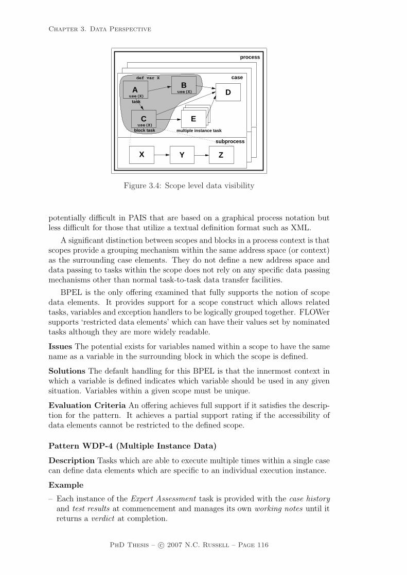
Chapter 3. Data Perspective
subprocess
case
multiple instance task
Dtask
block task
def var X
process
YX Z
use(X)
Ause(X)
B
C E
use(X)
Figure 3.4: Scope level data visibility
potentially difficult in PAIS that are based on a graphical process notation butless difficult for those that utilize a textual definition format such as XML.
A significant distinction between scopes and blocks in a process context is thatscopes provide a grouping mechanism within the same address space (or context)as the surrounding case elements. They do not define a new address space anddata passing to tasks within the scope does not rely on any specific data passingmechanisms other than normal task-to-task data transfer facilities.
BPEL is the only offering examined that fully supports the notion of scopedata elements. It provides support for a scope construct which allows relatedtasks, variables and exception handlers to be logically grouped together. FLOWersupports ‘restricted data elements’ which can have their values set by nominatedtasks although they are more widely readable.
Issues The potential exists for variables named within a scope to have the samename as a variable in the surrounding block in which the scope is defined.
Solutions The default handling for this BPEL is that the innermost context inwhich a variable is defined indicates which variable should be used in any givensituation. Variables within a given scope must be unique.
Evaluation Criteria An offering achieves full support if it satisfies the descrip-tion for the pattern. It achieves a partial support rating if the accessibility ofdata elements cannot be restricted to the defined scope.
Pattern WDP-4 (Multiple Instance Data)
Description Tasks which are able to execute multiple times within a single casecan define data elements which are specific to an individual execution instance.
Example
– Each instance of the Expert Assessment task is provided with the case historyand test results at commencement and manages its own working notes until itreturns a verdict at completion.
PhD Thesis – c© 2007 N.C. Russell – Page 116

Chapter 3. Data Perspective
Motivation Where a task executes multiple times, it is useful to be able to definea set of data elements which are specific to each individual execution instance.The values of these elements may be passed to the task instance at commencementand at the conclusion of its execution they can be made available (either on anindividual basis or as part of an aggregated data element) to subsequent tasks.There are three distinct scenarios in which a task could be executed more thanonce:
1. Where a particular task is designated as a multiple instance task and onceit is enabled, multiple instances of it are initiated simultaneously.
2. Where distinct tasks in a process share the same implementation.
3. Where a task can receive multiple initiation triggers (i.e. multiple tokens ina Petri-net sense) during the operation of a case.
Overview Each of these scenarios is illustrated in Figure 3.5 through processfragments based on the YAWL notation12. In the top lefthand diagram, taskE illustrates a multiple instance task. In the bottom lefthand diagram, taskD corresponds to both an XOR-join. When the XOR-join construct receives acontrol-flow triggering from any of the incoming arcs, it immediately invokes theassociated task. If it receives multiple triggers at distinct points in time, then thisresults in the task being invoked multiple times. In the righthand diagram, tasksC and E both share the same implementation that is defined by the subprocesscontaining tasks X and Y.
Shared Implementation
Subprocess
Designated Multiple Instance Task
Multiply Triggered Task
C
DBA
DA
C
DBA
B
C
X Y
E
E
E
Figure 3.5: Alternative implementations of multiple instance tasks
Context There are no specific context conditions associated with this pattern.
Implementation The ability to support distinct data elements in multiple taskinstances presumes the offering is also able to support data elements that can be
12Further details on YAWL are presented in van der Aalst and ter Hofstede [AH05].
PhD Thesis – c© 2007 N.C. Russell – Page 117

Chapter 3. Data Perspective
bound specifically to individual tasks (i.e. Task Data) in some form. Offeringslacking this capability are unable to facilitate the isolation of data elements be-tween task instances for any of the scenarios identified above. In addition to this,there are also other prerequisites for individual scenarios as described below.
In order to support multiple instance data in the first of the scenarios identifiedabove, the offering must also support designated multiple instance tasks and itmust provide facilities for composite data elements (e.g. arrays) to be split upand allocated to individual task instances for use during their execution and forthese data elements to be subsequently recombined for use by later tasks.
The second scenario requires the offering to provide task-level data bindingand support the capability for a given task to be able to receive multiple triggers.Each of the instances should have a mutually distinct set of data elements whichcan receive data passed from preceding tasks and pass them to subsequent tasks.
For the third scenario, it must be possible for two or more distinct blocktasks to share the same implementation (i.e. the same underlying subprocess)and the offering must support block-level data. Additionally these data elementsmust be able to be allocated values at commencement of the subprocess and fortheir values to be passed back to the calling (block) task once the subprocess hascompleted execution.
Of the various multiple instance scenarios identified, FLOWer provides sup-port for the first of them13. WebSphere MQ, COSA, XPDL and BPMN cansupport the second and WebSphere MQ, COSA, iPlanet and BPMN directlysupport the third scenario. UML 2.0 ADs support all three scenarios. Staffwarecan potentially support the third scenario also, however programmatic extensionswould be necessary to map individual instances to distinct case level variables.
Issues A significant issue that arises for PAIS that support designated multipleinstance tasks such as FLOWer involves the partitioning of composite data el-ements (such as an array) in a way that ensures each task instance receives adistinct portion of the data element that is passed to each of the multiple taskinstances.
Solutions FLOWer has a unique means of addressing this problem through map-ping objects which allow sections of a composite data element in the form of anarray (e.g. X[1], X[2] and so on) to be allocated to individual instances of a mul-tiple instance task (known as a dynamic plan). Each multiple task instance onlysees the element it has been allocated and each task instance has the same nam-ing for each of these elements (i.e. X). At the conclusion of all of the multipleinstances, the data elements are coalesced back into the composite form togetherwith any changes that have been made.
Evaluation Criteria An offering achieves full support if it has a construct thatsatisfies the description for the pattern. It achieves a partial support rating ifprogrammatic extensions are required to manage the partitioning and coalescenceof individual instances of the multiple instance data element.
13Recent documentation [GP03] suggests that Staffware will also support this constructshortly through addition of the Multiple Process Selection construct, although it has not beenobserved in the release examined during this evaluation.
PhD Thesis – c© 2007 N.C. Russell – Page 118

Chapter 3. Data Perspective
Pattern WDP-5 (Case Data)
Description Data elements are supported which are specific to a process instanceor case. They can be accessed by all components of the process during theexecution of the case.
Example
– The employee assessment results can be accessed by all of the tasks during thisexecution instance of the Performance Assessment workflow.
Motivation Data elements defined at case level effectively provide global datastorage during the execution of a specific case. Through their use, data can bemade accessible to all process components without the need to explicitly denotethe means by which it is passed between them.
Overview Figure 3.6 illustrates the use of the case level data element X which isutilized by all of the tasks throughout a process (including those in subprocesses).
subprocess
use(X)use(X)
task
block task multiple instance task
use(X) use(X) use(X)
process
case
BA
C
D
def var X
use(X) use(X)
use(X)
X ZY
E
Figure 3.6: Case level data visibility
Context There are no specific context conditions associated with this pattern.
Implementation Most offerings support the notion of case data in some form,however the approaches to its implementation vary widely. Staffware implementsa data management strategy that is based on the notion of a common data storefor each workflow case although individual data fields must be explicitly passedto subprocesses in order to make them accessible to the tasks within them. Web-Sphere MQ takes a different approach with a global data store being definedfor each workflow case for case level data elements but distinct data passingconventions needing to be specified to make this data accessible to individualtasks. COSA provides a series of types of data constructs with the INSTANCEtool agent corresponding to case level data elements which are globally accessiblethroughout a workflow case (and associated subprocesses) by default. BPMNsupports case data through the Properties attribute of a process. In FLOWer,XPDL and BPEL14, the default binding for data elements is at case level and
14Note that process level variables in BPEL (which are widely referred in the BPEL specifica-
PhD Thesis – c© 2007 N.C. Russell – Page 119

Chapter 3. Data Perspective
they are visible to all of the components in a process. UML 2.0 ADs do notsupport case data (or folder data) as all instances of a process appear to executein the same context.
Issues One consideration that arises with the use of case level data is in ensuringthat these elements are accessible, where required, to the components of a sub-process associated with a specific case (e.g. as part of the definition of a blocktask).
A second issue associated with the use of case level data is that of managingconcurrent access to it by multiple process instances.
Solutions The first issue is addressed in one of two ways. In some PAIS, subpro-cesses that are linked to a process model do not seem to be considered to be partof the same execution context as the main process. To remedy this issue, toolssuch as Staffware and WebSphere MQ require that case level data elements beexplicitly passed to and from subprocesses as parameters in order to make themvisible to the various components at this level. Alternatively PAIS can makethese data elements visible to all subprocesses by default, as is the situation inCOSA, FLOWer and XPDL.
There are not clear cut solutions to the second issue. Concurrency manage-ment is not an area that is currently well-addressed by commercial PAIS offerings.Where an offering provides for case level data, the general solutions to the concur-rency problem tend to be either to allow for the use of a third party transactionmanager (e.g. Staffware which allows Tuxedo to be used for transaction manage-ment) or to leave the problem to the auspices of the developer (e.g. COSA).
There has been significant research interest in the various forms of advancedtransaction support that are required for business processes [GV06, RS95b, WS97,AAA+96, DHL01] and several prototypes have been constructed which providevarying degrees of concurrency management and transactional support for work-flow systems, e.g. METEOR [KS95], EXOTICA [AAA+96], WIDE [GVA01],CrossFlow [VDGK00] and ConTracts [WR92], although most of these advanceshave yet to be incorporated in mainsteam commercial products.
Evaluation Criteria An offering achieves full support if it has a construct thatsatisfies the description for the pattern. It achieves a partial support rating ifcase data elements must be explicitly passed to and from subprocesses.
Pattern WDP-6 (Folder Data)
Description Data elements can be defined which are accessible by multiple caseson a selective basis. They are accessible to all components of the cases to whichthey are bound.
Example
– Selected instances of the Approve Travel Request task can access the currentcash reserves data element regardless of the case in which they execute, pro-viding they nominate the folder they require at case initiation.
tion as global variables) actually fulfill the requirements for the Case Data pattern as they arespecific to a given process instance. They do not provide support for the Global Data patterndiscussed subsequently which requires global access to a data element by all process instances.
PhD Thesis – c© 2007 N.C. Russell – Page 120

Chapter 3. Data Perspective
Motivation Folder data provides a mechanism for sharing a data element be-tween related task instances in different cases. This is particularly useful wheretasks in multiple cases are working on a related problem and require access tocommon working data elements.
Overview Figure 3.7 illustrates the notion of folder data. In essence, “folders”of related data elements are declared in the context of a process prior to theexecution of individual cases. Individual cases are able to nominate one or moreof these “folders” that their task instances should have access to during execution.Access may be read-only or read-write. In Figure 3.7, two folders are declared(A and B) containing data elements X and Y respectively. During the course ofexecution, case1 and case2 have access to folder A whereas case3 has access toboth folders A and B. As there is only one copy of each folder maintained, shouldany of case1, case2 or case3 execute concurrently, then they will in effect shareaccess to data element X. As a general rule, for folder data to be useful in anoffering, the cardinality of the accessibility relationship between folders and casesneeds to be m-n, i.e. data elements in a given folder need to be accessible to morethan one case and a given case needs to be able to access more than one datafolder during execution.
taskuse(X)A
use(X)B
case1
Cuse(X)
def var X
folderA folderB
def var Y
task
A B
case3
taskuse(X)A
use(X)B
case2
use(X,Y)use(X,Y)C
use(X,Y)
use (folder )
use (folder )
use (folder , folder )A
case datarepository
A
A
B
process
Cuse(X)
Figure 3.7: Folder data visibility
Context There are no specific context conditions associated with this pattern.
Implementation Of the offerings examined, only COSA offers the facility toshare data elements between cases on a selective basis. It achieves this by allowingeach case to be associated with a folder at commencement. At any time duringexecution of the case, it is possible for the current folder to be changed. The typeof access (read-only or read-write) and a range of access controls can be specifiedfor each folder at design time. It is also possible to use folders as repositories formore complex data elements such as documents.
PhD Thesis – c© 2007 N.C. Russell – Page 121

Chapter 3. Data Perspective
Issues As each folder defines its own context, one consideration that arises wherea case (or a task instance within a case) has access to multiple folders is hownaming clashes are resolved where two data elements in distinct folders share thesame name. A second issue that arises is that of providing concurrency controlfor folder level data .
Solutions The first issue is addressed in COSA by only allowing a case to accessattributes from one folder at a time. This is achieved using a specific Tool Agentfor folders. It is possible to change the folder to which a case refers at any time(again using a specific Tool Agent call). In terms of the second issue, similarconsiderations apply to those discussed for case data. In the case of COSA, thereis no direct system support to address this problem.
Evaluation Criteria An offering achieves full support if it has a construct thatsatisfies the description for the pattern.
Pattern WDP-7 (Global Data)
Description Data elements are supported which are accessible to all componentsin each and every case of the process and are defined within the context of theprocess itself.
Example
– The risk/premium matrix can be utilized by all of the cases of the Write In-surance Policy workflow and all tasks within each case.
Motivation Some data elements have sufficiently broad applicability that it isdesirable to make them accessible to every component in all cases of process ex-ecution. Data that falls into this category includes startup parameters to theoperating environment, global application data that is frequently used and pro-duction information that governs the potential course of execution that each casemay take.
Overview Figure 3.8 illustrates the extent of global data visibility. Note that incontrast to case level data elements which are typically only visible to tasks inthe case in which they are declared, global data elements are visible throughoutall cases.
Context There are no specific context conditions associated with this pattern.
Implementation In order to make data elements broadly accessible to all cases,most offerings address this requirement by utilising persistent storage, typicallyin the form of a database. This may be provided directly as an internal facility(e.g. tables, persistent lists, DEFINITION tool agents, packages and data ob-jects (ObjectNodes) in the case of Staffware, WebSphere MQ, COSA, XPDL andBPMN respectively) or by linking in/accessing facilities in a suitable third-partyproduct.
Issues The main issue associated with global data is in managing concurrentaccess to it by multiple processes.
Solutions As discussed for the Folder Data and Case Data patterns..
PhD Thesis – c© 2007 N.C. Russell – Page 122

Chapter 3. Data Perspective
subprocess
use(X)use(X)
use(X)
use(X)
task
multiple instance taskblock task
process
case
BA
C
D
use(X) use(X) use(X)
def var X
use(X)
ZYX
E
Figure 3.8: Global data visibility
Evaluation Criteria An offering achieves full support if it has a construct thatsatisfies the description for the pattern. It achieves a partial support rating if thevalue of these data elements cannot be modified during process execution.
Pattern WDP-8 (Environment Data)
Description Data elements which exist in the external operating environmentare able to be accessed by components of processes during execution.
Example
– Where required, tasks in the System Monitoring workflow can access the tem-perature sensor data from the operating environment.
Motivation Direct access to environmentally managed data by tasks or casesduring execution can significantly simplify processes and improve their ability torespond to changes and communicate with applications in the broader operationalenvironment.
Overview External data may be sourced from a variety of distinct locations in-cluding external databases, applications that are currently executing or can beinitiated in the operating environment and services that mediate access to vari-ous data repositories and distribution mechanisms, e.g. stock price feeds. Thesescenarios are illustrated in Figure 3.9.
Context There are no specific context conditions associated with this pattern.
Implementation The ability to access external data elements generally requiresthe ability to connect to an interface or interprocess communication (IPC) facilityin the operating environment or to invoke an external service which will supplydata elements. Facilities for achieving this may be either explicitly or implicitlysupported by an offering.
Explicit support involves the direct provision by an offering of constructs foraccessing external data sources. Typically these take the form of specific elementsthat can be included in the design-time process model. Staffware provides the
PhD Thesis – c© 2007 N.C. Russell – Page 123

Chapter 3. Data Perspective
subprocess
use(X,Y,Z) use(X,Y,Z) use(X,Y,Z)
use(X,Y,Z)task
multiple instance taskblock task
process
case
BA
C
D
external datarepository
def var X
def var Y
def var Z
serviceexternal
applicationexternal use(X,Y,Z)
use(X,Y,Z)
use(X,Y,Z)
use(X,Y,Z)
X ZY
E
Figure 3.9: Environment data visibility
Automatic Step construct as well as script commands which enable specific itemsof data to be requested from an external application. COSA provides the ToolAgent interfaces which provide a number of facilities for accessing external dataelements. FLOWer implements Mapping Objects which allow data elements tobe copied from external databases into the workflow engine, updated as requiredwith case data and copied back to the underlying database. It also allows textfiles to be utilized in workflow actions and has a series of interfaces for externaldatabase integration. BPEL provide facilities that enable external web servicesto be invoked thus facilitating access to environment data elements.
Implicit support occurs in offerings such as WebSphere MQ and iPlanet wherethe actual implementation of individual workflow tasks is achieved by the devel-opment of associated programs in a procedural language such as C++ or Java.In this situation, access to external data occurs within individual task implemen-tations by extending the program code to incorporate the required integrationcapabilities.
Issues There are a multitude of ways in which external data elements can beutilized within a process. It is infeasible for any offering to support more than ahandful of them. This raises the issue of the minimal set of external integrationfacilities required for effective external data integration.
Solutions There is no definitive answer to this problem as the set of facilitiesrequired depends on the context in which the tool will be utilized. Suitableoptions for accessing external data may include the ability to access data files(in text or binary format) in the operating environment or the ability to utilizean external API (e.g. an XML, DDE or ODBC interface) through which datarequests can be dynamically framed.
Evaluation Criteria An offering achieves full support if it satisfies the descrip-tion for the pattern. It achieves a partial support rating if external data elementscan only be accessed via programmatic extensions to the PAIS or if there arelimitations on the type of data elements that can be accessed.
PhD Thesis – c© 2007 N.C. Russell – Page 124
Chapter 3. Data Perspective
3.3 Data interaction patterns
This section examines the various ways in which data elements can be passedbetween components in a process and how the characteristics of the individualcomponents can influence the manner in which the trafficking of data elements oc-curs. Of particular interest is the distinction between the communication of databetween components within a process as against the data-oriented interaction ofa process element with the external environment.
3.3.1 Internal data interaction patterns
Pattern WDP-9 (Data Interaction – Task to Task)
Description The ability to communicate data elements between one task in-stance and another within the same case. The communication of data elementsbetween two tasks is specified in a form that is independent of the task definitionsthemselves.
Example
– The Determine Fuel Consumption task requires the coordinates determined bythe Identify Shortest Route task before it can proceed.
Motivation The passing of data elements between tasks is a fundamental aspectof PAIS. In many situations, individual tasks execute in their own distinct ad-dress space and do not share significant amounts of data on a global basis. Thisnecessitates the ability to move commonly used data elements between distincttasks as required.
Overview All PAIS support the notion of passing parameters from one taskto another however, this may occur in a number of distinct ways depending onthe relationship between the data perspective and control-flow perspective withinthe offering. There are three main approaches as illustrated in Figure 3.10. Thedistinctions between each of these are as follows:
• Integrated control and data channels – where both control-flow and dataare passed simultaneously between tasks utilising the same channel. In theexample, task B receives the data elements X and Y at exactly the sametime that control is passed to it. Whilst conceptually simple, one of thedisadvantages of this approach to data passing is that it requires all dataelements that may be used some time later in the process to be passed withthe thread of control regardless of whether the next task will use them ornot. For example, task B does not use data element Y but it is passed toit because task C will subsequently require access to it.
• Distinct data channels – in which data is passed between tasks via explicitdata channels which are distinct from the process control links within theprocess design. Under this approach, the coordination of data and controlpassing is usually not specifically identified. It is generally assumed thatwhen control is passed to a task that has incoming data channels, the data
PhD Thesis – c© 2007 N.C. Russell – Page 125

Chapter 3. Data Perspective
Global Data Store
C
CA B
C
Distinct Control and Data Channels
Integrated Control and Data Channels
A B
pass(X)
pass(Y)
pass(Y)pass(X,Y)A B
def var Xdef var Y
Global Shared Data
use(X,Y) use(X) use(Y)
use(X,Y) use(X) use(Y)
use(X,Y) use(X) use(Y)
task
task
task
Figure 3.10: Approaches to data interaction between tasks
elements specified on these channels will be available at the time of taskcommencement.
• Global data store – where tasks share the same data elements (typically viaaccess to globally shared data) and no explicit data passing is required (cf.the Case Data and Folder Data patterns). This approach to data sharing isbased on tasks having shared a priori knowledge of the naming and locationof common data elements. It also assumes that the implementation is ableto deal with potential concurrency issues that may arise where several taskinstances seek to access the same data element.
Context There are no specific context conditions associated with this pattern.
Implementation The majority of offerings examined adopt the third strategydescribed above. Staffware, FLOWer, COSA, iPlanet, XPDL and UML 2.0 ADsall facilitate the passing of data through case-level data repositories accessible byall tasks. BPEL utilizes a combination of the first and third approaches. Vari-ables can be bound to scopes within a process definition which may encompass anumber of tasks, but there is also the ability for messages to be passed betweentasks when control passes from one task to another. WebSphere MQ adopts thesecond mechanism with data elements being passed between tasks in the formof data containers via distinct data channels. BPMN supports all three imple-mentation alternatives allowing data to be passed using specific Data Objects(which may or may not be linked to a Sequence Flow depending on whether anintegrated control and data channel is required) or via the Properties attributeof a task.
PhD Thesis – c© 2007 N.C. Russell – Page 126

Chapter 3. Data Perspective
Issues There are several potential issues associated with the use of this pattern.First, where there is no data passing between tasks and a common data store isutilized by several tasks for communicating data elements, there is the potentialfor concurrency problems to arise, particularly if the case involves parallel execu-tion paths. This may lead to inconsistent results depending on the task executionsequence that is taken.
A second consideration arises where data and control-flow are passed along thesame channel. In this situation there is the potential for two (potentially differing)copies of the same data element to flow to the same task15, necessitating that thetask decide which is the correct version of the data element to use in its processingactivities.
A third consideration where data and control-flow occur via distinct channels,is that of managing the situation where the control-flow reaches a task before therequired data elements have been passed to it.
Solutions The first issues – concurrency control – is handled in a variety of dif-ferent ways by the offerings examined in Section 3.6. FLOWer avoids the problemby only allowing one active user or process that can update data elements in acase at any time (although other processes and users can access data elementsfor reading). BPEL supports serializable scopes which allow compensation han-dlers to be defined for groups of tasks that access the same data elements. Acompensation handler is a procedure that aims to undo or compensate for theeffects of the failure of a task on other tasks that may rely on it or on data thatit has affected. Staffware provides the option to utilize an external transactionmanager (Tuxedo) within the context of the workflow cases that it facilitates.
In terms of the second issue, no general solutions to this problem have beenidentified. Of the offerings observed, only BPEL supports the simultaneous pass-ing of control-flow and data along the same channel and it does not provide asolution to the issue.
The third issue is addressed in WebSphere MQ (which has distinct data andcontrol-flow channels) by ensuring that the task instance waits for the requireddata elements to arrive before commencing execution.
Evaluation Criteria An offering achieves full support if it has a construct thatsatisfies the description for the pattern.
Pattern WDP-10 (Data Interaction – Block Task to Subprocess De-composition)
Description The ability to pass data elements from a block task to the corre-sponding subprocess that defines its implementation. Any data elements that areavailable to a block task are able to be passed to (or be accessed) in the associatedsubprocess although only a specifically nominated subset of those data elementsare actually passed to the subprocess.
15For example, access to a given data element may be required in three branches within aprocess, requiring the original data element to be replicated and passed to one or more tasksin each branch. The difficulty arises where the data element is altered in one branch and thebranches subsequently converge at a join operator.
PhD Thesis – c© 2007 N.C. Russell – Page 127

Chapter 3. Data Perspective
Example
– Customer claims data is passed to the Calculate Likely Tax Return block taskwhose implementation is defined by a series of tasks in the form of a subprocess.The customer claims data is passed to the subprocess and is visible to each ofthe tasks in the subprocess.
Motivation In order for subprocesses to be used in an effective manner withina process model, a mechanism is required that allows data elements to be passedto them.
Overview Most PAIS support the notion of composite or block tasks in someform. These are analogous to the programmatic notion of procedure calls andindicate a task whose implementation is described in further detail at another levelof abstraction (typically elsewhere in the process design) using the same rangeof process constructs. The question that arises when data is passed to a blockelement is whether it is immediately accessible by all of the tasks that define itsactual implementation or if some form of explicit data passing must occur betweenthe block task and the subprocess. Typically one of three approaches is taken tohandling the communication of parameters from a block task to the underlyingimplementation. Each of these is illustrated in Figure 3.11. The characteristicsof each approach are as follows:
• Implicit data passing – data passed to the block task is immediately ac-cessible to all sub-tasks which make up the underlying implementation. Ineffect the main block task and the corresponding subprocess share the sameaddress space and no explicit data passing is necessary.
• Explicit data passing via parameters – data elements supplied to the blocktask must be specifically passed as parameters to the underlying subprocessimplementation. The second example in Figure 3.11 illustrates how thespecification of parameters can handle the mapping of data elements atblock task level to data elements at subprocess level with distinct names.This capability provides a degree of independence in the naming of dataelements between the block task and subprocess implementation and isparticularly important in the situation where several block tasks share thesame subprocess implementation.
• Explicit data passing via data channels – data elements supplied to the blocktask are specifically passed via data channels to all tasks in the subprocessthat require access to them.
Context There are no specific context conditions associated with this pattern.
Implementation All of the approaches described above have been observed inthe offerings examined. The first approach does not involve any actual datapassing between block activity and implementation, rather the block level dataelements are made accessible to the subprocess. This strategy is utilized byFLOWer, COSA and BPMN for data passing to subprocesses. In all cases, thesubprocess is presented with the entire range of data elements utilied by the blocktask and there is no opportunity to limit the scope of items passed.
PhD Thesis – c© 2007 N.C. Russell – Page 128

Chapter 3. Data Perspective
subprocess
pass(M,N)
pass(N)pass(M,N)
pass(M,N) pass(M,N)
pass(N)
pass(M)
block task
task
block task
task
task
block task
subprocess
subprocess
X ZY
A
X ZY
A
A
Explicit Data Passing via Parameters
Implicit Data Passing
Explicit Data Passing via Data Channels
pass(M,N) pass(M,N)
X ZYuse(P,Q)
use(M,N)pass(M,N) pass(M,N)
use(P,Q)
use(M,N) use(M) use(N)
use(M,N)
use(P,Q)
use(M,N) use(M)
use(M,N)
use(N)
pass(M,N)
parameter output
return N := Q
parameter input
def var P := M return M := P
subprocesssubprocess
def var Q := N
Figure 3.11: Approaches to data interaction from block tasks to correspondingsubprocesses
The third approach relies on the passing of data elements between tasks tocommunicate between block task and subprocess. Both Staffware and XPDLutilize this mechanism for passing data elements to subprocesses.
In contrast, the second approach necessitates the creation of new data el-ements at subprocess level to accept the incoming data values from the blockactivity. WebSphere MQ follows this strategy and sink and source nodes areused to pass data containers between the parent task and corresponding sub-process. iPlanet does so using parameters based on commonly named processattributes in the parent task and subprocess. BPMN and UML 2.0 ADs canalso utilize this approach through InputPropertyMaps expressions (and Output-PropertyMaps where the data passing is from subprocess to parent task) andParameters respectively.
Issues One consideration that may arise where the explicit parameter passingapproach is adopted is whether the data elements in the block task and thesubprocess are independent of each other (i.e. whether they exist in independentaddress spaces). If they do not, then the potential exists for concurrency issuesto arise as tasks executing in parallel update the same data element.
PhD Thesis – c© 2007 N.C. Russell – Page 129

Chapter 3. Data Perspective
Solutions This issue can arise with Staffware where subprocess data elementsare passed as fields rather than parameters. The resolution to this issue is to mapthe input fields to fields with distinct names not used elsewhere during executionof the case.
Evaluation Criteria An offering achieves full support if it has a construct thatsatisfies the description for the pattern. It achieves a partial support rating ifit is not possible to limit the range of data elements which are accessible to thesubprocess.
Pattern WDP-11 (Data Interaction – Subprocess Decomposition toBlock Task)
Description The ability to pass data elements from the underlying subprocessback to the corresponding block task. Only nominated data elements defined aspart of the subprocess are made available to the (parent) block task.
Example
– The Determine Optimal Trajectory subprocess passes the coordinates of thelaunch and target locations and the flight plan back to the block task.
Motivation At the conclusion of the underlying subprocess, the data elementswhich have resulted from its execution need to be made available to the blocktask which called it.
Overview The approaches taken to handling this pattern are essentially thesame as those identified for the Data Interaction – Block Task to SubprocessDecomposition pattern (WDP-10). Where data elements are passed on an explicitbasis, a mapping needs to be specified for each output parameter indicating whichdata element at block level will receive the relevant output value.
Context There are no specific context conditions associated with this pattern.
Implementation As for the Data Interaction – Block Task to Subprocess De-composition pattern.
Issues One difficulty that can arise with the implementation of this pattern occurswhen there is not a strict correspondence between the data elements returnedfrom the subprocess and the receiving data elements at block task level. E.g. thesubprocess returns more data elements than the block task is expecting, possiblyas a result of additional data elements being created during its execution.
Solutions This problem can be solved in one of two ways. Some offerings suchas Staffware support the ability for block tasks to create data elements at blocktask level for those data items at subprocess level which it has not previouslyencountered. Other products such as WebSphere MQ require a strict mappingto be defined between subprocess and block task data elements to prevent thissituation from arising.
Evaluation Criteria An offering achieves full support if it has a construct thatsatisfies the description for the pattern. It achieves a partial support rating ifit is not possible to limit the range of data elements which are passed from thesubprocess to the block task.
PhD Thesis – c© 2007 N.C. Russell – Page 130

Chapter 3. Data Perspective
Pattern WDP-12 (Data Interaction – to Multiple Instance Task)
Description The ability to pass data elements from a preceding task to a sub-sequent task which is able to support multiple execution instances. This mayinvolve passing the data elements to all instances of the multiple instance task ordistributing them on a selective basis. The data passing occurs when the multipleinstance task is enabled.
Examples
– The Identify Witnesses task passes the witness list to the Interview Witnessestask. This data is available to each instance of the Interview Witnesses taskat commencement.
– The New Albums List is passed to the Review Album task and one task instanceis started for each entry on the list. At commencement, each of the ReviewAlbum task instances is allocated a distinct entry from the New Album List toreview.
Motivation Where a task is capable of being invoked multiple times, a means isrequired of controlling which data elements are passed to each of the executioninstances. This may involve ensuring that each task instance receives all of thedata elements passed to it (possibly on a shared basis) or distributing the dataelements across each of the execution instances on some predefined basis.
Overview There are three potential approaches to passing data elements tomultiple instance tasks as illustrated in Figure 3.12. As a general rule, it ispossible either to pass a data element to all task instances or to distribute oneitem from it (assuming it is a composite data element such as an array or a set)to each task instance. Indeed the number of task instances that are initiated maybe based on the number of individual items in the composite data element. Thespecifics of each of these approaches are discussed below.
• Instance-specific data passed by value – this involves the distribution of adata element passed by value to task instances on the basis of one item ofthe data element per task instance (in the example shown, task instance B1
receives M[1], B2 receives M[2] and so on). As the data element is passedby value, each task instance receives a copy of the item passed to it in itsown address space. At the conclusion of each of the task instances, thedata element is reassembled from the distributed items and passed to thesubsequent task instance.
• Instance-specific data passed by reference – this scenario is similar to thatdescribed above except that the task instances are passed a reference to aspecific item in the data element rather than the value of the item. Thisapproach avoids the need to reassemble the data element at the conclusionof the task instances.
• Shared data passed by reference – in this situation all task instances arepassed a reference to the same data element. Whilst this allows all taskinstances to access the same data element, it does not address the issue ofconcurrency control should one of the task instances amend the value ofthe data element (or indeed if it is altered by some other component of theprocess).
PhD Thesis – c© 2007 N.C. Russell – Page 131

Chapter 3. Data Perspective
use(M[3])
3B
3B
B
use(M)
use(*M)
3use(*M)
use(*M)
use(*M[3])
use(M[2])B
B
use(*M[2])B
2
2
2
instances
use(*M[1])
multiple instance task
..
.....
.....
.....1
2
3
4
Shared Data Storage array M:
Instance−Specific Data
B
A
use(M[1])
use(M)
Cpass(M) pass(M)
instances
multiple instance task
multiple instance task
B
Ause(*M)
Cpass(&M)pass(&M)
task instance
Passed by Reference
Passed By ReferenceShared Data
Shared Data Storage var M: .....
Passed by ValueInstance−Specific Data
B
Ause(*M)
Cpass(&M)pass(&M)
task instance
task instance
use(*M)
use(*M)
instances
task instance
task instancetask instance
1
1
1
Figure 3.12: Data interaction approaches for multiple instance tasks
Context There are no specific context conditions associated with this pattern.
Implementation FLOWer provides facilities for instance-specific data to bepassed by reference whereby an array can be passed to a designated multipleinstance task and specific sub-components of it can be mapped to individual taskinstances. It also allows for shared data elements to be passed by reference toall task instances. UML 2.0 ADs allow data to be partitioned (and aggregated)across multiple task instances using the ExpansionRegion construct.
Issues Where a task is able to execute multiple times but not all instances arecreated at the same time, an issue that arises is whether the values of dataelements are set for all execution instances at the time at which the multipleinstance task is first initiated or whether they can be set after this occurs for theinvocation of a specific task instance.
PhD Thesis – c© 2007 N.C. Russell – Page 132

Chapter 3. Data Perspective
Solutions In FLOWer, the Dynamic Plan construct allows the data for individualtask instances to be specified at any time prior to the actual invocation of the taskinstance. The passing of data elements to specific task instances is handled viaMapping Array data structures. These can be extended at any time during theexecution of a Dynamic Plan, allowing for new task instances to be created ‘onthe fly’ and the data corresponding to them to be specified at the latest possibletime. This issue does not arise in offerings such as UML 2.0 ADs as all instancesmust be created at the commencement of the task.
Evaluation Criteria An offering achieves full support if it has a construct thatsatisfies the description for the pattern.
Pattern WDP-13 (Data Interaction – from Multiple Instance Task)
Description The ability to pass data elements from a task which supports mul-tiple execution instances to a subsequent task. The data passing occurs at theconclusion of the multiple instance task. It involves aggregating data elementsfrom all instances of the task and passing them to a subsequent task.
Example
– At the conclusion of the various instances of the Record Lap Time task, thelist of lap times is passed to the Prepare Grid task.
Motivation Each execution instance of a multiple instance task effectively op-erates independently from other instances and as such, has a requirement to passon data elements at its conclusion to subsequent tasks.
Overview In general, data is passed from a multiple instance task to subsequenttasks when a certain number of the task instances have concluded. The variousscenarios in which this may occur are illustrated in Figure 3.12. These usuallycoincide with the passing of control from the multiple instance task although dataand control-flow do not necessarily need to be fully integrated. In the case wheredata elements are passed by reference, the location rather than the values arepassed on at task completion (obviously this implies that the data values may beaccessed by other components of the process prior to completion of the multipleinstance task as they reside in shared storage).
Context There are no specific context conditions associated with this pattern.
Implementation FLOWer provides facilities for instance-specific data to be ag-gregated from a series of task instances and passed to a subsequent task. UML2.0 ADs support this pattern via the ExpansionRegion construct.
Issues One issue that arises with multiple instance tasks is identifying the pointat which the output data elements from them are available (in some aggregateform) to subsequent tasks.
Solutions In the case of FLOWer, this issue is dependent on where the dataelements are accessed from. The FLOWer engine allows parallel task instancesto access output data elements from other instances even if these instances havenot yet completed (i.e. the values obtained, if any, may not be final). Howeversubsequent task instances (i.e. those after the multiple instance task), can rely onthe complete composite data element being available. UML 2.0 ADs only allow
PhD Thesis – c© 2007 N.C. Russell – Page 133
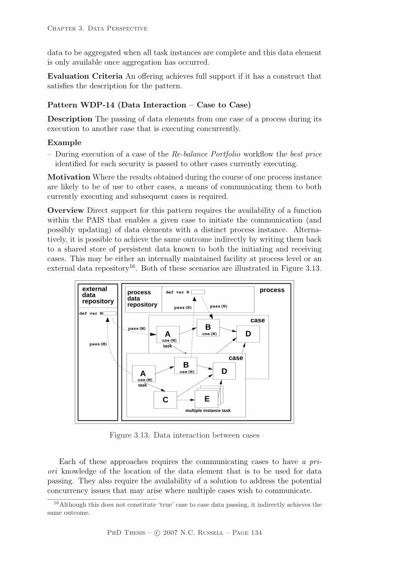
Chapter 3. Data Perspective
data to be aggregated when all task instances are complete and this data elementis only available once aggregation has occurred.
Evaluation Criteria An offering achieves full support if it has a construct thatsatisfies the description for the pattern.
Pattern WDP-14 (Data Interaction – Case to Case)
Description The passing of data elements from one case of a process during itsexecution to another case that is executing concurrently.
Example
– During execution of a case of the Re-balance Portfolio workflow the best priceidentified for each security is passed to other cases currently executing.
Motivation Where the results obtained during the course of one process instanceare likely to be of use to other cases, a means of communicating them to bothcurrently executing and subsequent cases is required.
Overview Direct support for this pattern requires the availability of a functionwithin the PAIS that enables a given case to initiate the communication (andpossibly updating) of data elements with a distinct process instance. Alterna-tively, it is possible to achieve the same outcome indirectly by writing them backto a shared store of persistent data known to both the initiating and receivingcases. This may be either an internally maintained facility at process level or anexternal data repository16. Both of these scenarios are illustrated in Figure 3.13.
C Etask
dataprocess
repositorydef var M
def var N
pass(M)
pass(N)
Ause(M)
case
DB
use(N)pass(M)
externaldatarepository
pass(N)
task
multiple instance task
task
use(N)B
D
case
process
A
C
use(M)
E
Figure 3.13: Data interaction between cases
Each of these approaches requires the communicating cases to have a pri-ori knowledge of the location of the data element that is to be used for datapassing. They also require the availability of a solution to address the potentialconcurrency issues that may arise where multiple cases wish to communicate.
16Although this does not constitute ‘true’ case to case data passing, it indirectly achieves thesame outcome.
PhD Thesis – c© 2007 N.C. Russell – Page 134

Chapter 3. Data Perspective
Context There are no specific context conditions associated with this pattern.
Implementation COSA is the only offering examined that supports a directmethod for communicating data elements between cases. It achieves this usingshared “folder” data elements (cf. the Folder Data pattern (WDP-6)). In thecase of the other offerings, it is possible to achieve the same result indirectly foreach of them using the methods described above.
Issues The main consideration associated with this pattern is in establishing aneffective means of linking related cases and their associated data together in ameaningful way.
Solutions None of the offerings examined address this need, however there arePAIS that provide solutions to the issue. In Vectus17 it is possible to relatecases. There are four types of relationships “parent”, “child”, “sibling”, and“master”. These relationships can be used to navigate through cases at runtime.For example, one case can schedule tasks in another flow, terminate a task inanother flow, create new cases, etc. It is also possible to share data using a dotnotation similar to that used in the Object Constraint Language [OMG05]. The“master” relation can be used to create a proxy shared by related cases to showall tasks related to these cases. A similar construct is also present in the BizAgi18
product.
Evaluation Criteria An offering achieves full support if it has a construct thatsatisfies the description for the pattern. It rates as partial support if it is necessaryto store the data element in an intermediate location to pass it between cases.
3.3.2 External data interaction patterns
External data interaction involves the communication of data between a compo-nent of a process and some form of information resource or service that operatesoutside of the context of the process environment. The notion of being external tothe context of the process environment applies not only in technology terms butalso implies that the operation of the external service or resource is independentof that of the process. The various types of interactions between elements of aprocess and the broader operational environment are considered in this section.
Pattern WDP-15 (Data Interaction – Task to Environment – Push-Oriented)
Description The ability of a task to initiate the passing of data elements to aresource or service in the operating environment.
Example
– The Calculate Mileage task passes the mileage data to the Corporate Logbookdatabase for permanent recording.
Motivation The passing of data from a task to an external resource is most likelyto be initiated by the task itself during its execution. Depending on the specific
17http://www.london-bridge.com18http://www.visionsoftware.biz
PhD Thesis – c© 2007 N.C. Russell – Page 135

Chapter 3. Data Perspective
requirements of the data passing interaction, it may connect to an existing APIor service interface in the operating environment or it may actually invoke theapplication or service to which it is forwarding the data.
Overview Figure 3.14 illustrates the various data passing scenarios between tasksand the operating environment. There are a wide range of ways in which thispattern can be achieved, however these tend to divide into two categories:
• Explicit integration mechanisms – where the process environment providesspecific constructs for passing data to the external environment.
• Implicit integration mechanisms – where the data passing occurs implicitlywithin the programmatic implementations that make up tasks in the processand is not directly supported by the process environment.
In both cases, the data passing activity is initiated by the task and occurssynchronously with task execution. Although, it is typically task-level data el-ements that are trafficked, any data items that are accessible to the task (i.e.parameters, scope, block, case, folder and global data) may be transferred.
task
pattern 18
pattern 17
pattern 16
pattern 15 case
processexternal
D
C
request(N)
pass(N)
task
process
BA
E
request(T)
def var Sdef var T
pass(M)def var M
def var N
pass(T)
pass(S)
Figure 3.14: Data interaction between tasks and the operating environment
Context There are no specific context conditions associated with this pattern.
Implementation Staffware provides the Automatic Step construct for passingdata elements from task instances to external programs. FLOWer enables datato be passed to external applications using the Operation Action construct andto external databases using Mapping Objects. COSA provides a broad numberof Tool Agents which facilitate the passing of data to external applications anddatabases. Similarly iPlanet provides a range of XML and HTTP-based mech-anisms that can be incorporated in task implementations for passing data toexternal applications. WebSphere MQ is more limited in its support and del-egates the passing of data elements to user-defined program implementations.BPMN supports the pattern via a Message Flow from a Task to the boundaryof a Pool representing the environment. XPDL and BPEL are limited to passingdata elements to web services.
PhD Thesis – c© 2007 N.C. Russell – Page 136

Chapter 3. Data Perspective
Issues One difficulty that can arise when sending data to an external applicationis knowing whether it was successfully delivered. This is particularly a problemwhen the external application does not provide immediate feedback on deliverystatus.
Solutions The most general solution to this problem is for a subsequent task inthe case to request an update on the status of the delivery using a construct whichconforms to the Data Interaction – Environment to Task – Pull-Oriented pattern(WDP-16) and requires an answer to be provided by the external application.Alternatively, the external application can lodge a notification of the deliveryusing some form of Event-based Task Trigger (i.e. pattern WDP-38) or by passingdata back to the process (e.g. using the Data Interaction – Environment to Task– Push-Oriented pattern (WDP-17)). This is analogous to the messaging notionof asynchronous callback.
Evaluation Criteria An offering achieves full support if it has a construct thatsatisfies the description for the pattern. It achieves a partial support rating ifprogrammatic extensions are required to facilitate the data passing.
Pattern WDP-16 (Data Interaction – Environment to Task – Pull-Oriented)
Description The ability of a task to request data elements from resources orservices in the operational environment.
Example
– The Determine Cost task must request cattle price data from the Cattle MarketSystem before it can proceed.
Motivation Tasks require the means to proactively seek the latest informationfrom known data sources in the operating environment during their execution.This may involve accessing the data from a known repository or invoking anexternal service in order to gain access to the required data elements.
Overview Similar to the Data Interaction — Task to Environment — Push-Oriented pattern (WDP-15), distinct PAIS support this pattern in a variety ofways however these approaches divide into two categories:
• Explicit integration mechanisms – where the PAIS provides specific con-structs for accessing data in the external environment.
• Implicit integration mechanisms – where access to external data occursat the level of the programmatic implementations that make up tasks inthe offering and is not directly supported by the PAIS. Interaction withexternal data sources typically utilizes interprocess communication (IPC)facilities provided by the operating system facilities such as message queuesor remote procedure calls, or enterprise application integration (EAI) mech-anisms such as DCOM19, CORBA20 or JMS21.
19Distributed Component Object Model. See http://www.microsoft.com for details.20Common Object Request Broker Architecture. See http://www.omg.org for details.21Java Messaging Service. See http://java.sun.com for details.
PhD Thesis – c© 2007 N.C. Russell – Page 137

Chapter 3. Data Perspective
Context There are no specific context conditions associated with this pattern.
Implementation Staffware provides two distinct constructs that support thisobjective. Automatic Steps allow external systems to be called (e.g. databasesor enterprise applications) and specific data items to be requested. Scripts allowexternal programs to be called either directly at system level or via system inter-faces such as DDE22 to access required data elements. FLOWer utilizes MappingObjects to extract data elements from external databases. COSA has a numberof Tool Agent facilities for requesting data from external applications. Similarly,iPlanet provides a range of XML and HTTP-based integration functions that canbe included in task implementations for requesting external data. BPMN sup-ports the pattern via a pair of Message Flows, one from a Task to the boundaryof a Pool representing the environment and the other in the reverse direction thusdepicting a synchronous data request. XPDL and BPEL provide facilities for thesynchronous request of data from other web services. In contrast, WebSphere MQdoes not provide any facilities for external integration and requires the underlyingprograms that implement workflow tasks to provide these capabilities where theyare required.
Issues One difficulty with this style of interaction is that it can block progressof the requesting case if the external application has a long delivery time for therequired information or is temporarily unavailable.
Solutions The only potential solution to this problem is for the requesting casenot to wait for the requested data (or continue execution after a nominated time-out) and to implement some form of asynchronous notification of the requiredinformation (possibly along the lines of pattern WDP-17). The disadvantage ofthis approach is that it complicates the overall interaction by requiring the ex-ternal application to return the required information via an alternate path andnecessitating the process environment to provide notification facilities.
Evaluation Criteria An offering achieves full support if it has a construct thatsatisfies the description for the pattern. It achieves a partial support rating ifprogrammatic extensions are required to facilitate the data passing.
Pattern WDP-17 (Data Interaction – Environment to Task – Push-Oriented)
Description The ability for a task to receive and utilize data elements passed toit from services and resources in the operating environment on an unscheduledbasis.
Example
– During execution, the Review Performance task may receive new engine teleme-try data from the Wireless Car Sensors.
Motivation An ongoing difficulty for tasks is establishing mechanisms that en-able them to be provided with new items of data as they become available fromsources outside of the process environment. This is particularly important inareas of volatile information where updates to existing data elements may occur
22Dynamic Data Exchange. See http://www.microsoft.com for details.
PhD Thesis – c© 2007 N.C. Russell – Page 138
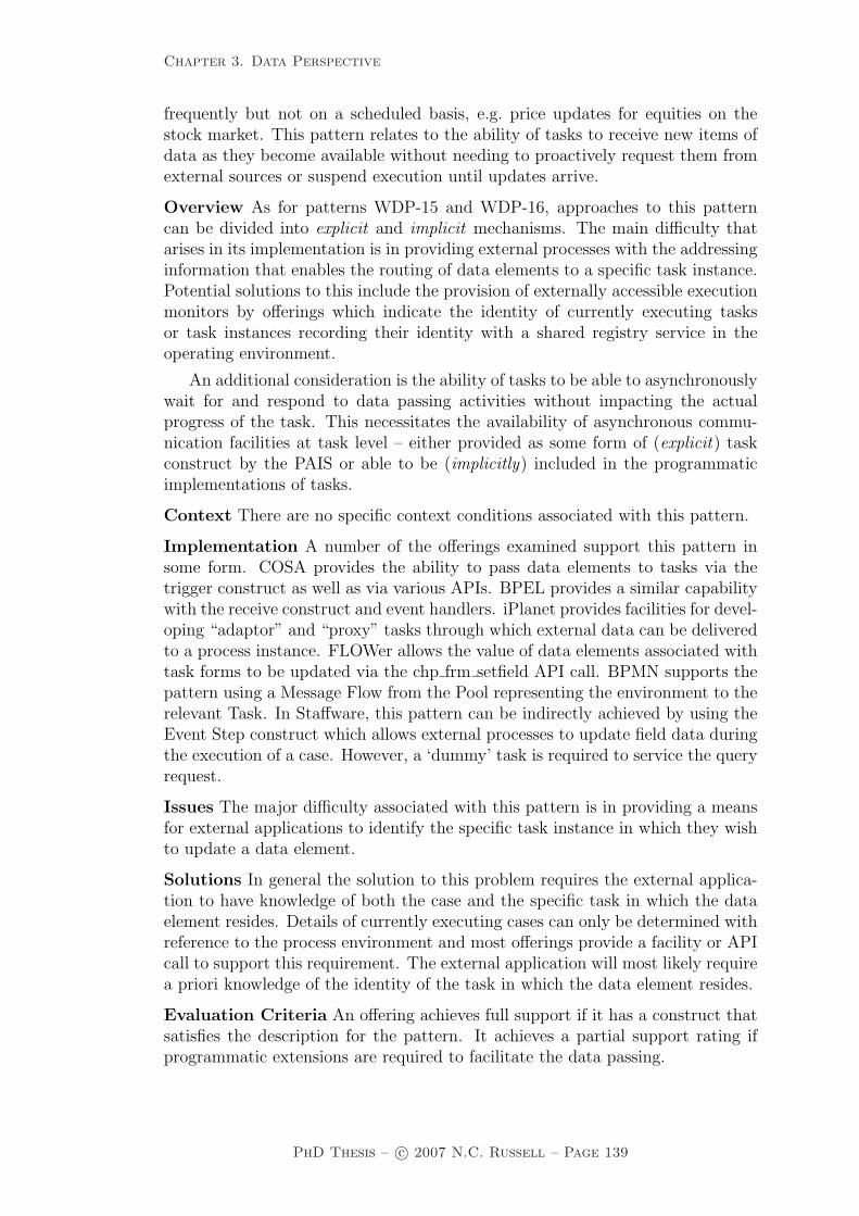
Chapter 3. Data Perspective
frequently but not on a scheduled basis, e.g. price updates for equities on thestock market. This pattern relates to the ability of tasks to receive new items ofdata as they become available without needing to proactively request them fromexternal sources or suspend execution until updates arrive.
Overview As for patterns WDP-15 and WDP-16, approaches to this patterncan be divided into explicit and implicit mechanisms. The main difficulty thatarises in its implementation is in providing external processes with the addressinginformation that enables the routing of data elements to a specific task instance.Potential solutions to this include the provision of externally accessible executionmonitors by offerings which indicate the identity of currently executing tasksor task instances recording their identity with a shared registry service in theoperating environment.
An additional consideration is the ability of tasks to be able to asynchronouslywait for and respond to data passing activities without impacting the actualprogress of the task. This necessitates the availability of asynchronous commu-nication facilities at task level – either provided as some form of (explicit) taskconstruct by the PAIS or able to be (implicitly) included in the programmaticimplementations of tasks.
Context There are no specific context conditions associated with this pattern.
Implementation A number of the offerings examined support this pattern insome form. COSA provides the ability to pass data elements to tasks via thetrigger construct as well as via various APIs. BPEL provides a similar capabilitywith the receive construct and event handlers. iPlanet provides facilities for devel-oping “adaptor” and “proxy” tasks through which external data can be deliveredto a process instance. FLOWer allows the value of data elements associated withtask forms to be updated via the chp frm setfield API call. BPMN supports thepattern using a Message Flow from the Pool representing the environment to therelevant Task. In Staffware, this pattern can be indirectly achieved by using theEvent Step construct which allows external processes to update field data duringthe execution of a case. However, a ‘dummy’ task is required to service the queryrequest.
Issues The major difficulty associated with this pattern is in providing a meansfor external applications to identify the specific task instance in which they wishto update a data element.
Solutions In general the solution to this problem requires the external applica-tion to have knowledge of both the case and the specific task in which the dataelement resides. Details of currently executing cases can only be determined withreference to the process environment and most offerings provide a facility or APIcall to support this requirement. The external application will most likely requirea priori knowledge of the identity of the task in which the data element resides.
Evaluation Criteria An offering achieves full support if it has a construct thatsatisfies the description for the pattern. It achieves a partial support rating ifprogrammatic extensions are required to facilitate the data passing.
PhD Thesis – c© 2007 N.C. Russell – Page 139

Chapter 3. Data Perspective
Pattern WDP-18 (Data Interaction – Task to Environment – Pull-Oriented)
Description The ability of a task to receive and respond to requests for dataelements from services and resources in the operational environment.
Example
– During execution, the Assess Quality task may receive requests for currentdata from the Quality Audit web service handler. It must provide this servicewith details of all current data elements.
Motivation In some cases, the requests for access to task instance data areinitiated by external processes. These requests need to be handled as soon as theyare received but should be processed in a manner that minimizes any potentialimpact on the task instance from which they are sourcing data.
Overview The ability to access data from a task instance can be handled in oneof three ways:
1. The offering can provide a means of accessing task instance data from theexternal environment.
2. During their execution, tasks instances publish data values to a well-knownlocation e.g. a database that can be accessed externally.
3. Task instances incorporate facilities to service requests for their data fromexternal processes.
Context There are no specific context conditions associated with this pattern.
Implementation In practice, this facility is not widely supported as an explicitconstruct by the offerings examined. BPEL provides direct support for the pat-tern (via the receive construct and event handlers). Staffware provides the EISReport construct and EIS Case Data Extraction facilities to enable the values ofdata elements to be requested from cases. COSA provides APIs for getting thevalues of various types of workflow data elements from the external environment(both at command line level and also programmatically). iPlanet provides fa-cilities for developing “adaptor” and “proxy” tasks through which external datacan be requested from within a process instance. BPMN supports this type ofinteraction using Message Flows. FLOWer provides an indirect solution via thechp frm getfield API call although this method has limited generality.
Issues Similar difficulties exist with the utilization of this pattern to those iden-tified above for pattern WDP-17.
Solutions As detailed above for pattern WDP-17.
Evaluation Criteria An offering achieves full support if it has a construct thatsatisfies the description for the pattern. It achieves a partial support rating ifprogrammatic extensions are required to facilitate the data passing.
PhD Thesis – c© 2007 N.C. Russell – Page 140

Chapter 3. Data Perspective
Pattern WDP-19 (Data Interaction – Case to Environment – Push-Oriented)
Description The ability of a case to initiate the passing of data elements to aresource or service in the operational environment.
Example
– At its conclusion, each case of the Perform Reconciliation workflow passes itsresults to the Corporate Audit database for permanent storage.
Motivation An alternative (or possible extension) to task-level data passing isto provide facilities for passing data at the level of the case.
Overview The various options for this approach to data passing are illustrated inFigure 3.15. This pattern is analogous to pattern WDP-15 except that it operatesin the context of a process instance.
task
pattern 21
pattern 19
pattern 22
pattern 20
process
case data repositorydef var M def var N
processexternal
case
BD
A
C
task
E
def var T
pass(S)
pass(T)
request(T)
pass(N)
request(N)
pass(M)
def var S
Figure 3.15: Data interaction between cases and the operating environment
Context There are no specific context conditions associated with this pattern.
Implementation This pattern has not been widely observed in the PAIS eval-uated in Section 3.6. Its implementation requires explicit support by an offeringfor case-initiated data passing which is independent of the task instances thatcomprise the case. Maximal flexibility for this pattern is gained through the useof a rule-based approach to the triggering of the data passing action. Potentialinvocation criteria include state-based conditions (e.g. case initiation, case com-pletion), data-based conditions (e.g. pass the data element when a nominateddata condition is satisfied) and temporal conditions (e.g. emit the value of a dataelement periodically during case execution). FLOWer provides a mechanism forsynchronising case data elements with an external database through the use ofmapping constructs which are triggered for each activity in a plan. This pro-vides a mechanism for providing external visibility of data elements during theexecution of a case.
Issues The main issue associated with this pattern is determining an appropriatetime to undertake the “push” action of the data element from the case to theenvironment.
PhD Thesis – c© 2007 N.C. Russell – Page 141

Chapter 3. Data Perspective
Solutions There are many points during case execution at which the externalcommunication of a data element does not seem to be sensible. In the case ofFLOWer, this action occurs at the conclusion of a specific task (or tasks) withinthe case. It would also seem to be appropriate at the conclusion of a case.
Evaluation Criteria An offering achieves full support if it satisfies the contextcriterion for the pattern.
Pattern WDP-20 (Data Interaction – Environment to Case – Pull-Oriented)
Description The ability of a case to request data from services or resources inthe operational environment.
Example
– At any time cases of the Process Suspect process may request additional datafrom the Police Records System.
Motivation In the event that a case requires access to the most current values ofexternal data elements during execution, it may not be sufficient for these valuesto be specified at the initiation of the case. Instead, facilities may be requiredfor them to be accessed during the course of execution at the point in the casewhere they are most likely to be needed.
Overview As for pattern WDP-19.
Context There are no specific context conditions associated with this pattern.
Implementation Similar to pattern WDP-19, this pattern has not been widelyobserved in the PAIS evaluated in Section 3.6. Once again, its implementationrequires explicit support by an offering for the extraction of data elements fromexternal applications. FLOWer provides this capability via mapping functionslinked to each activity in a plan which extract required data elements from anexternal database.
Issues The main issue associated with this pattern is determining an appropriatetime to undertake the “pull” action of the data element from the environment tothe case.
Solutions As for the previous pattern, there are many points during case ex-ecution at which the update of a data element from a source in the operatingenvironment does not seem to be sensible. In the case of FLOWer, this actionoccurs at the beginning of a specific task (or tasks) within the case. It would alsoseem to be appropriate to pass required data elements from the environment atthe beginning of a case.
Evaluation Criteria An offering achieves full support if it has a construct thatsatisfies the description for the pattern.
Pattern WDP-21 (Data Interaction – Environment to Case – Push-Oriented)
Description The ability of a case to accept data elements passed to it fromservices or resources in the operating environment.
PhD Thesis – c© 2007 N.C. Russell – Page 142

Chapter 3. Data Perspective
Example
– During execution, each case of the Evaluate Fitness workflow may receive ad-ditional fitness measurements data from the Biometry system.
Motivation During the course of the execution of a case, new case-level dataelements may become available or the values of existing items may change. Ameans of communicating these data updates to a nominated case is required.
Overview There are two distinct mechanisms by which this pattern can beachieved:
• Values for data elements can be specified at the initiation of a specific case.
• An offering can provide facilities for enabling update of data elements duringthe execution of a case.
Context There are no specific context conditions associated with this pattern.
Implementation Staffware supports the former approach allowing startup val-ues to be specified for cases. WebSphere MQ also allows values to be specifiedfor data elements at case commencement. FLOWer provides direct support forupdate of data elements during case execution through the chp dat setval APIcall. Similarly iPlanet provides a variety of XML and HTTP-based API facilitiesthat allow the value of process data elements to be updated.
Issues None observed.
Solutions N/A.
Evaluation Criteria An offering achieves full support if it has a construct thatsatisfies the description for the pattern. It achieves a partial support rating ifthere are limitations on the times at which data can be passed to cases (e.g. onlyat start-up).
Pattern WDP-22 (Data Interaction – Case to Environment – Pull-Oriented)
Description The ability of a case to respond to requests for data elements froma service or resource in the operating environment.
Example
– Each case of the Handle Visa process must respond to data requests from theImmigration Department.
Motivation The rationale for this pattern is similar to that for pattern WDP-21in terms of supporting data passing from a case to a resource or service externalto a process, however in this case the data passing is initiated by a request fromthe external environment.
Overview N/A.
Context There are no specific context conditions associated with this pattern.
Implementation For offerings supporting case level data, the most common ap-proach to supporting this pattern is to provide the ability for external processes
PhD Thesis – c© 2007 N.C. Russell – Page 143

Chapter 3. Data Perspective
to interactively query case-level data elements. This pattern is not widely im-plemented amongst the PAIS examined in Section 3.6. FLOWer provides directsupport via the chp dat getval API call. iPlanet provides a variety of XML andHTTP-based API facilities that allow the value of process data elements to berequested.
Issues None observed.
Solutions N/A
Evaluation Criteria An offering achieves full support if it has a construct thatsatisfies the description for the pattern.
Pattern WDP-23 (Data Interaction – Process to Environment – Push-Oriented)
Description The ability of a process environment to pass data elements to re-sources or services in the operational environment.
Example
– At any time the Process Tax Return process may save its working data to anexternal data warehouse facility.
Motivation Where a process specification has global data elements, it is de-sirable if facilities are available for communicating this information to externalapplications. This is particularly useful as a means of enabling external appli-cations to be kept informed of aggregate process relevant data (e.g. percentageof successful cases, resource usage etc.) without needing to continually poll theprocess.
Overview The various approaches to passing global data to and from the externalenvironment are illustrated in Figure 3.16.
task
pattern 23
pattern 25
pattern 24
pattern 26
process externalprocess
case
process data repositorydef var M def var N
BAD
C
task
E
def var Sdef var T
pass(M)
pass(S)
pass(T)
request(T)
pass(N)
request(N)
Figure 3.16: Data interaction between a process environment and the operatingenvironment
Context There are no specific context conditions associated with this pattern.
Implementation Whilst this pattern serves as a useful mechanism for proac-tively communicating data elements and runtime information to an external ap-plication, it is not widely implemented. WebSphere MQ provides a limited ability
PhD Thesis – c© 2007 N.C. Russell – Page 144

Chapter 3. Data Perspective
to communicate the creation of and changes to run-time data elements (e.g. taskdata in work items) to an external application via its push data access model.
Issues None observed.
Solutions N/A
Evaluation Criteria An offering achieves full support if it has a construct thatsatisfies the description for the pattern. It achieves a partial support rating ifprogrammatic extensions are required to facilitate the data passing.
Pattern WDP-24 (Data Interaction – Environment to Process – Pull-Oriented)
Description The ability of a process environment to request global data elementsfrom external applications.
Example
– The Monitor Portfolios process is able to request new market position downloadfrom the Stock Exchange at any time.
Motivation This pattern is motivated by the need for the process environment(or elements within it) to request data from external applications for subsequentuse by some or all components of the process in all current and future cases.
Overview N/A
Context There are no specific context conditions associated with this pattern.
Implementation None of the PAIS examined provide direct support for thispattern however it is included in this patterns taxonomy as it constitutes a usefulgeneralization of the preceding pattern which operates in the reverse direction(i.e. the process requests data elements from the environment instead of emittingthem to it).
Issues None observed.
Solutions N/A.
Evaluation Criteria An offering achieves full support if it has a construct thatsatisfies the description for the pattern.
Pattern WDP-25 (Data Interaction – Environment to Process – Push-Oriented)
Description The ability of services or resources in the operating environment topass global data to a process.
Example
– All mining permits data currently available is passed to the Develop MiningLeases process.
Motivation The rationale for this pattern is to provide applications indepen-dent of the process environment with the ability to create or update global dataelements in a process.
Overview There are three ways in which this objective might be achieved, all ofwhich require support from the process environment:
PhD Thesis – c© 2007 N.C. Russell – Page 145

Chapter 3. Data Perspective
1. Data elements are passed into the process environment (typically as part ofthe command line) at the time the process environment is started. (Thisassumes that the external application starts the process environment or thefirst instance of the process.)
2. The external application initiates an import of global data elements by theprocess environment or the first instance of the process.
3. The external application utilizes an API call to set data elements in theprocess environment.
Context There are no specific context conditions associated with this pattern.
Implementation Staffware provides support for the first of the options describedabove to set workflow configuration data. It also supports the second of theseoptions in a limited sense through the swutil option which allows workflow tablesand lists to be populated from external data files in predefined formats. Web-Sphere MQ provides support for the third alternative and allows persistent listsand other runtime global data elements to be updated via API calls.
Issues None observed.
Solutions N/A.
Evaluation Criteria An offering achieves full support if it has a construct thatsatisfies the description for the pattern.
Pattern WDP-26 (Data Interaction – Process to Environment – Pull-Oriented)
Description The ability of the process environment to handle requests for globaldata from external applications.
Example
– At any time, the Monitor Portfolios process may be required to respond torequests to provide data on any portfolios being reviewed to the SecuritiesCommissioner.
Motivation Similar to the previous pattern, however in this instance, the requestfor global data is initiated by the external application.
Overview Generally, there are two distinct approaches to achieving this require-ment:
1. External applications can call utility programs provided by the process en-vironment to export global data to a file which can be subsequently readby the application.
2. External applications can utilize API facilities provided by the process en-vironment to access the required data programmatically.
Context There are no specific context conditions associated with this pattern.
PhD Thesis – c© 2007 N.C. Russell – Page 146

Chapter 3. Data Perspective
Implementation Staffware adopts the first of the implementation approachesdescribed above to provide external applications with access to table and listdata that is stored persistently by the workflow engine. WebSphere MQ utilizesthe latter strategy allowing external applications to bind in API calls providingaccess to global data items such as persistent lists and lists of work items. COSAprovides support for both approaches.
Issues None observed.
Solutions N/A.
Evaluation Criteria An offering achieves full support if it has a construct thatsatisfies the description for the pattern.
3.4 Data transfer patterns
This section considers the manner in which the actual transfer of data elementsoccurs between one process component and another. These patterns serve asan extension to those presented in Section 3.3 and aim to capture the variousmechanisms by which data elements can be passed across the interface of a processcomponent.
The specific style of data passing that is used in a given scenario depends on anumber of factors including whether the two components share a common addressspace for data elements, whether it is intended that a distinct copy of an elementis passed as against a reference to it and whether the component receiving thedata element can expect to have exclusive access to it. These variations give riseto a number of distinct patterns as described below.
Pattern WDP-27 (Data Transfer by Value – Incoming)
Description The ability of a process component to receive incoming data ele-ments by value avoiding the need to have shared names or common address spacewith the component(s) from which it receives them.
Example
– At commencement, the Identify Successful Applicant task receives values forthe required role and salary data elements.
Motivation Under this scenario, data elements are passed as values betweencommunicating process components. There is no necessity for each process com-ponent to utilize a common naming strategy for the data elements or for compo-nents to share access to a common data store in which the data elements reside.This enables individual components to be written in isolation without specificknowledge of the manner in which data elements will be passed to them or thecontext in which they will be utilized.
Overview Figure 3.17 illustrates the passing of the value of data element R intask instance A to task instance B where it is assigned to data element S. In thisexample, a transient variable G (depending on the specific implementation, thiscould be a data container or a case or global variable) is used to mediate the
PhD Thesis – c© 2007 N.C. Russell – Page 147
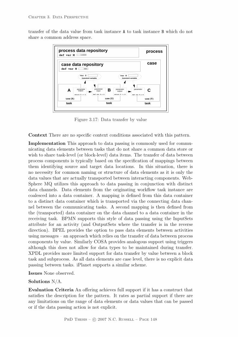
Chapter 3. Data Perspective
transfer of the data value from task instance A to task instance B which do notshare a common address space.
task
process
case data repository
process data repositorydef var M
def var N
case
var G var H
A
use(S) use(T)
B C
transient variable transient variable
use(R)
task task task
inputinput
return R −> G def var S:= G return S −> H def var T:= H
AB01
3.14159
parameter parameterparameterparameteroutput output
Figure 3.17: Data transfer by value
Context There are no specific context conditions associated with this pattern.
Implementation This approach to data passing is commonly used for commu-nicating data elements between tasks that do not share a common data store orwish to share task-level (or block-level) data items. The transfer of data betweenprocess components is typically based on the specification of mappings betweenthem identifying source and target data locations. In this situation, there isno necessity for common naming or structure of data elements as it is only thedata values that are actually transported between interacting components. Web-Sphere MQ utilizes this approach to data passing in conjunction with distinctdata channels. Data elements from the originating workflow task instance arecoalesced into a data container. A mapping is defined from this data containerto a distinct data container which is transported via the connecting data chan-nel between the communicating tasks. A second mapping is then defined fromthe (transported) data container on the data channel to a data container in thereceiving task. BPMN supports this style of data passing using the InputSetsattribute for an activity (and OutputSets where the transfer is in the reversedirection). BPEL provides the option to pass data elements between activitiesusing messages – an approach which relies on the transfer of data between processcomponents by value. Similarly COSA provides analogous support using triggersalthough this does not allow for data types to be maintained during transfer.XPDL provides more limited support for data transfer by value between a blocktask and subprocess. As all data elements are case level, there is no explicit datapassing between tasks. iPlanet supports a similar scheme.
Issues None observed.
Solutions N/A.
Evaluation Criteria An offering achieves full support if it has a construct thatsatisfies the description for the pattern. It rates as partial support if there areany limitations on the range of data elements or data values that can be passedor if the data passing action is not explicit.
PhD Thesis – c© 2007 N.C. Russell – Page 148

Chapter 3. Data Perspective
Pattern WDP-28 (Data Transfer by Value – Outgoing)
Description The ability of a process component to pass data elements to subse-quent components as values avoiding the need to have shared names or commonaddress space with the component(s) to which it is passing them.
Example
– Upon completion, the Identify Successful Applicant task passes the value ofsuccessful applicant name to the next task.
Motivation Similar to the Data Transfer by Value – Incoming pattern (WDP-27) although in this scenario, the emphasis is on minimising the coupling betweena component and the subsequent components that may receive its output data.
Overview As for the Data Transfer by Value – Incoming pattern (WDP-27).
Context There are no specific context conditions associated with this pattern.
Implementation As for Data Transfer by Value – Incoming pattern (WDP-27).
Issues None observed.
Solutions N/A.
Evaluation Criteria An offering achieves full support if it has a construct thatsatisfies the description for the pattern. It rates as partial support if there areany limitations on the range of data elements or data values that can be passedor if the data passing action is not explicit.
Pattern WDP-29 (Data Transfer – Copy In/Copy Out)
Description The ability of a process component to copy the values of a setof data elements from an external source (either within or outside the processenvironment) into its address space at the commencement of execution and tocopy their final values back at completion.
Example
– When the Review Witness Statements task commences, copy in the witnessstatement records and copy back any changes to this data at task completion.
Motivation This facility provides components with the ability to make a localcopy of data elements that can be referenced elsewhere in the process instance.This copy can then be utilized during execution and any changes that are madecan be copied back at completion. It enables components to function indepen-dently of data changes and concurrency constraints that may occur in the broaderprocess environment.
Overview The manner in which this style of data passing operates is shown inFigure 3.18.
Context There are no specific context conditions associated with this pattern.
Implementation Whilst not a widely supported data passing strategy, someofferings do offer limited support for it. In some cases, its use necessitates theadoption of the same naming strategy and structure for data elements within
PhD Thesis – c© 2007 N.C. Russell – Page 149
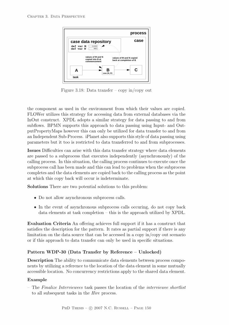
Chapter 3. Data Perspective
task instance
process
case data repositorydef var M def var N
case
A
task
use(M,N)B C
AB01
copied into B atvalues of M and N
3.14159
values of M and N copied
commencement back at completion of B
Figure 3.18: Data transfer – copy in/copy out
the component as used in the environment from which their values are copied.FLOWer utilizes this strategy for accessing data from external databases via theInOut construct. XPDL adopts a similar strategy for data passing to and fromsubflows. BPMN supports this approach to data passing using Input- and Out-putPropertyMaps however this can only be utilized for data transfer to and froman Independent Sub-Process. iPlanet also supports this style of data passing usingparameters but it too is restricted to data transferred to and from subprocesses.
Issues Difficulties can arise with this data transfer strategy where data elementsare passed to a subprocess that executes independently (asynchronously) of thecalling process. In this situation, the calling process continues to execute once thesubprocess call has been made and this can lead to problems when the subprocesscompletes and the data elements are copied back to the calling process as the pointat which this copy back will occur is indeterminate.
Solutions There are two potential solutions to this problem:
• Do not allow asynchronous subprocess calls.
• In the event of asynchronous subprocess calls occuring, do not copy backdata elements at task completion – this is the approach utilized by XPDL.
Evaluation Criteria An offering achieves full support if it has a construct thatsatisfies the description for the pattern. It rates as partial support if there is anylimitation on the data source that can be accessed in a copy in/copy out scenarioor if this approach to data transfer can only be used in specific situations.
Pattern WDP-30 (Data Transfer by Reference – Unlocked)
Description The ability to communicate data elements between process compo-nents by utilizing a reference to the location of the data element in some mutuallyaccessible location. No concurrency restrictions apply to the shared data element.
Example
– The Finalize Interviewees task passes the location of the interviewee shortlistto all subsequent tasks in the Hire process.
PhD Thesis – c© 2007 N.C. Russell – Page 150

Chapter 3. Data Perspective
Motivation This pattern is commonly utilized as a means of communicatingdata elements between process components which share a common data store. Itinvolves the use of a named data location (which is generally agreed at designtime) that is accessible to both the origin and target components and, in effect,is an implicit means of passing data as no actual transport of information occursbetween the two components.
Overview Figure 3.19 illustrates the passing of two data elements M and N (globaland case level respectively) by reference from task instance A to B. Note that taskinstance B accepts these elements as parameters to internal data elements R andS respectively.
task
processprocess data repositorydef var M
case data repositorydef var N
case
Buse(R,S)A pass(&M,&N)
task
inputparameter
3.14159
AB01
def var R:= &Mdef var S:= &N
Figure 3.19: Data transfer by reference – unlocked
Context There are no specific context conditions associated with this pattern.
Implementation Reference-based data passing requires the ability for commu-nicating process components to have access to a common data store and to utilizethe same reference notation for elements that they intend to use co-jointly. Theremay or may not be communication of the location of shared data elements viathe control channel or data channel (where supported) at the time that control-flow passes from one component to the next. This mechanism for data passingis employed within the Staffware, FLOWer, COSA and iPlanet workflow enginesand also within XPDL and BPEL.
Issues The major issue associated with this form of data utilization is that it canlead to problems where two (or more) concurrent task instances access the samedata element simultaneously. In the event that two or more of the task instancesupdate the shared data element in a short interval, there is the potential forthe “lost update problem” to arise where one of the task instances unwittinglyoverwrites the update made by another.
Solutions The solution to this issue to to provide a means of limiting concurrentaccess to shared data elements where updates to its value are required. Thereare a variety of possible solutions to this, but the use of read and write locks isthe most widely utilized scheme. The Data Transfer by Reference – With Lockpattern (WDP-31) embodies this solution.
Evaluation Criteria An offering achieves full support if it has a construct thatsatisfies the description for the pattern.
PhD Thesis – c© 2007 N.C. Russell – Page 151

Chapter 3. Data Perspective
Pattern WDP-31 (Data Transfer by Reference – With Lock)
Description The ability to communicate data elements between process compo-nents by passing a reference to the location of the data element in some mutuallyaccessible location. Concurrency restrictions are implied with the receiving com-ponent receiving the privilege of read-only or dedicated access to the data element.The required lock is declaratively specified as part of the data passing request.
Example
– At conclusion, the Allocate Client Number task passes the locations of the newclient number and new client details data elements to the Prepare InsuranceDocument task, which receives dedicated access to these data items.
Motivation As for the previous pattern, this pattern communicates data ele-ments between process components via a common data store based on commonknowledge of the name of the data location. It provides the additional ability tolock the data element ensuring that only one task can access and/or update it atany given time, thus preventing any potential update conflicts between concurrenttasks which may otherwise attempt to update it simultaneously or continue touse an old value of the data element without knowledge that it has been updated.
Overview This approach is an extension of the Data Transfer by Reference –Unlocked pattern (WDP-30) identified above in which there is also the expec-tation that the originating process component has acquired either read-only orexclusive (write) access to the specific data elements being passed (i.e. a read orwrite lock). The process component that receives these data elements can chooseto relinquish this access level (thus making them available to other process com-ponents) or it may choose to retain it and pass it on to later components. Thereis also the potential for the access level to be promoted (i.e. from a read to awrite lock) or demoted (i.e. from a write to a read lock).
Context There are no specific context conditions associated with this pattern.
Implementation This pattern is not widely implemented in the offerings exam-ined. iPlanet is the only workflow engine to directly support it. BPEL provides anapproach to concurrency control through the use of serializable scopes which allowfault and compensation handlers to be defined for groups of process activities andallow access to a given data element to be restricted to a single task instance atany given time. BPMN and UML 2.0 ADs both utilize a “token-based” approachto data passing in which data objects are consumed at task commencement andemitted at completion hence they both support this pattern. FLOWer provideslimited support for a style of write lock which allows the primary case to modifydata whilst still enabling it to be accessible for reading by other processes.
Issues None observed.
Solutions N/A.
Evaluation Criteria An offering achieves full support if it has a construct thatsatisfies the description for the pattern. It is rated as partial support if the lockingrequirement cannot be declaratively specified as part of the data passing request.
PhD Thesis – c© 2007 N.C. Russell – Page 152

Chapter 3. Data Perspective
Pattern WDP-32 (Data Transformation – Input)
Description The ability to apply a transformation function to a data elementprior to it being passed to a process component. The transformation functionhas access to the same data elements as the receiving process component.
Example
– Prior to passing the transform voltage data element to the Project demand()function, convert it to standard ISO measures.
Motivation The ability to specify transformation functions provides a means ofhandling potential mismatches between data elements and formal parameters toprocess components in a declarative manner. These functions could be internalto the process or could be externally facilitated.
Overview In the example shown in Figure 3.20, the prepare() function inter-mediates the passing of the data element G between task instances A and B. Atthe point at which control is passed to B, the results of performing the prepare()transformation function on data element G are made available to the input pa-rameter S.
task
process
var Gtransient variable
use(R) use(S)
A B
case
task
transform(R)−> Gdef var S:=
inputparameter
prepare(G)
parameteroutput
return
Figure 3.20: Data transformation – input and output
Context There are no specific context conditions associated with this pattern.
Implementation Staffware provides the ability for a task to call a functioncapable of manipulating the data elements passed to the task prior to its com-mencement through the use of the form initial facility. The function called maybe based on the Staffware script language or external 3GL capabilities and hencecan support relatively complex transformation functionality. UML 2.0 ADs sup-port data transformation via the ObjectFlow transformation behaviour. FLOWerprovides limited facilities for the transformation of input data elements throughthe use of mappings and derived elements. Similarly BPMN provide supportfor the pattern using PropertyMaps but only where the data passing is to anIndependent Sub-Process.
Issues None observed.
Solutions N/A.
Evaluation Criteria An offering achieves full support if it has a construct thatsatisfies the description for the pattern. It rates as partial support if there are
PhD Thesis – c© 2007 N.C. Russell – Page 153

Chapter 3. Data Perspective
any limitations on the type of data elements that can be passed to transformationfunctions or the range of process components that can receive values from inputtransformation functions.
Pattern WDP-33 (Data Transformation – Output)
Description The ability to apply a transformation function to a data elementimmediately prior to it being passed out of a process component. The transfor-mation function has access to the same data elements as the process componentthat initiates it.
Example
– Summarize the spatial telemetry data returned by the Satellite Download taskbefore passing it to subsequent activities.
Motivation As for the Data Transformation – Input pattern (WDP-32).
Overview This pattern operates in a similar manner to the Data Transformation– Input pattern (WDP-32) however in this case the transformation occurs at theconclusion of the task, e.g. in Figure 3.20, the transform() function is executedat the conclusion of task A immediately before the output data element is passedto data element G.
Context There are no specific context conditions associated with this pattern.
Implementation As described for the Data Transformation – Input pattern(WDP-32) except that the facilities identified are used for transforming the dataelements passed from a task instance rather than for those passed to it.
Issues None observed.
Solutions N/A.
Evaluation Criteria An offering achieves full support if it has a construct thatsatisfies the description for the pattern. It rates as partial support if there areany limitations on the type of data elements that can be passed to transformationfunctions or the range of process components that can receive values from outputtransformation functions.
3.5 Data-based routing patterns
Where as previous sections have examined characteristics of data elements inisolation from other process perspectives (i.e. control-flow, resource, etc.), thefollowing patterns capture the various ways in which data elements can interactwith other perspectives and influence the overall operation of a process instance.
Pattern WDP-34 (Task Precondition – Data Existence)
Description Data-based preconditions can be specified for tasks based on thepresence of data elements at the time of execution. The preconditions can utilizeany data elements available to the task with which they are associated. A taskcan only proceed if the associated precondition evaluates positively.
PhD Thesis – c© 2007 N.C. Russell – Page 154

Chapter 3. Data Perspective
Example
– Only execute the Run Backup task when tape loaded flag exists.
Motivation The ability to deal with missing data elements at the time of taskinvocation is desirable. This allows corrective action to be taken during processexecution rather than necessitating the raising of an error condition and haltingany further action.
Overview The operation of this pattern is illustrated in Figure 3.21. Typicallydata existence preconditions are specified on task input parameters23 in the pro-cess model as illustrated in Figure 3.21. In this context, data existence refers tothe ability to determine whether a required parameter has been defined and pro-vided to the task at the time of task invocation and whether it has been assigneda value. One of five actions is possible where missing parameters are identified:
• Defer task commencement until they are available.
• Specify default values for parameters to take when they are not available.
• Request values for them interactively from PAIS users.
• Skip this task and trigger the following task(s).
• Kill this thread of execution in the case.
taskB
use(S)
process
case
use(R)
A
task
precondition
parameteroutput
return R
parameter inputdef var S:= R
exists(R)
Figure 3.21: Task precondition – data existence
Context There are no specific context conditions associated with this pattern.
Implementation This pattern is implemented in a variety of different waysamongst the offerings examined. Staffware provides the ability to set defaultvalues for fields which do not have a value recorded for them via the initialform command facility but only for those tasks that have forms associated withthem. Conditional actions can also be specified which route control-flow around(i.e. skip) a task where required data elements are not available. FLOWer pro-vides the milestone construct which, amongst other capabilities, provides data
23For the purposes of this discussion, the term parameters is used in a general manner torefer both to data elements that are formally passed to a task and also to those that are sharedbetween a task and its predecessor and passed implicitly.
PhD Thesis – c© 2007 N.C. Russell – Page 155

Chapter 3. Data Perspective
synchronization support allowing the commencement of a subsequent task to bedeferred until nominated data elements have a value specified. COSA also pro-vides transition conditions on incoming arcs and in conjunction with the CON-DITION.TOKEN and STD tool agents, it enables the passing of control to atask to be delayed until the transition condition (which could be data elementexistence) is achieved. iPlanet supports this form of precondition using Trig-ger methods which are evaluated when a task receives the thread of control todetermine whether it can commence. BPMN supports the specification of dataexistence preconditions using the RequiredForStart attribute for Data Objects.UML 2.0 ADs allow preconditions to be specified for actions and activities usingOCL expressions. BPEL provides exception handling facilities where an attemptto utilize an uninitialized variable is detected. These can be indirectly used toprovide data existence precondition support at task level but require each taskto be defined as having its own scope with a dedicated fault handler to managethe uninitialized parameters accordingly.
Issues A significant consideration in managing preconditions that relate to dataexistence is being able to differentiate between data elements that have an unde-fined value and those that are merely empty or null.
Solutions Staffware addresses this issue by using a special value (SW NA) fordata elements that are undefined. Uninitialized fields have this value by defaultand it can be tested for in workflow expressions and conditions. FLOWer alsoprovides facilities to test whether data elements have been assigned a value. BPELprovides internal capabilities to recognize uninitialized data elements althoughthese facilities are not directly accessible to process developers. Other workflowengines examined do not differentiate between undefined and empty (or null)values.
Evaluation Criteria An offering achieves full support if it has a construct thatsatisfies the description for the pattern. It rates as partial support if the precon-dition cannot be specified declaratively as part of the task declaration.
Pattern WDP-35 (Task Precondition – Data Value)
Description Data-based preconditions can be specified for tasks based on thevalue of specific parameters at the time of execution. The preconditions canutilize any data elements available to the task with which they are associated. Atask can only proceed if the associated precondition evaluates positively.
Example
– Execute the Rocket Initiation task when countdown is 2.
Motivation The ability to specify value-based preconditions on parameters totasks provides the ability to delay execution of the task (possibly indefinitely)where a precondition is not satisfied.
Overview The operation of this pattern is similar to that in Figure 3.21 exceptthat the precondition is value-based rather than a test for data existence. Thereare three possible alternatives where a value-based precondition is not met:
• The task can be skipped and the subsequent task(s) initiated.
PhD Thesis – c© 2007 N.C. Russell – Page 156

Chapter 3. Data Perspective
• Commencement of the task can be delayed until the required preconditionis achieved.
• This thread of execution in the case can be terminated.
Context There are no specific context conditions associated with this pattern.
Implementation This pattern is directly implemented by FLOWer through themilestone construct which enables the triggering of a task to be delayed until aparameter has a specified value. Similarly COSA provides the ability to delayexecution of a task where a precondition is not met through the specification oftransition conditions based on the required data values on the incoming arc to thetask. By specifying alternate data conditions (which correspond to the negationof the required data values) on the outgoing arc from the state preceding thecontingent task to the subsequent state, it is also possible to support the skippingof tasks where data preconditions are not met. Both approaches assume thetransition conditions are specified in conjunction with the CONDITION.TOKENtool agent. iPlanet supports this form of precondition using Trigger methodswhich are evaluated when a task receives the thread of control to determinewhether it can commence. UML 2.0 ADs allow preconditions to be specified foractions and activities using OCL expressions.
In a more limited way, Staffware provides the ability to delay task executionthrough the specification of scripts which test for the required data values at taskcommencement. However, this approach is only possible for tasks which haveforms associated with them. A better solution is to use condition actions to testfor required parameters and skip the task invocation where they are not available.
XPDL provides support for a task to be skipped when a nominated data valueis not achieved through the specification of an additional edge in the workflowschema which bypasses the task in question (i.e. it links the preceding and subse-quent tasks) and has a transition condition which is the negation of the requireddata value.
A similar effect can be achieved in BPEL through the use of link conditions.By specifying a link condition to the task, call it A, which corresponds to therequired data values and creating a parallel empty task in the business processthat has a link condition that is the negation of this, task A will be skipped ifthe required data values are not detected.
Issues None identified.
Solutions N/A.
Evaluation Criteria An offering achieves full support if it has a construct thatsatisfies the description for the pattern.
Pattern WDP-36 (Task Postcondition – Data Existence)
Description Data-based postconditions can be specified for tasks based on theexistence of specific parameters at the time of task completion. The postcon-ditions can utilize any data elements available to the task with which they areassociated. A task can only proceed if the associated postcondition evaluatespositively.
PhD Thesis – c© 2007 N.C. Russell – Page 157

Chapter 3. Data Perspective
Example
– Do not complete the Rocket Initiation task until ignition data is available.
Motivation Implementation of this pattern ensures that a task cannot completeuntil specified output parameters exist and have been allocated a value.
Overview Figure 3.22 illustrates this pattern. The specification of a data-basedpostcondition on a task effectively creates an implicit decision at the end of thetask. If the postcondition is met, then the thread of control is passed to one ormore of the outgoing branches from the task (e.g. task B is enabled if the postcon-dition exists(R) is met). There is an alternate path if the postcondition is notmet back to the task. There are two possible scenarios where the postconditionis not met: either (1) the thread of control can be routed back to the beginningof the task (which may or may not result in the task being executed again) or(2) it can be routed to the end of the task (which is analogous to suspending thetask). The implication of both scenarios however, is that the task does not passon control-flow until the required parameters exist and have defined values.
task
case
B
use(S)
exists(R)
not(exists(R))option 1
process
A
use(R)
not(exists(R))
exists(R)?
option 2task
postcondition
parameter output
exists(R)
return R input
def var S:= R
parameter
Figure 3.22: Task postcondition – data existence
Context There are no specific context conditions associated with this pattern.
Implementation Two alternatives exist for the implementation of this pattern.Where tasks that have effectively finished all of their processing but have a nom-inated data existence postcondition that has not been satisfied, either the taskcould be suspended until the required postcondition is met or the task could beimplicitly repeated until the specified postcondition is met.
FLOWer provides direct support for this pattern by allowing data elementfields in task constructs, called plan elements, to be specified as mandatory, thusensuring they have a value specified before the plan element can complete execu-tion. WebSphere MQ implements this pattern through the specification of exitconditions on tasks. If the required exit condition is not met at the time taskprocessing is completed, then the task is restarted. A specific IS NULL functionis available to test if a parameter has been assigned a value. iPlanet provides theOnComplete method which can be used to defer task completion until a requireddata elements exists.
PhD Thesis – c© 2007 N.C. Russell – Page 158

Chapter 3. Data Perspective
Staffware provides indirect support through the inclusion of release scriptswith tasks which evaluate whether the required data elements have been specified.Completion of the task is deferred until the required condition is satisfied althoughthis approach is limited to tasks that have forms associated with them. SimilarlyCOSA indirectly supports this pattern through the use of condition-based triggerswhich only pass control to a subsequent task once a required data existencecondition is set.
BPMN supports the specification of data existence postconditions using theProducedAtCompletion attribute for Data Objects. UML 2.0 ADs allow post-conditions to be specified for actions and activities using OCL expressions.
Issues As for the Task Precondition – Data Existence pattern (WDP-34).
Solutions As for the Task Precondition – Data Existence pattern (WDP-34).
Evaluation Criteria An offering achieves full support if it has a construct thatsatisfies the description for the pattern. It rates as partial support if there arelimitations on the range of data elements that can be included in postconditions.
Pattern WDP-37 (Task Postcondition – Data Value)
Description Data-based postconditions can be specified for tasks based on thevalue of specific parameters at the time of execution. The postconditions canutilize any data elements available to the task with which they are associated. Atask can only proceed if the associated postcondition evaluates positively.
Example
– Execute the Fill Rocket task until rocket-volume is 100%.
Motivation Implementation of this pattern would ensure that a task could notcomplete until nominated output parameters had a particular data value or arein a specified range.
Overview Similar to the Task Postcondition – Data Existence pattern (WDP-36), two options exist for handling the achievement of specified values for dataelements at task completion:
• Delay execution until the required values are achieved.
• Implicitly re-run the task.
Context There are no specific context conditions associated with this pattern.
Implementation The implementation methods for this pattern adopted by thevarious tools examined are identical to those described for the Task Postcondition– Data Existence pattern (WDP-36) except for BPMN which does not supportvalue-based postconditions.
Issues None identified.
Solutions N/A.
Evaluation Criteria An offering achieves full support if it has a construct thatsatisfies the description for the pattern. It rates as partial support if there arelimitations on the range of data elements that can be included in postconditions.
PhD Thesis – c© 2007 N.C. Russell – Page 159

Chapter 3. Data Perspective
Pattern WDP-38 (Event-based Task Trigger)
Description The ability for an external event to initiate a task and to pass dataelements to it.
Example
– Initiate the Emergency Shutdown task immediately after the Power Alarmevent occurs and pass the alarm code data element.
Motivation This pattern is an extension of the Transient Trigger and Persis-tent Trigger patterns (WCP-23, WCP-24) which the supports the initiation orresumption of a specific task instance based on an external event. The Event-based Task Trigger pattern extends these patterns by allowing one or more dataelements to be passed to the task instance being initiated.
Overview There are three distinct scenarios that may arise in the context of thispattern as illustrated in Figure 3.23. In all situations, the capability is availableto pass data elements at the same time that the trigger is sent to the relevanttask. The first alternative (illustrated by the start A() function) is that the taskinstance to be initiated is the first task in the process. This is equivalent incontrol-flow terms to starting a new case in which A is the first task instance.
task
start_B()
start_A()
start_C()
case
externalprocess
task
BA
C
task
task
process
Figure 3.23: Event-based task trigger
The second alternative (illustrated by the start B() function) is that the ex-ternal event is triggering the resumption of a task instance that is in the middleof a process. The task instance has already had control-flow passed to it but itsexecution is suspended pending occurrence of the external event trigger. Thissituation is shown in Figure 3.23 above with task instance B already triggered asa result of task instance A completing but halted from further progress until theevent from start B() occurs.
The third alternative is that the task instance is isolated from the maincontrol-flow in the process and the only way in which it can be initiated is byreceiving an external event stimulus. Figure 3.23 shows task instance C whichcan only be triggered when the event stimulus from start C() is received.
Context There are no specific context conditions associated with this pattern.
Implementation This facility generally takes the form of an external interfaceto the process environment that provides a means for applications to trigger the
PhD Thesis – c© 2007 N.C. Russell – Page 160
Chapter 3. Data Perspective
execution of a specific task instance. All three variants of this pattern are directlysupported by Staffware, FLOWer, COSA, BPEL, BPMN and UML 2.0 ADs andin all cases, the passing of data elements as well as process triggering is supported.WebSphere MQ provides indirect support for all three variants but requires eventhandling to be explicitly coded into activity implementations.
Issues None identified.
Solutions N/A.
Evaluation Criteria An offering achieves full support if it has a construct thatsatisfies the description for the pattern. It achieves a partial support rating ifprogrammatic extensions are required to facilitate the trigger handling.
Pattern WDP-39 (Data-based Task Trigger)
Description Data-based task triggers provide the ability to trigger a specifictask when an expression based on data elements in the process instance evaluatesto true. Any data element accessible within a process instance can be used aspart of a data-based trigger expression.
Example
– Trigger the Re-balance Portfolio task when the loan margin is less than 85%.
Motivation This pattern provides a means of triggering the initiation or resump-tion of a task instance when a condition based on data elements in the processinstance is satisfied.
Overview This pattern is analogous to the notion of active rules [Har93] orevent-condition-action (ECA) rules [PD99] found in active databases [DGG95].A specific data-based trigger expression is associated with a task that is to beenabled in this way.
Context There are no specific context conditions associated with this pattern.
Implementation The pattern is directly supported in FLOWer through thespecification of a condition corresponding to the required data expression on amilestone construct immediately preceding the to-be-triggered task. When thedata condition is met, the task is then triggered. Similarly the pattern can bedirectly implemented in COSA through the use of transition conditions whichincorporate the data condition being monitored for on the incoming edges to theto-be-triggered task. Depending on the semantics required for the triggering,the transition condition may or may not include the CONDITION.TOKEN toolagent24. BPMN supports this pattern via the Rule Event construct.
Many PAIS do not directly support this pattern, however in some cases itcan be constructed for offerings that support event-based triggering (i.e. patternWDP-38) by simulating event-based triggering within the context of the processinstance. This is achieved by nominating an event that the triggered task shouldbe initiated/resumed on and then establishing a data monitoring task that runs
24If it does include this condition, the to-be-triggered task will only run when there is a tokenin the immediately preceding state and the transition condition is met. If not, the task willbecome executable whenever the transition condition is met.
PhD Thesis – c© 2007 N.C. Russell – Page 161
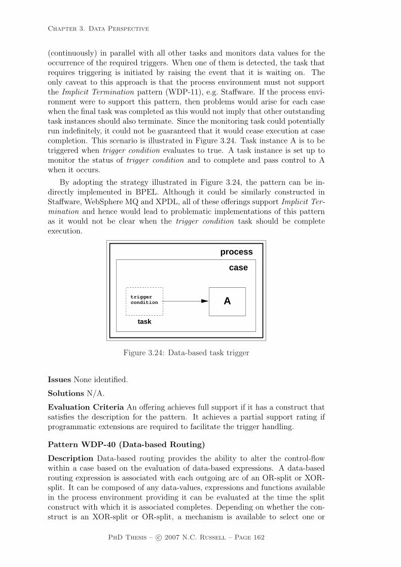
Chapter 3. Data Perspective
(continuously) in parallel with all other tasks and monitors data values for theoccurrence of the required triggers. When one of them is detected, the task thatrequires triggering is initiated by raising the event that it is waiting on. Theonly caveat to this approach is that the process environment must not supportthe Implicit Termination pattern (WDP-11), e.g. Staffware. If the process envi-ronment were to support this pattern, then problems would arise for each casewhen the final task was completed as this would not imply that other outstandingtask instances should also terminate. Since the monitoring task could potentiallyrun indefinitely, it could not be guaranteed that it would cease execution at casecompletion. This scenario is illustrated in Figure 3.24. Task instance A is to betriggered when trigger condition evaluates to true. A task instance is set up tomonitor the status of trigger condition and to complete and pass control to Awhen it occurs.
By adopting the strategy illustrated in Figure 3.24, the pattern can be in-directly implemented in BPEL. Although it could be similarly constructed inStaffware, WebSphere MQ and XPDL, all of these offerings support Implicit Ter-mination and hence would lead to problematic implementations of this patternas it would not be clear when the trigger condition task should be completeexecution.
triggercondition A
task
process
case
Figure 3.24: Data-based task trigger
Issues None identified.
Solutions N/A.
Evaluation Criteria An offering achieves full support if it has a construct thatsatisfies the description for the pattern. It achieves a partial support rating ifprogrammatic extensions are required to facilitate the trigger handling.
Pattern WDP-40 (Data-based Routing)
Description Data-based routing provides the ability to alter the control-flowwithin a case based on the evaluation of data-based expressions. A data-basedrouting expression is associated with each outgoing arc of an OR-split or XOR-split. It can be composed of any data-values, expressions and functions availablein the process environment providing it can be evaluated at the time the splitconstruct with which it is associated completes. Depending on whether the con-struct is an XOR-split or OR-split, a mechanism is available to select one or
PhD Thesis – c© 2007 N.C. Russell – Page 162

Chapter 3. Data Perspective
several outgoing arcs to which the thread of control should be passed based onthe evaluation of the expressions associated with the arcs.
Example
– If alert is red then execute the Inform Fire Crew task after the Handle Alerttask otherwise run the Identify False Trigger task.
Motivation Data-based Routing is a variant of the Exclusive Choice and Multi-Choice patterns (WCP-4, WCP-6) in the control-flow perspective which requiresthat the selection mechanism for evaluation of the pattern be based on data-based expressions evaluated using data elements available within the context ofthe process instance25.
Overview This pattern aggregates two control-flow patterns:
• Exclusive Choice – where control-flow is passed to precisely one of severalsubsequent tasks based on the evaluation of a data-based expression asso-ciated with each of the outgoing branches.
• Multi-Choice – where, depending on the outcome of a decision or the valueof an expression based on data elements, control-flow is passed to severalsubsequent task instances.
process
def var N
def var M process data repository
case
task
A
B
C
D
[R > 10]
[M > 3.0]
[N != AB01]
case data repository
3.14159
AB01
return R
parameteroutput
Figure 3.25: Data-based routing
Figure 3.25 illustrates data-based routing expressions as conditions associatedwith the control-flow branches from one task to another. These expressions canutilize task-level data passed from the completing task as well as any other dataelements that are accessible to the task. In the example shown, task C will betriggered once A completes (as the value of data element M is greater than 3.0),task D will not and task B may be triggered depending on the value of data elementR that is passed from A.
25Note that for the Data-based Routing pattern, it is a hard requirement that the routingdecision is based on the evaluation of data-based expressions whereas for the Exclusive Choiceand Multi-Choice patterns, the routing decisions be based on a variety of possible mechanismswhich may or may not be data-related.
PhD Thesis – c© 2007 N.C. Russell – Page 163

Chapter 3. Data Perspective
Context There is one context condition associated with this pattern: the mech-anism that evaluates the Data-based Routing is able to access any required dataelements when determining which of the outgoing branches the thread of controlshould be passed.
Implementation Both the Exclusive Choice and Multi-Choice variants of thisconstruct are supported by WebSphere MQ, COSA, iPlanet, XPDL, BPEL,BPMN and UML 2.0 ADs. Staffware and FLOWer only support the ExclusiveChoice pattern.
Issues None identified.
Solutions N/A.
Evaluation Criteria Full support for this pattern is demonstrated by any of-fering which provides a construct which satisfies the description when used in acontext satisfying the context assumption. It rates as partial support if only onevariant of the pattern is supported.
3.6 Survey of data patterns support
This section presents the results of a detailed evaluation of support for the 40Data Patterns described above by nine PAIS and business process modellinglanguages. A broad range of offerings were chosen for this review in order tovalidate the applicability of each of the patterns to various types of offerings. Aspreviously, a three point scale assessment scale is used indicating direct support(+), partial support (+/–) or no support (–) for each pattern. The specific PAISand business process modelling languages evaluated were:
• Staffware Process Suite version 926 [Sta02a, Sta02b];
• IBM WebSphere MQ Workflow 3.4 [IBM03a, IBM03b];
• FLOWer 3.0 [WF04];
• COSA 4.2 [TRA03, TRA03];
• Sun ONE iPlanet Integration Server 3.1 [Sun03];
• XPDL 1.0 [Wor02];
• BPEL 1.1 [ACD+03]
• BPMN 1.0 [OMG06]; and
• UML 2.0 ADs [OMG05].
Table 3.1 lists the first set of results which relate to the various levels of dataconstruct visibility supported within the offering. As a general rule, it can be seen
26Although not the latest version, the functionality from a data perspective is representativeof the latest offering.
PhD Thesis – c© 2007 N.C. Russell – Page 164

Chapter 3. Data Perspective
that individual products tend to favour either a task-level approach to managingproduction data and pass data elements between task instances or they use ashared data store at block or case level. The only exceptions to this being COSAand BPMN which fully support data at both levels (COSA also provides theability to share data elements on a selective basis across multiple cases).
Nr Pattern Sta
ffw
are
Web
Spher
eM
Q
FLO
Wer
CO
SA
iPla
net
XP
DL
BP
EL
BP
MN
UM
LA
Ds
1 Task Data – +/– +/– + +/– – +/– + +/–
2 Block Data + + + + + + – + +3 Scope Data – – +/– – – – + – –4 Multiple Instance Data +/– + + + + + – +/– +5 Case Data +/– + + + – + + + –6 Folder Data – – – + – – – – –7 Global Data + + – +/– – +/– – – +8 Environment Data + +/– + + + – + – –
Table 3.1: Support for data visibility patterns
A similar result can be observed for global and environment data with mostofferings fully supporting one or the other. The implication of this generally beingthat globally accessible data can either be stored in the system or outside of it(i.e. in a database). XPDL and BPMN are the exceptions although this outcomeseems to relate more to the fact that there is minimal consideration for globaldata facilities within these specifications.
Table 3.2 lists the results for internal data interaction. All offerings supporttask-to-task interaction and provide some degree of support for block task-to-subprocess interaction27. The notable omissions here are the general lack of sup-port for handling data passing to multiple instance tasks (FLOWer and UML 2.0ADs being the exceptions) and the general lack of integrated support for datapassing between cases (other than COSA).
Nr Pattern Sta
ffw
are
Web
Spher
eM
Q
FLO
Wer
CO
SA
iPla
net
XP
DL
BP
EL
BP
MN
UM
LA
Ds
9 between Tasks + + + + + + + + +10 Block Task to Subproc. + + +/– +/– + + – +/– +11 Subproc to Block Task + + +/– +/– + + – +/– +12 to Multiple Instance Task – – + – – – – – +13 from Multiple Instance Task – – + – – – – – +14 Case to Case +/– +/– +/– + +/– +/– +/– – –
Table 3.2: Support for internal data interaction patterns
27BPEL being the exception given its lack of support for subprocesses.
PhD Thesis – c© 2007 N.C. Russell – Page 165
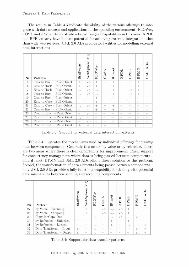
Chapter 3. Data Perspective
The results in Table 3.3 indicate the ability of the various offerings to inte-grate with data sources and applications in the operating environment. FLOWer,COSA and iPlanet demonstrate a broad range of capabilities in this area. XPDLand BPEL clearly have limited potential for achieving external integration otherthan with web services. UML 2.0 ADs provide no facilities for modelling externaldata interactions.
Nr Pattern Sta
ffw
are
Web
Spher
eM
Q
FLO
Wer
CO
SA
iPla
net
XP
DL
BP
EL
BP
MN
UM
LA
Ds
15 Task to Env. – Push-Orient. + +/– + + + + + + –16 Env. to Task – Pull-Orient. + +/– + + + + + + –17 Env. to Task – Push-Orient. +/– +/– +/– + + – +/– + –18 Task to Env. – Pull-Orient. +/– +/– +/– + + – +/– + –19 Case to Env. – Push-Orient. – – + – – – – – –20 Env. to Case – Pull-Orient. – – + – – – – – –21 Env. to Case – Push-Orient. +/– +/– + + + – – – –22 Case to Env. – Pull-Orient. – – + + + – – – –23 Proc. to Env. – Push-Orient. – +/– – – – – – – –24 Env. to Proc. – Pull-Orient. +/– – – – – – – – –25 Env. to Proc. – Push-Orient. – +/– – – – – – – –26 Proc. to Env. – Pull-Orient. + + – + – – – – –
Table 3.3: Support for external data interaction patterns
Table 3.4 illustrates the mechanisms used by individual offerings for passingdata between components. Generally this occurs by value or by reference. Thereare two areas where there is clear opportunity for improvement. First, supportfor concurrency management where data is being passed between components –only iPlanet, BPMN and UML 2.0 ADs offer a direct solution to this problem.Second, the transformation of data elements being passed between components –only UML 2.0 ADs provide a fully functional capability for dealing with potentialdata mismatches between sending and receiving components.
Nr Pattern Sta
ffw
are
Web
Spher
eM
Q
FLO
Wer
CO
SA
iPla
net
XP
DL
BP
EL
BP
MN
UM
LA
Ds
27 by Value – Incoming – + – +/– +/– +/– + + –28 by Value – Outgoing – + – +/– +/– +/– + + –29 Copy In/Copy Out – – +/– – +/– +/– – +/– –30 by Reference – Unlocked + – + + + + + – –31 by Reference – Locked – – +/– – + – +/– + +32 Data Transform. – Input +/– – +/– – – – – +/– +33 Data Transform. – Output +/– – +/– – – – – +/– +
Table 3.4: Support for data transfer patterns
PhD Thesis – c© 2007 N.C. Russell – Page 166

Chapter 3. Data Perspective
Table 3.5 indicates the ability of the data perspective to influence the con-trol perspective within each offering. FLOWer and UML 2.0 ADs demonstrateoutstanding capability in this area and Staffware, WebSphere MQ, iPlanet andCOSA also have relatively good integration of the data perspective with control-flow although each of them (other than iPlanet) lack some degree of task pre andpostcondition support. Similar comments apply to XPDL which has significantlymore modest capabilities in this area and completely lacks any form of triggersupport. BPEL would also benefit from better pre and postcondition supportand lacks data-based triggering.
Nr Pattern Sta
ffw
are
Web
Spher
eM
Q
FLO
Wer
CO
SA
iPla
net
XP
DL
BP
EL
BP
MN
UM
LA
Ds
34 Task Precond. – Data Exist. + – + + + – +/– + +35 Task Precond. – Data Value + – + + + + + – +36 Task Postcond. – Data Exist. +/– + + – + – – + +37 Task Postcond. – Data Value +/– + + – + – – – +38 Event-based Task Trigger + +/– + + – – + + +39 Data-based Task Trigger – – + + – – +/– + –40 Data-based Routing +/– + +/– + + + + + +
Table 3.5: Support for data routing patterns
Several observations are worthy of note from these results in regard to thecapabilities and shortcomings of existing offerings. One of the most immediate isthat the level of direct support for Data Patterns in existing process design toolsis minimal. These tools focus largely on the definition of process structures andtheir associated components in a graphical form. Support for the data perspectiveis typically fragmented and distributed across various parts of the overall processmodel. This situation is partially explained by the graphical nature of control-flowand its primacy as a means of process modelling. Although there are graphicalmeans of characterising the information contained in the data perspective (e.g.ER diagrams, class diagrams, object-role models), these are not widely utilizedin current design tools and there is clearly a need for better support in capturingthe integration between the control-flow and data perspectives at design time.
Another observation is that many systems/standards do not offer support formultiple instance tasks. These constructs serve as an effective model of con-currency where the underlying activities are largely based on a common set ofactions. From a data perspective, this pattern is quite demanding and thereare a number of considerations associated with its implementation although formany of the offerings examined it would constitute a useful addition to currentmodelling and implementation constructs.
A number of the offerings examined implement a shared repository for dataelements (at block, scope, case, folder or global level) where tasks access a com-mon set of data elements rather than passing them between tasks. Whilst thisapproach has advantages from a performance standpoint and improves the overalltractability of process models, it is surprising how few of them offer an effective
PhD Thesis – c© 2007 N.C. Russell – Page 167

Chapter 3. Data Perspective
means of concurrency control for shared data. Indeed, the maturity of the datarepresentation supported by all of the offerings examined is well short of the stateof the art in database technology. There is an evident lack of support for com-plex data structures, minimal capabilities for specifying relationships betweencases and their associated data elements and a notable lack of streamlined facili-ties for interacting with the external environment in the variety of ways that thecontemporary corporate application environment requires.
3.7 Related work
Although the data perspective is deemed to be an essential part of a businessprocess model [JB96, LR00], it is interesting to observe that most PAIS onlyprovide minimal support for persistent data with long term storage generally be-ing delegated to external applications with facilities being provided to read inand write out data as required during process execution. The WfMC providesa classification [Wor99] of runtime data which is relevant to PAIS more gener-ally in which it distinguishes three types of data: (1) application data whichrepresents data objects manipulated by external applications during process en-actment which is not directly relevant to the control-flow of the process and isgenerally not accessible by the PAIS, (2) workflow relevant data which is used todetermine control-flow and may flow through a process instance during executionand (3) workflow control data which is produced during process execution andis not accessible outside of the PAIS – typically this includes state informationsuch as enabled tasks, data values and work lists as well as audit trails capturingexecution history.
The lack of sophistication inherent in the data perspective is reflected by therelative paucity of research in this area and research initiatives tend to focus onone of two topics: (1) improving the manner in which data is trafficked withinthe PAIS or between it and other applications and (2) increasing the resilience ofthe PAIS against potential data corruption.
There are three general approaches to data flow within PAIS [SOSF04]: (1)data flow transitions can be explicitly defined as part of the process model, (2)data flow between tasks can occur implicitly in conjunction with control-flow and(3) data flow can occur implicitly between tasks through a shared data store.For each of these approaches, data elements can be passed individually, typicallybeing specified as parameters to or from a task (e.g. as occurs in MOBILE [JB96])or these can be passed in aggregate between tasks using the notion of “containers”[LR00] which provide a means of managing the passing of a set of data elementsfrom one task to another. The issue of synchronizing internal process data withexternal data repositories is considered by Eder and Lehmann [EL05] and theypropose an architecture that allows policies to be specified for individual dataelements that identifies how changes in the value of the data element either inthe external repository or the workflow will be propagated. Analogous to thisissue is the warehousing of workflow audit data which has received significantfocus in the literature. Bonifati et al. [BCDS01] present a high level architecturefor extracting the required data to a warehouse and providing reporting facilitieson it. Zur Muehlen [Mue01] takes a similar approach although in this case,
PhD Thesis – c© 2007 N.C. Russell – Page 168
Chapter 3. Data Perspective
the focus is on using the warehouse data for process controlling and no specificdetails are presented on the way in which the data is migrated or the structureof the resultant data warehouse. A similar problem is tackled by Eder et al.[EOG02] and in this case, a schema is presented for the data warehouse alongwith experiential results obtained from building the warehouse and using it toexamine real data. Finally Schiefer et al. [SJB03] presents an architecture aimedat the real-time integration of workflow audit data into the data warehouse suchthat it can be used for process control purposes.
Research aimed at protecting the integrity of data in PAIS includes Wu etal.’s [WSML02] which proposes a comprehensive access control scheme for datain workflow systems which takes factors including the requesting user, role, taskand associated constraints and privileges into account when making decisions towhether to allow access to specific data elements. The issue of data validation isinvestigated by Sadiq et al. [SOSF04] and seven distinct data problems that canprevent a process from functioning correctly are identified. The area of trans-actional workflow [RS95b, WS97, AAA+96] has been a major area of researchaiming to adapt the benefits of classic ACID data transactions to long durationprocess environments. Ultimately this had led to the development of exceptionhandling strategies (e.g. [HA00, SMA+98, CCPP99]) that allow process failure tobe effectively managed and their impact on data resources to be minimized.
3.8 Summary
This chapter has identified 40 Data Patterns which describe the manner in whichdata elements are defined and utilized in PAIS. Validation of the applicability ofthese patterns has been achieved through a detailed review of nine contemporaryofferings in this area. All of the data patterns have been observed in some form inthe offerings examined, reinforcing their use in describing desirable characteristicsfor the data perspective in PAIS. In addition to providing a taxonomy of datacharacteristics, the patterns also serve as a useful benchmark of the state of theart in current offerings. Whilst all of the offerings examined provide some degreeof support for the data perspective, it is interesting to observe that a numberof fundamental issues which have been thoroughly addressed in other areas ofthe information systems discipline have not yet found their way into widespreadadoptance in PAIS. Issues such as providing data support for concurrent activi-ties, managing data consistency in a highly concurrent process environment andsupporting complex, structured data elements required by contemporary busi-ness processes are areas that require further consideration if PAIS are to assist instreamlining and expediting business process execution.
PhD Thesis – c© 2007 N.C. Russell – Page 169

Chapter 4. Resource Perspective
Chapter 4
Resource Perspective
Existing languages and tools focus on control-flow and combine this focus withmature support for data in the form of XML and database technology (often pro-vided by third party tools). As a result, control-flow and data management arewell-addressed by existing languages and systems (either directly or indirectlyby incorporating external capabilities). Unfortunately, less attention has beendevoted to the resource perspective. This continues to be the case even with rela-tively recent advances such as BPEL which does not provide any degree of directsupport for resources in business processes based on web-services. Similarly, lan-guages like XPDL [Wor02], the “Lingua Franca” proposed by the Workflow Man-agement Coalition (WfMC), has a very simplistic view of the resource perspectiveand provides minimal support for modelling workers, organizations, work distri-bution mechanisms, etc. John Seely Brown (a former Chief Scientist at Xerox)succinctly captures the current predicament: “Processes don’t do work, peopledo!”. In other words, it is not sufficient to simply focus on control-flow and dataissues when capturing business processes, the resources that enable them need tobe considered as well.
This chapter focuses on the resource perspective. The resource perspectivecentres on the modelling of resources and their interaction with a PAIS. Resourcescan be human (e.g. a worker) or non-human (e.g. plant and equipment), althoughour focus will only be on human resources. Although PAIS typically identifyhuman resources, they know very little about them. For example, in a workflowsystem like Staffware a human resource is completely specified by the work queues(s)he can see. This does not do justice to the capabilities of the people using suchsystems. Staffware also does not leave a lot of “elbow room” for its users sincethe only thing users can do is to execute the work items in their work queues, i.e.,people are treated as automatons and have little influence over the way work isdistributed. The limitations of existing systems triggered the research presentedin this chapter. The following sections discuss the range of Resource Patterns thathave been identified in PAIS and business process modelling languages. Theseare grouped into a series of specific categories depending on the specific focus ofindividual patterns as follows:
Creation patterns which describe design-time work distribution directives thatare nominated for tasks in a process model;
PhD Thesis – c© 2007 N.C. Russell – Page 170

Chapter 4. Resource Perspective
Push patterns which describe situations where the system proactively distrib-utes work items to resources;
Pull patterns which relate to situations where individual resources take theinitiative in identifying and committing to undertake work items;
Detour patterns which describe various ways in which the distribution andlifecycle of work items can deviate from the directives specified for them atdesign time;
Auto-start patterns which identify alternate ways in which work items can beautomatically started;
Visibility patterns which indicate the extent to which resources can observepending and executing work items; and
Multiple resource patterns which identify situations where the correspon-dence between work items and resources is not one-one.
Before moving onto a detailed discussion of the individual patterns, it is firstnecessary to introduce the notion of an organizational model and the manner inwhich it is used for distributing work items to resources.
4.1 Organizational modelling
Business processes are generally assumed to be defined in the context of an orga-nization and to utilize resources within the organization in order to complete thetasks that the business process is made up of. Hence (other than for fully auto-mated processes) there is usually an organizational model associated with eachbusiness process that describes the overall structure of the organization in whichit operates, and captures details of the various resources and the relationshipsbetween them that are relevant to the conduct of the business process.
For the purposes of this research, a resource is considered to be an entitythat is capable of doing work. Although resources can be either human or non-human (e.g. plant and equipment), in the context of this thesis, which is basedon business processes involving proactive entities that make decisions about thework that they will undertake and when they will do it, only human resources areconsidered. Work is usually assigned to a resource in the form of work items, eachof which describe an integral unit of work that the resource should undertake.Each work item corresponds to a specific task in a process model (and for thisreason work items are sometimes referred to as task instances). Users usuallyreceive notification of work items distributed to them via a worklist handler, asoftware application that provides them with a view of their work items andsupports their interaction with the system managing overall process execution.Depending on the sophistication of this application, users may have one or severalwork queues assigned to them through which work items are distributed. Theymay also be provided with a range of facilities for managing work items assignedto them through to completion.
PhD Thesis – c© 2007 N.C. Russell – Page 171

Chapter 4. Resource Perspective
A human resource is assumed to be a member of an organization. An organi-zation is a formal grouping of resources that undertake work items pertaining toa common set of business objectives. They usually have a specific job within thatorganization and in general, most organizational characteristics that resourcespossess relate to the position(s) that they occupy rather than directly to the re-source themselves. There are two sets of characteristics that are exceptions tothis rule however: roles and capabilities.
Roles serve as another grouping mechanism for human resources with sim-ilar job roles or responsibility levels, e.g. managers, union delegates etc. Eachresource may have one or more corresponding roles. Individual resources mayalso possess capabilities or attributes that further clarify their suitability for var-ious kinds of work. These may include qualifications and skills as well as otherjob-related or personal attributes such as specific responsibilities held or previouswork experience.
Each job is attached to an organizational group which are permanent groupsof human resources within the organization that undertake work items relatingto a common set of business objectives. Similarly it may also be a member of oneor more organizational teams. These are similar to organizational units but notnecessarily permanent in nature. Each job is generally associated with a specificbranch which defines a grouping of resources within the organization at a specificphysical location. It may also belong to a division which defines a large scalegrouping of resources within an organization either along regional geographic orbusiness purpose lines.
In terms of the organizational hierarchy, each job may have a number ofspecific relationships with other jobs. Their direct report is the resource to whomthey are responsible for their work. Generally this is a more senior resourceat a higher organizational level. Similarly, a job may also have a number ofsubordinates for whom they are responsible and to who each of them report.
Figure 4.1 depicts the major characteristics of a resource as described above inthe form of an Object Role Model (ORM) [Hal01] diagram. Whilst this organiza-tional model is not definitive in terms of the range of organizational concepts andrelationships that it captures (and a variety of meta-models have been proposedfor organizational modelling, e.g. [UKMZ98, FBGL97, Mue99b]), it contains suf-ficient detail to encompass the wide variety of ways in which work items arerouted to resources during process enactment. Indeed, several PAIS have beenexamined in the context of this research. Most of these utilize an internal orga-nizational model to identify resources and represent the relationships that existbetween them. In all cases, the organizational model used employs a subset ofthe concepts identified in Figure 4.1.
• Staffware [Sta02a, Sta02b] has a relatively simple model that denotes users(i.e. individual resources), groups and roles, and allows work to be assignedon the basis of these groupings. The use of roles is somewhat restrictive aseach role can only be undertaken by a single user.
• WebSphere MQ Workflow [IBM03a, IBM03b] provides a richer model thatallows users to be described in a broader organizational context (e.g. orga-nizational unit, branch, division to which they belong, who their manager
PhD Thesis – c© 2007 N.C. Russell – Page 172

Chapter 4. Resource Perspective
Figure 4.1: Organizational meta-model
is). It also supports roles and there can be a many – many correspondencebetween users and roles. Work items can be assigned to users based onvarious characteristics of the organizational model.
• FLOWer [WF04] supports an organizational model that is exclusively role-based and is defined in terms of a role hierarchy. Correspondences areestablished between individual users or groups of users and roles. All workallocations are role-based.
• COSA [TRA03] provides an organizational model that embodies many ofthe human resource concepts from Figure 4.1. Users can be defined andorganized into groups and hierarchies of groups are supported. Additionallyboth individual users and groups can be assigned roles and there is provisionfor the identification of group supervisors. Competencies can be identifiedfor individual workflow users. Work items can be routed to users using anyof these concepts.
• iPlanet [Sun03] has a minimal organizational model that allows for theidentification of users and assignment of roles to users. There is also supportfor extended user profiles that allow attributes to be used in the allocationof work to users.
• UML 2.0 Activity Diagrams [OMG05] and BPMN [OMG06] do not explic-itly define an organizational model although “swimlanes” can be used toidentify users individually or to group them together for task assignmentpurposes.
PhD Thesis – c© 2007 N.C. Russell – Page 173

Chapter 4. Resource Perspective
• BPEL [ACD+03] does not support an explicit organizational model howeverextensions to BPEL provided by some implementations (e.g. Oracle BPEL[Mul05]) provide an organizational structure which can be used for routingwork items to resources. Moreover the BPEL4People [KKL+05] extensionthat has recently been proposed is an attempt to provide further supportin this area.
4.2 Work distribution to resources
Of particular interest from a resource perspective is the manner in which workitems are distributed and ultimately bound to specific resources for execution.Figure 4.2 illustrates the lifecycle of a work item in the form of a state transitiondiagram from the time that a work item is created through to final completionor failure. It can be seen that there are a series of potential states that comprisethis process.
S:createcreated allocated to a
single resourcecompletedstarted
suspended
failed
R:complete
single resourceoffered to a
offered to multiple
resources
S:offer_m
S:allocate
R:allocate_s
R:start_m
R:start_s
R:resume
R:start
R:failR:allocate_m
S:offer_s R:suspend
Figure 4.2: Basic work item lifecycle
Initially a work item comes into existence in the created state. This indicatesthat the preconditions required for its enablement have been satisfied and it iscapable of being executed. At this point however, the work item has not beenallocated to a resource for execution and there are a number of possible pathsthrough these states that individual work items may take. Each edge within thisdiagram is prefixed with either an S or an R indicating that the transition isinitiated by the system (i.e. the software environment in which instances of theprocess execute) or resource (i.e. an actual user) respectively.
Transitions from the created state are typically initiated by the system. Theycentre on the activity of making resources aware of work items that require exe-cution. This may occur in one of three distinct ways denoted by the subsequentstates. A work item may be offered to a single resource meaning that the systeminforms exactly one resource about the availability of a work item. It may do thisby sending a message to the resource or adding the work item to the list of avail-able work items that the resource can view. Inherent in this is the notion of thesystem selecting a specific resource to which the work item should be advertised.This may occur in a variety of different ways – the process model may includespecific directives about the identity of the resource to which a given work item
PhD Thesis – c© 2007 N.C. Russell – Page 174

Chapter 4. Resource Perspective
should be directed or it may be based on more general requirements such as uti-lizing the least busy, cheapest or most appropriately qualified resource. In eachof these situations, there is the need to determine which resources are suitableand available to undertake the work item and then to rank them and select themost appropriate one.
An alternative to this course of action is indicated by the state offered tomultiple resources, where the system informs multiple resources of the existenceof a work item. Again the notion of resource selection applies, however in thiscase, the system informs all suitable resources of the work item. It does notattempt to identify which of them should undertake it.
The allocated to a single resource state denotes a work item which a specificresource has committed to executing at some time in the future. A work itemmay progress to this state either because the system pre-emptively allocates newlycreated work items to a resource or because a resource volunteers to undertake awork item that has been offered.
Note that the work item lifecycle illustrated in Figure 4.2 assumes that a workitem is undertaken by a single resource, thus there is not a state which correspondsto “allocated to multiple resources”. As discussed in [AK01], systems typicallydo not support allocation of work items to a group of resources (i.e. a team).One possible means of working around this constraint is to designate a resourcethat acts as a proxy for the team. By doing so, it is possible to approximate thedesired behaviour.
Subsequent states in the work distribution model are started, which indicatesthat a resource has commenced executing the work item, suspended which denotesthat the resource has elected to cease execution of the work item for a period,but does intend to continue working on it at a later time, failed which identifiesthat the work item cannot be completed and that the resource will not work on itany further and completed which identifies a work item that has been successfullyexecuted to completion.
4.3 Creation patterns
Creation patterns correspond to limitations on the manner in which a work itemmay be executed. They are specified at design time, usually in relation to a task,and serve to restrict the range of resources that can undertake work items thatcorrespond to the task. They also influence the manner in which a work item canbe matched with a resource that is capable of undertaking it.
The essential rationale for creation patterns is that they provide a degreeof clarity about how a work item should be handled after creation during theoffering and allocation stages prior to it being executed. This ensures that theoperation of a process conforms with its intended design principles and operatesas efficiently and deterministically as possible.
In terms of the work item lifecycle, creation patterns come into effect at thetime a work item is created. This state transition occurs at the beginning of thework item lifetime and is illustrated by the bold arrow in Figure 4.3. For all
PhD Thesis – c© 2007 N.C. Russell – Page 175

Chapter 4. Resource Perspective
of these patterns it is assumed that there is an associated organizational modelwhich allows resources to be uniquely identified and that there is a mechanism todistribute work items to specific resources identified in the organizational model.As creation patterns are specified at design time, they usually form part of theprocess model which describes a business process.
S:createcreated allocated to a
single resourcecompletedstarted
suspended
failed
R:complete
single resourceoffered to a
offered to multiple
resources
S:offer_m
S:allocate
R:allocate_s
R:start_m
R:start_s
R:resume
R:start
R:failR:allocate_m
S:offer_s R:suspend
Figure 4.3: Creation patterns
Pattern WRP-1 (Direct Distribution)
Description The ability to specify at design time the identity of the resource(s)to which instances of this task will be distributed at runtime.
Example
– The Fix Bentley task must only be undertaken by Fred.
Motivation Direct Distribution offers the ability for a process designer to pre-cisely specify the identity of the resource to which instances of a task will bedistributed at runtime. This is particularly useful where it is known that a taskcan only be effectively undertaken by a specific resource as it prevents the prob-lem of unexpected or non-suitable resource distributions arising at runtime byensuring work items are routed to specific resources, a feature that is particularlydesirable for critical tasks.
Overview The Direct Distribution pattern is specified as a relationship betweena task and a (non-empty) group of resources. At runtime, work items associatedwith the task are distributed to one or more of these resources.
Context There are no specific context conditions associated with this pattern.
Implementation Most PAIS offer some form of support for Direct Distributionof tasks to specific resources. In most cases, the distribution is to a single re-source, however Staffware allows a work item to be allocated to a series of specificresources (achieved by specifying the names of multiple resources for potentialallocation) and at runtime, the work item is routed to all of these resources andeach of them is required to release it before the work item can be deemed to havefinished and the case can progress.
Issues One of the main drawbacks of this approach to work distribution is thatit effectively defines a static binding of all work items associated with a task to
PhD Thesis – c© 2007 N.C. Russell – Page 176

Chapter 4. Resource Perspective
a single resource. This removes much of the advantage associated with the useof process technology for managing work distribution as the PAIS is offered littlelatitude for optimizing the distribution of work items in this situation.
Solutions There is no real solution to this problem although the use of deadlineand escalation mechanisms offer ways of ensuring that situations are detectedwhere a specific resource becomes overloaded and cannot deal with its assignedworkload in a reasonable timeframe.
Evaluation Criteria An offering achieves full support if it satisfies the descrip-tion for the pattern.
Pattern WRP-2 (Role-based Distribution)
Description The ability to specify at design-time one or more roles to whichinstances of this task will be distributed at runtime. Roles serve as a means ofgrouping resources with similar characteristics. Where an instance of a task isdistributed in this way, it is distributed to all resources that are members of therole(s) associated with the task.
Example
– Instances of the Approve Travel Permit task must be executed by a Manager.
Motivation Perhaps the most common approach to work item distribution with-in PAIS, Role-based Distribution offers the means for the PAIS to route work itemsto suitably qualified resources at runtime. The decision as to which resource actu-ally receives a given work item is deferred until the moment at which it becomes“runnable” and requires a resource distribution in order for it to proceed. Theadvantage offered by Role-based Distribution (over other work item distributionschemes) is that roles can be defined for a given process that identify the variousclasses of available resources to undertake work items. Task definitions withinthe process model can nominate the specific role to which they should be routed,however the actual population of individual roles occurs at runtime.
Overview The Role-based Distribution pattern is specified as a relationship be-tween a task and a (non-empty) group of roles. At runtime, work items associatedwith the task are distributed to one or more of the resources participating in theseroles.
Context There are no specific context conditions associated with this pattern.
Implementation All of the offerings examined support Role-based Distributionin some form. Generally roles serve as groupings of resources with similar char-acteristics or authority and provide a means of decoupling the routing of a workitem from that of resource management. The most restrictive approach to roledefinition occurs in Staffware where only one resource can be identified for eachrole although it is possible to specify multiple roles when defining the routing of awork item. WebSphere MQ allows multiple resources to be specified for each roleand also multiple roles to be used when routing a work item. iPlanet supportsroles in a similar way although the actual mechanism used for work item distri-bution takes the form of an expression which includes the various roles ratherthan simply listing the roles to which the work item will be forwarded. COSA
PhD Thesis – c© 2007 N.C. Russell – Page 177

Chapter 4. Resource Perspective
also uses roles as a grouping mechanism for resources and allows them to be usedas a routing mechanism for work items, however where a work item is routed tomultiple resources, it appears on a shared (group) work queue rather than beingreplicated on the work lists of individual resources. COSA provides support forexplicitly representing quite complex organizational structures and work distri-bution mechanisms by allowing role, organizational and authorization hierarchiesto be distinctly modelled and drawn together where required in the distributionfunctions for individual work items. FLOWer supports multiple users per roleand allows a user to play different roles in distinct cases. Roles serve as the mainbasis of work item distribution although resources have a reasonable degree ofautonomy in selecting the work items (and cases) that they will undertake ratherthan having work items directly assigned to them. BPMN and UML 2.0 ADssupport roles through the use of pools and swimlane constructs. Oracle BPELsupports the pattern although it does not differentiate between roles and groupsand a work item distributed to a role is visible in the worklist of all members ofthat role.
Issues In some PAIS, the concepts of roles and groups are relatively synonymous.Roles serve as an abstract grouping mechanism (i.e. not just for resources withsimilar characteristics or authority, but also for identification of organizationalunits, (e.g. teams, departments etc.) and provide a means of distributing workacross a number of resources simultaneously. One difficulty that arises with thisuse of roles occurs where the intention is to offer a work item to several resourceswith the expectation that they will all work on it.
Solutions Staffware provides support for group-based work distribution. It oper-ates in much the same way as Role-based Distribution with groups being identifiedwithin the workflow system consisting of several resources. Individual resourcesmay belong to more than one group (unlike the situation with roles) and a taskwithin the process model can be specified as requiring routing to a specific groupat runtime. However the operation of group-based distribution differs from Role-based Distribution at runtime with a work item that is allocated to a group beingvisible to all of the resources in the group and not specifically (and privately)assigned to one of them during the allocation process. Group-based distributionis non-deterministic with respect to resources and the work item is ultimatelyallocated to the first resource in the group that commences work on it. Fromthis point, none of the other resources in the group can execute it although itremains in the work queue of all of the resources until it has been completed. Asindicated above, Oracle BPEL does not differentiate between roles and groups,however only one of the users corresponding to a given role can actually under-take a work item where it is subject to role-based distribution. None of the otherofferings examined provide support for this approach to work distribution.
Evaluation Criteria An offering achieves full support if it satisfies the descrip-tion for the pattern.
Pattern WRP-3 (Deferred Distribution)
Description The ability to specify at design-time that the identification of theresource(s) to which instances of this task will be distributed will be deferreduntil runtime.
PhD Thesis – c© 2007 N.C. Russell – Page 178
Chapter 4. Resource Perspective
Example
– Identification of who will execute the Assess Damage task is deferred until run-time. During execution of a case, the next resource field will hold the identityof the resource to whom instances of the task should be allocated.
Motivation Deferred Distribution takes the notion of indirect work distributionone step further and allows the process designer to defer the need to identifythe resource for a specific task (or work items corresponding to the task) untilruntime. One means of achieving this is to nominate a data field from which theidentity of the resource to which a work item should be routed can be determinedat runtime. The identity of the resource can be changed dynamically duringprocess execution by updating the value of the data field, thus varying the resourceallocation of future work items which are contingent on it.
Overview The Deferred Distribution pattern is specified as a relationship be-tween a task and a (non-empty) group of data elements. Each data element isassumed to hold either a resource or role name. At runtime, when an instanceof the task is triggered, the values of the data element(s) is retrieved and areaggregated to give a set of resources to which work item(s) associated with thetask may be distributed. The work item(s) is then distributed to these resources.
Context There is one context condition associated with this pattern: the offeringsupports direct or role-based distribution.
Implementation This approach to work distribution is generally achieved byassociating the name(s) of the data element which will contain the resource iden-tity with the task at design-time. In order to facilitate this, the name needs tobe a data element within the scope of the task at runtime – usually a case leveldata element. It is possible that more than one data element (and hence morethan one resource) could be taken into account when deciding on the allocationat runtime. Staffware, WebSphere MQ and Oracle BPEL directly support thispattern.
Issues Two significant issues arise in implementing this pattern:
• Determining whether the value in the data field relates to a specific re-source, group or role name. This determination is important as it variesthe approach taken to work distribution.
• Ensuring that the data field contains a valid resource identity.
Solutions The first of these issues is usually addressed by ensuring that thenames used for specific resources, groups and roles are disjoint. This means thata name cannot be used in more than one context and hence there is no potentialfor ambiguity at runtime.
The second issue is more problematic as a data element can potentially containany value and there is no means of ensuring that it corresponds to an actualresource in the organizational model or to specify the action to take when theresource name is invalid. A means of handling this issue via exceptions is discussedin Chapter 5
PhD Thesis – c© 2007 N.C. Russell – Page 179

Chapter 4. Resource Perspective
Evaluation Criteria Full support for this pattern is demonstrated by any of-fering which provides a construct which satisfies the description when used in acontext satisfying the context assumption.
Pattern WRP-4 (Authorization)
Description The ability to specify the range of privileges that a resource pos-sesses in regard to the execution of a process. In the main, these privileges definethe range of actions that a resource can initiate when undertaking work itemsassociated with tasks in a process.
Examples
– Only the Finance Director, Senior Loans Manager and Financial Accountantare authorized to execute instances of the Finalize Loan task.
– Only Senior Managers can suspend instances of the conduct audit task.
Motivation Through the specification of authorizations on task definitions, itis possible to define a security framework over a process that is independentof the way in which work items are actually routed at runtime. This can beused to restrict the range of resources that can access details of a work item orrequest, execute or redistribute it. This ensures that unexpected events that mayarise during execution (e.g. work item delegation by a resource or reallocation toanother resource outside of the usual process definition) do not lead to unexpectedresources being able to undertake work items.
Overview The Authorization pattern takes the form of a set of relationshipsbetween resources and the privileges that they possess in regard to a given process.These privileges define the range of actions that the resource can initiate. Theyare intended to be orthogonal to the work distribution directives specified forindividual tasks in a process and can include operations such as:
• choose – the ability to select the next work item that they will execute;
• concurrent - the ability to execute more than one work item simultaneously;
• reorder – the ability to reorder work items in their work list;
• view offers – the ability to view all offered work items in the process envi-ronment;
• view allocations – the ability to view all allocated work items in the processenvironment;
• view executions – the ability to view all executing work items in the processenvironment; and
• chained execution28 – the ability to enter the chained execution mode.
Additionally, it is also possible to specify further user privileges on a per taskbasis including:
28See the Chained Execution pattern for further details.
PhD Thesis – c© 2007 N.C. Russell – Page 180

Chapter 4. Resource Perspective
• suspend – the ability to suspend and resume instances of this task duringexecution;
• stateless reallocate – the ability to reallocate instances of this task whichhave been commenced to another user;
• stateful reallocate – the ability to reallocate instances of this task whichhave been commenced to another user and retain any associated state data;
• deallocate – the ability to deallocate instances of this task which have notbeen commenced and allow them to be re-allocated;
• delegate – the ability to delegate instances of this task which have not beencommenced to another user;
• skip – the ability to skip instances of this task; and
• piled execution29 – the ability to enter the piled execution mode for workitems corresponding to this task.
Context There are no specific context conditions associated with this pattern.
Implementation COSA is the only offering observed that implements the no-tion of task authorization as a distinct concept to that of task distribution. Ittreats authorization and distribution of tasks in a similar way in the design-timemodel and provides facilities for defining the resources, groups and roles that areauthorized to execute a task and also those to which it can be allocated. FLOWeruses roles as the main basis for case and work item distribution. Roles are or-ganized as hierarchies and only resources that directly (or indirectly) possess arequired role are able to view and execute a specific work item.
Issues The range of resources that are authorized to undertake a task may notcorrespond to those to which it could be assigned based on the current resourcepool within the PAIS.
Solutions COSA provides a solution to this scenario as follows:
• Where a resource is allocated a work item that it is not authorized toexecute, the work item will appear in its work list, but the resource cannotexecute it. The resource can however reassign it to another resource thatmay be able to execute it.
• Where a resource is authorized to undertake a given task, but the taskis not able to be distributed to the resource (i.e. the distribution rulesfor the task preclude it from being allocated to the resource), work itemscorresponding to the task will never appear in the work list for the resourcebut the resource is able to execute them if they are directly allocated to itby other resources.
Evaluation Criteria An offering achieves full support if it satisfies the descrip-tion for the pattern.
29See the Piled Execution pattern for further details.
PhD Thesis – c© 2007 N.C. Russell – Page 181

Chapter 4. Resource Perspective
Pattern WRP-5 (Separation of Duties)
Description The ability to specify that two tasks must be executed by differentresources in a given case.
Example
– Instances of the Countersign cheque task must be allocated to a different re-source to that which executed the Prepare cheque task in a given case.
Motivation Separation of Duties allows for the enforcement of audit controlswithin the execution of a given case. The Separation of Duties constraint existsbetween two tasks in a process model. It ensures that within a given case, workitems corresponding to the latter task cannot be executed by resources that com-pleted work items corresponding to the former task. Another use of this patternarises with PAIS that support multiple task instances. In this situation, the de-gree of parallelism that can be achieved when a multiple instance task is executedcan be maximized by specifying that as far as possible no two task instances canbe executed by the same resource.
Overview The Separation of Duties pattern relates a task t to a number ofother tasks that precede it in the process. Within a given case, work itemscorresponding to task t cannot be distributed to any resource that previouslycompleted work items corresponding to tasks with which t has a Separation ofDuties constraint. As it is possible that preceding tasks may have executed morethan once within a given case, e.g. they may be contained within a loop or havemultiple instances, there may be a number of resources that are excluded fromundertaking instances of task t.
Context There are no specific context conditions associated with this pattern.
Implementation This pattern can be implemented in a number of distinct ways:
• WebSphere MQ and FLOWer provide the ability to specify at task level, alink with another (preceding) task. At runtime, the work item correspond-ing to the task cannot be allocated to the same resource as that whichundertook the last instance of the work item corresponding to the linkedtask.
• iPlanet utilizes the concepts of linked activities which allow the data ele-ments of two distinct tasks to be shared and evaluate methods which definehow the work items for a given task will be allocated to the various re-sources within the workflow system. For a given task, a custom evaluatemethod can be constructed which ensures it cannot be allocated to the sameresource that undertook the (preceding) instance of the task to which it waslinked.
• COSA allows the effect of Separation of Duties to be achieved throughthe use of access rights which restrict the resource which undertook thepreceding work item in the process from executing the latter.
Issues None identified.
Solutions N/A.
PhD Thesis – c© 2007 N.C. Russell – Page 182

Chapter 4. Resource Perspective
Evaluation Criteria An offering achieves full support if it satisfies the descrip-tion for the pattern. It achieves a partial support rating where the same effectcan be achieved indirectly, e.g. using access rights on tasks or security constraints.
Pattern WRP-6 (Case Handling)
Description The ability to allocate the work items within a given case to thesame resource at the time that the case is commenced.
Example
– All tasks in a given case of the Prepare defence process are allocated to thesame Legal Advisor.
Motivation Case Handling is a specific approach to work distribution that isbased on the premise that all work items in a given case are so closely relatedthat they should all be undertaken by the same resource. The identification ofthe specific resource occurs when a case (or the first work item in a case) requiresallocation.
Case Handling may occur on either a “hard” or “soft” basis, i.e. work itemswithin a given case can be allocated exclusively to the same resource which mustcomplete them all or alternatively it can serve as a guide to how work itemswithin a given case should be routed with an initial resource being identified ashaving responsibility for all work items and subsequently delegating them to otherresources or allowing them to nominate work items they would like to complete.
Overview The Case Handling pattern takes the form of a relationship betweena process and one or more resources or roles. When an instance of the process isinitiated, a resource is selected from the set of resources and roles and the processinstance is allocated to this resource. It is expected that this resource will executework items corresponding to tasks in this process instance.
Context There are no specific context conditions associated with this pattern.
Implementation This approach to work distribution is not generally supportedby the offerings examined. Only FLOWer (which describes itself as a case han-dling system) provides direct support.
Issues None identified.
Solutions N/A.
Evaluation Criteria An offering achieves full support if it satisfies the descrip-tion for the pattern.
Pattern WRP-7 (Retain Familiar)
Description Where several resources are available to undertake a work item,the ability to allocate a work item within a given case to the same resource thatundertook a preceding work item.
Example
– If there are several suitable resources available to undertake the Prepare MatchReport work item, it should be allocated to the same resource that undertookthe Umpire Match task in a given workflow case.
PhD Thesis – c© 2007 N.C. Russell – Page 183

Chapter 4. Resource Perspective
Motivation Distributing a work item to the same resource that undertook aprevious work item is a common means of expediting a case. As the resourceis already aware of the details of the case, it saves familiarization time at thecommencement of the work item. Where the two work items are sequential, italso offers the opportunity for minimizing switching time as the resource cancommence the latter work item immediately on completion of the former.
This pattern is a more flexible version of the Case Handling pattern discussedearlier. It only comes into effect when there are multiple resources available toundertake a given work item and where this occurs, it favours the allocation ofthe work item to the resource that undertook a previous work item in the case.Unlike the Case Handling pattern (which operates at case level), this patternapplies at the work item level and comes into play when a work item is beingdistributed to a resource.
The Chained Execution pattern is related this pattern and is designed toexpedite the completion of a case by automatically starting subsequent workitems once the preceding work item is complete.
Overview The Retain Familiar pattern takes the form of a one-one relationshipbetween a task and a preceding task in the same process. Where it holds for atask, when an instance of the task is created in a given case, it is distributedto one of the nominated resources that completed one of the preceding tasks inthe same case. If the preceding task has been executed more than once, it isdistributed to one of the resources that completed it previously.
Context There are no specific context conditions associated with this pattern.
Implementation Not surprisingly, this pattern enjoys wider support than theCase Handling pattern. WebSphere MQ allows individual work items to be al-located to the same resource that started another work item in a case or to theresource that started the case itself. FLOWer provides a facility in the design-timeworkflow model to enforce that a task must be executed by the same resourceas another specified task in the case. COSA does the same thing using a cus-tomized distribution algorithm for a specific work item that requires it to havethe same executor as another work item in the case. Similarly iPlanet achievesthe same result using the linked user concept which requires two work items tobe executed by the same resource. Oracle BPEL supports the pattern via theora:getPreviousTaskApprover() function.
Issues None identified.
Solutions N/A.
Evaluation Criteria An offering achieves full support if it satisfies the descrip-tion for the pattern.
Pattern WRP-8 (Capability-based Distribution)
Description The ability to distribute work items to resources based on spe-cific capabilities that they possess. Capabilities (and their associated values) arerecorded for individual resources as part of the organizational model.
PhD Thesis – c© 2007 N.C. Russell – Page 184

Chapter 4. Resource Perspective
Example
– Instances of the Airframe Examination task should be allocated to an Engineerwith an aeronautics degree, an Airbus in-service accreditation and more than10 years experience in Airbus servicing.
Motivation Capability-based Distribution provides a mechanism for offering orallocating work items to resources through the matching of specific requirementsof work items with the capabilities of the potential range of resources that areavailable to undertake them. This allows for a much more fine-grained approachto selecting the resources suitable for completing a given task.
Overview Within a given organizational model, each resource is assumed to beable to have capabilities recorded for them that specify their individual charac-teristics (e.g. qualifications, previous jobs) and their ability to undertake certaintasks (e.g. licences held, trade certifications). Similarly it is assumed that capa-bility functions can be specified that take a set of resources and their associatedcapabilities and return the subset of those resources that conform to a requiredrange of capability values. Each task in a process model can have a capabil-ity function associated with it. Figure 4.4 illustrates the manner in which theCapability-based Distribution pattern operates with a capability function match-ing a work item to a resource on the basis of both resource capabilities and workitem attributes.
Capability Function :=
resource: John Smith
Job: Auditor
SigningAuthority: $10M
resource: Sue Bunn
Job: Marketing Mgr
Speciality: Branding
resource: Rex Large
Job: Auditor
SigningAuthority: $4M
work item: Review Audit
AuditRegion: North
AuditValue: $5M(resource.Job = ’Auditor’) AND
(work item.AuditValue <
resource.SigningAuthority)
Figure 4.4: Capability-based distribution
Capability-based Distribution can be either push or pull-based, i.e. the actualdistribution process can be initiated by the system or the resource. In the formersituation, the system determines the most appropriate resource(s) to which awork item should be routed. In the latter, a resource initiates a search for anunallocated work item(s) which it is capable of undertaking.
Context There are no specific context conditions associated with this pattern.
Implementation Capability-based Distribution is based on the specification ofcapabilities for individual resources. Capabilities generally take the form ofattribute-value pairs (e.g. “signing authority”, “$10M”). A dictionary of capa-bilities can be defined in which individual capabilities have a distinct name andthe type and potential range of values that each capability may take can also bespecified. Similarly, tasks can also have capabilities recorded for them.
PhD Thesis – c© 2007 N.C. Russell – Page 185
Chapter 4. Resource Perspective
The actual distribution process is generally based on the specification of func-tions (in some form of procedural or declarative language) which are evaluated atruntime and determine how individual work items can be matched with suitableresources. These may be arbitrarily complex in nature depending on the rangeof capabilities that require matching between resources and work items and theapproach that is taken to ranking the matches that are achieved in order to selectthe most appropriate resource to undertake a given work item. Both COSA andiPlanet implement Capability-based Distribution through the use of user-specifiedcapability functions that form part of the process model. In both cases, thestrategy is push-based. Similarly Oracle BPEL supports the definition of userproperties and the ora:getUserProperty() function can be used when specifyingtask distributions based on user capabilities. FLOWer uses case queries to deter-mine which cases can be allocated to a specific resource. These can include dataelements relating to both the case and the individual resource.
Issues One issue associated with push-oriented Capability-based Distribution isthat it is possible for capability functions to identify more than one possibleresource to which a work item may be assigned. Where this occurs, the work itemmay either be offered to multiple resources or assigned to one of the identifiedresources on a random basis. It is also possible for the capability function toreturn an empty set of possible resources.
A second issue relates to pull-oriented Capability-based Distribution, in thatit is possible for a resource to identify more than one work item that it is capableof undertaking.
Solutions The first of these issues is not necessarily a problem although it mayresult in sub-optimal resource allocations. It can be avoided through more precisedefinition of capability functions. As an example, if the intention of the compe-tence function in Figure 4.4 was to allocate the task to a single auditor, then aranking function (e.g. minimum) should be included in the competence function toensure only a single resource is returned. The problems associated with an emptyreturn value can be avoided by testing whether the capability function returns anempty set and if so, assigning a default value for the resource. COSA providesthe ifnull operator for this purpose. iPlanet allows its evaluate methods to bearbitrarily complex to cater for situations such as this and may include defaultvalues or other schemes for identifying a suitable resource.
The second issue should not generally result in difficulties. Under a pull-baseddistribution strategy, resources should anticipate the possible return of multiplework items. In some systems, it is possible for a resource to query matching workitems without committing to executing them.
Evaluation Criteria An offering achieves full support if it satisfies the descrip-tion for the pattern.
Pattern WRP-9 (History-based Distribution)
Description The ability to distribute work items to resources on the basis oftheir previous execution history.
PhD Thesis – c© 2007 N.C. Russell – Page 186

Chapter 4. Resource Perspective
Examples
– Allocate the Finalize heart bypass task to the Surgeon who has successfullycompleted the most of these tasks.
– Allocate the Core extraction task to the drill operator that has the lowestutilization over the past 3 months.
Motivation History-based Distribution involves the use of information on theprevious execution history of resources when determining which of them a workitem should be distributed to. This is an analogue to common human experiencewhen determining who to distribute a specific work item to which considers factorssuch as who has the most experience with this type of work item or who has hadthe least numbers of failures when tackling similar tasks.
Overview History-based Distribution assumes the existence of historical distri-bution functions which take a set of resources and the previous execution historyfor the process and return the subset of those resources that satisfy the nom-inated historical criteria. These may include factors such as the resource thatleast recently executed a task, has executed it successfully the most times, hasthe shortest turnaround time for the task or any other combination of require-ments that can be determined from the execution history. Each task in a processmodel can have a historical distribution function associated with it.
Context There are no specific context conditions associated with this pattern.
Implementation None of the offerings examined provide direct support forHistory-based Distribution, however for some of them it is possible to achievesome of the benefits of this approach by extending specific process models. Thereare essentially two methods of facilitating this:
• Extend the details maintained by individual resources on their work historyand utilize this information when allocating work items.
• Extract details of work performance from the execution log and incorporatethese into the distribution process.
COSA and Oracle BPEL provide facilities for the second method via cus-tomized distribution functions utilizing the services of an external program tomake distribution decisions based on the contents of the execution log. iPlanetis able to support both options using extended user profiles, modified task defi-nitions to update user histories and customized distribution functions.
Issues The main difficulty with facilitating this distribution strategy is that itplaces an additional processing overhead on process execution in order to maintainuser execution details in a format that can be used when distributing work items.
Solutions There is no immediate solution to this issue. Maintaining user execu-tion profiles in a useful form requires additional processing to gather the requiredinformation and additional storage to maintain it. Where the distribution strat-egy is not directly supported by an offering, modifications are required to theprocess in order to achieve this. The only recommendation that can be made inthis situation is to gather and manage the least amount of execution history foreach resource that is required to facilitate the chosen work distribution strategy.
PhD Thesis – c© 2007 N.C. Russell – Page 187

Chapter 4. Resource Perspective
Evaluation Criteria An offering achieves full support if it satisfies the descrip-tion for the pattern. It achieves a partial support rating if the same effect can beachieved via programmatic extensions.
Pattern WRP-10 (Organizational Distribution)
Description The ability to distribute work items to resources based on theirposition within the organization and their relationships with other resources.
Examples
– The Review Audit work item must be allocated to a Partner resource.– The Authorize Expenditure work item must be allocated to the Manager of
the resource that undertook the Claim Expenditure work item in a given case.
Motivation Most offerings provide some degree of support for modelling theorganizational context in which a given process operates. This is an importantaspect of business process modelling and implementation as many work distri-bution decisions are made in the context of the organizational structure and therelative position of individual resources both in the overall hierarchy and alsoin terms of their relationships with other resources. The ability to capture andemulate these types of work distribution strategies are an important requirementif PAIS are to provide a flexible and realistic basis for managing work in anorganizational setting.
Overview Organizational Distribution assumes the existence of organizationaldistribution functions which take a set of resources and the organizational modelassociated with a process and return the subset of those resources that satisfy thenominated organizational criteria. These may include factors such as membersof a specified department, resources holding a certain position, resources thatreport to a nominated individual or any other combination of requirements thatcan be determined from the organizational model. Each task in a process modelcan have an organizational distribution function associated with it.
Context There are no specific context conditions associated with this pattern.
Implementation The degree of support for this pattern varies widely. Staffwareonly incorporates basic organizational model which provides support for role andgroup based work distribution. iPlanet is similar, only providing Role-based Dis-tribution, however it lacks any form of integrated organizational model. FLOWerextends the notion of Role-Based Distribution and provides limited support fororganizational structure in the form of a role hierarchy. WebSphere MQ supportsa hierarchical organizational model and in addition to Direct and Role-basedDistribution, it allows organizational relationships such as coordinator of role,member of organizational unit, manager of organization and starter of activity tobe used for work item allocation. COSA also incorporates a hierarchical organiza-tional model and supports work allocation based either on roles or characteristicsof the organizational model (e.g. supervisor, group membership). Oracle BPELprovides support for an organizational model but only offers indirect support forthe pattern as there are no direct mechanisms for using its contents as the basisfor work distribution decisions (although this can be achieved via programmaticextensions).
PhD Thesis – c© 2007 N.C. Russell – Page 188

Chapter 4. Resource Perspective
Issues None identified.
Solutions N/A.
Evaluation Criteria An offering achieves full support if it satisfies the descrip-tion for the pattern. It achieves a partial support rating if the same effect can beachieved via programmatic extensions.
Pattern WRP-11 (Automatic Execution)
Description The ability for an instance of a task to execute without needing toutilize the services of a resource.
Example
– The End of Day work item executes without needing to be allocated to aresource.
Motivation Not all tasks within a process need to be executed under the auspicesof a human resource, some are able to execute independently once the specifiedenabling criteria are met.
Overview Where a task is nominated as automatic, it is initiated immediatelywhen enabled. Similarly, upon its completion, subsequent tasks are triggeredimmediately.
Context There are no specific context conditions associated with this pattern.
Implementation Staffware, FLOWer, COSA, iPlanet, BPEL, BPMN and UML2.0 ADs all provide facilities for defining tasks which can run automatically withinthe context of the process environment without requiring distribution to a re-source. WebSphere MQ does not support automatic tasks and requires that allwork items be distributed to a user for execution.
Issues None identified.
Solutions N/A.
Evaluation Criteria An offering achieves full support if it satisfies the descrip-tion for the pattern.
4.4 Push patterns
Push patterns characterize situations where newly created work items are proac-tively offered or allocated to resources by the system. These may occur indirectlyby advertising work items to selected resources via a shared worklist or directlywith work items being allocated to specific resources. In both situations however,it is the system that takes the initiative and causes the distribution process to oc-cur. Figure 4.5 illustrates (as bold arcs) the potential state transitions associatedwith push-based distribution:
• S:offer s corresponds to a work item being offered to a single resource.
• S:offer m corresponds to a work item being offered to multiple resources(one of which will ultimately execute it).
PhD Thesis – c© 2007 N.C. Russell – Page 189

Chapter 4. Resource Perspective
• S:allocate corresponds to a work item being directly allocated to a re-source immediately after it has been created.
completedcreated allocated to asingle resource started
suspended
failed
R:complete
single resourceoffered to a
offered to multiple
resources
S:allocate
R:allocate_s
R:start_m
R:start_s
R:resume
R:start
R:failR:allocate_m
R:suspend
S:create
S:offer_m
S:offer_s
Figure 4.5: Push patterns
Nine push patterns have been identified. These divide into three distinctgroups. The first three patterns identify the actual manner of work distribution -whether the system offers the work item to a single resource, to multiple resourcesor whether it allocates it directly to a single resource.30 These patterns corresponddirectly to the bold arcs in Figure 4.5.
The second group of patterns relate to the means by which a resource isselected to undertake a work item where there are multiple possible resourcesidentified. Three possible strategies are described – random allocation, roundrobin allocation and shortest queue. These patterns correspond to alternate waysin which the S:offer s and S:allocate transitions may occur.
The final three patterns identify the timing of the distribution process andin particular the relationship between the availability of a work item for offer-ing/allocation to resources and the time at which it commences execution. Threevariants are possible – work items are offered/allocated before they have com-menced (early distribution), after they have commenced (late distribution) orthe two events are simultaneous (distribution on enablement). These patternsdo not have a direct analogue in Figure 4.5 but relate to the time at which theS:offer s, S:offer m and S:allocate transitions may occur with respect tothe work item’s readiness to be executed (i.e. already started, immediate start orsubsequent start).
Pattern WRP-12 (Distribution by Offer – Single Resource)
Description The ability to distribute a work item to a selected individual re-source on a non-binding basis.
Example
– The Prepare defense work item is offered to a selected Barrister.
30These patterns assume a one-to-one correspondence between resources working on a workitem and work items being processed. In other words, resources cannot work on different workitems simultaneously and it is not possible that multiple resources work on the same work item.In Section 4.9 this requirement is discussed further and relaxed slightly.
PhD Thesis – c© 2007 N.C. Russell – Page 190
Chapter 4. Resource Perspective
Motivation This pattern provides a means of distributing a work item to a singleresource on a non-binding basis. The resource is informed of the work item beingoffered but is not committed to executing it and can either ignore the work itemor redistribute it to other resources should it choose not to undertake it.
Overview Offering a work item to a single resource is the process analogy tothe act of “asking for consideration” in real life. If the resource decides not toundertake it, the onus is still with the system to find another suitable resourceto complete it. Once a task has been enabled that is distributed on this basis,a means of actually informing the selected resource of the pending work item isrequired. The mechanism chosen, should notify the resource that a work itemexists that it may wish to undertake, however it should not commit the resourceto its execution and it should not advise any other resources of the potential workitem. Typically this is achieved by adding the work item to the work list of theselected user with an offered status although other notification mechanisms arepossible. This pattern directly corresponds to the state transition denoted by arcS:offer s in Figure 4.5.
Context There are no specific context conditions associated with this pattern.
Implementation Of the offerings examined, only iPlanet and Oracle BPELdirectly support the ability to offer a work item to a single resource without theresource being committed to executing the work item. COSA provides a closeanalogy to this concept in that it allows a resource to reject a work item that hasbeen allocated to it and placed on its work queue. When this occurs, the workitem goes through a subsequent reallocation process, ultimately resulting in itbeing assigned to a different resource.
Issues None identified.
Solutions N/A.
Evaluation Criteria An offering achieves full support if it satisfies the descrip-tion for the pattern. It achieves a partial support rating if work items cannot bedistributed on a non-binding basis but there are facilities for a resource to rejecta work item allocated to it.
Pattern WRP-13 (Distribution by Offer – Multiple Resources)
Description The ability to distribute a work item to a group of selected resourceson a non-binding basis.
Example
– The Sell portfolio work item is offered to multiple Stockbrokers.
Motivation This pattern provides a means of distributing a work item to mul-tiple resources on a non-binding basis. The resources are informed of the workitem being offered but are not committed to executing it and can either ignorethe work item or redistribute it to other resources should they choose not toundertake it.
Overview Offering a work item to multiple resources is the process analogy tothe act of “calling for a volunteer” in real life. It provides a means of advising a
PhD Thesis – c© 2007 N.C. Russell – Page 191

Chapter 4. Resource Perspective
suitably qualified group of resources that a work item exists with the expectationthat one of them will actually commit to undertaking the activity although theonus is still with the system to find a suitable resource should none of them agreeto undertake it. Once a task has been enabled that is distributed on this basis,a means of actually informing the selected resources of the pending work item isrequired. The mechanism chosen, should notify the resources that a work itemexists that they may wish to undertake, however it should not commit any of theresources to its execution. Typically this is achieved by adding the work itemto the work lists of the selected resources with an offered status although othernotification mechanisms are possible. This pattern directly corresponds to thestate transition denoted by arc S:offer m in Figure 4.5.
Context There are no specific context conditions associated with this pattern.
Implementation Several offerings support the notion of work groups and allowwork items to be allocated to them. A work group is a group of resources with acommon organizational focus. When a work item is allocated to the group, eachof the members of the group is advised of its existence, but until one of themcommits to starting it and advises the system of this fact, it remains on the workqueue for each of the resources.
There are several possibilities for resources being advised of group work items– they may appear on each of the individual resource’s work queues, each resourcemay have a distinct work queue for group items on which they may appear orall resources in a work group may have the ability to view a shared group workqueue in addition to their own dedicated work queue31.
Distinct offerings handle the offering of a work item to multiple resources indifferent ways:
• WebSphere MQ and Oracle BPEL both treat work items offered to multipleresources in the same way as work items allocated to a specific resource andthey appear on the work list of resources to whom they are offered. Whena multiply-offered work item is accepted by one of the resources to whichit is offered, it is removed from the work lists of all other resources.
• Staffware and COSA support the concept of distinct user specific workqueues and group work queues. Where a multiply-offered work item isaccepted by a resource, it remains on the group work list but is not able tobe selected for execution by other resources.
• iPlanet supports distinct work queues for offered and queued (i.e. allocated)work items. Once a multiply-offered work item has been accepted by aresource, it is removed from all offered work queues and only appears onthe queued list for the resource which has accepted it.
Issues None identified.
Solutions N/A.
Evaluation Criteria An offering achieves full support if it satisfies the descrip-tion for the pattern.
31Note that it is impossible to actually differentiate between the last two alternatives.
PhD Thesis – c© 2007 N.C. Russell – Page 192

Chapter 4. Resource Perspective
Pattern WRP-14 (Distribution by Allocation – Single Resource)
Description The ability to distribute a work item to a specific resource forexecution on a binding basis.
Example
– The Cover Comalco AGM work item should be allocated to the Finance Sub-editor.
Motivation This pattern provides a means of distributing a work item to asingle resource on a binding basis. The resource is informed of the work itembeing distributed to them and is committed to executing it.
Overview Allocating a work item to a single resource is the process analogyto the act of “appointing an owner” in real life. It involves the system directlyassigning a work item to a resource without first offering it to other resources orquerying whether the resource will undertake it. In doing so, it passes the onusof ensuring the work item is completed to the selected resource.
This approach to work distribution is also known as “heads down” processingas it offers the resource little or no input in the work that they are allocated andthe main focus is on maximizing work throughput by keeping the resource busy.In many implementations, resources are simply allocated a new work item oncethe previous one is completed and they are not offered any insight into what workitems might lay ahead for them.
Once a task has been enabled that is distributed on this basis, a means ofactually informing the selected resource of the pending work item is required.The mechanism chosen, should notify the resource that a work item exists thatthey must undertake. Typically this is achieved by adding the work item tothe work list of the selected resource with an allocated status although othernotification mechanisms are possible. This pattern directly corresponds to thestate transition denoted by arc S:offer s in Figure 4.5.
Context There are no specific context conditions associated with this pattern.
Implementation Where a specific resource has been identified during the courseof work item distribution, this is the standard means of allocating a work itemto a resource. It is done pre-emptively by the system and necessitates that theresource actually execute the work item unless it has recourse to a means ofrejecting it. All of the offerings examined support direct allocation of work itemsto resources.
Issues None observed.
Solutions N/A.
Evaluation Criteria An offering achieves full support if it satisfies the descrip-tion for the pattern.
Pattern WRP-15 (Random Allocation)
Description The ability to allocate a work item to a selected resource chosenfrom a group of eligible resources on a random basis.
PhD Thesis – c© 2007 N.C. Russell – Page 193

Chapter 4. Resource Perspective
Example
– The Judge case work item is allocated to a Magistrate on a random basis.
Motivation Random Allocation provides a non-deterministic mechanism for al-locating work items to resources.
Overview This pattern provides a means of restricting the distribution of a workitem to a single resource. Once the possible range of resources that a work itemcan be distributed to have been identified at runtime, one of these is selected atrandom to execute the work item.
Context There are no specific context conditions associated with this pattern.
Implementation Of the offerings examined, only COSA provides direct supportfor work allocation on a random basis using the random operator which forms partof the user/group language. This is a scripting language which allows relativelycomplex work allocation rules to be specified. Similarly, iPlanet and Oracle BPELallow the work distribution algorithm to be extended programmatically althoughthere is no direct support for random allocation within individual offerings.
Issues None identified.
Solutions N/A.
Evaluation Criteria An offering achieves full support if it satisfies the descrip-tion for the pattern. It achieves a partial support rating if the same effect can beachieved through programmatic extensions.
Pattern WRP-16 (Round Robin Allocation)
Description The ability to allocate a work item to a selected resource chosenfrom a group of eligible resources on a cyclic basis.
Example
– Work items corresponding to the Umpire Match task are allocated to eachavailable Referee on a cyclic basis.
Motivation Round Robin Allocation provides a means of allocating work itemsto resources on an equitable basis.
Overview This pattern provides a fair means of restricting the distribution of awork item to a single resource. Once the possible range of resources that a workitem can be distributed to have been identified at runtime, one of these is selectedon a cyclic basis to execute the work item. The intention being that, over time,each resource receives the same number of work items. One means of choosingthe appropriate resource is to select the resource that undertook the task leastrecently. An alternative to this is for the system to keep track of the numberof times each resource has completed each task, thus enabling the one who hasundertaken it the least number of times to be identified.
Context There are no specific context conditions associated with this pattern.
Implementation None of the offerings examined provide direct support forRound Robin Allocation. However COSA, iPlanet and Oracle BPEL provide
PhD Thesis – c© 2007 N.C. Russell – Page 194

Chapter 4. Resource Perspective
facilities for specifying custom allocation strategies for workflow tasks. In thecase of COSA, a custom distribution algorithm can be specified (incorporatingan external program) that implements Round Robin Allocation. As the totalavailable working time for each user can be specified (as a percentage between 0and 100%), there is the opportunity to establish a relatively fair basis for RoundRobin Allocation as this parameter is used when distributing work items to weightthe algorithm appropriately. For iPlanet, it is possible to develop an Evaluatemethod that achieves a similar result. In Oracle BPEL an appropriate servicecan be developed to enable work items to be distributed on this basis.
Issues By its nature, Round Robin Allocation requires details of individual re-source allocations to be maintained so that a decision can be made as to whichresource should be used when the next allocation decision is made.
Solutions Where a PAIS does not directly support Round Robin Allocation, it isleft to the auspices of the process developer to implement a strategy for this formof allocation. For the systems described above, COSA and Oracle BPEL rely onthe use of an external program to manage the allocation decision and keep trackof previous allocations. iPlanet utilizes Evaluate methods based on the TOOLlanguage and access to an external SQL database for managing allocations.
Evaluation Criteria An offering achieves full support if it satisfies the descrip-tion for the pattern. It achieves a partial support rating if the same effect can beachieved through programmatic extensions.
Pattern WRP-17 (Shortest Queue)
Description The ability to allocate a work item to a selected resource chosenfrom a group of eligible resources on the basis of having the shortest work queue.
Example
– The Heart Bypass Procedure is allocated to the Surgeon who has the leastnumber of operations allocated to them.
Motivation Shortest Queue provides a means of allocating work items to re-sources such that the chosen resource should be able to undertake the work itemas soon as possible.
Overview Shortest Queue distribution provides a means of allocating work itemsto resources with the intention of expediting the throughput of a process instanceby ensuring that work items are allocated to the resource that is able to undertakethem in the shortest possible timeframe. Typically the shortest timeframe meansthe resource with the shortest work queue although other interpretations arepossible.
Context There are no specific context conditions associated with this pattern.
Implementation In order to implement this distribution method, offerings needto maintain information on the work items currently allocated to resources andmake this information available to the work item distribution algorithm. Of theofferings examined, COSA provides the fewwork() function which allows thispattern to be directly realized. iPlanet and Oracle BPEL provide facilities for
PhD Thesis – c© 2007 N.C. Russell – Page 195

Chapter 4. Resource Perspective
programmatically extending the work item distribution algorithm and enablingthis to be achieved indirectly.
Issues None identified.
Solutions N/A.
Evaluation Criteria An offering achieves full support if it satisfies the descrip-tion for the pattern. It achieves a partial support rating if the same effect can beachieved through programmatic extensions.
Pattern WRP-18 (Early Distribution)
Description The ability to advertise and potentially distribute a work item toresources ahead of the moment at which it is actually enabled.
Example
– The Captain BA12 London – Bangkok flight work item is offered to potentialChief Pilots at least two weeks ahead of the time that it can commence.
Motivation Early Distribution provides a means of notifying resources of upcom-ing work items ahead of the time at which they need to be (or can be) executed.This is useful where resources are able to provide some form of forward commit-ment (or booking) indicating they they will execute and complete a work itemat some future time. It also provides a means of optimizing the throughput ofa case by ensuring that minimal time is spent waiting for resource distributionduring case execution.
Overview Where a process contains a task that is identified as being subjectto Early Distribution, the existence of any work items corresponding to the taskcan be advertised to resources as soon as an instance of a process is initiated.Depending on the nature of the specific PAIS, these advertisements may simplybe an advance notification or (as in some case handling systems) they may con-stitute an actual offer or allocation of a work item. However in both cases, suchnotifications do not imply that the work item is ready for execution and it is onlywhen the process advances to the task to which the work item corresponds, thatthe work item can actually be commenced.
Context There are no specific context condition associated with this pattern.
Implementation None of the offerings examined directly support this pattern,suggesting that the focus of production PAIS tends to be on the managementand completion of current work rather than on planning the optimal executionstrategy for future work items. FLOWer (a case handling system) provides theability for a resource to view future work items and potentially commence workon them even though they are not the next items in the process sequence. Thecase handling paradigm offers a different approach to work allocation. It is notdiscussed in detail here and interested readers are referred to van der Aalst etal.’s article [AWG05] for further information.
Issues None observed.
Solutions N/A.
PhD Thesis – c© 2007 N.C. Russell – Page 196

Chapter 4. Resource Perspective
Evaluation Criteria An offering achieves full support if it satisfies the descrip-tion for the pattern.
Pattern WRP-19 (Distribution on Enablement)
Description The ability to advertise and distribute a work item to resources atthe moment that the task to which it corresponds is enabled for execution.
Example
– The Delivery Round work item is allocated to a Paper boy at the time it isrequired to commence.
Motivation The simultaneous advertisement and distribution of a work itemwhen the task to which it corresponds is enabled constitutes the simplest approachto work distribution from a resource perspective as it ensures that any work itemthat a resource receives in its work list can be immediately acted upon.
Overview Distribution of a work item at the time that the task to which itcorresponds is enabled for execution is effectively the standard mechanism forwork distribution in a PAIS. The enablement of a task serves as the trigger forthe system to create an associated work item and make it available to resourcesfor execution. This may occur indirectly by placing it on the work lists forindividual resources or on the global work list or directly by allocating it to aspecific resource for immediate execution.
Context There are no specific context conditions associated with this pattern.
Implementation All of the offerings examined directly support this approachto work distribution in some form.
Issues None observed.
Solutions N/A.
Evaluation Criteria An offering achieves full support if it satisfies the descrip-tion for the pattern.
Pattern WRP-20 (Late Distribution)
Description The ability to advertise and distribute a work item to resources afterthe task to which the work item corresponds has been enabled for execution.
Example
– The Service Car work item is only allocated to a Mechanic after the car hasbeen delivered for repair and the mechanic has less than 5 items in their work-list.
Motivation Late Distribution of work items effectively provides a means of “de-mand driving” a process by only advertising or allocating work items to resourcesafter the tasks to which they correspond have already been enabled for execu-tion. This could potentially be much later than the time the tasks were enabled.By adopting this approach, it is possible to reduce the current volume of work inprogress within a process instance. Often this strategy is undertaken with the aim
PhD Thesis – c© 2007 N.C. Russell – Page 197
Chapter 4. Resource Perspective
of preventing resources from becoming overwhelmed by the apparent workloadeven though they may not be required to undertake all of it themselves.
Overview Where a task is identified as being subject to Late Distribution, theenablement of the task does not necessarily result in the associated work itemsbeing distributed to resources for execution. Generally other factors are takeninto consideration (e.g. number of active work items, available resources etc.)before the decision is made to advise resources of its existence. This approach towork distribution provides the system with flexibility in determining when workitems are made available for execution and offers the potential to reduce contextswitching when resources have multiple work items that they are attempting todeal with. This approach to work distribution is often used in conjunction with“heads down” processing where the focus is on maximizing work throughput andthe distribution of work is largely under the auspices of the system. At the otherend of the spectrum to this approach is Case Handling where the distributionand management of work is largely at the discretion of individual resources.
Context There are no specific context conditions associated with this pattern.
Implementation None of the offerings examined support the notion of LateDistribution for newly created work items. However, a similar notion is used bysome PAIS for redeploying work items that have been allocated to resources orpossibly have even commenced execution. COSA supports manual rerouting ofwork items by workflow users. WebSphere MQ provides an API for rerouting ofwork items. By doing this, the resources to which they are ultimately allocatedare unaware of their existence until they are placed in their worklist.
Issues None identified.
Solutions N/A.
Evaluation Criteria An offering achieves full support if it satisfies the descrip-tion for the pattern.
4.5 Pull patterns
Pull patterns correspond to the situation where individual resources are madeaware of specific work items, that require execution, either via a direct offerfrom the system or indirectly through a shared work list. The commitment toundertake a specific task is initiated by the resource itself rather than by thesystem. Generally this results in the work item being placed on the specific worklist for the individual resource for later execution although in some cases, theresource may elect to commence execution on the work item immediately. Thevarious state transitions associated with pull patterns are illustrated in Figure 4.6:
• R:allocate s corresponds to the situation where a work item has beenoffered to a single resource and the resource has indicated it will commit toexecuting the work item at some future time.
• R:allocate m corresponds to the situation where a work item has beenoffered to multiple resources and one of the resources has indicated it will
PhD Thesis – c© 2007 N.C. Russell – Page 198

Chapter 4. Resource Perspective
commit to executing the work item at some future time. The work item isdeemed to be allocated to that resource and is no longer available to theother resources to which it was offered.
• R:start s corresponds to the situation where a work item which has beenoffered to a single resource is started by that resource.
• R:start m corresponds to the situation where a work item which has beenoffered to multiple resources is started by one of those resources.
• R:start corresponds to the situation where a work item which has beenallocated to a single resource is started by that resource.
Six pull patterns have been identified. These divide into two distinct groups.The first three patterns identify the specifics of the actual “pull” action initiatedby the resource, with a particular focus on the work item state before and after theinteraction. These patterns correspond to the bold arcs in Figure 4.6. The secondgroup of patterns focus on the sequence in which the work items are presented tothe resource and the ability of the system and the individual resource to influencethe sequence and manner in which they are displayed. The final pattern in thisgroup illustrates the degree of freedom that the resource has in selecting the nextwork item to execute. These patterns do not have a direct analogue in Figure 4.6but apply to all of the “pull” transitions illustrated as bold arcs.
completedcreated allocated to asingle resource started
suspended
failed
R:complete
single resourceoffered to a
offered to multiple
resources
S:allocate
R:allocate_s
R:start_m
R:start_s
R:resume
R:start
R:failR:allocate_m
R:suspend
S:create
S:offer_m
S:offer_s
Figure 4.6: Pull patterns
Note that the distinction between push and pull patterns is identified by theinitiator of the various transitions. For the push patterns in Figure 4.5, the statetransitions for work items are all triggered by the system, whereas in Figure 4.6which denotes pull patterns, the transitions are initiated by individual resources.Other characteristics of interest which ultimately lead to additional pull patterns,relate to whether the resource has the ability to reorder their own work sequenceor it is determined by the system, and whether a resource can select which workitem they wish to commence next from those on its work queue.
Pattern WRP-21 (Resource-Initiated Allocation)
Description The ability for a resource to commit to undertake a work itemwithout needing to commence working on it immediately.
PhD Thesis – c© 2007 N.C. Russell – Page 199

Chapter 4. Resource Perspective
Example
– The Clerk selects the Town Planning work items that she will undertake todayalthough she only commences working on one of these at this point.
Motivation This pattern provides a means for a resource to signal its intention toexecute a given work item at some point although it may not commence workingon it immediately.
Overview There are two variants of this pattern as illustrated by the bold arcsin Figure 4.6, depending on whether the work item has been offered to a singleresource (R:allocate s) or to multiple resources (R:allocate m). In both cases,the work item has its status changed from offered to allocated. It remains in thework list of the resource which initiated the allocation. In the latter case, thework item has been offered to multiple resources and it is therefore necessary toremove it from all other work lists in which it may have appeared as an offer.This ensures that only the resource to which it is now allocated can actuallycommence working on it.
Context There are no specific context conditions associated with this pattern.
Implementation The implementation of this pattern generally involves the re-moval of the work item from a globally accessible or shared work list and itsplacement on a work queue specific to the resource to which it is allocated. Sur-prisingly only two of the offerings examined supports this function. COSA allowsa resource to reserve a work item that is displayed on a shared or global worklistfor later execution by a user, however in doing so, the entire process instance islocked by the resource until the work item is completed or the reserve timeoutis reached. In FLOWer, cases are retrieved for a given resource via a case querywhich specifies the distribution criteria for cases that can be allocated to the re-source. Where a resource executes a case query and a matching case is identified,all of the work items in the case are effectively allocated to the resource. Each ofthese work items is listed in the resource’s work tray but is not commenced untilspecifically requested by the resource.
Issues None identified.
Solutions N/A.
Evaluation Criteria An offering achieves full support if it satisfies the descrip-tion for the pattern. It achieves a partial support rating if there are any side-effects associated with the implementation of the pattern.
Pattern WRP-22 (Resource-Initiated Execution – Allocated Work Item)
Description The ability for a resource to commence work on a work item thatis allocated to it.
Example
– The Courier Driver selects the next Delivery work item which is allocated toit and commences work on it.
Motivation Where a resource has work items that it has committed to exe-cute, but has not yet commenced, a means of signalling their commencement isrequired. This pattern fulfils that requirement.
PhD Thesis – c© 2007 N.C. Russell – Page 200

Chapter 4. Resource Perspective
Overview This pattern corresponds to the R:start transition illustrated in Fig-ure 4.6. It results in the status of the selected work item being changed fromallocated to started. It remains in the same work list.
Context There are no specific context conditions associated with this pattern.
Implementation The general means of handling that a work item has been allo-cated to a resource is to place it on a resource-specific work queue. This ensuresthat the work item is not undertaken by another resource and that the commit-ment made by the resource to which it is allocated is maintained. Staffware,WebSphere MQ, FLOWer, COSA and Oracle BPEL all support the concept ofresource-specific work queues and provide mechanisms in the work list handlersfor resources to indicate that an allocated work item has been commenced.
Issues None identified.
Solutions N/A.
Evaluation Criteria An offering achieves full support if it satisfies the descrip-tion for the pattern.
Pattern WRP-23 (Resource-Initiated Execution – Offered Work Item)
Description The ability for a resource to select a work item offered to it andcommence work on it immediately.
Example
– The Courier Driver selects the next Delivery work item from those offered andcommences work on it.
Motivation In some cases it is preferable to view a resource as being committedto undertaking a work item only when the resource has actually indicated that itis working on it. This approach to work distribution effectively speeds throughputby eliminating the notion of work item allocation. Work items remain on offerto the widest range of appropriate resources until one of them actually indicatesthey can commence work on it. Only at this time is the work item removed frombeing on offer and allocated to a specific resource.
Overview There are two variants of this pattern as illustrated by the bold arcsin Figure 4.6, depending on whether the work item has been offered to a singleresource (R:start s) or to multiple resources (R:start m). In both cases, thework item has its status changed from offered to started. It remains in the worklist of the resource which initiated the work item. In the latter case, the work itemhas been offered to multiple resources and it is therefore necessary to remove itfrom all other work lists in which it may have appeared as an offer. This ensuresthat only one resource can actually work on it.
Context There are no specific context conditions associated with this pattern.
Implementation This approach to work distribution is adopted by Staffware,WebSphere MQ and COSA for shared work queues (e.g. group queues). Forthese systems, a work item remains on the queue until a resource indicates thatit has commenced it. At this point, its status changes and no other resource canexecute it although it remains on the shared queue until it is completed. iPlanet
PhD Thesis – c© 2007 N.C. Russell – Page 201

Chapter 4. Resource Perspective
and Oracle BPEL adopt a similar approach for all work items and effectivelypresents each resource with a single amalgamated queue of work items allocateddirectly to it and also those offered to a range of resources. The resource mustindicate when it wishes to commence a work item. This results in the status ofthe work item changing and it being removed from any other work queues onwhich it might have existed.
Issues None identified.
Solutions N/A.
Evaluation Criteria An offering achieves full support if it satisfies the descrip-tion for the pattern.
Pattern WRP-24 (System-Determined Work Queue Content)
Description The ability of the system to control the content and sequence inwhich work items are presented to a resource for execution.
Example
– Depending on the configuration specified in the process model, the workflowengine presents work items to resources either in order of work item priority ordate created.
Motivation This pattern provides the system with the ability to specify theordering and content of work items in a resource’s work list. In doing so, theintention is that the system can influence the sequence in which concurrent workitems are executed by resources by managing the information presented for eachwork item.
Overview Where an offering provides facilities for specifying the default orderingin which work items are presented to resources, the opportunity exists to enforcea work ordering policy for all resources or on a group-by-group or individualresource basis. Such ordering may be time-based (e.g. FIFO, LIFO, EDD) orrelate to data values associated with individual work items (e.g. cost, requiredeffort, completion time). The ordering and content of work lists can be specifiedindividually for each user or on a whole-of-process basis.
Context There are no specific context conditions associated with this pattern.
Implementation Where this concept is supported by individual PAIS, it is gen-erally done so in terms of a single ordering sequence for all resources. BothStaffware and iPlanet support the ordering of work items on a priority basis foreach resource’s worklist. In both cases they also support the dynamic reorderingof worklists as the priorities of individual work items change.
Issues None identified.
Solutions N/A.
Evaluation Criteria An offering achieves full support if it satisfies the descrip-tion for the pattern.
PhD Thesis – c© 2007 N.C. Russell – Page 202

Chapter 4. Resource Perspective
Pattern WRP-25 (Resource-Determined Work Queue Content)
Description The ability for resources to specify the format and content of workitems listed in the work queue for execution.
Example
– The Coordinator resource has a work list ordered by time of receival.
Motivation Enabling resources to specify the format, content and ordering oftheir work queue provides them with a greater degree of flexibility in both theselection of offered work items for execution and also in how they tackle workitems which they have committed to execute or have been allocated to them.
Overview Typically this pattern manifests itself as the availability of a range ofsorting and filtering options that resources can access to tailor the format of theirwork list. These options may be either transient views that they can request oralternately can take the form of permanent configuration options for their worklists.
Context There are no specific context conditions associated with this pattern.
Implementation For those offerings which provide a client application for re-sources to interact with the PAIS, the ability to be able to sort and filter workitems is relatively commonplace. Staffware, WebSphere MQ and Oracle BPELallow any work item attribute to be used as the basis of the sort criterion orfor filtering the work items that are displayed. FLOWer goes a step further andallows the user to specify “case queries” which define the type of cases that areretrieved into their work tray. COSA allows multiple views of available work tobe defined and used at the resource level and includes support for the filtering ofwork items and specification of worklist queries.
Issues None identified.
Solutions N/A.
Evaluation Criteria An offering achieves full support if it satisfies the descrip-tion for the pattern.
Pattern WRP-26 (Selection Autonomy)
Description The ability for resources to select a work item for execution basedon its characteristics and their own preferences.
Example
– Of the outstanding Pruning work items, the Head Gardener chooses the onefor execution they feel they are best suited to.
Motivation The ability for a resource to select the work item that they willcommence next is a key aspect of the “heads up” approach to process execution.It aims to empower resources and let them have the flexibility to prioritize andorganize their own individual work sequence.
Overview This pattern is a common feature provided by work list handlers inmost PAIS. It typically manifests itself in one of two forms: either a resource is
PhD Thesis – c© 2007 N.C. Russell – Page 203

Chapter 4. Resource Perspective
able to execute multiple work items simultaneously and thus can initiate addi-tional work items of their choice at any time or they are limited to executing onework item at a time, in which case they can only commence a new work itemwhen the previous one is complete although they can choose which work itemthey will commence next. Where a system implements “heads down” process-ing, it is common for the Selection Autonomy pattern to be disabled and for thesystem to determine which work item a resource will execute next.
Context There are no specific context conditions associated with this pattern.
Implementation All of the offerings examined (except BPMN and UML 2.0ADs which do not support any notion of worklist handler) provide support forthis pattern.
Issues One consideration with this pattern is whether resources are still offeredcomplete flexibility to choose which work item they will undertake next whenthere are urgent work items allocated to them or whether the system can guidetheir choice or dictate that a specific work item will be undertaken next.
Solutions Where autonomy is offered to resources in terms of the work items thatthey choose to execute, it is typically not revoked even in the face of pressing workitems. Staffware and WebSphere MQ provide a means of highlighting urgent workitems but do not mandate that these should be executed. Other PAIS examineddo not provide any facilities in this regard.
Evaluation Criteria An offering achieves full support if it satisfies the descrip-tion for the pattern.
4.6 Detour patterns
Detour patterns refer to situations where work item distributions that have beenmade to resources are interrupted either by the system or at the instigation of theresource. As a consequence of this event, the normal sequence of state transitionsfor a work item is varied. The range of possible scenarios for detour patterns areillustrated in Figure 4.7.
There are a number of possible impacts on a work item, depending on itscurrent state of progression and whether the detour was initiated by the resourcewith which the work item was associated or by the system. These include:
• delegation – where a resource allocates a work item previous allocated to itto another resource;
• escalation – where the system attempts to progress a work item that hasstalled by offering or allocating it to another resource;
• deallocation – where a resource makes a previously allocated or started workitem available for offer and subsequent allocation;
• stateful reallocation – where a resource allocates a work item that it hasstarted to another resource and the current state of the work item is re-tained;
PhD Thesis – c© 2007 N.C. Russell – Page 204

Chapter 4. Resource Perspective
S:escalate_so
created allocated to asingle resource
completed
suspended
failed
R:complete
single resourceoffered to a
offered to multiple
resources
R:allocate_s
R:startS:create
S:offer_m
S:offer_s
S:allocate
S:escalate_oo
S:escalate_mm
R:suspend
R:reallocation_with_state
R:reallocationno_state
R:start_s
S:escalate_ao
R:delegate R:start_m
R:deallocate_s
S:escalate_amR:deallocate_m
R:allocate_m
R:resume
R:skip
started
R:fail
S:escalate_saS:escalate_om
S:escalate_aa
R:redo
S:escalate_sm
Figure 4.7: Detour patterns
• stateless reallocation – where a resource allocates a work item that it hasstarted to another resource but the current state is not retained (i.e. thework item is restarted);
• suspension/resumption – where a resource temporarily suspends executionof a work item or recommences execution of a previously suspended workitem;
• skipping – where a resource elects to skip the execution of a work itemallocated to it;
• redo – where a resource repeats execution of a work item completed earlier;and
• pre-do – where a resource executes a work item that is ahead of the currentexecution point in a case.
Each of these actions relates to one or more transitions in Figure 4.7 andcorresponds to a specific pattern described below.
Pattern WRP-27 (Delegation)
Description The ability for a resource to allocate an unstarted work item pre-viously allocated to it (but not yet commenced) to another resource.
Example
– Before going on leave, the Chief Accountant passed all of their outstandingwork items on to the Assistant Accountant.
Motivation Delegation provides a resource with a means of re-routing workitems that it is unable to execute. This may be because the resource is goingto be unavailable (e.g. on vacation) or because they do not wish to take on anymore work.
Overview Delegation is usually initiated by a resource via their work list handler.It removes a work item that is allocated to them (but not yet commenced) and
PhD Thesis – c© 2007 N.C. Russell – Page 205

Chapter 4. Resource Perspective
inserts it into the work list of another nominated resource. It is illustrated by theR:delegate transition in Figure 4.7.
Context There are no specific context conditions associated with this pattern.
Implementation Generally the ability to delegate work items is included inthe client work list handler for a PAIS. Staffware, WebSphere MQ, COSA andOracle BPEL all provide the ability to manually redirect queued work items to anominated resource. COSA supports an enhanced notion of delegation in that itredirects all work items corresponding to a specific task definition to a specifiedresource.
Issues One consideration associated with Delegation is what happens where awork item is delegated to a user who is not authorized to execute it.
Solutions This scenario is only a problem for offerings that support distincttask routing and authorization mechanisms. Both Staffware and WebSphere MQallow a resource to execute any work item that is routed to them. However COSAprovides an authorization framework for work items that operates alongside thedistribution mechanism. In COSA, a work item could be distributed to a resourcethat does not have authorization rights for it. Where this occurs, the resource canview the work item in their work list but cannot execute it. The only resolutionis for them to delegate the work item to another resource that does have therequired authorization rights, or else acquire those rights themselves.
Evaluation Criteria An offering achieves full support if it satisfies the descrip-tion for the pattern.
Pattern WRP-28 (Escalation)
Description The ability of a system to distribute a work item to a resource orgroup of resources other than those it has previously been distributed to in anattempt to expedite the completion of the work item.
Example
– The review earnings work item was reallocated to the CFO. It had previouslybeen allocated to the Financial Accountant but the deadline for completionhad been exceeded.
Motivation Escalation provides the ability for a system to intervene in the con-duct of a work item and assign it to alternative resources. Generally this occurs asa result of a specified deadline being exceeded, but it may also be a consequenceof pre-emptive load balancing of work allocations undertaken automatically bythe system or manually by the process administrator in an attempt to optimizeprocess throughput.
Overview There are various ways in which a work item may be escalated depend-ing on its current state of progression and the approach that is taken to identifyinga suitable party to which it should be reassigned. The possible range of alter-natives are illustrated by the S:escalate oo, S:escalate om, S:escalate ao,S:escalate sm, S:escalate am, S:escalate mm, S:escalate so, S:escalate-sa and S:escalate aa transitions in Figure 4.7. An escalation action is trig-gered by the system or process administrator and results in the work item being
PhD Thesis – c© 2007 N.C. Russell – Page 206

Chapter 4. Resource Perspective
removed from the work lists of all resources to which it was previously offered orallocated and added to the work lists of the users to which it is being reassignedin either an offered or allocated state.
Context There are no specific context conditions associated with this pattern.
Implementation Staffware, COSA and iPlanet provide direct support for dead-lines on work items and allow alternate work items to be triggered (with distinctrouting options) in the event that a work item fails to be completed in the re-quired timeframe. Oracle BPEL also provides an escalation mechanism thatallows a work item to be automatically rerouted up to three times. WebSphereMQ provides reminders that notify a nominated resource that a given work itemhas exceeded a specified deadline.
Issues None identified.
Solutions N/A.
Evaluation Criteria An offering achieves full support if it satisfies the descrip-tion for the pattern. It achieves a partial support rating if programmatic exten-sions are required.
Pattern WRP-29 (Deallocation)
Description The ability of a resource (or group of resources) to relinquish a workitem which is allocated to it (but not yet commenced) and make it available fordistribution to another resource or group of resources.
Example
– As progress on the Conduct initial investigation work item is not sufficient,the Level 1 support officer resource has made it available for reallocation toanother Support Consultant.
Motivation Deallocation provides resources with a means of relinquishing workitems allocated to them and making them available for re-distribution to otherresources. This may occur for a variety of reasons including insufficient progress,availability of a better resource or a general need to unload work from a resource.
Overview There are two possible variations to Deallocation – either the workitem can be offered to a single resource or to multiple resources. These transitionsare illustrated by the R:deallocate s and R:deallocate m arcs in Figure 4.7.
Context There are no specific context conditions associated with this pattern.
Implementation Despite the potential that this pattern offers for actively man-aging the workload across a process, it is not widely implemented. COSA supportsthis pattern through the redistribution function. iPlanet provides the ability forthe workflow engine to reset the status of an active work item to ready. Thishas the effect of causing the work item to be reallocated using the same set ofdistribution criteria as were previously utilized for the work item. Oracle BPELprovides a similar “release” feature.
Issues One problem that can arise when deallocating a work item is that it couldultimately be re-allocated to the same resource that it was previously retrievedfrom.
PhD Thesis – c© 2007 N.C. Russell – Page 207

Chapter 4. Resource Perspective
Solutions As the act of deallocating a work item is generally disjoint from thatof reallocating it, the potential always exists for reallocation to the same resourceunless active measures are taken to ensure that this does not occur. Generallythere are three approaches for doing this:
• Make the resource unavailable for the period in which the reallocation willoccur so that it is not considered in the work item redistribution.
• Stop the resource accepting new allocations or offers.
• Ensure that the distribution algorithm does not attempt to allocate a workitem to a resource to which it has previously been allocated.
For iPlanet, the second and third options are both possible solutions where theworkflow is running in “heads up” mode and resources have work items offeredto them. Where it is running “heads down” and resources are directly allocatedthe next work item without an offer occurring, only the third option is feasible.In COSA and Oracle BPEL, there is no direct solution to this problem.
Evaluation Criteria An offering achieves full support if it satisfies the descrip-tion for the pattern.
Pattern WRP-30 (Stateful Reallocation)
Description The ability of a resource to allocate a work item that they arecurrently executing to another resource without loss of state data.
Example
– The Senior Partner has suspended work on the Building Society Audit Planwork item and passed it to the Junior Project Manager for further work.
Motivation Stateful Reallocation provides a resource with the ability to offloadcurrently executing work items to other resources whilst maintaining the currentstate of the work item and the results of work undertaken on it to date. In themain, this centres on the ability to retain the current values of all data elementsassociated with the work item. It is motivated by the need for a resource to passon a work item to another resource without losing the benefit of any work thathas already been undertaken in regard to it.
Overview This pattern corresponds to the R:reallocation with state arc inFigure 4.7. It is interesting to note the similarities between this pattern andthe Delegation pattern. Both patterns result in a work item being reassigned toanother resource. The main difference between them is that Delegation can onlyoccur for a work item that has not yet commenced execution whereas this patternapplies to work items that are currently being executed.
Context There are no specific context conditions associated with this pattern.
Implementation Staffware, WebSphere MQ, COSA and Oracle BPEL all sup-port the notion of reallocating a work item to another resource with preservationof state in some form. Staffware only allows suspended work items to be real-located hence it achieves a partial support rating. WebSphere MQ, COSA and
PhD Thesis – c© 2007 N.C. Russell – Page 208

Chapter 4. Resource Perspective
Oracle BPEL provides support for reallocation through the transfer, reroute andreassign functions respectively.
Issues There are two potential issues associated with the reallocation of a workitem to another resource whilst still preserving state information: (1) managingthe transfer of state data without introducing issues related to the concurrent useof the same data elements and (2) ensuring the resource to which the work itemis reallocated is entitled to execute it and access the associated state information.
Solutions There are a number of potential solutions to the first of these issues.One solution is to limit access to relevant state data elements to the resourceexecuting the work item. This is the approach adopted by WebSphere MQ andCOSA which use data containers to manage the data elements being passed be-tween work items and work item specific data elements to manage state respec-tively. Staffware neatly avoids this issue by only allowing work items that aresuspended to be reallocated.
The second of these issues is potentially more problematic. Staffware andWebSphere MQ do not impose any restrictions on the resources to which workitems can be reallocated and any reassignments that a resource makes may bepotentially inconsistent with the work distribution strategy implied by the processmodel. COSA provides an authorization framework over work items in additionto the work distribution mechanism. Where a work item is reallocated to anotherresource, that resource must have the required authorization to execute the taskotherwise they will not be able to undertake it and will be required to furtherreallocate it to a resource that can.
Evaluation Criteria An offering achieves full support if it satisfies the descrip-tion for the pattern. It achieves a partial support rating if there are any limita-tions on the type of work items that can be reallocated.
Pattern WRP-31 (Stateless Reallocation)
Description The ability for a resource to reallocate a work item that it is cur-rently executing to another resource without retention of state.
Example
– As progress on the Recondition Engine work item is not sufficient, it has beenreallocated to another Mechanic who will restart it.
Motivation Stateless Reallocation provides a lightweight means of reallocatinga work item to another resource without needing to consider the complexitiesof state preservation. In effect, when this type of reallocation occurs all stateinformation associated with the work item (and hence any record of effectiveprogress) is lost and the work item is basically restarted by the resource to whichit is reassigned.
Overview This pattern is illustrated by the R:reallocation no state arc inFigure 4.7. It has similarities in terms of outcome with Delegation and Escalationpatterns in that the work item is restarted except that in this scenario, the workitem has already been partially executed prior to the restart. This pattern canonly be implemented for work items that are capable of being redone without anyconsequences relating to the previous execution instance(s).
PhD Thesis – c© 2007 N.C. Russell – Page 209

Chapter 4. Resource Perspective
Context There are no specific context conditions associated with this pattern.
Implementation None of the offerings examined directly implement this ap-proach to reallocation. It is included in this taxonomy as it constitutes a usefulsimplification of the Stateful Reallocation pattern.
Issues None identified.
Solutions N/A.
Evaluation Criteria An offering achieves full support if it satisfies the descrip-tion for the pattern.
Pattern WRP-32 (Suspension/Resumption)
Description The ability for a resource to suspend and resume execution of awork item.
Example
– The Secretary has suspended all Board Meeting work items whilst the Boardis being reconstituted.
Motivation In some situations, during the course of executing a work item,a resource reaches a point where it is not possible to progress it any further.Suspension provides the ability for the resource to signal a temporary halt tothe system of any work on the particular work item and switch its attention toanother.
Overview Suspension and Resumption actions are generally initiated by a re-source from their work list handler. A suspended work item remains in theresource’s work list but its state is generally notated as suspended. It is able tobe restarted at some future time. This pattern is illustrated by the R:suspend
and R:resume arcs in Figure 4.7.
Context There are no specific context conditions associated with this pattern.
Implementation This pattern is implemented in a variety of different ways.Staffware allows work items that utilize a form to be suspended at any stagevia the Keep option. Kept work items stay on the resource’s work list and canbe re-started later. WebSphere MQ doesn’t allow individual work items to besuspended but does support the suspension of an entire workflow case. COSAdirectly supports the notion of suspension and where a work item is suspended,it is removed from the resource’s work list and placed in a resubmission queue.At the point of suspension, a timeframe is nominated and after this has expired,the work item is again placed on the resources work list. Oracle BPEL providessuspend and resume functions within the worklist handler.
Issues One issue that can arise for suspended items that remain in a sharedqueue is whether they can be executed by other resources that may have accessto the same queue.
Solutions This situation arises in Staffware and is actually used as a means ofsharing a work item to which several resources may wish to contribute. Whenan item is suspended, all data that is associated with the work item (e.g. form
PhD Thesis – c© 2007 N.C. Russell – Page 210

Chapter 4. Resource Perspective
data elements) are saved and become available to any other resource that maywish to resume the task. Any resource that can access a work item can signal itscompletion via the Release function.
Evaluation Criteria An offering achieves full support if it satisfies the descrip-tion for the pattern. It achieves a partial support rating if there are any limi-tations on the work items that can be suspended or if the entire case must besuspended to achieve the same effect.
Pattern WRP-33 (Skip)
Description The ability for a resource to skip a work item allocated to it andmark the work item as complete.
Example
– The Ground Curator has elected to skip the Roll Pitch work item previouslyallocated to it.
Motivation The ability to skip a work item reflects the common approach toexpediting process instances by simply ignoring non-critical activities and assum-ing them to be complete such that work items associated with subsequent taskscan be commenced.
Overview The Skip pattern is generally implemented by providing a means fora resource to advance the state of a work item from allocated to completed. Thispattern is illustrated by the R:skip arc in Figure 4.7.
Context There are no specific context conditions associated with this pattern.
Implementation WebSphere MQ, FLOWer, COSA and Oracle BPEL directlysupport the ability for a resource to skip work items allocated to them.
Issues The main consideration that arises where work items could potentially beskipped is how to deal with data gathering requirements (e.g. forms that need tobe completed by the resource) that are embodied within the work item. In thesituation where a work item is skipped, it is generally just marked as completeand no further execution is attempted. Subsequent work items that may beexpecting data elements or other side-effects resulting from the skipped workitem could potentially be compromised.
Solutions Where an offering supports the ability for work items to be skipped, itis important that subsequent work items do not necessarily rely on the output ofprevious work items unless absolutely necessary. The use of static data elementssuch as default parameter values can avoid many of the consequences of data notbeing received. More generally however in order to avoid these problems, theability is required within a PAIS to specify work items that must be completedin full and to specifically identify any resources that are allowed to initiate a skipaction.
Evaluation Criteria An offering achieves full support if satisfies the descriptionfor the pattern.
PhD Thesis – c© 2007 N.C. Russell – Page 211

Chapter 4. Resource Perspective
Pattern WRP-34 (Redo)
Description The ability for a resource to redo a work item that has previouslybeen completed in a case. Any subsequent work items (i.e. work items thatcorrespond to subsequent tasks in the process) must also be repeated.
Example
– The Inspector has decided to redo the Interview Key Witness work item.
Motivation The Redo pattern allows a resource to repeat a work item that haspreviously been completed. This may be based on a decision that the work itemwas not undertaken properly or because more information has become availablethat alters the potential outcome of the work item.
Overview The Redo pattern effectively provides a means of “winding back”the progress of a case to an earlier task. The difficulties associated with doingthis where a process instance involves multiple users means the pattern is not acommon PAIS feature, however for situations where all of the work items in acase are allocated to the same user (e.g. in a case handling system), the problemis more tractable. One consideration in utilizing this pattern is that whilst it ispossible to regress the execution state in a case, it is generally not possible towind back the state of data elements, hence any necessary reversion of data valuesneeds to be managed at the level of specific applications and is not a general PAISfeature. This pattern is illustrated by the R:redo arc in Figure 4.7.
Context There is one context condition associated with this pattern: any shareddata elements (i.e. block, scope, case data etc.) cannot be destroyed during theexecution of a case.
Implementation Of the offerings examined, only FLOWer provides the abilityto redo a previously completed work item.
Issues Redoing a previously completed work item can have significant conse-quences on the execution of a case. In particular, the validity of any subsequentwork items is questionable as redoing a preceding work item may impact dataelements utilized by these work items during their execution.
Solutions FLOWer addresses this issue by requiring any work items that dependon a “redone” work item to also be repeated before the case can be marked ascomplete.
Evaluation Criteria Full support for this pattern is demonstrated by any of-fering which provides a construct which satisfies the description when used in acontext satisfying the context assumption.
Pattern WRP-35 (Pre-Do)
Description The ability for a resource to execute a work item ahead of the timethat it has been offered or allocated to resources working on a given case. Onlywork items that do not depend on data elements from preceding work items canbe “pre-done”.
Example
– The Inspector has completed the Charge Suspect work item even though thepreceding Interview Witness work items have not yet been completed.
PhD Thesis – c© 2007 N.C. Russell – Page 212

Chapter 4. Resource Perspective
Motivation The Pre-Do pattern provides resources with the ability to completework items in a case ahead of the time that they are required to be executed, i.e.prior to them being offered or allocated to resources working on the case. Themotivation for this being that overall throughput of the case may be expeditedby completing work items as soon as possible regardless of the order in whichthey appear in the actual process specification.
Overview The Pre-Do pattern effectively provides a means of completing thework items in a case in a user-selected sequence. There are difficulties associatedwith doing this where later work items rely on data elements from earlier workitems hence the pattern is not a common PAIS feature, however for situationswhere all of the work items in a case are allocated to the same user and there isless data coupling or the implications of shared data can be managed by resources(e.g. in a case handling system), the problem is more tractable. This pattern isnot illustrated in Figure 4.7.
Context There is one context condition associated with this pattern: any shareddata elements (i.e. block, scope, case data etc.) must be created at the beginningof the case.
Implementation Of the offerings examined, only FLOWer provides the abilityto pre-do a work item.
Issues One consideration associated with pre-doing work items is the fact thatoutcomes of preceding work items that are executed after the time at which the“pre-done” work item is completed may result in the “pre-done” work item beingrepeatedly re-executed.
Solutions There is no immediate solution to this problem other than carefulselection of work items that are to be done in advance. As a general rule, workitems that are to be “pre-done” should not be dependent on data elements thatare shared with preceding work items or the outcome of these work items.
Evaluation Criteria Full support for this pattern is demonstrated by any of-fering which provides a construct which satisfies the description when used in acontext satisfying the context assumption.
4.7 Auto-start patterns
Auto-start patterns relate to situations where execution of work items is triggeredby specific events in the lifecycle of the work item or the related process definition.Such events may include the creation or allocation of the work item, completion ofanother instance of the same work item or a work item that immediately precedesthe one in question. The state transitions associated with these patterns areillustrated by the bold arcs in Figure 4.8.
PhD Thesis – c© 2007 N.C. Russell – Page 213

Chapter 4. Resource Perspective
S:start_on_created allocated to a
single resourcecompletedstarted
suspended
failed
R:complete
single resourceoffered to a
offered to multiple
resources
S:allocate
R:allocate_s
R:start_m
R:resume
R:failR:allocate_m
S:create
S:offer_m
S:offer_s R:start_sR:suspend
S:start_on_create
allocateS:piled_execution
S:chained_execution
Figure 4.8: Auto-start patterns
Pattern WRP-36 (Commencement on Creation)
Description The ability for a resource to commence execution on a work itemas soon as it is created.
Example
– The End of Month work item is allocated to the Chief Accountant who mustcommence working on it as soon as it is allocated to his work queue.
Motivation The ability to commence execution on a work item as soon as it iscreated offers a means of expediting the overall throughput of a case as it removesthe delays associated with allocating the work item to a suitable resource and alsothe time that the work item remains in the resource’s work queue prior to it beingstarted.
Overview Where a task is specified as being subject to Commencement on Cre-ation, when the task is initiated in a process instance, the associated work itemis created, allocated and commenced simultaneously. This pattern is illustratedby the transition S:start on create in Figure 4.8.
Context There are no specific context conditions associated with this pattern.
Implementation All offerings which support Automatic work items (i.e. workitems that can execute without requiring allocation to a resource) provide limitedsupport for the notion of Commencement on Creation. More complex however isthe situation where a work item must be allocated to a human resource as thisimplies that both creation and allocation must occur simultaneously. COSA cansupport this method of operation where a work item is initiated via a trigger. Itprovides for a work item to be created and assigned to a specific resource in thesame command. This is the default method of work item initiation in BPMN andUML 2.0 ADs.
Issues None identified.
Solutions N/A.
Evaluation Criteria An offering achieves full support if it satisfies the descrip-tion for the pattern.
PhD Thesis – c© 2007 N.C. Russell – Page 214
Chapter 4. Resource Perspective
Pattern WRP-37 (Commencement on Allocation)
Description The ability to commence execution on a work item as soon as it isallocated to a resource.
Example
– Work on the Practice Tower Block Fire Drill work item commences as soon asit is allocated to a Fire Team resource.
Motivation Although combined creation, allocation and commencement of workitems promotes more efficient process throughput, it effectively requires “hard-coding” of resource identities in order to manage work item allocation at creationtime. This obviates much of the advantage of the flexible resource assignmentstrategies offered by PAIS. Commencing work items at the point of allocationdoes not require resource identity to be predetermined and offers a means ofexpediting throughput without necessitating changes to the underlying processmodel.
Overview Where a task is specified as being subject to Commencement on Al-location, the act of allocating an associated work item in a process instance alsoresults in it being commenced. In effect, it is put into the work list of the resourceto which it is allocated with a started status rather than an allocated status. Thispattern is illustrated by the transition S:start on create in Figure 4.8.
Context There is no specific context conditions associated with this pattern.
Implementation The potential exists to implement this pattern in one of twoways: (1) Commencement on Allocation can be specified within the process modeland (2) individual resources can indicate that items in their work list are to beinitiated as soon as they are received. WebSphere MQ provides support for thesecond approach.
Issues None identified.
Solutions N/A.
Evaluation Criteria An offering achieves full support if it satisfies the descrip-tion for the pattern.
Pattern WRP-38 (Piled Execution)
Description The ability to initiate the next instance of a task (perhaps in adifferent case) once the previous one has completed with all associated workitems being allocated to the same resource. The transition to Piled Executionmode is at the instigation of an individual resource. Only one resource can be inPiled Execution mode for a given task at any time.
Example
– The next Clean Hotel Room work item can commence immediately after theprevious one has finished and it can be allocated to the same Cleaner.
Motivation Piled Execution provides a means of optimizing task execution bypipelining instances of the same task and allocating them to the same resource.
PhD Thesis – c© 2007 N.C. Russell – Page 215

Chapter 4. Resource Perspective
Overview Piled Execution involves a resource undertaking work items corre-sponding to the same task sequentially. These work items may be in differentcases. Once a work item is completed, if another work item corresponding to thesame task is present in the work queue, it is immediately started. In effect, theresource attempts to work on piles of the same types of work items. The aim withthis approach to work distribution is to allocate similar work items to the sameresource which aims to undertake them one after the other thus gaining from thebenefit of exposure to the same task. This pattern is illustrated by the transitionR:piled execution in Figure 4.8. It is important to note that this transition isrepresented by a dashed line because it jumps from one work item to another,i.e., it links the life-cycles of two different work items in distinct cases.
Context There are no specific context conditions associated with this pattern.
Implementation To implement this pattern requires like work items to be allo-cated to the same resource and the ability for the resource to undertake relatedwork items on a sequential basis, immediately commencing the next one whenthe previous one is complete. This is a relatively sophisticated requirement andnone of the offerings examined support it. It is included in this taxonomy as itconstitutes a logical extension of the concepts that underpin the Commencementon Creation pattern enabling instances of the same task across multiple cases tobe allocated to a single resource.
Issues None identified.
Solutions N/A.
Evaluation Criteria An offering achieves full support if it satisfies the descrip-tion for the pattern.
Pattern WRP-39 (Chained Execution)
Description The ability to automatically start the next work item in a case oncethe previous one has completed. The transition to Chained Execution mode is atthe instigation of the resource.
Example
– Immediately commence the next work item in the Emergency Rescue Coordi-nation process when the preceding one has completed.
Motivation The rationale for this pattern is that case throughput is expeditedwhen a resource is allocated sequential work items within a case and when a workitem is completed, its successor is immediately initiated. This has the effect ofkeeping the resource constantly progressing a given case.
Overview Chained Execution involves a resource undertaking work items in thesame case in “chained mode” such that the completion of one work item im-mediately triggers its successor which is immediately placed in the resource’swork list with a started status. This pattern is illustrated by the transitionR:chained execution in Figure 4.8. It is important to note that this transitionis represented by a dashed line because it jumps from one work item to another,i.e., it links the life-cycles of two different work items.
Context There are no specific context conditions associated with this pattern.
PhD Thesis – c© 2007 N.C. Russell – Page 216

Chapter 4. Resource Perspective
Implementation In order to implement this pattern effectively, the majority(if not all) of the work items for a given case need to be allocated to the sameresource and it must execute them in a strict sequential order. This approach towork distribution is best addressed by a case handling system and not surprisinglyFLOWer offers direct support for it. The manner in which work items are initiatedin BPMN and UML 2.0 ADs (i.e. as soon as the required number of initiatingtokens are received) implies that this pattern is the default behaviour exhibitedduring process execution.
Issues Chained Execution offers a means of achieving rapid throughput for agiven case however in order to ensure that this does not result in an arbitrarydelay of other cases, it is important that cases are distributed across the widestpossible range of resources and that the distribution only occurs when a resourceis ready to undertake a new case.
Solutions This issue is managed in FLOWer by defining Work Profiles thatdistribute cases appropriately and ensuring that resources only request new caseallocation when they are ready to commence the associated work items.
Evaluation Criteria An offering achieves full support if it satisfies the descrip-tion for the pattern.
4.8 Visibility patterns
Visibility patterns classify the various scopes in which work item availability andcommitment are able to be viewed by resources. They give an indication of howopen to scrutiny the operation of a PAIS is.
Pattern WRP-40 (Configurable Unallocated Work Item Visibility)
Description The ability to configure the visibility of unallocated work items byprocess participants.
Example
– The Process Worker can only see the unallocated work items that may besubsequently allocated to them or they can volunteer to undertake.
Motivation The pattern denotes the ability of a PAIS to limit the visibilityof unallocated work items – either to potential resources to which they maysubsequently be offered or allocated, or to completely shield knowledge of createdbut not yet allocated work items from all resources.
Overview The ability to view unallocated work items is usually implemented asa configurable option on a per-user basis. Of most interest is the ability to viewwork items in an offered state.
Context There are no specific context conditions associated with this pattern.
Implementation None of the offerings examined support this pattern. It isincluded in this taxonomy as it constitutes a useful variation of the ConfigurableAllocated Work Item Visibility pattern.
PhD Thesis – c© 2007 N.C. Russell – Page 217

Chapter 4. Resource Perspective
Issues None identified.
Solutions N/A.
Evaluation Criteria An offering achieves full support if it satisfies the descrip-tion for the pattern.
Pattern WRP-41 (Configurable Allocated Work Item Visibility)
Description The ability to configure the visibility of allocated work items byprocess participants.
Example
– All site workers can view the allocated work items list for the day.
Motivation The pattern indicates the ability of a PAIS to limit the visibility ofallocated and started work items.
Overview The ability to view allocated work items is usually implemented as aconfigurable option on a per-user basis. It provides resources with the ability toview work items in an allocated or started state.
Context There are no specific context conditions associated with this pattern.
Implementation Of the offerings examined, only FLOWer provides support forthis pattern. It does this by limiting the visibility of allocated work items tothose resources that have the same role as the resource to which a work item isallocated.
Issues None identified.
Solutions N/A.
Evaluation Criteria An offering achieves full support if it provides a constructthat satisfies the description for the pattern.
4.9 Multiple resource patterns
Up to this point, the focus of this catalogue of patterns has been on situationswhere there is a one-to-one correspondence between the resources and work itemsin a given allocation or execution. In other words, resources cannot work on dif-ferent work items simultaneously and it is not possible that multiple resourceswork on the same work item. In situations where people are not restricted byinformation technology, there is often a many-to-many correspondence betweenthe resources and work items in a given allocation or execution. Therefore, it maybe desirable to support this using process technology. This section discusses pat-terns relaxing the one-to-one correspondence between resources and work itemsthat has been assumed previously.
Let us first consider the one-to-many situation, i.e., resources can work on dif-ferent work items simultaneously. This is a fairly simple requirement, supportedby most systems.
PhD Thesis – c© 2007 N.C. Russell – Page 218
Chapter 4. Resource Perspective
Pattern WRP-42 (Simultaneous Execution)
Description The ability for a resource to execute more than one work itemsimultaneously.
Example
– The Bank Teller can conduct multiple foreign exchange work items at the sametime.
Motivation In many situations, a resource does not undertake work items al-located to it on a sequential basis, but rather it commences work on a series ofwork items and multi-tasks between them.
Overview The Simultaneous Execution pattern recognizes more flexible ap-proaches to work item management where the decision as to which combinationof work items will be executed and the sequence in which they will be interleavedis at the discretion of the resource rather than the system.
Context There are no specific context conditions associated with this pattern.
Implementation All of the offerings examined allow a resource to execute mul-tiple work items simultaneously. In most tools, the resource can undertake anycombination of work items although FLOWer (being a case handling tool) limitsthe group of simultaneous work items to those which comprise the activities in adynamic plan.
Issues None identified.
Solutions N/A.
Evaluation Criteria An offering achieves full support if it satisfies the descrip-tion for the pattern. It achieves a partial support rating if there are any limita-tions on the range of work items that can be executed simultaneously.
Simultaneous Execution is easy to support and most contemporary systemssupport this one-to-many correspondence between the resources and work itemsin a given allocation or execution. Unfortunately, it is more difficult to supporta many-to-one correspondence, i.e., multiple resources working on the same workitem. This is a pity since for more complicated activities people tend to work inteams and collaborate to jointly execute work items. Moreover, there is also alack of consideration for work items that require access to multiple non-humanresources (e.g. plant and equipment, fuel, consumables etc.) in order to proceed.Given the limited support of today’s PAIS, only one pattern is proposed whichimplies a many-to-one correspondence.
Pattern WRP-43 (Additional Resources)
Description The ability for a given resource to request additional resources toassist in the execution of a work item that it is currently undertaking.
Example
– The Blast Furnace Operator has requested additional Propane Gas Suppliesbefore continuing with the Alloy Preparation work item.
PhD Thesis – c© 2007 N.C. Russell – Page 219

Chapter 4. Resource Perspective
Motivation In more complex scenarios, a given work item may require the ser-vices of multiple resources in order for it to be completed (e.g. a machine oper-ator, machine and fuel). These resources may be durable in nature and capableof continual reuse or they may be consumable. By providing the ability to modelscenarios such as these, PAIS provide a more accurate depiction of the way inwhich work is actually undertaken in a production environment.
Overview This pattern recognizes more complex work distribution and resourcemanagement scenarios where simple unitary resource allocation is not sufficientto deal with the constraints that tasks may experience during execution.
Context There are no specific context conditions associated with this pattern.
Implementation Oracle BPEL provides the “adhoc” concept which allows awork item to be assigned to other (additional) users at runtime and also for “re-quest more information” commands to be lodged with other users requiring thatthey submit the required information back to the requesting work item whilst itis executing. COSA offers limited simulation capabilities which allow the oper-ation of a workflow to be evaluated. Included with the simulation environmentis the ability to model the various operational resources required by a task –both durable and consumable – together with the associated rate of use on atask-by-task basis.
Issues None identified.
Solutions N/A.
Evaluation Criteria An offering achieves full support if it provides a constructthat satisfies the description for the pattern. It achieves a partial support rating ifthere are limitations on the situations in which multiple resources can be modelledor utilized.
The research undertaken to date suggests that all commercial PAIS offeringsexamined thus far assume a functional relation (in the mathematical sense) be-tween (executed) work items and workers, i.e., from the viewpoint of the systemeach work item is executed by a single worker. A worker selects a work item, exe-cutes the corresponding actions, and reports the result. It is not possible to modelor to support the fact that a group of people, i.e., a team, executes a work item.Note that current process technology does not prevent the use of teams: Eachstep in the process can be executed by a team. However, only one team membercan interact with the system with respect to the selection and completion of thework item. Thus, current process technology is not cognisant of teams. This is amajor problem since teams are very relevant when executing processes. Considerfor example the selection committee of a contest, the management team of anorganizational division, the steering committee of an IT project, or the boardof directors of a car manufacturer. In addition to providing explicit support formodelling teams, it is also important to recognize that individuals typically per-form different roles within different teams. For example, a professor can be thesecretary of the selection committee for a new dean, and the head of the selectioncommittee for tenure track positions. These examples show that existing systems,as well as the concepts used to discuss them, are still in their infancy when itcomes to teams [AK01].
PhD Thesis – c© 2007 N.C. Russell – Page 220

Chapter 4. Resource Perspective
Groupware technology ranging from message-based systems such as LotusNotes to group decision support systems such as GroupSystems offers supportfor people working in teams. However, these systems are not equipped to designand enact processes. Based on this observation a marriage between groupwaretechnology and workflow technology seems to be an obvious choice for develop-ing team-enabled process solutions. Systems such as Lotus Domino Workflow[NEG+00] provide such a marriage between groupware and workflow technolo-gies. Unfortunately, these systems only partially support a team working on awork item. For example, in Lotus Domino Workflow, for each work item oneneeds to appoint a so-called activity owner who is the only person who can de-cide whether an activity is completed or not, i.e., a single person serves as theinterface between the workflow engine and the team. Clearly such a solution isnot satisfactory.
Supporting a many-to-one correspondence between the resources and workitems in a given allocation or execution (e.g., through teams) is not a simpleas it may seem. For example, the moment of completion of a work item maybe ambiguous, e.g. the teams may have to vote on the outcome of a success-fully completed work item. In fact, the completion of a work item executed bya team could be subject to discussion, e.g., there can be a conflict: Some teammembers may dispute the completion of work item reported to be finished byother team members. In the traditional setting, one worker indicates the com-pletion of a work item. This is not necessarily the case for teams. Other issuesrelated to the operation of a team are: working at same time/different time, sameplace/different places, scheduled/ad-hoc meetings, etc. Van der Aalst and Kumar[AK01] examine these issues in more detail and propose possible realizations ofthe team concept.
4.10 Survey of resource pattern support
This section presents the results of a detailed evaluation of support for the 43Resource Patterns described above in eight contemporary PAIS and businessprocess modelling languages. A broad range of offerings were chosen for thisreview in order to validate the applicability of each of the patterns. In summary,the tools evaluated were:
• Staffware Process Suite version 932 [Sta02a, Sta02b];
• WebSphere MQ Workflow 3.4 [IBM03a, IBM03b];
• FLOWer 3.0 [WF04];
• COSA 4.2 [TRA03, TRA03];
• Sun ONE iPlanet Integration Server 3.1 [Sun03];
• Oracle BPEL 10.1.2 [Mul05];
32Although not the latest version, the functionality from a resource perspective is represen-tative of the latest offering.
PhD Thesis – c© 2007 N.C. Russell – Page 221

Chapter 4. Resource Perspective
• BPMN 1.0 [OMG06]; and
• UML 2.0 ADs [OMG05].
Once again, a three scale assessment scale is used with “+” indicating directsupport for the pattern, “+/–” indicating partial support and “–” indicating thatthe pattern is not implemented.
Table 4.1 lists the results for creation patterns. It is immediately obviousthat both Direct and Role-based Distribution are standard mechanisms for workdistribution and these patterns are supported by all of the offerings examined.For the other creation patterns, the extent of support is more varied.
Nr Pattern Sta
ffw
are
Web
Spher
eM
Q
FLO
Wer
CO
SA
iPla
net
Ora
cle
BP
EL
BP
MN
UM
L2.
0A
Ds
1 Direct Distribution + + + + + + + +2 Role-Based Distribution + + + + + + + +3 Deferred Distribution + + – – – + – –4 Authorization – – + + – – – –5 Separation of Duties – + + +/– + – – –6 Case Handling – – + – – – – –7 Retain Familiar – + + + + + – –8 Capability-based Distribution – – + + + + – –9 History-based Distribution – – – +/– + +/– – –10 Organizational Distribution +/– + +/– + – +/– – –11 Automatic Execution + – + + + + + +
Table 4.1: Support for creation patterns
Staffware provides relatively minimal coverage for this group of patterns. Itsupports Deferred Distribution and basic organizational notions such as users,groups and roles but does not have a integrated organizational model that canbe employed in workflow operation. It also does not allow work distribution in acase to be influenced by earlier runtime distribution decisions (i.e. as recorded inthe execution log).
In comparison, WebSphere MQ does have an integrated organizational modelwhich can be used to influence work distribution at runtime and as a consequenceof both this and the history it maintains of runtime work allocation, enables boththe Separation of Duties and Retain Familiar patterns to be supported. Onenotable omission is that it is the only workflow system not to support AutomaticExecution as all work items must be distributed to a resource for execution.
The strengths of the case handling paradigm, particularly in terms of the flex-ibility it provides for specifying a variety of runtime work allocation requirementsin the design-time model, are illustrated by the results for FLOWer which was theonly case handling system to be examined. Whilst it doesn’t support Deferredor History-based Distribution and its organizational model is heavily role-based,FLOWer fully supports all of the other creation patterns identified.
PhD Thesis – c© 2007 N.C. Russell – Page 222

Chapter 4. Resource Perspective
COSA is the other workflow system to incorporate a relatively comprehensiveorganizational model which is able to be used as a basis for specifying runtimework distribution. It also provides broad support for Capability-based Distributionand possesses an effective Authorization framework.
In contrast, iPlanet lacks an organizational model and as a consequence itsdesign-time model is only able to specify Separation of Duties and Retain Familiarconstraints on runtime work distributions. However, it does provide a range ofoptions for work distribution based on resource capabilities and preceding workhistory.
The BPEL 1.1 specification lacks a resource perspective, hence it is omittedfrom this pattern assessment as it does not provide direct support any of theresource patterns. However, specific implementations do provide considerationof this perspective. For comparative purposes, Oracle BPEL is examined as acandidate BPEL implementation33. It incorporates a basic organizational modelwhich can be utilized when making work distribution decisions and provides directsupport for the Retain Familiar and Capability-based Distribution together withpartial support for the History-based and Organizational Distribution patterns.
The BPMN and UML 2.0 ADs business process modelling languages are basedon a more restricted notion of organizational model and this is reflected in thelimited number of creation patterns that they each support.
Table 4.2 presents the evaluation results for push patterns. It can be seen thatthe Distribution by Allocation – Single Resource is the most utilized distributionstrategy and it is supported by all offerings, The (non-binding) offering of workitems to multiple resources is also widely supported. In contrast the non bindingoffering of work items to a single resource is only supported iPlanet, Oracle BPELand in a limited way by COSA.
Nr Pattern Sta
ffw
are
Web
Spher
eM
Q
FLO
Wer
CO
SA
iPla
net
Ora
cle
BP
EL
BP
MN
UM
L2.
0A
Ds
12 Distribution by Offer – SingleResource
– – – +/– + + – –
13 Distribution by Offer – MultipleResources
+ + + + + + – –
14 Distribution by Allocation – Sin-gle Resource
+ + + + + + + +
15 Random Allocation – – – + +/– +/– – –16 Round Robin Allocation – – – +/– +/– +/– – –17 Shortest Queue – – – + +/– +/– – –18 Early Distribution – – + – – – – –19 Distribution on Enablement + + + + + + + +20 Late Distribution – – – – – – – –
Table 4.2: Support for push patterns
33This evaluation of Oracle BPEL is based on research originally published in [Mul05].
PhD Thesis – c© 2007 N.C. Russell – Page 223

Chapter 4. Resource Perspective
An interesting observation in this group of patterns is the limited support forprioritizing the sequence of offers where multiple resources are identified. OnlyCOSA provides the ability to select a target resource on a random basis or withreference to the size of their existing work queue. iPlanet and Oracle BPELindirectly allow for these selection mechanisms through programmatic extensions.Round Robin Allocation – a common work distribution mechanism in real life –is not directly supported by any of the offerings examined.
The timing of work distribution with respect to the time a work item is enabledtends to be the same across all of the systems examined. In general, work itemsbecome available for routing to resources at the time they are enabled. OnlyFLOWer provides the ability to distribute and execute work items ahead of thetime they are enabled. None of the systems examined allow work items to bedistributed later than the time of enablement, thus limiting the potential forthrottling the rate of work distribution to the work capabilities of the currentlyavailable resource base.
Support for pull patterns is listed in Table 4.3. Pull patterns illustrate thedegree of autonomy resources have in committing to and undertaking work items.The type of support provided by each tool in this area differs markedly. The firstthree pull patterns (Resource-Initiated Allocation, Resource-Initiated Execution– Allocated Work Item and Resource-Initiated Execution – Offered Work Item)indicate the degree of control that resources have in the timing of both the allo-cation and commencement of work items. FLOWer is the offering that provideresources with the greatest degree of autonomy in that the timing of both theallocation and commencement of work items are at the complete discretion of theresource. Staffware, WebSphere MQ, COSA and Oracle BPEL are similar in thatthey allow resources to control the allocation and execution time of work itemsoffered to them, but they are not able to influence the manner or timing at whichwork items are offered to them. iPlanet has the least flexibility in this area andonly allows a resource to control the timing at which it commences work itemsthat are offered to it. It cannot control the timing or manner of work item offeringor allocation. BPMN and UML 2.0 ADs have no capabilities in this regard.
Nr Pattern Sta
ffw
are
Web
Spher
eM
Q
FLO
Wer
CO
SA
iPla
net
Ora
cle
BP
EL
BP
MN
UM
L2.
0A
Ds
21 Resource-Initiated Allocation – – + +/– – – – –22 Resource-Initiated Execution –
Allocated Work Item+ + + + – + – –
23 Resource-Initiated Execution –Offered Work Item
+ + – + + + – –
24 System-Determined Work ListManagement
+ – + – + – – –
25 Resource-Determined Work ListManagement
+ + + + – + – –
26 Selection Autonomy + + + + + + – –
Table 4.3: Support for pull patterns
PhD Thesis – c© 2007 N.C. Russell – Page 224

Chapter 4. Resource Perspective
In regard to the other pull patterns which indicate the degree of control thatresources have over their work lists, Staffware, FLOWer and iPlanet allow thesystem to specify the default ordering of work items in a resource’s work queue.All of the systems (other than iPlanet which does not provide a worklist handler)allow resources to vary the sequence and properties of work items displayed intheir work queue. All of the systems examined provide the resource with theability to choose the next work item that they wish to execute from those currentlylisted in their work queues. The business process modelling languages BPMN andUML 2.0 ADs, which do not embody any notion of how resources actually handlework items distributed to them, perform particularly badly in this area and donot support any of the pull patterns.
Table 4.4 illustrates the support that individual offerings provide for resourcesto vary the work item distribution that is effected by the system. Once again,BPMN, UML 2.0 ADs and iPlanet (which do not provide for any notion of workitem management) provide the most limited capabilities in this area, BPMN andUML 2.0ADs support none of the detour patterns and iPlanet only allows forDeallocation and limited work item Escalation. The results obtained for FLOWerreinforce the implicit basis of the Case Handling approach it employs, in thatall work within a given case is intended to be handled by the same resource.Therefore it provides no facilities for resources to reassign work items allocatedto them. However, there is provision for resources to Skip, Redo and Pre-Do workitems. Staffware, WebSphere MQ and COSA all provide a range of capabilitiesthat allow resources to vary the default work distribution imposed by the system.COSA and Oracle BPEL provide the broadest range of facilities in this areasupporting the Delegation, Deallocation, Stateful Reallocation, Suspension andSkip patterns.
Nr Pattern Sta
ffw
are
Web
Spher
eM
Q
FLO
Wer
CO
SA
iPla
net
Ora
cle
BP
EL
BP
MN
UM
L2.
0A
Ds
27 Delegation + + – + – + – –28 Escalation + + – + +/– + – –29 Deallocation – – – + + + – –30 Stateful Reallocation +/– + – + – + – –31 Stateless Reallocation – – – – – – – –32 Suspension/Resumption +/– +/– – + – + – –33 Skip – + + + – + – –34 Redo – – + – – – – –35 Pre-Do – – + – – – – –
Table 4.4: Support for detour patterns
As is illustrated by Table 4.5, there is minimal support for auto-start patterns.In particular, the Piled Execution pattern (which allows for work items relatingto the same task to be pipelined for execution by the same resource) is notsupported at all. COSA, Oracle BPEL and BPMN support Commencement onCreation and indeed for the latter two offerings this is the default means of workitem initiation. Similarly, FLOWer, Oracle BPEL and BPMN support Chained
PhD Thesis – c© 2007 N.C. Russell – Page 225
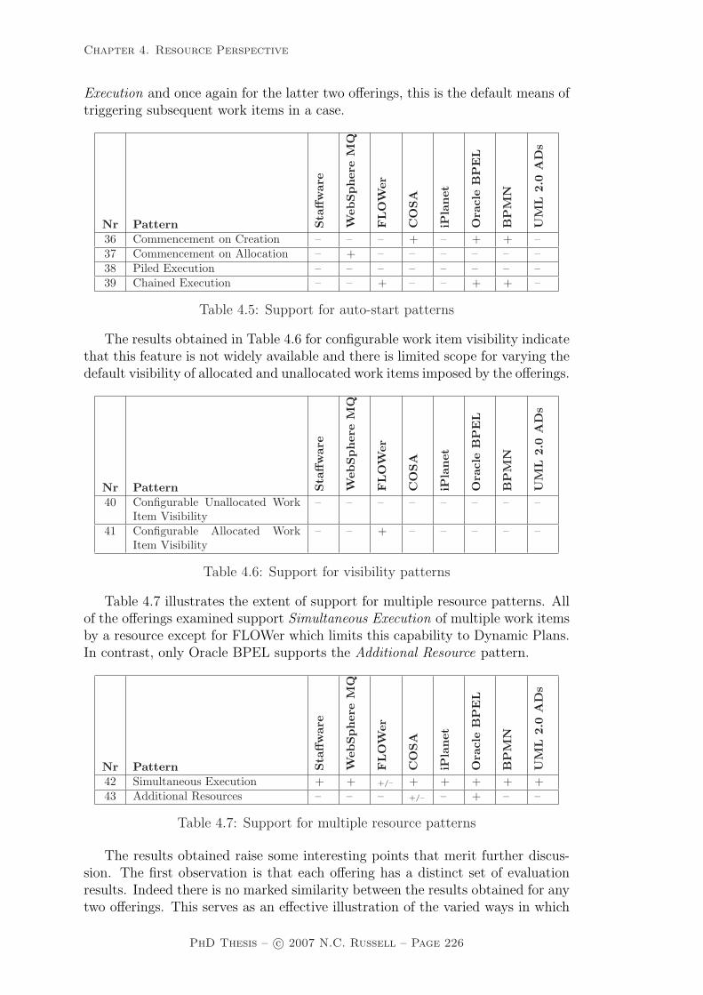
Chapter 4. Resource Perspective
Execution and once again for the latter two offerings, this is the default means oftriggering subsequent work items in a case.
Nr Pattern Sta
ffw
are
Web
Spher
eM
Q
FLO
Wer
CO
SA
iPla
net
Ora
cle
BP
EL
BP
MN
UM
L2.
0A
Ds
36 Commencement on Creation – – – + – + + –37 Commencement on Allocation – + – – – – – –38 Piled Execution – – – – – – – –39 Chained Execution – – + – – + + –
Table 4.5: Support for auto-start patterns
The results obtained in Table 4.6 for configurable work item visibility indicatethat this feature is not widely available and there is limited scope for varying thedefault visibility of allocated and unallocated work items imposed by the offerings.
Nr Pattern Sta
ffw
are
Web
Spher
eM
Q
FLO
Wer
CO
SA
iPla
net
Ora
cle
BP
EL
BP
MN
UM
L2.
0A
Ds
40 Configurable Unallocated WorkItem Visibility
– – – – – – – –
41 Configurable Allocated WorkItem Visibility
– – + – – – – –
Table 4.6: Support for visibility patterns
Table 4.7 illustrates the extent of support for multiple resource patterns. Allof the offerings examined support Simultaneous Execution of multiple work itemsby a resource except for FLOWer which limits this capability to Dynamic Plans.In contrast, only Oracle BPEL supports the Additional Resource pattern.
Nr Pattern Sta
ffw
are
Web
Spher
eM
Q
FLO
Wer
CO
SA
iPla
net
Ora
cle
BP
EL
BP
MN
UM
L2.
0A
Ds
42 Simultaneous Execution + + +/– + + + + +43 Additional Resources – – – +/– – + – –
Table 4.7: Support for multiple resource patterns
The results obtained raise some interesting points that merit further discus-sion. The first observation is that each offering has a distinct set of evaluationresults. Indeed there is no marked similarity between the results obtained for anytwo offerings. This serves as an effective illustration of the varied ways in which
PhD Thesis – c© 2007 N.C. Russell – Page 226

Chapter 4. Resource Perspective
the resource perspective is implemented across the range of PAIS and businessprocess modelling languages examined and reinforces the need for a fundamentaltaxonomy of the various concepts relevant to the resource perspective. It is thisneed that the patterns identified in this chapter hope to address.
A consideration that stems from these variations is that although several of theofferings examined are classified as workflow systems, their individual capabilitiesdiffer significantly. This raises the issue of suitability and the need to determinewhich sets of patterns an offering should support in order to fulfil a specificoperational need. For example, which set of patterns is required for schedulingand managing production in a factory as against tracking claims in an insurancecompany. Through better understanding of the conceptual requirements of aparticular problem domain in terms of the patterns identified above, it should beeasier to select the required technology support.
Another interesting observation is that Staffware, the workflow system whichsupports least patterns, is the one which has the greatest market share. Thisfurther reinforces the notion of suitability – presumably Staffware is widely usedbecause it has features which are directly relevant to a broad range of problem do-mains – but it also suggests that the BPM marketplace is relatively immature andthat the conceptual requirements of specific problem domains and the technologysupport that might be appropriate to them need to be better understood.
Indeed even recently developed offerings such as BPEL provide minimal con-sideration of the resource perspective as evidenced its absence of pattern support.It is interesting to note that as a remedy to this shortcoming the BPEL4Peopleextension [KKL+05] has recently been proposed for BPEL in order to more ad-equately address the needs of users. Consequently individual vendors offeringBPEL implementations are dealing with this shortcoming in their own way andthe breadth of pattern support demonstrated by Oracle BPEL indicates thatconsiderable work has gone into addressing this issue.
The timing of work item enablement with respect to distribution is an areathat merits further investigation. All of the systems examined support the notionof enablement on distribution but there was minimal support for early or latedistribution. Both of these alternatives offer opportunities for improving overallprocess throughput. In the case of early distribution, the onus for scheduling thebest use of available work time can be placed on individual resources who canbe presented with a pipeline of upcoming work items that they need to plan tocomplete in the most effective way. Late distribution provides the system withthe ability to actively match the amount of work in the system with availableresources. This ensures that resources are not overwhelmed with the relentlessaddition of new work items and removes the potential for “thrashing” whereresources spend more time organizing and switching between concurrent workitems than actually working on them.
Another interesting shortcoming of several of the systems examined is their in-ability to prioritize the way in which work items are offered to multiple resources.In most cases, the work item is simply presented to all identified resources si-multaneously. Other than for COSA, there is no integrated ability to select apreferred resource on a round robin, shortest queue or even random basis.
PhD Thesis – c© 2007 N.C. Russell – Page 227

Chapter 4. Resource Perspective
Another area for potential improvement is illustrated by the lack of supportfor auto-start patterns. These patterns aim to increase overall work throughputby automatically starting the next work item for a resource and by pipelining likework items thus minimizing familiarization and switching time for resources.
One final observation relates to the amount of autonomy granted to resourcesby the system. Case handling systems such as FLOWer provide significant lati-tude to resources by allowing them to organize the sequence in which they willundertake the work items in a given case. One of the drawbacks of the case han-dling approach is that the act of allocating all of the work items in a case to asingle resource potentially removes the opportunities that may exist for execut-ing work items in parallel and allocating them to several distinct resources. In aworkflow system context, work items in a given case can be allocated to multipleresources and there is the option for executing work items in parallel. Anotheropportunity for improving process throughput is by providing resources with theability to redistribute work items where the routing decisions made by the systemare not aligned with current resource workloads. The results obtained for detourpatterns indicate that whilst existing offerings already offer some support, thereis further opportunity in this area.
4.11 Related work
Despite the central role that resources play in PAIS, there is a surprisinglysmall body of research into resource and organizational modelling in this con-text [Aal03, AKV03]. In early work, Bussler and Jablonski [BJ95] identified anumber of shortcomings of workflow systems when modelling organizational andpolicy issues. In subsequent work [JB96], they presented one of the first broadattempts to model the various perspectives of workflow systems in an integratedmanner including detailed consideration of the organizational view.
One line of research into resource modelling and enactment in a workflow con-text has focussed on the characterization of resource managers which can manageorganizational resources and enforce resource policies. Du and Shan [DS99] pre-sented the design of a resource manager for a workflow system. It includes ahigh level resource model together with proposals for resource definition, queryand policy languages. Similarly Lerner et al. [LNOP00] presented an abstractresource model in the context of a workflow system although their focus is moreon the efficient management of resources in a workflow context than the specificways in which work is allocated to them. Huang and Shan [HS99] presented aproposal for handling resource policies in a workflow context. Three types of pol-icy – qualification, requirement and substitution – were described together witha means for efficiently implementing them when allocating resources to activities.
Another area of investigation has been into ensuring that only suitable and au-thorized users are selected to execute a given work item. The RBAC (Role-BasedAccess Control) model [FSG+01] presents an approach for doing this. Whilsteffective, RBAC models focus on security considerations and neglect other orga-nizational aspects such as resource availability.
PhD Thesis – c© 2007 N.C. Russell – Page 228

Chapter 4. Resource Perspective
Several researchers have developed meta-models, i.e., object models describ-ing the relation between workflow concepts, which include work allocation aspects[AK01, Mue99a, Mue04, RM98]. However, these meta-models tend to focus onthe structural description of resource properties and typically do not describe thedynamics aspects of work distribution. One of the most successful attempts inthis area has been the work of Pesic and van der Aalst [PA05] which lays thefoundation for a comprehensive reference model for work distribution by describ-ing a number of the resource patterns presented in this chapter in the form ofColoured Petri nets.
4.12 Summary
This chapter has identified 43 Resource Patterns which describe the manner inwhich work items are distributed and executed by resources in PAIS. These pat-terns have been validated through a detailed review of eight contemporary of-ferings. This evaluation revealed that whilst most offerings cater for simple ap-proaches to work distribution, there are a range of possible opportunities for in-creasing the precision and effectiveness of work directives in PAIS. Moreover, therange of patterns supported by individual tools and standards varies markedly.This gives rise to the question of suitability, i.e. which sets of patterns are neces-sary in order to make an offering useful for a specific purpose. It is anticipatedthat the detailed descriptions provided for each of the Resource Patterns willenable this issue to be more thoroughly investigated.
PhD Thesis – c© 2007 N.C. Russell – Page 229

Chapter 5. Exception Handling Perspective
Chapter 5
Exception Handling Perspective
Process-aware information systems are generally based on a comprehensive pro-cess model (often depicted in graphical form) that maps out all of the possibleexecution paths associated with a business process. This ensures that the workactivities which comprise each of the likely execution scenarios are fully described.Whilst this approach to specifying business process works well for well-behavedcases of a process, i.e. those that conform to one of the expected execution paths,it is less successful in dealing with undesirable events that may be encounteredduring execution.
Deviations from normal execution arising during a business process are oftentermed exceptions in line with the notion of exceptions which is widely used inthe software engineering community [Goo75, Cri82, Bor85]. Because it is difficultto individually cater for all of the undesirable situations that may arise duringthe execution of a program, the notion of exceptions was developed where theseevents or conditions are grouped into classes which are related both in termsof the characteristics that they exhibit and the circumstances under which theymight arise. Exception handlers can then be defined in the form of programmaticprocedures to deal with specific issues where they are detected. Depending on theseverity of the problem, it may be possible to resolve it and continue execution,take some form of alternative action or, in the worst case, terminate execution.
Initially proposed as a software development methodology, the inherent ben-efits delivered by this approach to handling unanticipated software issues hasseen them increasingly become an integrated feature of many contemporary lan-guages [RS03, GRRX01]. Not surprisingly, the range approaches supported fordetecting exceptions, selecting suitable handlers and managing their resolutionhas also become increasingly sophisticated [BRM00] and the applicability of theseapproaches to related domains such as information systems has also been recog-nized [RS03] although in domains such as these, exceptions are usually definedat a higher level of abstraction and are identified by violations to assertions orintegrity constraints rather than lower level events (such as divide by zero errors)as is the case in programming languages. Nevertheless, the approaches taken toidentifying suitable handling strategies and actually dealing with detected excep-tions tend to be generally applicable across domains regardless of the conceptuallevel of the exception being addressed.
PhD Thesis – c© 2007 N.C. Russell – Page 230

Chapter 5. Exception Handling Perspective
As with the preceding chapters that seek to provide a conceptual foundationfor the control-flow, data and resource perspectives of PAIS, this chapter focuseson doing the same for the exception handling perspective. However, it adopts adistinct approach to that taken in previous chapters. The control-flow, data andresource perspectives are orthogonal to each other and there is minimal interrela-tionship between them. The exception handling perspective differs in this regardas it is based on all of these perspectives and it is responsible for dealing withundesirable events which may arise in each of them. Consequently the approachto describing the conceptual basis of the exception handling perspective is a littledifferent.
First, this chapter investigates the range of issues that may lead to exceptionsduring process execution and the various ways in which they can be addressed.This provides the basis for a classification framework for exception handling thatis subsequently defined in the form of patterns. The motivation for this researchis to provide a conceptual framework for classifying the exception handling capa-bilities of PAIS in a manner that is independent of specific modelling approachesor technologies. This approach is distinguished from other research activitiesin this area which seek to extend specific process modelling formalisms and en-actment technologies to provide support for expected and unexpected events byincorporating exception detection and handling capabilities. Instead of directlyproposing a concrete implementation, this chapter proceeds as follows: first themajor factors associated with exception handling are delineated and investigatedin detail. On the basis of these findings, a patterns-based classification frame-work is proposed for describing the exception handling capabilities of PAIS. Thisis then used to assess the exception handling capabilities of a variety of contem-porary PAIS and business process modelling languages. Finally on the basis ofthe insights gained from these activities, a generic graphical exception handlinglanguage is proposed.
5.1 A framework for exception handling
This section considers the notion of an exception in a general sense and thevarious ways in which they can be triggered and handled. The assumption isthat an exception is a distinct, identifiable event which occurs at a specific pointin time during the execution of a process and relates to a unique work item34.The occurrence of the exception is assumed to be immediately detectable as isthe type of the exception. The manner in which the exception is handled willdepend on the type of exception that has been detected. There are a range ofpossible ways in which an exception may be dealt with but in general, the specifichandling strategy centres on three main considerations:
• How the work item will be handled;
• How the other work items in the case will be handled; and
34Exceptions may also be bound to groups of tasks, blocks or even entire cases, and in thesesituations it is assumed that the same handling considerations apply to all of the encompassedtasks.
PhD Thesis – c© 2007 N.C. Russell – Page 231
Chapter 5. Exception Handling Perspective
• What recovery action will be taken to resolve the effects of the exception.
The range of possible exception types and the options for handling them arediscussed in the following sections.
5.1.1 Exception types
It is only possible to specify handlers for expected types of exception. Withthis constraint in mind, a comprehensive literature review and a broad survey ofcurrent commercial PAIS and business process modelling and execution languageswas undertaken in order to determine the range of exception events that arecapable of being detected and provide a useful basis for recovery handling. Theseevents can be classified into five distinct groups.
Work item failure
Work item failure during the execution of a process is generally characterized bythe inability of the work item to progress any further. This may manifest itselfin a number of possible forms including a user-initiated abort of the executingprogram which implements the work item, the failure of a hardware, softwareor network component associated with the work item or the user to whom thework item is assigned signalling failure to the enabling PAIS. Where the reasonfor this failure is not captured and dealt within the process model, it needs to behandled elsewhere in order to ensure that both later work items and the processas a whole continue to behave correctly.
Deadline expiry
It is common to specify a deadline for a work item in a process model. Usually thedeadline indicates when the work item should be completed, although deadlinesfor commencement are also possible. In general with a deadline, it is also useful tospecify at design time what should be done if the deadline is reached at runtimeand the work item has not been completed.
Resource unavailability
It is often the case that a work item requires access to one or more data resourcesduring its execution. If these are not available to the work item at initiation,then it is usually not possible for the work item to proceed. Similarly, PAIS arepremised on the fact that work items are usually allocated to resources (typicallyhuman) who execute them. Problems with work item allocation can arise if (1) atdistribution time, no resource can be found which meets the specified distributioncriteria for the work item or (2) at some time after allocation, the resource is nolonger able to undertake or complete the work item. Although the occurrence ofthese issues can be automatically detected, they often cannot be resolved withinthe context of the executing process and may involve some form of escalation ormanual intervention. For this reason, they are ideally suited to resolution viaexception handling.
External trigger
Triggers from sources external to a work item are often used as a means of sig-nalling the occurrence of an event that impacts on the work item and requires
PhD Thesis – c© 2007 N.C. Russell – Page 232

Chapter 5. Exception Handling Perspective
some form of handling. These triggers are typically initiated by non-linked workitems (i.e. work items that are not directly linked to the work item in questionby a control edge) elsewhere within the process model or even in other processmodels or alternatively from processes in the operational environment in whichthe PAIS resides. Although a work item can anticipate events such as triggersand provision for dealing with them can be included at design time, it is notpredictable if or when such events will occur. For this reason, the issue of dealingwith them is often not suited to normal processing within the work item imple-mentation and is better dealt with via exception handling. Generally signals orsome other form of processing interrupt indicate that an out-of-bound conditionhas arisen and needs to be dealt with. A general consequence of this is thatthe current work item needs to be halted, possibly undone and some alternativeaction taken.
Constraint violation
Constraints in the context of a PAIS are invariants over elements in the control-flow, data or resource perspectives that need to be maintained to ensure theintegrity and operational consistency of the process is preserved. Ongoing moni-toring is generally required to ensure that they are enforced. The implementationof routines to identify and handle constraint violations detected within the con-text of a process is similar to the issue of dealing with external triggers. Typicallythe construct that will detect and need to deal with the violation is a work itemalthough there is no reason why the constraint could not be specified and handledat block or process level. As constraints may be specified over data, resources orother work items within a process model, the approach chosen for handling themneeds to be as generic as possible to ensure that it has broadest applicability.
5.1.2 Exception handling at work item level
In general an exception will relate to a specific work item in a case. There area multitude of ways in which the exception can be handled although the specificdetails will depend on the current state of execution of the work item. Beforelooking at these options, it is worthwhile reviewing the execution lifecycle for awork item. Figure 5.1 illustrates the lifecycle of a work item from the perspectiveof an individual resource. It is based on the general lifecycle for a work itemdiscussed in section 4.2 on which the Resource Patterns are based. Figure 5.1depicts as solid arrows the states through which a work item progresses duringnormal execution. It is initially offered to one or more resources for execution.A resource issues an allocate request to indicate that it wishes to execute thework item at some future time, the work item then is allocated to that resource.Typically this involves adding the work item to the resource’s work queue andremoving any references to the work item that other resources may have received,either on their work queues or via other means. When the resource wishes tocommence the work item, it issues a start request and the state of the workitem changes to started. Finally, once the work item is finished, the resourceissues a complete request and the state of the work item is changed to completed.Note that there are two possible variations to this course of events shown asdotted arcs in Figure 5.1: (1) where a work item offered to a resource is selected
PhD Thesis – c© 2007 N.C. Russell – Page 233

Chapter 5. Exception Handling Perspective
by another resource, it is withdrawn from the first resource’s worklist and (2)where an executing work item is detected as having failed, its state is changedaccordingly. These correspond to termination actions in relation to the work itemthat are outside the control of the resource.
handling
started
failed
complete
fail
force−complete
force−fail
restart
allocated startallocate
reoffer
continue−offer continue−allocation continue−execution
reoffer−a
reoffer−s
reallocate−s
offered
force−fail−a
force−fail−o
withdrawn
completed
force−complete−o
reallocate
withdraw
force−complete−a
normal
state transitions:
termination
exception
Figure 5.1: Options for handling work items
Of most interest are the dashed lines that exist between states in Figure 5.1.These provide the basis for determining what options exist for handling a workitem in a given state when an exception is detected. There are fifteen of theseexception state transitions. As there are subtle differences between each of thesetransitions, and in order to distinguish between them, each of them is brieflydescribed below:
1. continue-offer (OCO) – the work item has been offered to one or moreresources and there is no change in its state as a consequence of the excep-tion;
2. reoffer (ORO) – the work item has been offered to one or more resourcesand as a consequence of the exception, these offers are withdrawn and thework item is once again offered to one or more resources (these resourcesmay not necessarily be the same as those to which it was offered previously);
3. force-fail-o (OFF) – the work item has been offered to one or more re-sources, these offers are withdrawn and the state of the work item is changedto failed. No subsequent work items on this path are triggered;
4. force-complete-o (OFC) – the work item has been offered to one ormore resources, these offers are withdrawn and the state of the work itemis changed to completed. All subsequent work items are triggered;
5. continue-allocation (ACA) – the work item has been allocated to aspecific resource that will execute it at some future time and there is nochange in its state as a consequence of the exception;
6. reallocate (ARA) – the work item has been allocated to a resource, thisallocation is withdrawn and the work item is allocated to a different re-source;
PhD Thesis – c© 2007 N.C. Russell – Page 234

Chapter 5. Exception Handling Perspective
7. reoffer-a (ARO) – the work item has been allocated to a resource, thisallocation is withdrawn and the work item is offered to one or more re-sources (this group may not necessarily include the resource to which itwas previously allocated);
8. force-fail-a (AFF) – the work item has been allocated to a resource, thisallocation is withdrawn and the state of the work item is changed to failed.No subsequent work items are triggered;
9. force-complete-a (AFC) – the work item has been allocated to a resource,this allocation is withdrawn and the state of the work item is changed tocompleted. All subsequent work items are triggered;
10. continue-execution (SCE) – the work item has been started and thereis no change in its state as a consequence of the exception;
11. restart (SRS) – the work item has been started, progress on the cur-rent execution instance is halted and the work item is restarted from thebeginning by the same resource that was executing it previously;
12. reallocate-s (SRA) – the work item has been started, progress on thecurrent execution instance is halted and the work item is reallocated to adifferent resource for later execution;
13. reoffer-s (SRO) – the work item has been started, progress on the currentexecution instance is halted and it is offered to one or more resources (thisgroup may not necessarily include the resource that was executing it);
14. force-fail (SFF) – the work item is being executed, any further progresson it is halted and its state is changed to failed. No subsequent work itemsare triggered; and
15. force-complete (SFC) – the work item is being executed, and furtherprogress on it is halted and its state is changed to completed. All subsequentwork items are triggered.
5.1.3 Exception handling at case level
Exceptions always occur in the context of one or more cases that are in the processof being executed. In addition to dealing with the specific work item to whichthe exception relates, there is also the issue of how the case should be dealt within an overall sense, particularly in regard to other work items that may currentlybe executing or will run at some future time. There are three alternatives forhandling cases:
1. continue with case (CWC) – the case can be continued, with no inter-vention occurring in the execution of any other work items;
2. remove current case (RCC) – selected or all remaining work items inthe case can be removed (including those currently executing); or
PhD Thesis – c© 2007 N.C. Russell – Page 235

Chapter 5. Exception Handling Perspective
3. remove all cases (RAC) – selected or all remaining work items in boththis and all other currently executing cases which correspond to the sameprocess model can be removed.
In the latter two scenarios, a selection of work items to be removed can bespecified using both static design time information relating to the correspondingtask definition (e.g. original role allocation) as well as relevant runtime informa-tion (e.g. actual resource allocated to, start time).
5.1.4 Recovery action
The final consideration in regard to exception handling is what action will betaken to remedy the effects of the situation that has been detected. There arethree alternate courses of action:
1. no action (NIL) – do nothing;
2. rollback (RBK) – rollback the effects of the exception, by reversing thepreceding process execution events recorded in the execution log; or
3. compensate (COM) – compensate for the effects of the exception.
Rollback and compensation are analogous to their usual definitions (e.g. asdescribed in [MRKS92]). When specifying a rollback action, the point in theprocess (i.e. the task) to which the process should be undone can also be stated.By default this is just the current work item, although it can be any precedingpoint in the process. When a rollback action is initiated, the execution stateof the process instance is reversed back to the point identified for the rollbackby undoing the effects of any work items that have executed subsequent to therollback point. It is important to note that this does not necessarily result inthe execution state after rollback being identical to the execution state whenthe rollback point occurred originally during execution of the process instance,it merely undoes the effects of any subsequent work items as recorded in theexecution log. The effectiveness of this recovery strategy is largely governed bythe richness of the events captured in the execution log and some events (e.g.resource allocation, production of hard-copy reports) cannot be undone.
For compensation actions, a corresponding compensation process must alsobe identified. As with rollback, this process aims to undo the effects of precedingwork items that resulted in or were affected by the exception. Because an entireprocess can be associated with the recovery action, it provides a more flexiblemeans of remedying the effects of the exception and allows a wide variety of issuesto be addressed, not just the observable actions as recorded in the execution log.
5.1.5 Characterizing exception handling strategies
The actual recovery response to any given class of exception can be specifiedas a pattern which succinctly describes the form of recovery that will be at-tempted. Specific exception patterns may apply in multiple situations in a given
PhD Thesis – c© 2007 N.C. Russell – Page 236

Chapter 5. Exception Handling Perspective
process model (i.e. for several distinct constructs), possibly for different types ofexception. Exception patterns take the form of tuples comprising the followingelements:
• How the task on which the exception is based should be handled;
• How the case and other related cases in the process in which the exceptionis raised should be handled; and
• What recovery action (if any) is to be undertaken.
Each of these patterns describes a specific exception handling approach thatmay be associated with a process. Moreover these patterns generalize to a vari-ety of distinct offerings and abstract from the actual manner in which they areimplemented. Hence they meet with the definition of a pattern adopted duringthis research as an “abstraction from concrete form which keeps recurring in spe-cific, non-arbitrary contexts” [RZ96]. However they operate at a different levelof abstraction the the control-flow, data and resource patterns described in thepreceding chapters and are not comparable with them. As such, the exceptionhandling patterns should be viewed as a taxonomy of exception handling strate-gies for PAIS rather than as a set of conceptual characteristics associated withexception handling. To better understand the information captured by individualexception patterns, it is worthwhile considering some examples.
The pattern SFF-CWC-COM specified for a work item failure exception forthe Advise Head Office task in the Fortnightly Payroll process indicates that if afailure of a work item corresponding to the Advise Head Office task is detectedwhen it has been started, then the work item should be terminated, have its statechanged to failed and the nominated compensation task should be invoked. Noaction should be taken with other work items in the same case. It is importantto note that this pattern only applies to instances of the work item that fail oncestarted, it does not apply to instances in the offered or allocated states (which ifrequired should have distinct patterns nominated for them).
The pattern OFF-RCC-NIL specified for a work item deadline exception forthe Confirm Transport task in the Base Restock process indicates that if thedeadline is reached for a work item corresponding to the Confirm Transport taskthat is in the offered state, then the state of the work item should be changed tofailed and all other work items in the current case should be withdrawn. No otherrecovery action should be undertaken. In essence, the pattern indicates that thefailure to secure transport by the required deadline for the process instance issufficiently serious that the process instance should be halted. In this scenario,it is likely the the additional patterns AFF-RCC-NIL and SFF-RCC-NIL wouldalso be specified for the work item deadline for the Confirm Transport task, sothat regardless of the state of the work item, failure to meet its specified deadlineresults in the process instance being halted.
The pattern AFC-CWC-NIL specified for a resource unavailability exceptionfor the Tidy Locker Room task in the Prepare for Match process indicates thatshould a work item corresponding to the Tidy Locker Room task be allocated toa resource and that resource become unavailable before the work item is com-menced, then the work item should be marked as complete (thus triggering any
PhD Thesis – c© 2007 N.C. Russell – Page 237

Chapter 5. Exception Handling Perspective
subsequent work items), other work items in the case should be continued andno other recovery action should be undertaken. In effect, this exception handlingstrategy indicates the Tidy Locker Room task can be skipped if the resource towhich it is allocated becomes unavailable.
From the various options identified for each of pattern elements in Sections5.1.2 – 5.1.4, there are 135 possible patterns that can be conceived. However, notall patterns apply to a given exception type, and Table 5.1 identifies those whichapply to each of the exception types identified in Section 5.1.1.
Work ItemFailure
Work ItemDeadline
ResourceUnavailable
ExternalTrigger
ConstraintViolation
OFF-CWC-NIL OCO-CWC-NIL ORO-CWC-NIL OCO-CWC-NIL SCE-CWC-NILOFF-CWC-COM ORO-CWC-NIL OFF-CWC-NIL OFF-CWC-NIL SRS-CWC-NILOFC-CWC-NIL OFF-CWC-NIL OFF-RCC-NIL OFF-RCC-NIL SRS-CWC-COMOFC-CWC-COM OFF-RCC-NIL OFC-CWC-NIL OFC-CWC-NIL SRS-CWC-RBKAFF-CWC-NIL OFC-CWC-NIL ARO-CWC-NIL ACA-CWC-NIL SFF-CWC-NILAFF-CWC-COM ACA-CWC-NIL ARA-CWC-NIL AFF-CWC-NIL SFF-CWC-COMAFC-CWC-NIL ARA-CWC-NIL AFF-CWC-NIL AFF-RCC-NIL SFF-CWC-RBKAFC-CWC-COM ARO-CWC-NIL AFF-RCC-NIL AFC-CWC-NIL SFF-RCC-NILSRS-CWC-NIL AFF-CWC-NIL AFC-CWC-NIL SCE-CWC-NIL SFF-RCC-COMSRS-CWC-COM AFF-RCC-NIL SRA-CWC-NIL SRS-CWC-NIL SFF-RCC-RBKSRS-CWC-RBK AFC-CWC-NIL SRA-CWC-COM SRS-CWC-COM SFF-RAC-NILSFF-CWC-NIL SCE-CWC-NIL SRA-CWC-RBK SRS-CWC-RBK SFC-CWC-NILSFF-CWC-COM SCE-CWC-COM SRO-CWC-NIL SFF-CWC-NIL SFC-CWC-COMSFF-CWC-RBK SRS-CWC-NIL SRO-CWC-COM SFF-CWC-COMSFF-RCC-NIL SRS-CWC-COM SRO-CWC-RBK SFF-CWC-RBKSFF-RCC-COM SRS-CWC-RBK SFF-CWC-NIL SFF-RCC-NILSFF-RCC-RBK SRA-CWC-NIL SFF-CWC-COM SFF-RCC-COMSFC-CWC-NIL SRA-CWC-COM SFF-CWC-RBK SFF-RCC-RBKSFC-CWC-COM SRA-CWC-RBK SFF-RCC-NIL SFF-RAC-NILSFC-CWC-RBK SRO-CWC-NIL SFF-RCC-COM SFC-CWC-NIL
SRO-CWC-COM SFF-RCC-RBK SFC-CWC-COMSRO-CWC-RBK SFF-RAC-NILSFF-CWC-NIL SFC-CWC-NILSFF-CWC-COM SFC-CWC-COMSFF-CWC-RBKSFF-RCC-NILSFF-RCC-COMSFF-RCC-RBKSFC-CWC-NILSFC-CWC-COM
Table 5.1: Exceptions patterns support by exception type
5.2 Survey of exception handling capabilities
The exception patterns identified in Section 5.1 were used to assess the exceptionhandling capabilities of eight PAIS and business process modelling languages. Theresults35 of this survey are captured in Table 5.2. They provide a salient insightinto how little of the research into exception handling has been implemented incommercial offerings.
Only deadline expiry enjoys widespread support although its overall flexibil-ity is limited in many tools. Only two of the offerings examined provide supportfor handling work items failures – generally via user-initiated aborts. There is
35Combinations of patterns are written as regular expressions, e.g. (SFF|SFC)-CWC-COMrepresents the two patterns SFF-CWC-COM and SFC-CWC-COM.
PhD Thesis – c© 2007 N.C. Russell – Page 238

Chapter 5. Exception Handling Perspective
OfferingExceptions
Work ItemFailure
Work ItemDeadline
ExternalTrigger
ConstraintViolation
StaffwareProcessSuite v9
OCO-CWC-COM
OCO-CWC-NIL
ACA-CWC-COM
ACA-CWC-NIL
OFF-CWC-COM SCE-CWC-NILAFF-CWC-COM SCE-CWC-COMSCE-CWC-COM
WebSphere MQ3.4 (IBM)
OCO-CWC-NILACA-CWC-NILSCE-CWC-NIL
FLOWer 3.1(Pallas Athena)
AFC-CWC-NIL AFC-CWC-NILSFC-CWC-NIL SFC-CWC-NIL
AFC-CWC-COMSFC-CWC-COM
COSA 5.1(Transflow)
SFF-CWC-RBK OCO-CWC-COM
OCO-CWC-COM
ACA-CWC-COM
ACA-CWC-COM
SCE-CWC-COM SCE-CWC-COMiPlanet Integ.Server 3.1 (Sun)
(OFF|OFC|AFF|AFC|SRS|SFC|SFF)-(CWC|RCC)-(NIL|COM)
XPDL 2.0(WfMC)
SFF-CWC-COM SCE-CWC-COM SFF-CWC-COM SFF-CWC-COMSFF-CWC-NIL SCE-CWC-NIL SFF-CWC-NIL SFF-CWC-NILSFF-RCC-COM SFF-CWC-COM SFF-RCC-COM SFF-RCC-COMSFF-RCC-NIL SFF-CWC-NIL SFF-RCC-NIL SFF-RCC-NIL
SFF-RCC-COMSFF-RCC-NIL
BPEL 1.1
SFF-CWC-COM SCE-CWC-COM SCE-CWC-COMSFF-CWC-NIL SCE-CWC-NIL SCE-CWC-NILSFF-RCC-COM SFF-CWC-COM SFF-CWC-COMSFF-RCC-NIL SFF-CWC-NIL SFF-CWC-NIL
SFF-RCC-COM SFF-RCC-COMSFF-RCC-NIL SFF-RCC-NIL
BPMN 1.0(OMG)
SFF-CWC-COM SFF-CWC-COM SFF-CWC-COM SFF-CWC-COMSFF-CWC-NIL SFF-CWC-NIL SFF-CWC-NIL SFF-CWC-NILSFC-CWC-COM SFC-CWC-COM SFC-CWC-COM SFC-CWC-COMSFC-CWC-NIL SFC-CWC-NIL SFC-CWC-NIL SFC-CWC-NILSRS-CWC-COM SRS-CWC-COM SRS-CWC-COM SRS-CWC-COMSRS-CWC-NIL SRS-CWC-NIL SRS-CWC-NIL SRS-CWC-NILSFF-RCC-COM SFF-RCC-COM SFF-RCC-COM SFF-RCC-COMSFF-RCC-NIL SFF-RCC-NIL SFF-RCC-NIL SFF-RCC-NIL
Table 5.2: Support for exception patterns
also minimal support for external triggers and constraint violation managementamongst the workflow tools with only Staffware and COSA, and FLOWer re-spectively supporting these exception classes. The business process languages(XPDL, BPEL and BPMN) provide better support across most areas althoughonly for active work items. None of the offerings examined provided exceptionsupport for managing resource unavailability (and as a consequence this columnhas been omitted from Table 5.2) – this reflects the research findings in Chapter4 and elsewhere [RAHE05] on the lack of support for the resource perspective incurrent commercial products.
PhD Thesis – c© 2007 N.C. Russell – Page 239

Chapter 5. Exception Handling Perspective
5.3 Considerations for a process exception lan-
guage
The insights gained in the previous sections in relation to the identification andhandling of exceptions provide the basis for a general exception handling lan-guage for processes. This section proposes a set of primitives for addressingexceptions that might arise during process execution and presents a mechanismfor integrating these primitives with the process model more generally. It thendemonstrates the applicability of this approach to exception handling through aworking example.
The conceptual model presented in Section 5.1 identified three key dimensionsto handling an exception. These dimensions provide the basis for the primitivesin the exception language illustrated in Figure 5.2. Symbols 1–4, 8 and 12–14 are derived from the actions for dealing with the current work item fromFigure 5.1, symbols 5–7 and 9–11 are derived from the options for dealing withother work items currently active in the same and other cases and symbols 15and 16 correspond to the two forms of recovery action that can be undertaken.These primitives can be assembled into sequences of actions that define exceptionhandling strategies. These sequences can also contain standard YAWL constructsalthough this capability is not illustrated here.
C
or thread
2. Suspend current work item
1. Remove current work item
3. Continue current work item
R16. Rollback task
15. Compensation task
14. Reoffer current work item
13. Reallocate current work item
4. Restart current work item 12. Force fail current work item8. Force complete current work item
items in current case
5. Remove selected/all work
6. Suspend selected/all work
7. Continue selected/all work
9. Remove selected/all work
10. Suspend selected/all work
items in current case items in all cases
items in all cases
items in all cases11. Continue selected/all work
items in current case
Figure 5.2: Exception handling primitives
The interlinkage of exception handling strategies based on these primitivesand the overall process model is illustrated in Figure 5.3. A clear distinction isdrawn between the process model and the exception handling strategies. This isbased on the premise that the process model should depict the normal sequenceof activities associated with a business process and should aim to present theseactivities precisely without becoming overburdened by excessive consideration ofundesirable events that might arise during execution.
PhD Thesis – c© 2007 N.C. Russell – Page 240

Chapter 5. Exception Handling Perspective
Exception handling strategies are able to be bound to one of five distinctprocess constructs: individual tasks, a scope (i.e. a group of tasks), a block, aprocess (i.e. all of the tasks in a process model) and a process environment (i.e.all of the process models in a given environment). The binding is specific toone particular type of exception, e.g. work item failure or constraint violation.It may also be further specialized using conditions based on elements from thedata perspective, e.g. there may be two exception handling strategies for a task,one for work items concerned with financial limits below $1000, the other withlimits above that figure. Exception handling strategies defined for more specificconstructs take precedence to those defined at a higher level, e.g. where a task hasa work item failure exception strategy defined and there is also a strategy definedat the process-level for the same exception type, then the task-level definition isutilized should it experience such an exception. The primitives provide flexibilityfor a describing wide range of exception handling strategies, although the actualcontents of a specific strategy will generally be determined by the type of excep-tion that it is associated with. Table 5.1 gives an indication of the approachesthat are meaningful for each exception type.
process definition
take order
check credit organize shipping
pick order
produce invoice
despatch order
update account
complete order
print picking slip
C
exception handling definition
constraint violation
deadline expiry
work item failure
<deadline>
<constraint>
Figure 5.3: Exception handling strategies for a process
In order to illustrate the application of these concepts, an example is presentedbased on the order fulfillment process illustrated in Figure 5.4 using the YAWLprocess modelling notation. In this process, orders are taken from customers,and a picking slip for the required items is prepared and subsequently used toselect them from the warehouse. At the same time, the customer’s credit ischecked and shipping is organized for the order. When all of these tasks arecomplete an invoice is prepared for the customer and the goods are then packedand despatched whilst the customers account is updated with the outstandingamount. The order details are then finalized and filed.
Figure 5.5(a) illustrates two alternate exception handling strategies for thecheck credit work item. The first of these is used when the amount of creditrequired is less than $100. It involves suspending the work item, advancing tothe next work item and starting it. In summary, the credit check work item isskipped and control is returned to the process at the commencement of the next
PhD Thesis – c© 2007 N.C. Russell – Page 241

Chapter 5. Exception Handling Perspective
print picking slip
take order
check credit organize shipping
pick order
produce invoice
despatch order
update account
complete order
Figure 5.4: Order despatch process
work item. For situations where the credit required is $100 or more, the currentwork item is suspended, the execution point is rewound to the beginning of thework item and it is recommenced.
Figure 5.5(b) shows the exception handling strategy for the pick order workitem where the deadline for its completion is exceeded. In general, the aim is todespatch orders within 48 hours of them being received. Where this deadline isnot met, recovery involves suspending the current work item, reassigning it toanother resource, running a compensation task that determines if the order canbe despatched to the customer within 48 hours (and if not applying a small creditto the account), then the pick order work item is restarted with the new resource.
credit required >= $100
a. Work item failure − check credit task b. Deadline expiry − pick order task
d. Trigger received − order despatch process
e. Constraint violation − take order task
c. Resource unavailable − order despatch process.
account_frozen trigger
credit required < $100
data resource unavailable
human resource unavailable
constraint:order value < customer credit limit − current account balance
C
R
Figure 5.5: Exception handling strategies – order despatch process
Figure 5.5(c) illustrates the resource unavailable handling strategy. Wherethe required resource is a data resource, this involves stopping the current workitem, going back to its beginning and restarting it. This strategy is bound to theprocess model, i.e. by default, it applies to all work items. In the event where theunavailable resource is a human resource (i.e. the person undertaking the workitem), the recovery action is also shown in Figure 5.5(c) and involves suspendingthe work item, reassigning it to another person and then restarting it from thebeginning.
Figure 5.5(d) indicates the exception handling strategy when an account frozentrigger is received by any of the tasks in the current process. In this situation,the recovery action is to stop the current work item and all other work items inthe process and to undertake a rollback action which involves undoing all changes
PhD Thesis – c© 2007 N.C. Russell – Page 242

Chapter 5. Exception Handling Perspective
which have occurred right the way back to the beginning of the case. In otherwords, any work that has been undertaken on despatching goods to the customeris completely undone.
Finally, Figure 5.5(e) illustrates the recovery action that is taken when theorder value constraint is exceeded for the take order task. In this case thestrategy is simply to stop the work item and all other work items (if any) in theprocess.
5.4 Related work
The need for reliable, resilient and consistent business process operation has longbeen recognized [GHS95]. In the main, the focus of research in this area has beendirected towards workflow systems which until recently have served as the mainenactment vehicle for PAIS. Early work in the area [Elm92, WS97] was essentiallya logical continuation of database transaction theory and focussed on developingextensions to the classic ACID transaction model that would be applicable in ap-plication areas requiring the use of long duration and more flexible transactions.As the field of workflow technology matured, the applicability of exceptions tothis problem of ensuring execution integrity was also recognized [SW95, SM95]and Eber and Liebhart [EL96] presented the first significant discussion on work-flow recovery which incorporated exceptions. A key aspect of this work was theclassification of exceptions into four types: basic failures, application failures,expected exceptions and unexpected exceptions. Subsequent research efforts intoworkflow exceptions have mainly concentrated on the last two of these classes andon this basis, the field has essentially bifurcated into two research areas. Inves-tigations into expected exceptions have focussed previous work on transactionalworkflow into mechanisms for introducing exception handling frameworks intoworkflow systems. Research into unexpected exceptions has established the areasof adaptive workflow and workflow evolution [RRD04].
Although it is not possible to comprehensively survey these research areas, itis worthwhile identifying some of the major contributions that have influencedsubsequent research efforts and have a bearing on this research initiative. Sig-nificant attempts to include advanced transactional concepts and exception han-dling capabilities in workflow systems include WAMO [EL95] which provided theability to specify transactional properties for tasks which identified how failuresshould be dealt with, ConTracts [RS95a] which proposed a coordinated, nestedtransaction model for workflow execution allowing for forward, backward andpartial recovery in the event of failure and Exotica [AAA+96] which provided amechanism for incorporating Sagas and Flexible transactions in the commercialFlowMark workflow product. OPERA [HA98, HA00] was one of the first initia-tives to incorporate language primitives for exception handling into a workflowsystem and it also allowed exception handling strategies to be modelled in thesame notation as that used for representing workflow processes. TREX [SMA+98]proposed a transaction model that involves treating all types of workflow failuresas exceptions. A series of exception types were delineated and the exception han-dler utilized in a given situation was determined by a combination of the taskand the exception experienced. WIDE [CCPP99] developed a comprehensive lan-
PhD Thesis – c© 2007 N.C. Russell – Page 243

Chapter 5. Exception Handling Perspective
guage – Chimera-Exc – for specifying exception handling strategies in the formof Event-Condition-Action (ECA) rules.
Other important contributions include Leymann and Roller’s [LR97] whichidentified the concepts of compensation spheres (collections of activities in a pro-cess that must all execute successfully or be subject to compensation actions)and atomicity spheres (collections of activities that must all commit or abort)and their applicability to workflow systems, Derks et al.’s work [DDGJ01] whichproposed independent models for the specification of workflow and transactionproperties using generic rules to integrate the workflow specification and theatomicity specification into a single model based on Petri Nets, Borgida and Mu-rata’s paper [BM99] which proposed modelling workflow systems as a set of reifiedobjects with associated constraints and conceptualizing exceptions as violationsof those constraints which are capable of being detected and managed, Bram-billa et al.’s paper [BCCT05] which describes a high-level framework for handlingexceptions in web-based workflow applications together with an implementationbased on extensions to WebML and Mehrotra et al.’s work [MRKS92] which firstidentified the pivot, retriable and compensation transaction concepts widely usedin subsequent research.
Identifying potential exceptions and suitable handling strategies is a signifi-cant problem for large, complex workflows and recent attempts [GCDS01, HT04]to address this have centred on mining previous execution history to gain anunderstanding of past exception occurrences and using this knowledge (eitherat design or runtime) in order to determine a suitable handling strategy. Kleinand Dellarocas [KD00] proposed a knowledge-based solution to the issue basedon the establishment of a shared, generic and reusable taxonomy of exceptions.Luo et al. [LSKM00] used a case-based reasoning approach to match exceptionoccurrences with suitable handling strategies.
Until recently the area of unexpected exceptions has mainly been investigatedin the context of adaptive or evolutionary workflow [RRD04] which centre ondynamic change of the process model. [WRR07] offers an insight into the rangeof possible changes that a PAIS may need to adapt to and characterizes these inthe form of change patterns. A detailed review of this area is beyond the scope ofthis chapter, however two recent initiatives which offer the potential to addressboth expected and unexpected exceptions simultaneously are ADOME-WFMS[CLK01] which provides an adaptive workflow execution model in which excep-tion handlers are specified generically using ECA rules providing the opportunityfor reuse in multiple scenarios and user-guided adaptation where they are notfound to be suitable, and Adams et al.’s approach [AHEA05] which describes acombination of “worklets” and “ripple-down rules” as a means of dynamic work-flow evolution and exception handling.
5.5 Summary
This chapter has presented a classification framework for exception handling inPAIS based on patterns. This framework is independent of specific modellingapproaches or technologies and as such provides an objective means of delineating
PhD Thesis – c© 2007 N.C. Russell – Page 244

Chapter 5. Exception Handling Perspective
the exception-handling capabilities of specific PAIS. It is subsequently used toassess the level of exceptions support provided by eight commercial PAIS andbusiness process modelling languages. On the basis of these investigations, agraphical, tool-independent language is proposed for defining exception handlingstrategies in PAIS.
This chapter concludes Part One of the thesis which has provided a concep-tual foundation for PAIS through the identification of fundamental characteristicsrelevant to the modelling and enactment of business processes. In addition to theclassification framework and generic graphical language for the exception han-dling perspective described above, 126 patterns have also been identified whichcharacterize core constructs in the control-flow, data and resource perspectives.Precise descriptions have been presented for each of these patterns along withexamples of their use, motivation for their utilization, an overview of their oper-ation, details of their implementation, context conditions that govern their use,potential issues and solutions associated with their use and evaluation criteriathat describe necessary conditions that PAIS must meet in order to be consid-ered to support them. Each of the patterns have been validated through a surveyof their support in a wide range of contemporary PAIS and business process mod-elling languages. Consequently, this part of thesis has addressed the first of theresearch activities identified in Section 1.4.1, namely it has identified the corecomponents of a business process.
In Part Two of the thesis, these findings are taken and used as the basis for thedefinition of a reference language for PAIS. This language embodies the broadestpossible range of patterns relevant to the control-flow, data and resource perspec-tives. It is formally defined and an abstract syntax and operational semantics areprovided for it.
PhD Thesis – c© 2007 N.C. Russell – Page 245

Chapter 5. Exception Handling Perspective
PhD Thesis – c© 2007 N.C. Russell – Page 246

Part II
Language Design
247

This page is intentionally blank
248
Part One of the thesis presented a comprehensive conceptual foundation forPAIS in the form of patterns catalogues identifying the core constructs in thecontrol-flow, data and resource perspectives of business processes. It also pre-sented a patterns-based classification framework for describing exception han-dling capabilities of PAIS and on the basis of this proposed a generic graphicallanguage for modelling exception handling strategies.
In this part of the thesis, newYAWL, a reference language for PAIS is pro-posed. This language is founded on the range of patterns identified in Part Onefor the control-flow, data and resource perspectives together with the graphicalexception handling language. It encompasses the broadest range of these pat-terns that is consistent with business process modelling and enablement. As thepatterns characterize solutions to modelling and enactment issues that occur inpractice, newYAWL is well suited to the comprehensive modelling of businessprocesses both at a conceptual and operational level. Moreover it supports thecapture of sufficient detail about a business process to enable it to be directlyenacted.
This part of the thesis is organized as follows: Chapter 6 introduces thenewYAWL language and the range of language elements that it encompasses.Chapter 7 presents an abstract syntax for newYAWL that precisely describes thestatic content of a newYAWL business process model. It also presents a seriesof transformations that enable a design-time newYAWL model to be mapped toan executable runtime model. Chapter 8 provides an operational semantics fornewYAWL defining how each language element is enacted at runtime. Chapter9 presents the results of a pattern-based assessment of newYAWL allowing itscapabilities to be compared with other PAIS. Chapter 10 concludes the thesis.
PhD Thesis – c© 2007 N.C. Russell – Page 249

Chapter 6. An Introduction to newYAWL
Chapter 6
An Introduction to newYAWL
newYAWL is a reference language for PAIS. It represents a synthesis of the con-temporary range of control-flow, data and resource patterns together with thegraphical exception handling language presented in the first part of this the-sis. This chapter provides an introduction to each of the main constructs in thecontrol-flow, data, resource and exception handling perspectives of newYAWL.
6.1 Control-flow perspective
Figure 6.1 identifies the complete set of language elements which comprise thecontrol-flow perspective of newYAWL. All of the language elements in YAWLhave been retained36 and perform the same functions. There is a brief recap ofthe operation of each of these constructs below. A more detailed discussion ofYAWL can be found elsewhere [AH05]. A multitude of new constructs have alsobeen added to address the full range of patterns identified in Part One of thisthesis. Each of these constructs is subsequently discussed in more detail.
6.1.1 Existing YAWL constructs
newYAWL inherits all of the existing constructs from YAWL together with itsrepresentation of a process model. As in YAWL, a newYAWL specification iscomposed of a set of newYAWL-nets in the form of a rooted graph structure.Each newYAWL-net is composed of a series of tasks and conditions. Tasks andconditions in newYAWL nets play a similar role to transitions and places inPetri nets. Atomic tasks have a corresponding implementation that underpinsthem. Composite tasks refer to a unique newYAWL-net at a lower level in thehierarchy which describes the way in which the composite task is implemented.One newYAWL-net, referred to as the top level process or top level net, does nothave a composite task referring to it and it forms the root of the graph.
Each newYAWL-net has one unique input and output condition. The inputand output conditions of the top level net serve to signify the start and endpoint
36The visual format of the cancellation region is slightly different although its operation isunchanged.
PhD Thesis – c© 2007 N.C. Russell – Page 250

Chapter 6. An Introduction to newYAWL
NEW CONSTRUCTS
Persistent trigger task
Transient trigger task
Completion region
Blocking region
EXISTING CONSTRUCTS
Disablement arc
#
#
Composite task
Multiple instances ofan atomic task
Multiple instances ofa composite task
Atomic taskCondition
Input condition
Output condition
AND−join task
XOR−join task
OR−join task
AND−split task
XOR−split task
OR−split task
Thread split task
Thread merge task
Partial−join task
Repetitive task (while/repeat)
Cancellation region
Figure 6.1: newYAWL symbology
for a process instance. Similar to Petri nets, conditions and tasks are connected inthe form of a directed graph, however there is one distinction in that newYAWLallows for tasks to be directly connected to each other. In this situation, it isassumed that an implicit condition exists between them from a semantic per-spective.
It is possible for tasks (both atomic and composite) to be specified as havingmultiple instances (as indicated in Figure 6.1). Multiple instance tasks (abbrevi-ated hereafter as MI tasks) can have both lower and upper bounds on the numberof instances created after initiating the task. It is also possible to specify thatthe task completes once a certain threshold of instances have completed. If nothreshold is specified, the task completes once all instances have completed. If athreshold is specified, the behaviour of the task depends on whether the task isidentified as being cancelling or non-cancelling. If it is cancelling, all remaininginstances are terminated when the threshold is reached and the task completes.If it is non-cancelling, the task completes when the threshold is reached, but anyremaining instances continue to execute until they complete normally. Howevertheir completion is inconsequential and does not result in any other side-effects.Should the task commence with the required number of minimum instances andall of these complete but the required threshold of instance completions is notreached, the multiple instance task is deemed complete once there are no furtherinstances being executed (either from the original set of instances when the task
PhD Thesis – c© 2007 N.C. Russell – Page 251

Chapter 6. An Introduction to newYAWL
was triggered or additional instances that were started subsequently). Finally,it is possible to specify whether the number of task instances is fixed after cre-ating the initial instances (i.e. the task is static) or whether further instancescan be added while there are still other instances being processed (i.e. the taskis dynamic). Through various combinations of these settings, it is possible toimplement all of the MI patterns that have been identified.
Tasks in a newYAWL-net can have specific join and split behaviours associ-ated with them. The traditional join and split constructs (i.e. AND-join, OR-join, XOR-join, AND-split, OR-split and XOR-split) are included in newYAWLtogether with three new constructs: thread split, thread merge and partial joinwhich are discussed in detail in Sections 6.1.2 and 6.1.3. The operation of eachof the joins and splits in newYAWL is as follows:
• AND-join – the branch following the AND-join receives the thread of controlwhen all of the incoming branches to the AND-join in a given case have beenenabled.
• OR-join – the branch following the OR-join receives the thread of controlwhen either (1) each active incoming branch has been enabled in a givencase or (2) it is not possible that any branch that has not yet been enabledin a given case will be enabled at any future time.
• XOR-join – the branch following the XOR-join receives the thread of controlwhen one of the incoming branches to the XOR-join in a given case has beenenabled.
• AND-split – when the incoming branch to the AND-split is enabled, thethread of control is passed to all of the branches following the AND-split.
• OR-split – when the incoming branch to the OR-split is enabled, the threadof control is passed to one or more of the branches following the OR-split,based on the evaluation of conditions associated with each of the outgoingbranches.
• XOR-split – when the incoming branch to the XOR-split is enabled, thethread of control is passed to precisely one of the branches following theXOR-split, based on the evaluation of conditions associated with each ofthe outgoing branches.
Finally, newYAWL also inherits the notion of a cancellation region fromYAWL. A cancellation region encompasses a group of conditions and tasks ina newYAWL-net. It is linked to a specific task in the same newYAWL-net. Atruntime, when an instance of the task to which the cancellation region is con-nected completes executing, all of the tasks in the associated cancellation regionthat are currently executing for the same case are withdrawn. Similarly any to-kens that reside in conditions in the cancellation region that correspond to thesame case are also withdrawn.
This concludes the discussion of constructs in newYAWL that are inheritedfrom YAWL. We now introduce new constructs for the control-flow perspective.
PhD Thesis – c© 2007 N.C. Russell – Page 252

Chapter 6. An Introduction to newYAWL
6.1.2 Thread split and merge
The thread split and thread merge constructs provide ways of initiating and co-alescing multiple independent threads of control within a given process instancethus providing an alternate mechanism to the multiple instance activity for in-troducing concurrency into a process.
The thread split is a split construct which initiates a specified number ofoutgoing threads along the outgoing branch when a task completes. It is identifiedby a # symbol on the righthand side of the task. Only one outgoing branch canemanate from a thread split and all initiated execution threads flow along thisbranch. The number of required threads is identified in the design-time processmodel.
The thread merge is a join construct which coalesces multiple independentthreads of control prior to the commencement of an activity. Similar to thethread merge, it is denoted by a # symbol however in this case it appears on thelefthand side of the activity. A thread merge can only have a single incomingbranch.
Figure 6.2 provides an illustration of the use of these constructs in the contextof a car inspection process. A car inspection consists of four distinct activitiesexecuted sequentially. First the lights are inspected, then the tyres, then theregistration documents before finally a record is made of the inspection results.It is expected that a car has five tyres hence five distinct instances of the inspecttyre activity are initiated. Only when all five of these have completed does thefollowing activity commence.
results
# #
inspecttyre
inspectregistration
inspectlights
documentinspection
Figure 6.2: Example of thread split and merge usage
6.1.3 Partial join
The partial join (or the n-out-of-m join) is a variant of the AND-join which fireswhen input has been received on n of the incoming branches (i.e. it fires earlierthan would ordinarily be the case with an AND-join which would wait for inputto be received on all m incoming branches). The construct resets (and can bere-enabled) when input has been received on all (m) of the incoming branches. Ablocking region can be associated with the join, in which tasks are blocked (i.e.they cannot be enabled or, if already enabled, cannot proceed any further in theirexecution) after the join has fired until the time that it resets.
Figure 6.3 illustrates the use of the partial join in the context of a morecomprehensive vehicle inspection process. After the initiate inspection activityhas completed, the mechanical inspection, records inspection and licence checkactivities run concurrently. If all of them complete without finding a problem,then no action is taken and the file report activity concludes the process instance.
PhD Thesis – c© 2007 N.C. Russell – Page 253

Chapter 6. An Introduction to newYAWL
However if any of the inspection activities finds a problem, the defect noticeactivity is initiated and once complete any remaining inspection activities arecancelled, followed by a full inspection activity before the final file report. Inthis example, the partial join corresponds to a 1-out-of-3 join without a blockingregion.
initiate
noticefull
inspection
filereportinspection
mechanicalinspection
recordsinspection
licencecheck
noaction
defect
Figure 6.3: Example of the partial join: defect notice is a 1-out-of-3 join
6.1.4 Task repetition
Task repetition is essentially an augmentation of the task construct which haspre-test and/or post-test conditions associated with it. If the pre-test conditionis not satisfied, the task is skipped. If the post-test condition is not satisfied,the task repeats. These conditions allows while, repeat and combination loops tobe constructed for individual tasks. Where a specific condition is not associatedwith a pre-test or post-test, they are assumed to correspond to true resulting inthe task being executed or completed respectively
Figure 6.4 illustrates the implementation of a repeat loop for a given taskin the context of a renew drivers licence process. An instance of the process isstarted for each person applying to renew their existing licence. Depending onthe results of the eyesight test activity, a decision is made as to whether to issuea person with a new licence. For those people that pass the test, they have theirphoto taken and if they are not satisfied with the result, have it taken againuntil they are (i.e. take photo is executed one or more times). The licence is thenissued. Finally the paperwork is filed for all applicants who apply for a licence.
paperworktake
photoissue
licenceeyesight
testfile
Figure 6.4: Example of a repeat loop
PhD Thesis – c© 2007 N.C. Russell – Page 254

Chapter 6. An Introduction to newYAWL
Another example of the use of this construct is illustrated in Figure 6.5. Thisshows how a while loop is implemented in the context of a composite task. Themotor safety campaign process essentially involves a running a series of vehicleinspections at a given motor vehicle dealer to ensure that the vehicles for saleare roadworthy. It is a simple process, first the vehicles to be inspected arechosen. Then the list of vehicles is passed to the conduct inspections task. Thisis composite in form and repeatedly executes the associated subprocess whilethere are vehicles remaining on the list to inspect.
report
action
defectnotice
fullinspection
file
selectvehicles
conductinspections
mechanicalinspection
recordsinspection
initiateinspection
licencecheck
no
Figure 6.5: Example of a while loop
There is also support for combination loops in newYAWL. This construct isillustrated by the conduct inspection task in Figure 6.6. It has both a pre-test anda post-test condition associated with it. These are evaluated at the beginning andend of each task instance respectively and are distinct conditions. In this example,the pre-test condition is that there are vehicles to inspect. If this condition is truethen an instance of the conduct inspection task is commenced otherwise the taskis skipped. The post-test condition has two parts: (1) there are no more vehiclesremaining to inspect or (2) there is not enough time for another inspection. If thiscondition is false then an instance of the conduct inspection task is commenced(providing the pre-test evaluates to true) otherwise the thread of control is passedto the following task.
6.1.5 Persistent and transient triggers
One of the major deficits of YAWL was the inability for processes to be influencedby or respond to stimuli from the external environment unless parts of the processor the entire process was subcontracted to an external service. The inclusion of
PhD Thesis – c© 2007 N.C. Russell – Page 255

Chapter 6. An Introduction to newYAWL
fileinspections
conductinspection
schedulepaperwork
Figure 6.6: Example of a combination loop
triggers provides a means for the initiation of work items to be directly controlledfrom outside of the context of the process instance. Two distinct types of triggersare recognized in newYAWL: persistent triggers and transient triggers. Thesedistinguish between the situations where the triggers are durable in form andremain pending for a task in a given process instance until consumed by thecorresponding work item and those where the triggers are discarded if they donot immediately cause the initiation of the associated work item. In both cases,triggers have a unique name and must be directed at a specific task instance(i.e. a work item) in a specific process instance. To assist in identifying thisinformation so that triggers can be correlated with the relevant work item, theprocess environment may provide facilities for querying the identities of currentlyactive process and task instances.
Figure 6.7 illustrates the operation of a persistent trigger in the context ofa registration plate production process. Once initiated, the process instance re-ceives triggers from an external system advising that another registration plateis required. It passes these on to the produce plates task. As this is a mechani-cal process which involves the use of a specific machine and bulk materials, it ismore efficient to produce the plates in batches rather than individually. For thisreason, the produce plates activity waits until 12 requests have been received andthen executes, cancelling any further instances of the receive registration requesttask once it has completed. The trigger associated with the receive registrationrequest task is persistent in form as it is important that individual registrationrequests are not lost. A transient trigger does not retain pending triggers (i.e.triggers must be acted on straightaway or they are irrevocably lost) hence it isunsuitable for use in this situation.
#
receiveregistration
request
produceplates
Figure 6.7: Example of persistent trigger usage
Figure 6.8 illustrates the operation of a transient trigger in the context of arefinery plant initiation process. The request startup task commences the firingup of the various plant and equipment associated with an oil refinery, howeverthis task can only proceed when both the refinery plant initiation process hasbeen initiated and a safety check completed trigger has been received. The safetycheck completed is an output from an internal safety check run by the plant
PhD Thesis – c© 2007 N.C. Russell – Page 256

Chapter 6. An Introduction to newYAWL
machinery every 90 seconds. The trigger is transient in form and if not consumedimmediately, it is discarded and the user must wait until the next trigger isreceived before the request startup task can commence.
startuprequest refinerystartup
Figure 6.8: Example of transient trigger usage
6.1.6 Completion region
Cancellation regions have been retained from YAWL and a new construct – thecompletion region – has been introduced which operates in an analogous wayto the cancellation region, except that when the task to which the region islinked completes, all of the tasks within the region are force-completed. Thismeans that if they are enabled or executing, they are disabled and the task(s)subsequent to them are triggered. All such tasks are noted as being “completed”(this may involve inserting appropriate log entries in the execution log). Wherethe task is composite in form, it is marked as having completed and its associatedsubprocess(es) has all active tasks within it disabled and any pending tokensremoved.
There are two scenarios associated with the completion region that deservespecial mention. The first of these is where a multiple instance is included withinthe completion region. In this situation, any incomplete instances are automat-ically advanced to a completed state. Where data elements are passed from themultiple instance task to subsequent tasks (e.g. as part of the aggregator query)there may be the potential for the inclusion of incomplete data (i.e. multipleinstance data elements will be aggregated from all task instances, regardless ofwhether they have been defined or not).
The second situation involves data passing from tasks that have not yet com-pleted. If these tasks pass data elements to subsequent tasks, there is the potentialfor ambiguity in the situation where a “force completion” occurs. In particular,the use of mandatory output data parameters or postconditions (see Section 6.2.4for more details on the operation of postconditions) that assume the existence offinal data values may cause the associated work item to hang. In order to resolvethis problem, any tasks within a completion region should not have mandatoryoutput data parameters or postconditions specified for them that assume the ex-istence of final data values or care should be taken to ensure that appropriatevalues are set at task initiation.
Figure 6.9 provides an example of the operation of the cancellation region inthe context of the collate monthly statistics process for the motor vehicle reg-istry. At the end of each month the preceding month’s activities are reviewed togather statistics suitable for publication in the department’s marketing brochure.Because this is a time-consuming activity, it is time-bounded to ensure timely
PhD Thesis – c© 2007 N.C. Russell – Page 257

Chapter 6. An Introduction to newYAWL
publication of the statistics. This generally means that only a subset of the pre-vious month’s records are actually examined. After the review is initiated, thisis achieved by setting a timeout. In parallel with this, multiple instances of thereview records task are initiated (one for each motor vehicle record processed inthe last month). The review records task is in a completion region which is trig-gered by the timeout activity being completed. This stops any further recordsprocessing and allows the publish statistics task to complete on a timely basis.Should the review records task complete ahead of schedule, then the timeout iscancelled.
statisticsreview
timeout
publish
reviewrecords
initiate
Figure 6.9: Example of completion region usage: timeout forces review records tocomplete
A variant of this process is illustrated in Figure 6.10. Unlike the previousmodel, it uses an external trigger to signal when the review process should com-plete. This trigger is transient in form as any triggers received before the reviewrecords task has commenced must be ignored. This variant is less efficient as thepublish statistics task can only commence when the publish decision trigger hasbeen received (i.e. there is no provision for the review records task to completeearly).
decision
publishstatistics
publish
reviewrecords
initiatereview
Figure 6.10: Example of completion region usage using transient triggers
PhD Thesis – c© 2007 N.C. Russell – Page 258

Chapter 6. An Introduction to newYAWL
6.1.7 Dynamic multiple instance task disablement
The disablement link provides a means of stopping a dynamic multiple instancetask from having any further instances created. It is triggered when another taskin the same process completes. The example in Figure 6.11 illustrates part ofthe paper review process for a conference. After a call for papers has been made,multiple instances of the accept submission activity can execute. One is triggeredfor each paper submission that is received. A manual activity exists for imposingthe submission deadline. This is triggered by an external transient trigger. Oncereceived, it disables the accept submission activity preventing any further papersfrom being accepted. However, all of the processing for already accepted paperscompletes normally and once done, the organize reviews activity is initiated.
deadline
organize
acceptsubmission
call forpapers reviews
impose
Figure 6.11: Example of dynamic multiple instance task disablement
6.2 Data perspective
The data perspective of newYAWL encompasses the definition of a range of dataelements, each with a distinct scoping. These data elements are used for managingdata with a newYAWL process instance and are passed between process compo-nents using formal parameters. In order to integrate the data and control-flowperspectives, support is provided in newYAWL for specifying logical conditionsbased on data elements that define whether the thread of control can be passedto a given branch in a process (link condition) and also whether a specific pro-cess component can start or complete execution (pre or postcondition). Finally,there is also support for managing consistency of data elements in concurrentenvironments using locks. All of these newYAWL data constructs are discussedsubsequently.
6.2.1 Data element support
newYAWL incorporates a wide range of facilities for data representation andhandling. Variables of eight distinct scopings are recognized as follows:
PhD Thesis – c© 2007 N.C. Russell – Page 259

Chapter 6. An Introduction to newYAWL
• External variables are defined in the operational environment in which anewYAWL process executes (but are external to it). They can be accessedthroughout all instances of all newYAWL process models;
• Folder variables are defined in the context of a (named) folder. A foldercan be accessed by one or more process instances at runtime. They donot necessarily need to relate to the same process model. Individual pro-cess instances can specify the folders they require at the time they initiateexecution;
• Global variables are bound to a specific newYAWL specification and areaccessible throughout all newYAWL-nets associated with it at runtime;
• Case variables are bound to an instance of a specific newYAWL specifi-cation. At runtime a new instance of the case variable is created for ev-ery instance of the newYAWL specification that is initiated. This variableinstance is accessible throughout all newYAWL-nets associated with thenewYAWL process instance at runtime;
• Block variables are bound to a specific instance of a newYAWL-net. Atruntime a new instance of the block variable is created for every instanceof the newYAWL-net that is initiated. This variable instance is accessiblethroughout the newYAWL-nets at runtime;
• Scope variables are bound to a specific scope within a process instance of anewYAWL-net. At runtime a new instance of the scope variable is createdfor every instance of the newYAWL-net instance that is initiated. Thisvariable instance is accessible only to the task instances belonging to thescope at runtime;
• Task variables are bound to a specific task. At runtime a new instance ofthe task variable is created for every instance of the task that is initiated.This variable instance is accessible only to the corresponding task instanceat runtime; and
• Multiple-Instance variables are bound to a specific instance of a multiple-instance task. At runtime a new instance of the multiple instance variableis created for every instance of the multiple instance task that is initiated.This variable instance is accessible only to this instance of the task instanceat runtime.
6.2.2 Data interaction support
There are a series of facilities for transferring data elements between internal andexternal locations. Data passing between process constructs (e.g. block to task,composite task to subprocess decomposition, block to multiple instance task) isspecified using formal parameters and utilizes a function-based approach to datatransfer, thus providing the ability to support inline formatting of data elementsand setting of default values. Parameters can be associated with tasks, blocksand processes. They take the following form:
PhD Thesis – c© 2007 N.C. Russell – Page 260

Chapter 6. An Introduction to newYAWL
parameter input-vars mapping-function output-vars direction participation
where direction specifies whether the parameter is an input or output parameterand participation indicates whether it is mandatory or optional. Input param-eters are responsible for passing data elements into the construct to which theparameter is bound and output parameters are responsible for passing data el-ements out. Mandatory parameters require the evaluation of the parameter toyield a defined result (i.e. not an undefined value) in order to proceed. Depend-ing on whether the parameter is an input or output parameter, an undefinedresult for the parameter evaluation would prevent the associated construct fromcommencing or completing.
The action of evaluating the parameter for singular tasks, blocks and pro-cesses occurs in two steps: (1) the specified mapping function is invoked withthe values of the nominated input variables then (2) the result is copied to thenominated output variable. For all constructs other than multiple instance tasks,the resultant value can only be copied to one output variable in one instance ofthe construct to which they are bound. For multiple instance parameters, thesituation is a little more complicated as the parameter is responsible for inter-acting with multiple variables in multiple task instances. The situation for inputmultiple instance parameters is illustrated in Figure 6.12. When a multiple in-stance parameter is evaluated, it yields a tabular result (indicated by var saltab).The number of rows indicate how many instances of the multiple instance taskare to be started. The list of output variables for the parameter correspond tovariables that will be created in each task instance. Each row in the tabular resultis allocated to a distinct task instance and each column in the row correspondsto the value allocated to a distinct variable in the task instance.
Jones A07
Brown TEMP $23
$62
CEOSmith $140
work items:
parameter:
var saltab:
WI: A.1
name: Smithposition: CEOrate: $140
WI: A.3
name: Brownposition: TEMPrate: $23
WI: A.2
name: Jonesposition: A07rate: $62
function
task
type
in vars
out vars nameposition
rate
misplit()
saltab
invar
A
A
Figure 6.12: Multiple instance input parameter handling
For output multiple instance parameters, the situation is reversed as illus-trated in Figure 6.13 and the values of the input variables listed for the parameterare coalesced from multiple task instances into a single tabular result that is thenassigned to the output variable.
PhD Thesis – c© 2007 N.C. Russell – Page 261
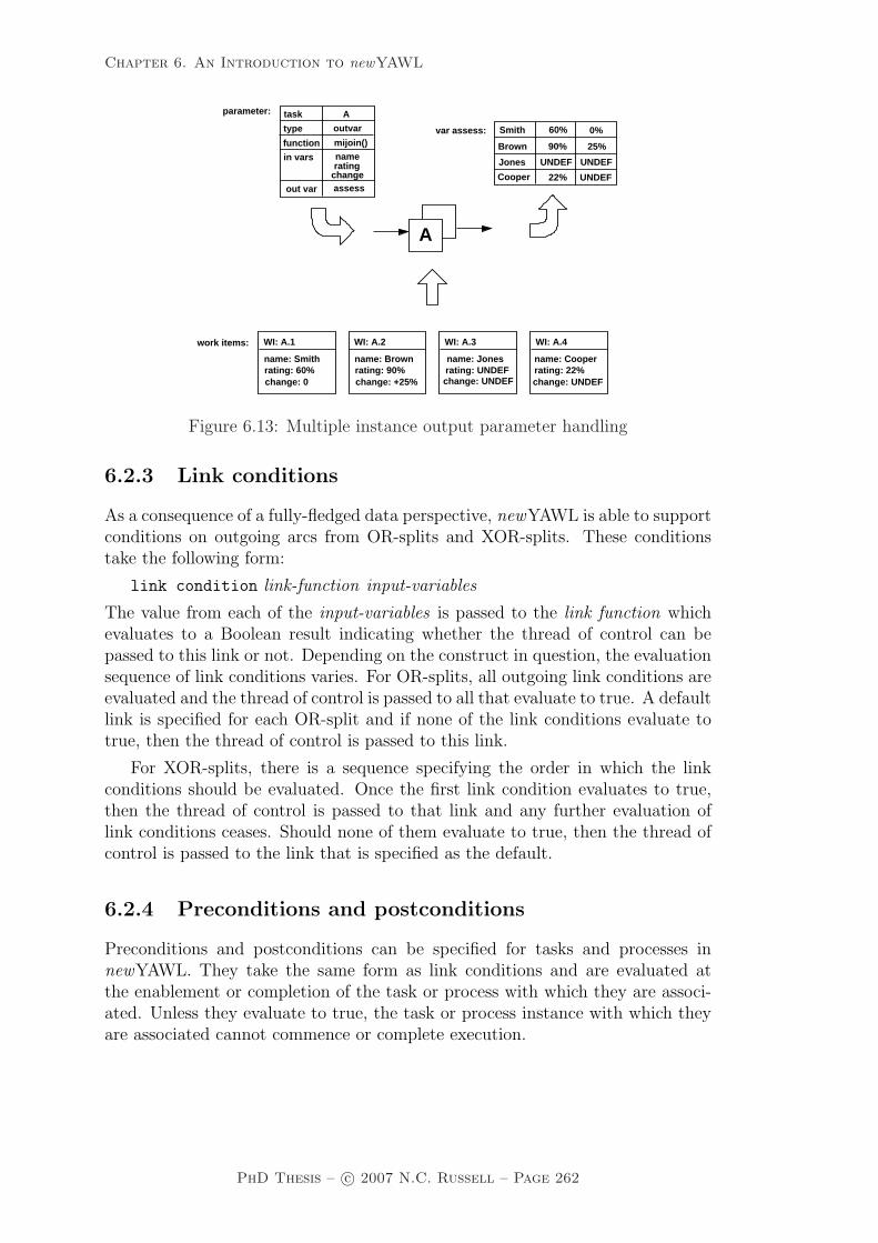
Chapter 6. An Introduction to newYAWL
function
task
type
in vars
mijoin()
A
outvar
namerating
changeout var assess
var assess:
25%
0%60%
WI: A.1
name: Smithrating: 60%change: 0
WI: A.2
name: Brownrating: 90%change: +25%
parameter:
work items: WI: A.3
rating: UNDEFchange: UNDEF
name: Jones
WI: A.4
change: UNDEFrating: 22%name: Cooper
Jones
Smith
Brown
Cooper
UNDEF
UNDEF
UNDEF
22%
90%
A
Figure 6.13: Multiple instance output parameter handling
6.2.3 Link conditions
As a consequence of a fully-fledged data perspective, newYAWL is able to supportconditions on outgoing arcs from OR-splits and XOR-splits. These conditionstake the following form:
link condition link-function input-variables
The value from each of the input-variables is passed to the link function whichevaluates to a Boolean result indicating whether the thread of control can bepassed to this link or not. Depending on the construct in question, the evaluationsequence of link conditions varies. For OR-splits, all outgoing link conditions areevaluated and the thread of control is passed to all that evaluate to true. A defaultlink is specified for each OR-split and if none of the link conditions evaluate totrue, then the thread of control is passed to this link.
For XOR-splits, there is a sequence specifying the order in which the linkconditions should be evaluated. Once the first link condition evaluates to true,then the thread of control is passed to that link and any further evaluation oflink conditions ceases. Should none of them evaluate to true, then the thread ofcontrol is passed to the link that is specified as the default.
6.2.4 Preconditions and postconditions
Preconditions and postconditions can be specified for tasks and processes innewYAWL. They take the same form as link conditions and are evaluated atthe enablement or completion of the task or process with which they are associ-ated. Unless they evaluate to true, the task or process instance with which theyare associated cannot commence or complete execution.
PhD Thesis – c© 2007 N.C. Russell – Page 262

Chapter 6. An Introduction to newYAWL
6.2.5 Locks
newYAWL allows tasks to specify data elements that they require exclusive accessto (within a given process instance) in order to commence. Once these dataelements are available, the associated task instance retains a lock on them untilit has completed execution preventing any other task instances from using themconcurrently. This lock is relinquished once the task instance completes.
6.3 Resource perspective
newYAWL provides support for a broad range of work distribution facilities,inspired by the Resource Patterns presented in Part One of the thesis, that havenot been previously embodied in other PAIS. Traditional approaches to workitem routing based on itemization of specific users and roles are augmented witha sophisticated array of new features. There are a variety of differing ways inwhich work items may be distributed to users. Typically these requirements arespecified on a task-by-task basis and have two main components:
1. The interaction strategy by which the work item will be communicated tothe user, their commitment to executing it will be established and the timeof its commencement will be determined; and
2. The routing strategy which determines the range of potential users that canundertake the work item.
newYAWL also provides additional routing constraints that operate with agiven case to restrict the users a given work item is distributed to based onthe routing decisions associated with previous work items in the case. There isalso the ability to specify privileges for each user in order to define the rangeof operations that they can perform when undertaking work items and there arealso two advanced operating modes that can be utilized in order to expedite workthroughput for a given user. Each of these features is discussed in detail below.
6.3.1 Work item interaction strategies
The potential range of interaction strategies that can be specified for tasks innewYAWL are listed in Table 6.1. They are based on the specification at threemain interaction points – offer, allocation and start – of the identity of the partythat will be responsible for determining when the interaction will occur. Thiscan be a resource (i.e. an actual user) or the system. Depending on the combina-tion of parties specified for each interaction, a range of possible distributions arepossible as detailed below. From the perspective of the resource, each interactionstrategy results in a distinct experience in terms of the way in which the workitem is distributed to them. The range of strategies supported range from highlyregimented schemes (e.g. SSS) where the work item is directly allocated to theresource and started for them and the resource has no involvement in the distri-bution process through to approaches that empower the resource with significant
PhD Thesis – c© 2007 N.C. Russell – Page 263

Chapter 6. An Introduction to newYAWL
autonomy (e.g. RRR) where the act of committing to undertake a work item anddeciding when to start it are completely at the resource’s discretion.
As an aid to understanding the distinctions between the various interactionsdescribed in Table 6.1, it is possible to illustrate them quite effectively usingUML Sequence Diagrams as depicted in Figure 6.14. These show the range ofinteractions between the system and resources that can occur when distributingwork items. The work distribution, worklist handler and management interven-tion objects corresponds to the system, resource and process administrator (ormanager) respectively. An arrow from one object to another indicates that thefirst party sends a request to the second, e.g. in the RRR interaction strategy,the first request is a manual offer from the system to the process administrator.The implications of these requests are discussed further in Chapter 8.
6.3.2 Work item routing strategies
The second component of the work distribution process concerns the routingstrategy employed for a given task. This specifies the potential user or a groupof users from which the actual user will be selected who will ultimately executea work item associated with the task. There are a variety of means by which thetask routing may be specified as well a series of additional constraints that maybe brought into use at runtime. These are summarized below. Combinations ofthese strategies and constraints are also permissible.
Task routing strategies
Direct user distributionThis approach involves routing to a specified user or group of users.
Role-based distributionThis approach involves routing to one or more roles. A role is a “handle” fora group of users that allows the group population to be changed without thenecessity to change all of the task routing directives. The population of the roleis determined at runtime at the time of the routing activity.
Deferred distributionThis approach allows a task variable to be specified which is accessed at runtimeto determine the user or role that the work item associated with the task shouldbe routed to.
Organizational distributionThis approach allows an organizational distribution function to be specified fora task which utilizes organizational data to make a routing decision. As part ofthe newYAWL semantic model, a simple organizational structure is supportedwhich identifies the concept of organizational groups, jobs and an organizationalhierarchy and allows users to be mapped into this scheme. The function takesthe following form.
function function-name users org-groups jobs user-jobs
PhD Thesis – c© 2007 N.C. Russell – Page 264

Chapter 6. An Introduction to newYAWL
Offer Allocation Start EffectSSS system system system The system directly allocates work to a
resource and it is automatically started.SSR system system resource The system directly allocates work to
a resource. It is started when the userselects the start option.
SRS system resource system The system offers work to one or moreusers. The first user to choose the selectoption for the work item has the workitem allocated to them and it is auto-matically started. It is withdrawn fromother user’s work lists.
SRR system resource resource The system offers work to one or moreusers. The first user to choose the selectoption for the work item has the workitem allocated to them. It is withdrawnfrom other user’s work lists. The usercan choose when to start the work itemvia the start option.
RSS resource system system The work item is passed to a managerwho decides which resources the workitem should be allocated to. The workitem is then directly allocated to thatuser and is automatically started.
RSR resource system resource The work item is passed to a managerwho decides which resources the workitem should be allocated to. The workitem is then directly allocated to thatuser. The user can choose when to startthe work item via the start option.
RRS resource resource system The work item is passed to a managerwho decides which resource(s) the workitem should be offered to. The workitem is then offered to those user(s).The first user to choose the select op-tion for the work item has the work itemallocated to them and it is automati-cally started. It is withdrawn from allother user’s work lists.
RRR resource resource resource The work item is passed to a managerwho decides which resource(s) the workitem should be offered to. The workitem is then offered to those user(s).The first user to choose the select op-tion for the work item has the work itemallocated to them. It is withdrawn fromall other user’s work lists. The user canchoose when to start the work item viathe start option.
Table 6.1: Work item interaction strategies supported in newYAWL
PhD Thesis – c© 2007 N.C. Russell – Page 265
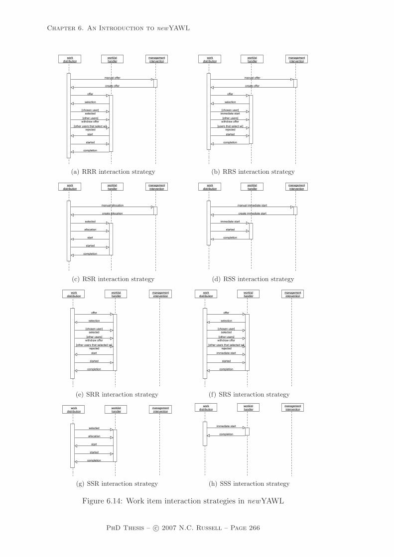
Chapter 6. An Introduction to newYAWL
(a) RRR interaction strategy (b) RRS interaction strategy
(c) RSR interaction strategy (d) RSS interaction strategy
(e) SRR interaction strategy (f) SRS interaction strategy
(g) SSR interaction strategy (h) SSS interaction strategy
Figure 6.14: Work item interaction strategies in newYAWL
PhD Thesis – c© 2007 N.C. Russell – Page 266

Chapter 6. An Introduction to newYAWL
where users is the base population from whom the final set of users to whomthe work item will be distributed will be chosen, org-groups is the hierarchyof organizational groups to which users can belong, jobs indicates the job roleswithin the organization and user-jobs maps individual users to the jobs that theyperform. The function returns a set of users to whom the work item should berouted.
Capability-based distributionCapabilities can be specified for each user which describe the qualities that theypossess that may be of relevance in making routing decisions. A capability-baseddistribution function can be specified for each task which allows user capabilitiesto be used in making work distribution decisions. The function takes the followingform.
function function-name users user-capabilities
where users is the base population from whom the final set of users to whom thework item will be distributed will be chosen and user-capabilities is the list ofcapabilities that each user possesses. The function returns a set of users to whomthe work item should be routed.
Historical distributionA historical distribution function can be specified for each task which allowshistorical data – essentially the content of the execution log – to be used inmaking work distribution decisions. The function takes the following form.
function function-name users events
where users is the base population from whom the final set of users to whom thework item will be distributed will be chosen and events are the list of recordsmaking up the process log. The function returns a set of users to whom the workitem should be routed.
6.3.3 Additional routing constraints
There are several additional constraints supported by newYAWL that can be usedto further refine the manner in which work items are routed to users. They areused in conjunction with the routing and interaction strategies described above.
Retain familiarThis constraint on a task overrides any other routing strategies and allows a workitem associated with it to be routed to the same user that undertook a work itemassociated with a specified preceding task in the same process instance. Where thepreceding task has been executed several times within the same process instance(e.g. as part of a loop), it is routed to one of the users that undertook a precedinginstance of the task.
Four eyes principleThis constraint on a task operates in essentially the reverse way to the Retainfamiliar constraint. It ensures that the potential users to whom a work itemassociated with a task is routed does not include the user that undertook a work
PhD Thesis – c© 2007 N.C. Russell – Page 267
Chapter 6. An Introduction to newYAWL
item associated with a nominated preceding task in the same process instance.Where the preceding task has been executed several times within the same processinstance, it cannot be routed to any of the users that undertook a precedinginstance of the task.
Random allocationThis constraint on a task ensures that any work items associated with it are onlyever routed to a single user where the user is selected from a group of potentialusers on a random basis.
Round robin allocationThis constraint on a task ensures that any work items associated with it are onlyever routed to a single user where the user is selected from a group of potentialusers on a cyclic basis such that each of them execute work items associatedwith the task the same number of times (i.e. the distribution is intended to beequitable).
Shortest queue allocationThis constraint on a task ensures that any work items associated with it are onlyever routed to a single user where the user is selected from a group of potentialusers on the basis of which of them has the shortest work queue.
6.3.4 Advanced user operating modes
newYAWL supports two advanced operating modes for user interaction withthe system. These modes are intended to expedite the throughput of work byimposing a defined protocol on the way in which the user interacts with thesystem and work items are allocated to them. These modes are described below.
Chained executionChained execution is essentially an operating mode that a given user can chooseto enable. Once they do this, upon the completion of a given work item in aprocess, should any of the immediately following tasks in the process instancehave potential to be routed to the same user (or to a group of users that includethe user), then these routing directives are overridden and the associated workitems are placed in the user’s work list with a started status.
Piled executionPiled execution is another operating mode however it operates across multipleprocess instances. It is enabled for a specified user-task combination and onceinitiated, it overrides any routing directive for the nominated task and ensuresthat any work items associated with the task in any process instance are routedto the nominated user.
6.3.5 Runtime privileges
newYAWL provides support for a number of privileges that can be enabled ona per-user basis that affect the way in which work items are distributed and thevarious interactions that the user can initiate to otherwise change the normal
PhD Thesis – c© 2007 N.C. Russell – Page 268

Chapter 6. An Introduction to newYAWL
manner in which the work item is handled. These are summarized in Table 6.2.Additionally, there are also privileges that can be enabled for users on a per taskbasis. These are summarized in Table 6.3.
Privilege Explanationchoose The ability to select the next work item to start execution onconcurrent The ability to execute more than one work item simultane-
ouslyreorder The ability to reorder items in the work listviewoffers The ability to view work items offered to other usersviewallocs The ability to view work items allocated to other usersviewexecs The ability to view work items started by other userschainedexec The ability to enter the chained execution operating mode
Table 6.2: User privileges supported in newYAWL
Privilege Explanationsuspend The ability for a user to suspend execution of work items
corresponding to this taskreallocate The ability for the user to reallocate work items corre-
sponding to this task (which have been commenced) toother users without any implied retention of state
reallocate state The ability for the user to reallocate work items corre-sponding to this task (which have been commenced) toanother user and retain the state of the work item
deallocate The ability for the user to deallocate work items cor-responding to this task (which have not yet been com-menced) and cause them to be re-allocated
delegate The ability for the user to delegate work items correspond-ing to this task (which have not yet been commenced) toanother user
skip The ability for the user to skip work items correspondingto this task
piledexec The ability to enter the piled execution operating modefor work items corresponding to this task
Table 6.3: User task privileges supported in newYAWL
6.4 Exception handling perspective
The generic graphical exception language presented in Chapter 5 has recentlybeen implemented for the YAWL System37. It provides comprehensive exceptionhandling capabilities based on the language proposal presented earlier. A detaileddiscussion of the architecture of this solution, the approach taken to implementa-tion and a formalization can be found in Adams’ PhD thesis [Ada07] which uses
37Further details on this release – YAWL Beta 8 – can be found at www.yawl-system-com.
PhD Thesis – c© 2007 N.C. Russell – Page 269
Chapter 6. An Introduction to newYAWL
Activity Theory as the basis for the development of an integrated approach for“dynamic and extensible flexibility, evolution and exception handling in work-flows, based not on proprietary frameworks, but on accepted ideas of how peopleactually perform their work activities” (p. iii).
As part of this work, Adams establishes the notion of worklets, small self-contained processes that fulfill a specific function. In conjunction with the work-lets is an extensible “ripple down” rule set that allows a task to be substitutedat runtime with a subprocess from the collection of worklets associated withthe process where an exception is detected or a need for task adaptation arises.There is also provision for the addition of new worklets at runtime (i.e. workflowextensions) where a suitable one cannot be located.
The exception handling capability implemented by Adams is based on thenotion of exlets which describe the set of steps to be taken to handle an identi-fied exception. The language primitives which describe an exlet are based on thelanguage primitives described in Section 5.3 although the rollback, reoffer andreallocate primitives are not included as Adams argues that these are data andresource-related constructs and outside of the control-flow focus of his exlet ap-proach. Seven different types of exception can be handled by the exlet capability(including two of those identified in Section 5.1.1). Both expected and unex-pected exceptions are catered for in real time and where a suitable exlet cannotbe located for an exception, it can be created dynamically.
Adams proposes a formalization, in the form of a CP-net, for the exceptionhandling process thus providing a complete semantic definition of its operationalthough it does not include a formal syntax for specifying exception handlingstrategies and does not directly correspond to the semantic model which will bepresented in Chapter 8. It is intended that any subsequent implementation ef-forts of the newYAWL language will incorporate the existing YAWL architectureincluding the exception handling facilities developed to date.
6.5 Summary
This chapter has provided an overview of the features provided by newYAWL,a reference language for specifying business processes based on the control-flow,data and resource patterns and the graphical exception language presented inPart One of this thesis. In the next chapter, an abstract syntax for a newYAWLis defined.
PhD Thesis – c© 2007 N.C. Russell – Page 270

Chapter 7. Syntax
Chapter 7
Syntax
This chapter presents an abstract syntax for the newYAWL reference language.The syntax facilitates the capture of all aspects of the control-flow, data andresource perspectives of a newYAWL business process model38. The aim of thesyntax is twofold. First, to provide complete coverage of the constructs that makeup the newYAWL reference language. Secondly, to do so in sufficient detail,that it is possible to directly enact a newYAWL process on the basis of theinformation captured about it in the abstract syntax model. The manner inwhich a newYAWL syntactic model is prepared for enactment is illustrated inFigure 7.1.
completenew
initial markingtransformation
functionsmarking
functionsYAWLof
semantic modelYAWLnew
specification
core
specificationnewYAWL
Figure 7.1: Preparing a newYAWL process model for enactment
A complete newYAWL specification corresponds to an instance of the abstractsyntax. Details of the abstract syntax are presented in Section 7.1. However it isnot necessary to describe the enactment of the newYAWL language in terms ofall of the constructs that it contains. Most of the new control-flow constructs innewYAWL can be transformed into existing YAWL constructs without any lossof generality. This approach to enactment has two advantages: (1) the existingYAWL engine can be used as the basis for executing newYAWL processes and(2) the existing verification techniques established for the control-flow perspectiveof YAWL continue to be applicable for newYAWL. The transformation of thenewYAWL control flow constructs into YAWL constructs occurs using a seriesof transformation functions. These are described both informally and formallyin Section 7.2. The resultant process model after transformation is called a corenewYAWL specification.
The manner in which a newYAWL specification is ultimately enacted is thesubject of Chapter 8 which presents an operational semantics for newYAWL based
38As the exception handling perspective for YAWL has been formalized and implementedelsewhere [Ada07], and exception handling in newYAWL is directly based on this work, it isnot included in the abstract syntax presented in this chapter.
PhD Thesis – c© 2007 N.C. Russell – Page 271

Chapter 7. Syntax
on CP-nets. A core newYAWL specification can be prepared for enactment bymapping it to an initial marking of the newYAWL semantic model. The activitiesassociated with transforming a core newYAWL specification to an initial markingof the semantic model are defined via a series of marking functions which aredescribed in Section 7.3.
7.1 Abstract syntax for newYAWL
This section presents a complete abstract syntax for all language elements innewYAWL39. As described earlier, newYAWL assumes the same conceptual basisas YAWL, and includes all of its language constructs. A newYAWL specificationis a set of newYAWL-nets which form a rooted graph structure. It also has anOrganizational model associated with it that describes the various resources thatare available to undertake work items and the relationships that exist betweenthem in an organizational context. Each newYAWL-net has a Data passing modelassociated with it that describes how data is passed between constructs within theprocess specification. Each newYAWL-net is composed of a series of tasks. In or-der to specify how each task will actually be distributed to specific resources whenit is enacted, a Work distribution model is associated with each newYAWL-net.All of these notions are now formalized, starting with the newYAWL specification.
Definition 1. (newYAWL Specification) A newYAWL specification is a tu-ple = (NetID, ProcessID, FolderID, TaskID, MITaskID, ScopeID, VarID, Trig-gerID, TNmap, NYmap, STmap, VarName, DataType, VName, DType, Var-Type, VGmap, VFmap, VCmap, VBmap, VSmap, VTmap, VMmap, PushAl-lowed, PullAllowed) such that:
(* global objects *)– NetID is the set of net identifiers (i.e. the top-level process together with all
subprocesses);– ProcessID ∈ NetID is the process identifier (i.e. the top-level net);– FolderID is the set of identifiers of data folders that can be shared among a
selected group of cases;– TaskID is the set of task identifiers in nets;– MITaskID ⊆ TaskID is the set of identifiers of multiple instance tasks;– ScopeID is the set of scope identifiers which group tasks within nets;– VarID is the set of variable identifiers used in nets;– TriggerID is the set of trigger identifiers used in nets;
(* decomposition *)– TNmap : TaskID 9 NetID defines the mapping between composite tasks and
their corresponding subprocess decompositions which are specified in the formof a newYAWL-net, such that for all t, TNmap(t) yields the NetID of thecorresponding newYAWL-net, if it exists;
39In doing so it utilizes a number of non-standard mathematical notations. These are ex-plained in further detail in Appendix B
PhD Thesis – c© 2007 N.C. Russell – Page 272

Chapter 7. Syntax
– NYmap : NetID → newYAWL-nets, i.e. each net has a complete description ofits contents such that for all n ∈ NetID, NYmap(n) is governed by Definition2 where the notation Tn denotes the set of tasks that appear in a net n. Tasksare not shared between nets hence ∀m,n∈NetID [Tm ∩ Tn 6= ∅⇒ m = n]. TaskIDis the set of tasks used in all nets and is defined as TaskID =
⋃n∈NetID Tn;
– In the directed graph defined by G = (NetID , {(x , y) ∈ NetID × NetID |∃t∈Tx [t ∈ dom(TNmap) ∧ TNmap(t) = y]}) there is a path from ProcessID toany node n ∈ NetID ;
– STmap : ScopeID → P+(TaskID) such that ∀s∈ScopeID∃n∈NetID [STmap(s) ⊆ Tn]i.e. a scope can only contain tasks within the same net;
(* variables *)
– VarName is the set of variable names used in all nets;– DataType is the set of data types;– VName : VarID → VarName identifies the name for a given variable;– DType : VarID → DataType identifies the underlying data type for a variable;– VarType : VarID → {Global ,Folder ,Case,Block , Scope,Task ,MI } describes
the various variable scopings that are supported. The notation VarIDx ={v ∈ VarID | VarType(v) = x} identifies variables of a given type;
– VGmap ⊆ VarIDGlobal , identifies global variables that are associated with theentire process;
– VFmap : VarIDFolder → FolderID identifies the folder to which each foldervariable corresponds, such that dom(VFmap) = VarIDFolder and∀v1,v2∈dom(VFmap)[VName(v1) = VName(v2) ⇒ (v1 = v2 ∨ VFmap(v1) 6=VFmap(v2))], i.e. folder variable names are unique within a given folder;
– VCmap ⊆ VarIDCase identifies the case variables for the process;– VBmap : VarIDBlock → NetID identifies the specific net to which each block
variable corresponds, such that dom(VBmap) = VarIDNet ;– VSmap : VarIDScope → ScopeID identifies the specific scope to which each scope
variable corresponds, such that dom(VSmap) = VarIDScope ;– VTmap : VarIDTask → TaskID identifies the specific task to which a task vari-
able corresponds, such that dom(VTmap) = VarIDTask ;– VMmap : VarIDMI → MITaskID identifies the specific task to which each
multiple-instance variable corresponds, such that dom(VMmap) = VarIDMI ;– PushAllowed ⊆ VarID identifies those variables that can have their values
updated from external data locations;– PullAllowed ⊆ VarID identifies those variables that can have their values read
from external data locations;
Having described the global characteristics of a newYAWL specification, we cannow proceed to the definition of a newYAWL-net. Note that newYAWL-nets isthe set of all instances governed by Definition 2.
Definition 2. (newYAWL-net) A newYAWL-net is a tuple (nid, C, i, o, T,TA, TC, M, F, Split, Join, Default, <XOR, Rem, Comp, Block, Nofi, Disable,Lock, Thresh, ThreadIn, ThreadOut, ArcCond, Pre, Post, PreTest, PostTest,WPre, WPost, Trig, Persist) such that:
PhD Thesis – c© 2007 N.C. Russell – Page 273

Chapter 7. Syntax
(* basic control-flow elements *)
– nid ∈ NetID is the identity of the newYAWL-net ;– C is a set of conditions;– i ∈ C is the input condition;– o ∈ C is the output condition;– T is the set of tasks;– TA ⊆ T is the set of atomic tasks;– TC ⊆ T is the set of composite tasks;– TA and TC form a partition over T ;– M ⊆ T is the set of multiple instance tasks;– F ⊆ (C \ {o} × T ) ∪ (T × C \ {i}) ∪ (T × T ) is the flow relation, such that
every node in the graph (C ∪ T, F ) is on a directed path from i to o;– Split : T 9 {AND ,XOR,OR,THREAD} specifies the split behaviour of each
task, such that ∀t∈dom(Split)[Split(t) = THREAD ⇒ | t • | = 1], i.e. thread splitscan only have one output arc;
– Join : T 9 {AND ,XOR,OR,PJOIN ,THREAD} specifies the join behaviourof each task such that ∀t∈dom(Join)[Join(t) = THREAD ⇒ |•t | = 1], i.e. threadmerges can only have one input arc;
– Default ⊆ F , Default : dom(Split B {OR,XOR}) → T ∪ C denotes the defaultarc for each OR-split and XOR-split.
– <XOR⊆ {t ∈ T | Split(T ) = XOR}×P(T∪C)×(T∪C) describes the evaluationsequence of outgoing arcs from an XOR-split such that for any (t, V ) ∈<XOR wewrite <t
XOR= V and V is a strict total order over t• = {x ∈ T ∪C | (t, x) ∈ F}.Link conditions associated with each arc are evaluated in this sequence untilthe first evaluates to true. If none evaluate to true, the default arc indicated byDefault(t) is selected, thus ensuring that exactly one outgoing arc is enabled;
– Rem : T 9 P+(T ∪ C\{i, o}) specifies the additional tokens to be removed byemptying a part of the net and tasks that should be cancelled as a consequenceof an instance of this task completing execution;
– Comp : T 9 P+(T ) specifies the tasks that are force completed as a conse-quence of the completion of an instance of this task completing execution;
– Block : T 9 P+(T ) where t ∈ dom(Block) ⇔ Join(t) = PJOIN , specifies thetasks that are blocked after the firing of a partial join task prior to its resetsuch that ∀t∈dom(Block) t /∈ Block(t);
– Nofi : M → N×Ninf ×Ninf ×{dynamic, static}×{cancelling , non-cancelling}specifies the multiplicity of each task – in particular the lower and upper boundof instances to be created at task initiation, the threshold for continuationindicating how many instances must complete for the thread of control to bepassed to subsequent tasks, whether additional instances can be created “onthe fly” once the task has commenced and whether partial synchronizationresults in remaining instances being cancelled or not;
– Disable : T → P+(M) specifies the multiple-instance tasks that are disabledfrom creating further instances as a consequence of an instance of this taskcompleting execution.
(* locks *)
– Lock : T → P(VarID) is a function mapping tasks to the data elements thatthey require locks on during execution;
PhD Thesis – c© 2007 N.C. Russell – Page 274

Chapter 7. Syntax
(* partial joins *)– Thresh : T 9 N where t ∈ dom(Thresh) ⇔ Join = PJOIN and∀t∈dom(Thresh) [1 ≤ Thresh(t) < | • t |] identifies the firing threshold for partial(i.e. n-out-of-m type) joins;
(* thread splits and joins *)– ThreadIn : T 9 NatExpr where dom(ThreadIn) = dom(Join B {THREAD})
identifies the number of incoming threads that the task requires in order tofire;
– ThreadOut : T 9 NatExpr where dom(ThreadOut) = dom(SplitB{THREAD})identifies the number of outgoing threads that the task generates on firing;
(* conditions on arcs *)
– ArcCond : F ∩ (dom(Split B{XOR,OR})× (T ∪C)) → BoolExpr identifies thespecific condition associated with each branch of an OR or XOR split.
(* pre/post conditions and pre/post tests for task iteration *)
– Pre : T 9 BoolExpr is a function identifying tasks which have a preconditionassociated with them;
– Post : T 9 BoolExpr is a function identifying tasks which have a postconditionassociated with them;
– PreTest : T 9 BoolExpr is a function identifying tasks which have an itera-tion pre-test condition associated with them. Where this condition is met, atenablement the task is executed otherwise it is skipped;
– PostTest : T 9 BoolExpr is a function identifying tasks which have an iterationpost-test condition associated with them. Where this condition is not met attask completion, the task is repeated otherwise it completes execution;
– WPre ∈ BoolExpr indicates the precondition for commencement of a processinstance;
– WPost ∈ BoolExpr indicates the postcondition for completion of a processinstance;
(* triggers *)
– Trig : T 9 TriggerID identifies tasks which have a trigger associated withthem;
– Persist ⊆ dom(Trig) identifies the subset of triggers which are persistent;
Each newYAWL-net is identified by a unique nid. As for YAWL, the tuple(C,T,F) takes its form from classical Petri nets where C corresponds to the set ofconditions, T to the set of tasks and F to the flow relation (i.e. the directed arcsbetween conditions and tasks). However there are two distinctions: (1) i and odescribe specific conditions that denote the start and end condition for a net and(2) the flow relation allows for direct connections between tasks in additional tolinks from conditions to tasks and tasks to conditions.
Expressions are denoted informally via Expr which identifies the set of expres-sions relevant to a newYAWL-net. It may be divided into a number of disjointsubsets including BoolExpr, IntExpr, NatExpr, StrExpr and RecExpr, these be-ing the sets of expressions that yield Boolean, integer, natural number, string
PhD Thesis – c© 2007 N.C. Russell – Page 275

Chapter 7. Syntax
and record-based results when evaluated. There is also recognition for work dis-tribution purposes of capability-based, historical and organizational distributionfunctions that are denoted by the CapExpr, HistExpr and OrgExpr subsets ofExpr respectively.
As already indicated, one of the major features of newYAWL is the inclusionof the data perspective. In order to facilitate the utilization of data elementsduring the operation of the process, it is necessary to define a model to describethe way in which data is passed between active process components.
Definition 3. (Data passing model) Within the context of a newYAWL-net nid , there is a data passing model (InPar, OutPar, OptInPar, OptOutPar,MIInPar, MIOutPar, InNet, OutNet, OptInNet, OptOutNet, InProc, OutProc,OptInProc, OptOutProc) with the following components:
(* data passing to/from atomic tasks *)– InPar : TA × VarID 9 Expr is a function identifying the input parameter
mappings to a task at initiation, such that ∀(t,v)∈dom(InPar)[VTmap(v) = t];– OutPar : TA × VarID 9 Expr is a function identifying the output parameter
mappings from a task at completion, such that ∀(t,v)∈dom(OutPar) [v ∈ VarIDGlobal
∪VarIDFolder ∪VarIDCase ∨ t ∈ TVBmap(v)∪STmap(VSmap(v))], i.e. the outputvariable can be a global, case or folder variable, a block variable correspondingto this net or a scope variable in the same scope as the task;
– OptInPar ⊆ dom(InPar) identifies those input mappings to a task which areoptional;
– OptOutPar ⊆ dom(OutPar) identifies those output mappings to a task whichare optional;
(* data passing between composite tasks and subprocess decompositions *)– InNet : TC×VarID 9 Expr is a function identifying the input parameter map-
pings to the subprocess corresponding to a composite task at commencement,such that ∀(t,v)∈dom(InNet) [VBmap(v) = TNmap(t)];
– OutNet : TC × VarID 9 Expr is a function identifying the output parametermappings from a subprocess decomposition to its parent composite task at com-pletion, such that ∀(t,v)∈dom(OutPar) [v ∈ VarIDGlobal ∪VarIDFolder ∪VarIDCase ∨t ∈ TVBmap(v) ∪ STmap(VSmap(v))], i.e. the output variable can be a global,case or folder variable, a block variable corresponding to this net or a scopevariable in the same scope as the task;
– OptInNet ⊆ dom(InNet) identifies those input mappings to a subprocess whichare optional;
– OptOutNet ⊆ dom(OutNet) identifies those output mappings from a subpro-cess which are optional;
(* data passing to/from multiple-instance tasks *)– MIInPar : TaskID × P(VarID) 9 RecExpr is a function identifying the input
parameter mapping for each instance of a multiple instance task at commence-ment, such that ∀(t,v)∈dom(MIInPar)[t ∈ dom(Nofi) ∧ VMmap(v) = t];
– MIOutPar : TaskID × VarID 9 RecExpr is a function identifying output pa-rameter mappings from the various multiple instance tasks at completion, suchthat ∀(t,v)∈dom(OutPar) [t ∈ TVBmap(v) ∪ STmap(VSmap(v)) ∨ v ∈ VarIDGlobal ∪
PhD Thesis – c© 2007 N.C. Russell – Page 276
Chapter 7. Syntax
VarIDFolder ∪ VarIDCase ], i.e. the output variable can be a scope variable inthe same scope as the task, a block variable corresponding to this net or anyglobal, folder or case variable;
(* data passing to/from nets *)– InProc : VarID 9 Expr is a function identifying the input parameter mappings
to a process instance at commencement, such that ∀v∈dom(InProc)[(VarType(v) =Scope ∧ STmap(VSmap(v)) ⊆ TProcessID) ∨ (VarType(v) = Block ∧VBmap(v) = ProcessID) ∨ VarType(v) = Case], i.e. the parameter value canonly be mapped to a scope or block variable in the top level net or a casevariable;
– OutProc : VarID 9 Expr is a function identifying output parameter mappingsfrom a process instance at completion, such that ∀v∈dom(OutProc)[VarType(v)∈ {Global ,Folder}], i.e. the parameter value can only be mapped to a folderor global variable;
– OptInProc ⊆ dom(InProc) identifies optional input mappings to a process;– OptOutProc ⊆ dom(OutProc) identifies optional output mappings from a pro-
cess;
newYAWL also incorporates a comprehensive characterization of the resourceperspective. This characterization is composed of two main components: theOrganizational model which provides a description of the overall structure ofthe organization in terms of organizational groups, users, jobs and reportinglines and the Work distribution model which defines the manner in which workitems are distributed to users at runtime for execution as well as identifying theinteractions that individual users are able to invoke to influence the way in whichthis distribution occurs. These two models are specified in more detail below.
Definition 4. (Organizational model) Within the context of a newYAWLspecification ProcessID , there is an organizational model described by the tu-ple (UserID, RoleID, CapabilityID, OrgGroupID, JobID, CapVal, RoleUser, Org-GroupType, GroupType, JobGroup, OrgStruct, Superior, UserQual, UserJob) asfollows:
(* basic definitions *)– UserID is the set of all individuals to whom work items can be distributed;– RoleID is the set of designated groupings of those users;– CapabilityID is the set of qualities that a user may possess that are useful when
making work distribution decisions;– OrgGroupID is the set of groups within the organization;– JobID is the set of all jobs within the organization;– CapVal is the set of values that a capability can have;
(* organizational definition *)– RoleUser : RoleID → P(UserID) indicates the set of users in a given role;– OrgGroupType = {team, group, department , branch, division, organization}
identifies the type of a given organizational group;– GroupType : OrgGroupID → OrgGroupType;– JobGroup : JobID → OrgGroupID indicates which group a job belongs to;
PhD Thesis – c© 2007 N.C. Russell – Page 277
Chapter 7. Syntax
– OrgStruct : OrgGroupID 9 OrgGroupID forms an acyclic intransitive graphwith a unique root which identifies a composition hierarchy for groups;
– Superior : JobID 9 JobID forms an acyclic intransitive graph which identifiesthe reporting lines between jobs;
(* user definition *)– UserQual : UserID × CapabilityID → CapVal identifies the capabilities that a
user possesses;– UserJob : UserID → P(JobID) maps a user to the jobs that they hold;
The newYAWL organizational model takes the form of a tree, based on thereporting relationships between groups where the most senior group within theorganization is the root node of the tree. This model is deliberately chosen to besimple and generic so that it applies to a relatively broad range of situations inwhich newYAWL may be used. Finally, the Work distribution model is presentedthat captures the various ways in which work items are distributed to users andany constraints that need to be taken into account when doing so.
Definition 5. (Work distribution model) Within the context of a newYAWL-net nid , it is possible to describe the manner in which work items are distributedto users for execution. A work distribution model is a tuple (Auto, TM , Initiator,DistUser, DistRole, DistVar, SameUser, FourEyes, HistDist, OrgDist, CapDist,UserSel, UserPriv, UserTaskPriv) as follows:
(* work allocation *)– Auto ⊆ TA is the set of tasks which execute automatically without user inter-
vention, where TA is the set of atomic tasks;– TM ⊆ TA\Auto is the set of atomic tasks that must be allocated to users for
execution;– Initiator : TM → {system, resource} × {system, resource} × {system, resource}
indicates who initiates the offer, allocate and commence actions;– DistUser : TM 9 P(User) identifies the users to whom a task should potentially
be distributed;– DistRole : TM 9 P(Role) identifies the roles to whom a task should potentially
be distributed;– DistVar : TM 9 P(VarID) identifies a set of variables holding either user or
roles to whom a task should potentially be distributed;– dom(DistUser), dom(DistRole) and dom(DistVar) form a partition over TM ;– SameUser : TM 9 TM is an irreflexive function that identifies that a task should
be executed by one of the same users that undertook another specified task inthe same case;
– FourEyes : TM 9 TM is an irreflexive function that identifies a task that shouldbe executed by a different user to the one(s) that executed another specifiedtask in the same case;
– HistDist : TM 9 HistExpr identifies a set of historical criteria that users thatexecute the task must satisfy;
– OrgDist : TM 9 OrgExpr identifies a set of organizational criteria that usersthat execute the task must satisfy;
PhD Thesis – c© 2007 N.C. Russell – Page 278

Chapter 7. Syntax
– CapDist : TM 9 CapExpr identifies a set of capabilities that users that executethe task must possess;
– UserSel : TM 9 {random, round -robin, shortest-queue} indicates how a specificuser who will execute a task should be selected from a group of possible users;
(* user privilege definition *)– UserPriv : UserID 9 P(UserAuthKind) indicates the privileges that an indi-
vidual user possesses, where UserAuthKind = {choose, concurrent, reorder,viewoffers, viewallocs, viewexecs, chainedexec};
– UserTaskPriv : UserID ×TaskID 9 P(UserTaskAuthKind) indicates the priv-ileges that an individual user possesses in relation to a specific task, whereUserTaskAuthKind = {suspend, start, reallocate, reallocate state, deallocate,piledexec, delegate,skip};
7.2 From complete to core newYAWL
The complete capabilities of newYAWL are captured by Definitions 1 to 5 of theabstract syntax. Several of the new constructs can be seen in terms of otherconstructs and thus can be eliminated through structural transformations to thenewYAWL specification in which they occur, thus minimizing the need to extendthe underlying execution environment. In this section, we present six distinctsets of transformations that simplify a newYAWL specification and allow theseconstructs to be directly embodied within a refinement of the model in whichthey were originally captured. The specific language elements that are addressedby these transformations are as follows:
• Persistent and transient triggers;
• While, repeat and combination loops;
• Thread merges;
• Thread splits;
• Partial joins; and
• Tasks directly linked to tasks.
Each of these transformations is described in the following section, first viaa high-level graphical illustration of its operation and then more completely us-ing set theory. The order in which the transformations are applied is materialas later transformations assume that some structural modifications enacted byearlier transformations have been completed. For this reason, the transforma-tions should be applied in the order presented in this chapter. Once a completenewYAWL specification has been appropriately simplified through the applicationof these transformations, it is known as a core newYAWL specification. Addition-ally, in order to preserve the integrity of the specification being transformed, thetransformations are not applied to all constructs in a specification simultaneouslybut rather on an incremental (i.e. item-by-item) basis. The transformations are
PhD Thesis – c© 2007 N.C. Russell – Page 279

Chapter 7. Syntax
applied iteratively for a given specification until all constructs have been appro-priately dealt with. Note that in the interest of brevity, for all transformationswe only describe changes to the elements in each specification. Elements thatremain unchanged are omitted. The final core newYAWL specification is ob-tained by aggregating the latest version of each of the models for the newYAWLspecification, newYAWL-nets, Data passing model, Work distribution model andOrganizational model once all transformations have been applied.
The transformations presented are semantics-defining and give an opera-tional meaning to the higher-level newYAWL constructs embodied in a completenewYAWL specification by defining their function in terms of core newYAWLconstructs. As such, they cannot be seen as equivalence-preserving and it is im-portant to note that whilst some of the transformations appear to change themoment of choice for some constructs in a complete newYAWL specification, infact there can be no direct meaning ascribed to such a specification and it is onlywhen it is appropriately transformed to a core newYAWL specification that theactual moment of choice for these constructs is revealed.
7.2.1 Persistent and transient triggers
Persistent and transient triggers that are defined for tasks in newYAWL specifi-cations are operationalized in core newYAWL specifications as specific tasks thatidentify when the trigger has been received. Figure 7.2 illustrates that mannerin which a trigger is incorporated into a newYAWL specification. In essence,the trigger trig associated with task A becomes the task AT1. This task is onlyenabled when the process instance is running (signified by a token in place CT )and triggers received for the task are collected in condition CA. Any relevant joinassociated with task A is moved into a dedicated task which proceeds it. Theenablement of task A then becomes an AND-join based on the normal threadof control and the condition that collects tokens (CA). The actual transforma-tion for persistent and transient triggers is identical except that transient triggershave the additional requirement that a means of deleting the trigger is requiredif it cannot be utilized immediately. This is provided via reset task AT2 as illus-trated in Figure 7.2 which is associated with the condition which collects tokensfor triggers that are received. Once a trigger has been received, there is a racecondition between the enablement of the task being (A) triggered and the resettask (AT2) thus ensuring that any tokens that do not immediately trigger task Aare discarded40.
As the transformation involves the addition of both tasks and conditions aswell as changes to the flow relation, it necessitates changes to the newYAWLspecification and to each newYAWL-net which includes a trigger. There are alsominor changes to the Data passing model to provide task AT3 with access to thedata provided by the input parameters in order to allow the task precondition (ifany) to be evaluated41. There are also changes to the Work distribution model
40In practice, this task would have a delay associated with its enablement to ensure that taskA has first option to utilize any tokens that may be delivered to condition CA before they arediscarded.
41Note that where a task is split into several parts by a transformation, the precondition is
PhD Thesis – c© 2007 N.C. Russell – Page 280

Chapter 7. Syntax
JOIN
SP
LIT
CT
CA
C i Co
nid
AT1
D
transient triggersonly required for CC
A
T2A
AT3JOIN
SP
LIT
A
A
Enid TT
start end
S
Figure 7.2: Persistent and transient trigger transformation
to ensure that any tasks added by the transformation are automatic (i.e. theydo not need to be allocated to a user for execution). The newYAWL specifi-cation is amended to include any new tasks added during steps 1 and 2 of thetransformation and also to add them to any scopes to which they might apply.
The transformation has five steps. First of all, the general extensions are madeto each newYAWL-net that includes triggers. These extensions accommodate alltrigger transformations in a given newYAWL-net and hence only need to be madeonce. The next step is to transform each trigger into core newYAWL constructs.The final three steps amend the Data passing model, Work distribution modeland newYAWL specification. The Organizational model is unchanged.
Step 1: Initial transformations for newYAWL-net nid with triggers
precondition: dom(Trig) 6= ∅C ′ = C ∪ {CT , Cstart, Cend}i′ = Cstart
evaluated both for the first task into which it is split and it is also retained for the original task.The postcondition is retained for the original task and replicated for the last task into whichthe task is split. Locking requirements and parameters are also replicated as required.
PhD Thesis – c© 2007 N.C. Russell – Page 281

Chapter 7. Syntax
o′ = Cend
T ′ = T ∪ {TSnid, TEnid
}T ′
A = TA ∪ {TSnid, TEnid
}F ′ = F ∪ {(Cstart, TSnid
), (TSnid, i), (TSnid
, CT ), (CT , TEnid), (o, TEnid
), (TEnid, Cend)}
Join′ = Join ∪ {(TEnid,AND)}
Split′ = Split ∪ {(TSnid,AND)}
Step 2: Transformations for newYAWL-net nid′ (resulting from step1) to replace individual triggers with core newYAWL constructs
Let t ∈ dom(Trig ′), transforming t in net nid ′ leads to the following changes:
C ′′ = C ′ ∪ {Ct, Dt}T ′′ = T ′ ∪ {tT1, tT3} ∪ {xT2 | x ∈ dom(Trig ′)\Persist ′ ∧ x = t}T ′′
A = T ′A ∪ {tT1, tT3} ∪ {xT2 | x ∈ dom(Trig ′)\Persist ′ ∧ x = t}
F ′′ = (F ′\ {(x, t) | x ∈ •t})∪ {(x, tT3) | x ∈ •t}∪ {(CT , tT1), (tT1, CT ), (tT1, Ct), (Ct, t), (tT3, Dt), (Dt, t)}∪ {(Cx, xT2) | x ∈ dom(Trig ′)\Persist ′ ∧ x = t}∪ {(CT , xT2) | x ∈ dom(Trig ′)\Persist ′ ∧ x = t}∪ {(xT2, CT ) | x ∈ dom(Trig ′)\Persist ′ ∧ x = t}
Join ′′ = (Join ′\{(x, Join ′(x)) | x ∈ dom(Join ′) ∧ x = t})∪ {(xT3, Join
′(x)) | x ∈ dom(Join ′) ∧ x = t}∪ {(t,AND)}∪ {(xT2,AND) | x ∈ dom(Trig ′)\Persist ′ ∧ x = t}
Split ′′ = Split ′ ∪ {(tT1,AND)}Rem ′′ = (Rem ′\{(x,Rem ′(x)) | x ∈ dom(Rem ′) ∧ t ∈ Rem ′(x)})
∪ {(x,Rem ′(x) ∪ {tT3, Dt}) | x ∈ dom(Rem ′) ∧ t ∈ Rem ′(x)})Block ′′ = ((Block ′\ {(x,Block ′(x)) | x ∈ dom(Block ′) ∧ x = t})
\ {(x,Block ′(x)) | x ∈ dom(Block ′) ∧ t ∈ Block ′(x)})∪ {(xT3,Block ′(x)) | x ∈ dom(Block ′) ∧ x = t}∪ {(x, ((Block ′(x)\{t}) ∪ {tT3})) | x ∈ dom(Block ′)
∧ t ∈ Block ′(x)}Lock ′′ = Lock ′ ∪ {(xT3,Lock ′(x)) | x ∈ dom(Lock ′) ∧ x = t}Thresh ′′ = (Thresh ′\ {(x,Thresh ′(x)) | x ∈ dom(Thresh ′) ∧ x = t})
∪ {(xT3,Thresh ′(x)) | x ∈ dom(Thresh ′) ∧ x = t}ThreadIn ′′ = (ThreadIn ′\ {(x,ThreadIn ′(x)) | x ∈ dom(ThreadIn ′) ∧ x = t})
∪ {(xT3,ThreadIn ′(x)) | x ∈ dom(ThreadIn ′) ∧ x = t}Pre ′′ = Pre ′ ∪ {(xT3,Pre ′(x)) | x ∈ dom(Pre ′) ∧ x = t}
PhD Thesis – c© 2007 N.C. Russell – Page 282

Chapter 7. Syntax
Trig ′′ = ∅Persist ′′ = ∅
Step 3: Transformations for Data passing model for newYAWL-net nid
Let t ∈ dom(Trig), transforming t in net nid leads to the following changes:
InPar ′ = InPar ∪ {((xT3, v), e) | x ∈ dom(Trig) ∧ ((x, v), e) ∈ InPar ∧ x = t}OptInPar ′ = OptInPar ∪ {(xT3, v) | x ∈ dom(Trig) ∧ (x, v) ∈ OptInPar ∧ x = t}
Step 4: Transformations for Work distribution model for newYAWL-net nid
Auto′ = Auto ∪ (T ′′nid \Tnid);
Step 5: Transformations for newYAWL specification
TaskID ′ =⋃
n∈NetID T ′′n
STmap ′ = (STmap\ {(s, STmap(s)) | s ∈ dom(STmap)
∧ STmap(s) ∩ dom(Trig) 6= ∅})∪ {(s, STmap(s) ∪ {tT3}) | s ∈ dom(STmap)
∧ t ∈ STmap(s) ∩ dom(Trig)}
7.2.2 Loops
Loops in newYAWL are based on PreTest and PostTest conditions associatedwith individual tasks. Depending on the combination of PreTest and PostTestassociated with a task and whether it has any join or split behaviour, there are aseries of alternate transformations that can be made in order to remove specificreliance on loop constructs in order to achieve task iteration. The various trans-formations are summarized in Figure 7.3. In essence, they involve varying theprocess model to construct looping structures with entry and/or exit conditionswhich are based on the conditions identified for the PreTests and PostTests42.
The specific transformations required are detailed below. They necessitatechanges to each of the individual newYAWL-nets that contain loops to sepa-rate the join and split behaviour which may be associated with tasks possess-ing PreTest and/or PostTest conditions from the looping behaviour. As thesetransformations potentially necessitate the addition of new tasks, there are alsochanges to the Data passing model to ensure that any new tasks have access tothe same data elements as the task from which they were derived and also tothe newYAWL specification. Any new tasks are automatic hence there are alsoamendments to the Work distribution model.
42Note that in the diagrams, ∼PreTest(A) is assumed to be the logical negation of PreTest(A).
PhD Thesis – c© 2007 N.C. Russell – Page 283
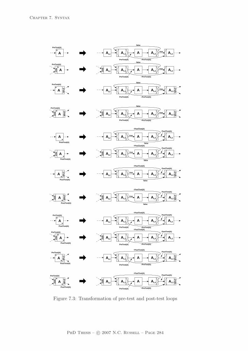
Chapter 7. Syntax
L1A
JOIN
L1A
L1A
JOIN
L1A
L1A
JOIN
L1A
L1A
JOIN
L1A
true
false
true
false
true
false
true
false
L1A true
false
~PreTest(A)PreTest(A)
PreTest(A)
PreTest(A)
PreTest(A)
JOIN
L1A true
false
L1A true
false
false
JOIN
L1A true
~PreTest(A)
~PreTest(A)
~PreTest(A)
~PostTest(A)
~PostTest(A)
~PostTest(A)
~PostTest(A)
~PostTest(A)
~PostTest(A)
~PostTest(A)
~PostTest(A)
PostTest(A)
PostTest(A)
PostTest(A)
PostTest(A)
PostTest(A)
PostTest(A)
PostTest(A)
~PreTest(A)
~PreTest(A)
~PreTest(A)
~PreTest(A)
PreTest(A)
PreTest(A)
PreTest(A)
PreTest(A)
PreTest(A)
PreTest(A)
PreTest(A)
PreTest(A)
PostTest(A)
PostTest(A)
PostTest(A)
PostTest(A)
PreTest(A)
PostTest(A)
PreTest(A)
PostTest(A)
PreTest(A)
PostTest(A)
PreTest(A)
PostTest(A)
PostTest(A)
SP
LIT
JOIN
SP
LIT
JOIN
SP
LIT
JOIN
SP
LIT
JOIN
JOIN A
A
A
A
A
A
A
A
A
A
A
A
AL2 A AL4 AL3
AL2 A AL4 AL3
AL2 A AL4 SP
LITAL3
AL2 A AL4 SP
LITAL3
AL2 A AL4 AL3
AL2 A AL4 AL3
AL2 A AL4 SP
LITAL3
AL2 A AL4 SP
LITAL3
AL2 A AL4 AL3
AL2 A AL4 SP
LITAL3
AL2 A AL4 SP
LITAL3
AL2 A AL4 AL3
JOIN
SP
LIT
SP
LIT
Figure 7.3: Transformation of pre-test and post-test loops
PhD Thesis – c© 2007 N.C. Russell – Page 284

Chapter 7. Syntax
Step 1: Transformations for newYAWL-net nid
Let t ∈ dom(PreTest) ∪ dom(PostTest), transforming t in net nid lead to thefollowing changes:
T ′ = T ∪ {tL1, tL2, tL3, tL4}T ′
A = TA ∪ {tL1, tL2, tL3, tL4}F ′ = (F\ {(c, t) | c ∈ •t} ∪ {(t, c) | c ∈ t•})
∪ {(c, tL2) | c ∈ •t} ∪ {(tL3, c) | c ∈ t•}∪ {(tL2, tL1), (tL1, t), (t, tL4), (tL1, tL3), (tL4, tL1), (tL4, tL3)}
Split′ = (Split\ {(x, Split(x)) | x ∈ dom(Split) ∧ x = t})∪ {(xL3, Split(x)) | x ∈ dom(Split) ∧ x = t}∪ {(tL1,XOR), (tL4,XOR)}
Join′ = (Join\ {(x, Join(x)) | x ∈ dom(Join) ∧ x = t})∪ {(xL2, Join(x)) | x ∈ dom(Join) ∧ x = t}∪ {(tL1,XOR), (tL3,XOR)}
Default ′ = (Default\ {(x,Default(x)) | x ∈ dom(Default)
∧ Split(x) ∈ {OR,XOR} ∧ x = t})∪ {(xL3,Default(x)) | x ∈ dom(Default)
∧ Split(x) ∈ {OR,XOR} ∧ x = t}∪ {(tL1, t), (tL4, tL3)}
<′XOR= (<XOR\{(x,<x
XOR) | x ∈ dom(Split) ∧ Split(x) = XOR ∧ x = t})∪ {(xL3, <
xXOR) | x ∈ dom(Split) ∧ Split(x) = XOR ∧ x = t}
∪ {(tL1, {(t, tL3)})} ∪ {(tL4, {(tL1, tL3)})}Rem ′ = ((Rem\ {(x,Rem(x)) | x ∈ dom(Rem) ∧ x = t})
\{(x,Rem(x)) | x ∈ dom(Rem) ∧ t ∈ Rem(x)})∪ {(xL3,Rem(x)) | x ∈ dom(Rem) ∧ x = t}∪ {(x,Rem(x) ∪ {tL1, tL2, tL3, tL4}) | x ∈ dom(Rem) ∧ t ∈ Rem(x)}
Comp ′ = (Comp\ {(x,Comp(x)) | x ∈ dom(Comp) ∧ x = t})∪ {(xL3,Comp(x)) | x ∈ dom(Comp) ∧ x = t}
Block ′ = ((Block\ {(x,Block(x)) | x ∈ dom(Block) ∧ x = t})\ {(x,Block(x)) | x ∈ dom(Block) ∧ t ∈ Block(x)})∪ {(xL2,Block(x)) | x ∈ dom(Block) ∧ x = t}∪ {(x, ((Block(x)\{t}) ∪ {tL2})) | x ∈ dom(Block)
∧ t ∈ Block(x)}Disable ′ = (Disable\ {(x,Disable(x)) | x ∈ dom(Disable) ∧ x = t})
∪ {(xL3,Disable(x)) | x ∈ dom(Disable) ∧ x = t}
PhD Thesis – c© 2007 N.C. Russell – Page 285

Chapter 7. Syntax
Lock′ = Lock ∪ {(xL1, Lock(x)) | x ∈ dom(Lock) ∧ x = t}∪ {(xL2,Lock(x)) | x ∈ dom(Lock) ∧ x = t}∪ {(xL3,Lock(x)) | x ∈ dom(Lock) ∧ x = t}∪ {(xL4, Lock(x)) | x ∈ dom(Lock) ∧ x = t}
Thresh ′ = (Thresh\ {(x,Thresh(x)) | x ∈ dom(Thresh) ∧ x = t})∪ {(xL2,Thresh(x)) | x ∈ dom(Thresh) ∧ x = t}
ThreadIn ′ = (ThreadIn\ {(x,ThreadIn(x)) | x ∈ dom(ThreadIn) ∧ x = t})∪ {(xL2,ThreadIn(x)) | x ∈ dom(ThreadIn) ∧ x = t}
ThreadOut ′ = (ThreadOut\ {(x,ThreadOut(x)) | x ∈ dom(ThreadOut) ∧ x = t})∪ {(xL3,ThreadOut(x)) | x ∈ dom(ThreadOut) ∧ x = t}
ArcCond ′ = (ArcCond\{((x, c),ArcCond(x, c)) | x ∈ dom(Split)
∧ Split(x) ∈ {OR,XOR} ∧ c ∈ x • ∧x = t})∪ {((xL3, c),ArcCond(x, c)) | x ∈ dom(Split)}
∧ Split(x) ∈ {OR,XOR ∧ c ∈ x • ∧x = t}∪ {((xL1, x),PreTest(x)) | x ∈ dom(PreTest) ∧ x = t}∪ {((xL1, x), true) | x /∈ dom(PreTest) ∧ x = t}∪ {((xL1, xL3), qPreTest(x)) | x ∈ dom(PreTest) ∧ x = t}∪ {((xL1, xL3), false) | x /∈ dom(PreTest) ∧ x = t}∪ {((xL4, xL3),PostTest(x)) | x ∈ dom(PostTest) ∧ x = t}∪ {((xL4, xL3), true) | x /∈ dom(PostTest) ∧ x = t}∪ {((xL4, xL1), qPostTest(x)) | x ∈ dom(PostTest) ∧ x = t}∪ {((xL4, xL1), false) | x /∈ dom(PostTest) ∧ x = t}
Pre ′ = Pre ∪ {(xL2,Pre(x)) | x ∈ dom(Pre) ∧ x = t}Post ′ = Post ∪ {(xL3,Post(x)) | x ∈ dom(Post) ∧ x = t}PreTest ′ = PreTest\ {(x,PreTest(x)) | x ∈ dom(PreTest) ∧ x = t}PostTest ′ = PostTest\ {(x,PostTest(x)) | x ∈ dom(PostTest) ∧ x = t}
Step 2: Transformations for Data passing model for newYAWL-net nid
Let t ∈ dom(PreTest) ∪ dom(PostTest), transforming t in net nid leads to thefollowing changes:
InPar ′ = InPar ∪ {((xL1, v), e) | x ∈ dom(PreTest) ∪ dom(Lock)
∧ ((x, v), e) ∈ InPar ∧ x = t}∪ {((xL2, v), e) | x ∈ dom(Pre) ∪ dom(Lock)
∧ ((x, v), e) ∈ InPar ∧ x = t}∪ {((xL3, v), e) | x ∈ dom(Split) ∪ dom(Post) ∪ dom(Lock)
∧ ((x, v), e) ∈ InPar ∧ x = t}∪ {((xL4, v), e) | x ∈ dom(PostTest) ∪ dom(Lock)
∧ ((x, v), e) ∈ InPar ∧ x = t}
PhD Thesis – c© 2007 N.C. Russell – Page 286

Chapter 7. Syntax
OptInPar ′ = OptInPar ∪ {(xL1, v) | x ∈ dom(PreTest) ∪ dom(Lock)
∧ (x, v) ∈ OptInPar ∧ x = t}∪ {(xL2, v) | x ∈ dom(Pre) ∪ dom(Lock)
∧ (x, v) ∈ OptInPar ∧ x = t}∪ {(xL3, v) | x ∈ dom(Split) ∪ dom(Post) ∪ dom(Lock)
∧ (x, v) ∈ OptInPar ∧ x = t}∪ {(xL4, v) | x ∈ dom(PostTest) ∪ dom(Lock)
∧ (x, v) ∈ OptInPar ∧ x = t}
Step 3: Transformations for Work distribution model for newYAWL-net nid
Auto ′ = Auto ∪ (T ′nid \Tnid);
Step 4: Transformations for newYAWL specification
TaskID ′ =⋃
n∈NetID T ′n
STmap ′ = (STmap\ {(s, STmap(s)) | s ∈ dom(STmap)
∧ STmap(s) ∩ (dom(PreTest) ∪ dom(PostTest)) 6= ∅})∪ {(s, STmap(s) ∪ {tL1, tL2, tL3, tL4}) | s ∈ dom(STmap)
∧ t ∈ STmap(s) ∩ (dom(PreTest) ∪ dom(PostTest))}
7.2.3 Thread merge
The thread merge construct coalesces a specified number of execution threadsfrom the same process instance. The transformation for this construct is illus-trated in Figure 7.4. It essentially involves the creation of an AND-join precon-dition to the construct that can only fire when the required number of incomingtokens (i.e. incoming execution threads) have been received and there is one ofthe tokens in each of the conditions CAM1
...CAMnenabling the AND-join for task
A to fire. We assume that there is a notion of “fairness” that applies to themodel that will eventually result in the tokens being distributed across the inputconditions in this way.
There are three steps involved in this transformation. First the thread merge tasksin each newYAWL-net are transformed into core newYAWL-net constructs, thenthe associated Work distribution models are transformed to ensure all added tasksare automatic and finally any new tasks are added to the newYAWL specification.
Step 1: Transformations for newYAWL-net nid to replace individualthread merges with core newYAWL constructs
Let t ∈ dom(ThreadIn), transforming t in net nid leads to the following changes:
C ′ = C ∪ {CtMi | 1 ≤ i ≤ ThreadIn(t)}T ′ = T ∪ {tM} ∪ {tMi | 1 ≤ i ≤ ThreadIn(t)}T ′
A = TA ∪ {tM} ∪ {tMi | 1 ≤ i ≤ ThreadIn(t)}
PhD Thesis – c© 2007 N.C. Russell – Page 287

Chapter 7. Syntax
#
SP
LITA
SP
LIT
Mn
AM1
CA
M2A
CA
AMn
CAMAM1
M2
A
Figure 7.4: Transformation of thread merge construct
F ′ = (F\{(x, t) | x ∈ •t})∪ {(x, tM) | x ∈ •t}∪ {(tM , CtM1
)}∪ {(CtMi
, tMi) | 1 ≤ i ≤ ThreadIn(t)}∪ {(tM(i−1), CtMi
) | 2 ≤ i ≤ ThreadIn(t)}∪ {(CtMi
, t) | 1 ≤ i ≤ ThreadIn(t)}∪ {(tMn, CtM1
) | n = ThreadIn(t)}Join′ = (Join \ {(t,THREAD)}) ∪ {(t,AND)}ThreadIn ′ = ThreadIn\ {(x,ThreadIn(x)) | x ∈ dom(ThreadIn) ∧ x = t}
Step 2: Transformations for Work distribution model for newYAWL-net nid
Auto′ = Auto ∪ (T ′nid \Tnid);
Step 3: Transformations for newYAWL specification
TaskID′ =⋃
n∈NetID T ′n
7.2.4 Thread split
The thread split construct diverges a single thread of execution into multipleconcurrent threads, which initially flow through the same branch. Figure 7.5illustrates how the transformation for this construct operates. Essentially it cre-ates an AND-split in place of the thread split which has the required number ofoutgoing branches. These branches are subsequently joined at a common place(CAS) and the associated tokens are passed on to subsequent tasks by task AS
on an as required basis.
PhD Thesis – c© 2007 N.C. Russell – Page 288
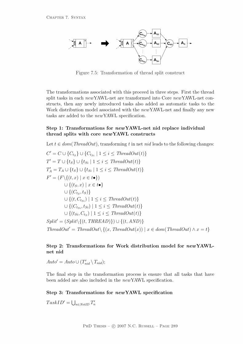
Chapter 7. Syntax
Sn
JOIN
JOIN
#
A A
C
C
C
AS1
A
ASn
S2 ASASC
A
A
A
S1
S2
Figure 7.5: Transformation of thread split construct
The transformations associated with this proceed in three steps. First the threadsplit tasks in each newYAWL-net are transformed into Core newYAWL-net con-structs, then any newly introduced tasks also added as automatic tasks to theWork distribution model associated with the newYAWL-net and finally any newtasks are added to the newYAWL specification.
Step 1: Transformations for newYAWL-net nid replace individualthread splits with core newYAWL constructs
Let t ∈ dom(ThreadOut), transforming t in net nid leads to the following changes:
C ′ = C ∪ {CtS} ∪ {CtSi| 1 ≤ i ≤ ThreadOut(t)}
T ′ = T ∪ {tS} ∪ {tSi | 1 ≤ i ≤ ThreadOut(t)}T ′
A = TA ∪ {tS} ∪ {tSi | 1 ≤ i ≤ ThreadOut(t)}F ′ = (F\{(t, x) | x ∈ t•})
∪ {(tS, x) | x ∈ t•}∪ {(CtS , tS)}∪ {(t, CtSi
) | 1 ≤ i ≤ ThreadOut(t)}∪ {(CtSi
, tSi) | 1 ≤ i ≤ ThreadOut(t)}∪ {(tSi, CtS) | 1 ≤ i ≤ ThreadOut(t)}
Split′ = (Split\{(t,THREAD)}) ∪ {(t,AND)}ThreadOut ′ = ThreadOut\ {(x,ThreadOut(x)) | x ∈ dom(ThreadOut) ∧ x = t}
Step 2: Transformations for Work distribution model for newYAWL-net nid
Auto′ = Auto ∪ (T ′nid \Tnid);
The final step in the transformation process is ensure that all tasks that havebeen added are also included in the newYAWL specification.
Step 3: Transformations for newYAWL specification
TaskID′ =⋃
n∈NetID T ′n
PhD Thesis – c© 2007 N.C. Russell – Page 289

Chapter 7. Syntax
7.2.5 Partial join
The partial join construct has probably the most complex series of transforma-tions associated with it. It is illustrated diagrammatically in Figure 7.6 andessentially involves replacing the partial join construct with the set of all possibleAND-joins that would enable the set of input branches to trigger a join when therequired threshold for the join was reached.
1
1C
2C
1C
2CJO
IN
SP
LIT
JOIN
SP
LIT
SP
LIT
A
X XB2XB1
A
AJ A
A
Z Z
R
RZ
JZ
Z corresponds to one of the combinations of input places
note:
and k =
1
k k
SP
LIT
A
X
m(n )m(n )
C
n−1
Cn
C
n−1
n
o2
T
C
E2nid
2endC
CA,XB1 B1A
C2i
TS2nid
C 2start
C
C
Figure 7.6: Transformation of partial join construct
For example where the partial join had four inputs and two were required forthe join to proceed, then the partial join would be replaced by six two-input AND-joins, each of which is linked to one combination of incoming branches that couldtrigger the join as illustrated by the tasks prefixed AZ
J . As this is a combinatorial
PhD Thesis – c© 2007 N.C. Russell – Page 290

Chapter 7. Syntax
function, there are
(mn
)of these tasks. Similarly, there are the same number
of tasks prefixed AZR which reset the join and allow it to fire again. Only when
one of the AZJ joins has fired can the actual task A be enabled.
A feature of the partial join is the blocking link, which allows specified tasksto serve as gateways into the blocking region for a task. The blocking region is agroup of preceding tasks and their associated branches where only one thread ofexecution should be active on each incoming branch to the partial join for eachtriggering of the join. The block function identifies the set of tasks that constitutethe blocking region for a given task. In Figure 7.6, task X has a blocking linkassociated with it. Once task A has fired, task X is prevented from being enableduntil inputs have been received on all branches to task A and it has reset. Inthe transformed newYAWL-net, each “blocking task” has a place associated withit (e.g. CXB1
). Initially it has a token in it. This is removed when one of thepermutations of input branches allows the (partial) join to fire and only when thepartial join has reset, is the token replaced in the place allowing the “blockingtask” to fire again.
The transformation proceeds in six stages. First, initialization conditions areinserted into any newYAWL-net that contains blocking tasks associated withpartial joins. These conditions allow the blocking tasks to be enabled in a givennet providing the associated partial join has not been enabled.
Step 1: Initial transformation for newYAWL-net nid with partial joins
precondition: ran(Blocknid) 6= ∅C ′ = C ∪ {C2
start, C2end}}
i′ = C2start
o′ = C2end
T ′ = T ∪ {TS2nid, TE2nid
}F ′ = F ∪ {(C2
start, TS2nid), (TS2nid
, i), (o, TE2nid), (TE2nid
, C2end)}
∪ {(TS2nid, CtB1
) | t ∈ dom(Thresh)}∪ {(CtB1
, TE2nid) | t ∈ dom(Thresh)}
Split′ = Split ∪ {(TSnid,AND)}
Join′ = Join ∪ {(TEnid,AND)}
The next step is to transform each of the partial joins in a given net. These need tobe undertaken incrementally (on a task-by-task basis) and involve the insertionof a series of AND-join constructs (AZ
J1...AZJk) such that a distinct AND-join
is added for each combination of incoming paths that could enable the partialjoin. Associated with each AND-join is another AND-join (AZ
R1...AZRk) that allows
the partial join to be reset when execution threads have been received on theremaining incoming branches. There is also a condition (CAB1
) inserted for eachpartial join to ensure that each of the reset tasks (AZ
R1...AZRk) are on a path from
the start to end condition in the newYAWL-net.
PhD Thesis – c© 2007 N.C. Russell – Page 291

Chapter 7. Syntax
Step 2: Transformations for newYAWL-net nid’ (from step 1) to re-place individual partial joins with core newYAWL constructs
Let t ∈ dom(Thresh ′), transforming t in net nid ′ leads to the following changes:
C ′′ = C ′ ∪ {CtB1}
T ′′ = T ′ ∪ {tCJ | C ∈ P(•t) ∧ |C| = Thresh ′(t)}∪ {tDR | D ∈ P(•t) ∧ |D| = | • t| − Thresh ′(t)}
F ′′ = (F ′\{(c, t) | c ∈ •t})∪ {(c, tCJ) | C ∈ P(•t) ∧ |C| = Thresh ′(t) ∧ c ∈ C}∪ {(c, tDR) | D ∈ P(•t) ∧ |D| = | • t| − Thresh ′(t) ∧ c ∈ D}∪ {(tCJ , tDR) | C ∈ P(•t) ∧ |C| = Thresh ′(t) ∧ D = •t \ C}∪ {(tCJ , t) | C ∈ P(•t) ∧ |C| = Thresh ′(t)}∪ {(TS2nid
, CtB1), (CtB1
, TE2nid)}
∪ {(CtB1, tCJ) | C ∈ P(•t) ∧ |C| = Thresh ′(t)}
∪ {(tDR, CtB1) | D ∈ P(•t) ∧ |D| = | • t| − Thresh ′(t)}
Split′′ = Split′ ∪ {(tCJ ,AND) | C ∈ P(•t) ∧ |C| = Thresh ′(t)}∪ {(xDR,AND) | x ∈ dom(Thresh ′) ∩ dom(Block ′) ∧ D ∈ P(•x)
∧ |D| = | • x| − Thresh ′(x) ∧ x = t}Join′′ = (Join′ \ {(t,PJOIN )})
∪ {(t,XOR)}∪ {(tCJ ,AND) | C ∈ P(•t) ∧ |C| = Thresh ′(t)}∪ {(tDR,AND) | D ∈ P(•t) ∧ |D| = | • t| − Thresh ′(t)}
Block ′′ = (Block ′ \ {(x,Block ′(x)) | x ∈ dom(Block ′) ∧ t ∈ Block ′(x)})∪ {(x, (Block ′(x)\{t}) ∪ {tCJ}) | x ∈ dom(Block ′)
∧ t ∈ Block ′(x) ∧ C ∈ P(•t) ∧ |C| = Thresh ′(t)}Rem ′′ = (Rem ′ \ {(x,Rem ′(x)) | x ∈ dom(Rem ′) ∧ t ∈ Rem ′(x)})
∪ {(x,Rem ′(x) ∪ {tCJ} ∪ {tDR}) | C ∈ P(•t) ∧ |C| = Thresh ′(t)
∧ D ∈ P(•t) ∧ |D| = | • t| − Thresh ′(t) ∧ t ∈ Rem ′(x)}Lock ′′ = Lock ′ ∪ {(tCJ ,Lock ′(t)) | C ∈ P(•t) ∧ |C| = Thresh ′(t) ∧ t ∈ dom(Lock)}Pre ′′ = Pre ′ ∪ {(xCJ , P re′(x)) | x ∈ dom(Pre ′) ∧ C ∈ P(•x)
∧ |C| = Thresh ′(x) ∧ x = t}Thresh ′′ = Thresh ′\ {(t,Thresh ′(t))}
The third step is to replace each blocking task with core newYAWL constructs.As each of these tasks may have joins and/or splits associated with them, itis necessary to move these to preceding and subsequent tasks in order to en-sure that they are evaluated separately from the blocking action associated witheach task under consideration. Similarly other constructs associated with eachblocking task (e.g. arc conditions, evaluation sequence of arc conditions, default
PhD Thesis – c© 2007 N.C. Russell – Page 292

Chapter 7. Syntax
arcs etc.) may also need to be migrated and others (e.g. locks, preconditions,postconditions) may need to be replicated.
Step 3: Transformation for newYAWL-net nid” (from step 2) to re-place individual blocking tasks with core newYAWL constructs
Let b ∈ ⋃t∈Tnid′′
Block ′′(t), transforming b in net nid leads to the followingchanges:
C ′′′ = C ′′ ∪ {Cb,xB1| x ∈ dom(Thresh ′′) ∧ b ∈ Block ′′(x)}
T ′′′ = T ′′ ∪ {bB1, bB2}T ′′′
A = T ′′A ∪ {bB1, bB2}
F ′′′ = ((F ′′\ {(c, b) | c ∈ •b})\ {(b, c) | c ∈ b•})∪ {(c, bB1) | c ∈ •b} ∪ {(bB2, c) | c ∈ b•} ∪ {(bB1, b), (b, bB2)}∪ {(Cb,xB1
, xCJ) | x ∈ dom(Block ′′) ∧ b ∈ Block ′′(x)
∧ C ∈ P(•x) ∧ |C| = Thresh ′′(x)}∪ {(xDR, Cb,xB1
) | x ∈ dom(Block ′′) ∧ b ∈ Block ′′(x)
∧ D ∈ P(•x) ∧ |D| = | • x| − Thresh ′′(x)}∪ {(TS2nid
, Cb,xB1) | x ∈ dom(Block ′′) ∧ b ∈ Block ′′(x)}
∪ {(Cb,xB1, TE2nid
) | x ∈ dom(Block ′′) ∧ b ∈ Block ′′(x)}∪ {(Cb,xB1
, b) | x ∈ dom(Block ′′) ∧ b ∈ Block ′′(x)}∪ {(b, Cb,xB1
) | x ∈ dom(Block ′′) ∧ b ∈ Block ′′(x)}Split ′′′ = (Split ′′\{(x, Split ′′(x)) | x ∈ dom(Split ′′) ∧ x = b})
∪ {(xB2, Split ′′(x)) | x ∈ dom(Split ′′) ∧ x = b}∪ {(b,AND)}
Join ′′′ = (Join ′′ \ {(x, Join ′′(x)) | x ∈ dom(Join ′′) ∧ x = b})∪ {(xB1, Join
′′(x)) | x ∈ dom(Join ′′) ∧ x = b}∪ {(b,AND)}
Default ′′′ = (Default ′′ \ {(x,Default ′′(x)) | x ∈ dom(Default ′′) ∧ x = b})∪ {(xB2,Default ′′(x)) | x ∈ dom(Default ′′) ∧ x = b}
<′′′XOR= (<′′
XOR\{(x,<′′xXOR) | x ∈ dom(Split ′′ B {XOR}) ∧ x = b})∪ {(xB2, <
′′xXOR) | x ∈ dom(Split ′′ B {XOR}) ∧ x = b}
Rem ′′′ = ((Rem ′′\{(x,Rem ′′(x)) | x ∈ dom(Rem ′′) ∧ x = b})\ {(x,Rem ′′(x)) | x ∈ dom(Rem ′′) ∧ b ∈ Rem ′′(x)})∪ {(xB2, Rem′′(x)) | x ∈ dom(Rem ′′) ∧ x = b}∪ {(x,Rem ′′(x) ∪ {bB1, bB2}) | x ∈ dom(Rem ′′) ∧ b ∈ Rem ′′(x)}
Comp ′′′ = (Comp ′′\{(x,Comp′′(x)) | x ∈ dom(Comp ′′) ∧ x = b})∪ {(xB2, Comp′′(x)) | x ∈ dom(Comp ′′) ∧ x = b}
Block ′′′ = Block ′′\ {(b, Block′′(b))}
PhD Thesis – c© 2007 N.C. Russell – Page 293
Chapter 7. Syntax
Disable ′′′ = (Disable ′′\{(x,Disable ′′(x)) | x ∈ dom(Disable ′′) ∧ x = b})∪ {(xB2,Disable ′′(x)) | x ∈ dom(Disable ′′) ∧ x = b}
Lock ′′′ = Lock ′′ ∪ {(xB1,Lock ′′(x)) | x ∈ dom(Lock ′′) ∧ x = b}∪ {(xB2,Lock ′′(x)) | x ∈ dom(Lock ′′) ∧ x = b}
ArcCond ′′′ = (ArcCond ′′ \ {((x, c), cond1 ) | x ∈ dom(Split ′′ B {OR,XOR})∧ ((x, c), cond1 ) ∈ ArcCond ′′ ∧ c ∈ x • ∧x = b})
∪ {((bB2, c), cond1 ) | x ∈ dom(Split ′′ B {OR,XOR})∧ ((x, c), cond1 ) ∈ ArcCond ′′ ∧ c ∈ x • ∧x = b})
Pre ′′′ = Pre ′′ ∪ {(xB1,Pre ′′(x)) | x ∈ dom(Pre ′′) ∧ x = b}Post ′′′ = Post ′′ ∪ {(xB2,Post ′′(x)) | x ∈ dom(Post ′′) ∧ x = b}
The fourth step is to replicate any parameters passed to each blocking task to the(inserted) task preceding and following the blocking task. This is necessary asthe preceding task may have associated preconditions or locks and the followingtask may have splits, postconditions or locks which rely on data elements passedto the blocking task in order to be evaluated.
Step 4: Transformations for Data passing model for newYAWL-net nid
Let t ∈ Tnid, transforming t in net nid leads to the following changes:
InPar ′ = InPar ∪ {((tB1, v), e) | x ∈ dom(Block)
∧ t ∈ (dom(Pre) ∪ dom(Lock)) ∩ Block(x)
∧ ((t, v), e) ∈ InPar}∪ {((tB2, v), e) | x ∈ dom(Block)
∧ t ∈ (dom(Split B {OR,XOR}) ∪ dom(Post)
∪ dom(Lock)) ∩ Block(x)
∧ ((t, v), e) ∈ InPar}∪ {((xCJ , v), e) | x ∈ dom(Thresh) ∧ C ∈ P(•x)
∧ |C| = Thresh(x) ∧ ((x, v), e) ∈ InPar ∧ x = t}OptInPar ′ = OptInPar ∪ {(tB1, v) | x ∈ dom(Block)
∧ t ∈ (dom(Pre) ∪ dom(Lock)) ∩ Block(x)
∧ (t, v) ∈ OptInPar}∪ {(tB2, v) | x ∈ dom(Block)
∧ t ∈ (dom(Split B {OR,XOR}) ∪ dom(Post)
∪ dom(Lock)) ∩ Block(x)
∧ (t, v) ∈ OptInPar}∪ {(xCJ , v) | x ∈ dom(Thresh) ∧ C ∈ P(•x)
∧ |C| = Thresh(x) ∧ (x, v) ∈ OptInPar ∧ x = t}
The fifth step is to transform the Work distribution model associated with thenewYAWL-net in order to ensure all added tasks are automatic (i.e. do not needto be distributed to resources for execution).
PhD Thesis – c© 2007 N.C. Russell – Page 294

Chapter 7. Syntax
Step 5: Transformations for Work distribution model for newYAWL-net nid
Auto ′ = Auto ∪ (T ′′′ \T );
The final step in the transformation process is ensure that all tasks that havebeen added are also included to the newYAWL specification.
Step 6: Transformations for newYAWL specification
TaskID ′ =⋃
n∈NetID T ′′′n
STmap ′ = ((STmap\ {(s, STmap(s)) | s ∈ dom(STmap)
∧ STmap(s) ∩ dom(Thresh) 6= ∅})\ {(s, STmap(s)) | s ∈ dom(STmap)
∧ x ∈ dom(Block)
∧ STmap(s) ∩ Block(x) 6= ∅})∪ {(s, STmap(s) ∪ {tCJ}) | s ∈ dom(STmap)
∧ t ∈ STmap(s) ∩ dom(Thresh)
∧ C ∈ P(•t) ∧ |C| = Thresh(t)}∪ {(s, STmap(s) ∪ {tB1, tB2}) | s ∈ dom(STmap)
∧ x ∈ dom(Block)
∧ STmap(s) ∩ Block(x) 6= ∅}
7.2.6 Tasks directly linked to tasks
newYAWL supports the direct linkage of one task to another in a process model.However, during execution, it is necessary that the state of a process instancecan be completely captured. For this reason, an implicit condition is insertedbetween directly connected tasks, reflecting the Petri net foundations on whichnewYAWL is based. Figure 7.7 illustrates this transformation.
BA B A CAB
Figure 7.7: Inserting an implicit condition between directly linked tasks
This transformation only applies to elements of a newYAWL-net as described inDefinition 2. There are no changes to the other models.
Transformations for newYAWL-net nid to insert conditions betweendirectly linked tasks
C ′ = C ∪ {Ct1,t2 | (t1, t2) ∈ F ∩ (T × T )}
PhD Thesis – c© 2007 N.C. Russell – Page 295
Chapter 7. Syntax
F ′ = (F\(T × T ))
∪ {(t1, Ct1t2) | (t1, t2) ∈ F ∩ (T × T )}∪ {(Ct1t2 , t2) | (t1, t2) ∈ F ∩ (T × T )}
Rem ′ = (Rem\{(t,Rem(t)) | (t1, t2) ∈ F ∩ (T × T ) ∧ t ∈ dom(Rem)
∧ {t1, t2} ⊆ Rem(t)})∪ {(t,Rem(t) ∪ {Ct1,t2}) | (t1, t2) ∈ F ∩ (T × T ) ∧ t ∈ dom(Rem)
∧ {t1, t2} ⊆ Rem(t)}ArcCond ′ = (ArcCond \ {((t1, t2), cond1) | ((t1, t2), cond1) ∈ ArcCond
∧ (t1, t2) ∈ F ∩ (T × T )})∪ {((t1, Ct1t2), cond1) | ((t1, t2), cond1) ∈ ArcCond
∧ (t1, t2) ∈ F ∩ (T × T )}Default ′ = (Default \ {(t1,Default(t1)) | t1 ∈ dom(Default)
∧ (t1,Default(t1)) ∈ F ∩ (T × T )})∪ {(t1, Ct1t2) | t1 ∈ dom(Default)
∧ (t1,Default(t1)) ∈ F ∩ (T × T )})<′tXOR={(t, (<t
XOR ∩ (C × C))
∪ {(x,Ct,t′) | t′ ∈ T ∩ t • ∧x ∈ C ∧ (x, t′) ∈<tXOR}
∪ {(Ct,t′ , x) | t′ ∈ T ∩ t • ∧x ∈ C ∧ (t′, x) ∈<tXOR}
∪ {(Ct,t′ , Ct,t′′) | t′ ∈ T ∩ t • ∧t′′ ∈ T ∩ t • ∧(t′, t′′) ∈<tXOR})
| t ∈ dom(Split) ∧ Split(t) = XOR}
7.3 Semantic model initialization
This section presents a series of marking functions which describe how a corenewYAWL specification can be transformed into an initial marking of the new -YAWL semantic model. The act of doing this prepares a newYAWL specificationfor enactment. Moreover, because the newYAWL semantic model is formalizedusing CP-nets, once the resultant initial marking is applied to the semantic modelin the CPN Tools environment, it is possible to directly execute the newYAWLspecification. The marking functions presented below operate between a corenewYAWL specification and the semantic model presented in Chapter 8. Theyassume the existence of the auxiliary functions described subsequently.
7.3.1 Auxiliary functions
In order to describe the various transformations more succinctly, we first presenteleven auxiliary functions. Throughout this section the designated value procid isassumed to be the identifier for the newYAWL specification under consideration.
FUN (fn(p1, p2, ...pn)) = fn where fn(p1, p2, ...pn) is a function definition. FUNreturns the name of the function;
VARS(fn(p1, p2, ...pn)) = {p1, p2, ...pn}. VARS returns the set of data elementsin the function definition;
PhD Thesis – c© 2007 N.C. Russell – Page 296
Chapter 7. Syntax
VAR(fn(p1)) = p1 where p1 is of type RecExpr, i.e. p1 is a record-based formalparameter containing a single data element in a tabular format for use with amultiple instance task. VAR returns the record-based data element;
LCONDS takes a task and returns a sequence of the link condition tuples for theoutgoing arcs associated with the task, together with the set of variables and thecondition used to evaluate whether the arc should be selected43. For XOR-splits,the sequence defines the order in which the arc conditions should be evaluatedin order to determine the arc that will be enabled. The order is immaterial forOR-splits as several arcs can potentially be enabled.
LCONDS(t) ={[(ArcCond(t, c),VARS(ArcCond(t, c)), c) | c ← [t•]<t
XOR ] if Split(t) = XOR[(ArcCond(t, c),VARS(ArcCond(t, c)), c) | c ← [t•]] if Split(t) = OR
CAPVALS(u) = [{(c, v) | UserQual(u, c) = v}], i.e. CAPVALS returns a list ofthe capability-value tuples corresponding to a nominated user u. The ordering ofthese tuples is arbitrary;
VDEF takes a variable v of type VarID and returns the static definition for thevariable in the form used in the semantic model;
VDEF(v) =
< gdef:(procid ,VName(v)) > if v ∈ VarIDGlobal
< bdef:(procid ,VFmap(v),VName(v)) > if v ∈ VarIDFolder
< cdef:(procid ,VName(v)) > if v ∈ VarIDCase
< bdef:(procid ,VBmap(v),VName(v)) > if v ∈ VarIDBlock
< sdef:(procid ,VSmap(v),VName(v)) > if v ∈ VarIDScope
< tdef:(procid ,VTmap(v),VName(v)) > if v ∈ VarIDTask
< mdef:(procid ,VMmap(v),VName(v)) > if v ∈ VarIDMI
PUSAGE identifies whether parameter p is a mandatory or optional parameterin the context of task t;
PUSAGE(x, p) =
′′opt′′ if ((x, p) ∈ (dom(OptInPar) ∪ dom(OptOutPar)∪ dom(OptInNet) ∪ dom(OptOutNet))
∨ (x =′′ null′′ ∧ p ∈ dom(OptInProc)∪ dom(OptOutProc))
′′mand′′ otherwise
MT YPE identifies whether task t is a singular or multiple-instance task;
MT YPE(t) =
{ ′′multiple′′ if t ∈ dom(Nofi)′′singular′′ otherwise
PREC returns true if task x precedes task t (i.e. there is a path from x to t);
PREC(x, t) = (x, t) ∈ F ∗, where F ∗ is the reflexive transitive closure of the flowrelation F ;
43Details of the sequence comprehension notation used in this expression can be found inAppendix A.
PhD Thesis – c© 2007 N.C. Russell – Page 297

Chapter 7. Syntax
The following three functions support the transformation of a newYAWL-net toa corresponding reset net that allows the enablement of an OR-join construct tobe determined based on Wynn et al.’s algorithm [WEAH05]. These functions arebased on the transformations illustrated in Figure 7.3.1.
Figure 7.8: Reset net transformations for newYAWL constructs(from [WEAH05])
RNILS(tOR) returns the set of input arcs to tasks in the reset net correspondingto the newYAWL-net of which the OR-join tOR is a member. Only the tasks whichprecede tOR are included in this set.
RNILS(tOR) ={(x, tS) | t /∈ dom(Join) ∪ dom(Split) ∧ x ∈ •t ∧ PREC(t, tOR)}∪{(pt, tE) | t ∈ T∧t ∈ T∧t /∈ dom(Join)∪dom(Split)∧x ∈ •t∧PREC(t, tOR)}∪ {(x, tS) | t ∈ T ∧ Join(t) = AND ∧ x ∈ •t ∧ PREC(t, tOR)}∪ {(pt, tE) | t ∈ T ∧ Split(t) = AND ∧ PREC(t, tOR)}∪ {(x, txS) | t ∈ T ∧ Join(t) = XOR ∧ x ∈ •t ∧ PREC(t, tOR)}∪ {(pt, t
xE) | t ∈ T ∧ Split(t) = XOR ∧ x ∈ t • ∧PREC(t, tOR)}
∪ {(pt, txE) | t ∈ T ∧ Split(t) = OR ∧ x ∈ P+(t•) ∧ PREC(t, tOR)}
RNOLS(tOR) returns the set of output arcs to tasks in the reset net correspond-ing to the newYAWL-net of which the OR-join tOR is a member. Only the taskswhich precede tOR are included in this set.
RNOLS(tOR) ={(tS, pt) | t ∈ T ∧ t /∈ dom(Join) ∧ t /∈ dom(Split) ∧ PREC(t, tOR)}∪ {(tE, x) | t ∈ T ∧ t /∈ dom(Join)∧ t /∈ dom(Split)∧ x ∈ t • ∧PREC(t, tOR)}∪ {(tS, pt) | t ∈ T ∧ Join(t) = AND ∧ PREC(t, tOR)}∪ {(tE, x) | t ∈ T ∧ Split(t) = AND ∧ x ∈ t • ∧PREC(t, tOR)}∪ {(txS, pt) | t ∈ T ∧ Join(t) = XOR ∧ x ∈ •t ∧ PREC(t, tOR)}∪ {(txE, x) | t ∈ T ∧ Split(t) = XOR ∧ x ∈ t • ∧PREC(t, tOR)}∪ {(txE, y) | t ∈ T ∧ Split(t) = OR ∧ x ∈ P+(t•) ∧ y ∈ x ∧ PREC(t, tOR)}
PhD Thesis – c© 2007 N.C. Russell – Page 298

Chapter 7. Syntax
RNRLS(tOR) returns the set of reset arcs to tasks in the reset net correspondingto the newYAWL-net of which the OR-join tOR is a member. Only the tasks whichprecede tOR are included in this set.
RNRLS(tOR) ={(tE, x) | t ∈ T ∧ t /∈ dom(Split) ∧ PREC(t, tOR)
∧ x ∈ {{pt′ | t′ ∈ Rem(t) ∩ T ∧ PREC(t′, tOR)}∪ {c | c ∈ Rem(t) ∩ C ∧ PREC(c, tOR)}}}
{(tE, x) | t ∈ T ∧ Split(t) = AND ∧ PREC(t, tOR)∧ x ∈ {{pt′ | t′ ∈ Rem(t) ∩ T ∧ PREC(t′, tOR)}
∪ {c | c ∈ Rem(t) ∩ C ∧ PREC(c, tOR)}}}{(tpE, x) | t ∈ T ∧ Split(t) = XOR ∧ p ∈ t • ∧PREC(t, tOR)
∧ x ∈ {{pt′ | t′ ∈ Rem(t) ∩ T ∧ PREC(t′, tOR)}∪ {c | c ∈ Rem(t) ∩ C ∧ PREC(c, tOR)}}}
{(tyE, x) | t ∈ T ∧ Split(t) = OR ∧ y ∈ P+(t•) ∧ PREC(t, tOR)∧ x ∈ {{pt′ | t′ ∈ Rem(t) ∩ T ∧ PREC(t′, tOR)}
∪ {c | c ∈ Rem(t) ∩ C ∧ PREC(c, tOR)}}}RNCS(tOR) returns the set of conditions in the reset net corresponding to thenewYAWL-net of which the OR-join tOR is a member. Only the conditions whichprecede tOR are included in this set.
RNCS(tOR) = dom(RNILS (tOR)) ∪ ran(RNOLS (tOR));
7.3.2 newYAWL marking functions
This section presents a series of marking functions which describe how a corenewYAWL specification can be transformed into an initial marking of the new -YAWL semantic model. They assume the existence of the auxiliary functionsdescribed above. The population of a place in the CPN Tools environment isassumed to be a multiset however, for the purposes of these transformations,there is no requirement for multiplicity. As part of these transformations, itis assumed that a mechanism exists for mapping conditions that exist within acore newYAWL specification to corresponding ML functions that describe theirevaluation in the CPN Tools environment.
The process state place records the newYAWL conditions in which tokens arepresent within a newYAWL specification. Initially this place is empty as thereare no tokens yet.
pop(process state) = ∅
The folder mappings place records the correspondences between the folder namesused when defining variable usage in a process definition and the actual folderIDs assigned to a process instance at initiation. Initially it is empty as thecorrespondences are recorded when a process instance is initiated.
pop(folder mappings) = ∅
The scope mappings place identifies the tasks which correspond to a given scope.It is populated from the STmap function in the abstract syntax model.
PhD Thesis – c© 2007 N.C. Russell – Page 299

Chapter 7. Syntax
pop(scope mappings) = {< procid , s, STmap(s) > | s ∈ ScopeID}inlinks and outlinks records the incoming and outgoing arcs for tasks in the flowrelation. They are initially populated from the function F in the abstract syntaxmodel;
inlinks = {< procid , c, t > | (c, t) ∈ F ∧ c ∈ C ∧ t ∈ T}outlinks = {< procid , t, c > | (t, c) ∈ F ∧ c ∈ C ∧ t ∈ T}The flow relation place is the aggregation of inlinks and outlinks.
pop(flow relation) = inlinks ∪ outlinks
The variable instances place holds the values of variables instantiated during theexecution of a process instance. Initially it is empty.
pop(variable instances) = ∅
The variable declarations place holds the static definitions of variables used duringexecution of the process. It is populated using the VDEF function along withdata from the PushAllowed and PullAllowed attributes and the DType functionsin the abstract syntax model.
Let V arTX = {< VDEF(v), v ∈ PushAllowed , v ∈ PullAllowed ,DType(v) >| v ∈ VarIDX}
pop(variable declarations) = {< VarTGlobal ,VarTFolder ,VarTCase ,VarTBlock ,VarT Scope ,VarTTask ,VarTMI >}
The lock register place holds details of variables that have been locked by a specifictask instance during execution. Initially it is empty as no variables exist.
pop(lock register) = ∅;
The process hierarchy place identifies the correspondences between compositetasks and their corresponding newYAWL-net decompositions. It is initially pop-ulated from Tn and the TNmap and STmap functions in the abstract syntaxmodel.
Let Scopes(nid) = {s ∈ ScopeID | ∃t∈STmap(s)[t ∈ Tnid]}pop(process hierarchy) = {< procid , t, in, on, Tn, Scopes(n) >
| t ∈ dom(TNmap) ∧ n = TNmap(t)}tinpars, toutpars, binpars, boutpars, miinpars, mioutpars, pinpars, poutpars iden-tify the input and output parameter mappings for task, block, multiple instanceand process constructs respectively. They are populated from the InPar, Out-Par, InNet, OutNet, MIInPar, MIOutPar, InProc and OutProc functions in theabstract syntax model.
tinpars = {< procid , t,VARS(e),FUN (e), {v},′′ invar′′,PUSAGE(t, v),MT YPE(t) > | (t, v, e) ∈ InPar}
toutpars = {< procid , t,VARS(e),FUN (e), {v},′′ outvar′′,PUSAGE(t, v),MT YPE(t) > | (t, v, e) ∈ OutPar}
PhD Thesis – c© 2007 N.C. Russell – Page 300

Chapter 7. Syntax
binpars = {< procid , n,VARS(e),FUN (e), {v},′′ invar′′,PUSAGE(n, v),MT YPE(n) > | (n, v, e) ∈ InNet}
boutpars = {< procid , n,VARS(e),FUN (e), {v},′′ outvar′′,PUSAGE(n, v),MT YPE(n) > | (n, v, e) ∈ OutNet}
miinpars = {< procid , t,VAR(e),FUN (e), v,′′ invar′′,′′ mand′′,MT YPE(t) >| (t, v, e) ∈ MIInPar}
mioutpars = {< procid , t,VAR(e),FUN (e), v,′′ outvar′′,′′ mand′′,MT YPE(t) >| (t, v, e) ∈ MIOutPar}
pinpars = {< procid ,′′ null′′,VARS(e),FUN (e), {v},′′ invar′′,PUSAGE(′′null′′, v),′′singular′′ > | (v, e) ∈ InProc}
poutpars = {< procid ,′′ null′′,VARS(e),FUN (e), {v},′′ outvar′′,PUSAGE(′′null′′, v),′′ singular′′ > | (v, e) ∈ OutProc >}
The parameter mappings place is populated from the aggregation of tinpars, tout-pars, binpars, boutpars,miinpars, mioutpars, pinpars and poutpars.
pop(parameter mappings) = tinpars ∪ toutpars ∪ binpars ∪ boutpars∪miinpars ∪mioutpars ∪ pinpars ∪ poutpars
The mi a place holds work items that are currently active. It is initially empty.
pop(mi a) = ∅;
The mi e place holds work items that have been enabled but not yet started. Itis initially empty as no work items are active in any process instances.
pop(mi e) = ∅;
The exec place holds work items that are currently being executed. It is initiallyempty.
pop(exec) = ∅;
The mi c place holds work items that have been completed but have not yetexited (and triggered subsequent tasks). It is initially empty.
pop(mi c) = ∅;
atask, ctask, mitask and cmitask record details of atomic, composite, multiple-instance and composite multiple-instance tasks respectively that determine howthey will be dealt with at runtime. They are populated from the T and M setsand the TNmap function in the abstract syntax model.
atasks = {< atask:(procid , t) > | t ∈ TA\M};ctasks = {< ctask:(procid , t,TNmap(t)) > | t ∈ TC\M};mitasks = {< mitask:(procid , t,min,max , th, sd , canc) >
| t ∈ M\TA ∧ Nofi(t) = (t,min,max , th, sd , canc)};cmitasks = {< cmitask:(procid , t,TNmap(t),min,max , th, sd , canc) >
| t ∈ M ∩ TC ∧ Nofi(t) = (t,min,max , th, sd , canc)}The task details place is populated from the aggregation of atask, ctask, mitaskand cmitask.
PhD Thesis – c© 2007 N.C. Russell – Page 301

Chapter 7. Syntax
pop(task details) = atasks ∪ ctasks ∪mitasks ∪ cmitasks;
The active nets place identifies the particular newYAWL-nets that are active (i.e.have a thread of execution running in them). Initially it is empty as no processinstances (and hence no particular nets) are active.
pop(active nets) = ∅;
The preconditions place identifies task and process preconditions that must besatisfied in order for a task instance or process instance to proceed. It is populatedfrom the Pre and WPre functions in the abstract syntax model.
pop(preconditions) = {< procid , t,FUN (Pre(t)),VARS(Pre(t)) >| t ∈ dom(Pre) >}
∪ {< procid ,′′ null′′,FUN (WPre),VARS(WPre) >};The postconditions place identifies task and process postconditions that must besatisfied in order for a task instance or process instance to complete execution. Itis populated from the Post and WPost functions in the abstract syntax model.
pop(postconditions) = {< procid , t,FUN (Post(t)),VARS(Post(t)) >| t ∈ dom(Post) >}
∪ {< procid ,′′ null′′,FUN (WPost),VARS(WPost) >};The assign wi to resource place holds work items that have been enabled butneed to be distributed to users who can undertake them. Initially it is empty.
pop(assign wi to resource) = ∅;
The wi started by resource place holds work items that have been started by auser but not yet completed. Initially it is empty.
pop(wi started by resource) = ∅;
The wi completed by resource place holds work items that have been completedby a user but have not had their status changed to completed from a control-flowperspective. Initially it is empty.
pop(wi completed by resource) = ∅;
The wi to be cancelled place holds work items that are in the process of beingdistributed to users but now need to be cancelled. Initially it is empty.
pop(wi to be cancelled) = ∅;
asplits, osplits and xsplits identify AND, OR and XOR splits in a newYAWL-net. For OR and XOR splits details of the outgoing link conditions and defaultlink conditions are captured as part of this definition. They are populated fromthe Split and Default functions in the abstract syntax model and the LCONDScondition.
asplits = {< asplit : (procid , t) > | Split(t) = AND}osplits = {< osplit : (procid , t,LCONDS(t),Default(t)) > | Split(t) = OR}xsplits = {< xsplit : (procid , t,LCONDS(t)),Default(t)) > | Split(t) = XOR}
PhD Thesis – c© 2007 N.C. Russell – Page 302

Chapter 7. Syntax
The splits place is populated from the aggregation of asplits, osplits and xsplits.
pop(splits) = asplits ∪ osplits ∪ xsplits;
ajoin, ojoin and xjoin identify AND, OR and XOR joins in a newYAWL-net. Inthe case of an OR-join, the details of the reset net which can be used to determinewhen the OR-join can be enabled is also recorded. They are populated from theJoin function and in the case of the OR join, also utilize the RNILS, RNOLS,RNRLS and RNCS functions to determine the incoming, outgoing and resetlinks and the set of conditions associated with the corresponding reset net.
ajoins = {< ajoin : (procid , t) > | Join(t) = AND}ojoins = {< ojoin : (procid , t,RNILS(t),RNOLS(t),RNRLS(t),
RNCS(t)) >| Join(t) = OR}xjoins = {< xjoin : (procid , t) > | Join(t) = XOR}The joins place is populated from the aggregation of ajoins, ojoins and xjoins.
pop(joins) = ajoins ∪ ojoins ∪ xjoins;
The task instance count place records the number of instances of each task thathave executed for a process. Initially it is empty.
pop(task instance count) = ∅;
The required locks place identifies the locks on specific variables that are requiredfor a task before an instance of it can be enabled. The place is populated fromthe Lock function.
pop(required locks) = {< procid , t,VDEF(v) >| v ∈ Lock(t)};The cancel set place identifies tasks instances that should be cancelled or force-completed when an instance on a nominated task in the same process instancecompletes. The place is populated from the Rem and Comp functions.
pop(cancel set) = {< procid , t,Rem(t) ∩ C,Rem(t) ∩ T,Comp(t) >| t ∈ dom(Rem) ∩ dom(Comp)}
∪ {< procid , t,Rem(t) ∩ C,Rem(t) ∩ T,∅ >| t ∈ dom(Rem)\dom(Comp)}
∪ {< procid , t,∅,∅, dom(Comp) >| t ∈ dom(Comp)\dom(Rem)}
The disable set place identifies multiple tasks instances that should be disabledfrom being able to create further dynamic instances “on the fly” when an in-stance on a nominated task in the same process instance completes. The place ispopulated from the Disable function.
pop(disable set) = {< procid , t,Disable(t) > | t ∈ dom(Disable)}The chained execution users place identifies which users are currently operatingin chained execution mode. Initially it is empty.
pop(chained execution users) = ∅;
PhD Thesis – c© 2007 N.C. Russell – Page 303
Chapter 7. Syntax
The piled execution users place identifies which users are currently operating inpiled execution mode. Initially it is empty.
pop(piled execution users) = ∅;
The distributed work items place identifies work items that can be distributed tousers. Each work item has had its routing determined, but the work items havenot yet been distributed to specific users. Initially it is empty.
pop(distributed work items) = ∅;
The task distribution details place identifies the routing strategy to be used fordistributing work items corresponding to a given task. It is populated from theDistUser, DistRole, DistVar and Initiator functions.
pop(task distribution details) ={< procid , t, users:DistUser(t), o, a, s >
| t ∈ dom(DistUser) ∧ (o, a, s) = Initiator(t)}∪ {< procid , t, roles:DistRole(t), o, a, s >
| t ∈ dom(DistRole) ∧ (o, a, s) = Initiator(t)}∪ {< procid , t, vars:DistVar(t), o, a, s >
| t ∈ dom(DistVar) ∧ (o, a, s) = Initiator(t)}∪ {< procid , t,AUTO ,′′ system′′,′′ system′′,′′ system′′ > | t ∈ Auto}
The offered work items place identifies work items that have been offered to users.Initially it is empty as there are no work items.
pop(offered work items) = ∅;
The allocated work items place identifies work items that have been allocated tousers. Initially it is empty as there are no work items.
pop(allocated work items) = ∅;
The started work items place identifies work items that have been started byusers. Initially it is empty as there are no work items.
pop(started work items) = ∅;
The allocation requested place identifies work items that users have requested tohave allocated to them. Initially it is empty as there are no work items.
pop(allocation requested) = ∅;
The in progress place identifies work items that users are currently executing.Initially it is empty as there are no work items.
pop(in progress) = ∅;
The logged on users place identifies users that have logged on. Initially it is emptyas no users are logged on.
pop(logged on users) = ∅;
PhD Thesis – c© 2007 N.C. Russell – Page 304

Chapter 7. Syntax
The logged off users place identifies users who are not currently logged on (andhence cannot execute work items). Initially all users are deemed to be logged off.
pop(logged off users) = UserID ;
The task user selection basis identifies a user routing strategy for specific taskswhere they must be distributed to precisely one user. The place is populatedfrom the UserSel function.
pop(task user selection basis) = {< procid , t,UserSel(s) > | t ∈ dom(UserSel)}The users place identifies the users to whom work may be distributed. It ispopulated from the UserID type.
pop(users) = UserID ;
The user role mappings place identifies the users that correspond to each role. Itis populated from the RoleUser function.
pop(user role mappings) = {< r,RoleUser(r) > | r ∈ RoleID};The four eyes constraints place identifies task pairs within a process instancethat cannot be executed by the same user. It is populated from the FourEyesfunction.
pop(four eyes constraints) = {< procid , t,FourEyes(t) > | t ∈ dom(FourEyes)}The retain familiar constraints place identifies task pairs within a process instancethat must be executed by the same user. It is populated from the SameUserfunction.
pop(retain familiar constraints) = {< procid , t, SameUser(t) >| t ∈ dom(SameUser)}
The org group mappings place identifies the type and parent group (if any) foreach organizational group. It is populated from the GroupType and OrgStructfunctions.
pop(org group mappings) ={< og,GroupType(og),OrgStruct(og) >
| og ∈ OrgGroupID ∩ dom(OrgStruct)}∪ {< og,GroupType(og),′′ null′′ >
| og ∈ OrgGroupID\dom(OrgStruct)}The user job mappings place identifies the jobs that a given user possesses. It ispopulated from the UserJob function.
pop(user job mappings) = {< u, j > | u ∈ UserID ∧ j ∈ UserJob(u)}The org job mappings place identifies the organizational group and superior job (ifany) for a given job. It is populated from the JobGroup and Superior functions.
pop(org job mappings) = {< j, JobGroup(j ), Superior(j ) > | j ∈ dom(Superior)}∪ {< j, JobGroup(j ),′′ null′′ > | j ∈ JobID\dom(Superior)}
PhD Thesis – c© 2007 N.C. Russell – Page 305

Chapter 7. Syntax
The work item event log place holds a list of significant work item events. Initiallyit is empty.
pop(work item event log) = ∅;
The organizational task distributions place holds details of tasks that are to bedistributed using an organizational distribution function. It is populated fromthe OrgDist function.
pop(organizational task distributions) ={< procid , t,FUN (OrgDist(t)) > | t ∈ dom(OrgDist)}
The historical task distributions place holds details of tasks that are to be dis-tributed using a historical distribution function. It is populated from the HistDistfunction.
pop(historical task distributions) ={< procid , t,FUN (HistDist(t)) > | t ∈ dom(HistDist)}
The capability task distributions place holds details of tasks that are to be dis-tributed using a capability-based distribution function. It is populated from theCapDist function.
pop(capability task distributions) ={< procid , t,FUN (CapDist(t)) > | t ∈ dom(CapDist)}
The user capabilities place identifies capabilities and their associated values thatindividual users possess. It is populated using the CAPVALS function.
pop(user capabilities) = {< u, CAPVALS(u) > | u ∈ UserID}The failed work items place identifies work items that could not be routed to anyuser. Initially it is empty.
pop(failed work items) = ∅;
The user privileges place identifies the privileges associated with each user. It ispopulated from the UserPriv function.
pop(user privileges) = {< u,UserPriv(u) > | u ∈ dom(UserPriv)}The user task privileges place identifies the privileges associated with each userin relation to a specific task. It is populated from the UserTaskPriv function.
pop(user task privileges) = {< u, t,UserTaskPriv(u, t) >| (u, t) ∈ dom(UserTaskPriv)}
The requested place holds the identity work items identified for being upgradedor downgraded in a user’s work list. Initially it is empty.
pop(requested) = ∅;
The work list view place provides a list of the work items currently in a nominateduser’s work list. Initially it is empty.
PhD Thesis – c© 2007 N.C. Russell – Page 306

Chapter 7. Syntax
pop(work list view) = ∅;
The new offerees place identifies an alternate set of users to whom a work itemmay be offered. Initially it is empty.
pop(new offerees) = ∅;
7.4 Summary
This chapter has defined an abstract syntax for newYAWL. It provides completecoverage of the control-flow, data and resource perspectives and contains sufficientdetail for a business process model captured using it to be directly enacted.This chapter also describes the process associated with preparing a newYAWLspecification for enactment. This occurs in two stages: first a complete newYAWLspecification is simplified using a series of transformations, then this simplified(or core) specification is mapped to an initial marking of the newYAWL semanticmodel. The next chapter describes the newYAWL semantic model, which isdefined in the form of a CP-net, in detail and defines the manner in which anewYAWL business process is actually enacted.
PhD Thesis – c© 2007 N.C. Russell – Page 307

Chapter 8. Semantics
Chapter 8
Semantics
The preceding chapters have laid the groundwork for newYAWL describing itsobjectives, proposing a new set of suitable language primitives that enable thebroadest range of the patterns to be supported, detailing an abstract syntax modeland describing how a candidate process model captured using the abstract syntaxcan be mapped into an initial marking of the semantic model thus allowing it to bedirectly executed. This chapter presents the semantic model for newYAWL, usinga formalization based on CP-nets44. This model has been developed using CPNTools and hence offers the dual benefits of both providing a detailed definitionof the operation of newYAWL and also supporting the direct execution of aprocess model that is captured in this format. This provides an excellent basisfor investigating and validating the operation of individual language elements aswell as confirming they can be coalesced into a common execution environmentand effectively integrated. Furthermore, such a model provides an extremelyeffective platform for reasoning about the operation of specific constructs as wellas investigating potential execution scenarios in real-world newYAWL models.
This chapter is organized in four parts. First an overview of the semanticmodel is presented. Then the core operational concepts underpinning the modelare introduced. The third section describes the manner in which the control-flowand data perspectives are operationalized. Finally the fourth section presents thework distribution facilities in newYAWL.
8.1 Overview
The CP-net model for newYAWL logically divides into two main parts: (1) thecontrol-flow and data sections and (2) the work distribution, organizational modeland resource management sections. These roughly correspond to definitions 1 and2 and definitions 3, 4 and 5 of the abstract syntax model respectively, which inturn seek to capture the majority of control-flow and data patterns and the re-source patterns. Figure 8.1, which is the topmost CP-net diagram in the semanticmodel, provides a useful summary of the major components and their interrela-tionship. The various aspects of control-flow, data management and work distri-
44Note that the CP-net model for newYAWL including all ML code is available from thenewYAWL website: see http://www.yawl-system.com/newYAWL for more details.
PhD Thesis – c© 2007 N.C. Russell – Page 308

Chapter 8. Semantics
bution are encoded into the CP-net model as tokens in individual places. Thetoplevel view of the lifecycle of a process instance is indicated by the transitionsin this diagram connected by the thick black line. First a new process instance isstarted, then there are a succession of enter→start→complete→exit transi-tions which fire as individual task instances are enabled, the work items associatedwith them are started and completed and the task instances are finalized beforetriggering subsequent tasks in the process model. Each atomic work item needsto be distributed to a suitable resource for execution, an act which occurs via thework distribution transition. This cycle repeats until the last task instancein the process is completed. At this point, the process instance is terminatedvia the end case transition. There is provision for data interchange betweenthe process instance and the environment via the data management transition.Finally where a process model supports task concurrency via multiple work iteminstances, there is provision for the dynamic addition of work items via the add
transition.
The major data items shared between the activities which facilitate the processexecution lifecycle are shown as shared places in this diagram. Not surprisingly,this includes both static elements which describe characteristics of individualprocesses such as the flow relation, task details, variable declarations, parametermappings, preconditions, postconditions, scope mappings and the hierarchy ofprocesses and subprocesses which make up an overall process model, all of whichremain unchanged during the execution of particular instances of the process. Italso includes dynamic elements which describe how an individual process instanceis being enacted at any given time. These elements are commonly known asthe state of a process instance and include items such as the current markingof the place in the flow relation, variable instances and their associated values,locks which restrict concurrent access to data elements, details of subprocessescurrently being enacted, folder mappings (identifying shared data folders assignedto a process instance) and the current execution state of individual work items(e.g. enabled, started or completed).
There is relatively tight coupling between the places and transitions in Fig-ure 8.1, illustrating the close integration that is necessary between the variousaspects of the control-flow and data perspectives in order to enact a processmodel. The coupling between these places and the work distribution transi-tion however is more sparse. There are no static aspects of the process that areshared with other transitions in the model and other than the places which serveto communicate work items being distributed to resources for execution (and be-ing started, completed or cancelled), the variable instances place is the onlyaspect of dynamic data that is shared with the work distribution subprocess.
All of these transitions in Figure 8.1 are substitution transitions (as illustratedby the double borders) for significantly more complex subprocesses that we willdiscuss in further detail in subsequent sections. These discussions will seek toboth describe how the various language primitives in the newYAWL syntax areimplemented as well as more generally explaining how the various patterns in thecontrol-flow, data and resource perspectives are realized.
PhD Thesis – c© 2007 N.C. Russell – Page 309

Chapter 8. Semantics
�������
��������
��� ��������� �������
�� � ��� �� �� ������ ��� �� �� ��
�����������������������������
���������� ����������� ����� ������� �������������� ����� ��������������� �������� ������ ����� ��� ��� ����� ��������
�� ���� ������ �������� ����� ����� ���� ������ �� ��������������
������ �� ��������������
�� ������ ��������� ���������
������������ ������������ ��� ��������� ��� ��� �����
����������� ��� ������������������� ��� ������ ��� �� �� � ��� � �� ����
� � ������ ���� !� � �������� � ������� ��!����� ������ ����� ��"!����� �#����� ���� ����
������$�� �� ��$� �!%���
� ��� ��� �� ��&��&� ������������ ���� �����
��� ����� ������� ��!��
#���� ����������� ��'� ������#� ��� ����� �� ��� ��� �'�'� ���� ���� ���� ���� � ��()�*�
�������� ��� �'� ����+������� �����,� �� !����,� ��!�+��+� ��,� ��!������ ��!��
���� ����� ���� �� ������ ����
��� ��� ��� ����� �������� ����������� ����� ��������������� �������� ���������� ����
���������������
���� ��� �� �� ��
��� �������
��������
Figure 8.1: Overview of the process execution lifecycle
PhD Thesis – c© 2007 N.C. Russell – Page 310

Chapter 8. Semantics
8.2 Core concepts
The CP-net model for newYAWL assumes some common concepts that areadopted throughout the semantic model. In the main, these extend to the wayin which core aspects such as tasks, work items, subprocesses, data elements,conditional expressions and parameters are identified and utilized. Each of theseissues is discussed below in more detail.
8.2.1 Work item characterization
In order to understand the issues associated with identifying a work item, it isfirst necessary to recap on some basic assumptions in regard to process elementsthat were made in the abstract syntax model and continue to hold in the seman-tic model. As previously indicated in this chapter, a process is assumed to beidentified by a distinct ProcessID. Similarly each block or subprocess within thatmodel is also assumed to be uniquely identified within the model by a uniqueNetID. The combination ProcessID × NetID therefore precisely identifies a givenprocess model whether it is the toplevel process or a subprocess or block withina process model. (It should be noted that where a given block is the toplevelblock in a process model then ProcessID = NetID). Individual tasks in a processmodel are uniquely identified by a distinct TaskID. A task can only appear oncein a given process model45 and it corresponds to one of the four newYAWL tasktypes: i.e. atomic, composite, multiple-instance or composite multiple-instance.Each executing instance of a process is termed a case or process instance and isidentified by a unique case identifier or CID. When a given task is instantiatedwithin an executing process instance, a new instance of the task termed a workitem is created. Each time a given task within a process is instantiated, it isgiven a unique instance identifier Inst. This is necessary to differentiate betweendistinct instances of the same task such as might occur if the task is part of aloop. The use of instance identifiers allows distinct instances of an atomic taskto be identified, however in the situation where the task has multiple instances,each of these instances also needs unique identification, hence each instance of amultiple instance task is assigned a unique task number (denoted TaskNr) whenit is created. Hence, in order to precisely identify a work item a five part workitem identifer is necessary composed as follows: ProcessID × CID × TaskID ×Inst × TaskNr.
8.2.2 Subprocess characterization
For the same reason that it is necessary to uniquely identify each work item,the same requirement also exists for each instantiation of a given block withina process model. Although each block within a process model can be uniquelyidentified, it is possible for more than one composite task to have a given block
45Note that as a task name is assumed to be a handle for a given implementation – whetherit is atomic or composite in form – this does not preclude the associated implementation frombeing utilized more than once in a given process, it simply restricts the number of times a giventask identifier can appear.
PhD Thesis – c© 2007 N.C. Russell – Page 311

Chapter 8. Semantics
as its subprocess decomposition. Moreover, the use of recursion within a processmodel (an augmented control-flow pattern supported by newYAWL) gives riseto the possibility that a given block may contain a composite task that has thatblock as its subprocess decomposition. In order to distinguish between differingexecution instances of the same block, the notion of a subprocess case identifieris introduced46. In this scheme, the case identifier for a subprocess is based onthe CID with which the relevant composite task is instantiated together with aunique suffix. Two examples of this are shown in Figure 8.2. In the first of these,composite task C is instantiated with CID = 3. It has block X as its subprocessdecomposition which is subsequently instantiated with (unique) CID = 3.1. Atthe conclusion of block X, the thread of control is passed back to composite task C
which then continues with CID = 3. In the second example, composite multiple-instance task F is instantiated with CID = 4.5. The data passed to this taskcauses three distinct instances of it to be initiated. Each of these has a distinctsubprocess CID, these being 4.5.1, 4.5.2 and 4.5.3 respectively.
CID = 4.5.3 CID = 4.5.3Y
Y CID = 4.5.2 CID = 4.5.2
Y CID = 4.5.1 CID = 4.5.1
C
X
CID = 3 CID = 3
CID = 3.1 CID = 3.1
CID = 4.5 CID = 4.5
F
Figure 8.2: Subprocess identification
8.2.3 Data characterization
Seven distinct data scopings are supported in newYAWL: global, folder, case,block, scope, task and multiple-instance together with support for interactionwith external data elements. Individual data elements are identified by a staticdefinition which precisely identifies the process element to which the data elementis bound and the scope of its visibility. Table 8.1 outlines each of the typessupported, the specific element to which they are bound in the static processdefinition and the scope of their visibility when instantiated at runtime.
The identification required for data elements varies by data element type.Furthermore, a deterministic means is required to allow the static declarationfor a given variable to be transformed into its runtime equivalent. Table 8.2illustrates the static and dynamic naming schemes utilized for the various datatypes supported in newYAWL.
46This is not a new concept but rather a variant of the scheme first proposed in the originalYAWL paper [AH05].
PhD Thesis – c© 2007 N.C. Russell – Page 312

Chapter 8. Semantics
DataElementType
Binding Element Scope of Visibility
Global Process definition Accessible to all work items in allinstances of the process
Folder Data folder Accessible to all work items of pro-cess instances to which the folder isassigned at runtime
Case Process definition Accessible to all work items in agiven process instance
Block Specific block in a processdefinition
Accessible to all work items in aspecific instantiation of the nomi-nated block
Scope Specific scope in a processdefinition
Accessible to all work items con-tained within the nominated scopein a specific instantiation of theblock to which the scope is bound
Task Specific task in a processdefinition
Accessible to a specific instantia-tion of a task
MI Task Specific multiple instancetask in a process definition
Accessible to a specific instance ofa multiple instance task
Table 8.1: Data scopes in newYAWL
DataEle-mentType
Static Identification Runtime identification
Global ProcessID × VarName ProcessID × VarNameFolder ProcessID × FolderID × VarName ProcessID × FolderName × VarNameCase ProcessID × VarName ProcessID × CID × VarNameBlock ProcessID × NetID × VarName ProcessID × CID × NetID × VarNameScope ProcessID × ScopeID × VarName ProcessID × CID × ScopeID × VarNameTask ProcessID × TaskID × VarName ProcessID× CID× TaskID× Inst×Var-
NameMI Task ProcessID × TaskID × VarName ProcessID × CID × TaskID × Inst ×
TaskNr × VarName
Table 8.2: Data element identification in newYAWL
8.2.4 Conditional expression characterization
Several aspects of a newYAWL model utilize conditional expressions to determinewhether or not a specific course of action should be taken at runtime:
• Processes and tasks can have preconditions which determine whether a spe-cific process or task instance can commence;
• Processes and tasks can have postconditions which determine whether aspecific process or task instance can conclude;
PhD Thesis – c© 2007 N.C. Russell – Page 313
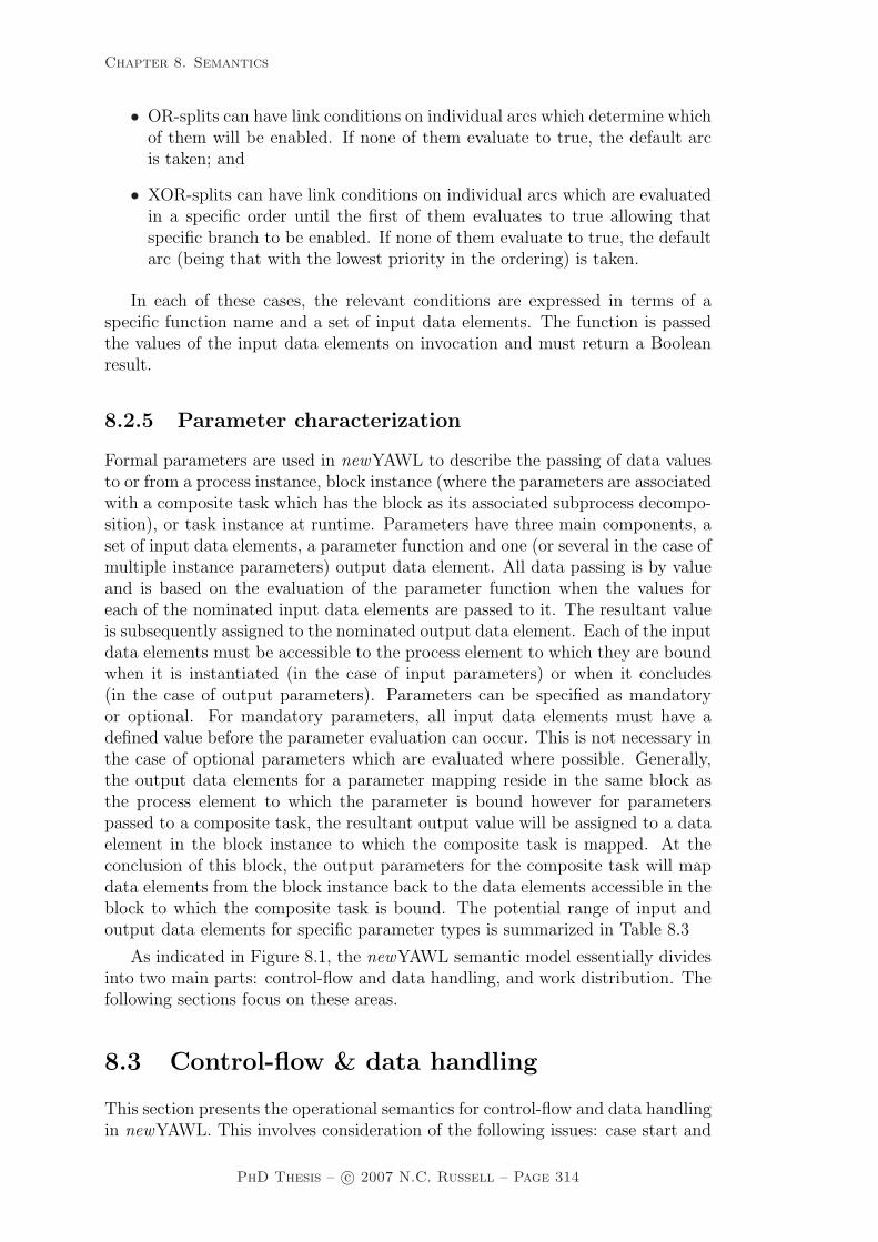
Chapter 8. Semantics
• OR-splits can have link conditions on individual arcs which determine whichof them will be enabled. If none of them evaluate to true, the default arcis taken; and
• XOR-splits can have link conditions on individual arcs which are evaluatedin a specific order until the first of them evaluates to true allowing thatspecific branch to be enabled. If none of them evaluate to true, the defaultarc (being that with the lowest priority in the ordering) is taken.
In each of these cases, the relevant conditions are expressed in terms of aspecific function name and a set of input data elements. The function is passedthe values of the input data elements on invocation and must return a Booleanresult.
8.2.5 Parameter characterization
Formal parameters are used in newYAWL to describe the passing of data valuesto or from a process instance, block instance (where the parameters are associatedwith a composite task which has the block as its associated subprocess decompo-sition), or task instance at runtime. Parameters have three main components, aset of input data elements, a parameter function and one (or several in the case ofmultiple instance parameters) output data element. All data passing is by valueand is based on the evaluation of the parameter function when the values foreach of the nominated input data elements are passed to it. The resultant valueis subsequently assigned to the nominated output data element. Each of the inputdata elements must be accessible to the process element to which they are boundwhen it is instantiated (in the case of input parameters) or when it concludes(in the case of output parameters). Parameters can be specified as mandatoryor optional. For mandatory parameters, all input data elements must have adefined value before the parameter evaluation can occur. This is not necessary inthe case of optional parameters which are evaluated where possible. Generally,the output data elements for a parameter mapping reside in the same block asthe process element to which the parameter is bound however for parameterspassed to a composite task, the resultant output value will be assigned to a dataelement in the block instance to which the composite task is mapped. At theconclusion of this block, the output parameters for the composite task will mapdata elements from the block instance back to the data elements accessible in theblock to which the composite task is bound. The potential range of input andoutput data elements for specific parameter types is summarized in Table 8.3
As indicated in Figure 8.1, the newYAWL semantic model essentially dividesinto two main parts: control-flow and data handling, and work distribution. Thefollowing sections focus on these areas.
8.3 Control-flow & data handling
This section presents the operational semantics for control-flow and data handlingin newYAWL. This involves consideration of the following issues: case start and
PhD Thesis – c© 2007 N.C. Russell – Page 314

Chapter 8. Semantics
ParameterType
BindingElement
InputDataElements
OutputDataElements
Incoming
Process Global, Folder Case, Block, ScopeBlock (via compos-ite task)
Global, Folder,Case, Block, Scope
Block, Scope
Task Global, Folder,Case, Block, Scope
Task
MI Task Global, Folder,Case, Block, Scope
Task, Multiple In-stance
Outgoing
Process Global, Folder,Case, Block, Scope
Global, Folder
Block (via compos-ite task)
Global, Folder,Case, Block,Scope, Task
Global, Folder,Case, Block, Scope
Task Task Global, Folder,Case, Block, Scope
MI Task Multiple Instance Global, Folder,Case, Block, Scope
Table 8.3: Parameter passing supported in newYAWL
completion, task instance enablement and work item creation, work item startand completion, task instance completion, multiple instance activities and datainteraction with the external environment. Each of these areas is discussed indetail.
8.3.1 Case commencement
The start case transition handles the initiation of a process instance. It isillustrated in Figure 8.3. Triggering a new process instance involves passing theProcessID and CID to the transition together with a list of any data folders thatare to be assigned to the process instance during execution. There are threeprerequisites for the start case transition to be able to fire:
1. The precondition associated with the process instance must evaluate to true;2. Any data elements which are inputs to mandatory input parameters must exist
and have a defined value (i.e. they must not have the UNDEF value); and3. All mandatory input parameters must evaluate to defined values.
Once these prerequisites are satisfied, the process instance can commence. Thisinvolves:
1. Placing a token representing the new CID in the input place for the process;2. Creating variable instances for any case data elements, block data elements for
the topmost block and scope data elements for scopes in the top-level block;3. Mapping the results of any input parameters for the process to the relevant
output data elements created in step 2; and
PhD Thesis – c© 2007 N.C. Russell – Page 315

Chapter 8. Semantics
4. Adding folder mappings to identify the folders assigned to the process instanceduring execution.
�������������� �� �������
�������� �������� ��� ���� �� �� ��������������������� ��� ������������ �� ������� ��������������� ������������ �� ����
���������� �� ������� ��� ���������������� ���������������������������� � ��������������� �� ��� ������� � �!�� ��
� �� ������������ "� �� �������� ���� � �� ���� "� �� �#�� ����
��������������� �� �������� �������� ����� ��������!$��!�� ��������
������
������
��� ���%����&��&��� �� ����� ����� ��� ��� ���� ��������'��� ������ ��� �� ���������� ��� ������������� ��� ��� ���������
Figure 8.3: Start case process
8.3.2 Case completion
The end case transition is analogous in operation to the start-case transitiondescribed above except that it ends a case. In order for a process instance tocomplete, three prerequisites must be satisifed:
1. The postcondition associated with the process instance must evaluate to true;2. Any data elements which are inputs to mandatory output parameters must
exist and have a defined value; and3. All mandatory output parameters must evaluate to defined values.
Once these prerequisites are satisfied, the process instance can complete. Thisinvolves:
1. Placing a token in the output place for the process;2. Cancelling any work items or blocks in the process instance that are still
executing;3. Mapping the results of any output parameters for the process to the relevant
output data elements;4. Removing any remaining variable instances for the process instance; and5. Removing any folder mappings associated with the process instance.
The execution of a work item involves the execution of a sequence of four dis-tinct transitions. The naming and coupling of these transitions is analogous to theformalization proposed in the original YAWL paper [AH05]. In the newYAWLsemantic model, the same essential structure for work item enactment is main-tained however this structure is augmented with an executable model defining
PhD Thesis – c© 2007 N.C. Russell – Page 316
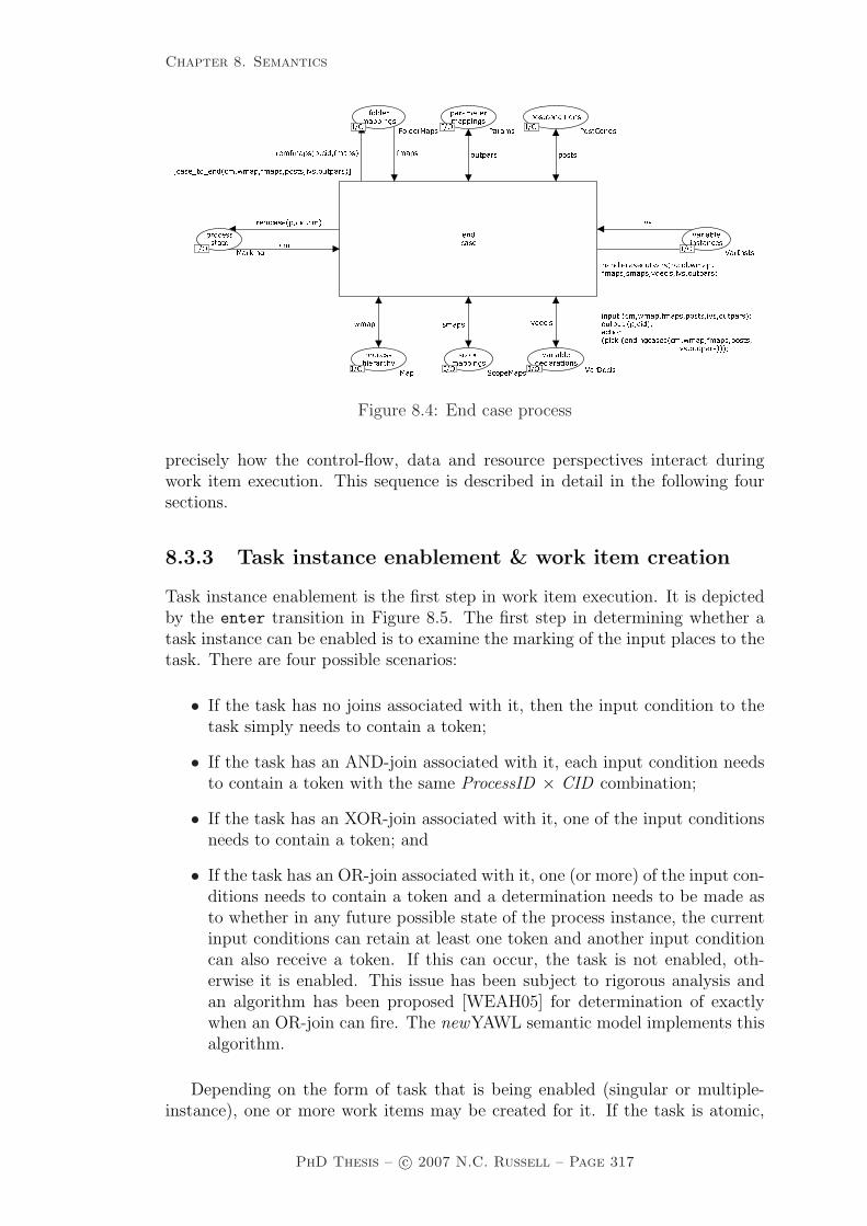
Chapter 8. Semantics
���������� �������������� ��������
����������� ��������
����� �� ������
������� � ������ ����������� ���� ����� ������ �� ����
������ �� ������ ��������������� ���� ��
�� �� ����� ������ �� �� �����
������� ������ ������� �� � � �� �� ��� ������ !��" ���� � � � ��������� !����������
������
������
���
��� ���#��$��$�� �������������������� �����������% ������ ���������� ��� ��������������������� ��� �������� ��� ���� �������������������� ����������� &������ ��� �� &�� ���� � ��� ����� �������������������� ������������� &Figure 8.4: End case process
precisely how the control-flow, data and resource perspectives interact duringwork item execution. This sequence is described in detail in the following foursections.
8.3.3 Task instance enablement & work item creation
Task instance enablement is the first step in work item execution. It is depictedby the enter transition in Figure 8.5. The first step in determining whether atask instance can be enabled is to examine the marking of the input places to thetask. There are four possible scenarios:
• If the task has no joins associated with it, then the input condition to thetask simply needs to contain a token;
• If the task has an AND-join associated with it, each input condition needsto contain a token with the same ProcessID × CID combination;
• If the task has an XOR-join associated with it, one of the input conditionsneeds to contain a token; and
• If the task has an OR-join associated with it, one (or more) of the input con-ditions needs to contain a token and a determination needs to be made asto whether in any future possible state of the process instance, the currentinput conditions can retain at least one token and another input conditioncan also receive a token. If this can occur, the task is not enabled, oth-erwise it is enabled. This issue has been subject to rigorous analysis andan algorithm has been proposed [WEAH05] for determination of exactlywhen an OR-join can fire. The newYAWL semantic model implements thisalgorithm.
Depending on the form of task that is being enabled (singular or multiple-instance), one or more work items may be created for it. If the task is atomic,
PhD Thesis – c© 2007 N.C. Russell – Page 317

Chapter 8. Semantics
the work item(s) is created in the same block as the task to which it corresponds.If the task is composite, then the situation is slightly more complicated and twothings occur: (1) a “virtual” work item is created in the same block for eachinstance of the task that will be initiated (this enables later determination ofwhether the composite task is in progress or has completed) and (2) a new sub-process decomposition (or a new block) is started for each task instance. Thisinvolves the placement of a token in the input place to the subprocess decomposi-tion which has a distinct subprocess CID. Table 8.4 indicates the potential rangeof work items that may be created for a given task instance.
�������
��������
���� ��
���
��� ��
�����
��� �� ������� ��������������� �������� ��� �������� � �� ������� ���������� ��� ��� ��� ���� ���� �� ��������� � ����
�� ����� ��������� � �������������� ���� ����� � ��� �� �� ������� ��
� ����������������������������� ��� � ����������
����� � ��� ��������� ��� ���������� � �� ����� � ��� �� �� ���������������������
������ �����
�����
���� ��
��� �� � ��� �� � �� ����� ������� ���� ����������� ��� ���� ����� ��� ������������ ����
������������ !" #����$��
� ��� �������� !" %� ��� �$������ ��������� �&'&��'����
���� � �������� !" (���
�� ��� !" )��*� ������������� � ���� !" $�������� �� � � !" '"+,#
�� ��� ������� ��-) ��� ��� �.� ���.� ���
����� � ��� !" %���&� �
�������� � !" $�����
������� � ���� !" (��+�������� !" - �
�������� ��� ���� !" / �*�� ����� !" -+) 0)�
��������� ���� !" /� �� ��� ���� � � �������� !" - � !"
!" !"
!"
!" !"
!"
!" !"
!" !"
!"
!"
!" ���� ���� ����������� ��� ���������� ��� ������������� ������������� ��� 1�� �� ������ ���� � ��� �� � � ������������ 1� ������ � � ������ ���� � 2��� ���� � ������� � ������ ������� ���� ������� ����� ��� ������������ ����� � �� 2 �� ��3 �� ��� �� ���� � � � ��� 2�� � � ������ � ���� � � 2 ��� ���� �� � ���������� ���� ���� � �� ���� ��� ������ ���� � ������� 2 ������ ��� �������� ���� ������ ���� � ��� �� �� ������������ ����1Figure 8.5: Enter work item process
Task TypeInstances Initiated at CommencementSingular Multiple Instances
Atomic Single work item created inthe same block.
Multiple work items createdin the same block, each witha distinct TaskNr.
Composite Single “virtual” work itemcreated in the same block anda new subprocess is initiatedfor the block assigned as thetask decomposition.
Multiple “virtual” workitems created in the sameblock. Additionally a dis-tinct subprocess is initiatedfor each work item cre-ated, each with a distinctsubprocess CID and TaskNr
Table 8.4: Task instance enablement in newYAWL
PhD Thesis – c© 2007 N.C. Russell – Page 318

Chapter 8. Semantics
In order for a task to be enabled, all prerequisites associated with the task mustbe satisfied. There are five prerequisites for the enter transition to be able tofire:
1. The precondition associated with the task must evaluate to true;2. All data elements which are inputs to mandatory input parameters must exist
and have a defined value;3. All mandatory input parameters must evaluate to defined values;4. All locks which are required for data elements that will be used by the work
items associated with the task must be available; and5. If the task is a multiple instance task, the multiple instance parameter when
evaluated must yield a number of rows that is between the minimum andmaximum number of instances required for the task to be initiated.
Once these prerequisites are satisfied, task enablement can occur. This involves:
1. Removing the tokens marking input conditions to the task for the instanceenabled. The exact number of tokens removed depends on whether there is ajoin associated with the task or not and occurs as follows:
• No join: one token corresponding to the ProcessID × CID combinationtriggered is removed from the input condition to the task;
• AND-join: one token corresponding to the ProcessID × CID combinationtriggered is removed from each of the input conditions to the task;
• XOR-join: one token corresponding to the ProcessID × CID combinationtriggered is removed from one of the input conditions to the task; and
• OR-join: one token corresponding to the ProcessID × CID combinationtriggered is removed from any of the input conditions to the task whichcurrently contain tokens of this form.
2. Determining which instance of the task this is. The instance identifer must beunique for each task instance and all work items and data elements associatedwith this task instance in order to ensure that they can be uniquely identified.A record is kept of the next available instance for a task in the task instance
count place.3. Determining how many work item instances should be created. For a singular
task (i.e. an atomic or composite task), this will always be a single work item,however for a multiple instance task (i.e. an atomic or composite multipleinstance task), the actual number started will be determined from the evalu-ation of the multiple instance parameter which will return a composite resultcontaining a number of rows of data. The number of rows returned indicatesthe number of instances to be started. In all of these situations, individualwork items are created which share the same ProcessID, CID, TaskID and Instvalues, however the TaskNr value is unique for each work item and is in therange 1...number of work items created ;
4. For all work items corresponding to composite tasks, distinct subprocess CIDsneed to be determined to ensure that any variables created for subprocesses arecorrectly identified and can be accessed by the work items for the subprocessesthat will subsequently be triggered;
PhD Thesis – c© 2007 N.C. Russell – Page 319

Chapter 8. Semantics
5. Creating variable instances for any data elements associated with the task.This varies depending on the task type and the number of work items createdfor the task:
• For atomic tasks which only have a single instance, this will involve thecreation of relevant task variables.
• For atomic multiple instance tasks, this will involve the creation of bothtask variables and multiple instance variables for each task instance. Therequired multiple instance variables are indicated by the output data ele-ments listed for the multiple instance parameter and this set of variablesis created for each new work item.
• For composite tasks that only have a single instance, any required taskvariables are created in the subprocess decomposition that is instantiatedfor the task. Also, there may be block and scope variables associated withthe subprocess decomposition that need to be created; and
• For composite multiple instance tasks, any required block, scope, taskvariables and multiple instance variables are created for each subprocessdecomposition that is initiated for the task.
6. Mapping the results of any input parameters for the task instance to therelevant output data elements. For multiple instance parameters, this can bequite a complex activity as illustrated in Figure 6.12;
7. Recording any variable locks that are required for the execution of the taskinstance;
8. For all work items corresponding to atomic tasks (other than for automatictasks which can be initiated without distribution to a resource), requests forwork item distribution need to be created. These are routed to the assign wi
to resource place and are subsequently dealt with by the work distribution
transition; and9. Finally, work items with an enabled status need to be created for this task
instance and added to the mi e place in accordance with the details outlinedin Table 8.4.
8.3.4 Work item start
The action of starting a work item is denoted by the start transition in thenewYAWL semantic model as shown in Figure 8.6. For a work item that corre-sponds to an atomic task, the work item can only be considered to be executingwhen a notification has been received that a resource has commenced executingit. This event is indicated by the presence of a token for the work item in thewi started by resource place. When this occurs, the start transition can fireand the work item token can be moved from the mi e place to the exec place.
A work item corresponding to a composite task can be started at any time.This simply involves changing the state of the work item from entered to exe-cuting, noting that a new subprocess has been initiated by adding an entry tothe list in the active nets place and initiating a new block (or subprocess de-composition) for the work item by placing a token indicating the subprocess CID
PhD Thesis – c© 2007 N.C. Russell – Page 320

Chapter 8. Semantics
in the input condition for the subprocess. Note that for work items correspond-ing to composite tasks, the start transition receives a notification to start thesubprocess, hence the exec place is updated with a work item corresponding tothe CID of the parent work item that initiated the subprocess and the list in theactive nets place links the parent work item to the subprocess that has beennewly initiated by this transition. ������ ��
���� ����
� ����� �������� � ���������� � ���� ��� � ��� �������������� ���������������� ���� �������� � ���������� ��� ��� �� ��������������������������������
�� ������� ������ �������� �� ������� � ��������� ������� ���� �� �������� ��� �������� ������ ��������� ��
� � ���������� ���� ������ �������� ������ ��!�� ���
� � �� ����� ���� ������ "���
�� �#�������� $ �%���� �������������� &����'������� ���
���������� � ������� &�������� ������
������
������
������
���(�� �# ���� ��������� �� ������� ����� �� ��� ������������ ������)��� � ��������� ����������� ������ *� �� � ������� �������� ��������� *�� ������� # � ������� ���� �� ���� � ��� �������� ����������� ����� �� ��� ������������ �������# � �� ����� �'���� �������������# � �� � ������ ������ ������� ���� ������������� ��� *
Figure 8.6: Start work item process
8.3.5 Work item completion
There are two distinct (but interrelated) transitions for completing an individualwork item. These are the terminate block transition that completes a workitem corresponding to a composite task and the complete transition that finishesa work item corresponding to an atomic task. Both of these transitions areillustrated in Figure 8.7.
The terminate-block transition fires when a subprocess decomposition cor-responding to a composite task has completed. This is indicated by a token forthe subprocess CID in the output condition for the block. When this occurs, theterminate block transition can fire and in doing so, any work items that arecurrently executing for this subprocess (or any children of it resulting from com-posite tasks that it may contain) are removed, similarly any markings in placesin the process model for this subprocess (or its children) are also removed. Fi-nally a work item is added to the mi c place indicating that the parent work itemcorresponding to the composite task which launched this subprocess is complete.
The complete transition fires when a work item corresponding to an atomictask is complete. This occurs when a notification is received (via a work itemtoken in the wi completed by resource place) that a work item assigned to aresource for execution has been completed. When this occurs, the state of thework item is changed from executing to completed by moving the work item fromthe exec to the mi c place.
PhD Thesis – c© 2007 N.C. Russell – Page 321
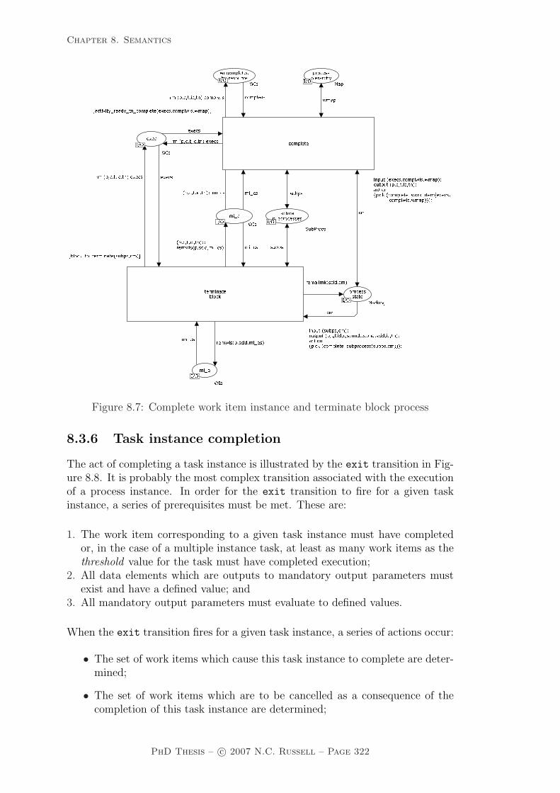
Chapter 8. Semantics
������ ���� ��� ��� � ������ ��
������ ������ ���� ������������� ��� � ������ �� ��� ������� ������� ��� ��� � �����
������ ��� ������� �����
�������������� ��� ���� �����
��� ��� � �����������
������� ������������������������ ������� ������� �
����� ������� ������� �� ���������������� �� ���� ���� ������� ������������������� ������� �
������������ �� ���� ����������������� ����������� ������ ������ ����������� ������ ������� ��� ���� ���� ������� �������������� ��������������� ������ �
� � ����������� ����������� ���
������� ������������������ �����!
������� ���������� ���
�������"�� �� ��"���� ��
��� ������������������ #��$�������
���
������
������
���
Figure 8.7: Complete work item instance and terminate block process
8.3.6 Task instance completion
The act of completing a task instance is illustrated by the exit transition in Fig-ure 8.8. It is probably the most complex transition associated with the executionof a process instance. In order for the exit transition to fire for a given taskinstance, a series of prerequisites must be met. These are:
1. The work item corresponding to a given task instance must have completedor, in the case of a multiple instance task, at least as many work items as thethreshold value for the task must have completed execution;
2. All data elements which are outputs to mandatory output parameters mustexist and have a defined value; and
3. All mandatory output parameters must evaluate to defined values.
When the exit transition fires for a given task instance, a series of actions occur:
• The set of work items which cause this task instance to complete are deter-mined;
• The set of work items which are to be cancelled as a consequence of thecompletion of this task instance are determined;
PhD Thesis – c© 2007 N.C. Russell – Page 322
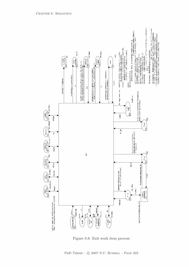
Chapter 8. Semantics
���� ���� ����� �� ��� ���� ��
�� �������� ��� ����� ���� ���� � �
�� �� ���� �� �� �� ���� �� ���
� ����
� ���� � �������� ����� ���� ��
� ��� ���
������
� �� ��
�� ��������� ���� � ����� ������� ����� ����
�� �� ���� � �� �� ����������
������ ���� � ����� ������� ����� ����
�� �� ���� �� ��� ����������
�� ��� ��� ����
��� ����������� � ��������� �� �� �� �����
��� ���� ���� � � �� ��� �� ����� ���� � ���� � ��� � ���
��
��
���� ��� ����� � � �� �� �� ����� � ��
�� ���
� ������ ��� � �� ������ � � ���� � ���� � ��� ��� ��� � ��
��� � � ���� ��� �� ��� ��� � ��� ��� � ���� ����
� ������ ���� � ���������
�� �� ���� �� ��� ����� ����
��� ���� ����� ���
���� �� �� �� �� ���� ���� ��� ��� ��� ���� �� ��� ���� �� �� �����
� ���
� �� � ��� ������� ��� � ����
��� � �� ���� � ! " ��#� ���
$ ����� % ���
� ���� ���� ��� � ! " ���� % ���
�� � �� ��������� ! ��& �
� �� ������ ���� ���� #% #�� ���
��� ���� � !' ��� ��� ����
�� ����� � ��� �� �� � � ! % ��
� �� � � ! & ��
�� �� � !& ��
������ ����(� �� (� ���� � ��� �� ��� � ! $� � (��
�� ����� �� ��� � ! % ��� ��
��� ����"�� ��� "�� ���� ��� ���� �� ���� � ! #���) ����
� ��� �� ����� � !*!)+ " ��� �� ��� ���� ����� � !, �� � ����
�� �� � !& ����� �� ��� �� �� �� �� ���� � ! , �� �� ���
�� �� � ! & )' �-' �� !
� ! � !
� !� !
� !
� !
� !
� !
� !
� !� !
! ��
� ! � !
� ����� ���� ��� � ! � ! � ����
� ��� � ��� � ��� �� � �� � �� ����� ���� � ���� ��� �� ��� � �� � ���� � ��� ��� � ���� ��������
���� ������ �� ������� ����� �� ��� � �� ����� � ���� �� ��� �����
�� ��� � �� �� ���� �� � ���� � ��� ����.
� ��� ���� � � �� � � ��������� ����� ���� � ����� ����
� ���� ��� ��� ��� � ��� ����� ��
��������� ���� �� � ���� �� �� �� �����.
��� ��� ���� ����� � � �� � ��/ � ���� ��� � ��� ��� ��� �� � �� � �� ����� ���� � ���� ��
� �� ��� � �� � ���� � ��� ��� � ���� ���� ����
���� ��������� ����� ���� � ����� �����/�� �������� � �� ���
���� ���� ���/ ��� ���� ����� � ����
��� ��� ���/ � �� ���� � � �� ���� ���
���� ���/ ��� � ��� ������� � � �����
��� ����� ��/ ���� ������� � � �� �� ����
��� ���������/ �� ������� ����� � ���� ��� �������� ��� �� ������ �� ���� �� �����
� � � �� ��� �����
������ ��� ���� ��/� ��� ��� ��������� � ����� ���� � �� ������ �� ���� �� ���
���� ���������
���� ���� ��/� ������ �� ���������� �� ������ �� �� � � � ����� �����
����� �� ����/�� ����� ����� ���� ���� �� � ���� ��� � �����
���� � � �� � � ��������� ����� ���� � ����� ���� � ���� ��� ��� ��� � ���
����� �� ��������� ���� �� � ���� �� ���� ������ ���.
Figure 8.8: Exit work item process
PhD Thesis – c© 2007 N.C. Russell – Page 323

Chapter 8. Semantics
• The set of work items which are to be force completed as a consequence ofthe completion of this task instance are determined;
• The set of subprocess instances that are to be terminated as a consequenceof the completion of this task instance are determined, e.g. for a partial joincomposite multiple instance task;
• All work items (including those in subprocesses of this task instance) cur-rently in the enabled, executing and completed states that are to be cancelledor force completed are removed from the lists in the mi e, exec and mi c
places;
• All subprocesses instances which are completed or terminated by this taskinstance are removed from the list in the active nets place;
• All output parameter mappings for this task instance are evaluated and therelevant output data elements are updated. In the case of a task instancewhich has multiple work items, the multiple instance data elements fromindividual instances are coalesced as illustrated in Figure 6.13. Note thatit is possible that some data elements may be undefined where not all workitems corresponding to the task instance have completed;
• All data elements for work items associated with this task instance as well asthose for subprocesses of this task instance and work items to be cancelled(but not force-completed) by this task instance are destroyed and removedfrom the list in the variable instances place;
• Any locks on variables that were held by the task instance are released;
• Cancellation requests are sent to the work distribution transition for anyatomic work items that are enabled or currently executing and are beingcancelled as a consequence of the completion of this task instance;
• Any tokens in conditions in the process model to be cancelled by the com-pletion of this task instance are removed (including those associated withsubprocesses);
• Any conditions on outgoing links from this task are evaluated and tokensare placed in the associated output places. For a task without any splits orwith an AND-split this means tokens are placed in all output conditions.Where the task has an associated OR-split, they are placed in the outputcondition for each link which has a link condition which evaluates to true(or the default condition if none of them evaluate to true) and for a taskwith an XOR-split a token is placed in the condition associated with thefirst link-condition to evaluate to true (or the default if none evaluate totrue).
In general, the exit transition results in the completion of all work items as-sociated with a task instance, however in the situation where a task has multipleinstances and its specified completion threshold is lower than the maximum num-ber of instances allowed and the remaining instances are not cancelled when the
PhD Thesis – c© 2007 N.C. Russell – Page 324

Chapter 8. Semantics
task instance completes, it is possible that some related work items may continueexecuting after the task instance has completed. These work items are allowed tocontinue execution but their completion will not result in any further action orother side-effects, in particular the exit transition will not fire again and no dataelements will be retained for these work items.
8.3.7 Multiple instance activities
Where a task is specified as being multiple-instance, it is possible for several workitems associated with it to execute concurrently and also for additional work iteminstances to be added dynamically (i.e. during task execution) in some situations.The add transition in Figure 8.9 illustrates how an additional work item is added.The prerequisite conditions for the addition of a work item are:
• The task must be specified as a multiple-instance task which allows fordynamic instance addition; and
• The number of associated work items currently executing must be less thanthe maximum number of work items allowed for the task.
����� ������ ��
�� ��
��� �� � � ����� �� ����������������� ������ ���������������������� ��� � ��� � ���������
� �� ��
��� ����� ��� ���������� � �� ������ ��� ������ ����
����� ��������� ��������� � ������� ������ ��� � ��� �� �� � ��
�������
�� �� ������ ����� �� �� ����� �������� ����� ��������� �� ����� � !"���
�� ���!�� �� ��� �� ���� #��$ ����� �� ��� %&'�
�� ���!�� ��� ���� #��� ���
������ ������ ����� "�����
������� %&'�('�
������� ������ '���$�� ������ �� ���� ��� ���� %��
������ %��������� �� ������ ������
���
������
���
���
���
������
������������ ��� !������
)� ����� � ��� ������ ������� �����*� � � ������ ��� !������������������� ����� +� �� � � ������ ������ ����� �+�� �� ��� ������ ������������� � ����� ��� �� ,�� !��� ����� !�������������� ���������������� �������������������� ,�� ������ ��� ������ +
Figure 8.9: Add work item process
Where an additional work item is created, the following actions occur:
1. The task instance is recorded as having an additional work item associatedwith it;
2. An additional work item is created with an enabled status and added to themi e place (note that this work item shares the same ProcessID, CID, TaskIDand Inst as the other work items for this task instance but it has a uniqueTaskNr); and
3. If the task is atomic, then a request is made to the work distribution tran-sition for allocation of the work item to a resource for execution.
PhD Thesis – c© 2007 N.C. Russell – Page 325

Chapter 8. Semantics
8.3.8 Data interaction with the external environment
Support is provided for data interaction between a given process instance and theoperating environment via push and pull interactions with variables supportedby the newYAWL environment or those which may exist outside of the processenvironment. A push interaction allows an existing variable instance to be up-dated with a nominated value from another location. A pull interaction allows itsvalue to be accessed and copied to a nominated location. Push and pull interac-tions are supported both in both directions for newYAWL data elements. Eachvariable declaration allows these operations to be explicitly granted or denied ona variable-by-variable basis. Figure 8.10 illustrates how these interactions occur.
������ ��� ��������� �� ���� �� ��� �� �
� ������ �
� ��
��������
���
�����
���� � ���� � �� ��
�� �� �� ���������� ����������� �� ���� �� ��� �� �
� �� � ������������ ���� ��� ��� �� ���������������� �
��������� �� ����� ��� ������ �� ������� � ��
��� ��������� ���� �� ������ �� ������� � ��
���� �� ���� �� �������� ������� � ��
��� ��������� ����� ��� ������ �� ������� � ��
���� �� � ������ �� ������� �� � �� ��� ���� ���
���� �� � ��������� �� � �� ����������
���� �� � �� ����� ����
�� �������� �� �� ��� �� ����� � �� ������� ����� �� ���� �
���� �� � ����������
���� �� � �� �������� �� �������� !����
���� �� � ������� �� ����� ��
���������� ���� ��� ��� �� ���������������� ���� ���� � ���� ��������� �
Figure 8.10: Data interaction between newYAWL and the operating environment
8.4 Work distribution
The main motivation for PAIS is achieving more effective and controlled distri-bution of work. Hence the actual distribution and management of work items areof particular importance. The process of distributing work items is summarizedby Figure 8.1147. It comprises four main components:
• the work item distribution transition, which handles the overall man-agement of work items though the distribution and execution process;
47Note that the high-level structure of the work distribution process is influenced by theearlier work of Pesic and van der Aalst [PA05].
PhD Thesis – c© 2007 N.C. Russell – Page 326
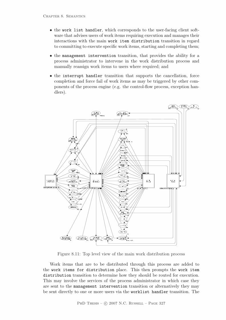
Chapter 8. Semantics
• the work list handler, which corresponds to the user-facing client soft-ware that advises users of work items requiring execution and manages theirinteractions with the main work item distribution transition in regardto committing to execute specific work items, starting and completing them;
• the management intervention transition, that provides the ability for aprocess administrator to intervene in the work distribution process andmanually reassign work items to users where required; and
• the interrupt handler transition that supports the cancellation, forcecompletion and force fail of work items as may be triggered by other com-ponents of the process engine (e.g. the control-flow process, exception han-dlers).
���� �������� � ����� ��������� ��� ������� ���� ��� ����� �������� ����� ��� ����� ����������������� ����� �������������� ���� ����� ��� ���������� � ��� ��������� � �
������������� ����� ��������
��� ���������� ����� ��������������
�� ��� �� ������ ���������� ���� �� �� � �� �� ������ ��
�������������� ���� � ��������������������� ���� ������� �� ������ ����� ��
��� ��� ��� �� ����� � ���� �� ������ ��� �� ����� ��
���������� �������� ���
���� �������� ��� ����� ������ ���
����� ���� ���� ��� ���� ��������� ���� ��� ��������� ��� ��� ���������� �� ��� ���
��� ������� �������� ����
������ � �� ��� ������ � ��������� �� ��������
� � ������� ����� ���������� ������ ����� �������� � �� ������� ���� ����������� ������ � �� ������������� ��� � �� ���������� ������� �� ���� � �� ��� ���
��� � �� ���������������� � ������������� � � �� ��� ������� ���� � ��
������� ������������� ��������� �� ���
����� ������
��!� �� ����� � ������� � � ��� ���� ���������� � ���
���� � ���������
���
�����
����������� � ������������ ���� ����� ��� ����� ����� ��� ����� ��� ���� ��������� ��� ���
Figure 8.11: Top level view of the main work distribution process
Work items that are to be distributed through this process are added tothe work items for distribution place. This then prompts the work item
distribution transition to determine how they should be routed for execution.This may involve the services of the process administrator in which case theyare sent to the management intervention transition or alternatively they maybe sent directly to one or more users via the worklist handler transition. The
PhD Thesis – c© 2007 N.C. Russell – Page 327

Chapter 8. Semantics
various places between these three activities correspond to the range of requeststhat flow between them. There is a direct correspondence between these placenames and the interaction strategies illustrated in Figure 6.14. In the situationwhere a work item corresponds to an automatic task, it is sent directly to theautonomous work item start place and no further distribution activities takeplace. An automatic task is considered complete when a token is inserted in theautonomous work item finish place.
A common view of work items in progress is maintained between the work
item distribution, worklist handler and management intervention tran-sitions via the offered work items, allocated work items and started work
items places. There is also shared information about users in advanced operat-ing modes that is recorded in the piled exec users and chained exec users
places. Although there is significant provision for shared information about thestate of a work items, the determination of when a work item is actually com-plete rests with the work item distribution transition and when this occurs,it inserts a token in the completed work items place. Similarly, work item fail-ures are notified via the failed work items place. The only exception to thesearrangements are for work items that are subject to some form of interrupt (e.g.an exception being detected and handled). The interrupt handler transitionis responsible for managing these occurrences on the basis of cancellation, forcecompletion and failure requests received in the cancel work item, complete
work item and fail work item places respectively.
All of the activities in the work distribution process are illustrated by sub-stitution transitions indicating that each of them are defined in terms of signif-icantly more complex subprocesses. The following sections present the CP-netmodels for each of them.
8.4.1 Work item distribution
The work item distribution process, illustrated in Figure 8.12 and 8.13, sup-ports the activities of distributing work items to users and managing interactionswith various worklist handlers as users select work items offered to them for laterexecution, commence work on them and indicate that they have completed them.It also support various “detours” from the normal course of events such as deal-location, reallocation and delegation of work items. It receives work items tobe distributed from the enter or add transitions which forms part of the maincontrol-flow process and sends back notifications of completed work items to thecomplete transition in the same process. The main paths through this processare indicated by thick black arcs. In general, the places on the lefthand side of theprocess correspond to input requests from either the main control-flow processor from the management intervention or worklist handler processes that re-quire some form of action. Typically this results in some form of output that isillustrated by the places on the righthand side of the process.
PhD Thesis – c© 2007 N.C. Russell – Page 328

Chapter 8. Semantics
One of the most significant aspects of this process is its ability to managework item state coherence between itself, the worklist handler and management
intervention process. This is a particular problem in the face of potential raceconditions that the various parties (i.e. users, the process engine, the processadministrator) involved in work distribution and completion may invoke. This ismanaged by enforcing a strict interleaving policy to any work item state changeswhere user-invoked changes are handled first (and are reflected back to the user)prior to any process engine or process administrator initiated changes. Externalinterrupts override all other state changes since they generally result in the workitem being cancelled.
8.4.2 Worklist handler
The worklist handler process, illustrated in Figure 8.14, describes how theuser-facing process interface (typically a worklist handler software client) operatesand interacts with the work item distribution process. Once again, the mainpath through this process are indicated by the thick black arcs. There are varioustransitions that make up the process, these correspond to actions that individualusers can request in order to alter the current state of a work item to more closelyreflect their current handling of it. These actions may simply be requests to startor complete it or they may be “detour” requests to reroute it to other users e.g.via delegation or deallocation.
8.4.3 Interrupt processing
The interrupt processing process, illustrated in Figure 8.15, provides facilitiesfor intervening in the normal progress of a work item where required as a result ofa request to cancel, force-fail or force-complete a work item received from externalparties.
8.4.4 Management intervention
The management intervention process, illustrated in Figure 8.16, provides fa-cilities for a process administrator to intervene in the distribution of work itemsboth for clarifying which users specific work items should be distributed to andalso for escalating non-performing work items by removing them from one (orseveral) user’s worklist and placing them on others, possibly also changing thestate of the work item whilst doing so (e.g. from offered to allocated).
The preceding subsections (8.4.1 – 8.4.4) summarized the major components ofthe work distribution, worklist handler, interrupt processing and managementintervention processes. Underpinning the first three of these are a series of indi-vidual activities that describe their fundamental operation. The following sub-sections present each of these individual activities in detail.
PhD Thesis – c© 2007 N.C. Russell – Page 329

Chapter 8. Semantics
Figure 8.12: Work item distribution process (top half)
PhD Thesis – c© 2007 N.C. Russell – Page 330
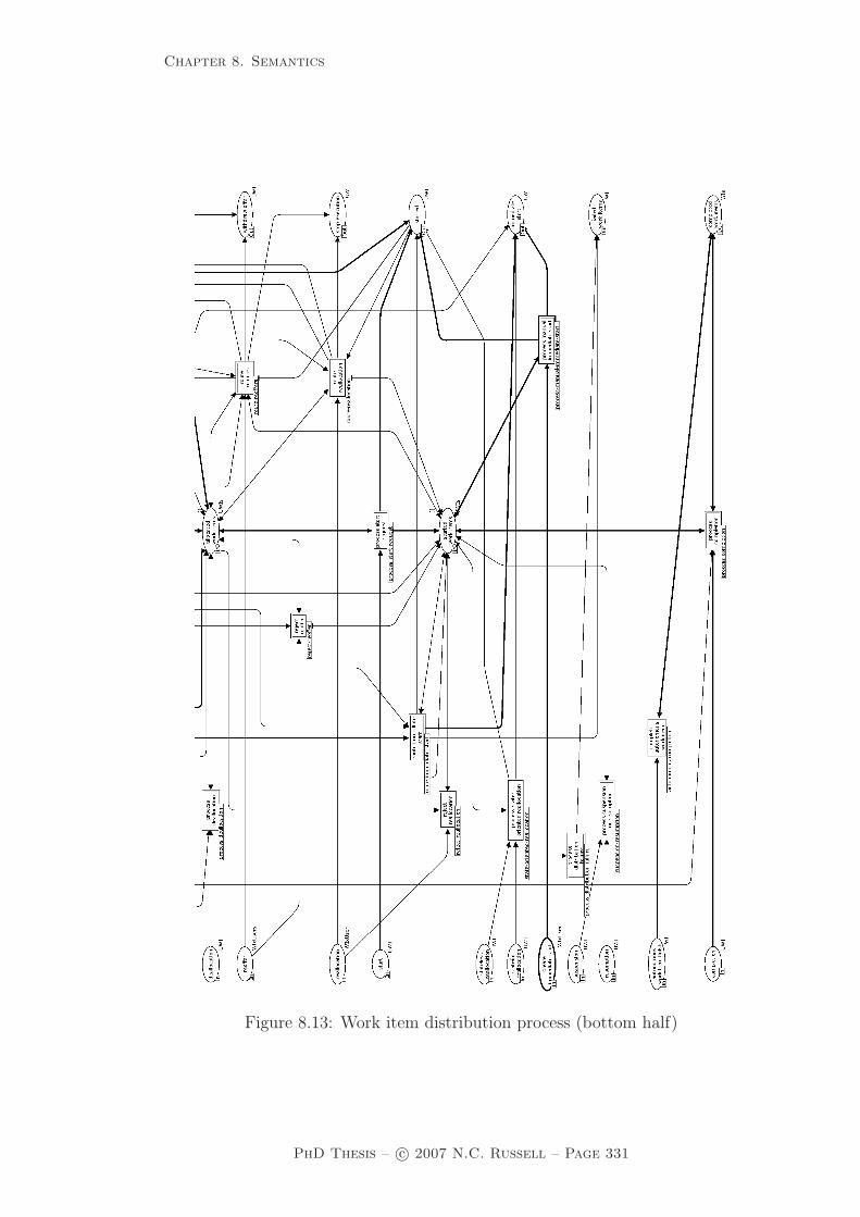
Chapter 8. Semantics
Figure 8.13: Work item distribution process (bottom half)
PhD Thesis – c© 2007 N.C. Russell – Page 331

Chapter 8. Semantics
�� �� �������� �������
���� ������� �������� ������� � ����
��� ����� ��
����� ������� ������������ ����� ��� �������������� ���� �������������� �� ��� �������
��� ������� ����� �������� ���� ���������� ��� ������
��� ���������� ��������� �������� ������
� ��� �� ��������������� ���� � ��������
���������� ����������
���� �� �������������� ������ � ����� ��������� ������� ����� ������� ���� ������� ��� ����� �������� ������� ������� ����� ����������� ������� �������� ������ ������� ����
��� ����� ���
���������� ��� ���
����� ������� ���������� ���������� ���� ���������� ���
�� ��������� ������ ���������� ���
��� ������� ��� ��� �������� ������������ ������ ����� ���� ������ ��� ���� ������ ����������� ������
� �������� ������������ ������ ����
����� ������� �� ������� �� ��� �� ������� ������
���������� ���
��������� ����
���
�����
� ����������
������
������
�
�
��� ��� ��� ��� ����� ����
���������
�������
��� ��������� ��
�� ��������� �������
�� ��� ��������� �������� ��������� �� ��� ������������ ����� ��� �������
��� ��
���� ������� � ����
� �������
�� ��������
Figure 8.14: Work list handler process
PhD Thesis – c© 2007 N.C. Russell – Page 332

Chapter 8. Semantics
� ��� ���� �� � ��� ����� ��� �� �� ���� �� �� �� ����� ���
����� ���� �� ����� ����� ���
� ��� ��� �� � ���� �� � ���� ��� �������
���� �� � � ��� ��� ��� �� ��� ���� � �
�� ��� � � � �� ����� � � � �� �
� ���� ���� �� � � ��� ��� �� � ���� �� � ���� ��
��� �� ���� �� � ��� �� � �������� � ���� �� � ��� �� � ��� ��� � ���� �� � ��� �� � �
�� �� ���� �� � �� � � ��� ���� �� � �� �
�� �� � � �� �� �
����� ���� �� � �� �
�� � � � �� ��� � �� �� ������ �� � ��� � � �� �� �� �� � ��
� � � �� �
������ ���
��� � ��
� � � ����
���
����� ����� ��� �� �� ����� ��� � ��� ����� ��� � ��
Figure 8.15: Interrupt handling process
PhD Thesis – c© 2007 N.C. Russell – Page 333

Chapter 8. Semantics
�� ������ �
��
�� ���� ��������� �������� ���
�� ���� ��������� ��������� ���� ������ ��� �������
���� ��
���� ��
�� ����
�� �����
��� ���� ������ ��� ������
�� ���� ������ ��� �������
�� ��
���� ��
�� �� � ��������
� �
����� ������ ���� ��� ������ ������� ������ � ������ ������������ ��������� ���� ��� ������ ���� ���� ��� ���� � �� ���� ������������ �� �������� ���� � ������ ����� ���� ���� ��� ���� � �� ���� ������������ ������
���� ����� ������ ����� � ������ ������������ �� ���
���� �������� � �� ���� ����������� ����� ���� ��� ��� �� ����
�� �������� �������� ������ ������ ����������� ����
������ ��� �� ������ ��� ���� � ��
����� ������ ���� ��� �� � ! � ���������� ���� ��� ��"�� ! #$�� ���� �������� ����� %" $! �
� ������ ������ ���"�� ! #$���
� ��������� ��"�� ! #$����
� ������������ ����� %" ��$! �
���� ������� ����� %" $! �
������� ���� ��$�� ��$����$���� �$�� �$���
��� �������"�� ! #$���
������ �"�� ! #$��������� ����� � � !
����� �� ������ ��� � ! �
�"��
"��$����
%"
%"
"��
"��
%""�� �
Figure 8.16: Management intervention process
PhD Thesis – c© 2007 N.C. Russell – Page 334
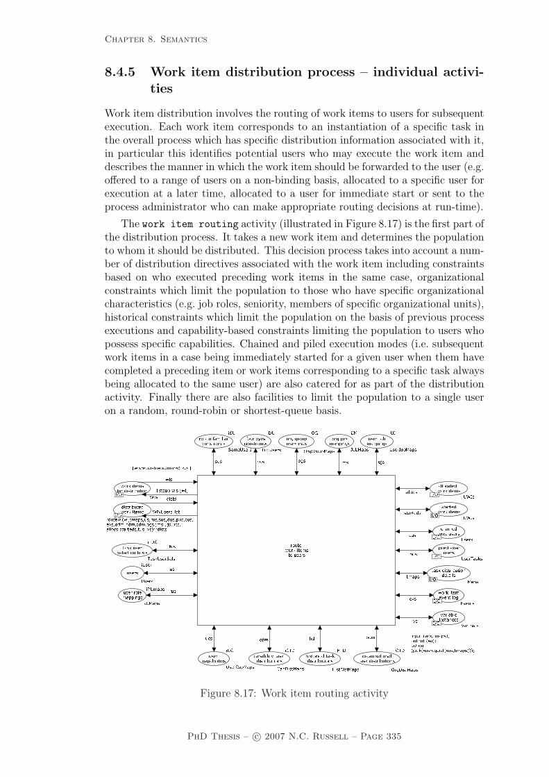
Chapter 8. Semantics
8.4.5 Work item distribution process – individual activi-ties
Work item distribution involves the routing of work items to users for subsequentexecution. Each work item corresponds to an instantiation of a specific task inthe overall process which has specific distribution information associated with it,in particular this identifies potential users who may execute the work item anddescribes the manner in which the work item should be forwarded to the user (e.g.offered to a range of users on a non-binding basis, allocated to a specific user forexecution at a later time, allocated to a user for immediate start or sent to theprocess administrator who can make appropriate routing decisions at run-time).
The work item routing activity (illustrated in Figure 8.17) is the first part ofthe distribution process. It takes a new work item and determines the populationto whom it should be distributed. This decision process takes into account a num-ber of distribution directives associated with the work item including constraintsbased on who executed preceding work items in the same case, organizationalconstraints which limit the population to those who have specific organizationalcharacteristics (e.g. job roles, seniority, members of specific organizational units),historical constraints which limit the population on the basis of previous processexecutions and capability-based constraints limiting the population to users whopossess specific capabilities. Chained and piled execution modes (i.e. subsequentwork items in a case being immediately started for a given user when them havecompleted a preceding item or work items corresponding to a specific task alwaysbeing allocated to the same user) are also catered for as part of the distributionactivity. Finally there are also facilities to limit the population to a single useron a random, round-robin or shortest-queue basis.
������
������
���
��� ����
��� ���������� ����� ��� ��
�� �� ���� �� �� �������� �� ���
������������������� � �����
� ���������� ������� !"���� ������ ������� !"���� ��� ��� ��� ��� ��� �� �#!$#�� !���$� �� ����� �%����� ����� !���#�� ���� �����%�� ��� ����� !������� ������� ������ &������� � �� ���������� �'!����'!(��� �� � �� ���� ������ ������ #(������ �� �!�� �!����
� ������� ���� ��� � �� ���� ������#)���)��(������ ��������� ��� �!*!�� �*��(��� �������� � �� � �� ���� ���� �+#)+��)��(���
��� � ���������� �!,!���,��(���-��� �.������ �� ��� �)!)�--!�� ��
��������. �� � �� ���� ���� �*#)*��)��(���
� �� ���������� �,(,��(������ � ������������ ��/���/����(������ �� -������ ����� �� ��� �$!$���!����
������������������
�������
� �� ��������� ������������������ ���������� ��������������������������������������������������� �������� �������� ���� 00� ���"�%!����1��"����� ����-� � � �� ���� ��������� ��������� �� ��� ��� ��� � ������� ������������������������ �� �������� 2���� �� �� 2�� ������� �� �� ���� �� �� ���������� 2Figure 8.17: Work item routing activity
PhD Thesis – c© 2007 N.C. Russell – Page 335

Chapter 8. Semantics
The process distribution failure activity (illustrated in Figure 8.18)caters for the situation where the work item routing activity fails to identifyany users to distribute a work item to. In this situation, the work item is simplynoted as having failed and is not subject to any further distribution activities.������� � ���� �� ����� �� ���� ������� ��� ����� ����� ��� ���� ����� ��� �� ����� �� ��� �� �� �� ����� ���� �� � �������� ���� �� ��� ����� ��� �� ������� ��� ������� �������� ��� ��� ���������� �������� �������� ������ ���
Figure 8.18: Process distribution failure activity
The route offers activity takes a distributed work item which is to be offeredto one or more users and (based on the population identified for the work item)creates work items for each of these users which are then forwarded for insertionin their respective work lists. It is not possible for the activity to execute fora work item that is to be distributed to a user operating in chained executionmode (regardless of the original distribution scheme specified for the work item).This is necessary as any work items intended for chained execution users mustbe started immediately and not just offered to users on a non-binding basis. Italso ensures that the work engine records the fact that the work item has beenoffered to the respective users.
������� � ���� �� ����� �������� �� � ���������� ���� ��������� ����������� �� �� ���� �������� �� ��� �� ������� ��� ����� ��������� ���� ������� � ��� ����� ������� ������ � !��� !���
���� ��� ��� �������� ����� ��� ������������� ��������"������
������ ���
�������� �� ���� �������� #������ � ���� #� � ��� ��� ���������� �� �� ���� ���������� #������ �� � ����$$� �����
Figure 8.19: Route offers activity
The route allocation activity (illustrated in Figure 8.20) takes a distributedwork item which is to be directly allocated to a user and creates a work item forinsertion in that users’s worklist. It also ensures that the work engine records thefact that the work item has been allocated to the user. As for the route offers
activity, it is not possible for this activity to execute for a work item that is tobe distributed to a user operating in chained execution mode (regardless of theoriginal distribution scheme specified for the work item).
The route immediate start activity (illustrated in Figure 8.21) takes a dis-tributed work item which is to be directly allocated to a user and started im-mediately, and it creates a work item for insertion in that users’s worklist. Italso ensures that the work engine records the fact that the work item has beenallocated to the user and automatically started. As for the route offers androute allocation activities, it is not possible for this activity to execute fora work item that is to be distributed to a user operating in chained executionmode as this is handled by a distinct activity. In order for the work item to be
PhD Thesis – c© 2007 N.C. Russell – Page 336

Chapter 8. Semantics
������� � ���� �� ����� ��� �� � ������������ ���������� ����� ���� �������� ���� ������ ��� �� ��������� ��� � �� ���� �������� �� ��� ����� �� ���� �������� ������� � ������ � ��� ��� ������� ��� � �� ���� ���������� �
�� ������� ��� ����� ������ ��� ������� �������� � ��
�� �� ������ � �� ��� �� ������ � ����� � ��� ����� ������� ������ !"���� ��� ������� ����� �������#��������� ���������
���
Figure 8.20: Route allocation activity
automatically started for the user, that user must either have an empty worklistor have the concurrent privilege allowing them to execute multiple work itemssimultaneously. If a user does not have this privilege and already has an execut-ing item in their worklist, then the work item is regarded as having failed to bedistributed and no further action is taken with it.
������� � ���� �� ����� �������
� ��� ���������� �� � �������� ����� �� � ���������� ���������� �� � �������� ����� �� � ���������� ���������� �� � �������� ����� �� � ���������� ����� ���� �� �������� ����� �� � ������������� �� ������� �� � � ��� �����
����������� ��� ������� ����� ���� ��� ���������� ��� �� ���� ��� �������� �� �������� �� ���� ��� �������� ������ � ���� � � ��� ��� ��������� ��� �� ���� ��� ���������� �� �����!� ��� ��"#$ %����
���� � ��� ����� ������� ���"#$ &'���
��� ������� �����"#$ %("������ ������� ��$�� %("��� ����$�� %("� ��� �������("�"#$ ("!%���� )���
��� ����� ���*��%���+���� �%+%���+������ ������� �����$�� ("$��
%���+����"#$ $��$��
"#$
"#$
"#$Figure 8.21: Route immediate start activity
The manual distribution activity (illustrated in Figure 8.22) is responsiblefor forwarding any work items that are recorded as requiring manual distributionto the process administrator for action.������� � ���� �� ����� � ���� ��� ���� ����� �
���� �� ������ ��� ���� �� ���� � ��� ��
���� ����� ���� ��� ��� ���������� ��� ����
���� �������� ����� �� ���� �� ������ ������ �������������
��������� ��� � ������ �� ����� ���� ������� � ���� ���� ��� ������ ���� �� ����� �� ����� ������ � �� �������� �� ����� ���� ������� � ���� ���� ��� ������ ���� ����� �� �� ����� ������ � ��� � � ��� ����� ������� ���������
� ���� ����� �� �� ����� ���� � �����!"����#��� � ����� ���� �� ����� �� ����� ���� � ��� ����� �� ����� ����������� � ���� ���� ��� ������ ���� ������ �� ����� ������ �� ����� ���� ������ �� ����� ���� � ���� ����������� � ���� �� �����
������� � ���� �� �����Figure 8.22: Manual distribution activity
PhD Thesis – c© 2007 N.C. Russell – Page 337

Chapter 8. Semantics
The route manual offers activity (illustrated in Figure 8.23) takes any workitems that have been identified by the process administrator to be offered to usersand creates work items for those users for subsequent insertion in their worklistswith an offered status. �� ���� ����� ��� �� �� ����� �������� ����� �� ��� ������ ���� �������� � ��� ��� �������� ���������
Figure 8.23: Route manual offers activity
The route manual allocation activity (illustrated in Figure 8.24) takes anywork items that have been identified by the process administrator to be allocatedto a user and creates a work item for subsequent insertion in the user’s worklistwith an allocated status. ���� ������ ���� ���� ���� ���� � ���� ���
� ��������� ������ ������������
� ���� ���� ����� �����������
� ���������� ���� ������������� ����������� ���
Figure 8.24: Route manual allocation activity
The process manual immediate start activity (illustrated in Figure 8.25)takes any work items that have been identified by the process administrator to beallocated to a user and directly started, and creates a work item for subsequentinsertion in the user’s worklist with a started status.
����������� �� ���� ���� ���� �� �� ���� ���� ��� ����� ������ ���� ��� ����� ������� ��� ����� ����� ������ ���� ��� ���� �������
��� �������� �������� ���� ����� ������� ����� �����������
���Figure 8.25: Process manual immediate start activity
The autonomous initiation activity (illustrated in Figure 8.26) provides anautonomous start trigger to work items that execute automatically and do notneed to be assigned to a user. It is anticipated that this trigger would be routedoutside of the process environment in order to initiate a remote activity.
The autonomous completion activity (illustrated in Figure 8.27) respondsto a trigger from an external autonomous activity indicating that it has finished.It forwards this response to the process engine allowing it to enable subsequentactivities in the process.
PhD Thesis – c© 2007 N.C. Russell – Page 338

Chapter 8. Semantics
�������� �� �� �� ��� � �� �� ���� �� ������������ �� �� ������ ��� �� ������� �� ��� ����� �� ������� ������� �� �� ��� ������� ��� ������ ��� �� ��������� ���� � ��� ����� ���� � ������ ���� ���������� ����� ����� �� �� ��� ����� ������ ������ ���
���
Figure 8.26: Autonomous initiation activity���� � � ���� ���������� ��������� ����� ��������� �� � � ���� �� ���������� ������ ������� Figure 8.27: Autonomous completion activity
The process selection request activity (illustrated in Figure 8.28) re-sponds to a request from a user for a work item to be allocated to them. Ifthe work item is one that is defined as being started by the user, then the workitem is recorded as having an allocated status and the user is advised that it hasbeen allocated to them. If is one that is automatically started on allocation, thenit is recorded as having a started status and the user is advised of this accord-ingly. In both cases, any offers pending for this work item for other users arewithdrawn thus ensuring that these users can not request that the work item besubsequently allocated to them.
�� �������� ��� �� � ��� �� ���������� �� � ��� ��� ����� ����� ���������� ���
����� ����� �� ���
�� ���� ����� ����� ����� � ����
��� � �� �!� ������ ���� � "#���� ����� ���� �� ����� ����� ���
���� ����� ����� � ���� � ���������� ����� � ����
�� ������� ���
$%���
��
� �� �
�� ��� �
� ���
������ �
�� �� ��� �� ���� ����� �� ������ �� ��� ��� �&���
�%����� ��� ����%�� ��'� �� � �%������'�� �� ���( �� ��� ���������
�� ��� �� � ��� �� ���������� ���) � ��� (*�� ��� ��� �� � ��� �� ���������� ���) � ��� (*�� ��� ��� �� � ��� �� ���������� (*�� � � ��� ���)���� ������ � �� �� ���� ����� ��� �� � ��� �� ���������� ���) � ��� (*�� �
�� �� ����� ��� �� � ��� ������������ ��� �� � ��� ��������� �� �� ��
Figure 8.28: Process selection request activity
PhD Thesis – c© 2007 N.C. Russell – Page 339

Chapter 8. Semantics
The reject offer activity (illustrated in Figure 8.29) handles requests fromusers for a work item previously offered to them to be allocated to them wherethe work item in question has already been allocated to a different user. Theserequests are rejected and the requesting user is advised accordingly.
�� ��� ����� �������� � � �� �� �� ��� ����������� ������� ��� ���� ��� ���� ������ ����� �������
���Figure 8.29: Reject offer activity
The process start request (illustrated in Figure 8.30) activity responds toa request from a user to start a work item. It can only start the work item if it hasbeen previously allocated to the same user. Where it has, the status of the workitem is changed from allocated to started and the user is advised accordingly.
������ �� ������������ ������ �� �� ��� ��
�� ��� ��� ���� ������� �� ������� ����� ��������������� ������������
�� ����� ����� ��� ���� ����������� ������� ������ ������� ������� �������
����� ��
���������Figure 8.30: Process start request activity
The suspension resumption activity (illustrated in Figure 8.31) respondsto suspend or resume requests from a user, causing a specified work item to berecorded as suspended or (re-)started.����
�� ������� �
��������� ������ ��� ���� ��������������� ���
��������������� ��� � ������ ����� �� ����������� �������� �� ��� ����� �� ��� ��� ������� � ����� ������ �������
������� �� �� ��� ��� � ���� �� ���� ���Figure 8.31: Suspension resumption activity
PhD Thesis – c© 2007 N.C. Russell – Page 340

Chapter 8. Semantics
The process completion activity (illustrated in Figure 8.32) responds touser requests to record as completed work items that are currently recorded asbeing executed by them. Once this is done, the fact that the work item has beencompleted is signalled to the high-level process controller enabling subsequentwork items to be triggered. The completion of the work item is also recorded inthe execution log. For the purposes of this model, only instances of work itemcompletion are recorded as these are relevant to other work distribution activitieshowever in practice, it is likely that all of the activities identified in this workdistribution model would be logged.
���� ���� ������ �� ��� � � �� �� ���� ��� ��� �� ���� �� ���� ���� ��� � � ����� ���� ������ � ��� ��� � ������ �� �������� ������
��������� ������� � ��� ��������� �� �� ����� �������
Figure 8.32: Process completion activity
The route delegation activity (illustrated in Figure 8.33) responds to arequest from a user to allocate a work item currently recorded as being allocatedto them to another user. As part of this activity, the record of the work itembeing allocated to the current user is removed.
�� ��� � �� �������� ��� ��� � � ����������� ��������
�� ������ � � � ������
�� ������������ ����� ����������� �� ���� �� ���� �������� ��� ���� ��Figure 8.33: Route delegation activity
The process deallocation activity (illustrated in Figure 8.34) responds toa request from a user to make a work item recorded as being allocated to themavailable for redistribution. As part of this activity, the record of the work itembeing allocated to the current user is removed.
����� ������� �� � ��� �� ��� ���� ��� �� ��� ����� ������ ���� �������� ��� ���� �������� � ������� ��������� ��� �� ��� ���� ���������
Figure 8.34: Process deallocation activity
PhD Thesis – c© 2007 N.C. Russell – Page 341

Chapter 8. Semantics
The state oriented reallocation activity (illustrated in Figure 8.35) re-sponds to a request from a user to migrate a work item that they are currentlyexecuting to another user. Depending on whether the activity is called on astateful or stateless basis, the current working state of the work item is eitherretained or discarded when it is passed to the new user respectively. As part ofthis activity the work item is directly inserted into the worklist of the new userwith a started status.
�� ���� �� �� �� ��� ���� ������� ��
���� ����� �
���� ����� �
�� �� ��� ���� ������� ������ �
���� �
������ ����� ������� ������ ����� ���� ��� �� ���� ���
������ ������� ���� ������ ����� ���� ��� �� ������������ ������� ��������� ��� ��� ������� ������ �������� �������� ������ ����� ������� ����� ���������� ���� ��������� ����� ���
��������
Figure 8.35: State oriented reallocation activity
The route reoffers activity (illustrated in Figure 8.36) responds to requestsfrom the process administrator to escalate specific work items that are currentlyin an offered, allocated or started state by repeating the act of offering them toprospective users. The process administrator identifies who the work item shouldbe offered to and suitable work items are forwarded to their work lists. Anyexisting worklist entries for this work item are removed from user’s work lists.The state of the work item is also recorded as being offered.
���� ���� �� �� ����� ������� � � �� ��� � ����� ���� ��������� ���������� ������ �� � ���� � ��� ������
�� ���������� � ����� �� � ��� ������
� ����� �� �� � ����� �� � ��� ������
� ����� ����� �� � � ������ �����
�� �� �� ��� ������������ �� � ����� �� �� � ����� �� � ��� ������
�� �� �� � ������� �� ��� ����� �� � � ������ ����������� ��
�� � �� ��� � ����� ���� ��������� ����������� ������� �������� ����
���� ������ ������ ��������� ��� ��������
����� � � ���� ���� ����� �������� ���
�� �������� �������� ����
���� ���� ����� ������ ���
���� ������� �������� ������ �������� �����
���
�����
���������
�� ������
Figure 8.36: Route reoffers activity
PhD Thesis – c© 2007 N.C. Russell – Page 342
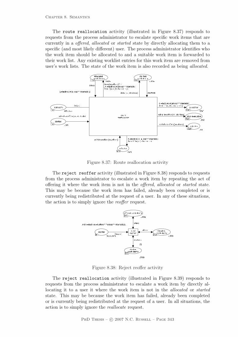
Chapter 8. Semantics
The route reallocation activity (illustrated in Figure 8.37) responds torequests from the process administrator to escalate specific work items that arecurrently in a offered, allocated or started state by directly allocating them to aspecific (and most likely different) user. The process administrator identifies whothe work item should be allocated to and a suitable work item is forwarded totheir work list. Any existing worklist entries for this work item are removed fromuser’s work lists. The state of the work item is also recorded as being allocated.
����� ������ � �� ��� ���
� �� � � ��� ��� �������� � ���� �� �� ��� ������������� ����� ��� ������ � ��� ���� ������ � ���� �� �� ��� ������������� ������ �� ����
������ ���� ��� �������� ���
� �������� ����!� ����� ������ ��"�� � ���� ������ ����� ����� ��� ��� "��� ������ ���
�� ������ ����!� ���
����!� ����!�
�!������ �����
�!�
���� �� �������� � �� ���� ������ ������ ���� �� �� ��� ������ ������ �� �������� � �� ��� ���
�� ���� �� �������� � �� ���� ������ � ���� �� �� ��� ������������� ������ �� ����
Figure 8.37: Route reallocation activity
The reject reoffer activity (illustrated in Figure 8.38) responds to requestsfrom the process administrator to escalate a work item by repeating the act ofoffering it where the work item is not in the offered, allocated or started state.This may be because the work item has failed, already been completed or iscurrently being redistributed at the request of a user. In any of these situations,the action is to simply ignore the reoffer request.
���� �� � �������� ����� � ��� ������������ ����� � ���� ��� � � ���� ����� ���������� ����������� �� ���� �������� ���� � ����������� �������� ������� ������� �������� ������������ ��� ���������� ��� ������
Figure 8.38: Reject reoffer activity
The reject reallocation activity (illustrated in Figure 8.39) responds torequests from the process administrator to escalate a work item by directly al-locating it to a user it where the work item is not in the allocated or startedstate. This may be because the work item has failed, already been completedor is currently being redistributed at the request of a user. In all situations, theaction is to simply ignore the reallocate request.
PhD Thesis – c© 2007 N.C. Russell – Page 343
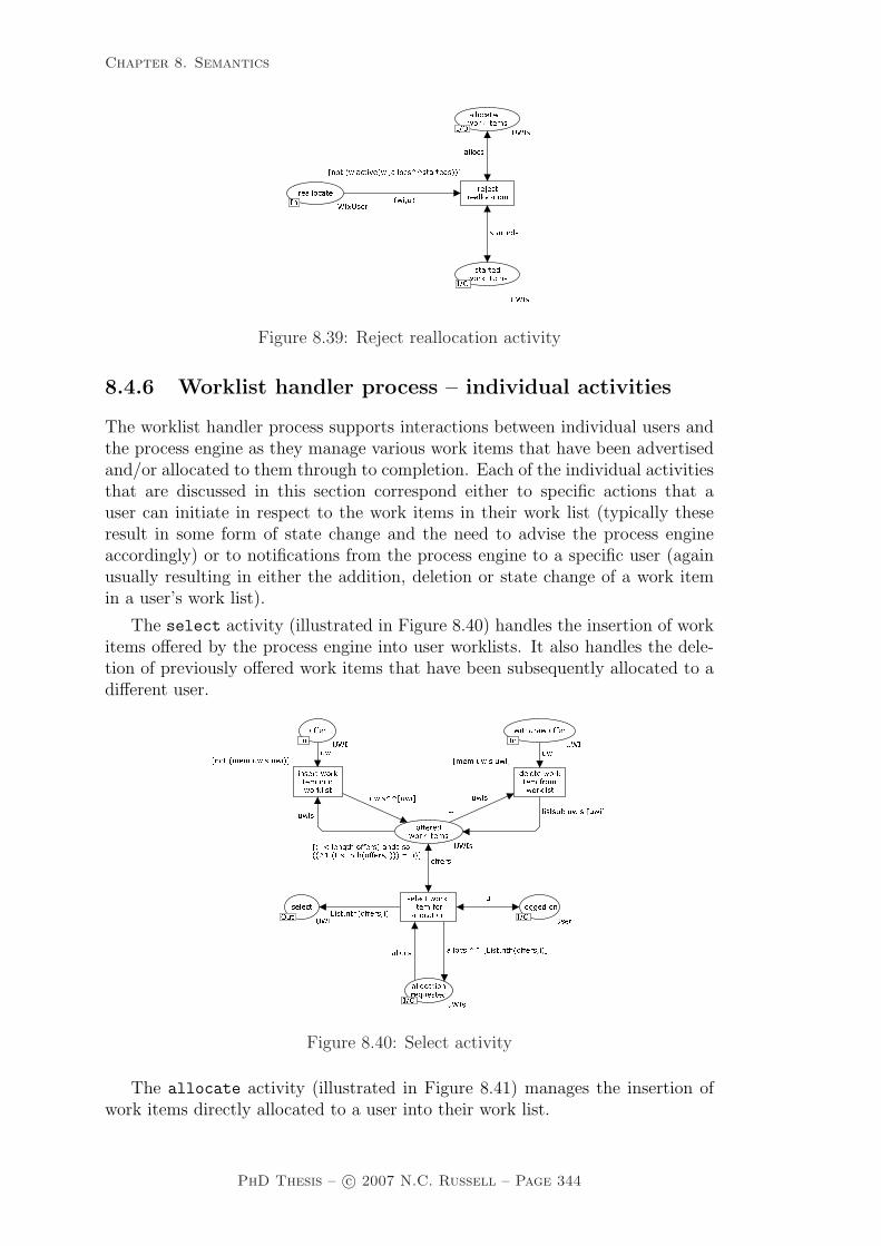
Chapter 8. Semantics
� ������� �� ��� �� ��� � ��� � ������ ������� �� ���� �� �� ��� ������������ ��� � ������ ����� �� ����� ����� � ������ �� ����� � ��� �� ����� �� ����� ���������
���
Figure 8.39: Reject reallocation activity
8.4.6 Worklist handler process – individual activities
The worklist handler process supports interactions between individual users andthe process engine as they manage various work items that have been advertisedand/or allocated to them through to completion. Each of the individual activitiesthat are discussed in this section correspond either to specific actions that auser can initiate in respect to the work items in their work list (typically theseresult in some form of state change and the need to advise the process engineaccordingly) or to notifications from the process engine to a specific user (againusually resulting in either the addition, deletion or state change of a work itemin a user’s work list).
The select activity (illustrated in Figure 8.40) handles the insertion of workitems offered by the process engine into user worklists. It also handles the dele-tion of previously offered work items that have been subsequently allocated to adifferent user.
� ��������� �� ������ �� � ��� �� � �
� ����� �� ��� �������� ��� ���� �
��� �������� ��� ��� ���� ��� � ��
�� ��� ������� ���� ����� ��� �� � ����� ���� ��� ���� ������� ���� �������� ��� ���� � ���� ��� ������� � ���������� ���� �� � ������ � ������� ���������� �� ����� �� � ��� ���� ��� !�
� ����� �����"�����#$ !�������� ���#$ ���
� ��� ��� ���� ��� !��� ���$ !�
���� ������� ���� � !��$
��
�#$�#$
��
Figure 8.40: Select activity
The allocate activity (illustrated in Figure 8.41) manages the insertion ofwork items directly allocated to a user into their work list.
PhD Thesis – c© 2007 N.C. Russell – Page 344

Chapter 8. Semantics
�� � �� ������� ���� ��� ����� � ����� � ��� � ���� ���� ���� ������ ����������� �������
��Figure 8.41: Allocate activity
The start activity (illustrated in Figure 8.42) provides the ability for a userto commence execution of a work item that has been allocated to them. In orderto start it, they must be logged in, have the choose privilege which allows themto select the next work item that they will execute and either not be currentlyexecuting any other work items or have the concurrent privilege allowing themto execute multiple work items at the same time.
���������� ���������� � � ������ ��� ������ ���� ������ ��
� � ����� ���� ������� ���
��� ��� � ������� ���������� � � ���� ��� ��� ������������� ��� ��� � ��� �� ���������������� � �� ������ ���������� ��� ��� � ��� �� ���������������� ��� �������� �������� ������ ������ � ���� ��� ����������� ��� ������������� � �� ������ ��������� ��� �������������� ��� ���� �������� ���� � ��� � ���� ������
��� � �������� ����� ��� ��� ����� ����
��� ����� ��������� ���� �� ���� ������� ��!�� �"#�� � ��#� �"#
� � �� �����$�����#%! �"#�
���� �������#%! ������ ��������#%! �"#�#%! #%!
#%!#� !��
���� ����
Figure 8.42: Start activity
The immediate start activity (illustrated in Figure 8.43) allows work itemsto be directly inserted in a user‘s worklist by the process engine with a currentlyexecuting status. As with the start activity, this is only possible if the user isnot currently executing any other work items or has the concurrent privilege.
�� �� �������� �� �� ��� ����� �� ���� �� ���� ���� �� �� �� ����� � �� ���� ������ ������������������� � �� ������ � ������ ������������������� �� ��������� �������� ��� ���� � ���� � ��� ����� ��������������� �������������� ���� ������ �!������� � ���� ���� �!���
�� ���������
Figure 8.43: Immediate start activity
At the request of the process engine, the halt instance activity (illustratedin Figure 8.44) immediately removes a specified work item from a user’s worklist.
PhD Thesis – c© 2007 N.C. Russell – Page 345
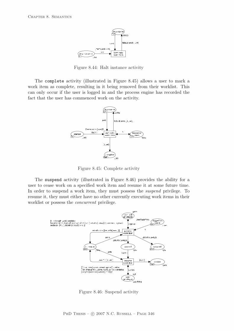
Chapter 8. Semantics
���� ������� �� �� ��� ���� � � ��� ���� �������� �� �� �� �� ��� ����� �������� ���� ����� ��������
Figure 8.44: Halt instance activity
The complete activity (illustrated in Figure 8.45) allows a user to mark awork item as complete, resulting in it being removed from their worklist. Thiscan only occur if the user is logged in and the process engine has recorded thefact that the user has commenced work on the activity.
������� �� �� ���� ����� � ��� ��� �� �� ������� �� ���������� �� ��� ����� ������ ��� � ��������� ���
�� �� � ������� ����� ���� ��������� ��� ����
������
��Figure 8.45: Complete activity
The suspend activity (illustrated in Figure 8.46) provides the ability for auser to cease work on a specified work item and resume it at some future time.In order to suspend a work item, they must possess the suspend privilege. Toresume it, they must either have no other currently executing work items in theirworklist or possess the concurrent privilege.
���������������� ���� ���� � �������� ��� �������
�� �������� ��� ���� ������ ������ � ����� ��� �� ����� � �������� ���� ������������ ��������� ����� ������ � �� ��� �� ��� � �� ������������ ��� ����� � �������� ���� ��� ��� ����� � ����� ��� ����������� ����������� �� ��� ��� ����� � �������� ��� � ���
��� ����� ������ � ! ���!����
��� � �������� ������ � "! ���"���!����������#�� $%������ $%������ � �����%&# �������� �#�� $%� ��������%&# $%�%&# #��
%&##������������ ���'� '���� ���������� � �� ���� �� ��������� ���'� '� ��� ���������� � �� ������ ��� ��������� ����� ���� � (����
Figure 8.46: Suspend activity
PhD Thesis – c© 2007 N.C. Russell – Page 346

Chapter 8. Semantics
The skip activity (illustrated in Figure 8.47) provides the user with the optionto skip a work item that is currently allocated to them. This means it transitionsfrom a status of allocated to one of completed. They can only do this if they havethe skip privilege.
�������������� � �� ���� � ���� ��� ��� � ���������� ������ � �� ��� � ��� � �� ������� ����� � ���� ��� ���� � �� � �� ������������ ��� ��� ��� ����� � ���� ��� ��������������������
��� ����� ������ �� !���� ���!����"��������#�� �$%��&������%'# �$%� ������ � �����%'# ����%'#%'#
#������ � ���� ��� ��Figure 8.47: Skip activity
The delegate activity (illustrated in Figure 8.48) allows a user to pass a workitem currently allocated to them to another user. They can only do this if theyhave the delegate privilege and the process engine has recorded the fact that thework item is allocated to them.
������ �� ��
���� �� � ��� � �����
�� ��� � �� ��������� ���������� � ���� ���� ��������� ����� �� ��� ��� �� ������ ������������ �� ���� ��� ������ ������� ��� �� ����� ����� �� !��� ��!�����"���#� ���
� ��$���� ������#���
���
Figure 8.48: Delegate activity
The abort activity (illustrated in Figure 8.49) operates at the request of theprocess engine and removes a work item currently allocated to a user from theirworklist. If they have also requested that its execution be started, this request isalso removed.
�� � �� �� ������� �� �� ������ ��� �� �� ��� ��� �� �� ��� � �� ��� ��� ���� ��� �� �� ���� ���������
Figure 8.49: Abort activity
PhD Thesis – c© 2007 N.C. Russell – Page 347
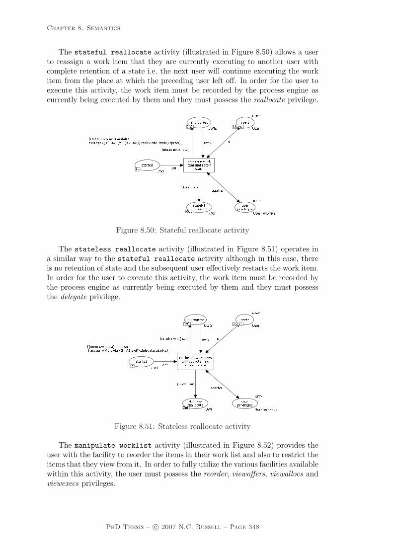
Chapter 8. Semantics
The stateful reallocate activity (illustrated in Figure 8.50) allows a userto reassign a work item that they are currently executing to another user withcomplete retention of a state i.e. the next user will continue executing the workitem from the place at which the preceding user left off. In order for the user toexecute this activity, the work item must be recorded by the process engine ascurrently being executed by them and they must possess the reallocate privilege.
����� �� �� ����� ������ �� �� ��� ���� � ��� ���� ����� ���������� ��� �������������� �� �� �� ���� ��������� ����� �� ��� ��� �� ���� �� �������������������
������� �� �������� �� ����� � �!�� ��"#���"���#������ ��� � ��
��� ����� ���� ��� �� �! ��� $� �� � $� ���� �
���Figure 8.50: Stateful reallocate activity
The stateless reallocate activity (illustrated in Figure 8.51) operates ina similar way to the stateful reallocate activity although in this case, thereis no retention of state and the subsequent user effectively restarts the work item.In order for the user to execute this activity, the work item must be recorded bythe process engine as currently being executed by them and they must possessthe delegate privilege.
����� �� ����� ����� ��� ��� � �����
�� ���� ������ ���� ���� ���� ��� ����������� ��������� � �� �� ���� ������������ ���� ��� ��� �� ������ ������������ �� ����� �������� ���
� ����� ��������� ��� ������ ����� ����� �� !��� ��!���
�� �������"� ����"� �����
��Figure 8.51: Stateless reallocate activity
The manipulate worklist activity (illustrated in Figure 8.52) provides theuser with the facility to reorder the items in their work list and also to restrict theitems that they view from it. In order to fully utilize the various facilities availablewithin this activity, the user must possess the reorder, viewoffers, viewallocs andviewexecs privileges.
PhD Thesis – c© 2007 N.C. Russell – Page 348
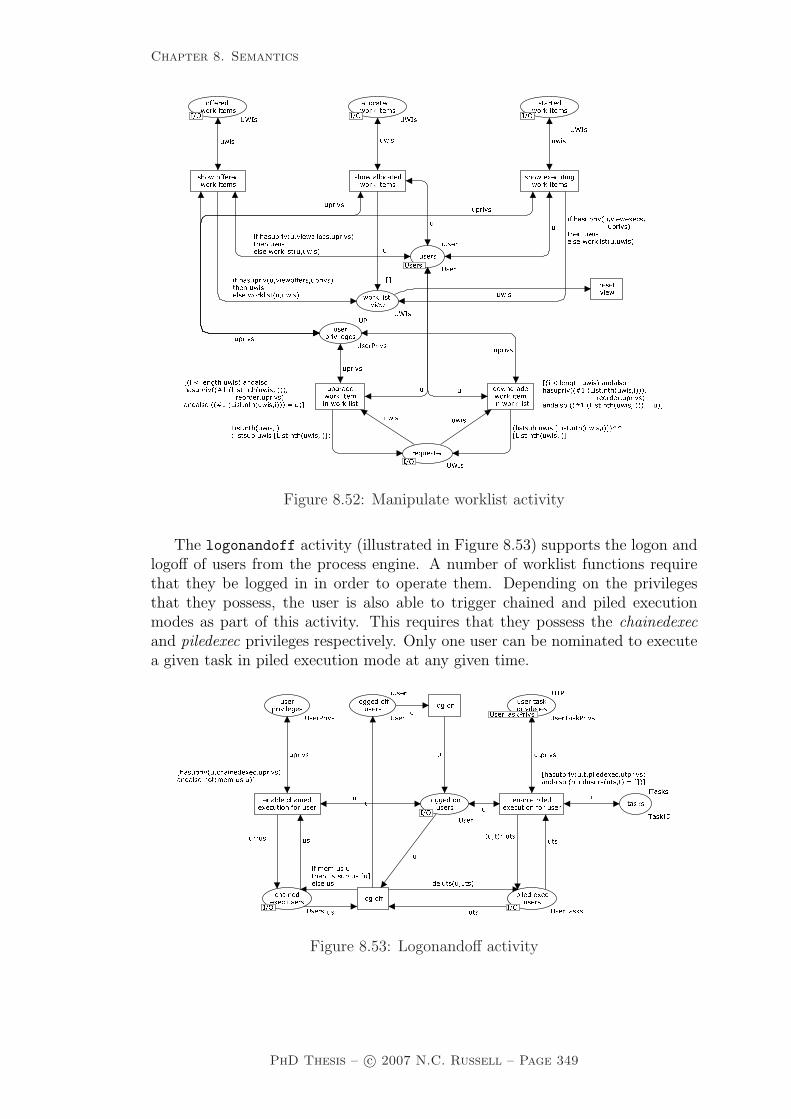
Chapter 8. Semantics
�
�� �������� �
�� ��
������ ������������
�� ��������
�� ������ � ������ � �� ��������� ������ � ����� ����
��������������
����
�� ����
��� ���� ��� ������� � ��� � � ����� � ��������� ����� ����� � ������������ � ����� ����� � ��
���� ��� � �� �� ���������� �� �������� ���� ��� ���������� �� �� �� �� ������� ����� ��� � ��� � � �������� ���� ������������� �� ���� �� ������� ����� ����� ����� ������� ������� � ������� ��� ������������ � ������� ��� ��� ��� � �� ��� ���� ����������� ��!" �#�� $� ������� ������� �� ������������� ��� ��!" �#�� $� ���� ��� ���� % �����&�� ����������� �� ��
� �������� ���� ��� ������������� �� �� �� �� ������� ����� ��� �� � ������ ��' �� �� �#�� $� ���� ��� ����((�#�� $� ���� ��� ���#�� $� ���� ��� �� ))���� ��' ���� �#�� $� ������� ������� ��� � �� ��� ���� ����������� ��!" �#�� $� ������� ��������� ������������� ��� ��!" �#�� $� ���� ��� ���� % ���
Figure 8.52: Manipulate worklist activity
The logonandoff activity (illustrated in Figure 8.53) supports the logon andlogoff of users from the process engine. A number of worklist functions requirethat they be logged in in order to operate them. Depending on the privilegesthat they possess, the user is also able to trigger chained and piled executionmodes as part of this activity. This requires that they possess the chainedexecand piledexec privileges respectively. Only one user can be nominated to executea given task in piled execution mode at any given time.
������ ���� �������
������������� ����
��
����� �� � �
���
������ ���������� ��� �� ��� ������ ��� ���������� ��� �� ��� ��� ��
��� ������ �� ������������
��� ������ ����������������� ������������������ �� ������ �������
���� ������� ���� ����������� �������� ��� ���� ���������� ���������
������ ������ � ���� ������
��� ���
������������� ����� ����� ������� �� �!� ��� ����
������ ������ ������������������ ��� ��� ������ ��! ��� ������� ����� ������������������� ��� �������� � ������� " !�!
Figure 8.53: Logonandoff activity
PhD Thesis – c© 2007 N.C. Russell – Page 349

Chapter 8. Semantics
8.4.7 Interrupt processing – individual activities
Interrupt processing allows the normal progress of a work item to be varied whererequired as a result of a cancel, force-fail or force-complete request being receivedfrom an external party. There are three main components of which it is comprised:the cancel work item, complete work item and force fail work item pro-cesses. The individual activities for each of these are shown below.
The cancel work item process provides facilities to handle a cancellationrequest initiated from outside the work distribution process. It enables a workitem currently being processed (and in any other state than completed) to beremoved from both the work distribution and worklist handler processes. Noconfirmation is given regarding work item cancellation.
���� ������ �������� ��� ��
�������� �� � �� ��� �� ��� ����
� ���� ���� �� ��� �
� ���������� �� �� ���� ������ � ��������� �� �� ��� ������� �
�� �� ��� ������ ����� � ��� ��� �� ���� ����� ���� ��� ������� �� �� ���� ������ ��� ����
���� ��
� ����� �� �� ��� ��� �������� � ��� ��� �� ������ ��� ���� ��� ������� �� �� ������ ���� ��� ������ � ��� ��� �� ��� ������ ���� ���������� �� �� ��� ������� ��� ����
�� ���� �� �� ��� ���� �����
����� ��� �� ��������� ������� �� �� ��� �� ����� � � ����� ��������������� ���������� � �
����� �� �� ��������� ����� ��� ��� �� ������ ����� �������������� � �� ����� �������� ��� � �� ��� ���� �� �� ��� �� ����� � ���
������������ ������� ���� �� ��������� ������� ��� ����!������ ������ � � �� ��� ������ ���
�� ����� ���� ������� ������� ��� �� ����� �� ������� ���� ��
���� ������� ������� ���
� ����������� ������� ���
���� ������� �� ����"����� ���� ������� ������� ������
�����
���
�������
������
���
Figure 8.54: Cancel work item process
The complete work item process provides facilities to handle a force-completerequest initiated from outside the work distribution process. It enables a workitem currently being processed (and in any other state than completed) to bemarked as having completed and for it to be removed from both the work distri-bution and worklist handler processes. If the request is successful, the work itemcompletion is indicated via a token in the completed work items place which ispassed back to the high-level process execution process (i.e. as illustrated inFigure 8.1).
PhD Thesis – c© 2007 N.C. Russell – Page 350

Chapter 8. Semantics
���
� ��� ��
���������� �� �� ������ �� ����
����� ��� � ���� � ���� ��
� ���� ��� ��� �
� ��� ������ �� �� ����� ��� � �� ������� �� �� ��� ����� � � �� ��� ����� �� ��� ��
� ����� �� ��� ��� �����
��� ��� �� ��� ����� ���
�������� ��� ��������� ������ ��� ���� � ���� � �������������������� ��������� � ��
������ ��� ��������� ����� ���� �� �� ����� ����� ������������� � � ����� ������� �� � � �� ��� �� � ���� � ���� � � �
��� ��������� ������� ��� ���!����� �� ������ � ��� ����� ������ ���
��� ���� ��� ����� ������������ ������� ���
���������� ����� �� �������� ������ ��
��� ����� ������� ���
� ���������� ������� ���
� ��������� ���� ���"����� ����� ������ ������� ������
������
���
���
��������
����
������
�� � ���� �� �� ����� �� � ��� ��� ������ �� �� ����� �� �� ���#�� � ���� �� �� ����� ����� ������������� �������� �� �� � ���� � ���� �� �� ��� ����� ���� ��������� �� �� ��� ����� �� ���#�� � ���� �� �� ����� ��� ���� ��������� �� �� ����� ��� �� ���#
Figure 8.55: Complete work item process
The fail work item process provides facilities to handle a force-fail requestinitiated from outside the work distribution process. It enables a work itemcurrently being processed (and in any other state than completed) to be markedas having failed and for it to be removed from both the work distribution andworklist handler processes. If the request is successful, the work item failure isindicated via a token in the failed work items place which is passed back tothe high-level process execution process.
The scale of the semantic model illustrates the overall complexity of newYAWL.Running to 55 distinct pages and encompassing over 480 places, 138 transitionsand over 1500 lines of ML code, it is only through this form of interactive mod-elling (that the CPN Tools environment supports) that formal specifications ofthis size and complexity can be developed in a tractable manner. The completeCPN model is available from http://www.yawl-system.com/newYAWL. There isalso an associated newYAWL technical report which includes a working example[RHEA07].
PhD Thesis – c© 2007 N.C. Russell – Page 351

Chapter 8. Semantics
���
�������� �� �� ��
���� ���� � � � �
� �� ��� �
� �� ��� ��� �� �� ����� ������ �� ��� ��� �� �� ��� �� ���� �
� �� ��� �� ��� ��� ��� ��
� �� �� � �� ��� ��� �� ����� � ���� ��� �� ��� �� ��� � ��� �� ��� ��� �� �� ��� �� ���� ��� �����
��� ���� � �� ��� ����� �����
�� �� �� ��� ������� �� �������� �� � ���� � ������ � ���� �� ���� ������ �� ����������� ���
�� �� ��� ������� �� ����
��� ������� �� �������� �������� ���� �� ������ � ��� ����� � ���� ���
��� ����� ����� ������� ����� ���� �� �������� ��
�� ��� �� ������ �� �� ������� � ���� ���
��� ��� �� �������� ����
� �� ����� �� �������� ����
� ����� ��� ���� �����!������� ������ ���� �� �������� �������
���������
���
��������
����
������
�� � ���� ��� �� �� ��� ��� � ��� �� ��� ��� �� �� �� ��� ���� ��� ������� � ���� ��� �� ����� ����� ���� �� ��� ��� �� �� ����� ������ ��� ������� � ���� ��� �� �� ��� ��""� �� ��""����������� #$� � � ��� �����
������ ��� �� �� ��� ��""� �� ��""�������� �� ���� � �������� ��� �� ��� ���� ��� ���� � ������ � ����
� �������� �����Figure 8.56: Fail work item process
8.5 Summary
This chapter has presented the semantic model for the newYAWL reference lan-guage. This model provides a precise operational definition of all newYAWLconstructs. It also has the additional advantage (as a consequence of its CP-netfoundations) that it is possible to directly execute a newYAWL business processmodel in the CPN Tools environment. The development of this model demon-strates that the patterns identified in Part One of this thesis provide a suitablebasis for establishing the fundamental requirements for PAIS and that these dis-crete concepts can be suitably integrated. More significantly, the newYAWLsemantic model confirms that it is possible to formally define a comprehensiveconceptual foundation for PAIS that is also able to be directly and unambiguouslyenacted.
In the next chapter of the thesis, the capabilities of the newYAWL referencelanguage are comprehensively evaluated from a patterns perspective. In doing so,it is possible to compare the capabilities of newYAWL against other PAIS andbusiness process modelling languages.
PhD Thesis – c© 2007 N.C. Russell – Page 352

Chapter 9. Pattern Support in newYAWL
Chapter 9
Pattern Support in newYAWL
As a benchmark of the capabilities of newYAWL, this chapter presents the re-sults of a patterns-based evaluation of the language using the control-flow, data,resource and exception patterns presented in Part One of the thesis. For compar-ative purposes, this evaluation is contrasted with one for YAWL. Although thereis a formal definition for YAWL, it is limited to the control-flow perspective. Forthis reason, the evaluation results in this section are based on the latest versionof the YAWL System (Beta 8). The newYAWL results are based on the capabil-ities demonstrated by the abstract syntax and the semantic models presented inChapters 7 and 8 respectively. Subsequent sections in this chapter present the re-sults of pattern evaluations in four perspectives: control-flow, data, resource andexception handling. Full details of the control-flow, data and resource patternsrealization in newYAWL are included in Appendix A.
9.1 Control-flow perspective
Table 9.1 identifies the extent of support by YAWL and newYAWL for the control-flow patterns. YAWL supports 19 of the 20 original control-flow patterns. Theonly omission being Implicit Termination which, although being the preferredmethod of process termination, is not fully implemented in the YAWL system. Itfares less well in terms of support for the new control-flow patterns. The avail-ability of the cancellation region construct allows YAWL to support the CancelRegion, Cancel MI Task and Cancelling Discriminator patterns. Similarly, theavailability of a multiple instance task construct ensures the Static Partial Joinfor MIs and the Static Cancelling Join for MIs patterns are supported. Con-siderable work [WEAH05] has gone into OR-join handling in YAWL, hence theAcyclic and General Synchronizing Merge are supported. Finally the Petri netfoundation for YAWL provide a means of supporting the Critical Section andInterleaved Routing patterns. None of the other new control-flow patterns aresupported.
In contrast, newYAWL supports 42 of the 43 patterns. The only omissionis the Implicit Termination pattern which is not supported as the terminationsemantics of newYAWL are based on the identification of a single defined end nodefor processes. When the thread of control reaches the end node in a newYAWL
PhD Thesis – c© 2007 N.C. Russell – Page 353

Chapter 9. Pattern Support in newYAWL
Nr Pattern YAW
L
new
YAW
L
Nr Pattern YAW
L
new
YAW
L
Basic Control New Control-Flow Patterns1 Sequence + + 21 Structured Loop – +2 Parallel Split + + 22 Recursion – +3 Synchronization + + 23 Transient Trigger – +4 Exclusive Choice + + 23 Persistent Trigger – +5 Simple Merge + + 25 Cancel Region + +
Adv. Branching & Synchronization 26 Cancel MI Activity + +6 Multiple Choice + + 27 Complete MI Activity – +7 Structured Synchronizing Merge + + 28 Blocking Discriminator – +8 Multiple Merge + + 29 Cancelling Discriminator + +9 Structured Discriminator + + 30 Structured Partial Join – +
Structural 31 Blocking Partial Join – +10 Arbitrary Cycles + + 32 Cancelling Partial Join – +11 Implicit Termination +/– – 33 Generalized AND-Join + +
Multiple Instance 34 Static Partial Join for MIs + +12 MI without Synchronization + + 35 Static Canc. Part. Join for MIs + +13 MI with a priori D/T Knowl. + + 36 Dynamic Partial Join for MIs – +14 MI with a priori R/T Knowl. + + 37 Acyclic Synchronizing Merge + +15 MI without a priori R/T Knowl. + + 38 General Synchronizing Merge + +
State-based 39 Critical Section + +16 Deferred Choice + + 40 Interleaved Routing + +17 Interleaved Parallel Routing + + 41 Thread Merge – +18 Milestone + + 42 Thread Split – +
Cancellation 43 Explicit Termination – +19 Cancel Activity + +20 Cancel Case + +
Table 9.1: Support for control-flow patterns in Original YAWL vs newYAWL
process instance, it is deemed to be complete and no further work is possible.Thus it achieves a full support rating for the Explicit Termination pattern whichis a distinction from previous versions of the YAWL System which were based onImplicit Termination.
9.2 Data perspective
Table 9.2 illustrates data pattern support in YAWL and newYAWL. The datamodel in YAWL is based on the use of net variables which are passed to and fromtasks using XQuery statements. These can be used for data passing to all formsof task hence the Block Data and Multiple Instance Data patterns are directlysupported together with the various Data Interaction patterns relevant to theseconstructs. The use of XQuery for data passing ensures the Data Transfer byValue – Incoming and Outgoing patterns are also supported together with thecorresponding Data Transformation patterns. There is also support for Data-based Routing.
newYAWL markedly improves on this range of capabilities and supports allbut two of the patterns. One of the two remaining patterns – Data Transfer byReference – Locked – receives a partial support rating. This is a consequence ofthe value-based interaction strategy that newYAWL employs for data passing.newYAWL does provide locking facilities for data elements, hence it is possibleto prevent concurrent use of a nominated data element thus achieving the same
PhD Thesis – c© 2007 N.C. Russell – Page 354

Chapter 9. Pattern Support in newYAWL
Nr Pattern YAW
L
new
YAW
L
Nr Pattern YAW
L
new
YAW
L
Data Visibility Data Interaction (Ext.) (cont.)1 Task Data – + 21 Env. to Case – Push-Oriented – +2 Block Data + + 22 Case to Env. – Pull-Oriented – +3 Scope Data – + 23 Process to Env. – Push-Orient. – +4 Multiple Instance Data + + 24 Env. to Process – Pull-Orient. – +5 Case Data – + 25 Env. to Process – Push-Orient. – +6 Folder Data – + 26 Process to Env. – Pull-Orient. – +7 Global Data – + Data Transfer8 Environment Data – + 27 by Value Incoming + +
Data Interaction (Internal) 28 by Value Outgoing + +9 between Tasks + + 29 Copy In/Copy Out – +10 Block Task to Subproc. Decomp. + + 30 by Reference – Unlocked – –11 Subproc. Decomp. to Block Task + + 31 by Reference – Locked – +/–12 to Multiple Instance Task + + 32 Data Transformation – Input + +13 from Multiple Instance Task + + 33 Data Transformation – Output + +14 Case to Case – + Data-based Routing
Data Interaction (External) 34 Task Precondition – Data Exist. – +15 Task to Env. – Push-Oriented – + 35 Task Precondition – Data Val. – +16 Env. to Task – Pull-Oriented – + 36 Task Postcondition – Data Exist. – +17 Env. to Task – Push-Oriented – + 37 Task Postcondition – Data Val. – +18 Task to Env. – Pull-Oriented – + 38 Event-based Task Trigger – +19 Case to Env. – Push-Oriented – + 39 Data-based Task Trigger – +20 Env. to Case – Pull-Oriented – + 40 Data-based Routing + +
Table 9.2: Support for data patterns in Original YAWL vs newYAWL
operational effect as required for support of this pattern however as it is notdirectly implemented in this form, it only achieves a partial support rating.
9.3 Resource perspective
Table 9.3 illustrates the extent of resource pattern support by the two offerings.YAWL provides relatively minimal consideration of this perspective supportingonly 8 of the 43 patterns.
In contrast, newYAWL supports 38 of the 43 resource patterns. The five thatare not supported are:
– Case Handling – as this implies that complete process instances are allocatedto users rather than individual work items as is the case in the majority ofcurrent PAIS;
– Early Distribution – as work items in newYAWL can only be allocated to usersonce they have been enabled;
– Pre-Do – as work items can only be executed at the time they are enabled andcannot be allocated to a resource prior to this time;
– Redo – as work items cannot be re-allocated to a user at some time after theirexecution has been completed; and
– Additional Resource – as work items are only ever undertaken by a singleresource in newYAWL and there is no provision for the additional involvementof non-human resources.
PhD Thesis – c© 2007 N.C. Russell – Page 355

Chapter 9. Pattern Support in newYAWL
Nr Pattern YAW
L
new
YAW
L
Nr Pattern YAW
L
new
YAW
L
Creation Patterns Pull Patterns (cont.)1 Direct Distribution + + 24 System-Determ. Wk Queue Cont. – +2 Role-Based Distribution + + 25 Res.-Determ. Wk Queue Cont. – +3 Deferred Distribution – + 26 Selection Autonomy – +4 Authorization – + Detour Patterns5 Separation of Duties – + 27 Delegation – +6 Case Handling – – 28 Escalation – +7 Retain Familiar – + 29 Deallocation – +8 Capability-Based Distribution – + 30 Stateful Reallocation – +9 History-Based Distribution – + 31 Stateless Reallocation – +10 Organizational Distribution – + 32 Suspension/Resumption – +11 Automatic Execution + + 33 Skip – +
Push Patterns 34 Redo – –12 Distrib. by Offer - Single Res. + + 35 Pre-Do – –13 Distrib. by Offer - Multiple Res. + + Auto-Start Patterns14 Distrib. by Allocation - Single Res. – + 36 Commencement on Creation – +15 Random Allocation – + 37 Creation on Allocation – +16 Round Robin Allocation – + 38 Piled Execution – +17 Shortest Queue – + 39 Chained Execution – +18 Early Distribution – – Visibility Patterns19 Distribution on Enablement + + 40 Conf. Unalloc. Work Item Visib. – +20 Late Distribution – + 41 Conf. Alloc. Work Item Visib. – +
Pull Patterns Multiple Resource Patterns21 Res.-Init. Allocation + + 42 Simultaneous Execution + +22 Res.-Init. Exec. - Alloc. Wk Items + + 43 Additional Resource – –23 Res.-Init. Exec. - Offer. Wk Items – +
Table 9.3: Support for resource patterns in Original YAWL vs newYAWL
9.4 Exception handling perspective
Table 9.4 illustrates the extent of exception pattern support by YAWL andnewYAWL. Whilst the graphical exception handling language is supported inboth offerings, the rollback primitive is not. Nonetheless, the breadth of supportprovided for exception handling is extensive, especially when compared with thecapabilities offered by other PAIS in the area, e.g. as illustrated in Table 5.2.
9.5 Summary
This chapter has illustrated the range of capabilities provided by newYAWL inthe control-flow, data, resource and exception handling perspectives through apatterns-based evaluation. This approach to language assessment affords an ob-jective, technology-independent means of evaluating language capabilities. Theresults of this evaluation clearly demonstrate that newYAWL embraces a markedlygreater range of concepts than any other PAIS or business process modelling lan-guage that has been examined in Part One of this thesis. The breadth of itscapabilities are underscored by the fact that it directly supports 118 of the 126patterns that that have been identified for the control-flow, data and resource per-spectives. Similarly, it supports a far wider range of exception handling strategiesthan have been observed for any other, offering support for 89 of the 108 strategiesthat have been identified.
PhD Thesis – c© 2007 N.C. Russell – Page 356

Chapter 9. Pattern Support in newYAWL
Work ItemFailure
Work ItemDeadline
ResourceUnavailable
ExternalTrigger
ConstraintViolation
OFF-CWC-NIL OCO-CWC-NIL ORO-CWC-NIL OCO-CWC-NIL SCE-CWC-NILOFF-CWC-COM ORO-CWC-NIL OFF-CWC-NIL OFF-CWC-NIL SRS-CWC-NILOFC-CWC-NIL OFF-CWC-NIL OFF-RCC-NIL OFF-RCC-NIL SRS-CWC-COMOFC-CWC-COM OFF-RCC-NIL OFC-CWC-NIL OFC-CWC-NIL SFF-CWC-NILAFF-CWC-NIL OFC-CWC-NIL ARO-CWC-NIL ACA-CWC-NIL SFF-CWC-COMAFF-CWC-COM ACA-CWC-NIL ARA-CWC-NIL AFF-CWC-NIL SFF-RCC-NILAFC-CWC-NIL ARA-CWC-NIL AFF-CWC-NIL AFF-RCC-NIL SFF-RCC-COMAFC-CWC-COM ARO-CWC-NIL AFF-RCC-NIL AFC-CWC-NIL SFF-RAC-NILSRS-CWC-NIL AFF-CWC-NIL AFC-CWC-NIL SCE-CWC-NIL SFC-CWC-NILSRS-CWC-COM AFF-RCC-NIL SRA-CWC-NIL SRS-CWC-NIL SFC-CWC-COMSFF-CWC-NIL AFC-CWC-NIL SRA-CWC-COM SRS-CWC-COMSFF-CWC-COM SCE-CWC-NIL SRO-CWC-NIL SFF-CWC-NILSFF-RCC-NIL SCE-CWC-COM SRO-CWC-COM SFF-CWC-COMSFF-RCC-COM SRS-CWC-NIL SFF-CWC-NIL SFF-RCC-NILSFC-CWC-NIL SRS-CWC-COM SFF-CWC-COM SFF-RCC-COMSFC-CWC-COM SRA-CWC-NIL SFF-RCC-NIL SFF-RAC-NIL
SRA-CWC-COM SFF-RCC-COM SFC-CWC-NILSRO-CWC-NIL SFF-RAC-NIL SFC-CWC-COMSRO-CWC-COM SFC-CWC-NILSFF-CWC-NIL SFC-CWC-COMSFF-CWC-COMSFF-RCC-NILSFF-RCC-COMSFC-CWC-NILSFC-CWC-COM
Table 9.4: Exceptions patterns support in YAWL and newYAWL
PhD Thesis – c© 2007 N.C. Russell – Page 357

Chapter 10. Epilogue
Chapter 10
Epilogue
The objective of this thesis (as originally stated in Section 1.2) was to establisha comprehensive definition of the fundamental components of a business processand the manner in which they interrelate. This definition was to be based on aformal foundation in order to remove any potential for ambiguity in the inter-pretation of these concepts. It was also required to facilitate the execution of abusiness process described in terms of these constructs in a deterministic way.
This goal has been satisfied at two levels. First, the fundamental componentsof business processes have been informally defined through the identification of126 patterns which describe the core characteristics of business processes in thecontrol-flow, data and resource perspectives, together with a graphical exceptionhandling language which describes how deviations from expected behaviour acrossall of these perspectives should be handled. Second, a comprehensive businessprocess language – newYAWL – has been formally defined which encompassesthese patterns and describes their operation in an integrated manner.
At the beginning of this research, five solution criteria were defined as a meansof evaluating the effectiveness of the solution ultimately reached to the researchproblem. We now revisit each of these criteria.
Formality This requirement has been met through the development of an ab-stract syntax and operational semantics for newYAWL. This provides the def-inition for a business process language that is based on the integration of thebroadest possible range of patterns that are relevant to PAIS. As the descrip-tion of the semantics of the language is formalized using CP-nets, it provides acomprehensive foundation for business processes that allows them to be capturedprecisely in a form that is suitable for further analysis using a wide range of wellestablished techniques.
Suitability The identification of the core constructs of business processes wasbased on an empirical survey of the control-flow, data and resource perspectives ofa wide variety of contemporary PAIS. This approach ensured that a comprehen-sive range of concepts were revealed and subsequently delineated as patterns. Asimilar approach was taken to the identification of exception handling primitivesand the subsequent development of a graphical language for specifying exceptionhandling strategies. One of the major uses of the patterns to date has been in
PhD Thesis – c© 2007 N.C. Russell – Page 358

Chapter 10. Epilogue
evaluating the capabilities of specific PAIS in a manner that allows for comparisonwith other offerings. There are a number of these evaluations contained withinthis thesis and elsewhere that give an insight into the suitability of existing offer-ings. They also provide a benchmark for the desirable range of capabilities that anewly developed PAIS should demonstrate. newYAWL embodies 118 of the pat-terns identified in this thesis thereby establishing its suitability for the purposesof capturing business processes. It provides particularly rich capabilities in thedata and resource perspectives, the breadth of which have not previously beendemonstrated by other PAIS. Finally through a detailed examination of excep-tion handling, it has been possible to establish a pattern-oriented approach todescribing the exception handling capabilities of distinct PAIS. This provides atechnologically independent means of assessing their capabilities in this area. Amajor consequence of this work, has been the development of a graphical languagefor describing exception handling strategies that is both independent of specificimplementation technologies and spans the control-flow, data and resource per-spectives described above.
Conceptuality There are two major advantages offered by the use of a patterns-based approach to eliciting the major concepts underpinning business processes.The first of these is that it tightly focuses the knowledge gathering activity en-suring that only concepts directly relevant to the business process domain areconsidered. The second is that each of the resultant patterns is described at aconceptual level and is independent of specific technological or implementation-related considerations. This is necessary in order to ensure that the pattern doesindeed generalize across a wide range of potential process design and enactmentenvironments. newYAWL is directly founded on the elicited patterns and doesnot assume any specific technological or operational characteristics of the ultimateexecution environment.
Enactability The ability to directly execute a business process model in a de-terministic manner without requiring the addition of further information is adesirable characteristic. A newYAWL business process model is capable of beingdirectly enacted. In order to do so, it is first transformed into a core newYAWLspecification using the transformations described in Chapter 7. It can then beexecuted and the operational semantics for this are described in Chapter 8 ofthe thesis. Moreover, as a consequence of the formalization approach chosen fornewYAWL in which the semantics are described using CP-nets, it is possible totake a candidate newYAWL specification represented as an initial marking of thenewYAWL semantic model and execute it in the CPN Tools environment.
Comprehensibility There are two facets to the issue of comprehensibility –ease of capture and ease of interpretation. The first of these is facilitated throughthe range of patterns embodied in newYAWL and the relatively direct correspon-dence between them and the constructs in the abstract syntax model. The secondfacet is more difficult to assess. There is a graphical syntax for the control-flowperspective of newYAWL and also for specifying exception handling strategies,thus users can gain a relatively quick understanding of process operation in theseperspectives. The data and resource perspectives do not have a graphical syntax
PhD Thesis – c© 2007 N.C. Russell – Page 359

Chapter 10. Epilogue
however there is a relatively close correspondence between the individual pat-terns in these areas and the various elements in the abstract syntax for theseperspectives which make their operation more intuitive. There is the opportu-nity to augment the newYAWL graphical syntax to cater for data and resourceconstructs at some future time (e.g. by including parameters, arc conditions andwork distribution directives).
Limitations
The patterns identified during in this thesis are intended to provide a compre-hensive basis for describing the desirable properties of PAIS and the constructson which they should be based. The process of identifying patterns was based ona comprehensive survey of the features and capabilities of a variety of contempo-rary workflow and case handling systems, business process modelling formalismsand execution languages. By providing a precise description of each pattern anddetailed context and evaluation criteria for each pattern, it is intended that eachpattern is documented in an objective format. Each of the patterns evaluationsdescribed in this thesis are based on these definitions were undertaken by theauthor in conjunction with at least one other party. Wherever possible, theseresults were cross-checked with a domain expert (usually either a staff member ofthe vendor or a member of a standards body in the case of modelling formalisms)in order to validate their correctness. On this basis, it is reasonably expectedthat the patterns evaluation activity is objective in nature and repeatable.
In terms of the approach taken to identifying specific patterns, two potentiallimitations are recognized:
1. The approach to identifying patterns is experiential in nature, hence it isinfluenced by the specific offerings on which the patterns survey is based.All of the patterns identified in this thesis are based on specific features,capabilities or constructs encountered in these offerings or on generaliza-tions or extensions of them. Moreover, the delineation of specific patternsis based on a subjective assessment of the capabilities of individual offer-ings. Therefore it is debatable whether this particular research activity isrepeatable.
2. The process of patterns identification is not a structured activity and it isnot clear when it is ultimately complete. Although it has not been possibleto identify any further meaningful patterns in the control-flow, data orresource perspectives as part of this thesis, it cannot be claimed that the126 patterns that have been identified represent the complete set of patternsrelevant to PAIS.
Contributions
In conclusion, the contributions of this thesis are fourfold:
1. A collection of 126 patterns identifying recurring concepts relevant to thecontrol-flow, data and resource perspectives of business processes;
PhD Thesis – c© 2007 N.C. Russell – Page 360

Chapter . Epilogue
2. A patterns-based classification framework for describing exception handlingcapabilities of PAIS;
3. A graphical, technology-independent language for defining exception han-dling strategies; and
4. newYAWL: A comprehensive, formally defined language for business pro-cess modelling and enactment.
It is anticipated that these deliverables will inform future research activitiesassociated with PAIS. The exception handling language has already been incor-porated into the YAWL open source software offering (release Beta 8) and itsimplementation is described at length elsewhere [AHEA07, Ada07].
PhD Thesis – c© 2007 N.C. Russell – Page 361

Appendix A. Patterns Realization in newYAWL
Appendix A
Patterns Realization innewYAWL
A.1 Control-flow patterns
Nr Pattern Representation in Abstract Syntax
1 Sequence Via an entry in the flow relation (t1, t2) ∈ Fwhere t1, t2 are tasks, i.e. t1, t2 ∈ T
2 Parallel Split Via an entry in the Split function for task twhere Split(t) = AND .
3 Synchronization Via an entry in the Join function for task twhere Join(t) = AND .
4 Exclusive Choice Via an entry in the Split function for the task twith which the pattern is associated whereSplit(t) = XOR. The evaluation sequence foreach outgoing arc from t is indicated by <t
XOR.Entries in the ArcCond function define the arcexpression for each outgoing branch from task t.Finally an entry in the Default functionDefault(t) denotes the default outgoing arc thatis taken if no arc condition evaluates positivelyfor task t.
5 Simple Merge Via an entry in the Join function for task twhere Join(t) = XOR.
6 Multi-Choice Via an entry in the Split function for the task twith which the pattern is associated whereSplit(t) = OR. Entries in the ArcCond functiondefine the arc expression for each outgoingbranch from task t. An entry in the Defaultfunction Default(t) denotes the default outgoingarc that is taken if no arc condition evaluatespositively for task t.
PhD Thesis – c© 2007 N.C. Russell – Page 362

Appendix A. Patterns Realization in newYAWL
Nr Pattern Representation in Abstract Syntax7 Structured
Synchronizing MergeVia an entry in the Join function for task twhere Join(t) = OR and the branches whichare inputs to t are structured in form.
8 Multi-Merge Via an entry in the Join function for task twhere Join(t) = XOR.
9 StructuredDiscriminator
Via an entry in the Join function for task twhere Join(t) = PJOIN, and a correspondingentry in the Thresh function where Thresh(t) =1. All input branches to t are structured inform.
10 Arbitrary Cycles There are no restrictions on the capture ofcycles in the flow relation F of a newYAWL-net.
11 Implicit Termination Not supported.12 Multiple Instances
withoutSynchronization
By encoding a structure of the form indicatedin Fig 2.15 in the flow relation F, where thecreate instances task is described as task t ∈ Ttogether with an entry in the Join functionsuch that Split(t) = AND to split the thread ofcontrol from the main branch. In the newbranch, there is another task tS ∈ T , that isassociated with an entry in the Split functionsuch that Split(t) = THREAD together with acorresponding entry in the ThreadOut functionwhere ThreadOut(t) = N in order to create Nthreads of control in the new branch to triggerany following task(s) N times. Note that issuesof synchronization are outside of the scope ofthe pattern and the proposed realization.
13 Multiple Instances witha Priori Design-TimeKnowledge
Via an entry in the function Nofi for eachmultiple instance task t ∈ M , whereNofi(t) = (min,max,th,ds,canc) andmin = max = th and ds = static and the value ofmin, max and th is set in the design time model
14 Multiple Instances witha Priori Run-TimeKnowledge
Via an entry in the function Nofi for eachmultiple instance task t ∈ M , whereNofi(t) = (min,max,th,ds,canc) andmin = max = th and ds = static and the valueof min, max and th is set at runtime
15 Multiple Instanceswithout a PrioriRun-Time Knowledge
Via an entry in the function Nofi for eachmultiple instance task t ∈ M , whereNofi(t) = (min,max,th,ds,canc) and max = thand ds = dynamic
16 Deferred Choice Via entries in the flow relation F, each of whichlinks a common condition c ∈ C to one of thebranches that forms part of the deferred choice.
PhD Thesis – c© 2007 N.C. Russell – Page 363

Appendix A. Patterns Realization in newYAWL
Nr Pattern Representation in Abstract Syntax17 Interleaved Parallel
RoutingBy encoding a structure of the form indicatedin Fig 2.23 in the flow relation F which includesall of the tasks to be interleaved.
18 Milestone By encoding a structure of the form indicatedin Fig 2.24 in the flow relation F whichindicates the relationship between the milestonecondition and the task which is contingent on it.
19 Cancel Task Via an entry in the Rem function for task t,which indicates which tasks should bewithdrawn and which conditions should havetokens removed when t completes execution.
20 Cancel Case Via an entry in the Rem function for task t,which indicates that all tasks should bewithdrawn and all conditions should havetokens removed when t completes execution.
21 Structured Loop By encoding a structure of the form indicatedin Figs 2.31 or 2.32 in the flow relation F.
22 Recursion newYAWL allows a task to be decomposed intoits own newYAWL-net or an ancestor thereof.
23 Transient Trigger Via an entry in the Trig function for thetriggered task such that Trig(t) indicates the idof the trigger associated with t.
24 Persistent Trigger Via an entry in the Trig function for thetriggered task such that Trig(t) indicates the idof the trigger associated with t and theinclusion of t in the set of persistent triggersindicated by Persist.
25 Cancel Region Via an entry in the Rem function for task t,which indicates which tasks should bewithdrawn and which conditions should havetokens removed when t completes execution.
26 Cancel MultipleInstance Activity
Via an entry in the Rem function for multipleinstance task t ∈ M , which identifies the task t’which causes t to be cancelled such thatt ∈ Rem(t′).
27 Complete MultipleInstance Activity
Via an entry in the Comp function for multipleinstance task t ∈ M , which identifies the task t’which causes t to be force completed such thatt ∈ Comp(t′).
28 Blocking Discriminator Via an entry in the Join function for task twhere Join(t) = PJOIN, and correspondingentries in the Thresh function where Thresh(t)= 1 and the Block function where Block(t)indicates the set of tasks that are blockedbetween the time that the join is enabled andreset.
PhD Thesis – c© 2007 N.C. Russell – Page 364
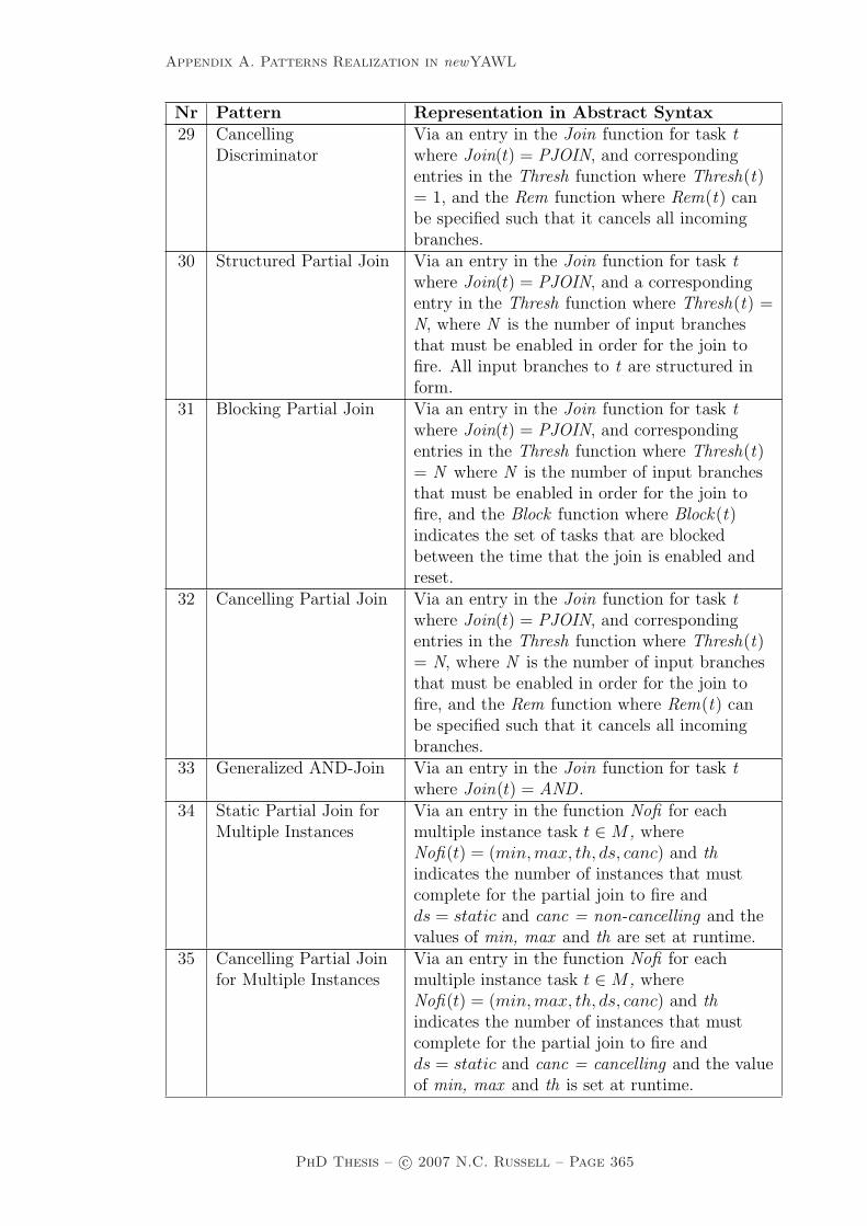
Appendix A. Patterns Realization in newYAWL
Nr Pattern Representation in Abstract Syntax29 Cancelling
DiscriminatorVia an entry in the Join function for task twhere Join(t) = PJOIN, and correspondingentries in the Thresh function where Thresh(t)= 1, and the Rem function where Rem(t) canbe specified such that it cancels all incomingbranches.
30 Structured Partial Join Via an entry in the Join function for task twhere Join(t) = PJOIN, and a correspondingentry in the Thresh function where Thresh(t) =N, where N is the number of input branchesthat must be enabled in order for the join tofire. All input branches to t are structured inform.
31 Blocking Partial Join Via an entry in the Join function for task twhere Join(t) = PJOIN, and correspondingentries in the Thresh function where Thresh(t)= N where N is the number of input branchesthat must be enabled in order for the join tofire, and the Block function where Block(t)indicates the set of tasks that are blockedbetween the time that the join is enabled andreset.
32 Cancelling Partial Join Via an entry in the Join function for task twhere Join(t) = PJOIN, and correspondingentries in the Thresh function where Thresh(t)= N, where N is the number of input branchesthat must be enabled in order for the join tofire, and the Rem function where Rem(t) canbe specified such that it cancels all incomingbranches.
33 Generalized AND-Join Via an entry in the Join function for task twhere Join(t) = AND .
34 Static Partial Join forMultiple Instances
Via an entry in the function Nofi for eachmultiple instance task t ∈ M , whereNofi(t) = (min,max, th, ds, canc) and thindicates the number of instances that mustcomplete for the partial join to fire andds = static and canc = non-cancelling and thevalues of min, max and th are set at runtime.
35 Cancelling Partial Joinfor Multiple Instances
Via an entry in the function Nofi for eachmultiple instance task t ∈ M , whereNofi(t) = (min,max, th, ds, canc) and thindicates the number of instances that mustcomplete for the partial join to fire andds = static and canc = cancelling and the valueof min, max and th is set at runtime.
PhD Thesis – c© 2007 N.C. Russell – Page 365

Appendix A. Patterns Realization in newYAWL
Nr Pattern Representation in Abstract Syntax36 Dynamic Partial Join
for Multiple InstancesVia an entry in the function Nofi for eachmultiple instance task t ∈ M , whereNofi(t) = (min,max, th, ds, canc) and thindicates the number of instances that mustcomplete for the partial join to fire andds = dynamic.
37 Acyclic SynchronizingMerge
Via an entry in the Join function for task twhere Join(t) = OR such that none of the inputbranches to t are part of a cycle.
38 General SynchronizingMerge
Via an entry in the Join function for task twhere Join(t) = OR.
39 Critical Section By encoding a structure of the form indicatedin Fig 2.57 in the flow relation F which includesall of the tasks to be serialized.
40 Interleaved Routing By encoding a structure of the form indicatedin Fig 2.58 in the flow relation F which includesall of the tasks to be interleaved.
41 Thread Merge Via an entry in the Join function for task twhere Join(t) = THREAD and a correspondingentry in the ThreadIn function whereThreadIn(t) = N where N is the number ofexecution threads to be merged.
42 Thread Split Via an entry in the Split function for task twhere Split(t) = THREAD and a correspondingentry in the ThreadOut function whereThreadOut(t) = N where N is the number ofexecution threads to be created.
43 Explicit Termination No direct representation. A newYAWL processinstance is assumed to be complete when thethread of control reaches the output condition oof a top-level newYAWL-net.
PhD Thesis – c© 2007 N.C. Russell – Page 366

Appendix A. Patterns Realization in newYAWL
A.2 Data patterns
Nr Pattern Representation in Abstract Syntax
1 Task Data Via a variable v ∈ VarID with an entry in theVarType function where VarType(v) = Taskand a corresponding entry in VTmap such thatVTmap(v) identifies the task to which thevariable maps.
2 Block Data Via a variable v ∈ VarID with an entry in theVarType function where VarType(v) = Blockand a corresponding entry in VBmap such thatVBmap(v) identifies the newYAWL-net towhich the variable maps.
3 Scope Data Via a variable v ∈ VarID with an entry in theVarType function where VarType(v) = Scopeand a corresponding entry in VSmap such thatVSmap(v) identifies the scope to which thevariable maps.
4 Multiple Instance Data Via a variable v ∈ VarID with an entry in theVarType function where VarType(v) = MI anda corresponding entry in VMmap such thatVMmap(v) identifies the multiple-instance taskto which the variable maps.
5 Case Data Via a variable v ∈ VarID with an entry in theVarType function where VarType(v) = Caseand v ∈ VCmap.
6 Folder Data Via a variable v ∈ VarID with an entry in theVarType function where VarType(v) = Folderand a corresponding entry in VFmap such thatVFmap(v) identifies the folder to which thevariable maps.
7 Global Data Via a variable v ∈ VarID with an entry in theVarType function where VarType(v) = Globaland v ∈ VGmap.
8 Environment Data Environment variables are defined in theoperating environment and hence are externalto the newYAWL abstract syntax. They areaccessed via push and pull operations in thenewYAWL semantic model that interchangetheir values with internal newYAWL dataelements.
9 Task to Task Via an entry in the InPar function wheretF , tT ∈ TA identify the tasks the data elementis being passed from and to, and vF , vT ∈ VarIDidentify the task variables the value is beingpassed between such that InPar(tT , vT ) maps toan expression which identifies tF and vF .
PhD Thesis – c© 2007 N.C. Russell – Page 367

Appendix A. Patterns Realization in newYAWL
Nr Pattern Representation in Abstract Syntax10 Block Task to
SubprocessDecomposition
Via an entry in the InNet function wheretB ∈ TC identifies the block task the dataelement is being passed to, and vF , vT ∈ VarIDidentify the variables the value is being passedbetween such that InNet(tB, vT ) maps to anexpression which identifies vF .
11 SubprocessDecomposition to BlockTask
Via an entry in the OutNet function wheretB ∈ TC identifies the block task the dataelement is being passed from, andvF , vT ∈ VarID identify the variables the valueis being passed between such thatOutNet(tB, vT ) maps to an expression whichidentifies vF .
12 To Multiple InstanceTask
Via an entry in the MIInPar function wheretM ∈ M identifies the multiple instance task thedata element is being passed to, andvT ∈ P(VarID) identifies the multiple instancevariables the data is being passed to, andvF ∈ VarID identifies the variable the value isbeing sourced from, such that MIInPar(tM , vT )maps to an expression which identifies vF . Notethat vF is tabular in form and the columnnames correspond to the set of variable namesvT occuring in each instance of the multipleinstance task.
13 From Multiple InstanceTask
Via an entry in the MIOutPar function wheretM ∈ M identifies the multiple instance task thedata element(s) is being passed from, andvT ∈ VarID identifies the variable the data isbeing passed to, and vF ∈ P(VarID) identifiesthe variables the value is being sourced from,such that MIOutPar(tM , vT ) maps to anexpression which identifies vF . Note that vT istabular in form and the column namescorrespond to the set of variable names vF
occuring in each instance of the multipleinstance task.
14 Case to Case Via the use of folder variables, identified by thefunction VFmap, which are variables that arecommon to a number of process instances. Eachprocess instance is passed a list of folders(containing variables) that it can access atinitiation.
PhD Thesis – c© 2007 N.C. Russell – Page 368

Appendix A. Patterns Realization in newYAWL
Nr Pattern Representation in Abstract Syntax15 Task to Environment -
Push-OrientedNot explicitly identified in the newYAWLabstract syntax although directly supported innewYAWL. Data interchange between taskvariables and environment variables is initiatedvia the process push operation in thenewYAWL semantic model.
16 Environment to Task -Pull-Oriented
Not explicitly identified in the newYAWLabstract syntax although directly supported innewYAWL. Data interchange between taskvariables and environment variables is initiatedvia the process pull operation in the newYAWLsemantic model.
17 Environment to Task -Push-Oriented
Not explicitly identified in the newYAWLabstract syntax although directly supported innewYAWL. Data interchange between taskvariables and environment variables is initiatedvia the environment push operation in thenewYAWL semantic model.
18 Task to Environment -Pull-Oriented
Not explicitly identified in the newYAWLabstract syntax although directly supported innewYAWL. Data interchange between taskvariables and environment variables is initiatedvia the environment pull operation in thenewYAWL semantic model.
19 Case to Environment -Push-Oriented
Not explicitly identified in the newYAWLabstract syntax although directly supported innewYAWL. Data interchange between casevariables and environment variables is initiatedvia the process push operation in thenewYAWL semantic model.
20 Environment to Case -Pull-Oriented
Not explicitly identified in the newYAWLabstract syntax although directly supported innewYAWL. Data interchange between casevariables and environment variables is initiatedvia the process pull operation in the newYAWLsemantic model.
21 Environment to Case -Push-Oriented
Not explicitly identified in the newYAWLabstract syntax although directly supported innewYAWL. Data interchange between casevariables and environment variables is initiatedvia the environment push operation in thenewYAWL semantic model.
PhD Thesis – c© 2007 N.C. Russell – Page 369

Appendix A. Patterns Realization in newYAWL
Nr Pattern Representation in Abstract Syntax22 Case to Environment -
Pull-OrientedNot explicitly identified in the newYAWLabstract syntax although directly supported innewYAWL. Data interchange between casevariables and environment variables is initiatedvia the environment pull operation in thenewYAWL semantic model.
23 Global to Environment- Push-Oriented
Not explicitly identified in the newYAWLabstract syntax although directly supported innewYAWL. Data interchange between globalvariables and environment variables is initiatedvia the process push operation in thenewYAWL semantic model.
24 Environment to Global- Pull-Oriented
Not explicitly identified in the newYAWLabstract syntax although directly supported innewYAWL. Data interchange between globalvariables and environment variables is initiatedvia the process pull operation in the newYAWLsemantic model.
25 Environment to Global- Push-Oriented
Not explicitly identified in the newYAWLabstract syntax although directly supported innewYAWL. Data interchange between globalvariables and environment variables is initiatedvia the environment push operation in thenewYAWL semantic model.
26 Global to Environment- Pull-Oriented
Not explicitly identified in the newYAWLabstract syntax although directly supported innewYAWL. Data interchange between globalvariables and environment variables is initiatedvia the environment pull operation in thenewYAWL semantic model.
27 Data Transfer by Value- Incoming
All data passing in newYAWL is based on theuse of data-based parameters and hence all datapassing is by value.
28 Data Transfer by Value- Outgoing
All data passing in newYAWL is based on theuse of data-based parameters and hence all datapassing is by value.
PhD Thesis – c© 2007 N.C. Russell – Page 370

Appendix A. Patterns Realization in newYAWL
Nr Pattern Representation in Abstract Syntax29 Data Transfer - Copy
In/Copy OutVia an entries in the InPar and OutParfunctions where t ∈ TA identifies the task thedata element is being passed to and from, andvT , vS ∈ VarID identify the task and sourcevariables that the data element is copied into attask commencement and back to at taskcompletion respectively. InPar(t, vT ) maps toan expression which identifies tS andOutPar(t, vS) maps to an expression whichidentifies vT . There is also an entry in the Lockfunction such that vS ∈ Lock(t) ensuring thatthe source variable is locked whilst the dataelement is being used by task t (and resides invT ).
30 Data Transfer byReference - Unlocked
Not supported in newYAWL.
31 Data Transfer byReference - With Lock
Not directly supported in newYAWL howeverthere is the ability to specify task locks onvariables via the Lock function, where for t ∈ T,Lock(t) identifies those variables that t musthold locks on before it can proceed withexecution.
32 Data Transformation -Input
All data passing in newYAWL is based on theuse of function-based parameters. Each inputparameter p ∈ InPar has associated with it afunction which, when evaluated, determines thevalue of the input parameter. The function canbe arbitrarily complex in form and cantransform any input variables passed to it.
33 Data Transformation -Output
All data passing in newYAWL is based on theuse of function-based parameters. Each outputparameter p ∈ OutPar has associated with it afunction which, when evaluated, determines thevalue of the output parameter. The functioncan be arbitrarily complex in form and cantransform any input variables passed to it.
34 Task Precondition -Data Existence
Via an entry in the Pre function for task t ∈ T ,where Pre(t) identifies a Boolean function thatdetermines if t can commence based on a set ofinput parameters that are passed to it. Weassume that the language for specifyingfunctions includes the ability to evaluate theexistence of data elements.
PhD Thesis – c© 2007 N.C. Russell – Page 371

Appendix A. Patterns Realization in newYAWL
Nr Pattern Representation in Abstract Syntax35 Task Precondition -
Data ValueVia an entry in the Pre function for task t ∈ T ,where Pre(t) identifies a Boolean function thatdetermines if t can commence based on a set ofinput parameters that are passed to it. Weassume that the language for specifyingfunctions includes the ability to test the valueof data elements.
36 Task Postcondition -Data Existence
Via an entry in the Post function for taskt ∈ T , where Post(t) identifies a Booleanfunction that determines if t can completebased on a set of input parameters that arepassed to it. We assume that the language forspecifying functions includes the ability toevaluate the existence of data elements.
37 Task Postconditon -Data Value
Via an entry in the Post function for taskt ∈ T , where Post(t) identifies a Booleanfunction that determines if t can completebased on a set of input parameters that arepassed to it. We assume that the language forspecifying functions includes the ability to testthe value of data elements.
38 Event-Based TaskTrigger
Via an entry in the Trig function for thetriggered task such that Trig(t) indicates the idof the trigger associated with t. When a triggeris raised for task t, any data elements to bepassed are simultaneously pushed intoassociated task variables.
39 Data-Based TaskTrigger
Via an entry in the Pre function for task t ∈ T ,where Pre(t) identifies a Boolean function thatdetermines if t can commence based on a set ofinput parameters that are passed to it. Theprocess definition containing t is structuredsuch that t is enabled as soon as the processinstance is initiated, however it cannotcommence until the data-based precondition issatisfied.
40 Data-Based Routing Via an entry in the Split function for the task twith which the pattern is associated whereSplit(t) ∈ {OR,XOR}. For an XOR-split, theevaluation sequence for each outgoing arc from tis indicated by <t
XOR. Entries in the ArcCondfunction define the arc expression for eachoutgoing branch from task t. Finally an entryin the Default function Default(t) denotes thedefault outgoing arc that is taken if no arccondition evaluates positively for task t.
PhD Thesis – c© 2007 N.C. Russell – Page 372
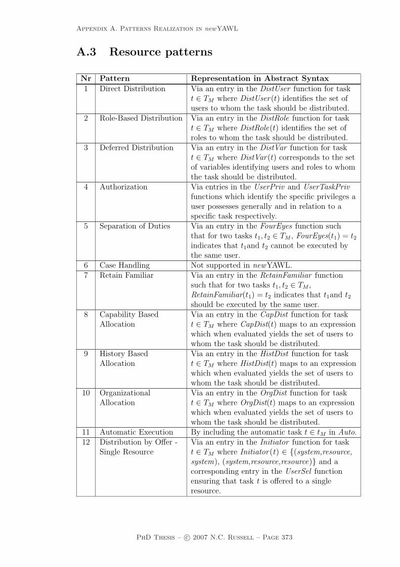
Appendix A. Patterns Realization in newYAWL
A.3 Resource patterns
Nr Pattern Representation in Abstract Syntax
1 Direct Distribution Via an entry in the DistUser function for taskt ∈ TM where DistUser(t) identifies the set ofusers to whom the task should be distributed.
2 Role-Based Distribution Via an entry in the DistRole function for taskt ∈ TM where DistRole(t) identifies the set ofroles to whom the task should be distributed.
3 Deferred Distribution Via an entry in the DistVar function for taskt ∈ TM where DistVar(t) corresponds to the setof variables identifying users and roles to whomthe task should be distributed.
4 Authorization Via entries in the UserPriv and UserTaskPrivfunctions which identify the specific privileges auser possesses generally and in relation to aspecific task respectively.
5 Separation of Duties Via an entry in the FourEyes function suchthat for two tasks t1, t2 ∈ TM , FourEyes(t1) = t2indicates that t1and t2 cannot be executed bythe same user.
6 Case Handling Not supported in newYAWL.7 Retain Familiar Via an entry in the RetainFamiliar function
such that for two tasks t1, t2 ∈ TM ,RetainFamiliar(t1) = t2 indicates that t1and t2should be executed by the same user.
8 Capability BasedAllocation
Via an entry in the CapDist function for taskt ∈ TM where CapDist(t) maps to an expressionwhich when evaluated yields the set of users towhom the task should be distributed.
9 History BasedAllocation
Via an entry in the HistDist function for taskt ∈ TM where HistDist(t) maps to an expressionwhich when evaluated yields the set of users towhom the task should be distributed.
10 OrganizationalAllocation
Via an entry in the OrgDist function for taskt ∈ TM where OrgDist(t) maps to an expressionwhich when evaluated yields the set of users towhom the task should be distributed.
11 Automatic Execution By including the automatic task t ∈ tM in Auto.12 Distribution by Offer -
Single ResourceVia an entry in the Initiator function for taskt ∈ TM where Initiator(t) ∈ {(system,resource,system), (system,resource,resource)} and acorresponding entry in the UserSel functionensuring that task t is offered to a singleresource.
PhD Thesis – c© 2007 N.C. Russell – Page 373

Appendix A. Patterns Realization in newYAWL
Nr Pattern Representation in Abstract Syntax13 Distribution by Offer -
Multiple ResourcesVia an entry in the Initiator function for taskt ∈ TM where Initiator(t) ∈ {(system,resource,system), (system,resource,resource)}.
14 Distribution byAllocation - SingleResource
Via an entry in the Initiator function for taskt ∈ TM where Initiator(t) ∈ {(system,system,system),(system,system,resource)} and acorresponding entry in the UserSel functionensuring that task t is allocated to a singleresource.
15 Random Allocation Via an entry in the UserSel function for taskt ∈ TM such that UserSel(t) = random.
16 Round RobinAllocation
Via an entry in the UserSel function for taskt ∈ TM such that UserSel(t) = round-robin.
17 Shortest Queue Via an entry in the UserSel function for taskt ∈ TM such that UserSel(t) = shortest-queue.
18 Early Distribution Not supported in newYAWL.19 Distribution on
EnablementIn newYAWL all tasks are distributed as soonas they are enabled.
20 Late Distribution By ensuring that no user u ∈ UserID possessesthe concurrent and choose privileges (asrecorded in the function UserTaskPriv) for anytask t ∈ TM in the process, and that all tasksmust be immediately started when distributedas indicated via an entry in the Initiatorfunction where Initiator(t) ∈ {(system,system,system)}. This ensures that tasks can only bedistributed when there is a resource availablewho can immediately start them.
21 Resource-InitiatedAllocation
Via an entry in the Initiator function for taskt ∈ TM where Initiator(t) ∈ {(system,resource,resource),(resource,resource,resource)} andcorresponding entries in the UserPriv functionfor each user u ∈ UserID to whom the taskmight be distributed such thatchoose ∈ UserPriv(u).
22 Resource-InitiatedExecution - AllocatedWork Item
Via an entry in the Initiator function for taskt ∈ TM where Initiator(t) ∈ {(system,system,resource),(system,resource,resource),(resource,system,resource),(resource,resource,resource)}and corresponding entries in the UserPrivfunction for each user u ∈ UserID to whom thetask might be distributed such thatchoose ∈ UserPriv(u) and the UserTaskPrivfunction such that start ∈ UserTaskPriv(u, t).
PhD Thesis – c© 2007 N.C. Russell – Page 374

Appendix A. Patterns Realization in newYAWL
Nr Pattern Representation in Abstract Syntax23 Resource-Initiated
Execution - OfferedWork Item
Via an entry in the Initiator function for taskt ∈ TM where Initiator(t) ∈ {(system,resource,system),(resource,resource,system)} andcorresponding entries in the UserPriv functionfor each user u ∈ UserID to whom the taskmight be distributed such thatchoose ∈ UserPriv(u) and the UserTaskPrivfunction such that start ∈ UserTaskPriv(u, t).
24 System DeterminedWork Queue Content
By default in newYAWL the system imposes anordering strategy on user worklists that ensuresthe oldest work item is displayed first (i.e. it isat the head of the workqueue).
25 Resource-DeterminedWork Queue Content
Via an entry in the UserPriv function for a useru ∈ UserID such that reorder ∈ UserPriv(u).
26 Selection Autonomy Via an entry in the UserPriv function for a useru ∈ UserID such that choose ∈ UserPriv(u).
27 Delegation Via an entry in the UserPriv function for taskt ∈ TM and user u ∈ UserID such thatdelegate ∈ UserTaskPriv(u, t).
28 Escalation Not explicitly identified in the newYAWLabstract syntax although directly supported innewYAWL via the operations in themanagement-intervention transition. Theprocess administrator can intervene at anypoint during the offer, allocation or execution ofa work item and reroute it to one or more otherusers.
29 Deallocation Via an entry in the UserTaskPriv function fortask t ∈ TM and user u ∈ UserID such thatdeallocate ∈ UserTaskPriv(u, t).
30 Stateful Reallocation Via an entry in the UserTaskPriv function fortask t ∈ TM and user u ∈ UserID such thatreallocate state ∈ UserTaskPriv(u, t).
31 Stateless Reallocation Via an entry in the UserTaskPriv function fortask t ∈ TM and user u ∈ UserID such thatreallocate ∈ UserTaskPriv(u,t).
32 Suspension/Resumption Via an entry in the UserTaskPriv function fortask t ∈ TM and user u ∈ UserID such thatsuspend ∈ UserTaskPriv(u, t).
33 Skip Via an entry in the UserTaskPriv function fortask t ∈ TM and user u ∈ UserID such thatskip ∈ UserTaskPriv(u, t).
34 Redo Not supported in newYAWL.35 Pre-Do Not supported in newYAWL.36 Commencement on
CreationVia an entry in the Initiator function for taskt ∈ TM where Initiator(t) ∈ {(system,system,system)}.
PhD Thesis – c© 2007 N.C. Russell – Page 375

Appendix A. Patterns Realization in newYAWL
Nr Pattern Representation in Abstract Syntax37 Commencement on
AllocationVia an entry in the Initiator function for taskt ∈ TM where Initiator(t) ∈ {(system,resource,system), (resource,resource,system)}.
38 Piled Execution Via an entry in the UserTaskPriv function fortask t ∈ TM and user u ∈ UserID such thatpiledexec ∈ UserTaskPriv(u, t).
39 Chained Execution Via an entry in the UserPriv function for useru ∈ UserID such that chainedexec ∈UserPriv(u).
40 ConfigurableUnallocated Work ItemVisibility
Via an entry in the UserPriv function for useru ∈ UserID such that viewoffers ∈ UserPriv(u).
41 Configurable AllocatedWork Item Visibility
Via an entry in the UserPriv function for useru ∈ UserID such that viewallocs ∈ UserPriv(u).
42 Simultaneous Execution Via an entry in the UserPriv function for useru ∈ UserID such that concurrent ∈ UserPriv(u).
43 Additional Resources Not supported in newYAWL.
PhD Thesis – c© 2007 N.C. Russell – Page 376
Appendix B. Mathematical Notations
Appendix B
Mathematical Notations
This appendix outlines mathematical notations used in this thesis that are notin general use and hence merit some further explanation.
In the context of a newYAWL net, where t ∈ T is a task, •t denotes the inputconditions or tasks (as in newYAWL, tasks can be directly linked to tasks) tothe task and t• denotes the output conditions or tasks. In a more formal sense,•t = {x ∈ T ∪ C | (x, t) ∈ F} where T is the set of tasks, C the set of conditionsand F the flow relation (i.e. the set of arcs) associated with a net. Similarly,t• = {x ∈ T ∪ C | (t, x) ∈ F}.
In the context of a function f : A → B, range restriction of f over a set R ⊆ Bis defined by f B R = {(a, b) ∈ f | b ∈ R}.
P(X) denotes the power set of X where Y ∈ P(X) ⇔ Y ⊆ X.
P+(X) denotes the power set of X without the empty set ie. P+(X) = P(X)\{∅}.
Let V = {v1, ...vn} be a (non-empty) set and < a strict total order over V ,then [V ]< denotes the sequence [v1, ...vn] such that ∀1≤i≤j<n[vi < vj] and everyelement of V occurs precisely once in the sequence. [v] denotes the sequence inarbitrary order. Sequence comprehension is defined as [E(x) | x ← [V ]<] yieldinga sequence [E(v1)...E(vn)].
PhD Thesis – c© 2007 N.C. Russell – Page 377

Bibliography
[AAA+96] G. Alonso, D. Agrawal, A. El Abbadi, M. Kamath, G. Gunthor,and C. Mohan. Advanced transaction models in workflow contexts.In S.Y.W. Su, editor, Proceedings of the 12th International Con-ference on Data Engineering, pages 574–581, New Orleans, USA,1996.
[AADH04] W.M.P. van der Aalst, L. Aldred, M. Dumas, and A.H.M. terHofstede. Design and implementation of the YAWL system. InA. Persson and J. Stirna, editors, Proceedings of the 16th Interna-tional Conference on Advanced Information Systems Engineering(CAiSE 04), pages 142–159, Riga, Latvia, 2004. Springer Verlag.
[Aal96] W.M.P. van der Aalst. Three good reasons for using a Petri-net-based workflow management system. In S. Navathe andT. Wakayama, editors, Proceedings of the International WorkingConference on Information and Process Integration in Enterprises(IPIC96), pages 179–201, Cambridge, MA, USA, 1996.
[Aal98] W.M.P. van der Aalst. The application of Petri nets to work-flow management. Journal of Circuits, Systems and Computers,8(1):21–66, 1998.
[Aal99] W.M.P. van der Aalst. Formalization and verification of event-driven process chains. Information and Software Technology,41(10):639–650, 1999.
[Aal01] W.M.P. van der Aalst. Exterminating the dynamic change bug: Aconcrete approach to support workflow change. Information Sys-tems Frontiers, 3(3):297–317, 2001.
[Aal03] W.M.P. van der Aalst. Dont go with the flow: Web services compo-sition standards exposed. IEEE Intelligent Systems, 18(1):72–76,2003.
[ABHK00] W.M.P. van der Aalst, A.P. Barros, A.H.M. ter Hofstede, andB. Kiepuszewski. Advanced workflow patterns. In O. Et-zion and P. Scheuermann, editors, Proceedings of the Fifth IF-CIS International Conference on Cooperative Information Systems(CoopIS’2000), volume 1901 of Lecture Notes in Computer Science,pages 18–29, Eilat, Israel, 2000. Springer.
378

[ABV+99] W. M. P. van der Aalst, T. Basten, H.M.W. Verbeek, P.A.C. Verk-oulen, and M. Voorhoeve. Adaptive workflow – on the interplaybetween flexibility and support. In J. Filipe and J. Cordeiro, edi-tors, Proceedings of the 1st International Conference on EnterpriseInformation Systems, pages 353–360, Setubal, Portugal, 1999.
[ACD+03] T. Andrews, F. Curbera, H. Dholakia, Y. Goland, J. Klein,F. Leymann, K. Liu, D. Roller, D. Smith, S. Thatte, I. Trick-ovic, and S. Weerawarana. Business Process Execution Languagefor Web Services version 1.1. Technical report, 2003. http:
//xml.coverpages.org/BPELv11-May052003Final.pdf.
[Ada07] M.J. Adams. Facilitating Dynamic Flexibility and Exception Han-dling for Workflows. PhD thesis, Queensland University of Tech-nology, 2007.
[ADH+05] W.M.P. van der Aalst, M. Dumas, A.H.M. ter Hofstede, N. Russell,H.M.W. Verbeek, and P. Wohed. Life after BPEL? In M. Bravetti,L. Kloul, and G. Zavattaro, editors, Proceedings of the Interna-tional Workshop on Web Services and Formal Methods (WS-FM2005), volume 3670 of Lecture Notes in Computer Science, pages35–50, Versailles, France, 2005. Springer.
[ADK02] W.M.P. van der Aalst, J. Desel, and E. Kindler. On the semanticsof EPCs: A vicious circle. In M. Rump and F.J. Nuttgens, edi-tors, Proceedings of the EPK 2002: Business Process Managementusing EPCs, pages 71–80, Trier, Germany, 2002. Gesellschaft furInformatik.
[AH02] W.M.P van der Aalst and K.M. van Hee. Workflow Management:Models, Methods and Systems. MIT Press, Cambridge, MA, USA,2002.
[AH05] W.M.P. van der Aalst and A.H.M. ter Hofstede. YAWL: Yetanother workflow language. Information Systems, 30(4):245–275,2005.
[AHD05] W.M.P van der Aalst, A.H.M ter Hofstede, and M. Dumas. Pat-terns of process modeling. In M. Dumas, W.M.P van der Aalst,and A.H.M ter Hofstede, editors, Process-Aware Information Sys-tems: Bridging People and Software through Process Technology,pages 179–203. Wiley-Interscience, Hoboken, NJ, USA, 2005.
[AHEA05] M. Adams, A.H.M. ter Hofstede, D. Edmond, and W.M.P. van derAalst. Facilitating flexibility and dynamic exception handling inworkflows through worklets. In O. Belo, J. Eder, O. Pastor, andJ. Falcao e Cunha, editors, Proceedings of the CAiSE’05 Forum,volume 161 of CEUR Workshop Proceedings, pages 45–50, Porto,Portugal, 2005. FEUP.
PhD Thesis – c© 2007 N.C. Russell – Page 379

[AHEA07] M. Adams, A.H.M. ter Hofstede, D. Edmond, and W.M.P van derAalst. Dynamic and extensible exception handling for workflow:A service-oriented implementation. Technical Report BPM-07-03,2007. http://www.BPMcenter.org.
[AHKB03] W.M.P. van der Aalst, A.H.M. ter Hofstede, B. Kiepuszewski,and A.P. Barros. Workflow patterns. Distributed and ParallelDatabases, 14(3):5–51, 2003.
[AHW03] W.M.P. van der Aalst, A.H.M. ter Hofstede, and M. Weske. Busi-ness process management: A survey. In W.M.P. van der Aalst,A.H.M. ter Hofstede, and M. Weske, editors, Proceedings of theBusiness Process Management 2003, volume 2678 of Lecture Notesin Computer Science, pages 1–12, Eindhoven, The Netherlands,2003. Springer-Verlag.
[AIS77] C. Alexander, S. Ishikawa, and M. Silverstein. A Pattern Language:Towns, Buildings, Construction. Oxford University Press, NewYork, NY, 1977.
[AK01] W.M.P. van der Aalst and A. Kumar. Team-enabled workflow man-agement systems. Data and Knowledge Engineering, 38(3):335–363, 2001.
[AKV03] W.M.P. van der Aalst, A. Kumar, and H.M.W. Verbeek. Orga-nizational modeling in UML and XML in the context of workflowsystems. In H. Haddad and G. Papadopoulos, editors, Proceedingsof the 18th Annual ACM Symposium on Applied Computing (SAC2003), pages 603–608, Melbourne, Florida, USA, 2003. ACM Press.
[AMP94] A. Agostini, G. De Michelis, and K. Petruni. Keeping workflowmodels as simple as possible. In Proceedings of the Workshopon Computer-Supported Cooperative Work, Petri Nets and RelatedFormalisms within the 15th International Conference on Applica-tion and Theory of Petri Nets, pages 11–29, Zaragoza, Spain, 1994.
[AWG05] W.M.P. van der Aalst, M. Weske, and D. Grunbauer. Case han-dling: A new paradigm for business process support. Data andKnowledge Engineering, 53(2):129–162, 2005.
[BCCT05] M. Brambilla, S. Ceri, S. Comai, and C. Tziviskou. Exceptionhandling in workflow-driven web applications. In A. Ellis andT. Hagino, editors, Proceedings of the 14th International Confer-ence on World Wide Web (WWW 2005), pages 170–179, Chiba,Japan, 2005. ACM Press.
[BCDS01] A. Bonifati, F. Casati, U. Dayal, and M.C. Shan. Warehousingworkflow data: Challenges and opportunities. In P.M.G. Apers,P. Atzeni, S. Ceri, S. Paraboschi, K. Ramamohanarao, and R.T.Snodgrass, editors, Proceedings of the 27th International Confer-ence on Very Large Data Bases (VLDB 2001), pages 649–652,Roma, Italy, 2001. Morgan Kaufmann.
PhD Thesis – c© 2007 N.C. Russell – Page 380

[BJ95] C. Bussler and S. Jablonski. Policy resolution for workflow man-agement systems. In Proceedings of the 28th Hawaii InternationalConference on System Sciences, volume 4, pages 831–840, Wailea,HI, USA, 1995. IEEE Computer Society.
[BK07] F. van Breugel and M. Koshkina. Models and verification of BPEL.Technical report, York University, Toronto, Canada, 2007. http://www.cse.yorku.ca/~franck/research/drafts/tutorial.pdf.
[BM99] A. Borgida and T. Murata. Tolerating exceptions in workflows: Aunified framework for data and processes. In D. Georgakopoulos,W. Prinz, and A.L. Wolf, editors, Proceedings of the InternationalJoint Conference on Work Activities Coordination and Collabora-tion (WACC’99), pages 59–68, San Francisco, USA, 1999.
[BMR+96] F. Buschmann, R. Meunier, H. Rohnert, P. Sommerlad, andM. Stal. Pattern-Oriented Software Architecture: A System of Pat-terns Volume 1. Wiley, Chichester, UK, 1996.
[Bor85] A. Borgida. Language features for flexible handling of exceptionsin information systems. ACM Transactions on Database Systems,10(4):565–603, 1985.
[BPM02] BPMI.org. Business process modeling language 1.0. Technical re-port, 2002. http://www.bpmi.org/specifications.esp.
[BPS01] J.A. Bubenko, A. Persson, and J. Stirna. EKD user guide. Tech-nical report, Royal Institute of Technology (KTH) and StockholmUniversity, Stockholm, Sweden, 2001.
[BRM00] P.A. Buhr and W.Y. Russell Mok. Advanced exception handlingmechanisms. IEEE Trans. Softw. Eng., 26(9):820–836, 2000.
[CCPP99] F. Casati, S. Ceri, S. Paraboschi, and G. Pozzi. Specification andimplementation of exceptions in workflow management systems.ACM Transactions on Database Systems, 24(3):405–451, 1999.
[Che76] P.P. Chen. The entity-relationship model - toward a unified viewof data. ACM Transactions on Database Systems, 1(1):9–36, 1976.
[CKO92] B. Curtis, M.J. Kellner, and J. Over. Process modelling. Commu-nications of the ACM, 35(9):75–90, 1992.
[CL84] W.B. Croft and L. Lefkowitz. Task support in an office system.ACM Transactions on Office Information Systems, 2(3):197–212,1984.
[CLK01] D.K.W. Chiu, Q. Li, and K. Karlapalem. ADOME-WFMS: To-wards cooperative handling of workflow exceptions. In Advancesin Exception Handling Techniques, pages 271–288. Springer-Verlag,New York, NY, USA, 2001.
PhD Thesis – c© 2007 N.C. Russell – Page 381
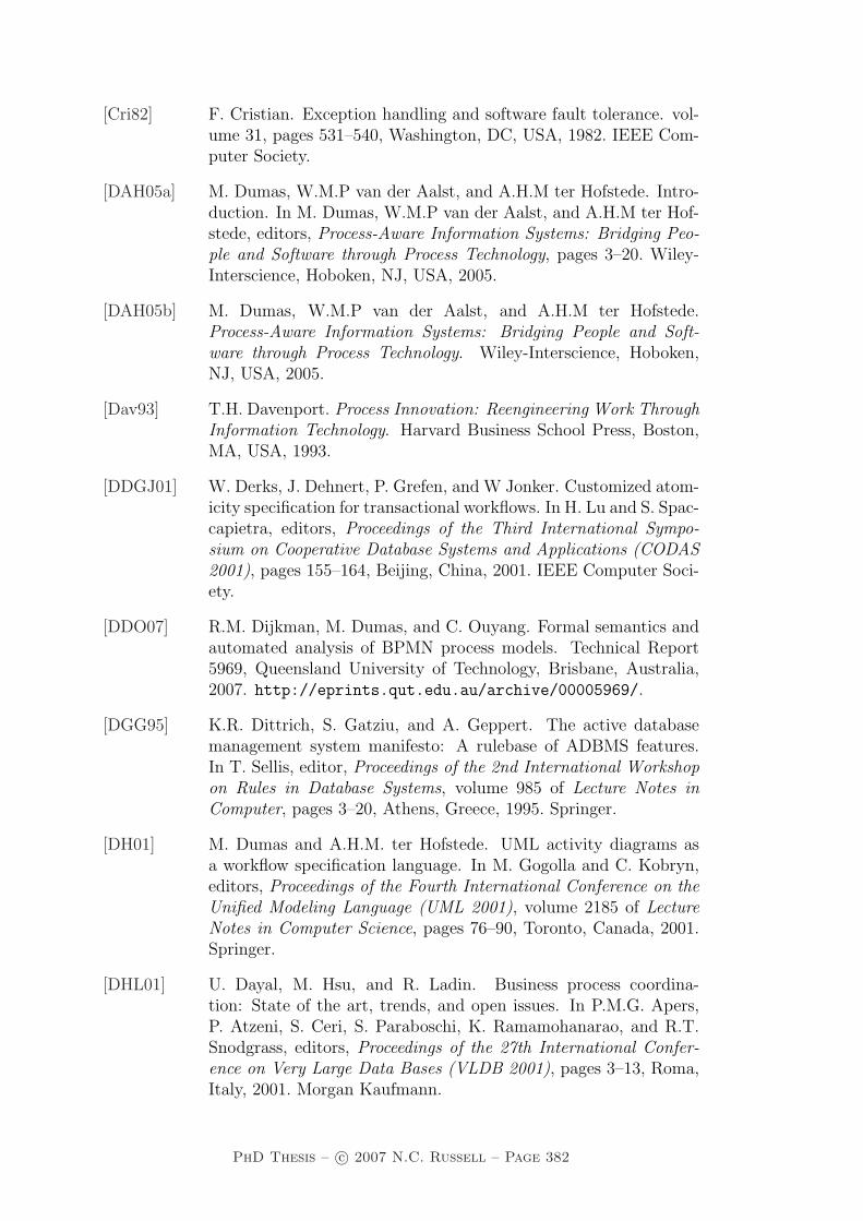
[Cri82] F. Cristian. Exception handling and software fault tolerance. vol-ume 31, pages 531–540, Washington, DC, USA, 1982. IEEE Com-puter Society.
[DAH05a] M. Dumas, W.M.P van der Aalst, and A.H.M ter Hofstede. Intro-duction. In M. Dumas, W.M.P van der Aalst, and A.H.M ter Hof-stede, editors, Process-Aware Information Systems: Bridging Peo-ple and Software through Process Technology, pages 3–20. Wiley-Interscience, Hoboken, NJ, USA, 2005.
[DAH05b] M. Dumas, W.M.P van der Aalst, and A.H.M ter Hofstede.Process-Aware Information Systems: Bridging People and Soft-ware through Process Technology. Wiley-Interscience, Hoboken,NJ, USA, 2005.
[Dav93] T.H. Davenport. Process Innovation: Reengineering Work ThroughInformation Technology. Harvard Business School Press, Boston,MA, USA, 1993.
[DDGJ01] W. Derks, J. Dehnert, P. Grefen, and W Jonker. Customized atom-icity specification for transactional workflows. In H. Lu and S. Spac-capietra, editors, Proceedings of the Third International Sympo-sium on Cooperative Database Systems and Applications (CODAS2001), pages 155–164, Beijing, China, 2001. IEEE Computer Soci-ety.
[DDO07] R.M. Dijkman, M. Dumas, and C. Ouyang. Formal semantics andautomated analysis of BPMN process models. Technical Report5969, Queensland University of Technology, Brisbane, Australia,2007. http://eprints.qut.edu.au/archive/00005969/.
[DGG95] K.R. Dittrich, S. Gatziu, and A. Geppert. The active databasemanagement system manifesto: A rulebase of ADBMS features.In T. Sellis, editor, Proceedings of the 2nd International Workshopon Rules in Database Systems, volume 985 of Lecture Notes inComputer, pages 3–20, Athens, Greece, 1995. Springer.
[DH01] M. Dumas and A.H.M. ter Hofstede. UML activity diagrams asa workflow specification language. In M. Gogolla and C. Kobryn,editors, Proceedings of the Fourth International Conference on theUnified Modeling Language (UML 2001), volume 2185 of LectureNotes in Computer Science, pages 76–90, Toronto, Canada, 2001.Springer.
[DHL01] U. Dayal, M. Hsu, and R. Ladin. Business process coordina-tion: State of the art, trends, and open issues. In P.M.G. Apers,P. Atzeni, S. Ceri, S. Paraboschi, K. Ramamohanarao, and R.T.Snodgrass, editors, Proceedings of the 27th International Confer-ence on Very Large Data Bases (VLDB 2001), pages 3–13, Roma,Italy, 2001. Morgan Kaufmann.
PhD Thesis – c© 2007 N.C. Russell – Page 382

[DS99] W. Du and M.C. Shan. Enterprise workflow resource management.In Proceedings of the Ninth International Workshop on Research Is-sues on Data Engineering: Information Technology for Virtual En-terprises (RIDE-VE’99), pages 108–115, Sydney, Australia, 1999.IEEE Computer Society Press.
[EL95] J. Eder and W. Liebhart. The workflow activity model (WAMO).In S. Laufmann, S. Spaccapietra, and T. Yokoi, editors, Proceedingsof the Third International Conference on Cooperative InformationSystems (CoopIS-95), pages 87–98, Vienna, Austria, 1995. Univer-sity of Toronto Press.
[EL96] J. Eder and W. Liebhart. Workflow recovery. In Proceedings ofthe First IFCIS International Conference on Cooperative Informa-tion Systems (CoopIS’96), pages 124–134, Brussels, Belgium, 1996.IEEE Computer Society.
[EL05] J. Eder and M. Lehmann. Synchronizing copies of external datain workflow management systems. In O. Pastor and J. Falcao eCunha, editors, Proceedings of the 17th International Conferenceon Advanced Information Systems Engineering (CAiSE 2005), vol-ume 3520 of Lecture Notes in Computer Science, pages 248–261,Porto, Portugal, 2005. Springer.
[Elm92] A. Elmagarmid. Database Transaction Models for Advanced Appli-cations. Morgan Kaufmann, San Mateo, CA, USA, 1992.
[EN80] C.A. Ellis and G.J. Nutt. Office information systems and computerscience. ACM Computing Surveys, 12(1):27–60, 1980.
[EN93] C.A. Ellis and G.J. Nutt. Modelling and enactment of workflowsystems. In M. Ajmone Marsan, editor, Proceedings of the 14thInternational Conference on Application and Theory of Petri Nets,volume 691 of Lecture Notes in Computer Science, pages 1–16,Chicago, IL, USA, 1993. Springer.
[EN96] C. Ellis and G. Nutt. Workflow: The process spectrum. In Proceed-ings of the NSF Workshop on Workflow and Process Automationin Information Systems, Athens, GA, USA, 1996.
[EOG02] J. Eder, G.E. Olivotto, and W. Gruber. A data warehouse for work-flow logs. In Y. Han, S. Tai, and D. Wikarski, editors, Proceedingsof the First International Conference on Engineering and Deploy-ment of Cooperative Information Systems (EDCIS 2002), volume2480 of Lecture Notes In Computer Science, pages 1–15, Beijing,China, 2002. Springer.
[EP00] H.E. Eriksson and M. Penker. Business Modeling with UML. OMGPress, New York, NY, USA, 2000.
PhD Thesis – c© 2007 N.C. Russell – Page 383

[FBGL97] M.S. Fox, M. Barbuceanu, M. Gruninger, and J. Lin. An organiza-tional ontology for enterprise modelling. In M. Prietula, K. Carley,and L. Gasser, editors, Stimulating Organizations: ComputationalModels of Institutions and Groups, pages 131–152. AAAI/MITPress, Menlo Park, 1997.
[Fil04] FileNet. The FileNet P8 Process Analyzer/Simulator Student Book1 and 2. FileNet, Cosa Mesa, CA, USA, 2004.
[Fow96] M. Fowler. Analysis Patterns : Reusable Object Models. Addison-Wesley, Boston, MA, USA, 1996.
[FSB06] A. Farrell, M. Sergot, and C. Bartolini. Formalising workflow:A CCS-inspired characterisation of the YAWL workflow patterns.Group Decision and Negotiation, 61(3):213–254, 2006.
[FSG+01] D.F. Ferraiolo, R. Sandhu, S. Gavrila, D.R. Kuhn, and R. Chan-dramouli. Proposed NIST standard for role-based access control.ACM Transactions on Information and System Security, 4(3):224–274, 2001.
[GCDS01] D. Grigori, F. Casati, U. Dayal, and M.C. Shan. Improving businessprocess quality through exception understanding, prediction, andprevention. In P. Apers, P. Atzeni, S. Ceri, S. Paraboschi, K. Ra-mamohanarao, and R. Snodgrass, editors, Proceedings of the 27thInternational Conference on Very Large Data Bases (VLDB’01),pages 159–168, Rome, Italy, 2001. Morgan Kaufmann.
[GHJV95] E. Gamma, R. Helm, R. Johnson, and J. Vlissides. Design Pat-terns: Elements of Reusable Object-Oriented Software. Addison-Wesley, Boston, MA, USA, 1995.
[GHS95] D. Georgakopoulos, M.F. Hornick, and A.P. Sheth. An overviewof workflow management: From process modeling to workflowautomation infrastructure. Distributed and Parallel Databases,3(2):119–153, 1995.
[Goo75] J.B. Goodenough. Exception handling: issues and a proposed no-tation. Commun. ACM, 18(12):683–696, 1975.
[GP03] M. Georgeff and J. Pyke. Dynamic process orchestra-tion, 2003. http://tmitwww.tm.tue.nl/bpm2003/download/WP%
20Dynamic%20Process%20Orchestration%20v1.pdf.
[GRRX01] A.F. Garcia, C.M.F. Rubira, A. Romanovsky, and J. Xu. A com-parative study of exception handling mechanisms for building de-pendable object-oriented software. The Journal of Systems andSoftware, 59(2):197–222, 2001.
[GS77] C. Gane and T. Sarson. Structured Systems Analysis: Tools andTechniques. Prentice-Hall, New York, NY, USA, 1977.
PhD Thesis – c© 2007 N.C. Russell – Page 384

[GT83] S. Gibbs and D. Tsichritzis. A data modelling approach for officeinformation systems. ACM Transactions on Office InformationSystems, 1(4):299–319, 1983.
[GV06] P.W.P.J. Grefen and J. Vonk. A taxonomy of transactional work-flow support. International Journal of Cooperative InformationSystems, 15(1):87–118, 2006.
[GVA01] P. Grefen, J. Vonk, and P. Apers. Global transaction support forworkflow management systems: From formal specification to prac-tical implementation. The VLDB Journal, 10(4):316–333, 2001.
[HA98] C. Hagen and G. Alonso. Flexible exception handling inthe OPERA process support system. In Proceedings of the18th International Conference on Distributed Computing Systems(ICDCS’98), pages 526–533, Amsterdam, The Netherlands, 1998.IEEE Computer Society.
[HA00] C. Hagen and G. Alonso. Exception handling in workflow man-agement systems. IEEE Transactions on Software Engineering,26(10):943–958, 2000.
[Hal01] T.A. Halpin. Information Modeling and Relational Databases:From Conceptual Analysis to Logical Design. Morgan KaufmannPublishers, San Francisco, CA, USA, 2001.
[Har87] D. Harel. Statecharts: A visual formalism for complex systems.Science of Computer Programming, 8(3):231–274, 1987.
[Har91] H.J. Harrington. Business Process Improvement: The Break-through Strategy for Total Quality, Productivity and Competitive-ness. McGraw-Hill, New York, NY, USA, 1991.
[Har93] J.V. Harrison. Active rules in deductive databases. In Proceed-ings of the Second International Conference on Information andKnowledge Management, pages 174–183, Washington D.C., USA,1993. ACM Press.
[Hay95] D.C. Hay. Data Model Patterns, Conventions of Thought. DorsetHouse, New York, NY, USA, 1995.
[HC93] M. Hammer and J. Champy. Reengineering the Corporation: AManifesto for Business Revolution. Harper Business, New York,NY, USA, 1993.
[HHKW77] M. Hammer, W.G. Howe, V.J. Kruskal, and I. Wladawsky. A veryhigh level programming language for data processing applications.Communications of the ACM, 20(11):832–840, 1977.
[HN93] A.H.M ter Hofstede and E.R. Nieuwland. Task structure semanticsthrough process algebra. Software Engineering Journal, 8(1):14–20,1993.
PhD Thesis – c© 2007 N.C. Russell – Page 385

[Hol86] A.W. Holt. Coordination technology and Petri nets. In G. Rozen-berg, editor, Advances in Petri Nets 1985, volume 222 of Lec-ture Notes in Computer Science, pages 278–296. Springer, London,1986.
[HS99] Y.N. Huang and M.C. Shan. Policies in a resource managerof workflow systems: Modeling, enforcement and management.Technical Report HPL-98-156, 1999. http://www.hpl.hp.com/
techreports/98/HPL-98-156.pdf.
[HT04] S.Y. Hwang and J. Tang. Consulting past exceptions to facilitateworkflow exception handling. Decision Support Systems, 37(1):49–69, 2004.
[HW04] G. Hohpe and B. Woolf. Enterprise Integration Patterns : De-signing, Building, and Deploying Messaging Solutions. Addison-Wesley, Boston, MA, USA, 2004.
[IBM03a] IBM. IBM Websphere MQ Workflow – Getting Started with Build-time – Version 3.4. IBM Corp., 2003.
[IBM03b] IBM. IBM Websphere MQ Workflow – Programming Guide – Ver-sion 3.4. IBM Corp., 2003.
[IBM06] IBM Corp. WebSphere Integration Developer 6.0.2 Documenta-tion. Armonk, NY, USA, 2006. http://publib.boulder.ibm.
com/infocenter/dmndhelp/v6rxmx/index.jsp.
[JB96] S. Jablonski and C. Bussler. Workflow Management: ModelingConcepts, Architecture and Implementation. Thomson ComputerPress, London, UK, 1996.
[Jen97] K. Jensen. Coloured Petri Nets. Basic Concepts, Analysis Meth-ods and Practical Use. Volume 1, Basic Concepts. Monographs inTheoretical Computer Science. Springer-Verlag, Berlin, Germany,1997.
[KD00] M. Klein and C. Dellarocas. A knowledge-based approach tohandling exceptions in workflow systems. Journal of Computer-Supported Collaborative Work, 9(3-4):399–412, 2000.
[KHA03] B. Kiepuszewski, A.H.M. ter Hofstede, and W.M.P. van der Aalst.Fundamentals of control flow in workflows. Acta Informatica,39(3):143–209, 2003.
[KHB00] B. Kiepuszewski, A.H.M. ter Hofstede, and C. Bussler. On struc-tured workflow modelling. In B. Wangler and L. Bergman, ed-itors, Proceedings of the 12th International Conference on Ad-vanced Information Systems Engineering CAiSE 2000, volume 1789of Lecture Notes in Computer Science, Stockholm, Sweden, 2000.Springer.
PhD Thesis – c© 2007 N.C. Russell – Page 386
[Kie03] B. Kiepuszewski. Expressiveness and Suitability of Languages forControl Flow Modelling in Workflows. PhD thesis, QueenslandUniversity of Technology, Brisbane, Australia, 2003.
[Kin06] E. Kindler. On the semantics of EPCs: Resolving the vicious circle.Data and Knowledge Engineering, 56(1):23–40, 2006.
[KKL+05] M. Kloppman, D. Koenig, F. Leymann, G. Pfau, A. Rickayzen,C. von Riegen, P. Schmidt, and I. Trickovic. WS-BPEL extensionfor people - BPEL4People, 2005. ftp://www6.software.ibm.com/software/developer/library/ws-bpel4people.pdf.
[KKNR06] J. Koehler, J.M. Kuster, J. Novatnack, and K. Ryndina. Aclassification of UML2 activity diagrams. Technical Report RZ3673 (99683), IBM Research GmbH, Zurich Research Laboratory,Zurich, Switzerland, 2006. http://www.zurich.ibm.com/~koe/
papiere/rz3673.pdf.
[KL99] V. Kavakli and P. Loucopoulos. Goal-driven business process anal-ysis application in electricity deregulation. Information Systems,24(3):187–207, 1999.
[KMCW05] R. Khalaf, N. Mukhi, F. Curbera, and S. Weerawarana. The busi-ness process execution language for web services. In M. Dumas,W.M.P van der Aalst, and A.H.M ter Hofstede, editors, Process-Aware Information Systems: Bridging People and Software throughProcess Technology, pages 317–342. Wiley-Interscience, Hoboken,NJ, USA, 2005.
[KNS92] G. Keller, M. Nuttgens, and A.-W. Scheer. Semantische prozess-modellierung. Veroffentlichungen des Instituts fur Wirtschaftinfor-matik, Nr 89, Saarbrucken, Germany, 1992.
[Koh99] K.T. Koh. The realization of reference enterprise modelling archi-tectures. International Journal of Compiter Integrated Manufac-turing, 12(5):403–417, 1999.
[KS95] N. Krishnakumar and A. Sheth. Managing heterogeneous multi-system tasks to support enterprise-wide operations. Distributedand Parallel Database Systems, 3(2):155–186, 1995.
[LK05] B. List and B. Korherr. A UML 2 profile for business processmodelling. In J. Akoka, S.W. Liddle, I.Y. Song, M. Bertolotto,I. Comyn-Wattiau, S. Si-Said Cherfi, W.J. van den Heuvel, B. Thal-heim, M. Kolp, P. Bresciani, J. Trujillo, C. Kop, and H.C. Mayr,editors, Proceedings of the 1st International Workshop on BestPractices of UML (BP-UML 2005) at the 24th International Con-ference on Conceptual Modeling (ER 2005), volume 3370 of Lec-ture Notes in Computer Science, pages 85–96, Klagenfurt, Austria,2005. Springer.
PhD Thesis – c© 2007 N.C. Russell – Page 387

[LNOP00] B.S. Lerner, A.G. Ninan, L.J. Osterweil, and R.M. Podor-ozhny. Modeling and managing resource utilization in process,workflow, and activity coordination. Technical Report UM-CS-2000-058, Department of Computer Science, University of Mas-sachusetts, MA, USA, August 2000. http://laser.cs.umass.
edu/publications/?category=PROC.
[LR97] F. Leymann and D. Roller. Workflow-based applications. IBMSystems Journal, 36(1):102–123, 1997.
[LR00] F. Leymann and D. Roller. Production Workflow: Concepts andTechniques. Prentice Hall, Upper Saddle River, NJ, USA, 2000.
[LS97] K. Lei and M. Singh. A comparison of workflow metamod-els. In S.W. Liddle, editor, Proceedings of the ER-97 Workshopon Behavioral Modeling and Design Transformations: Issues andOpportunities in Conceptual Modeling, Los Angeles, USA, 1997.http://osm7.cs.byu.edu/ER97/workshop4/ls.html.
[LSKM00] Z. Luo, A. Sheth, K. Kochut, and J. Miller. Exception handling inworkflow systems. Applied Intelligence, 13(2):125–147, 2000.
[Mar99] C. Marshall. Enterprise Modeling with UML. Addison Wesley,Reading, MA, USA, 1999.
[MM06] C. Menzel and R.J. Mayer. The IDEF family of languages. InP. Bernus, K. Mertins, and G. Schmidt, editors, Handbook onArchitectures of Information Systems, pages 215–250. Springer,Berlin, Germany, 2006.
[MMP05] J. Mendling, M. zur Muehlen, and A. Price. Standards for workflowdefinition and execution. In M. Dumas, W.M.P van der Aalst, andA.H.M ter Hofstede, editors, Process-Aware Information Systems:Bridging People and Software through Process Technology, pages281–316. Wiley-Interscience, Hoboken, NJ, USA, 2005.
[MMWFF92] R. Medina-Mora, T. Winograd, R. Flores, and F. Flores. Theaction approach to workflow management technology. In Proceed-ings of the Conference on Computer-Supported Cooperative Work(CSCW’92), pages 281–288, Toronto, Canada, 1992.
[MRKS92] S. Mehrotra, R. Rastogi, H.F. Korth, and A Silberschatz. A trans-action model for multidatabase systems. In Proceedings of the12th International Conference on Distributed Computing Systems(ICDCS’92), pages 56–63, Yokohama, Japan, 1992. IEEE Com-puter Society.
[Mue99a] M. zur Muehlen. Evaluation of workflow management systems us-ing meta models. In R. Sprague Jr, editor, Proceedings of the32nd Annual Hawaii International Conference on Systems Sci-ences, Wailea, HI, USA, 1999. IEEE Computer Society.
PhD Thesis – c© 2007 N.C. Russell – Page 388

[Mue99b] M. zur Muehlen. Resource modeling in workflow applications. InJ. Becker, M. zur Muehlen, and M Rosemann, editors, Proceed-ings of the 1999 Workflow Management Conference, pages 137–153, Muenster, Germany, 1999. Kluwer Academic Publishers.
[Mue01] M. zur Muehlen. Process-driven management information systems- combining data warehouses and workflow technology. In B. Gav-ish, editor, Proceedings of the 4th International Conference on Elec-tronic Commerce Research (ICECR-4), pages 550–566, Dallas, TX,USA, 2001. IFIP.
[Mue04] M. zur Muehlen. Workflow-based Process Controlling: Founda-tion, Design and Application of workflow-driven Process Informa-tion Systems. Logos, Berlin, 2004.
[Mul05] N. Mulyar. Pattern-based evaluation of Oracle BPEL. TechnicalReport BPM-05-24, 2005. www.BPMcenter.org.
[NEG+00] S.P. Nielsen, C. Easthope, P. Gosselink, K. Gutsz, and J. Roele.Using Lotus Domino Workflow 2.0, Redbook SG24-5963-00. IBM,Poughkeepsie, NY, USA, 2000.
[OADH06] C. Ouyang, W.M.P. van der Aalst, M. Dumas, and A.H.M. terHofstede. Translating BPMN to BPEL. Technical Report BPM-06-02, 2006. www.BPMcenter.org.
[OMG00] OMG. Workflow management facility specification v1.2, 2000.http://www.omg.org/docs/formal/00-05-02.pdf.
[OMG05] OMG. Unified modeling language: Superstructure version 2.0formal/05-07-04. Technical report, 2005. http://www.omg.org/
cgi-bin/doc?formal/05-07-04.
[OMG06] OMG/BPMI. BPMN 1.0: OMG final adopted specification, 2006.www.bpmn.org.
[OVA+05] C. Ouyang, H.M.W. Verbeek, W.M.P. van der Aalst, S. Breutel,M. Dumas, and A.H.M. ter Hofstede. Formal semantics and anal-ysis of control flow in WS-BPEL. Technical Report BPM-05-15,2005. http://www.BPMcenter.org/.
[PA05] M. Pesic and W.M.P van der Aalst. Toward a reference modelfor work distribution in workflow management. In E. Kindler andM. Nuttgens, editors, Proceedings of the First International Work-shop on Business Process Reference Models (BPRM’05), Nancy,France, 2005.
[PD99] N.W. Paton and O. Diaz. Active database systems. ACM Com-puting Surveys, 1(31):63–103, 1999.
[Pet62] C.A. Petri. Kommunikation mit Automaten. PhD thesis, Institutfur instrumentelle Mathematik, Bonn, Germany, 1962.
PhD Thesis – c© 2007 N.C. Russell – Page 389

[PW05] F. Puhlmann and M. Weske. Using the pi-calculus for formaliz-ing workflow patterns. In W.M.P. van der Aalst, B. Benatallah,F. Casati, and F. Curbera, editors, Proceedings of the 3rd Interna-tional Conference on Business Process Management (BPM 2005),volume 3649 of Lecture Notes in Computer Science, pages 153–168,Nancy, France, 2005. Springer.
[RAHE05] N. Russell, W.M.P. van der Aalst, A.H.M. ter Hofstede, and D. Ed-mond. Workflow resource patterns: Identification, representationand tool support. In O. Pastor and J. Falcao e Cunha, editors, Pro-ceedings of the 17th Conference on Advanced Information SystemsEngineering (CAiSE’05), volume 3520 of Lecture Notes in Com-puter Science, pages 216–232, Porto, Portugal, 2005. Springer.
[RAHW06] N. Russell, W.M.P van der Aalst, A.H.M. ter Hofstede, andP. Wohed. On the suitability of UML 2.0 activity diagrams forbusiness process modelling. In M. Stumptner, S. Hartmann, andY. Kiyoki, editors, Proceedings of the Third Asia-Pacific Confer-ence on Conceptual Modelling (APCCM2006), volume 53 of CR-PIT, pages 95–104, Hobart, Australia, 2006. ACS.
[RDBS02] A. Rickayzen, J. Dart, C. Brennecke, and M. Schneider. Practi-cal Workflow for SAP – Effective Business Processes using SAP’sWebFlow. SAP Press, Rockville, MD, USA, 2002.
[RHEA07] N. Russell, A.H.M. ter Hofstede, D. Edmond, and W.M.P van derAalst. newYAWL: achieving comprehensive patterns support inworkflow for the control-flow, data and resource perspectives. Tech-nical Report BPM-07-05, 2007. http://www.BPMcenter.org.
[Rit99] P. Rittgen. From process model to electronic business process. InD. Avison, E. Christiaanse, C.U. Ciborra, K. Kautz, J. Pries-Heje,and J. Valor, editors, Proceedings of the European Conference onInformation Systems (ECIS 1999), pages 616–625, Copenhagen,Denmark, 1999. http://www.adm.hb.se/~pri/ecis99.pdf.
[RM98] M. Rosemann and M. zur Muehlen. Evaluation of workflow man-agement systems — a meta model approach. Australian Journalof Information Systems, 6(1):103–116, 1998.
[RRD04] S. Rinderle, M. Reichert, and P. Dadam. Correctness criteria fordynamic changes in workflow systems – a survey. Data and Knowl-edge Engineering, 50(1):9–34, 2004.
[RS95a] A. Reuter and F. Schwenkreis. ConTracts – a low-level mechanismfor building general-purpose workflow management-systems. DataEngineering Bulletin, 18(1):4–10, 1995.
[RS95b] M. Rusinkiewicz and A. Sheth. Specification and execution oftransactional workflows. In W. Kim, editor, Modern DatabaseSystems — The Object Model, Interoperability, and Beyond, pages592–620. Addison-Wesley, Reading, MA, USA, 1995.
PhD Thesis – c© 2007 N.C. Russell – Page 390

[RS03] B.G. Ryder and M.L. Soffa. Influences on the design of excep-tion handling ACM SIGSOFT project on the impact of softwareengineering research on programming language design. SIGSOFTSoftw. Eng. Notes, 28(4):29–35, 2003.
[RZ96] D. Riehle and H. Zullighoven. Understanding and using patternsin software development. Theory and Practice of Object Systems,2(1):3–13, 1996.
[Sch69] T.J. Schriber. Fundamentals of Flowcharting. Wiley, New York,NY, USA, 1969.
[Sch99] A.W. Scheer. ARIS — Business Process Frameworks. Springer,Berlin, Germany, 1999.
[Sch00] A.W. Scheer. ARIS — Business Process Modelling. Springer,Berlin, Germany, 2000.
[SH05] H. Storrle and J.H. Hausmann. Towards a formal semantics ofUML 2.0 activities. In P. Liggesmeyer, K. Pohl, and M. Goedicke,editors, Proceedings of the Software Engineering 2005, Fachtagungdes GI-Fachbereichs Softwaretechnik, volume 64 of Lecture Notesin Informatics, pages 117–128, Essen, Germany, 2005. Gesellschaftfur Informatik.
[SJB03] J. Schiefer, J.J. Jeng, and R.M. Bruckner. Real-time workflowaudit data integration into data warehouse systems. In Proceedingsof the 11th European Conference on Information Systems (ECIS2003), Naples, Italy, 2003. http://is2.lse.ac.uk/asp/aspecis/20030134.pdf.
[SM95] D.M. Strong and S.M. Miller. Exceptions and exception handlingin computerized information processes. ACM Transactions on In-formation Systems, 13(2):206–233, 1995.
[SMA+98] R. van Stiphout, T.D. Meijler, A. Aerts, D. Hammer, and R. LeComte. TREX: Workflow transaction by means of exceptions.In H.-J. Schek, F. Saltor, I. Ramos, and G. Alonso, editors,Proceedings of the Sixth International Conference on ExtendingDatabase Technology (EDBT’98), pages 21–26, Valencia, Spain,1998. http://citeseer.ist.psu.edu/487690.html.
[SOSF04] S. Sadiq, M. Orlowska, W. Sadiq, and C. Foulger. Data flowand validation in workflow modelling. In K.D. Schewe and H.E.Williams, editors, Proceedings of the 5th Australasian DatabaseConference (ADC’04), volume 27 of CRPIT, pages 207–214,Dunedin, New Zealand, 2004. Australian Computer Society.
[SSRB00] D. Schmidt, M. Stal, H. Rohnert, and F. Buschmann. PatternOriented-Software Architecture: Patterns for Concurrent and Net-worked Objects Volume 2. Wiley, Chichester, UK, 2000.
PhD Thesis – c© 2007 N.C. Russell – Page 391

[Sta02a] Staffware. Staffware Process Suite – Defining Staffware Procedures– Issue 2. Staffware plc, Maidenhead, UK, 2002.
[Sta02b] Staffware. Staffware Process Suite – Integrating Staffware withYour Enterprise Applications – Issue 2. Staffware plc, Maiden-head, UK, 2002.
[Ste05] C. Stefansen. SMAWL: A small workflow language based on CCS.In O. Belo, J. Eder, J. Falcao e Cunha, and O. Pastor, editors, Pro-ceedings of the 17th Conference on Advanced Information SystemsEngineering (CAiSE ’05), CAiSE Forum, Short Paper Proceedings,volume 161 of CEUR Workshop Proceedings, Porto, Portugal, 2005.CEUR-WS.org.
[Sun03] Sun Microsystems. Sun ONE Integration Server EAI, Version 3.1,Documentation. Sun Microsystems, Palo Alto, CA, USA, 2003.
[SW95] H. Saastamoinen and G.M. White. On handling exceptions. InN. Comstock and C. Ellis, editors, Proceedings of the ACM Con-ference on Organizational Computing Systems (COCS’95), pages302–310, Milpitas, CA, USA, 1995. ACM Press.
[SZ92] J.F. Sowa and J.A. Zachman. Extending and formalizing the frame-work for information systems architecture. IBM Systems Journal,31(2):590–616, 1992.
[TIB04a] TIBCO Software Inc. Defining Procedures. User DocumentationLibrary – Issue 4. Staffware plc, Maidenhead, UK, 2004.
[TIB04b] TIBCO Software Inc. Staffware Process Objects (SPO) Program-mer’s Guide. User Documentation Library – Issue 4. Staffware plc,Maidenhead, UK, 2004.
[TRA03] TRANSFLOW. COSA 4 Business-Process Designer’s Guide.TRANSFLOW AG, Pullheim, Germany, 2003.
[TRA06] TRANSFLOW. COSA 5 Business-Process Designer’s Guide.TRANSFLOW AG, Pullheim, Germany, 2006.
[UKMZ98] M. Uschold, M. King, S. Moralee, and Y. Zorgios. Theenterprise ontology. The Knowledge Engineering Review:Special Issue on Putting Ontologies to Use, 13(1):31–89,1998. http://www.aiai.ed.ac.uk/project/pub/documents/
1998/98-ker-ent-ontology.ps.
[VDGK00] J. Vonk, W. Derks, P. Grefen, and M. Koetsier. Cross-organizational transaction support for virtual enterprises. InO. Etzion and P. Scheuermann, editors, Proceedings of the 5thInternational Conference on Cooperative Information Systems(CoopIS’2000), volume 1901 of Lecture Notes in Computer Science,pages 323–334, Eilat, Israel, 2000. Springer.
PhD Thesis – c© 2007 N.C. Russell – Page 392

[Ver96] F.B. Vernadat. Enterprise Modeling and Integration. Chapmanand Hall, London, UK, 1996.
[VK05] V. Vitolins and A. Kalnins. Semantics of UML 2.0 activity dia-gram for business modeling by means of virtual machine. In Pro-ceedings of the Ninth IEEE International Enterprise DistributedObject Computing Conference (EDOC 2005), pages 181–194, En-schede, The Netherlands, 2005. IEEE Computer Society.
[WAD+05] P. Wohed, W.M.P. van der Aalst, M. Dumas, A.H.M. ter Hofstede,and N. Russell. Pattern-based analysis of UML activity diagrams.In L. Delcambre, C. Kop, H.C. Mayr, J. Mylopoulos, and O. Pastor,editors, Proceedings of the 25th International Conference on Con-ceptual Modeling (ER’2005), volume 3716 of Lecture Notes in Com-puter Science, pages 63–78, Klagenfurt, Austria, 2005. Springer.
[WADH03] P. Wohed, W.M.P. van der Aalst, M. Dumas, and A.H.M. ter Hof-stede. Analysis of web services composition languages: The case ofBPEL4WS. In I.Y. Song, S.W. Liddle, T.W. Ling, and P. Scheuer-mann, editors, Proceedings of the 22nd International Conferenceon Conceptual Modeling (ER’2003), volume 2813 of Lecture Notesin Computer Science, pages 200–215, Chicago, IL, USA, 2003.Springer.
[WEAH05] M.T. Wynn, D. Edmond, W.M.P. van der Aalst, and A.H.M. terHofstede. Achieving a general, formal and decidable approachto the OR-join in workflow using Reset nets. In G. Ciardo andP. Darondeau, editors, Proceedings of the 26th International Con-ference on Application and Theory of Petri nets and Other Modelsof Concurrency (Petri Nets 2005), volume 3536 of Lecture Notesin Computer Science, pages 423–443, Miami, USA, 2005. Springer-Verlag.
[WF86] T. Winograd and F. Flores. Understanding Computers and Cog-nition: A New Foundation for Design. Addison-Wesley, Reading,MA, USA, 1986.
[WF04] Wave-Front. FLOWer 3 Designers Guide. Wave-Front BV, Apel-doorn, Netherlands, 2004.
[WG07] P.Y.H. Wong and J. Gibbons. A process algebraic approach toworkflow verification. In Proceedings of the 6th International Sym-posium on Software Composition (SC 2007), Braga, Portugal,2007. Springer. http://www.cs.iastate.edu/~lumpe/SC2007/
SC2007PreProceedings.pdf.
[Whi04] S. White. Process modeling notations and workflow patterns. InL. Fischer, editor, Workflow Handbook 2004, pages 265–294. FutureStrategies Inc., Lighthouse Point, FL, USA., 2004.
PhD Thesis – c© 2007 N.C. Russell – Page 393

[Wor95] Workflow Management Coalition. Reference model — the workflowreference model. Technical Report WFMC-TC-1003, 19-Jan-95,1.1, 1995. http://www.wfmc.org/standards/docs/tc003v11.
pdf.
[Wor99] Workflow Management Coalition. Terminology and glossary.Technical Report Document Number WFMC-TC-1011, Issue 3.0,1999. http://www.wfmc.org/standards/docs/TC-1011_term_
glossary_v3.pdf.
[Wor02] Workflow Management Coalition. Workflow process definition in-terface – XML process definition language version 1.0. Tech-nical Report WFMC-TC-1025, 2002. http://www.wfmc.org/
standards/docs/TC-1025_10_xpdl_102502.pdf.
[Wor05] Workflow Management Coalition. Process definition interface –XML process definition language version 2.00. Technical ReportWFMC-TC-1025, 2005. http://www.wfmc.org/standards/docs/TC-1025_xpdl_2_2005-10-03.pdf.
[WPDH03] P. Wohed, E. Perjons, M. Dumas, and A.H.M. ter Hofstede. Pat-tern based analysis of EAI languages — the case of the BusinessModeling Language. In O. Camp and M. Piattini, editors, Proceed-ings of the 5th International Conference on Enterprise InformationSystems (ICEIS 2003), volume 3, pages 174–184, Angers, France,2003. Escola Superior de Tecnologia do Instituto Politecnico deSetubal.
[WR92] H. Wachter and A. Reuter. The contract model. In A.K. Elmar-garmid, editor, Database Transaction Models for Advanced Appli-cations, pages 219–263. Morgan Kauffman, San Mateo, CA, USA,1992.
[WRR07] B. Weber, S.B. Rinderle, and M.U. Reichert. Identifying and evalu-ating change patterns and change support features in process-awareinformation systems. Technical Report TR-CTIT-07-22, Centre forTelematics and Information Technology, University of Twente, En-schede, The Netherlands, 2007.
[WS97] D. Worah and A.P. Sheth. Transactions in transactional workflows.In S. Jajodia and L. Kerschberg, editors, Advanced TransactionModels and Architectures, pages 3–34. Kluwer Academic Publish-ers, Boston, MA, USA, 1997.
[WSML02] S. Wu, A.P. Sheth, J.A. Miller, and Z. Luo. Authorisation andaccess control of application data in workflow systems. Journal ofIntelligent Information Systems, 18(1):71–94, 2002.
[WW97] D. Wodtke and G. Weikum. A formal foundation for distributedworkflow execution based on state charts. In F.N. Afrati and P.G.Kolaitis, editors, Proceedings of the 6th International Conference
PhD Thesis – c© 2007 N.C. Russell – Page 394

on Database Theory (ICDT’97), volume 1186 of Lecture Notes inComputer Science, pages 230–246, Delphi, Greece, 1997. Springer.
[Zac87] J.A. Zachman. A framework for information systems architecture.IBM Systems Journal, 26(3):276–292, 1987.
[ZH05] G. Zhou and Y. He. Modelling workflow patterns based on P/Tnets. Journal of Innovative Computing, Information and Control,1(4):673–684, 2005.
[Zis77] M.D. Zisman. Representation, Specification and Automation ofOffice Procedures. PhD thesis, Wharton School of Business, Uni-versity of Pennsylvania, PA, USA, 1977.
PhD Thesis – c© 2007 N.C. Russell – Page 395