foundations and moorings for tidal stream systems... · 6.6 conclusions on installation costs 61 7...
TRANSCRIPT

A part of BMT in Energy and Environment
Foundations and Moorings for Tidal Stream Systems
Client: The Carbon Trust
Report no.: L.CAR.002W
Date: September 2009
Confidential

Foundations and Moorings for Tidal Stream Systems
The Carbon Trust
BMT Cordah Limited 1 September 2009
Report Title Foundations and Moorings for Tidal Stream Systems
Client The Carbon Trust
BMT Cordah Report No: L.CAR.002W
Status and Version: Public draft
Date of Release: September 2009 (Print Date Monday, 21 September 2009 at 12:39 PM)
Terms:
Name Signature Date
Authors
Michael Starling
Alex Scott
21st September 2009
Approved by Richard Parkinson
BMT Cordah Limited,
4th Floor,
Holland House,
1 – 4 Bury Street,
London
EC3A 5AW
Tel. +44 (0)20 7015 0300
Fax +44 (0)20 7015 0344
Email: [email protected]
Website: www.bmtrenewables.com

Foundations and Moorings for Tidal Stream Systems
The Carbon Trust
BMT Cordah Limited 2 September 2009
Document log
Version Date Summary of changes Author
Pre-issue 14th October 2008 Skeleton Michael Starling
01 4th December 2008 First Issue Michael Starling
02 2nd January 2009 Second issue following review meeting on 4th December 2008
Michael Starling
03 8th June 2009 Third issue following contract extension
Michael Starling
03a 24th July 2009 Update with responses to Entech comments
Michael Starling
Public Draft
21st September 2009 Edited to be basis of the carbon trust public version of the report
Michael Starling

Foundations and Moorings for Tidal Stream Systems
The Carbon Trust
BMT Cordah Limited 3 September 2009
CONTENTS 1 INTRODUCTION..................................................................................................................8
1.1 About the Report 8
1.2 Overview of the Report 8
2 OVERVIEW OF TIDAL STREAM DEVICES ....................................................................10
2.1 Sources of Information 10
2.2 Characteristics that affect the Foundations and Moorings 10
2.3 Tidal Stream Devices 10
2.4 Conclusions on Tidal Stream Devices 15
3 OVERVIEW OF TYPICAL TIDAL STREAM DEVICE LOCATIONS ..............................16
3.1 Relative Difficulty of Locations 16
3.2 Selection of Environmental Parameters that Drive Difficulty 16
3.3 Classification System for Environmental Parameters 18
3.4 Relative Importance of Environmental Parameters 22
3.5 Selection of Favoured Locations 23
3.6 Classification of the Favoured Locations 24
3.7 Relative Difficulty of Favoured Locations 27
3.8 Conclusions on Location Difficulty 28
4 FOUNDATIONS AND MOORING REQUIREMENT SPECIFICATION ...........................31
4.1 Success Criteria 31
4.2 Life 31
4.3 Loadings 32
4.4 Installation 34
4.5 Operations and Maintenance 34
4.6 Conclusions on Requirement Specification 35
5 REVIEW OF FOUNDATION AND MOORING METHODS ..............................................36
5.1 Characteristics that affect the suitability of a Foundation or Mooring 36
5.2 Potential Foundations and Moorings 36
5.3 Further Information on Foundation Types 40
5.4 Further Information on Moorings Types 44
5.5 Maintenance of Foundations and Moorings 47
5.6 Conclusions on Foundation and Mooring Methods 49
6 INDICATIVE INSTALLATION COSTS .............................................................................51
6.1 General 51
6.2 Cost Bands 52
6.3 Installation Vessel Costs 53

Foundations and Moorings for Tidal Stream Systems
The Carbon Trust
BMT Cordah Limited 4 September 2009
6.4 Base Case Costs 56
6.5 Commentary on the Cost Adjustment Factors 59
6.6 Conclusions on Installation Costs 61
7 COMPARATIVE COSTS OF FOUNDATION AND MOORINGS INSTALLATION .........63
7.1 Basis of the Costing 63
7.2 Summary of the Findings 63
7.3 Limitations of the Cost Modelling 65
8 CONCLUSIONS.................................................................................................................66
8.1 Integration of Foundation Design with Device Design 66
8.2 Foundation Design - Need to use tried and tested designs 66
8.3 Mooring Design - Need to demonstrate feasibility 66
8.4 Installation of Single Devices and Series Installation 66
8.5 Installation Vessels - Need to investigate the “ideal” vessels 67
8.6 Maintainability - Need to design for ease of maintainability 67
9 RECOMMENDED ARRAS FOR FURTHER RESEARCH ...............................................68
9.1 Suggested Research to Reduce Risk 68
9.2 Suggested Research to Investigate Opportunities 69
9.3 Research Programme Participants 70
10 OBSTACLES ON THE ROUTE TO MARKET .................................................................71
10.1 Routes to Market Template 71
10.2 Conclusions and Directed Research 71
11 ANNEX A - SCOPE AND PURPOSE OF A REQUIREMENT SPECIFICATION............74
11.1 Phases of Development 74
11.2 Phases of an Installation 75
11.3 Installation Cost Drivers 76
11.4 Phases of Operation 76
11.5 Factors Affecting Operations 77
12 ANNEX B - EXAMPLE ENVIRONMENT IN THE PENTLAND FIRTH ............................78
12.1 Difficulty of the Location 78
12.2 Geology of the Location 81
12.3 Ecology and Marine Life at the Location 82
12.4 Marine Growth On Foundations and Moorings 84
12.5 Anti-Fouling Solutions 89
12.6 Tidal Current Converter 90
13 ANNEX C – ADDITIONAL INFORMATION ON COST MODELLING.............................91
13.1 Cost Variability 91
13.2 Technical Parameters used in the Cost Model 92

Foundations and Moorings for Tidal Stream Systems
The Carbon Trust
BMT Cordah Limited 5 September 2009
13.3 Technical Parameters used in the Cost Model 93
TABLES
Table 1 Tidal Devices and their Moorings 14
Table 2 Tidal Currents - Classification of Tidal Speed 18
Table 3 Tidal Currents - Classification of Flow Conditions 18
Table 4 Tidal Currents - Classification of Variation Across Site 18
Table 5 Tidal Currents - Classification of Data Uncertainty 19
Table 6 Water Depths - Classification of Depth at Lowest Astronomical Tide 19
Table 7 Water Depths - Classification of Tidal Range 19
Table 8 Weather Exposure - Classification of Survivability Extremes 20
Table 9 Weather Exposure - Classification of Wave and Wind Windows for Installation 20
Table 10 Bathymetry - Classification of Seabed 21
Table 11 Bathymetry - Classification of Marine Hazards 21
Table 12 Relative Importance of Classifications 22
Table 13 Classification of Favoured Locations 26
Table 14 Relative Difficulty of Favoured Locations 27
Table 15 Potential Foundations for Tidal Stream Devices 38
Table 16 Potential Moorings for Tidal Stream Devices 39
Table 17 Installation Cost Bands - Lump Sum Base Costs 52
Table 18 Installation Cost Bands - Day Rate Base Costs 52
Table 19 Installation Cost Bands - Cost Adjustment Factors 52
Table 20 Installation Vessels and their Costs 55
Table 21 Indicative Bases Costs and Cost Adjustment Factors of Installing a Foundation 58

Foundations and Moorings for Tidal Stream Systems
The Carbon Trust
BMT Cordah Limited 6 September 2009
Table 22 Technology Route to Market 72
Table 23 Project Route to Market 73
Table 24 Density of Marine Growth 85
Table 25 Tidal Current Converter (m/s <-> knots) 90
FIGURES
Figure 1 Normalised Installation Costs 64
Figure 2 Technology Route to Market 71
Figure 3 Project Route to Market 71
Figure 4 Circling in on a Design Solution 74
Figure 5 Phases of a Marine Development 75
Figure 6 Phases of a Marine Installation 75
Figure 7 Installation Cost Drivers 76
Figure 8 Phases of Marine Operations 76
Figure 9 Operations Cost Drivers 77
Figure 10 Tidal Currents Cycles in the Pentland Firth 78
Figure 11 Tidal Currents Cycles in the Pentland Firth - Spring Tide 79
Figure 12 Tidal Currents Cycles in the Pentland Firth - Neap Tide 79
Figure 13 Normalised Installation Cost Variability - Foundations 91
Figure 14 Normalised Installation Cost Variability - Moorings 91
Figure 15 Technical Parameters - Foundations 92
Figure 16 Technical Parameters - Moorings 92
Figure 17 Cost Parameters - Foundations 93
Figure 18 Cost Parameters - Moorings 93

Foundations and Moorings for Tidal Stream Systems
The Carbon Trust
BMT Cordah Limited 7 September 2009
MAPS
Map 1 Map of Favoured Locations 23

Foundations and Moorings for Tidal Stream Systems
The Carbon Trust
BMT Cordah Limited 8 September 2009
1 INTRODUCTION
1.1 About the Report
The tidal stream energy system developers share a common challenge. Each device needs
to be held on station in a tidal flow in a practical and cost-effective way. The foundations or
mooring systems required can form a significant part of the life-cycle cost of the system
since they contribute to the capital cost and the ease of installation and maintenance of the
device. There are many methods of solving this problem ranging from well-established
solutions to new and innovative solutions.
This report is a review of the state of the art in foundation and mooring systems and their
applicability to tidal stream systems”.
It has been produced by BMT Fleet Technology, BMT Cordah and Mojo Maritime and much
of the information derives from the knowledge of BMT and Mojo Maritime.
It was produced by the following team.
o Michael Starling, of BMT Fleet Technology, for his expertise in renewable energy.
o Alex Scott, of Mojo Maritime Ltd, for his expertise in sub sea construction and
installation, foundations and moorings;
o Richard Parkinson, of Mojo Maritime Ltd, for his expertise in offshore construction,
moorings and installation of tidal and wave energy devices;
o Paul Bowerman, of BMT Cordah, for his expertise on marine mapping and wave
and tidal conditions.
The project was managed by Michael Starling and was supervised, on behalf of the Carbon
Trust, by Richard Boud.
1.2 Overview of the Report
The report is made up of the following sections.
o an overview of typical tidal stream devices;
o an overview of typical device locations;
o an overview of a foundations and mooring requirement specification;

Foundations and Moorings for Tidal Stream Systems
The Carbon Trust
BMT Cordah Limited 9 September 2009
o a review of foundation and mooring methods;
o a summary of the indicative installation costs;
o a summary of the resulting costs based on the Carbon Trust cost model;
o a summary of the Conclusions;
o suggestions for a directed research programme;
o an overview of the obstacles on the route to market.
The report is supported by the following annexes.
o scope and purpose of a requirement specification;
o example of environmental conditions at a tidal site;
o additional information on cost modelling of foundation and moorings

Foundations and Moorings for Tidal Stream Systems
The Carbon Trust
BMT Cordah Limited 10 September 2009
2 OVERVIEW OF TIDAL STREAM DEVICES
2.1 Sources of Information
The devices listed below have been taken from:
o the list of devices in the BWEA website;
o the list of devices on the EMEC website.
2.2 Characteristics that affect the Foundations and Moorings
The main characteristics of the devices that affect the foundations and moorings are:
o the type;
� i.e. if it is rigidly mounted in the tidal stream or is moored in the tidal stream;
� i.e. is it is fixed to the seabed or floats at the surface or below the surface.
o where in the water column it extracts the energy;
� i.e. if the energy is extracted from the lower, mid, top level (or throughout) the
water column.
o the water depth.
2.3 Tidal Stream Devices
A review was made of the identified tidal devices against the main characteristics of the
foundations and moorings. This is shown in Table 1 below. The list is not exhaustive but
represents a cross section of current devices that span a broad spectrum of foundation and
mooring options. As many devices are still under development inclusion in the list does not
imply that the devices are viable, but rather that they represent a challenge in the way in
which they are positioned in the tidal stream.
Table Key
���� Suitable O Possible depending on severity X unsuitable

Foundations and Moorings for Tidal Stream Systems
The Carbon Trust
BMT Cordah Limited 11 September 2009
Type Energy Extraction Water Depth
Device Company Type Picture
Rig
id
Moo
red
Th
rou
gh
w
ate
r colu
mn
Se
a s
urf
ace
Lo
we
r le
ve
l
Mid
wate
r
Sha
llow
W
ate
r <
25
m
De
ep W
ate
r <
25
m
SeaGen Marine Current Turbines
Open Rotor
� X X X O � O O
Rotec Tidal Turbine Lunar Energy Ducted Rotor
� X X X � X � �
Tidal Generation Limited
Open Rotor
� X X X O � � �
Open hydro Ducted rotor
� X X X � X X X
TiDel SMD Hydrovision Open rotor
X � � X � � X X

Foundations and Moorings for Tidal Stream Systems
The Carbon Trust
BMT Cordah Limited 12 September 2009
Type Energy Extraction Water Depth
Device Company Type Picture
Rig
id
Moo
red
Th
rou
gh
w
ate
r colu
mn
Se
a s
urf
ace
Lo
we
r le
ve
l
Mid
wate
r
Sha
llow
W
ate
r <
25
m
De
ep W
ate
r <
25
m
Stingray Oscillating hydrofoil
� X X X O � � �
Hammerfest Strom Open rotor
� X X X � O � �
Pulse Generation Ltd
Oscillating hydrofoil
� X X X � � � �
Underwater Electric Kite (UEK)
UEK Systems Ducted
X � X X O � � �
Nerus Atlantis Resources
� X O O � X

Foundations and Moorings for Tidal Stream Systems
The Carbon Trust
BMT Cordah Limited 13 September 2009
Type Energy Extraction Water Depth
Device Company Type Picture
Rig
id
Moo
red
Th
rou
gh
w
ate
r colu
mn
Se
a s
urf
ace
Lo
we
r le
ve
l
Mid
wate
r
Sha
llow
W
ate
r <
25
m
De
ep W
ate
r <
25
m
Solon Atlantis Resources Ducted
� �
Biostream Biopower Systems Vertical Axis Thunniform plane
� X X X � X X X
Davis Hydro Turbine Blue Energy Tidal Power
Vertical Axis bladed
� X X � X � � �
GCK Technology GORLOV Helical Turbine
Vertical Axis helical blade
� � � X � � � �
Hydrogreen Energy Hydro kinetic Turbine
Ducted
� � � � � X � X

Foundations and Moorings for Tidal Stream Systems
The Carbon Trust
BMT Cordah Limited 14 September 2009
Type Energy Extraction Water Depth
Device Company Type Picture
Rig
id
Moo
red
Th
rou
gh
w
ate
r colu
mn
Se
a s
urf
ace
Lo
we
r le
ve
l
Mid
wate
r
Sha
llow
W
ate
r <
25
m
De
ep W
ate
r <
25
m
Hydro-Gen Hydro-Gen Paddle wheel
X � � � X X � X
EVOpod Oceanflowenergy Open Turbine
X � � � X X � X
Tidal Stream Open
� � X X � � � �
Table 1 Tidal Devices and their Moorings

Foundations and Moorings for Tidal Stream Systems
The Carbon Trust
BMT Cordah Limited 15 September 2009
2.4 Conclusions on Tidal Stream Devices
The technology for tidal stream devices has not yet settled on a design concept in the same
way as wind has settled on the design concept of a three bladed, upwind turbine with yaw
control. The most advanced developments being tested at sea are only at the pre-
production demonstrator and the prototype testing stage.
There are a large number of other devices ranging from those being tested in tanks or at
on-shore facilities to design concepts at the initial evaluation stage. Device development is
largely dependant on patents of existing designs which may restrict developments. In
particular reverse variable pitch, turbine vaning, foundation design, installation methodology
or all aspects that have patent controls. However there is little information on how
defendable these patents will be.
The result is that there is no generalised requirement for a tidal device foundation.
However, in the opinion of the authors, the most likely design concepts in the short and
medium term are likely to be open water devices based on a open or ducted rotor mounted
on the sea bed. Foundations and installation methodology is likely to be a key area where
devices will vary and developers will try and establish patent protection.
The only exception to this may be shallow water devices based on oscillating hydrofoils.
This will become more clear when the results of the prototype Pulse Tidal device installed in
the Humber are known.

Foundations and Moorings for Tidal Stream Systems
The Carbon Trust
BMT Cordah Limited 16 September 2009
3 OVERVIEW OF TYPICAL TIDAL STREAM DEVICE LOCATIONS
Tidal stream devices are being designed for a range of locations. The study aims to cover
the wide range of potential locations in the UK and around the world for tidal stream devices
and produce an indication of the relative difficulty of sites. It excludes locations in rivers but
much of the information is relevant to river installations also.
3.1 Relative Difficulty of Locations
The purpose of the overview was to provide a method and some representative data to
assess the difficulty of proposed installation sites to the types of sites where tidal devices
have been tested.
The proposal to move from pre-production test devices in comparatively sheltered locations
to production devices in the full rigours of locations such as the Pentland Firth is a cause of
concern. This overview aimed to provide a numerical indication of the relative difficulty of
the sites containing the majority of the UK’s tidal stream resource.
The methodology used was:
o to select the environmental parameters that most drive the difficulty of a location
(Para 3.2);
o to develop a classification system for each environmental parameter to assess the
difficulty it gives to the location (Para 3.3). This was done at a workshop on the 4th
March 2009;
o to assess the relative importance of the different environmental parameters (Para
3.4);
o to select the favoured locations for assessment (Para 3.5);
o to classify the environmental parameters at the favoured locations (Para 3.6);
o to produce a relative difficulty score for each of the favoured locations (Para 3.7).
3.2 Selection of Environmental Parameters that Drive Difficulty
The study has used the following environmental conditions to classify locations as they are
the main drivers of both foundation and mooring installation and also maintenance:
o Tidal Current;
o Water Depths;

Foundations and Moorings for Tidal Stream Systems
The Carbon Trust
BMT Cordah Limited 17 September 2009
o Exposure;
o Bathymetry.
The classification of Tidal Current was based on:
� tidal speed;
� flow conditions (laminar flow vs. eddies and tidal races;
� coastal variation;
� tidal current data uncertainty.
The classification of Water Depths was based on:
� depth at lowest astronomical tide;
� tidal range in relation to depth.
The classification of Weather Exposure was based on:
� survivability extremes;
� co-incident wind and wave windows for installation and maintenance.
The classification of Bathymetry was based on:
� types of seabed;
� proximity to marine hazards.

Foundations and Moorings for Tidal Stream Systems
The Carbon Trust
BMT Cordah Limited 18 September 2009
3.3 Classification System for Environmental Parameters
For each environmental parameter a classification has been defined based on selection
form one of five bands, Very Low, Low, Medium, High and Very High, where “Very Low” is
the easiest and “Very High” is the most difficult.
Note: The classifications are of how difficult the environmental parameter is for the
foundations and moorings and do not take into account the benefit in terms of energy
generation from being at that site.
3.3.1 Classification of Tidal Currents
Tidal Speed
Very Low Low Medium High Very High
<2.5 m/s 2.5 to 3.5 m/s 3.5 to 4.5 m/s 4.5 to 5.5 m/s >5.5 m/s
Table 2 Tidal Currents - Classification of Tidal Speed
Flow Conditions
Very Low Low Medium High Very High
Fully Laminar Mainly laminar
except at certain
tide conditions
Highly turbulent.
Eddies and tidal
races
Table 3 Tidal Currents - Classification of Flow Conditions
Variation Across Site
Very Low Low Medium High Very High
Tide conditions
at every device
location in the
site the same
Two or three
tidal conditions
within the site
A small number
of tidal
conditions within
the site
An uncertain
number of tidal
conditions within
the site
Tide conditions
at every device
location in the
site very
different or very
uncertain
Table 4 Tidal Currents - Classification of Variation Across Site

Foundations and Moorings for Tidal Stream Systems
The Carbon Trust
BMT Cordah Limited 19 September 2009
Tidal Current Data Uncertainty
Very Low Low Medium High Very High
Data from site
specific
observations
Local area
modelling and
hindcasts
Area modelling
and hindcasts
Low resolution
published data
No data
available
Table 5 Tidal Currents - Classification of Data Uncertainty
3.3.2 Classification of Water Depths
Depth at Lowest Astronomical Tide
Very Low Low Medium High Very High
<20 20 m 20 to 40 m 40 m >40
Table 6 Water Depths - Classification of Depth at Lowest Astronomical Tide
Tidal Range in Relation to Depth
Very Low Low Medium High Very High
Tidal range
has no impact
on device (e.g.
Deep Water
and Low
Range)
Tidal range has
some impact on
device.
Tidal range has
a dominant
impact on
device (e.g.
Shallow Water
and High
Range)
Table 7 Water Depths - Classification of Tidal Range

Foundations and Moorings for Tidal Stream Systems
The Carbon Trust
BMT Cordah Limited 20 September 2009
3.3.3 Classification of Weather Exposure
Survivability Extremes
Very Low Low Medium High Very High
Protected site.
(No wind or
wave effect on
device)
Semi- Protected
site
Some protection
from the worst
of the waves
Open site.
(Medium fetch
(<100 mile) and
fully developed
storms)
Very open site.
(Long fetch and
fully developed
storms)
Exposed site.
(Long fetch and
frequent fully
developed
storms)
Table 8 Weather Exposure - Classification of Survivability Extremes
Wave and Wind Windows for Installation
Very Low Low Medium High Very High
Continuous
No wind or
wave
constraint on
installation
Constrained
Long weather
windows
Predictable.
Useable
windows
throughout the
year
Highly
Constrained
Short weather
windows.
Unpredictable.
Useable
windows only
part of the year
Table 9 Weather Exposure - Classification of Wave and Wind Windows for Installation

Foundations and Moorings for Tidal Stream Systems
The Carbon Trust
BMT Cordah Limited 21 September 2009
3.3.4 Classification of Bathymetry
Types of Seabed
Very Low Low Medium High Very High
Seabed needs
no preparation
(e.g. Level)
Benign
geology for
mooring or
foundation
Standard
mooring or
foundation
methods
Seabed
Requires
Preparation
Acceptable
geology for
mooring or
foundations
Uneven seabed
(e.g. boulders,
large slopes)
Challenging
geology that
constrains
mooring and
foundation
methods
Highly specialist
methods
Table 10 Bathymetry - Classification of Seabed
Marine Hazards
Very Low Low Medium High Very High
Open water
marine
operations
Operations
close to shore in
a moderately
exposed area
Highly
constrained
marine
operations (e.g.
proximity to
shallow
water/land)
Table 11 Bathymetry - Classification of Marine Hazards

Foundations and Moorings for Tidal Stream Systems
The Carbon Trust
BMT Cordah Limited 22 September 2009
3.4 Relative Importance of Environmental Parameters
Some environmental parameters are more important to the difficulty of the site than others.
Therefore an assessment has been made of the relative importance of each.
The following definitions have been used to define the relative importance of the
environmental parameters.
Low Low/Medium Medium Medium/High High
1 2 3 4 5
The following values have been given to the relative importance.
Condition Relative Importance Value
Tidal Current
Tidal Speed Medium 3
Flow Conditions Medium/High 4
Variation Across Site Low/Medium 2
Tidal Current Data Uncertainty Low 1
Water Depths
Depth at Lowest Astronomical Tide Low/Medium 2
Tidal Range in Relation to Depth Medium 3
Weather Exposure
Survivability Extremes High 5
Wave and Wind Windows Medium/High 4
Bathymetry
Types of Seabed High 5
Marine Hazards Medium 3
Table 12 Relative Importance of Classifications

Foundations and Moorings for Tidal Stream Systems
The Carbon Trust
BMT Cordah Limited 23 September 2009
3.5 Selection of Favoured Locations
The locations chosen for assessment are those selected in the ABPmer report,
quantification of Exploitable Tidal Energy Resources in UK Waters (Map 1). These are:
o Pentland Firth and Westray Firth (A);
o Isle of Islay (B);
o Anglesey (C);
o Ramsey Island (D);
o Isle of Wight (E);
o Alderney Race (F).
Plus the EMEC test site and the Marine Current Turbine site at Strangford Lough.
Map 1 Map of Favoured Locations
Comment [MS1]: The copyright status of this map is unknown

Foundations and Moorings for Tidal Stream Systems
The Carbon Trust
BMT Cordah Limited 24 September 2009
3.6 Classification of the Favoured Locations
The application of the classification system at the favoured locations is shown in Table 13 below.
Tidal Current Water Depths Weather Exposure Bathymetry
Location Tidal Speed Flow Conditions
Variation Data Uncertainty
Depth at Lowest
astronomical Tide
Tidal Range in
Relation to Depth
Survivability Extremes
Wave and
Wind Windows
Types of
Seabed
Marine Hazards
A South Pentland Firth
L
Spring rate
2.57m/s
H H M M VH 12m- 50yr
sig wave ht
VH VH VH
A North Pentland Firth
M
Spring rate
4.63m/s
H
M M M VH 14m 50yr
sig wave ht
VH VH VH
A Westray Firth
L
3.6-2.7m/s
L M H M VH 12m 50yr
sig wave ht
VH VH VH
A Pentland Skerries
VH
(6m/s)
Up to 8m/s
H M M M (average) VH 14m 50yr
sig wave ht
VH VH H
B West Islay M
4m/s during
springs off
Orsay
M
Eddies at
2,3 & 4 hrs
b4 and after
HW
L L M
VH 14m 50yr
sig wave ht
VH VH H

Foundations and Moorings for Tidal Stream Systems
The Carbon Trust
BMT Cordah Limited 25 September 2009
Tidal Current Water Depths Weather Exposure Bathymetry
Location Tidal Speed Flow Conditions
Variation Data Uncertainty
Depth at Lowest
astronomical Tide
Tidal Range in
Relation to Depth
Survivability Extremes
Wave and
Wind Windows
Types of
Seabed
Marine Hazards
B South
West Islay
VL
2-2.5m/s
M
Eddies at
2,3 & 4 hrs
b4 and after
HW
L L M VH
12m 50yr
sig wave ht
VH VH H
C Anglesey L
Max Range
= 2.3 to
3.6m/s
M
Races over
all rocks +
shoals.
Eddies in
locations
VL L VH H 8 m 50yr sig
wave ht
M H H
D Ramsay Island
L
Max Spring
rate
=2.57m/s
VH
Eddies exist
in vicinity of
all islets +
races
between
The B & C
VL H M VH 12m 50yr
sig wave ht
M VH H
E South Isle of Wight
L
Max spring
rate =
2.57m/s
L
Eddies near
land
VL M M average=3
.9m depth
= M
H 8m 50yr sig
wave ht
M H H

Foundations and Moorings for Tidal Stream Systems
The Carbon Trust
BMT Cordah Limited 26 September 2009
Tidal Current Water Depths Weather Exposure Bathymetry
Location Tidal Speed Flow Conditions
Variation Data Uncertainty
Depth at Lowest
astronomical Tide
Tidal Range in
Relation to Depth
Survivability Extremes
Wave and
Wind Windows
Types of
Seabed
Marine Hazards
F Alderney Race
H
E side
Spring rate
= 5m/s
H
Eddies of
considerable
extent
L H L
H 8m 50yr sig
wave ht
M H M
EMEC L L
Race off the
kirk during
SE Gales
L M M VH
12m 50yr
sig wave ht
H H M
Strangford
Lough
VL VL VL VL VL L L H H
Table 13 Classification of Favoured Locations

Foundations and Moorings for Tidal Stream Systems
The Carbon Trust
BMT Cordah Limited 27 September 2009
3.7 Relative Difficulty of Favoured Locations
The resulting relative difficulty of the favoured locations is shown in Table 14 below.
Location Tidal
Speed
Flow
Conditions
Variation Data
Uncertainty
Depth at
Lowest
Astronomical
Tide
Tidal
Range in
Relation
to Depth
Survivability
Extremes
Wave
and
Wind
Window
s
Types of
Seabed
Marine
Hazards
Relative Importance 3 4 2 1 2 3 5 4 5 3Class Score Class Score Class Score Class Score Sub
Total
Class Score Class Score Sub
Total
Class Score Class Score Sub
Total
Class Score Class Score Sub
Total
Total % MCT
A South Pentland Firth 2 6 4 16 4 8 3 3 33 3 6 3 9 15 5 25 5 20 45 5 25 5 15 40 133 208%
A North Pentland Firth 3 9 4 16 3 6 3 3 34 3 6 3 9 15 5 25 5 20 45 5 25 5 15 40 134 209%
A Westray Firth 2 6 2 8 3 6 2 2 22 3 6 3 9 15 5 25 5 20 45 5 25 5 15 40 122 191%
A Pentland Skerries 5 15 4 16 3 6 3 3 40 3 6 3 9 15 5 25 5 20 45 5 25 4 12 37 137 214%
B West Islay 3 9 3 12 2 4 4 4 29 3 6 2 6 12 5 25 5 20 45 5 25 4 12 37 123 192%
B South West Islay 1 3 3 12 2 4 4 4 23 3 6 2 6 12 5 25 5 20 45 5 25 4 12 37 117 183%
C Anglesey 2 6 3 12 1 2 4 4 24 5 10 3 9 19 4 20 3 12 32 4 20 4 12 32 107 167%
D Ramsay Island 2 6 5 20 1 2 2 2 30 3 6 5 15 21 5 25 3 12 37 5 25 4 12 37 125 195%
E South Isle of Wight 2 6 2 8 1 2 3 3 19 3 6 3 9 15 4 20 3 12 32 4 20 4 12 32 98 153%
F Alderney Race 4 12 4 16 2 4 2 2 34 2 4 5 15 19 4 20 3 12 32 4 20 3 9 29 114 178%
EMEC 2 6 2 2 4 3 3 13 3 6 3 9 15 5 25 4 16 41 4 20 3 9 29 98 153%
Strangford Lough 3 9 1 1 2 1 1 12 1 2 3 9 11 1 5 1 4 9 4 20 4 12 32 64 100%
Location ScoreWater DepthsTidal Current Weather Exposure Bathymetry
Table 14 Relative Difficulty of Favoured Locations
Note: %MCT indicates the relative difficulty to the Marine Current Turbine site at Strangford Lough

Foundations and Moorings for Tidal Stream Systems
The Carbon Trust
BMT Cordah Limited 28 September 2009
3.8 Conclusions on Location Difficulty
3.8.1 Method Used
The method used was a subjective one and the individual scores can be subject to
challenge based both on the classification given to the environmental parameter and on the
relative importance given to it.
In particular, in developing the difficulty scores it soon became clear that the data was not
available in sufficient detail on key parameters of the sites for accurate classification. Wide
area data on tides, waves, wind and seabed geology are available but not at the specific
sites locations. This data has to be obtained by site specific survey and is therefore the
commercial property of the site developer.
However the scoring table does give an overall indication of the difficulty of sites in
comparison to the Marine Current Turbine site at Strangford Lough and the method did
allow the important issues to be raised.
The difficulty scorings are indicative but passed a “sense check” based on practical
experience at the workshop comprising BMT, Mojo Maritime and Entec staff.
The scoring system can be modified and/or extended for use at a specific site either on its
own or in comparison with other sites. For example when a device developer with
experience at one site was assessing the difficulty of another site.
3.8.2 Main Issues
The main issues raised by the location analysis are:
Difficulty
• Survivability. Long term survivability, particularly survivability during storms, are a
key factor in difficulty. This includes waves, pressure waves and the wave affected
zone.
• Difficulty of Pentland Firth. That the Pentland Firth sites are significantly more
difficult than the MCT site at Strangford Lough. The exposure of the site is a
significant factor in this.

Foundations and Moorings for Tidal Stream Systems
The Carbon Trust
BMT Cordah Limited 29 September 2009
Data
• Need for Site Specific Surveys. That conditions are so variable within sites that
current profiling and seabed geology surveys are required to accurately determine
the difficulty of a site.
Weather
• Weather Impact on Tidal Streams. That weather has an impact on tidal speeds,
peak speed may be significantly higher than highest astronomical predicted tidal
speed.
• Installation and Maintenance Windows. That periods and timing of slack water
(as required for installation and maintenance) vary with the weather and can be
difficult to predict.
Seabed
• Seabed Conditions. The seabed conditions have a major effect on the design and
installation of the device and the mooring of the installation vessels. The geological
conditions (obtained by surveys, etc) and geophysical conditions (obtained by
samples. coring, etc.) can vary within a site.
• Cost of Geophysical Surveys. Geophysical surveys are both expensive and may
not yet be practicable in some locations. Therefore foundation designs that rely on
data from geophysical surveys may be at a disadvantage.
3.8.3 Risks and Benefits in the Pentland Firth
The only sea area where there is a formal tidal stream energy farm consenting process in
place is the Pentland Firth, albeit at an early stage.
In our opinion this is an extremely ambitious location for non-mature technology of the
devices, the foundations, the cabling and the support. In particular the developers need to
address installation issues at test sites such as EMEC before attempting installation in the
Pentland Firth.
If the risks pay off then we will have developed a world class system or range of systems. If
they do not pay off then the result could be a loss of confidence and hence investment in
tidal stream energy as a whole.

Foundations and Moorings for Tidal Stream Systems
The Carbon Trust
BMT Cordah Limited 30 September 2009
To manage these risks:
• there is clearly a greater need for developers to establish the installation process
(or processes) at the concept stage so that the process will develop with the design
of the device. This has been lacking in many of the marine renewable devices but
will become paramount when moving to more exposed locations so that the
installation process can be optimised around shorter weather and tidal windows;
• there is a need to fully understand the survivability extremes at each location.

Foundations and Moorings for Tidal Stream Systems
The Carbon Trust
BMT Cordah Limited 31 September 2009
4 FOUNDATIONS AND MOORING REQUIREMENT SPECIFICATION
The development of a generic foundation type is not possible as there are too many site
and device specific variables. However it is possible to generate a generic cardinal point
specification that identifisd some of the key requirements.
These relate to:
o Success Criteria;
o Life;
o Loadings;
o Installation;
o Operations and Maintenance.
4.1 Success Criteria
The main success criteria for the foundation mooring should be defined. These are likely to
include:
o design;
� life, survivability and inspection/maintenance intervals.
o Installation.
� installation time, installation vessels, and installation weather windows.
4.2 Life
A key design parameter is the life of the foundation and/or mooring. Typical leases seem to
be for 20 years and therefore, unless it is planned to replace the foundations and moorings,
the life should be in excess of 20 years.

Foundations and Moorings for Tidal Stream Systems
The Carbon Trust
BMT Cordah Limited 32 September 2009
4.3 Loadings
The loading on the device, and hence on the foundations or moorings, is critically
dependent on:
o the maximum tidal current speed expected at the site;
o the alignment of the current to the device;
o the expected wave loading at the site;
o the turbulence at the site;
o flow induced vibrations;
o impact and snagging.
These loads have to be known and withstood for a variety of fully and partially functioning
load cases as well as for a variety of fully and partially completely installed conditions.
4.3.1 Maximum Tidal Current
The maximum tidal current is a combination of the tidal current and any wind or pressure
generated variation. This is not known at many of the typical sites.
4.3.2 Alignment
The alignment of the device to the tidal flow may have an effect on the foundation and the
moorings. This alignment may:
o vary during the tidal cycle;
o be out of alignment due to alignment errors during installation;
o become out of alignment over time.
4.3.3 Wave Loadings
The wave loadings on the device and its foundations and moorings could be significant, particularly if the device is in either the wave affected zone or the surf zone. Storm loadings on the device structure need to be defined and solutions incorporated at the design stage. It may also be necessary to allow for storm loading conditions for the device during the installation phases in case the foundations cannot be completed within weather windows.
Generally at stormy sites this is not known in enough detail to be able to assess if the device will survive the winter.

Foundations and Moorings for Tidal Stream Systems
The Carbon Trust
BMT Cordah Limited 33 September 2009
4.3.4 Turbulence
The turbulence of the tidal stream will have an effect on the mooring loads and the potential
for flow induced vibrations (see below). The level of turbulence at the sites is not known.
4.3.5 Flow Induced Vibrations (Flutter)
The dynamic nature of both the currents, the device and its moorings is likely to lead to situations where there is a risk of flow induced vibrations. This could lead to high frequency and damaging vibrations of a foundation or high amplitude low frequency movements of a moored device.
4.3.6 Impact and Snagging Loads
The tidal flows may have debris flowing in them. It has been reported that a very large
purse seine fishing net was swept through the Pentland Firth recently. The need for the
foundations and moorings to cope with such impact and snagging loads and its ability to do
so is unknown at this stage.
4.3.7 Load Cases
It is also important that the foundations or mooring are capable of withstanding the loadings
outside the normal design conditions. These include:
o During Installation;
� foundations/moorings installed but not completed (e.g. not yet grouted).
o During Operation;
� normal operation;
� shutdown.
o With a Failed Device;
� generator failure;
� blade failure;
� control failure.
o Without a Device.
� device removed for maintenance.

Foundations and Moorings for Tidal Stream Systems
The Carbon Trust
BMT Cordah Limited 34 September 2009
4.4 Installation
The fundamental requirements that have to be specified include:
o Design;
� The allowable weight of device and foundation.
o Preparation;
� If the installation site needs any preparation, scour protection, removal of
boulders, etc.
o Method Statement;
� The number of devices to be installed;
� Will the device and foundation be installed in one operation?
o Location;
� Depth of water;
� Location, estuarial, sheltered, exposed;
� Distance to site from base of operations.
o Planning.
� The time of year that the installation is to take place;
� Availability and cost of suitable installation vessels.
4.5 Operations and Maintenance
There are two fundamental areas that need to be specified. These are:
o the effect of operations and maintenance of the device on the foundation/mooring;
o the need for planned, on-condition and corrective maintenance of the
foundation/mooring.

Foundations and Moorings for Tidal Stream Systems
The Carbon Trust
BMT Cordah Limited 35 September 2009
4.6 Conclusions on Requirement Specification
In our opinion the specification of the requirements for a foundation or a mooring and the
installation process is left too late in the design process.
All device developers should be encouraged to produce concept foundation design or
mooring specifications and a concept installation plan at the design concept phase.
These aspects are fundamental to the viability of the development of the device.

Foundations and Moorings for Tidal Stream Systems
The Carbon Trust
BMT Cordah Limited 36 September 2009
5 REVIEW OF FOUNDATION AND MOORING METHODS
5.1 Characteristics that affect the suitability of a Foundation or Mooring
The main characteristics of the seabed that affect the foundations and moorings are:
o seabed geology;
� i.e. if it is hard or soft;
� i.e. the depth of any upper soft or softer layer.
o seabed bathymetry;
� i.e. if it is flat, uneven or sloping and if there are boulders on it;
� i.e. its stability, particularly if it is mobile of prone to scour;
� i.e. are the conditions variable through the depth profile.
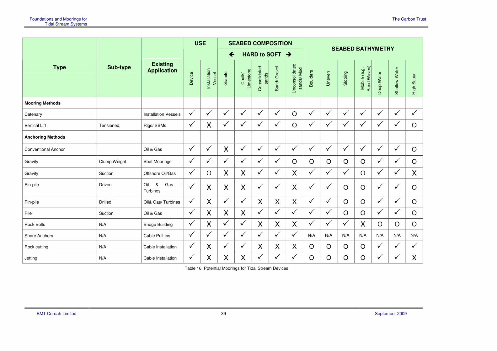
5.2 Potential Foundations and Moorings
A review was made of the foundation and mooring methods identified against the main
characteristics that affect their suitability. This is shown in Table 15 below for foundations
and Table 16 below for moorings. The foundations and moorings are looked at in isolation
in the tables, however they often share common methods for fixing to the seabed and
foundations and moorings may well be used together.
Table Key
���� Suitable O Possible depending on severity X unsuitable

Foundations and Moorings for Tidal Stream Systems
The Carbon Trust
BMT Cordah Limited 37 September 2009
SEABED GEOLOGY
���� HARD to SOFT ����
SEABED BATHYMETRY
Type Sub-type Existing Application
Gra
nite/
Sa
ndsto
ne
Cha
lk/
Lim
esto
ne/
fractu
red
ro
ck
Con
solid
ate
d
san
ds
San
d/ G
ravel
Un
co
nso
lidate
d
sa
nds/ M
ud
Bo
uld
ers
Une
ven
Slo
pin
g
Mob
ile (
e.g
. S
an
d
Wave
s)
Deep
Wa
ter
Sha
llow
Wate
r
Scou
r
Gravity Bases
Gravity Base Offshore ���� ���� ���� ���� ���� O ���� X O ���� ���� O
Gravity Base Caisson Bridges ���� ���� ���� ���� ���� O ���� X O ���� ���� O
Monopiles
Monopile Driven Wind farms X X ���� ���� ���� O O O O X ���� ����
Monopile Drilled Wind Farms ���� ���� X X X O O O O O ���� O
Pin-piled Structures
(templates, quadropods,
tripods etc)
Pin pile Driven Offshore X X ���� ���� O O O O O ���� ���� O
Pin-pile Drilled Offshore ���� ���� X X X O ���� O O X O O
Pin-pile Suction Offshore X X ���� O ���� O ���� O O ���� ���� O
Cable Burial
Rock Cutting Pipeline and cable burial ���� ���� X X X O O O X ���� ���� O
Ploughing Pipeline & Cable burial X X ���� ���� ���� O O O O ���� ���� ����
Jetting Pipeline & Cable burial X X ���� ���� ���� O O O O ���� ���� ����
Novel Ideas
Existing Structure Rig/ Bridge N/A N/A N/A N/A N/A N/A N/A N/A N/A N/A N/A N/A
Natural Features Bridge Building N/A N/A N/A N/A N/A N/A N/A N/A N/A N/A N/A N/A

Foundations and Moorings for Tidal Stream Systems
The Carbon Trust
BMT Cordah Limited 38 September 2009
SEABED GEOLOGY
���� HARD to SOFT ����
SEABED BATHYMETRY
Type Sub-type Existing Application
Gra
nite/
Sa
ndsto
ne
Cha
lk/
Lim
esto
ne/
fractu
red
ro
ck
Con
solid
ate
d
san
ds
San
d/ G
ravel
Un
co
nso
lidate
d
sa
nds/ M
ud
Bo
uld
ers
Une
ven
Slo
pin
g
Mob
ile (
e.g
. S
an
d
Wave
s)
Deep
Wa
ter
Sha
llow
Wate
r
Scou
r
Jack-up Self Propelled/
Dumb
���� ���� ���� ���� ���� O O O O O
���� ����
Semi-submersible Self Propelled/
Dumb
Drilling, pipe laying ���� ���� ���� ���� ���� ���� ���� ���� ���� ���� ���� ����
Tunnel Cut & Cover Road Tunnels O O ���� ���� ���� O O O O O O O
Table 15 Potential Foundations for Tidal Stream Devices
Foundations and Moorings for Tidal Stream Systems
The Carbon Trust
BMT Cordah Limited 39 September 2009
SEABED COMPOSITION USE
���� HARD to SOFT ���� SEABED BATHYMETRY
Type Sub-type Existing
Application
Devic
e
Insta
llation
Vessel
Gra
nite
Chalk
/
Lim
esto
ne
Consolid
ate
d
sands
Sand/ G
ravel
Unconsolid
ate
d
sands/ M
ud
Bould
ers
Uneven
Slo
pin
g
Mobile
(e.g
.
Sand W
ave
s)
Deep W
ate
r
Shallo
w W
ate
r
Hig
h S
cour
Mooring Methods Catenary Installation Vessels � � � � � � O � � � � � � �
Vertical Lift Tensioned, Rigs/ SBMs � X � � � � O � � � � � � O
Anchoring Methods
Conventional Anchor Oil & Gas � � X � � � � � � � � � � O
Gravity Clump Weight Boat Moorings � � � � � � O O O O O � � O
Gravity Suction Offshore Oil/Gas � O X X � � X � � � O � � X
Pin-pile Driven Oil & Gas -
Turbines � X X X � � X � � O O � � O
Pin-pile Drilled Oil& Gas/ Turbines � X � � X X X � � O O � � O
Pile Suction Oil & Gas � X X X � � � � � O O � � O
Rock Bolts N/A Bridge Building � X � � X X X � � � X O O O
Shore Anchors N/A Cable Pull-ins � � � � � � � N/A N/A N/A N/A N/A N/A N/A
Rock cutting N/A Cable Installation � X � � X X X O O O O � � �
Jetting N/A Cable Installation � X X X � � � O O O O � � X
Table 16 Potential Moorings for Tidal Stream Devices

Foundations and Moorings for Tidal Stream Systems
The Carbon Trust
BMT Cordah Limited 40 September 2009
5.3 Further Information on Foundation Types
The table (Table 15 above) shows the most common type of foundations available as well
as some unconventional possibilities. It lists the types of foundations available and then
categorises where they are likely to be used with respect to seabed conditions. To make
the table as comprehensive as possible the geology of the seabed has been used as well
as the bathymetric criteria that may impact on foundation suitability.
Seabed Geology
The geology has been graded from hard to soft with typical seabed conditions listed; these
classifications are not intended to be exhaustive but indicative of the type of conditions that
may be present.
Seabed Bathymetry
The bathymetric data indicates whether the seabed is sloping, uneven or strewn with
boulders and also gives and indication of the sea bed stability with respect to sediment
transport, the formation of sand waves and scour; water depth has also been included.
Note: Not all of these factors can be represented by a simple Yes or No as to their
suitability, as varying degrees of these conditions may or may not allow a foundation
system to be used.
Typical Site Conditions
There are two main proposed locations for tidal stream devices, estuarial and open water.
The open water sites tend to be categorised by hard seabed conditions with little or no
sediment cover as the high current speeds tend to prevent and sediment from settling.
In estuarial sites although sediment may be thin at the highest current speeds; at the edges
of the high current areas more sediment may be present and within the scope of mooring
positions and possibly foundation sites.
5.3.1 Gravity Base
Gravity bases can be utilised in various forms and may or may not need to be fixed to the
seabed. In its simplest form a gravity base anchor or foundation will be lowered to the
seabed and its weight will be sufficient to hold the structure in place. In other instances the
base may need to be fixed to the sea bed by the use of piles, grouting or the use of suction
techniques.

Foundations and Moorings for Tidal Stream Systems
The Carbon Trust
BMT Cordah Limited 41 September 2009
5.3.2 Monopile
Monopiles are one of the most common current methods of foundation for wind farms and
are predominately used in sediments such as consolidated sands into which they are piled,
although they can be drilled into harder rocks. They offer a firm foundation to structures
that consist of a mono tower. The drawback of such a method is that they are expensive to
install particularly if drilled and to be economic need to be installed in numbers.
5.3.3 Pin pile
Pin piles are used extensively in the offshore environment and can be driven, drilled or
sucked into position depending on the ground conditions. How the piles are used depends
on their configuration but typically high strength grout will be used to keep the structure in
place or fittings like ball and roller inserts can be used, particularly in mooring applications.
Increased holding power in sands can be gained by the use of ‘bell footing’ where the
bottom of the drilled hole is expanded out and filled with cement. In softer sands an epoxy
can be used to stabilise the sands around the hole.
For tidal applications it is more likely that pin-piles will be drilled due to the nature of the
seabed. Drilling of the sockets can be conducted from the surface through a conductor or
using subsea drilling rigs. Technology from deepwater oilfield developments is enhancing
the ability to develop installation methods for drilling and securing pin piles using subsea
drilling rigs operated automatically from the surface.
The performance of these sub-sea drill has yet to be tried in tidal races but is likely to be a
key area of development and research.
5.3.4 Existing Structure(s)
It may be possible to attach current turbines to existing structures such as bridges, oil
platforms, or even combined with other renewable system such as wind turbines.
5.3.5 Rock Cutting
Rock cutting is a common technique used for the burial of cables and pipelines both
onshore and offshore in hard ground conditions. The rock cutting machine will cut a trench
to about 2m depth and about 200-300mm wide, for cables, but this could be modified for
other applications. Once a trench has been cut, anchoring devices could be inserted in the
trench. This would only be suitable for multiple devices as the deployment of rock cutting
machinery is expensive, but once deployed can be quick to cut the trenches. This would
require more research into the types of anchoring devices that could be used.

Foundations and Moorings for Tidal Stream Systems
The Carbon Trust
BMT Cordah Limited 42 September 2009
5.3.6 Ploughing
Ploughing produces the same profile as rock cutting but is used in softer sea bed
conditions.
5.3.7 Jetting
Jetting can be used in consolidated sediments or lighter soils. Jetting is commonly used in
post lay cable and pipeline burial and is used to undermine whatever is buried by
fluidisation of the sediment so that the item sinks once the jetting ceases the sediment then
tends to reconsolidate; could be utilised in increasing the burial depth of anchors to
increase holding power.
Air-lifting is a type of jetting using compressed air through a pipe lowered to the seabed.
The expansion of the air-bubbles as they rise creates a strong suction which will remove
any loose material. This can be used for jetting foundations to the bed rock and the same
connections can then be used for grouting thereby ensuring the foundation is grouted to the
bed-rock.
5.3.8 Natural Features
Natural features such as rock faces may be used in estuarial sites provided they do not
interfere with navigation and other marine activities. There is also the possibility of anchors
being located on or above the shoreline, which would reduce installation and maintenance
costs.
5.3.9 Jack-up
Jack-up rigs are commonly used for the installation of wind turbines; a simplified purpose
built structure could be used as a platform on which to mount current turbines. This means
that rather than being a method of installation the Jack-up it self becomes the foundation for
the turbines. Issues such as vortex induced vibration, survival air gaps and the leg footings
would need to be addressed.
5.3.10 Semi submersible- SWATH (Small Waterplane Area Twin Hull)
Semi submersible / SWATH technology could be used as a platform to deploy current
turbines. The vessel would need to be simplified, but it would only make sense if other
systems were impractical or more expensive due to site conditions. The semi- submersible
would be permanently moored and would then become the platform from which the turbines
were deployed. This application is commonly used for drilling platforms and
accommodation rigs in deeper waters such as the North Sea. Swath technology is

Foundations and Moorings for Tidal Stream Systems
The Carbon Trust
BMT Cordah Limited 43 September 2009
increasingly used in smaller high speed ferries, pilot vessels and is being considered for
wind farm support vessels.
5.3.11 Tunnel
An increasingly common method of tunnelling under rivers is to excavate a trench and then
sink pre-cast concrete sections into place. This technique could be modified to install
concrete bases for turbines although it is unlikely to be economical unless several turbines
were to be installed.

Foundations and Moorings for Tidal Stream Systems
The Carbon Trust
BMT Cordah Limited 44 September 2009
5.4 Further Information on Moorings Types
The table (Table 16 above) shows the most common type of moorings available as well as
some unconventional possibilities.
The most common application for moorings will be for devices which are designed to be
positioned in mid-water column or at the surface; the devices are likely to be positively
buoyant using the vertical tension component of the moorings to maintain depth clear of the
surface swell and within the optimal tidal stream.
Moorings are characterised by some type of anchor in the seabed with a wire, chain or rope
extending from the anchor to the device. The configuration will be either of the Catenary or
vertical tension type.
Moorings for Installation Vessels
Even if foundations are used there may be a requirement for the installation vessels to be
moored so it is important that both device and installation vessel mooring feasibility are
considered at an early stage of the design.
5.4.1 Catenary
Catenary is the most common type of mooring and is most often used with a range of
anchor types, depending on the holding ground. The anchor is dropped on the seabed and
dragged into place, the anchor embedding as it is dragged, (drag embedment). There is
usually a length of chain or wire attached, which acts as a damper by using the weight of
the wire to create a catenary, keeping the line of pull at the anchor horizontal which is
essential in keeping holding power to a maximum (and preventing uplift at the anchor). The
vertical component of the mooring maintains device depth and allows for heave, while the
horizontal component reduces the footprint of the device. A chain/wire is then shackled to
the wire which goes to the device/ barge. Catenary type mooring systems are also used
with piled, suction and gravity anchors.
5.4.2 Vertical Lift
Vertical lift moorings can be embedment anchor type, gravity base, suction or piled type
and as the name suggests they resist pull out in the vertical direction. These types of
moorings can be installed in almost all types of seabed condition from hard to soft although
vertical lift and suction anchors require adequate penetration to fulfil their holding capability
and as such cannot be used in areas of shallow bedrock or soft sediments. In the case of
shallow bedrock drilled rock sockets would be used in conjunction with suitably designed
pin piles and grouting.

Foundations and Moorings for Tidal Stream Systems
The Carbon Trust
BMT Cordah Limited 45 September 2009
Vertical lift moorings can utilise all types of wires and ropes but are mainly used in a mode
where for larger forces bundled synthetic fibres (Polyester, Dyneema (Polyethylene Fibre or
Nylon) are used. These fibres allow for tensioned moorings such as tension leg platforms
and allow varying degrees of stretch to allow load absorption. The moorings are designed
to be in permanent tension to avoid shock loads.
Synthetic fibre ropes is a rapidly emerging technology, particularly in the oil and gas sector
and in development of wave energy devices, and offers very high strength to weight ratio
and very high fatigue resistance and design life. The increased weight to strength ratio
allows for reduced footprint in the mooring system, which has an impact on the stability of
the device and the power cable connections.
5.4.3 Gravity
Gravity Base Anchors are used for applications requiring vertical lift components. They are
used in oil and gas mooring applications particularly in areas of shallow or surface bed rock
usually for mooring of support vessels.
They are increasingly used in installing wave energy devices. Gravity base anchors can be
installed as a whole or made up of components to reduce lifting requirements. Gravity base
anchors are typically reinforced concrete design but may have skirts, spikes or other
attachments to increase horizontal friction with the seabed.
5.4.4 Pile
Pin piles are commonly used for more permanent moorings, but they tend to cost more to
install. Piles can be either drilled, driven or use suction to be put in place. Drilling is used
in the harder bottom conditions, with piling and suction techniques being used in the softer
sediments. The advantage of suction techniques over piling is that with piling the life of the
pile can be reduced if too much energy is expended in the piling operation. Once a pile has
been placed a mooring structure is then inserted and can be cemented in place or ball and
roller type fittings can be used.
New techniques of subsea drilling for installing piles are emerging, particularly from the
deepwater oil and gas sector. Typically the drill bit and drill string is drilled within the casing
and left to form the pile itself. This technology is likely to become significant in the
development of offshore moorings for wave and tidal devices in hard seabed conditions.
5.4.5 Rock Bolts
Rock bolts are a land based system with many similarities to piling and not used in the
marine environment they tend to be used where the anchoring forces are not high.

Foundations and Moorings for Tidal Stream Systems
The Carbon Trust
BMT Cordah Limited 46 September 2009
5.4.6 Shore Anchors
In some instances the use of anchors on the shore would prove feasible. As an example,
at Strangford Lough in N Ireland, the installation vessel anchors were placed very near the
shore, in retrospect it would have been possible to place these on the shore by piling,
concrete foundation or gravity base. This would have proved cheaper for installation and
for the subsequent maintenance and later recovery. The installation of the anchors would
also have been quicker, not having to rely on good weather and benign tidal conditions.
Shore anchors been used to moor large redundant oil platforms in sea lochs and fjords in
Scotland and Norway and works well in areas such as steep sided fjords or lochs where
drag embedment, piling or other moorings would fail. This has been an issue at the EMEC
tidal site where steep embankments have created problems for mooring installation vessels
using ultra high holding drag embedment anchors.
Consents for shore anchors may be more complicated and may preclude this as an option.
5.4.7 Rock Cutting
Rock cutting is used in cable and pipeline trenching in the marine environment and ashore
but no recorded uses of the technique have been found for marine moorings. However it is
possible that the system could be modified for producing moorings by providing a key into
which an anchoring system could be cemented.
5.4.8 Jetting
Jetting is a technique used commonly in the cable and pipeline industry for post lay burial.
It works in medium to soft sediments by liquefying the sediment below the object to be
buried reducing its bearing capacity and allowing the object to sink into the sea bed. The
sediment returns to its former strength after jetting. This technique could be used in
conjunction with other techniques to increase the depth to which some mooring can be
installed. Air lifting as previously described could also be used.
5.4.9 Ploughing
Ploughing produces the same profile as a rock cutting machine but in sediments rather than
rocks. It is possible that the technique could be used to plough in some type of mooring
system; this would require further research to determine the viability of the method and
show a benefit in terms of cost, time and effectiveness over other tried and tested methods.

Foundations and Moorings for Tidal Stream Systems
The Carbon Trust
BMT Cordah Limited 47 September 2009
5.5 Maintenance of Foundations and Moorings
In general maintenance requirements vary from basic monitoring for fixed foundations for
bottom secured current devices to occasional maintenance for moorings using the tension
type configuration and regular maintenance for the catenary type mooring.
Maintenance requirements need to be offset against the installation costs (cost benefit
analysis) where the costs for fixed foundations tend to be high, tension type moorings high
to moderate, depending on anchor type, and drag embedment relatively cheap.
The maintenance drivers tend to be centred on two main factors:
o do the foundations moorings need to be removed to repair or maintain the device;
o mobility of sediments, scour or mooring lines.
5.5.1 Foundations
Gravity bases and piled foundations and other fixed foundations with the current device
attached directly tend to have little or no movement once installed and require minimal
maintenance other than monitoring of any long term deterioration with respect to local
scour, external impacts, material degradation due to oxidisation or other chemical cause
and build up of marine growth. Inspection regimes for these cases could safely be every 2
or 3 years.
With tension type moorings the anchor point may be piled, a gravity base or a special
anchor with synthetic fibre bundles attached to the current device, the device will be
positively buoyant and will be submerged, the amount of buoyancy determining the vertical
component of the tension in the mooring rope. Modern synthetic fibre moorings such as
Polyester Speedline has a design life in excess of 20 years as long as the rope is not
affected by abrasion or coating damage.
5.5.2 Moorings
Moorings that utilise a catenary pattern will require the most maintenance and require fairly
regular replacement of the anchor wires/ fibres/chains. This is caused by what can be
severe vibration in he wires caused by vortex shedding acting on the wires. Failure of
these lines and attachments is a real possibility.
Failure tends to occur mostly in the thrash zone of the catenary where the catenary meets
the seabed. This causes a large reduction in the design life of the mooring. On oilfield
moorings for structures such as Single Buoy Moorings or FPSOs design fatigue life of chain

Foundations and Moorings for Tidal Stream Systems
The Carbon Trust
BMT Cordah Limited 48 September 2009
moorings can typically be in the region of 2-8 years due to the continual cyclic loads caused
by the thrashing of the mooring in the thrash zone.
Wire catenary mooring would wear quicker than chain and as such is not suitable for
permanent mooring applications. Due to this, synthetic fibre moorings which are tensioned
and do not have a touch down point, are increasingly used and this is very much an
emerging technology that will have applications in the marine renewable energy sector.
If this technology is embraced it is feasible to develop mid water tidal turbine devices with a
good design fatigue life although installation and O&M may be more difficult. It may be
preferable to design the device such that the mooring and flotation elements are fixed and
the turbine attached to the flotation section to avoid the necessity for removing the mooring
system to carry out repair or maintenance on the device.
5.5.3 Power Cable
Consideration must also be given to the power cable. In fixed foundations this is relatively
simple as the cable can be connected to the base and there tends to be no relative
movement, complications will only arise if the cable needs to be disturbed during any
maintenance or repair of the device. The main issue is scour wear and protection of the
cable.
In tethered devices cabling is still reasonably uncomplicated, but again complications will
arise if the cable needs to be recovered in the event of maintenance or repair of the device.
In catenary type moorings motion of the system is inherent in the configuration whether
devices are at the surface or mid-water, it is inevitable that the cable will also move in
relation to the device and the cable configuration will reflect this, in addition the cable will
provide additional forces that will affect the moorings. This will bring additional
complications if the device has to be recovered for maintenance and repair, and may
reduce the life of the cable.
Additionally the nature of the cable suspension in the water column will need to be
designed for the bi-directional tidal forces as well as the heave and footprint of the device
need to be absorbed. This may use Chinese lantern, lazy S configurations or be tethered
to the mooring tendons.

Foundations and Moorings for Tidal Stream Systems
The Carbon Trust
BMT Cordah Limited 49 September 2009
5.6 Conclusions on Foundation and Mooring Methods
5.6.1 Fixed Foundations
In our opinion the most effective method of anchoring a current turbine is to use a fixed
foundation, this obviously favours turbines that can be fixed to the seabed. Although some
novel methods have been tabled, it is our opinion that the tried and tested methods are the
best in the short term.
5.6.2 Mid-water Moored Devices
However, while fixed foundations provide clear advantages several factors may provide
openings for development of more novel designs such as mid-water moored devices. It is
envisaged that patent restrictions, emerging mooring technology and availability of deep
water locations may make moored devices more cost effective.
The emerging development of high technology moorings mid water moored devices may
become a more attractive option. The installation costs can be cheaper and simpler and
the design fatigue life of modern mooring systems can be in excess of 20 years if well
designed. It also allows for optimisation of the height of the device to correspond with the
area of strongest flow.
The major obstacle in the design of a mid-water device is the optimisation of the buoyancy
of the device to counteract the weight of the turbine and provide adequate vertical
component in the mooring line tension. This may restrict the weight and ultimately the
output of the device.
Additional advantages may be the speed with which the devices could be deployed as the
moorings could be rapidly deployed using suitable anchor handling vessels. While these
vessels are expensive, if the installation could be carried out in a short period, this method
may become cost effective.
5.6.3 Effect of Patent Protection
Unlike wave energy devices many of the tidal devices use very similar concepts, they are
effectively variations on a theme. As a result competition and ultimately patent protection
between device developers is common even though there is a desire from all developers for
tidal power as a whole to succeed.
The failure of a key device developer is regarded as being detrimental to the confidence in
the tidal device development as a whole. However, competition for development is intense
and patent protection is likely to be a major issue determining development.

Foundations and Moorings for Tidal Stream Systems
The Carbon Trust
BMT Cordah Limited 50 September 2009
This is in contrast to wave energy developers where the devices have wildly different
concepts and there is a generally less competitive environment and ultimately less patent
restrictions on design of foundations and moorings.
5.6.4 Early Design of Foundations and Moorings
When considering the design of a device it is essential that the method used to position it
within the tidal stream is inherent in the design process. In our opinion too much effort is
expended on the device and not enough on its installation and maintenance, which will
determine the reliability growth and ultimately the devices feasibility as a commercial
generating device. It is the opinion of the authors that the strategy for installation and
maintenance should be a key factor in evaluating the feasibility of a device.

Foundations and Moorings for Tidal Stream Systems
The Carbon Trust
BMT Cordah Limited 51 September 2009
6 INDICATIVE INSTALLATION COSTS
The purpose of this section is to assess the installations costs of a foundation or mooting in
a structured way in order identify the main influences on the costs.
6.1 General
This section looks at the indicative costs of an installation. The cost of an installation is
complex and hinges on many variables; this section has taken the main cost drivers to
indicate the scale of the challenge when planning an installation.
Cost of Single Installations
It should be noted that when installing a single device the mobilisation and demobilisation
costs of the installation can be higher than the rest of the installation costs combined;
therefore the installation of multiple devices brings about real economies with respect to the
cost of installation per device.
Cost of Site Investigations
Site investigations are an integral part of pre and post installation work and are very
expensive particularly if any coring is required. These costs will increase with the depth
below seabed required for analysis i.e. the ultimate depth of the foundations below seabed.
Methods of site investigation to gather seabed hydrographic, geophysical and geotechnical
data vary from surface towed and mounted transducers to coring of the seabed.
Typically core drilling is conducted from a jack up vessel but in deeper water locations, leg
induced vortexing and operational complexities of operating in the tidal races will affect
availability and suitability of vessels for drilling support.
Vibro-coring and Cone Penetration Testing allow for cheaper methods of coring but will be
limited on penetration and core recovery meaning that the only effective method may be to
undertake drilled boreholes through the harder layers and bedrock to the depth of the
foundations. Typically for a drilled/ pin piled location this would be in the region of 5-10m.
Other options for boreholes are drill ships or drilling barges but these are dependant on
suitable mooring systems to reduce footprint to an acceptable level. Typically for
geotechnical drilling from a floating moored vessel in 20m the footprint required is within 2
metres. This increases with depth.
More expensive options are drilling using Dynamically Positioned Vessels but this is likely
to be an extremely expensive option.

Foundations and Moorings for Tidal Stream Systems
The Carbon Trust
BMT Cordah Limited 52 September 2009
Future developments may see the development of seabed mounted subsea geotechnical
drills, which may reduce the requirement for specialised vessels. Ultimately the site
investigation requirements for foundations, particularly piled/drilled foundations, is likely to
be a significant cost driver.
6.2 Cost Bands
In the report all costs are given as cost bands. These bands are defined in Table 17
Installation Cost Bands - Lump Sum Base Costs, Table 18 Installation Cost Bands - Day
Rate Base Costs and Table 19 Installation Cost Bands - Cost Adjustment Factors.
Lump Sum Cost Bands
A B C D E
Lump
Sum
£2M+ £1M - £2M £500K - £1M £100K - £500K £50K - £100K
Table 17 Installation Cost Bands - Lump Sum Base Costs
Day Rate Base Cost Bands
A B C D E
Day
Rate
£50K+ £20K - £50K £10K - £20K £5K - £10K £1k - £5K
Table 18 Installation Cost Bands - Day Rate Base Costs
Cost Adjustment Factors
↑↑↑↑↑↑↑↑↑↑↑↑ ↑↑↑↑↑↑↑↑ ↑↑↑↑ ↔↔↔↔ ↓↓↓↓
+ £100,000’s +£10,000’s + £1,000’s No Effect Decrease
Table 19 Installation Cost Bands - Cost Adjustment Factors

Foundations and Moorings for Tidal Stream Systems
The Carbon Trust
BMT Cordah Limited 53 September 2009
6.3 Installation Vessel Costs
Installation vessel costs are a major driver of installation costs. These costs take the form
of lump sum mobilisation costs and day rate costs. Table 20 below gives an indication of
these costs for a range of typical installation vessels.

Foundations and Moorings for Tidal Stream Systems
The Carbon Trust
BMT Cordah Limited 54 September 2009
Vessel Name Vessel Type Hull Dimensions LxBxD
Crane Capacity Moorings Capability Owner/ operators
Day Rate Cost Band
Capability
Harry McGill Crane Barge 46x16x2.6m 115t capacity 40m boom 6x 20t winches Briggs Marine E Installation of small moorings, cable work
Molly McGill Crane Barge 47x11.3x2 115t capacity 40m boom 4x10t winches Briggs Marine E Installation of small moorings, cable work
Dina M Crane Barge 60x22.4x4 350t Stemat D Installation of Gravity Bases, Construction Support
Svanen Heavy Lift Vessel 102.75x71.80x6 8700t Gantry 8 point mooring Ballast Nedam A Installation of heavy gravity bases, and piled foundations
Missing Link Crane Barge 73.9x21.9x5.5 250t@18m 6point mooring system MCI C Installation of moorings and construction support
Atlas Crane Barge 53.34x20.73x4.25 Crawler crane option 2x 10t triple drum winches Briggs Marine D Installation of moorings and construction support
Microperi Crane Barge 50.50x21.60x4.25 300t@18m 4x25t mooring system MCI C Construction Support
Anna Crane Barge 75.95x23.58x5.50 350t@15m 8x17.5t mooring system MCI C Construction Support
Rambiz Crane Barge 85x44x5.6 max 3300t sheerleg 8 point mooring Scaldis BV A Installation of heavy gravity bases, and piled foundations
Mortlift 1 Crane Barge 43.3x17.6x3.6 68t@ 21.7m 6x10t winches Humber Workboats
E Installation of moorings and construction support
Matador Sheerleg Barge 45.8x20.1x3.6 400t A Sheerleg 6 point mooring Boon Mees B Installation of Gravity Bases, Construction Support
Pontra Maris Multi Purpose Barge 70x20.4x3 Crawler crane option 6 point mooring Stemat C Cable work, site investigation, Construction Support
Fetsy-L Multi Purpose Barge 60.4x11.3x2 Crawler crane option 8 point mooring Stemat C Cable work, site investigation
Lisa A Heavy lift jack up Barge
66x5.46x4 600t@12m 4 point mooring MCI B Heavy lift and piling
Vagant Heavy lift jack up Barge
43.5x22.5x42 Geosea C Construction Support
Excalibur Heavy lift jack up Barge
60x32x4.24 54m boom Seacore C Heavy Lift, Piling and Site Investigation
Seajack Heavy lift jack up Barge
61x76x36 1300t@18m 6 point hydraulic driven A2SEA B Heavy lift and piling

Foundations and Moorings for Tidal Stream Systems
The Carbon Trust
BMT Cordah Limited 55 September 2009
Vessel Name Vessel Type Hull Dimensions LxBxD
Crane Capacity Moorings Capability Owner/ operators
Day Rate Cost Band
Capability
Buzzard Heavy lift jack up Barge
43x30x4.2 6x1 drum Geo@sea C Heavy lift and piling
Resolution Heavy lift jack up Barge
130x38x8 [email protected] MPI offshore B Heavy lift and piling
Table 20 Installation Vessels and their Costs

Foundations and Moorings for Tidal Stream Systems
The Carbon Trust
BMT Cordah Limited 56 September 2009
6.4 Base Case Costs
An estimate has been produced the basic cost parameters for the installation of a single
gravity foundation. This is shown in Table 21.
The table is made up of:
o base costs (both lump sum and day rate);
o cost adjustment factors (factors that can both increase and decrease costs).
6.4.1 Assumptions when Developing the Base Case Costs
The following assumptions were made in developing the base cost:
o Design;
� A gravity base size of 200t.
o Preparation;
� The seabed is relevantly even with no slopes, large boulders or other
obstructions for either the installation vessel or the foundations.
o Location;
� A suitable base port is within 15 nautical miles of the installation site;
� Port operations are not constrained by the tides;
� Small support vessels are available locally;
� That reasonable shore based support industries are available, cranes,
engineering services tool hire etc.;
� Some local skilled tradesmen are available.
o Planning;
� A suitable installation vessel is available;
� Installation takes place in the summer season;

Foundations and Moorings for Tidal Stream Systems
The Carbon Trust
BMT Cordah Limited 57 September 2009
� Weather down time is no more than 4 days per month; (this is quite optimistic
considering additional loads on moorings by tides combined with wind
loadings, generally operations are affected between 15-20kt wind speeds,.
Weather downtime in excess of 50% is more realistic for exposed locations
such as the Pentland Firth. Certain activities may be restricted to Neap tides
where greater tidal working windows are available).

Foundations and Moorings for Tidal Stream Systems
The Carbon Trust
BMT Cordah Limited 58 September 2009
Basic Costs Cost Adjustment Factors (Table 19)
ITEM
Lum
p S
um
(Table
17)
Day r
ate
(Table
18)
Win
ter
Season
Dis
tance to s
ite
No local port
Port
Restr
ictions
Poor
industr
ial
infr
astr
uctu
re
Environm
enta
l
constr
ain
ts
Tid
al C
onstr
ain
ts
Sea-b
ed p
rofile
No o
f devic
es
Incre
ased s
ize
Gravity Base C - ↔↔↔↔ ↔↔↔↔ ↑↑↑↑ ↑↑↑↑ ↑↑↑↑ ↔↔↔↔ ↔↔↔↔ ↑↑↑↑ ↓↓↓↓ ↑↑↑↑↑↑↑↑
Installation Vessel Mobilisation
B C ↔↔↔↔ ↔↔↔↔ ↔↔↔↔ ↔↔↔↔ ↔↔↔↔ ↔↔↔↔ ↔↔↔↔ ↑↑↑↑ ↔↔↔↔ ↑↑↑↑↑↑↑↑↑↑↑↑
Installation vessel
B C ↑↑↑↑ ↔↔↔↔ ↑↑↑↑ ↑↑↑↑ ↑↑↑↑↑↑↑↑ ↑↑↑↑↑↑↑↑ ↑↑↑↑↑↑↑↑ ↑↑↑↑↑↑↑↑ ↓↓↓↓ ↑↑↑↑↑↑↑↑↑↑↑↑
Shore base Rental
E E ↑↑↑↑ ↑↑↑↑ ↔↔↔↔ ↑↑↑↑ ↑↑↑↑ ↑↑↑↑ ↑↑↑↑ ↔↔↔↔ ↓↓↓↓ ↑↑↑↑↑↑↑↑
Mobilisation of Shore Base
D - ↔↔↔↔ ↔↔↔↔ ↔↔↔↔ ↔↔↔↔ ↔↔↔↔ ↔↔↔↔ ↔↔↔↔ ↔↔↔↔ ↑↑↑↑ ↑↑↑↑↑↑↑↑
Shore Personnel
- E ↔↔↔↔ ↔↔↔↔ ↔↔↔↔ ↔↔↔↔ ↔↔↔↔ ↔↔↔↔ ↔↔↔↔ ↔↔↔↔ ↓↓↓↓ ↑↑↑↑
Offshore Personnel
- D ↑↑↑↑ ↑↑↑↑ ↑↑↑↑ ↔↔↔↔ ↔↔↔↔ ↑↑↑↑ ↑↑↑↑ ↑↑↑↑ ↓↓↓↓ ↑↑↑↑
Transport - E ↔↔↔↔ ↑↑↑↑ ↑↑↑↑ ↑↑↑↑ ↑↑↑↑ ↑↑↑↑ ↑↑↑↑ ↑↑↑↑ ↓↓↓↓ ↑↑↑↑
Storage - E ↔↔↔↔ ↔↔↔↔ ↔↔↔↔ ↔↔↔↔ ↔↔↔↔ ↔↔↔↔ ↔↔↔↔ ↔↔↔↔ ↓↓↓↓ ↑↑↑↑
Support Vessels
- D ↑↑↑↑ ↑↑↑↑ ↑↑↑↑ ↑↑↑↑ ↑↑↑↑ ↑↑↑↑ ↑↑↑↑ ↑↑↑↑ ↓↓↓↓ ↑↑↑↑
Cable Installation
- B ↑↑↑↑ ↑↑↑↑ ↑↑↑↑ ↑↑↑↑ ↑↑↑↑ ↑↑↑↑ ↑↑↑↑ ↑↑↑↑ ↓↓↓↓ ↑↑↑↑
Table 21 Indicative Bases Costs and Cost Adjustment Factors of Installing a Foundation

Foundations and Moorings for Tidal Stream Systems
The Carbon Trust
BMT Cordah Limited 59 September 2009
6.5 Commentary on the Cost Adjustment Factors
The following section identifies the cost adjustment factors that could change (i.e. usually
increase) the costs.
6.5.1 Installation During the Winter Season
The time of year that installations are carried out is critical, the accepted season around the
UK for minimising disruption due to poor weather is between April and October; poor
weather can be defined as sea states of >2m and wind speeds in excess of 12m/s, these
represent typical operation parameters for barges and cranes respectively. However, there
are advantages to installing in the winter months if the weather window required to carry out
the installation is short. It is more likely that suitable installation vessels are available and
that the day rate of these vessels will be lower than the summer months. This price
advantage has to be offset against the likelihood that the job will take longer.
In the summer months it will be harder to get vessels on short term charter and the daily
hire costs may well be punitive.
6.5.2 Distance to Site
The further an installation site is from the base of operations the more problems arise in
servicing the requirements of the installation vessel and crew with added costs due to time
delays and additional bunker costs. If the installation vessel has to return to base to load
installation equipment or current devices, then the distance from the base of operations will
play a part in the time required for the installation and hence the cost.
6.5.3 No Local Port
In addition to those drivers mentioned in the previous paragraph having no local base of
operations means that the installation vessel needs to be largely self sufficient and that the
ability of the vessel to stay on station becomes important. This may mean that a larger and
more expensive vessel will be required as well as additional support vessels.
6.5.4 Port Restrictions
The nature of any port may mean that there are restrictions on when vessel can sail, these
may be due to the port having lock access, insufficient water at low tides or priority given to
other commercial traffic.

Foundations and Moorings for Tidal Stream Systems
The Carbon Trust
BMT Cordah Limited 60 September 2009
6.5.5 Poor Industrial Infrastructure
If there is no local infrastructure with respect to the availability of trade skills, and
equipment, these will need to be brought to site and accommodated. This usually means
that costs are considerably increased because men and materials have to kept on hire even
when not needed to ensure availability.
6.5.6 Environmental Constraints
It is quite common for there to be environmental constraints on a project. These can be
restrictions on the time work can be carried out due to migratory birds, marine mammals,
breeding seasons etc or if near land, limits on the amount of noise, particularly with piling
operations. These can potentially have huge cost impacts, particularly if there is any
slippage in a project timescale that then meets these limitations with projects subsequently
being delayed to the next season.
6.5.7 Tidal Constraints
It is axiomatic that there will be operational constraints imposed by the tidal conditions at
the site, the nature of tidal stream devices requiring high tidal currents. However, there
may be additional constraints imposed by local tidal conditions that limit the scope of
operations to more narrow working windows. In addition the higher the tidal stream speed
and additional factors such as wave interaction will increase the size and strength of
foundation required and hence the cost.
6.5.8 Sea-bed Profile
There may be additional factors with the seabed such as steep inclines uneven surfaces,
the presence of large boulders that will necessitate the foundation being modified to suite or
the seabed being prepared before installations can commence.
6.5.9 Number of Devices
If installing only one device the cost per kWh is likely to be high, however by installing
multiple devices, economise of scale will come into play and reduce the cost.
Main cost driver benefits are the spreading of the mobilisation and demobilisation vessel
costs, optimisation of the installation program, ability to negotiate better installation vessel
rates and secure better availability or possibly even develop purpose built installation
capability.

Foundations and Moorings for Tidal Stream Systems
The Carbon Trust
BMT Cordah Limited 61 September 2009
6.6 Conclusions on Installation Costs
Determining the cost of an installation is complicated and entirely dependent on the location
of the installation site, which is not controllable by the installer. Looking at the cost drivers
given in this section it is obvious that the more devices that are installed the less the cost
per unit for installation.
6.6.1 Availability of Vessels
Installation vessels and their availability are another cost factor. The availability of suitable
vessels is poor; most construction vessels have been designed for other industries such as
offshore oil & gas, port construction, dredging and bridge building. These vessels are
designed for industries where the cost of installation is not such a big cost driver and there
are no great imperatives to reduce costs.
6.6.2 Future Availability
The future availability of vessels is also subject to changes driven by factors outside the
control of the tidal industry. This includes the relocation of vessels NW Europe to regions
such as the Caspian and Middle East and the construction of offshore wind farms has
removed many suitable vessels on long term lucrative charters. It is likely that the
development of offshore wind farms will maintain a high demand for suitable support
vessels and that this demand is likely to increase over the next few years with several large
Round 2 offshore wind projects and ultimately the development of the Round 3 projects
absorbing large fleets of support vessels. Strategic consideration of vessel availability is a
key aspect in planning the development of tidal devices, particularly when larger arrays are
proposed.
6.6.3 Resulting Installation Methods
The installation methods of these devices are often dependent on what vessels are
available rather than what would be most suitable. Vessels often need significant
modifications in order to be utilised which drives up the cost of mobilisation and
demobilisation. As the number of installations of these devices increases, more pressure
will be put on vessel availability, and day rates will increase. The only solution to this is for
more suitable vessels to be built; this will not happen commercially unless owners can see
a demand of at least 10 years.
6.6.4 Purpose Built Vessels
Some developers are currently looking at the feasibility of procuring purpose built vessels to
install their devices. Typically new-build or modified barges with lifting capability are being

Foundations and Moorings for Tidal Stream Systems
The Carbon Trust
BMT Cordah Limited 62 September 2009
developed. This is a prudent strategy as the barge can be built or modified to the device
installation requirements, notably:
• Improvised mooring arrangements for use in tidal streams;
• Development of installation capability and expertise;
• Improved lifting and handling systems tailored to the device;
• Cable laying and connection capability;
• Operations and maintenance capability.

Foundations and Moorings for Tidal Stream Systems
The Carbon Trust
BMT Cordah Limited 63 September 2009
7 COMPARATIVE COSTS OF FOUNDATION AND MOORINGS INSTALLATION
One of the supplementary questions asked by the Carbon Trust related to the likely
installation and maintenance cost of foundation for a seabed mounted device and the
moorings for a mid stream moored device.
The reason for the question was that there are many more seabed mounted devices being
proposed than mid-stream devices and the Carbon Trust sought information to help decide
if it was worth investigating more mid stream devices.
7.1 Basis of the Costing
The basis of the costing was:
• a nominal 1MW device;
• a capacity factor of 40%;
• a life of 20 years;
• a discount rate of 15%.
The cost of the Foundation hardware and the Mooring hardware was excluded as it will be
device specific, the cost were for the installation and maintenance only.
7.2 Summary of the Findings
The costing was done using the Carbon Trust Cost Estimation Methodology spreadsheet1.
The input data spreadsheets have been provided separately but a summary is shown in the
figure below.
The methodology calculates energy costs per kWh base on a base case, bounded by an
optimistic and a pessimistic assessment. The figure shows a normalised cost of energy for
the base case foundation and the base case mooring.
The values have been normalised so the foundation base case with 7 devices installed and
a discount rate of 15% equates to 1.
1 The Cost Estimation Methodology is based on an excel-based cost collation tool produced to accompany the
report “Cost estimation methodology: The Marine Energy Challenge approach to estimating the costs of energy produced by marine energy systems” B/15992/C001/069 Version 1.0 commissioned by The Carbon Trust and carried out by Entech UK Ltd in May 2006.

Foundations and Moorings for Tidal Stream Systems
The Carbon Trust
BMT Cordah Limited 64 September 2009
The findings show that there is a significant opportunity for mooring devices to be
substantially cheaper than devices on fixed foundations (Figure 1).
Installation Costs
0.00
0.20
0.40
0.60
0.80
1.00
1.20
1.40
1.60
1.80
2.00
0 5 10 15 20 25 30 35 40
Number of Devices Installed
No
rmalis
ed
Co
st/
kW
h
Foundation - Base (Normalised)
Mooring - Base (Normalised)
Figure 1 Normalised Installation Costs
Cost Reduction Profile
The cost reduction profile comes from the amortisation of fixed costs (such as mobilisation) over the number if devices installed. It does not include any aspect of cost reduction resulting from technological advances, cost of capital or the economies of scale of larger projects.
Absolute Values
The absolute cost for installation are in the range 10 to 38 pence per kilowatt-hour. These
cost should be used with considerable care. The reality is that costs can only be estimated
after an installation method statement has been produced and such statements will be
device and location specific.

Foundations and Moorings for Tidal Stream Systems
The Carbon Trust
BMT Cordah Limited 65 September 2009
Relative Values
The calculations show that the cost of a mid water mooring compared with a foundation is
similar for the optimistic case but foundation devices are significantly more expensive for
both the pessimistic and base cases.
The reason for this is that the installation of heavy and large single foundations requires
significantly larger vessels and therefore significantly larger expense if the vessels are
required for longer.
7.3 Limitations of the Cost Modelling
As mentioned above the installation cost can only really be estimated after device and site
specific method statements have been produced.
The cost of inspection and maintenance of a foundation and/or mooring cannot be
estimated in isolation from the cost of inspection and maintenance of the device. This is
especially the case with a moored device where it may have to be brought in periodically to
maintain the device and this action will also maintain the moorings.

Foundations and Moorings for Tidal Stream Systems
The Carbon Trust
BMT Cordah Limited 66 September 2009
8 CONCLUSIONS
8.1 Integration of Foundation Design with Device Design
The foundation design needs to be an integral part of the device design and not an
afterthought. To make sure this happens there should be a Foundation Requirement
Specification as part of the suite of Device Requirement Specifications.
8.2 Foundation Design - Need to use tried and tested designs
There are a range of foundation options available. In our opinion the tried and tested
foundation methods for marine applications are the best option at this stage, this means
either monopiles or gravity foundations. However, it is important that new and emerging
technologies such as mid water moored devices are not excluded from consideration due to
transfer of mooring technology from the oil and gas sector and limitations imposed by
patents.
8.3 Mooring Design - Need to demonstrate feasibility
There are considerable uncertainties in the use of mid-water moored devices. The
moorings will have to be stable for a long period of time and will have to hold the device
steady in reversing tidal flow. In addition, the tidal range will be significant in proportion to
the depth and therefore there will be considerable change to the mooring and the cable
connection over the tidal cycle. Deep water moored installations, such as Floating
Production, Storage and Offloading (FPSO) vessels do this by “S” bends and in the cables
supported by mid-water buoys, but there will be insufficient depth to do this with tidal
devices. With the emerging technology of tension synthetic moorings, with proven reliability
and fatigue, the use of mid water and moored tidal devices becomes more feasible.
If these devices are to progress then the specification and design of the moorings should be
looked at very carefully, not least because of the problems with connecting cables.
8.4 Installation of Single Devices and Series Installation
The foundation design and the installation concept have to be capable of both single device
installation (to de-risk both the design and the process) and series installation. There are
risks that:
o designing the foundation for a single prototype installation may compromise the ability
to design for the long term economies of scale;

Foundations and Moorings for Tidal Stream Systems
The Carbon Trust
BMT Cordah Limited 67 September 2009
o designing the foundation for the long term economies of scale may compromise the
ability to design for a single installation.
For example if the foundation is designed to take advantage of a specialist vessel then
this vessel might not be available for a single installation.
8.5 Installation Vessels - Need to investigate the “ideal” vessels
The lack of availability of suitable installation vessels is driving up costs and building a
special-to-type tidal stream device installation vessel may reduce costs. Such a vessel
would need to be capable of lifting the types of devices, operating in high tidal currents,
holding on station (and this could mean a jack-up, spud legs, dynamic anchoring or
dynamically positioned vessels) and have facilities for the associated completion works
such as grouting or levelling.
There are a variety of ownership options for such a vessel ranging from pure private sector
ownership, through leading developer long term charter (like the Resolution for wind farms),
government long term charter (like the emergency response tugs held at strategic points
around the coast to help vessels in distress and threatening the coastline) to outright
government ownership (like defence support vessels).
8.6 Maintainability - Need to design for ease of maintainability
Maintainability of a foundation or mooring is crucial to its through life costs. For foundations
the need to carry out inspections, if required, is a major cost driver. Inspection might
require the use of divers (and the devices will be in difficult diving conditions) and the
removal of marine growth (which will be time-consuming in an environment where weather
windows will be short).
For moorings the relaying of moorings will be major cost driver and design should focus on
maintenance without the need to remove moorings.

Foundations and Moorings for Tidal Stream Systems
The Carbon Trust
BMT Cordah Limited 68 September 2009
9 RECOMMENDED ARRAS FOR FURTHER RESEARCH
The following section provides our recommendation for a directed research programme.
9.1 Suggested Research to Reduce Risk
The study identified the following generic risk to tidal device deployment that could be
addressed by the directed research programme.
9.1.1 Risk 01 – Survivability: Survivability of foundations in high tide and storm
environments.
Much testing has been done on the performance of pre-production tidal devices but there
has been less testing of their foundations. As a result there is still considerable uncertainty
on the stability of foundations, particularly over the winter storms.
It is suggested that the testing of foundations is decoupled from the testing of devices and
representative dummy gravity foundations with an appropriate dummy device, say of 250,
500 and 1,000 tonnes, are placed in the Pentland Firth and surveyed for damage and
movement over a period of two years.
The aim of the study would be to gain data on the long term stability of what is expected to
be the most common form of foundation, concrete gravity foundations, quicker and at less
cost and risk than testing functional devices in the same area.
There is an opportunity to install these in May 2009 using the resources that will be
deployed at EMEC to install a test device.
9.1.2 Risk 02 – Cables: Laying, Burying Securing and Connecting Cables in High
Tidal Streams.
All devices will require intra-array and export cables. These have to be laid in areas of high
tidal flow which are often uneven and rocky and survive for 25 years.
It is suggested that research is undertaken to investigate how cables can be laid, buried,
secured and connected in the three main tidal energy areas, the Pentland Firth, the
Anglesey Skerries and Alderney.

Foundations and Moorings for Tidal Stream Systems
The Carbon Trust
BMT Cordah Limited 69 September 2009
The aim of the study will be to give all device and project developers detailed information on
the design of the cable, the installation method and the securing method and also indicative
installation and through life costs.
9.1.3 Risk 03 – High Cost of Installation: Concept Design of a Specialist Vessel.
Current installation concepts are based around the installation of single devices using
existing assets. Larger scale deployment would justify the development of specialist
vessels as large scale development of offshore wind led to specialist vessels.
It is suggested that a an outline design study (or range of designs) of what such a vessel
might look like is produced together with its capital cost and the resulting installation cost.
The study could also look at financing, operating and ownership options. The study should
include options for an installation vessel, a combined installation and maintenance vessel
and a maintenance vessel.
The aim of the study would be to develop design concepts that will reduce the cost of
installation for series installation of a large number of devices.
9.2 Suggested Research to Investigate Opportunities
9.2.1 Opportunity 01 – Mid Water Devices: Feasibility of Mooring Systems.
There are a range of mid water devices proposed that use mooring systems connected to
seabed mounted anchors. These have the potential for significant cost savings but the
feasibility of the mooring system to hold the device in the right position, the alignment over
time and the connection of a cable to a moving device and keeping the cable from being
damaged is uncertain. In particular the resistance of the system to flow induced vibrations
that could result in large movements of the device or vibrations that damage it is uncertain.
It is suggested that a study is undertaken to assess the feasibility of mid water mooring
systems. This could be a theoretical study or a study backed up by water tank testing. The
study should also consider the likely marine growth on the moorings and its effect in the
study.
The aim of the study would be to give all mid-water device developers guidance on
technology available for developing moorings for their device and indicative installation and
through life costs.

Foundations and Moorings for Tidal Stream Systems
The Carbon Trust
BMT Cordah Limited 70 September 2009
9.2.2 Opportunity 02 – Surface Moored Devices: Possible Design Solutions.
There is considerable available technology for mooring passive structures on the sea
surface over long periods of time. FPSOs, SPMs, Drilling and production rigs, Lightships
for example.
It is suggested that a study is undertaken to investigate if devices, currently planned for sea
bed or mid water installation, could be surface mounted and if so what such a system would
look like.
The aim of the study would be to give all device developers information on alternative
installation methods and indicative installation and through life costs.
9.3 Research Programme Participants
The tidal energy industry is driven by the perceived value of its Intellectual Property Rights
(IPR). At the moment device developers see the foundation or mooring system as part of
their developing IPR and will not share information. This means that this type of research
would have to be funded by government (or its agents) and done by an organisation that
does not have equity stake in a tidal stream device. The results would then be
disseminated.
If tidal device developers did not regard the foundations or moorings as IPR then the
research options also include:
o funding a device developer to do the work provided they disseminate the results;
o a joint industry project between device developers, possibly seeded with government
funding;
o funding an installation contractor to do the research provided they disseminate the
results.

Foundations and Moorings for Tidal Stream Systems
The Carbon Trust
BMT Cordah Limited 71 September 2009
10 OBSTACLES ON THE ROUTE TO MARKET
10.1 Routes to Market Template
The following technology and project routes to market templates (Figure 2 & Figure 3) were
used to classify the obstacles identified.
Ability to
Identify
Need
Ability to
Specify
Ability to
Develop
Ability to
Verify
Ability to Show
Benefit
Ability to
Sell
Ability to
Support
Technology Route to Market
Figure 2 Technology Route to Market
Site
Capable
of Gaining
Consent
Weather
Credible
Design
and
Installation
Credible
Operations
and
Maintenance
Project
Capable of
Being
Financed
Project
Capable
of Being
Insured
Power
Purchase
Agreement
Project Route to Market
Figure 3 Project Route to Market
10.2 Conclusions and Directed Research
The following tables (Table 22 & Table 23) show how the conclusions and
recommendations for directed research fit in both the technology and project routes to
market.

Foundations and Moorings for Tidal Stream Systems
The Carbon Trust
BMT Cordah Limited 72 September 2009
Technology Route to Market
Technology Conclusions Directed Research
Ability to identify
need
Ability to specify Integration of Foundation Design
with Device Design
Ability to develop Foundation Design - Need to
use tried and tested designs
Mooring Design - Need to
demonstrate feasibility
Opportunity 01 – Mid Water
Devices: Feasibility of Mooring
Systems.
Ability to verify
Ability to show
benefit
Opportunity 02 – Surface Moored
Devices: Possible Design
Solutions.
Ability to sell
Ability to support
Table 22 Technology Route to Market

Foundations and Moorings for Tidal Stream Systems
The Carbon Trust
BMT Cordah Limited 73 September 2009
Project route to Market
Project Conclusions Directed Research
Capable of
gaining consent
Weather Risk 01 – Survivability:
Survivability of foundations in high
tide and storm environments.
Credible Design
and Installation
Installation of Single Devices
and Series Installation
Installation Vessels - Need to
investigate the “ideal” vessels
Risk 02 – Cables: Laying, Burying
Securing and Connecting Cables in
High Tidal Streams.
Credible
Operations and
Maintenance
Maintainability - Need to design
for ease of maintainability
Capable of being
financed
Risk 03 – High Cost of Installation:
Concept Design of a Specialist
Vessel.
Capable of being
insured
Power purchase
agreement
Table 23 Project Route to Market
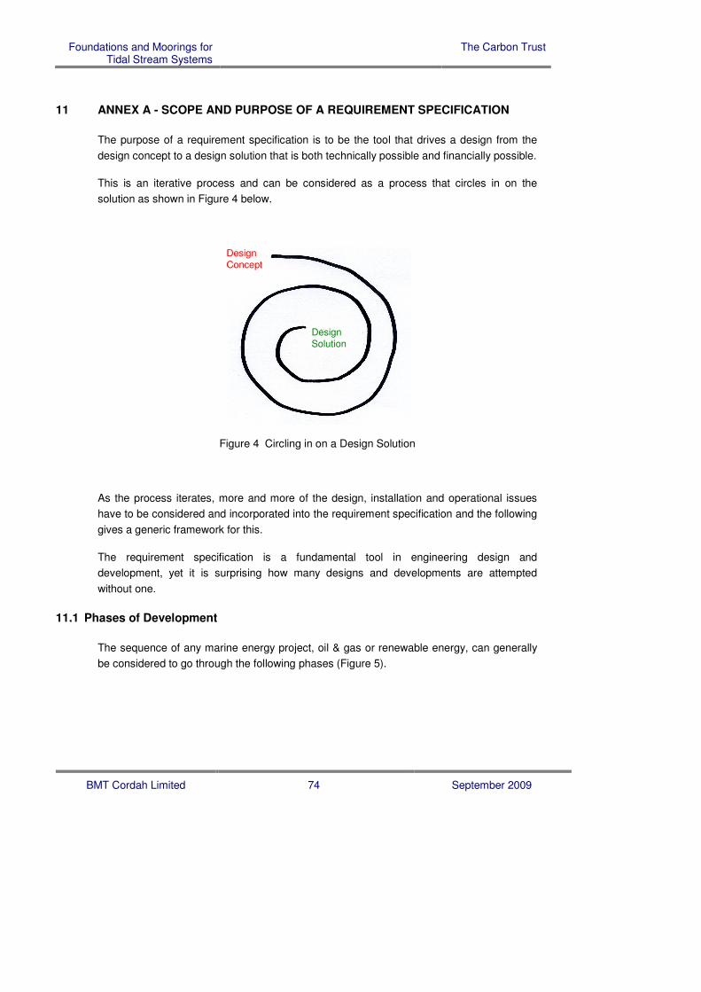
Foundations and Moorings for Tidal Stream Systems
The Carbon Trust
BMT Cordah Limited 74 September 2009
11 ANNEX A - SCOPE AND PURPOSE OF A REQUIREMENT SPECIFICATION
The purpose of a requirement specification is to be the tool that drives a design from the
design concept to a design solution that is both technically possible and financially possible.
This is an iterative process and can be considered as a process that circles in on the
solution as shown in Figure 4 below.
Design
Solution
Design
Concept
Design
Solution
Design
Concept
Figure 4 Circling in on a Design Solution
As the process iterates, more and more of the design, installation and operational issues
have to be considered and incorporated into the requirement specification and the following
gives a generic framework for this.
The requirement specification is a fundamental tool in engineering design and
development, yet it is surprising how many designs and developments are attempted
without one.
11.1 Phases of Development
The sequence of any marine energy project, oil & gas or renewable energy, can generally
be considered to go through the following phases (Figure 5).

Foundations and Moorings for Tidal Stream Systems
The Carbon Trust
BMT Cordah Limited 75 September 2009
Requirement Definition
Concept Design
Design Specification
Design Development
Procurement
Manufacture & Construction
Installation
Commissioning
Operation
Upgrade
Extended Operation
Decommissioning & Disposal
Phases of a Development
Figure 5 Phases of a Marine Development
11.2 Phases of an Installation
The sequence of a marine installation can generally be considered to go through the
following phases (Figure 6).
Disposal of surplus equipment
Off-hire of vessels
all steps have to be reversible
At sea transfer from transport to installation vessels
Installation
Completion
Transit from site- the steps are not necessarily sequential
- there may be parallel steps
- there may be batching of steps
- completion may be separate from installation
Phases of an Installation
Site Preparation
Marshalling of equipment at quayside
Hire of vessels
Loading onto transport/installation vessels
Transit to site
Figure 6 Phases of a Marine Installation

Foundations and Moorings for Tidal Stream Systems
The Carbon Trust
BMT Cordah Limited 76 September 2009
11.3 Installation Cost Drivers
The factors that affect a marine installation, and hence drive the cost, include (Figure 7).
Equipment Sea Conditions Location
weight wind speed and direction nearest ports
size wave height, period and direction nearest vessels
installation tasks current speed transit speeds
task times water depth
access requirements seabed conditions
need for divers daylight and visibility
temperature, rain and lightening
sea ice
Factors Affecting Installation
Figure 7 Installation Cost Drivers
11.4 Phases of Operation
The operation of a marine installation can be considered to include the following stages
(Figure 8).
Operation and control
Routine inspection
Replacement of consumables
Reacting to bad weather
Routine servicing
Investigations
Upgrades
Surveys
Shutdown
Predictive maintenance
Corrective maintenance
Abandonment
Phases of Operation
Figure 8 Phases of Marine Operations

Foundations and Moorings for Tidal Stream Systems
The Carbon Trust
BMT Cordah Limited 77 September 2009
11.5 Factors Affecting Operations
The factors affecting marine operations, and hence drive the cost, include (Figure 9).
Operability Reliability Constraints
manning failure rate access
operational tasks failure effect weather windows
maintenance tasks corrective action transit times
task locations safety
resources staff availability
equipment availability
spares availability
Factors Affecting Operation
Figure 9 Operations Cost Drivers

Foundations and Moorings for Tidal Stream Systems
The Carbon Trust
BMT Cordah Limited 78 September 2009
12 ANNEX B - EXAMPLE ENVIRONMENT IN THE PENTLAND FIRTH
This annex gives some supplementary information on the environment in the Pentland Firth
as an example of one of the harshest environments for tidal energy devices. The
environment has been described in terms of:
o the difficulty of the location;
o the geology;
o the ecology and marine life;
o the propensity for marine growth;
o possible marine growth solutions.
12.1 Difficulty of the Location
The typical sites in the Pentland Firth are in high to very high tidal current, medium to deep
water depth and are exposed. i.e. they are in a very difficult location.
12.1.1 Tidal Currents in the Pentland Firth
There are both strong tidal currents and large spring/neap variations in the Pentland Firth.
Figure 10, Figure 11 and Figure 12 below show the variation in tidal current magnitude over
a spring/neap cycle for a location in the Outer Firth between Stroma and Muckle Skerry.
This data has been derived from the 1km Orkney model developed by POL.
0
0.5
1
1.5
2
2.5
3
3.5
4
4.5
31/03/2004 02/04/2004 04/04/2004 06/04/2004 08/04/2004 10/04/2004 12/04/2004
Date
Cu
rre
nt
sp
eed
(m
/s)
Figure 10 Tidal Currents Cycles in the Pentland Firth

Foundations and Moorings for Tidal Stream Systems
The Carbon Trust
BMT Cordah Limited 79 September 2009
Figure 11 Tidal Currents Cycles in the Pentland Firth - Spring Tide
Figure 12 Tidal Currents Cycles in the Pentland Firth - Neap Tide
Local Conditions
High tidal flow sea areas are likely to have local conditions. The strong tidal currents in the
Pentland Firth give rise to eddies, overfalls and tidal races in a number of locations. These
are areas of turbulence, where current speeds and directions may be highly variable and
consequently may have be avoided as sites for tidal energy devices.
Eddies
Eddies occur in the lee of Swona, Stroma and the Pentland Skerries during both the East
and West setting tide. The location and extent of these may affect currents up to a few
kilometres from the islands. In addition, a large anticlockwise eddy (the Liddel Eddy) forms
between South Ronaldsay and Muckle Skerry on the East flowing stream and an eddy
forms west of Lother Rock (the Lother Eddy) on the North West flowing tide (ebb tide).
Eddies occur off South Walls and Switha in Orkney on the East flowing tide. Smaller and

Foundations and Moorings for Tidal Stream Systems
The Carbon Trust
BMT Cordah Limited 80 September 2009
less consistent weak eddies are also found close to the shore along the Inner Sound of the
Firth.
Tidal Races
Tidal races are found in a number of locations in the Firth. The largest is known as the
Merry Men of Mey and, when fully formed, extends from St. John’s Point on the Scottish
mainland to Tor Ness on Hoy. The Merry Men of Mey race occurs during the west-going
tidal stream, forming off of St John’s Point at the start of the stream, extending across the
Firth when the stream is at full strength and subsiding to mid-channel before disappearing
at the start of the east-going tide.
Another notable tidal race occurs off the North end of Stroma and is named the Swilkie. The
Swilkie persists almost continuously throughout the tidal cycle, and results from the
interaction of the main tidal stream and eddies forming in the lee of Stroma. Races also
form at the southern end of Stroma and on the northern and southern ends of Swona.
In the Inner Sound, a tidal race occurs off of the Ness of Huna and a larger race off the
Ness Of Duncansby during the east-going stream. A smaller, shorter-lived race also occurs
off the Ness of Duncansby during the West going stream.
Other tidal races occur between South Ronaldsay and Muckle Skerry on the east-going
stream (as a result of the interaction between Liddel Eddy and the main tidal stream),
south-west of Lother Rock on the west-going stream and off Brim Ness (Hoy) and Carrick
Head (South Walls) in Orkney.
12.1.2 Water Depths at the Pentland Firth
The water depth in the Pentland Firth location is between 20 and 40 metres.
12.1.3 Exposure of Tidal Devices
The Pentland Firth can be subject to severe storms. This will have an effect on the water
column and hence the loadings on the foundations and moorings. These loads need to be
estimated in order to design the foundation or mooring.

Foundations and Moorings for Tidal Stream Systems
The Carbon Trust
BMT Cordah Limited 81 September 2009
12.2 Geology of the Location
As with many high tidal stream sites there is little seabed sediment and this will preclude
certain types of foundations and moorings.
12.2.1 Bedrock
A high level review of geological information for the Pentland Firth provided by the British
Geological Survey indicates that bedrock geology is dominated by Middle Devonian
sedimentary deposits consisting of Old Red Sandstone and conglomerates.
Old Red Sandstone, in contrast to the typical formations of the Devonian, is largely a
continental formation, laid down in freshwater and on land as a result of the erosion of the
highlands of the Silurian period. This formation is extensive within much of Scotland and
contains a large assemblage of well-preserved fossils, particularly of the Devonian fishes.
Within the Pentland Firth area strata is generally flat-lying which may dip towards the
Atlantic Ocean to the west at approximately 5o. Any loose sediment overlying Old Red
Sandstone is likely to comprise of a thin layer of coarse sand and gravels washed through
the Firth under the influence of strong tidal currents.
12.2.2 Seabed Sediment
It is likely that seabed sediment is thin and in parts, Old Red Sandstone may be exposed.
This consolidated formation is expected to be relatively hard to drill or create piles into,
although not as tough relative to igneous or metamorphic geological conditions.
In addition, the use of trenching techniques for a cable installation phase may not be
possible, due to hard substrate. Further information concerning the thickness and type of
sediment above the Old Red Sandstone is available from the British Geological Survey

Foundations and Moorings for Tidal Stream Systems
The Carbon Trust
BMT Cordah Limited 82 September 2009
12.3 Ecology and Marine Life at the Location
The location is in an area of abundant life.
12.3.1 General
The Orkney archipelago consists of at least 70 islands, 18 of which are inhabited
throughout the year. In contrast, the northern Caithness coastline of approximately 135 km
has a single island, Stroma, which is situated in the Pentland Firth. Tall cliffs, with only a
few small intervening sections of sand and boulder beaches, dominate the remainder of the
northern Caithness coastline. Saltmarsh is rare and largely restricted to small areas at the
mouths of rivers and burns.
12.3.2 Fish
Fish species considered within the scope of this study included Blue Whiting, Norway Pout,
Sole, Mackerel, Plaice and Nephrops, none of which had a sensitive life cycle stage
occurring within the Pentland Firth.
12.3.3 Seabirds
Within the Pentland Firth long sections of the coastline support stacks and skerries,
sandstone cliffs with horizontal bedding and glacial deposits comprising shingle or boulder
beaches. Relatively short sections of sandy shore support locally impressive sand dune
systems, including areas of species-rich coastal grassland. Communities of internationally
important seabirds dominate the faunal interest of the coast: Auks (Guillemot, Puffin,
Razorbill and Black Guillemot), Fulmar, Shag, Arctic Tern and Kittiwake, along with several
large colonies of Storm Petrel. (Pollock et al., 2000) (Clunsten et al, 2001).
12.3.4 Coastal Birds
In winter, there are also important coastal populations of long-tailed duck and Great
Northern Diver. A JNCC survey of Scapa Flow carried out in 1998/99 revealed 600 great
northern divers, the highest wintering population anywhere in Europe. Internationally and
nationally important shorebird populations, such as Turnstone, Purple Sandpiper and
Ringed Plover, are present on beaches along this coastline (Pollock et al., 2000).

Foundations and Moorings for Tidal Stream Systems
The Carbon Trust
BMT Cordah Limited 83 September 2009
12.3.5 Sea Mammals
Within the sea surrounding Orkney, there are internationally important marine mammals
including Otter, Cetaceans (whale and dolphin species) and 38% of the British Grey Seal
and 25% of the Common Seal population. Orkney and the Shetland also have some of the
largest percentages of the total UK population of Harbour Porpoise and Dolphins (Pollock et
al., 2000).
12.3.6 Reptiles
There is also a population of Leatherback Turtle associated with the north east of the study
area which enters Scottish waters at specific times of the year.
12.3.7 Near-shore
Near-shore environments, characterised by steep exposed rock faces and reefs of the outer
coast, support areas of underwater kelp ‘forest’ which shelter a great diversity of other
organisms. More sheltered coastal areas feature sandy or muddy seabed inhabited by
burrowing animals such as Lugworms and Cockles. Sand also covers extensive areas of
seabed offshore which is important for Sand Eels, a food source for fish species such as
Cod, Haddock and Whiting. These fish, especially sand eels, provide essential food for
seabirds and mammals. In more tide-swept conditions such Scapa Flow and areas around
the south of Hoy, sand is often replaced by extensive Maerl beds, a UK Biodiversity Action
Plan habitat (Foster-smith et al, 1993).

Foundations and Moorings for Tidal Stream Systems
The Carbon Trust
BMT Cordah Limited 84 September 2009
12.4 Marine Growth On Foundations and Moorings
There is likely to be marine growth on the foundations and moorings.
12.4.1 Introduction
The purpose of this review is to provide a description of the marine growth that might be
expected to settle on foundations and moorings in the Pentland Firth. There is limited
literature on the extent of marine bio-fouling on tidal devices and no information was
available that could accurately predict the extent and types of fouling expected. The
information below provides an overview of known fouling communities within UK waters and
an estimation of the effect that it will have.
12.4.2 Marine Growth Overview
Subsea structures form artificial reefs which inevitably provide attachment and settlement
sites for marine organisms, unless protected by substantial anti-fouling measures.
Bacteria, algal spores and invertebrate larvae rapidly colonise submerged structures
establishing a ‘bio-fouling’ assemblage (Wolfson et al., 1979).
The marine fouling community is formed by two distinct types of organism: ‘soft’ bodied
organisms such as bacterial biofilms, algae, hydroids, anemones, soft coral, sea squirts and
sponges; and ‘hard’ bodied organisms such as barnacles, tubeworms and mussels (Figure
12). The extent of marine growth colonisation entirely depends on the material of the
subsea structure and the prevailing environmental conditions the structure is subject to.
12.4.3 Process of Marine Growth
The colonisation of a substratum is generally viewed as a four-stage process: biochemical
conditioning of the surface, bacterial colonisation, diatom and protozoan colonisation, and
settlement of larvae and spores (AUMS, 1980). This initial colonising population is
described as the primary fouling community. The climax community is the final stage of
ecological succession. In the case of marine bio-fouling, the climax community is described
as the stable community of organisms including, but not limited to, mussels, barnacles,
anemones and algae. Succession of organisms can be affected when climax communities
are removed, for example by storms. If this occurs, primary communities will re-colonise
the cleaned surface, and ecological succession will re-start.
Barnacles and hydroids are considered to part of the primary fouling community; therefore
settlement occurs on relatively bare surface, after the biofilm has been established. Initial

Foundations and Moorings for Tidal Stream Systems
The Carbon Trust
BMT Cordah Limited 85 September 2009
growth generally occurs rapidly, but slows as other communities of organisms and algae
are established and therefore complete for space and/or food.
12.4.4 Factors Affecting Marine Growth
There are a number of factors that affects the pattern and extent of marine growth on
subsea structures, including: depth of structure, temperature, food availability, competition
and interactions with other organisms and environmental tolerances. As previously
described, the Pentland Firth is influenced by strong tidal currents, leading to areas of
turbulence and highly variable current speeds and directions. These unpredictable
environmental conditions will therefore have an extremely strong influence on the extent
and types of marine growth. Exposure of the surface results in reduced marine growth, and
removal of settled organisms; and scour of surfaces from re-suspended sediments will
affect the viability of fouling communities (Sell, 1992).
12.4.5 Mass of Marine Growth
Marine growth organisms (specifically hard organisms) contribute to the mass of the
structure that they have settled on. Soft bodied organisms have a relative density equal to
1 (Table 24) as they are predominantly made of water. Hard bodied marine growth
organisms comprising of a variety of materials for example calcium carbonate have relative
densities ranging from 1.5 to 2.3. It is therefore possible to make an estimate calculation of
the weight of marine growth on a structure upon completion of a marine growth survey.
Organism Density Factor
Seaweed 1
Hydroids 1
Anemones 1
Soft Coral 1
Mussels 1.5
Tubeworms 2.3
Lophelia pertusa 1.8
Table 24 Density of Marine Growth
12.4.6 Marine Growth on Foundations
The foundation and body of the tidal device would generally be considered as any
stationary part. The stationary surfaces would be expected to accumulate the majority of

Foundations and Moorings for Tidal Stream Systems
The Carbon Trust
BMT Cordah Limited 86 September 2009
the marine growth organisms. Due to the high current velocities within the Pentland Firth, it
is presumed that the marine growth would not form an extensive fouling layer, and that the
type of organisms would be limited. Once the initial biofilm has been established, it would
be expected that recruitment of organisms would consist of barnacles, tubeworms and
mussels.
It is thought that the fouling community would remain as a primary community for an
extensive period of time, due to the high speed currents and re-suspended particles
sloughing off the fouling layers or creating a scenario in which organism larvae is unable to
settle. Mussels are know to settle in multiple layers on stationary surfaces in calm waters,
however, in the Pentland Firth, it would be expected that the mussel growth would be
restricted, resulting in smaller mussels, and in single layers. Brown seaweeds (kelp –
Alaria sp.) may eventually settle, but their growth would be restricted (potentially growing up
to 1 metre maximum), and sea squirts (tunicates) may be able to settle under the body of
the tidal device, depending on the current conditions.
12.4.7 Marine Growth on Mooring Ropes or Wires
The ropes or wires designed to anchor the floating tidal device to the seabed are potential
surfaces for marine growth attachment, although it is unclear as to what will attach in areas
of high current velocity like the Pentland Firth.
It is anticipated that there would be an initial fouling layer consisting of the green algae –
Enteramorpha sp. and hydroids. Mussels are likely to grow on ropes or wires, and possibly
abundantly, although probably not in multiple layers.
Other organisms such as anemones may settle on the ropes if the currents are not
excessive, and again their growth is likely to be restricted.
12.4.8 Marine Growth on Rotating Blades
It is uncertain whether fouling organisms would be able to settle on the rotating and/or
moving parts of the tidal device. The blades of the generators will turn for the majority of
the tidal cycle, allowing seawater to pass through the housing unit, therefore providing a
natural anti-fouling effect.
However, when the blades are stopped, organisms could settle in the form of Enteramorpha
sp., barnacles and tubeworms. Tubeworms and barnacles are able to settle on surfaces
when the water current is less than 2.57 m/s and green algae are able to settle when the
water is less than 6.17 m/s. Another contributing factor is that the surface velocity of the
blades will not be constant over the whole blade.

Foundations and Moorings for Tidal Stream Systems
The Carbon Trust
BMT Cordah Limited 87 September 2009
It may be suggested that the marine growth would occur in a thin layer, would be sparse
over the blade surface and not likely to be consistent, however, it is impossible to predict. If
these organisms are able to settle on the blades, then they are likely to have a significant
impact.
12.4.9 Potential Problems
Unless protected by anti-fouling measures, any structure will become fouled. Excessive
fouling can be problematic when:
• marine growth obscures the underlying structure and therefore impedes visual
inspection;
• seaweeds may get entangled in the blades if they are able to establish in the
housing unit, resulting in the blades being obstructed;
• erosion of the ropes/wires caused by marine growth or abrasion by re-suspended
sediment particles may result in insecurity on stabilising ropes;
• marine growth may add significantly to the weight loading of the structure;
• attached organisms will increase the surface ‘roughness’ of the structure, therefore
increasing the structure’s resistance to water movement, resulting in greater
hydrodynamic loading of the structure;
• marine growth contributes to increased corrosion due to mechanically disrupted
surface coatings; and;
• micro-organisms and sulphate reducing bacteria damage steel and concrete and
decomposing growth may yield acidic products which damage the underlying
surface (AUMS, 1980).
In areas of high current velocity it would be expected that the overall marine growth would
be reduced, however if the currents in the area are reduced or are less than anticipated, the
pattern of marine growth may be different than described above.
In sheltered areas, or areas of lower current velocity, mussels may be able to grow in
multiple layers, significantly adding to the mass of the device, the photic zone (the zone in
which seaweeds are able to grow) would be lower in the water column, possible up to a
depth of 25 m. From about 2 to 3 years after installation soft marine organisms may be
able to settle including anemones and soft corals.

Foundations and Moorings for Tidal Stream Systems
The Carbon Trust
BMT Cordah Limited 88 September 2009
However it would be expected that the soft organisms would not create and blanket cover,
but would instead create a mosaic pattern of growth with the mussels, although it is not
possible to predict which organism would be dominant.

Foundations and Moorings for Tidal Stream Systems
The Carbon Trust
BMT Cordah Limited 89 September 2009
12.5 Anti-Fouling Solutions
A number of anti-fouling solutions are available to reduce the extent of marine bio-fouling of
a submerged structure. A summary of anti-fouling methods which could potentially be used
are detailed below:
o Anti-fouling paints which incorporate biocides that act as contact toxins on the paint’s
surface or dissolve into the boundary layer of seawater surrounding the protected
surface, and are in sufficient concentration to repel, kill or impair the development of
the potential fouling organisms. The majority of anti-fouling paints include copper
compounds as the main biocidal agent, with other compounds as booster biocides.
Self-polishing (or ablative) paints are sophisticated types of anti-fouling paint, where a
copper acrylate polymer is typically used to provide long-life protection (up to circa 7
years) on the hulls of bulk carriers, tankers and other types of ship. The anti-fouling
lifespan depends largely upon the rate at which the surface of the coating reacts with
seawater to form a water-soluble layer. This water-soluble layer then gradually
erodes (‘polishes’) as seawater moves across the surface. This polishing process
sheds any attached fouling and exposes fresh biocide.
o Copper nickel alloy which is incorporated into sheathing (typically as a foil on a non-
conducting backing), as granular or mesh coatings (over non-conducting backing),
and as a structural material. 90/10 copper nickel alloy is normally used. On contact
with seawater, a combination of copper corrosion product and slime-forming marine
bacteria, diatoms and protozoa forms to provide a protective layer on the anti-fouled
surface. This film works as a contact toxin and has self-polishing properties. Copper
nickel could potentially provide a long-life solution;
o Non-toxic methods do not employ biocides, but make the surface unacceptable to the
settling organisms by other means (e.g. by interfering with the adhesion of fouling
organisms, or by removal by abrasion of settling organisms). Surface coatings
include self-polishing paints which do not contain biocides and fouling release (‘non-
stick’) coatings based on silicon elastomer technology. Information on the life-span of
non-toxic methods is limited.
The main issues concerning marine growth and anti-fouling is the inspection and
maintenance of the foundations, moorings and the device. Anti-fouling measures will need
to be regularly inspected, maintained and cleaned (if applicable) to ensure effective and
efficient operation.

Foundations and Moorings for Tidal Stream Systems
The Carbon Trust
BMT Cordah Limited 90 September 2009
12.6 Tidal Current Converter
The table below (Table 25) gives a conversion between m/s and knots and vice versa for
the range of tidal currents expected at the sites.
m/s Knots Knots m/s
0.0 0.00 0.0 0.00
0.2 0.39 0.4 0.21
0.4 0.78 0.8 0.41
0.6 1.17 1.2 0.62
0.8 1.55 1.6 0.82
1.0 1.94 2.0 1.03
1.2 2.33 2.4 1.23
1.4 2.72 2.8 1.44
1.6 3.11 3.2 1.64
1.8 3.50 3.6 1.85
2.0 3.89 4.0 2.06
2.2 4.27 4.4 2.26
2.4 4.66 4.8 2.47
2.6 5.05 5.2 2.67
2.8 5.44 5.6 2.88
3.0 5.83 6.0 3.08
3.2 6.22 6.4 3.29
3.4 6.61 6.8 3.50
3.6 6.99 7.2 3.70
3.8 7.38 7.6 3.91
4.0 7.77 8.0 4.11
4.2 8.16 8.4 4.32
4.4 8.55 8.8 4.52
4.6 8.94 9.2 4.73
4.8 9.33 9.6 4.93
5.0 9.72 10.0 5.14
5.2 10.10 10.4 5.35
5.4 10.49 10.8 5.55
5.6 10.88 11.2 5.76
Table 25 Tidal Current Converter (m/s <-> knots)

Foundations and Moorings for Tidal Stream Systems
The Carbon Trust
BMT Cordah Limited 91 September 2009
13 ANNEX C – ADDITIONAL INFORMATION ON COST MODELLING
13.1 Cost Variability
The methodology calculates energy costs per kWh base on a base case, bounded by an
optimistic and a pessimistic assessment. The figures below (Figure 13 & Figure 14) show
the variation for both the Foundations and the Moorings, normalised as before.
Installation Cost Range - Foundations
0.00
0.20
0.40
0.60
0.80
1.00
1.20
1.40
1.60
1.80
2.00
0 5 10 15 20 25 30 35 40
Number of Devices Installed
No
rmalis
ed
Co
sts
/kW
h
Foundation - Pessimistic (Normalised)
Foundation - Base (Normalised)
Foundation - Optimistic (Normalised)
Figure 13 Normalised Installation Cost Variability - Foundations
Installation Cost Range - Moorings
0.00
0.20
0.40
0.60
0.80
1.00
1.20
1.40
1.60
1.80
2.00
0 5 10 15 20 25 30 35 40
Number of Devices Installed
No
rmalis
ed
Co
sts
/kW
h
Mooring - Pessimistic (Normalised)
Mooring - Base (Normalised)
Mooring - Optimistic (Normalised)
Figure 14 Normalised Installation Cost Variability - Moorings

Foundations and Moorings for Tidal Stream Systems
The Carbon Trust
BMT Cordah Limited 92 September 2009
13.2 Technical Parameters used in the Cost Model
The following technical parameters were used (Figure 15 & Figure 16):
Technical parameters - FoundationsPessimistic Base Optimistic
P B O Comment
P^Dev Peak power for each device Rated or peak power of the device conversion
system, also the gross power before conversion
losses, could be the rating of the generator.
kW
1,200 1,200 1,200
P^Farm Peak power for the farm Rated or peak power of the farm conversion system,
also the gross power before conversion losses.
Could be the product of the number of devices in the
farm and the peak power for each device.
kW
8,400 8,400 8,400
P_Dev Mean power device Annual mean power of the device before conversion
losses.
kW
480 480 480
Assumed capacity factor is 40%. However this is dependent on
matching the power curve of the device to the tidal stream. It could
be as low as 20 to 35%
Capacity Factor 40% 40% 40%
P_Farm Mean power farm Annual mean power of the farm before conversion
losses.
kW3,360 3,360 3,360
Pi Capacity installed for these
cost levels
Assumed cumulative capacity installed by the time
these costs are reached.
kW0 0 0
This does not appear to be used in the calculations
Ni Number of devices installed Assumed cumulative number of devices installed by
the time these costs are reached.
Devices0 0 0
This does not appear to be used in the calculations
Nf Number of farms installed Assumed cumulative number of farms installed by
the time these costs are reached.
Farms0 0 0
This does not appear to be used in the calculations
ND Number of devices in farm Number of individual devices in farm, I.e. the
scaleable part of the farm.
Devices7 7 7
Ds Distance to shore Distance to shore assumed, I.e. length of electrical
connection.
km0 0 0
This does not appear to be used in the calculations
Dm Distance to routine repair base Distance to dock where routine repairs undertaken or
where service vessels are located.
km0 0 0
This does not appear to be used in the calculations
E Annual farm energy capture Net annual energy delivered to point of connection to
the electricity grid including all losses and downtime.
kWh/y
22,781,606 22,781,606 22,781,606
L Design life The design life of the majority of the device. (Some
subcomponents might have shorter lives, we are not
interested initially in these).
years
20 20 20
Early adopted first generation technology is unlikely to have a design life of greater
than 10 years due to obsolescence of technology
XL Transmission efficiency Efficiency of the farm to grid transmission system.90% 90% 90%
Av Device availability Time when device is available to generate whether
wave climate is suitable or not, I.e. time when not
being serviced, or broken.
%
86% 86% 86%
Mature offshore oil and gas installations achieve availability in the range 86% to
96%. It is unlikely that first generation technology will achieve better than oil and
age mature technology.
White - Data Entry Values
Lavender - Interim Calculated Values
Tan - Final Calculated Values
Grey - Unused in this version
Figure 15 Technical Parameters - Foundations
Technical parameters - MooringsPessimistic Base Optimistic
P B O Comment
P^Dev Peak power for each device Rated or peak power of the device conversion
system, also the gross power before conversion
losses, could be the rating of the generator.
kW
1,200 1,200 1,200
P^Farm Peak power for the farm Rated or peak power of the farm conversion system,
also the gross power before conversion losses.
Could be the product of the number of devices in the
farm and the peak power for each device.
kW
8,400 8,400 8,400
P_Dev Mean power device Annual mean power of the device before conversion
losses.
kW
480 480 480
Assumed capacity factor is 40%. However this is dependent on
matching the power curve of the device to the tidal stream. It could
be as low as 20 to 35%
Capacity Factor 40% 40% 40%
P_Farm Mean power farm Annual mean power of the farm before conversion
losses.
kW3,360 3,360 3,360
Pi Capacity installed for these
cost levels
Assumed cumulative capacity installed by the time
these costs are reached.
kW0 0 0
This does not appear to be used in the calculations
Ni Number of devices installed Assumed cumulative number of devices installed by
the time these costs are reached.
Devices0 0 0
This does not appear to be used in the calculations
Nf Number of farms installed Assumed cumulative number of farms installed by
the time these costs are reached.
Farms0 0 0
This does not appear to be used in the calculations
ND Number of devices in farm Number of individual devices in farm, I.e. the
scaleable part of the farm.
Devices7 7 7
Ds Distance to shore Distance to shore assumed, I.e. length of electrical
connection.
km0 0 0
This does not appear to be used in the calculations
Dm Distance to routine repair base Distance to dock where routine repairs undertaken or
where service vessels are located.
km0 0 0
This does not appear to be used in the calculations
E Annual farm energy capture Net annual energy delivered to point of connection to
the electricity grid including all losses and downtime.
kWh/y
22,781,606 22,781,606 22,781,606
L Design life The design life of the majority of the device. (Some
subcomponents might have shorter lives, we are not
interested initially in these).
years
20 20 20
Early adopted first generation technology is unlikely to have a design life of greater
than 10 years due to obsolescence of technology
XL Transmission efficiency Efficiency of the farm to grid transmission system.90% 90% 90%
Av Device availability Time when device is available to generate whether
wave climate is suitable or not, I.e. time when not
being serviced, or broken.
%
86% 86% 86%
Mature offshore oil and gas installations achieve availability in the range 86% to
96%. It is unlikely that first generation technology will achieve better than oil and
age mature technology.
White - Data Entry Values
Lavender - Interim Calculated Values
Tan - Final Calculated Values
Grey - Unused in this version
Figure 16 Technical Parameters - Moorings

Foundations and Moorings for Tidal Stream Systems
The Carbon Trust
BMT Cordah Limited 93 September 2009
13.3 Technical Parameters used in the Cost Model
The following cost parameters were used (Figure 17 & Figure 18). All costs are normalised with the capital cost of the foundation base case with 7 devices installed equal to 1.
Cost parameters - FoundationsPessimistic Base Optimistic
P B O Comment
Cs Structure Cost of main structure. £k 0 0 0 Device structure excluded from estimate
Cm Foundations/moorings Cost of all foundations, anchors or moorings. £k 1 0 0 Step 2 - Cost to procure foundation hardware
Cost of individual foundations, anchors or moorings £k 0.105 0.070 0.040
Ci Control/instrument Control and monitoring instruments. £k 0 0 0 Control and monitoring excluded from estimate
Cpto Power Take-off Power Take-Off costs including all mechanical and
electrical components.
£k0 0 0
Power take off excluded from estimate
Cgc Grid connection Grid connection. £k 0 0 0 Grid connection excluded from estimate
Cisv Installation surveys Surveys. £k0 0 0
Step 1 - Cost to Survey Site
Note: Could be circa 4 times as expensive if a geophysical survey is required for
a piled/drilled foundation
Survey Mobilisation and Demobilisation Cost £k 0.003516 0.003516 0.003516
Survey Cost Per Device Location £k 0.002109 0.002109 0.002109
Cis Installation of structure Installation of the structure (including hire of vessels). £k0 0 0
Step 4 - Cost of installation of the device
Installation Mobilisation and Demobilisation Cost 0.070311 0.049218 0.024609
Installation Cost per Device 0.040429 0.028124 0.014062
Cim Installation of foundations/mooringInstallation of the mooring (including hire of vessels). £k1 0 0
Step 3 - Cost to install foundations or moorings
Installation Mobilisation and Demobilisation Cost 0.105 0.053 0.035
Installation Cost Per Foundation 0.088 0.027 0.015
Cig Installation of grid connection Installation of the grid connection from farm to shore
and onshore work (including hire of vessels).
£k0 0 0
Grid connection excluded from estimate
Ccc Commissioning Commissioning of farm. £k 0 0 0 Commissioning excluded from estimate
Co Management and other Management, insurance and other costs. £k 0 0 0 Management excluded from the estimate
Ctotal Capital cost: Total installed £k 1.83 1.00 0.56
Opm Planned maintenance Planned maintenance and inspection. £k/annum0 0 0
Step 5 - Cost to maintain the Foundations/Mooring
Note: Concrete foundations require minimal maintenance
Maintenance cost per device £k/annum 0.000158 0.000105 0.000105
Omc Monitoring/Control Monitoring/Control of energy production and condition
monitoring.
£k/annum0 0 0
Monitoring and control excluded from estimate
Our Unscheduled repair Unscheduled repair. £k/annum 0 0 0Step 6 - Cost to repair the Foundations
Note: Concrete foundations require minimal repair
Repair cost per foundation £k/annum 0.000158 0.000105 0.000105
Or Rent Rent, both land and sea. £k/annum 0 0 0 Rent excluded from estimate
Oins Insurance Insurance. £k/annum 0 0 0 Insurance excluded from estimate
Ototal Operating costs: total annual £k/annum 0.002215 0.001477 0.001477
Dtotal Total decommissioning costs Incurred after project life has ended. £k Decommissioning excluded from the estimate
White - Data Entry Values
Lavender - Interim Calculated Values
Tan - Final Calculated Values
Grey - Unused in this version
Figure 17 Cost Parameters - Foundations
Cost parameters - FoundationsPessimistic Base Optimistic
P B O Comment
Cs Structure Cost of main structure. £k 0 0 0 Device structure excluded from estimate
Cm Foundations/moorings Cost of all foundations, anchors or moorings. £k 0 0 0 Step 2 - Cost to procure mooring hardware
Cost of individual foundations, anchors or moorings £k 0.042 0.035 0.028
Ci Control/instrument Control and monitoring instruments. £k 0 0 0 Control and monitoring excluded from estimate
Cpto Power Take-off Power Take-Off costs including all mechanical and
electrical components.
£k0 0 0
Power take off excluded from estimate
Cgc Grid connection Grid connection. £k 0 0 0 Grid connection excluded from estimate
Cisv Installation surveys Surveys. £k0 0 0
Step 1 - Cost to Survey Site
Note: Could be circa 4 times as expensive if a geophysical survey is required for
a piled/drilled foundation
Survey Mobilisation and Demobilisation Cost 0.003516 0.003516 0.003516
Survey Cost Per Device Location 0.002109 0.002109 0.002109
Cis Installation of structure Installation of the structure (including hire of vessels). £k0 0 0
Step 4 - Cost of installation of the device
Installation Mobilisation and Demobilisation Cost 0.043944 0.014941 0.014941
Installation Cost per Device 0.019336 0.007910 0.007910
Cim Installation of foundations/mooringInstallation of the mooring (including hire of vessels). £k0 0 0
Step 3 - Cost to install moorings
Installation Mobilisation and Demobilisation Cost 0.035156 0.021093 0.021093
Installation Cost Per Mooring 0.020214 0.014941 0.012304
Cig Installation of grid connection Installation of the grid connection from farm to shore
and onshore work (including hire of vessels).
£k
0 0 0
Grid connection excluded from estimate
Ccc Commissioning Commissioning of farm. £k 0 0 0 Commissioning excluded from estimate
Co Management and other Management, insurance and other costs. £k 0 0 0 Management excluded from the estimate
Ctotal Capital cost: Total installed £k 0.67 0.46 0.39
Opm Planned maintenance Planned maintenance and inspection. £k/annum0 0 0
Step 5 - Cost to maintain the Mooring
Maintenance cost per device £k/annum 0.002637 0.001758 0.001758
Omc Monitoring/Control Monitoring/Control of energy production and condition
monitoring.
£k/annum0 0 0
Monitoring and control excluded from estimate
Our Unscheduled repair Unscheduled repair. £k/annum 0 0 0 Step 6 - Cost to repair the Moorings
Repair cost per mooring £k/annum 0.003516 0.001758 0.001758
Or Rent Rent, both land and sea. £k/annum 0 0 0 Rent excluded from estimate
Oins Insurance Insurance. £k/annum 0 0 0 Insurance excluded from estimate
Ototal Operating costs: total annual £k/annum 0.043066 0.024609 0.024609
Dtotal Total decommissioning costs Incurred after project life has ended. £k Decommissioning excluded from the estimate
White - Data Entry Values
Lavender - Interim Calculated Values
Tan - Final Calculated Values
Grey - Unused in this version
Figure 18 Cost Parameters - Moorings

Foundations and Moorings for Tidal Stream Systems
The Carbon Trust
BMT Cordah Limited 94 September 2009
End.