foundation voiding in jointed plain concrete pavements to
TRANSCRIPT
1
Foundation Voiding in Jointed Plain Concrete Pavements
To Appear in ASCE Journal of Engineering Mechanics
Changwei Xu*, David Cebon†
Abstract
Loss of support due to voids underneath concrete slabs can initiate and propagate slab
cracking in jointed plain concrete pavements. This paper investigates the hypothesises that
foundation voiding occurs because of localised plastic deformation of the ‘depressurised’
foundation due to slab curling and repeated application of traffic loads.
Plane strain and three-dimensional (3-D) nonlinear finite element models of the subgrade
foundation are presented. The analysis shows voids underneath concrete slabs usually occur
along the edge of slabs adjacent to the shoulder. The sizes of voids are mainly determined by
foundation properties (cohesion stress and internal friction angle), slab properties, axle loads,
and temperature gradients. Voids along the edge of slabs adjacent to the shoulder lead to high
transverse tensile stresses on the top surface, which may result in ‘top-down’ longitudinal
cracking close to the outer wheel path. These same voids increase the longitudinal tensile
stresses on the bottom surface at the edge of the slabs, which can increase the potential for
‘bottom-up’ transverse cracking at the middle of the slabs.
keywords: Foundation voiding, Slab curling, Premature slab cracking, Depressurised
foundation, Temperature gradient
* Ph.D., Department of Engineering, University of Cambridge, UK, CB21PZ. Email:
[email protected] † Professor, Department of Engineering, University of Cambridge, UK, CB21PZ (corresponding
author). Email: [email protected]

2
Introduction
Nearly all design procedures for jointed plain concrete pavement (JPCPs) assume that the
subgrade foundation is consistently uniform. It is often modelled as a set of equivalent elastic
springs (e.g. Winkler model). This assumption appears reasonable in the early stages of
pavement life. Nonetheless, many studies have demonstrated that voids underneath slabs may
exist through the service life of JPCPs (Crovetti and Darter 1985; Van 1985). The occurrence
of voids can initiate and accelerate other forms of damage (e.g., slab cracking, faulting) and
eventually reduce the service life (Xie 2013) .
For many years, considerable efforts have been made to understand the mechanisms of
foundation voiding underneath concrete slabs in JPCPs. Pumping, freeze-thaw and
consolidation of soil are traditionally deemed to be three major causes of foundation voiding
below pavement surface (American Concrete Pavement Association 1994; Bhatti et al. 1996;
Ruiz et al. 2005). These processes are summarised below:
a) The erosion of subgrade and/or granular-base material through ‘pumping’ has been
identified in a number of experimental projects, such as the American Association of
State Highway Officials (AASHO) road test in the late 1950s (Bhatti et al. 1996).
When concrete slabs deform under the tyre forces of heavy vehicles, water that has
infiltrated the subgrade (through joints and cracks) will be pumped out at a high
speed, carrying base or subgrade material particles with it. This, in turn, creates a void
or reservoir in which more water can accumulate. Repeated slab deflections enlarge
the void and the concrete slabs gradually become partially unsupported (Bhatti et al.
1996; Hansen et al. 1991). Pumping is determined by many factors, such as water

3
infiltration, traffic loading, the properties of slab and base, and drainage conditions
(Van 1985; VanWijk et al. 1989).
b) Seasonal freeze-thaw cycles can aggravate the effect of water ingress on subgrade
support in cold regions (Ruiz et al. 2005). During the winter months, freezing water
can stiffen and expand the subgrade soil due to ice bonding of soil particles and ice
lens formation. During the subsequent thaw cycle in the spring, the bearing capability
of subgrade soil may be substantially decreased. Under such conditions, subgrade soil
can erode and be pumped out at a faster rate. This can cause sudden dramatic failures
of pavement structures during the spring thaw (Simonsen and Isacsson 1999).
c) Soil consolidation is a natural process of expulsion of water when saturated soil is
compacted by repeated traffic loads. In the consolidation process, soil particles are
packed together more tightly, therefore reducing the volume. A study by American
Concrete Pavement Association (1994) shows that voids can be caused by the
compaction of base material underneath the concrete slabs under repeated heavy truck
loads (American Concrete Pavement Association 1994).
Water is a necessary factor in the above three mechanisms of void formation.
The photographs in Fig. 1 are selected from two different Specific Pavement Studies (SPS),
Series 2 (SPS-2) test sections in the US Long Term Pavement Performance Project (LTPP)
for two sites (States). The SPS-2 test sections were new jointed concrete pavements at the
start of the test. All longitudinal cracking in Fig. 1, consists of a continuous single cracks
relatively near to the shoulder. Such longitudinal cracking patterns are presented on many
SPS-2 sites in the LTPP program. They occur across all soil types, shoulder types, and
climatic conditions.

4
Fig. 2 displays details of the crack development in the 0213 LTPP sections for Arizona (04)
and Arkansas (05), respectively. The data was taken from the LTPP InfoPave database
(FHWA 2014). Each figure shows the ‘percentage cracking’ along with recorded snapshots
of the patterns of longitudinal and transverse cracks at various stages in the life of the
pavement. The percentage of longitudinal cracks is defined as the total length of longitudinal
cracks in a test section normalised by the length of the section (33 slabs): 100% corresponds
to a single crack along the entire length of the section. The percentage of transverse cracks is
defined as the total length of transverse cracks normalised by the sum of the widths of all
slabs in the section: 100% corresponds to a single transverse crack across every slab in the
section. Both of these metrics can exceed 100%. As shown in Fig. 2, longitudinal cracking
began in the Arizona sections seven years after construction and in the Arkansas section six
years after construction. In the Arizona pavement, the crack growth process was gradual,
taking 20 years to get to 100%, i.e. a single crack along the whole section. In Arkansas, the
crack growth was much more rapid, with the longitudinal crack growing to 100% in nine
years, at which point transverse cracks began to grow. (The longitudinal crack was repaired
or sealed at 11 years.)
Table 1 summarises the appearance date of edge longitudinal cracking and pumping of nine
test sections using data from the LTPP InfoPave database (FHWA 2014) . Five sections did
not display any pumping, whereas significant edge longitudinal cracking occurred in these
sections. Some pumping appeared in the rest of the sections. In most sections this occurred in
the same year or much later than the appearance of longitudinal cracking. Table 1 shows that
for these sections, longitudinal edge cracking preceded pumping failure rather than vice-
versa.

5
Pumping, soil consolidation and freeze-thaw of soil do lead to the occurrence of voids,
however, the location of the voids caused by these mechanisms is likely to be randomly
distributed underneath concrete slabs, though probably along the edge. This is expected to
result in random surface cracking in concrete pavements rather than an essentially continuous
single longitudinal crack, as seen in Fig. 1 (and many other LTPP sites). In this paper, a new
hypothesis for the mechanism of longitudinal cracking is proposed and tested by numerical
simulations.
A New Hypothesised of Foundation Voiding in JPCPs
Aggregate base and subgrade soil underneath concrete slabs are granular materials, which
generally fail in shear. It is well known that shear deformation of granular materials is
dependent on the effective hydrostatic pressure (Craig 1974; Terzaghi 1996). Consequently,
granular materials become stronger as the confining pressure increases. Based on the field
observation of the LTPP pavement test sections (see Fig. 1 and Table 1), it is hypothesised
that foundation voiding underneath concrete slabs in JPCPs could be caused by slab curl
interacting with wheel loading as described below:
(i) Slabs curl upwards at the edges during the night due to temperature gradients
through their thickness. This reduces the hydrostatic pressure and reduces the shear
strength of the foundation materials (subgrade soil/aggregate base) under lifted areas
of the slab.
(ii) The curled slab is loaded by moving wheel loads and parts of the lifted sections are
pressed back down. The curvature of the slab causes the foundation to be loaded
along a line adjacent to the depressurised area. This means that the granular material
underneath concrete slabs yields easily and is deformed laterally (‘squeezed out of

6
the way’) into the depressurise area. On repeated loading, this creates a void along
the edge of the slab adjacent to the shoulder.
In wet regions, water ingress under the edge of the slab can cause foundation material to be
‘pumped’ out of the voided area to accelerate the voiding and slab cracking process.
However, pumping is not necessary for the hypothesised mechanism to work.
Reloading of the slabs into the newly created void by wheel loads causes high tensile stress
on the surface about 1-2 m in from the edge of the slab, ultimately leading to a longitudinal
crack in that location.
Numerical Model of Void Growth
The Mohr-Coulomb (M-C) model is an elastic-perfectly plastic model that is often used to
characterize the shear failure of granular materials. Yielding occurs when the shear stress
reaches the shear strength (Terzaghi 1996), which is given by:
(1)
Here τ
f is the shear strength under the effective confining pressure σ , C is the cohesion
stress and ϕ is the internal friction angle. Equation (1) is plotted in Fig. 3. It can be seen that
the shear strength τ
f depends on the pressure σ . High values of C and ϕ will lead to a
higher shear strength. When the effective confining stress σ is taken as zero, the shear
strength τ
f is fully determined by the value of cohesion stress C. It is noted that the
parameters C and ϕ are not material constants. They depend on (a) the initial state of the
material (e.g. moisture content, type of particles, packing condition) and (b) drainage
conditions.
τ f = C +σ tanϕ
7
The M-C Model uses a non-associated flow rule in which the potential function is not equal
to the yield function (the angle of friction and the angle of dilation ψ are not equal) and
irreversible change in volume occurs due to shear. The M-C model in ABAQUS uses a flow
potential that has a hyperbolic shape in the meridional stress plane and has no corners in the
deviatoric stress space (Simulia 2011). The use of non-associated plastic flow rule leads to
unsymmetrical stiffness matrices, so an unsymmetric solver must be used in ABAQUS to
avoid convergence problems. Such models are often used to describe the behaviour of
granular materials with both negative and positive dilatancy (Ti et al. 2009). Parameter values
for the foundation model used in this study are given in Table 2.
Plane Strain Model
A two-dimensional plane strain finite element model of a transverse section through the
pavement was created using ABAQUS 6.12 (Simulia, 2011) to examine the void formation
hypothesis described above. The model consisted of a full width linear elastic concrete slab
resting upon a nonlinear foundation (see Fig. 4).
Both slab and foundation were meshed using 4-node plane strain elements (‘CPE4R’).
(Element names such as CPE4R from Abaqus 6.12 are listed in Parentheses () in this section
and the next.) The interface between the slab and foundation was modeled as a ‘surface to
surface’ rigid contact, which specifies the tangential friction behaviour and allows separation
of the two surfaces after contact. The longitudinal slab joint (along the left hand edge of the
slab) was modeled as a set of spring elements (SPRING1) connecting the specified nodes of
the slab to the rigid ground.
8
The material properties of the slab and foundation in the simulation are listed in Table 2. The
paving layer of the shoulder was assumed to have the same material density and thickness as
the concrete slab.
1) The vehicle forces exerted on the slab surface were characterised by ‘single axle, dual
tyres’ (SADT) with 1.8m wheel centre-to-centre spacing. The dual tyre load was
uniformly applied over a 0.7 m width as a strip of applied pressure of . This
pressure was chosen to give the same elastic deflection of the surface as for a 3-D model
with similar parameters and the load applied at mid slab (halfway between the transverse
joints).
2) A temperature gradient across the slab thickness was applied using the predefined field in
Abaqus to achieve the slab curling.
3) The model did not include the detailed geometry of the shoulder. Instead, a vertical
pressure was applied to the surface of the foundation under the shoulder to account for the
weight of the shoulder material above.
Three-Dimensional (3-D) Model
A three-dimensional (3-D) nonlinear finite element (FE) model of a ‘two-layer’ pavement
system was also developed in this project.
As shown in Fig. 5, the elastic concrete slab ( ) was meshed with shell
elements (S4R) and the nonlinear (Mohr-Coulomb) subgrade foundation ( )
was meshed with 3-D brick elements (C3D8R). The dowelled longitudinal and transverse
joints were modelled as a set of shear and bending spring elements (SPRING1) connecting
the specified nodes of the slab to rigid ground. It was assumed that the longitudinal and
transverse joints have the same characteristics. The interface between slabs and subgrade
Pv = 60kPa
4.6m× 4.2m× 0.2m
4.6m× 7.2m×1m
9
soils was modelled as a rigid ‘surface-surface’ contact with tangential friction. The shoulder (
) was assumed to have the same density as the concrete slabs. A vertical
pressure was applied to the surface of the foundation under the shoulder to account for the
weight of the shoulder material above. (The pavement sections in the LTPP SPS-2
experiment have no dowels between the concrete slabs and the shoulder, so the load transfer
was assumed to be zero at this joint.) Fixed boundary conditions were applied to the lateral
and bottom surfaces of subgrade foundation. The material properties are given in Table 2.
Profile of Void Underneath Concrete Slabs
A two-dimensional (2-D) model static analysis of the plane strain model was performed as
follows:
a) Step 1: A temperature gradient was defined across the slab thickness to curl the slab;
b) Step 2: The axle loading was applied to the slab surface;
c) Step 3: All external loads were removed and the residual plastic deformation of the
foundation was recorded.
Fig. 6 plots contours of plastic strain magnitude at the end of Step 2. A significant plastic
deformation was induced in the ‘depressurised’ area below the concrete slab. The localised
plastic deformation of subgrade foundation will lead to a void in this area.
Fig. 7 shows the void profile underneath the concrete slab at the end of Step 3 for three
different temperature gradients:−10℃/� (hotter on the bottom surface, upward
curling); 0℃/� (uniform temperature); 10℃/� (hotter on the top surface, downward
curling).
4.6m× 3m× 0.1m
10
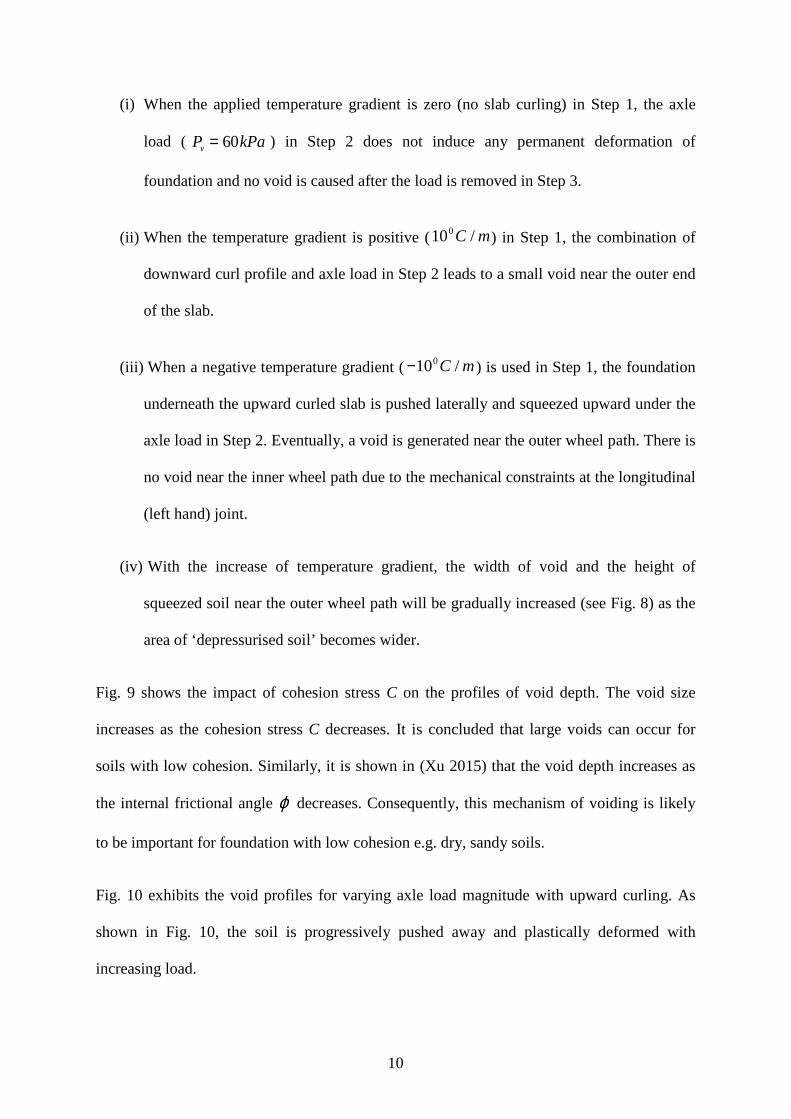
(i) When the applied temperature gradient is zero (no slab curling) in Step 1, the axle
load ( ) in Step 2 does not induce any permanent deformation of
foundation and no void is caused after the load is removed in Step 3.
(ii) When the temperature gradient is positive ( ) in Step 1, the combination of
downward curl profile and axle load in Step 2 leads to a small void near the outer end
of the slab.
(iii) When a negative temperature gradient ( ) is used in Step 1, the foundation
underneath the upward curled slab is pushed laterally and squeezed upward under the
axle load in Step 2. Eventually, a void is generated near the outer wheel path. There is
no void near the inner wheel path due to the mechanical constraints at the longitudinal
(left hand) joint.
(iv) With the increase of temperature gradient, the width of void and the height of
squeezed soil near the outer wheel path will be gradually increased (see Fig. 8) as the
area of ‘depressurised soil’ becomes wider.
Fig. 9 shows the impact of cohesion stress C on the profiles of void depth. The void size
increases as the cohesion stress C decreases. It is concluded that large voids can occur for
soils with low cohesion. Similarly, it is shown in (Xu 2015) that the void depth increases as
the internal frictional angle decreases. Consequently, this mechanism of voiding is likely
to be important for foundation with low cohesion e.g. dry, sandy soils.
Fig. 10 exhibits the void profiles for varying axle load magnitude with upward curling. As
shown in Fig. 10, the soil is progressively pushed away and plastically deformed with
increasing load.
Pv = 60kPa
100C / m
−100C / m
ϕ
11
Apart from magnitude of the axle load, the wheels’ location can also affect the profile of void
depth. When the outer wheel is located closer to the outer edge of the slab, the squeezed soil
will be progressively pushed to the shoulder and the size of the edge void will be enlarged
(Xu 2015).
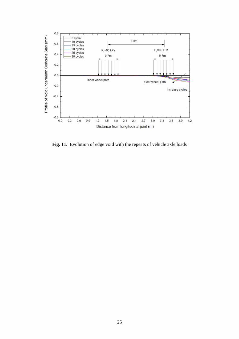
In order to characterise the effect of loading cycles, a repeating triangular pulse load was
used to define the amplitude variations of axle load. Fig. 11 displays the edge void profiles
underneath the concrete slab after several cycles of vehicle axle-loading with upward curling
of the slab. As repeated loads are applied, the edge void depth progressively deepen without a
significant change in width, because the curling profile of the slab doesn’t change. Note that
the increase of void depth per axle pulse is largest for the first load and progressively
decreases with subsequent pulses.
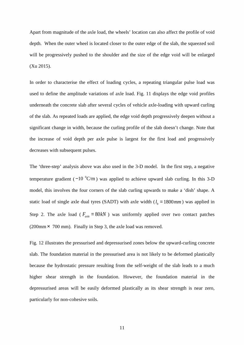
The ‘three-step’ analysis above was also used in the 3-D model. In the first step, a negative
temperature gradient ( ) was applied to achieve upward slab curling. In this 3-D
model, this involves the four corners of the slab curling upwards to make a ‘dish’ shape. A
static load of single axle dual tyres (SADT) with axle width ( ) was applied in
Step 2. The axle load (Faxle = 80kN ) was uniformly applied over two contact patches
(200mm 700 mm). Finally in Step 3, the axle load was removed.
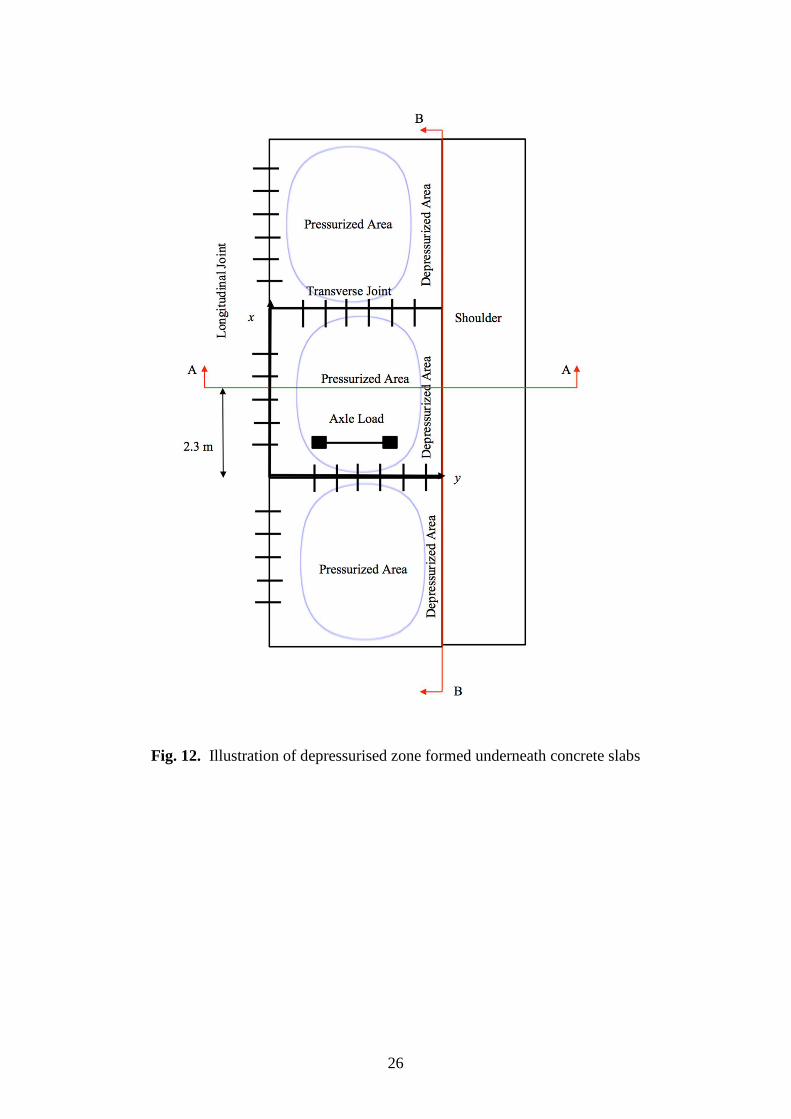
Fig. 12 illustrates the pressurised and depressurised zones below the upward-curling concrete
slab. The foundation material in the pressurised area is not likely to be deformed plastically
because the hydrostatic pressure resulting from the self-weight of the slab leads to a much
higher shear strength in the foundation. However, the foundation material in the
depressurised areas will be easily deformed plastically as its shear strength is near zero,
particularly for non-cohesive soils.
−10 0C/m
lb = 1800mm
×
12
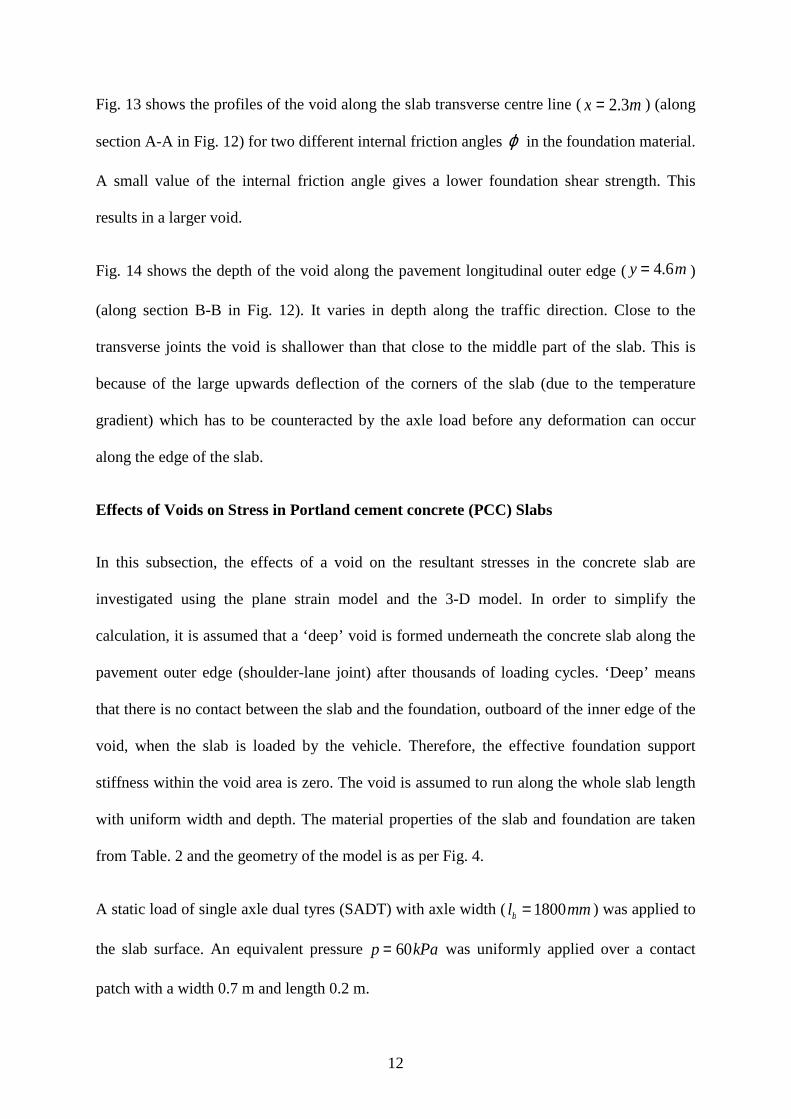
Fig. 13 shows the profiles of the void along the slab transverse centre line ( ) (along
section A-A in Fig. 12) for two different internal friction angles in the foundation material.
A small value of the internal friction angle gives a lower foundation shear strength. This
results in a larger void.
Fig. 14 shows the depth of the void along the pavement longitudinal outer edge ( )
(along section B-B in Fig. 12). It varies in depth along the traffic direction. Close to the
transverse joints the void is shallower than that close to the middle part of the slab. This is
because of the large upwards deflection of the corners of the slab (due to the temperature
gradient) which has to be counteracted by the axle load before any deformation can occur
along the edge of the slab.
Effects of Voids on Stress in Portland cement concrete (PCC) Slabs
In this subsection, the effects of a void on the resultant stresses in the concrete slab are
investigated using the plane strain model and the 3-D model. In order to simplify the
calculation, it is assumed that a ‘deep’ void is formed underneath the concrete slab along the
pavement outer edge (shoulder-lane joint) after thousands of loading cycles. ‘Deep’ means
that there is no contact between the slab and the foundation, outboard of the inner edge of the
void, when the slab is loaded by the vehicle. Therefore, the effective foundation support
stiffness within the void area is zero. The void is assumed to run along the whole slab length
with uniform width and depth. The material properties of the slab and foundation are taken
from Table. 2 and the geometry of the model is as per Fig. 4.
A static load of single axle dual tyres (SADT) with axle width ( ) was applied to
the slab surface. An equivalent pressure was uniformly applied over a contact
patch with a width 0.7 m and length 0.2 m.
x = 2.3m
ϕ
y = 4.6m
lb = 1800mm
p = 60kPa
13
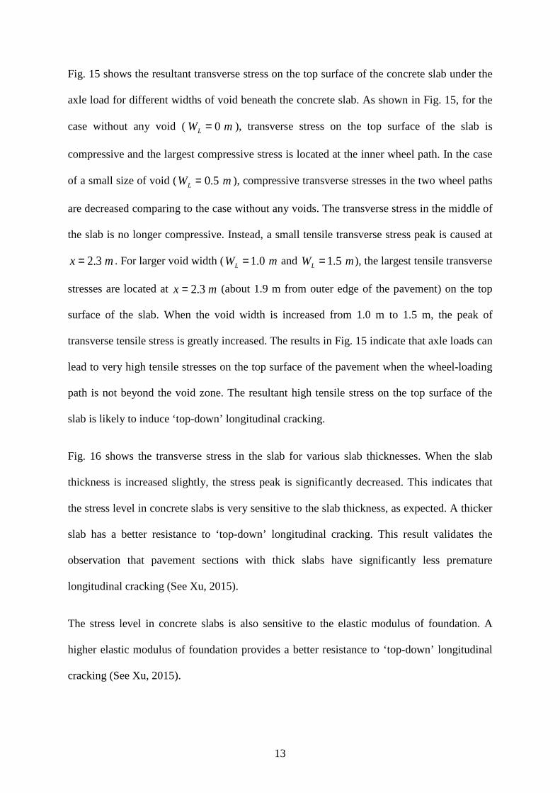
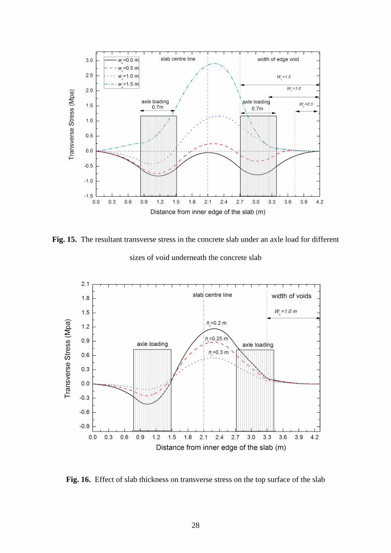
Fig. 15 shows the resultant transverse stress on the top surface of the concrete slab under the
axle load for different widths of void beneath the concrete slab. As shown in Fig. 15, for the
case without any void ( ), transverse stress on the top surface of the slab is
compressive and the largest compressive stress is located at the inner wheel path. In the case
of a small size of void ( ), compressive transverse stresses in the two wheel paths
are decreased comparing to the case without any voids. The transverse stress in the middle of
the slab is no longer compressive. Instead, a small tensile transverse stress peak is caused at
. For larger void width ( and ), the largest tensile transverse
stresses are located at (about 1.9 m from outer edge of the pavement) on the top
surface of the slab. When the void width is increased from 1.0 m to 1.5 m, the peak of
transverse tensile stress is greatly increased. The results in Fig. 15 indicate that axle loads can
lead to very high tensile stresses on the top surface of the pavement when the wheel-loading
path is not beyond the void zone. The resultant high tensile stress on the top surface of the
slab is likely to induce ‘top-down’ longitudinal cracking.
Fig. 16 shows the transverse stress in the slab for various slab thicknesses. When the slab
thickness is increased slightly, the stress peak is significantly decreased. This indicates that
the stress level in concrete slabs is very sensitive to the slab thickness, as expected. A thicker
slab has a better resistance to ‘top-down’ longitudinal cracking. This result validates the
observation that pavement sections with thick slabs have significantly less premature
longitudinal cracking (See Xu, 2015).
The stress level in concrete slabs is also sensitive to the elastic modulus of foundation. A
higher elastic modulus of foundation provides a better resistance to ‘top-down’ longitudinal
cracking (See Xu, 2015).
WL = 0 m
WL = 0.5 m
x = 2.3 m WL = 1.0 m WL = 1.5 m
x = 2.3 m

14
The same approach was used to calculate the resultant surface stresses using the 3-D model.
In order to simplify the calculation, it was assumed that a ‘deep’ void underneath the concrete
slab was formed along the pavement outer edge (shoulder-lane joint) after thousands of
loading cycles. The void was assumed to go along the whole slab length with uniform width (
). Four cases were considered (see Fig. 17):
Case 1: Uniform foundation; outer wheel path located at
Case 2: Voided foundation ( ); outer wheel path located at
Case 3: Uniform foundation; outer wheel path located at
Case 4: Voided foundation ( ); outer wheel path located at
In these four cases, a static load of single axle dual tyres (SADT) with axle width (
) was employed at m (half-way along the slab). The axle load (
Faxle = 80kN ) was uniformly applied over two contact patches area of (700mm 200 mm).
Fig. 18 shows the transverse stress at x=2.1 m on the top surface of the slab under wheel
loads at m for the above four cases. In the cases of uniform foundation (Case 1 and
Case 3), the wheel loads generate a small tensile stress on the top surface of the slab between
the two tyres. However, with an edge void (Case 2 and Case 4), the transverse tensile stresses
caused by the axle wheel loads are greatly increased near the edge of the void, indicating that
the ‘top-down’ longitudinal cracking can be induced under such condition. Although Cases 2
and 4 have the same width of void, the resultant stresses in the two cases are different
because the wheels travel along different paths. When the outer wheel travels along the line
(Case 2), the peak transverse tensile stress occurs at (1.8 m distance
from the pavement outer edge). When the outer wheel travels along the line (Case
WL = 1m
y = 3.1m
WL = 1m y = 3.1m
y = 3.85m
WL = 1m y = 3.85m
lb = 1800mm x = 2.1
×
x = 2.1
y = 3.1m y = 2.4m
y = 3.85m

15
4), the peak of tensile transverse stress occurs at (1.3 m distance from the
pavement outer edge).
Fig. 19 shows the longitudinal stress at x=2.1m on the bottom surface of the slab for the
above cases. In Case 1, the two peaks of longitudinal tensile stress are located at the wheel
paths and they have similar magnitudes. In Case 2, the peak of longitudinal tensile stress at
the outer wheel path is significantly increased. The edge void ( ) has no effect on the
stress peak at the inner wheel path. When the outer wheel travels along the longitudinal
pavement edge (Case 3 and Case 4), a tensile stress will be caused at the slab edge. When
there is an edge void (Case 4) there is a significant increase of the longitudinal tensile stress
peak, which can then contribute to ‘bottom-up’ transverse cracking initiated at the outer edge
of the slab.
Conclusions
The paper presents a new hypothesis of foundation voiding in JPCPs which is supported by
numerical simulation. The location, shape and size of voids underneath slabs are examined,
as are the influences of pavement properties, axle wheel loads and temperature gradients on
the profiles of voids. Finally, the impact of loss of support (due to a deep void) on the
resultant tensile stress in Portland cement concrete (PCC) slabs is studied. The major findings
are summarized as follows:
a) Upward curling of concrete slabs (at night) leads to depressurization of foundation
material adjacent to the shoulder. Voids can occur underneath the edge of the slabs
adjacent to the shoulder, as foundation material is deformed laterally (‘pushed out of
the way’) by downwards deformation of the outer section of the slab due to wheel
loading. Under these conditions, the sizes and rates of growth of voids are mainly
y = 2.9m
WL = 1 m

16
determined by foundation properties (cohesion stress, internal friction angle), slab
properties, stiffness of joints, vehicle axle load, and temperature gradients.
Foundation materials with low cohesive strength are most prone to these mechanisms
of void generation. This means that pavements in dry regions with sandy soils are
likely to display premature longitudinal edge cracking. This agrees qualitatively with
data from the LTPP SPS-2 experiment.
b) Voids along the edge of slabs adjacent to the shoulder lead to high transverse tensile
stresses on the top surface of concrete slabs, which may result in ‘top-down’
longitudinal cracking close to the outer wheel path, 1m to 2m from the outer edge of
the slab. Voids along the edge of the slab adjacent to the shoulder also increase the
longitudinal tensile stresses on the bottom surface of concrete slabs, which can
increase the potential for ‘bottom-up’ transverse cracking at the middle of the slabs.
c) The resultant tensile stresses in concrete slabs are very sensitive to slab thickness. A
small increase of slab thickness can significantly decrease the stress magnitude and
reduce or even eliminate premature slab cracking in JPCPs.
References
American Concrete Pavement Association (1994). "Slab Stabilization Guidelines for
Concrete Pavements." American Concrete Pavement Association.
Bhatti, M. A., Barlow, J. A., and Stoner, J. W. (1996). "Modeling damage to rigid pavements
caused by subgrade pumping." Journal of Transportation Engineering, 122(1), 12-21.
Craig, R. F. (1974). Soil mechanics, E & FN Spon, London.
17
Crovetti, J. A., and Darter, M. I. (1985). "Void detection for jointed concrete pavements."
Transportation Research Record, 1041, 59-68.
FHWA (2014). "LTPP InfoPave." <https://infopave.fhwa.dot.gov/>. (2014).
Hansen, E. C., Johannesen, R., and Armaghani, J. M. (1991). "Field effects of water pumping
beneath concrete pavement slabs." Journal of transportation engineering, 117(6),
679-696.
Ruiz, J. M., Rasmussen, R. O., Chang, G. K., Dick, J. C., and Nelson, P. K. (2005).
"Computer-Based Guidelines for Concrete Pavements. Volume II--Design and
Construction Guidelines and HIPERPAV II User's Manual." The Transtec Group,
Inc., Austin, TX,.
Simonsen, E., and Isacsson, U. (1999). "Thaw weakening of pavement structures in cold
regions." Cold Regions Science and Technology, 29(2), 135-151.
Simulia, D. (2011). ABAQUS 6.12 analysis user's manual, Dassault Systèmes, Providence,
RI, USA.
Terzaghi, K. (1996). Soil mechanics in engineering practice, John Wiley & Sons, London.
Ti, K. S., Huat, B. B., Noorzaei, J., Jaafar, M. S., and Sew, G. S. (2009). "A review of basic
soil constitutive models for geotechnical application." Electronic Journal of
Geotechnical Engineering, 16, 1-18.
Van, W. A. (1985). "Rigid pavement pumping: (1) subbase erosion and (2) economic
modeling: informational report." Joint Highway Research Project, West Lafayette,
IN,.
18
VanWijk, A. J., Larralde, J., Lovell, C. W., and Chen, W. F. (1989). "Pumping prediction
model for highway concrete pavements." Journal of transportation engineering,
115(2), 161-175.
Xie, L. (2013). Modeling and Computation in Engineering II, CRC Press, Boca Raton,
Florida.
Xu, C. (2015). "Performance Modelling of Jointed Plain Concrete Pavements." Doctoral
Thesis, University of Cambridge, Cambridge.

19
(a)
(b)
Fig. 1. The snapshots of single cracking near to the shoulder in the LTPP SPS-2 0213 section
in (a) Arizona (b) Arkansas, from the LTPP InfoPave database (FHWA 2014)

20
(a)
(b)
Fig. 2. The development of cracking in sections 0213 in (a) Arizona and (b) Arkansas

21
Fig. 3. Mohr-Coulomb failure criterion of granular materials
Fig. 4. Plane strain model of the slab and foundation subject to vehicle axle loading

22
Fig. 5. Illustration of the 3-D nonlinear foundation model
Fig. 6. Contours of plastic strain magnitude at the end of Step 2

23
Fig. 7. Profiles of void depth underneath the concrete slab subject to an axle load and various
temperature gradients through slab thickness
Fig. 8. Profiles of void depth underneath the concrete slab subject to an axle load and various
negative temperature gradients through slab thickness

24
Fig. 9. Effect of soil cohesion stress C on the profile of void depth
Fig. 10. Effect of axle loading magnitude with upward curling on the profile of void depth
25
Fig. 11. Evolution of edge void with the repeats of vehicle axle loads
26
Fig. 12. Illustration of depressurised zone formed underneath concrete slabs

27
Fig. 13. Profile of void depth along the slab transverse centre line (section A-A in Fig.12)
after the passage of one axle load, for two values of internal friction angle ϕ
Fig. 14. Depth of the void along the pavement longitudinal outer edge (along section B-B in
Fig.12), as a function of foundation soil friction angle ϕ
28
Fig. 15. The resultant transverse stress in the concrete slab under an axle load for different
sizes of void underneath the concrete slab
Fig. 16. Effect of slab thickness on transverse stress on the top surface of the slab

29
Fig. 17. Illustration of support conditions and wheel locations in the four cases

30
Fig. 18. Transverse stress σ
y on the top surface of the slab at x=2.1m for different wheel
locations and support conditions
Fig. 19. Longitudinal stress σ x
on the bottom surface of the slab at x=2.1 m in different
cases

31
Table 1. Appearance date of longitudinal cracking and pumping in the selected sections of
US Long-term Pavement Performance (LTPP) SPS-2 experimental project
Section NO. Appearance Date of Longitudinal Cracking
(Years From Construction)
Appearance Date of Pumping (Years From Construction)
Arizona (04)-0213 6 No Pumping
Arizona (04)-0262 11 No Pumping
Arkansans (05)-0213 7 8
Colorado (08)-0217 5 15
Colorado (08)-0218 14 No Pumping
North Dakota (19)-0217 11 No Pumping
Iowa (38)-0217 3 5
Ohio (39)-0206 5 5
Washington (53)-0206 9 No Pumping
Table 2. Table of material properties of JPCPs
Material Property Concrete Slab Subgrade Soil Spring Joint Interface
Elastic modulus 2.9e10 Pa 40 MPa
Passion ratio 0.15 0.35
Density 2400
CTE 1.1e5
Cohesion stress 50 Pa
Frictional angle 35° (40°)
Dilation angle 5° (10°)
Shear stiffness N/m2
Bending stiffness N/m
Friction coefficient 0.6
kg/ m3
107
104