foundation report - tracyfoundation report 11th street east tracy overhead tracy, california for...
TRANSCRIPT
FOUNDATION REPORT 11
TH STREET EAST TRACY OVERHEAD
TRACY, CALIFORNIA
For
DRAKE HAGLAN AND ASSOCIATES 11060 White Rock Road, Suite 200
Rancho Cordova, CA 95670
PARIKH CONSULTANTS, INC. 2360 Qume Drive, Suite A
San Jose, CA 95131
(408) 452-9000
March 25th
, 2014 Job No. 2005-151-PSE
DRAFT
TABLE OF CONTENTS PAGE
1.0 SCOPE OF WORK ...................................................................................................... 1
2.0 PROJECT DESCRIPTION ........................................................................................ 1
3.0 EXCEPTIONS TO POLICY ...................................................................................... 2
4.0 FIELD INVESTIGATION AND TESTING PROGRAM ....................................... 2
5.0 LABORATORY TESTING PROGRAM .................................................................. 3
6.0 SITE GEOLOGY AND SUBSURFACE CONDITIONS ......................................... 3 Site Geology................................................................................................................3 6.1
Subsurface Conditions ................................................................................................3 6.2
Groundwater ...............................................................................................................4 6.3
7.0 SCOUR EVALUATION .............................................................................................. 4
8.0 CORROSION EVALUATION ................................................................................... 4
9.0 SEISMIC RECOMMENDATIONS ........................................................................... 5 Seismic Sources ..........................................................................................................5 9.1
Seismic Hazards ..........................................................................................................5 9.2
Liquefaction Potential .................................................................................................5 9.3
Seismic Design Criteria ..............................................................................................6 9.4
10.0 AS-BUILT FOUNDATION DATA ............................................................................ 8
11.0 FOUNDATION RECOMMENDATIONS ................................................................. 8 General ........................................................................................................................8 11.1
Foundation ..................................................................................................................8 11.2
Lateral Pile Capacity .................................................................................................12 11.3
Embankments and MSE Walls .................................................................................14 11.4
11.4.1 Bearing Capacity of MSE Walls ........................................................................ 15
11.4.2 Settlement Under Embankments and MSE Walls.............................................. 15
11.4.3 Embankment Stability ........................................................................................ 17 Traditional Retaining Wall - Retaining Wall No. 5 (Caltrans Standard Type 5) .....18 11.5
12.0 STRUCTURAL PAVEMENT DESIGN .................................................................. 19
13.0 NOTES TO DESIGNER ............................................................................................ 20
14.0 CONSTRUCTION CONSIDERATIONS ................................................................ 20 General ......................................................................................................................20 14.1
Construction of CIDH Concrete Piles.......................................................................20 14.2
Settlement Monitoring ..............................................................................................21 14.3
Demolition of the Existing Foundation.....................................................................21 14.4
15.0 INVESTIGATION LIMITATIONS ......................................................................... 21
REFERENCES ............................................................................................................................ 23
APPENDIX I SITE MAP
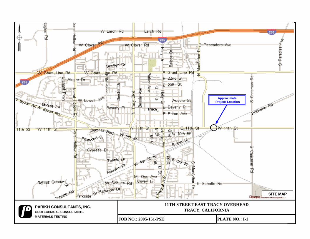
Site Map (Plate I-1)
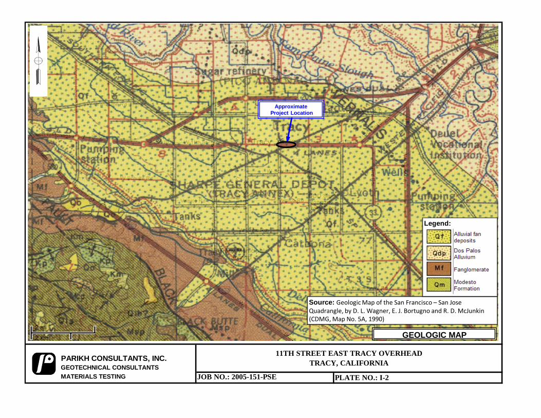
Geologic Map (Plate I-2)
APPENDIX II LOGS OF TEST BORINGS
APPENDIX III FIELD EXPLORATION AND TESTING
APPENDIX IV LABORATORY TEST RESULTS
APPENDIX V ANALYSES AND CALCULATIONS
Fault Map (Plate V-1)
ARS Curves (Plate V-2A thru V-2C)
Liquefaction Analysis Results
Generalized Shear Strength Profile
Pile Capacity
Lateral Spreading Analysis - Compatibility Plots - Slope Stability Analysis - LPILE Analysis Results
MSE Wall Design - Bearing Capacity Calculation for MSE Walls - Settlement Analysis Results - Wick Drain - Slope Stability Analysis Results
Retaining Wall No. 5 - Bearing Capacity Calculation - Settlement Analysis
Pavement Calculation
FOUNDATION REPORT
11TH
STREET EAST TRACY OVERHEAD
TRACY, CALIFORNIA
1.0 SCOPE OF WORK
The scope of work performed for this investigation included a review of the readily available
geologic literature pertaining to the site, obtaining representative soil samples and logging soil
materials encountered in the exploratory borings, laboratory testing of the collected samples,
conducting Cone Penetration Tests (CPT), engineering analysis of the field and laboratory data
and preparation of this foundation report.
The purpose of this report is to evaluate the general soil conditions at the project site, to evaluate
their engineering properties, and to provide foundation design recommendations for the proposed
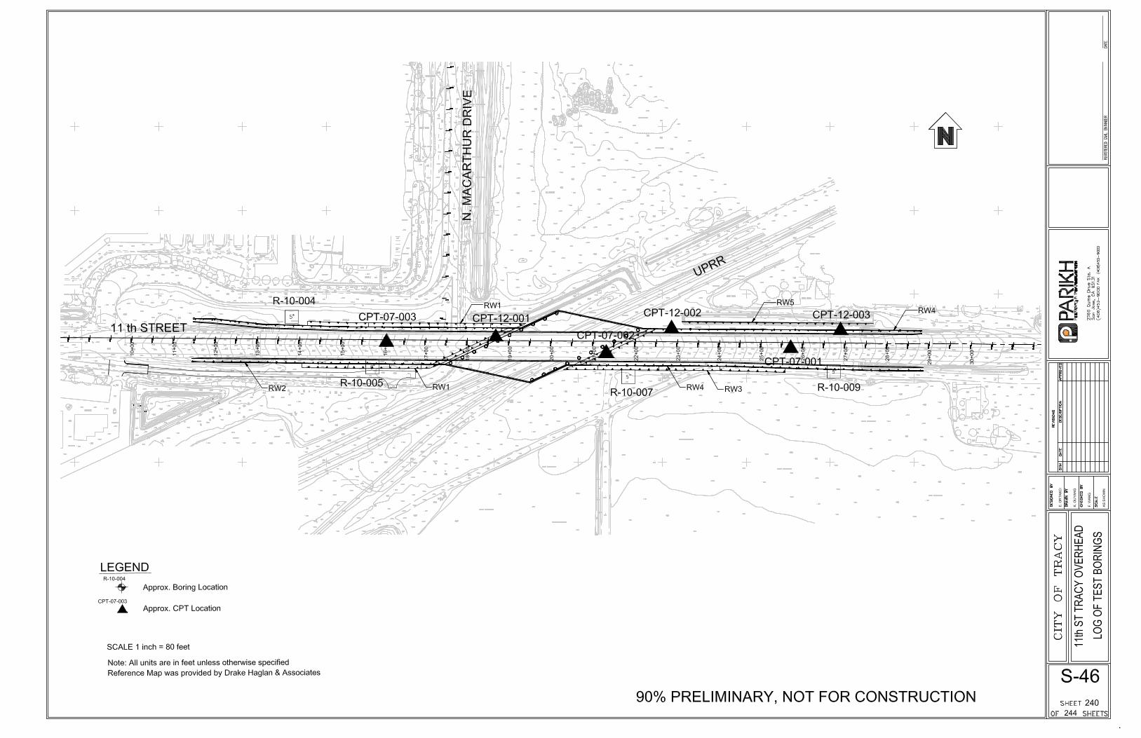
project. The approximate location of the site is shown on the Site Map (Plate I-1) in Appendix I of
the report.
Due to limitations inherent in geotechnical investigations, it is neither uncommon to encounter
unforeseen variations in the soil conditions during construction nor is it practical to determine all
such variations during an acceptable program of drilling and sampling for a project of this scope.
Such variations, when encountered, generally require additional engineering services to attain a
properly constructed project. We, therefore, recommend that a contingency fund be provided to
accommodate any additional charges resulting from technical services that may be required during
construction.
The geotechnical recommendations presented in this report are intended for design input and are
not intended to be used as specifications. These recommendations should not be used directly for
bidding purposes or for construction cost estimates.
2.0 PROJECT DESCRIPTION
The City of Tracy proposes to replace the existing 11th
Street East Tracy Overhead, which crosses
Union Pacific Railroad (UPRR) tracks and North MacArthur Drive in the City of Tracy,
California. The existing overhead is a 34-span structure and was originally built in 1936. The
existing structure consists of reinforced concrete T-beams and steel girders, and the superstructure
is founded on timber piles, but the foundation detail is not available. The bridge was widened in
1960, and the widened portion is supported on steel piles (10BP42).
The project will replace the existing overhead structure with a shorter structure of about 291 feet
long (along centerline) in combination with retaining walls and embankment fill at the approaches.
The replacement structure will provide for a typical section that is about 89 feet wide in order to
accommodate two 12-foot wide through traffic lanes in each direction, 8-foot wide shoulders
which will serve as Class II bicycle lanes, and 8-foot wide separated sidewalks on each side that
are protected with traffic side barriers. Triangular overlook areas are planned on both sides of the
Drake Haglan & Associates
Job No. 2005-151-PSE (11th
Street OH)
March 25th
, 2014
Page 2
structure, and this is resulting from skewing the girders relative to the centerline of the roadway. It
is planned to use large diameter Cast-In-Drilled-Hole (CIDH) piles for foundation support.
A temporary on-site detour will be constructed south of the existing alignment to allow the existing
structure to be removed and the new overhead to be constructed in one stage on the same
horizontal alignment as the existing structure. The temporary detour structure will be about 230
feet long and 30 feet wide. It is also planned to use CIDH piles for foundation support.
Most of the permanent embankment will be supported by two-tiered Mechanically Stabilized
Embankment (MSE) walls with design height up to about 40 feet. Caltrans standard MSE wall
design will be adopted. A short cantilever retaining wall (Caltrans Standard Type 5) is planned
along the northeastern side of the new embankment.
3.0 EXCEPTIONS TO POLICY
Normal procedures were assumed for construction of the bridge structure throughout our analysis
and represent one of the bases of recommendations presented herein. The investigation and design
for the proposed foundations have followed Caltrans policy. Exception to policy is not needed.
4.0 FIELD INVESTIGATION AND TESTING PROGRAM
Three Cone Penetration Tests (CPT) were performed in November 2007 in order to help the
designer to establish the design strategy for the proposed project. During PS&E design phase, four
more borings were drilled in August and September 2010 (up to a maximum depth of 121.5 feet
below the existing ground surface), and three more CPTs were performed in September 2012 with
depths ranging from 50 to 122 feet.
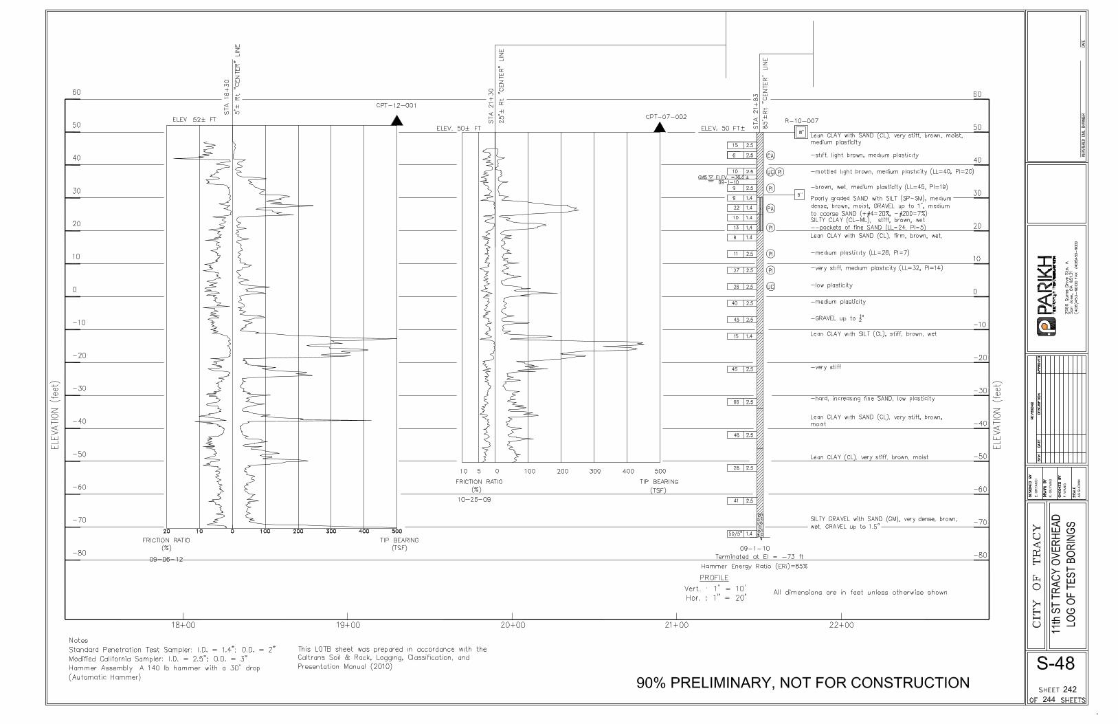
The test borings were advanced with a truck-mounted drill rig. Borings R-10-005 and R-10-007
were advanced by using hollow stem augers above groundwater then switched to rotary wash
drilling method when groundwater was encountered. Borings R-10-004 and R-10-009 were
advanced primarily by rotary wash drilling method.
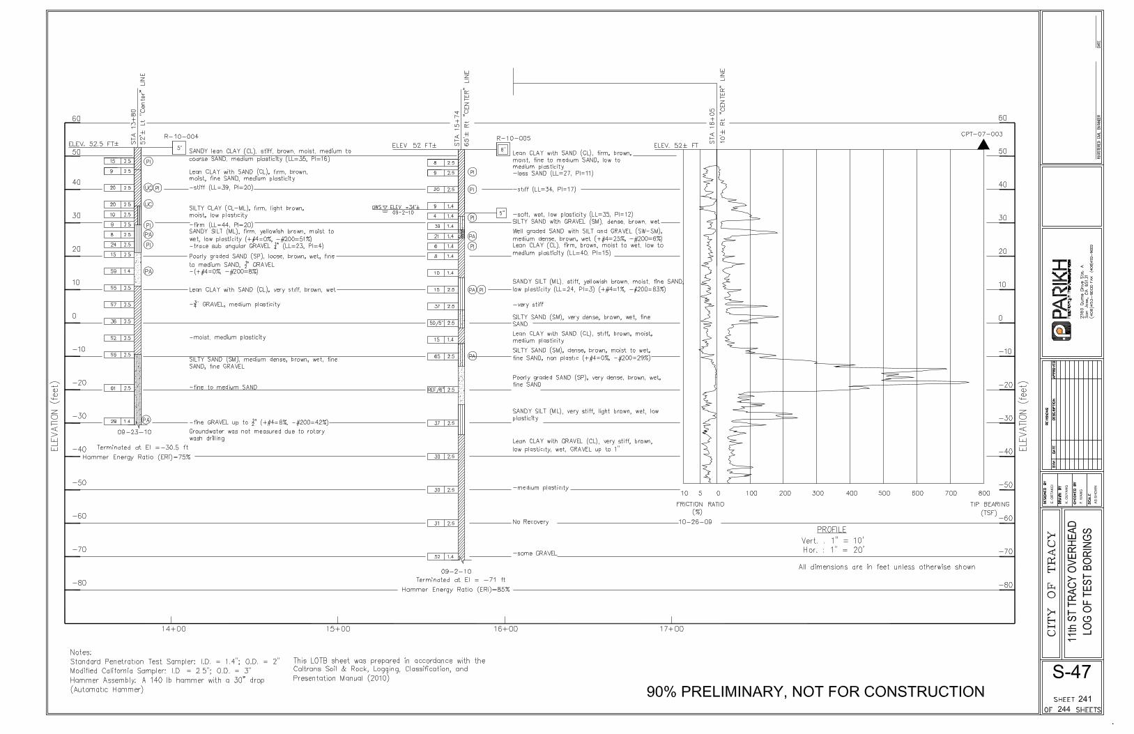
Selected samples were obtained from 2.5-inch I.D. Modified California (MC) sampler and
1.4-inch I.D. Standard Penetration Test (SPT) sampler at various depths. The samplers were
driven into subsurface soils under the impact of a 140-pound hammer having a free fall of 30
inches. The blow counts are presented on the Log of Test Boring (LOTB) in Appendix II. When
correlating standard penetration data, the blow counts for the MC Sampler may be converted to
equivalent SPT blow counts by multiplying a conversion factor of 0.65. The samples were sealed
and transported to our laboratory for further evaluation and testing. The field investigation was
conducted under the supervision of our field engineer who logged the test borings and prepared the
samples for subsequent laboratory testing and evaluation.
Drake Haglan & Associates
Job No. 2005-151-PSE (11th
Street OH)
March 25th
, 2014
Page 3
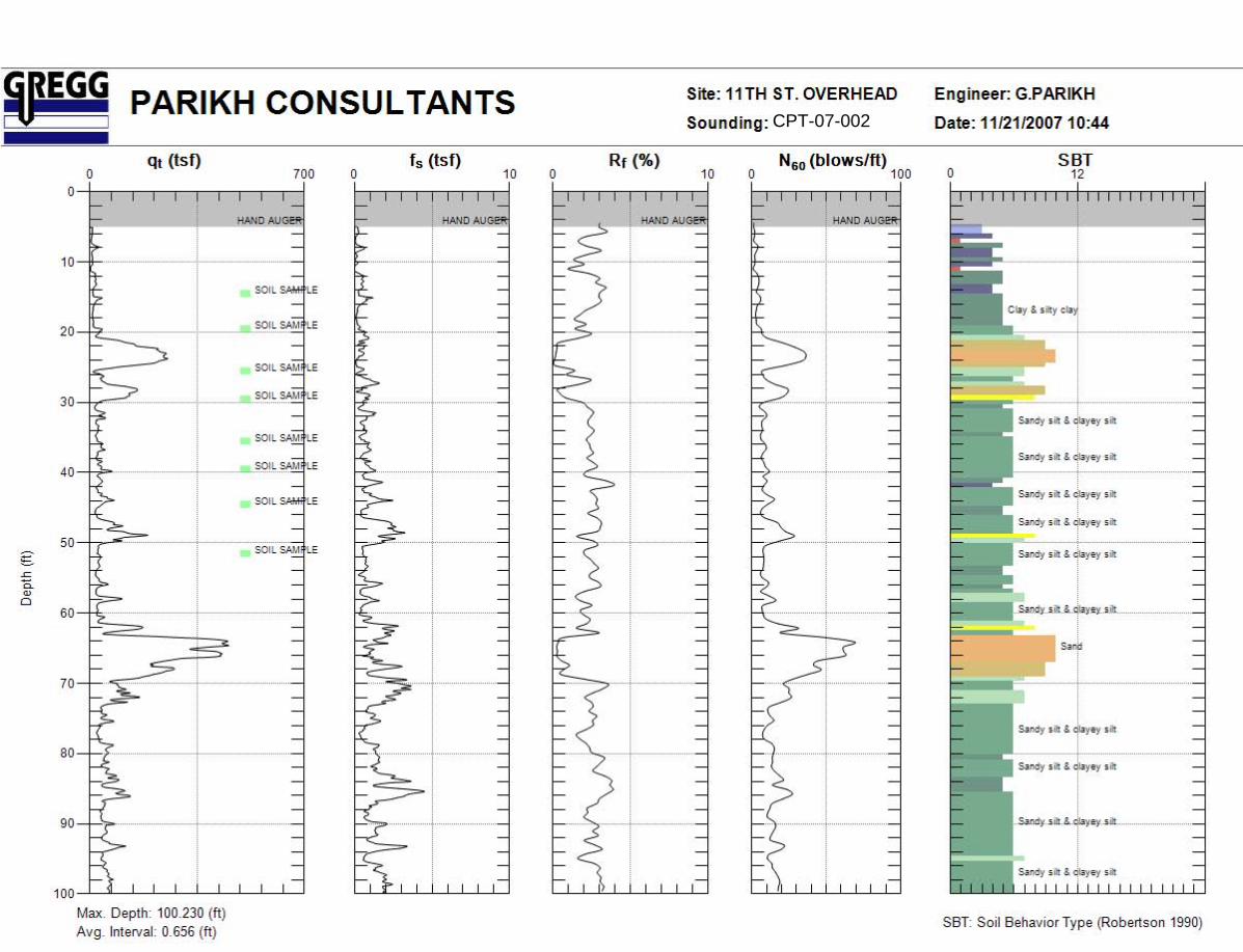
The CPTs were performed by Gregg Drilling & In Situ, Inc. of Martinez, CA. The CPTs were
conducted by using a 20-Ton capacity cone with a 60-degree cone attached to a 1.7-inch diameter
(tip area of 55 cm2) rod. The soil resistance exerted to the tip and side of the cone were recorded
and correlated to “Soil Behavior Type”, classification and strength characteristics.
The bore logs presented in Appendix II were prepared from the field logs which were edited after
visual re-examination of the soil samples in the laboratory and results of classification tests on
selected soil samples as indicated on the logs. The abrupt stratum changes shown on these logs
may be gradual and relatively minor changes in soil types within a stratum may not be noted on the
logs due to field limitations.
5.0 LABORATORY TESTING PROGRAM
Laboratory tests were performed on selected samples in the laboratory to evaluate the physical and
engineering properties of the subsoils. The tests performed for the study include the following:
Laboratory determination of Moisture (California Test Method 226), Unit Weight (California Test
Method 212), Atterberg Limits (California Test Method 204), Grain Size Analysis (California Test
Method 202), Unconfined Compression Test (California Test Method 221), Resistivity and pH
Test (California Test Method 643), Sulfate Content (California Test Method 417), Chloride
Content (California Test Method 422) and Consolidation Test (California Test Method 219). The
laboratory test results are attached in Appendix IV.
6.0 SITE GEOLOGY AND SUBSURFACE CONDITIONS
Site Geology 6.1
General geologic features pertaining to the site were evaluated by reference to the Geologic
Map of the San Francisco – San Jose Quadrangle, by D. L. Wagner, E. J. Bortugno and R. D.
McJunkin (CDMG, Map No. 5A, 1990). Based on the publication, the project site subsoils
generally consist of alluvium fan deposits (Qf).
Subsurface Conditions 6.2
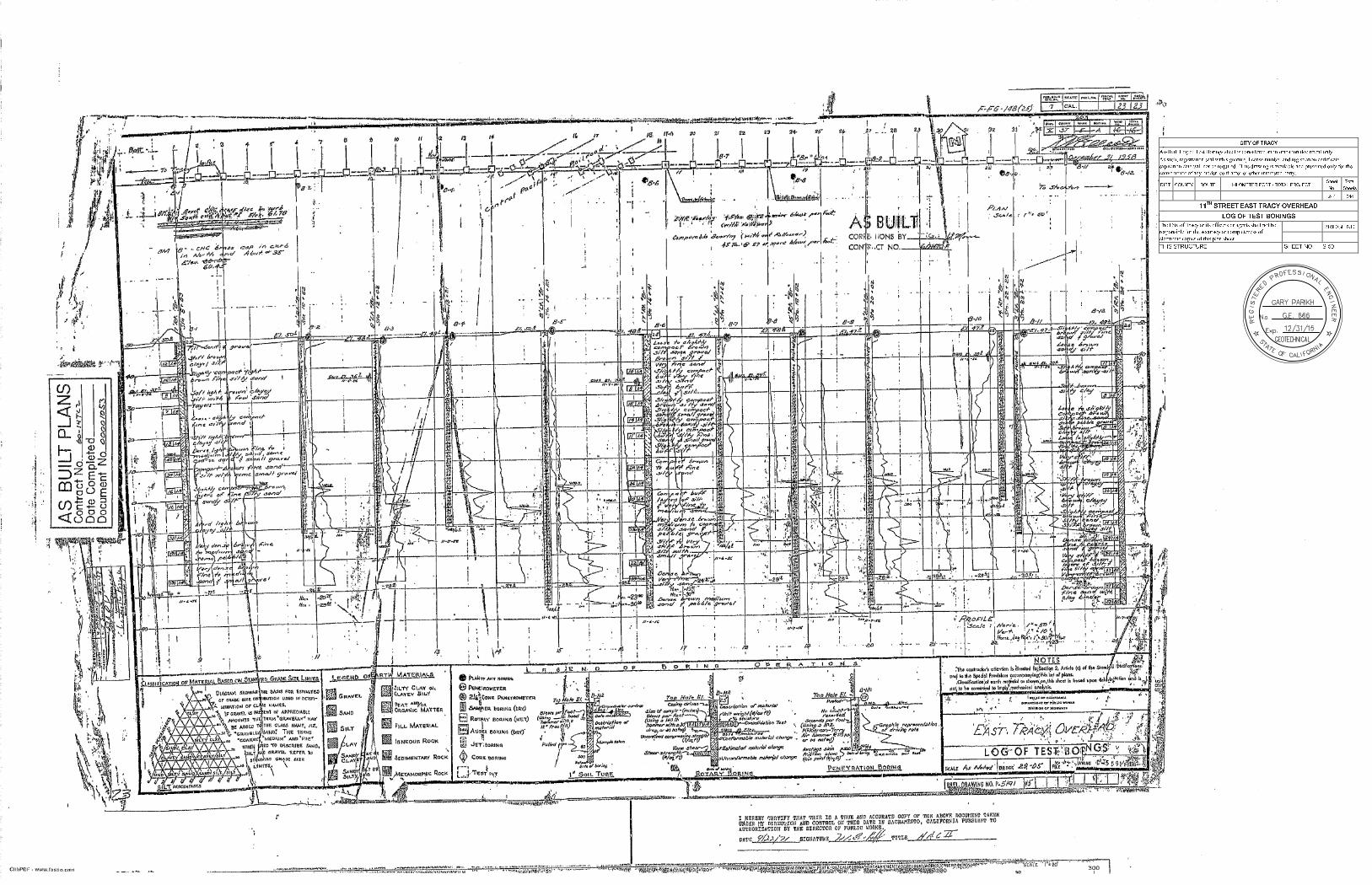
We have reviewed the as-built LOTB (Caltrans 1963) of the existing East Tracy Overhead (Br.
No. 29-0005). Additional four borings and six CPTs were conducted under our scope of work.
The subsoils generally consist of interbedded medium stiff to stiff clayey silt and loose to
slightly compact silty sand. Two major sand layers were encountered at about 20- to 25-foot
and 60- to 75-foot depths, and the sand layers are more prominent on the west side of the
proposed overhead structure. Other sporadic, relatively thin sand lenses were encountered at
various depths. The CPTs also show predominantly fine grained materials at the site with
interbedded layers of sands with varying thicknesses of 2 to 10 feet. Boring R-10-007
Drake Haglan & Associates
Job No. 2005-151-PSE (11th
Street OH)
March 25th
, 2014
Page 4
encountered very dense silty gravel at the bottom of the boring at about Elev. -70 feet.
CPT-12-001 was also terminated at the same depth due to practical refusal.
Groundwater 6.3
Based on the as-built boring data, groundwater was encountered at Elev. 35 to 37 feet
(approximately 13 to 15 feet below the grade) during field exploration in 1956. Per Pore
Pressure Dissipation Test results conducted in November 2007, groundwater was measured
between 9.3 feet and 12.5 feet below existing grade. According to the explorations conducted
during the PS&E design phase, groundwater was encountered at about 18 and 14 feet below
existing grade in Borings R-10-005 and R-10-007, respectively, and groundwater was
measured at about 12.4 feet and 15.8 feet below existing grade from the Pore Pressure
Dissipation Test results conducted in September 2012
The groundwater encountered/measured in the boring and CPT data are relatively consistent.
However, please note that groundwater may vary with the passage of time due to seasonal
groundwater fluctuation, surface and subsurface flows, ground surface run-off, and other
factors that may not be present at the time of investigation. We have assumed groundwater at
10 feet below existing grade for design purpose.
7.0 SCOUR EVALUATION
The subject was considered and was determined to be not applicable for the project.
8.0 CORROSION EVALUATION
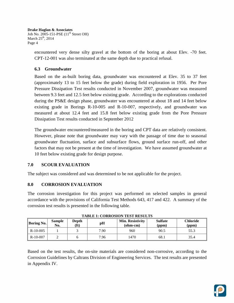
The corrosion investigation for this project was performed on selected samples in general
accordance with the provisions of California Test Methods 643, 417 and 422. A summary of the
corrosion test results is presented in the following table.
TABLE 1: CORROSION TEST RESULTS
Boring No. Sample
No.
Depth
(ft) pH
Min. Resistivity
(ohm-cm)
Sulfate
(ppm)
Chloride
(ppm)
R-10-005 1 3 7.90 960 90.5 55.3
R-10-007 2 6 7.96 1470 68.1 35.4
Based on the test results, the on-site materials are considered non-corrosive, according to the
Corrosion Guidelines by Caltrans Division of Engineering Services. The test results are presented
in Appendix IV.
Drake Haglan & Associates
Job No. 2005-151-PSE (11th
Street OH)
March 25th
, 2014
Page 5
9.0 SEISMIC RECOMMENDATIONS
Seismic Sources 9.1
The project site is located in a seismically active part of northern California. Many faults
existing in northern California are capable of producing earthquakes and may cause strong
ground shaking at the site.
Maximum moment magnitudes (MMax) of some of the closest faults in the area are based on
2007 Caltrans Deterministic PGA Map and ARS Online Report. These maximum moment
magnitudes represent the largest earthquake a fault is capable of generating and is related to the
seismic moment. The earthquake data of the active faults in the project vicinity are
summarized below.
TABLE 2 – EARTHQUAKE DATA
Fault
(Fault ID) Maximum Magnitude, MMax Fault Type
Site-to-Fault
Distance
Great Valley fault 7
(25) 6.7 Reverse Approx. 4.75 miles
Greenville fault zone
(350, 352) 6.6
Right-Lateral-Strike-Slip
(RLSS) Approx. 14 miles
Seismic Hazards 9.2
Potential seismic hazards may arise from three sources: surface fault rupture, ground shaking
and liquefaction. Since no active faults pass through the site, the potential for fault rupture is
relatively low. As shown on the Fault Map (Plate V-1), the closest active fault is located at
about 4.75 miles from the site. Based on available geological and seismic data, the possibility
of the site to experience strong ground shaking may be considered medium to high.
Liquefaction Potential 9.3
Potential seismic hazards may arise from three sources: surface fault rupture, ground shaking
and liquefaction. Since no active faults pass through the site, the potential for fault rupture is
relatively low. As shown on the Fault Map (Plate V-1), the closest active fault is located at
about 4.75 miles from the site. Based on available geological and seismic data, the possibility
of the site to experience strong ground shaking may be considered medium to high.
For liquefaction analyses, we have adopted Peak Ground Acceleration (PGA) of 0.465g for the
permanent structure and 0.227g for the temporary detour structure (see Section 9.4 for more
discussions). The liquefaction potential was evaluated in accordance with the methods
proposed by Youd, et al. (2001), primarily using the boring data that were performed in August
and September 2010. As indicated by recent advances in soil liquefaction engineering (Bray,
Drake Haglan & Associates
Job No. 2005-151-PSE (11th
Street OH)
March 25th
, 2014
Page 6
2006), for soils with sufficient fines content so as to separate the coarser particles and control
behavior, liquefaction appears to occur in soils where these fines are either non-plastic or are
low plasticity silts and/or silty clays (PI<12%, and LL<37%), and with high water content
relative to their liquid limit (w> 0.85LL).
In general, liquefaction hazards are most severe in the upper 50 feet of the surface as mentioned in
Special Publication 117A (CGS, 2008). In our opinion, the impact due to the potential liquefiable
soils below 50 feet is considered insignificant, especially when the layer is relatively thin and
discontinuous. Therefore, liquefaction potential for soils below 50 feet was not evaluated.
Based on the boring data, some of the fine-grained materials encountered have relatively low
plasticity and high natural moisture contents. According to the criteria suggested by Bray (2006),
these materials are expected to have “sand-like” behavior. Therefore, the liquefaction potential at
the project site was evaluated primarily based on the boring data. Based on the analysis results,
these soils may experience temporary loss of strength due to 100% development of pore pressure
with the higher level of design earthquake for the permanent structure (PGA of 0.465g). The soil
layers that may be subject to liquefaction are summarized in the following table. Based on the
analysis results, we have assumed a layer of liquefiable soils between Elev. 12.5 and 25 feet when
evaluating pile capacity and embankment stability.
TABLE 3: POTENTIAL LIQUEFIABLE SOILS (PERMANENT DESIGN)
Boring No. Soil Layer
(Depth, ft) Soil Type N1,60
Moisture
Content
(w, %)
Atterberg Limits (%) w/LL
LL PI
R-10-004 23.0 to 31.5 ML 5.5 to 16.9 21.1 to 22.9 23 4 >0.9
R-10-005 18.0 to 20.0 ML 5.2 33.0 35 12 >0.9
38.5 to 42.5 ML 11.6 25.6 24 3 ~1.0
R-10-007 25.0 to 38.5 ML 9.1 to 18.3 20.8 to 31.1 24 to 28 5 to 7 ~1.0
R-10-009 33.0 to 37.5 ML 16.6 24.7 24 to 28(*)
5 to 7(*)
~1.0
* Note: The Atterberg limits were referred to the test results from R-10-007 at the similar depths.
For the temporary detour structure, the factor of safety (FS) against liquefaction is generally
greater than 1.0. The samples with FS less than 1.0 appear to be sporadic and not continuous.
Therefore, the overall impact due to liquefaction is considered negligible, especially when the
service life of the temporary structure is anticipated to be about 24 months. Liquefaction was not
considered for foundation design for the temporary structure.
Seismic Design Criteria 9.4
The recommended acceleration response spectrum (ARS) curves were developed during 35%
design phase based on the 2007 Caltrans Deterministic PGA Map and the Caltrans ARS Online
Drake Haglan & Associates
Job No. 2005-151-PSE (11th
Street OH)
March 25th
, 2014
Page 7
(Ver. 1.0.4). The ARS curves were presented in our Preliminary Foundation Report (dated
April 28th
, 2011), and the type of structure and foundation was selected in June 2011.
The development of the design ARS curve is based on several input parameters, including site
location (longitude/latitude), average shear wave velocity for the top 30 m/100 feet (VS30m),
and other site parameters, such as fault characteristics, site-to-fault distances. The design
methods incorporate both deterministic and probabilistic seismic hazards to produce the
Design Response Spectrum. According to the design manual, we have also compared with the
probabilistic response spectrum from 2008 USGS Deaggregation Hazard (beta) web site for
the 5% in 50 years probability of exceedance (or 975 year return period).
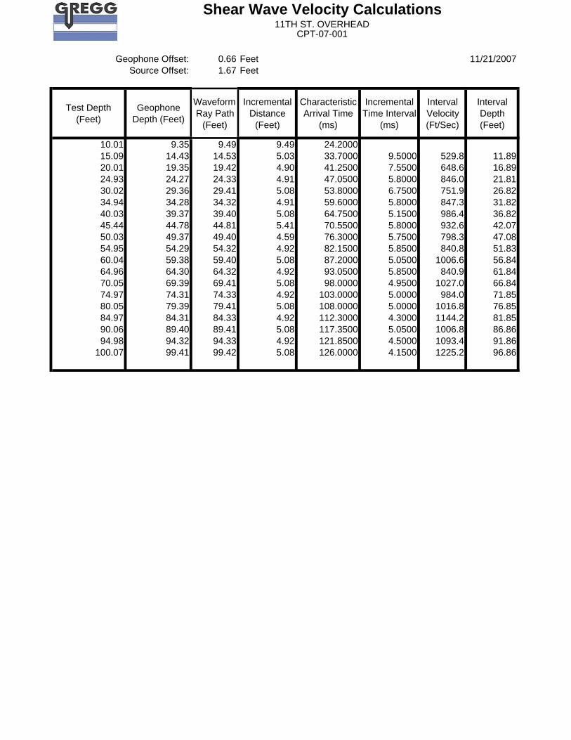
The average shear wave velocity (Vs) for the top 30m (100 feet) at the site was estimated by
using established correlations and the procedure provided in the Design Manual (Ver. 1.0,
August 2009). Shear wave velocity was also calculated based on the measurement from the
Seismic Cone Penetrometer Testing (SCPTu) where Vs was measured in 5-foot interval
through 100 feet.
As discussed in the previous section, some of the submerged, low-plastic soils encountered in
the borings may be subject to liquefaction during strong seismic event. When estimating the
VS30m, we have modeled the potential liquefiable soils as soft clay with residual shear strengths
per Kramer and Wang (2007) as cited in Caltrans guideline. For developing the ARS curve, we
have considered both profiles: (1) liquefaction case; and (2) non-liquefaction case. Based on
our calculation, we have estimated VS30m of 185 m/s and 230 m/s for liquefaction case and
non-liquefaction case, respectively. According to the analysis results, the recommended ARS
curve for the permanent overhead structure is governed by the data from 2008 USGS
Deaggregation Hazard (beta) with VS30m of 185 m/s.
For the temporary detour structure, the service life of the structure will only be during
construction and is expected to be about 24 months. Therefore, the seismic design was
determined based on 10% in 10 years probability of exceedance per Caltrans
Memo-To-Designer 20-12 (MTD, February 2003). We have utilized the USGS Deaggregation
Hazard (beta) website to generate the design ARS curve. The “10% in 10 years probability of
exceedance” is not available from the website. Consequently, we have assumed 50% in 75
years probability of exceedance with a mean return period of 108 years, which is on the similar
order of 10% in 10 years probability of exceedance (return period of 95 years), for generating
the design spectrum. We have conservatively adopted the same average VS30m of 185 m/s as
the permanent structure.
Drake Haglan & Associates
Job No. 2005-151-PSE (11th
Street OH)
March 25th
, 2014
Page 8
The site location and the relevant parameters are summarized as follows, and the
recommended design curves are presented in Appendix V of this report. Both curves were
adjusted with Near Fault Effect and Basin Effect.
1. Site Location: 37.7397ºN/121.4100ºW
2. Average VS30m = 185 m/s
3. Depth to rock with a shear wave velocity of 2.5 km/sec (Z2.5) = 3.05 km
4. The recommended ARS curves are governed by 2008 USGS Deaggregation Hazard (beta).
5. Anticipated PGA: 0.465g (11th Street East Tracy OH); 0.227g (Temporary Detour
Structure)
10.0 AS-BUILT FOUNDATION DATA
The existing bridge is a 34-span structure and was originally built in 1936, and the structure is
founded on timber piles. There is no as-built information available for the original structure, and
the foundation detail is unknown. The structure was widened in 1960, and the associated as-built
plans (Widening East Tracy Overhead, Br. No. 29-05, Caltrans, 1958) were provided by the
designer.
According to the as-built plans, the widened portion of the structure is supported on H piles
(10BP42) with design load of 45 tons. The specified pile tip elevation is at Elev. -10 feet and the
estimated tip elevation is at Elev. -30 feet. The pile driving records shown on the as-built LOTB
indicate that the piles were driven to an average tip elevation between Elev. -27 to -30 feet.
11.0 FOUNDATION RECOMMENDATIONS
General 11.1
This report was prepared specifically for the proposed project as described earlier. Normal
procedures were assumed for construction of the bridge structure throughout our analysis and
represent one of the bases of recommendations presented herein. Our design criteria have been
based upon the materials encountered at the site. Therefore, we should be notified in the event
that these conditions are changed, so as to modify or amend our recommendations. In addition,
bridge plans should be reviewed by our office prior to finalizing the plans to see that the intent
of our recommendations is included in the plans.
Foundation 11.2
Based on the subsurface condition, the subsoils at the project site consist of predominantly
fine-grained materials with some sand layers, and groundwater level appears relatively
shallow. Liquefiable soils have been identified within the project limit, which was considered
for foundation design that is associated with seismic loading. Per discussion with the designer,
Drake Haglan & Associates
Job No. 2005-151-PSE (11th
Street OH)
March 25th
, 2014
Page 9
96-inch diameter CIDH piles will be used for foundation support for the permanent structure,
and 42-inch diameter CIDH piles will be used for the temporary detour structure.
Caltrans typically uses Load and Resistant Factor Design (LRFD) for the bents and Working
Stress Design (WSD) for the abutments. However, for this project, the abutments were
specifically designed with pile columns instead of a tall abutment wall. The primary purpose is
to minimize the lateral earth pressure acting on the abutments so that the construction cost can
be reduced. Per our discussion with the designer, the abutments are expected to behave more
like bents, and pipe keys will be used to connect the substructure to the superstructure.
Consequently, the abutments will be designed per LRFD as bent foundations. Based on
information provided by the designer, the cut-off elevations of the CIDH piles at the abutments
are at Elev. 50 feet for both the permanent overhead and the detour structures.
The strength parameters used for foundation design are presented in Appendix V. We have
reviewed the available boring and CPT data and primarily focused on CPT-12-001,
CPT-07-002 and R-10-007 to develop the strength parameters for designing the proposed
CIDH piles. The pile capacity of the CIDH piles was estimated based on the procedures shown
in AASHTO LRFD Bridge Design Specification, i.e. Reese and O’Neil (1999). The pile
capacity of the CIDH pile will be derived primarily from frictional resistance along the pile
shafts, and end bearing capacity was not included when estimating the pile capacity. We have
utilized computer program “Shaft” (ENSOFT, v6.0) for calculation purpose.
For the proposed pile type, the recommended minimum pile spacing is three times the pile
diameter (3D, center-to-center) to minimize the group effect for vertical pile capacities. When
estimating the vertical pile capacity for extreme limit state, the contribution within the
potential liquefiable soil layers was neglected, and down drag load was considered.
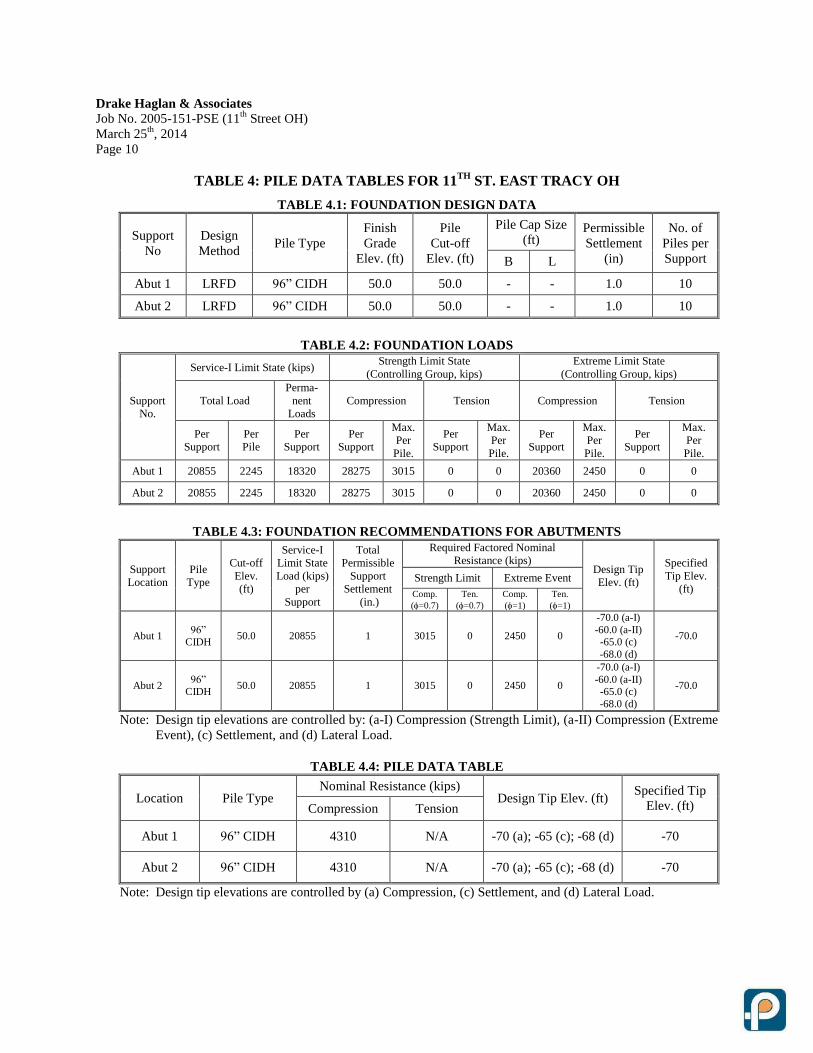
The foundation design information provided by the designer and foundation recommendations
are presented in the following tables. Based on the load demand and subsoil information, the
recommended specified pile tip elevations are also shown in the Pile Data Table per Caltrans
MTD 3-1.
Drake Haglan & Associates
Job No. 2005-151-PSE (11th
Street OH)
March 25th
, 2014
Page 10
TABLE 4: PILE DATA TABLES FOR 11TH
ST. EAST TRACY OH
TABLE 4.1: FOUNDATION DESIGN DATA
Support
No
Design
Method Pile Type
Finish
Grade
Elev. (ft)
Pile
Cut-off
Elev. (ft)
Pile Cap Size
(ft) Permissible
Settlement
(in)
No. of
Piles per
Support B L
Abut 1 LRFD 96” CIDH 50.0 50.0 - - 1.0 10
Abut 2 LRFD 96” CIDH 50.0 50.0 - - 1.0 10
TABLE 4.2: FOUNDATION LOADS
Support
No.
Service-I Limit State (kips) Strength Limit State
(Controlling Group, kips)
Extreme Limit State
(Controlling Group, kips)
Total Load
Perma-
nent
Loads
Compression Tension Compression Tension
Per
Support
Per
Pile
Per
Support
Per
Support
Max.
Per
Pile.
Per
Support
Max.
Per
Pile.
Per
Support
Max.
Per
Pile.
Per
Support
Max.
Per
Pile.
Abut 1 20855 2245 18320 28275 3015 0 0 20360 2450 0 0
Abut 2 20855 2245 18320 28275 3015 0 0 20360 2450 0 0
TABLE 4.3: FOUNDATION RECOMMENDATIONS FOR ABUTMENTS
Support
Location
Pile
Type
Cut-off
Elev.
(ft)
Service-I
Limit State
Load (kips)
per
Support
Total
Permissible
Support
Settlement
(in.)
Required Factored Nominal
Resistance (kips) Design Tip
Elev. (ft)
Specified
Tip Elev.
(ft) Strength Limit Extreme Event
Comp.
(=0.7)
Ten.
(=0.7)
Comp.
(=1)
Ten.
(=1)
Abut 1 96”
CIDH 50.0 20855 1 3015 0 2450 0
-70.0 (a-I)
-60.0 (a-II) -65.0 (c)
-68.0 (d)
-70.0
Abut 2 96”
CIDH 50.0 20855 1 3015 0 2450 0
-70.0 (a-I)
-60.0 (a-II) -65.0 (c)
-68.0 (d)
-70.0
Note: Design tip elevations are controlled by: (a-I) Compression (Strength Limit), (a-II) Compression (Extreme
Event), (c) Settlement, and (d) Lateral Load.
TABLE 4.4: PILE DATA TABLE
Location Pile Type Nominal Resistance (kips)
Design Tip Elev. (ft) Specified Tip
Elev. (ft) Compression Tension
Abut 1 96” CIDH 4310 N/A -70 (a); -65 (c); -68 (d) -70
Abut 2 96” CIDH 4310 N/A -70 (a); -65 (c); -68 (d) -70
Note: Design tip elevations are controlled by (a) Compression, (c) Settlement, and (d) Lateral Load.
Drake Haglan & Associates
Job No. 2005-151-PSE (11th
Street OH)
March 25th
, 2014
Page 11
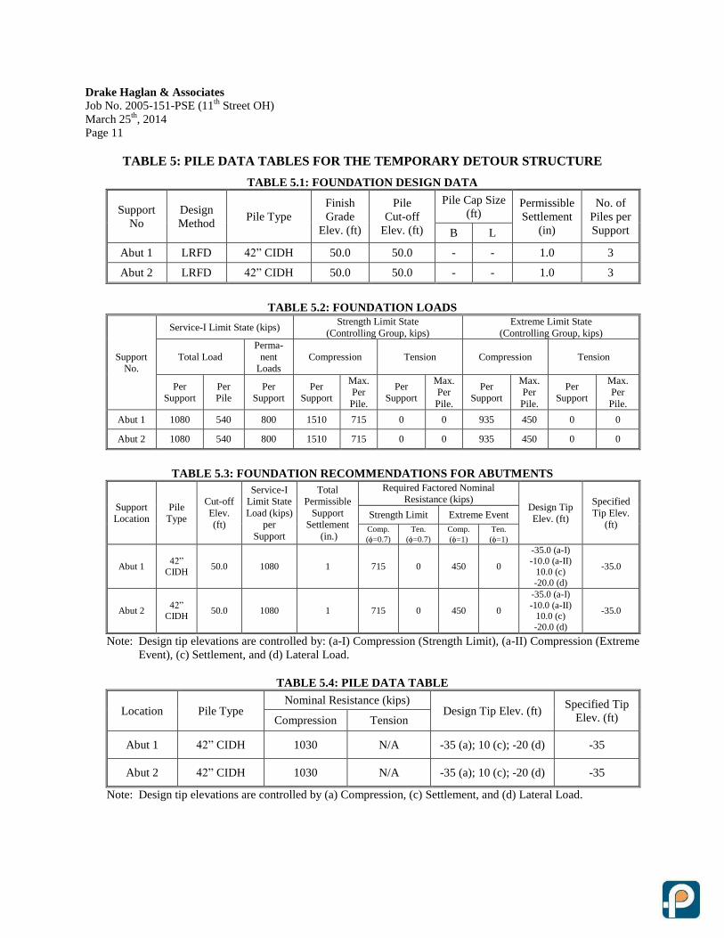
TABLE 5: PILE DATA TABLES FOR THE TEMPORARY DETOUR STRUCTURE
TABLE 5.1: FOUNDATION DESIGN DATA
Support
No
Design
Method Pile Type
Finish
Grade
Elev. (ft)
Pile
Cut-off
Elev. (ft)
Pile Cap Size
(ft) Permissible
Settlement
(in)
No. of
Piles per
Support B L
Abut 1 LRFD 42” CIDH 50.0 50.0 - - 1.0 3
Abut 2 LRFD 42” CIDH 50.0 50.0 - - 1.0 3
TABLE 5.2: FOUNDATION LOADS
Support
No.
Service-I Limit State (kips) Strength Limit State
(Controlling Group, kips)
Extreme Limit State
(Controlling Group, kips)
Total Load
Perma-
nent
Loads
Compression Tension Compression Tension
Per
Support
Per
Pile
Per
Support
Per
Support
Max.
Per
Pile.
Per
Support
Max.
Per
Pile.
Per
Support
Max.
Per
Pile.
Per
Support
Max.
Per
Pile.
Abut 1 1080 540 800 1510 715 0 0 935 450 0 0
Abut 2 1080 540 800 1510 715 0 0 935 450 0 0
TABLE 5.3: FOUNDATION RECOMMENDATIONS FOR ABUTMENTS
Support
Location
Pile
Type
Cut-off
Elev.
(ft)
Service-I
Limit State
Load (kips)
per
Support
Total
Permissible
Support
Settlement
(in.)
Required Factored Nominal
Resistance (kips) Design Tip
Elev. (ft)
Specified
Tip Elev.
(ft) Strength Limit Extreme Event
Comp.
(=0.7)
Ten.
(=0.7)
Comp.
(=1)
Ten.
(=1)
Abut 1 42”
CIDH 50.0 1080 1 715 0 450 0
-35.0 (a-I)
-10.0 (a-II) 10.0 (c)
-20.0 (d)
-35.0
Abut 2 42”
CIDH 50.0 1080 1 715 0 450 0
-35.0 (a-I)
-10.0 (a-II) 10.0 (c)
-20.0 (d)
-35.0
Note: Design tip elevations are controlled by: (a-I) Compression (Strength Limit), (a-II) Compression (Extreme
Event), (c) Settlement, and (d) Lateral Load.
TABLE 5.4: PILE DATA TABLE
Location Pile Type Nominal Resistance (kips)
Design Tip Elev. (ft) Specified Tip
Elev. (ft) Compression Tension
Abut 1 42” CIDH 1030 N/A -35 (a); 10 (c); -20 (d) -35
Abut 2 42” CIDH 1030 N/A -35 (a); 10 (c); -20 (d) -35
Note: Design tip elevations are controlled by (a) Compression, (c) Settlement, and (d) Lateral Load.
Drake Haglan & Associates
Job No. 2005-151-PSE (11th
Street OH)
March 25th
, 2014
Page 12
The lateral pile analyses were performed by the structure engineer and the design tip elevations
were provided to us. The pile group settlement was evaluated per AASHTO LRFD Bridge
Design Specifications. Based on the subsurface condition and the recommended waiting
period of the new embankment, it is our opinion that pile group settlement should not be a
design concern. The analysis results indicate that the induced settlement due to the pile group
is within the tolerable limits, and the pile group settlement does not govern the pile design.
According to our analysis, the estimated pile length of the 96-inch diameter CIDH piles will be
120 feet, and the 42-inch diameter CIDH will be 85 feet. For such long piles, temporary casing
is recommended to minimize the construction difficulty due to potential raveling or caving. In
our opinion, the use of casing oscillator/rotator techniques for CIDH construction may be
considered to facilitate the pile construction. This method has been successfully adopted in
various projects throughout California. More discussions regarding construction
considerations of the proposed CIDH piles are presented in Section 14.2.
Lateral Pile Capacity 11.3
The lateral pile analyses were performed by the structure engineer based on the geotechnical
parameters recommended in this section. It is our understanding that the lateral design does
not govern the length of the piles.
Potentially liquefiable soils were identified within the project limit, which may lose their shear
strength during a strong seismic event. Based on the slope stability analysis (see Section
11.5.2), permanent ground deformation of the embankment and MSE walls, i.e. lateral
spreading, is expected due to the presence of the liquefiable soils.
Caltrans published “Guidelines on Foundation Loading and Deformation Due to Liquefaction
Induced Lateral Spreading” in February 2011 and was updated in January 2012. The
publication provides a step-by-step procedure to calculate lateral spreading induced foundation
loads under seismic loading. The guideline is limited in its application to traditional seated
abutments and bents. However, the proposed overhead structure is highly skewed, and the
abutments are designed as free standing piers. Thus, our lateral pile design is in general
accordance of this Caltrans guideline except where the guideline is not applicable to the
specifics of the project design.
Based on the subsurface condition, lateral load analyses were performed for the proposed
CIDH piles at Abutment 1 and Abutment 2 by using the LPILE program (ENSOFT, v6.0). The
recommended geotechnical parameters are presented in the following tables. The
recommended strength parameters have been revised from the values presented in our
Preliminary Foundation Report (PFR), dated April 2011, after further reviewing the additional
Drake Haglan & Associates
Job No. 2005-151-PSE (11th
Street OH)
March 25th
, 2014
Page 13
CPTs conducted in 2012. We have primarily focused on CPT-12-001, CPT-07-002 and
R-10-007 to develop the strength parameters for the pile design. The strength parameters
provided in the previous PFR appear to be more conservative.
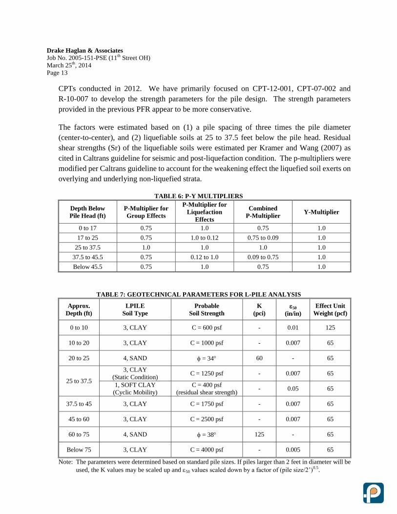
The factors were estimated based on (1) a pile spacing of three times the pile diameter
(center-to-center), and (2) liquefiable soils at 25 to 37.5 feet below the pile head. Residual
shear strengths (Sr) of the liquefiable soils were estimated per Kramer and Wang (2007) as
cited in Caltrans guideline for seismic and post-liquefaction condition. The p-multipliers were
modified per Caltrans guideline to account for the weakening effect the liquefied soil exerts on
overlying and underlying non-liquefied strata.
TABLE 6: P-Y MULTIPLIERS
Depth Below
Pile Head (ft)
P-Multiplier for
Group Effects
P-Multiplier for
Liquefaction
Effects
Combined
P-Multiplier Y-Multiplier
0 to 17 0.75 1.0 0.75 1.0
17 to 25 0.75 1.0 to 0.12 0.75 to 0.09 1.0
25 to 37.5 1.0 1.0 1.0 1.0
37.5 to 45.5 0.75 0.12 to 1.0 0.09 to 0.75 1.0
Below 45.5 0.75 1.0 0.75 1.0
TABLE 7: GEOTECHNICAL PARAMETERS FOR L-PILE ANALYSIS
Approx.
Depth (ft)
LPILE
Soil Type
Probable
Soil Strength
K
(pci) 50
(in/in)
Effect Unit
Weight (pcf)
0 to 10 3, CLAY C = 600 psf - 0.01 125
10 to 20 3, CLAY C = 1000 psf - 0.007 65
20 to 25 4, SAND = 34 60 - 65
25 to 37.5
3, CLAY
(Static Condition) C = 1250 psf - 0.007 65
1, SOFT CLAY
(Cyclic Mobility)
C = 400 psf
(residual shear strength) - 0.05 65
37.5 to 45 3, CLAY C = 1750 psf - 0.007 65
45 to 60 3, CLAY C = 2500 psf - 0.007 65
60 to 75 4, SAND = 38 125 - 65
Below 75 3, CLAY C = 4000 psf - 0.005 65
Note: The parameters were determined based on standard pile sizes. If piles larger than 2 feet in diameter will be
used, the K values may be scaled up and 50 values scaled down by a factor of (pile size/2’)0.5
.
Drake Haglan & Associates
Job No. 2005-151-PSE (11th
Street OH)
March 25th
, 2014
Page 14
Since the abutments are supported on 96-inch diameter CIDH piles with column extension,
single pile with tributary area approach (instead of the super pile approach) was considered for
the analysis as it is deemed more appropriate for the proposed abutment design. Per our
discussion with the designer, the abutments will be connected to the superstructure by pipe
keys.
Based on the procedure outlined in Caltrans lateral spreading guideline (Section 3.5),
displacement compatibility plots were prepared for both longitudinal and transverse directions
of the structure. The crustal displacement was estimated per Bray and Travasarou model
(2007) as cited in the Caltrans guideline, which is a function of yield coefficient (ky), PGA and
fault magnitude. The yield coefficients were obtained from slope stability analysis based on a
range of possible foundation restoring forces.
It is our understanding that this connection will equally distribute the inertial loads to the CIDH
piles. When estimating the foundation resistive forces, we used 50% of the inertial loads
provided by the structural engineer in combination with 100% of the kinematic loads as
recommended in the Caltrans guideline for our LPILE analysis, with various crustal
displacements. Passive soil resistance behind the abutments was considered for the analysis in
the longitudinal direction.
According to our evaluation, the estimated ground displacement under design seismic event is
approximately 2.6 inches along longitudinal direction and 2.5 inches along transverse
direction. To account for the uncertainties due to the highly-skewed design of the structure, a
ground displacement of 3.5 inches is recommended for design in both directions.
The results of the lateral spreading analyses are shown in the Appendix V of the report. It is
recommended that the structural engineer verify the displacement compatibility plots for more
accurate results.
Embankments and MSE Walls 11.4
MSE walls are planned to support the approach embankment and to accommodate
right-of-way and geometric constraints. Such wall system is generally considered more
economical particularly in fill situations, and it is popular for its high-load capacity, speedy
installation, durability, relatively low maintenance, and cost efficiency.
Based on the information provided by the designer, the embankments will be supported by
two-tiered MSE walls. We have conducted engineering analyses to provide recommendations
for bearing capacity, settlement and waiting period, and slope stability for global aspects of the
Drake Haglan & Associates
Job No. 2005-151-PSE (11th
Street OH)
March 25th
, 2014
Page 15
embankment and walls. The details of internal wall design, such as the length of the
reinforcement, will be performed by the designer.
11.4.1 Bearing Capacity of MSE Walls
MSE walls are more flexible and can accommodate much greater settlement than typical
cantilever concrete retaining walls. Therefore, for cohesive soils, bearing capacity will be
based on the effective strength parameters. The adequacy of the bearing capacity of the
foundation soils immediately upon completion of construction was evaluated based on the
overall stability of the MSE walls.
Based on the boring data, the subgrade materials consist of primarily lean clay. Drained
strength parameters, ϕ’ of 28 and c’ of 200 psf, were assumed for design purpose. Since
the base width of the wall varies and can be up to 30 feet, we have conservatively assumed
high groundwater level below the bottom of the MSE walls and adopted a uniform buoyant
unit weight of 65 pcf for design.
The bearing capacity is mainly a function of the base width. We have calculated the
nominal (ultimate) bearing capacities per equation 4‐ 22 of “Design and Construction of
MSE Walls and RSS” (FHWA‐NHI‐ 10‐ 024, November 2009) with various design base
widths (B). The results are presented in Appendix V.
As discussed, the bearing capacity is generally not a governing factor since the ground is
allowed to settlement under drained condition. The global slope stability immediately after
construction (short-term undrained condition) can be more critical. Detail analysis and
discussions are presented in Section 11.5.3 “Embankment Stability”.
11.4.2 Settlement Under Embankments and MSE Walls
Consolidation settlement is anticipated due to the proposed approach embankment and the
MSE walls. Consolidation tests were conducted on selected samples obtained from the
borings. We have reviewed and adopted correlations from various references with revision
to the site-specific laboratory test results for estimating the indexes for settlement
calculation. The estimation of pre-consolidation pressure is based Su/p per Skempton
(1957) and NAVFAC D.M. 7.1. The modified compression index (Cc/(1+e0)) and the
recompression index (Cr/(1+e0)) were estimated based on the laboratory test results and
were also compared to the correlation with natural moisture content based on Lambe and
Whitman (1969).

Drake Haglan & Associates
Job No. 2005-151-PSE (11th
Street OH)
March 25th
, 2014
Page 16
Based on the subsurface condition, the site is underlain by predominantly fine-grained
materials. According to the proposed wall/embankment configuration, the estimated
ground settlements under the approach embankment may be on the order of 15 inches.
The analysis results indicate that majority of the anticipated settlements are in the
over-consolidated (OC) range and should occur relatively fast. However, a portion of the
consolidation settlement from the upper clay layer will be within the normal-consolidated
range. Consequently, a longer waiting period may be required. Based on our analysis, a
waiting period is recommended after the embankments have been built prior to pile
construction at abutments of the structures and the construction of the pavement. This is
intended to prevent the abutment piles from simultaneously experiencing both the down
drag load from the consolidation settlement and the structure loads. Settlement monitoring
is recommended and should be performed as per Caltrans Standard Test Method 112.
The analysis results are summarized in the following table.
TABLE 8: MSE WALL ANALYSIS RESULTS
Location Wall/Embankment
Height
Estimated
Settlement
Recommended
Waiting Period
Permanent Embankment
& MSE Walls 42± feet 15± inches 150 days
Temporary Detour
Embankment & MSE Walls 28± feet 9± inches 90 days
The settlement magnitude appears tolerable for Caltrans standard MSE walls. In Caltrans
District 4, we have seen previous MSE wall settlement data (Route 87, between Hedding
Street and I-880 in Santa Clara County, CA) on the order of 2 to 3 feet.
Wick Drain. The estimated time for the primary consolidation settlement to take place is
relatively long. Therefore, vertical wick drains may be considered to reduce the waiting
period. We have evaluated the use of wick drain installed at different spacing to expedite
primary consolidation settlement for cost-comparison purpose. References were made to
Terzaghi, Peck and Mesri (1996, Soil Mechanics in Engineering Practice, 3rd
edition) in
calculating the time factor, degree of consolidation, and settlement rate for the wick drain
system.
Based on our analysis, the recommended waiting period may be reduced to 30 days with
wick drains for the 40-foot-high embankment for the permanent structure prior to pile
construction based on the following assumptions:
Drake Haglan & Associates
Job No. 2005-151-PSE (11th
Street OH)
March 25th
, 2014
Page 17
1. Wick Drain Layout: Triangular pattern;
2. Wick Drain Spacing: 4 feet on centers;
3. Wick Drain Length: approx. 40 feet long below existing grade.
Ground Settlement at UPRR Tracks. The proposed abutments are located relatively close to
the existing railroad tracks. Consequently, the tracks may experience ground settlement
after the construction of the embankment. Based on our analysis, the ground settlement
induced by the embankment of the permanent structure may be on the order of 2 inches.
This settlement at the UPRR tracks is expected to be within the over-consolidation range,
which may take place during the construction of embankment. In our opinion, settlement
monitoring along the track should be implemented during construction. Therefore, the
tracks should be checked and may have to be re-leveled after the construction of the
embankment and the MSE walls.
11.4.3 Embankment Stability
The global stability of the proposed embankment and MSE walls was evaluated based on
the lateral spreading guideline by Caltrans. The stability of the MSE walls and the
embankments were evaluated under three conditions: (1) static condition (immediately after
construction), (2) seismic condition (pseudo-static with a seismic coefficient (k) and
residual shear strength for liquefaction condition), and (3) post-liquefaction condition (with
residual shear strength of liquefiable soils).
For determining the horizontal seismic coefficient for pseudo-static analysis, we have
referred to the “Guidelines for Structures Foundation Reports manual” (Ver. 2.0, 2006,
updated December 2009), which recommends that the seismic factor equal to one third of
the horizontal peak acceleration and not exceeding 0.2g.
Per Duncan and Wright (2005), short-term, undrained shear strength (non-liquefied)
parameters are recommended for analysis under seismic condition since liquefaction
generally is not expected to occur in conjunction with the peak ground acceleration.
However, according to the latest Caltrans guideline of lateral spreading, we have conducted
the pseudo-static analysis with the residual shear strengths (Sr) for the liquefiable soils. The
residual soil strengths (Sr) of the liquefiable soils were estimated per Kramer and Wang
(2007) as cited in Caltrans guideline.
Considering liquefaction is generally not expected to occur in conjunction with peak
ground acceleration. This approach (pseudo-static analysis coupled with residual shear
strengths) appears relatively conservative. Therefore, for seismic condition, the strengths of
Drake Haglan & Associates
Job No. 2005-151-PSE (11th
Street OH)
March 25th
, 2014
Page 18
the fine-grained materials were increased by 30% in the analysis due to dynamic loading
condition (per Ishihara, 1985), and strength increase because of the effect of consolidation
was also considered.
The stability analysis was performed by computer program “SLOPE/W” by GEO-SLOPE
International. The evaluation results are attached in Appendix V, and the results are
summarized in the following table.
TABLE 9: FACTOR OF SAFETIES FROM STABILITY ANALYSES
Location Factor of Safety (Longitudinal/Transverse)
Static Condition(1)
Seismic Condition Post-Liquefaction
Permanent 1.26/1.34 <1.0/<1.0 1.01/1.96
Temporary Detour 1.59/1.49 1.29/1.09 - (2)
Notes:
(1) Immediately after construction.
(2) The service period of the temporary detour is expected to be relatively short (about 24 months).
Therefore, seismic design should not be a design issue, and the factors of safety under seismic
condition appear satisfactory.
A ground displacement of 3.5 inches is recommended for design in both transverse and
longitudinal directions to account for the uncertainties due to the highly-skewed design of
the structure. Therefore, it is our opinion that the distance between the permanent structure
and the embankment/MSE wall be at least 7 inches (with a factor of 2). Lateral spreading
effect on piles is discussed in more detail in the previous section (section 11.3).
Traditional Retaining Wall - Retaining Wall No. 5 (Caltrans Standard Type 5) 11.5
Retaining Wall No. 5 will be located approximately 60 feet east of the northeastern edge of the
planned eastern abutment. It will extend eastward about 455 feet. It is planned to use Caltrans
Type 5 wall to support the proposed widening. The maximum wall height will be about 8 feet and
the approximate footing will be at about Elevation 43 feet.
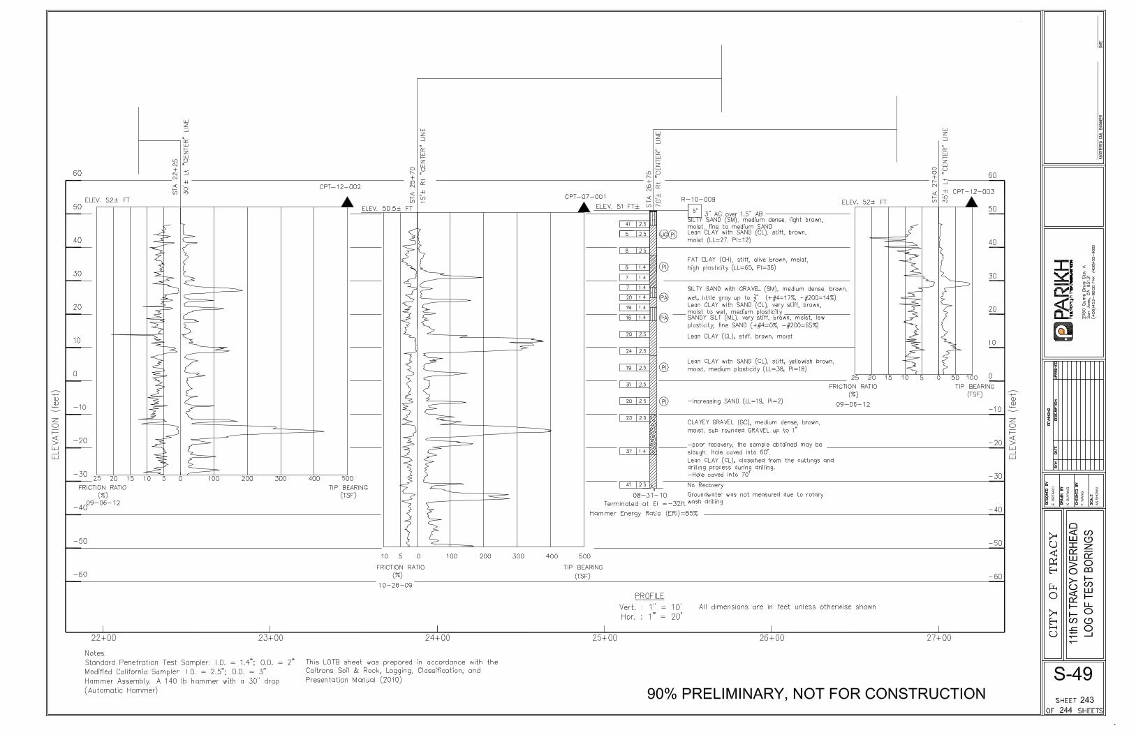
Based on CPT-12-002, CPT-12-003 and R-10-007 conducted in the vicinity of the proposed wall,
the foundation subgrade soils consist of medium stiff to stiff lean clay with sand. Groundwater
was encountered between Elev. 36 feet to 39.6 feet during field exploration. The layer of soft to
medium stiff clay was encountered down to about Elev. 40 feet, which is close to the proposed
footing elevations. Therefore, it is recommended that the subgrade be over-excavated 3 feet
below the footing and replaced with compacted AB. This pad is expected to serve as a “load
distribution bridge” for reducing footing pressure and differential settlement. The boring data
indicate that the groundwater level is relatively close to the proposed footing elevation.
Consequently, should groundwater be encountered during excavation, Lean Concrete Base
(LCB) may be used instead of compacted AB for the backfill below the footing.
Drake Haglan & Associates
Job No. 2005-151-PSE (11th
Street OH)
March 25th
, 2014
Page 19
It is expected that ground settlement will be induced due to the construction of the MSE wall and
the embankment, which is about 16 feet away from the proposed Retaining Wall No. 5.
Therefore, it is recommended that the MSE wall and embankment be constructed first prior to the
construction of the retaining wall. The same waiting period as recommended in Section 11.4.2
should be applied.
With the recommended subgrade improvement, the recommended ultimate bearing capacity at
the bottom of the footing is 8 ksf under extreme limit state, and a bearing capacity of 3.6 ksf is
recommended under strength limit state. The estimated settlement under the effective width and
the footing pressure under service condition is on the order of 1.5 inches. In our opinion, Caltrans
standard Type 5 retaining wall is considered feasible.
12.0 STRUCTURAL PAVEMENT DESIGN
Based on the roadway profile provided by the designer, 11th
Street is an elevated roadway,
crossing over the existing UPRR tracks, and approach embankments are planned along the project
alignment. New pavement will be constructed mostly on import borrow materials. It is
recommended that the materials placed within 4 feet of the finish pavement subgrade be free of
organic or other deleterious materials and have minimum R-value of 15.
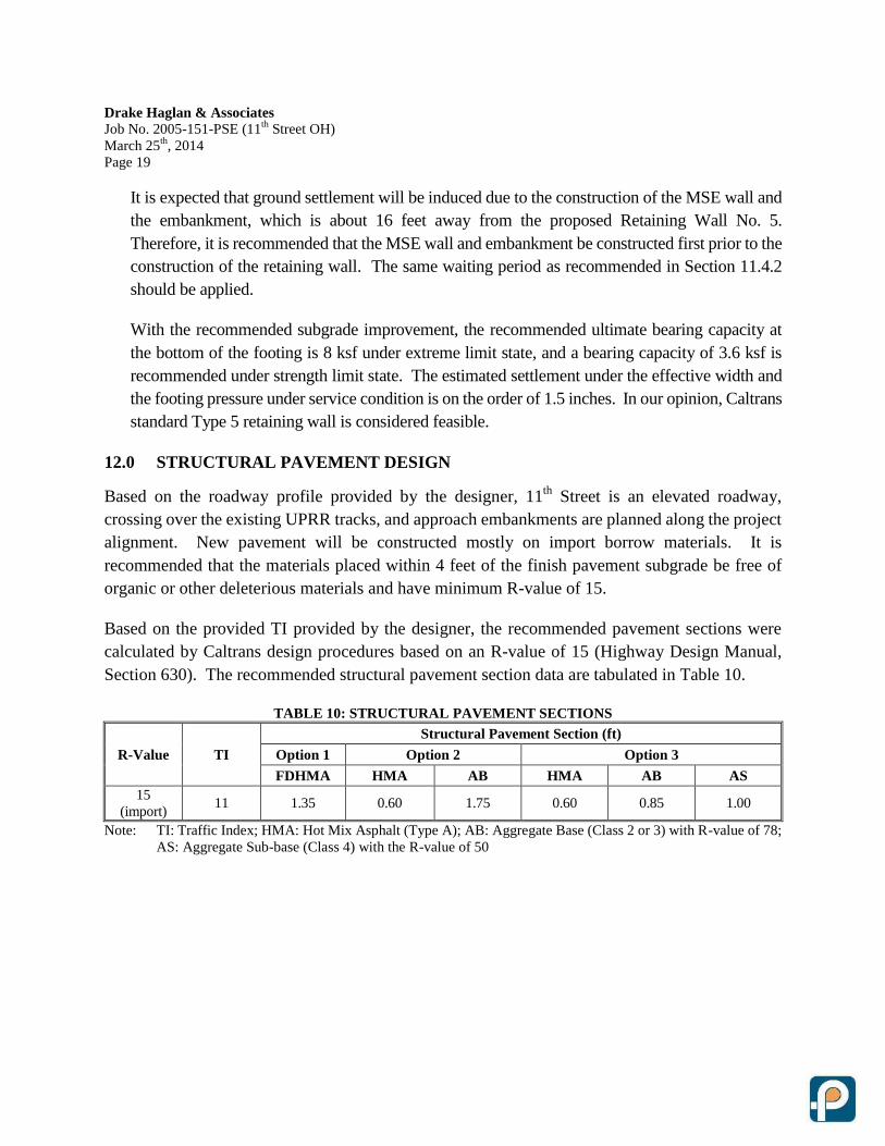
Based on the provided TI provided by the designer, the recommended pavement sections were
calculated by Caltrans design procedures based on an R-value of 15 (Highway Design Manual,
Section 630). The recommended structural pavement section data are tabulated in Table 10.
TABLE 10: STRUCTURAL PAVEMENT SECTIONS
R-Value TI
Structural Pavement Section (ft)
Option 1 Option 2 Option 3
FDHMA HMA AB HMA AB AS
15
(import) 11 1.35 0.60 1.75 0.60 0.85 1.00
Note: TI: Traffic Index; HMA: Hot Mix Asphalt (Type A); AB: Aggregate Base (Class 2 or 3) with R-value of 78;
AS: Aggregate Sub-base (Class 4) with the R-value of 50
Drake Haglan & Associates
Job No. 2005-151-PSE (11th
Street OH)
March 25th
, 2014
Page 20
13.0 NOTES TO DESIGNER
It is recommended that the structure engineer verify the pile tip elevations when finalizing the pile
data table. Should the specified pile tip elevation required to meet lateral load demands exceed the
specified pile tip elevation given within this report, the Geotechnical Engineer must be contacted
for further recommendations.
14.0 CONSTRUCTION CONSIDERATIONS
General 14.1
To a degree, the performance of any structure is dependent upon construction procedures and
quality. Hence, observation of grading operations should be carried out by Caltrans and/or City
of Tracy. If the encountered subsurface conditions differ from those forming the basis of our
recommendations, this office should be informed in order to assess the need for design
changes. Therefore, the recommendations presented in this report are contingent upon good
quality control and these geotechnical observations during construction.
Construction of CIDH Concrete Piles 14.2
Caltrans standard specification for “Cast-in-Place Concrete Piling” should apply for the
construction of CIDH piles. Groundwater is expected during pile construction. The use of
temporary casing and slurry construction for CIDH pile installation is anticipated.
For the proposed CIDH piles, temporary casing is recommended to minimize the construction
difficulty due to potential raveling or caving. In our opinion, the use of casing
oscillator/rotator techniques for CIDH construction may be considered to facilitate the pile
construction. This method has been successfully adopted in various projects throughout
California.
Access tubes should be provided to allow for construction quality control (Gamma-Gamma
Logging and/or Cross-Hole Sonic Logging). Due to presence of granular material, raveling or
caving is expected which may require additional drilling and cleaning effort and may increase
the concrete volume for the piles. It is prudent to make the contractor aware of these
conditions so that he takes appropriate steps to comply with the standards and maintain the
integrity of the CIDH concrete piles. Mitigation and repair procedures for CIDH anomaly
should be anticipated.
All piles excavations should be observed by the geotechnical engineer or regulatory agency
prior to the placement of reinforcement and concrete so that if conditions differ from those
anticipated, appropriate recommendations can be made.
Drake Haglan & Associates
Job No. 2005-151-PSE (11th
Street OH)
March 25th
, 2014
Page 21
Settlement Monitoring 14.3
The settlement monitoring should be implemented per Caltrans Test Method 112. It is
recommended that the settlement points be installed along the center line of the embankment at
a 100-foot interval and extend to 500 feet from the abutment. Additional settlement points at
the proposed foundation location are also recommended to verify or shorten the recommended
waiting period in order to commence the foundation construction.
Demolition of the Existing Foundation 14.4
The proposed new overhead structure and MSE walls will be constructed along the same
alignment as the existing structure, which is a 34-span structure supported on pile foundation.
The proposed location of the new foundation should be selected away from the existing footing
to avoid conflict. In addition, if any existing pile is located under the leveling pad of the MSE
walls, the top of the piles should be demolished to have minimum 3 feet clearance from the
bottom of the leveling pad.
15.0 INVESTIGATION LIMITATIONS
Our services consist of professional opinions and recommendations made in accordance with
generally accepted geotechnical engineering principles and practices and are based on our site
reconnaissance and the assumption that the subsurface conditions do not deviate from observed
conditions. All work done is in accordance with generally accepted geotechnical engineering
principles and practices. No warranty, expressed or implied, of merchantability or fitness, is made
or intended in connection with our work or by the furnishing of oral or written reports or findings.
The scope of our services did not include any environmental assessment or investigation for the
presence or absence of hazardous or toxic materials in structures, soil, surface water, groundwater
or air, below or around this site. Unanticipated soil conditions are commonly encountered and
cannot be fully determined by taking soil samples and excavating test borings; different soil
conditions may require that additional expenditures be made during construction to attain a
properly constructed project. Some contingency fund is thus recommended to accommodate these
possible extra costs.
This report has been prepared for the proposed project as described earlier, to assist the engineer in
the design of this project. In the event any changes in the design or location of the facilities are
planned, or if any variations or undesirable conditions are encountered during construction, our
conclusions and recommendations shall not be considered valid unless the changes or variations
are reviewed and our recommendations modified or approved by us in writing.
Drake Haglan & Associates
Job No. 2005-151-PSE (11th
Street OH)
March 25th
, 2014
Page 22
This report is issued with the understanding that it is the designer's responsibility to ensure that the
information and recommendations contained herein are incorporated into the project and that
necessary steps are also taken to see that the recommendations are carried out in the field.
The findings in this report are valid as of the present date. However, changes in the subsurface
conditions can occur with the passage of time, whether they are due to natural processes or to the
works of man, on this or adjacent properties. In addition, changes in applicable or appropriate
standards occur, whether they result from legislation or from the broadening of knowledge.
Accordingly, the findings in this report might be invalidated, wholly or partially, by changes
outside of our control.
Respectfully submitted,
PARIKH CONSULTANTS, INC.
Emre Ortakci, P.E. C76040
Project Engineer
Frank Wang, P.E., G.E. 2862 Gary Parikh, P.E., G.E. 666
Senior Project Engineer Project Manager
{11th OH - Foundation Report_2014-03-25}
Drake Haglan & Associates
Job No. 2005-151-PSE (11th
Street OH)
March 25th
, 2014
Page 23
REFERENCES
California Amendments to AASHTO LRFD Bridge Design Specifications, 4th
Edition,
dated September 2010
Caltrans, ARS Online (V1.0.4), http://dap3.dot.ca.gov/shake_stable/.
Caltrans Guidelines on Foundation Loading and Deformation Due to Liquefaction Induced Lateral
Spreading, February 2011
Caltrans Seismic Design Criteria, V1.6, November 2010
Caltrans, “Corrosion Guidelines”, Version 1.0, dated September 2003.
Caltrans, “Geotechnical Services Design Manual”, Version 1.0, dated August 2010.
Caltrans, “Foundation Report Preparation for Bridges”, dated December 2009.
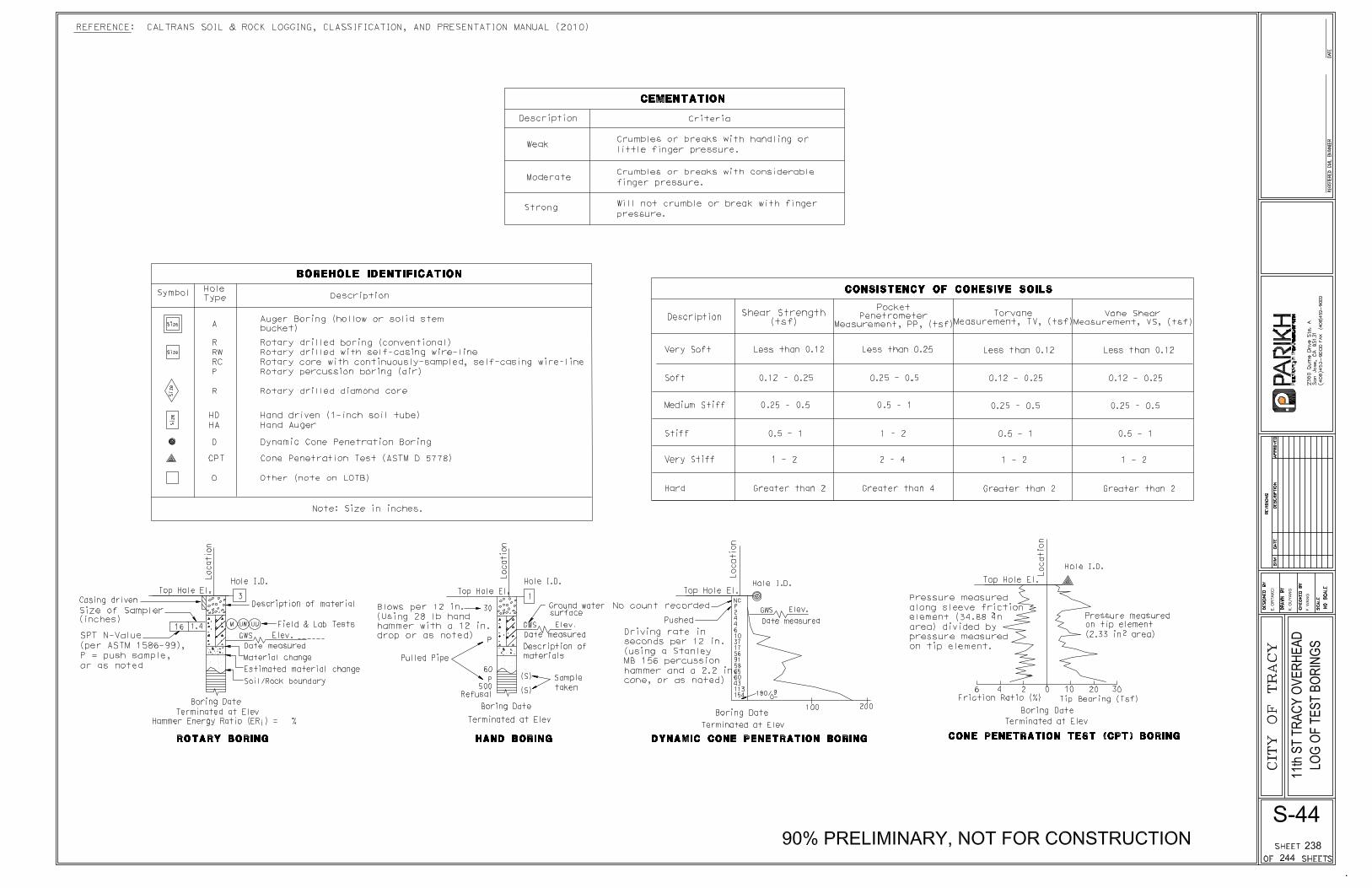
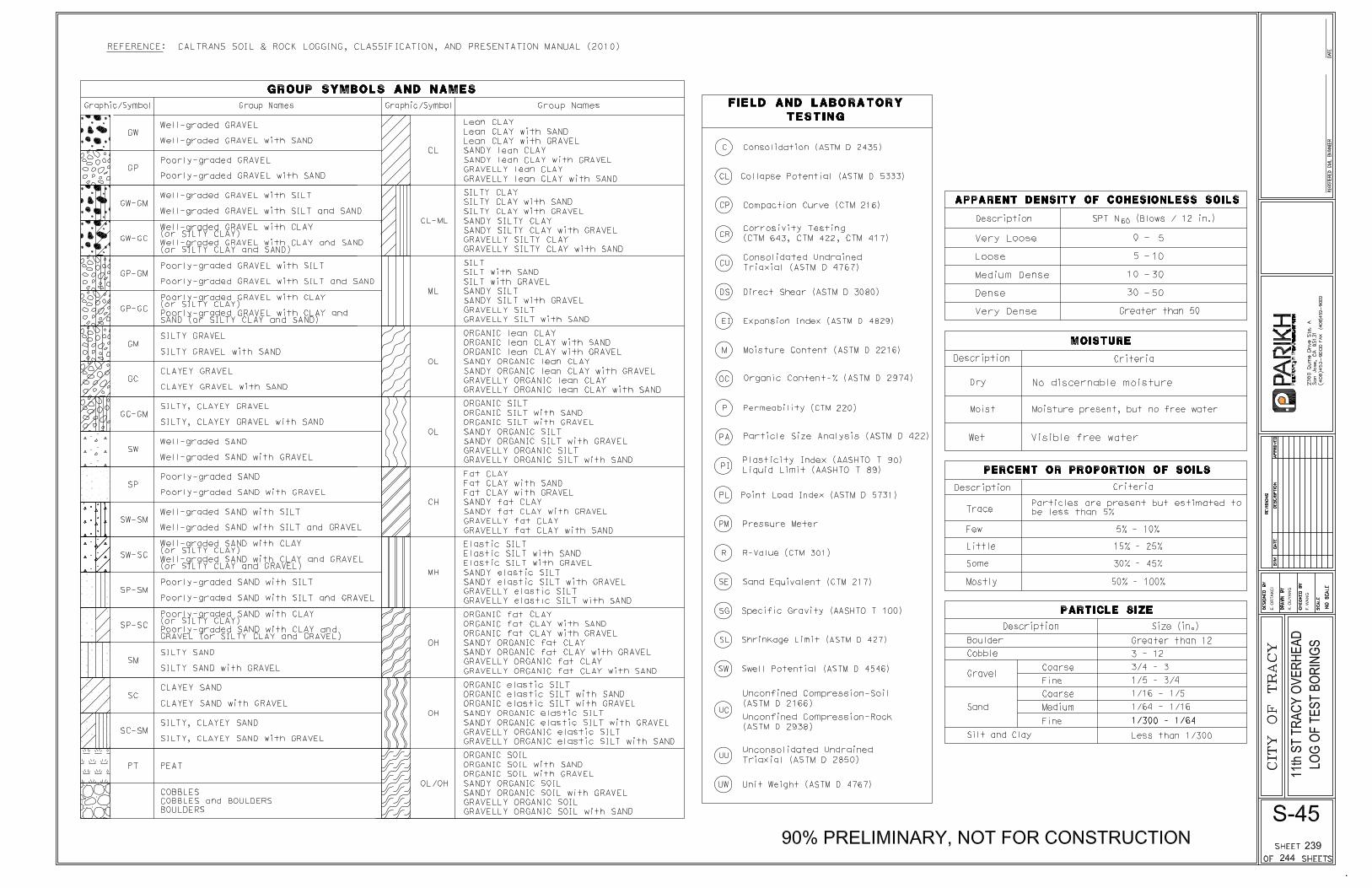
Caltrans, “Soil and Rock Logging, Classification and Presentation Manual”, dated July 2010.
D. L. Wagner, E. J. Bortugno and R. D. McJunkin, “Geologic Map of the San Francisco – San Jose
Quadrangle”, CDMG, Map No. 5A, dated 1990.
Youd, T.L., Idriss, I.M., Andrus, R.D., Arango, I., Castro, G., Christian, J.T., Dobry, R., Liam
Finn, W.D., Harder, L.F., Hynes, M.E., Ishihara, K., Koester, J.P., Liao, S.S.C., Marcuson,
W.F., III, Martin, G.R., Mitchell, J.K., Moriwaki, Power, M.S., Robertson, P.K., Seed,
R.B., Stokoe, K.H., II, “Liquefaction Resistance of Soils: Summary Report from the 1996
NCEER and 1998 NCEER/NSF Workshops on Evaluation of Liquefaction Resistance of
Soils, “ Journal of Geotechnical and Geoenvironmental Engineering, ASCE, V. 127, No.
10., 2001
APPENDIX I
PARIKH CONSULTANTS, INC.GEOTECHNICAL CONSULTANTSMATERIALS TESTING
11TH STREET EAST TRACY OVERHEADTRACY, CALIFORNIA
JOB NO.: 2005-151-PSE PLATE NO.: I-1
SITE MAP
ApproximateProject Location
PARIKH CONSULTANTS, INC.GEOTECHNICAL CONSULTANTSMATERIALS TESTING JOB NO.: 2005-151-PSE PLATE NO.: I-2
11TH STREET EAST TRACY OVERHEADTRACY, CALIFORNIA
GEOLOGIC MAP
Source: Geologic Map of the San Francisco – San Jose Quadrangle, by D. L. Wagner, E. J. Bortugno and R. D. McJunkin (CDMG, Map No. 5A, 1990)
ApproximateProject Location
Legend:

APPENDIX II
� � � � � � � � � � �� � � � � � � � � � � � � � � � � � � � � � � � � � � � � � � � � � � � � � � � � � � � � � � � � � � � � �� � � � � � � � � � � � � � � � � � � � � � � � � � � � � � � � � � � ! � � � � � � � � � � � � � � � � � � � � � � �� " # � � � � � � � � � � � � � � ! � � � $ � � � � � � � � � � � � � % � � � ! � � � � � # � � � � � � � � � � � � � � � � �� � � % � � � � � � � � � � � ! � � � � � � � � � � � � � � � � � � � � � � � � � � � � � � # � � � � �& ' ( ) * + , - . ) / 0 , - ) 1 2 ' 3 , 4 1 ) 1 0 5 , ( ) 6 ) , ) 7 3 5 0 , 8 1 + ) ( 9 : : ;. < * ) < ; = >( 9 : : ; ?@ A A @ A AB B C D E F G H H F H I E F F G I J K L M H G N H I OP L Q L R F H E F S L G T U Q E� � � V � � � � � � � � � � � � � � � � � � � � � � � � � � � � � � � � ! �� � # � � ! � � � � � � � � � � � � � � � � � � � � � # � � � � � � � �� � � � � � � � � � � # � � � � � # � � � � � � � � W X Y Z [ \ ] ^ _` a Y b b ` X c d ` c X \ b a \ \ ` ] ^ _ b e f g` h i j j h k l i m n l o i m p q i r s q
APPENDIX III
GREGG IN SITU, INC.
GEOTECHNICAL AND ENVIRONMENTAL INVESTIGATION SERVICES
950 Howe Rd • Martinez, California 94553 • (925) 313-5800 • FAX (925) 313-0302 OTHER OFFICES: LOS ANGELES • HOUSTON • SOUTH CAROLINA
www.greggdrilling.com
November 26, 2007 Parikh Consultants Attn: Gary Parikh 356 S. Milpitas Blvd. Milpitas, California 95035 Subject: CPT Site Investigation 11th St. Overhead Tracy, California GREGG Project Number: 07-349MA Dear Mr. Parikh: The following report presents the results of GREGG Drilling & Testing’s Cone Penetration Test investigation for the above referenced site. The following testing services were performed:
1 Cone Penetration Tests (CPTU) 2 Pore Pressure Dissipation Tests (PPD) 3 Seismic Cone Penetration Tests (SCPTU) 4 Resistivity Cone Penetration Tests (RCPTU) 5 UVIF Cone Penetration Tests (UVIFCPTU) 6 Groundwater Sampling (GWS) 7 Soil Sampling (SS) 8 Vapor Sampling (VS) 9 Vane Shear Testing (VST) 10 SPT Energy Calibration (SPTE)
A list of reference papers providing additional background on the specific tests conducted is provided in the bibliography following the text of the report. If you would like a copy of any of these publications or should you have any questions or comments regarding the contents of this report, please do not hesitate to contact our office at (925) 313-5800. Sincerely, GREGG Drilling & Testing, Inc. Mary Walden Operations Manager
GREGG IN SITU, INC.
GEOTECHNICAL AND ENVIRONMENTAL INVESTIGATION SERVICES
950 Howe Rd • Martinez, California 94553 • (925) 313-5800 • FAX (925) 313-0302 OTHER OFFICES: LOS ANGELES • HOUSTON • SOUTH CAROLINA
www.greggdrilling.com
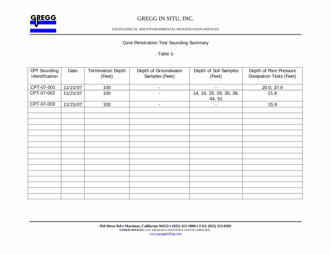
Cone Penetration Test Sounding Summary
-Table 1-
CPT Sounding Identification
Date Termination Depth (Feet)
Depth of Groundwater Samples (Feet)
Depth of Soil Samples (Feet)
Depth of Pore Pressure Dissipation Tests (Feet)
SCPT-01 11/21/07 100 - - 20.0, 37.9 CPT-02 11/21/07 100 - 14, 19, 25, 29, 35, 39,
44, 51 21.8
SCPT-03 11/21/07 100 - - 15.9
CPT-07-001CPT-07-002
CPT-07-003
GREGG IN SITU, INC.
GEOTECHNICAL AND ENVIRONMENTAL INVESTIGATION SERVICES
950 Howe Rd • Martinez, California 94553 • (925) 313-5800 • FAX (925) 313-0302 OTHER OFFICES: LOS ANGELES • HOUSTON • SOUTH CAROLINA
www.greggdrilling.com
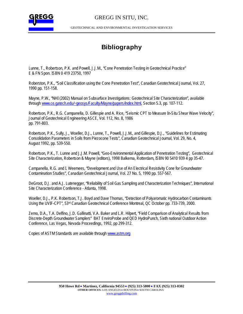
Bibliography Lunne, T., Robertson, P.K. and Powell, J.J.M., “Cone Penetration Testing in Geotechnical Practice” E & FN Spon. ISBN 0 419 23750, 1997 Roberston, P.K., “Soil Classification using the Cone Penetration Test”, Canadian Geotechnical Journal, Vol. 27, 1990 pp. 151-158. Mayne, P.W., “NHI (2002) Manual on Subsurface Investigations: Geotechnical Site Characterization”, available through www.ce.gatech.edu/~geosys/Faculty/Mayne/papers/index.html, Section 5.3, pp. 107-112. Robertson, P.K., R.G. Campanella, D. Gillespie and A. Rice, “Seismic CPT to Measure In-Situ Shear Wave Velocity”, Journal of Geotechnical Engineering ASCE, Vol. 112, No. 8, 1986 pp. 791-803. Robertson, P.K., Sully, J., Woeller, D.J., Lunne, T., Powell, J.J.M., and Gillespie, D.J., "Guidelines for Estimating Consolidation Parameters in Soils from Piezocone Tests", Canadian Geotechnical Journal, Vol. 29, No. 4, August 1992, pp. 539-550. Robertson, P.K., T. Lunne and J.J.M. Powell, “Geo-Environmental Application of Penetration Testing”, Geotechnical Site Characterization, Robertson & Mayne (editors), 1998 Balkema, Rotterdam, ISBN 90 5410 939 4 pp 35-47. Campanella, R.G. and I. Weemees, “Development and Use of An Electrical Resistivity Cone for Groundwater Contamination Studies”, Canadian Geotechnical Journal, Vol. 27 No. 5, 1990 pp. 557-567. DeGroot, D.J. and A.J. Lutenegger, “Reliability of Soil Gas Sampling and Characterization Techniques”, International Site Characterization Conference - Atlanta, 1998. Woeller, D.J., P.K. Robertson, T.J. Boyd and Dave Thomas, “Detection of Polyaromatic Hydrocarbon Contaminants Using the UVIF-CPT”, 53rd Canadian Geotechnical Conference Montreal, QC October pp. 733-739, 2000. Zemo, D.A., T.A. Delfino, J.D. Gallinatti, V.A. Baker and L.R. Hilpert, “Field Comparison of Analytical Results from Discrete-Depth Groundwater Samplers” BAT EnviroProbe and QED HydroPunch, Sixth national Outdoor Action Conference, Las Vegas, Nevada Proceedings, 1992, pp 299-312. Copies of ASTM Standards are available through www.astm.org
CPT-07-002
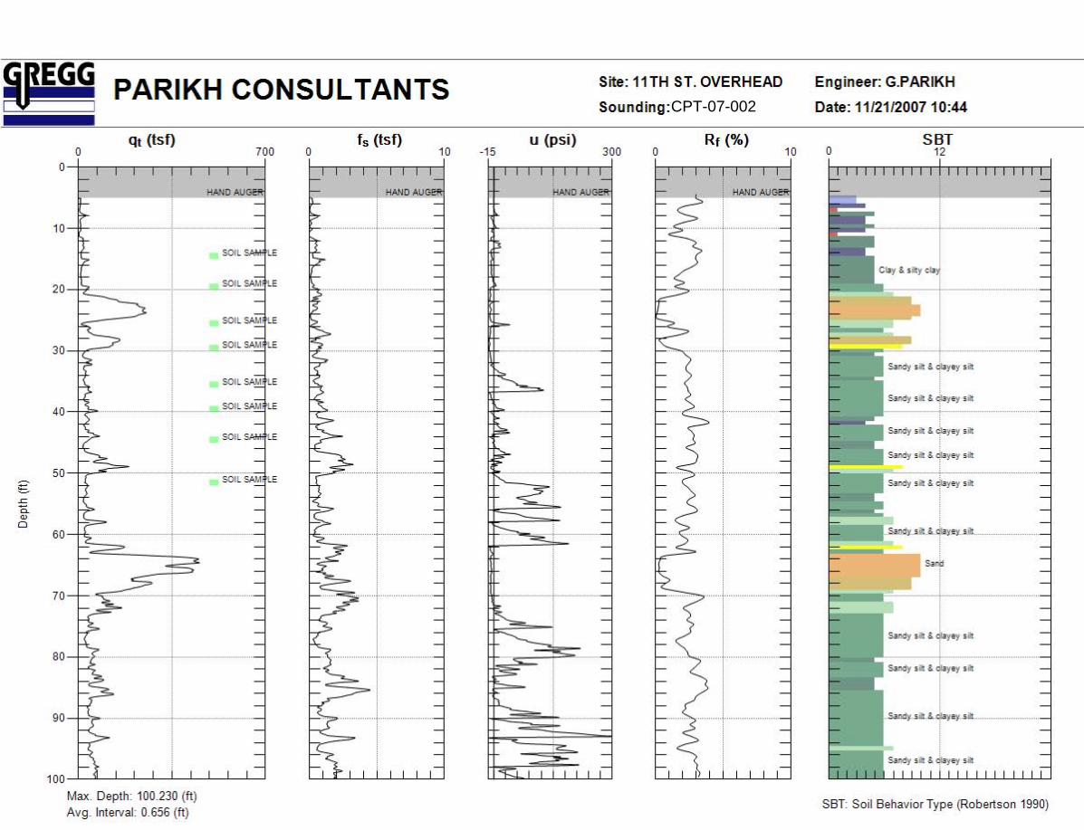
CPT-07-002

CPT-07-001
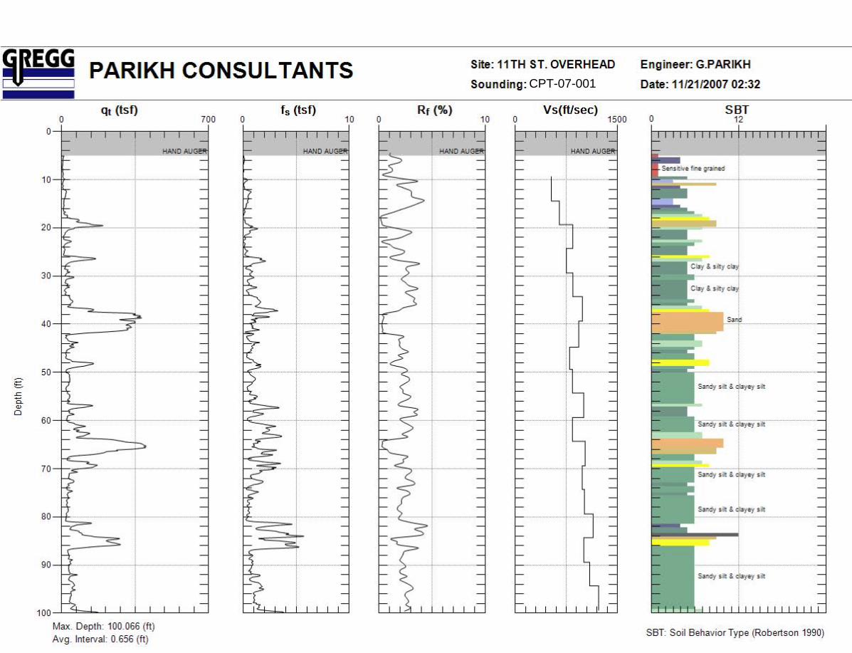
CPT-07-001
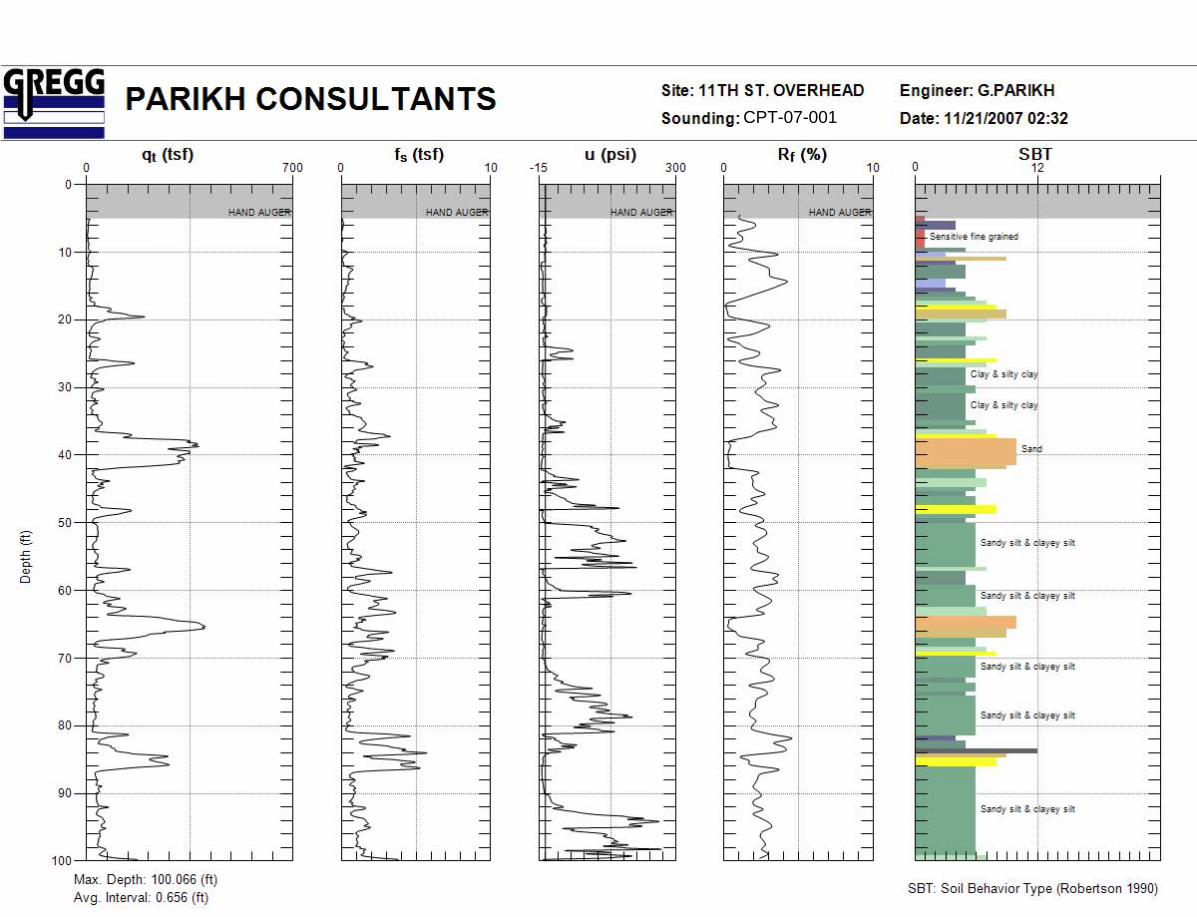
CPT-07-001

CPT-07-003
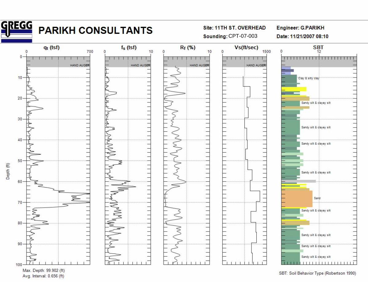
CPT-07-003
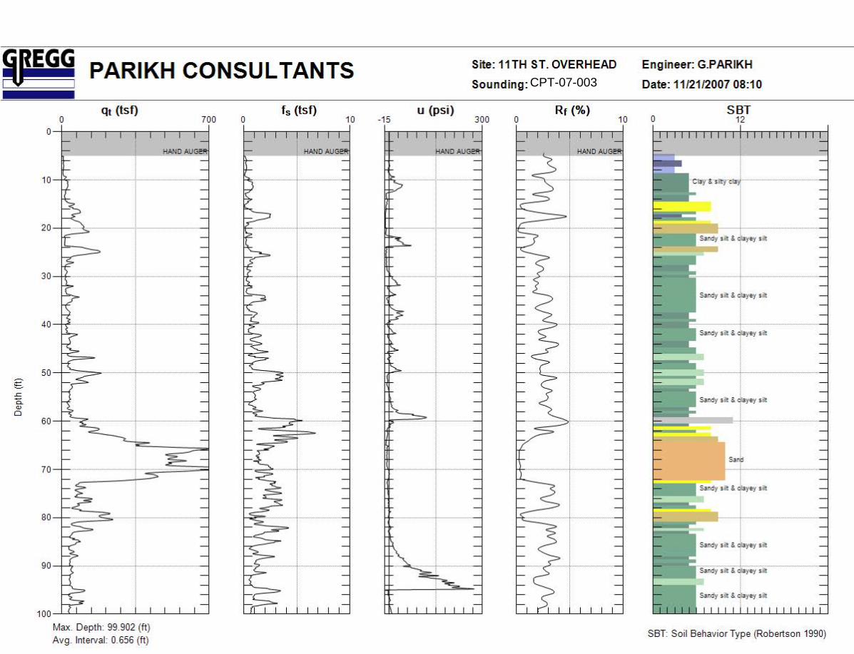
CPT-07-003

Geophone Offset: 0.66 Feet 11/21/2007Source Offset: 1.67 Feet
Test Depth (Feet)
Geophone Depth (Feet)
Waveform Ray Path
(Feet)
Incremental Distance
(Feet)
Characteristic Arrival Time
(ms)
Incremental Time Interval
(ms)
Interval Velocity (Ft/Sec)
Interval Depth (Feet)
10.01 9.35 9.49 9.49 23.200014.93 14.27 14.37 4.87 30.1500 6.9500 700.8 11.8120.01 19.35 19.42 5.06 35.5500 5.4000 937.0 16.8124.93 24.27 24.33 4.91 41.4500 5.9000 831.6 21.8130.02 29.36 29.41 5.08 47.2500 5.8000 875.1 26.8234.94 34.28 34.32 4.91 53.8000 6.5500 750.3 31.8240.68 40.02 40.06 5.74 60.7500 6.9500 825.3 37.1544.95 44.29 44.32 4.26 65.8000 5.0500 843.9 42.1550.03 49.37 49.40 5.08 72.3000 6.5000 781.9 46.8354.95 54.29 54.32 4.92 78.0500 5.7500 855.4 51.8360.04 59.38 59.40 5.08 83.1000 5.0500 1006.6 56.8465.12 64.46 64.49 5.08 88.5000 5.4000 941.4 61.9270.21 69.55 69.57 5.08 92.5000 4.0000 1270.9 67.0174.97 74.31 74.33 4.76 96.6500 4.1500 1146.0 71.9380.22 79.56 79.57 5.25 102.1000 5.4500 963.0 76.9384.97 84.31 84.33 4.76 106.3000 4.2000 1132.4 81.9390.06 89.40 89.41 5.08 110.7000 4.4000 1155.5 86.8694.98 94.32 94.33 4.92 115.7000 5.0000 984.1 91.86
100.07 99.41 99.42 5.08 120.7000 5.0000 1016.9 96.86
SCPT-3
Shear Wave Velocity Calculations11TH ST. OVERHEAD
CPT-07-003

Waveforms for Sounding SCPT-03
0
20
40
60
80
100
120
.0 20.0 40.0 60.0 80.0 100.0 120.0 140.0 160.0 180.0 200.0
Time (ms)
Dep
th (F
eet)
CPT-07-003
Geophone Offset: 0.66 Feet 11/21/2007Source Offset: 1.67 Feet
Test Depth (Feet)
Geophone Depth (Feet)
Waveform Ray Path
(Feet)
Incremental Distance
(Feet)
Characteristic Arrival Time
(ms)
Incremental Time Interval
(ms)
Interval Velocity (Ft/Sec)
Interval Depth (Feet)
10.01 9.35 9.49 9.49 24.200015.09 14.43 14.53 5.03 33.7000 9.5000 529.8 11.8920.01 19.35 19.42 4.90 41.2500 7.5500 648.6 16.8924.93 24.27 24.33 4.91 47.0500 5.8000 846.0 21.8130.02 29.36 29.41 5.08 53.8000 6.7500 751.9 26.8234.94 34.28 34.32 4.91 59.6000 5.8000 847.3 31.8240.03 39.37 39.40 5.08 64.7500 5.1500 986.4 36.8245.44 44.78 44.81 5.41 70.5500 5.8000 932.6 42.0750.03 49.37 49.40 4.59 76.3000 5.7500 798.3 47.0854.95 54.29 54.32 4.92 82.1500 5.8500 840.8 51.8360.04 59.38 59.40 5.08 87.2000 5.0500 1006.6 56.8464.96 64.30 64.32 4.92 93.0500 5.8500 840.9 61.8470.05 69.39 69.41 5.08 98.0000 4.9500 1027.0 66.8474.97 74.31 74.33 4.92 103.0000 5.0000 984.0 71.8580.05 79.39 79.41 5.08 108.0000 5.0000 1016.8 76.8584.97 84.31 84.33 4.92 112.3000 4.3000 1144.2 81.8590.06 89.40 89.41 5.08 117.3500 5.0500 1006.8 86.8694.98 94.32 94.33 4.92 121.8500 4.5000 1093.4 91.86
100.07 99.41 99.42 5.08 126.0000 4.1500 1225.2 96.86
SCPT-1
Shear Wave Velocity Calculations11TH ST. OVERHEAD
CPT-07-001
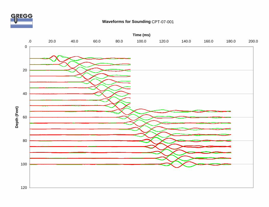
Waveforms for Sounding SCPT-01
0
20
40
60
80
100
120
.0 20.0 40.0 60.0 80.0 100.0 120.0 140.0 160.0 180.0 200.0
Time (ms)
Dep
th (F
eet)
CPT-07-001
GREGG DRILLING & TESTING, INC. GEOTECHNICAL AND ENVIRONMENTAL INVESTIGATION SERVICES
950 Howe Rd Martinez, California 94553 (925) 313-5800 FAX (925) 313-0302 www.greggdrilling.com
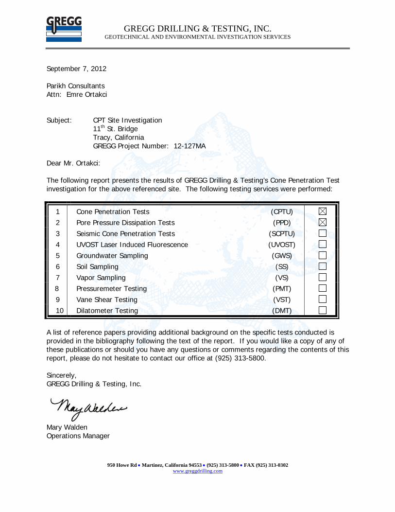
September 7, 2012 Parikh Consultants Attn: Emre Ortakci Subject: CPT Site Investigation 11th St. Bridge Tracy, California GREGG Project Number: 12-127MA Dear Mr. Ortakci: The following report presents the results of GREGG Drilling & Testing’s Cone Penetration Test investigation for the above referenced site. The following testing services were performed:
1 Cone Penetration Tests (CPTU) 2 Pore Pressure Dissipation Tests (PPD) 3 Seismic Cone Penetration Tests (SCPTU) 4 UVOST Laser Induced Fluorescence (UVOST) 5 Groundwater Sampling (GWS) 6 Soil Sampling (SS) 7 Vapor Sampling (VS) 8 Pressuremeter Testing (PMT) 9 Vane Shear Testing (VST) 10 Dilatometer Testing (DMT)
A list of reference papers providing additional background on the specific tests conducted is provided in the bibliography following the text of the report. If you would like a copy of any of these publications or should you have any questions or comments regarding the contents of this report, please do not hesitate to contact our office at (925) 313-5800. Sincerely, GREGG Drilling & Testing, Inc.
Mary Walden Operations Manager
GREGG DRILLING & TESTING, INC. GEOTECHNICAL AND ENVIRONMENTAL INVESTIGATION SERVICES
950 Howe Rd Martinez, California 94553 (925) 313-5800 FAX (925) 313-0302 www.greggdrilling.com
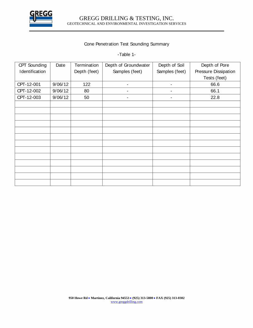
Cone Penetration Test Sounding Summary
-Table 1-
CPT Sounding Identification
Date Termination Depth (feet)
Depth of Groundwater Samples (feet)
Depth of Soil Samples (feet)
Depth of Pore Pressure Dissipation
Tests (feet) CPT-12-001 9/06/12 122 - - 66.6 CPT-12-002 9/06/12 80 - - 66.1 CPT-12-003 9/06/12 50 - - 22.8
GREGG DRILLING & TESTING, INC. GEOTECHNICAL AND ENVIRONMENTAL INVESTIGATION SERVICES
950 Howe Rd Martinez, California 94553 (925) 313-5800 FAX (925) 313-0302 www.greggdrilling.com
Bibliography Lunne, T., Robertson, P.K. and Powell, J.J.M., “Cone Penetration Testing in Geotechnical Practice” E & FN Spon. ISBN 0 419 23750, 1997 Roberston, P.K., “Soil Classification using the Cone Penetration Test”, Canadian Geotechnical Journal, Vol. 27, 1990 pp. 151-158. Mayne, P.W., “NHI (2002) Manual on Subsurface Investigations: Geotechnical Site Characterization”, available through www.ce.gatech.edu/~geosys/Faculty/Mayne/papers/index.html, Section 5.3, pp. 107-112. Robertson, P.K., R.G. Campanella, D. Gillespie and A. Rice, “Seismic CPT to Measure In-Situ Shear Wave Velocity”, Journal of Geotechnical Engineering ASCE, Vol. 112, No. 8, 1986 pp. 791-803. Robertson, P.K., Sully, J., Woeller, D.J., Lunne, T., Powell, J.J.M., and Gillespie, D.J., "Guidelines for Estimating Consolidation Parameters in Soils from Piezocone Tests", Canadian Geotechnical Journal, Vol. 29, No. 4, August 1992, pp. 539-550. Robertson, P.K., T. Lunne and J.J.M. Powell, “Geo-Environmental Application of Penetration Testing”, Geotechnical Site Characterization, Robertson & Mayne (editors), 1998 Balkema, Rotterdam, ISBN 90 5410 939 4 pp 35-47. Campanella, R.G. and I. Weemees, “Development and Use of An Electrical Resistivity Cone for Groundwater Contamination Studies”, Canadian Geotechnical Journal, Vol. 27 No. 5, 1990 pp. 557-567. DeGroot, D.J. and A.J. Lutenegger, “Reliability of Soil Gas Sampling and Characterization Techniques”, International Site Characterization Conference - Atlanta, 1998. Woeller, D.J., P.K. Robertson, T.J. Boyd and Dave Thomas, “Detection of Polyaromatic Hydrocarbon Contaminants Using the UVIF-CPT”, 53rd Canadian Geotechnical Conference Montreal, QC October pp. 733-739, 2000. Zemo, D.A., T.A. Delfino, J.D. Gallinatti, V.A. Baker and L.R. Hilpert, “Field Comparison of Analytical Results from Discrete-Depth Groundwater Samplers” BAT EnviroProbe and QED HydroPunch, Sixth national Outdoor Action Conference, Las Vegas, Nevada Proceedings, 1992, pp 299-312. Copies of ASTM Standards are available through www.astm.org
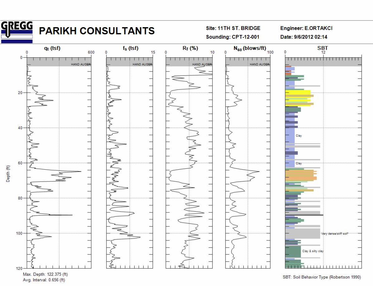
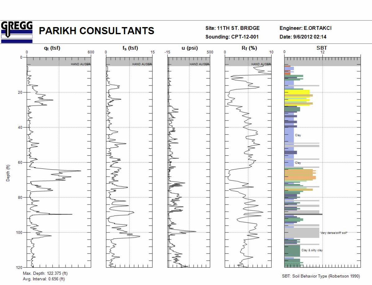

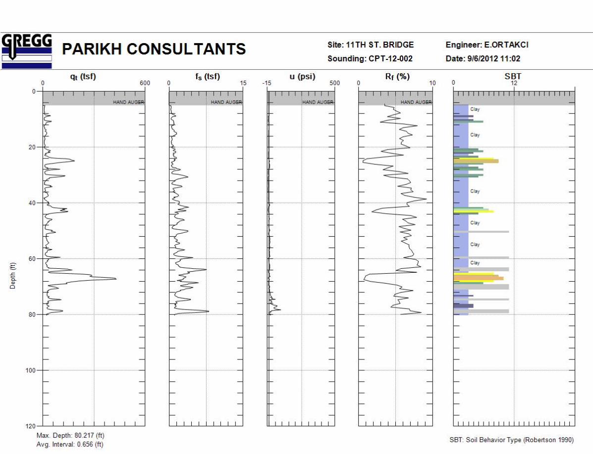
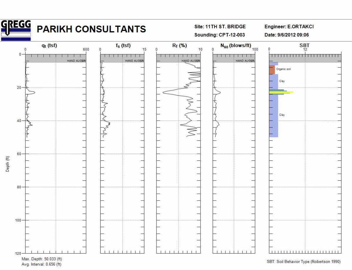
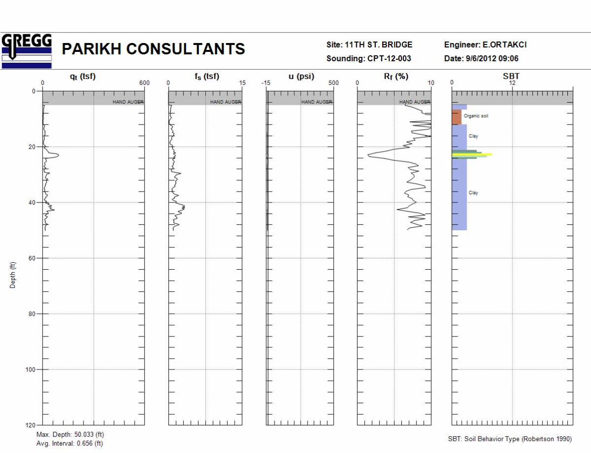

APPENDIX IV
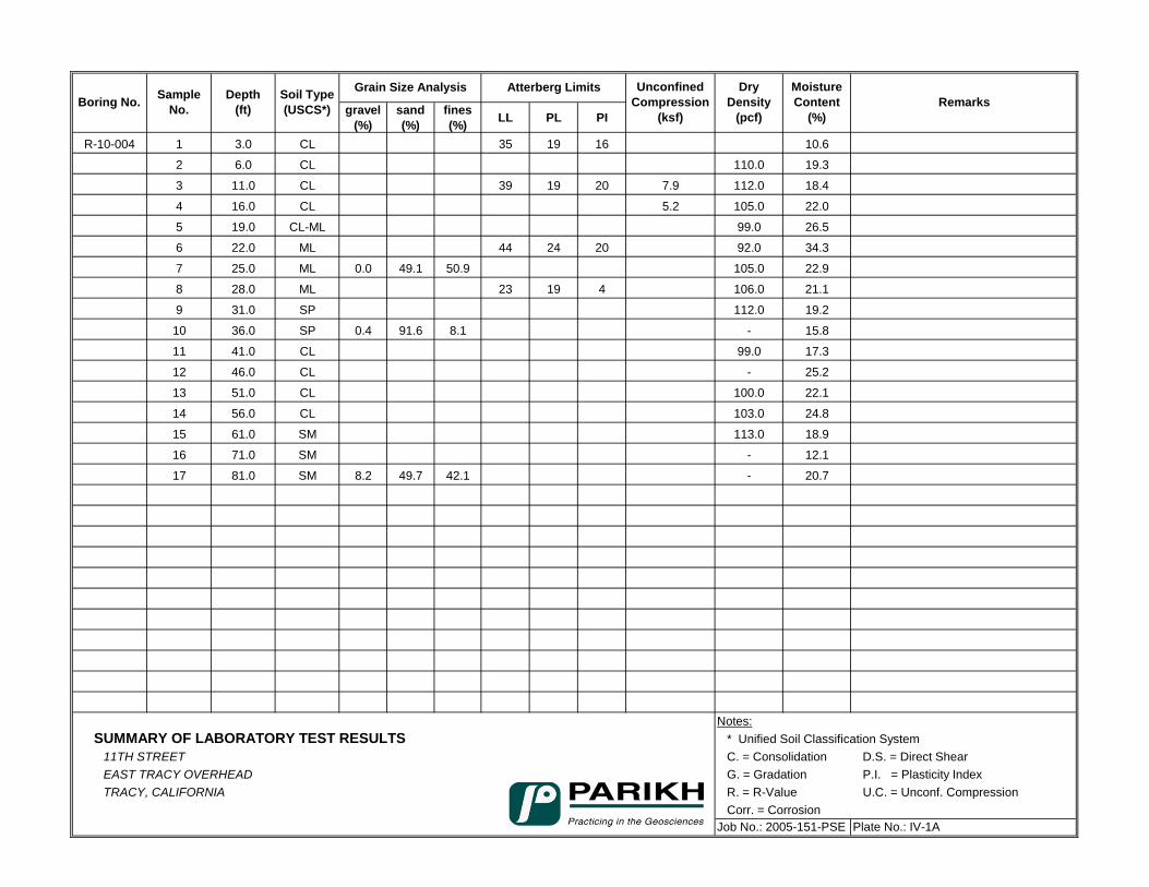
gravel (%)
sand (%)
fines (%) LL PL PI
R-10-004 1 3.0 CL 35 19 16 10.6
2 6.0 CL 110.0 19.3
3 11.0 CL 39 19 20 7.9 112.0 18.4
4 16.0 CL 5.2 105.0 22.0
5 19.0 CL-ML 99.0 26.5
6 22.0 ML 44 24 20 92.0 34.3
7 25.0 ML 0.0 49.1 50.9 105.0 22.9
8 28.0 ML 23 19 4 106.0 21.1
9 31.0 SP 112.0 19.2
10 36.0 SP 0.4 91.6 8.1 - 15.8
11 41.0 CL 99.0 17.3
12 46.0 CL - 25.2
13 51.0 CL 100.0 22.1
14 56.0 CL 103.0 24.8
15 61.0 SM 113.0 18.9
16 71.0 SM - 12.1
17 81.0 SM 8.2 49.7 42.1 - 20.7
Notes:SUMMARY OF LABORATORY TEST RESULTS * Unified Soil Classification System
11TH STREET C. = Consolidation D.S. = Direct ShearEAST TRACY OVERHEAD G. = Gradation P.I. = Plasticity IndexTRACY, CALIFORNIA R. = R-Value U.C. = Unconf. Compression
Corr. = Corrosion Job No.: 2005-151-PSE Plate No.: IV-1A
Atterberg Limits DryDensity
(pcf)
Moisture Content
(%)Remarks
Unconfined Compression
(ksf)Boring No. Depth
(ft)Sample
No.Soil Type (USCS*)
Grain Size Analysis
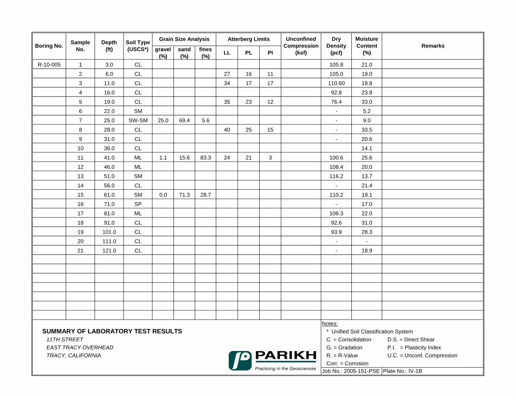
gravel (%)
sand (%)
fines (%) LL PL PI
R-10-005 1 3.0 CL 105.8 21.0
2 6.0 CL 27 16 11 105.0 19.0
3 11.0 CL 34 17 17 110.60 18.8
4 16.0 CL 92.8 23.8
5 19.0 CL 35 23 12 76.4 33.0
6 22.0 SM - 5.2
7 25.0 SW-SM 25.0 69.4 5.6 - 9.0
8 28.0 CL 40 25 15 - 33.5
9 31.0 CL - 20.6
10 36.0 CL 14.1
11 41.0 ML 1.1 15.6 83.3 24 21 3 100.6 25.6
12 46.0 ML 108.4 20.0
13 51.0 SM 116.2 13.7
14 56.0 CL - 21.4
15 61.0 SM 0.0 71.3 28.7 110.2 19.1
16 71.0 SP - 17.0
17 81.0 ML 106.3 22.0
18 91.0 CL 92.6 31.0
19 101.0 CL 93.9 28.3
20 111.0 CL - -
21 121.0 CL - 18.9
Notes:SUMMARY OF LABORATORY TEST RESULTS * Unified Soil Classification System
11TH STREET C. = Consolidation D.S. = Direct ShearEAST TRACY OVERHEAD G. = Gradation P.I. = Plasticity IndexTRACY, CALIFORNIA R. = R-Value U.C. = Unconf. Compression
Corr. = Corrosion Job No.: 2005-151-PSE Plate No.: IV-1B
Unconfined Compression
(ksf)
DryDensity
(pcf)
Moisture Content
(%)RemarksBoring No. Sample
No.Depth
(ft)Soil Type (USCS*)
Grain Size Analysis Atterberg Limits
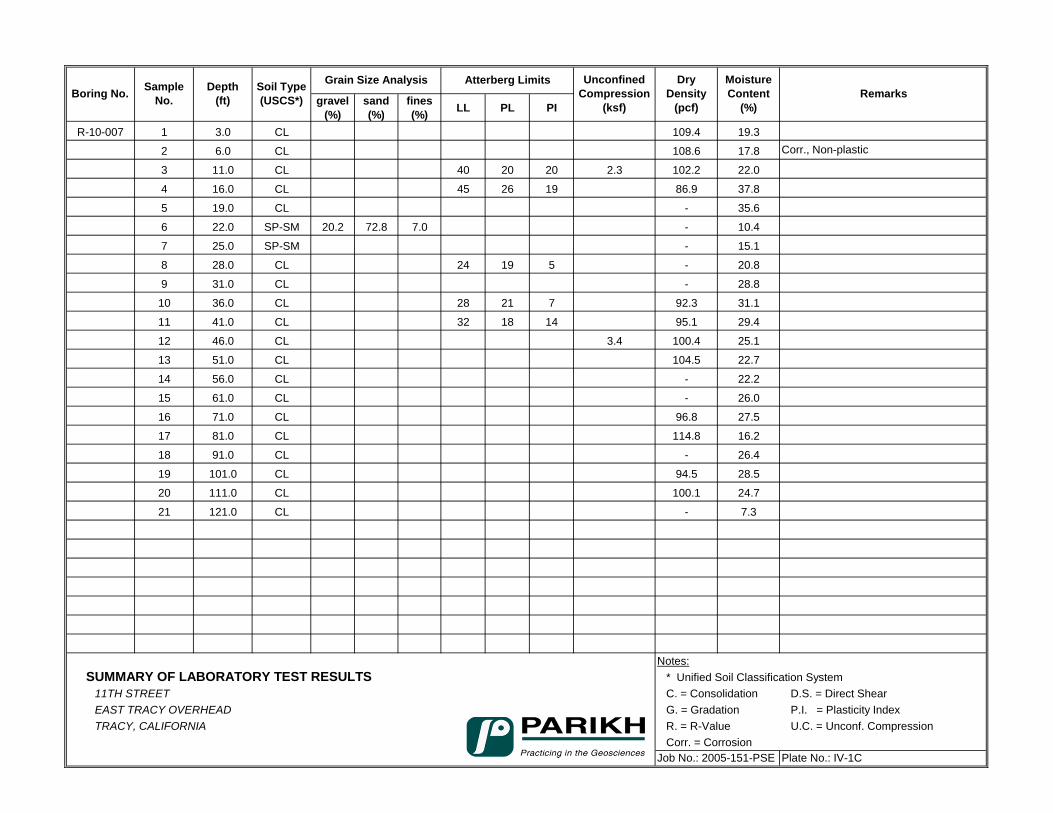
gravel (%)
sand (%)
fines (%) LL PL PI
R-10-007 1 3.0 CL 109.4 19.3
2 6.0 CL 108.6 17.8 Corr., Non-plastic
3 11.0 CL 40 20 20 2.3 102.2 22.0
4 16.0 CL 45 26 19 86.9 37.8
5 19.0 CL - 35.6
6 22.0 SP-SM 20.2 72.8 7.0 - 10.4
7 25.0 SP-SM - 15.1
8 28.0 CL 24 19 5 - 20.8
9 31.0 CL - 28.8
10 36.0 CL 28 21 7 92.3 31.1
11 41.0 CL 32 18 14 95.1 29.4
12 46.0 CL 3.4 100.4 25.1
13 51.0 CL 104.5 22.7
14 56.0 CL - 22.2
15 61.0 CL - 26.0
16 71.0 CL 96.8 27.5
17 81.0 CL 114.8 16.2
18 91.0 CL - 26.4
19 101.0 CL 94.5 28.5
20 111.0 CL 100.1 24.7
21 121.0 CL - 7.3
Notes:SUMMARY OF LABORATORY TEST RESULTS * Unified Soil Classification System
11TH STREET C. = Consolidation D.S. = Direct ShearEAST TRACY OVERHEAD G. = Gradation P.I. = Plasticity IndexTRACY, CALIFORNIA R. = R-Value U.C. = Unconf. Compression
Corr. = Corrosion Job No.: 2005-151-PSE Plate No.: IV-1C
Unconfined Compression
(ksf)
DryDensity
(pcf)
Moisture Content
(%)RemarksBoring No. Sample
No.Depth
(ft)Soil Type (USCS*)
Grain Size Analysis Atterberg Limits
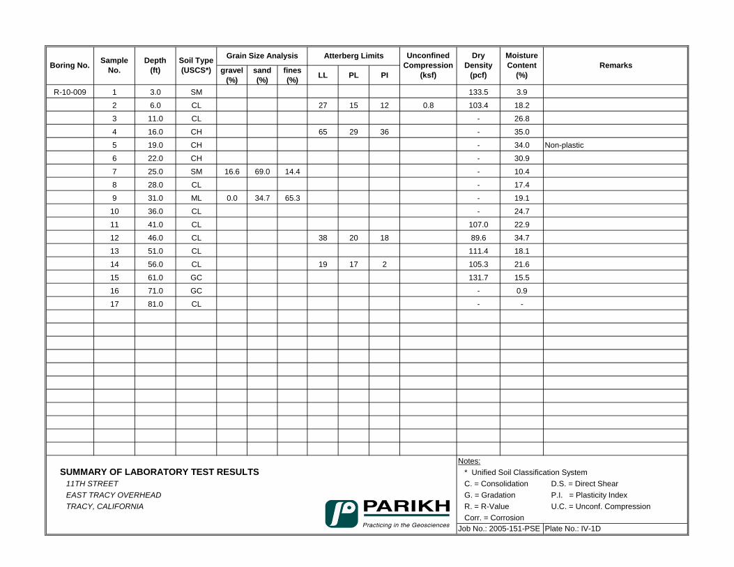
gravel (%)
sand (%)
fines (%) LL PL PI
R-10-009 1 3.0 SM 133.5 3.9
2 6.0 CL 27 15 12 0.8 103.4 18.2
3 11.0 CL - 26.8
4 16.0 CH 65 29 36 - 35.0
5 19.0 CH - 34.0 Non-plastic
6 22.0 CH - 30.9
7 25.0 SM 16.6 69.0 14.4 - 10.4
8 28.0 CL - 17.4
9 31.0 ML 0.0 34.7 65.3 - 19.1
10 36.0 CL - 24.7
11 41.0 CL 107.0 22.9
12 46.0 CL 38 20 18 89.6 34.7
13 51.0 CL 111.4 18.1
14 56.0 CL 19 17 2 105.3 21.6
15 61.0 GC 131.7 15.5
16 71.0 GC - 0.9
17 81.0 CL - -
Notes:SUMMARY OF LABORATORY TEST RESULTS * Unified Soil Classification System
11TH STREET C. = Consolidation D.S. = Direct ShearEAST TRACY OVERHEAD G. = Gradation P.I. = Plasticity IndexTRACY, CALIFORNIA R. = R-Value U.C. = Unconf. Compression
Corr. = Corrosion Job No.: 2005-151-PSE Plate No.: IV-1D
Unconfined Compression
(ksf)
DryDensity
(pcf)
Moisture Content
(%)RemarksBoring No. Sample
No.Depth
(ft)Soil Type (USCS*)
Grain Size Analysis Atterberg Limits
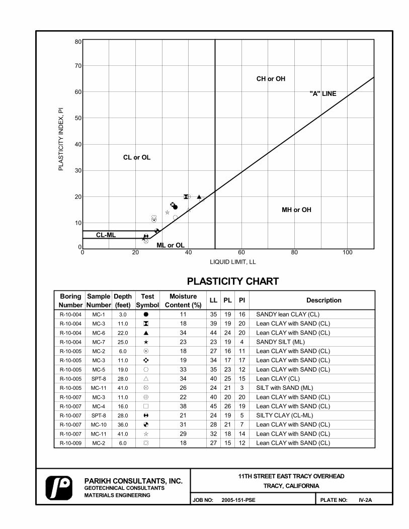
0
10
20
30
40
50
60
70
80
0 20 40 60 80 100
3.0
11.0
22.0
25.0
6.0
11.0
19.0
28.0
41.0
11.0
16.0
28.0
36.0
41.0
6.0
IV-2A
CL or OL
BoringNumber
SampleNumber
Depth(feet)
TestSymbol
MoistureContent (%)
CL-ML
CH or OH
MH or OH
PLA
ST
ICIT
Y IN
DE
X, P
I
"A" LINE
LIQUID LIMIT, LL
PLASTICITY CHART
11
18
34
23
18
19
33
34
26
22
38
21
31
29
18
PL PI Description
R-10-004
R-10-004
R-10-004
R-10-004
R-10-005
R-10-005
R-10-005
R-10-005
R-10-005
R-10-007
R-10-007
R-10-007
R-10-007
R-10-007
R-10-009
MC-1
MC-3
MC-6
MC-7
MC-2
MC-3
MC-5
SPT-8
MC-11
MC-3
MC-4
SPT-8
MC-10
MC-11
MC-2
ML or OL
35
39
44
23
27
34
35
40
24
40
45
24
28
32
27
19
19
24
19
16
17
23
25
21
20
26
19
21
18
15
16
20
20
4
11
17
12
15
3
20
19
5
7
14
12
SANDY lean CLAY (CL)
Lean CLAY with SAND (CL)
Lean CLAY with SAND (CL)
SANDY SILT (ML)
Lean CLAY with SAND (CL)
Lean CLAY with SAND (CL)
Lean CLAY with SAND (CL)
Lean CLAY (CL)
SILT with SAND (ML)
Lean CLAY with SAND (CL)
Lean CLAY with SAND (CL)
SILTY CLAY (CL-ML)
Lean CLAY with SAND (CL)
Lean CLAY with SAND (CL)
Lean CLAY with SAND (CL)
LL
PARIKH CONSULTANTS, INC.GEOTECHNICAL CONSULTANTSMATERIALS ENGINEERING
PLATE NO:
11TH STREET EAST TRACY OVERHEAD
TRACY, CALIFORNIA
2005-151-PSEJOB NO:
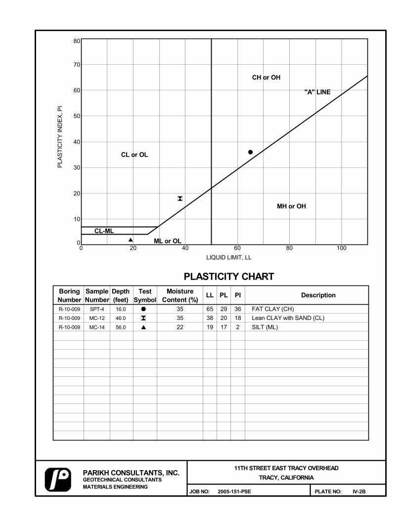
0
10
20
30
40
50
60
70
80
0 20 40 60 80 100
16.0
46.0
56.0
IV-2B
CL or OL
BoringNumber
SampleNumber
Depth(feet)
TestSymbol
MoistureContent (%)
CL-ML
CH or OH
MH or OH
PLA
ST
ICIT
Y IN
DE
X, P
I
"A" LINE
LIQUID LIMIT, LL
PLASTICITY CHART
35
35
22
PL PI Description
R-10-009
R-10-009
R-10-009
SPT-4
MC-12
MC-14
ML or OL
65
38
19
29
20
17
36
18
2
FAT CLAY (CH)
Lean CLAY with SAND (CL)
SILT (ML)
LL
PARIKH CONSULTANTS, INC.GEOTECHNICAL CONSULTANTSMATERIALS ENGINEERING
PLATE NO:
11TH STREET EAST TRACY OVERHEAD
TRACY, CALIFORNIA
2005-151-PSEJOB NO:
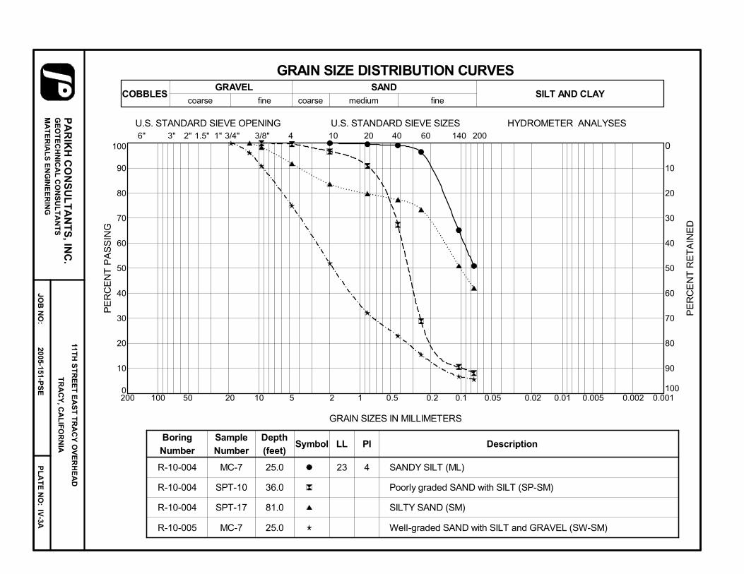
0
10
20
30
40
50
60
70
80
90
100
0.0010.010.1110100
R-10-004
R-10-004
R-10-004
R-10-005
MC-7
SPT-10
SPT-17
MC-7
25.0
36.0
81.0
25.0
23 4 SANDY SILT (ML)
Poorly graded SAND with SILT (SP-SM)
SILTY SAND (SM)
Well-graded SAND with SILT and GRAVEL (SW-SM)
Boring
Number
Sample
Number
Depth
(feet)Symbol
6" 3" 2" 1.5" 1" 3/4" 3/8" 4 10 20 40 60 140 200
COBBLESGRAVEL SAND
coarse fine coarse medium fineSILT AND CLAY
PE
RC
EN
T P
AS
SIN
G
PE
RC
EN
T R
ET
AIN
ED
GRAIN SIZES IN MILLIMETERS
0
10
20
30
40
50
60
70
80
90
100200 0.05 0.02 0.005 0.00250 20 5 2 0.5 0.2
U.S. STANDARD SIEVE SIZES HYDROMETER ANALYSESU.S. STANDARD SIEVE OPENING
GRAIN SIZE DISTRIBUTION CURVES
LL PI Description
PA
RIK
H C
ON
SU
LT
AN
TS
, INC
.11T
H S
TR
EE
T E
AS
T T
RA
CY
OV
ER
HE
AD
TR
AC
Y, C
AL
IFO
RN
IAG
EO
TE
CH
NIC
AL
CO
NS
UL
TA
NT
SM
AT
ER
IAL
S E
NG
INE
ER
ING
PL
AT
E N
O:
IV-3A
2005-151-PS
EJO
B N
O:
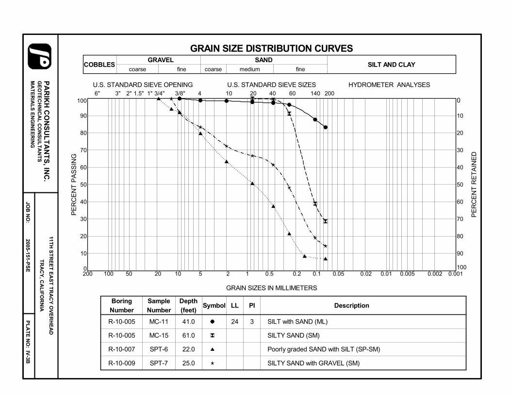
0
10
20
30
40
50
60
70
80
90
100
0.0010.010.1110100
R-10-005
R-10-005
R-10-007
R-10-009
MC-11
MC-15
SPT-6
SPT-7
41.0
61.0
22.0
25.0
24 3 SILT with SAND (ML)
SILTY SAND (SM)
Poorly graded SAND with SILT (SP-SM)
SILTY SAND with GRAVEL (SM)
Boring
Number
Sample
Number
Depth
(feet)Symbol
6" 3" 2" 1.5" 1" 3/4" 3/8" 4 10 20 40 60 140 200
COBBLESGRAVEL SAND
coarse fine coarse medium fineSILT AND CLAY
PE
RC
EN
T P
AS
SIN
G
PE
RC
EN
T R
ET
AIN
ED
GRAIN SIZES IN MILLIMETERS
0
10
20
30
40
50
60
70
80
90
100200 0.05 0.02 0.005 0.00250 20 5 2 0.5 0.2
U.S. STANDARD SIEVE SIZES HYDROMETER ANALYSESU.S. STANDARD SIEVE OPENING
GRAIN SIZE DISTRIBUTION CURVES
LL PI Description
PA
RIK
H C
ON
SU
LT
AN
TS
, INC
.11T
H S
TR
EE
T E
AS
T T
RA
CY
OV
ER
HE
AD
TR
AC
Y, C
AL
IFO
RN
IAG
EO
TE
CH
NIC
AL
CO
NS
UL
TA
NT
SM
AT
ER
IAL
S E
NG
INE
ER
ING
PL
AT
E N
O:
IV-3B
2005-151-PS
EJO
B N
O:
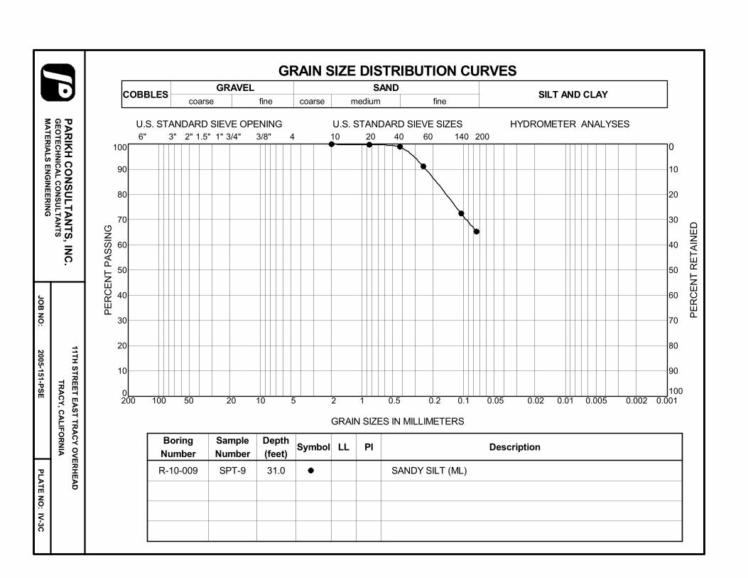
0
10
20
30
40
50
60
70
80
90
100
0.0010.010.1110100
R-10-009 SPT-9 31.0 SANDY SILT (ML)
Boring
Number
Sample
Number
Depth
(feet)Symbol
6" 3" 2" 1.5" 1" 3/4" 3/8" 4 10 20 40 60 140 200
COBBLESGRAVEL SAND
coarse fine coarse medium fineSILT AND CLAY
PE
RC
EN
T P
AS
SIN
G
PE
RC
EN
T R
ET
AIN
ED
GRAIN SIZES IN MILLIMETERS
0
10
20
30
40
50
60
70
80
90
100200 0.05 0.02 0.005 0.00250 20 5 2 0.5 0.2
U.S. STANDARD SIEVE SIZES HYDROMETER ANALYSESU.S. STANDARD SIEVE OPENING
GRAIN SIZE DISTRIBUTION CURVES
LL PI Description
PA
RIK
H C
ON
SU
LT
AN
TS
, INC
.11T
H S
TR
EE
T E
AS
T T
RA
CY
OV
ER
HE
AD
TR
AC
Y, C
AL
IFO
RN
IAG
EO
TE
CH
NIC
AL
CO
NS
UL
TA
NT
SM
AT
ER
IAL
S E
NG
INE
ER
ING
PL
AT
E N
O:
IV-3C
2005-151-PS
EJO
B N
O:
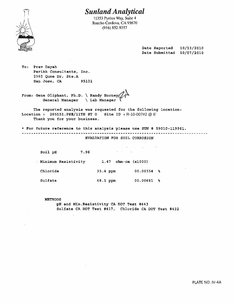
R-10-007#2 @ 6'
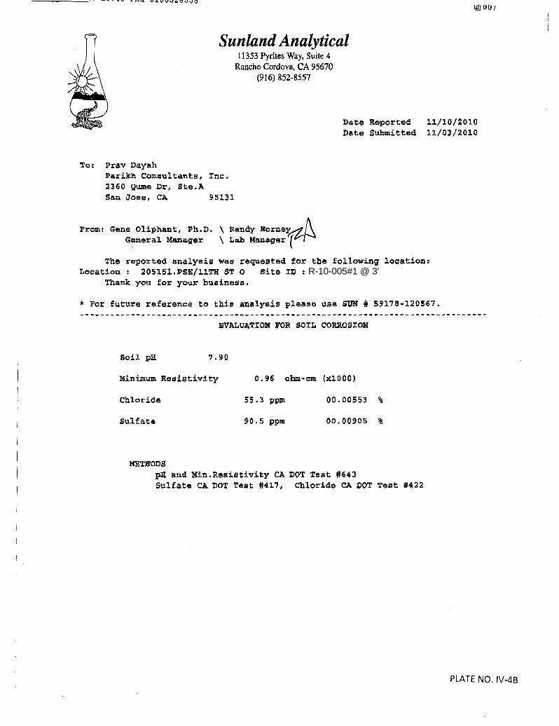
R-10-005#1 @ 3'
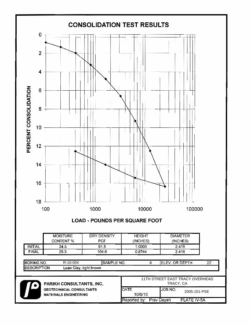
R-10-004
11TH STREET EAST TRACY OVERHEAD TRACY, CA
2005-151-PSE

R-10-005
11TH STREET EAST TRACY OVERHEAD TRACY, CA
2005-151-PSE
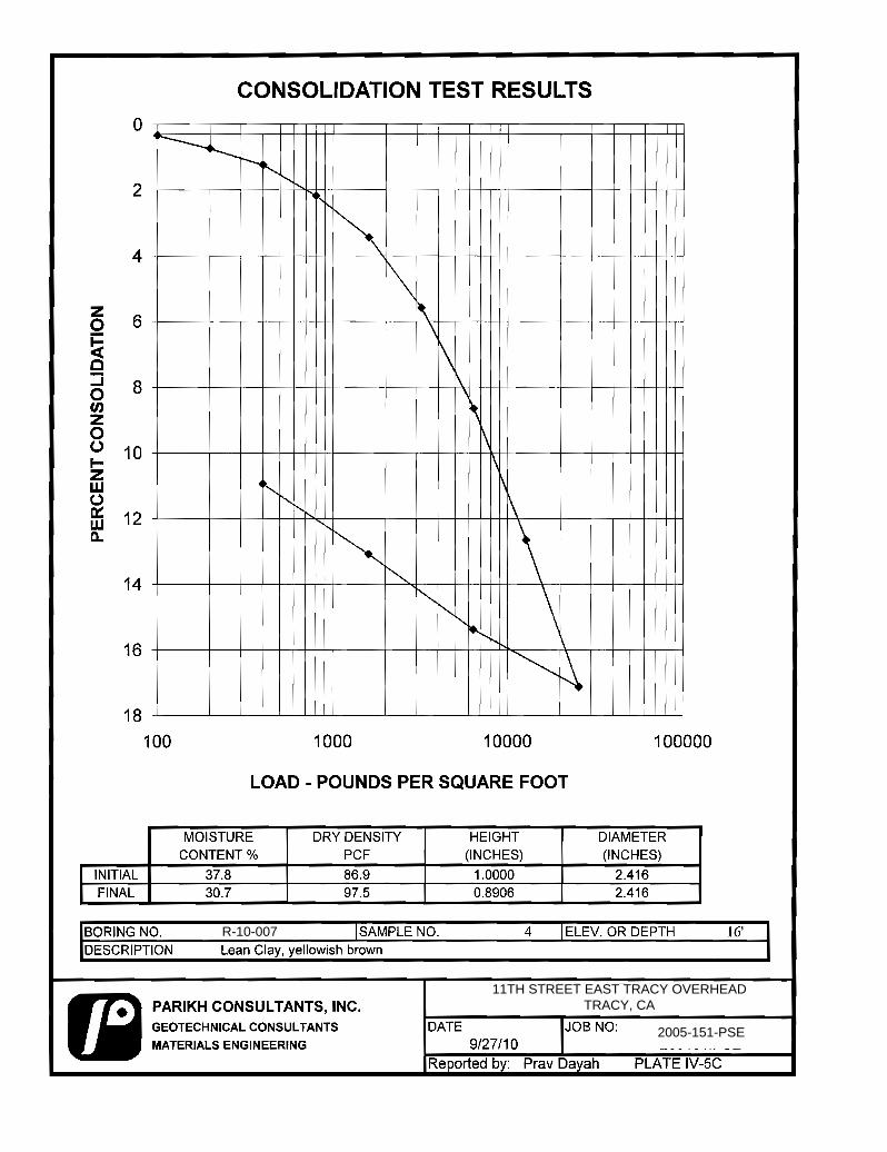
R-10-007
11TH STREET EAST TRACY OVERHEAD TRACY, CA
2005-151-PSE
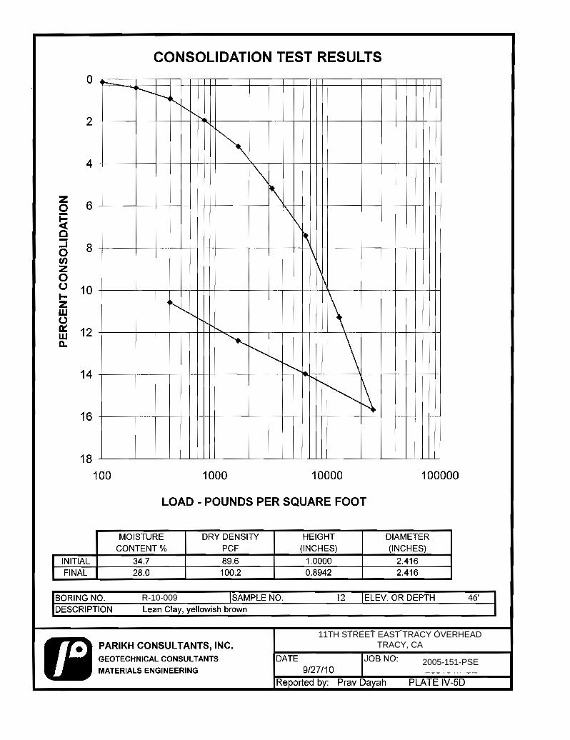
R-10-009
11TH STREET EAST TRACY OVERHEAD TRACY, CA
2005-151-PSE

APPENDIX V
FAULT MAP & ARS CURVES

PARIKH CONSULTANTS, INC.GEOTECHNICAL CONSULTANTSMATERIALS TESTING
11TH STREET EAST TRACY OVERHEADTRACY, CALIFORNIA
JOB NO.: 2005-151-PSE PLATE NO.: V-1
FAULT MAP
Legend25 - Great Valley Fault 7 (R)26 - Great Valley Fault 8 (R)350 - Greenville Fault Zone (Arroyo Mocho Section) (RLSS)352 - Greenville Fault Zone (Marsh Creek-Greenville Section) (RLSS)
Source: "2007 Caltrans Deterministic PGA Map FID shown September
0 15 30 miles
ApproximateProject Location
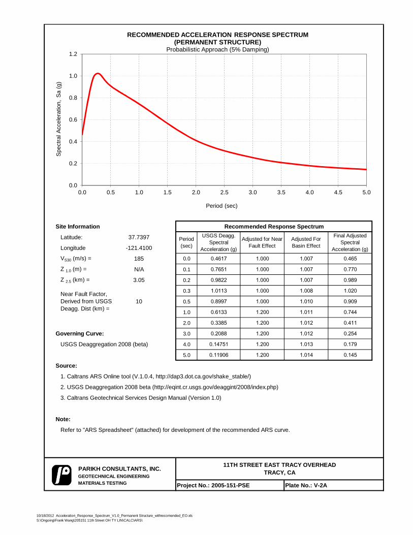
Site Information Recommended Response Spectrum
Latitude: 37.7397
Longitude -121.4100
VS30 (m/s) = 185 0.0 0.4617 1.000 1.007 0.465
Z 1.0 (m) = N/A 0.1 0.7651 1.000 1.007 0.770
Z 2.5 (km) = 3.05 0.2 0.9822 1.000 1.007 0.989
0.3 1.0113 1.000 1.008 1.020
10 0.5 0.8997 1.000 1.010 0.909
1.0 0.6133 1.200 1.011 0.744
2.0 0.3385 1.200 1.012 0.411
Governing Curve: 3.0 0.2088 1.200 1.012 0.254
USGS Deaggregation 2008 (beta) 4.0 0.14751 1.200 1.013 0.179
5.0 0.11906 1.200 1.014 0.145
Source:
1. Caltrans ARS Online tool (V.1.0.4, http://dap3.dot.ca.gov/shake_stable/)
2. USGS Deaggregation 2008 beta (http://eqint.cr.usgs.gov/deaggint/2008/index.php)
3. Caltrans Geotechnical Services Design Manual (Version 1.0)
Note:
Refer to "ARS Spreadsheet" (attached) for development of the recommended ARS curve.
PARIKH CONSULTANTS, INC.GEOTECHNICAL ENGINEERINGMATERIALS TESTING Project No.: 2005-151-PSE Plate No.: V-2A
Near Fault Factor, Derived from USGS Deagg. Dist (km) =
11TH STREET EAST TRACY OVERHEAD TRACY, CA
Period (sec)
USGS Deagg. Spectral
Acceleration (g)
Adjusted for Near Fault Effect
Adjusted For Basin Effect
Final Adjusted Spectral
Acceleration (g)
0.0
0.2
0.4
0.6
0.8
1.0
1.2
0.0 0.5 1.0 1.5 2.0 2.5 3.0 3.5 4.0 4.5 5.0
Spe
ctra
l Acc
eler
atio
n, S
a (g
)
Period (sec)
RECOMMENDED ACCELERATION RESPONSE SPECTRUM(PERMANENT STRUCTURE)
Probabilistic Approach (5% Damping)
10/18/2012 Acceleration_Response_Spectrum_V1.0_Permanent Structure_withrecomended_EO.xlsS:\Ongoing\Frank Wang\205151 11th Street OH TY LIN\CALC\ARS\
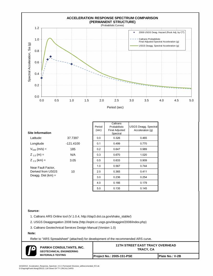
Site InformationLatitude: 37.7397 0.0 0.326 0.465
Longitude -121.4100 0.1 0.499 0.770
VS30 (m/s) = 185 0.2 0.647 0.989
Z 1.0 (m) = N/A 0.3 0.670 1.020
Z 2.5 (km) = 3.05 0.5 0.633 0.909
1.0 0.567 0.744
10 2.0 0.365 0.411
3.0 0.236 0.254
4.0 0.166 0.179
5.0 0.135 0.145
Source:
1. Caltrans ARS Online tool (V.1.0.4, http://dap3.dot.ca.gov/shake_stable/)
2. USGS Deaggregation 2008 beta (http://eqint.cr.usgs.gov/deaggint/2008/index.php)
3. Caltrans Geotechnical Services Design Manual (Version 1.0)
Note:
Refer to "ARS Spreadsheet" (attached) for development of the recommended ARS curve.
PARIKH CONSULTANTS, INC.GEOTECHNICAL ENGINEERINGMATERIALS TESTING Project No.: 2005-151-PSE Plate No.: V-2B
11TH STREET EAST TRACY OVERHEAD TRACY, CA
USGS Deagg. Spectral Acceleration (g)
Caltrans Probabilistic
Final Adjusted Spectral
Near Fault Factor, Derived from USGS Deagg. Dist (km) =
Period (sec)
0.0
0.2
0.4
0.6
0.8
1.0
1.2
0.0 0.5 1.0 1.5 2.0 2.5 3.0 3.5 4.0 4.5 5.0
Spe
ctra
l Acc
eler
atio
n, S
a (g
)
Period (sec)
ACCELERATION RESPONSE SPECTRUM COMPARISON(PERMANENT STRUCTURE)
(Probablistic Curves)
2008 USGS Deag. Hazard (Rock Adj. by CT)
Caltrans ProbabilisticFinal Adjusted Spectral Acceleration (g)
USGS Deagg. Spectral Acceleration (g)
10/18/2012 Acceleration_Response_Spectrum_V1.0_Permanent Structure_withrecomended_EO.xlsS:\Ongoing\Frank Wang\205151 11th Street OH TY LIN\CALC\ARS\
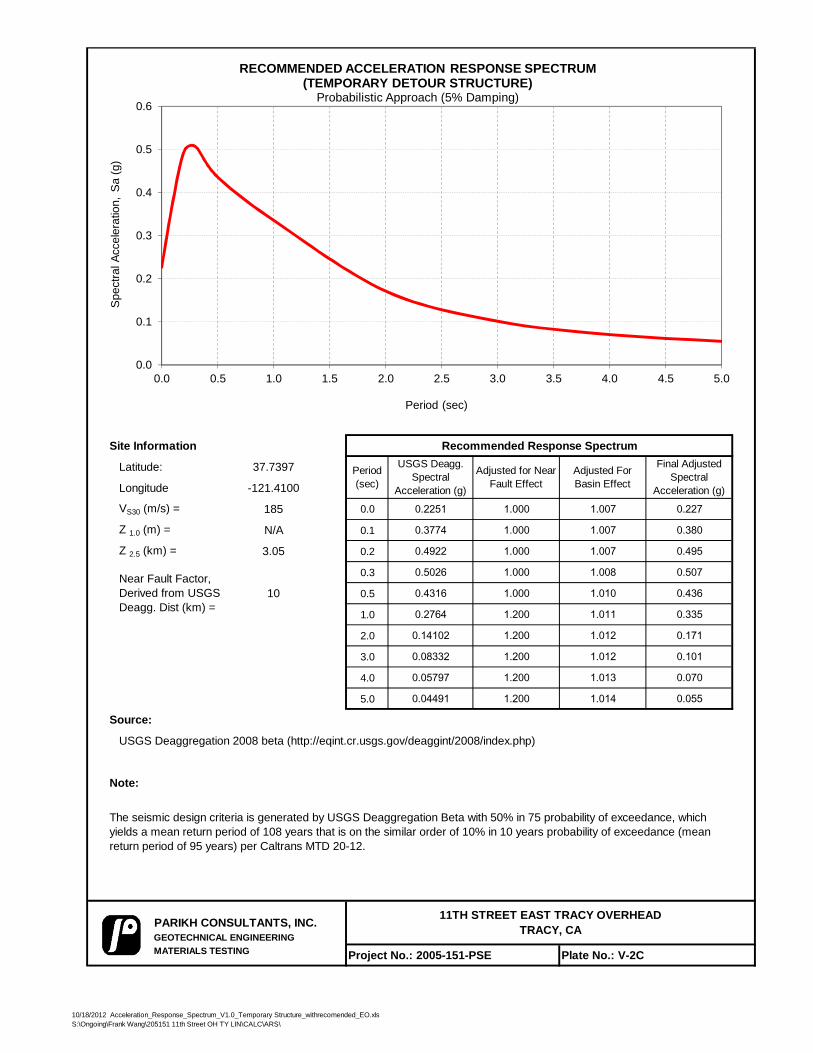
Site Information Recommended Response Spectrum
Latitude: 37.7397
Longitude -121.4100
VS30 (m/s) = 185 0.0 0.2251 1.000 1.007 0.227
Z 1.0 (m) = N/A 0.1 0.3774 1.000 1.007 0.380
Z 2.5 (km) = 3.05 0.2 0.4922 1.000 1.007 0.495
0.3 0.5026 1.000 1.008 0.507
10 0.5 0.4316 1.000 1.010 0.436
1.0 0.2764 1.200 1.011 0.335
2.0 0.14102 1.200 1.012 0.171
3.0 0.08332 1.200 1.012 0.101
4.0 0.05797 1.200 1.013 0.070
5.0 0.04491 1.200 1.014 0.055
Source:
USGS Deaggregation 2008 beta (http://eqint.cr.usgs.gov/deaggint/2008/index.php)
Note:
PARIKH CONSULTANTS, INC.GEOTECHNICAL ENGINEERINGMATERIALS TESTING Project No.: 2005-151-PSE Plate No.: V-2C
The seismic design criteria is generated by USGS Deaggregation Beta with 50% in 75 probability of exceedance, which yields a mean return period of 108 years that is on the similar order of 10% in 10 years probability of exceedance (mean return period of 95 years) per Caltrans MTD 20-12.
Period (sec)
USGS Deagg. Spectral
Acceleration (g)
Adjusted for Near Fault Effect
Adjusted For Basin Effect
Final Adjusted Spectral
Acceleration (g)
Near Fault Factor, Derived from USGS Deagg. Dist (km) =
11TH STREET EAST TRACY OVERHEAD TRACY, CA
0.0
0.1
0.2
0.3
0.4
0.5
0.6
0.0 0.5 1.0 1.5 2.0 2.5 3.0 3.5 4.0 4.5 5.0
Spe
ctra
l Acc
eler
atio
n, S
a (g
)
Period (sec)
RECOMMENDED ACCELERATION RESPONSE SPECTRUM(TEMPORARY DETOUR STRUCTURE)
Probabilistic Approach (5% Damping)
10/18/2012 Acceleration_Response_Spectrum_V1.0_Temporary Structure_withrecomended_EO.xlsS:\Ongoing\Frank Wang\205151 11th Street OH TY LIN\CALC\ARS\
LIQUEFACTION ANALYSIS RESULTS
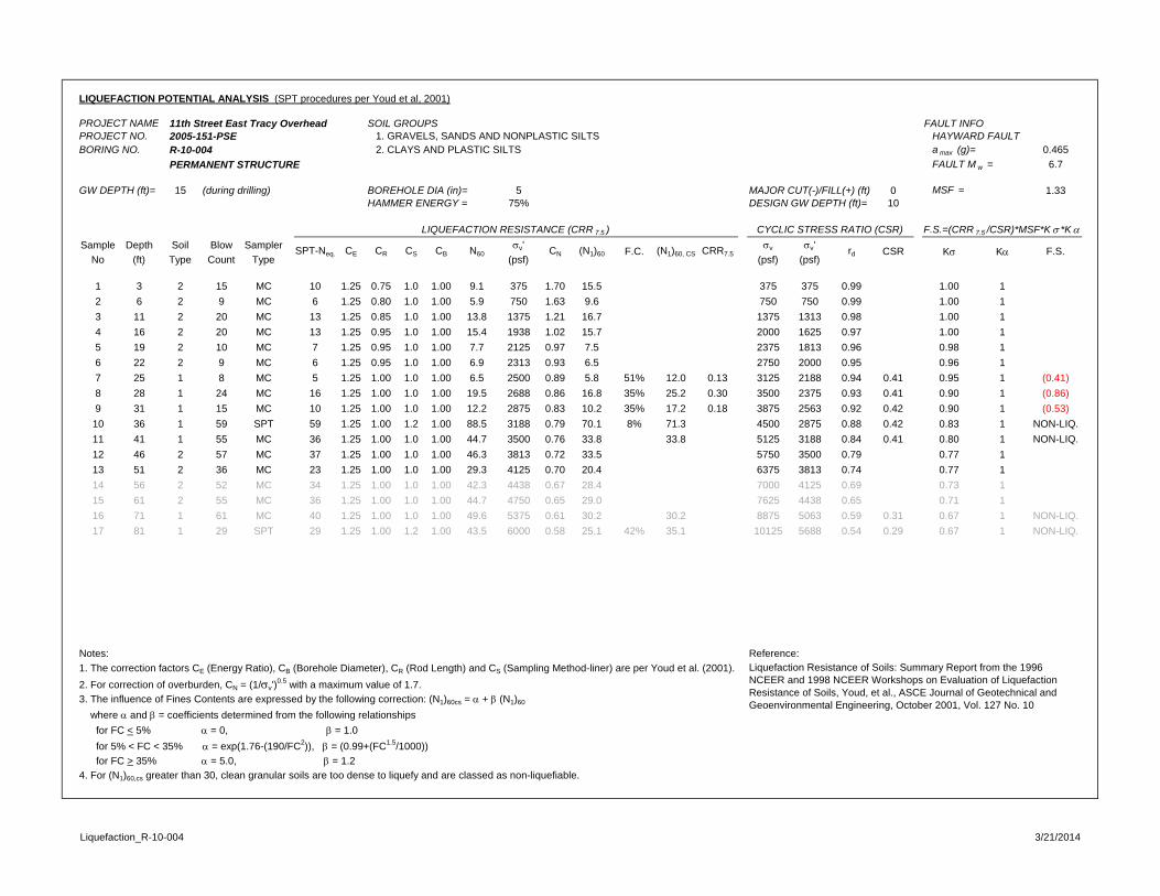
LIQUEFACTION POTENTIAL ANALYSIS (SPT procedures per Youd et al, 2001)
PROJECT NAME 11th Street East Tracy Overhead SOIL GROUPS FAULT INFOPROJECT NO. 2005-151-PSE 1. GRAVELS, SANDS AND NONPLASTIC SILTS HAYWARD FAULTBORING NO. R-10-004 2. CLAYS AND PLASTIC SILTS a max (g)= 0.465
PERMANENT STRUCTURE FAULT M w = 6.7
GW DEPTH (ft)= 15 (during drilling) BOREHOLE DIA (in)= 5 MAJOR CUT(-)/FILL(+) (ft) 0 MSF = 1.33HAMMER ENERGY = 75% DESIGN GW DEPTH (ft)= 10
Sample Depth Soil Blow Sampler v' v v'No (ft) Type Count Type (psf) (psf) (psf)
1 3 2 15 MC 10 1.25 0.75 1.0 1.00 9.1 375 1.70 15.5 375 375 0.99 1.00 12 6 2 9 MC 6 1.25 0.80 1.0 1.00 5.9 750 1.63 9.6 750 750 0.99 1.00 13 11 2 20 MC 13 1.25 0.85 1.0 1.00 13.8 1375 1.21 16.7 1375 1313 0.98 1.00 14 16 2 20 MC 13 1.25 0.95 1.0 1.00 15.4 1938 1.02 15.7 2000 1625 0.97 1.00 15 19 2 10 MC 7 1.25 0.95 1.0 1.00 7.7 2125 0.97 7.5 2375 1813 0.96 0.98 16 22 2 9 MC 6 1.25 0.95 1.0 1.00 6.9 2313 0.93 6.5 2750 2000 0.95 0.96 17 25 1 8 MC 5 1.25 1.00 1.0 1.00 6.5 2500 0.89 5.8 51% 12.0 0.13 3125 2188 0.94 0.41 0.95 1 (0.41)8 28 1 24 MC 16 1.25 1.00 1.0 1.00 19.5 2688 0.86 16.8 35% 25.2 0.30 3500 2375 0.93 0.41 0.90 1 (0.86)9 31 1 15 MC 10 1.25 1.00 1.0 1.00 12.2 2875 0.83 10.2 35% 17.2 0.18 3875 2563 0.92 0.42 0.90 1 (0.53)10 36 1 59 SPT 59 1.25 1.00 1.2 1.00 88.5 3188 0.79 70.1 8% 71.3 4500 2875 0.88 0.42 0.83 1 NON-LIQ.11 41 1 55 MC 36 1.25 1.00 1.0 1.00 44.7 3500 0.76 33.8 33.8 5125 3188 0.84 0.41 0.80 1 NON-LIQ.12 46 2 57 MC 37 1.25 1.00 1.0 1.00 46.3 3813 0.72 33.5 5750 3500 0.79 0.77 113 51 2 36 MC 23 1.25 1.00 1.0 1.00 29.3 4125 0.70 20.4 6375 3813 0.74 0.77 114 56 2 52 MC 34 1.25 1.00 1.0 1.00 42.3 4438 0.67 28.4 7000 4125 0.69 0.73 115 61 2 55 MC 36 1.25 1.00 1.0 1.00 44.7 4750 0.65 29.0 7625 4438 0.65 0.71 116 71 1 61 MC 40 1.25 1.00 1.0 1.00 49.6 5375 0.61 30.2 30.2 8875 5063 0.59 0.31 0.67 1 NON-LIQ.17 81 1 29 SPT 29 1.25 1.00 1.2 1.00 43.5 6000 0.58 25.1 42% 35.1 10125 5688 0.54 0.29 0.67 1 NON-LIQ.
Notes: Reference: 1. The correction factors CE (Energy Ratio), CB (Borehole Diameter), CR (Rod Length) and CS (Sampling Method-liner) are per Youd et al. (2001).2. For correction of overburden, CN = (1/v')
0.5 with a maximum value of 1.7. 3. The influence of Fines Contents are expressed by the following correction: (N1)60cs = + (N1)60
where and = coefficients determined from the following relationships for FC < 5% = 0, = 1.0 for 5% < FC < 35% = exp(1.76-(190/FC2)), = (0.99+(FC1.5/1000)) for FC > 35% = 5.0, = 1.24. For (N1)60,cs greater than 30, clean granular soils are too dense to liquefy and are classed as non-liquefiable.
Liquefaction Resistance of Soils: Summary Report from the 1996 NCEER and 1998 NCEER Workshops on Evaluation of Liquefaction Resistance of Soils, Youd, et al., ASCE Journal of Geotechnical and Geoenvironmental Engineering, October 2001, Vol. 127 No. 10
K K F.S.CSR
LIQUEFACTION RESISTANCE (CRR 7.5 ) CYCLIC STRESS RATIO (CSR) F.S.=(CRR 7.5 /CSR)*MSF*K *K
SPT-Neq. CE CR CS CB N60 CN (N1)60 F.C. (N1)60, CS CRR7.5 rd
Liquefaction_R-10-004 3/21/2014
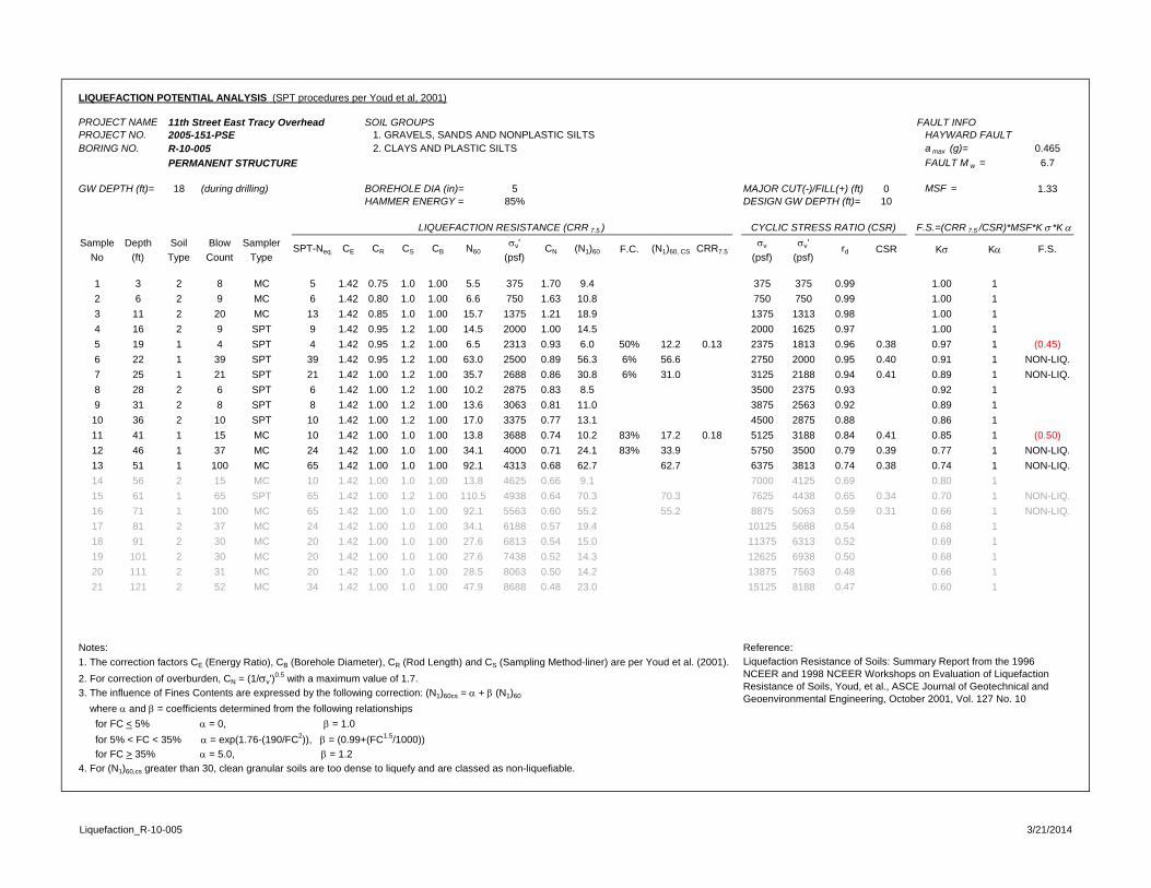
LIQUEFACTION POTENTIAL ANALYSIS (SPT procedures per Youd et al, 2001)
PROJECT NAME 11th Street East Tracy Overhead SOIL GROUPS FAULT INFOPROJECT NO. 2005-151-PSE 1. GRAVELS, SANDS AND NONPLASTIC SILTS HAYWARD FAULTBORING NO. R-10-005 2. CLAYS AND PLASTIC SILTS a max (g)= 0.465
PERMANENT STRUCTURE FAULT M w = 6.7
GW DEPTH (ft)= 18 (during drilling) BOREHOLE DIA (in)= 5 MAJOR CUT(-)/FILL(+) (ft) 0 MSF = 1.33HAMMER ENERGY = 85% DESIGN GW DEPTH (ft)= 10
Sample Depth Soil Blow Sampler v' v v'No (ft) Type Count Type (psf) (psf) (psf)
1 3 2 8 MC 5 1.42 0.75 1.0 1.00 5.5 375 1.70 9.4 375 375 0.99 1.00 12 6 2 9 MC 6 1.42 0.80 1.0 1.00 6.6 750 1.63 10.8 750 750 0.99 1.00 13 11 2 20 MC 13 1.42 0.85 1.0 1.00 15.7 1375 1.21 18.9 1375 1313 0.98 1.00 14 16 2 9 SPT 9 1.42 0.95 1.2 1.00 14.5 2000 1.00 14.5 2000 1625 0.97 1.00 15 19 1 4 SPT 4 1.42 0.95 1.2 1.00 6.5 2313 0.93 6.0 50% 12.2 0.13 2375 1813 0.96 0.38 0.97 1 (0.45)6 22 1 39 SPT 39 1.42 0.95 1.2 1.00 63.0 2500 0.89 56.3 6% 56.6 2750 2000 0.95 0.40 0.91 1 NON-LIQ.7 25 1 21 SPT 21 1.42 1.00 1.2 1.00 35.7 2688 0.86 30.8 6% 31.0 3125 2188 0.94 0.41 0.89 1 NON-LIQ.8 28 2 6 SPT 6 1.42 1.00 1.2 1.00 10.2 2875 0.83 8.5 3500 2375 0.93 0.92 19 31 2 8 SPT 8 1.42 1.00 1.2 1.00 13.6 3063 0.81 11.0 3875 2563 0.92 0.89 110 36 2 10 SPT 10 1.42 1.00 1.2 1.00 17.0 3375 0.77 13.1 4500 2875 0.88 0.86 111 41 1 15 MC 10 1.42 1.00 1.0 1.00 13.8 3688 0.74 10.2 83% 17.2 0.18 5125 3188 0.84 0.41 0.85 1 (0.50)12 46 1 37 MC 24 1.42 1.00 1.0 1.00 34.1 4000 0.71 24.1 83% 33.9 5750 3500 0.79 0.39 0.77 1 NON-LIQ.13 51 1 100 MC 65 1.42 1.00 1.0 1.00 92.1 4313 0.68 62.7 62.7 6375 3813 0.74 0.38 0.74 1 NON-LIQ.14 56 2 15 MC 10 1.42 1.00 1.0 1.00 13.8 4625 0.66 9.1 7000 4125 0.69 0.80 115 61 1 65 SPT 65 1.42 1.00 1.2 1.00 110.5 4938 0.64 70.3 70.3 7625 4438 0.65 0.34 0.70 1 NON-LIQ.16 71 1 100 MC 65 1.42 1.00 1.0 1.00 92.1 5563 0.60 55.2 55.2 8875 5063 0.59 0.31 0.66 1 NON-LIQ.17 81 2 37 MC 24 1.42 1.00 1.0 1.00 34.1 6188 0.57 19.4 10125 5688 0.54 0.68 118 91 2 30 MC 20 1.42 1.00 1.0 1.00 27.6 6813 0.54 15.0 11375 6313 0.52 0.69 119 101 2 30 MC 20 1.42 1.00 1.0 1.00 27.6 7438 0.52 14.3 12625 6938 0.50 0.68 120 111 2 31 MC 20 1.42 1.00 1.0 1.00 28.5 8063 0.50 14.2 13875 7563 0.48 0.66 121 121 2 52 MC 34 1.42 1.00 1.0 1.00 47.9 8688 0.48 23.0 15125 8188 0.47 0.60 1
Notes: Reference: 1. The correction factors CE (Energy Ratio), CB (Borehole Diameter), CR (Rod Length) and CS (Sampling Method-liner) are per Youd et al. (2001).2. For correction of overburden, CN = (1/v')
0.5 with a maximum value of 1.7. 3. The influence of Fines Contents are expressed by the following correction: (N1)60cs = + (N1)60
where and = coefficients determined from the following relationships for FC < 5% = 0, = 1.0 for 5% < FC < 35% = exp(1.76-(190/FC2)), = (0.99+(FC1.5/1000)) for FC > 35% = 5.0, = 1.24. For (N1)60,cs greater than 30, clean granular soils are too dense to liquefy and are classed as non-liquefiable.
Liquefaction Resistance of Soils: Summary Report from the 1996 NCEER and 1998 NCEER Workshops on Evaluation of Liquefaction Resistance of Soils, Youd, et al., ASCE Journal of Geotechnical and Geoenvironmental Engineering, October 2001, Vol. 127 No. 10
K K F.S.CSR
LIQUEFACTION RESISTANCE (CRR 7.5 ) CYCLIC STRESS RATIO (CSR) F.S.=(CRR 7.5 /CSR)*MSF*K *K
SPT-Neq. CE CR CS CB N60 CN (N1)60 F.C. (N1)60, CS CRR7.5 rd
Liquefaction_R-10-005 3/21/2014
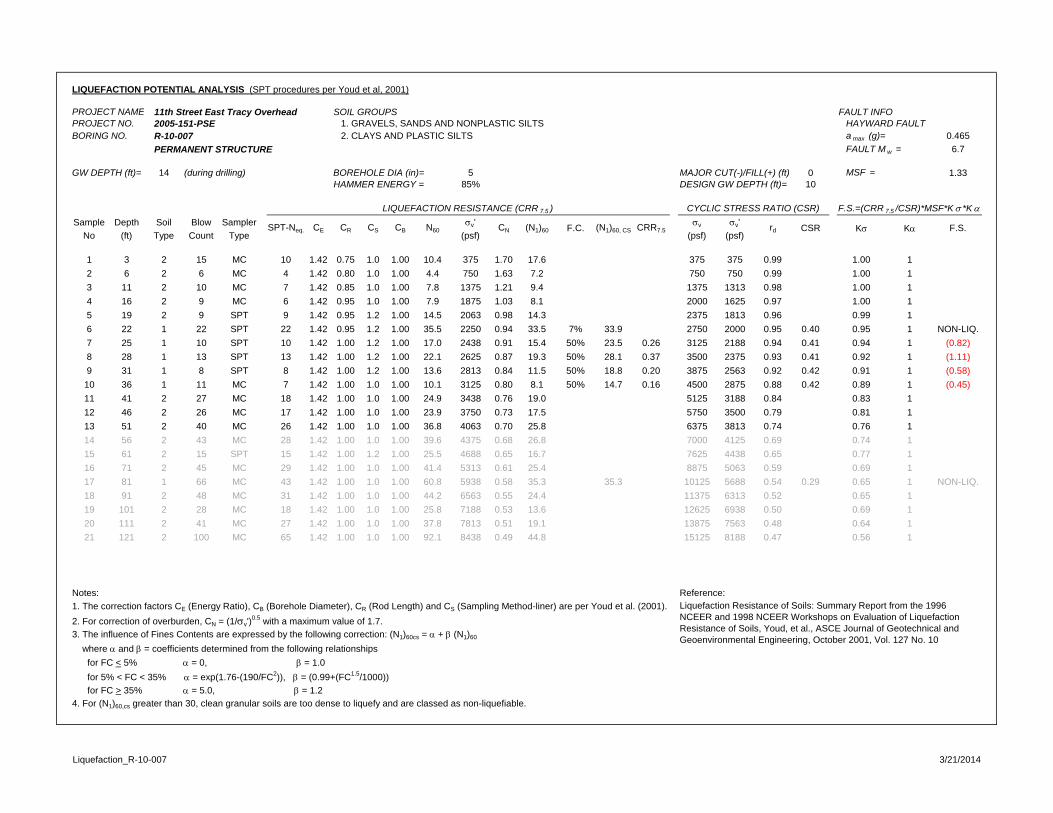
LIQUEFACTION POTENTIAL ANALYSIS (SPT procedures per Youd et al, 2001)
PROJECT NAME 11th Street East Tracy Overhead SOIL GROUPS FAULT INFOPROJECT NO. 2005-151-PSE 1. GRAVELS, SANDS AND NONPLASTIC SILTS HAYWARD FAULTBORING NO. R-10-007 2. CLAYS AND PLASTIC SILTS a max (g)= 0.465
PERMANENT STRUCTURE FAULT M w = 6.7
GW DEPTH (ft)= 14 (during drilling) BOREHOLE DIA (in)= 5 MAJOR CUT(-)/FILL(+) (ft) 0 MSF = 1.33HAMMER ENERGY = 85% DESIGN GW DEPTH (ft)= 10
Sample Depth Soil Blow Sampler v' v v'No (ft) Type Count Type (psf) (psf) (psf)
1 3 2 15 MC 10 1.42 0.75 1.0 1.00 10.4 375 1.70 17.6 375 375 0.99 1.00 12 6 2 6 MC 4 1.42 0.80 1.0 1.00 4.4 750 1.63 7.2 750 750 0.99 1.00 13 11 2 10 MC 7 1.42 0.85 1.0 1.00 7.8 1375 1.21 9.4 1375 1313 0.98 1.00 14 16 2 9 MC 6 1.42 0.95 1.0 1.00 7.9 1875 1.03 8.1 2000 1625 0.97 1.00 15 19 2 9 SPT 9 1.42 0.95 1.2 1.00 14.5 2063 0.98 14.3 2375 1813 0.96 0.99 16 22 1 22 SPT 22 1.42 0.95 1.2 1.00 35.5 2250 0.94 33.5 7% 33.9 2750 2000 0.95 0.40 0.95 1 NON-LIQ.7 25 1 10 SPT 10 1.42 1.00 1.2 1.00 17.0 2438 0.91 15.4 50% 23.5 0.26 3125 2188 0.94 0.41 0.94 1 (0.82)8 28 1 13 SPT 13 1.42 1.00 1.2 1.00 22.1 2625 0.87 19.3 50% 28.1 0.37 3500 2375 0.93 0.41 0.92 1 (1.11)9 31 1 8 SPT 8 1.42 1.00 1.2 1.00 13.6 2813 0.84 11.5 50% 18.8 0.20 3875 2563 0.92 0.42 0.91 1 (0.58)10 36 1 11 MC 7 1.42 1.00 1.0 1.00 10.1 3125 0.80 8.1 50% 14.7 0.16 4500 2875 0.88 0.42 0.89 1 (0.45)11 41 2 27 MC 18 1.42 1.00 1.0 1.00 24.9 3438 0.76 19.0 5125 3188 0.84 0.83 112 46 2 26 MC 17 1.42 1.00 1.0 1.00 23.9 3750 0.73 17.5 5750 3500 0.79 0.81 113 51 2 40 MC 26 1.42 1.00 1.0 1.00 36.8 4063 0.70 25.8 6375 3813 0.74 0.76 114 56 2 43 MC 28 1.42 1.00 1.0 1.00 39.6 4375 0.68 26.8 7000 4125 0.69 0.74 115 61 2 15 SPT 15 1.42 1.00 1.2 1.00 25.5 4688 0.65 16.7 7625 4438 0.65 0.77 116 71 2 45 MC 29 1.42 1.00 1.0 1.00 41.4 5313 0.61 25.4 8875 5063 0.59 0.69 117 81 1 66 MC 43 1.42 1.00 1.0 1.00 60.8 5938 0.58 35.3 35.3 10125 5688 0.54 0.29 0.65 1 NON-LIQ.18 91 2 48 MC 31 1.42 1.00 1.0 1.00 44.2 6563 0.55 24.4 11375 6313 0.52 0.65 119 101 2 28 MC 18 1.42 1.00 1.0 1.00 25.8 7188 0.53 13.6 12625 6938 0.50 0.69 120 111 2 41 MC 27 1.42 1.00 1.0 1.00 37.8 7813 0.51 19.1 13875 7563 0.48 0.64 121 121 2 100 MC 65 1.42 1.00 1.0 1.00 92.1 8438 0.49 44.8 15125 8188 0.47 0.56 1
Notes: Reference: 1. The correction factors CE (Energy Ratio), CB (Borehole Diameter), CR (Rod Length) and CS (Sampling Method-liner) are per Youd et al. (2001).2. For correction of overburden, CN = (1/v')
0.5 with a maximum value of 1.7. 3. The influence of Fines Contents are expressed by the following correction: (N1)60cs = + (N1)60
where and = coefficients determined from the following relationships for FC < 5% = 0, = 1.0 for 5% < FC < 35% = exp(1.76-(190/FC2)), = (0.99+(FC1.5/1000)) for FC > 35% = 5.0, = 1.24. For (N1)60,cs greater than 30, clean granular soils are too dense to liquefy and are classed as non-liquefiable.
Liquefaction Resistance of Soils: Summary Report from the 1996 NCEER and 1998 NCEER Workshops on Evaluation of Liquefaction Resistance of Soils, Youd, et al., ASCE Journal of Geotechnical and Geoenvironmental Engineering, October 2001, Vol. 127 No. 10
K K F.S.CSR
LIQUEFACTION RESISTANCE (CRR 7.5 ) CYCLIC STRESS RATIO (CSR) F.S.=(CRR 7.5 /CSR)*MSF*K *K
SPT-Neq. CE CR CS CB N60 CN (N1)60 F.C. (N1)60, CS CRR7.5 rd
Liquefaction_R-10-007 3/21/2014
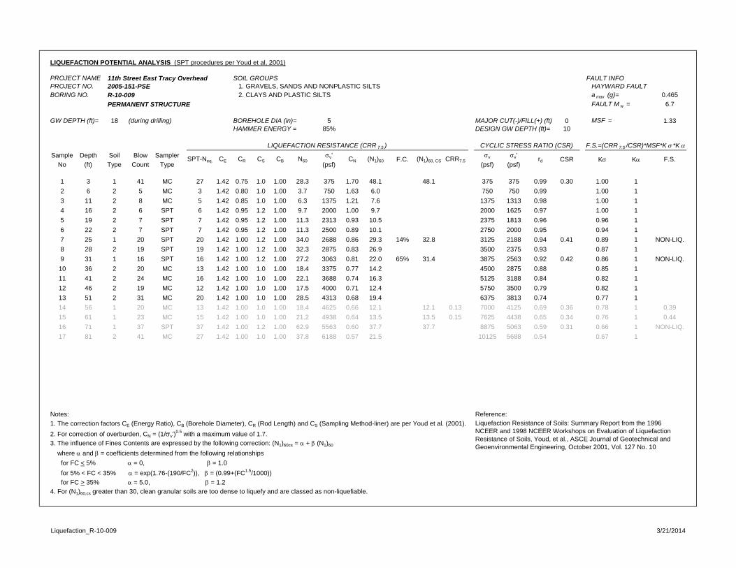
LIQUEFACTION POTENTIAL ANALYSIS (SPT procedures per Youd et al, 2001)
PROJECT NAME 11th Street East Tracy Overhead SOIL GROUPS FAULT INFOPROJECT NO. 2005-151-PSE 1. GRAVELS, SANDS AND NONPLASTIC SILTS HAYWARD FAULTBORING NO. R-10-009 2. CLAYS AND PLASTIC SILTS a max (g)= 0.465
PERMANENT STRUCTURE FAULT M w = 6.7
GW DEPTH (ft)= 18 (during drilling) BOREHOLE DIA (in)= 5 MAJOR CUT(-)/FILL(+) (ft) 0 MSF = 1.33HAMMER ENERGY = 85% DESIGN GW DEPTH (ft)= 10
Sample Depth Soil Blow Sampler v' v v'No (ft) Type Count Type (psf) (psf) (psf)
1 3 1 41 MC 27 1.42 0.75 1.0 1.00 28.3 375 1.70 48.1 48.1 375 375 0.99 0.30 1.00 12 6 2 5 MC 3 1.42 0.80 1.0 1.00 3.7 750 1.63 6.0 750 750 0.99 1.00 13 11 2 8 MC 5 1.42 0.85 1.0 1.00 6.3 1375 1.21 7.6 1375 1313 0.98 1.00 14 16 2 6 SPT 6 1.42 0.95 1.2 1.00 9.7 2000 1.00 9.7 2000 1625 0.97 1.00 15 19 2 7 SPT 7 1.42 0.95 1.2 1.00 11.3 2313 0.93 10.5 2375 1813 0.96 0.96 16 22 2 7 SPT 7 1.42 0.95 1.2 1.00 11.3 2500 0.89 10.1 2750 2000 0.95 0.94 17 25 1 20 SPT 20 1.42 1.00 1.2 1.00 34.0 2688 0.86 29.3 14% 32.8 3125 2188 0.94 0.41 0.89 1 NON-LIQ.8 28 2 19 SPT 19 1.42 1.00 1.2 1.00 32.3 2875 0.83 26.9 3500 2375 0.93 0.87 19 31 1 16 SPT 16 1.42 1.00 1.2 1.00 27.2 3063 0.81 22.0 65% 31.4 3875 2563 0.92 0.42 0.86 1 NON-LIQ.10 36 2 20 MC 13 1.42 1.00 1.0 1.00 18.4 3375 0.77 14.2 4500 2875 0.88 0.85 111 41 2 24 MC 16 1.42 1.00 1.0 1.00 22.1 3688 0.74 16.3 5125 3188 0.84 0.82 112 46 2 19 MC 12 1.42 1.00 1.0 1.00 17.5 4000 0.71 12.4 5750 3500 0.79 0.82 113 51 2 31 MC 20 1.42 1.00 1.0 1.00 28.5 4313 0.68 19.4 6375 3813 0.74 0.77 114 56 1 20 MC 13 1.42 1.00 1.0 1.00 18.4 4625 0.66 12.1 12.1 0.13 7000 4125 0.69 0.36 0.78 1 0.3915 61 1 23 MC 15 1.42 1.00 1.0 1.00 21.2 4938 0.64 13.5 13.5 0.15 7625 4438 0.65 0.34 0.76 1 0.4416 71 1 37 SPT 37 1.42 1.00 1.2 1.00 62.9 5563 0.60 37.7 37.7 8875 5063 0.59 0.31 0.66 1 NON-LIQ.17 81 2 41 MC 27 1.42 1.00 1.0 1.00 37.8 6188 0.57 21.5 10125 5688 0.54 0.67 1
Notes: Reference: 1. The correction factors CE (Energy Ratio), CB (Borehole Diameter), CR (Rod Length) and CS (Sampling Method-liner) are per Youd et al. (2001).2. For correction of overburden, CN = (1/v')
0.5 with a maximum value of 1.7. 3. The influence of Fines Contents are expressed by the following correction: (N1)60cs = + (N1)60
where and = coefficients determined from the following relationships for FC < 5% = 0, = 1.0 for 5% < FC < 35% = exp(1.76-(190/FC2)), = (0.99+(FC1.5/1000)) for FC > 35% = 5.0, = 1.24. For (N1)60,cs greater than 30, clean granular soils are too dense to liquefy and are classed as non-liquefiable.
LIQUEFACTION RESISTANCE (CRR 7.5 ) CYCLIC STRESS RATIO (CSR) F.S.=(CRR 7.5 /CSR)*MSF*K *K
SPT-Neq. CE CR CS CB N60 CN (N1)60 F.C. (N1)60, CS CRR7.5 rd
Liquefaction Resistance of Soils: Summary Report from the 1996 NCEER and 1998 NCEER Workshops on Evaluation of Liquefaction Resistance of Soils, Youd, et al., ASCE Journal of Geotechnical and Geoenvironmental Engineering, October 2001, Vol. 127 No. 10
K K F.S.CSR
Liquefaction_R-10-009 3/21/2014
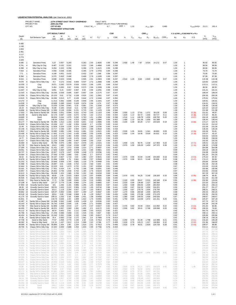
LIQUEFACTION POTENTIAL ANALYSIS (per Youd et al., 2001)
PROJECT NAME 11TH STREET EAST TRACY OVERHEAD FAULT INFOPROJECT NO. 2005-151-PSE GREAT VALLEY FAULT (REVERSE)CPT NO. CPT-07-001 FAULT M w = 6.7 MSF = 1.33 a max (g)= 0.465 VS30m(m/s)= 211.5 181.4
PERMANENT STRUCTURE
Depth qc fs v u v'(ft) (tsf) (tsf) (tsf) (tsf) (tsf)
0.4921.1481.8042.4613.1173.7734.4295.085 1 Sensitive Fines 5.37 0.057 0.283 0.283 2.55 1.4835 0.99 0.299 2.550 1.48 7.97 3.034 24.172 0.07 1.00 1 95.92 95.925.741 4 Silty Clay to Clay 6.467 0.132 0.321 0.321 2.68 1.4464 0.99 0.299 1.00 1 98.56 98.566.398 4 Silty Clay to Clay 5.264 0.102 0.358 0.358 2.79 1.4121 0.99 0.298 1.00 1 86.66 86.667.054 1 Sensitive Fines 4.059 0.038 0.395 0.395 2.79 1.3793 0.99 0.298 1.00 1 73.70 73.707.71 1 Sensitive Fines 4.189 0.051 0.432 0.432 2.87 1.348 0.98 0.297 1.00 1 75.05 75.058.366 1 Sensitive Fines 5.375 0.063 0.468 0.468 2.78 1.3189 0.98 0.297 1.00 1 87.99 87.999.022 1 Sensitive Fines 6.698 0.023 0.505 0.505 2.51 1.2903 0.98 0.297 2.510 1.29 8.64 2.820 24.368 0.07 1.00 1 115.38 115.389.678 5 Clayey Silt to Silty Clay 9.3 0.172 0.542 0.005 0.537 2.72 1.2666 0.98 0.299 1.00 1 123.82 123.8210.335 3 Clay 8.071 0.292 0.579 0.026 0.553 2.96 1.255 0.98 0.310 1.00 1 113.11 113.1110.991 9 Sand 5.464 0.093 0.62 0.046 0.573 2.96 1.2408 0.98 0.320 1.00 1 88.50 88.5011.647 4 Silty Clay to Clay 6.851 0.15 0.657 0.067 0.59 2.94 1.2291 0.98 0.328 1.00 1 101.21 101.2112.303 5 Clayey Silt to Silty Clay 18.265 0.538 0.695 0.087 0.607 2.64 1.2175 0.97 0.337 1.00 1 188.04 188.0412.959 5 Clayey Silt to Silty Clay 20.153 0.61 0.732 0.108 0.624 2.62 1.2061 0.97 0.345 1.00 1 200.36 200.3613.615 5 Clayey Silt to Silty Clay 16.382 0.513 0.77 0.128 0.642 2.72 1.1944 0.97 0.352 1.00 1 175.91 175.9114.272 3 Clay 11.514 0.482 0.806 0.149 0.658 2.94 1.1841 0.97 0.359 1.00 1 140.81 140.8114.928 3 Clay 10.689 0.389 0.843 0.169 0.674 2.94 1.174 0.97 0.366 1.00 1 134.31 134.3115.584 4 Silty Clay to Clay 10.205 0.294 0.881 0.19 0.691 2.91 1.1634 0.97 0.373 1.00 1 130.46 130.4616.24 5 Clayey Silt to Silty Clay 9.168 0.183 0.918 0.21 0.708 2.87 1.153 0.97 0.379 1.00 1 122.22 122.2216.896 6 Sandy Silt to Clayey Silt 12.995 0.149 0.956 0.231 0.725 2.61 1.1429 0.96 0.384 1.00 1 151.98 151.9817.552 7 Silty Sand to Sandy Silt 24.565 0.051 0.994 0.251 0.743 2.05 1.1323 0.96 0.389 2.050 1.13 27.81 1.371 38.135 0.08 1.00 1 (0.28) 151.61 48.9718.209 8 Sand to Silty Sand 62.175 0.097 1.034 0.272 0.762 1.62 1.1213 0.96 0.394 1.620 1.12 69.72 1.000 69.717 0.11 1.00 1 (0.38) 172.32 96.2618.865 9 Sand 98.052 0.244 1.075 0.292 0.783 1.51 1.1094 0.96 0.398 1.510 1.11 108.78 1.000 108.782 0.20 1.00 1 (0.67) 184.18 149.8919.521 9 Sand 146.94 0.633 1.116 0.313 0.803 1.48 1.0984 0.96 0.402 1.480 1.10 161.39 1.000 161.388 1.00 1 195.44 195.4420.177 7 Silty Sand to Sandy Silt 55.385 1.012 1.154 0.333 0.821 2.22 1.0886 0.96 0.406 2.220 1.09 60.29 1.717 103.529 0.18 1.00 1 (0.60) 173.17 103.7620.833 5 Clayey Silt to Silty Clay 22.036 0.67 1.192 0.354 0.838 2.7 1.0795 0.95 0.410 1.00 1 212.24 212.2421.49 5 Clayey Silt to Silty Clay 12.839 0.329 1.229 0.374 0.855 2.88 1.0706 0.95 0.414 1.00 1 151.09 151.0922.146 5 Clayey Silt to Silty Clay 10.717 0.196 1.267 0.394 0.872 2.88 1.0618 0.95 0.418 1.00 1 135.26 135.2622.802 7 Silty Sand to Sandy Silt 33.082 0.085 1.306 0.415 0.891 2.03 1.0521 0.95 0.420 2.030 1.05 34.81 1.341 46.683 0.09 1.00 1 (0.28) 165.56 55.8123.458 6 Sandy Silt to Clayey Silt 17.691 0.175 1.343 0.435 0.908 2.55 1.0436 0.95 0.423 2.550 1.04 18.46 3.034 56.021 0.10 1.00 1 (0.30) 153.37 45.1424.114 5 Clayey Silt to Silty Clay 11.319 0.164 1.381 0.456 0.925 2.81 1.0353 0.94 0.426 1.00 1 143.04 143.0424.77 5 Clayey Silt to Silty Clay 13.319 0.328 1.418 0.476 0.942 2.87 1.0271 0.94 0.429 1.00 1 158.90 158.9025.427 5 Clayey Silt to Silty Clay 11.224 0.248 1.456 0.497 0.959 2.93 1.019 0.94 0.431 1.00 1 142.35 142.3526.083 8 Sand to Silty Sand 95.796 0.975 1.496 0.517 0.978 1.93 1.0101 0.94 0.434 1.930 1.01 96.76 1.218 117.903 0.23 1.00 1 (0.72) 195.01 151.6226.739 7 Silty Sand to Sandy Silt 104.9 1.836 1.534 0.538 0.997 2.07 1.0014 0.94 0.435 2.070 1.00 105.05 1.403 147.372 0.38 1.00 1 (1.16) 198.30 174.9827.395 5 Clayey Silt to Silty Clay 31.421 1.187 1.572 0.558 1.014 2.71 0.9937 0.93 0.437 1.00 1 264.98 264.9828.051 5 Clayey Silt to Silty Clay 17.635 0.469 1.609 0.579 1.031 2.84 0.9861 0.93 0.439 0.99 1 184.18 184.1828.707 5 Clayey Silt to Silty Clay 22.827 0.579 1.647 0.599 1.048 2.73 0.9786 0.93 0.440 0.99 1 216.98 216.9829.364 5 Clayey Silt to Silty Clay 27.043 0.759 1.685 0.62 1.065 2.7 0.9713 0.92 0.442 0.99 1 241.33 241.3330.02 6 Sandy Silt to Clayey Silt 34.167 0.827 1.722 0.64 1.082 2.57 0.9641 0.92 0.443 2.570 0.96 32.94 3.148 103.692 0.18 0.98 1 (0.54) 175.22 64.3230.676 6 Sandy Silt to Clayey Silt 31.566 0.658 1.76 0.661 1.099 2.57 0.9569 0.92 0.444 2.570 0.96 30.21 3.148 95.090 0.16 0.98 1 (0.47) 174.12 59.5831.332 5 Clayey Silt to Silty Clay 20.649 0.509 1.797 0.681 1.116 2.79 0.9499 0.91 0.445 0.98 1 203.66 203.6631.988 5 Clayey Silt to Silty Clay 28.987 0.81 1.835 0.702 1.133 2.69 0.943 0.91 0.445 0.98 1 252.28 252.2832.644 5 Clayey Silt to Silty Clay 22.225 0.81 1.873 0.722 1.151 2.87 0.9358 0.91 0.446 0.97 1 213.26 213.2633.301 5 Clayey Silt to Silty Clay 17.401 0.434 1.91 0.743 1.168 2.88 0.9291 0.90 0.446 0.97 1 182.86 182.8633.957 5 Clayey Silt to Silty Clay 25.801 0.736 1.948 0.763 1.185 2.76 0.9224 0.90 0.446 0.97 1 234.66 234.6634.613 5 Clayey Silt to Silty Clay 39.459 1.324 1.985 0.783 1.202 2.65 0.9159 0.89 0.446 0.96 1 307.29 307.2935.269 6 Sandy Silt to Clayey Silt 48.65 1.59 2.023 0.804 1.219 2.57 0.9095 0.89 0.446 2.570 0.91 44.25 3.148 139.283 0.33 0.96 1 (0.95) 189.74 86.4535.925 5 Clayey Silt to Silty Clay 40.329 1.413 2.061 0.824 1.236 2.66 0.9031 0.88 0.446 0.96 1 311.59 311.5936.581 7 Silty Sand to Sandy Silt 77.71 1.796 2.099 0.845 1.254 2.32 0.8965 0.88 0.445 2.320 0.90 69.67 2.015 140.348 0.34 0.95 1 (0.96) 202.96 124.9537.238 8 Sand to Silty Sand 157.27 2.779 2.139 0.865 1.274 2.02 0.8892 0.87 0.444 2.020 0.89 139.85 1.327 185.584 0.93 1 223.33 223.3337.894 10 Gravelly Sand to Sand 321 1.266 2.181 0.886 1.295 1.35 0.8818 0.87 0.442 1.350 0.88 283.05 1.000 283.050 0.90 1 246.13 246.1338.55 10 Gravelly Sand to Sand 363.91 1.633 2.222 0.906 1.316 1.35 0.8744 0.86 0.441 1.350 0.87 318.20 1.000 318.201 0.90 1 251.27 251.2739.206 10 Gravelly Sand to Sand 321.5 1.119 2.264 0.927 1.337 1.33 0.8672 0.86 0.439 1.330 0.87 278.79 1.000 278.794 0.89 1 248.31 248.3139.862 10 Gravelly Sand to Sand 329.97 0.892 2.306 0.947 1.359 1.27 0.8597 0.85 0.437 1.270 0.86 283.68 1.000 283.676 0.88 1 250.25 250.2540.518 10 Gravelly Sand to Sand 320.6 0.89 2.348 0.968 1.38 1.29 0.8527 0.85 0.435 1.290 0.85 273.38 1.000 273.378 0.88 1 250.35 250.3541.175 10 Gravelly Sand to Sand 295.01 1.032 2.39 0.988 1.401 1.38 0.8458 0.84 0.433 1.380 0.85 249.53 1.000 249.526 0.87 1 248.67 248.6741.831 9 Sand 134.74 0.636 2.43 1.009 1.422 1.75 0.8391 0.83 0.431 1.750 0.84 113.06 1.072 121.151 0.25 0.91 1 (0.69) 225.47 167.1942.487 6 Sandy Silt to Clayey Silt 24.548 0.562 2.468 1.029 1.439 2.8 0.8336 0.83 0.429 0.93 1 227.70 227.7043.143 6 Sandy Silt to Clayey Silt 26.742 0.505 2.505 1.05 1.456 2.71 0.8283 0.82 0.427 0.93 1 242.39 242.3943.799 7 Silty Sand to Sandy Silt 52.856 1.038 2.544 1.07 1.474 2.47 0.8227 0.82 0.425 2.470 0.82 43.49 2.621 113.992 0.22 0.93 1 (0.63) 201.83 80.8644.455 7 Silty Sand to Sandy Silt 48.221 0.937 2.583 1.091 1.492 2.5 0.8172 0.81 0.423 2.500 0.82 39.41 2.768 109.098 0.20 0.92 1 (0.58) 200.20 74.6345.112 6 Sandy Silt to Clayey Silt 38.54 0.842 2.62 1.111 1.509 2.63 0.8121 0.80 0.421 0.92 1 302.70 302.7045.768 5 Clayey Silt to Silty Clay 21.206 0.588 2.658 1.131 1.526 2.93 0.807 0.80 0.419 0.92 1 209.14 209.1446.424 6 Sandy Silt to Clayey Silt 20.342 0.381 2.696 1.152 1.544 2.85 0.8017 0.79 0.417 0.92 1 205.88 205.8847.08 6 Sandy Silt to Clayey Silt 25.4 0.583 2.733 1.172 1.561 2.8 0.7968 0.78 0.414 0.91 1 238.18 238.1847.736 8 Sand to Silty Sand 77.57 1.058 2.773 1.193 1.58 2.25 0.7914 0.78 0.412 2.250 0.79 61.39 1.798 110.388 0.21 0.91 1 (0.61) 216.44 106.2848.392 8 Sand to Silty Sand 131.31 1.437 2.812 1.213 1.599 2.02 0.786 0.77 0.409 2.020 0.79 103.21 1.327 136.955 0.32 0.89 1 (0.92) 231.96 168.9249.049 6 Sandy Silt to Clayey Silt 58.894 1.354 2.85 1.234 1.616 2.51 0.7813 0.76 0.406 2.510 0.78 46.01 2.820 129.728 0.28 0.91 1 (0.84) 209.57 88.8849.705 5 Clayey Silt to Silty Clay 22.342 0.593 2.888 1.254 1.633 2.94 0.7766 0.76 0.404 0.91 1 214.11 214.1150.361 6 Sandy Silt to Clayey Silt 31.694 0.684 2.925 1.275 1.65 2.72 0.7719 0.75 0.401 0.90 1 271.98 271.9851.017 6 Sandy Silt to Clayey Silt 36.062 1.033 2.963 1.295 1.668 2.74 0.7671 0.74 0.399 0.90 1 297.73 297.7351.673 6 Sandy Silt to Clayey Silt 35.894 1.069 3 1.316 1.685 2.75 0.7626 0.74 0.396 0.90 1 298.32 298.3252.329 6 Sandy Silt to Clayey Silt 31.695 0.82 3.038 1.336 1.702 2.75 0.7581 0.73 0.393 0.90 1 279.13 279.1352.986 6 Sandy Silt to Clayey Silt 23.194 0.493 3.076 1.357 1.719 2.83 0.7537 0.72 0.391 0.90 1 231.22 231.2253.642 6 Sandy Silt to Clayey Silt 21.094 0.507 3.113 1.377 1.736 2.92 0.7493 0.72 0.388 0.90 1 215.85 215.8554.298 6 Sandy Silt to Clayey Silt 28.781 0.685 3.151 1.398 1.753 2.8 0.745 0.71 0.386 0.89 1 258.62 258.6254.954 6 Sandy Silt to Clayey Silt 36.217 1.12 3.188 1.418 1.77 2.78 0.7407 0.70 0.383 0.89 1 298.08 298.0855.61 6 Sandy Silt to Clayey Silt 31.527 0.899 3.226 1.439 1.787 2.81 0.7365 0.70 0.381 0.89 1 275.88 275.8856.266 6 Sandy Silt to Clayey Silt 34.725 0.736 3.264 1.459 1.805 2.7 0.7321 0.69 0.378 0.89 1 293.11 293.1156.923 7 Silty Sand to Sandy Silt 112.52 2.163 3.302 1.48 1.823 2.27 0.7278 0.69 0.375 2.270 0.73 81.89 1.856 151.993 0.41 0.87 1 1.26 235.71 235.7157.579 5 Clayey Silt to Silty Clay 60.743 2.185 3.34 1.5 1.84 2.67 0.7237 0.68 0.373 0.89 1 401.06 401.0658.235 5 Clayey Silt to Silty Clay 38.752 1.269 3.377 1.52 1.857 2.82 0.7197 0.67 0.370 0.88 1 302.85 302.8558.891 5 Clayey Silt to Silty Clay 40.713 1.446 3.415 1.541 1.874 2.82 0.7157 0.67 0.368 0.88 1 312.79 312.7959.547 6 Sandy Silt to Clayey Silt 25.398 0.529 3.453 1.561 1.891 2.88 0.7117 0.66 0.366 0.88 1 234.20 234.2060.203 6 Sandy Silt to Clayey Silt 32.847 0.762 3.49 1.582 1.908 2.77 0.7079 0.66 0.364 0.88 1 282.10 282.1060.86 6 Sandy Silt to Clayey Silt 78.417 2.214 3.528 1.602 1.925 2.52 0.704 0.65 0.361 2.520 0.70 55.21 2.872 158.529 0.45 0.88 1 1.46 228.66 228.6661.516 6 Sandy Silt to Clayey Silt 79.286 2.53 3.565 1.623 1.943 2.56 0.7 0.65 0.359 2.560 0.70 55.50 3.091 171.519 0.88 1 228.99 228.9962.172 6 Sandy Silt to Clayey Silt 81.882 2.304 3.603 1.643 1.96 2.52 0.6962 0.64 0.357 2.520 0.70 57.01 2.872 163.701 0.87 1 230.51 230.5162.828 7 Silty Sand to Sandy Silt 120.15 2.603 3.642 1.664 1.978 2.31 0.6923 0.64 0.355 2.310 0.69 83.18 1.981 164.795 0.86 1 242.85 242.8563.484 7 Silty Sand to Sandy Silt 109.28 2.884 3.68 1.684 1.996 2.41 0.6884 0.63 0.353 2.410 0.69 75.23 2.354 177.054 0.86 1 240.46 240.4664.14 10 Gravelly Sand to Sand 260.99 1.427 3.722 1.705 2.017 1.67 0.6839 0.63 0.350 1.670 0.68 178.48 1.017 181.581 0.78 1 270.05 270.0564.797 10 Gravelly Sand to Sand 365.37 1.17 3.764 1.725 2.039 1.42 0.6792 0.62 0.348 1.420 0.68 248.16 1.000 248.164 0.75 1 282.95 282.9565.453 10 Gravelly Sand to Sand 391.14 1.118 3.806 1.746 2.06 1.38 0.6748 0.62 0.346 1.380 0.67 263.96 1.000 263.962 0.75 1 286.26 286.2666.109 9 Sand 289.1 2.254 3.846 1.766 2.08 1.74 0.6707 0.61 0.344 1.740 0.67 193.91 1.065 206.474 0.77 1 275.94 275.9466.765 9 Sand 184.52 2.065 3.887 1.787 2.1 2 0.6667 0.61 0.342 2.000 0.67 123.02 1.300 159.920 0.46 0.81 1 1.46 260.96 260.96
CPT RESULT INPUT CSR CRR 7.5 F.S.=(CRR 7.5 /CSR)*MSF*K *K
Soil Behavior Type Ic* CN* d CSR Ic CQ qc1N KC (qc1N)cs CRR7.5 K K F.S.Vs
(m/s)Vs,liq
(m/s)
3/21/2014 Liquefaction CPT-07-001 (YOUD with VS_NEW) 1 of 1
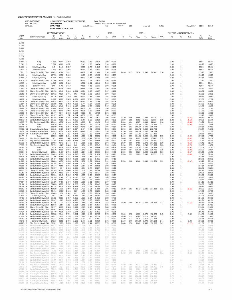
LIQUEFACTION POTENTIAL ANALYSIS (per Youd et al., 2001)
PROJECT NAME 11TH STREET EAST TRACY OVERHEAD FAULT INFOPROJECT NO. 2005-151-PSE GREAT VALLEY FAULT (REVERSE)CPT NO. CPT-07-002 FAULT M w = 6.7 MSF = 1.33 a max (g)= 0.465 VS30m(m/s)= 219.6 184.3
PERMANENT STRUCTURE
Depth qc fs v u v'(ft) (tsf) (tsf) (tsf) (tsf) (tsf)
0.4921.1481.8042.4613.1173.7734.4295.085 3 Clay 4.818 0.144 0.283 0.283 2.85 1.4835 0.99 0.299 1.00 1 81.84 81.845.741 3 Clay 7.581 0.262 0.32 0.32 2.76 1.4474 0.99 0.299 1.00 1 108.75 108.756.398 4 Silty Clay to Clay 6.2 0.13 0.357 0.357 2.75 1.413 0.99 0.298 1.00 1 95.86 95.867.054 1 Sensitive Fines 4.779 0.077 0.394 0.394 2.83 1.3802 0.99 0.298 1.00 1 81.62 81.627.71 5 Clayey Silt to Silty Clay 18.053 0.384 0.432 0.432 2.42 1.348 0.98 0.297 2.420 1.35 24.34 2.396 58.306 0.10 1.00 1 125.90 125.908.366 4 Silty Clay to Clay 12.733 0.392 0.469 0.469 2.68 1.3182 0.98 0.297 1.00 1 150.13 150.139.022 4 Silty Clay to Clay 6.907 0.143 0.507 0.507 2.84 1.2888 0.98 0.297 1.00 1 102.43 102.439.678 5 Clayey Silt to Silty Clay 8.032 0.108 0.544 0.544 2.71 1.2615 0.98 0.296 1.00 1 113.20 113.2010.335 4 Silty Clay to Clay 6.618 0.132 0.582 0.582 2.91 1.2346 0.98 0.296 1.00 1 99.51 99.5110.991 1 Sensitive Fines 2.09 0.02 0.618 0.618 3.38 1.2101 0.98 0.295 1.00 1 48.53 48.5311.647 5 Clayey Silt to Silty Clay 13.423 0.308 0.656 0.656 2.71 1.1853 0.98 0.295 1.00 1 155.21 155.2112.303 5 Clayey Silt to Silty Clay 18.176 0.548 0.694 0.009 0.684 2.68 1.1677 0.97 0.299 1.00 1 188.89 188.8912.959 5 Clayey Silt to Silty Clay 18.632 0.516 0.731 0.03 0.701 2.66 1.1573 0.97 0.307 1.00 1 192.31 192.3113.615 4 Silty Clay to Clay 14.176 0.481 0.769 0.05 0.719 2.83 1.1464 0.97 0.314 1.00 1 160.62 160.6214.272 4 Silty Clay to Clay 9.859 0.297 0.806 0.071 0.736 2.95 1.1364 0.97 0.321 1.00 1 127.62 127.6214.928 5 Clayey Silt to Silty Clay 21.534 0.633 0.844 0.091 0.753 2.65 1.1265 0.97 0.328 1.00 1 209.01 209.0115.584 5 Clayey Silt to Silty Clay 22.258 0.687 0.882 0.112 0.77 2.67 1.1168 0.97 0.335 1.00 1 213.20 213.2016.24 5 Clayey Silt to Silty Clay 12.694 0.341 0.919 0.132 0.787 2.85 1.1072 0.97 0.341 1.00 1 149.68 149.6816.896 5 Clayey Silt to Silty Clay 9.865 0.205 0.957 0.153 0.804 2.9 1.0978 0.96 0.347 1.00 1 127.62 127.6217.552 5 Clayey Silt to Silty Clay 8.689 0.148 0.994 0.173 0.821 2.92 1.0886 0.96 0.352 1.00 1 117.81 117.8118.209 5 Clayey Silt to Silty Clay 10.477 0.144 1.032 0.194 0.838 2.8 1.0795 0.96 0.358 1.00 1 132.96 132.9618.865 5 Clayey Silt to Silty Clay 11.207 0.239 1.07 0.214 0.856 2.88 1.07 0.96 0.363 1.00 1 139.18 139.1819.521 6 Sandy Silt to Clayey Silt 27.188 0.385 1.107 0.235 0.873 2.43 1.0613 0.96 0.367 2.430 1.06 28.85 2.439 70.375 0.11 1.00 1 (0.41) 160.51 55.2220.177 6 Sandy Silt to Clayey Silt 26.62 0.655 1.145 0.255 0.89 2.59 1.0526 0.96 0.372 2.590 1.05 28.02 3.266 91.518 0.15 1.00 1 (0.54) 160.82 57.0320.833 7 Silty Sand to Sandy Silt 46.249 0.772 1.183 0.276 0.908 2.3 1.0436 0.95 0.376 2.300 1.04 48.27 1.949 94.060 0.16 1.00 1 (0.56) 173.79 84.0421.49 9 Sand 121.78 0.422 1.224 0.296 0.928 1.56 1.0338 0.95 0.380 1.560 1.03 125.90 1.000 125.896 0.27 1.00 1 (0.93) 198.30 175.8422.146 9 Sand 185.09 0.483 1.265 0.316 0.948 1.34 1.0242 0.95 0.384 1.340 1.02 189.57 1.000 189.573 1.00 1 210.62 210.6222.802 10 Gravelly Sand to Sand 233.5 0.465 1.307 0.337 0.97 1.21 1.0138 0.95 0.387 1.210 1.01 236.73 1.000 236.730 1.00 1 218.42 218.4223.458 10 Gravelly Sand to Sand 245.03 0.374 1.348 0.357 0.991 1.15 1.0041 0.95 0.389 1.150 1.00 246.03 1.000 246.034 1.00 1 221.07 221.0724.114 10 Gravelly Sand to Sand 228.6 0.138 1.39 0.378 1.012 1.12 0.9946 0.94 0.392 1.120 0.99 227.35 1.000 227.355 1.00 1 220.33 220.3324.77 9 Sand 136.06 0.205 1.431 0.398 1.033 1.41 0.9852 0.94 0.395 1.410 0.99 134.05 1.000 134.046 0.30 0.99 1 (1.02) 207.09 177.5825.427 7 Silty Sand to Sandy Silt 32 0.446 1.47 0.419 1.051 2.44 0.9773 0.94 0.398 2.440 0.98 31.27 2.483 77.660 0.12 0.99 1 (0.41) 172.49 58.2926.083 7 Silty Sand to Sandy Silt 33.46 0.295 1.508 0.439 1.069 2.32 0.9696 0.94 0.400 2.320 0.97 32.44 2.015 65.358 0.11 0.99 1 (0.35) 174.22 57.6626.739 6 Sandy Silt to Clayey Silt 39.053 0.943 1.546 0.46 1.086 2.52 0.9624 0.94 0.402 2.520 0.96 37.58 2.872 107.926 0.20 0.98 1 (0.64) 178.41 71.5927.395 7 Silty Sand to Sandy Silt 70.791 1.223 1.584 0.48 1.104 2.23 0.9549 0.93 0.404 2.230 0.95 67.60 1.743 117.850 0.23 0.98 1 (0.75) 193.65 115.5728.051 9 Sand 142.1 0.476 1.625 0.501 1.124 1.57 0.9466 0.93 0.406 1.570 0.95 134.51 1.000 134.513 0.31 0.96 1 (0.97) 213.06 187.1028.707 9 Sand 136.76 0.606 1.666 0.521 1.145 1.65 0.9382 0.93 0.408 1.650 0.94 128.30 1.003 128.731 0.28 0.96 1 (0.88) 213.06 183.6429.364 8 Sand to Silty Sand 100.21 0.83 1.706 0.542 1.164 1.92 0.9306 0.92 0.409 1.920 0.93 93.26 1.208 112.685 0.21 0.96 1 (0.67) 205.52 144.7130.02 6 Sandy Silt to Clayey Silt 31.483 0.599 1.743 0.562 1.181 2.57 0.924 0.92 0.411 2.570 0.92 29.09 3.148 91.573 0.15 0.97 1 (0.48) 177.42 57.6630.676 5 Clayey Silt to Silty Clay 17.54 0.386 1.781 0.583 1.198 2.85 0.9174 0.92 0.412 0.96 1 183.33 183.3331.332 6 Sandy Silt to Clayey Silt 34.457 0.892 1.818 0.603 1.215 2.63 0.911 0.91 0.413 0.96 1 280.72 280.7231.988 6 Sandy Silt to Clayey Silt 39.883 0.976 1.856 0.624 1.232 2.57 0.9046 0.91 0.414 2.570 0.90 36.08 3.148 113.573 0.22 0.96 1 (0.67) 185.13 70.1032.644 6 Sandy Silt to Clayey Silt 25.784 0.577 1.894 0.644 1.25 2.71 0.898 0.91 0.415 0.96 1 234.31 234.3133.301 6 Sandy Silt to Clayey Silt 24.447 0.566 1.931 0.664 1.267 2.74 0.8918 0.90 0.415 0.95 1 227.64 227.6433.957 6 Sandy Silt to Clayey Silt 26.157 0.7 1.969 0.685 1.284 2.76 0.8857 0.90 0.416 0.95 1 238.34 238.3434.613 5 Clayey Silt to Silty Clay 20.365 0.508 2.006 0.705 1.301 2.84 0.8796 0.89 0.416 0.95 1 204.96 204.9635.269 6 Sandy Silt to Clayey Silt 22.676 0.501 2.044 0.726 1.318 2.76 0.8737 0.89 0.417 0.95 1 220.96 220.9635.925 6 Sandy Silt to Clayey Silt 34.964 0.849 2.082 0.746 1.335 2.62 0.8679 0.88 0.417 0.94 1 290.20 290.2036.581 6 Sandy Silt to Clayey Silt 38.105 0.94 2.119 0.767 1.352 2.6 0.8621 0.88 0.416 0.94 1 189.37 189.3737.238 6 Sandy Silt to Clayey Silt 26.77 0.689 2.157 0.787 1.369 2.78 0.8564 0.87 0.416 0.94 1 239.42 239.4237.894 6 Sandy Silt to Clayey Silt 22.37 0.488 2.194 0.808 1.386 2.81 0.8507 0.87 0.416 0.94 1 214.11 214.1138.55 6 Sandy Silt to Clayey Silt 29.823 0.771 2.232 0.828 1.404 2.74 0.8449 0.86 0.415 0.93 1 256.90 256.9039.206 6 Sandy Silt to Clayey Silt 34.234 0.975 2.269 0.849 1.421 2.72 0.8394 0.86 0.414 0.93 1 280.77 280.7739.862 6 Sandy Silt to Clayey Silt 48.828 1.035 2.307 0.869 1.438 2.51 0.834 0.85 0.413 2.510 0.83 40.72 2.820 114.813 0.22 0.93 1 (0.66) 198.26 76.9440.518 6 Sandy Silt to Clayey Silt 28.174 0.591 2.345 0.89 1.455 2.73 0.8286 0.85 0.412 0.93 1 247.83 247.8341.175 5 Clayey Silt to Silty Clay 37.069 1.278 2.382 0.91 1.472 2.75 0.8234 0.84 0.411 0.93 1 294.70 294.7041.831 4 Silty Clay to Clay 27.2 1.067 2.42 0.931 1.489 2.91 0.8181 0.83 0.410 0.92 1 242.95 242.9542.487 6 Sandy Silt to Clayey Silt 23.89 0.593 2.457 0.951 1.506 2.84 0.813 0.83 0.408 0.92 1 224.90 224.9043.143 6 Sandy Silt to Clayey Silt 38.267 1.023 2.495 0.972 1.523 2.68 0.8079 0.82 0.407 0.92 1 302.31 302.3143.799 6 Sandy Silt to Clayey Silt 62.03 1.77 2.533 0.992 1.541 2.53 0.8026 0.82 0.405 2.530 0.80 49.79 2.925 145.615 0.37 0.92 1 (1.11) 208.37 97.0944.455 6 Sandy Silt to Clayey Silt 41.873 1.154 2.57 1.013 1.558 2.67 0.7977 0.81 0.403 0.92 1 317.67 317.6745.112 5 Clayey Silt to Silty Clay 23.177 0.675 2.608 1.033 1.575 2.93 0.7928 0.80 0.402 0.91 1 219.31 219.3145.768 5 Clayey Silt to Silty Clay 18.961 0.428 2.645 1.053 1.592 2.95 0.788 0.80 0.400 0.91 1 193.91 193.9146.424 6 Sandy Silt to Clayey Silt 29.449 0.836 2.683 1.074 1.609 2.82 0.7832 0.79 0.398 0.91 1 256.46 256.4647.08 6 Sandy Silt to Clayey Silt 68.508 2.144 2.721 1.094 1.626 2.54 0.7785 0.78 0.396 2.540 0.78 53.33 2.979 158.876 0.45 0.91 1 1.39 214.26 214.2647.736 6 Sandy Silt to Clayey Silt 79.977 2.435 2.758 1.115 1.643 2.49 0.7738 0.78 0.394 2.490 0.77 61.89 2.718 168.237 0.91 1 219.13 219.1348.392 6 Sandy Silt to Clayey Silt 97.211 2.746 2.796 1.135 1.66 2.4 0.7692 0.77 0.392 2.400 0.77 74.78 2.312 172.914 0.90 1 225.38 225.3849.049 8 Sand to Silty Sand 140.13 2.161 2.835 1.156 1.68 2.11 0.7639 0.76 0.389 2.110 0.76 107.04 1.473 157.692 0.44 0.87 1 1.33 237.08 237.0849.705 7 Silty Sand to Sandy Silt 80.901 2.073 2.874 1.176 1.698 2.44 0.7591 0.76 0.387 2.440 0.76 61.42 2.483 152.503 0.41 0.90 1 (1.27) 221.39 221.3950.361 6 Sandy Silt to Clayey Silt 33.477 0.959 2.912 1.197 1.715 2.8 0.7547 0.75 0.384 0.90 1 276.55 276.5551.017 6 Sandy Silt to Clayey Silt 26.352 0.546 2.949 1.217 1.732 2.82 0.7503 0.74 0.382 0.90 1 239.30 239.3051.673 6 Sandy Silt to Clayey Silt 28.553 0.599 2.987 1.238 1.749 2.78 0.746 0.74 0.380 0.89 1 255.06 255.0652.329 6 Sandy Silt to Clayey Silt 29.249 0.743 3.024 1.258 1.766 2.8 0.7417 0.73 0.377 0.89 1 263.01 263.0152.986 6 Sandy Silt to Clayey Silt 27.272 0.771 3.062 1.279 1.783 2.86 0.7375 0.72 0.375 0.89 1 252.23 252.2353.642 5 Clayey Silt to Silty Clay 24.837 0.763 3.1 1.299 1.801 2.94 0.7331 0.72 0.373 0.89 1 236.36 236.3654.298 5 Clayey Silt to Silty Clay 17.824 0.46 3.137 1.32 1.818 3.04 0.729 0.71 0.370 0.89 1 193.01 193.0154.954 6 Sandy Silt to Clayey Silt 23.231 0.583 3.175 1.34 1.835 2.91 0.7249 0.70 0.368 0.89 1 228.45 228.4555.61 6 Sandy Silt to Clayey Silt 40.868 1.24 3.212 1.361 1.852 2.75 0.7208 0.70 0.366 0.88 1 319.76 319.7656.266 5 Clayey Silt to Silty Clay 34.034 1.036 3.25 1.381 1.869 2.85 0.7168 0.69 0.363 0.88 1 280.41 280.4156.923 6 Sandy Silt to Clayey Silt 19.022 0.404 3.288 1.401 1.886 2.99 0.7129 0.69 0.361 0.88 1 200.42 200.4257.579 7 Silty Sand to Sandy Silt 48.75 0.728 3.326 1.422 1.904 2.51 0.7088 0.68 0.359 2.510 0.71 34.55 2.820 97.420 0.17 0.88 1 0.54 214.64 67.1758.235 7 Silty Sand to Sandy Silt 67.923 1.195 3.365 1.442 1.922 2.45 0.7047 0.67 0.357 2.450 0.70 47.86 2.528 121.010 0.24 0.88 1 0.80 223.76 91.3358.891 6 Sandy Silt to Clayey Silt 24.292 0.614 3.403 1.463 1.94 2.96 0.7006 0.67 0.354 0.88 1 227.41 227.4159.547 6 Sandy Silt to Clayey Silt 23.484 0.431 3.44 1.483 1.957 2.88 0.6969 0.66 0.352 0.87 1 226.13 226.1360.203 6 Sandy Silt to Clayey Silt 26.77 0.547 3.478 1.504 1.974 2.84 0.6931 0.66 0.350 0.87 1 248.00 248.0060.86 6 Sandy Silt to Clayey Silt 34.262 0.855 3.515 1.524 1.991 2.79 0.6894 0.65 0.348 0.87 1 289.05 289.0561.516 7 Silty Sand to Sandy Silt 73.961 1.627 3.554 1.545 2.009 2.48 0.6856 0.65 0.346 2.480 0.69 50.71 2.669 135.351 0.31 0.87 1 1.04 229.68 98.7562.172 8 Sand to Silty Sand 151.58 2.3 3.594 1.565 2.028 2.14 0.6815 0.64 0.344 2.140 0.68 103.31 1.532 158.265 0.45 0.84 1 1.45 251.99 251.9962.828 6 Sandy Silt to Clayey Silt 77.013 2.281 3.631 1.586 2.045 2.57 0.678 0.64 0.342 2.570 0.68 52.21 3.148 164.362 0.87 1 231.26 231.2663.484 10 Gravelly Sand to Sand 282.81 1.813 3.673 1.606 2.067 1.69 0.6734 0.63 0.340 1.690 0.67 190.44 1.031 196.363 0.77 1 274.69 274.6964.14 10 Gravelly Sand to Sand 437.49 1.48 3.715 1.627 2.088 1.38 0.6691 0.63 0.338 1.380 0.67 292.72 1.000 292.723 0.74 1 291.52 291.5264.797 10 Gravelly Sand to Sand 394.12 0.915 3.757 1.647 2.109 1.34 0.6649 0.62 0.336 1.340 0.66 262.03 1.000 262.031 0.74 1 288.37 288.3765.453 10 Gravelly Sand to Sand 388.42 1.085 3.798 1.668 2.131 1.39 0.6605 0.62 0.333 1.390 0.66 256.54 1.000 256.537 0.74 1 288.63 288.6366.109 10 Gravelly Sand to Sand 396.92 0.942 3.84 1.688 2.152 1.35 0.6563 0.61 0.332 1.350 0.66 260.51 1.000 260.505 0.74 1 290.21 290.2166.765 10 Gravelly Sand to Sand 255.47 1.328 3.882 1.709 2.173 1.69 0.6522 0.61 0.330 1.690 0.65 166.63 1.031 171.807 0.77 1 274.77 274.77
CQ qc1N KC (qc1N)cs CRR7.5 K K F.S.Vs
(m/s)Vs,liq
(m/s)
CPT RESULT INPUT CSR CRR 7.5 F.S.=(CRR 7.5 /CSR)*MSF*K *K
Soil Behavior Type Ic* CN* d CSR Ic
3/21/2014 Liquefaction CPT-07-002 (YOUD with VS_NEW) 1 of 1
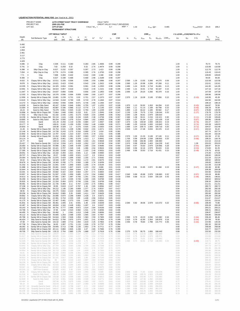
LIQUEFACTION POTENTIAL ANALYSIS (per Youd et al., 2001)
PROJECT NAME 11TH STREET EAST TRACY OVERHEAD FAULT INFOPROJECT NO. 2005-151-PSE GREAT VALLEY FAULT (REVERSE)CPT NO. CPT-07-003 FAULT M w = 6.7 MSF = 1.33 a max (g)= 0.465 VS30m(m/s)= 231.6 186.2
PERMANENT STRUCTURE
Depth qc fs v u v'(ft) (tsf) (tsf) (tsf) (tsf) (tsf)
0.4921.1481.8042.4613.1173.7734.4295.085 3 Clay 4.339 0.111 0.283 0.283 2.85 1.4835 0.99 0.299 1.00 1 76.73 76.735.741 3 Clay 7.82 0.259 0.32 0.32 2.74 1.4474 0.99 0.299 1.00 1 110.99 110.996.398 4 Silty Clay to Clay 8.027 0.232 0.357 0.357 2.73 1.413 0.99 0.298 1.00 1 112.76 112.767.054 4 Silty Clay to Clay 8.779 0.274 0.395 0.395 2.76 1.3793 0.99 0.298 1.00 1 119.43 119.437.71 3 Clay 7.698 0.283 0.432 0.432 2.89 1.348 0.98 0.297 1.00 1 109.65 109.658.366 3 Clay 6.027 0.198 0.468 0.468 2.98 1.3189 0.98 0.297 1.00 1 94.00 94.009.022 5 Clayey Silt to Silty Clay 10.511 0.156 0.506 0.506 2.59 1.2896 0.98 0.297 2.590 1.29 13.55 3.266 44.270 0.09 1.00 1 122.58 122.589.678 5 Clayey Silt to Silty Clay 16.621 0.423 0.543 0.543 2.58 1.2622 0.98 0.296 2.580 1.26 20.98 3.206 67.268 0.11 1.00 1 132.61 132.6110.335 5 Clayey Silt to Silty Clay 24.325 0.654 0.581 0.581 2.49 1.2353 0.98 0.296 2.490 1.24 30.05 2.718 81.681 0.13 1.00 1 141.95 141.9510.991 5 Clayey Silt to Silty Clay 28.024 0.857 0.618 0.618 2.49 1.2101 0.98 0.295 2.490 1.21 33.91 2.718 92.187 0.15 1.00 1 147.16 147.1611.647 5 Clayey Silt to Silty Clay 24.637 0.856 0.656 0.656 2.59 1.1853 0.98 0.295 2.590 1.19 29.20 3.266 95.379 0.16 1.00 1 147.09 147.0912.303 5 Clayey Silt to Silty Clay 18.376 0.596 0.694 0.009 0.684 2.69 1.1677 0.97 0.299 1.00 1 190.96 190.9612.959 6 Sandy Silt to Clayey Silt 15.881 0.239 0.731 0.03 0.701 2.57 1.1573 0.97 0.307 2.570 1.16 18.38 3.148 57.856 0.10 1.00 1 (0.43) 140.95 45.3913.615 5 Clayey Silt to Silty Clay 14.544 0.418 0.769 0.05 0.719 2.78 1.1464 0.97 0.314 1.00 1 162.90 162.9014.272 5 Clayey Silt to Silty Clay 19.802 0.556 0.806 0.071 0.736 2.66 1.1364 0.97 0.321 1.00 1 198.16 198.1614.928 8 Sand to Silty Sand 45.247 0.264 0.846 0.091 0.755 1.97 1.1253 0.97 0.328 1.970 1.13 50.92 1.263 64.294 0.10 1.00 1 (0.43) 164.87 78.5015.584 8 Sand to Silty Sand 45.887 0.186 0.886 0.112 0.774 1.9 1.1145 0.97 0.335 1.900 1.11 51.14 1.189 60.798 0.10 1.00 1 (0.40) 166.28 76.9416.24 8 Sand to Silty Sand 76.479 0.661 0.925 0.132 0.793 1.89 1.1039 0.97 0.341 1.890 1.10 84.42 1.180 99.582 0.17 1.00 1 (0.67) 178.89 130.9516.896 6 Sandy Silt to Clayey Silt 72.864 1.848 0.963 0.153 0.81 2.23 1.0945 0.96 0.347 2.230 1.09 79.75 1.743 139.044 0.33 1.00 1 (1.27) 178.78 178.7817.552 4 Silty Clay to Clay 52.182 2.435 1.001 0.173 0.828 2.54 1.0848 0.96 0.352 2.540 1.08 56.61 2.979 168.633 1.00 1 172.18 172.1818.209 6 Sandy Silt to Clayey Silt 55.134 1.616 1.038 0.194 0.845 2.38 1.0758 0.96 0.357 2.380 1.08 59.31 2.233 132.421 0.30 1.00 1 (1.11) 174.38 109.6518.865 8 Sand to Silty Sand 86.254 0.595 1.078 0.214 0.864 1.82 1.0659 0.96 0.362 1.820 1.07 91.94 1.122 103.109 0.18 1.00 1 (0.67) 185.96 138.6819.521 9 Sand 101.28 0.293 1.119 0.235 0.884 1.57 1.0557 0.96 0.367 1.570 1.06 106.92 1.000 106.921 0.19 1.00 1 (0.70) 191.07 148.1720.177 9 Sand 106.01 0.182 1.159 0.255 0.904 1.48 1.0456 0.96 0.371 1.480 1.05 110.84 1.000 110.843 0.21 1.00 1 (0.74) 193.38 149.0320.833 9 Sand 105.98 0.329 1.2 0.276 0.925 1.59 1.0353 0.95 0.374 1.590 1.04 109.72 1.000 109.719 0.20 1.00 1 (0.72) 194.57 152.4821.49 6 Sandy Silt to Clayey Silt 26.754 0.531 1.238 0.296 0.942 2.55 1.0271 0.95 0.379 2.550 1.03 27.48 3.034 83.376 0.13 1.00 1 (0.47) 163.52 55.2222.146 6 Sandy Silt to Clayey Silt 14.728 0.243 1.275 0.316 0.959 2.74 1.019 0.95 0.382 1.00 1 167.74 167.7422.802 6 Sandy Silt to Clayey Silt 13.797 0.242 1.313 0.337 0.976 2.78 1.011 0.95 0.386 1.00 1 162.26 162.2623.458 6 Sandy Silt to Clayey Silt 21.262 0.309 1.351 0.357 0.993 2.57 1.0032 0.95 0.389 2.570 1.00 21.33 3.148 67.146 0.11 1.00 1 (0.37) 161.58 47.3324.114 9 Sand 105.31 0.461 1.391 0.378 1.013 1.7 0.9941 0.94 0.392 1.700 0.99 104.69 1.038 108.655 0.20 1.00 1 (0.68) 199.25 150.7624.77 9 Sand 169.54 1.031 1.432 0.398 1.034 1.61 0.9848 0.94 0.395 1.610 0.98 166.96 1.000 166.960 0.99 1 213.16 213.1625.427 7 Silty Sand to Sandy Silt 112.54 2.034 1.471 0.419 1.052 2.07 0.9769 0.94 0.397 2.070 0.98 109.94 1.403 154.239 0.42 0.99 1 1.39 203.03 203.0326.083 6 Sandy Silt to Clayey Silt 44.996 1.382 1.508 0.439 1.069 2.54 0.9696 0.94 0.400 2.540 0.97 43.63 2.979 129.966 0.28 0.99 1 (0.94) 180.97 84.0426.739 6 Sandy Silt to Clayey Silt 33.421 0.707 1.546 0.46 1.086 2.54 0.9624 0.94 0.402 2.540 0.96 32.16 2.979 95.815 0.16 0.98 1 (0.53) 174.83 62.2527.395 6 Sandy Silt to Clayey Silt 35.209 0.636 1.583 0.48 1.103 2.49 0.9553 0.93 0.405 2.490 0.96 33.63 2.718 91.431 0.15 0.98 1 (0.49) 176.76 63.6328.051 5 Clayey Silt to Silty Clay 16.182 0.393 1.621 0.501 1.12 2.88 0.9483 0.93 0.407 0.98 1 174.35 174.3528.707 5 Clayey Silt to Silty Clay 20.07 0.498 1.659 0.521 1.137 2.8 0.9414 0.93 0.409 0.97 1 199.92 199.9229.364 6 Sandy Silt to Clayey Silt 21.975 0.429 1.696 0.542 1.155 2.71 0.9342 0.92 0.410 0.97 1 212.24 212.2430.02 5 Clayey Silt to Silty Clay 18.326 0.397 1.734 0.562 1.172 2.81 0.9275 0.92 0.412 0.97 1 189.92 189.9230.676 6 Sandy Silt to Clayey Silt 18.343 0.295 1.771 0.583 1.189 2.74 0.9209 0.92 0.413 0.97 1 190.83 190.8331.332 6 Sandy Silt to Clayey Silt 21.841 0.457 1.809 0.603 1.206 2.74 0.9144 0.91 0.414 0.96 1 213.38 213.3831.988 6 Sandy Silt to Clayey Silt 35.081 0.618 1.847 0.624 1.223 2.52 0.908 0.91 0.415 2.520 0.91 31.85 2.872 91.468 0.15 0.96 1 (0.47) 181.86 60.9032.644 6 Sandy Silt to Clayey Silt 21.546 0.413 1.884 0.644 1.24 2.75 0.9016 0.91 0.416 0.96 1 209.38 209.3833.301 6 Sandy Silt to Clayey Silt 20.682 0.322 1.922 0.664 1.257 2.71 0.8954 0.90 0.417 0.96 1 204.90 204.9033.957 6 Sandy Silt to Clayey Silt 51.597 1.535 1.959 0.685 1.274 2.54 0.8892 0.90 0.417 2.540 0.89 45.88 2.979 136.683 0.32 0.95 1 (0.97) 193.28 88.8834.613 6 Sandy Silt to Clayey Silt 57.891 1.957 1.997 0.705 1.291 2.55 0.8832 0.89 0.418 2.550 0.88 51.13 3.034 155.134 0.43 0.95 1 (1.30) 196.81 196.8135.269 6 Sandy Silt to Clayey Silt 40.189 1.223 2.035 0.726 1.309 2.65 0.8768 0.89 0.418 0.95 1 309.52 309.5235.925 6 Sandy Silt to Clayey Silt 21.334 0.464 2.072 0.746 1.326 2.81 0.8709 0.88 0.418 0.95 1 208.34 208.3436.581 6 Sandy Silt to Clayey Silt 21.735 0.384 2.11 0.767 1.343 2.75 0.8651 0.88 0.417 0.94 1 211.51 211.5137.238 6 Sandy Silt to Clayey Silt 33.95 0.819 2.147 0.787 1.36 2.65 0.8594 0.87 0.417 0.94 1 280.72 280.7237.894 5 Clayey Silt to Silty Clay 34.212 1.146 2.185 0.808 1.377 2.74 0.8537 0.87 0.417 0.94 1 282.56 282.5638.55 5 Clayey Silt to Silty Clay 28.475 0.822 2.222 0.828 1.394 2.78 0.8481 0.86 0.416 0.94 1 251.62 251.6239.206 6 Sandy Silt to Clayey Silt 34.652 0.865 2.26 0.849 1.411 2.67 0.8426 0.86 0.415 0.93 1 282.66 282.6639.862 5 Clayey Silt to Silty Clay 25.996 0.974 2.298 0.869 1.428 2.9 0.8371 0.85 0.415 0.93 1 235.28 235.2840.518 5 Clayey Silt to Silty Clay 22.381 0.753 2.335 0.89 1.446 2.94 0.8314 0.85 0.413 0.93 1 214.47 214.4741.175 6 Sandy Silt to Clayey Silt 22.487 0.481 2.373 0.91 1.463 2.82 0.8261 0.84 0.412 0.93 1 215.91 215.9141.831 6 Sandy Silt to Clayey Silt 46.361 1.005 2.41 0.931 1.48 2.54 0.8209 0.83 0.411 2.540 0.82 38.06 2.979 113.372 0.22 0.92 1 (0.65) 198.49 73.8642.487 6 Sandy Silt to Clayey Silt 48.694 1.344 2.448 0.951 1.497 2.6 0.8157 0.83 0.409 0.92 1 200.28 200.2843.143 6 Sandy Silt to Clayey Silt 36.791 0.777 2.486 0.972 1.514 2.64 0.8106 0.82 0.408 0.92 1 293.21 293.2143.799 5 Clayey Silt to Silty Clay 37.95 1.442 2.523 0.992 1.531 2.79 0.8056 0.82 0.406 0.92 1 299.21 299.2144.455 5 Clayey Silt to Silty Clay 26.492 1 2.561 1.013 1.548 2.93 0.8006 0.81 0.405 0.92 1 238.97 238.9745.112 6 Sandy Silt to Clayey Silt 45.665 1.263 2.598 1.033 1.565 2.64 0.7957 0.80 0.403 0.91 1 336.80 336.8045.768 6 Sandy Silt to Clayey Silt 54.644 1.593 2.636 1.053 1.583 2.59 0.7905 0.80 0.401 2.590 0.79 43.20 3.266 141.082 0.34 0.91 1 (1.04) 206.43 86.4546.424 7 Silty Sand to Sandy Silt 54.622 0.794 2.675 1.074 1.601 2.41 0.7854 0.79 0.399 2.410 0.79 42.90 2.354 100.976 0.18 0.91 1 (0.54) 207.06 78.5047.08 7 Silty Sand to Sandy Silt 101.02 1.809 2.713 1.094 1.619 2.25 0.7804 0.78 0.396 2.250 0.78 78.84 1.798 141.772 0.35 0.90 1 (1.04) 224.95 140.4047.736 5 Clayey Silt to Silty Clay 34.63 1.067 2.751 1.115 1.636 2.79 0.7757 0.78 0.394 0.91 1 282.30 282.3048.392 6 Sandy Silt to Clayey Silt 29.945 0.713 2.788 1.135 1.653 2.79 0.7711 0.77 0.392 0.90 1 258.08 258.0849.049 6 Sandy Silt to Clayey Silt 40.111 0.884 2.826 1.156 1.67 2.65 0.7666 0.76 0.390 0.90 1 310.77 310.7749.705 7 Silty Sand to Sandy Silt 119.13 2.704 2.865 1.176 1.688 2.27 0.7618 0.76 0.388 2.270 0.76 90.75 1.856 168.440 0.88 1 232.50 232.5050.361 7 Silty Sand to Sandy Silt 149.87 3.457 2.903 1.197 1.707 2.21 0.7568 0.75 0.385 2.210 0.76 113.42 1.692 191.859 0.87 1 240.19 240.1951.017 6 Sandy Silt to Clayey Silt 88.505 3.341 2.941 1.217 1.724 2.54 0.7524 0.74 0.383 2.540 0.75 66.59 2.979 198.371 0.90 1 224.88 224.8851.673 7 Silty Sand to Sandy Silt 100.31 2.711 2.98 1.238 1.742 2.4 0.7478 0.74 0.380 2.400 0.75 75.01 2.312 173.460 0.89 1 229.22 229.2252.329 7 Silty Sand to Sandy Silt 68.497 1.592 3.018 1.258 1.76 2.49 0.7432 0.73 0.378 2.490 0.74 50.91 2.718 138.393 0.33 0.89 1 (1.03) 218.71 98.7552.986 6 Sandy Silt to Clayey Silt 48.255 1.211 3.056 1.279 1.777 2.64 0.739 0.72 0.376 0.89 1 347.15 347.1553.642 5 Clayey Silt to Silty Clay 37.744 1.262 3.093 1.299 1.794 2.82 0.7348 0.72 0.373 0.89 1 297.73 297.7354.298 6 Sandy Silt to Clayey Silt 36.451 1.015 3.131 1.32 1.811 2.79 0.7307 0.71 0.371 0.89 1 291.36 291.3654.954 6 Sandy Silt to Clayey Silt 36.713 1.089 3.169 1.34 1.829 2.8 0.7263 0.70 0.369 0.89 1 292.86 292.8655.61 6 Sandy Silt to Clayey Silt 35.142 0.993 3.206 1.361 1.846 2.81 0.7223 0.70 0.366 0.88 1 285.05 285.0556.266 6 Sandy Silt to Clayey Silt 27.762 0.588 3.244 1.381 1.863 2.84 0.7183 0.69 0.364 0.88 1 246.06 246.0656.923 6 Sandy Silt to Clayey Silt 32.101 0.917 3.281 1.401 1.88 2.86 0.7143 0.69 0.362 0.88 1 269.72 269.7257.579 5 Clayey Silt to Silty Clay 38 1.263 3.319 1.422 1.897 2.83 0.7104 0.68 0.359 0.88 1 300.45 300.4558.235 6 Sandy Silt to Clayey Silt 41.092 1.231 3.357 1.442 1.914 2.77 0.7065 0.67 0.357 0.88 1 316.67 316.6758.891 5 Clayey Silt to Silty Clay 42.016 1.472 3.394 1.463 1.931 2.8 0.7027 0.67 0.355 0.88 1 325.00 325.0059.547 11 Sitff Fine-Grained 93.022 4.093 3.437 1.483 1.954 2.6 0.6975 0.66 0.352 0.87 1 234.47 234.4760.203 11 Sitff Fine-Grained 95.885 4.651 3.48 1.504 1.976 2.63 0.6927 0.66 0.350 0.87 1 534.68 534.6860.86 5 Clayey Silt to Silty Clay 104.39 4.169 3.517 1.524 1.993 2.55 0.689 0.65 0.348 2.550 0.69 71.92 3.034 218.228 0.87 1 238.96 238.9661.516 8 Sand to Silty Sand 160.25 2.696 3.557 1.545 2.012 2.15 0.6849 0.65 0.346 2.150 0.68 109.76 1.553 170.439 0.83 1 253.29 253.2962.172 6 Sandy Silt to Clayey Silt 150.88 5.252 3.595 1.565 2.029 2.39 0.6813 0.64 0.344 2.390 0.68 102.80 2.272 233.560 0.84 1 251.87 251.8762.828 8 Sand to Silty Sand 217.62 4.581 3.634 1.586 2.049 2.12 0.6771 0.64 0.342 2.120 0.68 147.36 1.492 219.883 0.80 1 264.87 264.8763.484 9 Sand 287.96 4.176 3.675 1.606 2.069 1.92 0.673 0.63 0.340 1.920 0.67 193.80 1.208 234.158 0.77 1 275.41 275.4164.14 9 Sand 332.64 3.553 3.716 1.627 2.089 1.79 0.6689 0.63 0.338 1.790 0.67 222.50 1.099 244.624 0.75 1 281.35 281.3564.797 10 Gravelly Sand to Sand 376.44 2.341 3.758 1.647 2.11 1.59 0.6647 0.62 0.336 1.590 0.66 250.20 1.000 250.201 0.74 1 286.68 286.6865.453 10 Gravelly Sand to Sand 548.67 2.491 3.799 1.668 2.132 1.38 0.6603 0.62 0.333 1.380 0.66 362.27 1.000 362.270 0.74 1 301.93 301.9366.109 10 Gravelly Sand to Sand 634.41 1.692 3.841 1.688 2.153 1.19 0.6561 0.61 0.332 1.190 0.66 416.25 1.000 416.252 0.74 1 308.49 308.4966.765 10 Gravelly Sand to Sand 535.96 1.428 3.883 1.709 2.174 1.26 0.652 0.61 0.330 1.260 0.65 349.47 1.000 349.469 0.73 1 302.60 302.60
CQ qc1N KC (qc1N)cs CRR7.5 K K F.S.Vs
(m/s)Vs,liq
(m/s)
CPT RESULT INPUT CSR CRR 7.5 F.S.=(CRR 7.5 /CSR)*MSF*K *K
Soil Behavior Type Ic* CN* d CSR Ic
3/21/2014 Liquefaction CPT-07-003 (YOUD with VS_NEW) 1 of 1
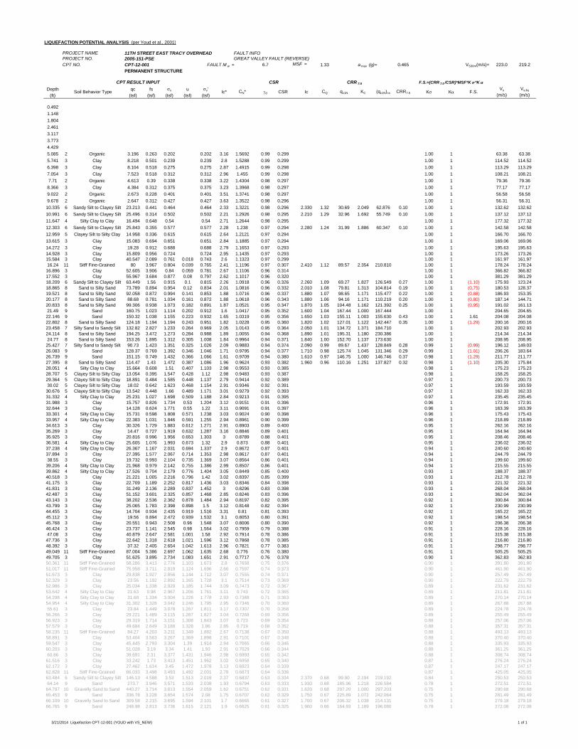
LIQUEFACTION POTENTIAL ANALYSIS (per Youd et al., 2001)
PROJECT NAME 11TH STREET EAST TRACY OVERHEAD FAULT INFOPROJECT NO. 2005-151-PSE GREAT VALLEY FAULT (REVERSE)CPT NO. CPT-12-001 FAULT M w = 6.7 MSF = 1.33 a max (g)= 0.465 VS30m(m/s)= 223.0 219.2
PERMANENT STRUCTURE
Depth qc fs v u v'(ft) (tsf) (tsf) (tsf) (tsf) (tsf)
0.4921.1481.8042.4613.1173.7734.4295.085 2 Organic 3.196 0.263 0.202 0.202 3.16 1.5692 0.99 0.299 1.00 1 63.38 63.385.741 3 Clay 8.218 0.501 0.239 0.239 2.8 1.5288 0.99 0.299 1.00 1 114.52 114.526.398 3 Clay 8.104 0.518 0.275 0.275 2.87 1.4915 0.99 0.298 1.00 1 113.29 113.297.054 3 Clay 7.523 0.518 0.312 0.312 2.96 1.455 0.99 0.298 1.00 1 108.21 108.217.71 2 Organic 4.613 0.39 0.338 0.338 3.22 1.4304 0.98 0.297 1.00 1 79.36 79.368.366 3 Clay 4.384 0.312 0.375 0.375 3.23 1.3968 0.98 0.297 1.00 1 77.17 77.179.022 2 Organic 2.673 0.228 0.401 0.401 3.51 1.3741 0.98 0.297 1.00 1 56.58 56.589.678 2 Organic 2.647 0.312 0.427 0.427 3.63 1.3522 0.98 0.296 1.00 1 56.31 56.3110.335 6 Sandy Silt to Clayey Silt 23.213 0.441 0.464 0.464 2.33 1.3221 0.98 0.296 2.330 1.32 30.69 2.049 62.876 0.10 1.00 1 132.62 132.6210.991 6 Sandy Silt to Clayey Silt 25.496 0.314 0.502 0.502 2.21 1.2926 0.98 0.295 2.210 1.29 32.96 1.692 55.749 0.10 1.00 1 137.12 137.1211.647 4 Silty Clay to Clay 16.494 0.648 0.54 0.54 2.71 1.2644 0.98 0.295 1.00 1 177.32 177.3212.303 6 Sandy Silt to Clayey Silt 25.843 0.355 0.577 0.577 2.28 1.238 0.97 0.294 2.280 1.24 31.99 1.886 60.347 0.10 1.00 1 142.58 142.5812.959 5 Clayey Silt to Silty Clay 14.958 0.336 0.615 0.615 2.64 1.2121 0.97 0.294 1.00 1 166.70 166.7013.615 3 Clay 15.083 0.694 0.651 0.651 2.84 1.1885 0.97 0.294 1.00 1 169.06 169.0614.272 3 Clay 19.28 0.912 0.688 0.688 2.79 1.1653 0.97 0.293 1.00 1 195.63 195.6314.928 3 Clay 15.809 0.956 0.724 0.724 2.95 1.1435 0.97 0.293 1.00 1 173.26 173.2615.584 3 Clay 40.547 2.089 0.761 0.018 0.743 2.6 1.1323 0.97 0.299 1.00 1 161.97 161.9716.24 11 Sitff Fine-Grained 80 3.967 0.804 0.039 0.765 2.41 1.1196 0.97 0.307 2.410 1.12 89.57 2.354 210.810 1.00 1 178.24 178.2416.896 3 Clay 52.605 3.906 0.84 0.059 0.781 2.67 1.1106 0.96 0.314 1.00 1 366.82 366.8217.552 3 Clay 55.967 3.684 0.877 0.08 0.797 2.62 1.1017 0.96 0.320 1.00 1 381.29 381.2918.209 6 Sandy Silt to Clayey Silt 63.449 1.56 0.915 0.1 0.815 2.26 1.0918 0.96 0.326 2.260 1.09 69.27 1.827 126.549 0.27 1.00 1 (1.10) 175.93 123.2418.865 8 Sand to Silty Sand 73.789 0.894 0.954 0.12 0.834 2.01 1.0816 0.96 0.332 2.010 1.08 79.81 1.313 104.814 0.19 1.00 1 (0.75) 180.53 128.3719.521 8 Sand to Silty Sand 92.058 0.872 0.994 0.141 0.853 1.88 1.0716 0.96 0.337 1.880 1.07 98.65 1.171 115.477 0.22 1.00 1 (0.88) 186.93 153.3520.177 8 Sand to Silty Sand 88.68 0.781 1.034 0.161 0.872 1.88 1.0618 0.96 0.343 1.880 1.06 94.16 1.171 110.219 0.20 1.00 1 (0.80) 187.14 144.7120.833 8 Sand to Silty Sand 99.306 0.938 1.073 0.182 0.891 1.87 1.0521 0.95 0.347 1.870 1.05 104.48 1.162 121.392 0.25 1.00 1 (0.95) 191.02 161.1321.49 9 Sand 160.75 1.023 1.114 0.202 0.912 1.6 1.0417 0.95 0.352 1.600 1.04 167.44 1.000 167.444 1.00 1 204.65 204.6522.146 9 Sand 150.32 1.038 1.155 0.223 0.932 1.65 1.0319 0.95 0.356 1.650 1.03 155.11 1.003 155.630 0.43 1.00 1 1.61 204.08 204.0822.802 8 Sand to Silty Sand 124.18 1.194 1.194 0.243 0.951 1.82 1.0228 0.95 0.360 1.820 1.02 127.01 1.122 142.447 0.35 1.00 1 (1.29) 200.16 200.1623.458 7 Silty Sand to Sandy Silt 132.82 2.827 1.233 0.264 0.969 2.05 1.0143 0.95 0.364 2.050 1.01 134.72 1.371 184.710 1.00 1 202.93 202.9324.114 8 Sand to Silty Sand 194.25 3.472 1.273 0.284 0.988 1.89 1.0055 0.94 0.368 1.890 1.01 195.31 1.180 230.386 1.00 1 214.34 214.3424.77 8 Sand to Silty Sand 153.26 1.895 1.312 0.305 1.008 1.84 0.9964 0.94 0.371 1.840 1.00 152.70 1.137 173.630 1.00 1 208.95 208.9525.427 7 Silty Sand to Sandy Silt 90.73 1.423 1.351 0.325 1.026 2.09 0.9883 0.94 0.374 2.090 0.99 89.67 1.437 128.849 0.28 0.99 1 (0.99) 196.12 149.0326.083 9 Sand 128.37 0.769 1.392 0.346 1.046 1.71 0.9795 0.94 0.377 1.710 0.98 125.74 1.045 131.346 0.29 0.99 1 (1.01) 206.26 183.6426.739 9 Sand 151.15 0.749 1.432 0.366 1.066 1.61 0.9709 0.94 0.380 1.610 0.97 146.75 1.000 146.746 0.37 0.98 1 (1.29) 211.77 211.7727.395 8 Sand to Silty Sand 114.47 1.43 1.472 0.387 1.086 1.96 0.9624 0.93 0.382 1.960 0.96 110.16 1.251 137.827 0.32 0.98 1 (1.10) 205.30 175.8428.051 4 Silty Clay to Clay 15.664 0.608 1.51 0.407 1.103 2.98 0.9553 0.93 0.385 0.98 1 175.23 175.2328.707 5 Clayey Silt to Silty Clay 13.054 0.395 1.547 0.428 1.12 2.98 0.9483 0.93 0.387 0.98 1 158.25 158.2529.364 5 Clayey Silt to Silty Clay 18.891 0.484 1.585 0.448 1.137 2.79 0.9414 0.92 0.389 0.97 1 200.73 200.7330.02 5 Clayey Silt to Silty Clay 18.02 0.642 1.623 0.468 1.154 2.91 0.9346 0.92 0.391 0.97 1 193.59 193.5930.676 5 Clayey Silt to Silty Clay 13.542 0.448 1.66 0.489 1.171 3.01 0.9279 0.92 0.393 0.97 1 162.33 162.3331.332 4 Silty Clay to Clay 25.231 1.027 1.698 0.509 1.188 2.84 0.9213 0.91 0.395 0.97 1 235.45 235.4531.988 3 Clay 15.757 0.826 1.734 0.53 1.204 3.12 0.9151 0.91 0.396 0.96 1 172.91 172.9132.644 3 Clay 14.128 0.624 1.771 0.55 1.22 3.11 0.9091 0.91 0.397 0.96 1 163.39 163.3933.301 4 Silty Clay to Clay 15.731 0.598 1.808 0.571 1.238 3.03 0.9024 0.90 0.398 0.96 1 175.43 175.4333.957 4 Silty Clay to Clay 22.383 1.031 1.846 0.591 1.255 2.94 0.8961 0.90 0.399 0.96 1 218.89 218.8934.613 3 Clay 30.326 1.729 1.883 0.612 1.271 2.91 0.8903 0.89 0.400 0.95 1 262.16 262.1635.269 3 Clay 14.47 0.727 1.919 0.632 1.287 3.16 0.8846 0.89 0.401 0.95 1 164.94 164.9435.925 3 Clay 20.816 0.996 1.956 0.653 1.303 3 0.8789 0.88 0.401 0.95 1 208.46 208.4636.581 4 Silty Clay to Clay 25.605 1.076 1.993 0.673 1.32 2.9 0.873 0.88 0.401 0.95 1 236.02 236.0237.238 4 Silty Clay to Clay 26.367 1.167 2.031 0.694 1.337 2.9 0.8672 0.87 0.401 0.94 1 240.60 240.6037.894 3 Clay 27.395 1.577 2.067 0.714 1.353 2.98 0.8617 0.87 0.401 0.94 1 244.79 244.7938.55 3 Clay 19.732 0.993 2.104 0.735 1.369 3.07 0.8564 0.86 0.401 0.94 1 199.60 199.6039.206 4 Silty Clay to Clay 21.968 0.979 2.142 0.755 1.386 2.99 0.8507 0.86 0.401 0.94 1 215.55 215.5539.862 4 Silty Clay to Clay 17.526 0.704 2.179 0.776 1.404 3.05 0.8449 0.85 0.400 0.93 1 188.37 188.3740.518 3 Clay 21.221 1.005 2.216 0.796 1.42 3.02 0.8397 0.85 0.399 0.93 1 212.78 212.7841.175 3 Clay 22.709 1.189 2.252 0.817 1.436 3.03 0.8346 0.84 0.398 0.93 1 221.32 221.3241.831 3 Clay 31.249 2.136 2.289 0.837 1.452 3 0.8296 0.83 0.398 0.93 1 268.04 268.0442.487 3 Clay 51.152 3.601 2.325 0.857 1.468 2.85 0.8246 0.83 0.396 0.93 1 362.04 362.0443.143 3 Clay 38.202 2.536 2.362 0.878 1.484 2.94 0.8197 0.82 0.395 0.92 1 300.84 300.8443.799 3 Clay 25.065 1.783 2.398 0.898 1.5 3.12 0.8148 0.82 0.394 0.92 1 230.99 230.9944.455 3 Clay 14.704 0.934 2.435 0.919 1.516 3.31 0.81 0.81 0.393 0.92 1 165.22 165.2245.112 3 Clay 19.56 0.894 2.472 0.939 1.532 3.1 0.8053 0.80 0.391 0.92 1 198.54 198.5445.768 3 Clay 20.551 0.943 2.508 0.96 1.548 3.07 0.8006 0.80 0.390 0.92 1 206.38 206.3846.424 3 Clay 23.737 1.141 2.545 0.98 1.564 3.02 0.7959 0.79 0.388 0.91 1 228.16 228.1647.08 3 Clay 40.879 2.647 2.581 1.001 1.58 2.92 0.7914 0.78 0.386 0.91 1 315.38 315.3847.736 3 Clay 22.642 1.318 2.618 1.021 1.596 3.12 0.7868 0.78 0.385 0.91 1 216.80 216.8048.392 3 Clay 37.32 2.405 2.654 1.042 1.613 2.96 0.7821 0.77 0.383 0.91 1 298.77 298.7749.049 11 Sitff Fine-Grained 87.004 5.386 2.697 1.062 1.635 2.68 0.776 0.76 0.380 0.91 1 505.25 505.2549.705 3 Clay 51.625 3.895 2.734 1.083 1.651 2.91 0.7717 0.76 0.378 0.90 1 362.83 362.8350.361 11 Sitff Fine-Grained 58.286 3.413 2.776 1.103 1.673 2.8 0.7658 0.75 0.376 0.90 1 391.80 391.8051.017 11 Sitff Fine-Grained 75.958 3.711 2.819 1.124 1.696 2.66 0.7597 0.74 0.373 0.90 1 461.90 461.9051.673 3 Clay 29.838 1.927 2.856 1.144 1.712 3.07 0.7555 0.74 0.371 0.90 1 257.49 257.4952.329 3 Clay 23.56 1.192 2.892 1.165 1.728 3.1 0.7514 0.73 0.369 0.90 1 222.79 222.7952.986 3 Clay 25.034 1.338 2.929 1.185 1.744 3.09 0.7473 0.72 0.367 0.89 1 231.62 231.6253.642 4 Silty Clay to Clay 21.63 0.98 2.967 1.206 1.761 3.11 0.743 0.72 0.365 0.89 1 211.81 211.8154.298 4 Silty Clay to Clay 31.68 1.334 3.004 1.226 1.778 2.93 0.7388 0.71 0.363 0.89 1 270.14 270.1454.954 4 Silty Clay to Clay 31.302 1.328 3.042 1.246 1.795 2.95 0.7346 0.70 0.360 0.89 1 267.88 267.8855.61 3 Clay 23.84 1.449 3.078 1.267 1.811 3.17 0.7307 0.70 0.358 0.89 1 224.78 224.7856.266 3 Clay 29.221 1.489 3.115 1.287 1.827 3.04 0.7268 0.69 0.356 0.89 1 255.49 255.4956.923 3 Clay 29.319 1.714 3.151 1.308 1.843 3.07 0.723 0.69 0.354 0.88 1 257.06 257.0657.579 3 Clay 49.684 2.649 3.188 1.328 1.86 2.85 0.719 0.68 0.352 0.88 1 357.31 357.3158.235 11 Sitff Fine-Grained 84.27 4.203 3.231 1.349 1.882 2.67 0.7138 0.67 0.350 0.88 1 493.13 493.1358.891 3 Clay 53.404 3.563 3.267 1.369 1.898 2.91 0.7101 0.67 0.348 0.88 1 370.40 370.4059.547 3 Clay 45.445 2.793 3.304 1.39 1.914 2.94 0.7065 0.66 0.346 0.88 1 335.93 335.9360.203 3 Clay 51.028 3.19 3.34 1.41 1.93 2.91 0.7029 0.66 0.344 0.88 1 361.25 361.2560.86 3 Clay 39.691 2.31 3.377 1.431 1.946 2.98 0.6993 0.65 0.342 0.88 1 308.74 308.7461.516 3 Clay 33.242 1.73 3.413 1.451 1.962 3.02 0.6958 0.65 0.340 0.87 1 276.24 276.2462.172 3 Clay 27.462 1.614 3.45 1.472 1.978 3.13 0.6923 0.64 0.339 0.87 1 247.17 247.1762.828 11 Sitff Fine-Grained 66.033 3.498 3.493 1.492 2.001 2.78 0.6873 0.64 0.336 0.87 1 425.05 425.0563.484 6 Sandy Silt to Clayey Silt 146.13 4.588 3.53 1.513 2.018 2.37 0.6837 0.63 0.334 2.370 0.68 99.90 2.194 219.192 0.84 1 250.53 250.5364.14 9 Sand 273.7 3.946 3.571 1.533 2.038 1.93 0.6794 0.63 0.333 1.930 0.68 185.96 1.218 226.584 0.78 1 272.51 272.5164.797 10 Gravelly Sand to Sand 440.27 3.714 3.613 1.554 2.059 1.62 0.6751 0.62 0.331 1.620 0.68 297.20 1.000 297.203 0.75 1 290.68 290.6865.453 9 Sand 336.78 3.228 3.654 1.574 2.08 1.75 0.6707 0.62 0.329 1.750 0.67 225.89 1.072 242.064 0.75 1 281.49 281.4966.109 10 Gravelly Sand to Sand 309.58 2.215 3.695 1.594 2.101 1.7 0.6665 0.61 0.327 1.700 0.67 206.32 1.038 214.131 0.75 1 279.18 279.1866.765 9 Sand 248.98 2.813 3.736 1.615 2.121 1.9 0.6625 0.61 0.325 1.900 0.66 164.93 1.189 196.080 0.78 1 272.08 272.08
CQ qc1N KC (qc1N)cs CRR7.5 K K F.S.Vs
(m/s)Vs,liq
(m/s)
CPT RESULT INPUT CSR CRR 7.5 F.S.=(CRR 7.5 /CSR)*MSF*K *K
Soil Behavior Type Ic* CN* d CSR Ic
3/21/2014 Liquefaction CPT-12-001 (YOUD with VS_NEW) 1 of 1
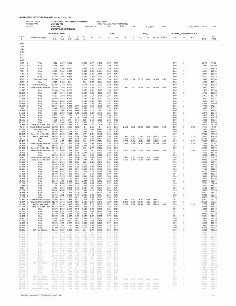
LIQUEFACTION POTENTIAL ANALYSIS (per Youd et al., 2001)
PROJECT NAME 11TH STREET EAST TRACY OVERHEAD FAULT INFOPROJECT NO. 2005-151-PSE GREAT VALLEY FAULT (REVERSE)CPT NO. CPT-12-002 FAULT M w = 6.7 MSF = 1.33 a max (g)= 0.465 VS30m(m/s)= 200.6 193.4
PERMANENT STRUCTURE
Depth qc fs v u v'(ft) (tsf) (tsf) (tsf) (tsf) (tsf)
0.4921.1481.8042.4613.1173.7734.4295.085 3 Clay 6.615 0.233 0.283 0.283 2.77 1.4835 0.99 0.299 1.00 1 99.89 99.895.741 3 Clay 8.748 0.42 0.32 0.32 2.81 1.4474 0.99 0.299 1.00 1 119.09 119.096.398 3 Clay 7.861 0.368 0.356 0.356 2.87 1.4139 0.99 0.298 1.00 1 111.35 111.357.054 3 Clay 8.426 0.432 0.393 0.393 2.91 1.381 0.99 0.298 1.00 1 116.34 116.347.71 3 Clay 8.862 0.5 0.429 0.429 2.95 1.3505 0.98 0.297 1.00 1 120.03 120.038.366 3 Clay 20.354 0.956 0.466 0.466 2.65 1.3205 0.98 0.297 1.00 1 202.23 202.239.022 4 Silty Clay to Clay 23.804 0.924 0.504 0.504 2.56 1.2911 0.98 0.297 2.560 1.29 30.73 3.091 94.982 0.16 1.00 1 136.00 136.009.678 3 Clay 8.115 0.454 0.54 0.54 3.07 1.2644 0.98 0.296 1.00 1 113.11 113.1110.335 4 Silty Clay to Clay 19.363 0.742 0.578 0.578 2.67 1.2373 0.98 0.296 1.00 1 195.56 195.5610.991 6 Sandy Silt to Clayey Silt 32.692 0.954 0.615 0.615 2.44 1.2121 0.98 0.295 2.440 1.21 39.63 2.483 98.398 0.17 1.00 1 149.57 149.5711.647 3 Clay 16.385 0.993 0.652 0.652 2.91 1.1879 0.98 0.295 1.00 1 176.38 176.3812.303 3 Clay 8.514 0.674 0.688 0.688 3.24 1.1653 0.97 0.294 1.00 1 117.03 117.0312.959 3 Clay 9.287 0.559 0.725 0.725 3.14 1.1429 0.97 0.294 1.00 1 123.73 123.7313.615 3 Clay 14.984 0.823 0.762 0.762 2.96 1.1213 0.97 0.294 1.00 1 166.91 166.9114.272 3 Clay 17.049 1.098 0.798 0.798 2.98 1.1011 0.97 0.293 1.00 1 180.74 180.7414.928 3 Clay 22.295 1.478 0.835 0.835 2.91 1.0811 0.97 0.293 1.00 1 213.99 213.9915.584 3 Clay 16.867 1.221 0.871 0.018 0.853 3.04 1.0716 0.97 0.299 1.00 1 179.61 179.6116.24 3 Clay 10.47 0.628 0.908 0.039 0.869 3.17 1.0633 0.97 0.305 1.00 1 133.12 133.1216.896 3 Clay 10.967 0.604 0.944 0.059 0.885 3.14 1.0552 0.96 0.311 1.00 1 137.07 137.0717.552 3 Clay 9.163 0.553 0.981 0.08 0.901 3.24 1.0471 0.96 0.317 1.00 1 122.48 122.4818.209 3 Clay 8.203 0.471 1.017 0.1 0.917 3.29 1.0392 0.96 0.322 1.00 1 114.25 114.2518.865 3 Clay 9.853 0.564 1.054 0.12 0.933 3.22 1.0314 0.96 0.328 1.00 1 128.19 128.1919.521 3 Clay 11.81 0.751 1.09 0.141 0.95 3.18 1.0233 0.96 0.332 1.00 1 143.65 143.6520.177 3 Clay 9.905 0.685 1.127 0.161 0.966 3.28 1.0157 0.96 0.337 1.00 1 128.60 128.6020.833 5 Clayey Silt to Silty Clay 27.182 1.053 1.165 0.182 0.983 2.74 1.0078 0.95 0.342 1.00 1 242.39 242.3921.49 6 Sandy Silt to Clayey Silt 38.923 1.181 1.202 0.202 1 2.56 1 0.95 0.346 2.560 1.00 38.92 3.091 120.294 0.24 1.00 1 (0.93) 174.47 75.4022.146 4 Silty Clay to Clay 24.359 1.074 1.24 0.223 1.017 2.83 0.9923 0.95 0.350 1.00 1 226.01 226.0122.802 3 Clay 15.285 0.92 1.276 0.243 1.033 3.1 0.9852 0.95 0.354 0.99 1 168.65 168.6523.458 5 Clayey Silt to Silty Clay 33.507 1.198 1.314 0.264 1.05 2.67 0.9778 0.95 0.358 0.99 1 276.13 276.1324.114 8 Sand to Silty Sand 116.45 1.312 1.354 0.284 1.069 1.92 0.9696 0.94 0.362 1.920 0.97 112.91 1.208 136.422 0.32 0.98 1 (1.14) 204.85 177.5824.77 9 Sand 172.07 1.05 1.394 0.305 1.09 1.63 0.9607 0.94 0.364 1.630 0.96 165.31 1.000 165.310 0.97 1 216.66 216.6625.427 9 Sand 110.5 0.63 1.435 0.325 1.11 1.77 0.9524 0.94 0.367 1.770 0.95 105.24 1.085 114.217 0.22 0.97 1 (0.77) 205.55 155.0826.083 6 Sandy Silt to Clayey Silt 30.539 0.662 1.473 0.346 1.127 2.59 0.9454 0.94 0.370 2.590 0.95 28.87 3.266 94.298 0.16 0.98 1 (0.56) 174.66 57.6626.739 3 Clay 11.581 0.543 1.509 0.366 1.143 3.19 0.939 0.94 0.373 0.97 1 142.58 142.5827.395 5 Clayey Silt to Silty Clay 30.295 1.191 1.547 0.387 1.16 2.77 0.9322 0.93 0.376 0.97 1 259.70 259.7028.051 6 Sandy Silt to Clayey Silt 57.716 1.899 1.584 0.407 1.177 2.5 0.9255 0.93 0.378 2.500 0.93 53.42 2.768 147.885 0.38 0.97 1 1.30 191.90 191.9028.707 3 Clay 15 0.812 1.621 0.428 1.193 3.15 0.9193 0.93 0.381 0.97 1 166.49 166.4929.364 3 Clay 12.748 0.845 1.658 0.448 1.21 3.28 0.9129 0.92 0.383 0.96 1 150.28 150.2830.02 6 Sandy Silt to Clayey Silt 77.733 2.611 1.695 0.468 1.227 2.43 0.9065 0.92 0.384 2.430 0.91 70.46 2.439 171.860 0.96 1 201.73 201.7330.676 5 Clayey Silt to Silty Clay 79.279 3.374 1.733 0.489 1.244 2.5 0.9002 0.92 0.386 2.500 0.90 71.36 2.768 197.567 0.96 1 202.99 202.9931.332 3 Clay 30.617 2.014 1.769 0.509 1.26 2.95 0.8943 0.91 0.388 0.95 1 260.77 260.7731.988 3 Clay 17.635 1.203 1.806 0.53 1.276 3.17 0.8885 0.91 0.389 0.95 1 184.38 184.3832.644 3 Clay 10.107 0.705 1.842 0.55 1.292 3.43 0.8828 0.91 0.390 0.95 1 129.82 129.8233.301 3 Clay 15.772 1.007 1.879 0.571 1.308 3.21 0.8772 0.90 0.392 0.95 1 171.89 171.8933.957 3 Clay 44.008 2.316 1.915 0.591 1.324 2.78 0.8716 0.90 0.392 0.95 1 327.63 327.6334.613 3 Clay 18.538 1.312 1.952 0.612 1.34 3.19 0.8661 0.89 0.393 0.94 1 190.18 190.1835.269 3 Clay 13.926 0.974 1.989 0.632 1.356 3.31 0.8607 0.89 0.394 0.94 1 158.83 158.8335.925 3 Clay 13.428 0.983 2.025 0.653 1.372 3.34 0.8554 0.88 0.394 0.94 1 155.36 155.3636.581 3 Clay 25.548 1.46 2.062 0.673 1.388 3.01 0.8501 0.88 0.395 0.94 1 232.94 232.9437.238 3 Clay 29.932 1.855 2.098 0.694 1.405 2.98 0.8445 0.87 0.394 0.93 1 257.33 257.3337.894 3 Clay 17.76 1.318 2.135 0.714 1.421 3.24 0.8394 0.87 0.395 0.93 1 185.37 185.3738.55 3 Clay 9.453 0.862 2.171 0.735 1.437 3.6 0.8343 0.86 0.394 0.93 1 124.65 124.6539.206 3 Clay 21.361 1.606 2.208 0.755 1.453 3.18 0.8292 0.86 0.394 0.93 1 208.28 208.2839.862 3 Clay 31.473 2.05 2.244 0.776 1.469 3 0.8243 0.85 0.393 0.93 1 265.72 265.7240.518 3 Clay 30.752 2.01 2.281 0.796 1.485 3.01 0.8194 0.85 0.393 0.92 1 262.16 262.1641.175 3 Clay 45.653 3.127 2.318 0.817 1.501 2.89 0.8145 0.84 0.392 0.92 1 335.56 335.5641.831 6 Sandy Silt to Clayey Silt 94.403 3.016 2.355 0.837 1.518 2.42 0.8094 0.83 0.391 2.420 0.81 76.41 2.396 183.072 0.91 1 219.12 219.1242.487 7 Silty Sand to Sandy Silt 113.74 2.642 2.394 0.857 1.536 2.27 0.8041 0.83 0.390 2.270 0.80 91.45 1.856 169.746 0.90 1 225.21 225.2143.143 8 Sand to Silty Sand 120.72 2.134 2.433 0.878 1.555 2.17 0.7985 0.82 0.389 2.170 0.80 96.40 1.596 153.896 0.42 0.90 1 (1.29) 227.72 227.7243.799 5 Clayey Silt to Silty Clay 45.279 1.681 2.471 0.898 1.573 2.73 0.7934 0.82 0.387 0.91 1 333.85 333.8544.455 3 Clay 17.376 1.219 2.508 0.919 1.589 3.29 0.7888 0.81 0.386 0.91 1 183.13 183.1345.112 3 Clay 16.504 1.292 2.544 0.939 1.605 3.34 0.7843 0.80 0.384 0.91 1 177.32 177.3245.768 3 Clay 42.333 2.505 2.581 0.96 1.621 2.9 0.7799 0.80 0.383 0.91 1 320.19 320.1946.424 3 Clay 37.528 2.39 2.617 0.98 1.637 2.97 0.7755 0.79 0.381 0.91 1 296.74 296.7447.08 3 Clay 26.601 1.77 2.654 1.001 1.653 3.11 0.7711 0.78 0.380 0.90 1 239.19 239.1947.736 3 Clay 18.18 1.385 2.69 1.021 1.669 3.31 0.7668 0.78 0.378 0.90 1 188.30 188.3048.392 3 Clay 14.543 0.79 2.727 1.042 1.685 3.33 0.7626 0.77 0.376 0.90 1 163.75 163.7549.049 3 Clay 13.926 0.852 2.763 1.062 1.701 3.38 0.7584 0.76 0.374 0.90 1 159.55 159.5549.705 3 Clay 40.703 2.878 2.8 1.083 1.717 2.99 0.7542 0.76 0.372 0.90 1 312.55 312.5550.361 11 Sitff Fine-Grained 60.616 3.386 2.843 1.103 1.74 2.78 0.7483 0.75 0.370 0.90 1 400.85 400.8551.017 3 Clay 29.688 2.009 2.879 1.124 1.756 3.1 0.7442 0.74 0.368 0.89 1 255.98 255.9851.673 3 Clay 20.115 1.432 2.916 1.144 1.772 3.28 0.7402 0.74 0.366 0.89 1 200.86 200.8652.329 3 Clay 19.021 1.158 2.952 1.165 1.788 3.26 0.7363 0.73 0.364 0.89 1 194.29 194.2952.986 3 Clay 22.217 1.463 2.989 1.185 1.804 3.22 0.7324 0.72 0.362 0.89 1 214.17 214.1753.642 3 Clay 26.751 1.542 3.026 1.206 1.82 3.11 0.7285 0.72 0.360 0.89 1 240.54 240.5454.298 3 Clay 31.369 1.969 3.062 1.226 1.836 3.07 0.7246 0.71 0.358 0.89 1 265.67 265.6754.954 3 Clay 21.148 1.443 3.099 1.246 1.852 3.26 0.7208 0.70 0.356 0.88 1 207.48 207.4855.61 3 Clay 18.818 1.284 3.135 1.267 1.868 3.32 0.7171 0.70 0.354 0.88 1 193.01 193.0156.266 3 Clay 26.451 1.82 3.172 1.287 1.884 3.18 0.7134 0.69 0.352 0.88 1 238.68 238.6856.923 3 Clay 35.774 2.553 3.208 1.308 1.9 3.08 0.7097 0.69 0.350 0.88 1 288.14 288.1457.579 3 Clay 21.729 1.582 3.245 1.328 1.916 3.29 0.706 0.68 0.348 0.88 1 210.96 210.9658.235 3 Clay 14.05 1.051 3.281 1.349 1.933 3.5 0.7022 0.67 0.346 0.88 1 160.69 160.6958.891 3 Clay 23.197 1.698 3.318 1.369 1.949 3.27 0.6986 0.67 0.344 0.88 1 219.96 219.9659.547 11 Sitff Fine-Grained 60.927 3.698 3.361 1.39 1.971 2.85 0.6938 0.66 0.342 0.87 1 402.14 402.1460.203 3 Clay 32.059 2.471 3.397 1.41 1.987 3.16 0.6903 0.66 0.340 0.87 1 268.73 268.7360.86 3 Clay 24.982 2.014 3.434 1.431 2.003 3.28 0.6869 0.65 0.338 0.87 1 229.90 229.9061.516 3 Clay 17.469 1.4 3.47 1.451 2.019 3.44 0.6834 0.65 0.336 0.87 1 183.85 183.8562.172 3 Clay 22.201 1.756 3.507 1.472 2.035 3.33 0.6801 0.64 0.335 0.87 1 213.99 213.9962.828 3 Clay 26.928 2.27 3.543 1.492 2.051 3.27 0.6767 0.64 0.333 0.87 1 241.44 241.4463.484 11 Sitff Fine-Grained 92.852 5.304 3.586 1.513 2.074 2.71 0.672 0.63 0.331 0.86 1 523.90 523.9064.14 11 Sitff Fine-Grained 124.48 6.256 3.629 1.533 2.096 2.58 0.6675 0.63 0.329 2.580 0.67 83.08 3.206 266.405 0.86 1 247.83 247.8364.797 3 Clay 52.75 4.13 3.666 1.554 2.112 3 0.6643 0.62 0.327 0.86 1 367.22 367.2265.453 8 Sand to Silty Sand 210.2 3.069 3.705 1.574 2.131 2.03 0.6605 0.62 0.325 2.030 0.66 138.83 1.341 186.196 0.80 1 266.50 266.5066.109 9 Sand 284.48 2.685 3.746 1.594 2.152 1.81 0.6563 0.61 0.323 1.810 0.66 186.71 1.114 208.001 0.76 1 277.93 277.9366.765 10 Gravelly Sand to Sand 375.97 3.156 3.788 1.615 2.173 1.69 0.6522 0.61 0.322 1.690 0.65 245.22 1.031 252.842 0.73 1 288.93 288.93
CQ qc1N KC (qc1N)cs CRR7.5 K K F.S.Vs
(m/s)Vs,liq
(m/s)
CPT RESULT INPUT CSR CRR 7.5 F.S.=(CRR 7.5 /CSR)*MSF*K *K
Soil Behavior Type Ic* CN* d CSR Ic
3/21/2014 Liquefaction CPT-12-002 (YOUD with VS_NEW) 1 of 1
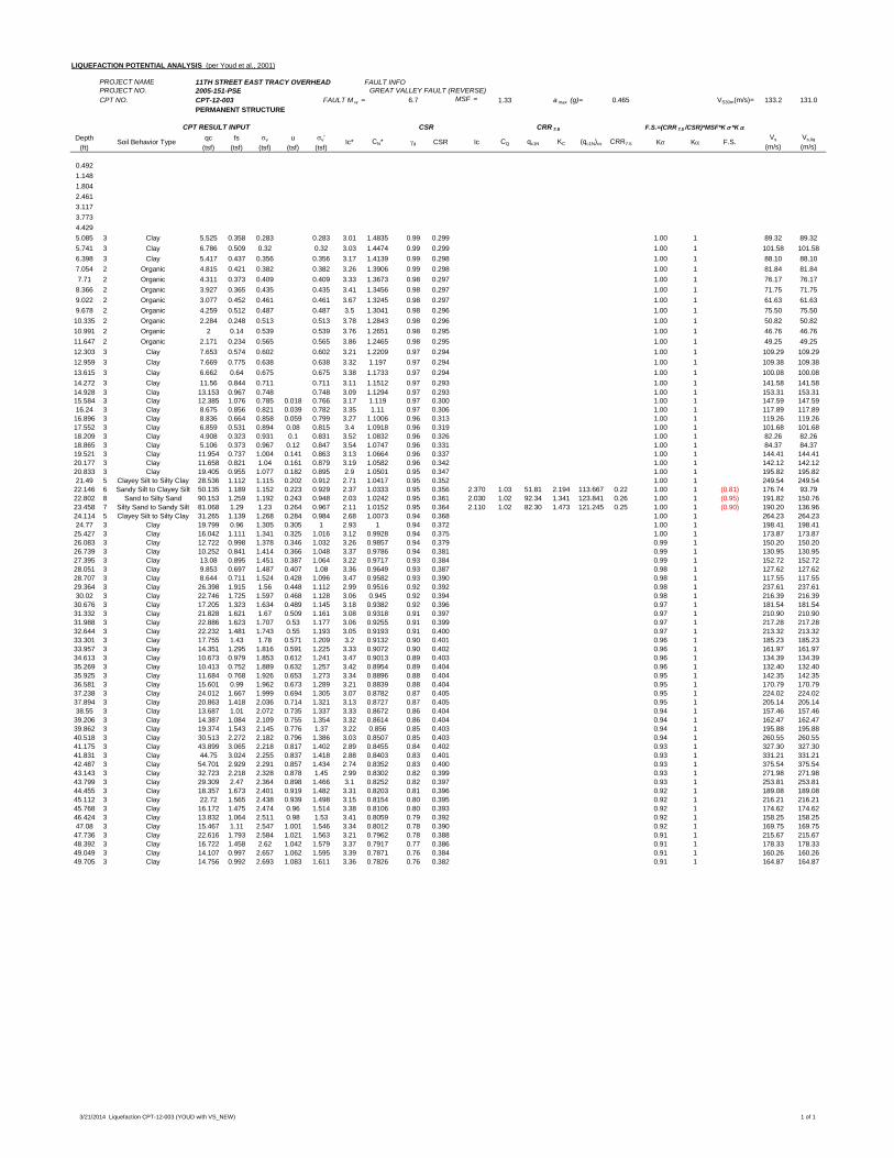
LIQUEFACTION POTENTIAL ANALYSIS (per Youd et al., 2001)
PROJECT NAME 11TH STREET EAST TRACY OVERHEAD FAULT INFOPROJECT NO. 2005-151-PSE GREAT VALLEY FAULT (REVERSE)CPT NO. CPT-12-003 FAULT M w = 6.7 MSF = 1.33 a max (g)= 0.465 VS30m(m/s)= 133.2 131.0
PERMANENT STRUCTURE
Depth qc fs v u v'(ft) (tsf) (tsf) (tsf) (tsf) (tsf)
0.4921.1481.8042.4613.1173.7734.4295.085 3 Clay 5.525 0.358 0.283 0.283 3.01 1.4835 0.99 0.299 1.00 1 89.32 89.325.741 3 Clay 6.786 0.509 0.32 0.32 3.03 1.4474 0.99 0.299 1.00 1 101.58 101.586.398 3 Clay 5.417 0.437 0.356 0.356 3.17 1.4139 0.99 0.298 1.00 1 88.10 88.107.054 2 Organic 4.815 0.421 0.382 0.382 3.26 1.3906 0.99 0.298 1.00 1 81.84 81.847.71 2 Organic 4.311 0.373 0.409 0.409 3.33 1.3673 0.98 0.297 1.00 1 76.17 76.178.366 2 Organic 3.927 0.365 0.435 0.435 3.41 1.3456 0.98 0.297 1.00 1 71.75 71.759.022 2 Organic 3.077 0.452 0.461 0.461 3.67 1.3245 0.98 0.297 1.00 1 61.63 61.639.678 2 Organic 4.259 0.512 0.487 0.487 3.5 1.3041 0.98 0.296 1.00 1 75.50 75.5010.335 2 Organic 2.284 0.248 0.513 0.513 3.78 1.2843 0.98 0.296 1.00 1 50.82 50.8210.991 2 Organic 2 0.14 0.539 0.539 3.76 1.2651 0.98 0.295 1.00 1 46.76 46.7611.647 2 Organic 2.171 0.234 0.565 0.565 3.86 1.2465 0.98 0.295 1.00 1 49.25 49.2512.303 3 Clay 7.653 0.574 0.602 0.602 3.21 1.2209 0.97 0.294 1.00 1 109.29 109.2912.959 3 Clay 7.669 0.775 0.638 0.638 3.32 1.197 0.97 0.294 1.00 1 109.38 109.3813.615 3 Clay 6.662 0.64 0.675 0.675 3.38 1.1733 0.97 0.294 1.00 1 100.08 100.0814.272 3 Clay 11.56 0.844 0.711 0.711 3.11 1.1512 0.97 0.293 1.00 1 141.58 141.5814.928 3 Clay 13.153 0.967 0.748 0.748 3.09 1.1294 0.97 0.293 1.00 1 153.31 153.3115.584 3 Clay 12.385 1.076 0.785 0.018 0.766 3.17 1.119 0.97 0.300 1.00 1 147.59 147.5916.24 3 Clay 8.675 0.856 0.821 0.039 0.782 3.35 1.11 0.97 0.306 1.00 1 117.89 117.8916.896 3 Clay 8.836 0.664 0.858 0.059 0.799 3.27 1.1006 0.96 0.313 1.00 1 119.26 119.2617.552 3 Clay 6.859 0.531 0.894 0.08 0.815 3.4 1.0918 0.96 0.319 1.00 1 101.68 101.6818.209 3 Clay 4.908 0.323 0.931 0.1 0.831 3.52 1.0832 0.96 0.326 1.00 1 82.26 82.2618.865 3 Clay 5.106 0.373 0.967 0.12 0.847 3.54 1.0747 0.96 0.331 1.00 1 84.37 84.3719.521 3 Clay 11.954 0.737 1.004 0.141 0.863 3.13 1.0664 0.96 0.337 1.00 1 144.41 144.4120.177 3 Clay 11.658 0.821 1.04 0.161 0.879 3.19 1.0582 0.96 0.342 1.00 1 142.12 142.1220.833 3 Clay 19.405 0.955 1.077 0.182 0.895 2.9 1.0501 0.95 0.347 1.00 1 195.82 195.8221.49 5 Clayey Silt to Silty Clay 28.536 1.112 1.115 0.202 0.912 2.71 1.0417 0.95 0.352 1.00 1 249.54 249.5422.146 6 Sandy Silt to Clayey Silt 50.135 1.189 1.152 0.223 0.929 2.37 1.0333 0.95 0.356 2.370 1.03 51.81 2.194 113.667 0.22 1.00 1 (0.81) 176.74 93.7922.802 8 Sand to Silty Sand 90.153 1.259 1.192 0.243 0.948 2.03 1.0242 0.95 0.361 2.030 1.02 92.34 1.341 123.841 0.26 1.00 1 (0.95) 191.82 150.7623.458 7 Silty Sand to Sandy Silt 81.068 1.29 1.23 0.264 0.967 2.11 1.0152 0.95 0.364 2.110 1.02 82.30 1.473 121.245 0.25 1.00 1 (0.90) 190.20 136.9624.114 5 Clayey Silt to Silty Clay 31.265 1.139 1.268 0.284 0.984 2.68 1.0073 0.94 0.368 1.00 1 264.23 264.2324.77 3 Clay 19.799 0.96 1.305 0.305 1 2.93 1 0.94 0.372 1.00 1 198.41 198.4125.427 3 Clay 16.042 1.111 1.341 0.325 1.016 3.12 0.9928 0.94 0.375 1.00 1 173.87 173.8726.083 3 Clay 12.722 0.998 1.378 0.346 1.032 3.26 0.9857 0.94 0.379 0.99 1 150.20 150.2026.739 3 Clay 10.252 0.841 1.414 0.366 1.048 3.37 0.9786 0.94 0.381 0.99 1 130.95 130.9527.395 3 Clay 13.08 0.895 1.451 0.387 1.064 3.22 0.9717 0.93 0.384 0.99 1 152.72 152.7228.051 3 Clay 9.853 0.697 1.487 0.407 1.08 3.36 0.9649 0.93 0.387 0.98 1 127.62 127.6228.707 3 Clay 8.644 0.711 1.524 0.428 1.096 3.47 0.9582 0.93 0.390 0.98 1 117.55 117.5529.364 3 Clay 26.398 1.915 1.56 0.448 1.112 2.99 0.9516 0.92 0.392 0.98 1 237.61 237.6130.02 3 Clay 22.746 1.725 1.597 0.468 1.128 3.06 0.945 0.92 0.394 0.98 1 216.39 216.3930.676 3 Clay 17.205 1.323 1.634 0.489 1.145 3.18 0.9382 0.92 0.396 0.97 1 181.54 181.5431.332 3 Clay 21.828 1.621 1.67 0.509 1.161 3.08 0.9318 0.91 0.397 0.97 1 210.90 210.9031.988 3 Clay 22.886 1.623 1.707 0.53 1.177 3.06 0.9255 0.91 0.399 0.97 1 217.28 217.2832.644 3 Clay 22.232 1.481 1.743 0.55 1.193 3.05 0.9193 0.91 0.400 0.97 1 213.32 213.3233.301 3 Clay 17.755 1.43 1.78 0.571 1.209 3.2 0.9132 0.90 0.401 0.96 1 185.23 185.2333.957 3 Clay 14.351 1.295 1.816 0.591 1.225 3.33 0.9072 0.90 0.402 0.96 1 161.97 161.9734.613 3 Clay 10.673 0.979 1.853 0.612 1.241 3.47 0.9013 0.89 0.403 0.96 1 134.39 134.3935.269 3 Clay 10.413 0.752 1.889 0.632 1.257 3.42 0.8954 0.89 0.404 0.96 1 132.40 132.4035.925 3 Clay 11.684 0.768 1.926 0.653 1.273 3.34 0.8896 0.88 0.404 0.95 1 142.35 142.3536.581 3 Clay 15.601 0.99 1.962 0.673 1.289 3.21 0.8839 0.88 0.404 0.95 1 170.79 170.7937.238 3 Clay 24.012 1.667 1.999 0.694 1.305 3.07 0.8782 0.87 0.405 0.95 1 224.02 224.0237.894 3 Clay 20.863 1.418 2.036 0.714 1.321 3.13 0.8727 0.87 0.405 0.95 1 205.14 205.1438.55 3 Clay 13.687 1.01 2.072 0.735 1.337 3.33 0.8672 0.86 0.404 0.94 1 157.46 157.4639.206 3 Clay 14.387 1.084 2.109 0.755 1.354 3.32 0.8614 0.86 0.404 0.94 1 162.47 162.4739.862 3 Clay 19.374 1.543 2.145 0.776 1.37 3.22 0.856 0.85 0.403 0.94 1 195.88 195.8840.518 3 Clay 30.513 2.272 2.182 0.796 1.386 3.03 0.8507 0.85 0.403 0.94 1 260.55 260.5541.175 3 Clay 43.899 3.065 2.218 0.817 1.402 2.89 0.8455 0.84 0.402 0.93 1 327.30 327.3041.831 3 Clay 44.75 3.024 2.255 0.837 1.418 2.88 0.8403 0.83 0.401 0.93 1 331.21 331.2142.487 3 Clay 54.701 2.929 2.291 0.857 1.434 2.74 0.8352 0.83 0.400 0.93 1 375.54 375.5443.143 3 Clay 32.723 2.218 2.328 0.878 1.45 2.99 0.8302 0.82 0.399 0.93 1 271.98 271.9843.799 3 Clay 29.309 2.47 2.364 0.898 1.466 3.1 0.8252 0.82 0.397 0.93 1 253.81 253.8144.455 3 Clay 18.357 1.673 2.401 0.919 1.482 3.31 0.8203 0.81 0.396 0.92 1 189.08 189.0845.112 3 Clay 22.72 1.565 2.438 0.939 1.498 3.15 0.8154 0.80 0.395 0.92 1 216.21 216.2145.768 3 Clay 16.172 1.475 2.474 0.96 1.514 3.38 0.8106 0.80 0.393 0.92 1 174.62 174.6246.424 3 Clay 13.832 1.064 2.511 0.98 1.53 3.41 0.8059 0.79 0.392 0.92 1 158.25 158.2547.08 3 Clay 15.467 1.11 2.547 1.001 1.546 3.34 0.8012 0.78 0.390 0.92 1 169.75 169.7547.736 3 Clay 22.616 1.793 2.584 1.021 1.563 3.21 0.7962 0.78 0.388 0.91 1 215.67 215.6748.392 3 Clay 16.722 1.458 2.62 1.042 1.579 3.37 0.7917 0.77 0.386 0.91 1 178.33 178.3349.049 3 Clay 14.107 0.997 2.657 1.062 1.595 3.39 0.7871 0.76 0.384 0.91 1 160.26 160.2649.705 3 Clay 14.756 0.992 2.693 1.083 1.611 3.36 0.7826 0.76 0.382 0.91 1 164.87 164.87
CQ qc1N KC (qc1N)cs CRR7.5 K K F.S.Vs
(m/s)Vs,liq
(m/s)
CPT RESULT INPUT CSR CRR 7.5 F.S.=(CRR 7.5 /CSR)*MSF*K *K
Soil Behavior Type Ic* CN* d CSR Ic
3/21/2014 Liquefaction CPT-12-003 (YOUD with VS_NEW) 1 of 1
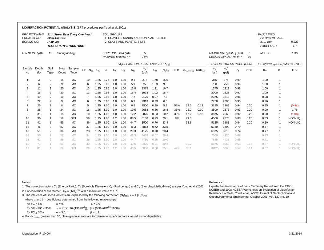
LIQUEFACTION POTENTIAL ANALYSIS (SPT procedures per Youd et al, 2001)
PROJECT NAME 11th Street East Tracy Overhead SOIL GROUPS FAULT INFOPROJECT NO. 2005-151-PSE 1. GRAVELS, SANDS AND NONPLASTIC SILTS HAYWARD FAULTBORING NO. R-10-004 2. CLAYS AND PLASTIC SILTS a max (g)= 0.227
TEMPORARY STRUCTURE FAULT M w = 6.7
GW DEPTH (ft)= 15 (during drilling) BOREHOLE DIA (in)= 5 MAJOR CUT(-)/FILL(+) (ft) 0 MSF = 1.33HAMMER ENERGY = 75% DESIGN GW DEPTH (ft)= 10
Sample Depth Soil Blow Sampler v' v v'No (ft) Type Count Type (psf) (psf) (psf)
1 3 2 15 MC 10 1.25 0.75 1.0 1.00 9.1 375 1.70 15.5 375 375 0.99 1.00 12 6 2 9 MC 6 1.25 0.80 1.0 1.00 5.9 750 1.63 9.6 750 750 0.99 1.00 13 11 2 20 MC 13 1.25 0.85 1.0 1.00 13.8 1375 1.21 16.7 1375 1313 0.98 1.00 14 16 2 20 MC 13 1.25 0.95 1.0 1.00 15.4 1938 1.02 15.7 2000 1625 0.97 1.00 15 19 2 10 MC 7 1.25 0.95 1.0 1.00 7.7 2125 0.97 7.5 2375 1813 0.96 0.98 16 22 2 9 MC 6 1.25 0.95 1.0 1.00 6.9 2313 0.93 6.5 2750 2000 0.95 0.96 17 25 1 8 MC 5 1.25 1.00 1.0 1.00 6.5 2500 0.89 5.8 51% 12.0 0.13 3125 2188 0.94 0.20 0.95 1 (0.84)8 28 1 24 MC 16 1.25 1.00 1.0 1.00 19.5 2688 0.86 16.8 35% 25.2 0.30 3500 2375 0.93 0.20 0.90 1 1.769 31 1 15 MC 10 1.25 1.00 1.0 1.00 12.2 2875 0.83 10.2 35% 17.2 0.18 3875 2563 0.92 0.20 0.90 1 (1.08)10 36 1 59 SPT 59 1.25 1.00 1.2 1.00 88.5 3188 0.79 70.1 8% 71.3 4500 2875 0.88 0.20 0.83 1 NON-LIQ.11 41 1 55 MC 36 1.25 1.00 1.0 1.00 44.7 3500 0.76 33.8 33.8 5125 3188 0.84 0.20 0.80 1 NON-LIQ.12 46 2 57 MC 37 1.25 1.00 1.0 1.00 46.3 3813 0.72 33.5 5750 3500 0.79 0.77 113 51 2 36 MC 23 1.25 1.00 1.0 1.00 29.3 4125 0.70 20.4 6375 3813 0.74 0.77 114 56 2 52 MC 34 1.25 1.00 1.0 1.00 42.3 4438 0.67 28.4 7000 4125 0.69 0.73 115 61 2 55 MC 36 1.25 1.00 1.0 1.00 44.7 4750 0.65 29.0 7625 4438 0.65 0.71 116 71 1 61 MC 40 1.25 1.00 1.0 1.00 49.6 5375 0.61 30.2 30.2 8875 5063 0.59 0.15 0.67 1 NON-LIQ.17 81 1 29 SPT 29 1.25 1.00 1.2 1.00 43.5 6000 0.58 25.1 42% 35.1 10125 5688 0.54 0.14 0.67 1 NON-LIQ.
Notes: Reference: 1. The correction factors CE (Energy Ratio), CB (Borehole Diameter), CR (Rod Length) and CS (Sampling Method-liner) are per Youd et al. (2001).2. For correction of overburden, CN = (1/v')
0.5 with a maximum value of 1.7. 3. The influence of Fines Contents are expressed by the following correction: (N1)60cs = + (N1)60
where and = coefficients determined from the following relationships for FC < 5% = 0, = 1.0 for 5% < FC < 35% = exp(1.76-(190/FC2)), = (0.99+(FC1.5/1000)) for FC > 35% = 5.0, = 1.24. For (N1)60,cs greater than 30, clean granular soils are too dense to liquefy and are classed as non-liquefiable.
Liquefaction Resistance of Soils: Summary Report from the 1996 NCEER and 1998 NCEER Workshops on Evaluation of Liquefaction Resistance of Soils, Youd, et al., ASCE Journal of Geotechnical and Geoenvironmental Engineering, October 2001, Vol. 127 No. 10
K K F.S.CSR
LIQUEFACTION RESISTANCE (CRR 7.5 ) CYCLIC STRESS RATIO (CSR) F.S.=(CRR 7.5 /CSR)*MSF*K *K
SPT-Neq. CE CR CS CB N60 CN (N1)60 F.C. (N1)60, CS CRR7.5 rd
Liquefaction_R-10-004 3/21/2014
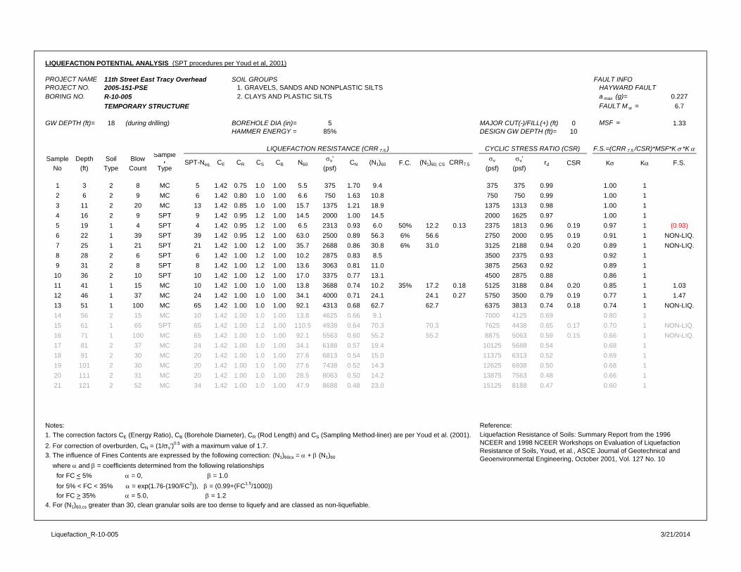
LIQUEFACTION POTENTIAL ANALYSIS (SPT procedures per Youd et al, 2001)
PROJECT NAME 11th Street East Tracy Overhead SOIL GROUPS FAULT INFOPROJECT NO. 2005-151-PSE 1. GRAVELS, SANDS AND NONPLASTIC SILTS HAYWARD FAULTBORING NO. R-10-005 2. CLAYS AND PLASTIC SILTS a max (g)= 0.227
TEMPORARY STRUCTURE FAULT M w = 6.7
GW DEPTH (ft)= 18 (during drilling) BOREHOLE DIA (in)= 5 MAJOR CUT(-)/FILL(+) (ft) 0 MSF = 1.33HAMMER ENERGY = 85% DESIGN GW DEPTH (ft)= 10
Sample Depth Soil Blow Sampler v' v v'
No (ft) Type Count Type (psf) (psf) (psf)
1 3 2 8 MC 5 1.42 0.75 1.0 1.00 5.5 375 1.70 9.4 375 375 0.99 1.00 12 6 2 9 MC 6 1.42 0.80 1.0 1.00 6.6 750 1.63 10.8 750 750 0.99 1.00 13 11 2 20 MC 13 1.42 0.85 1.0 1.00 15.7 1375 1.21 18.9 1375 1313 0.98 1.00 14 16 2 9 SPT 9 1.42 0.95 1.2 1.00 14.5 2000 1.00 14.5 2000 1625 0.97 1.00 15 19 1 4 SPT 4 1.42 0.95 1.2 1.00 6.5 2313 0.93 6.0 50% 12.2 0.13 2375 1813 0.96 0.19 0.97 1 (0.93)6 22 1 39 SPT 39 1.42 0.95 1.2 1.00 63.0 2500 0.89 56.3 6% 56.6 2750 2000 0.95 0.19 0.91 1 NON-LIQ.7 25 1 21 SPT 21 1.42 1.00 1.2 1.00 35.7 2688 0.86 30.8 6% 31.0 3125 2188 0.94 0.20 0.89 1 NON-LIQ.8 28 2 6 SPT 6 1.42 1.00 1.2 1.00 10.2 2875 0.83 8.5 3500 2375 0.93 0.92 19 31 2 8 SPT 8 1.42 1.00 1.2 1.00 13.6 3063 0.81 11.0 3875 2563 0.92 0.89 1
10 36 2 10 SPT 10 1.42 1.00 1.2 1.00 17.0 3375 0.77 13.1 4500 2875 0.88 0.86 111 41 1 15 MC 10 1.42 1.00 1.0 1.00 13.8 3688 0.74 10.2 35% 17.2 0.18 5125 3188 0.84 0.20 0.85 1 1.0312 46 1 37 MC 24 1.42 1.00 1.0 1.00 34.1 4000 0.71 24.1 24.1 0.27 5750 3500 0.79 0.19 0.77 1 1.4713 51 1 100 MC 65 1.42 1.00 1.0 1.00 92.1 4313 0.68 62.7 62.7 6375 3813 0.74 0.18 0.74 1 NON-LIQ.14 56 2 15 MC 10 1.42 1.00 1.0 1.00 13.8 4625 0.66 9.1 7000 4125 0.69 0.80 115 61 1 65 SPT 65 1.42 1.00 1.2 1.00 110.5 4938 0.64 70.3 70.3 7625 4438 0.65 0.17 0.70 1 NON-LIQ.16 71 1 100 MC 65 1.42 1.00 1.0 1.00 92.1 5563 0.60 55.2 55.2 8875 5063 0.59 0.15 0.66 1 NON-LIQ.17 81 2 37 MC 24 1.42 1.00 1.0 1.00 34.1 6188 0.57 19.4 10125 5688 0.54 0.68 118 91 2 30 MC 20 1.42 1.00 1.0 1.00 27.6 6813 0.54 15.0 11375 6313 0.52 0.69 119 101 2 30 MC 20 1.42 1.00 1.0 1.00 27.6 7438 0.52 14.3 12625 6938 0.50 0.68 120 111 2 31 MC 20 1.42 1.00 1.0 1.00 28.5 8063 0.50 14.2 13875 7563 0.48 0.66 121 121 2 52 MC 34 1.42 1.00 1.0 1.00 47.9 8688 0.48 23.0 15125 8188 0.47 0.60 1
Notes: Reference: 1. The correction factors CE (Energy Ratio), CB (Borehole Diameter), CR (Rod Length) and CS (Sampling Method-liner) are per Youd et al. (2001).2. For correction of overburden, CN = (1/v')
0.5 with a maximum value of 1.7. 3. The influence of Fines Contents are expressed by the following correction: (N1)60cs = + (N1)60
where and = coefficients determined from the following relationships for FC < 5% = 0, = 1.0 for 5% < FC < 35% = exp(1.76-(190/FC2)), = (0.99+(FC1.5/1000)) for FC > 35% = 5.0, = 1.24. For (N1)60,cs greater than 30, clean granular soils are too dense to liquefy and are classed as non-liquefiable.
Liquefaction Resistance of Soils: Summary Report from the 1996 NCEER and 1998 NCEER Workshops on Evaluation of Liquefaction Resistance of Soils, Youd, et al., ASCE Journal of Geotechnical and Geoenvironmental Engineering, October 2001, Vol. 127 No. 10
K K F.S.CSR
LIQUEFACTION RESISTANCE (CRR 7.5 ) CYCLIC STRESS RATIO (CSR) F.S.=(CRR 7.5 /CSR)*MSF*K *K
SPT-Neq. CE CR CS CB N60 CN (N1)60 F.C. (N1)60, CS CRR7.5 rd
Liquefaction_R-10-005 3/21/2014
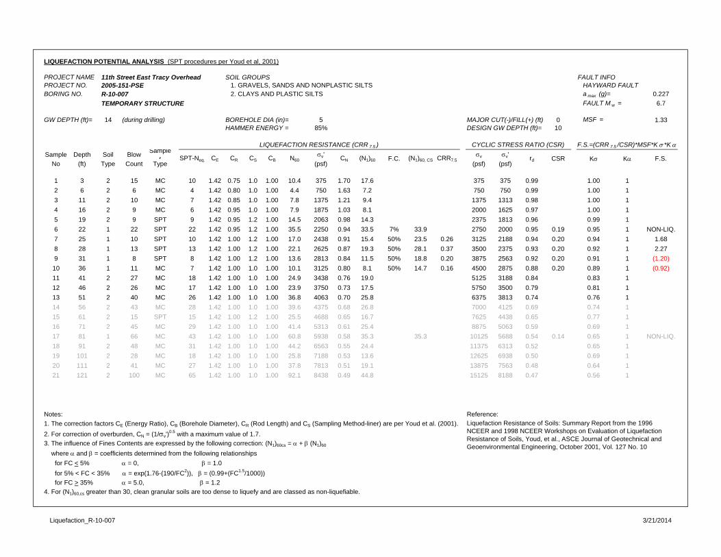
LIQUEFACTION POTENTIAL ANALYSIS (SPT procedures per Youd et al, 2001)
PROJECT NAME 11th Street East Tracy Overhead SOIL GROUPS FAULT INFOPROJECT NO. 2005-151-PSE 1. GRAVELS, SANDS AND NONPLASTIC SILTS HAYWARD FAULTBORING NO. R-10-007 2. CLAYS AND PLASTIC SILTS a max (g)= 0.227
TEMPORARY STRUCTURE FAULT M w = 6.7
GW DEPTH (ft)= 14 (during drilling) BOREHOLE DIA (in)= 5 MAJOR CUT(-)/FILL(+) (ft) 0 MSF = 1.33HAMMER ENERGY = 85% DESIGN GW DEPTH (ft)= 10
Sample Depth Soil Blow Sampler v' v v'
No (ft) Type Count Type (psf) (psf) (psf)
1 3 2 15 MC 10 1.42 0.75 1.0 1.00 10.4 375 1.70 17.6 375 375 0.99 1.00 12 6 2 6 MC 4 1.42 0.80 1.0 1.00 4.4 750 1.63 7.2 750 750 0.99 1.00 13 11 2 10 MC 7 1.42 0.85 1.0 1.00 7.8 1375 1.21 9.4 1375 1313 0.98 1.00 14 16 2 9 MC 6 1.42 0.95 1.0 1.00 7.9 1875 1.03 8.1 2000 1625 0.97 1.00 15 19 2 9 SPT 9 1.42 0.95 1.2 1.00 14.5 2063 0.98 14.3 2375 1813 0.96 0.99 16 22 1 22 SPT 22 1.42 0.95 1.2 1.00 35.5 2250 0.94 33.5 7% 33.9 2750 2000 0.95 0.19 0.95 1 NON-LIQ.7 25 1 10 SPT 10 1.42 1.00 1.2 1.00 17.0 2438 0.91 15.4 50% 23.5 0.26 3125 2188 0.94 0.20 0.94 1 1.688 28 1 13 SPT 13 1.42 1.00 1.2 1.00 22.1 2625 0.87 19.3 50% 28.1 0.37 3500 2375 0.93 0.20 0.92 1 2.279 31 1 8 SPT 8 1.42 1.00 1.2 1.00 13.6 2813 0.84 11.5 50% 18.8 0.20 3875 2563 0.92 0.20 0.91 1 (1.20)
10 36 1 11 MC 7 1.42 1.00 1.0 1.00 10.1 3125 0.80 8.1 50% 14.7 0.16 4500 2875 0.88 0.20 0.89 1 (0.92)11 41 2 27 MC 18 1.42 1.00 1.0 1.00 24.9 3438 0.76 19.0 5125 3188 0.84 0.83 112 46 2 26 MC 17 1.42 1.00 1.0 1.00 23.9 3750 0.73 17.5 5750 3500 0.79 0.81 113 51 2 40 MC 26 1.42 1.00 1.0 1.00 36.8 4063 0.70 25.8 6375 3813 0.74 0.76 114 56 2 43 MC 28 1.42 1.00 1.0 1.00 39.6 4375 0.68 26.8 7000 4125 0.69 0.74 115 61 2 15 SPT 15 1.42 1.00 1.2 1.00 25.5 4688 0.65 16.7 7625 4438 0.65 0.77 116 71 2 45 MC 29 1.42 1.00 1.0 1.00 41.4 5313 0.61 25.4 8875 5063 0.59 0.69 117 81 1 66 MC 43 1.42 1.00 1.0 1.00 60.8 5938 0.58 35.3 35.3 10125 5688 0.54 0.14 0.65 1 NON-LIQ.18 91 2 48 MC 31 1.42 1.00 1.0 1.00 44.2 6563 0.55 24.4 11375 6313 0.52 0.65 119 101 2 28 MC 18 1.42 1.00 1.0 1.00 25.8 7188 0.53 13.6 12625 6938 0.50 0.69 120 111 2 41 MC 27 1.42 1.00 1.0 1.00 37.8 7813 0.51 19.1 13875 7563 0.48 0.64 121 121 2 100 MC 65 1.42 1.00 1.0 1.00 92.1 8438 0.49 44.8 15125 8188 0.47 0.56 1
Notes: Reference: 1. The correction factors CE (Energy Ratio), CB (Borehole Diameter), CR (Rod Length) and CS (Sampling Method-liner) are per Youd et al. (2001).2. For correction of overburden, CN = (1/v')
0.5 with a maximum value of 1.7. 3. The influence of Fines Contents are expressed by the following correction: (N1)60cs = + (N1)60
where and = coefficients determined from the following relationships for FC < 5% = 0, = 1.0 for 5% < FC < 35% = exp(1.76-(190/FC2)), = (0.99+(FC1.5/1000)) for FC > 35% = 5.0, = 1.24. For (N1)60,cs greater than 30, clean granular soils are too dense to liquefy and are classed as non-liquefiable.
Liquefaction Resistance of Soils: Summary Report from the 1996 NCEER and 1998 NCEER Workshops on Evaluation of Liquefaction Resistance of Soils, Youd, et al., ASCE Journal of Geotechnical and Geoenvironmental Engineering, October 2001, Vol. 127 No. 10
K K F.S.CSR
LIQUEFACTION RESISTANCE (CRR 7.5 ) CYCLIC STRESS RATIO (CSR) F.S.=(CRR 7.5 /CSR)*MSF*K *K
SPT-Neq. CE CR CS CB N60 CN (N1)60 F.C. (N1)60, CS CRR7.5 rd
Liquefaction_R-10-007 3/21/2014
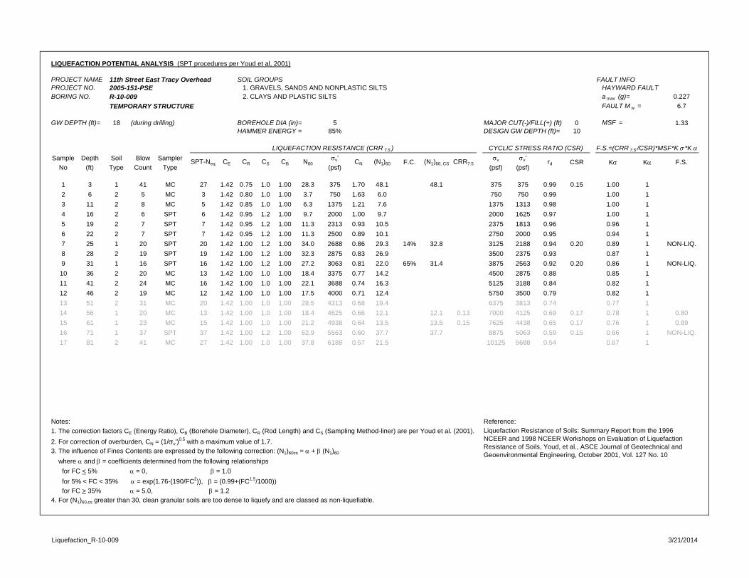
LIQUEFACTION POTENTIAL ANALYSIS (SPT procedures per Youd et al, 2001)
PROJECT NAME 11th Street East Tracy Overhead SOIL GROUPS FAULT INFOPROJECT NO. 2005-151-PSE 1. GRAVELS, SANDS AND NONPLASTIC SILTS HAYWARD FAULTBORING NO. R-10-009 2. CLAYS AND PLASTIC SILTS a max (g)= 0.227
TEMPORARY STRUCTURE FAULT M w = 6.7
GW DEPTH (ft)= 18 (during drilling) BOREHOLE DIA (in)= 5 MAJOR CUT(-)/FILL(+) (ft) 0 MSF = 1.33HAMMER ENERGY = 85% DESIGN GW DEPTH (ft)= 10
Sample Depth Soil Blow Sampler v' v v'No (ft) Type Count Type (psf) (psf) (psf)
1 3 1 41 MC 27 1.42 0.75 1.0 1.00 28.3 375 1.70 48.1 48.1 375 375 0.99 0.15 1.00 12 6 2 5 MC 3 1.42 0.80 1.0 1.00 3.7 750 1.63 6.0 750 750 0.99 1.00 13 11 2 8 MC 5 1.42 0.85 1.0 1.00 6.3 1375 1.21 7.6 1375 1313 0.98 1.00 14 16 2 6 SPT 6 1.42 0.95 1.2 1.00 9.7 2000 1.00 9.7 2000 1625 0.97 1.00 15 19 2 7 SPT 7 1.42 0.95 1.2 1.00 11.3 2313 0.93 10.5 2375 1813 0.96 0.96 16 22 2 7 SPT 7 1.42 0.95 1.2 1.00 11.3 2500 0.89 10.1 2750 2000 0.95 0.94 17 25 1 20 SPT 20 1.42 1.00 1.2 1.00 34.0 2688 0.86 29.3 14% 32.8 3125 2188 0.94 0.20 0.89 1 NON-LIQ.8 28 2 19 SPT 19 1.42 1.00 1.2 1.00 32.3 2875 0.83 26.9 3500 2375 0.93 0.87 19 31 1 16 SPT 16 1.42 1.00 1.2 1.00 27.2 3063 0.81 22.0 65% 31.4 3875 2563 0.92 0.20 0.86 1 NON-LIQ.10 36 2 20 MC 13 1.42 1.00 1.0 1.00 18.4 3375 0.77 14.2 4500 2875 0.88 0.85 111 41 2 24 MC 16 1.42 1.00 1.0 1.00 22.1 3688 0.74 16.3 5125 3188 0.84 0.82 112 46 2 19 MC 12 1.42 1.00 1.0 1.00 17.5 4000 0.71 12.4 5750 3500 0.79 0.82 113 51 2 31 MC 20 1.42 1.00 1.0 1.00 28.5 4313 0.68 19.4 6375 3813 0.74 0.77 114 56 1 20 MC 13 1.42 1.00 1.0 1.00 18.4 4625 0.66 12.1 12.1 0.13 7000 4125 0.69 0.17 0.78 1 0.8015 61 1 23 MC 15 1.42 1.00 1.0 1.00 21.2 4938 0.64 13.5 13.5 0.15 7625 4438 0.65 0.17 0.76 1 0.8916 71 1 37 SPT 37 1.42 1.00 1.2 1.00 62.9 5563 0.60 37.7 37.7 8875 5063 0.59 0.15 0.66 1 NON-LIQ.17 81 2 41 MC 27 1.42 1.00 1.0 1.00 37.8 6188 0.57 21.5 10125 5688 0.54 0.67 1
Notes: Reference: 1. The correction factors CE (Energy Ratio), CB (Borehole Diameter), CR (Rod Length) and CS (Sampling Method-liner) are per Youd et al. (2001).2. For correction of overburden, CN = (1/v')
0.5 with a maximum value of 1.7. 3. The influence of Fines Contents are expressed by the following correction: (N1)60cs = + (N1)60
where and = coefficients determined from the following relationships for FC < 5% = 0, = 1.0 for 5% < FC < 35% = exp(1.76-(190/FC2)), = (0.99+(FC1.5/1000)) for FC > 35% = 5.0, = 1.24. For (N1)60,cs greater than 30, clean granular soils are too dense to liquefy and are classed as non-liquefiable.
LIQUEFACTION RESISTANCE (CRR 7.5 ) CYCLIC STRESS RATIO (CSR) F.S.=(CRR 7.5 /CSR)*MSF*K *K
SPT-Neq. CE CR CS CB N60 CN (N1)60 F.C. (N1)60, CS CRR7.5 rd
Liquefaction Resistance of Soils: Summary Report from the 1996 NCEER and 1998 NCEER Workshops on Evaluation of Liquefaction Resistance of Soils, Youd, et al., ASCE Journal of Geotechnical and Geoenvironmental Engineering, October 2001, Vol. 127 No. 10
K K F.S.CSR
Liquefaction_R-10-009 3/21/2014
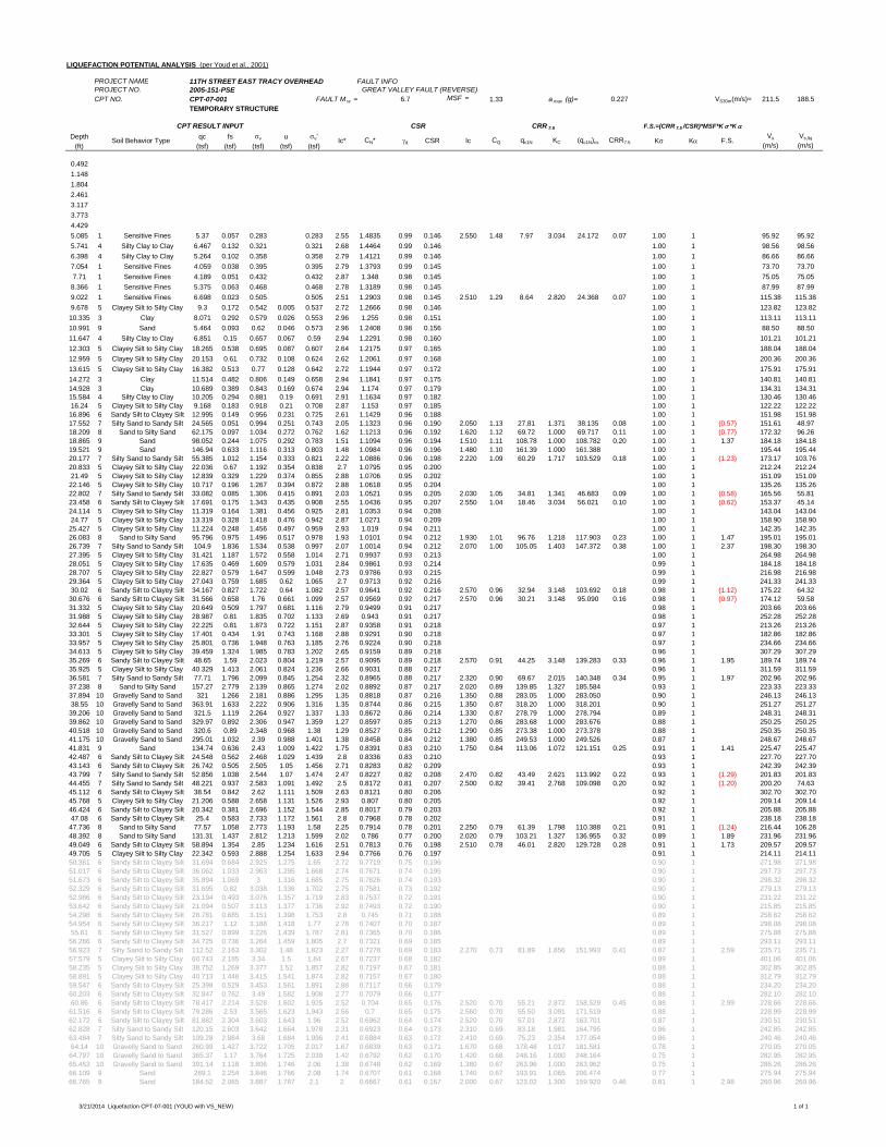
LIQUEFACTION POTENTIAL ANALYSIS (per Youd et al., 2001)
PROJECT NAME 11TH STREET EAST TRACY OVERHEAD FAULT INFOPROJECT NO. 2005-151-PSE GREAT VALLEY FAULT (REVERSE)CPT NO. CPT-07-001 FAULT M w = 6.7 MSF = 1.33 a max (g)= 0.227 VS30m(m/s)= 211.5 188.5
TEMPORARY STRUCTURE
Depth qc fs v u v'(ft) (tsf) (tsf) (tsf) (tsf) (tsf)
0.4921.1481.8042.4613.1173.7734.4295.085 1 Sensitive Fines 5.37 0.057 0.283 0.283 2.55 1.4835 0.99 0.146 2.550 1.48 7.97 3.034 24.172 0.07 1.00 1 95.92 95.925.741 4 Silty Clay to Clay 6.467 0.132 0.321 0.321 2.68 1.4464 0.99 0.146 1.00 1 98.56 98.566.398 4 Silty Clay to Clay 5.264 0.102 0.358 0.358 2.79 1.4121 0.99 0.146 1.00 1 86.66 86.667.054 1 Sensitive Fines 4.059 0.038 0.395 0.395 2.79 1.3793 0.99 0.145 1.00 1 73.70 73.707.71 1 Sensitive Fines 4.189 0.051 0.432 0.432 2.87 1.348 0.98 0.145 1.00 1 75.05 75.058.366 1 Sensitive Fines 5.375 0.063 0.468 0.468 2.78 1.3189 0.98 0.145 1.00 1 87.99 87.999.022 1 Sensitive Fines 6.698 0.023 0.505 0.505 2.51 1.2903 0.98 0.145 2.510 1.29 8.64 2.820 24.368 0.07 1.00 1 115.38 115.389.678 5 Clayey Silt to Silty Clay 9.3 0.172 0.542 0.005 0.537 2.72 1.2666 0.98 0.146 1.00 1 123.82 123.8210.335 3 Clay 8.071 0.292 0.579 0.026 0.553 2.96 1.255 0.98 0.151 1.00 1 113.11 113.1110.991 9 Sand 5.464 0.093 0.62 0.046 0.573 2.96 1.2408 0.98 0.156 1.00 1 88.50 88.5011.647 4 Silty Clay to Clay 6.851 0.15 0.657 0.067 0.59 2.94 1.2291 0.98 0.160 1.00 1 101.21 101.2112.303 5 Clayey Silt to Silty Clay 18.265 0.538 0.695 0.087 0.607 2.64 1.2175 0.97 0.165 1.00 1 188.04 188.0412.959 5 Clayey Silt to Silty Clay 20.153 0.61 0.732 0.108 0.624 2.62 1.2061 0.97 0.168 1.00 1 200.36 200.3613.615 5 Clayey Silt to Silty Clay 16.382 0.513 0.77 0.128 0.642 2.72 1.1944 0.97 0.172 1.00 1 175.91 175.9114.272 3 Clay 11.514 0.482 0.806 0.149 0.658 2.94 1.1841 0.97 0.175 1.00 1 140.81 140.8114.928 3 Clay 10.689 0.389 0.843 0.169 0.674 2.94 1.174 0.97 0.179 1.00 1 134.31 134.3115.584 4 Silty Clay to Clay 10.205 0.294 0.881 0.19 0.691 2.91 1.1634 0.97 0.182 1.00 1 130.46 130.4616.24 5 Clayey Silt to Silty Clay 9.168 0.183 0.918 0.21 0.708 2.87 1.153 0.97 0.185 1.00 1 122.22 122.2216.896 6 Sandy Silt to Clayey Silt 12.995 0.149 0.956 0.231 0.725 2.61 1.1429 0.96 0.188 1.00 1 151.98 151.9817.552 7 Silty Sand to Sandy Silt 24.565 0.051 0.994 0.251 0.743 2.05 1.1323 0.96 0.190 2.050 1.13 27.81 1.371 38.135 0.08 1.00 1 (0.57) 151.61 48.9718.209 8 Sand to Silty Sand 62.175 0.097 1.034 0.272 0.762 1.62 1.1213 0.96 0.192 1.620 1.12 69.72 1.000 69.717 0.11 1.00 1 (0.77) 172.32 96.2618.865 9 Sand 98.052 0.244 1.075 0.292 0.783 1.51 1.1094 0.96 0.194 1.510 1.11 108.78 1.000 108.782 0.20 1.00 1 1.37 184.18 184.1819.521 9 Sand 146.94 0.633 1.116 0.313 0.803 1.48 1.0984 0.96 0.196 1.480 1.10 161.39 1.000 161.388 1.00 1 195.44 195.4420.177 7 Silty Sand to Sandy Silt 55.385 1.012 1.154 0.333 0.821 2.22 1.0886 0.96 0.198 2.220 1.09 60.29 1.717 103.529 0.18 1.00 1 (1.23) 173.17 103.7620.833 5 Clayey Silt to Silty Clay 22.036 0.67 1.192 0.354 0.838 2.7 1.0795 0.95 0.200 1.00 1 212.24 212.2421.49 5 Clayey Silt to Silty Clay 12.839 0.329 1.229 0.374 0.855 2.88 1.0706 0.95 0.202 1.00 1 151.09 151.0922.146 5 Clayey Silt to Silty Clay 10.717 0.196 1.267 0.394 0.872 2.88 1.0618 0.95 0.204 1.00 1 135.26 135.2622.802 7 Silty Sand to Sandy Silt 33.082 0.085 1.306 0.415 0.891 2.03 1.0521 0.95 0.205 2.030 1.05 34.81 1.341 46.683 0.09 1.00 1 (0.58) 165.56 55.8123.458 6 Sandy Silt to Clayey Silt 17.691 0.175 1.343 0.435 0.908 2.55 1.0436 0.95 0.207 2.550 1.04 18.46 3.034 56.021 0.10 1.00 1 (0.62) 153.37 45.1424.114 5 Clayey Silt to Silty Clay 11.319 0.164 1.381 0.456 0.925 2.81 1.0353 0.94 0.208 1.00 1 143.04 143.0424.77 5 Clayey Silt to Silty Clay 13.319 0.328 1.418 0.476 0.942 2.87 1.0271 0.94 0.209 1.00 1 158.90 158.9025.427 5 Clayey Silt to Silty Clay 11.224 0.248 1.456 0.497 0.959 2.93 1.019 0.94 0.211 1.00 1 142.35 142.3526.083 8 Sand to Silty Sand 95.796 0.975 1.496 0.517 0.978 1.93 1.0101 0.94 0.212 1.930 1.01 96.76 1.218 117.903 0.23 1.00 1 1.47 195.01 195.0126.739 7 Silty Sand to Sandy Silt 104.9 1.836 1.534 0.538 0.997 2.07 1.0014 0.94 0.212 2.070 1.00 105.05 1.403 147.372 0.38 1.00 1 2.37 198.30 198.3027.395 5 Clayey Silt to Silty Clay 31.421 1.187 1.572 0.558 1.014 2.71 0.9937 0.93 0.213 1.00 1 264.98 264.9828.051 5 Clayey Silt to Silty Clay 17.635 0.469 1.609 0.579 1.031 2.84 0.9861 0.93 0.214 0.99 1 184.18 184.1828.707 5 Clayey Silt to Silty Clay 22.827 0.579 1.647 0.599 1.048 2.73 0.9786 0.93 0.215 0.99 1 216.98 216.9829.364 5 Clayey Silt to Silty Clay 27.043 0.759 1.685 0.62 1.065 2.7 0.9713 0.92 0.216 0.99 1 241.33 241.3330.02 6 Sandy Silt to Clayey Silt 34.167 0.827 1.722 0.64 1.082 2.57 0.9641 0.92 0.216 2.570 0.96 32.94 3.148 103.692 0.18 0.98 1 (1.12) 175.22 64.3230.676 6 Sandy Silt to Clayey Silt 31.566 0.658 1.76 0.661 1.099 2.57 0.9569 0.92 0.217 2.570 0.96 30.21 3.148 95.090 0.16 0.98 1 (0.97) 174.12 59.5831.332 5 Clayey Silt to Silty Clay 20.649 0.509 1.797 0.681 1.116 2.79 0.9499 0.91 0.217 0.98 1 203.66 203.6631.988 5 Clayey Silt to Silty Clay 28.987 0.81 1.835 0.702 1.133 2.69 0.943 0.91 0.217 0.98 1 252.28 252.2832.644 5 Clayey Silt to Silty Clay 22.225 0.81 1.873 0.722 1.151 2.87 0.9358 0.91 0.218 0.97 1 213.26 213.2633.301 5 Clayey Silt to Silty Clay 17.401 0.434 1.91 0.743 1.168 2.88 0.9291 0.90 0.218 0.97 1 182.86 182.8633.957 5 Clayey Silt to Silty Clay 25.801 0.736 1.948 0.763 1.185 2.76 0.9224 0.90 0.218 0.97 1 234.66 234.6634.613 5 Clayey Silt to Silty Clay 39.459 1.324 1.985 0.783 1.202 2.65 0.9159 0.89 0.218 0.96 1 307.29 307.2935.269 6 Sandy Silt to Clayey Silt 48.65 1.59 2.023 0.804 1.219 2.57 0.9095 0.89 0.218 2.570 0.91 44.25 3.148 139.283 0.33 0.96 1 1.95 189.74 189.7435.925 5 Clayey Silt to Silty Clay 40.329 1.413 2.061 0.824 1.236 2.66 0.9031 0.88 0.217 0.96 1 311.59 311.5936.581 7 Silty Sand to Sandy Silt 77.71 1.796 2.099 0.845 1.254 2.32 0.8965 0.88 0.217 2.320 0.90 69.67 2.015 140.348 0.34 0.95 1 1.97 202.96 202.9637.238 8 Sand to Silty Sand 157.27 2.779 2.139 0.865 1.274 2.02 0.8892 0.87 0.217 2.020 0.89 139.85 1.327 185.584 0.93 1 223.33 223.3337.894 10 Gravelly Sand to Sand 321 1.266 2.181 0.886 1.295 1.35 0.8818 0.87 0.216 1.350 0.88 283.05 1.000 283.050 0.90 1 246.13 246.1338.55 10 Gravelly Sand to Sand 363.91 1.633 2.222 0.906 1.316 1.35 0.8744 0.86 0.215 1.350 0.87 318.20 1.000 318.201 0.90 1 251.27 251.2739.206 10 Gravelly Sand to Sand 321.5 1.119 2.264 0.927 1.337 1.33 0.8672 0.86 0.214 1.330 0.87 278.79 1.000 278.794 0.89 1 248.31 248.3139.862 10 Gravelly Sand to Sand 329.97 0.892 2.306 0.947 1.359 1.27 0.8597 0.85 0.213 1.270 0.86 283.68 1.000 283.676 0.88 1 250.25 250.2540.518 10 Gravelly Sand to Sand 320.6 0.89 2.348 0.968 1.38 1.29 0.8527 0.85 0.212 1.290 0.85 273.38 1.000 273.378 0.88 1 250.35 250.3541.175 10 Gravelly Sand to Sand 295.01 1.032 2.39 0.988 1.401 1.38 0.8458 0.84 0.212 1.380 0.85 249.53 1.000 249.526 0.87 1 248.67 248.6741.831 9 Sand 134.74 0.636 2.43 1.009 1.422 1.75 0.8391 0.83 0.210 1.750 0.84 113.06 1.072 121.151 0.25 0.91 1 1.41 225.47 225.4742.487 6 Sandy Silt to Clayey Silt 24.548 0.562 2.468 1.029 1.439 2.8 0.8336 0.83 0.210 0.93 1 227.70 227.7043.143 6 Sandy Silt to Clayey Silt 26.742 0.505 2.505 1.05 1.456 2.71 0.8283 0.82 0.209 0.93 1 242.39 242.3943.799 7 Silty Sand to Sandy Silt 52.856 1.038 2.544 1.07 1.474 2.47 0.8227 0.82 0.208 2.470 0.82 43.49 2.621 113.992 0.22 0.93 1 (1.29) 201.83 201.8344.455 7 Silty Sand to Sandy Silt 48.221 0.937 2.583 1.091 1.492 2.5 0.8172 0.81 0.207 2.500 0.82 39.41 2.768 109.098 0.20 0.92 1 (1.20) 200.20 74.6345.112 6 Sandy Silt to Clayey Silt 38.54 0.842 2.62 1.111 1.509 2.63 0.8121 0.80 0.206 0.92 1 302.70 302.7045.768 5 Clayey Silt to Silty Clay 21.206 0.588 2.658 1.131 1.526 2.93 0.807 0.80 0.205 0.92 1 209.14 209.1446.424 6 Sandy Silt to Clayey Silt 20.342 0.381 2.696 1.152 1.544 2.85 0.8017 0.79 0.203 0.92 1 205.88 205.8847.08 6 Sandy Silt to Clayey Silt 25.4 0.583 2.733 1.172 1.561 2.8 0.7968 0.78 0.202 0.91 1 238.18 238.1847.736 8 Sand to Silty Sand 77.57 1.058 2.773 1.193 1.58 2.25 0.7914 0.78 0.201 2.250 0.79 61.39 1.798 110.388 0.21 0.91 1 (1.24) 216.44 106.2848.392 8 Sand to Silty Sand 131.31 1.437 2.812 1.213 1.599 2.02 0.786 0.77 0.200 2.020 0.79 103.21 1.327 136.955 0.32 0.89 1 1.89 231.96 231.9649.049 6 Sandy Silt to Clayey Silt 58.894 1.354 2.85 1.234 1.616 2.51 0.7813 0.76 0.198 2.510 0.78 46.01 2.820 129.728 0.28 0.91 1 1.73 209.57 209.5749.705 5 Clayey Silt to Silty Clay 22.342 0.593 2.888 1.254 1.633 2.94 0.7766 0.76 0.197 0.91 1 214.11 214.1150.361 6 Sandy Silt to Clayey Silt 31.694 0.684 2.925 1.275 1.65 2.72 0.7719 0.75 0.196 0.90 1 271.98 271.9851.017 6 Sandy Silt to Clayey Silt 36.062 1.033 2.963 1.295 1.668 2.74 0.7671 0.74 0.195 0.90 1 297.73 297.7351.673 6 Sandy Silt to Clayey Silt 35.894 1.069 3 1.316 1.685 2.75 0.7626 0.74 0.193 0.90 1 298.32 298.3252.329 6 Sandy Silt to Clayey Silt 31.695 0.82 3.038 1.336 1.702 2.75 0.7581 0.73 0.192 0.90 1 279.13 279.1352.986 6 Sandy Silt to Clayey Silt 23.194 0.493 3.076 1.357 1.719 2.83 0.7537 0.72 0.191 0.90 1 231.22 231.2253.642 6 Sandy Silt to Clayey Silt 21.094 0.507 3.113 1.377 1.736 2.92 0.7493 0.72 0.190 0.90 1 215.85 215.8554.298 6 Sandy Silt to Clayey Silt 28.781 0.685 3.151 1.398 1.753 2.8 0.745 0.71 0.188 0.89 1 258.62 258.6254.954 6 Sandy Silt to Clayey Silt 36.217 1.12 3.188 1.418 1.77 2.78 0.7407 0.70 0.187 0.89 1 298.08 298.0855.61 6 Sandy Silt to Clayey Silt 31.527 0.899 3.226 1.439 1.787 2.81 0.7365 0.70 0.186 0.89 1 275.88 275.8856.266 6 Sandy Silt to Clayey Silt 34.725 0.736 3.264 1.459 1.805 2.7 0.7321 0.69 0.185 0.89 1 293.11 293.1156.923 7 Silty Sand to Sandy Silt 112.52 2.163 3.302 1.48 1.823 2.27 0.7278 0.69 0.183 2.270 0.73 81.89 1.856 151.993 0.41 0.87 1 2.59 235.71 235.7157.579 5 Clayey Silt to Silty Clay 60.743 2.185 3.34 1.5 1.84 2.67 0.7237 0.68 0.182 0.89 1 401.06 401.0658.235 5 Clayey Silt to Silty Clay 38.752 1.269 3.377 1.52 1.857 2.82 0.7197 0.67 0.181 0.88 1 302.85 302.8558.891 5 Clayey Silt to Silty Clay 40.713 1.446 3.415 1.541 1.874 2.82 0.7157 0.67 0.180 0.88 1 312.79 312.7959.547 6 Sandy Silt to Clayey Silt 25.398 0.529 3.453 1.561 1.891 2.88 0.7117 0.66 0.179 0.88 1 234.20 234.2060.203 6 Sandy Silt to Clayey Silt 32.847 0.762 3.49 1.582 1.908 2.77 0.7079 0.66 0.177 0.88 1 282.10 282.1060.86 6 Sandy Silt to Clayey Silt 78.417 2.214 3.528 1.602 1.925 2.52 0.704 0.65 0.176 2.520 0.70 55.21 2.872 158.529 0.45 0.88 1 2.99 228.66 228.6661.516 6 Sandy Silt to Clayey Silt 79.286 2.53 3.565 1.623 1.943 2.56 0.7 0.65 0.175 2.560 0.70 55.50 3.091 171.519 0.88 1 228.99 228.9962.172 6 Sandy Silt to Clayey Silt 81.882 2.304 3.603 1.643 1.96 2.52 0.6962 0.64 0.174 2.520 0.70 57.01 2.872 163.701 0.87 1 230.51 230.5162.828 7 Silty Sand to Sandy Silt 120.15 2.603 3.642 1.664 1.978 2.31 0.6923 0.64 0.173 2.310 0.69 83.18 1.981 164.795 0.86 1 242.85 242.8563.484 7 Silty Sand to Sandy Silt 109.28 2.884 3.68 1.684 1.996 2.41 0.6884 0.63 0.172 2.410 0.69 75.23 2.354 177.054 0.86 1 240.46 240.4664.14 10 Gravelly Sand to Sand 260.99 1.427 3.722 1.705 2.017 1.67 0.6839 0.63 0.171 1.670 0.68 178.48 1.017 181.581 0.78 1 270.05 270.0564.797 10 Gravelly Sand to Sand 365.37 1.17 3.764 1.725 2.039 1.42 0.6792 0.62 0.170 1.420 0.68 248.16 1.000 248.164 0.75 1 282.95 282.9565.453 10 Gravelly Sand to Sand 391.14 1.118 3.806 1.746 2.06 1.38 0.6748 0.62 0.169 1.380 0.67 263.96 1.000 263.962 0.75 1 286.26 286.2666.109 9 Sand 289.1 2.254 3.846 1.766 2.08 1.74 0.6707 0.61 0.168 1.740 0.67 193.91 1.065 206.474 0.77 1 275.94 275.9466.765 9 Sand 184.52 2.065 3.887 1.787 2.1 2 0.6667 0.61 0.167 2.000 0.67 123.02 1.300 159.920 0.46 0.81 1 2.98 260.96 260.96
CPT RESULT INPUT CSR CRR 7.5 F.S.=(CRR 7.5 /CSR)*MSF*K *K
Soil Behavior Type Ic* CN* d CSR Ic CQ qc1N KC (qc1N)cs CRR7.5 K K F.S.Vs
(m/s)Vs,liq
(m/s)
3/21/2014 Liquefaction CPT-07-001 (YOUD with VS_NEW) 1 of 1
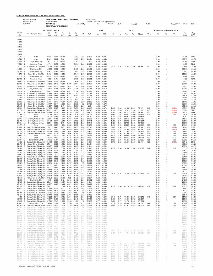
LIQUEFACTION POTENTIAL ANALYSIS (per Youd et al., 2001)
PROJECT NAME 11TH STREET EAST TRACY OVERHEAD FAULT INFOPROJECT NO. 2005-151-PSE GREAT VALLEY FAULT (REVERSE)CPT NO. CPT-07-002 FAULT M w = 6.7 MSF = 1.33 a max (g)= 0.227 VS30m(m/s)= 219.6 197.4
TEMPORARY STRUCTURE
Depth qc fs v u v'(ft) (tsf) (tsf) (tsf) (tsf) (tsf)
0.4921.1481.8042.4613.1173.7734.4295.085 3 Clay 4.818 0.144 0.283 0.283 2.85 1.4835 0.99 0.146 1.00 1 81.84 81.845.741 3 Clay 7.581 0.262 0.32 0.32 2.76 1.4474 0.99 0.146 1.00 1 108.75 108.756.398 4 Silty Clay to Clay 6.2 0.13 0.357 0.357 2.75 1.413 0.99 0.146 1.00 1 95.86 95.867.054 1 Sensitive Fines 4.779 0.077 0.394 0.394 2.83 1.3802 0.99 0.145 1.00 1 81.62 81.627.71 5 Clayey Silt to Silty Clay 18.053 0.384 0.432 0.432 2.42 1.348 0.98 0.145 2.420 1.35 24.34 2.396 58.306 0.10 1.00 1 125.90 125.908.366 4 Silty Clay to Clay 12.733 0.392 0.469 0.469 2.68 1.3182 0.98 0.145 1.00 1 150.13 150.139.022 4 Silty Clay to Clay 6.907 0.143 0.507 0.507 2.84 1.2888 0.98 0.145 1.00 1 102.43 102.439.678 5 Clayey Silt to Silty Clay 8.032 0.108 0.544 0.544 2.71 1.2615 0.98 0.145 1.00 1 113.20 113.2010.335 4 Silty Clay to Clay 6.618 0.132 0.582 0.582 2.91 1.2346 0.98 0.144 1.00 1 99.51 99.5110.991 1 Sensitive Fines 2.09 0.02 0.618 0.618 3.38 1.2101 0.98 0.144 1.00 1 48.53 48.5311.647 5 Clayey Silt to Silty Clay 13.423 0.308 0.656 0.656 2.71 1.1853 0.98 0.144 1.00 1 155.21 155.2112.303 5 Clayey Silt to Silty Clay 18.176 0.548 0.694 0.009 0.684 2.68 1.1677 0.97 0.146 1.00 1 188.89 188.8912.959 5 Clayey Silt to Silty Clay 18.632 0.516 0.731 0.03 0.701 2.66 1.1573 0.97 0.150 1.00 1 192.31 192.3113.615 4 Silty Clay to Clay 14.176 0.481 0.769 0.05 0.719 2.83 1.1464 0.97 0.153 1.00 1 160.62 160.6214.272 4 Silty Clay to Clay 9.859 0.297 0.806 0.071 0.736 2.95 1.1364 0.97 0.157 1.00 1 127.62 127.6214.928 5 Clayey Silt to Silty Clay 21.534 0.633 0.844 0.091 0.753 2.65 1.1265 0.97 0.160 1.00 1 209.01 209.0115.584 5 Clayey Silt to Silty Clay 22.258 0.687 0.882 0.112 0.77 2.67 1.1168 0.97 0.163 1.00 1 213.20 213.2016.24 5 Clayey Silt to Silty Clay 12.694 0.341 0.919 0.132 0.787 2.85 1.1072 0.97 0.166 1.00 1 149.68 149.6816.896 5 Clayey Silt to Silty Clay 9.865 0.205 0.957 0.153 0.804 2.9 1.0978 0.96 0.169 1.00 1 127.62 127.6217.552 5 Clayey Silt to Silty Clay 8.689 0.148 0.994 0.173 0.821 2.92 1.0886 0.96 0.172 1.00 1 117.81 117.8118.209 5 Clayey Silt to Silty Clay 10.477 0.144 1.032 0.194 0.838 2.8 1.0795 0.96 0.175 1.00 1 132.96 132.9618.865 5 Clayey Silt to Silty Clay 11.207 0.239 1.07 0.214 0.856 2.88 1.07 0.96 0.177 1.00 1 139.18 139.1819.521 6 Sandy Silt to Clayey Silt 27.188 0.385 1.107 0.235 0.873 2.43 1.0613 0.96 0.179 2.430 1.06 28.85 2.439 70.375 0.11 1.00 1 (0.84) 160.51 55.2220.177 6 Sandy Silt to Clayey Silt 26.62 0.655 1.145 0.255 0.89 2.59 1.0526 0.96 0.182 2.590 1.05 28.02 3.266 91.518 0.15 1.00 1 (1.11) 160.82 57.0320.833 7 Silty Sand to Sandy Silt 46.249 0.772 1.183 0.276 0.908 2.3 1.0436 0.95 0.184 2.300 1.04 48.27 1.949 94.060 0.16 1.00 1 (1.14) 173.79 84.0421.49 9 Sand 121.78 0.422 1.224 0.296 0.928 1.56 1.0338 0.95 0.185 1.560 1.03 125.90 1.000 125.896 0.27 1.00 1 1.91 198.30 198.3022.146 9 Sand 185.09 0.483 1.265 0.316 0.948 1.34 1.0242 0.95 0.187 1.340 1.02 189.57 1.000 189.573 1.00 1 210.62 210.6222.802 10 Gravelly Sand to Sand 233.5 0.465 1.307 0.337 0.97 1.21 1.0138 0.95 0.189 1.210 1.01 236.73 1.000 236.730 1.00 1 218.42 218.4223.458 10 Gravelly Sand to Sand 245.03 0.374 1.348 0.357 0.991 1.15 1.0041 0.95 0.190 1.150 1.00 246.03 1.000 246.034 1.00 1 221.07 221.0724.114 10 Gravelly Sand to Sand 228.6 0.138 1.39 0.378 1.012 1.12 0.9946 0.94 0.191 1.120 0.99 227.35 1.000 227.355 1.00 1 220.33 220.3324.77 9 Sand 136.06 0.205 1.431 0.398 1.033 1.41 0.9852 0.94 0.193 1.410 0.99 134.05 1.000 134.046 0.30 0.99 1 2.08 207.09 207.0925.427 7 Silty Sand to Sandy Silt 32 0.446 1.47 0.419 1.051 2.44 0.9773 0.94 0.194 2.440 0.98 31.27 2.483 77.660 0.12 0.99 1 (0.84) 172.49 58.2926.083 7 Silty Sand to Sandy Silt 33.46 0.295 1.508 0.439 1.069 2.32 0.9696 0.94 0.195 2.320 0.97 32.44 2.015 65.358 0.11 0.99 1 (0.71) 174.22 57.6626.739 6 Sandy Silt to Clayey Silt 39.053 0.943 1.546 0.46 1.086 2.52 0.9624 0.94 0.196 2.520 0.96 37.58 2.872 107.926 0.20 0.98 1 1.32 178.41 178.4127.395 7 Silty Sand to Sandy Silt 70.791 1.223 1.584 0.48 1.104 2.23 0.9549 0.93 0.197 2.230 0.95 67.60 1.743 117.850 0.23 0.98 1 1.54 193.65 193.6528.051 9 Sand 142.1 0.476 1.625 0.501 1.124 1.57 0.9466 0.93 0.198 1.570 0.95 134.51 1.000 134.513 0.31 0.96 1 1.99 213.06 213.0628.707 9 Sand 136.76 0.606 1.666 0.521 1.145 1.65 0.9382 0.93 0.199 1.650 0.94 128.30 1.003 128.731 0.28 0.96 1 1.79 213.06 213.0629.364 8 Sand to Silty Sand 100.21 0.83 1.706 0.542 1.164 1.92 0.9306 0.92 0.200 1.920 0.93 93.26 1.208 112.685 0.21 0.96 1 1.37 205.52 205.5230.02 6 Sandy Silt to Clayey Silt 31.483 0.599 1.743 0.562 1.181 2.57 0.924 0.92 0.200 2.570 0.92 29.09 3.148 91.573 0.15 0.97 1 (0.97) 177.42 57.6630.676 5 Clayey Silt to Silty Clay 17.54 0.386 1.781 0.583 1.198 2.85 0.9174 0.92 0.201 0.96 1 183.33 183.3331.332 6 Sandy Silt to Clayey Silt 34.457 0.892 1.818 0.603 1.215 2.63 0.911 0.91 0.202 0.96 1 280.72 280.7231.988 6 Sandy Silt to Clayey Silt 39.883 0.976 1.856 0.624 1.232 2.57 0.9046 0.91 0.202 2.570 0.90 36.08 3.148 113.573 0.22 0.96 1 1.37 185.13 185.1332.644 6 Sandy Silt to Clayey Silt 25.784 0.577 1.894 0.644 1.25 2.71 0.898 0.91 0.203 0.96 1 234.31 234.3133.301 6 Sandy Silt to Clayey Silt 24.447 0.566 1.931 0.664 1.267 2.74 0.8918 0.90 0.203 0.95 1 227.64 227.6433.957 6 Sandy Silt to Clayey Silt 26.157 0.7 1.969 0.685 1.284 2.76 0.8857 0.90 0.203 0.95 1 238.34 238.3434.613 5 Clayey Silt to Silty Clay 20.365 0.508 2.006 0.705 1.301 2.84 0.8796 0.89 0.203 0.95 1 204.96 204.9635.269 6 Sandy Silt to Clayey Silt 22.676 0.501 2.044 0.726 1.318 2.76 0.8737 0.89 0.203 0.95 1 220.96 220.9635.925 6 Sandy Silt to Clayey Silt 34.964 0.849 2.082 0.746 1.335 2.62 0.8679 0.88 0.203 0.94 1 290.20 290.2036.581 6 Sandy Silt to Clayey Silt 38.105 0.94 2.119 0.767 1.352 2.6 0.8621 0.88 0.203 0.94 1 189.37 189.3737.238 6 Sandy Silt to Clayey Silt 26.77 0.689 2.157 0.787 1.369 2.78 0.8564 0.87 0.203 0.94 1 239.42 239.4237.894 6 Sandy Silt to Clayey Silt 22.37 0.488 2.194 0.808 1.386 2.81 0.8507 0.87 0.203 0.94 1 214.11 214.1138.55 6 Sandy Silt to Clayey Silt 29.823 0.771 2.232 0.828 1.404 2.74 0.8449 0.86 0.203 0.93 1 256.90 256.9039.206 6 Sandy Silt to Clayey Silt 34.234 0.975 2.269 0.849 1.421 2.72 0.8394 0.86 0.202 0.93 1 280.77 280.7739.862 6 Sandy Silt to Clayey Silt 48.828 1.035 2.307 0.869 1.438 2.51 0.834 0.85 0.202 2.510 0.83 40.72 2.820 114.813 0.22 0.93 1 1.36 198.26 198.2640.518 6 Sandy Silt to Clayey Silt 28.174 0.591 2.345 0.89 1.455 2.73 0.8286 0.85 0.201 0.93 1 247.83 247.8341.175 5 Clayey Silt to Silty Clay 37.069 1.278 2.382 0.91 1.472 2.75 0.8234 0.84 0.201 0.93 1 294.70 294.7041.831 4 Silty Clay to Clay 27.2 1.067 2.42 0.931 1.489 2.91 0.8181 0.83 0.200 0.92 1 242.95 242.9542.487 6 Sandy Silt to Clayey Silt 23.89 0.593 2.457 0.951 1.506 2.84 0.813 0.83 0.199 0.92 1 224.90 224.9043.143 6 Sandy Silt to Clayey Silt 38.267 1.023 2.495 0.972 1.523 2.68 0.8079 0.82 0.199 0.92 1 302.31 302.3143.799 6 Sandy Silt to Clayey Silt 62.03 1.77 2.533 0.992 1.541 2.53 0.8026 0.82 0.198 2.530 0.80 49.79 2.925 145.615 0.37 0.92 1 2.27 208.37 208.3744.455 6 Sandy Silt to Clayey Silt 41.873 1.154 2.57 1.013 1.558 2.67 0.7977 0.81 0.197 0.92 1 317.67 317.6745.112 5 Clayey Silt to Silty Clay 23.177 0.675 2.608 1.033 1.575 2.93 0.7928 0.80 0.196 0.91 1 219.31 219.3145.768 5 Clayey Silt to Silty Clay 18.961 0.428 2.645 1.053 1.592 2.95 0.788 0.80 0.195 0.91 1 193.91 193.9146.424 6 Sandy Silt to Clayey Silt 29.449 0.836 2.683 1.074 1.609 2.82 0.7832 0.79 0.194 0.91 1 256.46 256.4647.08 6 Sandy Silt to Clayey Silt 68.508 2.144 2.721 1.094 1.626 2.54 0.7785 0.78 0.193 2.540 0.78 53.33 2.979 158.876 0.45 0.91 1 2.84 214.26 214.2647.736 6 Sandy Silt to Clayey Silt 79.977 2.435 2.758 1.115 1.643 2.49 0.7738 0.78 0.192 2.490 0.77 61.89 2.718 168.237 0.91 1 219.13 219.1348.392 6 Sandy Silt to Clayey Silt 97.211 2.746 2.796 1.135 1.66 2.4 0.7692 0.77 0.191 2.400 0.77 74.78 2.312 172.914 0.90 1 225.38 225.3849.049 8 Sand to Silty Sand 140.13 2.161 2.835 1.156 1.68 2.11 0.7639 0.76 0.190 2.110 0.76 107.04 1.473 157.692 0.44 0.87 1 2.72 237.08 237.0849.705 7 Silty Sand to Sandy Silt 80.901 2.073 2.874 1.176 1.698 2.44 0.7591 0.76 0.189 2.440 0.76 61.42 2.483 152.503 0.41 0.90 1 2.61 221.39 221.3950.361 6 Sandy Silt to Clayey Silt 33.477 0.959 2.912 1.197 1.715 2.8 0.7547 0.75 0.188 0.90 1 276.55 276.5551.017 6 Sandy Silt to Clayey Silt 26.352 0.546 2.949 1.217 1.732 2.82 0.7503 0.74 0.187 0.90 1 239.30 239.3051.673 6 Sandy Silt to Clayey Silt 28.553 0.599 2.987 1.238 1.749 2.78 0.746 0.74 0.185 0.89 1 255.06 255.0652.329 6 Sandy Silt to Clayey Silt 29.249 0.743 3.024 1.258 1.766 2.8 0.7417 0.73 0.184 0.89 1 263.01 263.0152.986 6 Sandy Silt to Clayey Silt 27.272 0.771 3.062 1.279 1.783 2.86 0.7375 0.72 0.183 0.89 1 252.23 252.2353.642 5 Clayey Silt to Silty Clay 24.837 0.763 3.1 1.299 1.801 2.94 0.7331 0.72 0.182 0.89 1 236.36 236.3654.298 5 Clayey Silt to Silty Clay 17.824 0.46 3.137 1.32 1.818 3.04 0.729 0.71 0.181 0.89 1 193.01 193.0154.954 6 Sandy Silt to Clayey Silt 23.231 0.583 3.175 1.34 1.835 2.91 0.7249 0.70 0.180 0.89 1 228.45 228.4555.61 6 Sandy Silt to Clayey Silt 40.868 1.24 3.212 1.361 1.852 2.75 0.7208 0.70 0.179 0.88 1 319.76 319.7656.266 5 Clayey Silt to Silty Clay 34.034 1.036 3.25 1.381 1.869 2.85 0.7168 0.69 0.177 0.88 1 280.41 280.4156.923 6 Sandy Silt to Clayey Silt 19.022 0.404 3.288 1.401 1.886 2.99 0.7129 0.69 0.176 0.88 1 200.42 200.4257.579 7 Silty Sand to Sandy Silt 48.75 0.728 3.326 1.422 1.904 2.51 0.7088 0.68 0.175 2.510 0.71 34.55 2.820 97.420 0.17 0.88 1 1.11 214.64 67.1758.235 7 Silty Sand to Sandy Silt 67.923 1.195 3.365 1.442 1.922 2.45 0.7047 0.67 0.174 2.450 0.70 47.86 2.528 121.010 0.24 0.88 1 1.65 223.76 223.7658.891 6 Sandy Silt to Clayey Silt 24.292 0.614 3.403 1.463 1.94 2.96 0.7006 0.67 0.173 0.88 1 227.41 227.4159.547 6 Sandy Silt to Clayey Silt 23.484 0.431 3.44 1.483 1.957 2.88 0.6969 0.66 0.172 0.87 1 226.13 226.1360.203 6 Sandy Silt to Clayey Silt 26.77 0.547 3.478 1.504 1.974 2.84 0.6931 0.66 0.171 0.87 1 248.00 248.0060.86 6 Sandy Silt to Clayey Silt 34.262 0.855 3.515 1.524 1.991 2.79 0.6894 0.65 0.170 0.87 1 289.05 289.0561.516 7 Silty Sand to Sandy Silt 73.961 1.627 3.554 1.545 2.009 2.48 0.6856 0.65 0.169 2.480 0.69 50.71 2.669 135.351 0.31 0.87 1 2.13 229.68 229.6862.172 8 Sand to Silty Sand 151.58 2.3 3.594 1.565 2.028 2.14 0.6815 0.64 0.168 2.140 0.68 103.31 1.532 158.265 0.45 0.84 1 2.98 251.99 251.9962.828 6 Sandy Silt to Clayey Silt 77.013 2.281 3.631 1.586 2.045 2.57 0.678 0.64 0.167 2.570 0.68 52.21 3.148 164.362 0.87 1 231.26 231.2663.484 10 Gravelly Sand to Sand 282.81 1.813 3.673 1.606 2.067 1.69 0.6734 0.63 0.166 1.690 0.67 190.44 1.031 196.363 0.77 1 274.69 274.6964.14 10 Gravelly Sand to Sand 437.49 1.48 3.715 1.627 2.088 1.38 0.6691 0.63 0.165 1.380 0.67 292.72 1.000 292.723 0.74 1 291.52 291.5264.797 10 Gravelly Sand to Sand 394.12 0.915 3.757 1.647 2.109 1.34 0.6649 0.62 0.164 1.340 0.66 262.03 1.000 262.031 0.74 1 288.37 288.3765.453 10 Gravelly Sand to Sand 388.42 1.085 3.798 1.668 2.131 1.39 0.6605 0.62 0.163 1.390 0.66 256.54 1.000 256.537 0.74 1 288.63 288.6366.109 10 Gravelly Sand to Sand 396.92 0.942 3.84 1.688 2.152 1.35 0.6563 0.61 0.162 1.350 0.66 260.51 1.000 260.505 0.74 1 290.21 290.2166.765 10 Gravelly Sand to Sand 255.47 1.328 3.882 1.709 2.173 1.69 0.6522 0.61 0.161 1.690 0.65 166.63 1.031 171.807 0.77 1 274.77 274.77
CPT RESULT INPUT CSR CRR 7.5 F.S.=(CRR 7.5 /CSR)*MSF*K *K
Soil Behavior Type Ic* CN* d CSR Ic CQ qc1N KC (qc1N)cs CRR7.5 K K F.S.Vs
(m/s)Vs,liq
(m/s)
3/21/2014 Liquefaction CPT-07-002 (YOUD with VS_NEW) 1 of 1
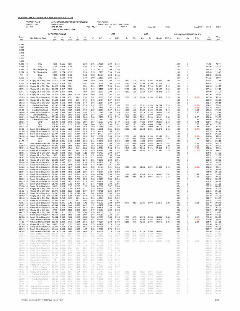
LIQUEFACTION POTENTIAL ANALYSIS (per Youd et al., 2001)
PROJECT NAME 11TH STREET EAST TRACY OVERHEAD FAULT INFOPROJECT NO. 2005-151-PSE GREAT VALLEY FAULT (REVERSE)CPT NO. CPT-07-003 FAULT M w = 6.7 MSF = 1.33 a max (g)= 0.227 VS30m(m/s)= 231.6 201.2
TEMPORARY STRUCTURE
Depth qc fs v u v'(ft) (tsf) (tsf) (tsf) (tsf) (tsf)
0.4921.1481.8042.4613.1173.7734.4295.085 3 Clay 4.339 0.111 0.283 0.283 2.85 1.4835 0.99 0.146 1.00 1 76.73 76.735.741 3 Clay 7.82 0.259 0.32 0.32 2.74 1.4474 0.99 0.146 1.00 1 110.99 110.996.398 4 Silty Clay to Clay 8.027 0.232 0.357 0.357 2.73 1.413 0.99 0.146 1.00 1 112.76 112.767.054 4 Silty Clay to Clay 8.779 0.274 0.395 0.395 2.76 1.3793 0.99 0.145 1.00 1 119.43 119.437.71 3 Clay 7.698 0.283 0.432 0.432 2.89 1.348 0.98 0.145 1.00 1 109.65 109.658.366 3 Clay 6.027 0.198 0.468 0.468 2.98 1.3189 0.98 0.145 1.00 1 94.00 94.009.022 5 Clayey Silt to Silty Clay 10.511 0.156 0.506 0.506 2.59 1.2896 0.98 0.145 2.590 1.29 13.55 3.266 44.270 0.09 1.00 1 122.58 122.589.678 5 Clayey Silt to Silty Clay 16.621 0.423 0.543 0.543 2.58 1.2622 0.98 0.145 2.580 1.26 20.98 3.206 67.268 0.11 1.00 1 132.61 132.6110.335 5 Clayey Silt to Silty Clay 24.325 0.654 0.581 0.581 2.49 1.2353 0.98 0.144 2.490 1.24 30.05 2.718 81.681 0.13 1.00 1 141.95 141.9510.991 5 Clayey Silt to Silty Clay 28.024 0.857 0.618 0.618 2.49 1.2101 0.98 0.144 2.490 1.21 33.91 2.718 92.187 0.15 1.00 1 147.16 147.1611.647 5 Clayey Silt to Silty Clay 24.637 0.856 0.656 0.656 2.59 1.1853 0.98 0.144 2.590 1.19 29.20 3.266 95.379 0.16 1.00 1 147.09 147.0912.303 5 Clayey Silt to Silty Clay 18.376 0.596 0.694 0.009 0.684 2.69 1.1677 0.97 0.146 1.00 1 190.96 190.9612.959 6 Sandy Silt to Clayey Silt 15.881 0.239 0.731 0.03 0.701 2.57 1.1573 0.97 0.150 2.570 1.16 18.38 3.148 57.856 0.10 1.00 1 (0.87) 140.95 45.3913.615 5 Clayey Silt to Silty Clay 14.544 0.418 0.769 0.05 0.719 2.78 1.1464 0.97 0.153 1.00 1 162.90 162.9014.272 5 Clayey Silt to Silty Clay 19.802 0.556 0.806 0.071 0.736 2.66 1.1364 0.97 0.157 1.00 1 198.16 198.1614.928 8 Sand to Silty Sand 45.247 0.264 0.846 0.091 0.755 1.97 1.1253 0.97 0.160 1.970 1.13 50.92 1.263 64.294 0.10 1.00 1 (0.87) 164.87 78.5015.584 8 Sand to Silty Sand 45.887 0.186 0.886 0.112 0.774 1.9 1.1145 0.97 0.163 1.900 1.11 51.14 1.189 60.798 0.10 1.00 1 (0.82) 166.28 76.9416.24 8 Sand to Silty Sand 76.479 0.661 0.925 0.132 0.793 1.89 1.1039 0.97 0.166 1.890 1.10 84.42 1.180 99.582 0.17 1.00 1 1.38 178.89 178.8916.896 6 Sandy Silt to Clayey Silt 72.864 1.848 0.963 0.153 0.81 2.23 1.0945 0.96 0.169 2.230 1.09 79.75 1.743 139.044 0.33 1.00 1 2.60 178.78 178.7817.552 4 Silty Clay to Clay 52.182 2.435 1.001 0.173 0.828 2.54 1.0848 0.96 0.172 2.540 1.08 56.61 2.979 168.633 1.00 1 172.18 172.1818.209 6 Sandy Silt to Clayey Silt 55.134 1.616 1.038 0.194 0.845 2.38 1.0758 0.96 0.174 2.380 1.08 59.31 2.233 132.421 0.30 1.00 1 2.27 174.38 174.3818.865 8 Sand to Silty Sand 86.254 0.595 1.078 0.214 0.864 1.82 1.0659 0.96 0.177 1.820 1.07 91.94 1.122 103.109 0.18 1.00 1 1.37 185.96 185.9619.521 9 Sand 101.28 0.293 1.119 0.235 0.884 1.57 1.0557 0.96 0.179 1.570 1.06 106.92 1.000 106.921 0.19 1.00 1 1.44 191.07 191.0720.177 9 Sand 106.01 0.182 1.159 0.255 0.904 1.48 1.0456 0.96 0.181 1.480 1.05 110.84 1.000 110.843 0.21 1.00 1 1.52 193.38 193.3820.833 9 Sand 105.98 0.329 1.2 0.276 0.925 1.59 1.0353 0.95 0.183 1.590 1.04 109.72 1.000 109.719 0.20 1.00 1 1.48 194.57 194.5721.49 6 Sandy Silt to Clayey Silt 26.754 0.531 1.238 0.296 0.942 2.55 1.0271 0.95 0.185 2.550 1.03 27.48 3.034 83.376 0.13 1.00 1 (0.97) 163.52 55.2222.146 6 Sandy Silt to Clayey Silt 14.728 0.243 1.275 0.316 0.959 2.74 1.019 0.95 0.187 1.00 1 167.74 167.7422.802 6 Sandy Silt to Clayey Silt 13.797 0.242 1.313 0.337 0.976 2.78 1.011 0.95 0.188 1.00 1 162.26 162.2623.458 6 Sandy Silt to Clayey Silt 21.262 0.309 1.351 0.357 0.993 2.57 1.0032 0.95 0.190 2.570 1.00 21.33 3.148 67.146 0.11 1.00 1 (0.76) 161.58 47.3324.114 9 Sand 105.31 0.461 1.391 0.378 1.013 1.7 0.9941 0.94 0.191 1.700 0.99 104.69 1.038 108.655 0.20 1.00 1 1.38 199.25 199.2524.77 9 Sand 169.54 1.031 1.432 0.398 1.034 1.61 0.9848 0.94 0.193 1.610 0.98 166.96 1.000 166.960 0.99 1 213.16 213.1625.427 7 Silty Sand to Sandy Silt 112.54 2.034 1.471 0.419 1.052 2.07 0.9769 0.94 0.194 2.070 0.98 109.94 1.403 154.239 0.42 0.99 1 2.86 203.03 203.0326.083 6 Sandy Silt to Clayey Silt 44.996 1.382 1.508 0.439 1.069 2.54 0.9696 0.94 0.195 2.540 0.97 43.63 2.979 129.966 0.28 0.99 1 1.92 180.97 180.9726.739 6 Sandy Silt to Clayey Silt 33.421 0.707 1.546 0.46 1.086 2.54 0.9624 0.94 0.196 2.540 0.96 32.16 2.979 95.815 0.16 0.98 1 (1.08) 174.83 62.2527.395 6 Sandy Silt to Clayey Silt 35.209 0.636 1.583 0.48 1.103 2.49 0.9553 0.93 0.197 2.490 0.96 33.63 2.718 91.431 0.15 0.98 1 (1.00) 176.76 63.6328.051 5 Clayey Silt to Silty Clay 16.182 0.393 1.621 0.501 1.12 2.88 0.9483 0.93 0.199 0.98 1 174.35 174.3528.707 5 Clayey Silt to Silty Clay 20.07 0.498 1.659 0.521 1.137 2.8 0.9414 0.93 0.200 0.97 1 199.92 199.9229.364 6 Sandy Silt to Clayey Silt 21.975 0.429 1.696 0.542 1.155 2.71 0.9342 0.92 0.200 0.97 1 212.24 212.2430.02 5 Clayey Silt to Silty Clay 18.326 0.397 1.734 0.562 1.172 2.81 0.9275 0.92 0.201 0.97 1 189.92 189.9230.676 6 Sandy Silt to Clayey Silt 18.343 0.295 1.771 0.583 1.189 2.74 0.9209 0.92 0.202 0.97 1 190.83 190.8331.332 6 Sandy Silt to Clayey Silt 21.841 0.457 1.809 0.603 1.206 2.74 0.9144 0.91 0.202 0.96 1 213.38 213.3831.988 6 Sandy Silt to Clayey Silt 35.081 0.618 1.847 0.624 1.223 2.52 0.908 0.91 0.203 2.520 0.91 31.85 2.872 91.468 0.15 0.96 1 (0.96) 181.86 60.9032.644 6 Sandy Silt to Clayey Silt 21.546 0.413 1.884 0.644 1.24 2.75 0.9016 0.91 0.203 0.96 1 209.38 209.3833.301 6 Sandy Silt to Clayey Silt 20.682 0.322 1.922 0.664 1.257 2.71 0.8954 0.90 0.203 0.96 1 204.90 204.9033.957 6 Sandy Silt to Clayey Silt 51.597 1.535 1.959 0.685 1.274 2.54 0.8892 0.90 0.204 2.540 0.89 45.88 2.979 136.683 0.32 0.95 1 1.98 193.28 193.2834.613 6 Sandy Silt to Clayey Silt 57.891 1.957 1.997 0.705 1.291 2.55 0.8832 0.89 0.204 2.550 0.88 51.13 3.034 155.134 0.43 0.95 1 2.66 196.81 196.8135.269 6 Sandy Silt to Clayey Silt 40.189 1.223 2.035 0.726 1.309 2.65 0.8768 0.89 0.204 0.95 1 309.52 309.5235.925 6 Sandy Silt to Clayey Silt 21.334 0.464 2.072 0.746 1.326 2.81 0.8709 0.88 0.204 0.95 1 208.34 208.3436.581 6 Sandy Silt to Clayey Silt 21.735 0.384 2.11 0.767 1.343 2.75 0.8651 0.88 0.204 0.94 1 211.51 211.5137.238 6 Sandy Silt to Clayey Silt 33.95 0.819 2.147 0.787 1.36 2.65 0.8594 0.87 0.204 0.94 1 280.72 280.7237.894 5 Clayey Silt to Silty Clay 34.212 1.146 2.185 0.808 1.377 2.74 0.8537 0.87 0.203 0.94 1 282.56 282.5638.55 5 Clayey Silt to Silty Clay 28.475 0.822 2.222 0.828 1.394 2.78 0.8481 0.86 0.203 0.94 1 251.62 251.6239.206 6 Sandy Silt to Clayey Silt 34.652 0.865 2.26 0.849 1.411 2.67 0.8426 0.86 0.203 0.93 1 282.66 282.6639.862 5 Clayey Silt to Silty Clay 25.996 0.974 2.298 0.869 1.428 2.9 0.8371 0.85 0.202 0.93 1 235.28 235.2840.518 5 Clayey Silt to Silty Clay 22.381 0.753 2.335 0.89 1.446 2.94 0.8314 0.85 0.202 0.93 1 214.47 214.4741.175 6 Sandy Silt to Clayey Silt 22.487 0.481 2.373 0.91 1.463 2.82 0.8261 0.84 0.201 0.93 1 215.91 215.9141.831 6 Sandy Silt to Clayey Silt 46.361 1.005 2.41 0.931 1.48 2.54 0.8209 0.83 0.200 2.540 0.82 38.06 2.979 113.372 0.22 0.92 1 1.33 198.49 198.4942.487 6 Sandy Silt to Clayey Silt 48.694 1.344 2.448 0.951 1.497 2.6 0.8157 0.83 0.200 0.92 1 200.28 200.2843.143 6 Sandy Silt to Clayey Silt 36.791 0.777 2.486 0.972 1.514 2.64 0.8106 0.82 0.199 0.92 1 293.21 293.2143.799 5 Clayey Silt to Silty Clay 37.95 1.442 2.523 0.992 1.531 2.79 0.8056 0.82 0.198 0.92 1 299.21 299.2144.455 5 Clayey Silt to Silty Clay 26.492 1 2.561 1.013 1.548 2.93 0.8006 0.81 0.197 0.92 1 238.97 238.9745.112 6 Sandy Silt to Clayey Silt 45.665 1.263 2.598 1.033 1.565 2.64 0.7957 0.80 0.197 0.91 1 336.80 336.8045.768 6 Sandy Silt to Clayey Silt 54.644 1.593 2.636 1.053 1.583 2.59 0.7905 0.80 0.196 2.590 0.79 43.20 3.266 141.082 0.34 0.91 1 2.12 206.43 206.4346.424 7 Silty Sand to Sandy Silt 54.622 0.794 2.675 1.074 1.601 2.41 0.7854 0.79 0.195 2.410 0.79 42.90 2.354 100.976 0.18 0.91 1 (1.10) 207.06 78.5047.08 7 Silty Sand to Sandy Silt 101.02 1.809 2.713 1.094 1.619 2.25 0.7804 0.78 0.193 2.250 0.78 78.84 1.798 141.772 0.35 0.90 1 2.13 224.95 224.9547.736 5 Clayey Silt to Silty Clay 34.63 1.067 2.751 1.115 1.636 2.79 0.7757 0.78 0.193 0.91 1 282.30 282.3048.392 6 Sandy Silt to Clayey Silt 29.945 0.713 2.788 1.135 1.653 2.79 0.7711 0.77 0.191 0.90 1 258.08 258.0849.049 6 Sandy Silt to Clayey Silt 40.111 0.884 2.826 1.156 1.67 2.65 0.7666 0.76 0.190 0.90 1 310.77 310.7749.705 7 Silty Sand to Sandy Silt 119.13 2.704 2.865 1.176 1.688 2.27 0.7618 0.76 0.189 2.270 0.76 90.75 1.856 168.440 0.88 1 232.50 232.5050.361 7 Silty Sand to Sandy Silt 149.87 3.457 2.903 1.197 1.707 2.21 0.7568 0.75 0.188 2.210 0.76 113.42 1.692 191.859 0.87 1 240.19 240.1951.017 6 Sandy Silt to Clayey Silt 88.505 3.341 2.941 1.217 1.724 2.54 0.7524 0.74 0.187 2.540 0.75 66.59 2.979 198.371 0.90 1 224.88 224.8851.673 7 Silty Sand to Sandy Silt 100.31 2.711 2.98 1.238 1.742 2.4 0.7478 0.74 0.186 2.400 0.75 75.01 2.312 173.460 0.89 1 229.22 229.2252.329 7 Silty Sand to Sandy Silt 68.497 1.592 3.018 1.258 1.76 2.49 0.7432 0.73 0.185 2.490 0.74 50.91 2.718 138.393 0.33 0.89 1 2.11 218.71 218.7152.986 6 Sandy Silt to Clayey Silt 48.255 1.211 3.056 1.279 1.777 2.64 0.739 0.72 0.183 0.89 1 347.15 347.1553.642 5 Clayey Silt to Silty Clay 37.744 1.262 3.093 1.299 1.794 2.82 0.7348 0.72 0.182 0.89 1 297.73 297.7354.298 6 Sandy Silt to Clayey Silt 36.451 1.015 3.131 1.32 1.811 2.79 0.7307 0.71 0.181 0.89 1 291.36 291.3654.954 6 Sandy Silt to Clayey Silt 36.713 1.089 3.169 1.34 1.829 2.8 0.7263 0.70 0.180 0.89 1 292.86 292.8655.61 6 Sandy Silt to Clayey Silt 35.142 0.993 3.206 1.361 1.846 2.81 0.7223 0.70 0.179 0.88 1 285.05 285.0556.266 6 Sandy Silt to Clayey Silt 27.762 0.588 3.244 1.381 1.863 2.84 0.7183 0.69 0.178 0.88 1 246.06 246.0656.923 6 Sandy Silt to Clayey Silt 32.101 0.917 3.281 1.401 1.88 2.86 0.7143 0.69 0.177 0.88 1 269.72 269.7257.579 5 Clayey Silt to Silty Clay 38 1.263 3.319 1.422 1.897 2.83 0.7104 0.68 0.175 0.88 1 300.45 300.4558.235 6 Sandy Silt to Clayey Silt 41.092 1.231 3.357 1.442 1.914 2.77 0.7065 0.67 0.174 0.88 1 316.67 316.6758.891 5 Clayey Silt to Silty Clay 42.016 1.472 3.394 1.463 1.931 2.8 0.7027 0.67 0.173 0.88 1 325.00 325.0059.547 11 Sitff Fine-Grained 93.022 4.093 3.437 1.483 1.954 2.6 0.6975 0.66 0.172 0.87 1 234.47 234.4760.203 11 Sitff Fine-Grained 95.885 4.651 3.48 1.504 1.976 2.63 0.6927 0.66 0.171 0.87 1 534.68 534.6860.86 5 Clayey Silt to Silty Clay 104.39 4.169 3.517 1.524 1.993 2.55 0.689 0.65 0.170 2.550 0.69 71.92 3.034 218.228 0.87 1 238.96 238.9661.516 8 Sand to Silty Sand 160.25 2.696 3.557 1.545 2.012 2.15 0.6849 0.65 0.169 2.150 0.68 109.76 1.553 170.439 0.83 1 253.29 253.2962.172 6 Sandy Silt to Clayey Silt 150.88 5.252 3.595 1.565 2.029 2.39 0.6813 0.64 0.168 2.390 0.68 102.80 2.272 233.560 0.84 1 251.87 251.8762.828 8 Sand to Silty Sand 217.62 4.581 3.634 1.586 2.049 2.12 0.6771 0.64 0.167 2.120 0.68 147.36 1.492 219.883 0.80 1 264.87 264.8763.484 9 Sand 287.96 4.176 3.675 1.606 2.069 1.92 0.673 0.63 0.166 1.920 0.67 193.80 1.208 234.158 0.77 1 275.41 275.4164.14 9 Sand 332.64 3.553 3.716 1.627 2.089 1.79 0.6689 0.63 0.165 1.790 0.67 222.50 1.099 244.624 0.75 1 281.35 281.3564.797 10 Gravelly Sand to Sand 376.44 2.341 3.758 1.647 2.11 1.59 0.6647 0.62 0.164 1.590 0.66 250.20 1.000 250.201 0.74 1 286.68 286.6865.453 10 Gravelly Sand to Sand 548.67 2.491 3.799 1.668 2.132 1.38 0.6603 0.62 0.163 1.380 0.66 362.27 1.000 362.270 0.74 1 301.93 301.9366.109 10 Gravelly Sand to Sand 634.41 1.692 3.841 1.688 2.153 1.19 0.6561 0.61 0.162 1.190 0.66 416.25 1.000 416.252 0.74 1 308.49 308.4966.765 10 Gravelly Sand to Sand 535.96 1.428 3.883 1.709 2.174 1.26 0.652 0.61 0.161 1.260 0.65 349.47 1.000 349.469 0.73 1 302.60 302.60
CPT RESULT INPUT CSR CRR 7.5 F.S.=(CRR 7.5 /CSR)*MSF*K *K
Soil Behavior Type Ic* CN* d CSR Ic CQ qc1N KC (qc1N)cs CRR7.5 K K F.S.Vs
(m/s)Vs,liq
(m/s)
3/21/2014 Liquefaction CPT-07-003 (YOUD with VS_NEW) 1 of 1
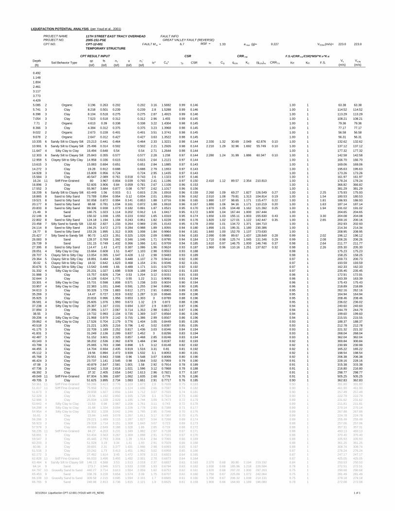
LIQUEFACTION POTENTIAL ANALYSIS (per Youd et al., 2001)
PROJECT NAME 11TH STREET EAST TRACY OVERHEAD FAULT INFOPROJECT NO. 2005-151-PSE GREAT VALLEY FAULT (REVERSE)CPT NO. CPT-12-001 FAULT M w = 6.7 MSF = 1.33 a max (g)= 0.227 VS30m(m/s)= 223.0 223.0
TEMPORARY STRUCTURE
Depth qc fs v u v'(ft) (tsf) (tsf) (tsf) (tsf) (tsf)
0.4921.1481.8042.4613.1173.7734.4295.085 2 Organic 3.196 0.263 0.202 0.202 3.16 1.5692 0.99 0.146 1.00 1 63.38 63.385.741 3 Clay 8.218 0.501 0.239 0.239 2.8 1.5288 0.99 0.146 1.00 1 114.52 114.526.398 3 Clay 8.104 0.518 0.275 0.275 2.87 1.4915 0.99 0.146 1.00 1 113.29 113.297.054 3 Clay 7.523 0.518 0.312 0.312 2.96 1.455 0.99 0.145 1.00 1 108.21 108.217.71 2 Organic 4.613 0.39 0.338 0.338 3.22 1.4304 0.98 0.145 1.00 1 79.36 79.368.366 3 Clay 4.384 0.312 0.375 0.375 3.23 1.3968 0.98 0.145 1.00 1 77.17 77.179.022 2 Organic 2.673 0.228 0.401 0.401 3.51 1.3741 0.98 0.145 1.00 1 56.58 56.589.678 2 Organic 2.647 0.312 0.427 0.427 3.63 1.3522 0.98 0.145 1.00 1 56.31 56.3110.335 6 Sandy Silt to Clayey Silt 23.213 0.441 0.464 0.464 2.33 1.3221 0.98 0.144 2.330 1.32 30.69 2.049 62.876 0.10 1.00 1 132.62 132.6210.991 6 Sandy Silt to Clayey Silt 25.496 0.314 0.502 0.502 2.21 1.2926 0.98 0.144 2.210 1.29 32.96 1.692 55.749 0.10 1.00 1 137.12 137.1211.647 4 Silty Clay to Clay 16.494 0.648 0.54 0.54 2.71 1.2644 0.98 0.144 1.00 1 177.32 177.3212.303 6 Sandy Silt to Clayey Silt 25.843 0.355 0.577 0.577 2.28 1.238 0.97 0.144 2.280 1.24 31.99 1.886 60.347 0.10 1.00 1 142.58 142.5812.959 5 Clayey Silt to Silty Clay 14.958 0.336 0.615 0.615 2.64 1.2121 0.97 0.144 1.00 1 166.70 166.7013.615 3 Clay 15.083 0.694 0.651 0.651 2.84 1.1885 0.97 0.143 1.00 1 169.06 169.0614.272 3 Clay 19.28 0.912 0.688 0.688 2.79 1.1653 0.97 0.143 1.00 1 195.63 195.6314.928 3 Clay 15.809 0.956 0.724 0.724 2.95 1.1435 0.97 0.143 1.00 1 173.26 173.2615.584 3 Clay 40.547 2.089 0.761 0.018 0.743 2.6 1.1323 0.97 0.146 1.00 1 161.97 161.9716.24 11 Sitff Fine-Grained 80 3.967 0.804 0.039 0.765 2.41 1.1196 0.97 0.150 2.410 1.12 89.57 2.354 210.810 1.00 1 178.24 178.2416.896 3 Clay 52.605 3.906 0.84 0.059 0.781 2.67 1.1106 0.96 0.153 1.00 1 366.82 366.8217.552 3 Clay 55.967 3.684 0.877 0.08 0.797 2.62 1.1017 0.96 0.156 1.00 1 381.29 381.2918.209 6 Sandy Silt to Clayey Silt 63.449 1.56 0.915 0.1 0.815 2.26 1.0918 0.96 0.159 2.260 1.09 69.27 1.827 126.549 0.27 1.00 1 2.25 175.93 175.9318.865 8 Sand to Silty Sand 73.789 0.894 0.954 0.12 0.834 2.01 1.0816 0.96 0.162 2.010 1.08 79.81 1.313 104.814 0.19 1.00 1 1.54 180.53 180.5319.521 8 Sand to Silty Sand 92.058 0.872 0.994 0.141 0.853 1.88 1.0716 0.96 0.165 1.880 1.07 98.65 1.171 115.477 0.22 1.00 1 1.81 186.93 186.9320.177 8 Sand to Silty Sand 88.68 0.781 1.034 0.161 0.872 1.88 1.0618 0.96 0.167 1.880 1.06 94.16 1.171 110.219 0.20 1.00 1 1.63 187.14 187.1420.833 8 Sand to Silty Sand 99.306 0.938 1.073 0.182 0.891 1.87 1.0521 0.95 0.170 1.870 1.05 104.48 1.162 121.392 0.25 1.00 1 1.94 191.02 191.0221.49 9 Sand 160.75 1.023 1.114 0.202 0.912 1.6 1.0417 0.95 0.172 1.600 1.04 167.44 1.000 167.444 1.00 1 204.65 204.6522.146 9 Sand 150.32 1.038 1.155 0.223 0.932 1.65 1.0319 0.95 0.174 1.650 1.03 155.11 1.003 155.630 0.43 1.00 1 3.30 204.08 204.0822.802 8 Sand to Silty Sand 124.18 1.194 1.194 0.243 0.951 1.82 1.0228 0.95 0.176 1.820 1.02 127.01 1.122 142.447 0.35 1.00 1 2.65 200.16 200.1623.458 7 Silty Sand to Sandy Silt 132.82 2.827 1.233 0.264 0.969 2.05 1.0143 0.95 0.178 2.050 1.01 134.72 1.371 184.710 1.00 1 202.93 202.9324.114 8 Sand to Silty Sand 194.25 3.472 1.273 0.284 0.988 1.89 1.0055 0.94 0.180 1.890 1.01 195.31 1.180 230.386 1.00 1 214.34 214.3424.77 8 Sand to Silty Sand 153.26 1.895 1.312 0.305 1.008 1.84 0.9964 0.94 0.181 1.840 1.00 152.70 1.137 173.630 1.00 1 208.95 208.9525.427 7 Silty Sand to Sandy Silt 90.73 1.423 1.351 0.325 1.026 2.09 0.9883 0.94 0.183 2.090 0.99 89.67 1.437 128.849 0.28 0.99 1 2.02 196.12 196.1226.083 9 Sand 128.37 0.769 1.392 0.346 1.046 1.71 0.9795 0.94 0.184 1.710 0.98 125.74 1.045 131.346 0.29 0.99 1 2.08 206.26 206.2626.739 9 Sand 151.15 0.749 1.432 0.366 1.066 1.61 0.9709 0.94 0.185 1.610 0.97 146.75 1.000 146.746 0.37 0.98 1 2.64 211.77 211.7727.395 8 Sand to Silty Sand 114.47 1.43 1.472 0.387 1.086 1.96 0.9624 0.93 0.187 1.960 0.96 110.16 1.251 137.827 0.32 0.98 1 2.26 205.30 205.3028.051 4 Silty Clay to Clay 15.664 0.608 1.51 0.407 1.103 2.98 0.9553 0.93 0.188 0.98 1 175.23 175.2328.707 5 Clayey Silt to Silty Clay 13.054 0.395 1.547 0.428 1.12 2.98 0.9483 0.93 0.189 0.98 1 158.25 158.2529.364 5 Clayey Silt to Silty Clay 18.891 0.484 1.585 0.448 1.137 2.79 0.9414 0.92 0.190 0.97 1 200.73 200.7330.02 5 Clayey Silt to Silty Clay 18.02 0.642 1.623 0.468 1.154 2.91 0.9346 0.92 0.191 0.97 1 193.59 193.5930.676 5 Clayey Silt to Silty Clay 13.542 0.448 1.66 0.489 1.171 3.01 0.9279 0.92 0.192 0.97 1 162.33 162.3331.332 4 Silty Clay to Clay 25.231 1.027 1.698 0.509 1.188 2.84 0.9213 0.91 0.193 0.97 1 235.45 235.4531.988 3 Clay 15.757 0.826 1.734 0.53 1.204 3.12 0.9151 0.91 0.193 0.96 1 172.91 172.9132.644 3 Clay 14.128 0.624 1.771 0.55 1.22 3.11 0.9091 0.91 0.194 0.96 1 163.39 163.3933.301 4 Silty Clay to Clay 15.731 0.598 1.808 0.571 1.238 3.03 0.9024 0.90 0.194 0.96 1 175.43 175.4333.957 4 Silty Clay to Clay 22.383 1.031 1.846 0.591 1.255 2.94 0.8961 0.90 0.195 0.96 1 218.89 218.8934.613 3 Clay 30.326 1.729 1.883 0.612 1.271 2.91 0.8903 0.89 0.195 0.95 1 262.16 262.1635.269 3 Clay 14.47 0.727 1.919 0.632 1.287 3.16 0.8846 0.89 0.196 0.95 1 164.94 164.9435.925 3 Clay 20.816 0.996 1.956 0.653 1.303 3 0.8789 0.88 0.196 0.95 1 208.46 208.4636.581 4 Silty Clay to Clay 25.605 1.076 1.993 0.673 1.32 2.9 0.873 0.88 0.196 0.95 1 236.02 236.0237.238 4 Silty Clay to Clay 26.367 1.167 2.031 0.694 1.337 2.9 0.8672 0.87 0.196 0.94 1 240.60 240.6037.894 3 Clay 27.395 1.577 2.067 0.714 1.353 2.98 0.8617 0.87 0.196 0.94 1 244.79 244.7938.55 3 Clay 19.732 0.993 2.104 0.735 1.369 3.07 0.8564 0.86 0.196 0.94 1 199.60 199.6039.206 4 Silty Clay to Clay 21.968 0.979 2.142 0.755 1.386 2.99 0.8507 0.86 0.196 0.94 1 215.55 215.5539.862 4 Silty Clay to Clay 17.526 0.704 2.179 0.776 1.404 3.05 0.8449 0.85 0.195 0.93 1 188.37 188.3740.518 3 Clay 21.221 1.005 2.216 0.796 1.42 3.02 0.8397 0.85 0.195 0.93 1 212.78 212.7841.175 3 Clay 22.709 1.189 2.252 0.817 1.436 3.03 0.8346 0.84 0.194 0.93 1 221.32 221.3241.831 3 Clay 31.249 2.136 2.289 0.837 1.452 3 0.8296 0.83 0.194 0.93 1 268.04 268.0442.487 3 Clay 51.152 3.601 2.325 0.857 1.468 2.85 0.8246 0.83 0.194 0.93 1 362.04 362.0443.143 3 Clay 38.202 2.536 2.362 0.878 1.484 2.94 0.8197 0.82 0.193 0.92 1 300.84 300.8443.799 3 Clay 25.065 1.783 2.398 0.898 1.5 3.12 0.8148 0.82 0.192 0.92 1 230.99 230.9944.455 3 Clay 14.704 0.934 2.435 0.919 1.516 3.31 0.81 0.81 0.192 0.92 1 165.22 165.2245.112 3 Clay 19.56 0.894 2.472 0.939 1.532 3.1 0.8053 0.80 0.191 0.92 1 198.54 198.5445.768 3 Clay 20.551 0.943 2.508 0.96 1.548 3.07 0.8006 0.80 0.190 0.92 1 206.38 206.3846.424 3 Clay 23.737 1.141 2.545 0.98 1.564 3.02 0.7959 0.79 0.190 0.91 1 228.16 228.1647.08 3 Clay 40.879 2.647 2.581 1.001 1.58 2.92 0.7914 0.78 0.189 0.91 1 315.38 315.3847.736 3 Clay 22.642 1.318 2.618 1.021 1.596 3.12 0.7868 0.78 0.188 0.91 1 216.80 216.8048.392 3 Clay 37.32 2.405 2.654 1.042 1.613 2.96 0.7821 0.77 0.187 0.91 1 298.77 298.7749.049 11 Sitff Fine-Grained 87.004 5.386 2.697 1.062 1.635 2.68 0.776 0.76 0.186 0.91 1 505.25 505.2549.705 3 Clay 51.625 3.895 2.734 1.083 1.651 2.91 0.7717 0.76 0.185 0.90 1 362.83 362.8350.361 11 Sitff Fine-Grained 58.286 3.413 2.776 1.103 1.673 2.8 0.7658 0.75 0.183 0.90 1 391.80 391.8051.017 11 Sitff Fine-Grained 75.958 3.711 2.819 1.124 1.696 2.66 0.7597 0.74 0.182 0.90 1 461.90 461.9051.673 3 Clay 29.838 1.927 2.856 1.144 1.712 3.07 0.7555 0.74 0.181 0.90 1 257.49 257.4952.329 3 Clay 23.56 1.192 2.892 1.165 1.728 3.1 0.7514 0.73 0.180 0.90 1 222.79 222.7952.986 3 Clay 25.034 1.338 2.929 1.185 1.744 3.09 0.7473 0.72 0.179 0.89 1 231.62 231.6253.642 4 Silty Clay to Clay 21.63 0.98 2.967 1.206 1.761 3.11 0.743 0.72 0.178 0.89 1 211.81 211.8154.298 4 Silty Clay to Clay 31.68 1.334 3.004 1.226 1.778 2.93 0.7388 0.71 0.177 0.89 1 270.14 270.1454.954 4 Silty Clay to Clay 31.302 1.328 3.042 1.246 1.795 2.95 0.7346 0.70 0.176 0.89 1 267.88 267.8855.61 3 Clay 23.84 1.449 3.078 1.267 1.811 3.17 0.7307 0.70 0.175 0.89 1 224.78 224.7856.266 3 Clay 29.221 1.489 3.115 1.287 1.827 3.04 0.7268 0.69 0.174 0.89 1 255.49 255.4956.923 3 Clay 29.319 1.714 3.151 1.308 1.843 3.07 0.723 0.69 0.173 0.88 1 257.06 257.0657.579 3 Clay 49.684 2.649 3.188 1.328 1.86 2.85 0.719 0.68 0.172 0.88 1 357.31 357.3158.235 11 Sitff Fine-Grained 84.27 4.203 3.231 1.349 1.882 2.67 0.7138 0.67 0.171 0.88 1 493.13 493.1358.891 3 Clay 53.404 3.563 3.267 1.369 1.898 2.91 0.7101 0.67 0.170 0.88 1 370.40 370.4059.547 3 Clay 45.445 2.793 3.304 1.39 1.914 2.94 0.7065 0.66 0.169 0.88 1 335.93 335.9360.203 3 Clay 51.028 3.19 3.34 1.41 1.93 2.91 0.7029 0.66 0.168 0.88 1 361.25 361.2560.86 3 Clay 39.691 2.31 3.377 1.431 1.946 2.98 0.6993 0.65 0.167 0.88 1 308.74 308.7461.516 3 Clay 33.242 1.73 3.413 1.451 1.962 3.02 0.6958 0.65 0.166 0.87 1 276.24 276.2462.172 3 Clay 27.462 1.614 3.45 1.472 1.978 3.13 0.6923 0.64 0.165 0.87 1 247.17 247.1762.828 11 Sitff Fine-Grained 66.033 3.498 3.493 1.492 2.001 2.78 0.6873 0.64 0.164 0.87 1 425.05 425.0563.484 6 Sandy Silt to Clayey Silt 146.13 4.588 3.53 1.513 2.018 2.37 0.6837 0.63 0.163 2.370 0.68 99.90 2.194 219.192 0.84 1 250.53 250.5364.14 9 Sand 273.7 3.946 3.571 1.533 2.038 1.93 0.6794 0.63 0.162 1.930 0.68 185.96 1.218 226.584 0.78 1 272.51 272.5164.797 10 Gravelly Sand to Sand 440.27 3.714 3.613 1.554 2.059 1.62 0.6751 0.62 0.161 1.620 0.68 297.20 1.000 297.203 0.75 1 290.68 290.6865.453 9 Sand 336.78 3.228 3.654 1.574 2.08 1.75 0.6707 0.62 0.160 1.750 0.67 225.89 1.072 242.064 0.75 1 281.49 281.4966.109 10 Gravelly Sand to Sand 309.58 2.215 3.695 1.594 2.101 1.7 0.6665 0.61 0.160 1.700 0.67 206.32 1.038 214.131 0.75 1 279.18 279.1866.765 9 Sand 248.98 2.813 3.736 1.615 2.121 1.9 0.6625 0.61 0.159 1.900 0.66 164.93 1.189 196.080 0.78 1 272.08 272.08
CPT RESULT INPUT CSR CRR 7.5 F.S.=(CRR 7.5 /CSR)*MSF*K *K
Soil Behavior Type Ic* CN* d CSR Ic CQ qc1N KC (qc1N)cs CRR7.5 K K F.S.Vs
(m/s)Vs,liq
(m/s)
3/21/2014 Liquefaction CPT-12-001 (YOUD with VS_NEW) 1 of 1
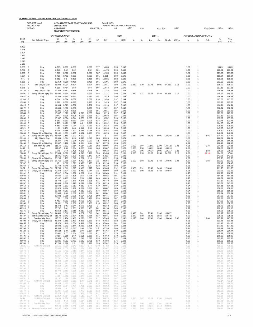
LIQUEFACTION POTENTIAL ANALYSIS (per Youd et al., 2001)
PROJECT NAME 11TH STREET EAST TRACY OVERHEAD FAULT INFOPROJECT NO. 2005-151-PSE GREAT VALLEY FAULT (REVERSE)CPT NO. CPT-12-002 FAULT M w = 6.7 MSF = 1.33 a max (g)= 0.227 VS30m(m/s)= 200.6 196.6
TEMPORARY STRUCTURE
Depth qc fs v u v'(ft) (tsf) (tsf) (tsf) (tsf) (tsf)
0.4921.1481.8042.4613.1173.7734.4295.085 3 Clay 6.615 0.233 0.283 0.283 2.77 1.4835 0.99 0.146 1.00 1 99.89 99.895.741 3 Clay 8.748 0.42 0.32 0.32 2.81 1.4474 0.99 0.146 1.00 1 119.09 119.096.398 3 Clay 7.861 0.368 0.356 0.356 2.87 1.4139 0.99 0.146 1.00 1 111.35 111.357.054 3 Clay 8.426 0.432 0.393 0.393 2.91 1.381 0.99 0.145 1.00 1 116.34 116.347.71 3 Clay 8.862 0.5 0.429 0.429 2.95 1.3505 0.98 0.145 1.00 1 120.03 120.038.366 3 Clay 20.354 0.956 0.466 0.466 2.65 1.3205 0.98 0.145 1.00 1 202.23 202.239.022 4 Silty Clay to Clay 23.804 0.924 0.504 0.504 2.56 1.2911 0.98 0.145 2.560 1.29 30.73 3.091 94.982 0.16 1.00 1 136.00 136.009.678 3 Clay 8.115 0.454 0.54 0.54 3.07 1.2644 0.98 0.145 1.00 1 113.11 113.1110.335 4 Silty Clay to Clay 19.363 0.742 0.578 0.578 2.67 1.2373 0.98 0.144 1.00 1 195.56 195.5610.991 6 Sandy Silt to Clayey Silt 32.692 0.954 0.615 0.615 2.44 1.2121 0.98 0.144 2.440 1.21 39.63 2.483 98.398 0.17 1.00 1 149.57 149.5711.647 3 Clay 16.385 0.993 0.652 0.652 2.91 1.1879 0.98 0.144 1.00 1 176.38 176.3812.303 3 Clay 8.514 0.674 0.688 0.688 3.24 1.1653 0.97 0.144 1.00 1 117.03 117.0312.959 3 Clay 9.287 0.559 0.725 0.725 3.14 1.1429 0.97 0.144 1.00 1 123.73 123.7313.615 3 Clay 14.984 0.823 0.762 0.762 2.96 1.1213 0.97 0.143 1.00 1 166.91 166.9114.272 3 Clay 17.049 1.098 0.798 0.798 2.98 1.1011 0.97 0.143 1.00 1 180.74 180.7414.928 3 Clay 22.295 1.478 0.835 0.835 2.91 1.0811 0.97 0.143 1.00 1 213.99 213.9915.584 3 Clay 16.867 1.221 0.871 0.018 0.853 3.04 1.0716 0.97 0.146 1.00 1 179.61 179.6116.24 3 Clay 10.47 0.628 0.908 0.039 0.869 3.17 1.0633 0.97 0.149 1.00 1 133.12 133.1216.896 3 Clay 10.967 0.604 0.944 0.059 0.885 3.14 1.0552 0.96 0.152 1.00 1 137.07 137.0717.552 3 Clay 9.163 0.553 0.981 0.08 0.901 3.24 1.0471 0.96 0.155 1.00 1 122.48 122.4818.209 3 Clay 8.203 0.471 1.017 0.1 0.917 3.29 1.0392 0.96 0.157 1.00 1 114.25 114.2518.865 3 Clay 9.853 0.564 1.054 0.12 0.933 3.22 1.0314 0.96 0.160 1.00 1 128.19 128.1919.521 3 Clay 11.81 0.751 1.09 0.141 0.95 3.18 1.0233 0.96 0.162 1.00 1 143.65 143.6520.177 3 Clay 9.905 0.685 1.127 0.161 0.966 3.28 1.0157 0.96 0.165 1.00 1 128.60 128.6020.833 5 Clayey Silt to Silty Clay 27.182 1.053 1.165 0.182 0.983 2.74 1.0078 0.95 0.167 1.00 1 242.39 242.3921.49 6 Sandy Silt to Clayey Silt 38.923 1.181 1.202 0.202 1 2.56 1 0.95 0.169 2.560 1.00 38.92 3.091 120.294 0.24 1.00 1 1.91 174.47 174.4722.146 4 Silty Clay to Clay 24.359 1.074 1.24 0.223 1.017 2.83 0.9923 0.95 0.171 1.00 1 226.01 226.0122.802 3 Clay 15.285 0.92 1.276 0.243 1.033 3.1 0.9852 0.95 0.173 0.99 1 168.65 168.6523.458 5 Clayey Silt to Silty Clay 33.507 1.198 1.314 0.264 1.05 2.67 0.9778 0.95 0.175 0.99 1 276.13 276.1324.114 8 Sand to Silty Sand 116.45 1.312 1.354 0.284 1.069 1.92 0.9696 0.94 0.177 1.920 0.97 112.91 1.208 136.422 0.32 0.98 1 2.34 204.85 204.8524.77 9 Sand 172.07 1.05 1.394 0.305 1.09 1.63 0.9607 0.94 0.178 1.630 0.96 165.31 1.000 165.310 0.97 1 216.66 216.6625.427 9 Sand 110.5 0.63 1.435 0.325 1.11 1.77 0.9524 0.94 0.179 1.770 0.95 105.24 1.085 114.217 0.22 0.97 1 1.58 205.55 205.5526.083 6 Sandy Silt to Clayey Silt 30.539 0.662 1.473 0.346 1.127 2.59 0.9454 0.94 0.181 2.590 0.95 28.87 3.266 94.298 0.16 0.98 1 (1.14) 174.66 57.6626.739 3 Clay 11.581 0.543 1.509 0.366 1.143 3.19 0.939 0.94 0.182 0.97 1 142.58 142.5827.395 5 Clayey Silt to Silty Clay 30.295 1.191 1.547 0.387 1.16 2.77 0.9322 0.93 0.184 0.97 1 259.70 259.7028.051 6 Sandy Silt to Clayey Silt 57.716 1.899 1.584 0.407 1.177 2.5 0.9255 0.93 0.185 2.500 0.93 53.42 2.768 147.885 0.38 0.97 1 2.66 191.90 191.9028.707 3 Clay 15 0.812 1.621 0.428 1.193 3.15 0.9193 0.93 0.186 0.97 1 166.49 166.4929.364 3 Clay 12.748 0.845 1.658 0.448 1.21 3.28 0.9129 0.92 0.187 0.96 1 150.28 150.2830.02 6 Sandy Silt to Clayey Silt 77.733 2.611 1.695 0.468 1.227 2.43 0.9065 0.92 0.188 2.430 0.91 70.46 2.439 171.860 0.96 1 201.73 201.7330.676 5 Clayey Silt to Silty Clay 79.279 3.374 1.733 0.489 1.244 2.5 0.9002 0.92 0.189 2.500 0.90 71.36 2.768 197.567 0.96 1 202.99 202.9931.332 3 Clay 30.617 2.014 1.769 0.509 1.26 2.95 0.8943 0.91 0.189 0.95 1 260.77 260.7731.988 3 Clay 17.635 1.203 1.806 0.53 1.276 3.17 0.8885 0.91 0.190 0.95 1 184.38 184.3832.644 3 Clay 10.107 0.705 1.842 0.55 1.292 3.43 0.8828 0.91 0.191 0.95 1 129.82 129.8233.301 3 Clay 15.772 1.007 1.879 0.571 1.308 3.21 0.8772 0.90 0.191 0.95 1 171.89 171.8933.957 3 Clay 44.008 2.316 1.915 0.591 1.324 2.78 0.8716 0.90 0.192 0.95 1 327.63 327.6334.613 3 Clay 18.538 1.312 1.952 0.612 1.34 3.19 0.8661 0.89 0.192 0.94 1 190.18 190.1835.269 3 Clay 13.926 0.974 1.989 0.632 1.356 3.31 0.8607 0.89 0.192 0.94 1 158.83 158.8335.925 3 Clay 13.428 0.983 2.025 0.653 1.372 3.34 0.8554 0.88 0.193 0.94 1 155.36 155.3636.581 3 Clay 25.548 1.46 2.062 0.673 1.388 3.01 0.8501 0.88 0.193 0.94 1 232.94 232.9437.238 3 Clay 29.932 1.855 2.098 0.694 1.405 2.98 0.8445 0.87 0.193 0.93 1 257.33 257.3337.894 3 Clay 17.76 1.318 2.135 0.714 1.421 3.24 0.8394 0.87 0.193 0.93 1 185.37 185.3738.55 3 Clay 9.453 0.862 2.171 0.735 1.437 3.6 0.8343 0.86 0.192 0.93 1 124.65 124.6539.206 3 Clay 21.361 1.606 2.208 0.755 1.453 3.18 0.8292 0.86 0.192 0.93 1 208.28 208.2839.862 3 Clay 31.473 2.05 2.244 0.776 1.469 3 0.8243 0.85 0.192 0.93 1 265.72 265.7240.518 3 Clay 30.752 2.01 2.281 0.796 1.485 3.01 0.8194 0.85 0.192 0.92 1 262.16 262.1641.175 3 Clay 45.653 3.127 2.318 0.817 1.501 2.89 0.8145 0.84 0.192 0.92 1 335.56 335.5641.831 6 Sandy Silt to Clayey Silt 94.403 3.016 2.355 0.837 1.518 2.42 0.8094 0.83 0.191 2.420 0.81 76.41 2.396 183.072 0.91 1 219.12 219.1242.487 7 Silty Sand to Sandy Silt 113.74 2.642 2.394 0.857 1.536 2.27 0.8041 0.83 0.190 2.270 0.80 91.45 1.856 169.746 0.90 1 225.21 225.2143.143 8 Sand to Silty Sand 120.72 2.134 2.433 0.878 1.555 2.17 0.7985 0.82 0.190 2.170 0.80 96.40 1.596 153.896 0.42 0.90 1 2.64 227.72 227.7243.799 5 Clayey Silt to Silty Clay 45.279 1.681 2.471 0.898 1.573 2.73 0.7934 0.82 0.189 0.91 1 333.85 333.8544.455 3 Clay 17.376 1.219 2.508 0.919 1.589 3.29 0.7888 0.81 0.188 0.91 1 183.13 183.1345.112 3 Clay 16.504 1.292 2.544 0.939 1.605 3.34 0.7843 0.80 0.188 0.91 1 177.32 177.3245.768 3 Clay 42.333 2.505 2.581 0.96 1.621 2.9 0.7799 0.80 0.187 0.91 1 320.19 320.1946.424 3 Clay 37.528 2.39 2.617 0.98 1.637 2.97 0.7755 0.79 0.186 0.91 1 296.74 296.7447.08 3 Clay 26.601 1.77 2.654 1.001 1.653 3.11 0.7711 0.78 0.185 0.90 1 239.19 239.1947.736 3 Clay 18.18 1.385 2.69 1.021 1.669 3.31 0.7668 0.78 0.185 0.90 1 188.30 188.3048.392 3 Clay 14.543 0.79 2.727 1.042 1.685 3.33 0.7626 0.77 0.184 0.90 1 163.75 163.7549.049 3 Clay 13.926 0.852 2.763 1.062 1.701 3.38 0.7584 0.76 0.183 0.90 1 159.55 159.5549.705 3 Clay 40.703 2.878 2.8 1.083 1.717 2.99 0.7542 0.76 0.182 0.90 1 312.55 312.5550.361 11 Sitff Fine-Grained 60.616 3.386 2.843 1.103 1.74 2.78 0.7483 0.75 0.181 0.90 1 400.85 400.8551.017 3 Clay 29.688 2.009 2.879 1.124 1.756 3.1 0.7442 0.74 0.180 0.89 1 255.98 255.9851.673 3 Clay 20.115 1.432 2.916 1.144 1.772 3.28 0.7402 0.74 0.179 0.89 1 200.86 200.8652.329 3 Clay 19.021 1.158 2.952 1.165 1.788 3.26 0.7363 0.73 0.178 0.89 1 194.29 194.2952.986 3 Clay 22.217 1.463 2.989 1.185 1.804 3.22 0.7324 0.72 0.177 0.89 1 214.17 214.1753.642 3 Clay 26.751 1.542 3.026 1.206 1.82 3.11 0.7285 0.72 0.176 0.89 1 240.54 240.5454.298 3 Clay 31.369 1.969 3.062 1.226 1.836 3.07 0.7246 0.71 0.175 0.89 1 265.67 265.6754.954 3 Clay 21.148 1.443 3.099 1.246 1.852 3.26 0.7208 0.70 0.174 0.88 1 207.48 207.4855.61 3 Clay 18.818 1.284 3.135 1.267 1.868 3.32 0.7171 0.70 0.173 0.88 1 193.01 193.0156.266 3 Clay 26.451 1.82 3.172 1.287 1.884 3.18 0.7134 0.69 0.172 0.88 1 238.68 238.6856.923 3 Clay 35.774 2.553 3.208 1.308 1.9 3.08 0.7097 0.69 0.171 0.88 1 288.14 288.1457.579 3 Clay 21.729 1.582 3.245 1.328 1.916 3.29 0.706 0.68 0.170 0.88 1 210.96 210.9658.235 3 Clay 14.05 1.051 3.281 1.349 1.933 3.5 0.7022 0.67 0.169 0.88 1 160.69 160.6958.891 3 Clay 23.197 1.698 3.318 1.369 1.949 3.27 0.6986 0.67 0.168 0.88 1 219.96 219.9659.547 11 Sitff Fine-Grained 60.927 3.698 3.361 1.39 1.971 2.85 0.6938 0.66 0.167 0.87 1 402.14 402.1460.203 3 Clay 32.059 2.471 3.397 1.41 1.987 3.16 0.6903 0.66 0.166 0.87 1 268.73 268.7360.86 3 Clay 24.982 2.014 3.434 1.431 2.003 3.28 0.6869 0.65 0.165 0.87 1 229.90 229.9061.516 3 Clay 17.469 1.4 3.47 1.451 2.019 3.44 0.6834 0.65 0.164 0.87 1 183.85 183.8562.172 3 Clay 22.201 1.756 3.507 1.472 2.035 3.33 0.6801 0.64 0.163 0.87 1 213.99 213.9962.828 3 Clay 26.928 2.27 3.543 1.492 2.051 3.27 0.6767 0.64 0.162 0.87 1 241.44 241.4463.484 11 Sitff Fine-Grained 92.852 5.304 3.586 1.513 2.074 2.71 0.672 0.63 0.161 0.86 1 523.90 523.9064.14 11 Sitff Fine-Grained 124.48 6.256 3.629 1.533 2.096 2.58 0.6675 0.63 0.160 2.580 0.67 83.08 3.206 266.405 0.86 1 247.83 247.8364.797 3 Clay 52.75 4.13 3.666 1.554 2.112 3 0.6643 0.62 0.160 0.86 1 367.22 367.2265.453 8 Sand to Silty Sand 210.2 3.069 3.705 1.574 2.131 2.03 0.6605 0.62 0.159 2.030 0.66 138.83 1.341 186.196 0.80 1 266.50 266.5066.109 9 Sand 284.48 2.685 3.746 1.594 2.152 1.81 0.6563 0.61 0.158 1.810 0.66 186.71 1.114 208.001 0.76 1 277.93 277.9366.765 10 Gravelly Sand to Sand 375.97 3.156 3.788 1.615 2.173 1.69 0.6522 0.61 0.157 1.690 0.65 245.22 1.031 252.842 0.73 1 288.93 288.93
CQ qc1N KC (qc1N)cs CRR7.5 K K F.S.Vs
(m/s)Vs,liq
(m/s)
CPT RESULT INPUT CSR CRR 7.5 F.S.=(CRR 7.5 /CSR)*MSF*K *K
Soil Behavior Type Ic* CN* d CSR Ic
3/21/2014 Liquefaction CPT-12-002 (YOUD with VS_NEW) 1 of 1
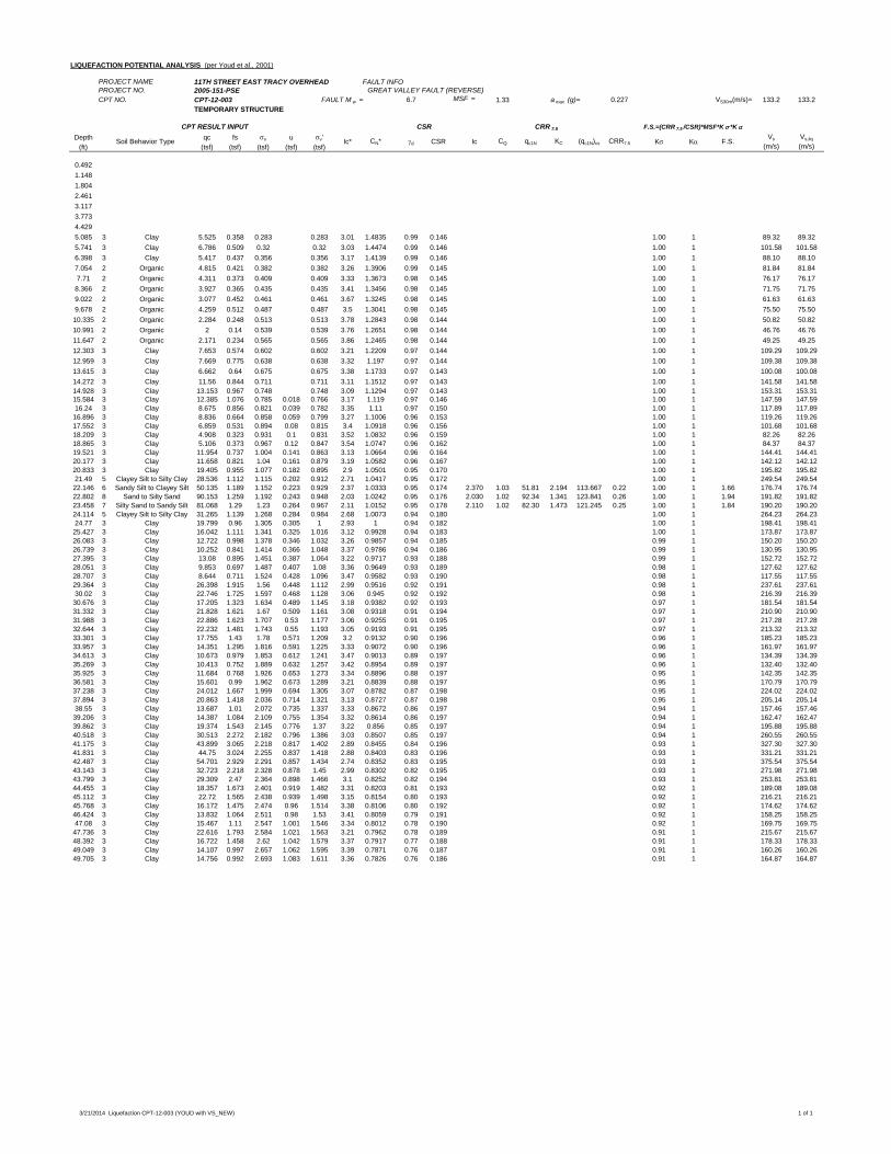
LIQUEFACTION POTENTIAL ANALYSIS (per Youd et al., 2001)
PROJECT NAME 11TH STREET EAST TRACY OVERHEAD FAULT INFOPROJECT NO. 2005-151-PSE GREAT VALLEY FAULT (REVERSE)CPT NO. CPT-12-003 FAULT M w = 6.7 MSF = 1.33 a max (g)= 0.227 VS30m(m/s)= 133.2 133.2
TEMPORARY STRUCTURE
Depth qc fs v u v'(ft) (tsf) (tsf) (tsf) (tsf) (tsf)
0.4921.1481.8042.4613.1173.7734.4295.085 3 Clay 5.525 0.358 0.283 0.283 3.01 1.4835 0.99 0.146 1.00 1 89.32 89.325.741 3 Clay 6.786 0.509 0.32 0.32 3.03 1.4474 0.99 0.146 1.00 1 101.58 101.586.398 3 Clay 5.417 0.437 0.356 0.356 3.17 1.4139 0.99 0.146 1.00 1 88.10 88.107.054 2 Organic 4.815 0.421 0.382 0.382 3.26 1.3906 0.99 0.145 1.00 1 81.84 81.847.71 2 Organic 4.311 0.373 0.409 0.409 3.33 1.3673 0.98 0.145 1.00 1 76.17 76.178.366 2 Organic 3.927 0.365 0.435 0.435 3.41 1.3456 0.98 0.145 1.00 1 71.75 71.759.022 2 Organic 3.077 0.452 0.461 0.461 3.67 1.3245 0.98 0.145 1.00 1 61.63 61.639.678 2 Organic 4.259 0.512 0.487 0.487 3.5 1.3041 0.98 0.145 1.00 1 75.50 75.5010.335 2 Organic 2.284 0.248 0.513 0.513 3.78 1.2843 0.98 0.144 1.00 1 50.82 50.8210.991 2 Organic 2 0.14 0.539 0.539 3.76 1.2651 0.98 0.144 1.00 1 46.76 46.7611.647 2 Organic 2.171 0.234 0.565 0.565 3.86 1.2465 0.98 0.144 1.00 1 49.25 49.2512.303 3 Clay 7.653 0.574 0.602 0.602 3.21 1.2209 0.97 0.144 1.00 1 109.29 109.2912.959 3 Clay 7.669 0.775 0.638 0.638 3.32 1.197 0.97 0.144 1.00 1 109.38 109.3813.615 3 Clay 6.662 0.64 0.675 0.675 3.38 1.1733 0.97 0.143 1.00 1 100.08 100.0814.272 3 Clay 11.56 0.844 0.711 0.711 3.11 1.1512 0.97 0.143 1.00 1 141.58 141.5814.928 3 Clay 13.153 0.967 0.748 0.748 3.09 1.1294 0.97 0.143 1.00 1 153.31 153.3115.584 3 Clay 12.385 1.076 0.785 0.018 0.766 3.17 1.119 0.97 0.146 1.00 1 147.59 147.5916.24 3 Clay 8.675 0.856 0.821 0.039 0.782 3.35 1.11 0.97 0.150 1.00 1 117.89 117.8916.896 3 Clay 8.836 0.664 0.858 0.059 0.799 3.27 1.1006 0.96 0.153 1.00 1 119.26 119.2617.552 3 Clay 6.859 0.531 0.894 0.08 0.815 3.4 1.0918 0.96 0.156 1.00 1 101.68 101.6818.209 3 Clay 4.908 0.323 0.931 0.1 0.831 3.52 1.0832 0.96 0.159 1.00 1 82.26 82.2618.865 3 Clay 5.106 0.373 0.967 0.12 0.847 3.54 1.0747 0.96 0.162 1.00 1 84.37 84.3719.521 3 Clay 11.954 0.737 1.004 0.141 0.863 3.13 1.0664 0.96 0.164 1.00 1 144.41 144.4120.177 3 Clay 11.658 0.821 1.04 0.161 0.879 3.19 1.0582 0.96 0.167 1.00 1 142.12 142.1220.833 3 Clay 19.405 0.955 1.077 0.182 0.895 2.9 1.0501 0.95 0.170 1.00 1 195.82 195.8221.49 5 Clayey Silt to Silty Clay 28.536 1.112 1.115 0.202 0.912 2.71 1.0417 0.95 0.172 1.00 1 249.54 249.5422.146 6 Sandy Silt to Clayey Silt 50.135 1.189 1.152 0.223 0.929 2.37 1.0333 0.95 0.174 2.370 1.03 51.81 2.194 113.667 0.22 1.00 1 1.66 176.74 176.7422.802 8 Sand to Silty Sand 90.153 1.259 1.192 0.243 0.948 2.03 1.0242 0.95 0.176 2.030 1.02 92.34 1.341 123.841 0.26 1.00 1 1.94 191.82 191.8223.458 7 Silty Sand to Sandy Silt 81.068 1.29 1.23 0.264 0.967 2.11 1.0152 0.95 0.178 2.110 1.02 82.30 1.473 121.245 0.25 1.00 1 1.84 190.20 190.2024.114 5 Clayey Silt to Silty Clay 31.265 1.139 1.268 0.284 0.984 2.68 1.0073 0.94 0.180 1.00 1 264.23 264.2324.77 3 Clay 19.799 0.96 1.305 0.305 1 2.93 1 0.94 0.182 1.00 1 198.41 198.4125.427 3 Clay 16.042 1.111 1.341 0.325 1.016 3.12 0.9928 0.94 0.183 1.00 1 173.87 173.8726.083 3 Clay 12.722 0.998 1.378 0.346 1.032 3.26 0.9857 0.94 0.185 0.99 1 150.20 150.2026.739 3 Clay 10.252 0.841 1.414 0.366 1.048 3.37 0.9786 0.94 0.186 0.99 1 130.95 130.9527.395 3 Clay 13.08 0.895 1.451 0.387 1.064 3.22 0.9717 0.93 0.188 0.99 1 152.72 152.7228.051 3 Clay 9.853 0.697 1.487 0.407 1.08 3.36 0.9649 0.93 0.189 0.98 1 127.62 127.6228.707 3 Clay 8.644 0.711 1.524 0.428 1.096 3.47 0.9582 0.93 0.190 0.98 1 117.55 117.5529.364 3 Clay 26.398 1.915 1.56 0.448 1.112 2.99 0.9516 0.92 0.191 0.98 1 237.61 237.6130.02 3 Clay 22.746 1.725 1.597 0.468 1.128 3.06 0.945 0.92 0.192 0.98 1 216.39 216.3930.676 3 Clay 17.205 1.323 1.634 0.489 1.145 3.18 0.9382 0.92 0.193 0.97 1 181.54 181.5431.332 3 Clay 21.828 1.621 1.67 0.509 1.161 3.08 0.9318 0.91 0.194 0.97 1 210.90 210.9031.988 3 Clay 22.886 1.623 1.707 0.53 1.177 3.06 0.9255 0.91 0.195 0.97 1 217.28 217.2832.644 3 Clay 22.232 1.481 1.743 0.55 1.193 3.05 0.9193 0.91 0.195 0.97 1 213.32 213.3233.301 3 Clay 17.755 1.43 1.78 0.571 1.209 3.2 0.9132 0.90 0.196 0.96 1 185.23 185.2333.957 3 Clay 14.351 1.295 1.816 0.591 1.225 3.33 0.9072 0.90 0.196 0.96 1 161.97 161.9734.613 3 Clay 10.673 0.979 1.853 0.612 1.241 3.47 0.9013 0.89 0.197 0.96 1 134.39 134.3935.269 3 Clay 10.413 0.752 1.889 0.632 1.257 3.42 0.8954 0.89 0.197 0.96 1 132.40 132.4035.925 3 Clay 11.684 0.768 1.926 0.653 1.273 3.34 0.8896 0.88 0.197 0.95 1 142.35 142.3536.581 3 Clay 15.601 0.99 1.962 0.673 1.289 3.21 0.8839 0.88 0.197 0.95 1 170.79 170.7937.238 3 Clay 24.012 1.667 1.999 0.694 1.305 3.07 0.8782 0.87 0.198 0.95 1 224.02 224.0237.894 3 Clay 20.863 1.418 2.036 0.714 1.321 3.13 0.8727 0.87 0.198 0.95 1 205.14 205.1438.55 3 Clay 13.687 1.01 2.072 0.735 1.337 3.33 0.8672 0.86 0.197 0.94 1 157.46 157.4639.206 3 Clay 14.387 1.084 2.109 0.755 1.354 3.32 0.8614 0.86 0.197 0.94 1 162.47 162.4739.862 3 Clay 19.374 1.543 2.145 0.776 1.37 3.22 0.856 0.85 0.197 0.94 1 195.88 195.8840.518 3 Clay 30.513 2.272 2.182 0.796 1.386 3.03 0.8507 0.85 0.197 0.94 1 260.55 260.5541.175 3 Clay 43.899 3.065 2.218 0.817 1.402 2.89 0.8455 0.84 0.196 0.93 1 327.30 327.3041.831 3 Clay 44.75 3.024 2.255 0.837 1.418 2.88 0.8403 0.83 0.196 0.93 1 331.21 331.2142.487 3 Clay 54.701 2.929 2.291 0.857 1.434 2.74 0.8352 0.83 0.195 0.93 1 375.54 375.5443.143 3 Clay 32.723 2.218 2.328 0.878 1.45 2.99 0.8302 0.82 0.195 0.93 1 271.98 271.9843.799 3 Clay 29.309 2.47 2.364 0.898 1.466 3.1 0.8252 0.82 0.194 0.93 1 253.81 253.8144.455 3 Clay 18.357 1.673 2.401 0.919 1.482 3.31 0.8203 0.81 0.193 0.92 1 189.08 189.0845.112 3 Clay 22.72 1.565 2.438 0.939 1.498 3.15 0.8154 0.80 0.193 0.92 1 216.21 216.2145.768 3 Clay 16.172 1.475 2.474 0.96 1.514 3.38 0.8106 0.80 0.192 0.92 1 174.62 174.6246.424 3 Clay 13.832 1.064 2.511 0.98 1.53 3.41 0.8059 0.79 0.191 0.92 1 158.25 158.2547.08 3 Clay 15.467 1.11 2.547 1.001 1.546 3.34 0.8012 0.78 0.190 0.92 1 169.75 169.7547.736 3 Clay 22.616 1.793 2.584 1.021 1.563 3.21 0.7962 0.78 0.189 0.91 1 215.67 215.6748.392 3 Clay 16.722 1.458 2.62 1.042 1.579 3.37 0.7917 0.77 0.188 0.91 1 178.33 178.3349.049 3 Clay 14.107 0.997 2.657 1.062 1.595 3.39 0.7871 0.76 0.187 0.91 1 160.26 160.2649.705 3 Clay 14.756 0.992 2.693 1.083 1.611 3.36 0.7826 0.76 0.186 0.91 1 164.87 164.87
CPT RESULT INPUT CSR CRR 7.5 F.S.=(CRR 7.5 /CSR)*MSF*K *K
Soil Behavior Type Ic* CN* d CSR Ic CQ qc1N KC (qc1N)cs CRR7.5 K K F.S.Vs
(m/s)Vs,liq
(m/s)
3/21/2014 Liquefaction CPT-12-003 (YOUD with VS_NEW) 1 of 1
GENERALIZED SHEAR STRENGTH PROFILES
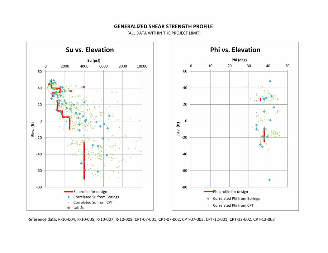
Reference data: R‐10‐004, R‐10‐005, R‐10‐007, R‐10‐009, CPT‐07‐001, CPT‐07‐002, CPT‐07‐003, CPT‐12‐001, CPT‐12‐002, CPT‐12‐003
GENERALIZED SHEAR STRENGTH PROFILE (ALL DATA WITHIN THE PROJECT LIMIT)
‐80
‐60
‐40
‐20
0
20
40
600 2000 4000 6000 8000 10000
Elev. (ft)
Su (psf)
Su vs. Elevation
Su profile for designCorrelated Su from BoringsCorrelated Su from CPTLab Su
‐80
‐60
‐40
‐20
0
20
40
600 10 20 30 40 50
Elev. (ft)
Phi (deg)
Phi vs. Elevation
Phi profile for design
Correlated Phi from Borings
Correlated Phi from CPT
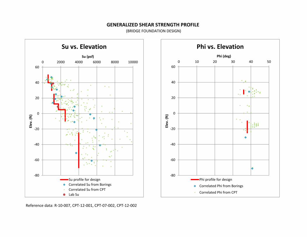
Reference data: R‐10‐007, CPT‐12‐001, CPT‐07‐002, CPT‐12‐002
GENERALIZED SHEAR STRENGTH PROFILE (BRIDGE FOUNDATION DESIGN)
‐80
‐60
‐40
‐20
0
20
40
600 2000 4000 6000 8000 10000
Elev. (ft)
Su (psf)
Su vs. Elevation
Su profile for designCorrelated Su from BoringsCorrelated Su from CPTLab Su
‐80
‐60
‐40
‐20
0
20
40
600 10 20 30 40 50
Elev. (ft)
Phi (deg)
Phi vs. Elevation
Phi profile for design
Correlated Phi from Borings
Correlated Phi from CPT
PILE CAPACITIY
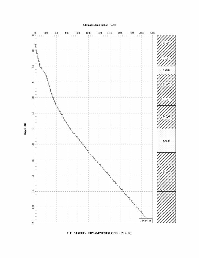
Ultimate Skin Friction (tons)
11TH STREET - PERMANENT STRUCTURE (NO-LIQ)
Dep
th
(ft)
0 200 400 600 800 1000 1200 1400 1600 1800 2000 22000
10
20
30
40
50
60
70
80
90
100
110
120 Dia=8 ft
CLAY
CLAY
SAND
CLAY
CLAY
CLAY
SAND
CLAY
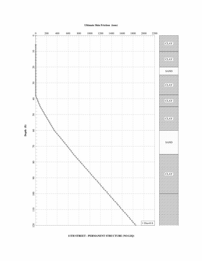
Ultimate Skin Friction (tons)
11TH STREET - PERMANENT STRUCTURE (NO-LIQ)
Dep
th
(ft)
0 200 400 600 800 1000 1200 1400 1600 1800 2000 22000
10
20
30
40
50
60
70
80
90
100
110
120 Dia=8 ft
CLAY
CLAY
SAND
CLAY
CLAY
CLAY
SAND
CLAY
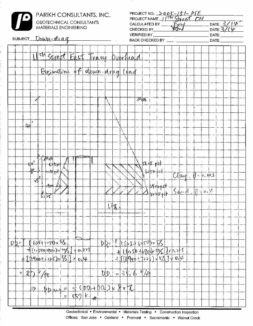
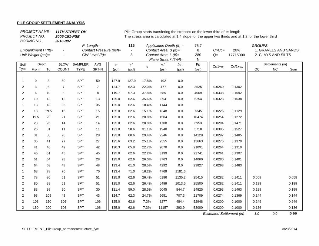
PILE GROUP SETTLEMENT ANALYSIS
PROJECT NAME 11TH STREET OH Pile Group starts transfering the stresses on the lower third of its lengthPROJECT NO. 2005-151-PSE The stress area is calculated at 1:4 slope for the upper two thirds and at 1:2 for the lower thirdBORING NO. R-10-007
P. Length= 115 Application Depth (ft) = 76.7 GROUPSEmbankment H (ft)= - Contact Pressure (psf)= - Contact Area, B (ft)= 8 Cr/Cc= 20% 1. GRAVELS AND SANDS Unit Weight (pcf)= - GW Level (ft)= 3 Contact Area, L (ft)= 280 Q= 17715000 2. CLAYS AND SILTS
Plane Strain? (Y/N)= NBLOW SAMPLER AVG ' v' v' Pp
From To COUNT TYPE SPT-N (pcf) (pcf) (psf) (psf) (psf) OC NC Sum
1 0 3 50 SPT 50 127.9 127.9 17.8% 192 0.0
2 3 6 7 SPT 7 124.7 62.3 22.0% 477 0.0 3525 0.0260 0.1302
2 6 10 8 SPT 8 119.7 57.3 37.8% 685 0.0 4069 0.0338 0.1692
2 10 13 13 SPT 13 125.0 62.6 35.6% 894 0.0 6254 0.0328 0.1638
1 13 18 35 SPT 35 125.0 62.6 10.4% 1144 0.0
2 18 19.5 15 SPT 15 125.0 62.6 15.1% 1348 0.0 7345 0.0226 0.1129
2 19.5 23 21 SPT 21 125.0 62.6 20.8% 1504 0.0 10474 0.0254 0.1272
2 23 26 14 SPT 14 125.0 62.6 28.8% 1708 0.0 6953 0.0294 0.1471
2 26 31 11 SPT 11 121.0 58.6 31.1% 1948 0.0 5718 0.0305 0.1527
2 31 36 28 SPT 28 123.0 60.6 29.4% 2246 0.0 14129 0.0297 0.1485
2 36 41 27 SPT 27 125.6 63.2 25.1% 2555 0.0 13663 0.0276 0.1379
2 41 46 42 SPT 42 128.3 65.9 22.7% 2878 0.0 21091 0.0264 0.1319
2 46 51 45 SPT 45 125.0 62.6 22.2% 3199 0.0 22741 0.0261 0.1307
2 51 64 28 SPT 28 125.0 62.6 26.0% 3763 0.0 14060 0.0280 0.1401
2 64 68 48 SPT 48 123.4 61.0 28.5% 4292 0.0 23827 0.0293 0.1463
1 68 78 70 SPT 70 133.4 71.0 16.2% 4769 1181.6
2 78 80 51 SPT 51 125.0 62.6 26.4% 5186 1135.2 25415 0.0282 0.1411 0.058 0.058
2 80 88 51 SPT 51 125.0 62.6 26.4% 5499 1013.6 25500 0.0282 0.1411 0.199 0.199
2 88 98 30 SPT 30 121.4 59.0 28.5% 6045 844.7 14825 0.0293 0.1463 0.199 0.199
2 98 108 43 SPT 43 124.7 62.3 24.7% 6651 707.3 21709 0.0274 0.1369 0.144 0.144
2 108 150 106 SPT 106 125.0 62.6 7.3% 8277 484.4 52948 0.0200 0.1000 0.249 0.249
2 150 200 106 SPT 106 125.0 62.6 7.3% 11157 293.9 53000 0.0200 0.1000 0.136 0.136
Estimated Settlement (in)= 1.0 0.0 0.99
SoilType
Depth
Settlements (in)Cr/1+e0 Cc/1+e0
SETTLEMENT_PileGroup_permanentstructure_fyw 3/23/2014
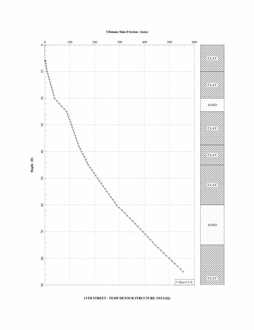
Ultimate Skin Friction (tons)
11TH STREET - TEMP DETOUR STRUCTURE (NO-LIQ)
Dep
th
(ft)
0 100 200 300 400 500 6000
10
20
30
40
50
60
70
80
90
Dia=3.5 ft
CLAY
CLAY
SAND
CLAY
CLAY
CLAY
SAND
CLAY
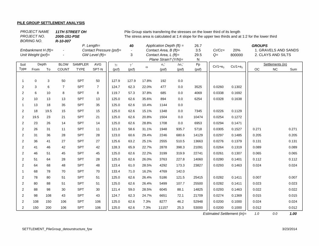
PILE GROUP SETTLEMENT ANALYSIS
PROJECT NAME 11TH STREET OH Pile Group starts transfering the stresses on the lower third of its lengthPROJECT NO. 2005-151-PSE The stress area is calculated at 1:4 slope for the upper two thirds and at 1:2 for the lower thirdBORING NO. R-10-007
P. Length= 40 Application Depth (ft) = 26.7 GROUPSEmbankment H (ft)= - Contact Pressure (psf)= - Contact Area, B (ft)= 3.5 Cr/Cc= 20% 1. GRAVELS AND SANDS Unit Weight (pcf)= - GW Level (ft)= 3 Contact Area, L (ft)= 29.5 Q= 800000 2. CLAYS AND SILTS
Plane Strain? (Y/N)= NBLOW SAMPLER AVG ' v' v' Pp
From To COUNT TYPE SPT-N (pcf) (pcf) (psf) (psf) (psf) OC NC Sum
1 0 3 50 SPT 50 127.9 127.9 17.8% 192 0.0
2 3 6 7 SPT 7 124.7 62.3 22.0% 477 0.0 3525 0.0260 0.1302
2 6 10 8 SPT 8 119.7 57.3 37.8% 685 0.0 4069 0.0338 0.1692
2 10 13 13 SPT 13 125.0 62.6 35.6% 894 0.0 6254 0.0328 0.1638
1 13 18 35 SPT 35 125.0 62.6 10.4% 1144 0.0
2 18 19.5 15 SPT 15 125.0 62.6 15.1% 1348 0.0 7345 0.0226 0.1129
2 19.5 23 21 SPT 21 125.0 62.6 20.8% 1504 0.0 10474 0.0254 0.1272
2 23 26 14 SPT 14 125.0 62.6 28.8% 1708 0.0 6953 0.0294 0.1471
2 26 31 11 SPT 11 121.0 58.6 31.1% 1948 935.7 5718 0.0305 0.1527 0.271 0.271
2 31 36 28 SPT 28 123.0 60.6 29.4% 2246 680.6 14129 0.0297 0.1485 0.205 0.205
2 36 41 27 SPT 27 125.6 63.2 25.1% 2555 510.5 13663 0.0276 0.1379 0.131 0.131
2 41 46 42 SPT 42 128.3 65.9 22.7% 2878 398.3 21091 0.0264 0.1319 0.089 0.089
2 46 51 45 SPT 45 125.0 62.6 22.2% 3199 319.9 22741 0.0261 0.1307 0.065 0.065
2 51 64 28 SPT 28 125.0 62.6 26.0% 3763 227.8 14060 0.0280 0.1401 0.112 0.112
2 64 68 48 SPT 48 123.4 61.0 28.5% 4292 173.3 23827 0.0293 0.1463 0.024 0.024
1 68 78 70 SPT 70 133.4 71.0 16.2% 4769 142.0
2 78 80 51 SPT 51 125.0 62.6 26.4% 5186 121.5 25415 0.0282 0.1411 0.007 0.007
2 80 88 51 SPT 51 125.0 62.6 26.4% 5499 107.7 25500 0.0282 0.1411 0.023 0.023
2 88 98 30 SPT 30 121.4 59.0 28.5% 6045 88.1 14825 0.0293 0.1463 0.022 0.022
2 98 108 43 SPT 43 124.7 62.3 24.7% 6651 72.1 21709 0.0274 0.1369 0.015 0.015
2 108 150 106 SPT 106 125.0 62.6 7.3% 8277 46.2 52948 0.0200 0.1000 0.024 0.024
2 150 200 106 SPT 106 125.0 62.6 7.3% 11157 25.3 53000 0.0200 0.1000 0.012 0.012
Estimated Settlement (in)= 1.0 0.0 1.00
SoilType
Depth
Settlements (in)Cr/1+e0 Cc/1+e0
SETTLEMENT_PileGroup_detourstructure_fyw 3/23/2014
LATERAL SPREADING ANALYSIS
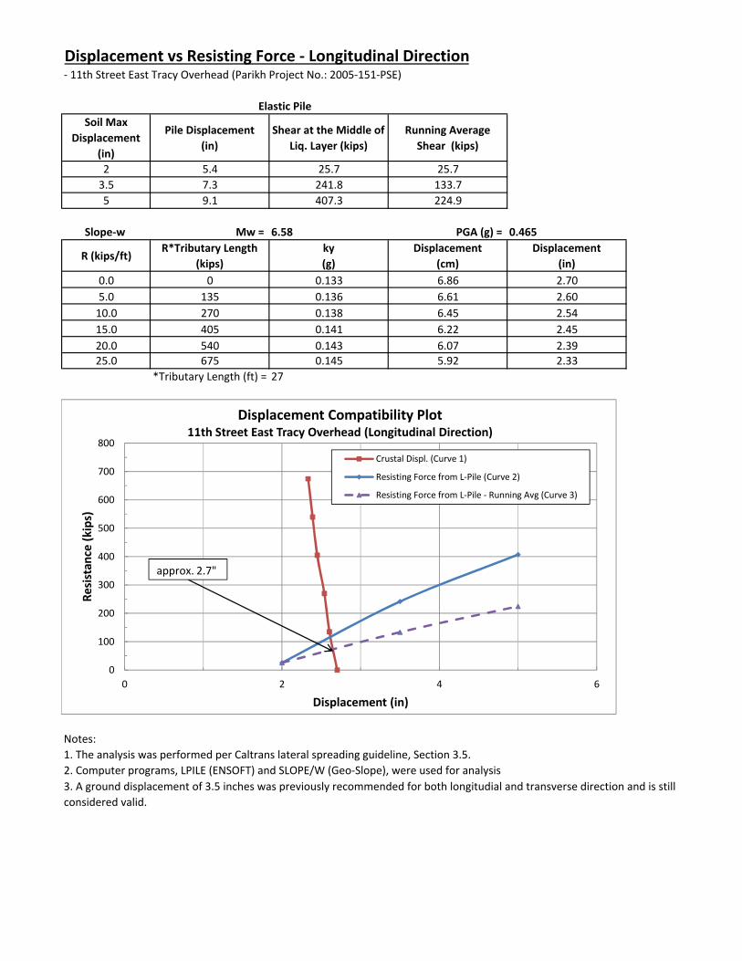
Displacement vs Resisting Force ‐ Longitudinal Direction‐ 11th Street East Tracy Overhead (Parikh Project No.: 2005‐151‐PSE)
Soil Max Displacement
(in)
Pile Displacement (in)
Shear at the Middle of Liq. Layer (kips)
Running Average Shear (kips)
2 5.4 25.7 25.73.5 7.3 241.8 133.75 9.1 407.3 224.9
Slope‐w Mw = 6.58 PGA (g) = 0.465
R (kips/ft)R*Tributary Length
(kips)ky (g)
Displacement (cm)
Displacement (in)
0.0 0 0.133 6.86 2.705.0 135 0.136 6.61 2.6010.0 270 0.138 6.45 2.5415.0 405 0.141 6.22 2.4520.0 540 0.143 6.07 2.3925.0 675 0.145 5.92 2.33
*Tributary Length (ft) = 27
Notes:1. The analysis was performed per Caltrans lateral spreading guideline, Section 3.5.2. Computer programs, LPILE (ENSOFT) and SLOPE/W (Geo‐Slope), were used for analysis
Elastic Pile
3. A ground displacement of 3.5 inches was previously recommended for both longitudial and transverse direction and is still considered valid.
0
100
200
300
400
500
600
700
800
0 2 4 6
Resistan
ce (k
ips)
Displacement (in)
Displacement Compatibility Plot11th Street East Tracy Overhead (Longitudinal Direction)
Crustal Displ. (Curve 1)
Resisting Force from L‐Pile (Curve 2)
Resisting Force from L‐Pile ‐ Running Avg (Curve 3)
approx. 2.7"
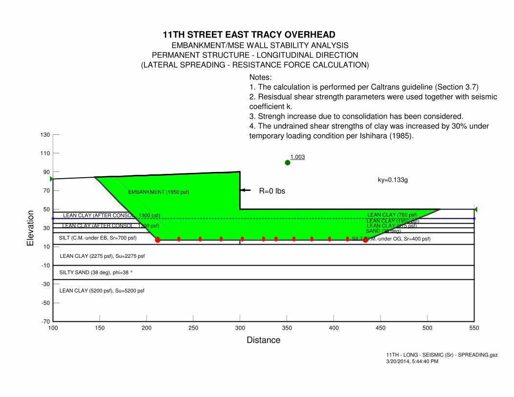
1.003
11TH STREET EAST TRACY OVERHEAD
EMBANKMENT/MSE WALL STABILITY ANALYSIS
PERMANENT STRUCTURE - LONGITUDINAL DIRECTION
(LATERAL SPREADING - RESISTANCE FORCE CALCULATION)
LEAN CLAY (AFTER CONSOL., 1300 psf)
SILT (C.M.-under EB, Sr=700 psf)
LEAN CLAY (780 psf)
EMBANKMENT (1950 psf)
LEAN CLAY (AFTER CONSOL., 1300 psf)
LEAN CLAY (975 psf)SAND (36 deg)
LEAN CLAY (2275 psf), Su=2275 psf
SILT (C.M.-under OG, Sr=400 psf)
SILTY SAND (38 deg), phi=38 °
11TH - LONG - SEISMIC (Sr) - SPREADING.gsz
3/20/2014, 5:44:40 PM
ky=0.133g
LEAN CLAY (5200 psf), Su=5200 psf
LEAN CLAY (1950 psf)
Notes:
1. The calculation is performed per Caltrans guideline (Section 3.7)
2. Resisdual shear strength parameters were used together with seismic
coefficient k.
3. Strengh increase due to consolidation has been considered.
4. The undrained shear strengths of clay was increased by 30% under
temporary loading condition per Ishihara (1985).
R=0 lbs
Distance
100 150 200 250 300 350 400 450 500 550
Ele
va
tio
n
-70
-50
-30
-10
10
30
50
70
90
110
130

1.001
11TH STREET EAST TRACY OVERHEAD
EMBANKMENT/MSE WALL STABILITY ANALYSIS
PERMANENT STRUCTURE - LONGITUDINAL DIRECTION
(LATERAL SPREADING - RESISTANCE FORCE CALCULATION)
LEAN CLAY (AFTER CONSOL., 1300 psf)
SILT (C.M.-under EB, Sr=700 psf)
LEAN CLAY (780 psf)
EMBANKMENT (1950 psf)
LEAN CLAY (AFTER CONSOL., 1300 psf)
LEAN CLAY (975 psf)SAND (36 deg)
LEAN CLAY (2275 psf), Su=2275 psf
SILT (C.M.-under OG, Sr=400 psf)
SILTY SAND (38 deg), phi=38 °
11TH - LONG - SEISMIC (Sr) - SPREADING.gsz
3/20/2014, 6:02:53 PM
ky=0.136g
LEAN CLAY (5200 psf), Su=5200 psf
LEAN CLAY (1950 psf)
Notes:
1. The calculation is performed per Caltrans guideline (Section 3.7)
2. Resisdual shear strength parameters were used together with seismic
coefficient k.
3. Strengh increase due to consolidation has been considered.
4. The undrained shear strengths of clay was increased by 30% under
temporary loading condition per Ishihara (1985).
R=5000 lbs
Distance
100 150 200 250 300 350 400 450 500 550
Ele
va
tio
n
-70
-50
-30
-10
10
30
50
70
90
110
130

1.003
11TH STREET EAST TRACY OVERHEAD
EMBANKMENT/MSE WALL STABILITY ANALYSIS
PERMANENT STRUCTURE - LONGITUDINAL DIRECTION
(LATERAL SPREADING - RESISTANCE FORCE CALCULATION)
LEAN CLAY (AFTER CONSOL., 1300 psf)
SILT (C.M.-under EB, Sr=700 psf)
LEAN CLAY (780 psf)
EMBANKMENT (1950 psf)
LEAN CLAY (AFTER CONSOL., 1300 psf)
LEAN CLAY (975 psf)SAND (36 deg)
LEAN CLAY (2275 psf), Su=2275 psf
SILT (C.M.-under OG, Sr=400 psf)
SILTY SAND (38 deg), phi=38 °
11TH - LONG - SEISMIC (Sr) - SPREADING.gsz
3/20/2014, 6:01:26 PM
ky=0.138g
LEAN CLAY (5200 psf), Su=5200 psf
LEAN CLAY (1950 psf)
Notes:
1. The calculation is performed per Caltrans guideline (Section 3.7)
2. Resisdual shear strength parameters were used together with seismic
coefficient k.
3. Strengh increase due to consolidation has been considered.
4. The undrained shear strengths of clay was increased by 30% under
temporary loading condition per Ishihara (1985).
R=10000 lbs
Distance
100 150 200 250 300 350 400 450 500 550
Ele
va
tio
n
-70
-50
-30
-10
10
30
50
70
90
110
130

1.000
11TH STREET EAST TRACY OVERHEAD
EMBANKMENT/MSE WALL STABILITY ANALYSIS
PERMANENT STRUCTURE - LONGITUDINAL DIRECTION
(LATERAL SPREADING - RESISTANCE FORCE CALCULATION)
LEAN CLAY (AFTER CONSOL., 1300 psf)
SILT (C.M.-under EB, Sr=700 psf)
LEAN CLAY (780 psf)
EMBANKMENT (1950 psf)
LEAN CLAY (AFTER CONSOL., 1300 psf)
LEAN CLAY (975 psf)SAND (36 deg)
LEAN CLAY (2275 psf), Su=2275 psf
SILT (C.M.-under OG, Sr=400 psf)
SILTY SAND (38 deg), phi=38 °
11TH - LONG - SEISMIC (Sr) - SPREADING.gsz
3/20/2014, 5:59:46 PM
ky=0.141g
LEAN CLAY (5200 psf), Su=5200 psf
LEAN CLAY (1950 psf)
Notes:
1. The calculation is performed per Caltrans guideline (Section 3.7)
2. Resisdual shear strength parameters were used together with seismic
coefficient k.
3. Strengh increase due to consolidation has been considered.
4. The undrained shear strengths of clay was increased by 30% under
temporary loading condition per Ishihara (1985).
R=15000 lbs
Distance
100 150 200 250 300 350 400 450 500 550
Ele
va
tio
n
-70
-50
-30
-10
10
30
50
70
90
110
130
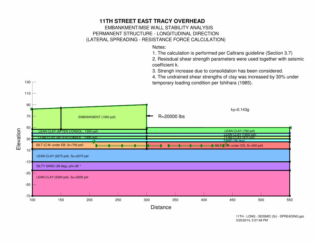
11TH STREET EAST TRACY OVERHEAD
EMBANKMENT/MSE WALL STABILITY ANALYSIS
PERMANENT STRUCTURE - LONGITUDINAL DIRECTION
(LATERAL SPREADING - RESISTANCE FORCE CALCULATION)
LEAN CLAY (AFTER CONSOL., 1300 psf)
SILT (C.M.-under EB, Sr=700 psf)
LEAN CLAY (780 psf)
EMBANKMENT (1950 psf)
LEAN CLAY (AFTER CONSOL., 1300 psf)
LEAN CLAY (975 psf)SAND (36 deg)
LEAN CLAY (2275 psf), Su=2275 psf
SILT (C.M.-under OG, Sr=400 psf)
SILTY SAND (38 deg), phi=38 °
11TH - LONG - SEISMIC (Sr) - SPREADING.gsz
3/20/2014, 5:57:48 PM
ky=0.143g
LEAN CLAY (5200 psf), Su=5200 psf
LEAN CLAY (1950 psf)
Notes:
1. The calculation is performed per Caltrans guideline (Section 3.7)
2. Resisdual shear strength parameters were used together with seismic
coefficient k.
3. Strengh increase due to consolidation has been considered.
4. The undrained shear strengths of clay was increased by 30% under
temporary loading condition per Ishihara (1985).
R=20000 lbs
Distance
100 150 200 250 300 350 400 450 500 550
Ele
va
tio
n
-70
-50
-30
-10
10
30
50
70
90
110
130

1.003
11TH STREET EAST TRACY OVERHEAD
EMBANKMENT/MSE WALL STABILITY ANALYSIS
PERMANENT STRUCTURE - LONGITUDINAL DIRECTION
(LATERAL SPREADING - RESISTANCE FORCE CALCULATION)
LEAN CLAY (AFTER CONSOL., 1300 psf)
SILT (C.M.-under EB, Sr=700 psf)
LEAN CLAY (780 psf)
EMBANKMENT (1950 psf)
LEAN CLAY (AFTER CONSOL., 1300 psf)
LEAN CLAY (975 psf)SAND (36 deg)
LEAN CLAY (2275 psf), Su=2275 psf
SILT (C.M.-under OG, Sr=400 psf)
SILTY SAND (38 deg), phi=38 °
11TH - LONG - SEISMIC (Sr) - SPREADING.gsz
3/20/2014, 5:54:05 PM
ky=0.145g
LEAN CLAY (5200 psf), Su=5200 psf
LEAN CLAY (1950 psf)
Notes:
1. The calculation is performed per Caltrans guideline (Section 3.7)
2. Resisdual shear strength parameters were used together with seismic
coefficient k.
3. Strengh increase due to consolidation has been considered.
4. The undrained shear strengths of clay was increased by 30% under
temporary loading condition per Ishihara (1985).
R=25000 lbs
Distance
100 150 200 250 300 350 400 450 500 550
Ele
va
tio
n
-70
-50
-30
-10
10
30
50
70
90
110
130
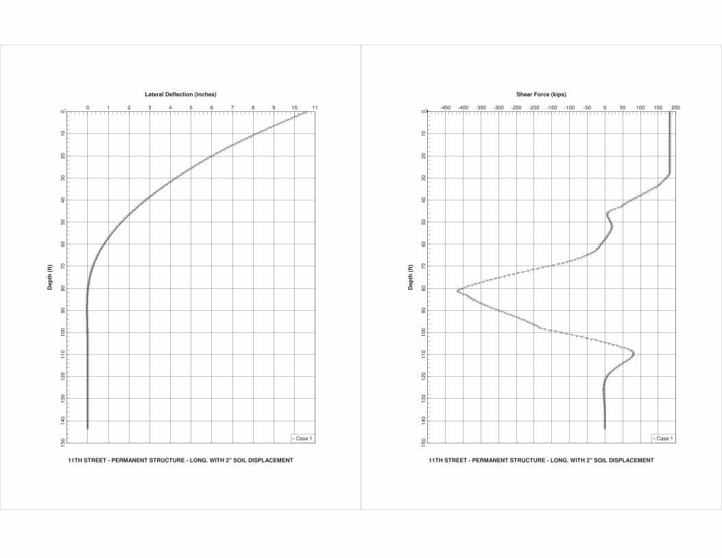
Lateral Deflection (inches)
11TH STREET - PERMANENT STRUCTURE - LONG. WITH 2" SOIL DISPLACEMENT
Dep
th (
ft)
�� 0 1 2 3 4 5 6 7 8 9 10 11
010
2030
4050
6070
8090
100
110
120
130
140
150 Case 1
Shear Force (kips)
11TH STREET - PERMANENT STRUCTURE - LONG. WITH 2" SOIL DISPLACEMENT
Dep
th (
ft)
���� -450 -400 -350 -300 -250 -200 -150 -100 -50 0 50 100 150 200
010
2030
4050
6070
8090
100
110
120
130
140
150 Case 1
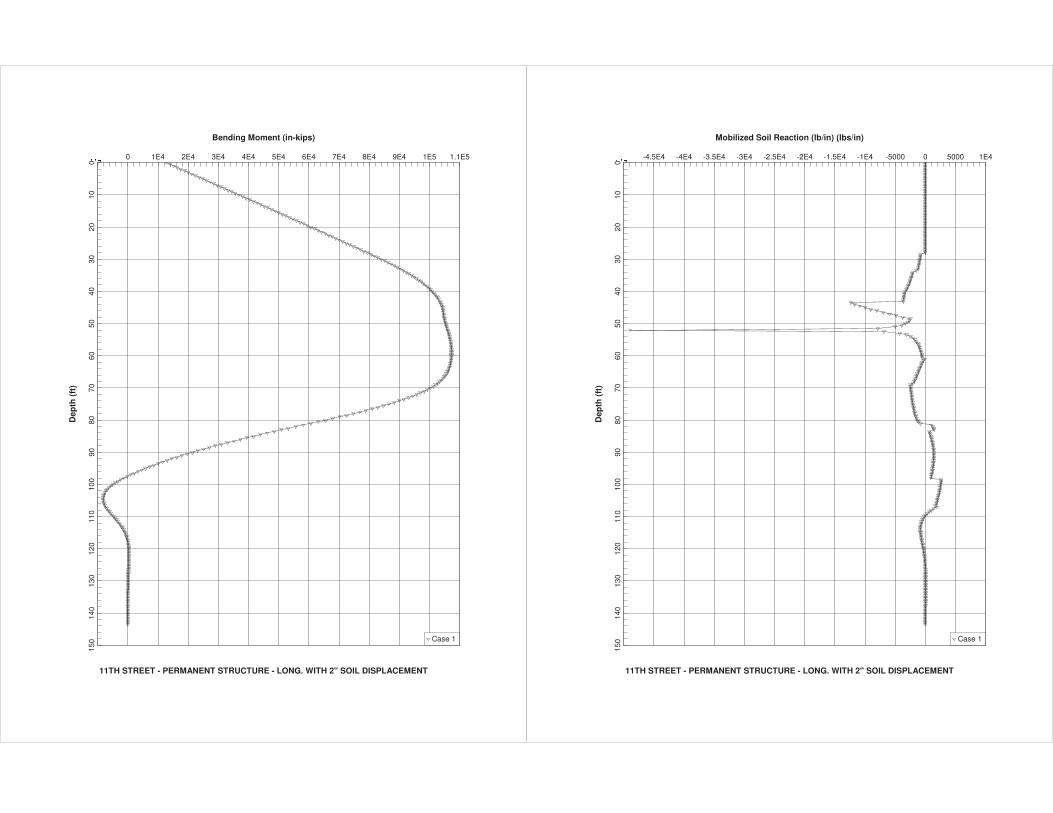
Bending Moment (in-kips)
11TH STREET - PERMANENT STRUCTURE - LONG. WITH 2" SOIL DISPLACEMENT
Dep
th (
ft)
���� 0 1E4 2E4 3E4 4E4 5E4 6E4 7E4 8E4 9E4 1E5 1.1E5
010
2030
4050
6070
8090
100
110
120
130
140
150 Case 1
Mobilized Soil Reaction (lb/in) (lbs/in)
11TH STREET - PERMANENT STRUCTURE - LONG. WITH 2" SOIL DISPLACEMENT
Dep
th (
ft)
���� -4.5E4 -4E4 -3.5E4 -3E4 -2.5E4 -2E4 -1.5E4 -1E4 -5000 0 5000 1E4
010
2030
4050
6070
8090
100
110
120
130
140
150 Case 1

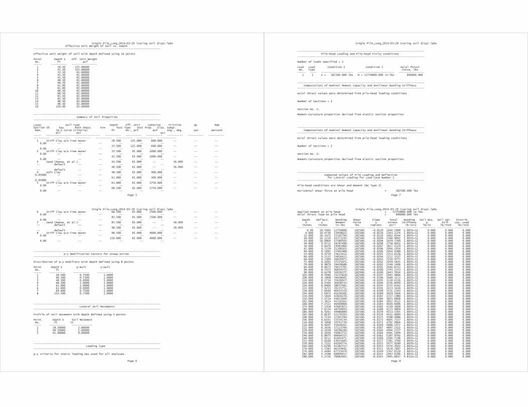
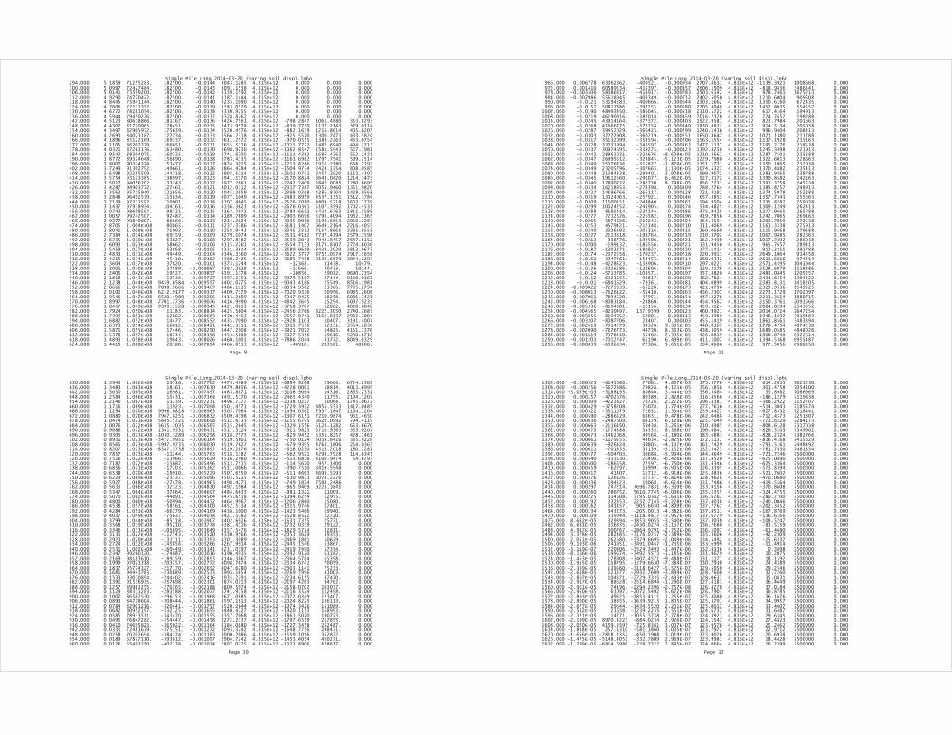

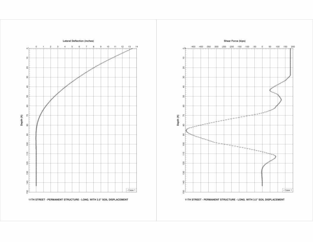
Lateral Deflection (inches)
11TH STREET - PERMANENT STRUCTURE - LONG. WITH 3.5" SOIL DISPLACEMENT
Dep
th (
ft)
�� 0 1 2 3 4 5 6 7 8 9 10 11 12 13 14
010
2030
4050
6070
8090
100
110
120
130
140
150 Case 1
Shear Force (kips)
11TH STREET - PERMANENT STRUCTURE - LONG. WITH 3.5" SOIL DISPLACEMENT
Dep
th (
ft)
���� -450 -400 -350 -300 -250 -200 -150 -100 -50 0 50 100 150 200
010
2030
4050
6070
8090
100
110
120
130
140
150 Case 1
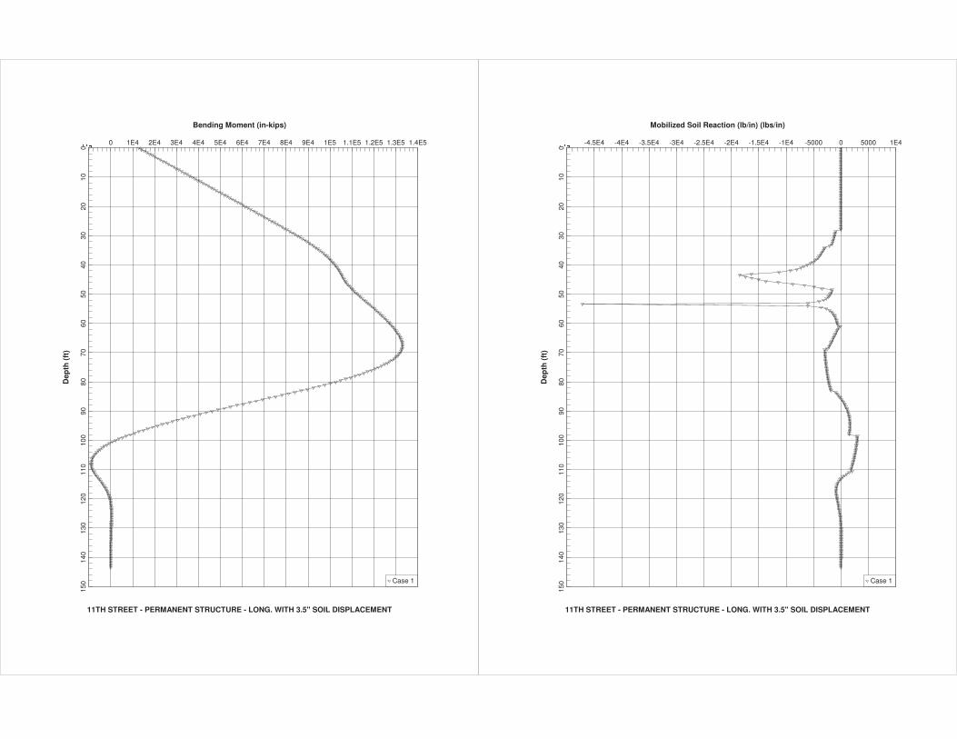
Bending Moment (in-kips)
11TH STREET - PERMANENT STRUCTURE - LONG. WITH 3.5" SOIL DISPLACEMENT
Dep
th (
ft)
���� 0 1E4 2E4 3E4 4E4 5E4 6E4 7E4 8E4 9E4 1E5 1.1E5 1.2E5 1.3E5 1.4E5
010
2030
4050
6070
8090
100
110
120
130
140
150 Case 1
Mobilized Soil Reaction (lb/in) (lbs/in)
11TH STREET - PERMANENT STRUCTURE - LONG. WITH 3.5" SOIL DISPLACEMENT
Dep
th (
ft)
���� -4.5E4 -4E4 -3.5E4 -3E4 -2.5E4 -2E4 -1.5E4 -1E4 -5000 0 5000 1E4
010
2030
4050
6070
8090
100
110
120
130
140
150 Case 1


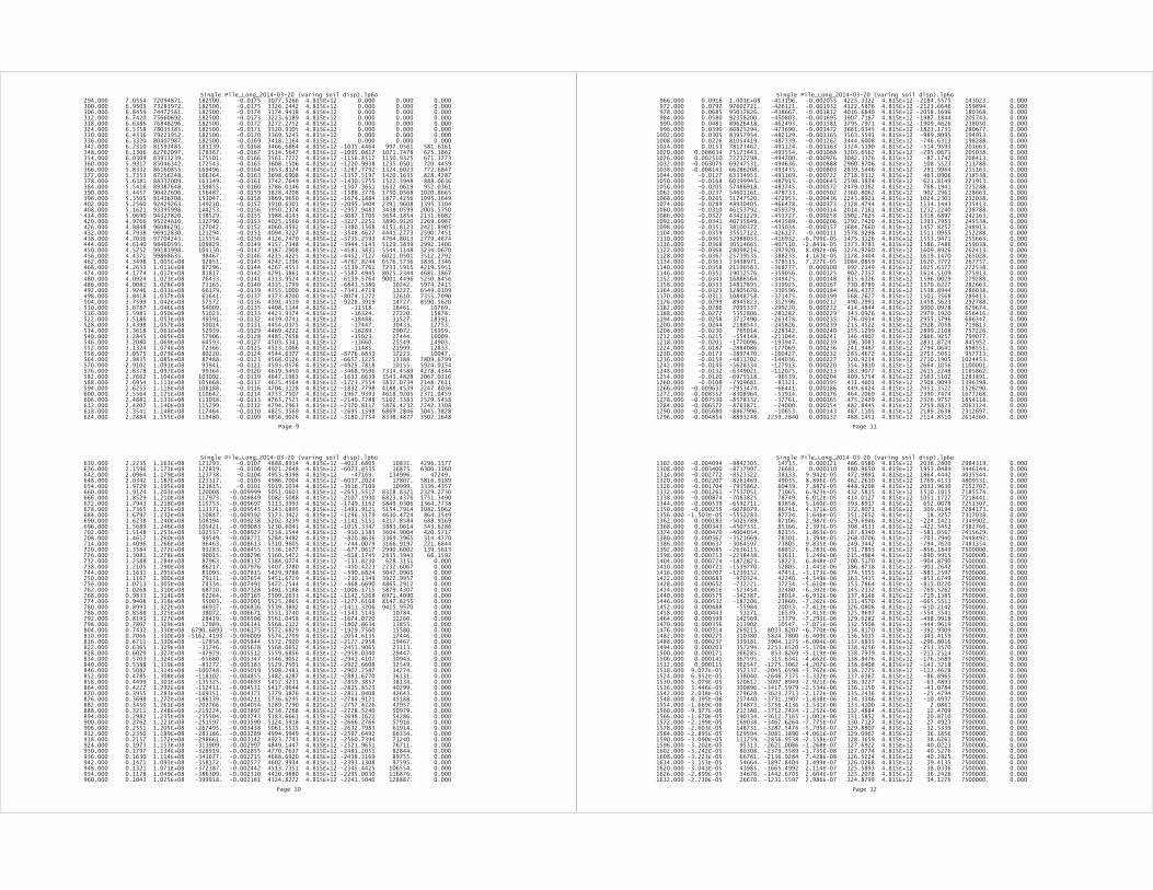

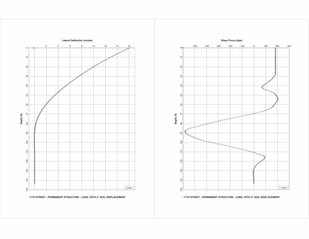
Lateral Deflection (inches)
11TH STREET - PERMANENT STRUCTURE - LONG. WITH 5" SOIL DISPLACEMENT
Dep
th (
ft)
� 2 4 6 8 10 12 14 16
010
2030
4050
6070
8090
100
110
120
130
140
150 Case 1
Shear Force (kips)
11TH STREET - PERMANENT STRUCTURE - LONG. WITH 5" SOIL DISPLACEMENT
Dep
th (
ft)
���� -500 -400 -300 -200 -100 0 100 200 300
010
2030
4050
6070
8090
100
110
120
130
140
150 Case 1
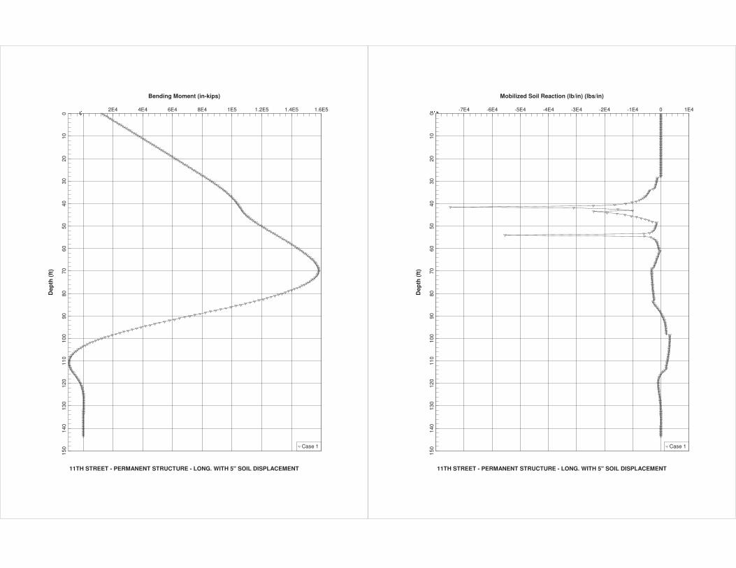
Bending Moment (in-kips)
11TH STREET - PERMANENT STRUCTURE - LONG. WITH 5" SOIL DISPLACEMENT
Dep
th (
ft)
� 2E4 4E4 6E4 8E4 1E5 1.2E5 1.4E5 1.6E5
010
2030
4050
6070
8090
100
110
120
130
140
150 Case 1
Mobilized Soil Reaction (lb/in) (lbs/in)
11TH STREET - PERMANENT STRUCTURE - LONG. WITH 5" SOIL DISPLACEMENT
Dep
th (
ft)
���� -7E4 -6E4 -5E4 -4E4 -3E4 -2E4 -1E4 0 1E4
010
2030
4050
6070
8090
100
110
120
130
140
150 Case 1


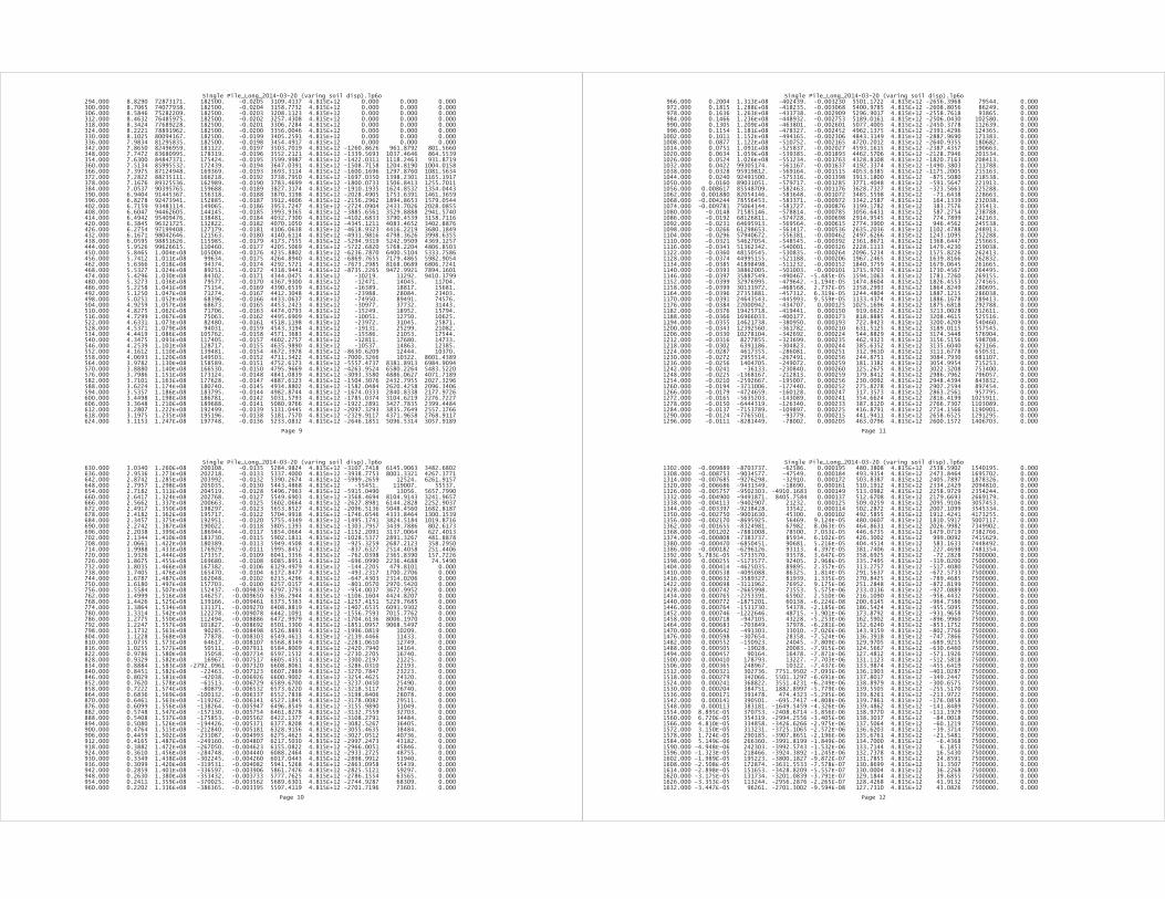
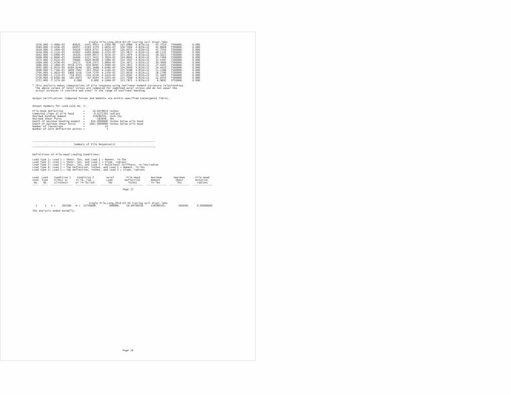
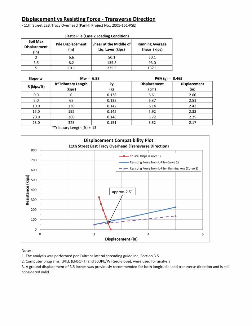
Displacement vs Resisting Force ‐ Transverse Direction‐ 11th Street East Tracy Overhead (Parikh Project No.: 2005‐151‐PSE)
Soil Max Displacement
(in)
Pile Displacement (in)
Shear at the Middle of Liq. Layer (kips)
Running Average Shear (kips)
2 6.6 50.1 50.13.5 8.2 135.8 93.05 10.1 225.5 137.1
Slope‐w Mw = 6.58 PGA (g) = 0.465
R (kips/ft)R*Tributary Length
(kips)ky (g)
Displacement (cm)
Displacement (in)
0.0 0 0.136 6.61 2.605.0 65 0.139 6.37 2.5110.0 130 0.142 6.14 2.4215.0 195 0.145 5.92 2.3320.0 260 0.148 5.72 2.2525.0 325 0.151 5.52 2.17
*Tributary Length (ft) = 13
Notes:1. The analysis was performed per Caltrans lateral spreading guideline, Section 3.5.2. Computer programs, LPILE (ENSOFT) and SLOPE/W (Geo‐Slope), were used for analysis
Elastic Pile (Case 2 Loading Condition)
3. A ground displacement of 3.5 inches was previously recommended for both longitudial and transverse direction and is still considered valid.
0
100
200
300
400
500
600
700
800
0 2 4 6
Resistan
ce (k
ips)
Displacement (in)
Displacement Compatibility Plot11th Street East Tracy Overhead (Transverse Direction)
Crustal Displ. (Curve 1)
Resisting Force from L‐Pile (Curve 2)
Resisting Force from L‐Pile ‐ Running Avg (Curve 3)
approx. 2.5"
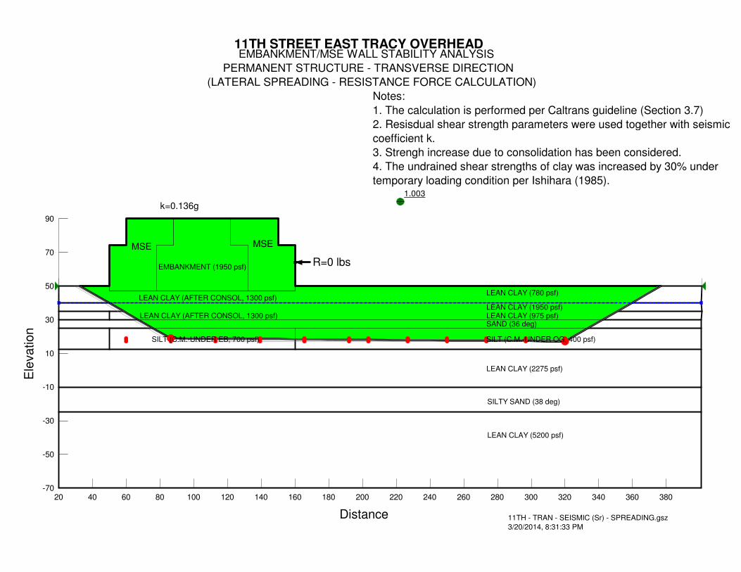
1.003
11TH STREET EAST TRACY OVERHEAD EMBANKMENT/MSE WALL STABILITY ANALYSIS
PERMANENT STRUCTURE - TRANSVERSE DIRECTION
(LATERAL SPREADING - RESISTANCE FORCE CALCULATION)
MSE MSE
EMBANKMENT (1950 psf)
LEAN CLAY (780 psf)
LEAN CLAY (1950 psf)
SAND (36 deg)
LEAN CLAY (2275 psf)
SILT (C.M.-UNDER OG, 400 psf)
SILTY SAND (38 deg)
11TH - TRAN - SEISMIC (Sr) - SPREADING.gsz
3/20/2014, 8:31:33 PM
k=0.136g
LEAN CLAY (5200 psf)
LEAN CLAY (AFTER CONSOL, 1300 psf)
Notes:
1. The calculation is performed per Caltrans guideline (Section 3.7)
2. Resisdual shear strength parameters were used together with seismic
coefficient k.
3. Strengh increase due to consolidation has been considered.
4. The undrained shear strengths of clay was increased by 30% under
temporary loading condition per Ishihara (1985).
LEAN CLAY (975 psf)
SILT (C.M.-UNDER EB, 700 psf)
LEAN CLAY (AFTER CONSOL, 1300 psf)
R=0 lbs
Distance
20 40 60 80 100 120 140 160 180 200 220 240 260 280 300 320 340 360 380
Ele
va
tio
n
-70
-50
-30
-10
10
30
50
70
90

1.003
11TH STREET EAST TRACY OVERHEAD EMBANKMENT/MSE WALL STABILITY ANALYSIS
PERMANENT STRUCTURE - TRANSVERSE DIRECTION
(LATERAL SPREADING - RESISTANCE FORCE CALCULATION)
MSE MSE
EMBANKMENT (1950 psf)
LEAN CLAY (780 psf)
LEAN CLAY (1950 psf)
SAND (36 deg)
LEAN CLAY (2275 psf)
SILT (C.M.-UNDER OG, 400 psf)
SILTY SAND (38 deg)
11TH - TRAN - SEISMIC (Sr) - SPREADING.gsz
3/20/2014, 8:40:05 PM
k=0.139g
LEAN CLAY (5200 psf)
LEAN CLAY (AFTER CONSOL, 1300 psf)
Notes:
1. The calculation is performed per Caltrans guideline (Section 3.7)
2. Resisdual shear strength parameters were used together with seismic
coefficient k.
3. Strengh increase due to consolidation has been considered.
4. The undrained shear strengths of clay was increased by 30% under
temporary loading condition per Ishihara (1985).
LEAN CLAY (975 psf)
SILT (C.M.-UNDER EB, 700 psf)
LEAN CLAY (AFTER CONSOL, 1300 psf)
R=5000 lbs
Distance
20 40 60 80 100 120 140 160 180 200 220 240 260 280 300 320 340 360 380
Ele
va
tio
n
-70
-50
-30
-10
10
30
50
70
90

1.002
11TH STREET EAST TRACY OVERHEAD EMBANKMENT/MSE WALL STABILITY ANALYSIS
PERMANENT STRUCTURE - TRANSVERSE DIRECTION
(LATERAL SPREADING - RESISTANCE FORCE CALCULATION)
MSE MSE
EMBANKMENT (1950 psf)
LEAN CLAY (780 psf)
LEAN CLAY (1950 psf)
SAND (36 deg)
LEAN CLAY (2275 psf)
SILT (C.M.-UNDER OG, 400 psf)
SILTY SAND (38 deg)
11TH - TRAN - SEISMIC (Sr) - SPREADING.gsz
3/20/2014, 8:39:15 PM
k=0.142g
LEAN CLAY (5200 psf)
LEAN CLAY (AFTER CONSOL, 1300 psf)
Notes:
1. The calculation is performed per Caltrans guideline (Section 3.7)
2. Resisdual shear strength parameters were used together with seismic
coefficient k.
3. Strengh increase due to consolidation has been considered.
4. The undrained shear strengths of clay was increased by 30% under
temporary loading condition per Ishihara (1985).
LEAN CLAY (975 psf)
SILT (C.M.-UNDER EB, 700 psf)
LEAN CLAY (AFTER CONSOL, 1300 psf)
R=10000 lbs
Distance
20 40 60 80 100 120 140 160 180 200 220 240 260 280 300 320 340 360 380
Ele
va
tio
n
-70
-50
-30
-10
10
30
50
70
90

1.001
11TH STREET EAST TRACY OVERHEAD EMBANKMENT/MSE WALL STABILITY ANALYSIS
PERMANENT STRUCTURE - TRANSVERSE DIRECTION
(LATERAL SPREADING - RESISTANCE FORCE CALCULATION)
MSE MSE
EMBANKMENT (1950 psf)
LEAN CLAY (780 psf)
LEAN CLAY (1950 psf)
SAND (36 deg)
LEAN CLAY (2275 psf)
SILT (C.M.-UNDER OG, 400 psf)
SILTY SAND (38 deg)
11TH - TRAN - SEISMIC (Sr) - SPREADING.gsz
3/20/2014, 8:38:32 PM
k=0.145g
LEAN CLAY (5200 psf)
LEAN CLAY (AFTER CONSOL, 1300 psf)
Notes:
1. The calculation is performed per Caltrans guideline (Section 3.7)
2. Resisdual shear strength parameters were used together with seismic
coefficient k.
3. Strengh increase due to consolidation has been considered.
4. The undrained shear strengths of clay was increased by 30% under
temporary loading condition per Ishihara (1985).
LEAN CLAY (975 psf)
SILT (C.M.-UNDER EB, 700 psf)
LEAN CLAY (AFTER CONSOL, 1300 psf)
R=15000 lbs
Distance
20 40 60 80 100 120 140 160 180 200 220 240 260 280 300 320 340 360 380
Ele
va
tio
n
-70
-50
-30
-10
10
30
50
70
90
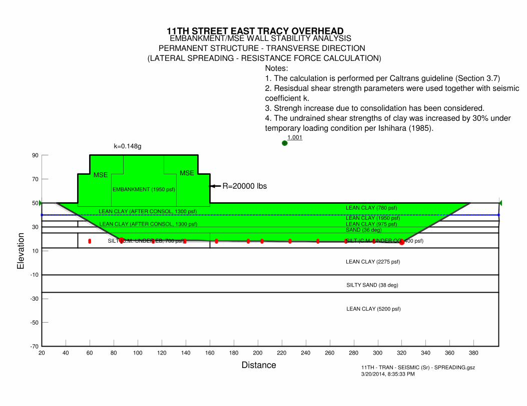
1.001
11TH STREET EAST TRACY OVERHEAD EMBANKMENT/MSE WALL STABILITY ANALYSIS
PERMANENT STRUCTURE - TRANSVERSE DIRECTION
(LATERAL SPREADING - RESISTANCE FORCE CALCULATION)
MSE MSE
EMBANKMENT (1950 psf)
LEAN CLAY (780 psf)
LEAN CLAY (1950 psf)
SAND (36 deg)
LEAN CLAY (2275 psf)
SILT (C.M.-UNDER OG, 400 psf)
SILTY SAND (38 deg)
11TH - TRAN - SEISMIC (Sr) - SPREADING.gsz
3/20/2014, 8:35:33 PM
k=0.148g
LEAN CLAY (5200 psf)
LEAN CLAY (AFTER CONSOL, 1300 psf)
Notes:
1. The calculation is performed per Caltrans guideline (Section 3.7)
2. Resisdual shear strength parameters were used together with seismic
coefficient k.
3. Strengh increase due to consolidation has been considered.
4. The undrained shear strengths of clay was increased by 30% under
temporary loading condition per Ishihara (1985).
LEAN CLAY (975 psf)
SILT (C.M.-UNDER EB, 700 psf)
LEAN CLAY (AFTER CONSOL, 1300 psf)
R=20000 lbs
Distance
20 40 60 80 100 120 140 160 180 200 220 240 260 280 300 320 340 360 380
Ele
va
tio
n
-70
-50
-30
-10
10
30
50
70
90

1.000
11TH STREET EAST TRACY OVERHEAD EMBANKMENT/MSE WALL STABILITY ANALYSIS
PERMANENT STRUCTURE - TRANSVERSE DIRECTION
(LATERAL SPREADING - RESISTANCE FORCE CALCULATION)
MSE MSE
EMBANKMENT (1950 psf)
LEAN CLAY (780 psf)
LEAN CLAY (1950 psf)
SAND (36 deg)
LEAN CLAY (2275 psf)
SILT (C.M.-UNDER OG, 400 psf)
SILTY SAND (38 deg)
11TH - TRAN - SEISMIC (Sr) - SPREADING.gsz
3/20/2014, 8:34:02 PM
k=0.151g
LEAN CLAY (5200 psf)
LEAN CLAY (AFTER CONSOL, 1300 psf)
Notes:
1. The calculation is performed per Caltrans guideline (Section 3.7)
2. Resisdual shear strength parameters were used together with seismic
coefficient k.
3. Strengh increase due to consolidation has been considered.
4. The undrained shear strengths of clay was increased by 30% under
temporary loading condition per Ishihara (1985).
LEAN CLAY (975 psf)
SILT (C.M.-UNDER EB, 700 psf)
LEAN CLAY (AFTER CONSOL, 1300 psf)
R=25000 lbs
Distance
20 40 60 80 100 120 140 160 180 200 220 240 260 280 300 320 340 360 380
Ele
va
tio
n
-70
-50
-30
-10
10
30
50
70
90
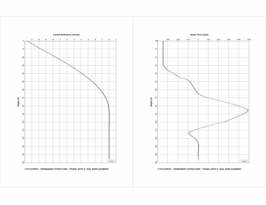
Lateral Deflection (inches)
11TH STREET - PERMANENT STRUCTURE - TRANS. WITH 2" SOIL DISPLACEMENT
Dep
th (
ft)
��� -11 -10 -9 -8 -7 -6 -5 -4 -3 -2 -1 0 1
010
2030
4050
6070
8090
100
110
120
130
140
150 Case 1
Shear Force (kips)
11TH STREET - PERMANENT STRUCTURE - TRANS. WITH 2" SOIL DISPLACEMENT
Dep
th (
ft)
���� -300 -200 -100 0 100 200 300 400 500
010
2030
4050
6070
8090
100
110
120
130
140
150 Case 1
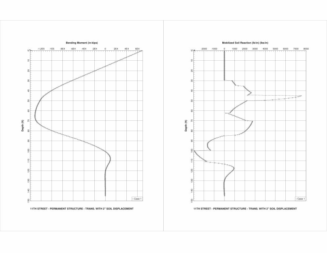
Bending Moment (in-kips)
11TH STREET - PERMANENT STRUCTURE - TRANS. WITH 2" SOIL DISPLACEMENT
Dep
th (
ft)
������ -1.2E5 -1E5 -8E4 -6E4 -4E4 -2E4 0 2E4 4E4 6E4
010
2030
4050
6070
8090
100
110
120
130
140
150 Case 1
Mobilized Soil Reaction (lb/in) (lbs/in)
11TH STREET - PERMANENT STRUCTURE - TRANS. WITH 2" SOIL DISPLACEMENT
Dep
th (
ft)
����� -2000 -1000 0 1000 2000 3000 4000 5000 6000 7000 8000
010
2030
4050
6070
8090
100
110
120
130
140
150 Case 1


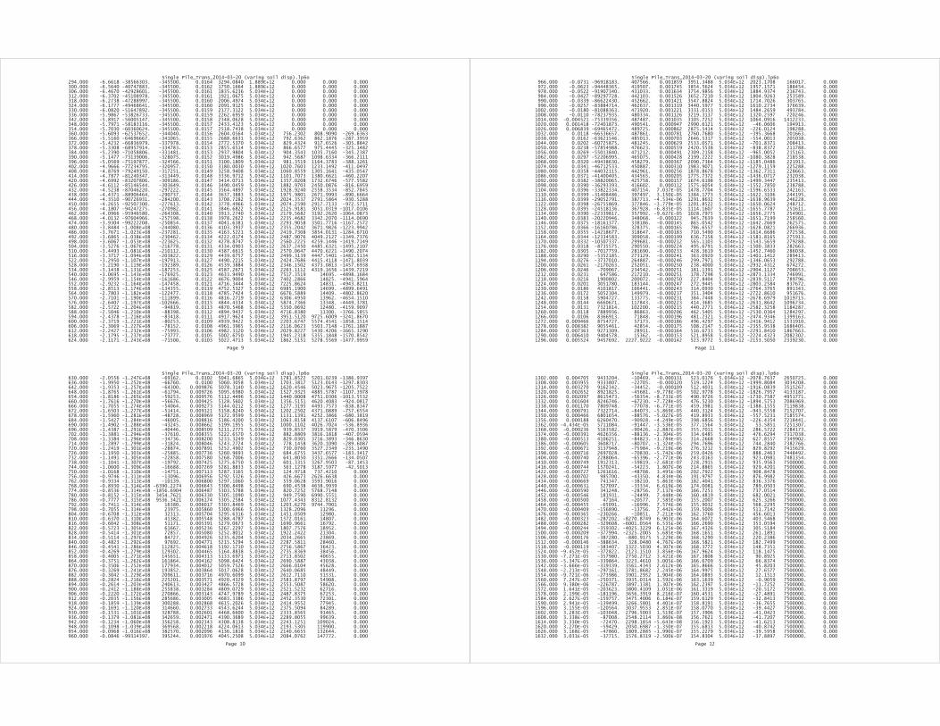
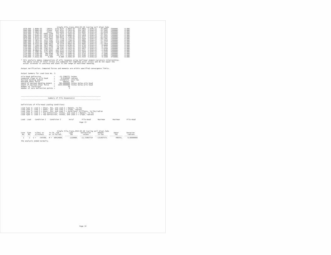
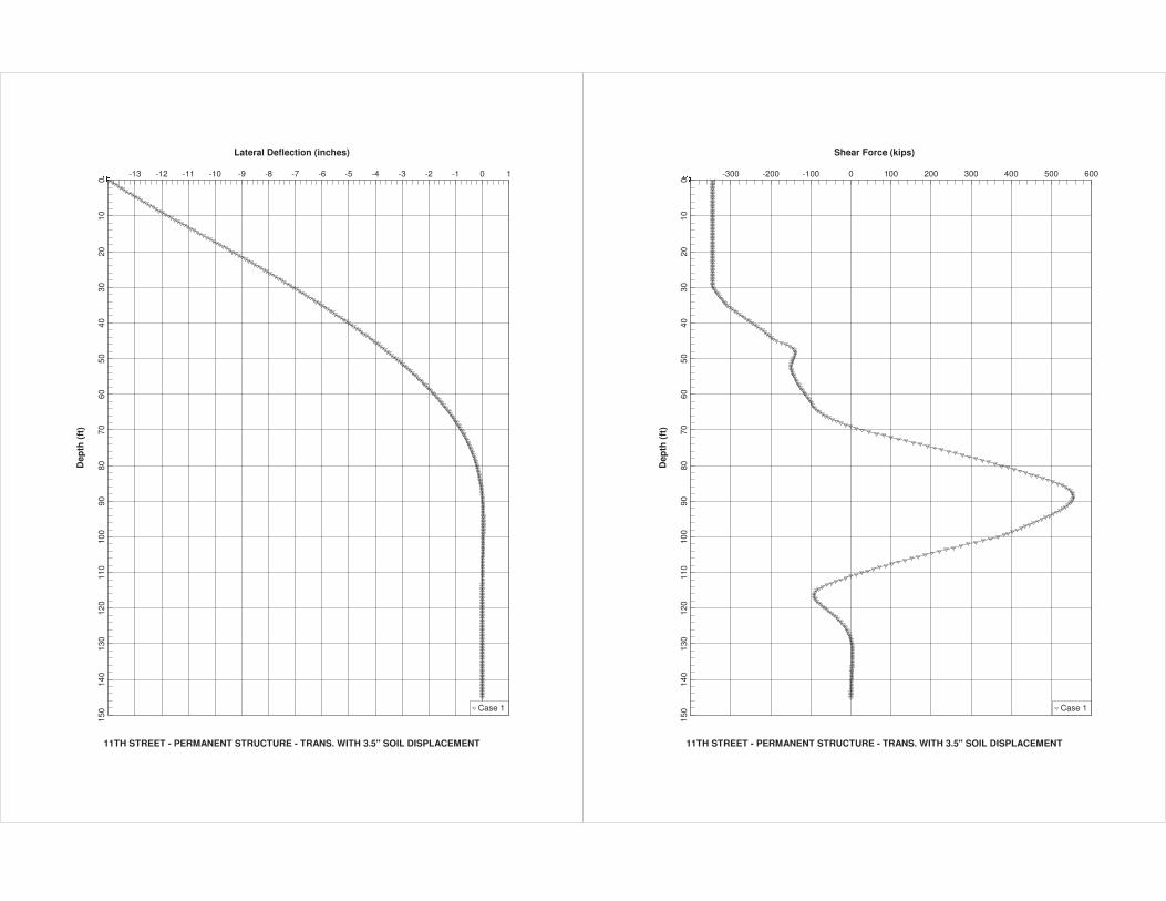
Lateral Deflection (inches)
11TH STREET - PERMANENT STRUCTURE - TRANS. WITH 3.5" SOIL DISPLACEMENT
Dep
th (
ft)
��� -13 -12 -11 -10 -9 -8 -7 -6 -5 -4 -3 -2 -1 0 1
010
2030
4050
6070
8090
100
110
120
130
140
150 Case 1
Shear Force (kips)
11TH STREET - PERMANENT STRUCTURE - TRANS. WITH 3.5" SOIL DISPLACEMENT
Dep
th (
ft)
���� -300 -200 -100 0 100 200 300 400 500 600
010
2030
4050
6070
8090
100
110
120
130
140
150 Case 1
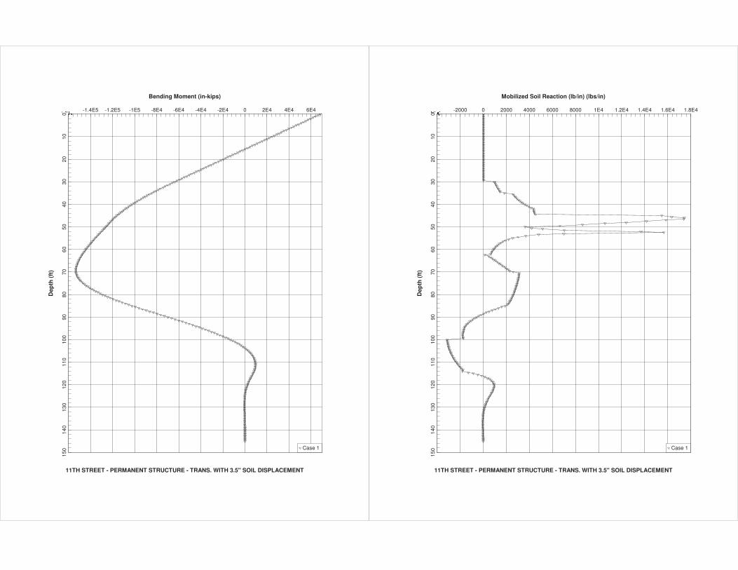
Bending Moment (in-kips)
11TH STREET - PERMANENT STRUCTURE - TRANS. WITH 3.5" SOIL DISPLACEMENT
Dep
th (
ft)
������ -1.4E5 -1.2E5 -1E5 -8E4 -6E4 -4E4 -2E4 0 2E4 4E4 6E4
010
2030
4050
6070
8090
100
110
120
130
140
150 Case 1
Mobilized Soil Reaction (lb/in) (lbs/in)
11TH STREET - PERMANENT STRUCTURE - TRANS. WITH 3.5" SOIL DISPLACEMENT
Dep
th (
ft)
����� -2000 0 2000 4000 6000 8000 1E4 1.2E4 1.4E4 1.6E4 1.8E4
010
2030
4050
6070
8090
100
110
120
130
140
150 Case 1
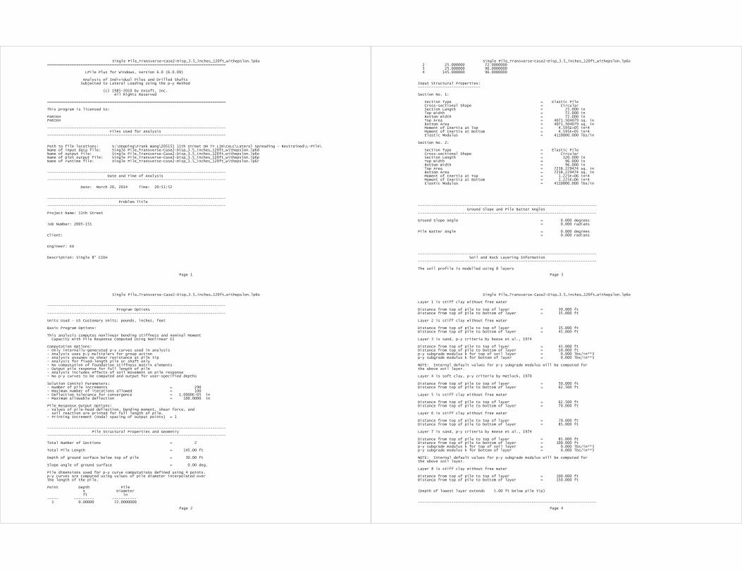


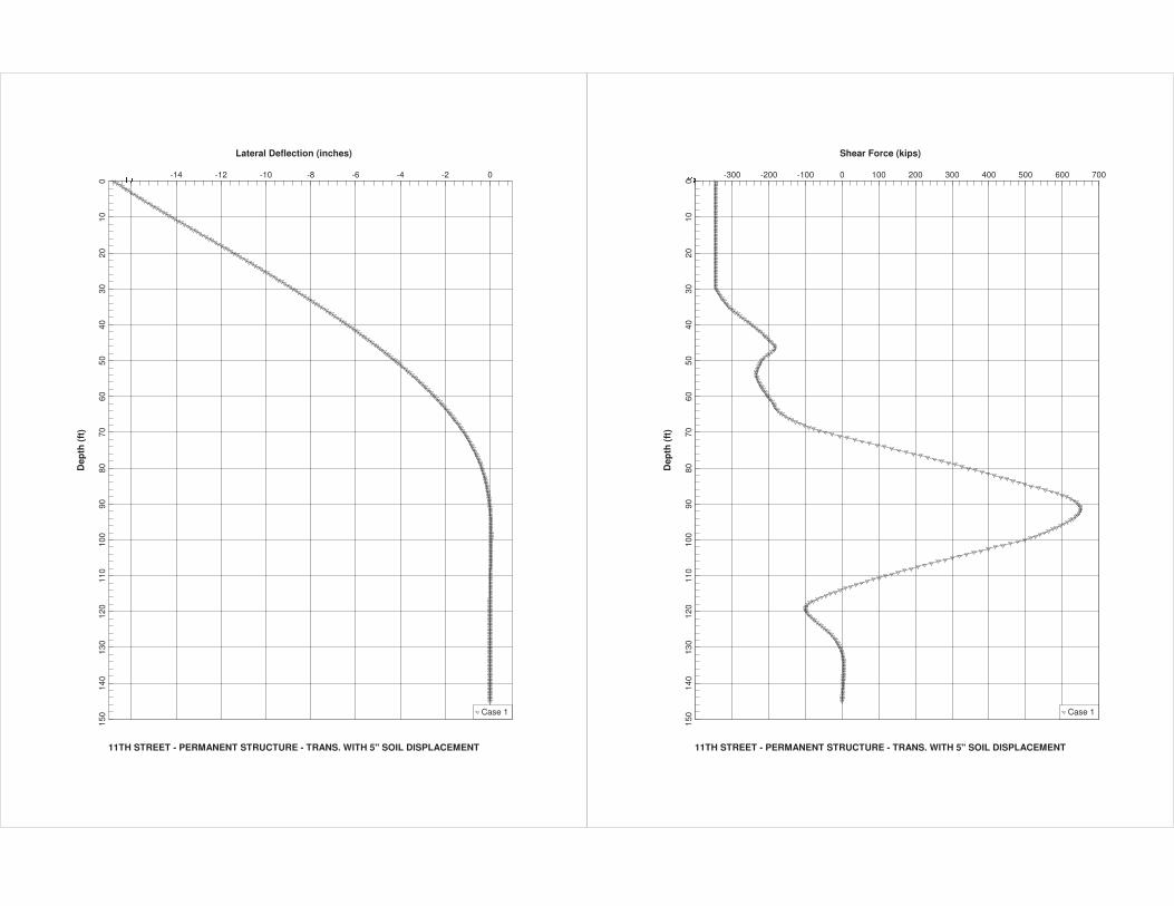
Lateral Deflection (inches)
11TH STREET - PERMANENT STRUCTURE - TRANS. WITH 5" SOIL DISPLACEMENT
Dep
th (
ft)
��� -14 -12 -10 -8 -6 -4 -2 0
010
2030
4050
6070
8090
100
110
120
130
140
150 Case 1
Shear Force (kips)
11TH STREET - PERMANENT STRUCTURE - TRANS. WITH 5" SOIL DISPLACEMENT
Dep
th (
ft)
���� -300 -200 -100 0 100 200 300 400 500 600 700
010
2030
4050
6070
8090
100
110
120
130
140
150 Case 1
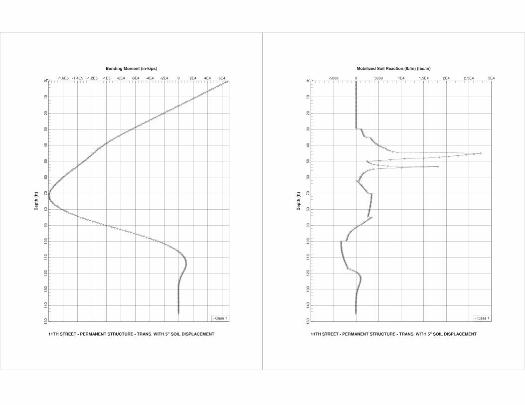
Bending Moment (in-kips)
11TH STREET - PERMANENT STRUCTURE - TRANS. WITH 5" SOIL DISPLACEMENT
Dep
th (
ft)
������ -1.6E5 -1.4E5 -1.2E5 -1E5 -8E4 -6E4 -4E4 -2E4 0 2E4 4E4 6E4
010
2030
4050
6070
8090
100
110
120
130
140
150 Case 1
Mobilized Soil Reaction (lb/in) (lbs/in)
11TH STREET - PERMANENT STRUCTURE - TRANS. WITH 5" SOIL DISPLACEMENT
Dep
th (
ft)
���� -5000 0 5000 1E4 1.5E4 2E4 2.5E4 3E4
010
2030
4050
6070
8090
100
110
120
130
140
150 Case 1
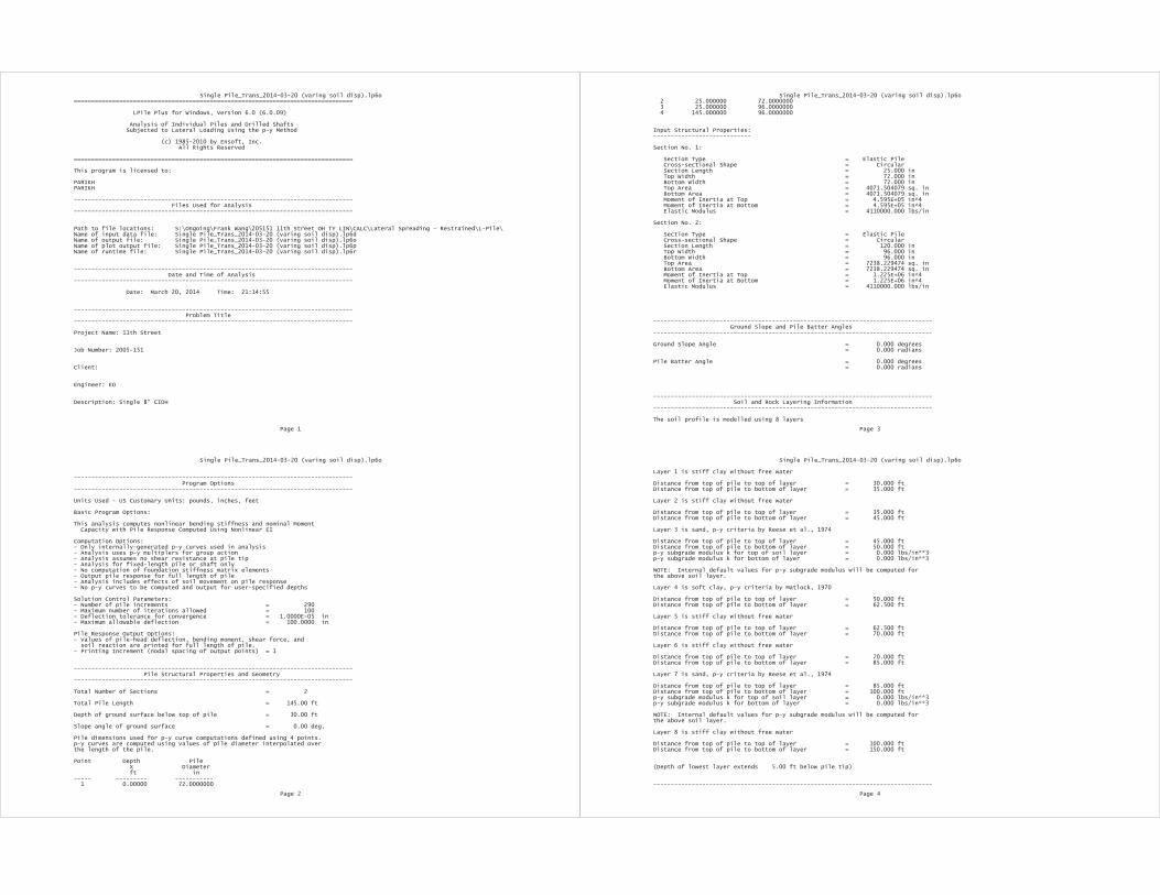
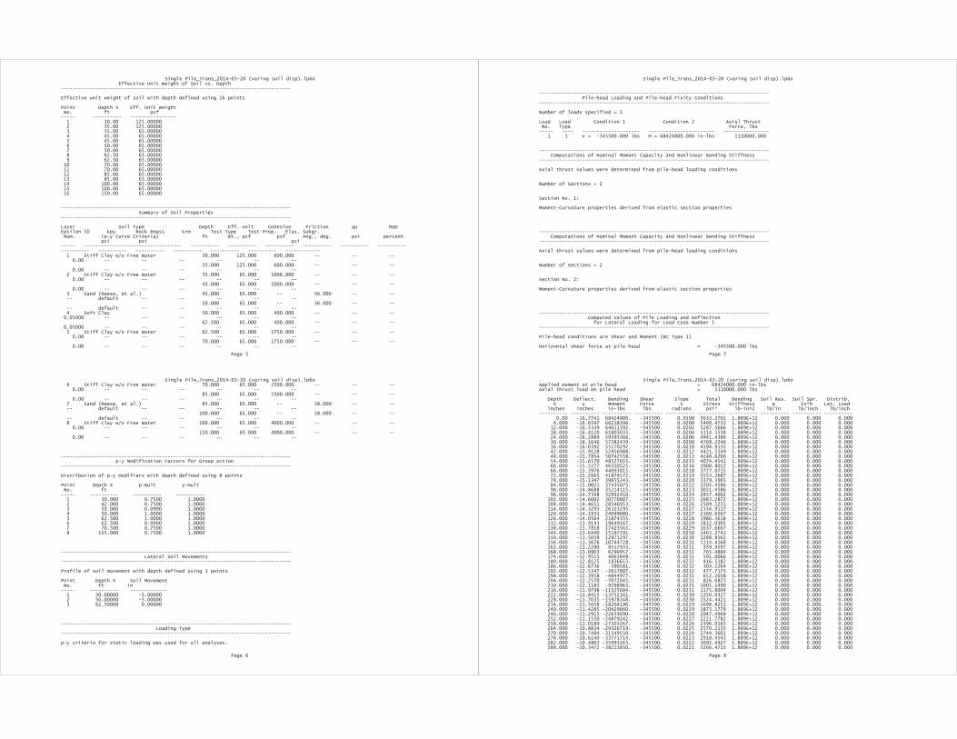


MSE WALL DESIGN
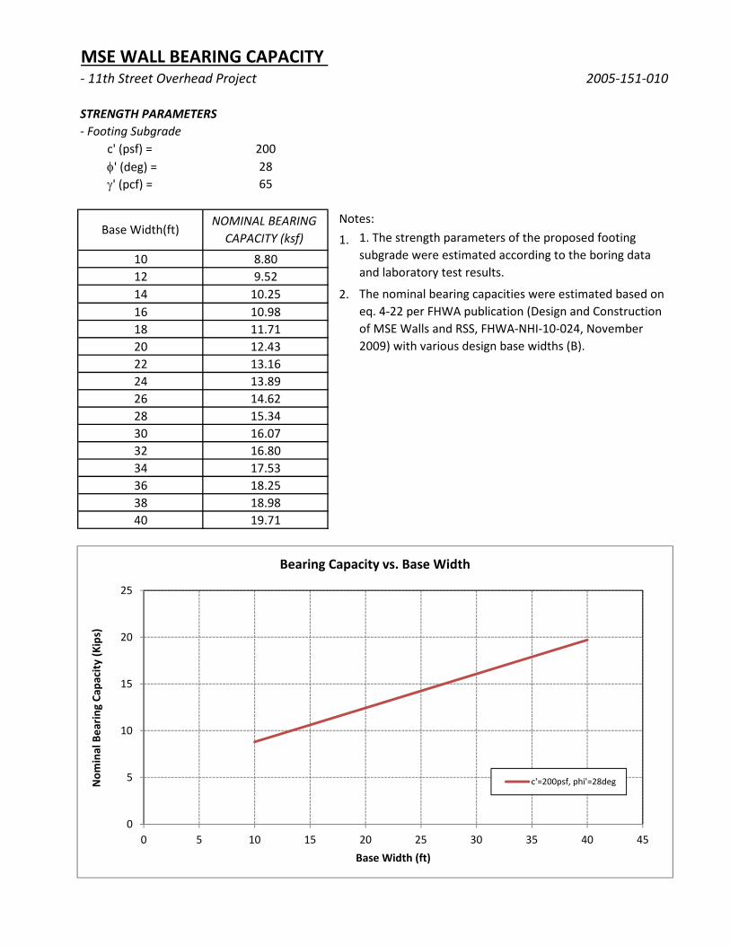
MSE WALL BEARING CAPACITY ‐ 11th Street Overhead Project 2005‐151‐010
STRENGTH PARAMETERS
‐ Footing Subgrade
c' (psf) = 200' (deg) = 28' (pcf) = 65
Notes:
1.10 8.8012 9.5214 10.25 2.16 10.9818 11.7120 12.4322 13.1624 13.8926 14.6228 15.3430 16.0732 16.8034 17.5336 18.2538 18.9840 19.71
The nominal bearing capacities were estimated based on eq. 4‐22 per FHWA publication (Design and Construction of MSE Walls and RSS, FHWA‐NHI‐10‐024, November 2009) with various design base widths (B).
Base Width(ft)NOMINAL BEARING
CAPACITY (ksf) 1. The strength parameters of the proposed footing subgrade were estimated according to the boring data and laboratory test results.
0
5
10
15
20
25
0 5 10 15 20 25 30 35 40 45
Nom
inal Bearin
g Ca
pacity (K
ips)
Base Width (ft)
Bearing Capacity vs. Base Width
c'=200psf, phi'=28deg
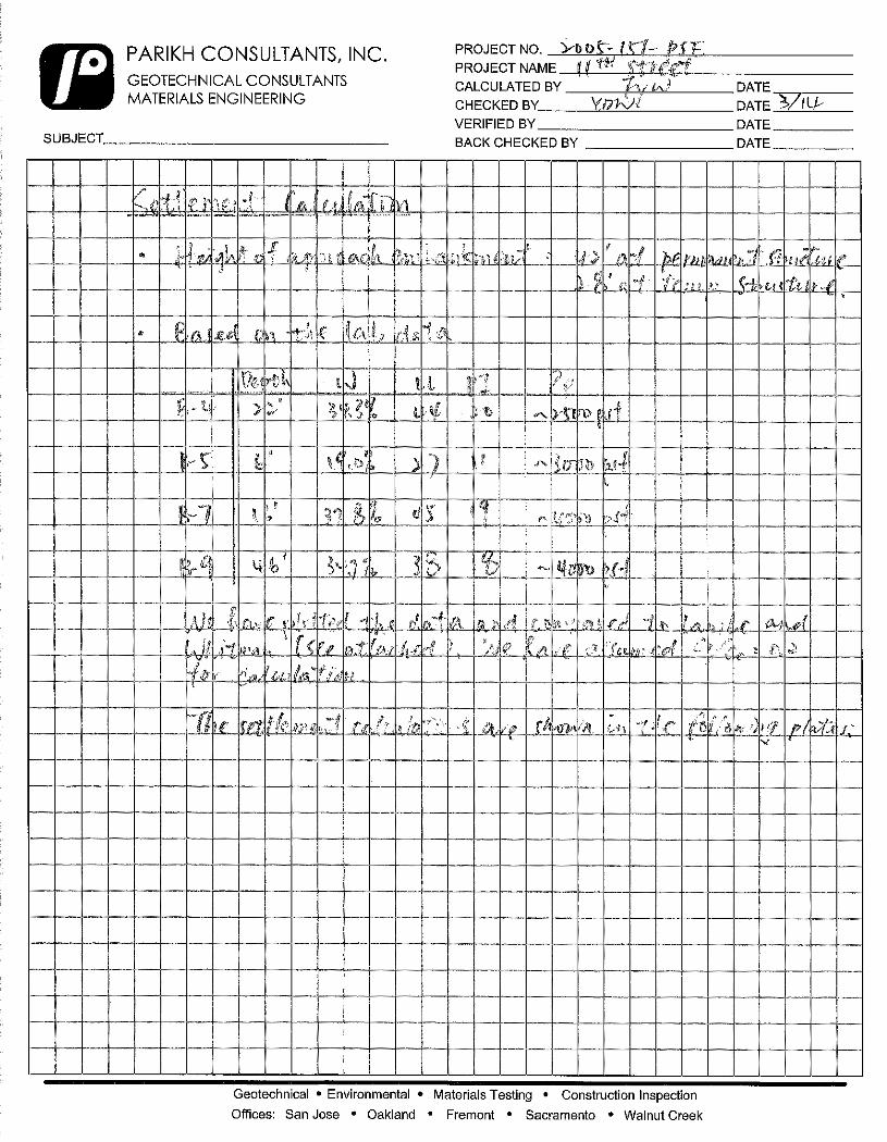
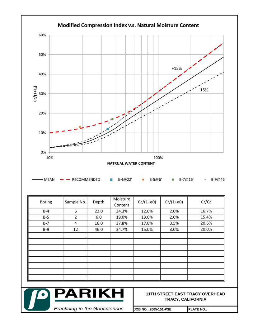
B‐4 6 22.0 34.3% 12.0% 2.0%B‐5 2 6.0 19.0% 13.0% 2.0%B‐7 4 16.0 37.8% 17.0% 3.5%B‐9 12 46.0 34.7% 15.0% 3.0%
JOB NO.: 2005-151-PSE PLATE NO.:
Boring
16.7%15.4%20.6%20.0%
11TH STREET EAST TRACY OVERHEADTRACY, CALIFORNIA
Sample No. DepthMoisture Content
Cc/(1+e0) Cr/(1+e0) Cr/Cc
0%
10%
20%
30%
40%
50%
60%
10% 100%
Cc/(1+e 0)
NATRUAL WATER CONTENT
Modified Compression Index v.s. Natural Moisture Content
MEAN RECOMMENDED B‐4@22' B‐5@6' B‐7@16' B‐9@46'
+15%
‐15%
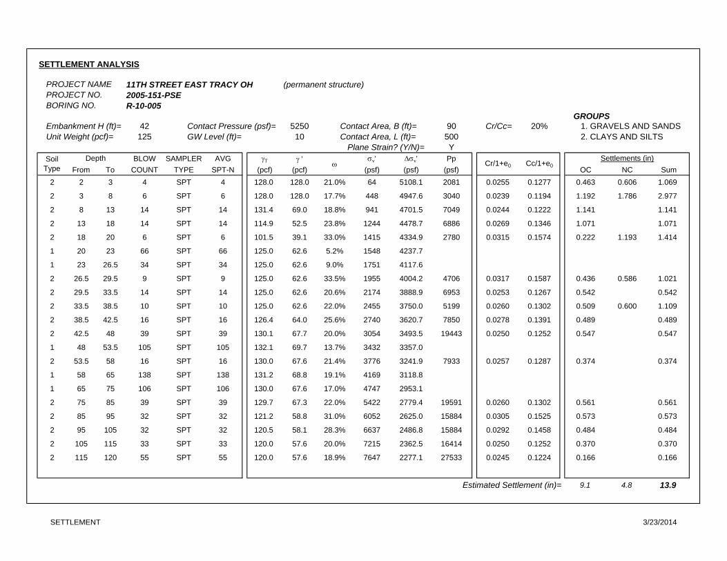
SETTLEMENT ANALYSIS
PROJECT NAME 11TH STREET EAST TRACY OH (permanent structure)PROJECT NO. 2005-151-PSEBORING NO. R-10-005
GROUPSEmbankment H (ft)= 42 Contact Pressure (psf)= 5250 Contact Area, B (ft)= 90 Cr/Cc= 20% 1. GRAVELS AND SANDS Unit Weight (pcf)= 125 GW Level (ft)= 10 Contact Area, L (ft)= 500 2. CLAYS AND SILTS
Plane Strain? (Y/N)= YBLOW SAMPLER AVG ' v' v' Pp
From To COUNT TYPE SPT-N (pcf) (pcf) (psf) (psf) (psf) OC NC Sum2 2 3 4 SPT 4 128.0 128.0 21.0% 64 5108.1 2081 0.0255 0.1277 0.463 0.606 1.069
2 3 8 6 SPT 6 128.0 128.0 17.7% 448 4947.6 3040 0.0239 0.1194 1.192 1.786 2.977
2 8 13 14 SPT 14 131.4 69.0 18.8% 941 4701.5 7049 0.0244 0.1222 1.141 1.141
2 13 18 14 SPT 14 114.9 52.5 23.8% 1244 4478.7 6886 0.0269 0.1346 1.071 1.071
2 18 20 6 SPT 6 101.5 39.1 33.0% 1415 4334.9 2780 0.0315 0.1574 0.222 1.193 1.414
1 20 23 66 SPT 66 125.0 62.6 5.2% 1548 4237.7
1 23 26.5 34 SPT 34 125.0 62.6 9.0% 1751 4117.6
2 26.5 29.5 9 SPT 9 125.0 62.6 33.5% 1955 4004.2 4706 0.0317 0.1587 0.436 0.586 1.021
2 29.5 33.5 14 SPT 14 125.0 62.6 20.6% 2174 3888.9 6953 0.0253 0.1267 0.542 0.542
2 33.5 38.5 10 SPT 10 125.0 62.6 22.0% 2455 3750.0 5199 0.0260 0.1302 0.509 0.600 1.109
2 38.5 42.5 16 SPT 16 126.4 64.0 25.6% 2740 3620.7 7850 0.0278 0.1391 0.489 0.489
2 42.5 48 39 SPT 39 130.1 67.7 20.0% 3054 3493.5 19443 0.0250 0.1252 0.547 0.547
1 48 53.5 105 SPT 105 132.1 69.7 13.7% 3432 3357.0
2 53.5 58 16 SPT 16 130.0 67.6 21.4% 3776 3241.9 7933 0.0257 0.1287 0.374 0.374
1 58 65 138 SPT 138 131.2 68.8 19.1% 4169 3118.8
1 65 75 106 SPT 106 130.0 67.6 17.0% 4747 2953.1
2 75 85 39 SPT 39 129.7 67.3 22.0% 5422 2779.4 19591 0.0260 0.1302 0.561 0.561
2 85 95 32 SPT 32 121.2 58.8 31.0% 6052 2625.0 15884 0.0305 0.1525 0.573 0.573
2 95 105 32 SPT 32 120.5 58.1 28.3% 6637 2486.8 15884 0.0292 0.1458 0.484 0.484
2 105 115 33 SPT 33 120.0 57.6 20.0% 7215 2362.5 16414 0.0250 0.1252 0.370 0.370
2 115 120 55 SPT 55 120.0 57.6 18.9% 7647 2277.1 27533 0.0245 0.1224 0.166 0.166
Estimated Settlement (in)= 9.1 4.8 13.9
SoilType
Depth Cr/1+e0 Cc/1+e0
Settlements (in)
SETTLEMENT 3/23/2014
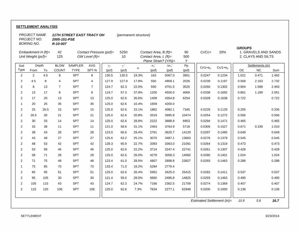
SETTLEMENT ANALYSIS
PROJECT NAME 11TH STREET EAST TRACY OH (permanent structure)PROJECT NO. 2005-151-PSEBORING NO. R-10-007
GROUPSEmbankment H (ft)= 42 Contact Pressure (psf)= 5250 Contact Area, B (ft)= 90 Cr/Cc= 20% 1. GRAVELS AND SANDS Unit Weight (pcf)= 125 GW Level (ft)= 10 Contact Area, L (ft)= 500 2. CLAYS AND SILTS
Plane Strain? (Y/N)= YBLOW SAMPLER AVG ' v' v' Pp
From To COUNT TYPE SPT-N (pcf) (pcf) (psf) (psf) (psf) OC NC Sum2 2 4.5 8 SPT 8 130.5 130.5 19.3% 163 5067.0 3901 0.0247 0.1234 1.021 0.471 1.492
2 4.5 8 4 SPT 4 127.9 127.9 17.8% 550 4909.1 2026 0.0239 0.1197 0.569 2.163 2.732
2 8 13 7 SPT 7 124.7 62.3 22.0% 930 4701.5 3525 0.0260 0.1302 0.904 1.589 2.493
2 13 17 8 SPT 8 119.7 57.3 37.8% 1200 4500.0 4069 0.0338 0.1692 0.861 1.189 2.051
2 17 20 13 SPT 13 125.0 62.6 35.6% 1409 4354.8 6254 0.0328 0.1638 0.722 0.722
1 20 25 35 SPT 35 125.0 62.6 10.4% 1659 4200.0
2 25 26.5 15 SPT 15 125.0 62.6 15.1% 1862 4082.1 7345 0.0226 0.1129 0.205 0.205
2 26.5 30 21 SPT 21 125.0 62.6 20.8% 2019 3995.8 10474 0.0254 0.1272 0.506 0.506
2 30 33 14 SPT 14 125.0 62.6 28.8% 2222 3888.9 6953 0.0294 0.1471 0.465 0.465
2 33 38 11 SPT 11 121.0 58.6 31.1% 2463 3764.9 5718 0.0305 0.1527 0.671 0.339 1.010
2 38 43 28 SPT 28 123.0 60.6 29.4% 2761 3620.7 14129 0.0297 0.1485 0.649 0.649
2 43 48 27 SPT 27 125.6 63.2 25.1% 3070 3487.1 13663 0.0276 0.1379 0.545 0.545
2 48 53 42 SPT 42 128.3 65.9 22.7% 3393 3363.0 21091 0.0264 0.1319 0.473 0.473
2 53 58 45 SPT 45 125.0 62.6 22.2% 3714 3247.4 22741 0.0261 0.1307 0.428 0.428
2 58 71 28 SPT 28 125.0 62.6 26.0% 4278 3058.3 14060 0.0280 0.1401 1.024 1.024
2 71 75 48 SPT 48 123.4 61.0 28.5% 4807 2898.8 23827 0.0293 0.1463 0.288 0.288
1 75 85 70 SPT 70 133.4 71.0 16.2% 5284 2779.4
2 85 95 51 SPT 51 125.0 62.6 26.4% 5952 2625.0 25415 0.0282 0.1411 0.537 0.537
2 95 105 30 SPT 30 121.4 59.0 28.5% 6560 2486.8 14825 0.0293 0.1463 0.490 0.490
2 105 115 43 SPT 43 124.7 62.3 24.7% 7166 2362.5 21709 0.0274 0.1369 0.407 0.407
2 115 120 106 SPT 106 125.0 62.6 7.3% 7634 2277.1 52948 0.0200 0.1000 0.136 0.136
Estimated Settlement (in)= 10.9 5.8 16.7
SoilType
Depth
Settlements (in)Cr/1+e0 Cc/1+e0
SETTLEMENT 3/23/2014
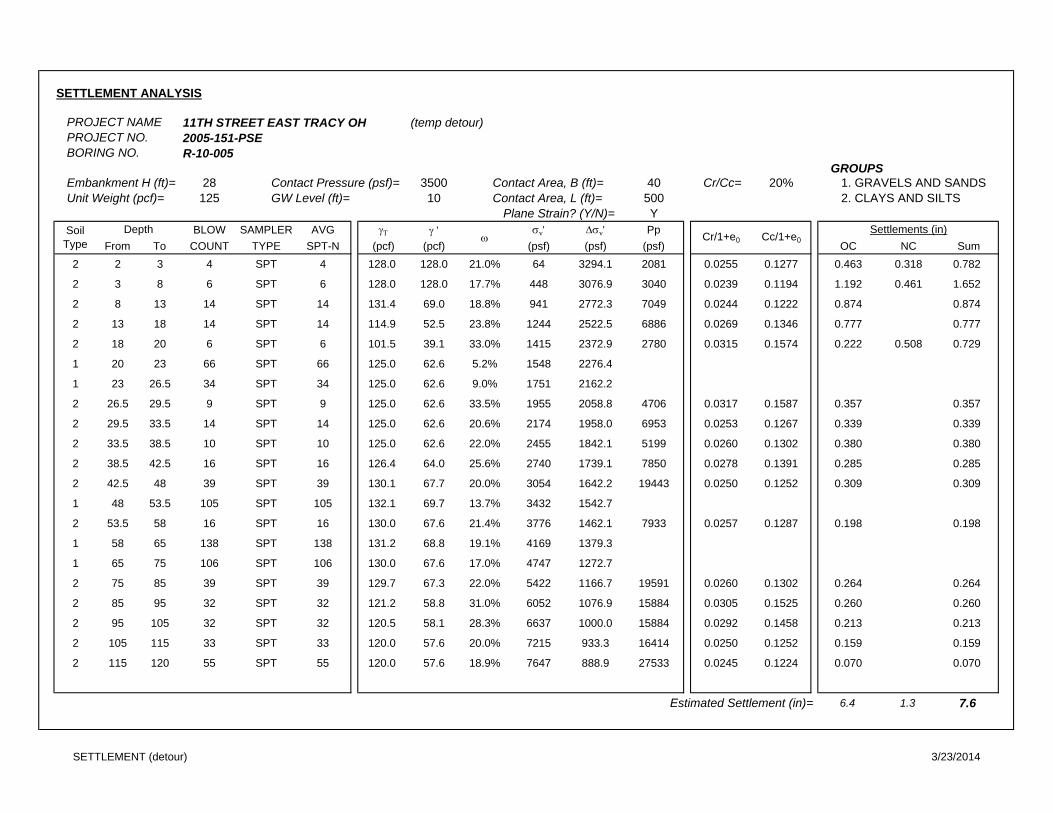
SETTLEMENT ANALYSIS
PROJECT NAME 11TH STREET EAST TRACY OH (temp detour)PROJECT NO. 2005-151-PSEBORING NO. R-10-005
GROUPSEmbankment H (ft)= 28 Contact Pressure (psf)= 3500 Contact Area, B (ft)= 40 Cr/Cc= 20% 1. GRAVELS AND SANDS Unit Weight (pcf)= 125 GW Level (ft)= 10 Contact Area, L (ft)= 500 2. CLAYS AND SILTS
Plane Strain? (Y/N)= YBLOW SAMPLER AVG ' v' v' Pp
From To COUNT TYPE SPT-N (pcf) (pcf) (psf) (psf) (psf) OC NC Sum2 2 3 4 SPT 4 128.0 128.0 21.0% 64 3294.1 2081 0.0255 0.1277 0.463 0.318 0.782
2 3 8 6 SPT 6 128.0 128.0 17.7% 448 3076.9 3040 0.0239 0.1194 1.192 0.461 1.652
2 8 13 14 SPT 14 131.4 69.0 18.8% 941 2772.3 7049 0.0244 0.1222 0.874 0.874
2 13 18 14 SPT 14 114.9 52.5 23.8% 1244 2522.5 6886 0.0269 0.1346 0.777 0.777
2 18 20 6 SPT 6 101.5 39.1 33.0% 1415 2372.9 2780 0.0315 0.1574 0.222 0.508 0.729
1 20 23 66 SPT 66 125.0 62.6 5.2% 1548 2276.4
1 23 26.5 34 SPT 34 125.0 62.6 9.0% 1751 2162.2
2 26.5 29.5 9 SPT 9 125.0 62.6 33.5% 1955 2058.8 4706 0.0317 0.1587 0.357 0.357
2 29.5 33.5 14 SPT 14 125.0 62.6 20.6% 2174 1958.0 6953 0.0253 0.1267 0.339 0.339
2 33.5 38.5 10 SPT 10 125.0 62.6 22.0% 2455 1842.1 5199 0.0260 0.1302 0.380 0.380
2 38.5 42.5 16 SPT 16 126.4 64.0 25.6% 2740 1739.1 7850 0.0278 0.1391 0.285 0.285
2 42.5 48 39 SPT 39 130.1 67.7 20.0% 3054 1642.2 19443 0.0250 0.1252 0.309 0.309
1 48 53.5 105 SPT 105 132.1 69.7 13.7% 3432 1542.7
2 53.5 58 16 SPT 16 130.0 67.6 21.4% 3776 1462.1 7933 0.0257 0.1287 0.198 0.198
1 58 65 138 SPT 138 131.2 68.8 19.1% 4169 1379.3
1 65 75 106 SPT 106 130.0 67.6 17.0% 4747 1272.7
2 75 85 39 SPT 39 129.7 67.3 22.0% 5422 1166.7 19591 0.0260 0.1302 0.264 0.264
2 85 95 32 SPT 32 121.2 58.8 31.0% 6052 1076.9 15884 0.0305 0.1525 0.260 0.260
2 95 105 32 SPT 32 120.5 58.1 28.3% 6637 1000.0 15884 0.0292 0.1458 0.213 0.213
2 105 115 33 SPT 33 120.0 57.6 20.0% 7215 933.3 16414 0.0250 0.1252 0.159 0.159
2 115 120 55 SPT 55 120.0 57.6 18.9% 7647 888.9 27533 0.0245 0.1224 0.070 0.070
Estimated Settlement (in)= 6.4 1.3 7.6
SoilType
Depth Cr/1+e0 Cc/1+e0
Settlements (in)
SETTLEMENT (detour) 3/23/2014
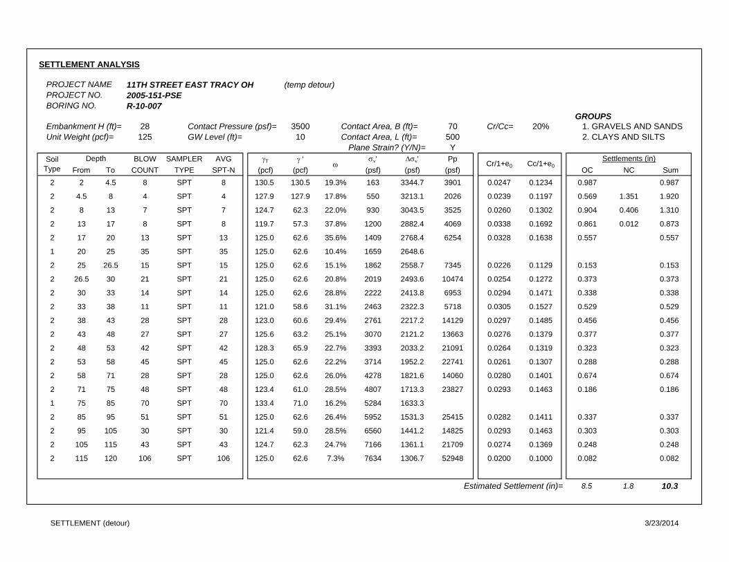
SETTLEMENT ANALYSIS
PROJECT NAME 11TH STREET EAST TRACY OH (temp detour)PROJECT NO. 2005-151-PSEBORING NO. R-10-007
GROUPSEmbankment H (ft)= 28 Contact Pressure (psf)= 3500 Contact Area, B (ft)= 70 Cr/Cc= 20% 1. GRAVELS AND SANDS Unit Weight (pcf)= 125 GW Level (ft)= 10 Contact Area, L (ft)= 500 2. CLAYS AND SILTS
Plane Strain? (Y/N)= YBLOW SAMPLER AVG ' v' v' Pp
From To COUNT TYPE SPT-N (pcf) (pcf) (psf) (psf) (psf) OC NC Sum2 2 4.5 8 SPT 8 130.5 130.5 19.3% 163 3344.7 3901 0.0247 0.1234 0.987 0.987
2 4.5 8 4 SPT 4 127.9 127.9 17.8% 550 3213.1 2026 0.0239 0.1197 0.569 1.351 1.920
2 8 13 7 SPT 7 124.7 62.3 22.0% 930 3043.5 3525 0.0260 0.1302 0.904 0.406 1.310
2 13 17 8 SPT 8 119.7 57.3 37.8% 1200 2882.4 4069 0.0338 0.1692 0.861 0.012 0.873
2 17 20 13 SPT 13 125.0 62.6 35.6% 1409 2768.4 6254 0.0328 0.1638 0.557 0.557
1 20 25 35 SPT 35 125.0 62.6 10.4% 1659 2648.6
2 25 26.5 15 SPT 15 125.0 62.6 15.1% 1862 2558.7 7345 0.0226 0.1129 0.153 0.153
2 26.5 30 21 SPT 21 125.0 62.6 20.8% 2019 2493.6 10474 0.0254 0.1272 0.373 0.373
2 30 33 14 SPT 14 125.0 62.6 28.8% 2222 2413.8 6953 0.0294 0.1471 0.338 0.338
2 33 38 11 SPT 11 121.0 58.6 31.1% 2463 2322.3 5718 0.0305 0.1527 0.529 0.529
2 38 43 28 SPT 28 123.0 60.6 29.4% 2761 2217.2 14129 0.0297 0.1485 0.456 0.456
2 43 48 27 SPT 27 125.6 63.2 25.1% 3070 2121.2 13663 0.0276 0.1379 0.377 0.377
2 48 53 42 SPT 42 128.3 65.9 22.7% 3393 2033.2 21091 0.0264 0.1319 0.323 0.323
2 53 58 45 SPT 45 125.0 62.6 22.2% 3714 1952.2 22741 0.0261 0.1307 0.288 0.288
2 58 71 28 SPT 28 125.0 62.6 26.0% 4278 1821.6 14060 0.0280 0.1401 0.674 0.674
2 71 75 48 SPT 48 123.4 61.0 28.5% 4807 1713.3 23827 0.0293 0.1463 0.186 0.186
1 75 85 70 SPT 70 133.4 71.0 16.2% 5284 1633.3
2 85 95 51 SPT 51 125.0 62.6 26.4% 5952 1531.3 25415 0.0282 0.1411 0.337 0.337
2 95 105 30 SPT 30 121.4 59.0 28.5% 6560 1441.2 14825 0.0293 0.1463 0.303 0.303
2 105 115 43 SPT 43 124.7 62.3 24.7% 7166 1361.1 21709 0.0274 0.1369 0.248 0.248
2 115 120 106 SPT 106 125.0 62.6 7.3% 7634 1306.7 52948 0.0200 0.1000 0.082 0.082
Estimated Settlement (in)= 8.5 1.8 10.3
SoilType
Depth
Settlements (in)Cr/1+e0 Cc/1+e0
SETTLEMENT (detour) 3/23/2014
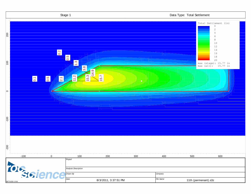
0.2
0.5
1.3
3.8
14.9
15.7
15.7
15.3
11.2
2.1
0.5
0.1
200
100
0-1
00-2
00
-100 0 100 200 300 400 500 600
Total Settlement (in) 0 2 4 6 8 10 12 14 16 18 20
max (stage): 15.77 inmax (all): 15.77 in
Data Type: Total SettlementStage 1
Analysis Description
CompanyDrawn By
File Name 11th (permenant).s3zDate 8/3/2011, 3:37:51 PM
Project
SETTLE3D 2.016
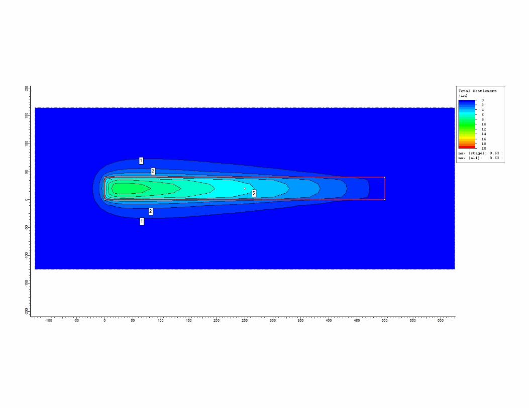
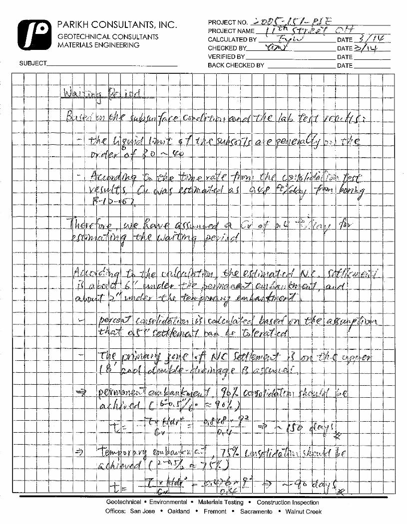
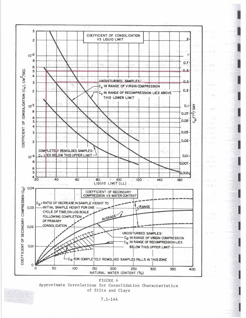
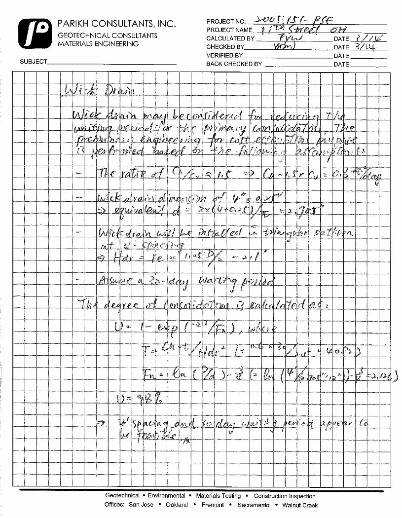
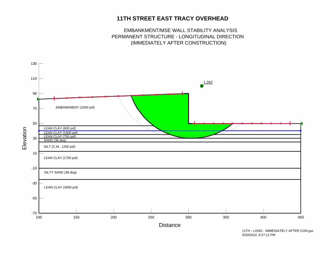
1.262
11TH STREET EAST TRACY OVERHEAD
EMBANKMENT/MSE WALL STABILITY ANALYSIS PERMANENT STRUCTURE - LONGITUDINAL DIRECTION (IMMEDIATELY AFTER CONSTRUCTION)
LEAN CLAY (750 psf)
LEAN CLAY (600 psf)
EMBANKMENT (1500 psf)
LEAN CLAY (1500 psf)
SAND (36 deg)
LEAN CLAY (1750 psf)
SILT (C.M., 1250 psf)
SILTY SAND (38 deg)
11TH - LONG - IMMEDIATELY AFTER CON.gsz3/20/2014, 9:27:12 PM
LEAN CLAY (4000 psf)
Distance100 150 200 250 300 350 400 450
Ele
vatio
n
-70
-50
-30
-10
10
30
50
70
90
110
130
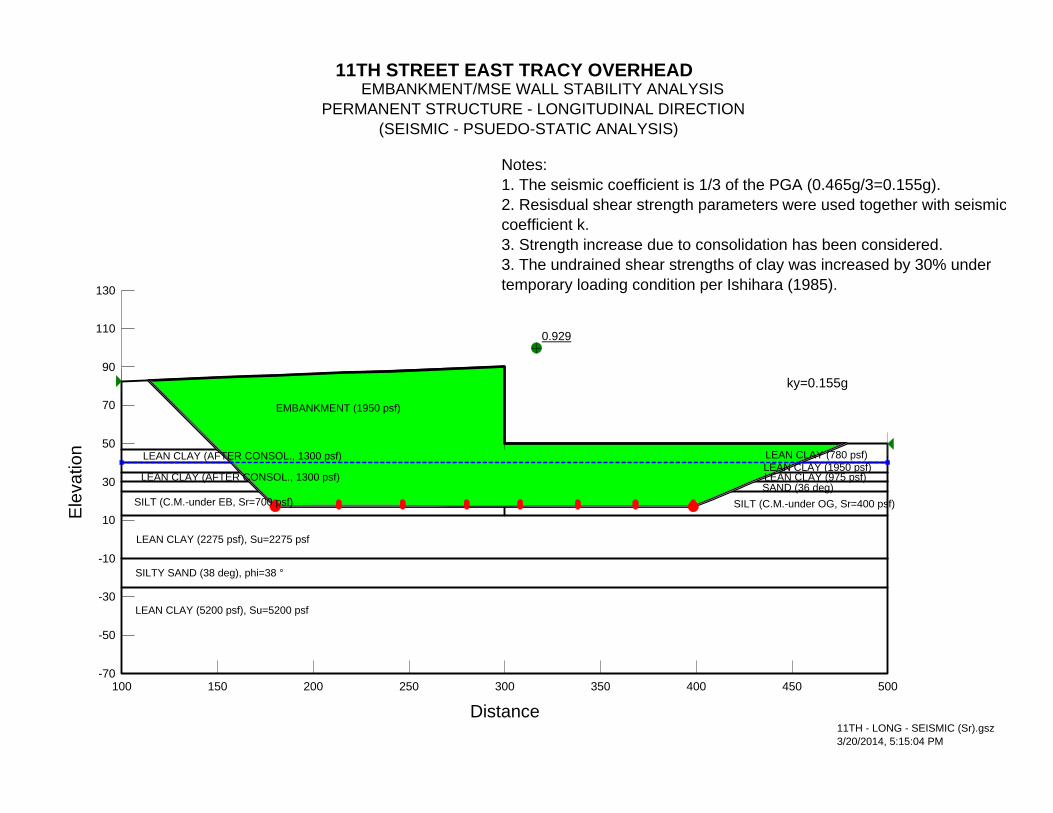
0.929
11TH STREET EAST TRACY OVERHEAD EMBANKMENT/MSE WALL STABILITY ANALYSIS PERMANENT STRUCTURE - LONGITUDINAL DIRECTION (SEISMIC - PSUEDO-STATIC ANALYSIS)
LEAN CLAY (AFTER CONSOL., 1300 psf)
SILT (C.M.-under EB, Sr=700 psf)
LEAN CLAY (780 psf)
EMBANKMENT (1950 psf)
LEAN CLAY (AFTER CONSOL., 1300 psf)
LEAN CLAY (975 psf)SAND (36 deg)
LEAN CLAY (2275 psf), Su=2275 psf
SILT (C.M.-under OG, Sr=400 psf)
SILTY SAND (38 deg), phi=38 °
11TH - LONG - SEISMIC (Sr).gsz3/20/2014, 5:15:04 PM
ky=0.155g
LEAN CLAY (5200 psf), Su=5200 psf
LEAN CLAY (1950 psf)
Notes:1. The seismic coefficient is 1/3 of the PGA (0.465g/3=0.155g).2. Resisdual shear strength parameters were used together with seismiccoefficient k.3. Strength increase due to consolidation has been considered. 3. The undrained shear strengths of clay was increased by 30% under temporary loading condition per Ishihara (1985).
Distance100 150 200 250 300 350 400 450 500
Ele
vatio
n
-70
-50
-30
-10
10
30
50
70
90
110
130
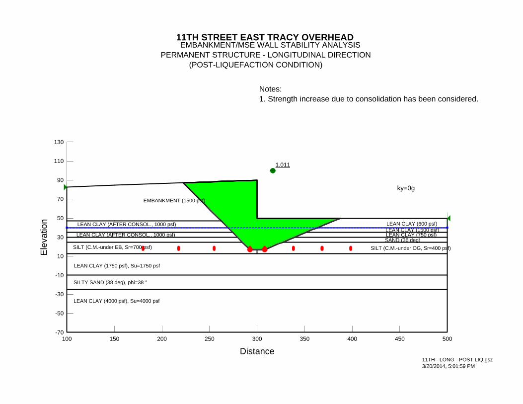
1.011
11TH STREET EAST TRACY OVERHEAD EMBANKMENT/MSE WALL STABILITY ANALYSIS PERMANENT STRUCTURE - LONGITUDINAL DIRECTION (POST-LIQUEFACTION CONDITION)
LEAN CLAY (AFTER CONSOL., 1000 psf)
SILT (C.M.-under EB, Sr=700 psf)
LEAN CLAY (600 psf)
EMBANKMENT (1500 psf)
LEAN CLAY (AFTER CONSOL., 1000 psf)
LEAN CLAY (750 psf)SAND (36 deg)
LEAN CLAY (1750 psf), Su=1750 psf
SILT (C.M.-under OG, Sr=400 psf)
SILTY SAND (38 deg), phi=38 °
11TH - LONG - POST LIQ.gsz3/20/2014, 5:01:59 PM
ky=0g
LEAN CLAY (4000 psf), Su=4000 psf
LEAN CLAY (1500 psf)
Notes:1. Strength increase due to consolidation has been considered.
Distance100 150 200 250 300 350 400 450 500
Ele
vatio
n
-70
-50
-30
-10
10
30
50
70
90
110
130
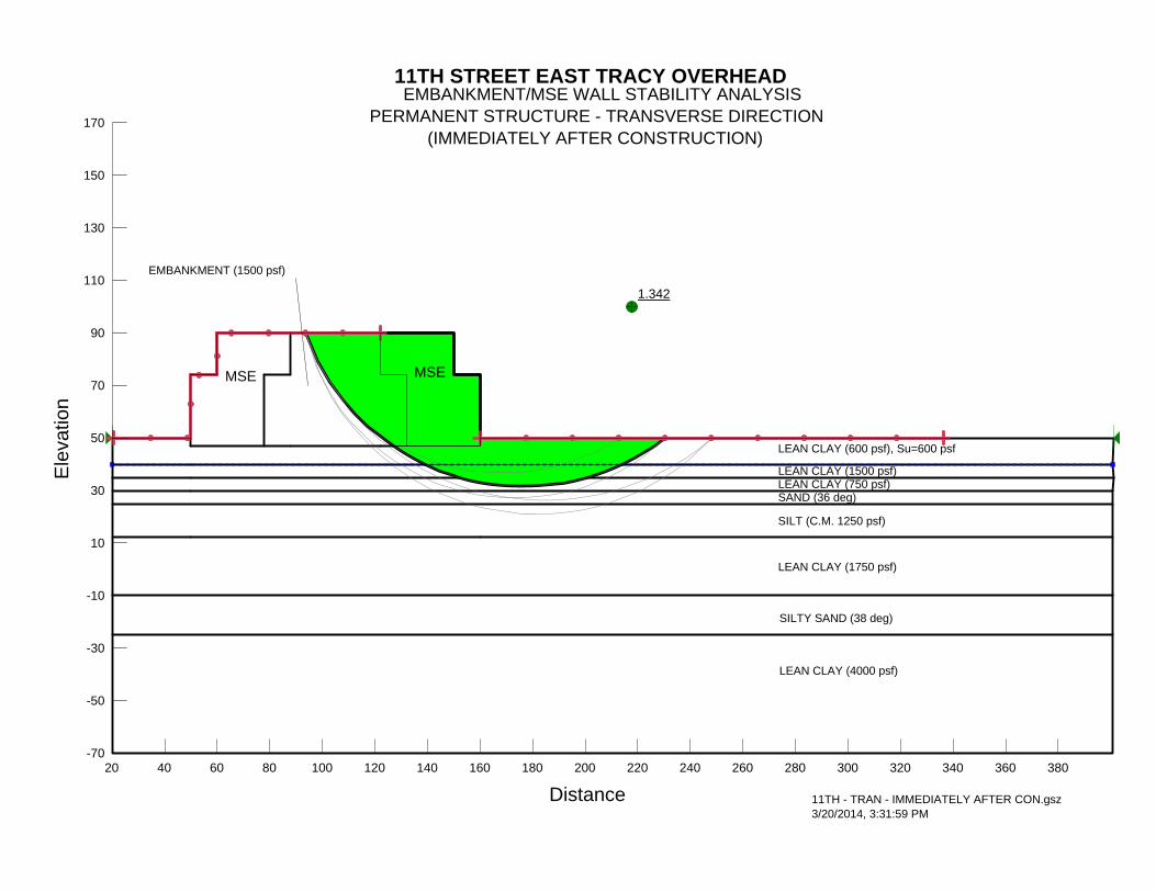
1.342
11TH STREET EAST TRACY OVERHEAD EMBANKMENT/MSE WALL STABILITY ANALYSISPERMANENT STRUCTURE - TRANSVERSE DIRECTION (IMMEDIATELY AFTER CONSTRUCTION)
MSE MSE
EMBANKMENT (1500 psf)
LEAN CLAY (600 psf), Su=600 psf
LEAN CLAY (1500 psf)
SAND (36 deg)
LEAN CLAY (1750 psf)
SILT (C.M. 1250 psf)
SILTY SAND (38 deg)
11TH - TRAN - IMMEDIATELY AFTER CON.gsz3/20/2014, 3:31:59 PM
LEAN CLAY (4000 psf)
LEAN CLAY (750 psf)
Distance20 40 60 80 100 120 140 160 180 200 220 240 260 280 300 320 340 360 380
Ele
vatio
n
-70
-50
-30
-10
10
30
50
70
90
110
130
150
170
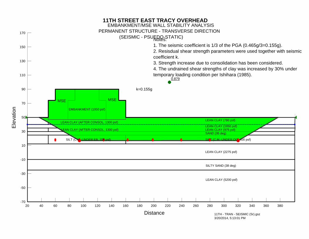
0.879
11TH STREET EAST TRACY OVERHEAD EMBANKMENT/MSE WALL STABILITY ANALYSISPERMANENT STRUCTURE - TRANSVERSE DIRECTION (SEISMIC - PSUEDO-STATIC)
MSE MSE
EMBANKMENT (1950 psf)
LEAN CLAY (780 psf)
LEAN CLAY (1950 psf)
SAND (36 deg)
LEAN CLAY (2275 psf)
SILT (C.M.-UNDER OG, 400 psf)
SILTY SAND (38 deg)
11TH - TRAN - SEISMIC (Sr).gsz3/20/2014, 5:13:01 PM
k=0.155g
LEAN CLAY (5200 psf)
LEAN CLAY (AFTER CONSOL, 1300 psf)
LEAN CLAY (975 psf)
SILT (C.M.-UNDER EB, 700 psf)
LEAN CLAY (AFTER CONSOL, 1300 psf)
Notes:1. The seismic coefficient is 1/3 of the PGA (0.465g/3=0.155g).2. Resisdual shear strength parameters were used together with seismic coefficient k.3. Strength increase due to consolidation has been considered. 4. The undrained shear strengths of clay was increased by 30% under temporary loading condition per Ishihara (1985).
Distance20 40 60 80 100 120 140 160 180 200 220 240 260 280 300 320 340 360 380
Ele
vatio
n
-70
-50
-30
-10
10
30
50
70
90
110
130
150
170
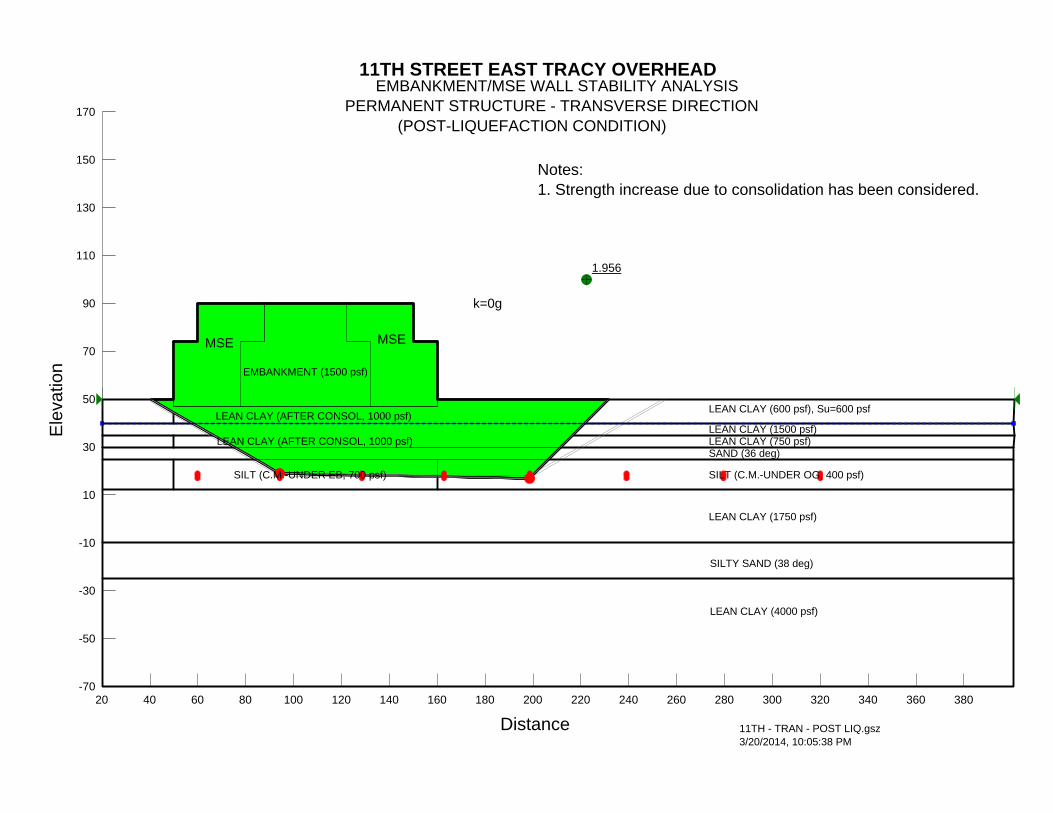
1.956
11TH STREET EAST TRACY OVERHEAD EMBANKMENT/MSE WALL STABILITY ANALYSISPERMANENT STRUCTURE - TRANSVERSE DIRECTION (POST-LIQUEFACTION CONDITION)
MSE MSE
EMBANKMENT (1500 psf)
LEAN CLAY (600 psf), Su=600 psf
LEAN CLAY (1500 psf)
SAND (36 deg)
LEAN CLAY (1750 psf)
SILT (C.M.-UNDER OG, 400 psf)
SILTY SAND (38 deg)
11TH - TRAN - POST LIQ.gsz3/20/2014, 10:05:38 PM
k=0g
LEAN CLAY (4000 psf)
LEAN CLAY (AFTER CONSOL, 1000 psf)
LEAN CLAY (750 psf)
SILT (C.M.-UNDER EB, 700 psf)
LEAN CLAY (AFTER CONSOL, 1000 psf)
Notes:1. Strength increase due to consolidation has been considered.
Distance20 40 60 80 100 120 140 160 180 200 220 240 260 280 300 320 340 360 380
Ele
vatio
n
-70
-50
-30
-10
10
30
50
70
90
110
130
150
170
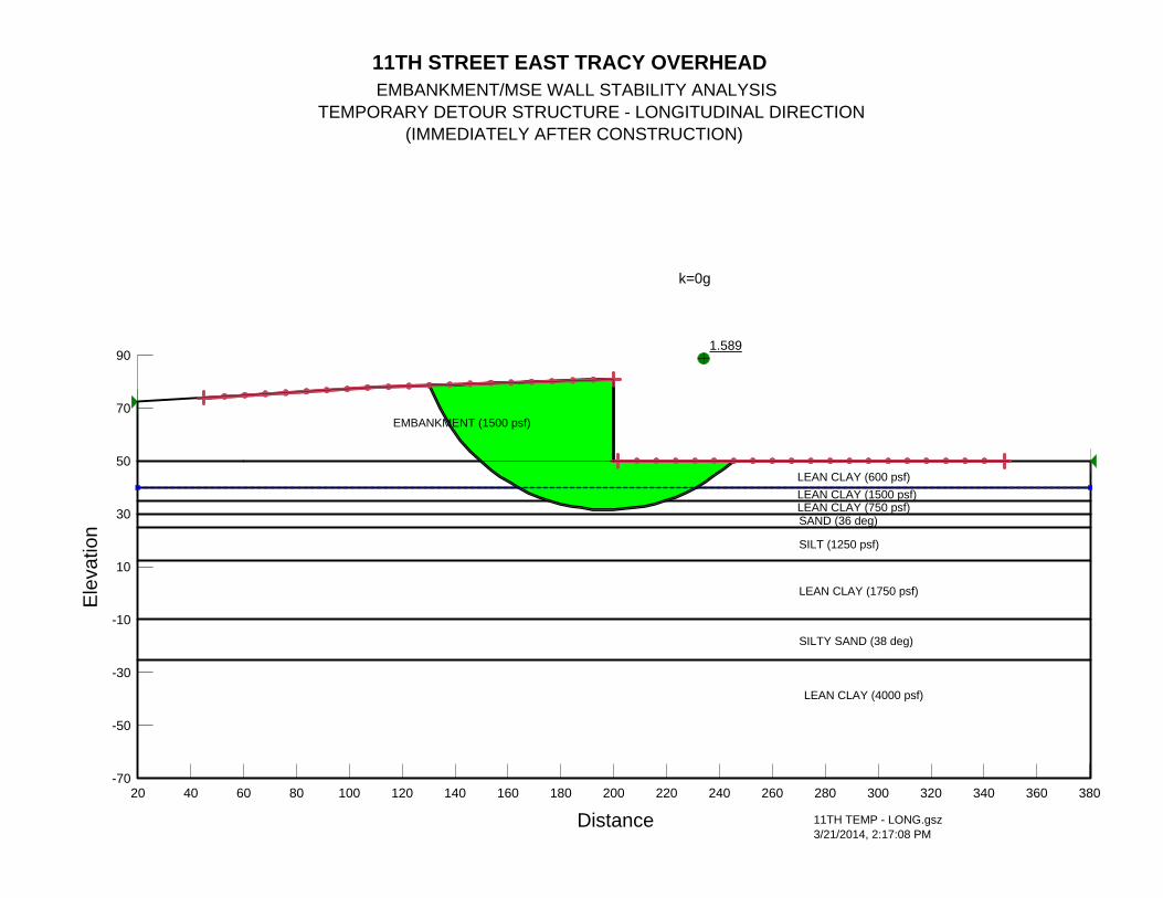
1.589
11TH STREET EAST TRACY OVERHEAD EMBANKMENT/MSE WALL STABILITY ANALYSISTEMPORARY DETOUR STRUCTURE - LONGITUDINAL DIRECTION (IMMEDIATELY AFTER CONSTRUCTION)
EMBANKMENT (1500 psf)
LEAN CLAY (750 psf)
LEAN CLAY (600 psf)LEAN CLAY (1500 psf)
SAND (36 deg)
LEAN CLAY (1750 psf)
SILT (1250 psf)
SILTY SAND (38 deg)
11TH TEMP - LONG.gsz3/21/2014, 2:17:08 PM
k=0g
LEAN CLAY (4000 psf)
Distance20 40 60 80 100 120 140 160 180 200 220 240 260 280 300 320 340 360 380
Ele
vatio
n
-70
-50
-30
-10
10
30
50
70
90

1.294
11TH STREET EAST TRACY OVERHEAD EMBANKMENT/MSE WALL STABILITY ANALYSISTEMPORARY DETOUR STRUCTURE - LONGITUDINAL DIRECTION (IMMEDIATELY AFTER CONSTRUCTION)
EMBANKMENT (1500 psf)
LEAN CLAY (750 psf)
LEAN CLAY (600 psf)LEAN CLAY (1500 psf)
SAND (36 deg)
LEAN CLAY (1750 psf)
SILT (1250 psf)
SILTY SAND (38 deg)
11TH TEMP - LONG - SEISMIC.gsz3/21/2014, 2:18:59 PM
k=0.0756g
LEAN CLAY (4000 psf)
Distance20 40 60 80 100 120 140 160 180 200 220 240 260 280 300 320 340 360 380
Ele
vatio
n
-70
-50
-30
-10
10
30
50
70
90
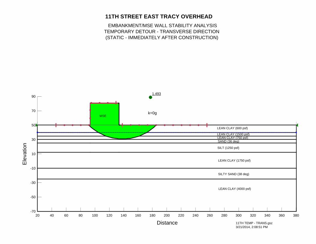
1.493
11TH STREET EAST TRACY OVERHEAD EMBANKMENT/MSE WALL STABILITY ANALYSIS TEMPORARY DETOUR - TRANSVERSE DIRECTION (STATIC - IMMEDIATELY AFTER CONSTRUCTION)
MSE
LEAN CLAY (750 psf)
LEAN CLAY (600 psf)
LEAN CLAY (1500 psf)
SAND (36 deg)
LEAN CLAY (1750 psf)
SILT (1250 psf)
SILTY SAND (38 deg)
11TH TEMP - TRANS.gsz3/21/2014, 2:08:51 PM
k=0g
LEAN CLAY (4000 psf)
Distance20 40 60 80 100 120 140 160 180 200 220 240 260 280 300 320 340 360 380
Ele
vatio
n
-70
-50
-30
-10
10
30
50
70
90
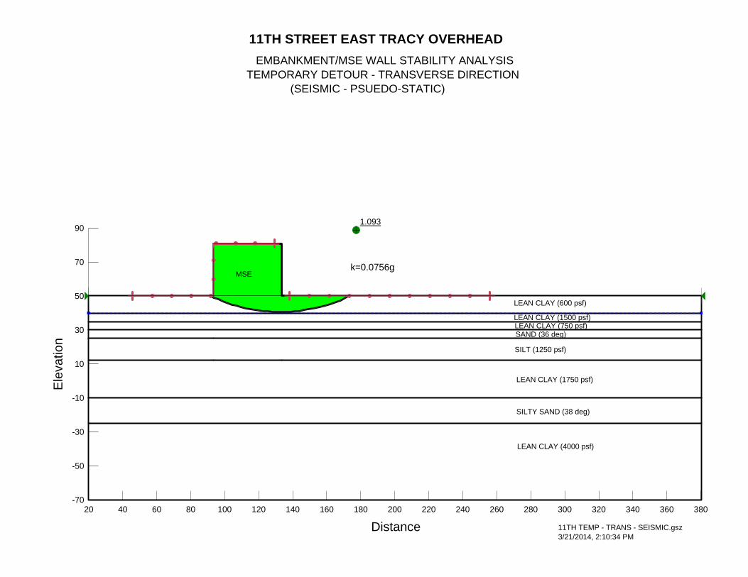
1.093
11TH STREET EAST TRACY OVERHEAD EMBANKMENT/MSE WALL STABILITY ANALYSIS TEMPORARY DETOUR - TRANSVERSE DIRECTION (SEISMIC - PSUEDO-STATIC)
MSE
LEAN CLAY (750 psf)
LEAN CLAY (600 psf)
LEAN CLAY (1500 psf)
SAND (36 deg)
LEAN CLAY (1750 psf)
SILT (1250 psf)
SILTY SAND (38 deg)
11TH TEMP - TRANS - SEISMIC.gsz3/21/2014, 2:10:34 PM
k=0.0756g
LEAN CLAY (4000 psf)
Distance20 40 60 80 100 120 140 160 180 200 220 240 260 280 300 320 340 360 380
Ele
vatio
n
-70
-50
-30
-10
10
30
50
70
90

RETAINING WALL NO. 5
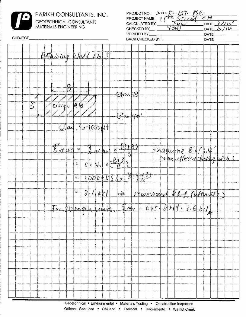
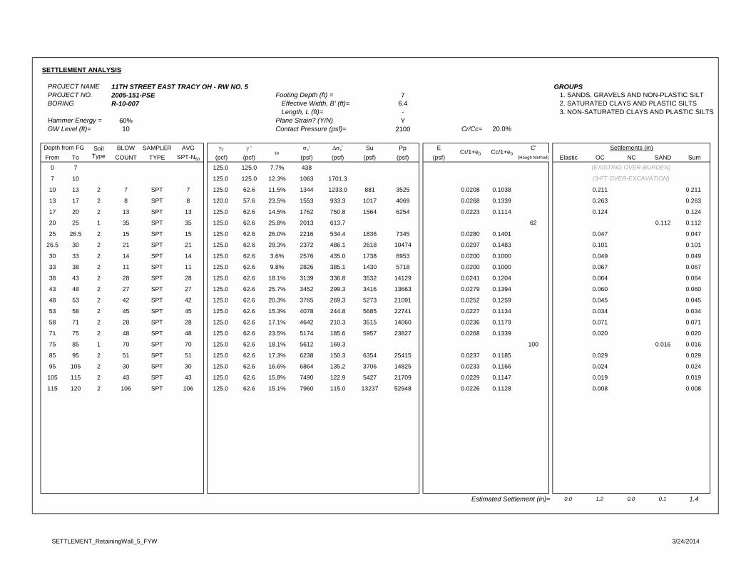
SETTLEMENT ANALYSIS
PROJECT NAME 11TH STREET EAST TRACY OH - RW NO. 5 GROUPSPROJECT NO. 2005-151-PSE Footing Depth (ft) = 7 1. SANDS, GRAVELS AND NON-PLASTIC SILT BORING R-10-007 Effective Width, B' (ft)= 6.4 2. SATURATED CLAYS AND PLASTIC SILTS
Length, L (ft)= - 3. NON-SATURATED CLAYS AND PLASTIC SILTSHammer Energy = 60% Plane Strain? (Y/N) YGW Level (ft)= 10 Contact Pressure (psf)= 2100 Cr/Cc= 20.0%
BLOW SAMPLER AVG ' v' v' Su Pp E C'From To COUNT TYPE SPT-N60 (pcf) (pcf) (psf) (psf) (psf) (psf) (psf) (Hough Method) Elastic OC NC SAND Sum
0 7 125.0 125.0 7.7% 438
7 10 125.0 125.0 12.3% 1063 1701.3
10 13 2 7 SPT 7 125.0 62.6 11.5% 1344 1233.0 881 3525 0.0208 0.1038 0.211 0.211
13 17 2 8 SPT 8 120.0 57.6 23.5% 1553 933.3 1017 4069 0.0268 0.1339 0.263 0.263
17 20 2 13 SPT 13 125.0 62.6 14.5% 1762 750.8 1564 6254 0.0223 0.1114 0.124 0.124
20 25 1 35 SPT 35 125.0 62.6 25.8% 2013 613.7 62 0.112 0.112
25 26.5 2 15 SPT 15 125.0 62.6 26.0% 2216 534.4 1836 7345 0.0280 0.1401 0.047 0.047
26.5 30 2 21 SPT 21 125.0 62.6 29.3% 2372 486.1 2618 10474 0.0297 0.1483 0.101 0.101
30 33 2 14 SPT 14 125.0 62.6 3.6% 2576 435.0 1738 6953 0.0200 0.1000 0.049 0.049
33 38 2 11 SPT 11 125.0 62.6 9.8% 2826 385.1 1430 5718 0.0200 0.1000 0.067 0.067
38 43 2 28 SPT 28 125.0 62.6 18.1% 3139 336.8 3532 14129 0.0241 0.1204 0.064 0.064
43 48 2 27 SPT 27 125.0 62.6 25.7% 3452 299.3 3416 13663 0.0279 0.1394 0.060 0.060
48 53 2 42 SPT 42 125.0 62.6 20.3% 3765 269.3 5273 21091 0.0252 0.1259 0.045 0.045
53 58 2 45 SPT 45 125.0 62.6 15.3% 4078 244.8 5685 22741 0.0227 0.1134 0.034 0.034
58 71 2 28 SPT 28 125.0 62.6 17.1% 4642 210.3 3515 14060 0.0236 0.1179 0.071 0.071
71 75 2 48 SPT 48 125.0 62.6 23.5% 5174 185.6 5957 23827 0.0268 0.1339 0.020 0.020
75 85 1 70 SPT 70 125.0 62.6 18.1% 5612 169.3 100 0.016 0.016
85 95 2 51 SPT 51 125.0 62.6 17.3% 6238 150.3 6354 25415 0.0237 0.1185 0.029 0.029
95 105 2 30 SPT 30 125.0 62.6 16.6% 6864 135.2 3706 14825 0.0233 0.1166 0.024 0.024
105 115 2 43 SPT 43 125.0 62.6 15.8% 7490 122.9 5427 21709 0.0229 0.1147 0.019 0.019
115 120 2 106 SPT 106 125.0 62.6 15.1% 7960 115.0 13237 52948 0.0226 0.1128 0.008 0.008
Estimated Settlement (in)= 0.0 1.2 0.0 0.1 1.4
Depth from FG SoilType Cr/1+e0 Cc/1+e0
Settlements (in)
(EXISTING OVER-BURDEN)
(3-FT OVER-EXCAVATION)
SETTLEMENT_RetainingWall_5_FYW 3/24/2014

PAVEMENT CALCULATION
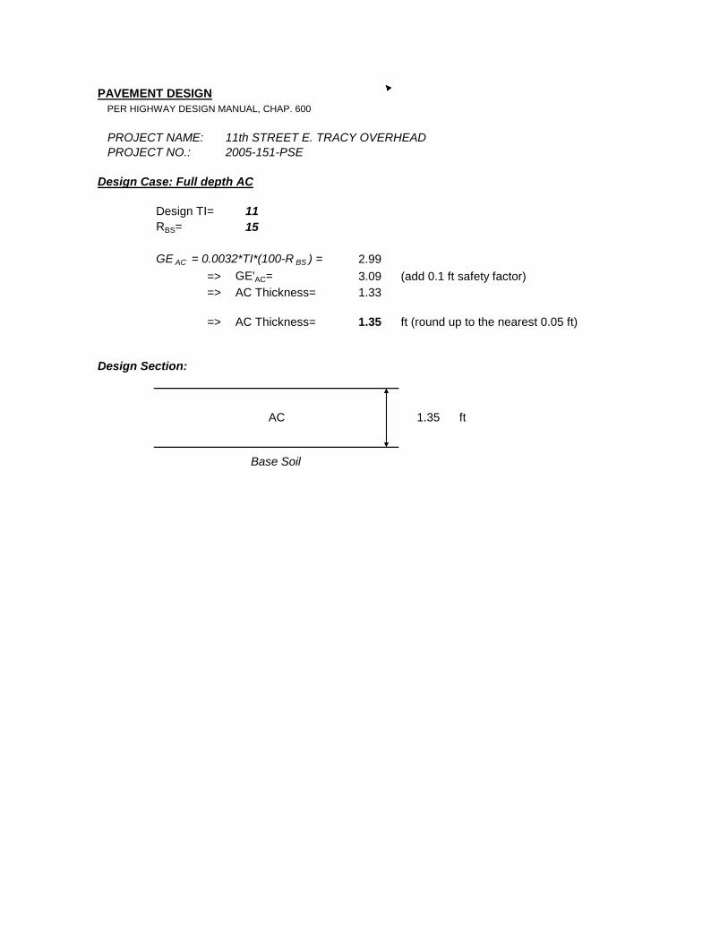
PAVEMENT DESIGNPER HIGHWAY DESIGN MANUAL, CHAP. 600
PROJECT NAME: 11th STREET E. TRACY OVERHEADPROJECT NO.: 2005-151-PSE
Design Case: Full depth AC
Design TI= 11RBS= 15
GE AC = 0.0032*TI*(100-R BS ) = 2.99=> GE'AC= 3.09 (add 0.1 ft safety factor)=> AC Thickness= 1.33
=> AC Thickness= 1.35 ft (round up to the nearest 0.05 ft)
Design Section:
1.35 ft
Base Soil
AC
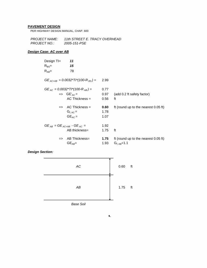
PAVEMENT DESIGNPER HIGHWAY DESIGN MANUAL, CHAP. 600
PROJECT NAME: 11th STREET E. TRACY OVERHEADPROJECT NO.: 2005-151-PSE
Design Case: AC over AB
Design TI= 11RBS= 15RAB= 78
GE AC+AB = 0.0032*TI*(100-R BS ) = 2.99
GE AC = 0.0032*TI*(100-R AB ) = 0.77=> GE'AC = 0.97 (add 0.2 ft safety factor)
AC Thickness = 0.56 ft
=> AC Thickness = 0.60 ft (round up to the nearest 0.05 ft)Gf, AC = 1.78GEAC = 1.07
GE AB = GE AC+AB - GE AC = 1.92AB thickness= 1.75 ft
=> AB Thickness= 1.75 ft (round up to the nearest 0.05 ft)GEAB= 1.93 Gf, AB=1.1
Design Section:
ft
ft
AC
Base Soil
AB
0.60
1.75
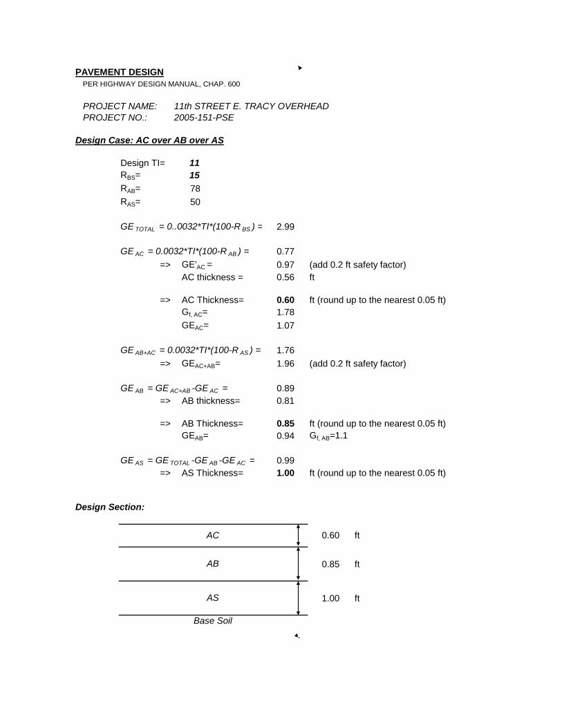
PAVEMENT DESIGNPER HIGHWAY DESIGN MANUAL, CHAP. 600
PROJECT NAME: 11th STREET E. TRACY OVERHEADPROJECT NO.: 2005-151-PSE
Design Case: AC over AB over AS
Design TI= 11RBS= 15RAB= 78RAS= 50
GE TOTAL = 0..0032*TI*(100-R BS ) = 2.99
GE AC = 0.0032*TI*(100-R AB ) = 0.77=> GE'AC = 0.97 (add 0.2 ft safety factor)
AC thickness = 0.56 ft
=> AC Thickness= 0.60 ft (round up to the nearest 0.05 ft)Gf, AC= 1.78GEAC= 1.07
GE AB+AC = 0.0032*TI*(100-R AS ) = 1.76=> GEAC+AB= 1.96 (add 0.2 ft safety factor)
GE AB = GE AC+AB -GE AC = 0.89=> AB thickness= 0.81
=> AB Thickness= 0.85 ft (round up to the nearest 0.05 ft)GEAB= 0.94 Gf, AB=1.1
GE AS = GE TOTAL -GE AB -GE AC = 0.99=> AS Thickness= 1.00 ft (round up to the nearest 0.05 ft)
Design Section:
0.85 ft
1.00 ft
Base Soil
ftAC 0.60
AS
AB