foundation characteristics of the upper carboniferous rocks
TRANSCRIPT

Foundation characteristics of the Upper Carboniferous rocks
A L A N C O T T O N M E I G H
SUMMARY
The paper is primarily concerned with the bearing capacity and settlement characteristics. Mining subsidence is not considered. The location of 'exposed" Upper Carboniferous rocks is briefly outlined in relation to urban and industrial areas, and depths to rockhead are discussed.
The characteristic cyclic pattern of deposition of the Coal Measure rocks is described, and descriptions of the principal rock types, and some overlying soils are given. In the Coal Measure rocks the upper surface is usually weathered. Over mudstones there is typically 10 ft or so of material weathered to a clay, followed by less weathered rock. Over sandstones the fully weathered zone is thinner and usually consists of clayey sand containing weathered sandstone fragments. Depth of weathering may be locally increased near faults and where dips are steep.
Exploration is often by soft ground boring methods in the overlying soils followed by diamond drilling in rock. Nx-size core barrels are the minimum size which can be expected to give 100 per cent core recovery, and on important jobs it is recommended that a larger size should be used. Drill core required for laboratory testing must be protected against drying-out and against frost action. The value of trial pits is emphasized.
Some laboratory test values of compression strength and deformation modulus are given in the paper and the limitations of laboratory testing are discussed.
Standard Penetration Tests have been used in the Coal Measure shales and mudstones to give a rough guide to rock strength. A tentative correlation between S.P.T. values and rock description is given. Other in situ testing techniques are the Menard Pressuremeter Test, the Plate Loading Test and loading tests on piles. For plate loading tests in pits and at the base of piles it is essential that the material below test level is undisturbed. Seepage forces from ground water must be avoided since they can cause rapid deterioration. The usual pile loading test involves load application at the head of the pile, but valuable information can be obtained from tests in which end bearing resistance is measured separately from side shear within the 'rock socket'.
Data is given for three sites where plate loading tests were carried out, together with laboratory testing. From this data and from laboratory test data presented elsewhere in the paper, characteristic values of compression strength and deformation modulus have been chosen.
It has been customary to assign allowable bearing capacities to Upper Carboniferous rocks on the basis of visual inspection; typical values are quoted. For a calculation of allowable bearing pressure recent practice is to use the results of in situ loading tests. Unfortunately there do not appear to be any published data concerning the behaviour of full-scale foundations.
It is suggested that for the Upper Carboniferous rocks, bored cast-in situ piles are generally preferable to driven piles. Ranges of working loads, and corresponding penetrations, are discussed and comments are made on pile spacings. Pile loading test data presented for three sites appear to support these empirical criteria.
A more rational estimation of pile bearing capacity would involve considerations of end bearing capacity and of side shear within the rock socket. This is difficult since side shear between concrete and rock depends not only on rock strength and deformation character- istics, but also on the response of the rock to the pile boring processes. Further development must depend on correlation of performance data with careful and detailed description of the rocks involved.
Q. Jl Engng Geol. Vol. 1, 1968, pp. 87-113, pls. 7-8, 10 figs. Printed in Great Britain.

A. C. Meigh
1. Introduct ion
IN TrIE broad sense, the term 'foundation characteristics' covers the response of the ground to superimposed loading by buildings, industrial structures, or other works, to seepage forces by impounded water and to shear stresses set up by cuttings and by embankments and other loads placed on sloping ground. However, the paper is primarily concerned with the bearing capacity and settlement characteristics of the more common Upper Carboniferous rocks, and it sets out to examine the characteristics of those rocks which determine their response to foundation loads, including piled foundations, and to outline the methods which are used to determine those characteristics. This immediately raises the question of mining subsidence, since in many cases this may dominate foundation considerations, but this is outside the scope of this paper.
Another important topic, having a bearing on new motorway construction over Upper Carboniferous rocks, is slope stability, but this aspect is also not treated in the present paper. Considerations of permeability and seepage are also omitted.
The paper is in three parts, w 2 covering the subject in general terms and w 3 giving data from particular sites. In w the data is reviewed and the paper summarized.
2. General
(A) TaE ROC :S It is hardly necessary to describe the location at which the Coal Measure rocks occur since these are in the exposed portions of the coalfields and the positions of these are well known. It is however, necessary to consider the coincidence of those rocks with areas of urban and industrial development and to consider the extent to which the rocks in these areas are covered by drift. In the Glasgow area for example, the Coal Measure rocks of the Central Coalfield of Scotland are to a great extent covered with an appreciable thickness of glacial drift, together with recent alluvium, so that at engineering sites they have frequently been found at 80 to 100 ft below ground level, often at greater depths than this and occasionally at shallower. They do not therefore enter into the majority of foundation problems and only become of importance when very heavy loads are to be carried without significant settlement. Appreciable thicknesses of Glacial Drift are also found in the Newcastle-on-Tyne area and in Glamorgan, South Wales in the valley and coastal areas where it is often overlain by Dune sands and recent alluvium. In the Lancashire Coalfield, including the industrial areas of Manchester, Bolton and Burnley, moderately thick Glacial Drift is found, typically 20-40 ft thick.
In the Yorkshire-Nottinghamshire Coalfield on the other hand, in the exposed portion of the Coalfield running from Leeds south through Sheffield and Doncaster down to Nottingham and coinciding with heavy industrial areas, the Coal Measure rocks are generally close to the surface although there is a certain amount of recent alluvium in the river valleys. In some places also there is made ground, typically 10-20 ft thick, but sometimes up to 50 ft, consisting either of waste from collieries or open-cast operations or general filling in industrial areas, including filling from levelling of sites. In this area then, many foundations can be placed on footings or rafts at comparatively shallow depths or on piles of not very great length.
Immediately to the west of the Yorkshire-Nottinghamshire Coalfield the Millstone Grit, the lower part of the Upper Carboniferous rocks, forms the flank of the Pennines
88

Foundation characteristics of the Upper Carboniferous rocks
and has become of importance now that east to west motorways for this area are under consideration.
Rock types In the Coal Measures there is a characteristic rhythmic pattern of deposition, usually
one cycle consisting of sandstone grading downwards into shale or mudstone, followed by coal with seat-earth at its base. Sometimes the cycle will include, above the coal, a thin marine band, consisting of argillaceous material deposited in sea water. Typically one cycle is 30-50 ft thick. There are, of course, considerable variations in the pattern; the thickness of different members may vary greatly and some of them may be absent (P1. 7).
The sandstones are sometimes coarse grained but mainly fine or fine-to-medium grained. They are mainly hard, and yellow or light-brown in colour due to iron-staining, but when fresh in depth are often grey in colour. Many of the sandstones show marked current bedding. Their thickness can show wide lateral variations. Many are thick-bedded and massive; some are well laminated (flagstones). They also include quartzites, notably in the Lower Coal Series in South Wales and Bristol.
Fine grained sandstone often grades into siltstone. The siltstones are frequently pale grey in colour, and less prone to iron-staining than the sandstones. They are generally hard and are often massive but jointed.
The siltstones grade into very silty mudstones, generally pale to medium grey in colour and hard or medium-hard, and are often laminated. In some places rocks are found with siltstone and very silty mudstone laminations in equal proportions.
Silty mudstones, mainly grey in colour and of medium hardness, have a lower but still important silt content. Slightly silty mudstones are usually dark grey in colour and of medium hardness and often do not possess any distinct bedding or lamination. They are very susceptible to change in moisture content on exposure, softening and becoming 'clayey' when wet and breaking up into shaley fragments on drying (P1. 8). These properties become more noticeable with decreasing silt content.
Seat-earths, under the coal seams, are often modified mudstones and represent a fossil soil. Sometimes however, seat-earths are arenaceous. A distinctive feature is the presence of rootlets. Argillaceous seat-earths in the fresh state have properties close to those of a hard clay and some have marked swelling properties. Beds of fireclay, not in association with coal seams, are often found, particularly in Scotland and can be up to 20 ft thick. These are very similar in nature to the argillaceous seat-earths referred to above.
Coal seams only form a very small proportion of the Coal Measure rocks. However, they can present problems in that they form aquifers and often deteriorate severely on exposure.
Weathering and faulting An important feature of the Upper Carboniferous rocks, for foundation purposes,
is the weathered zone which occurs at the upper surface. The nature and thickness of the weathered zone depends on the nature of the rock. Where sandstones occur at the upper surface, the fully weathered zone will consist of clayey sands with fragments of weathered sandstone and will usually be only a few feet thick. The transition into unweathered sandstone is usually quite rapid. Over mudstones, on the other hand, there is usually
3~o 89

A. C. Meigh
a mantle of material which has been weathered down to a clay, with no evidence of the original rock structure. This fully weathered zone is often about 10-15 ft thick and may be followed by a gradual transition through less severely weathered material into un- weathered bedrock.
Where the original rock included thin alternating bands of sandstone (or siltstone) and mudstone, the weathered zone may include bands of more resistant and hence less weathered rock, so that stiff clay, from decomposed mudstone, may underlie relatively unweathered sandstone. In some instances siltstones may show similar deterioration in depth, their permeability allowing extensive penetration of ground water.
In much of the Coal Measures, dips are gentle. However, the Coal Measure rocks are considerably faulted with many of the Coalfields having extensive boundary faults. Close to the faults dips are often steeper and the depth of weathering may be locally increased.
(B) EXPLORATION METHODS
Exploration of the Upper Carboniferous rocks for foundation purposes is usually carried out by soft ground boring methods which are used to penetrate the overburden and the very weathered zone at the top of the rock, and this is usually supplemented by diamond drilling to recover cores of the underlying rock. An important factor to be considered in diamond drilling is the size of core barrel since this will largely determine the percentage core recovery. Complete core recovery (100 per ten0 is desirable because the core, if lost, will be from weaker materials which may well be important in the foundation problem. Experience has shown that small size cores, e.g. EX, AX and BX will not generally produce 100 per cent core recovery; frequently they give recovery in the range 50 to 70 per cent, whereas Nx-size core barrels (2~-in diameter core) will frequently give core recovery close to 100 per cent. However, this requires a good driller, equipment in good condition, free from vibration, appropriate choice of diamond bits, and the use of swivel- type double-tube core barrels, and even under these conditions cannot always be relied on to give 100 per cent recovery. For important jobs therefore it is prudent to use a larger diameter core barrel, and one which has proved to be particularly useful is 131 mm (4-in diameter core). There would appear to be little advantage in adopting a larger core size than this.
It is essential that drill cores which are to be used to provide laboratory test specimens are preserved at their natural moisture content and are protected from frost action. This can be done by wrapping them in polythene sheeting, carefully sealed. Where frost is to be expected, cores should be kept in heated storage. In order to avoid the necessity of wrapping all the core, it is advantageous to have a geologist on site who will select core for wrapping immediately it is obtained. He can then log the remaining core before there is any possibility of serious deterioration.
Another method of exploration which can often be useful in conjunction with boring and drilling, particularly where the cover is thin, is the use of trial pits. These can often be put down cheaply and quickly using modern mechanical excavating equipment and they have a great advantage over boring and drilling in that they enable the engineer or geologist to inspect the material in situ and to assess the nature of the bedding and j ointing and other structural features of the rocks. At the same time they give access for plate loading tests and for obtaining block samples. This possibility of examination and handling of materials in situ is one which should be emphasized since it gives the
90

Foundation characteristics of the Upper Carboniferous rocks
experienced engineer or geologist valuable insight into the particular site, enabling him to relate it to other sites. It also provides the less experienced with an opportunity to develop their feeling for and understanding of the nature of foundation materials.
( c ) LABORATORY TESTING
Laboratory testing on specimens obtained from diamond drill cores or from blocks cut in trial pits is frequently used to determine the compressive strength and deformation modulus 1 of the foundation rocks. However, considerable caution is required in using the results of such tests since in the stronger rocks small specimens do not include the effects of jointing and bedding planes. Moreover, in the weaker rocks the process of coring and preparation of specimens is such that it is the better specimens which are tested and hence the results again will give too optimistic a picture of the rock character- istics. On the other hand if cores of weak material should be obtained they may have been weakened further by the action of drilling water and by stresses imposed in drilling and sample preparation.
An example of very high strengths measured on laboratory specimens is the data given by Hobbs (1964). His average crushing strength values for specimens 2 in x 1 in diameter and 1�89 in • 1 in diameter are given in Table 1 below. These were tests on materials obtained at depth from mine workings. It appears that the specimens were air dried in the labora- tories for 14 days prior to testing.
TABLE 1 : Laboratory compression test results (after Hobbs)
Rock type Description Crushing strength
(average) lb/sq in tons/sq ft
Pennant sandstone
Ormonde sandstone
Kirkby siltstone Oxcroft mudstone
Massive, finely laminated, 24 500 1 600 fine-grained sandstone
Massive, medium grained 9 000 570 sandstone
Muddy siltstone 13 400 860 Finely spaced bedding planes 2 200 140
at right angles to joints which were �88 in apart
Hobbs refers to the difficulty of coring specimens in the laboratory from rough blocks, and mentions specimen 'yield rates' of 95 per cent for sandstones, but only 10-50 per cent for mudstones.
There is very little published data on laboratory values of deformation modulus. Phillips (1930) gives values obtained from flexural tests on intact specimens. These show an average value for three fine-grained sandstones of E = 8.3 x 10⁶ lb/sq in (530 000 tons/sq ft), and for three shales E = 5.4 x 10⁶ lb/sq in (350 000 tons/sq ft).
Again these were tests on air-dried specimens, not at natural moisture content. It is vital that tests on rock specimens are carried out at the natural moisture content. Very
1 Deformation modulus (more fully 'modulus of linear deformation') is analogous to Young's Modulus, but covers behaviour which is not strictly elastic. It is used in this report more often in a general sense, but where used in a particular sense this has been noted.
91

A. C. Meigh
significant increases in strength are shown on dried-out specimens, particularly in argillaceous rocks.
In the weathered zone at the top of the rock, open-drive samples are sometimes taken and laboratory compression tests carried out on the specimens so obtained. However, these are frequently disturbed in the sampling processes and where the shear strength is greater than about 11 to 2 tons/sq ft, the laboratory test values can often be only a small fraction of the in situ strength.
(D) IN SITU TESTING
In the light of the difficulties of obtaining representative undisturbed specimens for laboratory testing, it can be seen that in situ testing is of great importance in assessing strength and deformation characteristics of soft rocks. Such tests cover the adoption of the Standard Penetration Test as a rough guide to rock strength, the Menard Pressure- meter Test, and Vertical Loading Tests on plates of various sizes, usually carried out in trial pits, and loading tests on piles.
The Standard Penetration Test This was originally developed for assessing the relative density of granular soils and
in the late 1950's its use was extended to soft rocks, where these were explored using standard soft ground boring techniques as used in clays and sands. A study of Standard Penetration Test values in soft rocks, by the author 's colleagues, J. C. Dixon and R. D. Carter, in 1960, was primarily related to Chalk, Bunter Sandstone and Keuper Marl. This work has also been extended to cover Coal Measure shales and mudstones, and a tentative correlation between a visual description of rock properties and S.P.T. values is given in the table below:
Description Visual identification Range of N values
(N = blows/ft)*
Weak
Medium strong
Strong
Weathered. Can be deformed by heavy pressure with the fingers.
Often slightly weathered. Can be deeply scored with a knife blade, and broken by hand or split with a knife blade.
Unweathered. Can be scratched with a knife, but can only be broken with a hammer.
0-100
100-250
Greater than 250
* In practice, high values of N will be extrapolated values, based on blow count for a penetration less than one foot.
The Pressuremeter Test The Menard Pressuremeter Test to determine yield strength and deformation modulus
has recently been applied to soft rocks and its use in Coal Measure rocks has been des- cribed by Meigh & Greenland (1965).
92

Foundation characteristics of the Upper Carboniferous rocks
The Vertical Loading Test This is often referred to as a plate loading test. It is simple, and although somewhat
expensive, probably provides the most valuable information by which the bearing capacity and settlement characteristics of the rocks at any particular site can be assessed.
It is, of course, necessary to ensure that the plate rests on material which is undisturbed. This can be difficult where testing is required below ground water level, since even if the pit is dry, or can be kept dry, seepage forces acting on the rock immediately below the base of the pit may cause rapid deterioration. In some cases it may be necessary to install wells around the pit and lower the ground water level before the pit is advanced below the water table. In some rocks stress relief may cause slight heave at the base of a pit or pile boring. The effect can be minimized by testing as rapidly as possible after 'bottoming- up', but cannot be entirely avoided. In such cases a plate loading test may give a con- servative measure of deformation modulus.
In the Upper Carboniferous rocks care should be taken to choose test levels which will give an overall picture of the various classes of rock involved within the zone which will be stressed by the foundation. Typical results of plate loading tests are given in w 3 of this paper.
Loading tests on piles In the standard procedure it is considered sufficient to apply the load, in stages, at the
head of the pile by jacking against kentledge or against reaction from adjacent piles or from rock anchorages. Examples of such pile loading tests are given in w 3. However, in order to understand the mechanism of pile action under load, it is advantageous to measure separately end bearing capacity and side shear for that part of the pile embedded in the foundation rock. Some examples of this procedure are given by Thorburn (1966).
(E) FOUNDATIONS
In discussing generally the bearing capacity and settlement characteristics of the Upper Carboniferous rocks, reference must again be made to mining subsidence, since in some cases this may be an overriding consideration when calculating settlements, and shallow mine working may affect bearing capacity considerations.
Shallow foundations Civil Engineering Code of Practice No. 4 Foundations--published in 1954 (CP4)
gives the following values for maximum safe bearing capacity for horizontal foundations at 2 ft depth below ground surface under vertical static loading.
Hard shales, mudstones and soft sandstones Clay shales Thinly bedded sandstones 1 Heavily shattered rocks j
20 tons/sq ft 10 tons/sq ft To be assessed
after inspection
This is of rather limited value in relation to the wide range of rock conditions found in the Upper Carboniferous rocks. Until recently it has been customary to assign safe bearing pressures to Upper Carboniferous rocks on the basis of visual inspection or examination of cores. For foundation levels within the weathered zone, allowable bearing pressures of 2 or 3 tons/sq ft have been considered to be satisfactory and in the relatively
93

A. C. Meigh
unweathered rock bearing pressures of 5 tons/sq ft have frequently been used in the argillaceous rocks, increasing to perhaps 10 tons/sq ft in sound siltstones and sandstones, and in some cases to as much as 20 tons/sq ft in thick layers of massive sandstone.
For a calculation of allowable bearing pressure, recent practice has been to use the results of in situ testing. However, this involves some assumptions concerning the scale factor between small in situ tests and larger foundations. The assumption of elasticity, giving a linear relationship between settlement and footing diameter for a given loading intensity, is frequently used making due allowance for variation of deformation modulus within the zone of influence of the loading which extends deeper with increasing footing size. This assumption may well be too conservative, but until there is a substantial body of data on the performance of loaded foundations, it is difficult to see how the situation can be improved. Unfortunately a recent intensive search of the technical literature has not revealed a single case history.
Where argillaceous rocks are exposed at foundation level, particularly mudstones of low silt and high clay content, care must be taken to blind the rock immediately following excavation to formation level in order to prevent deterioration of the rock.
Piled foundations Both driven piles and bored cast-in situ piles have been used to carry foundation loads
down into the Upper Carboniferous rocks. A driven pile has disadvantages, in that it tends to cause serious shattering and it may hold up on a thin sandstone layer underlain by severely weathered shale or mudstone. With driven piles at close centres, heave is likely. On the other hand, a bored cast-in situ pile can more readily penetrate the weathered zone. Furthermore, the materials passed through can be identified and in some cases its base can be inspected to ensure that it is in sound bedrock. In this connection it should be emphasized that the site investigation should be sufficiently detailed to give adequate knowledge of the rocks below the toes of the piles.
Very often the allowable loading can be equivalent to the Code of Practice (CP4) maximum allowable stress in the concrete, namely 750 lb/sq in or 48 tons/sq ft, of pile cross-sectional area. The penetration necessary to develop this capacity will vary with the rock conditions, as indicated by the site investigation, and in some cases as modified by the conditions found when constructing the piles. Where the foundation material consists of a sufficiently thick layer of sound sandstone, a penetration of about one pile diameter is usually sufficient and where the sandstone is very hard this can be reduced to about half a pile diameter. In shales and mudstones penetration of three or four pile diameters into sound bedrock will be necessary. In each case, pile loading tests should be carried out, prior to the main piling work, to confirm the chosen loadings and penetrations. In some cases, where the number of piles involved in the construction may be insufficient to justify the expense of pile loading tests, it will be preferable to use a more conservative loading, without confirmation by pile tests.
There may be sites where the zone of weathering may persist to appreciable depths and it may be desired to terminate piles in material which is outside the category of sound unweathered bedrock. In such cases it is probable that loadings of about 30 tons/sq ft of pile cross-sectional area can be used, again subject to confirmation by pile loading tests. Some reduction may also be necessary where there are steeply dipping strata, or mudstones which are found to deteriorate rapidly during boring. In some areas it has been found that mudstones of low silt and high clay content are susceptible in this way.
94

Foundation Characteristics of the Upper Carboniferous rocks
Some caution is necessary when piles are required at close centres. CP4 recommends a spacing of not less than two pile widths for end-bearing piles, and not less than one pile perimeter for friction piles. It would be prudent to regard a bored pile founded in the Upper Carboniferous rocks as a friction pile in this context. Furthermore, if the strati- fication is such that significant disturbance might be expected, it is suggested that some- what wider spacing should be used, or alternatively working loads reduced.
It is obviously desirable to place the estimation of pile bearing capacity on a more rational basis than the purely empirical approach suggested above. This would require separate consideration of the contribution of end-bearing and of side shear for that part of the pile embedded in the rock, (referred to by Thorburn, 1966, as the 'rock socket'). End-bearing capacity can often be assessed from carefully executed plate loading tests. It is unlikely that laboratory compression test results alone will ever serve this purpose, although they can give useful information to aid judgement and to extend the information from plate loading tests.
The contribution of side shear between concrete and rock in the rock socket presents greater difficulties. It is a function not only of the strength and deformation characteristics of the rock mass, which will almost certainly vary over the depth of the socket, but also of the response of the rocks involved to the pile boring processes. It seems likely therefore that any improvement in our knowledge of the behaviour must come from careful observation and from correlation of pile performance with detailed description of the rocks involved, including all structural features. This could also include laboratory test results but regarding them as providing index properties rather than parameters to be used in calculation. In addition, loading tests which measure separately end-bearing and side shear should be carried out whenever possible.
Sulphates On many sites where Coal Measure rocks occur, the ground water is found to have a
sufficiently high sulphate content to require special measures to avoid attack on the concrete. Crutchlow (1966) has indicated that particularly high sulphate concentrations occur in the vicinity of colliery tips.
3. Particular Sites (A) WAKEFIELD, YORKS
In the Wakefield area a site investigation with more than 600 boreholes was carried out along part of the proposed Sheffield-Leeds Motorway between Dodworth near Barnsley in the south and Stourton near Leeds in the north. The drilling was almost entirely in 131 mm and 101 mm sizes (4 in and 28z in core) and in about 11 000 ft of drilling core recovery was over 95 per cent, generally 100 per cent, except for a few short runs. The route lies on the outcrop of Middle Coal Measure rocks. Sand and gravel and alluvial deposits of recent and possibly late post-glacial age overlie the rock in the present river valleys. Elsewhere the overburden is thin consisting mainly of in situ decomposed rock products. The boreholes confirmed the typical Coal Measures cyclic type of sedimentation consisting in general of sandstones or siltstones separated by variably silty mudstone with coal seams at their base. However, it was often found that cycles were incomplete, the coal seams being closer together and sandstone strata being absent. A selection of simplified borehole logs is given in P1. 7.
95

A. C. Meigh
Since the ground conditions along this route are typical of most of the exposed portion of the Yorkshire-Nottinghamshire Coalfield, it may be of interest to describe the main rock types and the overlying soils in some detail, and this is done in Appendix A, which also includes a summary of values of index properties, compressibilities, and compression strengths obtained from laboratory tests.
Because of the effects of sample disturbance on strength measurements, it was decided to carry out a programme of in situ testing in order to determine the levels and bearing pressures for bridge foundations. The testing consisted of pressuremeter tests in drillholes and plate loading tests in trial pits, using 12-in square plates. The pressuremeter tests have been reported elsewhere (Meigh & Greenland 1965).
For the plate loading tests, the load was applied vertically at the bottom of the pit by hydraulic jacking against steel reaction beams loaded by Kentledge. The jack base rested directly on the steel loading plate which was bedded with a grout veneer. A ball and socket joint was interposed between the load cell and the reaction beam. The load was measured by calibrated pressure gauge and by an electrical strain gauge load cell. The deflexion was measured as the arithmetic mean of four dial gauges reading to 0.001 in, these being attached to a datum beam firmly anchored outside the effective area of deflection and recording movement of the loading plate at points equally spaced around its circumference.
Up to 10 tons load the load was applied in increments of 1 ton and after 10 tons in increments of approximately 2 tons. The dial gauge readings were recorded after each loading increment and also at intervals of one minute until the rate of deflexion fell below 1/1 000th in/min.
The load-settlement curves from the plate loading tests are given in Fig. 1. From these curves, values of deformation modulus were calculated from the load settlement curves using the relationship:
S = - ( 1 - V 2)
where S = deflection, E = deformation modulus, V = Poisson's ratio, q -- loading intensity and r = radius of plate (equivalent radius in the case of the square plate). The resulting values of the modulus are given in Table 2.
It is interesting to note the fairly wide range of behaviour covered by these tests. Test 3A on very weathered silty mudstone at shallow depth gave a failure condition at a loading of about 7�89 tons/sq ft, equivalent to a stiff clay with a shear strength of about 2 500 lb/sq ft. Test 38, on similar, but less weathered material, at the same location but 3 ft 6 in deeper, also reached failure, but at more than twice the equivalent shear strength. At the other limit, tests 1 and 6, on relatively unweathered mudstone and siltstone respec- tively, showed only small settlements at maximum loading with E values around 2 000 tons/sq ft.
On the basis of these test results, together with the pressuremeter test results, it was possible to specify allowable bearing pressures for the various bridge foundations generally between 5 and 10 tons/sq ft.
(B) CUMBERNAULD, DUNBARTONSHIRE
An investigation was carried out at Cumbernauld to determine the foundation conditions for a new town centre development. The site is near the crest of a broad hill some 450 ft
96

m 1. 0 r" u E ._
s
IE Ill .,..1
~ 1 . 4 w
Foundation characteristics of the Upper Carboniferous rocks
LOADING INTENSITY~ tons/sq , ft. O 10 20 30 .40
0
0.2 i l /
0.4 ~ .....
l \
.,,
~, S ILTSTONE VERY WEATHERED SILTY MUDSTONE WEATHERED
1 �9 6 SILTY MUDSTONE WEATHERED SANDSTONE
5 11 ft.O in. WEATHERED 1-8 SANDSTONE 6 7 ft.O in SILTSTONE
240
2 .2
. 2 " 4 I
FIG. 1. Plate loading test results, Wakefield (12-in square plates).
WABLE 2" WakefieM plate loading tests
Site Level of test
(It below G.L.)
Material
E, Secant modulus (tons/sq ft)
Loading range Loading range 0--5 tons/sq ft 0--10 tons/sq ft
1. Pog Well Lane
2. Barugh Green 3. Great Cliff A.
B .
4. Holling Hall Lane
5. Horbury Road
6. Queen's Drive
13 ft 9in
11 f t 3 i n 8 ft 0 in
11 ft 6in
6ft 9 in
11 ft 0in
7ft 0 in
Medium strong mudstone 2 300 1 770
Weak siltstone 680 470 Very weak very
weathered silty mudstone 77 Weak, weathered
silty mudstone 205 170 Very weak, clayey
weathered sandstone 440 340 Weathered sandstone
with bands of soft clayey sandstone 1 400 650
Medium strong siltstone 2 100 1 900
97

A. C. Meigh
above OD, the ground surface sloping gently down in a southerly direction. The superficial material is a thin layer of stiff sandy Boulder Clay but this had been removed over most of the area investigated. Seven Nx size diamond drillholes were put down and core recovery was generally 100 per cent, although in one drillhole only 80-90 per cent was obtained in a shale horizon. In addition, three pits were put down and in two of these plate loading tests were carried out.
The near surface rocks of the site consist of sandstones and shales of Lower Carboni- ferous age. z The downward succession revealed by the boreholes and pits was alternating shale and sandstone finely interbedded, sandy shale and shale. Within these broad stratigraphical formations based on lithology there is lateral change, in particular the local development of larger sandstone or shale beds near the top of the closely inter- bedded formation. There is a gentle dip throughout the area of the site of approximately 2�89 ~ towards the east. No evidence of faulting was encountered. A geological section across part of the site is shown on Fig. 2.
B.H.$ (4 6') B.H g (+ 28') BH.3 (- |2')
SST. Bed F INELY INTERBEDDED SHALE AND SANDSTONE ~ Shole 450 A.O.D SS~ Bed
BH.7 (d)
I BH.I (-80') TP3 (-52') B.H.2 (+S6')
~ m
B.H.4 (- 43')
I
BOULDER CLAY
THICKER SANDSTONE BEDS
[ ~ FINELY INTERBEDDED SHALE AND SANDSTONE
[ ] CALCAREOUS SANDSTONE BEDS ( M a r k e r bed only s h o w n on s e c t i o n )
] ANDY SHALE
~ ] SHALE
- - 2 - - APPROX. GROUND WATER Ls
20 10 0 h , .H .H
NOTE: D i m e n s i o n s i n b r a c k e t s d e n o t e a c t u a l d i s t a n c e o f b o r e h o l e f r o m l i n e o f s e c t i o n . + Nor th of l i n e o f s e c t i o n - S o u t h o f l l n e o f s e c t i o n
20 40 60 80 100 FT. I I I I I
FIG. 2. Geological section, Cumbernauld.
z The rocks are of the Upper Limestone Group of the Carboniferous Limestone Series. They are not therefore Upper Carboniferous rocks. However they are very similar in lithology to the immediately overlying Millstone Grit series of the Upper Carboniferous.
98

Foundation character&tics of the Upper Carboniferous rocks
The rock in the pits was generally found to be fresh with only very slight evidence of weathering in some joints. The joints in the shale are fairly tight but those in the sandstone tend to be more open. The rock types were classified as follows:
Class I, Sandstone: Finely banded grey and partly calcareous, fine grained. Class II, Finely Interbedded Sandstone and Sandy Shale: Sandstone as Class I. Very thin
bedding in places; sandstone occasionally calcareous. Class III, Sandy Shale: Class IV, Shale: Dark grey to black with sparsely scattered calcareous nodules.
From observations of the water levels during the drilling and pit sinking, it appears that the water-table at the time of the investigation was at levels varying between 444 ft and 448 ft above OD which is some 8 ft below ground level. The water is contained in the joints and bedding planes of the rock, greater quantities existing in the sandstone beds than in the shales, due to slightly more open jointing. One particular joint in Test Pit 3, in calcareous sandstone, was found to be �89 in wide and making a considerable amount of water.
Two series of plate loading tests were completed. The first was carried out in calcareous sandstone at a depth of 9 ft 3 in below ground level. Measurements were made on plates 1 ft square, 9 in diameter and 6 in diameter. A similar series was completed on interbedded silty sandstone and shale at a depth of 3 ft 9 in below the surface.
The method of carrying out the plate loading tests was as described earlier for the tests at Wakefield. The load-settlement curves are given in Fig. 3, and resulting values of deformation modulus are presented in Table 3.
Because of the flattening of the load settlement curves at higher loading intensity two values of modulus have been given, one a secant modulus up to 30 tons/sq ft loading intensity and the other a tangent modulus for loading intensities greater than 30 tons/sq ft.
In none of the tests was failure reached although loading intensities were as high as 150 tons/sq ft. However, Test 2B showed a tailing off above a load of 100 tons/sq ft and it is possible that this represents the start of failure in this particular test.
In the Series II tests on interbedded silty sandstone and shale the flattening of the load-settlement curve can be seen in all three tests, and hence an increase of modulus in the higher loading range. This may possibly be due to closing of fissures. There appears also to be a small decrease in modulus with increasing plate diameter, and this may be due to a spreading effect of the sandstone layers, which would be more significant for the smaller diameter plates.
With the Series I tests, on sandstone, however, the modulus appears to increase with increasing plate diameter, rather than to decrease as occurred with the Series II tests. However, the range of plate sizes is small, and the number of tests limited, and it would be unwise to read too much into these trends.
A second cycle of loading was completed on Test 1B, and this gave a modulus approxi- mately three times that obtained from the first cycle.
A considerable number of compression tests were carried out on samples of the various types of rock taken from the drillholes. Compression test results are given in Table 4 together with the results of a limited number of deformation modulus measurements on the specimens.
The results show that the shale has an appreciably lower compression strength than the sandstone. The sandy shale appears to have a strength fairly close to that of the
99

A. C. Meigh
sandstone but with a wider range of strength values, and the interbedded sandstone and shale has a compression strength intermediate between that of the shale and that of the sandstone. There is an insufficient number of laboratory values of deformation modulus for comparison to be made with the values obtained from the plate loading tests. However there is an indication that the laboratory values are considerably in excess of the plate loading test values.
LOADING INTENSITY, tons/sq, f t .
0 20 40 60 80 100 120
~ (112 in..~q.)
0"06 \ ' ~ , ~ ( 6 i n . d i Q ) ~ ] '
o.,o \ 2A I
o ~~ ~ O -14 ,., 2A, 2 B,2C
ON INTERBEDDED SI LTY SANDSTONE
t~ AND SHALE v) 0.16
0 "18
0 0
0.2:
0'2,
140 160
2C (6 in dia)
,,,,,
FIG. 3. Plate loading test results, Cumbernauld.
Taken as a whole the results indicate that the foundation materials have a high strength and a relatively low compressibility. The weakest material on the site, the shale, has an average compression strength of 190 tons/sq ft and the lowest value obtained in the labora- tory tests was 70 tons/sq ft for one specimen of the thinly interbedded sandstone and shale. The plate loading tests indicate that the deformation modulus is unlikely to be less than about 2 000 tons/sq ft. Based on these results it was concluded that allowable bearing pressures could be in the range 20-30 tons/sq ft, depending on the size of the individual footings and the settlements which could be tolerated.
100

Foundation characteristics of the Upper Carboniferous rocks
~176
<
~ ~.~
I
~ ~
~ Q Q
0
.~. .~ .~_
~ 0
~ r
~ .~.
~ ~.~ ~.=
101

b
:4
<
, ~ - ~ 0
A. C. Meigh
0 8 ~ o 0 0 0 0
o
=o.o 0 0 0 0
,,~'-d
.o o
0
r~ 0
0 ~
f=
0
I ,,.-, o$
t,~ r
0 0 O 0 0
& A && &
0 0 O 0 0
A
o ~
o . . i
o o ~
�9 o ~
e q ~ eq
�9 & A A & A
. d
102

Foundation characteristics of the Upper Carboniferous rocks
(C) BAITINGS DAM, YORKS
Baitings Dam is situated in the Pennine Hills in the West Riding of Yorkshire, close to the Lancashire border. It is a mass concrete gravity section dam, with its foundations formed in the Upper and Lower Kinderscout bands of the Millstone Grit series. The main foundations generally finished in open-jointed gritstone; the cut-off trench was taken down to reasonably water-tight measures, usually shale.
Precise observations of the behaviour of the dam were carried out by the Civil Engin- eering Dept. of the University of Leeds, during first filling and at later stages, (White, Evans & Dennis 1964). Unfortunately, the paper does not present an analysis of the foundation displacements, it being stated that this would be reported at a later date. However it does give results of laboratory tests and plate loading tests.
Laboratory compression and torsion tests were carried out on samples of sandstone from the stilling basin. These indicated a compressive strength of 850 tons/sq It, defor- mation modulus 70 000 tons/sq ft and Poisson's ratio (V) of 0.16. However up to a longitudinal strain of 15 x 10-4 indicated V was only 0.06. Plate loading tests were carried out on sandstone at two sites in the stilling basin. Plates ranging from 9�89 in to 30 in in diameter were used with loads up to 160 tons. The elastic modulus was found to range between 21 000 tons/sq ft for the smallest plate size and 16 000 tons/sq ft for the largest plate.
(D) BRISTOL
Numerous piles have been used in the construction of a new swing bridge and associated road complex at Cumberland Basin, Bristol, and the programme included a number of pile loading tests. The site is some two miles west of the city centre, at the entrance to the Clifton Gorge. It is underlain by recent deposits with the Quartzitic Sandstone Group of the Coal Measures outcropping in the north and Keuper Marl in the south.
The quartzitic sandstone was variably fissured and very hard. The series also included mudstones and shales. The dip appeared to be in the region of 30 ~ to 35 ~ with a strike somewhat east of north. There is considerable faulting in the area. The upper surface of the mudstone was weathered to a stiff clay, up to 10 ft thickness, and weathering extended well below this.
The results of loading tests on three piles founded in the Coal Measures are presented in Figs. 4, 5 and 6. Pile A was founded some 9 pile diameters below the upper surface of the Coal Measure mudstone, and probably about 4 diameters into relatively sound rock. Pile B however was taken only 4 ft (2 pile diameters) into Coal Measure shale.
Both of these 24-in diameter piles performed satisfactorily under the design working loads of 90 tons (28 tons/sq ft of pile cross-sectional area). However it is worth considering their performance at a loading intensity of 48 tons/sq ft (i.e. at the code-of-practice maximum allowable concrete stress). Pile A can be considered fairly satisfactory, with a settlement of 0.25 in, although a better result would have been expected with less steeply dipping strata, and less weathered rock. Pile B on the other hand, with its lesser penetra- tion, settled 0.6 in, which would not generally be acceptable at working load.
Pile c settled about 0.55 in under a load of 70 tons (just under 40 tons[sq ft of pile cross-sectional area). This pile was taken 9 in (half a diameter) into the Quartzitic Sandstone, and in a material as hard as this it would be expected to give a very much smaller settlement. However, it is probable that the sandstone at this point was thin, and
103

A. C. Meigh
underlain by mudstone, which would be appreciably weathered at this depth below the rockhead. Where such conditions may occur it is frequently necessary to carry out a detailed supplementary programme of drilling, related to the piling layout, to determine foundation levels for piles.
=_ o.~o, ~
0 " 2 0 --, ILl ~r
W
I-- ~- 0 "30 " ' 0 u)
L O A D IN T O N S
0 15 3 0 4 5 60 75 9 0 1 0 5 120 135 150 .
I H e l d f o r -
I I , l I
0 20 3 0 4 0
L O A D I N G I N T E N S I T Y I t o n s / s q l f t .
0 ~ 0 " G.L.+31.OI"
3 ; ~ ~ M a d e G r o u n d
29"o'
x x
• x x
x x
x x x
51"0 ' x x
56"0' 60:0'
74"r
S o f t Grey C l o y
S i l t
TOE OF PALE
C o~ rse M e d i u m F ine G r a v e l
S h a l e
Mudstonr
F~G. 4. Results of pile loading test A, Bristol (24 in diameter).
0 0
-r
o 0 . 2 0
-7
0.40
:E ILl
PJ 0 . 6 C
O ' 8 0
0
3 O
Load ing . - - -~
three t imes t in q u i c k
s u c c e s s i o n
I i I I 1 0 2 0 3 0
L O A D I N G I N T E NSI TY, t ons/sq, f t .
1 5
L O A D IN TONS
4 5 6 0 75 9 0 1 0 5 1.20 135 1 5 0
l- H e l d f o r 36 h o u r s
I I
4 0
O : O "
1 a'-o"
2 a ' o "
5 0 - o " ~
56"-G 6 o'd
T O E
FIG. 5. Results of pile loading test B, Bristol (24 in diameter).
G . L + 31 .59"
S o f t G r e y C l a y .
x S o f t Si l ty C l a y .
x l x~
X x l x i
x S i l t x x x i
~.'~/:~ c o a r s e . M ~ d ~ & Fine & r c ~ r
S t a i n e d C o a l M e a s u r e S h a l e
OF P I L E
( E ) W I G A N
Seven hundred 18-in diameter bored cast-in situ piles were constructed for the Gathurst Viaduct, near Wigan, Lanes, and eight of these were test loaded. At the site, recent alluvium overlies glacial sands and gravels and boulder clay, over Middle Coal Measures. The test piles were generally in the range of 50 ft to 70 ft long, although one was only
104

Foundation characteristics of the Upper Carboniferous rocks
18 ft long. Penetration into bedrock was about 4 ft, although two piles penetrated only 2ft.
Unfortunately the rock descriptions are only very general ones obtained from the pile boring logs. These describe the bedrock as gritstone and hard shale, gritstone only in two, and shale only in one.
0 O~
I :
z U 0 .20 _
L O A D IN TONS
10 20 3 0 4 0 5 0 6 0 7 0 8 0
z
i - 0 . 4 0 z
X w
0 . 6 0 I-
0 . 8 0 I I 0 0
H e l d f o r
/
I I I I I I
2 0 3 0 4 0
L O A D I N G INTENSITY, t o n s / s q , f t .
Ot-O ~ G . L . + 3 4 . g t
7 L O , [ ~ M o d e G r o u n d
12 ' - -0 "1 - - S o f t B r o w n C l o y
S o f t B l u e C l a y
29'-0~. 29,_9.~,.,-~ O u a r t z i t i c S a n d s t o n e
TOE OF PILE.
FIo. 6. Results of pile loading test C, Bristol (18 in diameter).
All were test loaded to 105 tons, and gave very small settlements. At a loading intensity of 48 tons/sq ft of pile cross-sectional area, six of the test piles had settlements in the range 0.03 to 0.045 in, one settled 0.10 in and one (founded in shale) 0.13 in. Load- settlement curves for three of the test piles, together with corresponding pile boring logs, are given in Fig. 7.
(F) HARROGATE
At this site the Millstone Grit is at the surface. The top 10 ft or so consists of shale which has been weathered down to a clay. Below this is shale which is weak for about 6 ft, becoming stronger with depth, and sandstone is met at about 35 ft below ground level. It was noted that the shale deteriorated during boring, breaking down into a 'slurry'. Water under pressure, in some cases artesian, was met in the sandstone, and it was necessary to use a compressed-air head in concreting the piles.
Piles of 18 in diameter were used, penetrating about 7 in into the sandstone, to carry working loads of 50 tons (28 tons/sq ft of pile cross-sectional area). Results of six loading tests are given in Fig. 8, from which it can be seen that they all gave satisfactory perfor- mance under working load (settlement less than 0.2 in). However, it is interesting to notice the differences in performance, particularly at higher loads, for six piles which were almost identical in length and in a fairly uniform set of ground conditions, all penetrating about the same distance into sandstone. At a loading of 84 tons, equivalent to the CP4 maximum allowable concrete stress, two piles gave small settlements, (approx. 0-2 in), two gave 0.35-0.40 in, and two gave quite large settlements, 0.64)-8 in. This may have been associated with the artesian water conditions. Alternatively it might be concluded that a penetration of only 7 in is not adequate if a high load capacity is to be developed; particularly where the overlying shale, in this case, is not likely to contribute any appreciable support because of its deterioration during boring.
4JrO 105

A. C. Meigh LOAD IN TONS
20 40 60 80 I00 120
~ Held - - ) - - fo r 2
hours j- ,,, 0,10 ~_ Total time of test 7hours 45minutes
I I I I "
0 I0 20 30 40 SO 60 LOADING INTENSITY, TONS / SQ. FT.
LOAD IN TONS 0 20 40 60 80 100 120
o �9
-1- U z 0.10
z I.- z
0"15 w ,.J F- l- uJ u)
0 "20
I T o t a l time of test 48 hours 0"25 I / I I
0 I0 20 3~ 4O 50 60 LOADING INTENSITYjTONS / SQ. FT.
Heh for
i ~ 2 4 , ~houl
u~
u u z w
z I- Z o . 0 5 ~E u=
- - I
I- t-
0.10 0
LOAD IN TONS 0 20 40 60 80 100 120
. _ H~d
hour!
Total time of hours I I i I
I 0 20 30 4O 50 60 LOADING INTENSITY; TONS / SQ. FT.
o'-o G.L. y.:,~y �9 x : ~'. . . . . . ~:~ .~ . . . . .....x:x:x
" x ' • . . . . , x ' x '~. . . . . . : ~ .~: i::~.:i SILTY SAND : x :X :
~'x.x : . . . : : :. . ~ - . ~ .
~:~.~ �9 " x .~ -
41'-6~ 46'-d B o u l d e r CLAY
50, O'~----15HALE & GRITSTONE
Toe of test pile
0 " 0 " Blinding level
4, O - ~ S o f t CLAY
~ CLAY & grovel
I0"- 0 ~ ! ~ t , ~ W e o the red SHALE
14 '0
1 8 . 0 , , L ~ J H a r d SHALE
Toe of test pile
.0'-- .0 " Blinding level . . . . . , ; . . ' ; - . ; . . : - . , : : -.~.~..'..': ::.::-.. . . . . . ' .:.. :: ::.':: SAND . . . ,
. . . . �9 .
" - . . . .
. . . . ,
48 "- 0 " :;":".':
Boulder CLAY L
0 " <3
66"-68,. O"~j~i j tGri tstone & SHALE
Toe of test pile
FIa. 7. Pile loading test results, Wigan (18 in diameter).
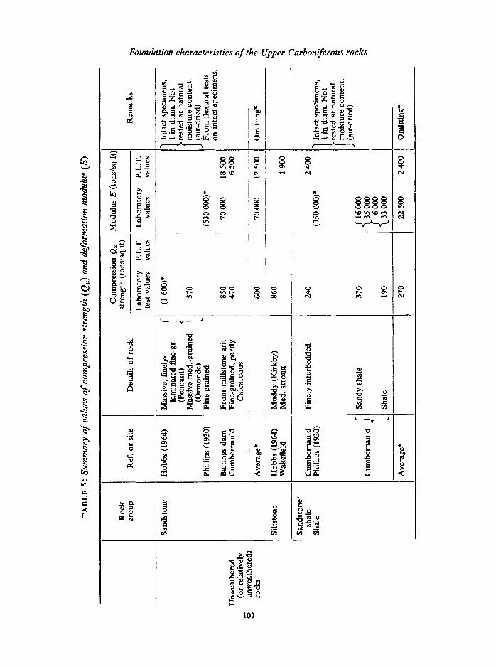
4. Review of data and summary The quantitative data on rock characteristics given in the paper has been in the form of values of compression strength (Q~,) and deformation modulus (E), these values being obtained both from laboratory tests on specimens from drill cores (or cored in the labora- tory from blocks) and in some cases on open-drive samples and from plate loading tests. It may be useful therefore to gather together the data to see if any picture emerges. This has been done in Table 5 where average values have been presented.
106
~
(A tr~
<
Foundation characteristics of the Upper Carboniferous rocks
.~. ~ ~ ~ ~~
.~.- .~.~= ~
~.~
~ ~~ �9 ~-.------~
2
~g ~ ! ~ ~"~1".~ p... ~
~ J
�9 ~ ~ I.~ I~ .~.~ ,.~
!
~ ~ r
~12 r12
~ ~ *o
,q. ~0
v ~
J
0 0
o
107
<

A. C. Meigh
I
.1
0 0
,.0
0
[11 III
~ o ~ ~
~l 0 0 0
e'. 0 ~
~ m
o
<
o o
o o ~ o
108
0
0 o

Foundation characteristics of the Upper Carboniferous rocks
In very round figures, compression strength values for the unweathered rocks, based on laboratory tests, range from 150 tons/sq ft for mudstones, 200-300 tons/sq ft for shales, to around 600 tons/sq ft for sandstones, ignoring the Pennant sandstone values on small air-dried specimens given by Hobbs. The decomposed rock products of the upper weathered zone on the other hand have compression strengths in the range 2 to 5 tons/sq ft.
LOADING IN TENSITY, TON S/SO.. FT. 0 10 20 30 4O 5O 60 [ 1 J I [ I 1
LOAD, TONS 20 40 60 80 I00
o.2 ~ ~-"--.,.~
~ 0 . 6 -
,
0 1 _ O ff
0'- 6" [ ....
4 ' - 6"1
9'- 6" I.
~ - 0 I'.L
i V , V l
35-7 " ' -
End of ol
G . L ~
" " ~ Blinding concyete Yellow CLAY] Fully
~weathered Blue CLAY J SHALE
@ Weak blue SHALE
(weathered) J . 1
~ Medium strong blue SHALE
A A I
SANDSTONE
of pile
1 '2 -
FIG. 8. Pile loading test results, Harrogate. (18 in diameter bored, cast-in situ piles.)
Values of deformation modulus, E, for the unweathered rocks show a marked difference between laboratory test values and values from plate loading tests. For the Millstone Grit sandstone at Baitings Dam, the E from laboratory tests is over five times higher than the E from plate loading tests, and for the Coal Measure shales at Cumbernauld the ratio appears to be higher.
For foundation considerations it is, of course, the plate loading test values which are significant, not the laboratory test values, since the field values include effects of rock structure, bedding, jointing, fissuring, etc. In some cases plate loading test values may be conservative because of stress relief below the pit. Considering E values from the plate loading tests, it would seem that, again in very round figures, for unweathered mudstone and shales, E is about 2 000 tons/sq ft (30 000 lb/sq in) and for unweathered sandstones roughly 12 000 tons/sq ft (180 000 lb/sq in). From the very limited data available it would appear that in the weathered sandstone and weathered mudstone, E falls to about
109

A. C. Neigh
one tenth of the corresponding values in unweathered rock. For the decomposed rock products, E is less than 100 tons/sq ft.
In addition to the values of compression strength and E, the paper has presented a number of loading test results for bored cast-in situ piles founded in Upper Carboniferous rocks. This data appears to support the view put forward in w 2 of this paper that in certain conditions such piles can support loads corresponding to the Code of Practice maximum working stress in the concrete, namely 48 tons/sq ft of pile cross-sectional area. The penetration into sound unweathered bedrock necessary to achieve this is about four pile diameters, in the case of shales and mudstones, reducing to about one pile diameter where the pile is founded in a thick band of sandstone, and as little as half a diameter if the sandstone is very hard. Some reduction in allowable bearing capacity may be required where there are steeply dipping strata or mudstones which deteriorate during boring.
Acknowledgements. This paper is presented by permission of Soil Mechanics Limited. The author also wishes to thank the following for permission to quote the results of work carried out for them:
Col. S. Maynard Lovell, C.B.E.E.R.D.T.C., County Engineer and Surveyor, West Riding of Yorkshire County Council (site invesitgation for Sheffield-Leeds Motorway, Wakefield); Mr A. S. Scott, B.sc. A.M.I.C.E.M.I.MUN.E., Chief Engineer, Cumbernauld Development Corporation, and F. R. Bullen & Partners (site investigation for Cumbernauld New Town Centre Development); Mr J. B. Bennett, M.I.C.E.M.I.MtrN.E., City Engineer, Surveyor and Planning Officer, City of Bristol (pile loading tests, Cumberland Basin Bridges Scheme); Mr James Drake, C.B.E.B.SC. M.I.C.E.M.I.MUN.E.P.PaNST.rt.E., County Surveyor and Bridgemaster, Lancashire County Council (piling for Gathurst Viaduct, Wigan; for this work Soil Mechanics Limited were sub-contractors to A. Monk & Company Limited who carried out the bridgeworks on behalf of Lancashire County Council, as agents for the Ministry of Transport; Mr Drake was the Engineer).
5. References CRUTCHLOW, S. B. 1966. The foundation properties of the Upper Shales, Proc. 1st. Int. Conf.
Rock Mech. Lisbon, Sept. 1966. HoBBs, D. W. 1964. Rock compressive strength, Colliery Engng 41, 287. INSTITUTION OF CIVIL ENGINEERS. Code of Practice CP4(1954) Foundations. MEIGH, A. C. (~ GREENLAND, S. W. 1965. In situ testing of soft rocks. Proc. 6th Int. Conf. Soil
Mech., Montreal 1, 73. PHILLIPS, n. W. 1930. The nature and physical properties of some Coal Measure strata. Trans.
Instn Min. Engrs 80, 212. THORBURN, S. 1966. Large diameter piles founded on bedrock. Symposium on Large Bored Piles.
London (Institution of Civil Engineers). WHITE, T. E. S., EVANS, R. H. & DENNIS, J. 1964. Baitings Dam. Horizontal and vertical deflec-
tions. Trans. 8th Int. Congr. large Dams, vol. 2, paper R11.
Submitted 4 April 1967. A. C. Meigh, M.SC.(ENG.) M.I.C.E.M.ASCE F.G.S.
Soil Mechanics Limited, 65 Old Church Street, London s w 3.
6. Appendix A: Description of rocks and overlying soils near Wakefield, Yorks,
including laboratory test values (A) SOILS OVERLYING MUDSTONE
The soils overlying the mudstone have generally been derived by weathering of the rock to form silty clays, mottled brown and grey in colour, and varying from firm to stiff in
110

Foundation characteristics of the Upper Carboniferous rocks
consistencies. These soils are generally up to 10 ft thick and exhibit at their base a gradual transition to weak, fragmented weathered mudstone. They exhibit a general increase in strength with depth as they grade from clays to weathered rock which in turn becomes stronger as the extent of weathering decreases. Coal seams and seatearth were encountered in these soils. The moisture contents of the soils are variable. Average and typical moisture content depth profiles for the soils and underlying rock are shown in Fig. 9a.
(a)
M U D S T O N E AREAS M O I S T U R E C O N T E N T - p e r c e n t
0 IO 2 0 3 0 4 0 SO
s
6 1 o
0 I . J
15
2 5 �9
I T Y P I C A L CURVE B.H, B216
(b)
SANDSTONE AREAS M O I S T U R E C O N T E N T - p e r cen t
O I 0 2 0 50
S
tLI r ..-
-I- IO I- n
I .....8 T Y P I C A L CURVE
B.H. R 293K
Average curve - - - T y p i c a l curve
FIo. 9. Moisture content-depth profiles, Wakefield. Mudstone (a) and sandstone (b) areas.
The decrease in moisture content with depth appears to be fairly gradual reaching an average of about 16 per cent at the weathered rock. Liquid limit has been plotted against plasticity index in Fig. 10a. The results of the undrained triaxial tests on specimens from open-drive samplers show the shear strength to vary between 500 lb/sq ft and 7 000 lb/ sq ft with an average of 2 800 lb/sq ft. The results of tests on the material from the transi- tional zone between the clay and the weathered mudstone are very variable probably
111

A. C. Meigh
largely due to disturbance in sampling. The results of oedometer tests again on specimens from open-drive samplers gave coefficients of compressibility between 0.004 and 0.054 sq ft/ton with an average of 0.014 sq ft/ton.
SOILS O V E R L Y I N G MUDSTONE .~ 6O
u
,- 5 0
' CH , J x 4 0
" ' S _z 3o cl ,,I
_, , MH OH G 2 0 CI - , ~
P" �9 �9
SF �9 I ,MI &OI
" sol" M' I (a) ,, o 0 2 0 4 0 6 0 8 0
L I Q U I D L I M I T -per c e n t
" ~ A - l ine
I 0 0
(b)
SOILS OVERLYING SANDSTONE --. 6 0
, i d . . . .
~, 50 Q.
• 4 0 ~ C H
z 3 o : l > .
20 CL ~ , ~ "
~t SF M &OI
Z" 0 :)L
O 20 40 60 80 | L I Q U I D L I M I T - p e r cent
, ~ A - l ine
IOO
FIG. 10. Plasticity charts, Wakefield. Soils overlying mudstone (a) and sandstone (b).
( B ) S O I L S O V E R L Y I N G S A N D S T O N E
The soils overlying the sandstone generally consist of a brown very clayey sand or sandy clay frequently containing sandstone fragments and varying in thickness from about 1 ft to 7 ft. The change from soil to weathered sandstone is generally fairly distinct. Average and typical moisture content depth profiles are shown in Fig. 9b and the liquid limit has been plotted against the plasticity index in Fig. 10b. Undrained triaxial tests gave strengths between 800 lb/sq ft and 10 000 lb/sq ft, with an average of 4 800 lb/sq ft. Oedometer tests gave coefficients of compressibility between 0.005 sq ft/ton and 01021 sq ft/ton with an average of 0.013 sq ft/ton.
( C ) M U D S T O N E S
These vary from slightly silty to very silty mudstones. They are generally massive and unbroken but have occasional small joints and fissures. The properties varied according to the composition of the mudstone and the degree of weathering. The moisture content of unweathered mudstones varied between about 5 and 11 per cent while the weathered
112

Foundation characteristics of the Upper Carboniferous rocks
mudstone increased in moisture content with the degree of weathering and generally ranged from about 11 to 16 per cent. The average unconfined compressive strength of the small number of mudstones specimens tested was 160 tons/sq ft but the strength of this material is likely to vary considerably due to variations in composition and the effect of stress relief on the specimen as indicated by fractures which appear in the drill cores.
(D) SANDSTONE AND SILTSTONE
These rocks vary in dominant grain size from medium sand to coarse silt and contain varying amounts of particles of silt and clay sizes which may form the cementing medium. They are brown or grey in colour and sometimes contain mudstone laminations and clay filled joints. The sandstone is generally stronger than siltstone and the average unconfined compressive strength of a small number of sandstone and siltstone specimens tested was 200 tons/sq ft with a range between 120 and 260 tons/sq ft. Weathering is normally confined to the upper few feet of the rock but where jointing is present weathering and iron-staining can penetrate to greater depths.
PLATES 7--8
PLATE 7. Selected simplified bore-hole logs, Wakefield.
PLATE 8. Effect of exposure on mudstone cores. (a) Cores composed mainly of variable silty mudstone from borehole 13708 at Bramley Lane, shortly after drilling; (b) the same cores after exposure in the core boxes for about two weeks, showing the typical breaking down of the mudstone into shaley fragments
due to weathering, April, 1963.
5jro 113

<
o
o
r~
~ 0_~ ,'O" 0
~ - - 0 0 ,~. ~M k - l - N
,,n ,:.E z
,:o~ O - - o " c~l I - ~ ca .:z
, , oT I - -
D E P T H B E L O W G.L..ft.
o o o o o o o o 2 o -- '~" ~ ,,o ~ ~ _ 0 I I ! ! ' ' ! I ' i i
:~. 1. l'llJ "I .I" I. I" l.l]lll ~~Ll I 111. I" I. I" IWI] II. I I!'111~[
- ~ . ,,, " i z
~- O = o ~ ~ ' a
o _~ . ~ , , , o ~ ~"~,:u o ._ez ,,,o._ ~.~ ~.~ ~'~
- g ~ ,,; ~ , . , P ~ ~ ~ -~ ~ . . . . ,,, .- ~ ~'~ v '~ ~ o
_~,. ,~ ~ d .--~ ~-~ ~ ~ ~ ~- '= : ._ ~ -~,- >. u~ ,,; . ~ _
._ -~ ~ c.~ -->'~ ~"
,_ o o ~ ' ~ , ~ o o ~.._~ o ~ , . , �9 , - , ~ " ~ u , , ~ o
- - U ) I / )
" " 1 . . I ' " ' : ' " " : ' , ' " ' " 1 ~,: :I! i ~ : ~ : ~ ~ �9 o >.o,_ ~,., ~ ,~ ,u w'L _u~u-s.- ~>. ~ , , u ~ > , , - ~ ' , ~ " o e- U ~ ' - �9
�9 --0 C ~ ~ S_ o,,,.... 0>- ~'c
,_.g B~
_ .~
~ , - ~ ~ '~
"--_~__.~ > , ~ "~
"~ ~ o ' ~ =~'- ,-~0 .=~ 0 ,_ r o_m
~- _g "~ u E " u
TU ' ) O ,,_~ O >
~__ o ~H,I I" I,r II~ IIIIHHIII! flHINII~ ilWl l"liH II I~ I111 IJ 11 II I.. 111~ I I II If I I II I.I 1 II H lil~
I o -C-- r ._ o, _..~ o
t-. =..~ O u u u ~ - > . ~ . ~
.,_ ~ ._o, ,_ . . g O ~ - ~ > "~ { ~
s S =i" o >.~..~ .. - - , , , - - ~_~.~. ,, =.. o _ o ~,, . ~ ~
= o - - , o ~ o ~ , - ' ~ ' ~ = o . -
" r > 0 0 0 0 U3 D O
N--~ I: ! : :IW Irl I. I I. I rl .lil ~ I. 11111 I .I I ~I N .I IIIBiIII ~I~I I:~ILII LIt IJ 1! nn d u ~
o. :
=~ ,~,~
u ' ~ e- 0 ~,..a ,,-. . ~ r ' 0
g;g ~ = . . -.~ooo- =. r ,,c O O �9 o u O
E u ' - , ~ .>.'- ~=,', ,-, ,o .s ~,.. ,- .~ .-
,- a: ~ ~ E o - . , ' - ,o 0
r,, ~ u J
o~,~,~,~ I~l~g~~ ~,--~ =,.~.~.~.,., 11 I. I" .II" ]l~II" I. I]I Jlr l.gl4ll'[lll~l'l1411" IW I'!
I ' -
~" I "~ ~ : ~o "~z'~ ~"
~ " "~ - - ~ o ~=o ~ - '- - 6 z , . o . E . ~ - . . ~
x ~-' I-. >
o ; 6 6 ; 8 " 6
~o ~o~ _ ~ o g
- ~._~~
~.~ ~ =
~ ' = - "~ ~ u i
~ z , . . - - o
~ 8 ~ o ~ ~: "~>"
~.-~ o i.~.;
' ~ E
o F"- "
. v O , ~ ~- Z ' ~
" ~ " 7 " ~ M 0 7 3 9 H l d 3 0
o
c~
o
o o
6 o
,.(3
(L)
E
r
r~

Q. Jl Engng Geol. Voi. 1, 1968 PLAXE 8
(a)
(b)
Effect of exposure on mudstone cores: (a) shortly after drilling, (b) after exposure for about two weeks.
(Full explanation on p. 113)