fortin electronic systems flash-link manager user guidecdn02.fortin.ca/download/16141/16141.pdf ·...
TRANSCRIPT

Fortin Electronic Systems Flash-Link Manager User Guide
Copyright © 2014 Flash Link Manager. All rights reserved. This guide is designed and developed by Fortin Electronic Systems.

Flash-Link Manager User Guide
F O R T I N E L E C T R O N I C S Y S T E M S Page 2
Table of Contents Interface Overview .................................................................................................................................................................. 3
Menu details ....................................................................................................................................................................... 3
File ................................................................................................................................................................................... 3
Tools ................................................................................................................................................................................ 3
Configuration .................................................................................................................................................................. 4
Help ................................................................................................................................................................................. 5
User Login Information ....................................................................................................................................................... 6
Tabs ......................................................................................................................................................................................... 7
UNIT Status Tab ................................................................................................................................................................... 7
UNIT Notes Tab ................................................................................................................................................................... 7
UNIT Updates Tab ............................................................................................................................................................... 8
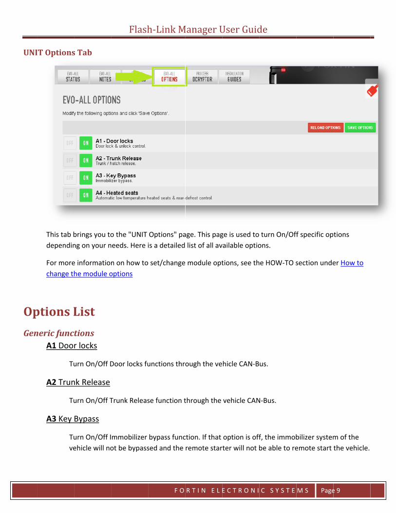
UNIT Options Tab ................................................................................................................................................................ 9
Options List ..................................................................................................................................................................... 9
DCRYPTOR Process Tab ......................................................................................................................................................... 15
Installation guides tab ........................................................................................................................................................... 16
Quick buttons ........................................................................................................................................................................ 17
Toggle ................................................................................................................................................................................ 17
Flash .................................................................................................................................................................................. 17
Quit ................................................................................................................................................................................... 17
HOW-TO ................................................................................................................................................................................ 18
How to Flash update a module to the recommended Firmware version. ........................................................................ 18
How to change the module options ................................................................................................................................. 21
How to use the DCRYPTOR Process .................................................................................................................................. 23
How to Flash Update the Flash-Link-2 Updater ................................................................................................................ 27
Troubleshooting .................................................................................................................................................................... 30

In
Me
nterfac
enu deta
File
Q
Tools
La
ce Ove
ails
Quit - Exits
anguage -
Flasherview
FlashLink M
Select the
English: SeFrançais: SPусский: S
h-Link M
F O
w
Manager s
desired la
ets the FlashSets the FlasSets the Flas
Manager U
R T I N E L E
software.
nguage.
Link ManagehLink ManaghLink Manag
User Guid
E C T R O N I
er display lager display lager display l
de
C S Y S T E
nguage to Eanguage to anguage to
M S Page
nglish. French. Russian.
e 3

Config
A
P
U
Sp
guratio
Automatic F
Autom
roxy Serve
Speciayour n
Unit Option
This isrecomSuppoinstea
Using firmw
pecial Unit
SwitchStarte
Flashon
Flash
matically flas
er Settings
al settings fonetwork adm
ns
s the OFFLINmmended to ort Team migd.
this menu mare currently
t
h/Toggle ther" mode.
h-Link M
F O
shes the nex
or computersministrator.
E menu to cuse the OFF
ght not be ab
may also resuy flashed in
e FlashLink M
Manager U
R T I N E L E
t plugged-in
s that use a
hange the mFLINE optionble to troub
ult in activatthe module
Manager con
User Guid
E C T R O N I
n module wit
Proxy Serve
module optios menu do tleshoot you
ting options .
nnection mo
de
C S Y S T E
th the curren
r to access t
ons. It is howto the fact thr setup. Use
that are not
de between
M S Page
ntly selected
the Internet.
wever not hat the Teche the options
t enabled fo
n "Bypass" or
e 4
d firmware.
. Check with
hnical s tab
r the
r "Remote

Help V
U
So
Fl
C
A
Visit Websit
Openssystembrowswebsit
User Guide
OpensManagYou ne
oftware Up
Check
lashLink Fi
Enters
For mosectio
ancel Flash
Exit/caupdate
About
OpensManag
Flashte s your operam's default ser on Fortinte.
s the FlashLiger User Guieed Acrobat
pdate
s online if th
rmware U
s the FlashLi
ore informan under How
hLink Upda
ancel FlashLe utility.
s the "Aboutger software
h-Link M
F O
ating
n’s
nk ide. t Reader or a
here is any n
pdate
nk2 Firmwar
tion on the w to Flash U
ate
Link2 Firmwa
t Copyright" e. Mainly us
Manager U
R T I N E L E
another PDF
newer versio
re update ut
FlashLink2 Fpdate the Fl
are update u
page. This psed when yo
User Guid
E C T R O N I
viewer soft
on of the Flas
tility to upda
Firmware upashLink2 Up
utility and br
page identifiou call the Te
de
C S Y S T E
ware installe
shLink Mana
ate the Flash
date utility, pdater
rings you bac
es the core vechnical Sup
M S Page
ed on your c
ager softwar
her.
see the HOW
ck to the mo
version of Flport Team.
e 5
computer.
re.
W-TO
odule
lash Link

Us
er Login
Welcom
Thno
Login
O
Register
Brto
N
Forgot P
Brin
Français
Se
Pусский
Se
n Inform
me USERNA
his informatot currently
pens a dialo
r Account
rings you to o use special
ote: This is t
Password
rings you to nstructions o
s
ets the Flash
й
ets the Flash
Flashmation
AME
ion tells youlogged in.
og box to let
the "New Ul firmwares o
the same acc
the "Forgoton how to re
hLink Manag
hLink Manag
h-Link M
F O
u which user
you login w
User" registraor if you call
count used o
Password" set your pas
ger display la
ger display la
Manager U
R T I N E L E
is currently
ith your use
ation page tol the Technic
on the forti
page. Just essword.
anguage to F
anguage to R
User Guid
E C T R O N I
logged in. "
ername and p
o create a necal Support T
n.ca website
nter your ac
French.
Russian.
de
C S Y S T E
Guest" wou
password.
ew account.Team.
e.
ccount emai
M S Page
ld mean tha
. An accoun
l address to
e 6
at you are
t is needed
receive

TaUNI
UNI
abs IT Status T
This windcurrently
IT Notes T
Is use to time this
Tab
dow, on the y connected.
ab
save any peunit is conn
Flash
left hand sid. On the righ
rsonal instalnected.
h-Link M
F O
de, providesht hand side
llation notes
Manager U
R T I N E L E
you with alyou will see
s for this veh
User Guid
E C T R O N I
l the informe information
hicle. These
de
C S Y S T E
ation on then about the
notes will be
M S Page
e module thaFlashLink2 d
e displayed t
e 7
at is device.
the next

UNI
IT Updates
This tab wsoftwarelatest tes
"Beta" vebe used i
1. Th2. If
For moreupdate a
s Tab
will bring yo than the on
sted and app
ersions are fif either:
he installatioTechnical S
e information module to t
Flash
u to the "UNne preloadedproved versi
for developm
on guide youupport has a
n on how tothe recomm
h-Link M
F O
NIT Updatesd. We recomon.
ment purpos
u are using sadvised you
flash your mmended Firm
Manager U
R T I N E L E
" page. Thismmend using
ses only and
specifies to uto use a BET
module, see ware version
User Guid
E C T R O N I
s page is useg the "RECO
are used at
use a BETA fTA firmware
the "HOW-Tn.
de
C S Y S T E
d to Flash thOMMENDED
your own ri
irmware e
TO" section
M S Page
he UNIT withUPDATE" w
isk. These sh
under How
e 8
h other hich is the
hould only
to Flash
UNI
OpGen
IT Options
This tab bdependin
For morechange th
ptions Lneric func
A1 Doo
Tu
A2 Trun
Tu
A3 Key
Tuve
s Tab
brings you tong on your n
e informationhe module o
List tions r locks
urn On/Off D
nk Release
urn On/Off T
Bypass
urn On/Off Iehicle will no
Flash
o the "UNIT needs. Here i
n on how tooptions
Door locks fu
Trunk Releas
mmobilizer ot be bypass
h-Link M
F O
Options" pais a detailed
set/change
unctions thr
se function t
bypass funcsed and the
Manager U
R T I N E L E
age. This pag list of all av
module opt
ough the ve
through the
ction. If that remote star
User Guid
E C T R O N I
ge is used to vailable optio
tions, see th
hicle CAN-B
vehicle CAN
option is offrter will not b
de
C S Y S T E
turn On/Offons.
he HOW-TO s
us.
N-Bus.
f, the immobbe able to re
M S Page
f specific op
section unde
bilizer systememote start
e 9
tions
er How to
m of the the vehicle.
Flash-Link Manager User Guide
F O R T I N E L E C T R O N I C S Y S T E M S Page 10
A4 Heated Seats (Rear defrost)
Turn On/Off Embedded Heated seats and Rear defrost control through the vehicle CAN-Bus. Will only work on vehicles that support heated seats and Rear defrost control trough the vehicles CAN-Bus. Will be automatically activated if option (A5 Aux. 1) AND (A6 Aux. 2) are OFF. Will be manually activated if (A5 Aux. 1) OR (A6 Aux. 2) is ON. On some older GM or Chrysler vehicle (J1850), heated seats are automatically activated if outside temperature is under 5 Celcius (41 Fahrenheit).
A5 Aux. 1
Turn On/Off vehicle specific options (Sliding doors, Gas cap, Parking lights, Heated seats (see A4), Rear defrosts…
A6 Aux. 2
Turn On/Off vehicle specific options (Sliding doors, Gas cap, Parking lights, Heated seats (see A4), Rear defrosts…
A7 Foot-Brake
Turn On/Off Foot-Brake monitoring through the vehicle CAN-Bus.
A8 Hand-Brake
Turn On/Off Hand-Brake monitoring through the vehicle CAN-Bus.
A9 Door Trigger
Turn On/Off Door Trigger monitoring through the vehicle CAN-Bus.
A10 Trunk Trigger
Turn On/Off Trunk Trigger monitoring through the vehicle CAN-Bus.
A11 Hood Trigger
Turn On/Off Trunk Trigger monitoring through the vehicle CAN-Bus.

Flash-Link Manager User Guide
F O R T I N E L E C T R O N I C S Y S T E M S Page 11
B1 Unlock driver door priority
Turn On/Off the feature that will unlock the driver door only on the first unlock button press and then all other doors on the second unlock button press.
B2 Extended unit’s inputs/outputs for RF kit(Datalink Remote starter)
Turn On/Off special pin out that add or remove analog signal wires for specific RF-Kit setups.
B3 Unlock double pulse
Turn On/Off the double pulse on the unlock output on specific setups that use analog signal for unlocking.
OEM remote monitoring C1 OEM remote status (LOCK/UNLOCK) monitoring
Turn On/Off vehicle OEM remote monitoring through the vehicle CAN-Bus. That information will then be sent to the remote starter through Datalink.
Remote-Starter D1 Stand-Alone Enable (3x Lock) EVO-ALL ONLY
Turn On/Off the UNIT embedded Stand Alone remote starter. The vehicle will remote start when the LOCK button is pressed 3 times on the OEM remote. A remote car starter installation can be completed using only the interface module. An aftermarket remote car starter is not required. If using RF-Kit for remote starting, D1 Stand-Alone Enable must to be ON. For more information see "How to connect and configure an RF-Kit". For use on **AUTOMATIC VEHICLES ONLY**. Will only work on vehicles that are compatible with 3x Lock Remote Starter.
D1.1 Lock-Unlock-Lock EVO-ALL ONLY
Turn On/Off the feature to use Lock-Unlock-Lock sequence on the vehicle OEM remote to activate the UNIT Stand-Alone Remote Starter system (instead of Lock-Lock-Lock).
D1.2 Disable second start attempt EVO-ALL ONLY
By default, the UNIT is set to retry to start if the first attempt fails. If you turn that option On, The UNIT will not retry to start if the first attempt fails.

Flash-Link Manager User Guide
F O R T I N E L E C T R O N I C S Y S T E M S Page 12
D1.3 Diesel mode EVO-ALL ONLY
Turn On/Off the feature that use special timing delay (Wait to start) and special runtime for Diesel Engine.
D1.4 3 Minutes EVO-ALL ONLY
Sets the Stand-Alone remote starter runtime to 3 minutes on gas engines and 6 minutes on Diesel Engine
D1.5 7 Minutes EVO-ALL ONLY
Sets the Stand-Alone remote starter runtime to 7 minutes on gas engines and 14 minutes on Diesel Engine
D1.6 15 Minutes EVO-ALL ONLY
Sets the Stand-Alone remote starter runtime to 15 minutes on gas engines and 30 minutes on Diesel Engine
D2 Unlock before/Lock after
Sets the UNIT to unlock and disarm before remote start and then relock after it completes the start sequence. It will also relock and rearm 10 seconds after shutdown.
This option is used to disarm the vehicle's OEM Alarm.
D3 Shutdown on door opening
Sets the UNIT to shutdown the engine on door opening. The customer will then have to restart the engine. (Used for security and compatibility)
D4 Hybrid Mode
Sets the UNIT to be used on Hybrid Vehicles that do not generate a proper tach signal. The UNIT will emulate a tach signal as soon as it detect that the hybrid vehicle is in “Ready to be driven” state. Both on its analog output and through Datalink.
D5 Lock after start
Sets the UNIT to lock the vehicle after it complete the start sequence. It will also relock and rearm 10 seconds after shutdown.

Flash-Link Manager User Guide
F O R T I N E L E C T R O N I C S Y S T E M S Page 13
D6 Push-To-Start
Sets the module to be used on a Push-To-Start vehicle. Only required when the installation guide for the vehicle demands it.
Special functions E1 GPS I/O EVO-ALL ONLY
Sets special outputs for specific GPS units. The Tach output(Pink) will send constant 12v if a tach signal is detected on the vehicle Can-bus and switch to 0v when the tach signal is lost. The Handbrake(Brown/White) output will provide the vehicle OEM Alarm status with Ground(-) if armed and with an open circuit if disarmed.
Datalink protocol F1 Fortin
Sets the UNIT in the Fortin Datalink protocol. Use this option if you want to use the Datalink Port with a device that supports Fortin Datalink protocol. By default, the unit is always in Fortin protocol unless otherwise changed.
F2 AP/OFA Datalink
Sets the UNIT in the AP/OFA Datalink protocol. Use this option if you want to use the Datalink Port with a device that supports AP/OFA Datalink protocol.
F3 D2D
Sets the UNIT in the D2D Datalink protocol. Use that option if you want to use the Datalink Port with a device that supports D2D Datalink protocol.
EVO-ALARM Evo alarm enable EVO-ALL ONLY
Turn On/Off the UNIT embedded Alarm Security system. No Aftermarket Alarm System required. Enable vehicle Security & Alarm functions with the interface module that will use the vehicle's horn as a sound monitor.
G1.1 Horn EVO-ALL ONLY
Sets the EVO-ALARM to use the horn output as a sound monitor.

Flash-Link Manager User Guide
F O R T I N E L E C T R O N I C S Y S T E M S Page 14
G1.2 Siren EVO-ALL ONLY
Sets the EVO-ALARM to use the siren output as a sound monitor.
G2 Chirp confirmation EVO-ALL ONLY
Will chirp 1X on first Lock press and chirp 2X on first Unlock press.
G3 1st lock/unlock silent EVO-ALL ONLY
Will chirp 1X on second Lock press and chirp 2X on second Unlock press. First lock and unlock press are silent.
G4 Smart rearm EVO-ALL ONLY
Sets the EVO-ALARM to rearm itself if no door is opened within 30 seconds after unlock is pressed.
Supported RF Kits Supported RF Kits enable
Turn On/Off the UNIT RF Kits compatibility mode. Use that option to use the UNIT with extended Radio Frequency kits when the vehicle OEM remote range is not enough. See How to connect and configure a RF-Kit.
H1 Fortin (AST, DSE, Atom, etc.)
Sets the UNIT RF kits compatibility mode to use special settings for AST, DSE, Atom branded modules. See How to connect and configure an Atom.
H2 Fortin 2
Sets the UNIT RF kits compatibility mode to use special settings for Fortin module.
H3 CrimeStopper
Sets the UNIT RF kits compatibility mode to use special settings for CrimeStopper branded modules. See How to connect and configure a CrimeSopper Revo.
H4 AudioVox FLRF, DEI SmartStart
Sets the UNIT RF kits compatibility mode to use special settings for AudioVox and SmartStart branded modules. See How to connect and configure an AudioVox FLRF/Omega.

DC
H5 DEI X
Seco
H6 First
Seto
CRYPT
This tab wto bypassinstallatiowill then then be s
For moreuse the D
XL202
ets the UNITonnect and c
tTech FT-D
ets the UNITo connect an
TOR Pr
will bring yos the factoryon manual tbe sent to t
sent back to
e informationDCRYPTOR P
FlashT RF kits comconfigure an
100
T RF kits comnd configure
rocess T
u to the Proy immobilizeo sample th
the DCRYPTOyour modul
n on how torocess
h-Link M
F O
mpatibility mn XL202.
mpatibility man FT-D100
Tab
ocess DCRYPTer. Follow thee informatio
OR’s Super Cle.
use the DCR
Manager U
R T I N E L E
ode to use s
ode to use s0.
TOR Page. Te steps descon from the Calculator, th
RYPTOR Pro
User Guid
E C T R O N I
special settin
special settin
he DCRYPTOcribed in thevehicle's im
hat will calcu
cess, see the
de
C S Y S T E
ngs for DEI X
ngs for FirstT
OR is used to programmimobilizer sy
ulate the Key
e HOW-TO s
M S Page
XL202. See H
Tech FT-D10
o calculate thng procedur
ystem. That iy Data. Key D
section unde
e 15
How to
00. See How
he Key Datare of the information Data will
er How to

Ins
stallatio
Will bringthe curreinstalled
on guid
g you to quicently connecon your com
Flashdes tab
ck referencected UNIT. Mmputer to vie
h-Link M
F O
e and compleMake sure yo
ew them.
Manager U
R T I N E L E
ete install guou have Acro
User Guid
E C T R O N I
uide links avobat Reader
de
C S Y S T E
ailable for thor any PDF v
M S Page
he selected viewer Softw
e 16
vehicle with
ware h

Qu
uick b
Toggle
WSt
Flash
StFi
Quit
W
button
Will switch/totarters.
tarts the flasrmware ver
Will exit Flash
Flashns
oggle the Fla
sh update prsion is selec
h Link Manag
h-Link M
F O
ash Link Man
rocess with tted, nothing
ger software
Manager U
R T I N E L E
nager conne
the selectedg will happen
e.
User Guid
E C T R O N I
ction mode
firmware inn.
de
C S Y S T E
to be use w
n "UNIT Upd
M S Page
ith Bypasses
ates" Tab. If
e 17
s or Remote
f no

Flash-Link Manager User Guide
F O R T I N E L E C T R O N I C S Y S T E M S Page 18
HOW-TO
How to Flash update a module to the recommended Firmware version.
1. Plug in the Flash-Link-2 updater into the computer’s USB port with the provided USB cable.
2. Run Flash Link Manager Software.
3. Plug in the Module you want to Flash update with the provided DATALINK cable.

Flash-Link Manager User Guide
F O R T I N E L E C T R O N I C S Y S T E M S Page 19
4. Select your vehicle in the top selection box.
5. Open the "UNIT Updates" Tab.
6. Click on the RECOMMENDED UPDATE button. The Firmware selection will turn GREEN and a FLASH UPDATE button will appear.

Flash-Link Manager User Guide
F O R T I N E L E C T R O N I C S Y S T E M S Page 20
7. Click on the FLASH UPDATE button. Flash update process will start.
A progress bar at the bottom of the Flash Link Manager software will indicate the process completion percentage.
When the Flash Update process is done, you will see a "UNIT update successful" message
And the Progress bar will reach 100%
8. Disconnect the module and you are ready to continue with the vehicle installation or programming.

Flash-Link Manager User Guide
F O R T I N E L E C T R O N I C S Y S T E M S Page 21
How to change the module options 1. Plug in the Flash-Link-2 updater into the computer’s USB port with the provided USB
cable.
2. Run Flash Link Manager Software.
3. Plug in the Module you want to Flash update with the provided DATALINK cable.

Flash-Link Manager User Guide
F O R T I N E L E C T R O N I C S Y S T E M S Page 22
4. Click on UNIT OPTIONS tab.
5. Turn On/Off desired option by using the ON or OFF buttons.
6. Click SAVE OPTIONS.

Flash-Link Manager User Guide
F O R T I N E L E C T R O N I C S Y S T E M S Page 23
7. Wait for the Options Saved message to appear in the top right corner.
8. Disconnect the module and test in the vehicle.
How to use the DCRYPTOR Process 1. Flash update your module to the installation manual recommended Firmware version.
See “How to Flash update a module to the recommended Firmware version” section.
2. Proceed with the vehicle installation according to your installation manual.
3. Follow the steps described in the programming procedure of the installation manual to sample the information from the vehicle's immobilizer system.
4. Plug in the Flash-Link-2 updater into the computer’s USB port with the provided USB cable.
5. Run Flash Link Manager Software.

Flash-Link Manager User Guide
F O R T I N E L E C T R O N I C S Y S T E M S Page 24
6. Plug in the Module with the provided DATALINK cable.
7. Click on the Process DCRYPTOR Tab

Flash-Link Manager User Guide
F O R T I N E L E C T R O N I C S Y S T E M S Page 25
8. Click on SEND DATA button
9. The immobilizer data is now being analyzed by the DCRYPTOR servers and a new key code is being generated. Please wait as this process may take a few minutes.
Flash-Link Manager User Guide
F O R T I N E L E C T R O N I C S Y S T E M S Page 26
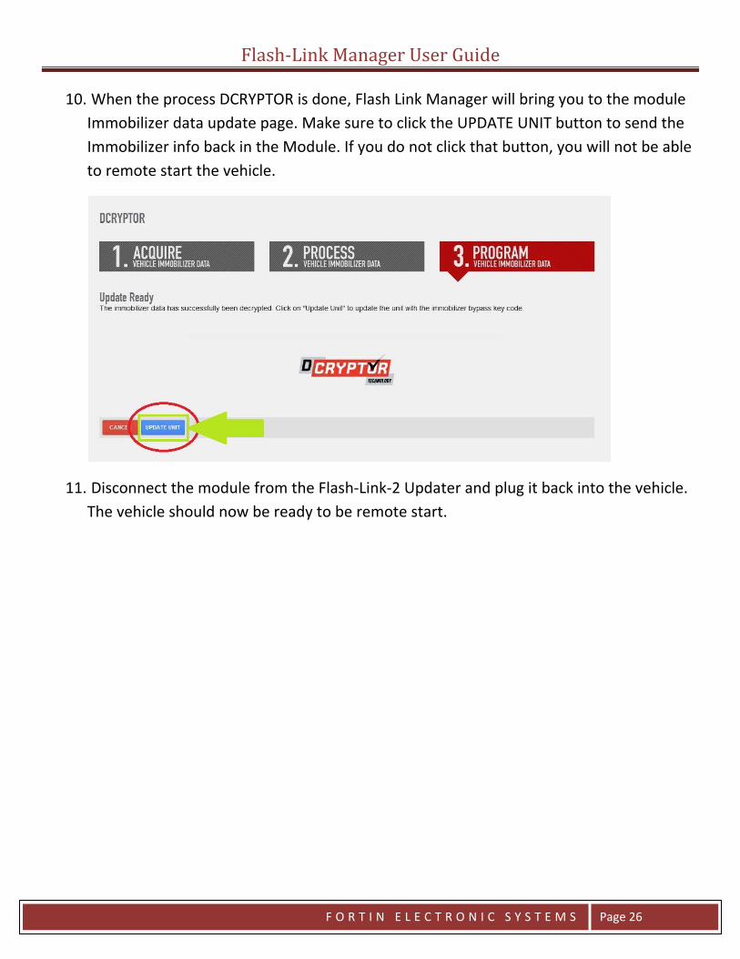
10. When the process DCRYPTOR is done, Flash Link Manager will bring you to the module Immobilizer data update page. Make sure to click the UPDATE UNIT button to send the Immobilizer info back in the Module. If you do not click that button, you will not be able to remote start the vehicle.
11. Disconnect the module from the Flash-Link-2 Updater and plug it back into the vehicle. The vehicle should now be ready to be remote start.

Flash-Link Manager User Guide
F O R T I N E L E C T R O N I C S Y S T E M S Page 27
How to Flash Update the Flash-Link-2 Updater 1. Run Flash Link Manager Software.
2. Plug in the Flash-Link-2 updater into the computer’s USB port with the provided USB
cable.
3. Click on Help and then on Flash Link Firmware Update
4. Disconnect the USB cable

Flash-Link Manager User Guide
F O R T I N E L E C T R O N I C S Y S T E M S Page 28
5. Wait 5 sec and reconnect the USB cable
6. Click on FLASH-LINK UPDATER UPDATES
7. Click on RECOMMENDED UPDATE. The selected version will turn green.

Flash-Link Manager User Guide
F O R T I N E L E C T R O N I C S Y S T E M S Page 29
8. Click on FLASH UPDATE.
A progress bar at the bottom of Flash Link Manager software will indicate the process completion percentage.
9. When the Flash Update process is done, you will see an FLASH-LINK UPDATER update
successful message
And the Progress bar will reach 100%
10. Disconnect the USB cable from the FLASH-LINK-2 updater, wait 5 seconds and plug it back in.

TrHere
This c
This cLINK-visitihttp:
“When I
roubles are some sce
can be cause
1.
2.
3.
can be cause -MANAGER. Tng //fortin.ca/e
plug a Fort
“I try to
shootinenarios you m
d by:
. FLASH-LINConnection
. A DATALINcable to gemode, it is
. A Broken /for broken
by using an oTry updating t
n/support/fla
Flash
in Unit in t
do DCRYPT
ng may encounte
K-MANAGER n Mode.
NK cable that et a SOLID RE
normal to ha/ Defective DA wires. If not
obsolete versto the latest v
ashlinkmanag
h-Link M
F O
he FLASH-L
TOR but wh
er while using
is not set to B
has not beenD light. NOTEave 3 flashingATALINK cablesure, try usin
ion of FLASH-version by
ger.html
Manager U
R T I N E L E
LINK-2, I ge
hen I click S
g the Flash-Lin
BYPASS Conn
well insertedE, if you conneg lights. e. Inspect you
ng another ca
-
User Guid
E C T R O N I
t 3 flashing
SEND DATA
nk Manager.
ection Mode
d. Try to discoect an EVO-O
ur DATALINK ble.
de
C S Y S T E
g lights on t
I get an er
. Click TOGG
onnect and reONE in REMOT
cable for loo
M S Page
the Fortin U
rror”
LE to switch t
econnect the TE-STARTER c
se/poor conn
e 30
Unit.”
to Bypass
DATALINK connection
nections and

Someopenhttp:down
You ato m
This w
Pleaslink_
This w
Pleaslink_
e computers n a Browser w//fortin.ca/enload the late
are right. Afteake sure that
will happen if
se see this art_updater_exch
will happen if
se see this art_updater_exch
“I
“After fla
“
are not set towindow. Open
n/support/flaest version.
er Flashing a Ft the Fortin U
f the Flash-Lin
ticle about thhange.html
f the Flash-Lin
ticle about thhange.html
get a New
ashing a Fo
“When I try
“Whe
Flasho let FLASH-LIn your browseashlinkmanag
Fortin Unit, ynit gets comp
nk Updater is
he Flash-Link U
nk Updater is
he Flash-Link U
Version wi
ortin Unit, I
y to go to th
en I try to up
h-Link M
F O
INK-MANAGEer and got to ger.html to
you need to dpletely reiniti
s not updated
Updater Exch
s not updated
Updater Exch
indow, but
cannot do
he "UNIT Op
pdate the F
Manager U
R T I N E L E
ER
isconnect andalized with th
d and does ha
hange: http://
d and does ha
hange: http://
when I clic
anything e
ptions" tab
Flash-Link U
User Guid
E C T R O N I
d reconnect ihe new loade
ve the latest
/fortin.ca/en/
ve the latest
/fortin.ca/en/
ck Downloa
else with th
b it just disc
Updater, I g
de
C S Y S T E
t to do any otd firmware.
firmware loa
/news/701-fla
firmware loa
/news/701-fla
ad, nothing
he FLASH-LI
connects th
get an erro
M S Page
ther changes
aded.
ash-
aded.
ash-
happen”
INK-MANAG
he UNIT”
r”
e 31
. We do this
GER”