fortigate admin guide 4.0 mr2
TRANSCRIPT
FortiGate™
Version 4.0 MR2Administration Guide
This document was published shortly before the release of FortiOS 4.0 MR2 and, therefore,contains only information that was gathered at the date of publication. This document will beupdated by May, 2010. For more information, contact [email protected].
FortiGate Administration GuideVersion 4.0 MR226 March 2009 01-420-89802-20100326
© Copyright 2010 Fortinet, Inc. All rights reserved. No part of this publication including text, examples, diagrams or illustrations may be reproduced, transmitted, or translated in any form or by any means, electronic, mechanical, manual, optical or otherwise, for any purpose, without prior written permission of Fortinet, Inc.
TrademarksDynamic Threat Prevention System (DTPS), APSecure, FortiASIC, FortiBIOS, FortiBridge, FortiClient, FortiGate®, FortiGate Unified Threat Management System, FortiGuard®, FortiGuard-Antispam, FortiGuard-Antivirus, FortiGuard-Intrusion, FortiGuard-Web, FortiLog, FortiAnalyzer, FortiManager, Fortinet®, FortiOS, FortiPartner, FortiProtect, FortiReporter, FortiResponse, FortiShield, FortiVoIP, and FortiWiFi are trademarks of Fortinet, Inc. in the United States and/or other countries. The names of actual companies and products mentioned herein may be the trademarks of their respective owners.
Contents
F0h
ContentsIntroduction ............................................................................................ 17Fortinet products .......................................................................................................... 17
Before you begin........................................................................................................... 18
How this guide is organized......................................................................................... 18
Document conventions ................................................................................................ 20IP addresses............................................................................................................. 20Cautions, Notes and Tips ......................................................................................... 20Typographical conventions ....................................................................................... 21CLI command syntax ................................................................................................ 21
Registering your Fortinet product............................................................................... 23
Fortinet products End User License Agreement ....................................................... 23
Customer service and technical support.................................................................... 23
Training .......................................................................................................................... 23
Fortinet documentation ............................................................................................... 24Tools and Documentation CD................................................................................... 24Fortinet Knowledge Base ......................................................................................... 24Comments on Fortinet technical documentation ..................................................... 24
Web-based manager .............................................................................. 25Common web-based manager tasks........................................................................... 25
Connecting to the web-based manager.................................................................... 26Modifying current settings......................................................................................... 26Changing your FortiGate administrator password .................................................... 27Changing the web-based manager language........................................................... 27Changing administrative access to your FortiGate unit ............................................ 27Changing the web-based manager idle timeout ....................................................... 28Switching VDOMs..................................................................................................... 28Connecting to the FortiGate CLI from the web-based manager ............................... 28Contacting Customer Support .................................................................................. 28
Using FortiGate Online Help ........................................................................................ 29Searching the online help ......................................................................................... 30
Web-based manager pages.......................................................................................... 31Using the web-based manager menu....................................................................... 32Using web-based manager lists................................................................................ 32Adding filters to web-based manager lists ................................................................ 33Using page controls on web-based manager lists .................................................... 34Using column settings to control the columns displayed .......................................... 35Using filters with column settings.............................................................................. 35
ortiGate Version 4.0 MR2 Administration Guide1-420-89802-20100326 3ttp://docs.fortinet.com/ • Feedback
Contents
System Dashboard................................................................................. 37Dashboard overview ..................................................................................................... 38
Adding widgets to a dashboard ................................................................................ 38VDOM and global dashboards.................................................................................. 39
System Information....................................................................................................... 39Configuring system time ........................................................................................... 41Changing the FortiGate unit host name.................................................................... 41Changing the FortiGate firmware............................................................................. 42
License Information ...................................................................................................... 42
Unit Operation ............................................................................................................... 45
System Resources ........................................................................................................ 46Viewing operational history....................................................................................... 46
Alert Message Console................................................................................................. 47
Log and Archive Statistics ........................................................................................... 48Viewing DLP archive information on the Statistics widget ........................................ 49Viewing the Attack Log ............................................................................................. 50
CLI Console ................................................................................................................... 50
Top Sessions................................................................................................................. 51
Top Viruses.................................................................................................................... 53
Top Attacks.................................................................................................................... 53
Traffic History................................................................................................................ 54
Top Policy Usage .......................................................................................................... 54
DLP Archive Usage ....................................................................................................... 55
RAID monitor ................................................................................................................. 56
Top Application Usage ................................................................................................. 58
Disk Status..................................................................................................................... 59
P2P Usage...................................................................................................................... 59
Per-IP Bandwidth Usage............................................................................................... 59
VoIP Usage .................................................................................................................... 60
IM Usage ........................................................................................................................ 60
FortiGuard...................................................................................................................... 60
........................................................................................................................................ 60
Firmware management practices ......................................................... 61Backing up your configuration .................................................................................... 62
Backing up your configuration through the web-based manager ............................. 62Backing up your configuration through the CLI......................................................... 62Backing up your configuration to a USB key ............................................................ 63
Testing firmware before upgrading............................................................................. 64
FortiGate Version 4.0 MR2 Administration Guide4 01-420-89802-20100326
http://docs.fortinet.com/ • Feedback
Contents
F0h
Upgrading your FortiGate unit..................................................................................... 65Upgrading to FortiOS 4.0 through the web-based manager.................................... 65Upgrading to FortiOS 4.0 through the CLI ................................................................ 66Verifying the upgrade................................................................................................ 67
Reverting to a previous firmware image..................................................................... 68Downgrading to a previous firmware through the web-based manager ................... 68Verifying the downgrade........................................................................................... 69Downgrading to a previous firmware through the CLI .............................................. 69
Restoring your configuration....................................................................................... 71Restoring your configuration settings in the web-based manager............................ 71Restoring your configuration settings in the CLI ....................................................... 71
Using virtual domains............................................................................ 73Virtual domains ............................................................................................................. 73
Benefits of VDOMs ................................................................................................... 73VDOM configuration settings .................................................................................... 74Global configuration settings .................................................................................... 76
Enabling virtual domains ............................................................................................. 77
Configuring VDOMs and global settings .................................................................... 78VDOM licenses ......................................................................................................... 79Creating a new VDOM.............................................................................................. 80Disabling a VDOM .................................................................................................... 80Working with VDOMs and global settings................................................................. 81Adding interfaces to a VDOM ................................................................................... 82Inter-VDOM links ...................................................................................................... 82Assigning an interface to a VDOM............................................................................ 83Assigning an administrator to a VDOM..................................................................... 84Changing the management VDOM........................................................................... 84Switching between VDOMs ...................................................................................... 85
Configuring VDOM resource limits ............................................................................. 85Setting VDOM global resource limits ........................................................................ 86Configuring resource usage for individual VDOMs................................................... 86
ortiGate Version 4.0 MR2 Administration Guide1-420-89802-20100326 5ttp://docs.fortinet.com/ • Feedback
Contents
System Network ..................................................................................... 89Configuring interfaces.................................................................................................. 89
Switch Mode ............................................................................................................. 92Configuring interface settings ................................................................................... 92Adding VLAN interfaces............................................................................................ 95Adding loopback interfaces....................................................................................... 95Adding 802.3ad aggregate interfaces....................................................................... 96Adding redundant interfaces..................................................................................... 97Configuring DHCP on an interface ........................................................................... 98Configuring PPPoE on an interface.......................................................................... 99Configuring Dynamic DNS on an interface ............................................................... 99Configuring virtual IPSec interfaces........................................................................ 100Configuring administrative access to an interface .................................................. 101Configuring interface status detection for gateway load balancing......................... 101Changing interface MTU packet size...................................................................... 102Adding secondary IP addresses to an interface ..................................................... 103Adding software switch interfaces .......................................................................... 105Adding an sFlow agent to a FortiGate interface ..................................................... 105
Configuring zones....................................................................................................... 107
Configuring the modem interface.............................................................................. 107Configuring modem settings ................................................................................... 108Redundant mode configuration............................................................................... 110Standalone mode configuration .............................................................................. 110Adding firewall policies for modem connections ..................................................... 111Connecting and disconnecting the modem............................................................. 111Checking modem status ......................................................................................... 112
Configuring Networking Options............................................................................... 112DNS Servers........................................................................................................... 113
Configuring FortiGate DNS services........................................................................ 113About split DNS ...................................................................................................... 113Configuring FortiGate DNS services....................................................................... 114Configuring the FortiGate DNS database ............................................................... 116
Configuring the explicit web proxy ........................................................................... 117Configuring explicit web proxy settings................................................................... 118
Configuring WCCP...................................................................................................... 120
Routing table (Transparent Mode)............................................................................. 121
System Wireless................................................................................... 123FortiWiFi wireless interfaces ..................................................................................... 123
Wireless settings......................................................................................................... 124Adding a wireless interface..................................................................................... 125
Wireless MAC Filter .................................................................................................... 127Managing the MAC Filter list................................................................................... 127
FortiGate Version 4.0 MR2 Administration Guide6 01-420-89802-20100326
http://docs.fortinet.com/ • Feedback
Contents
F0h
Wireless Monitor ......................................................................................................... 127
Rogue AP detection .................................................................................................... 128Viewing wireless access points .............................................................................. 129
System DHCP Server ........................................................................... 131FortiGate DHCP servers and relays .......................................................................... 131
Configuring DHCP services ....................................................................................... 132Configuring an interface as a DHCP relay agent.................................................... 132Configuring a DHCP server .................................................................................... 132
Viewing address leases.............................................................................................. 134Reserving IP addresses for specific clients ............................................................ 134
System Config ...................................................................................... 135HA ................................................................................................................................. 135
HA options .............................................................................................................. 135Cluster members list ............................................................................................... 137Viewing HA statistics .............................................................................................. 138Changing subordinate unit host name and device priority...................................... 139Disconnecting a cluster unit from a cluster ............................................................. 139
SNMP............................................................................................................................ 140Configuring SNMP.................................................................................................. 141Configuring an SNMP community........................................................................... 141Fortinet MIBs .......................................................................................................... 143Fortinet and FortiGate traps.................................................................................... 144Fortinet and FortiGate MIB fields............................................................................ 147
Replacement messages ............................................................................................. 151VDOM and global replacement messages ............................................................. 152Viewing the replacement messages list.................................................................. 152Changing replacement messages .......................................................................... 153Mail replacement messages ................................................................................... 153HTTP replacement messages ................................................................................ 154FTP replacement messages................................................................................... 155NNTP replacement messages................................................................................ 156Alert Mail replacement messages........................................................................... 156Spam replacement messages ................................................................................ 157Administration replacement message..................................................................... 158User authentication replacement messages........................................................... 158FortiGuard Web Filtering replacement messages .................................................. 159IM and P2P replacement messages....................................................................... 160Endpoint NAC replacement messages................................................................... 160NAC quarantine replacement messages ................................................................ 161Traffic quota control replacement messages.......................................................... 162SSL VPN replacement message ............................................................................ 162Replacement message tags ................................................................................... 162
ortiGate Version 4.0 MR2 Administration Guide1-420-89802-20100326 7ttp://docs.fortinet.com/ • Feedback
Contents
Operation mode and VDOM management access ................................................... 163Changing the operation mode ................................................................................ 164Management access............................................................................................... 164
System Admin ...................................................................................... 167Administrators............................................................................................................. 167
Viewing the administrators list ................................................................................ 169Configuring an administrator account ..................................................................... 169Changing an administrator account password........................................................ 170Configuring regular (password) authentication for administrators .......................... 170Configuring remote authentication for administrators ............................................. 171Configuring PKI certificate authentication for administrators .................................. 176
Admin profiles ............................................................................................................. 178Viewing the admin profiles list ................................................................................ 181Configuring an admin profile................................................................................... 181
Central Management................................................................................................... 182
Settings ........................................................................................................................ 183
Monitoring administrators.......................................................................................... 184
FortiGate IPv6 support ............................................................................................... 185Configuring IPv6 on FortiGate units........................................................................ 185
System Certificates.............................................................................. 189Local Certificates ....................................................................................................... 190
Generating a certificate request.............................................................................. 191Downloading and submitting a certificate request .................................................. 192Importing a signed server certificate....................................................................... 192Importing an exported server certificate and private key ........................................ 192Importing separate server certificate and private key files...................................... 193
Remote Certificates .................................................................................................... 193Importing Remote (OCSP) certificates ................................................................... 194
CA Certificates ............................................................................................................ 194Importing CA certificates......................................................................................... 195
CRL............................................................................................................................... 195Importing a certificate revocation list ...................................................................... 195
System Maintenance............................................................................ 197Maintenance overview ................................................................................................ 197
Configuration Revision............................................................................................... 198
Firmware ...................................................................................................................... 199Backing up and restoring configuration files ........................................................... 200
FortiGate Version 4.0 MR2 Administration Guide8 01-420-89802-20100326
http://docs.fortinet.com/ • Feedback
Contents
F0h
FortiGuard.................................................................................................................... 201FortiGuard Distribution Network ............................................................................. 201FortiGuard services ................................................................................................ 202Configuring the FortiGate unit for FDN and FortiGuard subscription services ....... 203
Troubleshooting FDN connectivity ........................................................................... 207
Updating antivirus and attack definitions................................................................. 207
Enabling push updates............................................................................................... 209Enabling push updates when a FortiGate unit IP address changes....................... 209Enabling push updates through a NAT device ....................................................... 210
Advanced ..................................................................................................................... 212Creating script files ................................................................................................. 213Uploading script files .............................................................................................. 214
Adding VDOM Licenses.............................................................................................. 214
Disk............................................................................................................................... 215
AMC module configuration ................................................................. 217Configuring AMC modules......................................................................................... 217
Auto-bypass and recovery for AMC bridge module ................................................ 218
Enabling or disabling bypass mode for AMC bridge modules............................... 219
Configuring RAID................................................................................. 221Configuring the RAID array........................................................................................ 221
RAID disk configuration .......................................................................................... 221
RAID levels .................................................................................................................. 222
Rebuilding the RAID array.......................................................................................... 223Why rebuild the RAID array? .................................................................................. 224How to rebuild the RAID array ................................................................................ 224
Router Static ........................................................................................ 227Routing concepts ....................................................................................................... 227
How the routing table is built .................................................................................. 228How routing decisions are made ........................................................................... 228Multipath routing and determining the best route ................................................... 228Route priority ......................................................................................................... 229Blackhole Route...................................................................................................... 229
Static Route ................................................................................................................ 230Working with static routes ...................................................................................... 230Default route and default gateway ......................................................................... 232Adding a static route to the routing table ............................................................... 234
ECMP route failover and load balancing .................................................................. 235Configuring spill-over or usage-based ECMP......................................................... 237Configuring weighted static route load balancing ................................................... 240
ortiGate Version 4.0 MR2 Administration Guide1-420-89802-20100326 9ttp://docs.fortinet.com/ • Feedback
Contents
Policy Route ............................................................................................................... 241
Router Dynamic.................................................................................... 245RIP ................................................................................................................................ 245
Advanced RIP options ............................................................................................ 246RIP-enabled interface ............................................................................................. 247
OSPF ............................................................................................................................ 248Defining an OSPF AS—Overview .......................................................................... 248Basic OSPF settings............................................................................................... 248Advanced OSPF options ........................................................................................ 250Defining OSPF areas.............................................................................................. 251OSPF networks....................................................................................................... 252Operating parameters for an OSPF interface ......................................................... 252
BGP .............................................................................................................................. 254
Multicast....................................................................................................................... 255Overriding the multicast settings on an interface.................................................... 256Multicast destination NAT....................................................................................... 256
Bi-directional Forwarding Detection (BFD) .............................................................. 257Configuring BFD ..................................................................................................... 257
Router Monitor ..................................................................................... 259Viewing routing information ...................................................................................... 259
Searching the FortiGate routing table....................................................................... 260
Firewall Policy ...................................................................................... 263How list order affects policy matching ..................................................................... 263
Moving a policy to a different position in the policy list ........................................... 264Enabling and disabling policies............................................................................... 264
Multicast policies ........................................................................................................ 265
Viewing the firewall policy list ................................................................................... 265
Configuring firewall policies ...................................................................................... 266Adding authentication to firewall policies ................................................................ 270Configuring identity-based firewall policies............................................................. 271Configuring IPSec firewall policies.......................................................................... 273Configuring SSL VPN identity-based firewall policies............................................. 273
Configuring Central NAT Table.................................................................................. 275
Using DoS policies to detect and prevent attacks................................................... 276Viewing the DoS policy list...................................................................................... 276Configuring DoS policies ........................................................................................ 277
Configuring protocol options .................................................................................... 278
Using one-arm sniffer policies to detect network attacks ...................................... 279Viewing the sniffer policy list................................................................................... 280Configuring sniffer policies...................................................................................... 281
FortiGate Version 4.0 MR2 Administration Guide10 01-420-89802-20100326
http://docs.fortinet.com/ • Feedback
Contents
F0h
How FortiOS selects unused NAT ports ................................................................... 282Global pool.............................................................................................................. 283Global per-protocol pool ......................................................................................... 283Per NAT IP pool...................................................................................................... 283Per NAT IP, destination IP, port, and protocol pool ................................................ 284
Firewall policy examples ............................................................................................ 286Example one: SOHO-sized business ..................................................................... 286Example two: Enterprise-sized business ................................................................ 289
Firewall Address .................................................................................. 293About firewall addresses............................................................................................ 293
About IPv6 firewall addresses ................................................................................... 294
Viewing the firewall address list................................................................................ 295
Configuring addresses ............................................................................................... 295
Viewing the address group list .................................................................................. 296
Configuring address groups...................................................................................... 296
Firewall Service.................................................................................... 299Viewing the predefined service list ........................................................................... 299
Configuring custom services..................................................................................... 304
Configuring custom service groups ......................................................................... 304
Firewall Schedule................................................................................. 307Viewing the recurring schedule list........................................................................... 307
Configuring recurring schedules .............................................................................. 308
Viewing the one-time schedule list ........................................................................... 308
Configuring one-time schedules ............................................................................... 308
Configuring schedule groups .................................................................................... 309
Firewall Virtual IP ................................................................................. 311How virtual IPs map connections through FortiGate units..................................... 311
Inbound connections............................................................................................... 311Outbound connections............................................................................................ 314Virtual IP, load balance virtual server and load balance real server limitations...... 315
Viewing the virtual IP list............................................................................................ 315
Configuring virtual IPs................................................................................................ 315Adding a static NAT virtual IP for a single IP address ............................................ 317Adding a static NAT virtual IP for an IP address range .......................................... 318Adding static NAT port forwarding for a single IP address and a single port.......... 320Adding static NAT port forwarding for an IP address range and a port range ........ 321Adding dynamic virtual IPs ..................................................................................... 323Adding a virtual IP with port translation only........................................................... 324
ortiGate Version 4.0 MR2 Administration Guide1-420-89802-20100326 11ttp://docs.fortinet.com/ • Feedback
Contents
Virtual IP Groups......................................................................................................... 325
Viewing the VIP group list .......................................................................................... 325
Configuring VIP groups.............................................................................................. 325
Configuring IP pools................................................................................................... 325IP pools and dynamic NAT ..................................................................................... 326IP Pools for firewall policies that use fixed ports..................................................... 326Source IP address and IP pool address matching.................................................. 327
Viewing the IP pool list ............................................................................................... 327
Configuring IP Pools................................................................................................... 328
Double NAT: combining IP pool with virtual IP........................................................ 328
Adding NAT firewall policies in transparent mode .................................................. 330
Traffic Shaping..................................................................................... 333Guaranteed bandwidth and maximum bandwidth ................................................... 333
Traffic priority.............................................................................................................. 334
Traffic shaping considerations.................................................................................. 334
Configuring shared traffic shapers ........................................................................... 335
Configuring Per IP traffic shaping............................................................................. 336
Firewall Load Balance ......................................................................... 337How FortiGate load balancing works ........................................................................ 337
Configuring virtual servers ........................................................................................ 338
Configuring real servers............................................................................................. 341
Configuring health check monitors........................................................................... 342
Monitoring the servers ............................................................................................... 344
Load balancing examples .......................................................................................... 344Configuring a virtual web server with three real web servers ................................. 344Adding a server load balance port forwarding virtual IP ......................................... 348Weighted load balancing configuration................................................................... 349HTTP and HTTPS persistence configuration.......................................................... 351
UTM ....................................................................................................... 357UTM overview .............................................................................................................. 357
AntiVirus ...................................................................................................................... 358Profile...................................................................................................................... 358File Filter ................................................................................................................. 359Quarantine .............................................................................................................. 362Virus Database ...................................................................................................... 363
FortiGate Version 4.0 MR2 Administration Guide12 01-420-89802-20100326
http://docs.fortinet.com/ • Feedback
Contents
F0h
Intrusion Protection .................................................................................................... 364IPS Sensor.............................................................................................................. 364DoS sensor ............................................................................................................. 369Predefined .............................................................................................................. 371Custom ................................................................................................................... 372Protocol Decoder .................................................................................................... 373
Packet logging............................................................................................................. 373Packet logging configuration................................................................................... 373
Web Filter..................................................................................................................... 374Profile...................................................................................................................... 374Web Content Filter.................................................................................................. 376URL Filter................................................................................................................ 380Override .................................................................................................................. 382Local Categories..................................................................................................... 384Local Ratings .......................................................................................................... 384Reports ................................................................................................................... 385
Email Filter................................................................................................................... 386Profile...................................................................................................................... 387Banned Word.......................................................................................................... 389IP Address .............................................................................................................. 391E-mail Address ....................................................................................................... 392
Using wildcards and Perl regular expressions ........................................................ 393
Data Leak Prevention.................................................................................................. 395Sensor ................................................................................................................... 396Compound rules ..................................................................................................... 398Rule ........................................................................................................................ 400DLP archiving ......................................................................................................... 405
Application Control..................................................................................................... 405Black/White List ...................................................................................................... 406Application List........................................................................................................ 408
VoIP .............................................................................................................................. 409Profile...................................................................................................................... 409
IPsec VPN ............................................................................................. 411IPsec VPN overview .................................................................................................... 411
Policy-based versus route-based VPNs ................................................................. 412
Auto Key (IKE) ............................................................................................................. 413Phase 1 configuration ............................................................................................. 414Phase 1 advanced configuration settings ............................................................... 415Phase 2 configuration ............................................................................................. 417Phase 2 advanced configuration settings ............................................................... 418
Manual Key .................................................................................................................. 420New manual key configuration ............................................................................... 420
ortiGate Version 4.0 MR2 Administration Guide1-420-89802-20100326 13ttp://docs.fortinet.com/ • Feedback
Contents
Internet browsing ........................................................................................................ 422
Concentrator ............................................................................................................... 422
Monitoring VPNs ......................................................................................................... 422
PPTP VPN ............................................................................................. 425PPTP configuration using FortiGate web-based manager...................................... 425
PPTP configuration using CLI commands ............................................................... 426
SSL VPN................................................................................................ 429SSL VPN overview ...................................................................................................... 429
General configuration steps.................................................................................... 430
Config........................................................................................................................... 430
Portal ............................................................................................................................ 431Portal settings ......................................................................................................... 433Portal widgets ......................................................................................................... 434
Virtual Desktop Application Control ......................................................................... 435
Host Check .................................................................................................................. 436
SSL VPN monitor list .................................................................................................. 437
WAN optimization and web caching .................................................. 439Configuring WAN optimization .................................................................................. 439
Moving a rule to a different position in the rule list.................................................. 440
Configuring a WAN optimization rule ....................................................................... 440About WAN optimization addresses ....................................................................... 442
Configuring WAN optimization peers ....................................................................... 443
Configuring authentication groups ........................................................................... 444
WAN optimization monitoring.................................................................................... 445
Changing web cache settings.................................................................................... 446
User ....................................................................................................... 449Getting started - User authentication ........................................................................ 449
Local user accounts ................................................................................................... 450Configuring Local user accounts ............................................................................ 450
Remote ......................................................................................................................... 451
RADIUS ........................................................................................................................ 451Configuring a RADIUS server................................................................................. 452
LDAP ............................................................................................................................ 453Configuring an LDAP server ................................................................................... 454
TACACS+ ..................................................................................................................... 456Configuring TACACS+ servers............................................................................... 456
FortiGate Version 4.0 MR2 Administration Guide14 01-420-89802-20100326
http://docs.fortinet.com/ • Feedback
Contents
F0h
Directory Service......................................................................................................... 457Configuring a Directory Service server ................................................................... 458
PKI ............................................................................................................................... 458Configuring peer users and peer groups ................................................................ 459
User Group .................................................................................................................. 460Firewall user groups ............................................................................................... 461Directory Service user groups ................................................................................ 462SSL VPN user groups............................................................................................. 462Viewing the User group list ..................................................................................... 462Configuring a user group ........................................................................................ 463Dynamically assigning VPN client IP addresses from a user group ............... 464
Authentication ............................................................................................................. 465
Monitor ......................................................................................................................... 466Firewall user monitor list ......................................................................................... 467IM user monitor list ................................................................................................. 467
NAC quarantine and the Banned User list................................................................ 468NAC quarantine and DLP ....................................................................................... 468NAC quarantine and DLP replacement messages ................................................. 469Configuring NAC quarantine................................................................................... 469The Banned User list .............................................................................................. 470
Endpoint................................................................................................ 471Endpoint configuration overview .............................................................................. 471
NAC .............................................................................................................................. 472Configuring Endpoint profiles.................................................................................. 472Configuring application sensors.............................................................................. 473Viewing the application database ........................................................................... 474Configuring FortiClient installer download and version enforcement...................... 475
Network Vulnerability Scan........................................................................................ 476Configuring assets .................................................................................................. 476Configuring scans ................................................................................................... 476
Monitoring endpoints ................................................................................................. 477
Wireless Controller .............................................................................. 479Configuration overview .............................................................................................. 479
Enabling the wireless controller................................................................................ 479
Configuring FortiWiFi units as managed access points ......................................... 480
Configuring a virtual wireless access point ............................................................. 480
Configuring a physical access point......................................................................... 482
Configuring DHCP for your wireless LAN ................................................................ 483
Configuring firewall policies for the wireless LAN .................................................. 483
Monitoring wireless clients ........................................................................................ 483
ortiGate Version 4.0 MR2 Administration Guide1-420-89802-20100326 15ttp://docs.fortinet.com/ • Feedback
Contents
Monitoring rogue APs................................................................................................. 484
Log&Report .......................................................................................... 485Log&Report overview ................................................................................................. 485
What are logs? ............................................................................................................ 486Log types and subtypes.......................................................................................... 486
Examples ..................................................................................................................... 488Log message .......................................................................................................... 488Logging all FortiGate traffic..................................................................................... 489
How a FortiGate unit stores logs............................................................................... 491Remote logging to a FortiAnalyzer unit................................................................... 491Remote logging to the FortiGuard Analysis and Management Service .................. 492Remote logging to a syslog server ......................................................................... 493Local logging to memory......................................................................................... 493Local logging to disk ............................................................................................... 494Local archiving........................................................................................................ 494
Event Log..................................................................................................................... 495
Alert E-mail .................................................................................................................. 496
Accessing and viewing log messages...................................................................... 497
Archived logs .............................................................................................................. 498
Quarantine ................................................................................................................... 499
Reports......................................................................................................................... 500FortiOS reports ....................................................................................................... 500Executive Summary reports from SQL logs............................................................ 504FortiAnalyzer report schedules ............................................................................... 505
Index...................................................................................................... 507
FortiGate Version 4.0 MR2 Administration Guide16 01-420-89802-20100326
http://docs.fortinet.com/ • Feedback
Introduction Fortinet products
F0h
IntroductionRanging from the FortiGate®-50 series for small businesses to the FortiGate-5000 series for large enterprises, service providers and carriers, the FortiGate line combines the FortiOS™ security operating system with FortiASIC™ processors and other hardware to provide a high-performance array of security and networking functions including:• firewall, VPN, and traffic shaping• Intrusion Prevention system (IPS)• antivirus/antispyware/antimalware• web filtering• antispam• application control (for example, IM and P2P)• VoIP support (H.323, SIP, and SCCP)• Layer 2/3 routing• multiple redundant WAN interface optionsFortiGate appliances provide cost-effective, comprehensive protection against network, content, and application-level threats, including complex attacks favored by cybercriminals, without degrading network availability and uptime. FortiGate platforms include sophisticated networking features, such as high availability (active/active, active/passive) for maximum network uptime, and virtual domain capabilities to separate various networks requiring different security policies.The following topics are included in this section:• Fortinet products• Before you begin• How this guide is organized• Registering your Fortinet product• Fortinet products End User License Agreement• Customer service and technical support• Training• Fortinet documentation
Fortinet productsFortinet's portfolio of security gateways and complementary products offers a powerful blend of ASIC-accelerated performance, integrated multi-threat protection, and constantly updated, in-depth threat intelligence. This unique combination delivers network, content, and application security for enterprises of all sizes, managed service providers, and telecommunications carriers, while providing a flexible, scalable path for expansion. For more information on the Fortinet product family, go to www.fortinet.com/products.
ortiGate Version 4.0 MR2 Administration Guide1-420-89802-20100326 17ttp://docs.fortinet.com/ • Feedback
Before you begin Introduction
Before you beginThis FortiGate Version 4.0 MR2 Administration Guide provides detailed information for system administrators about FortiGate™ web-based manager and FortiOS options and how to use them. It is assumed that you have already successfully installed a FortiGate unit by following the instructions in the FortiGate Installation Guide for your model.At this stage:• You have administrative access to the web-based manager and/or CLI.• The FortiGate unit is integrated into your network.• The operation mode has been configured.• The system time, DNS settings, administrator password, and network interfaces have
been configured.• Firmware, FortiGuard Antivirus and FortiGuard Antispam updates are completed.Once that basic installation is complete, you can use this document. This document explains how to use the web-based manager to:• maintain the FortiGate unit, including backups• reconfigure basic items that were configured during installation• configure advanced features.This guide also contains some information about the FortiGate command line interface (CLI), but not all the commands. For detailed information on the CLI, see the FortiGate CLI Reference.This document is intended for administrators, not end users.
How this guide is organizedThis section of the guide contains a brief explanation of the structure of the guide and provides a chapter-by-chapter summary. The first chapters provide an overview to help you start using the product or to learn what’s new. Following these chapters, the guide describes web-based manager functions in the same order as the web-based manager (or GUI) menu, and then concludes with a detailed index.Virtual domain (VDOM) and Global icons appear in this administration guide to indicate that a chapter or section is part of either the VDOM or Global configuration. VDOM and Global configuration settings apply only to a FortiGate unit operating with virtual domains enabled. No distinction is made between these configuration settings when virtual domains are not enabled.The most recent version of this document is available from the FortiGate page of the Fortinet Technical Documentation web site. The information in this document is also available in a slightly different form as FortiGate web-based manager online help.You can also learn more about the FortiOS product from the same FortiGate page, as well as from the Fortinet Knowledge Base.This administration guide contains the following chapters:• Web-based manager introduces the features of the FortiGate web-based manager,
and explains how to connect to it. It also explains how to use the web-based manager online help.
FortiGate Version 4.0 MR2 Administration Guide18 01-420-89802-20100326
http://docs.fortinet.com/ • Feedback
Introduction How this guide is organized
F0h
• System Dashboard describes the System Status page, the dashboard of your FortiGate unit. At a glance you can view the current system status of the FortiGate unit including serial number, uptime, FortiGuard license information, system resource usage, alert messages and network statistics. You can also access the CLI from this page. This section also describes status changes that you can make, including changing the unit firmware, host name, and system time. Finally this section describes the topology viewer that is available on all FortiGate models except those with model numbers 50 and 60.
• Firmware management practices describes upgrading and managing firmware versions. You should review this section before upgrading your FortiGate firmware because it contains important information about how to properly back up your current configuration settings and what to do if the upgrade is unsuccessful.
• Using virtual domains describes how to use VDOMs to operate your FortiGate unit as multiple virtual FortiGate units, which effectively provides multiple separate firewall and routing services to multiple networks.
• System Network explains how to configure physical and virtual interfaces and DNS settings on the FortiGate unit.
• System DHCP Server explains how to configure a FortiGate interface as a DHCP server or DHCP relay agent.
• System Config contains procedures for configuring HA and virtual clustering, configuring SNMP and replacement messages, and changing the operation mode.
• System Admin guides you through adding and editing administrator accounts, defining admin profiles for administrators, configuring central management using the FortiGuard Management Service or FortiManager, and defining general administrative settings such as language, timeouts, and web administration ports.
• System Certificates explains how to manage X.509 security certificates used by various FortiGate features such as IPSec VPN and administrator authentication.
• System Maintenance details how to back up and restore the system configuration using a management computer or a USB disk, as well as how to use revision control, enable FortiGuard services and FortiGuard Distribution Network (FDN) updates, and enter a license key to increase the maximum number of virtual domains.
• Router Static explains how to define static routes and create route policies. A static route causes packets to be forwarded to a destination other than the factory-configured default gateway.
• Router Dynamic introduces you to the Router’s Dynamic menu, including the available menus and settings that are available within the Dynamic menu.
• Router Monitor explains how to interpret the Routing Monitor list. The list displays the entries in the FortiGate routing table.
• Firewall Policy describes how to add firewall policies to control connections and traffic between FortiGate interfaces, zones, and VLAN subinterfaces. This chapter also describes how to add DoS policies to apply DoS sensors to network traffic and how to add sniffer policies to operate the FortiGate unit as an Intrusion Detection System (IDS) appliance by sniffing packets for attacks without actually receiving and otherwise processing the packets.
• Firewall Address describes how to configure addresses and address groups for firewall policies.
• Firewall Service describes available services and how to configure service groups for firewall policies.
ortiGate Version 4.0 MR2 Administration Guide1-420-89802-20100326 19ttp://docs.fortinet.com/ • Feedback
Document conventions Introduction
• Firewall Schedule describes how to configure one-time and recurring schedules for firewall policies.
• Traffic Shaping describes how to create traffic shaping instances and add them to firewall policies.
• Firewall Virtual IP describes how to configure and use virtual IP addresses and IP pools.
• Firewall Load Balance describes how to use FortiGuard load balancing to intercept incoming traffic and balance it across available servers.
• UTM introduces you to the UTM menu, which includes antivirus, data leak prevention and web filtering.
• IPsec VPN introduces you to the IPsec VPN menu, which includes information about the menus and settings available within this menu.
• PPTP VPN explains how to use the web-based manager to specify a range of IP addresses for PPTP clients.
• SSL VPN introduces you to the SSL VPN menu, and provides information about basic SSL VPN settings.
• User describes how to control access to network resources through user authentication.
• WAN optimization and web caching describes how to use FortiGate units to improve performance and security of traffic passing between locations on your wide area network (WAN) or over the Internet.
• Endpoint describes how to use FortiGate endpoint NAC to enforce the use of FortiClient End Point Security (Enterprise Edition) in your network.
• Wireless Controller describes how to configure a FortiGate unit to act as a wireless network controller, managing the wireless Access Point (AP) functionality of FortiWiFi units.
• Log&Report introduces you to the Log&Report menu, which includes reports as well as logging information.
Document conventionsFortinet technical documentation uses the conventions described below.
IP addressesTo avoid publication of public IP addresses that belong to Fortinet or any other organization, the IP addresses used in Fortinet technical documentation are fictional and follow the documentation guidelines specific to Fortinet. The addresses used are from the private IP address ranges defined in RFC 1918: Address Allocation for Private Internets, available at http://ietf.org/rfc/rfc1918.txt?number-1918.
Cautions, Notes and TipsFortinet technical documentation uses the following guidance and styles for cautions, notes and tips.
Caution: Warns you about commands or procedures that could have unexpected or undesirable results including loss of data or damage to equipment.
FortiGate Version 4.0 MR2 Administration Guide20 01-420-89802-20100326
http://docs.fortinet.com/ • Feedback
Introduction Document conventions
F0h
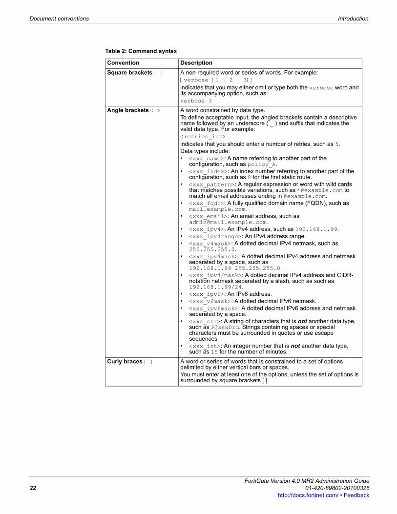
Typographical conventionsFortinet documentation uses the following typographical conventions:
* For conventions used to represent command syntax, see “CLI command syntax” on page 21.
CLI command syntax This guide uses the following conventions to describe syntax to use when entering commands in the Command Line Interface (CLI).Brackets, braces, and pipes are used to denote valid permutations of the syntax. Constraint notations, such as <address_ipv4>, indicate which data types or string patterns are acceptable value input.For more information, see the FortiGate CLI Reference.
Note: Presents useful information, usually focused on an alternative, optional method, such as a shortcut, to perform a step.
Tip: Highlights useful additional information, often tailored to your workplace activity.
Table 1: Typographical conventions in Fortinet technical documentation
Convention ExampleButton, menu, text box, field, or check box label
From Minimum log level, select Notification.
CLI input* config system dnsset primary <address_ipv4>
end
CLI output FGT-602803030703 # get system settingscomments : (null)opmode : nat
Emphasis HTTP connections are not secure and can be intercepted by a third party.
File content <HTML><HEAD><TITLE>Firewall Authentication</TITLE></HEAD><BODY><H4>You must authenticate to use this service.</H4>
Hyperlink Visit the Fortinet Technical Support web site, https://support.fortinet.com.
Keyboard entry Type a name for the remote VPN peer or client, such as Central_Office_1.
Navigation Go to VPN > IPSEC > Auto Key (IKE).
Publication For more information, see the FortiGate Administration Guide.Note: Links typically go to the most recent version. To access earlier releases, go to http://docs.fortinet.com/. This link appears at the bottom of each page of this document.
ortiGate Version 4.0 MR2 Administration Guide1-420-89802-20100326 21ttp://docs.fortinet.com/ • Feedback
Document conventions Introduction
Table 2: Command syntax
Convention DescriptionSquare brackets [ ] A non-required word or series of words. For example:
[verbose {1 | 2 | 3}]indicates that you may either omit or type both the verbose word and its accompanying option, such as:verbose 3
Angle brackets < > A word constrained by data type.To define acceptable input, the angled brackets contain a descriptive name followed by an underscore ( _ ) and suffix that indicates the valid data type. For example:<retries_int>indicates that you should enter a number of retries, such as 5.Data types include:• <xxx_name>: A name referring to another part of the
configuration, such as policy_A.• <xxx_index>: An index number referring to another part of the
configuration, such as 0 for the first static route.• <xxx_pattern>: A regular expression or word with wild cards
that matches possible variations, such as *@example.com to match all email addresses ending in @example.com.
• <xxx_fqdn>: A fully qualified domain name (FQDN), such as mail.example.com.
• <xxx_email>: An email address, such as [email protected].
• <xxx_ipv4>: An IPv4 address, such as 192.168.1.99.• <xxx_ipv4range>: An IPv4 address range.• <xxx_v4mask>: A dotted decimal IPv4 netmask, such as
255.255.255.0.• <xxx_ipv4mask>: A dotted decimal IPv4 address and netmask
separated by a space, such as 192.168.1.99 255.255.255.0.
• <xxx_ipv4/mask>: A dotted decimal IPv4 address and CIDR-notation netmask separated by a slash, such as such as 192.168.1.99/24.
• <xxx_ipv6>: An IPv6 address.• <xxx_v6mask>: A dotted decimal IPv6 netmask.• <xxx_ipv6mask>: A dotted decimal IPv6 address and netmask
separated by a space.• <xxx_str>: A string of characters that is not another data type,
such as P@ssw0rd. Strings containing spaces or special characters must be surrounded in quotes or use escape sequences
• <xxx_int>: An integer number that is not another data type, such as 15 for the number of minutes.
Curly braces { } A word or series of words that is constrained to a set of options delimited by either vertical bars or spaces.You must enter at least one of the options, unless the set of options is surrounded by square brackets [ ].
FortiGate Version 4.0 MR2 Administration Guide22 01-420-89802-20100326
http://docs.fortinet.com/ • Feedback

Introduction Registering your Fortinet product
F0h
Registering your Fortinet productBefore you begin configuring and customizing features, take a moment to register your Fortinet product at the Fortinet Technical Support web site, https://support.fortinet.com.Many Fortinet customer services, such as firmware updates, technical support, and FortiGuard Antivirus and other FortiGuard services, require product registration.For more information, see the Fortinet Knowledge Base article Registration Frequently Asked Questions.
Fortinet products End User License AgreementSee the Fortinet products End User License Agreement.
Customer service and technical supportFortinet Technical Support provides services designed to make sure that you can install your Fortinet products quickly, configure them easily, and operate them reliably in your network. To learn about the technical support services that Fortinet provides, visit the Fortinet Technical Support web site at https://support.fortinet.com.You can dramatically improve the time that it takes to resolve your technical support ticket by providing your configuration file, a network diagram, and other specific information. For a list of required information, see the Fortinet Knowledge Base article FortiGate Troubleshooting Guide - Technical Support Requirements.
TrainingFortinet Training Services provides a variety of training programs to serve the needs of our customers and partners world-wide. Visit the Fortinet Training Services web site at http://campus.training.fortinet.com, or email [email protected].
Options delimited by vertical bars |
Mutually exclusive options. For example:{enable | disable}indicates that you must enter either enable or disable, but must not enter both.
Options delimited by spaces
Non-mutually exclusive options. For example:{http https ping snmp ssh telnet}indicates that you may enter all or a subset of those options, in any order, in a space-delimited list, such as:ping https sshNote: To change the options, you must re-type the entire list. For example, to add snmp to the previous example, you would type:ping https snmp sshIf the option adds to or subtracts from the existing list of options, instead of replacing it, or if the list is comma-delimited, the exception will be noted.
Table 2: Command syntax
ortiGate Version 4.0 MR2 Administration Guide1-420-89802-20100326 23ttp://docs.fortinet.com/ • Feedback
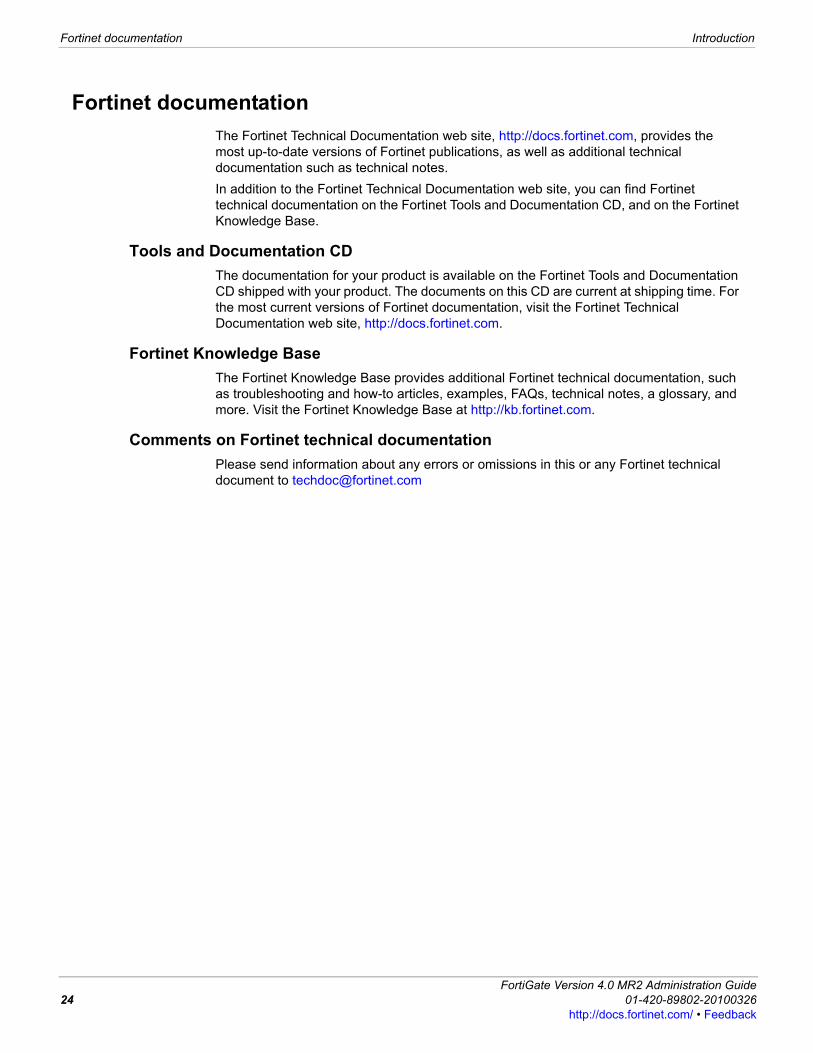
Fortinet documentation Introduction
Fortinet documentation The Fortinet Technical Documentation web site, http://docs.fortinet.com, provides the most up-to-date versions of Fortinet publications, as well as additional technical documentation such as technical notes.In addition to the Fortinet Technical Documentation web site, you can find Fortinet technical documentation on the Fortinet Tools and Documentation CD, and on the Fortinet Knowledge Base.
Tools and Documentation CDThe documentation for your product is available on the Fortinet Tools and Documentation CD shipped with your product. The documents on this CD are current at shipping time. For the most current versions of Fortinet documentation, visit the Fortinet Technical Documentation web site, http://docs.fortinet.com.
Fortinet Knowledge Base The Fortinet Knowledge Base provides additional Fortinet technical documentation, such as troubleshooting and how-to articles, examples, FAQs, technical notes, a glossary, and more. Visit the Fortinet Knowledge Base at http://kb.fortinet.com.
Comments on Fortinet technical documentation Please send information about any errors or omissions in this or any Fortinet technical document to [email protected]
FortiGate Version 4.0 MR2 Administration Guide24 01-420-89802-20100326
http://docs.fortinet.com/ • Feedback
Web-based manager Common web-based manager tasks
F0h
Web-based managerThis section describes the features of the user-friendly web-based manager administrative interface (sometimes referred to as a graphical user interface, or GUI) of your FortiGate unit. Using HTTP or a secure HTTPS connection from any management computer running a web browser, you can connect to the FortiGate web-based manager to configure and manage the FortiGate unit. The recommended minimum screen resolution for the management computer is 1280 by 1024. Some of the information displayed by the web-based manager uses features only supported by the most recent versions most popular web browsers. Older versions of these web browsers may not always work correctly with the web-based manager.You can configure the FortiGate unit for HTTP and HTTPS web-based administration from any FortiGate interface. To connect to the web-based manager you require a FortiGate administrator account and password. The web-based manager supports multiple languages, but by default appears in English on first use. You can go to System > Dashboard > Status to view detailed information about the status of your FortiGate unit on the system dashboard. The dashboard displays information such as the current FortiOS firmware version, antivirus and IPS definition versions, operation mode, connected interfaces, and system resources. It also shows whether the FortiGate unit is connected to a FortiAnalyzer unit and a FortiManager unit or other central management services.You can use the web-based manager menus, lists, and configuration pages to configure most FortiGate settings. Configuration changes made using the web-based manager take effect immediately without resetting the FortiGate unit or interrupting service. You can back up your configuration at any time using the Backup Configuration button on the button bar. The button bar is located in the upper right corner of the web-based manager. The saved configuration can be restored at any time.The web-based manager also includes detailed context-sensitive online help. Selecting Online Help on the button bar displays help for the current web-based manager page.You can use the FortiGate command line interface (CLI) to configure the FortiGate same settings that you can configure from the web-based manager, as well as additional CLI-only settings. The system dashboard provides an easy entry point to the CLI console that you can use without exiting the web-based manager.The following topics are included in this section:• Common web-based manager tasks• Using FortiGate Online Help• Web-based manager pagesWeb-based manager pages
Common web-based manager tasksThis section describes the following common web-based manager tasks:• Connecting to the web-based manager• Modifying current settings• Changing your FortiGate administrator password
ortiGate Version 4.0 MR2 Administration Guide1-420-89802-20100326 25ttp://docs.fortinet.com/ • Feedback
Common web-based manager tasks Web-based manager
• Changing the web-based manager language• Changing administrative access to your FortiGate unit• Changing the web-based manager idle timeout• Switching VDOMs• Connecting to the FortiGate CLI from the web-based manager• Contacting Customer Support
Connecting to the web-based managerTo connect to the web-based manager, you require: • a FortiGate unit connected to your network according to the instructions in the
QuickStart Guide and Install Guide for your FortiGate unit• the IP address of a FortiGate interface that you can connect to• a computer with an Ethernet connection to a network that can connect to the FortiGate
unit• a supported web browser. See the Knowledge Base articles Microsoft Windows WEB
browsers supported by Fortinet products web-based manager (GUI) web browsers and Mac OS browsers for use with Fortinet hardware web-based manager (GUI).
To connect to the web-based manager1 Start your web browser and browse to https:// followed by the IP address of the
FortiGate unit interface that you can connect to.For example, if the IP address is 192.168.1.99, browse to https://192.168.1.99. (remember to include the “s” in https://).To support a secure HTTPS authentication method, the FortiGate unit ships with a self-signed security certificate, which is offered to remote clients whenever they initiate a HTTPS connection to the FortiGate unit. When you connect, the FortiGate unit displays two security warnings in a browser.The first warning prompts you to accept and optionally install the FortiGate unit’s self-signed security certificate. If you do not accept the certificate, the FortiGate unit refuses the connection. If you accept the certificate, the login page appears. The credentials entered are encrypted before they are sent to the FortiGate unit. If you choose to accept the certificate permanently, the warning is not displayed again.Just before the login page is displayed, a second warning informs you that the FortiGate certificate distinguished name differs from the original request. This warning occurs because the FortiGate unit redirects the connection. This is an informational message. Select OK to continue logging in.
2 Type admin or the name of a configured administrator in the Name field.3 Type the password for the administrator account in the Password field.4 Select Login.
Modifying current settingsWhen you are modifying current settings, such as changing an administrator’s password, you must highlight the item and then select the applicable icon because all available icons are inaccessible otherwise. This way of accessing icons is explained in the following procedure. Use the procedure “To access icons for modifying items within a list” on page 27 whenever you are modifying current settings.
FortiGate Version 4.0 MR2 Administration Guide26 01-420-89802-20100326
http://docs.fortinet.com/ • Feedback
Web-based manager Common web-based manager tasks
F0h
To access icons for modifying items within a list1 In the Check box column, within the row of the setting you want to change, select the
check box to highlight the row. The grayed icons are now accessible. On some pages, all icons may not be accessible when you highlight the row.
2 With the icon or icons now accessible, select the icon that you want to use to make modifications with (such as the Edit icon). After the modifications are made, and you are back to the list on the page, the check box is unselected and the row unhighlighted.
Changing your FortiGate administrator passwordBy default, you can log into the web-based manager by using the admin administrator account and no password. You should add a password to the admin administrator account to prevent anybody from logging into the FortiGate and changing configuration options. For improved security, you should regularly change the admin administrator account password and the passwords for any other administrator accounts that you add.To change an administrator’s password, go to System > Admin > Administrators, enable access the Edit icon, and then change the password. Select OK to save the new password. You can also add new administrator accounts by selecting Create New. For more information about adding administrators, changing administrator account passwords and related configuration settings, see “System Admin” on page 167
Changing the web-based manager languageYou can change the web-based manager to display language in English, Simplified Chinese, Japanese, Korean, Spanish, Traditional Chinese, or French. For best results, you should select the language that the management computer operating system uses.To change the language, go to System > Admin > Settings, and under Display Settings, select the language you want from the Language drop-down list, and select Apply. The web-based manager pages display the chosen language.
Changing administrative access to your FortiGate unitThrough administrative access an administrator can connect to the FortiGate unit to view and change configuration settings. The default configuration of your FortiGate unit allows administrative access to one or more of the interfaces of the unit as described in your FortiGate unit QuickStart Guide and Install Guide.You can change administrative access by:• enabling or disabling administrative access from any FortiGate interface• enabling or disabling securing HTTPS administrative access to the web-based
manager (recommended)• enabling or disabling HTTP administrative access to the web-based manager (not
recommended)• enabling or disabling secure SSH administrative access to the CLI (recommended)
Note: If you forget or lose an administrator account password and cannot log into your FortiGate unit, see the Fortinet Knowledge Base article Recovering a lost FortiGate administrator account password.
ortiGate Version 4.0 MR2 Administration Guide1-420-89802-20100326 27ttp://docs.fortinet.com/ • Feedback
Common web-based manager tasks Web-based manager
• enabling or disabling SSH or Telnet administrative access to the CLI (not recommended).
To change administrative access, go to System > Network > Interface, access the Edit icon, and select the administrative access type or types for that interface. Select OK to save the changes.For more information about changing administrative access see “Configuring administrative access to an interface” on page 101.
Changing the web-based manager idle timeoutBy default, the web-based manager disconnects administrative sessions if no activity takes place for five minutes. This idle timeout is recommended to prevent someone from using the web-based manager from a PC that is logged into the web-based manager and then left unattended. However, you can use the following steps to change this idle timeout.To change the idle timeout, go to System > Admin > Settings, and under Idle Timeout enter the time in minutes, and then select Apply to save the changes.
Switching VDOMs When VDOMs are enabled, a menu appears in the left column called Current VDOM. This menu displays a drop-down list beside it. The drop-down list contains all the configured VDOMs on that FortiGate unit. This provides an easy, quick way to access a VDOM. To switch to a VDOM using the Current VDOM menu, select the VDOM that you want to switch to from the drop-down list beside Current VDOM. You are automatically redirected to that VDOM.
Connecting to the FortiGate CLI from the web-based managerYou can connect to the FortiGate CLI from the web-based manager dashboard by using the CLI console widget. You can use the CLI to configure all configuration options available from the web-based manager. Some configuration options are available only from the CLI. As well, you can use the CLI to enter diagnose commands and perform other advanced operations that are not available from the web-based manager. For more information about the FortiGate CLI see the FortiGate CLI Reference.To connect to the CLI console, go to System > Dashboard > Status, and in the CLI Console widget select inside the window. You are automatically logged in to the CLI. For more information, see “CLI Console” on page 50.
Contacting Customer SupportThe Contact Customer Support button opens the Fortinet Support web page in a new browser window. From this page you can:• visit the Fortinet Knowledge Base• log into Customer Support (Support Login)• register your Fortinet product (Product Registration)• view Fortinet Product End of Life information• find out about Fortinet Training and Certification• visit the FortiGuard Center.You must register your Fortinet product to receive product updates, technical support, and FortiGuard services. To register a Fortinet product, go to Product Registration and follow the instructions.
FortiGate Version 4.0 MR2 Administration Guide28 01-420-89802-20100326
http://docs.fortinet.com/ • Feedback

Web-based manager Using FortiGate Online Help
F0h
Using FortiGate Online HelpThe Online Help button displays context-sensitive online help for the current web-based manager page. The online help page that is displayed is called a content pane and contains information and procedures related to the current web-based manager page. Most help pages also contain hyperlinks to related topics. The online help system also includes a number of links that you can use to find additional information.FortiGate context-sensitive online help topics also include a VDOM or Global icon to indicate whether the web-based manager page is for VDOM-specific or global configuration settings. VDOM and Global configuration settings apply only to a FortiGate unit operating with virtual domains enabled. If you are not operating your FortiGate unit with virtual domains enabled, you can ignore the VDOM and Global icons. For more information about virtual domains, see “Using virtual domains” on page 73.
Figure 1: A context-sensitive online help page (content pane only)
To view the online help table of contents or index, and to use the search feature, select Online Help in the button bar in the upper right corner of the web-based manager. From the online help, select Show Navigation.
Show Navigation Open the online help navigation pane. From the navigation pane you can use the online help table of contents, index, and search to access all of the information in the online help. The online help is organized in the same way as the FortiGate web-based manager and the FortiGate Administration Guide.
Previous Display the previous page in the online help.
Next Display the next page in the online help
Email Send an email to Fortinet Technical Documentation at [email protected] if you have comments on or corrections for the online help or any other Fortinet technical documentation product.
Print Print the current online help page.
Bookmark Add an entry for this online help page to your browser bookmarks or favorites list to make it easier to find useful online help pages. Not supported by all browsers.
Show Navigation
EmailPrevious
NextPrintBookmark
ortiGate Version 4.0 MR2 Administration Guide1-420-89802-20100326 29ttp://docs.fortinet.com/ • Feedback
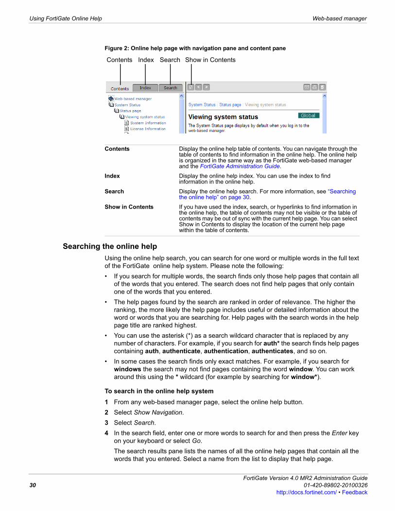
Using FortiGate Online Help Web-based manager
Figure 2: Online help page with navigation pane and content pane
Searching the online helpUsing the online help search, you can search for one word or multiple words in the full text of the FortiGate online help system. Please note the following:• If you search for multiple words, the search finds only those help pages that contain all
of the words that you entered. The search does not find help pages that only contain one of the words that you entered.
• The help pages found by the search are ranked in order of relevance. The higher the ranking, the more likely the help page includes useful or detailed information about the word or words that you are searching for. Help pages with the search words in the help page title are ranked highest.
• You can use the asterisk (*) as a search wildcard character that is replaced by any number of characters. For example, if you search for auth* the search finds help pages containing auth, authenticate, authentication, authenticates, and so on.
• In some cases the search finds only exact matches. For example, if you search for windows the search may not find pages containing the word window. You can work around this using the * wildcard (for example by searching for window*).
To search in the online help system1 From any web-based manager page, select the online help button.2 Select Show Navigation.3 Select Search.4 In the search field, enter one or more words to search for and then press the Enter key
on your keyboard or select Go. The search results pane lists the names of all the online help pages that contain all the words that you entered. Select a name from the list to display that help page.
Contents Display the online help table of contents. You can navigate through the table of contents to find information in the online help. The online help is organized in the same way as the FortiGate web-based manager and the FortiGate Administration Guide.
Index Display the online help index. You can use the index to find information in the online help.
Search Display the online help search. For more information, see “Searching the online help” on page 30.
Show in Contents If you have used the index, search, or hyperlinks to find information in the online help, the table of contents may not be visible or the table of contents may be out of sync with the current help page. You can select Show in Contents to display the location of the current help page within the table of contents.
Contents SearchIndex Show in Contents
FortiGate Version 4.0 MR2 Administration Guide30 01-420-89802-20100326
http://docs.fortinet.com/ • Feedback
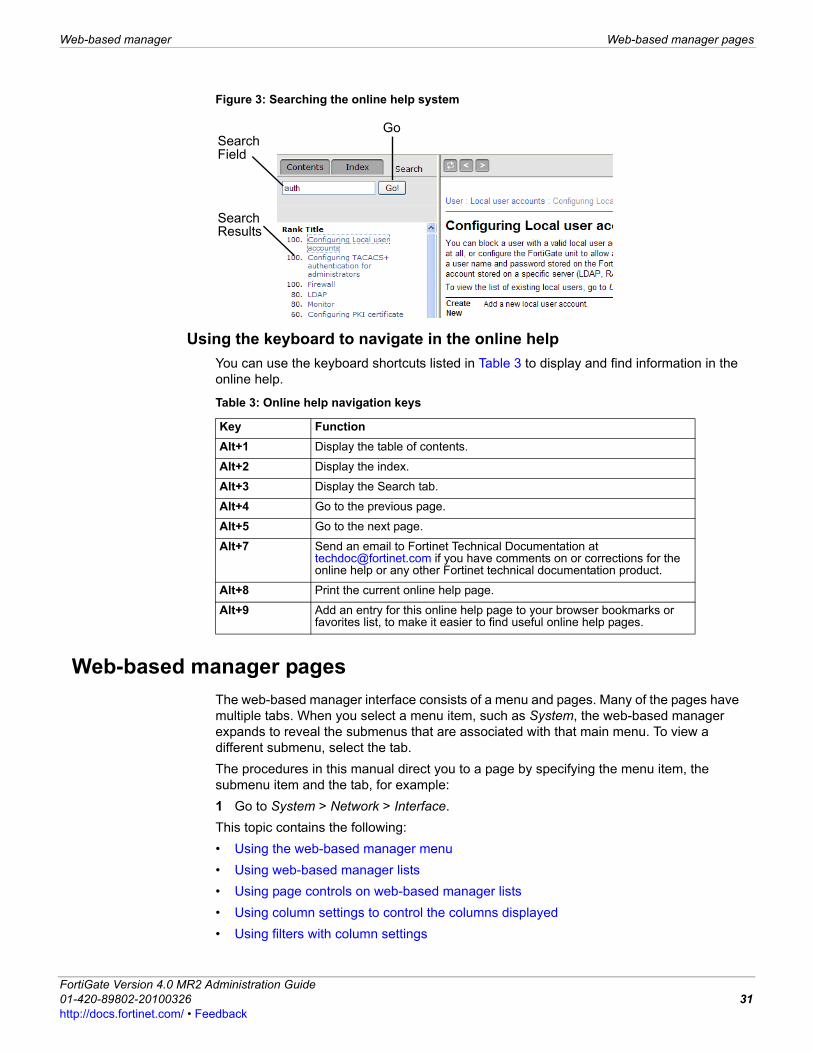
Web-based manager Web-based manager pages
F0h
Figure 3: Searching the online help system
Using the keyboard to navigate in the online helpYou can use the keyboard shortcuts listed in Table 3 to display and find information in the online help.
Web-based manager pagesThe web-based manager interface consists of a menu and pages. Many of the pages have multiple tabs. When you select a menu item, such as System, the web-based manager expands to reveal the submenus that are associated with that main menu. To view a different submenu, select the tab.The procedures in this manual direct you to a page by specifying the menu item, the submenu item and the tab, for example:1 Go to System > Network > Interface.This topic contains the following:• Using the web-based manager menu• Using web-based manager lists• Using page controls on web-based manager lists• Using column settings to control the columns displayed• Using filters with column settings
SearchField
Go
SearchResults
Table 3: Online help navigation keys
Key FunctionAlt+1 Display the table of contents.
Alt+2 Display the index.
Alt+3 Display the Search tab.
Alt+4 Go to the previous page.
Alt+5 Go to the next page.
Alt+7 Send an email to Fortinet Technical Documentation at [email protected] if you have comments on or corrections for the online help or any other Fortinet technical documentation product.
Alt+8 Print the current online help page.
Alt+9 Add an entry for this online help page to your browser bookmarks or favorites list, to make it easier to find useful online help pages.
ortiGate Version 4.0 MR2 Administration Guide1-420-89802-20100326 31ttp://docs.fortinet.com/ • Feedback

Web-based manager pages Web-based manager
Using the web-based manager menuThe web-based manager menu provides access to configuration options for all major FortiGate features (see Figure on page 31).
Using web-based manager listsMany of the web-based manager pages contain lists. There are lists of network interfaces, firewall policies, administrators, users, and others.If you log in as an administrator with an admin profile that allows Read-Write access to a list, depending on the list you will usually be able to:• Select Create New to add a new item to the list.• Modify and/or change the settings of an item in the list on a page• Remove an item from the list. The delete icon will not be available if the item cannot be
deleted. Usually items cannot be deleted if they have been added to another configuration; you must first find the configuration settings that the item has been added to and remove the item from them. For example, to delete a user that has been added to a user group you must first remove the user from the user group (see Figure ).
If you log in as an administrator with an admin profile that allows Read Only access to a list, you will only be able to view the items on the list (see Figure ).For more information, see “Admin profiles” on page 178.
System Configure system settings, such as network interfaces, virtual domains, DHCP services, administrators, certificates, High Availability (HA), system time and set system options.
Router Configure FortiGate static and dynamic routing and view the router monitor.
Firewall Configure firewall policies and protection profiles that apply network protection features. Also configure virtual IP addresses and IP pools.
UTM Configure antivirus and antispam protection, web filtering, intrusion protection, data leak prevention, and application control.
VPN Configure IPSec and SSL virtual private networking. PPTP is configured in the CLI.
User Configure user accounts for use with firewall policies that require user authentication. Also configure external authentication servers such as RADIUS, LDAP, TACACS+, and Windows AD. Configure monitoring of Firewall, IPSec, SSL, IM, and Banned Users.
Endpoint Configure end points, view FortiClient configuration information, and configure software detection patterns.
WAN Opt. & Cache Configure WAN optimization and web caching to improve performance and security of traffic passing between locations on your wide area network (WAN) or from the Internet to your web servers.
Wireless Controller Configure a FortiGate unit to act as a wireless network controller, managing the wireless Access Point (AP) functionality of FortiWiFi units.
Log&Report Configure logging and alert email. View log messages and reports.
Current VDOM Appears only when VDOMs are enabled on the FortiGate unit. Allows you to quickly switch between VDOMs. To switch between VDOMs, select a VDOM from the drop-down list that is beside Current VDOM.
FortiGate Version 4.0 MR2 Administration Guide32 01-420-89802-20100326
http://docs.fortinet.com/ • Feedback
Web-based manager Web-based manager pages
F0h
Adding filters to web-based manager listsYou can add filters to control the information that is displayed complex lists in the web-based manager. See the following web-based manager pages for examples of lists with filters:• Session list (see “Viewing the current sessions list” on page 52)• Firewall policy and IPv6 policy lists (see “Viewing the firewall policy list” on page 257,
“Viewing the DoS policy list” on page 268, and “Viewing the sniffer policy list” on page 272)
• Intrusion protection predefined signatures list (see “Viewing the predefined signature list” on page 531)
• Firewall user monitor list (see “Firewall user monitor list” on page 467)• IPSec VPN Monitor (see “Monitoring VPNs” on page 422)• Endpoint NAC list of known endpoints (see “Monitoring endpoints” on page 477)• Log and report log access list (see “Accessing and viewing log messages” on
page 497).Filters are useful for reducing the number of entries that are displayed on a list so that you can focus on the information that is important to you. For example, you can go to System > Dashboard > Status, and, in the Statistics section, select Details on the Sessions line to view the communications sessions that the FortiGate unit is currently processing. A busy FortiGate unit may be processing hundreds or thousands of communications sessions. You can add filters to make it easier to find specific sessions. For example, you might be looking for all communications sessions being accepted by a specific firewall policy. You can add a Policy ID filter to display only the sessions for a particular Policy ID or range of Policy IDs.You add filters to a web-based manager list by selecting any filter icon to display the Edit Filters window. From the Edit Filters window you can select any column name to filter, and configure the filter for that column. You can also add filters for one or more columns at a time. The filter icon remains gray for unfiltered columns and changes to green for filtered columns.The filter configuration is retained after leaving the web-based manager page and even after logging out of the web-based manager or rebooting the FortiGate unit.Different filter styles are available depending on the type of information displayed in individual columns. In all cases, you configure filters by specifying what to filter on and whether to display information that matches the filter, or by selecting NOT to display information that does not match the filter. On firewall policy, IPv6 policy, predefined signature and log and report log access lists, you can combine filters with column settings to provide even more control of the information displayed by the list. See “Using filters with column settings” on page 35 for more information.
Note: Filter settings are stored in the FortiGate configuration and will be maintained the next time that you access any list for which you have added filters.
ortiGate Version 4.0 MR2 Administration Guide1-420-89802-20100326 33ttp://docs.fortinet.com/ • Feedback
Web-based manager pages Web-based manager
Filters for columns that contain numbersIf the column includes numbers (for example, IP addresses, firewall policy IDs, or port numbers) you can filter by a single number or a range of numbers. For example, you could configure a source address column to display only entries for a single IP address or for all addresses in a range of addresses. To specify a range, separate the top and bottom values of the range with a hyphen, for example 25-50.To view the session list, go to System > Dashboard > Status. In the Statistics section, beside Sessions, select Details.
Filters for columns containing text stringsIf the column includes text strings (for example, names and log messages) you can filter by a text string. You can also filter information that is an exact match for the text string (equals), that contains the text string, or that does not equal or does not contain the text string. You can also specify whether to match the capitalization (case) of the text string. The text string can be blank and it can also be very long. The text string can also contain special characters such as <, &, > and so on. However, filtering ignores characters following a < unless the < is followed by a space (for example, filtering ignores <string but not < string). Filtering also ignores matched opening and closing < and > characters and any characters inside them (for example, filtering ignores <string> but does not ignore >string>).
Filters for columns that can contain only specific itemsFor columns that can contain only specific items (for example, a log message severity or a pre-defined signature action) you can select a single item from a list. In this case, you can only filter on a single selected item.
Custom filtersOther custom filters are also available. You can filter log messages according to date range and time range. You can also set the level filter to display log messages with multiple severity levels.
Using page controls on web-based manager listsThe web-based manager includes page controls to make it easier to view lists that contain more items than you can display on a typical browser window. Web-based manager pages with page controls include:• session list (see “Viewing the current sessions list” on page 52)• Router Monitor (see “Router Monitor” on page 259)• intrusion protection predefined signatures list (see “Viewing the predefined signature
list” on page 531)• web filtering lists (see “Web Filter” on page 547)• antispam lists (see “Email filtering” on page 567)• Firewall user monitor list (see “Firewall user monitor list” on page 467)• IPSec VPN Monitor (see “Monitoring VPNs” on page 422)• Banned user list (see “NAC quarantine and the Banned User list” on page 468)• log and report log access lists (see “Accessing and viewing log messages” on
page 497).• Endpoint NAC list of known endpoints (see “Monitoring endpoints” on page 477)
FortiGate Version 4.0 MR2 Administration Guide34 01-420-89802-20100326
http://docs.fortinet.com/ • Feedback
Web-based manager Web-based manager pages
F0h
Using column settings to control the columns displayedUsing column settings, you can format some web-based manager lists so that information that is important to you is easy to find and less important information is hidden or less distracting.On web-based manager pages that contain complex lists, you can change column settings to control the information columns that are displayed for the list and to control the order in which they are displayed. Web-based manager pages with column settings controls include:• Network interface list (see “Configuring interfaces” on page 89)• Firewall policy and IPv6 policy (see “Viewing the firewall policy list” on page 257)• Intrusion protection predefined signatures list (see “Viewing the predefined signature
list” on page 531)• Firewall user monitor list (see “Firewall user monitor list” on page 467)• IPSec VPN Monitor (see “Monitoring VPNs” on page 422)• Endpoint NAC list of known endpoints (see “Monitoring endpoints” on page 477)• Log and report log access lists (see “Accessing and viewing log messages” on
page 497).
To change column settings on a list that supports it, select Column Settings. From Available fields, select the column headings to be displayed and then select the Right Arrow to move them to the “Show these fields in this order” list. Similarly, to hide column headings, use the Left Arrow to move them back to the Available fields list. Use Move Up and Move Down to change the order in which to display the columns.For example, you can change interface list column headings to display only the IP/Netmask, MAC address, MTU, and interface Type for each interface.
Using filters with column settingsOn firewall policy, IPv6 policy, predefined signature, firewall user monitor, IPSec monitor and log and report log access lists you can combine filters with column settings to provide even more control of the information displayed by the list.
First Page Display the first page of items in the list.
Previous Page Display the previous page of items in the list.
Current Page The current page number of list items that are displayed. You can enter a page number and press Enter to display the items on that page. For example if there are 5 pages of items and you enter 3, page 3 of the sessions will be displayed.
Total Number of Pages The number of pages of list items that you can view.
Next Page Display the next page of items in the list.
Last Page Display the last page of items in the list.
Note: Any changes that you make to the column settings of a list are stored in the FortiGate configuration and will display the next time that you access the list.
ortiGate Version 4.0 MR2 Administration Guide1-420-89802-20100326 35ttp://docs.fortinet.com/ • Feedback
Web-based manager pages Web-based manager
For example, you can go to Intrusion Protection > Signature > Predefined and configure the Intrusion Protection predefined signatures list to show only the names of signatures that protect against vulnerabilities for a selected application. To do this, set Column Settings to only display Applications and Name. Then apply a filter to Applications so that only selected applications are listed. In the pre-defined signatures list you can also sort the list by different columns; you might want to sort the list by application so that all signatures for each application are grouped together.For more information, see “Adding filters to web-based manager lists” on page 33.
FortiGate Version 4.0 MR2 Administration Guide36 01-420-89802-20100326
http://docs.fortinet.com/ • Feedback
System Dashboard
System DashboardThis section describes the System Dashboard and its pages, Status and Usage. At a glance, you can view the current system status of the FortiGate unit including serial number, uptime, FortiGuard™ license information, system resource usage, alert messages and network statistics.If you enable virtual domains (VDOMs) on the FortiGate unit, the status page is available globally and system status settings are configured globally for the entire FortiGate unit. The Topology viewer is not available when VDOMs are enabled. For more information, see “Using virtual domains” on page 73.This section includes the following topics:• Dashboard overview• System Information• License Information• Unit Operation• System Resources• Alert Message Console• Log and Archive Statistics• CLI Console• Top Sessions• Top Viruses• Top Attacks• Traffic History• Top Policy Usage• DLP Archive Usage• RAID monitor• Top Application Usage• Disk Status• P2P Usage• Per-IP Bandwidth Usage• VoIP Usage• IM Usage• FortiGuard
Note: Your browser must support Java script to view the System Dashboard page.
The Topology Viewer is not included in FortiOS 4.0 MR2. If upgrading to FortiOS 4.0 MR2, all Topology Viewer configuration settings will be lost.
FortiGate Version 4.0 MR2 Administration Guide01-420-89802-20100326 37http://docs.fortinet.com/ • Feedback
Dashboard overview System Dashboard
38
Dashboard overview The Dashboard menu allows you to add and customize dashboards. Dashboards are menus that allow you to view information, such as traffic activity, from multiple widgets. This information is useful and can help you to update your firmware, reboot your FortiGate unit, or quickly view log and archive statistics. By adding and customizing dashboards, you can allow certain dashboards to contain specific information, such as log information, so that you can go directly to that dashboard to view that particular information. For example, the Archives dashboard (Dashboard > Archives) contains the DLP Archive Usage and Log and Archive Statistics widgets, allowing users to view only log archives information. Administrators must have read and write privileges to customize and add widgets when in either menu. Administrators must have read privileges if they want to view the information in Status and Usage. For more information about administrators and their profiles, see “Admin profiles” on page 178.This topic contains the following: • Adding widgets to a dashboard• Adding widgets to a dashboard• VDOM and global dashboards
Adding dashboardsDashboards are first added from the default menus, Status and Usage. You can add, remove or rename a dashboard, regardless of whether it is the Status or Usage menu. You can reset the Dashboard menu to its default settings by selecting Reset Dashboards.
To add a dashboard to the dashboard menu1 Go to Dashboard > Status. 2 Select the Dashboard icon. 3 A drop-down list appears with the following options:
4 Select Add Dashboard. 5 Enter a name for the dashboard in the Name field in the Add Dashboard window. 6 Select OK.
You are automatically redirected to the new dashboard. You can start adding widgets to the dashboard.
Adding widgets to a dashboardAfter adding a dashboard to the Dashboard menu, you can add multiple widgets to that dashboard. You can customize most widgets to display specific information, and with some widgets you can view more detailed information. To add a widget to a dashboard, select the Widget icon and then select a widget in the Click active module name to add module to the page window.
Add Dashboard Add a new dashboard to the Dashboard menu.
Rename Dashboard Rename the current dashboard. You can rename the existing default menus Status and Usage.
Delete Dashboard Removes the current dashboard that you are viewing.
Reset Dashboards Resets the entire Dashboard menu back to its default settings.
FortiGate Version 4.0 MR2 Administration Guide01-420-89802-20100326
http://docs.fortinet.com/ • Feedback
System Dashboard System Information
VDOM and global dashboardsVDOM administrators can view and configure the VDOM-specific dashboard for their VDOM. From a VDOM go to System > Dashboard > Status to view the VDOM dashboard. The System Information, Unit Operation, System Resources, Log and Archive Status, CLI Console, Top Sessions, and Traffic History dashboard widgets are available in the VDOM dashboard. The available widgets differ from their global equivalents as follows:
Global administrators with the super_admin admin profile can view only the global dashboard.
System InformationGo to System > Dashboard > Status to find System Information. To add the System Information widget to the dashboard go to System > Dashboard > Status, select Add Content and select System Information from the list.
Available widget settings for customizing a widgetWidget Title Shows the name of the display
Open/Close arrow Select to open or close the display.
History Select to show an expanded set of data.Not available for all widgets.
Edit Select to change settings for the display.
Refresh Select to update the displayed information.
Close Select to close the display. You will be prompted to confirm the action.
Note: The information that appears on Status applies to the whole HA cluster, not just the primary unit. This includes information such as URLs visited, emails sent and received, and viruses caught.
System information Cannot enable/disable Virtual Domains. No listing of current administrators.
CLI Console User is logged into the current VDOM and cannot access global configurations.
Unit Operation Unit reboot and shutdown are not available.Cannot configure management service or FortiAnalyzer unit.No information about network ports.
Top Sessions Shows only sessions for this VDOM.
Traffic History Can select only interfaces or VLANs belonging to this VDOM.
Serial Number The serial number of the FortiGate unit. The serial number is specific to the FortiGate unit and does not change with firmware upgrades.
Uptime The time in days, hours, and minutes since the FortiGate unit was started.
System Time The current date and time according to the FortiGate unit’s internal clock. Select Change to change the time or configure the FortiGate unit to get the time from an NTP server. For more information, see “Configuring system time” on page 41.
FortiGate Version 4.0 MR2 Administration Guide01-420-89802-20100326 39http://docs.fortinet.com/ • Feedback
System Information System Dashboard
40
HA Status The status of high availability for this unit. Standalone indicates the unit is not operating in HA mode.Active-Passive or Active-Active indicate the unit is operating in HA mode.Select Configure to configure the HA status for this unit. For more information, see “HA” on page 135.
Host Name The host name of the current FortiGate unit. Select Change to change the host name. For more information, see “Changing the FortiGate unit host name” on page 41.If the FortiGate unit is in HA mode, this field is not displayed.
Cluster Name The name of the HA cluster for this FortiGate unit. For more information, see “HA” on page 135.The FortiGate unit must be operating in HA mode to display this field.
Cluster Members The FortiGate units in the HA cluster. Information displayed about each member includes host name, serial number, and whether the unit is a primary (master) or subordinate (slave) unit in the cluster. For more information, see “HA” on page 135.The FortiGate unit must be operating in HA mode with virtual domains disabled to display this field.
Virtual Cluster 1Virtual Cluster 2
The role of each FortiGate unit in virtual cluster 1 and virtual cluster 2. For more information, see “HA” on page 135.The FortiGate unit must be operating in HA mode with virtual domains enabled to display these fields.
Firmware Version The version of the current firmware installed on the FortiGate unit. The format for the firmware version is Select Update to change the firmware. For more information, see “Changing the FortiGate firmware” on page 42.
System Configuration
The time period of when the configuration file was backed up. You can select Backup to back up the current configuration; when you select Backup, you are automatically redirected to the Backup page. If you want to restore a configuration file, select Restore; when you select Restore, you are automatically redirected to the Restore page.
FortiClient Version The currently version of FortiClient uploaded to your FortiGate unit used for endpoint control. This field appears if you can upload a FortiClient image onto your FortiGate unit. For more information, see “Configuring FortiClient installer download and version enforcement” on page 475.
Operation Mode The operating mode of the current FortiGate unit. A FortiGate unit can operate in NAT mode or Transparent mode. Select Change to switch between NAT and Transparent mode. For more information, see “Changing the operation mode” on page 164If virtual domains are enabled, this field shows the operating mode of the current virtual domain. Each virtual domain can be operating in either NAT mode or Transparent mode.If virtual domains are enabled, the Global System Status dashboard does not include this field.
Virtual Domain Status of virtual domains on your FortiGate unit. Select Enable or Disable to change the status of virtual domains feature.If you enable or disable virtual domains, your session will be terminated and you will need to log in again. For more information, see “Using virtual domains” on page 73.
FortiGate Version 4.0 MR2 Administration Guide01-420-89802-20100326
http://docs.fortinet.com/ • Feedback

System Dashboard System Information
Configuring system timeThe FortiGate unit’s system time can be changed in the System Information widget. You can also view what time it is in the System Time area of the System Information widget. 1 Go to System > Dashboard > Status.2 In the System Information widget, select Change on the System Time line.3 Select the time zone and then either set the date and time manually or configure
synchronization with an NTP server.
Changing the FortiGate unit host nameThe FortiGate host name appears on the Status page and in the FortiGate CLI prompt. The host name is also used as the SNMP system name. For information about SNMP, see “SNMP” on page 140.The default host name is the FortiGate unit serial number. For example the serial number FGT8002805030003 is a FortiGate-800 unit.Administrators whose admin profiles permit system configuration write access can change the FortiGate unit host name. If the host name is longer than 16 characters, it will be displayed as being truncated and end with a “~”. The full host name will be displayed under System > Status > Dashboard, but the truncated host name will be displayed on the CLI and other places it is used. If the FortiGate unit is part of an HA cluster, you should use a unique host name to distinguish the unit from others in the cluster.
Current Administrators
The number of administrators currently logged into the FortiGate unit.Select Details to view more information about each administrator that is currently logged in. The additional information includes user name, type of connection, IP address from which they are connecting, and when they logged in.
Current User The name of the admin account that you have used to log into the FortiGate unit. If you are authenticated locally by password, not by PKI or remote authentication, you can select Change Password to change the password for this account. When you change the password you are logged out and must log back in with the new password. For more information, see “Changing an administrator account password” on page 170.
System Time The current FortiGate system date and time.
Refresh Update the display of the current FortiGate system date and time.
Time Zone Select the current FortiGate system time zone.
Automatically adjust clock for daylight saving changes
Select to automatically adjust the FortiGate system clock when your time zone changes between daylight saving time and standard time.
Set Time Select to set the FortiGate system date and time to the values you set in the Hour, Minute, Second, Year, Month and Day fields.
Synchronize with NTP Server
Select to use a Network Time Protocol (NTP) server to automatically set the system date and time. You must specify the server and synchronization interval.FortiGate units use NTP Version 4. No RFC is currently available for NTP version 4. The RCF for NTP Version 3 is RFC 1305. For more information about NTP see http://www.ntp.org.
Server Enter the IP address or domain name of an NTP server. To find an NTP server that you can use, see http://www.ntp.org.
Sync Interval Specify how often the FortiGate unit should synchronize its time with the NTP server. For example, a setting of 1440 minutes causes the FortiGate unit to synchronize its time once a day.
FortiGate Version 4.0 MR2 Administration Guide01-420-89802-20100326 41http://docs.fortinet.com/ • Feedback
License Information System Dashboard
42
To change the FortiGate unit host name1 Go to System > Dashboard > Status.2 In the Host Name field of the System Information section, select Change.3 In the New Name field, type a new host name.4 Select OK.
The new host name is displayed in the Host Name field and the CLI prompt. It is also added to the SNMP System Name.
Changing the FortiGate firmware
FortiGate administrators whose admin profiles permit maintenance read and write access can change the FortiGate firmware. Firmware images can be transferred from a number of sources including a local hard disk, a local USB disk, or the FortiGuard Network. Firmware changes either upgrade to a newer version or revert to an earlier version. Follow the appropriate procedure to change your firmware.For more information about using the USB disk, and the FortiGuard Network see “System Maintenance” on page 215. For more information about managing firmware, see “Firmware management practices” on page 61.When you select Upgrade (or Downgrade, if downgrading the firmware), you are automatically redirected to the Firmware Upgrade/Downgrade page.
License InformationLicense Information displays the status of your technical support contract and FortiGuard subscriptions. The FortiGate unit updates the license information status indicators automatically when attempting to connect to the FortiGuard Distribution Network (FDN). FortiGuard Subscriptions status indicators are green if the FDN was reachable and the license was valid during the last connection attempt, grey if the FortiGate unit cannot connect to the FDN, and orange if the FDN is reachable but the license has expired.
Caution: By installing an older firmware image, some system settings may be lost. You should always backup your configuration before changing the firmware image.
Firmware Upgrade/Downgrade pageProvides settings for upgrading or downgrading the firmware on your FortiGate unit.
Upgrade From Select the firmware source from the drop down list of available sources. Possible sources include Local Hard Disk, USB, and FortiGuard Network.This field does not appear on all models.
Upgrade File Browse to the location of the firmware image on your local hard disk. This field is available for local hard disk and USB only.
Allow Firmware Downgrade
Select to confirm the the installation of an older firmware image (downgrade). This field only displayed when attempting to downgrade firmware.
More Info Go to the FortiGuard Center to learn more about firmware updates through the FortiGuard network.
Note: To access firmware updates for your FortiGate model, you will need to register your FortiGate unit with Customer Support. For more information go to http://support.fortinet.com or contact Customer Support.
FortiGate Version 4.0 MR2 Administration Guide01-420-89802-20100326
http://docs.fortinet.com/ • Feedback
System Dashboard License Information
When a new FortiGate unit is powered on, it automatically searches for FortiGuard services. If the unit is configured for central management, it will look for FortiGuard services on the configured FortiManager system. The FortiGate unit sends its serial number to the FortiGuard service provider, which then determines whether the FortiGate unit is registered and has valid contracts for FortiGuard subscriptions and FortiCare support services. If the FortiGate unit is registered and has a valid contract, the License Information is updated. If the FortiGate unit is not registered, any administrator with the super_admin profile sees a reminder message that provides access to a registration form.When a contract is due to expire within 30 days, any administrator with the super_admin profile sees a notification message that provides access to an Add Contract form. Simply enter the new contract number and select Add. Fortinet Support also sends contract expiry reminders. Optionally, you can disable notification for registration or contract inquiry.
To disable registration notificationconfig system globalset registration-notification disable
end
To disable contract expiry notificationconfig system globalset service-expire-notification disable
end
Selecting any of the Configure options will take you to the Maintenance page. For more information, see “System Maintenance” on page 215.
Support Contract Displays details about your current Fortinet Support contract including expiry dates and registration status.• If Not Registered appears, select Register to register the unit.• If Expired appears, select Renew for information on renewing your
technical support contract. Contact your local reseller. • If Registered appears the name of the support that registered this
FortiGate unit is also displayed. • You can select Login Now to log into the Fortinet Support account that
registered this FortiGate unit.
FortiGuard ServicesAntiVirus The FortiGuard Antivirus version, license issue date and service status. If
your license has expired, you can select Renew to renew the license.
AV Definitions The currently installed version of the FortiGuard Antivirus definitions. To update the definitions manually, select Update. For more information, see “P2P Usage” on page 59.
Extended set The currently installed version of the extended FortiGuard Antivirus definitions. For more information about the extended antivirus database, see “Selecting the virus database” on page 527. To update the definitions manually, select Update. For more information, see “P2P Usage” on page 59. The extended antivirus database is not available on all models.
Intrusion Protection
The FortiGuard Intrusion Prevention System (IPS) license version, license issue date and service status. If your license has expired, you can select Renew to renew the license.
IPS Definitions The currently installed version of the IPS attack definitions. To update the definitions manually, select Update. For more information, see “P2P Usage” on page 59.
FortiGate Version 4.0 MR2 Administration Guide01-420-89802-20100326 43http://docs.fortinet.com/ • Feedback
License Information System Dashboard
44
Manually updating FortiGuard definitionsYou can update your FortiGuard antivirus database, Intrusion Protection definitions, and antispam rule set at any time from the License Information section of the System Status page.For information about configuring automatic FortiGuard updates, see “Configuring FortiGuard Services” on page 222.
To update FortiGuard antivirus definitions, IPS definitions, or antispam rule set manually1 Download the latest update file from Fortinet support site and copy it to the computer
that you use to connect to the web-based manager.2 Start the web-based manager and go to System > Dashboard > Status.3 In the License Information section, in the AV Definitions, IPS Definitions, or AS Rule
Set field of the FortiGuard Subscriptions, select Update.4 Select Browse and locate the update file or type the path and filename.5 Select OK to copy the update file to the FortiGate unit.
The FortiGate unit updates the AV definitions. This takes about 1 minute.6 Go to System > Dashboard > Status to confirm that the version information for the
selected definition or rule set has updated.
Web Filtering The FortiGuard Web Filtering license status, expiry date and service status. If your license has expired, you can select Renew to renew the license.
Email Filtering The FortiGuard Email Filtering or Antispam license status, license expiry date and service status. If your license has expired, you can select Renew to renew the license.
Email Filtering Rule Set
The currently installed version of the FortiGuard Email Filtering rule set. To update the rule set manually, select Update. For more information, see “P2P Usage” on page 59.
Analysis & Management Service
The FortiGuard Analysis Service and Management Service license, license expiry date, and reachability status. For more information, see “Configuring FortiGuard Analysis & Management Service Options” on page 227.
Services Account ID
Select Change to enter a different Service Account ID. This ID is used to validate your license for subscription services such as FortiGuard Management Service and FortiGuard Analysis Service. For more information, see “Configuring FortiGuard Analysis & Management Service Options” on page 227.
Virtual DomainVDOMs Allowed The maximum number of virtual domains the unit supports with the current
license.For high-end FortiGate models, you can select the Purchase More link to purchase a license key through Fortinet technical support to increase the maximum number of VDOMs. For more information, see “Adding VDOM Licenses” on page 233.
Endpoint SecurityFortiClient SoftwareWindows Installer
View information about the latest version of the FortiClient application available from FortiGuard for EndPoint NAC. Select Download to download the FortiClient application installer to your PC. For more information, see “Configuring FortiClient installer download and version enforcement” on page 475.
Application Signature package
The version number of the current endpoint NAC application detection predefined signature package. For more information, see “Configuring application sensors” on page 473.
FortiGate Version 4.0 MR2 Administration Guide01-420-89802-20100326
http://docs.fortinet.com/ • Feedback
System Dashboard Unit Operation
Unit Operation
In the Unit Operation widget, an illustration of the FortiGate unit’s front panel shows the status of the unit’s Ethernet network interfaces. If a network interface is green, that interface is connected. Pause the mouse pointer over the interface to view the name, IP address, netmask and current status of the interface.If you select Reboot or ShutDown, a pop-up window opens allowing you to enter the reason for the system event. Your reason will be added to the Disk Event Log if disk logging, event logging, and admin events are enabled. For more information on Event Logging, see “Accessing and viewing log messages” on page 497.You can only have one management and one logging/analyzing method displayed for your FortiGate unit. The graphic for each will change based on which method you choose. If none are selected, no graphic is shown.
Caution: Abruptly powering off your FortiGate unit may corrupt its configuration. Using the reboot and shutdown options here or in the CLI ensures proper shutdown procedures are followed to prevent any loss of configuration.
INT / EXT / DMZ / HA / WAN1 / WAN2 / 1 / 2 / 3 / 4
The network interfaces on the FortiGate unit. The names and number of these interfaces vary by model. The icon below the interface name indicates its up/down status by color. Green indicates the interface is connected. Grey indicates there is no connection.For more information about the configuration and status of an interface, pause the mouse over the icon for that interface. A tooltip displays the full name of the interface, its alias if one is configured, the IP address and netmask, the status of the link, the speed of the interface, and the number of sent and received packets.
AMC-SW1/1, ...AMC-DW1/1, ...
If your FortiGate unit supports Advanced Mezzanine Card (AMC) modules and if you have installed an AMC module containing network interfaces (for example, the ASM-FB4 contains 4 interfaces) these interfaces are added to the interface status display. The interfaces are named for the module, and the interface. For example AMC-SW1/3 is the third network interface on the SW1 module, and AMC-DW2/1 is the first network interface on the DW2 module.AMC modules support hard disks as well, such as the ASM-S08 module. When a hard disk is installed, ASM-S08 is visible as well as a horizontal bar and percentage indicating how full the hard disk is.You can also add the ASM-CX4 and ASM-FX2 modules to bridge FortiGate interfaces when the FortiGate unit is operating in transparent mode.For more information about AMC modules, see “AMC module configuration” on page 217.
FortiAnalyzer The icon on the link between the FortiGate unit graphic and the FortiAnalyzer graphic indicates the status of their OFTP connection. An ‘X’ on a red icon indicates there is no connection. A check mark on a green icon indicates there is OFTP communication. Select the FortiAnalyzer graphic to configure remote logging tot he FortiAnalyzer unit on your FortiGate unit. For more information, see “Remote logging to a FortiAnalyzer unit” on page 491.
FortiGuard Analysis Service
The icon on the link between the FortiGate unit graphic and the FortiGuard Analysis Service graphic indicates the status of their OFTP connection. An ‘X’ on a red icon indicates there is no connection. A check mark on a green icon indicates there is OFTP communication. Select the FortiGuard Analysis Service graphic to configure remote logging to the FortiGuard Analysis Service. For more information, see the FortiGuard Analysis and Management Service Administration Guide.
FortiGate Version 4.0 MR2 Administration Guide01-420-89802-20100326 45http://docs.fortinet.com/ • Feedback
System Resources System Dashboard
46
System ResourcesThe System Resources widget displays basic FortiGate unit resource usage, such as CPU and memory (RAM) usage. Any System Resources that are not displayed on the status page can be viewed as a graph by selecting the History icon. To see the most recent CPU and memory usage, select the Refresh icon.
Viewing operational historyThe System Resource History page displays six graphs representing different system resources and protection activity over time. If no units are displayed on the vertical axis of a graph, it is in percentage.
FortiManager The icon on the link between the FortiGate unit graphic and the FortiManager graphic indicates the status of the connection. An ‘X’ on a red icon indicates there is no connection. A check mark on a green icon indicates there is communication between the two units.Select the FortiManager graphic to configure central management on your FortiGate unit. For more information, see “Central Management” on page 182.
FortiGuard Management Service
The icon on the link between the FortiGate unit graphic and the FortiGuard Management Service graphic indicates the status of the connection. An ‘X’ on a red icon indicates there is no connection. A check mark on a green icon indicates there is communication. Select the FortiGuard Management Service graphic to configure central management on your FortiGate unit. For more information, see “Central Management” on page 182.
Reboot Select to shutdown and restart the FortiGate unit. You will be prompted to enter a reason for the reboot that will be entered into the logs.
Shutdown Select to shutdown the FortiGate unit. You will be prompted for confirmation, and also prompted to enter a reason for the shutdown that will be entered into the logs.
History A graphical representation of the last minute of CPU, memory, sessions, and network usage. This page also shows the virus and intrusion detections over the last 20 hours. For more information, see “Viewing operational history” on page 46.
CPU Usage The current CPU status displayed as a dial gauge and as a percentage. The web-based manager displays CPU usage for core processes only. CPU usage for management processes (for example, for HTTPS connections to the web-based manager) is excluded.The displayed CPU usage is equivalent to using the CLI command get system performance status and adding user, system, and nice percentages. Both the web-based CPU Usage and the CLI command access the same CPU information.
Memory Usage The current memory (RAM) status displayed as a dial gauge and as a percentage. The web-based manager displays memory usage for core processes only. Memory usage for management processes (for example, for HTTPS connections to the web-based manager) is excluded.
FortiAnalyzer Usage The current status of the FortiAnalyzer disk space used by this FortiGate unit’s quota, displayed as a pie chart and a percentage. You can use the System Resources edit menu to select not to display this information. This is available only if you have configured logging to a FortiAnalyzer unit.
Disk Usage The current status of the FortiGate unit disk space used, displayed as a pie chart and a percentage. This is available only if you have a hard disk on your FortiGate unit.
FortiGate Version 4.0 MR2 Administration Guide01-420-89802-20100326
http://docs.fortinet.com/ • Feedback
System Dashboard Alert Message Console
The refresh rate is 3 second intervals for the graphs.To view the operational history, go to System > Dashboard > Status , then select History in the upper right corner of the System Resources widget.
Alert Message ConsoleAlert messages help you track system events on your FortiGate unit such as firmware changes, network security events, or virus detection events.Each message shows the date and time that the event occurred.
The following types of messages can appear in the Alert Message Console:
You can configure the alert message console settings to control what types of messages are displayed on the console.
To configure the Alert Message Console1 Go to System > Dashboard > Status.
Time Interval Select the time interval to display along the bottom axis of the graphs.
CPU Usage History Percentage CPU usage for the preceding interval.
Memory Usage History Percentage memory usage for the preceding interval.
Session History Number of sessions over the preceding interval.
Network Utilization History Network utilization for the preceding interval.
Virus History Number of Viruses detected over the preceding interval.
Intrusion History Number of intrusion attempts detected over the preceding interval.
History View all alert messages.
Edit Configure Alert Message Console settings.
Refresh Update displayed information.
Close Close the module.
Acknowledge this message
Select to remove this message.The Acknowledge icon is also available for each alert message in the History window.
System restart The system restarted. The restart could be due to operator action or power off/on cycling.
System shutdown An administrator shut down the FortiGate unit from the web-based manager or CLI.
Firmware upgraded by <admin_name>
The named administrator upgraded the firmware to a more recent version on either the active or non-active partition.
Firmware downgraded by <admin_name>
The named administrator downgraded the firmware to an older version on either the active or non-active partition.
FortiGate has reached connection limit for <n> seconds
The antivirus engine was low on memory for the duration of time shown and entered conserve mode. Depending on model and configuration, content can be blocked or can pass unscanned under these conditions.
Found a new FortiAnalyzerLost the connection to FortiAnalyzer
Shows that the FortiGate unit has either found or lost the connection to a FortiAnalyzer unit. For more information, see “Remote logging to a FortiAnalyzer unit” on page 491.
New firmware is available from FortiGuard
An updated firmware image is available to be downloaded to this FortiGate unit.
FortiGate Version 4.0 MR2 Administration Guide01-420-89802-20100326 47http://docs.fortinet.com/ • Feedback
Log and Archive Statistics System Dashboard
48
2 Select the Edit icon in the Alert Message Console title bar.3 Select the types of alerts that the Alert Message Console should display.
By default, all alert types are enabled.4 Select OK.
Log and Archive StatisticsThe Log and Archive Statistics widget allows you to see at a glance what is happening on your FortiGate unit with regards to DLP archiving, network traffic, and security problems including attack attempts, viruses caught, and spam emails caught.You can quickly see the amount and type of traffic as well as any attack attempts on your system. To investigate an area that draws your attention, select Details for a detailed list of the most recent activity in that area.The information displayed in the Log and Archive Statistics widget is derived from log messages. You can use the information gathered by log messages to see trends in network activity or attacks over time. Various configuration settings are required to actually collect data for the Log and Archive Statistics widget as described below.
Since The date and time when the counts were last reset.Counts are reset when the FortiGate unit reboots, or when you select Reset.
Reset Reset the Log and Archive Statistic counts to zero.
DLP Archive A summary of the HTTP, HTTPS, email, FTP IM, and VoIP (also called session control) traffic that has passed through the FortiGate unit, and has been archived by DLP.The Details pages list the last items of the selected type—up to 64 items—and provides links to the FortiAnalyzer unit where the archived traffic is stored. If logging to a FortiAnalyzer unit is not configured, the Details pages provide a link to Log & Report > Log Config > Log Settings. You configure the FortiGate unit to collect DLP archive data for the widget by configuring a DLP sensor to archive its log data. For more information, see “DLP archiving” on page 371.
FortiGate Version 4.0 MR2 Administration Guide01-420-89802-20100326
http://docs.fortinet.com/ • Feedback

System Dashboard Log and Archive Statistics
Viewing DLP archive information on the Statistics widgetFrom the Statistics widget of the System Status page, you can view statistics about HTTP, HTTPS, FTP and IM traffic through the FortiGate unit. You can select the Details link beside each traffic type to view more information. You can select Reset on the header of the Statistics section to clear the DLP archive and attack log information, and reset the counts to zero.To view DLP archive information, go to the Statistics widget in System > Dashboard > Status, and select Details in the row. The following table explains what is seen when you select Details for each protocol.
You must also add the profile to a firewall policy. When the firewall policy receives sessions for the selected protocols, meta-data is added to the statistics widget.
The Email statistics are based on email protocols. POP3 and IMAP traffic is registered as email received, and SMTP is email sent. If your FortiGate unit supports SSL content scanning and inspection, incoming email also includes POP3S and IMAPS and outgoing email also includes SMTPS. If incoming or outgoing email does not use these protocols, these statistics will not be accurate. For more information about SSL content scanning and inspection, see the UTM chapter of the FortiOS Handbook. The IM statistics are based on the AIM, ICQ, MSN, and Yahoo! protocols and configured by selecting Archive in DLP Sensors for IM DLP rules.The VoIP statistics are based on the SIP, SIMPLE and SCCP session control protocols and configured by selecting Archive in DLP Sensors for Session Control DLP rules.
Log A summary of traffic, viruses, attacks, spam email messages, and blocked URLs that the FortiGate unit has logged. Also displays the number of sessions matched by DLP and event log messages. The Details pages list the 20 most recent items, providing the time, source, destination and other information. DLP data loss detected actually displays the number of sessions that have matched DLP sensor profiles. DLP collects meta-data about all sessions matched by DLP sensors and records this meta-data in the DLP log. Every time a DLP log message is recorded, the DLP data loss detected number increases. If you are using DLP for summary or full archiving the DLP data loss detected number can get very large. This number may not indicate that data has been lost or leaked.
Table 4: Viewing DLP archive information
HTTP Date and Time – The time when the URL was accessed.From – The IP address from which the URL was accessed.URL – The URL that was accessed.
Email Date and Time – The time that the email passed through the FortiGate unit.From – The sender’s email address.To – The recipient’s email address.Subject – The subject line of the email.
FTP Date and Time – The time of access.Destination – The IP address of the FTP server that was accessed.User – The User ID that logged into the FTP server.Downloads – The names of files that were downloaded.Uploads – The names of files that were uploaded.
IM Date / Time – The time of access.Protocol – The protocol used in this IM session.Kind – The kind of IM traffic this transaction is.Local – The local address for this transaction.Remote – The remote address for this transactionDirection – If the file was sent or received.
FortiGate Version 4.0 MR2 Administration Guide01-420-89802-20100326 49http://docs.fortinet.com/ • Feedback
CLI Console System Dashboard
50
Viewing the Attack LogFrom the Statistics section of the Status page, you can view statistics about the network attacks that the FortiGate unit has stopped. You can view statistics about viruses caught, attacks detected, spam email detected, and URLs blocked. You can also view information about sessions matched by DLP rules. You can select the Details link beside each attack type to view more information.You can select Reset on the header of the Statistics section to clear the DLP archive and attack log information and reset the counts to zero.To view Attack Log information, go to the Statistics widget in System > Dashboard > Status, and select Details in the row. The following table explains what is seen when you select Details for each protocol.
CLI ConsoleThe Status page can include a CLI console. To use the console, select it to automatically log in to the admin account you are currently using in the web-based manager. You can copy (CTRL-C) and paste (CTRL-V) text from or to the CLI Console.The two controls located on the CLI Console widget title bar are Customize, and Detach. Detach moves the CLI Console widget into a pop-up window that you can resize and reposition. The two controls on the detached CLI Console are Customize and Attach. Attach moves the CLI console widget back onto the System Status page. Customize allows you to change the appearance of the console by defining fonts and colors for the text and background.
Table 5: Viewing Attack Log information
AV Date and Time – The time when the virus was detected.From – The sender’s email address or IP address.To – The intended recipient’s email address or IP address.Service – The service type, such as POP or HTTP.Virus – The name of the virus that was detected.
IPS Date and Time – The time that the attack was detected.From – The source of the attack. To – The target host of the attack.Service – The service type.Attack – The type of attack that was detected and prevented.
Email Date and Time – The time that the spam was detected.From -> To IP – The sender and intended recipient IP addresses.From -> To Email Accounts – The sender and intended recipient email addresses.Service – The service type, such as SMTP, POP or IMAP.SPAM Type – The type of spam that was detected.
URLs Date and Time – The time that the attempt to access the URL was detected.From – The host that attempted to view the URL.URL Blocked – The URL that was blocked.
DLP Date and Time – The time that the attempt to access the URL was detected.Service – The service type, such as HTTP, SMTP, POP or IMAP.Source – The source address of the session.From – The host that attempted to view the URL.URL Blocked – The URL that was blocked.From – The sender’s email address or IP address.To – The intended recipient’s email address or IP address.
FortiGate Version 4.0 MR2 Administration Guide01-420-89802-20100326
http://docs.fortinet.com/ • Feedback
System Dashboard Top Sessions
Top SessionsTop Sessions displays either a bar graph or a table showing the IP addresses that have the most sessions currently open on the FortiGate unit. The sessions are sorted by their source or destination IP address, or the port address. The sort criteria being used is displayed in the top right corner. The Top Sessions widget polls the FortiGate unit for session information, and this slightly impacts the FortiGate unit performance. For this reason when this display is not shown on the dashboard, it is not collecting data, and not impacting system performance. When the display is shown, information is only stored in memory.
Select Details to view the current sessions list, a list of all sessions currently processed by the FortiGate unit. For more information, see “Viewing the current sessions list” on page 52.To view detailed information about the sessions represented by a bar in the chart, click on the bar. To change the information displayed on the Top Sessions widget, select the Edit icon and make the required changes.
Preview A preview of your changes to the CLI Console’s appearance.
Text Select the current color swatch next to this label, then select a color from the color palette to the right to change the color of the text in the CLI Console.
Background Select the current color swatch next to this label, then select a color from the color palette to the right to change the color of the background in the CLI Console.
Use external command input box
Select to display a command input field below the normal console emulation area. When this option is enabled, you can enter commands by typing them into either the console emulation area or the external command input field.
Console buffer length Enter the number of lines the console buffer keeps in memory. Valid numbers range from 20 to 9999.
Font Select a font from the list to change the display font of the CLI Console.
Size Select the size of the font. The default size is 10 points.
Note: Rebooting the FortiGate unit will reset the Top Session statistics to zero.
Sort Criteria Select the method used to sort the Top Sessions on the System Status display. Choose one of:• Source Address• Destination Address• Port Address
Display User Name Select to include the username associated with this source IP address, if available. In the table display format this will be a separate column.Display UserName is available only when the sort criteria is Source Address.
Resolve Host Name Select to resolve the IP address to the host name.Resolve Host Name is not available when the sort criteria is Destination Port.
FortiGate Version 4.0 MR2 Administration Guide01-420-89802-20100326 51http://docs.fortinet.com/ • Feedback
Top Sessions System Dashboard
52
Viewing the current sessions listThe current sessions list displays all sessions currently processed by the FortiGate unit. For each session the current session list displays:• the session protocol such as tcp or udp• source address and port• destination address and port• the ID of the policy, if any, that applies to the session• how long until the session expires• which virtual domain the session belongs to
Resolve Service Select to resolve a port addresses into their commonly associated service names. Any port address without a service, will continue to be displayed as the port address. For example port 443 would resolve to HTTPS.Resolve Service is only available when the sort criteria is Destination Port.
Display Format Select how the Top Session information is displayed. Choose one of: • Chart• Table
Top Sessions to Show
Select the number of sessions to display. Choose to display 5, 10, 15, or 20 sessions.
Refresh Interval Select how often the display is updated. The refresh interval range is from 10 to 240 seconds. Selecting 0 will disable the automatic refresh of the display. You will still be able to select the manual refresh option on the Top Sessions title bar.Shorter refresh intervals may impact the performance of your FortiGate unit. If this occurs, try increasing the refresh interval or disabling the automatic refresh.
Virtual Domain Select a virtual domain to list the sessions being processed by that virtual domain. Select All to view sessions being processed by all virtual domains. This is only available if virtual domains are enabled. For more information see “Using virtual domains” on page 73.
Refresh Update the session list.
First Page Select to go to the first displayed page of current sessions.
Previous Page Select to go to the page of sessions immediately before the current page
Page Enter the page number of the session to start the displayed session list. For example if there are 5 pages of sessions and you enter 3, page 3 of the sessions will be displayed. The number following the ‘/’ is the number of pages of sessions.
Next Page Select to go to the next page of sessions.
Last Page Select to go to the last displayed page of current sessions.
Total The total number sessions.
Clear All Filters Select to reset any display filters that may have been set.
Return Return to the Top Sessions display.
Filter Icon The icon at the top of all columns except #, and Expiry. When selected it brings up the Edit Filter dialog allowing you to set the display filters by column. See “Adding filters to web-based manager lists” on page 33.
Protocol The service protocol of the connection, for example, udp, tcp, or icmp.
Source Address The source IP address of the connection.
Source Port The source port of the connection.
Destination Address
The destination IP address of the connection.
FortiGate Version 4.0 MR2 Administration Guide01-420-89802-20100326
http://docs.fortinet.com/ • Feedback
System Dashboard Top Viruses
To view the current sessions list1 Go to System > Dashboard > Status.2 In the Top Sessions widget, select Details at the bottom of the widget.
The current sessions list appears. Optionally select Detach to detach and expand the browser window to see the entire list.
3 Select Return to return to the Top Sessions bar chart display.
Top VirusesTop Viruses displays a bar graph representing the virus threats that have been detected most frequently by the FortiGate unit.The Top Viruses display is not part of the default dashboard display. It can be displayed by selecting Add Content >Top Viruses from the drop down menu.If you select the history icon, a window opens that displays up to the 20 most recent viruses that have been detected with information including the virus name, when it was last detected, and how many times it was detected. The system stores up to 1024 entries, but only displays up to 20 in the web-based manager.You can configure several settings for this widget when you select the Edit icon in this widget’s title bar area. You must select OK to save the settings.
Top AttacksTop Attacks displays a bar graph representing the most numerous attacks detected by the FortiGate unit.The Top Attacks display is not part of the default dashboard display. It can be displayed by selecting Add Content > Top Attacks from the drop down menu.Selecting the history icon opens a window that displays up to the 20 most recent attacks that have been detected with information including the attack name, when it was last detected, and how many times it was detected. The FortiGate unit stores up to 1024 entries, but only displays up to 20 in the web-based manager.You can configure several settings for this widget when you select the Edit icon in this widget’s title bar area. You must select OK to save the settings.
Destination Port The destination port of the connection.
Policy ID The number of the firewall policy allowing this session or blank if the session involves only one FortiGate interface (admin session, for example).
Expiry (sec) The time, in seconds, before the connection expires.
Duration The age of each session in seconds. The age is the amount of time the session has been active.
Delete Stop an active communication session. Your admin profile must include read and write access to System Configuration.
Custom Top Viruses DisplayCustom Widget Name Enter a new name for the widget. This is optional.
Refresh Interval Select display update interval in seconds. Range 10 to 240 seconds. Select 0 to disable updating. You can also update using the Refresh icon in the module header.
Top Viruses To Show Select whether to display top 5, 10, 15, or 20 viruses.
FortiGate Version 4.0 MR2 Administration Guide01-420-89802-20100326 53http://docs.fortinet.com/ • Feedback
Traffic History System Dashboard
54
Traffic HistoryThe traffic history widget shows the traffic on one selected interface over the last hour, day, and month. This feature can help you locate peaks in traffic that you need to address as well as their frequency, duration, and other information. Only one interface at a time can be monitored. You can change the interface being monitored by selecting Edit, choosing the interface from the drop down menu, and selecting Apply. All traffic history data is cleared when you select Apply.
You can configure several settings for this widget when you select the Edit icon in this widget’s title bar area. You must select OK to save the settings.
Top Policy UsageTop Policy Usage shows the volume of traffic passing through the FortiGate unit classified by firewall policy as either a chart or a table.From the chart or table display you can:• View details about firewall policies by pausing the mouse pointer over each bar in the
chart.• Select a firewall policy on the graph to view and optionally change the firewall policy.Top Policy Usage data is collected by all firewall policies. You can configure Top Policy Usage to show data for up to 20 firewall policies. Only firewall policies that have accepted sessions appear on the chart or table.
Custom Top Attacks DisplayCustom Widget Name Enter a new name for the widget. This is optional.
Refresh Interval Select display update interval in seconds. Range 10 to 240 seconds. Select 0 to disable updating. You can also update using the Refresh icon in the module header.
Top Attacks To Show Select whether to display top 5, 10, 15, or 20 attacks.
Interface The interface that is being monitored .
kbit/s The units of the traffic graph. The scale varies based on traffic levels to allow it to show traffic levels no matter how little or how much traffic there is.
Last 60 MinutesLast 24 HoursLast 30 Days
Three graphs showing the traffic monitored on this interface of the FortiGate unit over different periods of time. Certain trends may be easier to spot in one graph over the others.
Traffic In The traffic entering the FortiGate unit on this interface is indicated with a thin red line.
Traffic Out The traffic leaving the FortiGate unit on this interface is indicated with a dark green line, filled in with light green.
Custom Traffic History DisplayCustom Widget Name Enter a new name for the widget. This is optional.
Select Network Interface
Select an interface (FortiGate unit’s interfaces) from the drop-down list. The interface you choose displays the traffic occurring on it.
Enable Refresh Select to enable the information to refresh.
FortiGate Version 4.0 MR2 Administration Guide01-420-89802-20100326
http://docs.fortinet.com/ • Feedback
System Dashboard DLP Archive Usage
To configure the Top Policy Usage module1 Go to System > Dashboard > Usage.2 Select the Edit icon in the Top Policy Usage module title bar.3 Enter the following information and select OK.
DLP Archive UsageDLP Archive Usage shows the volume of data that the FortiGate unit has sent to content archiving (DLP Archive). You can categorize the information by DLP Rule, firewall policy, protection profile, or protocol.From the table display you can:• View details about the data by pausing the mouse pointer over each bar in the chart.• Select a bar on the graph to view more information about the data.DLP Archive Usage data is collected by adding a DLP sensor profile to a firewall policy. Only information about sessions matched by DLP sensors is added to the chart or table. Sessions accepted by firewall policies that do not include protection profiles with DLP sensors configured do not contribute to the data displayed.
Reset Reset all counts to zero.
Edit Configure module settings.
Refresh Update displayed information.
Close Close the module.
Policy ID The firewall policy identifier.
Total Bytes orTotal Packets
The cumulative traffic volume for the firewall policy in bytes or packets, depending on the Sort Criteria setting.
Dashboard - Custom Top Policy Usage DisplayCustom Widget Name Enter a new name for the widget. This is optional.
Sort Criteria Select whether to sort the policies by number of Bytes or number of Packets.
VDOM Select the VDOM to monitor or select Global. This is available for global administrators only. VDOM administrators see only their only VDOM.
Display Format Select Chart or Table display.
Top Entries To Show Select whether to display top 5, 10, 15, or 20 applications.
Refresh Interval Select display update interval in seconds. Range 10 to 240 seconds. Select 0 to disable updating. You can also update using the Refresh icon in the module header.
Reset Reset all counts to zero.
Edit Configure module settings.
Refresh Update displayed information.
Close Close the module.
FortiGate Version 4.0 MR2 Administration Guide01-420-89802-20100326 55http://docs.fortinet.com/ • Feedback

RAID monitor System Dashboard
56
You can configure several settings for this widget when you select the Edit icon in this widget’s title bar area. You must select OK to save the settings.
RAID monitorThe RAID monitor display shows the current state of the RAID array and each RAID disk. For information on configuring the RAID array, see “Configuring the RAID array” on page 221.
The RAID monitor display is not part of the default dashboard display. It can be displayed by selecting Add Content > RAID Monitor from the drop down menu.The RAID monitor will not be displayed unless your FortiGate unit has more than one disk installed.
DLP Rule orPolicy orProfile orProtocol
The DLP Rule, firewall policy, profile or protocol, depending on the Report By setting.
Bytes orMessages
The volume of archived data in bytes or messages, depending on the Sort Criteria setting.
Custom DLP Archive DisplayCustom Widget Name Enter a new name for the widget. This is optional.
Report By Select one of: DLP Rule, Profile, Policy, or Protocol.
Sort Criteria Select whether to sort the results by number of Bytes or number of Messages.
Protocol Select the protocols to include.
VDOM Select the VDOM to monitor or select Global. This is available for global administrators only. VDOM administrators see only their only VDOM. This field is not available if Report By is Protocol.
Top Entries To Show Select whether to display top 5, 10, 15, or 20 items.
Refresh Interval Select display update interval in seconds. Range 10 to 240 seconds. Select 0 to disable updating. You can also update using the Refresh icon in the module header.
Reset Reset all counts to zero.
Configure Select to configure the RAID array, or rebuild a degraded array. For more information, see “RAID disk configuration” on page 221.
Array StatusArray status icon Shows the status of the RAID array.
Green with a check mark shows a healthy RAID array.Yellow triangle shows the array is in a degraded state but it is still functioning. A degraded array is slower than a healthy array. Rebuild the array to fix the degraded state.A wrench shows the array is being rebuilt. Positioning the mouse over the array status icon displays a text message of the status of the array.
Disk status icon There is one icon for each disk in the array. Green with a check mark shows a healthy disk.Red with an X shows the disk has failed and needs attention.Positioning the mouse over the disk status icon displays the status of the disk, and the storage capacity of the disk.
RAID Level The RAID level of this RAID array. The RAID level is set as part of configuring the RAID array. For more information, see “RAID levels” on page 222.
FortiGate Version 4.0 MR2 Administration Guide01-420-89802-20100326
http://docs.fortinet.com/ • Feedback
System Dashboard RAID monitor
RAID disk configurationTo configure the RAID array, go to System > Dashboard > Status and select Configure on the RAID Monitor widget.
Disk Space UsageStatus bar The bar shows the percentage of the RAID array that is currently in
use.
Used/Free/Total These three numbers show the amount of RAID array storage that is being used, the amount of storage that is free, and the total storage in the RAID array. The values are in GB.Used added to Free should equal Total.
Synchronizing status Display the percent complete of the RAID array synchronization. Synchronizing may take several hours.When synchronizing the status of the RAID array will indicate synchronizing is happening in the background. Synchronizing progress bar is visible only when the RAID array is synchronizing.You may need to select the refresh icon in the widget title bar to update this progress bar.
Rebuild status Display the percent complete of the RAID array rebuild. Rebuilding the array may take several hours.While rebuilding the array, it is in a degraded and vulnerable state — any disk failure during a rebuild will result in data loss.A warning is displayed indicating the RAID array is running in reduced reliability mode until the rebuild is completed.You may need to select the refresh icon in the widget title bar to update this progress bar.
RAID level Select the level of RAID. Options include:RAID-0 — (striping) better performance, no redundancyRAID-1 — (mirroring) half the storage capacity, but totally redundantRAID-5 — striping with parity checking, and redundancyAvailable RAID level options depend on the available number of hard disks. Two or more disks are required for RAID 0 or RAID 1. Three or more disks are required for RAID 5.Changing the RAID level will take effect when Apply is selected.Changing the RAID level will erase any stored log information on the array, and reboot the FortiGate unit. The unit will remain offline while it reconfigures the RAID array. When it reboots, the array will need to synchronize before being fully operational.For more information on RAID levels, see “RAID levels” on page 222.
Status The status, or health, of RAID array. This status can be one of:OK — standard status, everything is normalOK (Background-Synchronizing) (%) — synchronizing the disks after changing RAID level, Synchronizing progress bar shows percent completeDegraded — One or more of the disks in the array has failed, been removed, or is not working properly. A warning is displayed about the lack of redundancy in this state. Also, a degraded array is slower than a healthy array. Select Rebuild RAID to fix the array.Degraded (Background-Rebuilding) (%) — The same as degraded, but the RAID array is being rebuilt in the background. The array continues to be in a fragile state until the rebuilding is completed.
Size The size of the RAID array in gigabytes (GB). The size of the array depends on the RAID level selected, and the number of disks in the array.
FortiGate Version 4.0 MR2 Administration Guide01-420-89802-20100326 57http://docs.fortinet.com/ • Feedback
Top Application Usage System Dashboard
58
Top Application UsageTop Application Usage shows the volume of traffic passing through the FortiGate unit classified by application type as either a chart or a table. The chart displays applications in order of use. From the chart or table display you can:• View traffic volumes by pausing the mouse pointer over each bar.• Select an application type on the graph to view information about the source addresses
that used the application and the amount of data transferred by sessions from each source address.
Top Application Usage data collection is started by adding application control black/white lists to protection profiles. Only information about applications matched by application control is added to the chart or table. Sessions accepted by firewall policies that do not include protection profiles with application control configured do not contribute to the data displayed.
Rebuild RAID Select to rebuild the array after a new disk has been added to the array, or after a disk has been swapped in for a failed disk.If you try to rebuild a RAID array with too few disks you will get a rebuild error. After inserting a functioning disk, the rebuild will start.This button is only available when the RAID array is in a degraded state and has enough disks to be rebuilt.You cannot restart a rebuild once a rebuild is already in progress.Note: If a disk has failed, the number of working disks may not be enough for the RAID level to function. In this case, replace the failed disk with a working disk to rebuild the RAID array.
Disk# The disk’s position in the array. This corresponds to the physical slot of the disk.If a disk is removed from the FortiGate unit, the disk is marked as not a member of the array and its position is retained until a new disk is inserted in that drive bay.
Status The status of this disk. Options include OK, and unavailable.A disk is unavailable if it is removed or has failed.
Member Display if the selected disk is part of the RAID array. A green icon with a check mark indicates the disk is part of the array. A grey icon with an X indicates the disk is not part of the RAID array.A disk may be displayed as healthy on the dashboard display even when it is not a member in the RAID array.A disk may be available but not used in the RAID array. For example three disks in a RAID 1 array, only two are used.
Capacity The storage capacity that this drive contributes to the RAID array.The full storage capacity of the disk is used for the RAID array automatically.The total storage capacity of the RAID array depends on the capacity and numbers of the disks, and the RAID level of the array.
Reset Reset all counts to zero.
Edit Configure module settings.
Refresh Update displayed information.
Close Close the module.
Applications Application names in order of use.
Bytes orMessages
Traffic volume in bytes or number of messages, depending on Sort Criteria setting.
FortiGate Version 4.0 MR2 Administration Guide01-420-89802-20100326
http://docs.fortinet.com/ • Feedback

System Dashboard Disk Status
To configure the Top Application Usage module, go to System > Dashboard > Usage, and then select the Edit icon in the Top Application Usage module title bar.
Disk StatusThe Disk Status widget allows you to view the status of each disk currently installed on your FortiGate unit. The status includes how much space is used and how much free space is available. You can find out more detailed information about a disk’s status by going to System > Maintenance > Disk. The Disk page displays information regarding the disk’s health, RAID events, visual representation of the disk, and configuration of the management of the disk. The management configuration could be that three partitions have been configured, with one for firmware, another for logs. and the last for WAN Opt storage. For more information about disk management, see “Disk” on page 215.
P2P UsageP2P Usage displays the total bytes and total bandwidth for each supported instant messaging client. These clients are WinNY, BitTorrent, eDonkey, Guntella, and KaZaa. With P2P Usage, you can only modify the default name of the widget. You can only change the name of the P2P Usage widget. To change the name, select the Edit icon in the title bar and then enter a name in the Custom Widget Name field. Select OK to save the change.
Per-IP Bandwidth UsageThe Per-IP Bandwidth Usage widget allows you to view per-IP address session data. The data, which displays each IP address that initiated the traffic (and its current bandwidth consumption), is similar to the top session widget. Instead of viewing the IP address of the person who initiated the traffic, you can choose to view their name by selecting Resolve Host Name in the editing window.
Custom Top Application Usage DisplayCustom Widget Name
Enter a new name for the widget. This is optional.
Sort Criteria Select whether to sort the applications by number of Bytes or number of Messages.
Application Details The detail information about the application information that will be displayed in the widget.
Report By Select Source Address or Destination Address.
Display User Name
Select the check box to show the user name (when known) instead of the IP address.
Resolve Host Name
Select to use reverse-DNS lookup to determine the host name instead of displaying the IP address.
VDOM Select the VDOM to monitor or select Global. This is available for global administrators only. VDOM administrators see only their only VDOM.
Display Format Select Chart or Table display.
Top Entries To Show Select whether to display top 5, 10, 15, or 20 applications.
Refresh Interval Select display update interval in seconds. Range 10 to 240 seconds. Select 0 to disable updating. You can also update using the Refresh icon in the module header.
FortiGate Version 4.0 MR2 Administration Guide01-420-89802-20100326 59http://docs.fortinet.com/ • Feedback
VoIP Usage System Dashboard
60
You can configure several settings for this widget when you select the Edit icon in this widget’s title bar area. You must select OK to save the settings.
VoIP UsageIn the VoIP Usage widget, you can view current active VoIP calls (using over SIP and SCCP protocols), as well as calls that have been dropped, failed or went unanswered. You can easily see how many calls actual succeeded, and how many calls there were in total from when you last cleared the information in the widget. You can only change the name of the VoIP Usage widget. To change the name, select the Edit icon in the title bar and then enter a name in the Custom Widget Name field. Select OK to save the change.
IM UsageThe IM Usage widget provides details about instant messaging clients and their activity that is occurring on your network. From within this widget, you can view information regarding users, chats, messages, file transfer between clients, and any voice chats that occurred as well. IM Usage provides this information for IM, Yahoo!, AIM, and ICQ. You can only change the name of the IM Usage widget. To change the name, select the Edit icon in the title bar and then enter a name in the Custom Widget Name field. Select OK to save the change.
FortiGuard You can configure a separate Alert Message Console widget that displays only FortiGuard alert information that is received from the FortiGuard Center. You can rename the newly created Alert Message Console widget and select the option FortiGuard security alerts to enable alerts are received and display on the widget. FortiGuard provides you with information regarding the FortiGuard Center’s current news and RSS feeds. This version of the Alert Message Console widget displays the RSS feeds from the FortiGuard Center, notifying FortiGuard subscribers about the latest news and threats. To enable the FortiGuard widget, in the added Alert Message Console widget, select the Edit icon in the title bar area. The Custom Alert Display appears, and in the list, select the check box beside FortiGuard security alerts.
Custom Per-IP Bandwidth Usage DisplayCustom Widget Name Enter a new name for the widget. This is optional.
Resolve Host Name Select to display a name instead of the IP address.
Display Format Select either Chart or Table. If you select Chart, the information displays as a bar chart. If you select Table, the information displays within a table.
Top Entries to Show Select the top entries that will appear within the table or chart.
Refresh Interval Select display update interval in seconds. Range 10 to 240 seconds. Select 0 to disable updating. You can also update using the Refresh icon in the module header.
FortiGate Version 4.0 MR2 Administration Guide01-420-89802-20100326
http://docs.fortinet.com/ • Feedback
Firmware management practices
F0h
Firmware management practicesFortinet recommends reviewing this section before upgrading because it contains important information about how to properly back up your current configuration settings and what to do if the upgrade is unsuccessful. You should also review the What’s New chapter of the FortiOS Handbook when a new firmware maintenance release is released. This chapter contain valuable information about the changes and new features that may cause issues with the current configuration. In addition to firmware images, Fortinet releases patch releases—maintenance release builds that resolve important issues. Fortinet strongly recommends reviewing the release notes for the patch release before upgrading the firmware. Follow the steps below: • Download and review the release notes for the patch release.• Download the patch release.• Back up the current configuration.• Install the patch release using the procedure “Testing firmware before upgrading” on
page 64.• Test the patch release until you are satisfied that it applies to your configuration.Installing a patch release without reviewing release notes or testing the firmware may result in changes to settings or unexpected issues. With FortiOS 4.0, you can also configure your FortiGate unit to use NAT while in transparent mode. For more information, see the Fortinet Knowledge Center article, Configuring NAT in Transparent mode. If you enable virtual domains (VDOMs) on the FortiGate unit, system firmware versions are configured globally. For more information, see “Using virtual domains” on page 73.The following topics are included in this section:• Backing up your configuration• Testing firmware before upgrading• Upgrading your FortiGate unit • Reverting to a previous firmware image• Restoring your configuration
Note: For more information about the settings that are available on the Backup and Restore page, (such as remotely backing up to a FortiManager unit), see “System Maintenance” on page 215.
ortiGate Version 4.0 MR2 Administration Guide1-420-89802-20100326 61ttp://docs.fortinet.com/ • Feedback

Backing up your configuration Firmware management practices
Backing up your configuration
You can back up configuration settings to a local PC, a FortiManager unit, FortiGuard Management server, or to a USB key. You can also back up to a FortiGuard Management server if you have FortiGuard Analysis and Management Service enabled. If you have a local hard drive, you can also back up the configuration file to it. If you have partitions enabled on the drive, any configuration files that you back up are stored on a specific partition that you have created for log and system data. Fortinet recommends backing up all configuration settings from your FortiGate unit before upgrading to FortiOS 4.0. This ensures all configuration settings are still available if you require downgrading to FortiOS 3.0 MR7 and want to restore those configuration settings.
Backing up your configuration through the web-based managerYou can back up your configuration to a variety of locations, such as a FortiManager unit or a FortiGuard Management server. The following procedure describes how to properly back up your current configuration in the web-based manager.
To back up your configuration file through the web-based manager1 Go to System > Dashboard > Status.2 In the System Information widget, select Backup in the System Configuration line.
You are automatically redirected to the Backup page. 3 Select the location where the configuration file will be stored on. 4 Select the check box beside Encrypt configuration file to encrypt the configuration file.
If you want to encrypt your configuration file to save VPN certificates, select the Encrypt configuration file check box, enter a password, and then enter it again to confirm.
5 Select Backup.6 Save the file.
Backing up your configuration through the CLIYou can back up your configuration file using a TFTP or FTP server, or the USB key. If you have the FortiGuard Analysis and Management Service configured, you can also back up your configuration to the FortiGuard Management server. When backing up your configuration in the CLI, you can choose to back up the entire configuration (execute backup full-config) or part of the configuration (execute backup config). If you have virtual domains, there are limitations to what certain administrators are allowed to back up. For more information, see the FortiGate CLI Reference. The following procedure describes how to back up your current configuration in the CLI and assumes that you are familiar with the following commands. For more information about the individual commands used in the following procedure, see the FortiGate CLI Reference.
Caution: Always back up your configuration before installing a patch release, upgrading/downgrading firmware, or resetting configuration to factory defaults.
FortiGate Version 4.0 MR2 Administration Guide62 01-420-89802-20100326
http://docs.fortinet.com/ • Feedback
Firmware management practices Backing up your configuration
F0h
To back up your configuration file through the CLI1 Enter the following to back up the configuration file to a USB key:
execute backup config usb <backup_filename> <encrypt_passwd>
2 Enter the following to back up the configuration file to a TFTP or FTP server: execute backup config {tftp | ftp} <backup_filename> <tftp_server_ipaddress> <ftp server [:ftp port] <ftp_username> <ftp_passwd> <encrypt_passwd>
3 Enter the following to back up the configuration to a FortiGuard Management server: execute backup config management-station <comment>
To back up the entire configuration file through the CLIEnter the following to back up the entire configuration file:
execute backup full-config {tftp | ftp | usb} <backup_filename> <backup_filename> <tftp_server_ipaddress> <ftp server [:ftp port] <ftp_username> <ftp_passwd> <encrypt_passwd>
Backing up your configuration to a USB keyIf your FortiGate unit has a USB port, you can back up your current configuration to a USB key. When backing up a configuration file to a USB key, verify that the USB key is formatted as a FAT16 disk. The FAT16 format is the only supported partition type. For more information, see “Formatting USB Disks” on page 220.Before proceeding, ensure that the USB key is inserted in the FortiGate unit’s USB port.
To back up your configuration to the USB key1 Go to System > Dashboard > Status.2 In the System Information widget, select Backup in the System Configuration line.
You are automatically redirected to the Backup page. 3 Select USB Disk .
If you want to encrypt your configuration file to save VPN certificates, select the Encrypt configuration file check box, enter a password, and then enter it again to confirm.
4 Select Backup. 5 Save the file.
After successfully backing up your configuration file, either from the CLI or the web-based manager, proceed with upgrading to FortiOS 4.0.
ortiGate Version 4.0 MR2 Administration Guide1-420-89802-20100326 63ttp://docs.fortinet.com/ • Feedback
Testing firmware before upgrading Firmware management practices
Testing firmware before upgradingYou may want to test the firmware that you need to install before upgrading to a new firmware version, or to a maintenance or patch release. By testing the firmware, you can familiarize yourself with the new features and changes to existing features, as well as understand how your configuration works with the firmware. A firmware image is tested by installing it from a system reboot, and then saving it to system memory. After the firmware is saved to system memory, the FortiGate unit operates using the firmware with the current configuration. The following procedure does not permanently install the firmware; the next time the FortiGate unit restarts, it operates using the firmware originally installed on the FortiGate unit. You can install the firmware permanently by using the procedures in “Upgrading your FortiGate unit” on page 65. You can use the following procedure for either a regular firmware image or a patch release. The following procedure assumes that you have already downloaded the firmware image to your management computer.
To test the firmware image before upgrading1 Copy the new firmware image file to the root directory of the TFTP server. 2 Start the TFTP server. 3 Log in to the CLI.4 Enter the following command to ping the computer running the TFTP server:
execute ping <server_ipaddress>
Pinging the computer running the TFTP server verifies that the FortiGate unit and TFTP server are successfully connected.
5 Enter the following to restart the FortiGate unit.execute reboot
6 As the FortiGate unit reboots, a series of system startup messages appears. When the following message appears, immediately press any key to interrupt the system startup:
Press any key to display configuration menu…
You have only three seconds to press any key. If you do not press a key soon enough, the FortiGate unit reboots and you must log in and repeat steps 5 to 6 again. If you successfully interrupt the startup process, the following message appears: [G]: Get firmware image from TFTP server.
[F]: Format boot device.
[Q]: Quit menu and continue to boot with default firmware.
[H]: Display this list of options.
7 Type G to get the new firmware image from the TFTP server. The following message appears:Enter TFTP server address [192.168.1.168]:
8 Type the address of the TFTP server and press Enter. The following message appears: Enter Local Address [192.168.1.188]:
FortiGate Version 4.0 MR2 Administration Guide64 01-420-89802-20100326
http://docs.fortinet.com/ • Feedback
Firmware management practices Upgrading your FortiGate unit
F0h
9 Type the internal IP address of the FortiGate unit. This IP address connects the FortiGate unit to the TFTP server. This IP address must be on the same network as the TFTP server, but make sure you do not use an IP address of another device on the network. The following message appears: Enter File Name [image.out]:
10 Enter the firmware image file name and press Enter. The TFTP server uploads the firmware image file to the FortiGate unit and the following appears:
Save as Default firmware/Backup firmware/Run image without saving: [D/B/R]
11 Type R. The FortiGate firmware image installs and saves to system memory. The FortiGate unit starts running the new firmware image with the current configuration.
When you have completed testing the firmware, you can reboot the FortiGate unit and resume using the original firmware.
Upgrading your FortiGate unitIf your upgrade is successful, and your FortiGate unit has a hard drive, you can use the Boot alternate firmware option located in System > Maintenance > Backup and Restore. This option enables you to have two firmware images, such as FortiOS 3.0 MR7 and FortiOS 4.0, available for downgrading or upgrading. If the upgrade was not successful, go to “Reverting to a previous firmware image” on page 68.You can also use the following procedure when installing a patch release. A patch release is a firmware image that resolves specific issues, but does not contain new features or changes to existing features. You can install a patch release whether or not you upgraded to the current firmware version.
Upgrading to FortiOS 4.0 through the web-based manager
The following procedure describes how to upgrade to FortiOS 4.0 in the web-based manager. Fortinet recommends using the CLI to upgrade to FortiOS 4.0. The CLI upgrade procedure reverts all current firewall configurations to factory default settings.
To upgrade to FortiOS 4.0 through the web-based manager1 Download the firmware image file to your management computer.2 Log in to the web-based manager. 3 Go to System > Status and locate the System Information widget. 4 Beside Firmware Version, select Update.5 Enter the path and filename of the firmware image file, or select Browse and locate the
file.
Caution: Always back up your configuration before installing a patch release, upgrading/downgrading firmware, or resetting configuration to factory defaults.
ortiGate Version 4.0 MR2 Administration Guide1-420-89802-20100326 65ttp://docs.fortinet.com/ • Feedback
Upgrading your FortiGate unit Firmware management practices
6 Select OK.The FortiGate unit uploads the firmware image file, upgrades to the new firmware version, restarts, and displays the FortiGate login. This process may take a few minutes.
When the upgrade is successfully installed:• ping to your FortiGate unit to verify there is still a connection.• clear the browser’s cache and log in to the web-based manager. After logging back in to the web-based manager, you should save the configuration settings that carried forward. Some settings may have carried forward from FortiOS 3.0 MR7, while others may not have, such as certain IPS group settings. Go to System > Maintenance > Backup and Restore to save the configuration settings that carried forward.
Upgrading to FortiOS 4.0 through the CLI
The following procedure uses a TFTP server to upgrade the firmware. The CLI upgrade procedure reverts all current firewall configurations to factory default settings. See the Fortinet Knowledge Base article, Loading FortiGate firmware using TFTP for CLI procedure, for additional information about upgrading firmware in the CLI. The following procedure assumes that you have already downloaded the firmware image to your management computer.
To upgrade to FortiOS 4.0 through the CLI1 Copy the new firmware image file to the root directory of the TFTP server. 2 Start the TFTP server. 3 Log in to the CLI.4 Enter the following command to ping the computer running the TFTP server:
execute ping <server_ipaddress>
Pinging the computer running the TFTP server verifies that the FortiGate unit and TFTP server are successfully connected.
5 Enter the following command to copy the firmware image from the TFTP server to the FortiGate unit: execute restore image <name_str> <tftp_ipv4>
Where <name_str> is the name of the firmware image file and <tftp_ipv4> is the IP address of the TFTP server. For example, if the firmware image file name is image.out and the IP address of the TFTP server is 192.168.1.168, enter: execute restore image.out 192.168.1.168
The FortiGate unit responds with a message similar to the following: This operation will replace the current firmware version! Do you want to continue? (y/n)
Note: After upgrading to FortiOS 4.0, perform an “Update Now” to retrieve the latest FortiGuard signatures from the FortiGuard Distribution Network (FDN) as these signatures included in the firmware may be older than those currently available on the FDN.
Caution: Always back up your configuration before installing a patch release, upgrading/downgrading firmware, or resetting configuration to factory defaults.
FortiGate Version 4.0 MR2 Administration Guide66 01-420-89802-20100326
http://docs.fortinet.com/ • Feedback
Firmware management practices Upgrading your FortiGate unit
F0h
6 Type y.The FortiGate unit uploads the firmware image file, upgrades to the new firmware version, and restarts. This process takes a few minutes.
7 Reconnect to the CLI.8 Enter the following command to confirm the firmware image installed successfully:
get system status
9 To update antivirus and attack definitions from the CLI, enter the following: execute update-now
If you want to update antivirus and attack definitions from the web-based manager instead, log in to the web-based manager and go to System > Maintenance > FortiGuard.
Verifying the upgrade After logging back in to the web-based manager, most of your FortiOS 3.0 MR7 configuration settings have been carried forward. For example, if you go to System > Network > Options you can see your DNS settings carried forward from your FortiOS 3.0 MR7 configuration settings. You should verify what configuration settings carried forward. You should also verify that administrative access settings carried forward as well. Verifying your configuration settings allows you to familiarize yourself with the new features and changes in FortiOS 4.0. You can verify your configuration settings by: • going through each menu and tab in the web-based manager• using the show shell command in the CLI.
ortiGate Version 4.0 MR2 Administration Guide1-420-89802-20100326 67ttp://docs.fortinet.com/ • Feedback
Reverting to a previous firmware image Firmware management practices
Reverting to a previous firmware imageYou may need to revert to a previous firmware image (or version, for example, FortiOS 3.0) if the upgrade was not successfully installed. The following procedures describe how to properly downgrade to a previous firmware image using either the web-based manager or CLI, and include steps on how to restore your previous configuration. The following are included in this topic:• Downgrading to a previous firmware through the web-based manager• Downgrading to a previous firmware through the CLI• Restoring your configuration
Downgrading to a previous firmware through the web-based manager
When downgrading to a previous firmware, only the following settings are retained:• operation mode• Interface IP/Management IP• route static table• DNS settings• VDOM parameters/settings• admin user account• session helpers• system accprofiles.If you created additional settings in FortiOS 4.0, make sure to back up the current configuration before downgrading. For more information, see “Backing up your configuration” on page 62.
To downgrade through the web-based manager1 Go to System > Dashboard > Status and locate the System Information widget.2 Beside Firmware Version, select Update.3 Enter the path and filename of the firmware image file, or select Browse and locate the
file..4 Select OK.
The following message appears:This version will downgrade the current firmware version. Are you sure you want to continue?
5 Select OK. The FortiGate unit uploads the firmware image file, reverts to the old firmware version, resets the configuration, restarts, and displays the FortiGate login. This process takes a few minutes.
6 Log in to the web-based manager.Go to System > Dashboard > Status to verify that the firmware version under System Information has changed to the correct firmware.
Caution: Always back up your configuration before installing a patch release, upgrading/downgrading, or when resetting to factory defaults.
FortiGate Version 4.0 MR2 Administration Guide68 01-420-89802-20100326
http://docs.fortinet.com/ • Feedback
Firmware management practices Reverting to a previous firmware image
F0h
Verifying the downgrade After successfully downgrading to a previous firmware, verify your connections and settings. If you are unable to connect to the web-based manager, make sure your administration access settings and internal network IP address are correct. The downgrade may change your configuration settings to default settings.
Downgrading to a previous firmware through the CLI
When downgrading to a previous firmware, only the following settings are retained:• operation mode• Interface IP/Management IP• route static table• DNS settings• VDOM parameters/settings• admin user account• session helpers• system accprofiles.If you have created additional settings in FortiOS 4.0, make sure you back up your configuration before downgrading. For more information, see “Backing up your configuration” on page 62. The following procedure assumes that you have already downloaded the firmware image to your management computer.
To downgrade through the CLI1 Copy the new firmware image file to the root directory of the TFTP server. 2 Start the TFTP server. 3 Log in to the CLI.4 Enter the following command to ping the computer running the TFTP server:
execute ping <server_ipaddress>
Pinging the computer running the TFTP server verifies that the FortiGate unit and TFTP server are successfully connected.
5 Enter the following command to copy the firmware image from the TFTP server to the FortiGate unit: execute restore image tftp <name_str> <tftp_ipv4>
Where <name_str> is the name of the firmware image file and <tftp_ipv4> is the IP address of the TFTP server. For example, if the firmware image file name is image.out and the IP address of the TFTP server is 192.168.1.168, enter: execute restore image tftp image.out192.168.1.168
The FortiGate unit responds with the message: This operation will replace the current firmware version! Do you want to continue? (y/n)
Caution: Always back up your configuration before installing a patch release, upgrading/downgrading, or when resetting to factory defaults.
ortiGate Version 4.0 MR2 Administration Guide1-420-89802-20100326 69ttp://docs.fortinet.com/ • Feedback
Reverting to a previous firmware image Firmware management practices
6 Type y.The FortiGate unit uploads the firmware image file. After the file uploads, a message similar to the following is displayed:Get image from tftp server OK.Check image OK.This operation will downgrade the current firmware version! Do you want to continue? (y/n)
7 Type y.The FortiGate unit reverts to the old firmware version, resets the configuration to factory defaults, and restarts. This process takes a few minutes. After the FortiGate unit uploads the firmware, you need to reconfigure your IP address since the FortiGate unit reverts to default settings, including its default IP address. See your install guide for configuring IP addresses.
8 Reconnect to the CLI.9 Enter the following command to confirm the firmware image installed successfully:
get system status
See “Restoring your configuration” on page 71 to restore you previous configuration settings.
FortiGate Version 4.0 MR2 Administration Guide70 01-420-89802-20100326
http://docs.fortinet.com/ • Feedback

Firmware management practices Restoring your configuration
F0h
Restoring your configurationYour configuration settings may not carry forward after downgrading to a previous firmware. You can restore your configuration settings for a previous firmware with the configuration file you saved before upgrading to FortiOS 4.0. You can also use the following procedures for restoring your configuration after installing a current patch release or maintenance release.
Restoring your configuration settings in the web-based managerThe following procedure restores your previous firmware configuration settings in the web-based manager.
To restore configuration settings in the web-based manager1 Log in to the web-based manager.2 Go to System > Dashboard > Status and locate the System Information widget. 3 Select Restore in the System Configuration line to restore the configuration from either
a Local PC, FortiManager or FortiGuard (if your FortiGate unit is configured for FortiGuard Analysis and Management Service).You are automatically redirected to the Restore page.
4 Enter the location of the file or select Browse to locate the file.If required, enter your password for the configuration file.
5 Select Restore.The FortiGate unit restores the configuration settings. This may take a few minutes since the FortiGate unit will reboot. You can verify that the configuration settings are restored by logging in to the web-based manager and going through the various menus and tabs.
Restoring your configuration settings in the CLIThe following procedure restores your previous firmware configuration settings in the CLI.
To restore configuration settings in the CLI1 Copy the backed-up configuration file to the root directory of the TFTP server.2 Start the TFTP server. 3 Log in to the CLI.4 Enter the following command to ping the computer running the TFTP server:
execute ping <server_ipaddress>
Pinging the computer running the TFTP server verifies that the FortiGate unit and TFTP server are successfully connected.
ortiGate Version 4.0 MR2 Administration Guide1-420-89802-20100326 71ttp://docs.fortinet.com/ • Feedback
Restoring your configuration Firmware management practices
5 Enter the following command to copy the backed -up configuration file to restore the file on the FortiGate unit: execute restore allconfig <name_str> <tftp_ipv4> <passwrd>
Where <name_str> is the name of the backed up configuration file and <tftp_ipv4> is the IP address of the TFTP server and <passwrd> is the password you entered when you backed up your configuration settings. For example, if the backed up configuration file is confall and the IP address of the TFTP server is 192.168.1.168 and the password is ghrffdt123:execute restore allconfig confall 192.168.1.168 ghrffdt123
The FortiGate unit responds with the message:This operation will overwrite the current settings and the system will reboot! Do you want to continue? (y/n)
6 Type y.The FortiGate unit uploads the backed up configuration file. After the file uploads, a message, similar to the following, is displayed: Getting file confall from tftp server 192.168.1.168##Restoring files...All done. Rebooting...
This may take a few minutes.
Use the CLI show shell command to verify your settings are restored, or log in to the web-based manager.
FortiGate Version 4.0 MR2 Administration Guide72 01-420-89802-20100326
http://docs.fortinet.com/ • Feedback
Using virtual domains Virtual domains
Using virtual domainsThis section describes virtual domains (VDOMs) along with some of their benefits, and how to use VDOMs to operate your FortiGate unit as multiple virtual units.If you enable VDOMs on the FortiGate unit, you configure virtual domains globally for the FortiGate unit.To get started working with virtual domains, see “Enabling virtual domains” on page 77.The following topics are included in this section:• Virtual domains• Enabling virtual domains• Configuring VDOM resource limits• Configuring VDOMs and global settings
Virtual domainsVirtual domains (VDOMs) are a method of dividing a FortiGate unit into two or more virtual units that function as multiple independent units. A single FortiGate unit is then flexible enough to serve multiple departments of an organization, separate organizations, or to act as the basis for a service provider’s managed security service.
Benefits of VDOMsSome benefits of VDOMs are:• Easier administration• Continued security maintenance• Savings in physical space and power
Easier administrationVDOMs provide separate security domains that allow separate zones, user authentication, firewall policies, routing, and VPN configurations. Using VDOMs can also simplify administration of complex configurations because you do not have to manage as many routes or firewall policies at one time. For more information, see “VDOM configuration settings” on page 74.By default, each FortiGate unit has a VDOM named root. This VDOM includes all of the FortiGate physical interfaces, modem, VLAN subinterfaces, zones, firewall policies, routing settings, and VPN settings.Also you can assign an administrator account restricted to that VDOM. If the VDOM is created to serve an organization, this feature enables the organization to manage its own configuration.Management systems such as SNMP, logging, alert email, FDN-based updates and NTP-based time setting use addresses and routing in the management VDOM to communicate with the network. They can connect only to network resources that communicate with the management virtual domain. The management VDOM is set to root by default, but you can change it. For more information, see “Changing the management VDOM” on page 84.
FortiGate Version 4.0 MR2 Administration Guide01-420-89802-20100326 73http://docs.fortinet.com/ • Feedback
Virtual domains Using virtual domains
74
Continued security maintenanceWhen a packet enters a VDOM, it is confined to that VDOM. In a VDOM, you can create firewall policies for connections between VLAN subinterfaces or zones in the VDOM. Packets do not cross the virtual domain border internally. To travel between VDOMs, a packet must pass through a firewall on a physical interface. The packet then arrives at another VDOM on a different interface, but it must pass through another firewall before entering the VDOM. Both VDOMs are on the same FortiGate unit. Inter-VDOMs change this behavior in that they are internal interfaces; however their packets go through all the same security measures as on physical interfaces.Without VDOMs, administrators can easily access settings across the FortiGate unit. This can lead to security issues or far-reaching configuration errors. However, administrator permissions are specific to one VDOM. An admin on one VDOM cannot change information on another VDOM. Any configuration changes, and potential errors, will apply only to that VDOM and limit potential down time. The remainder of the FortiGate unit’s functionality is global—it applies to all VDOMs on the unit. This means there is one intrusion prevention configuration, one antivirus configuration, one web filter configuration, one profile configuration, and so on. VDOMs also share firmware versions, as well as antivirus and attack databases. The operating mode, NAT/Route or Transparent, can be selected independently for each VDOM. For a complete list of shared configuration settings, see “Global configuration settings” on page 76.
Savings in physical space and powerIncreasing VDOMs involves no extra hardware, no shipping, and very few changes to existing networking. They take no extra physical space—you are limited only by the size of the license you buy for your VDOMs.By default, most FortiGate units supports a maximum of 10 VDOMs in any combination of NAT/Route and Transparent modes. For high-end FortiGate models, you can purchase a license key to increase the maximum number of VDOMs to 25, 50, 100 or 250. For more information see “VDOM licenses” on page 79. If virtual domain configuration is enabled and you log in as the default super_admin, you can go to System > Dashboard > Status and look at Virtual Domain in the License Information widget to see the maximum number of virtual domains supported on your FortiGate unit. For more information on VDOMs, see the FortiGate VLANs and VDOMs Guide.
VDOM configuration settingsTo configure and use VDOMs, you must enable virtual domain configuration. For more information, see “Enabling virtual domains” on page 77.You can configure a VDOM by adding VLAN subinterfaces, zones, firewall policies, routing settings, and VPN settings. You can also move physical interfaces from the root VDOM to other VDOMs and move VLAN subinterfaces from one VDOM to another. For more information on VLANs, see the FortiGate VLAN and VDOMS Guide.
Note: During configuration on a FortiAnalyzer unit, VDOMs count toward the maximum number of FortiGate units allowed by the FortiAnalyzer unit’s license. The total number of devices registered can be seen on the FortiAnalyzer unit’s Dashboard page under License Information.
FortiGate Version 4.0 MR2 Administration Guide01-420-89802-20100326
http://docs.fortinet.com/ • Feedback
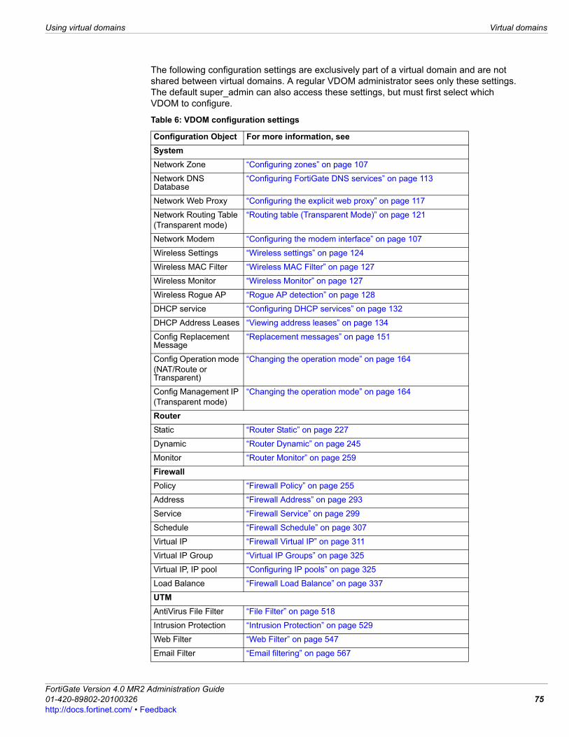
Using virtual domains Virtual domains
The following configuration settings are exclusively part of a virtual domain and are not shared between virtual domains. A regular VDOM administrator sees only these settings. The default super_admin can also access these settings, but must first select which VDOM to configure.
Table 6: VDOM configuration settings
Configuration Object For more information, seeSystemNetwork Zone “Configuring zones” on page 107
Network DNS Database
“Configuring FortiGate DNS services” on page 113
Network Web Proxy “Configuring the explicit web proxy” on page 117
Network Routing Table(Transparent mode)
“Routing table (Transparent Mode)” on page 121
Network Modem “Configuring the modem interface” on page 107
Wireless Settings “Wireless settings” on page 124
Wireless MAC Filter “Wireless MAC Filter” on page 127
Wireless Monitor “Wireless Monitor” on page 127
Wireless Rogue AP “Rogue AP detection” on page 128
DHCP service “Configuring DHCP services” on page 132
DHCP Address Leases “Viewing address leases” on page 134
Config Replacement Message
“Replacement messages” on page 151
Config Operation mode (NAT/Route or Transparent)
“Changing the operation mode” on page 164
Config Management IP (Transparent mode)
“Changing the operation mode” on page 164
RouterStatic “Router Static” on page 227
Dynamic “Router Dynamic” on page 245
Monitor “Router Monitor” on page 259
FirewallPolicy “Firewall Policy” on page 255
Address “Firewall Address” on page 293
Service “Firewall Service” on page 299
Schedule “Firewall Schedule” on page 307
Virtual IP “Firewall Virtual IP” on page 311
Virtual IP Group “Virtual IP Groups” on page 325
Virtual IP, IP pool “Configuring IP pools” on page 325
Load Balance “Firewall Load Balance” on page 337
UTMAntiVirus File Filter “File Filter” on page 518
Intrusion Protection “Intrusion Protection” on page 529
Web Filter “Web Filter” on page 547
Email Filter “Email filtering” on page 567
FortiGate Version 4.0 MR2 Administration Guide01-420-89802-20100326 75http://docs.fortinet.com/ • Feedback
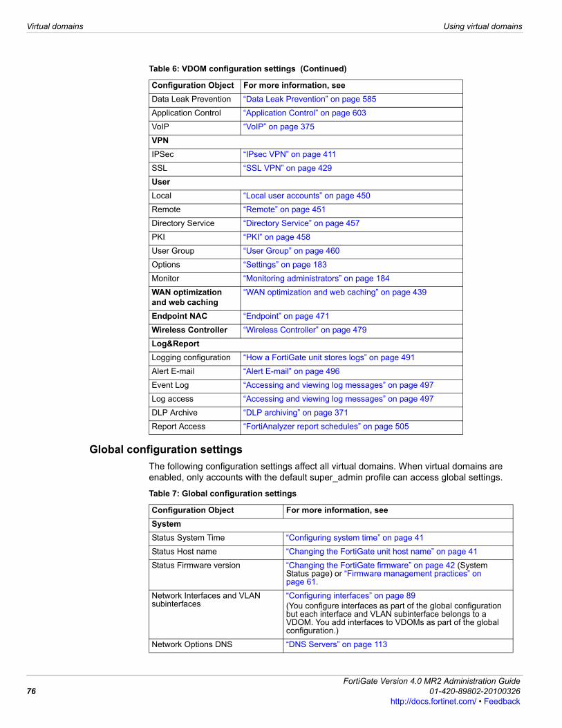
Virtual domains Using virtual domains
76
Global configuration settingsThe following configuration settings affect all virtual domains. When virtual domains are enabled, only accounts with the default super_admin profile can access global settings.
Data Leak Prevention “Data Leak Prevention” on page 585
Application Control “Application Control” on page 603
VoIP “VoIP” on page 375
VPNIPSec “IPsec VPN” on page 411
SSL “SSL VPN” on page 429
UserLocal “Local user accounts” on page 450
Remote “Remote” on page 451
Directory Service “Directory Service” on page 457
PKI “PKI” on page 458
User Group “User Group” on page 460
Options “Settings” on page 183
Monitor “Monitoring administrators” on page 184
WAN optimization and web caching
“WAN optimization and web caching” on page 439
Endpoint NAC “Endpoint” on page 471
Wireless Controller “Wireless Controller” on page 479
Log&ReportLogging configuration “How a FortiGate unit stores logs” on page 491
Alert E-mail “Alert E-mail” on page 496
Event Log “Accessing and viewing log messages” on page 497
Log access “Accessing and viewing log messages” on page 497
DLP Archive “DLP archiving” on page 371
Report Access “FortiAnalyzer report schedules” on page 505
Table 6: VDOM configuration settings (Continued)
Configuration Object For more information, see
Table 7: Global configuration settings
Configuration Object For more information, seeSystemStatus System Time “Configuring system time” on page 41
Status Host name “Changing the FortiGate unit host name” on page 41
Status Firmware version “Changing the FortiGate firmware” on page 42 (System Status page) or “Firmware management practices” on page 61.
Network Interfaces and VLAN subinterfaces
“Configuring interfaces” on page 89(You configure interfaces as part of the global configuration but each interface and VLAN subinterface belongs to a VDOM. You add interfaces to VDOMs as part of the global configuration.)
Network Options DNS “DNS Servers” on page 113
FortiGate Version 4.0 MR2 Administration Guide01-420-89802-20100326
http://docs.fortinet.com/ • Feedback
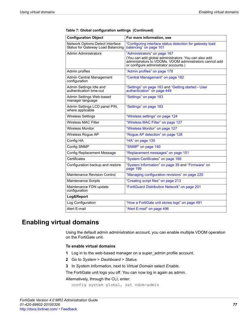
Using virtual domains Enabling virtual domains
Enabling virtual domainsUsing the default admin administration account, you can enable multiple VDOM operation on the FortiGate unit.
To enable virtual domains1 Log in to the web-based manager on a super_admin profile account.2 Go to System > Dashboard > Status.3 In System Information, next to Virtual Domain select Enable.The FortiGate unit logs you off. You can now log in again as admin. Alternatively, through the CLI, enter:
config system global, set vdom-admin
Network Options Detect Interface Status for Gateway Load Balancing
“Configuring interface status detection for gateway load balancing” on page 101
Admin Administrators “Administrators” on page 167(You can add global administrators. You can also add administrators to VDOMs. VDOM administrators cannot add or configure administrator accounts.)
Admin profiles “Admin profiles” on page 178
Admin Central Management configuration
“Central Management” on page 182
Admin Settings Idle and authentication time-out
“Settings” on page 183 and “Getting started - User authentication” on page 449
Admin Settings Web-based manager language
“Settings” on page 183
Admin Settings LCD panel PIN, where applicable
“Settings” on page 183
Wireless Settings “Wireless settings” on page 124
Wireless MAC Filter “Wireless MAC Filter” on page 127
Wireless Monitor “Wireless Monitor” on page 127
WIreless Rogue AP “Rogue AP detection” on page 128
Config HA “HA” on page 135
Config SNMP “SNMP” on page 140
Config Replacement Message “Replacement messages” on page 151
Certificates “System Certificates” on page 189
Configuration backup and restore “System Information” on page 39 and “Firmware” on page 199
Maintenance Revision Control “Managing configuration revisions” on page 220
Maintenance Scripts “Creating script files” on page 213
Maintenance FDN update configuration
“FortiGuard Distribution Network” on page 201
Log&ReportLog Configuration “How a FortiGate unit stores logs” on page 491
Alert E-mail “Alert E-mail” on page 496
Table 7: Global configuration settings (Continued)
Configuration Object For more information, see
FortiGate Version 4.0 MR2 Administration Guide01-420-89802-20100326 77http://docs.fortinet.com/ • Feedback
Configuring VDOMs and global settings Using virtual domains
78
When virtual domains are enabled, the web-based manager and the CLI are changed as follows:• Global and per-VDOM configurations are separated. For more information, see “VDOM
configuration settings” on page 74, and “Global configuration settings” on page 76.• A new menu appears called Current VDOM, which you can use to go from VDOM to
VDOM. For more information, see “Switching between VDOMs” on page 85.• A new VDOM entry appears under the System option.• Within a VDOM, reduced dashboard menu options are available, and a new Global
option appears. Selecting Global exits the current VDOM.• There is no operation mode option at the Global level.• Only super_admin profile accounts can view or configure Global level options. • Super_admin profile accounts can configure configurations for all VDOM.• One or more administrators can be configured for each VDOM; however, these admin
accounts cannot edit settings for any VDOMs for which they are not configured.When virtual domains are enabled, the current virtual domain is displayed at the bottom left of the screen, in the format Current VDOM: <name of the virtual domain>.
Configuring VDOMs and global settingsA VDOM is not useful unless it contains at least two physical interfaces or virtual subinterfaces for incoming and outgoing traffic. Availability of the associated tasks depends on the permissions of the admin. If your are using a super_admin profile account, you can perform all tasks. If you are using a regular admin account, the tasks available to you depend on whether you have read only or read/write permissions, Table 6 shows what roles can perform which tasks.
This section includes:• VDOM licenses• Creating a new VDOM• Disabling a VDOM• Working with VDOMs and global settings• Adding interfaces to a VDOM
Table 8: Admin VDOM permissions
Tasks Regular administrator account Super_admin profile administrator account
Read only permission
Read/write permission
View global settings yes yes yes
Configure global settings no no yes
Create or delete VDOMs no no yes
Configure multiple VDOMs no no yes
Assign interfaces to a VDOM no no yes
Create VLANs no yes - for 1 VDOM yes - for all VDOMs
Assign an administrator to a VDOM no no yes
Create additional admin accounts no yes - for 1 VDOM yes - for all VDOMs
Create and edit protection profiles no yes - for 1 VDOM yes - for all VDOMs
FortiGate Version 4.0 MR2 Administration Guide01-420-89802-20100326
http://docs.fortinet.com/ • Feedback
Using virtual domains Configuring VDOMs and global settings
• Inter-VDOM links• Assigning an interface to a VDOM• Assigning an administrator to a VDOM• Changing the management VDOM• Switching between VDOMs
VDOM licensesAll FortiGate units, except the FortiGate-30B, support 10 VDOMs by default. If you do not have a System > Maintenance > License tab, your FortiGate model does not support more than 10 VDOMs.High-end FortiGate models support the purchase of a VDOM license key from customer service to increase their maximum allowed VDOMs to 25, 50, 100, 250, or 500. Configuring 250 or more VDOMs will result in reduced system performance.
To obtain a VDOM license key1 Log in to your FortiGate unit using the admin account.
Other accounts such as other super_admin profile accounts may also have sufficient privileges to install VDOM licenses.
2 Go to System > Dashboard > Status.3 Record your FortiGate unit serial number as shown in “System Information” on
page 39.4 In the License Information widget, in the Virtual Domains line, select Purchase More.
You will then be taken to the Fortinet customer support web site where you can log in and purchase a license key for 25, 50, 100, 250, or 500 VDOMs.
5 When you receive your license key, go to System > Maintenance > License.6 In the License Key field, enter the 32-character license key you received from Fortinet
customer support.7 Select Apply.To verify the new VDOM license, go to System > Dashboard > Status under Global Configuration. In the License Information area Virtual Domains, VDOMs Allowed shows the maximum number of VDOMs allowed.
Table 9: VDOM support by FortiGate model
FortiGate model Support VDOMs
Default VDOM maximum
Maximum VDOM license
30B no 0 0
Low and mid-range models yes 10 10
High-end models yes 10 500
Note: Your FortiGate unit has limited resources that are divided amongst all configured VDOMs. These resources include system memory and CPU. When running 250 or more VDOMs, you cannot run Unified Threat Management (UTM) features such as proxies, web filtering, or antivirus—your FortiGate unit can only provide basic firewall functionality.
FortiGate Version 4.0 MR2 Administration Guide01-420-89802-20100326 79http://docs.fortinet.com/ • Feedback
Configuring VDOMs and global settings Using virtual domains
80
Creating a new VDOMBy default, every FortiGate unit has a root VDOM that is visible when VDOMs are enabled. To use additional VDOMs, you must first create them.When using multiple VDOMs, it can be useful to assign fewer resources to some VDOMs and more resources to others. This VDOM resource management will result in better FortiGate unit performance. For more information, see “Configuring resource usage for individual VDOMs” on page 86.VDOM names have the following restrictions:• Only letters, numbers, “-”, and “_” are allowed.• A name can have no more than 11 characters.• A name cannot contain spaces.• VDOMs cannot have the same names as interfaces, zones, switch interfaces, or other
VDOMsThe VDOM names vsys_ha and vsys_fgfm are in use by the FortiGate unit. If you attempt to name a new VDOM vsys_ha or vsys_fgfm, the FortiGate unit will generate an error.
To create a new VDOM1 Log in as a super_admin profile admin.2 Ensure VDOMs are enabled. For more information, see “Enabling virtual domains” on
page 77.3 Go to System > VDOM > VDOM.4 Select Create New.5 On the New Virtual Domain page, enter a name for the new VDOM, up to a maximum
of 11 characters. This name cannot be changed.6 Optionally enter a comment for the VDOM, up to a maximum of 63 characters.7 Select OK.
Disabling a VDOMWhen you have multiple VDOMs configured, it can be useful to disable one VDOM temporarily instead of deleting and re-creating it later. Disabling can be used during initial configuration, equipment changes, or even a DoS attack.A disabled VDOM has en empty Enable checkbox. A VDOM with a greyed-out checkbox is the management VDOM can cannot be disabled.
Note: VDOMs created on a registered FortiGate unit are recognized as real devices by connected FortiAnalyzer units. FortiAnalyzer units include VDOMs in their total number of registered devices. For example, if three FortiGate FortiGate units are registered on a FortiAnalyzer unit and they contain a total of four VDOMs, the total number of registered FortiGate units on the FortiAnalyzer unit is seven units. For more information, see the FortiAnalyzer Administration Guide.
Note: When creating 250 or more VDOMs, you cannot enable UTM features such as proxies, web filtering, and antivirus due to limited resources. Also when creating large numbers of VDOMs, you may experience reduced performance. To improve performance with multiple VDOMs, see “Configuring resource usage for individual VDOMs” on page 86.
FortiGate Version 4.0 MR2 Administration Guide01-420-89802-20100326
http://docs.fortinet.com/ • Feedback
Using virtual domains Configuring VDOMs and global settings
Re-enabling is simply a matter of checking the Enable box and answering the prompt.
To disable a VDOM1 Log in as a super_admin profile admin.2 Go to System > VDOM > VDOM.3 For the VDOM to be disabled, unselect the Enable checkbox.4 Confirm your choice when prompted.
Working with VDOMs and global settingsWhen you log in as admin and virtual domains are enabled, the FortiGate unit is automatically in global configuration, as demonstrated by the appearance of the VDOM option under System.To work with virtual domains, select System > VDOM > VDOM.
VDOM pageLists all VDOMs that you have created, as well as the default root VDOM. On this page, you can edit, delete or create a new VDOM. This page also allows you to switch to a VDOM.
Create New Select to add a new VDOM. Enter the new VDOM name and select OK.The VDOM must not have the same name as an existing VDOM, VLAN or zone. The VDOM name can have a maximum of 11 characters and must not contain spaces.
Edit Select to change the description of the VDOM. The name of the VDOM cannot be changed. When you are editing an existing VDOM, you are automatically redirected to the Edit Virtual Domain page.
Delete Select to remove the VDOM.
Switch Management [<management_vdom>]
Change the management VDOM to the selected VDOM in the list. The management VDOM then appears beside the name Switch Management in square brackets, for example, Switch Management [vdom_1]. The default management VDOM is root. For more information, see “Changing the management VDOM” on page 84.
Name The name of the VDOM.
Operation Mode The VDOM operation mode, either NAT or Transparent.When a VDOM is in Transparent mode, SNMP can display the management address, address type and subnetmask for that VDOM. For more information, see “SNMP” on page 140.
Interfaces The interfaces associated with this VDOM, including virtual interfaces.Every VDOM includes an SSL VPN virtual interface named for that VDOM. For the root VDOM this interface is ssl.root.
Enable There are three states this column can be in.• A green check mark indicates this VDOM is enabled, and that you can
select the Enter icon to change to that VDOM. • An empty check box indicates this VDOM is disabled. When disabled,
the configuration of that VDOM is preserved. The Enter icon is not available.
• A grayed-out check box indicates this VDOM is the management VDOM. It cannot be deleted or changed to disabled; it is always active.
Comments Comments added by an admin when this VDOM was created.
New Virtual Domain pageProvides settings for configuring a new VDOM. When edit an existing VDOM, you are automatically redirected to the Edit Virtual Domain page where you can modify the maximum and guaranteed amount of system resources.
Name Enter a name for the VDOM.
FortiGate Version 4.0 MR2 Administration Guide01-420-89802-20100326 81http://docs.fortinet.com/ • Feedback
Configuring VDOMs and global settings Using virtual domains
82
•
Adding interfaces to a VDOMA VDOM must contain at least two interfaces to be useful. These can be physical or virtual interfaces such as VLAN subinterfaces. By default, all physical interfaces are in the root virtual domain. For more information on types of interfaces, see “Configuring interfaces” on page 89.VLAN subinterfaces often need to be in a different VDOM than their physical interface. To do this, the super administrator must first create the VDOM, create the VLAN subinterface, and then assign the VLAN to the correct VDOM. VDOMs can only be added in global settings, and not within VDOMs. For information on creating VLAN subinterfaces, see “Adding VLAN interfaces” on page 95.
Inter-VDOM linksAn inter-VDOM link is a pair of interfaces that enable you to communicate between two VDOMs internally without using a physical interface. Inter-VDOM links have the same security as physical interfaces, but allow more flexible configurations that are not limited by the number of physical interfaces on your FortiGate unit. As with all virtual interfaces, the speed of the link depends on the CPU load, but generally it is faster than physical interfaces. There are no MTU settings for inter-VDOM links. DHCP support includes inter-VDOM links.A packet can pass through an inter-VDOM link a maximum of three times. This is to prevent a loop. When traffic is encrypted or decrypted, it changes the content of the packets and this resets the inter-VDOM counter. However, using IPIP or GRE tunnels does not reset the counter.In HA mode, inter-VDOM links must have both ends of the link within the same virtual cluster. DHCP over IPSec is supported for inter-VDOM links, however regular DHCP services are not available. To view inter-VDOM links, go to System > Network > Interface. When an inter-VDOM link is created, it automatically creates a pair of virtual interfaces that correspond to the two internal VDOMs. Each of the virtual interfaces is named using the inter-VDOM link name with an added “0” or “1”. So if the inter-VDOM link is called “vlink” the interfaces are “vlink0” and “vlink1”. Select the Expand Arrow beside the VDOM link to display the virtual interfaces.
Enable Select to enable the VDOM.
Comments Enter a description about the VDOM. This is optional.
Edit Virtual Domain pageProvides settings for changing the maximum amount of system resources.
Name The name of the VDOM. You cannot change the VDOM name when editing a VDOM. 1
Enable Indicates that the VDOM is either enabled or disabled. You cannot change whether the VDOM is enabled or disable when editing a VDOM.
Comments Change the description in this field, if you want. This is optional.
Resource Usage Enter a number for the maximum and guaranteed fields. For more information about changing system resource limits, see “Configuring resource usage for individual VDOMs” on page 86.
Note: Inter-VDOM links cannot refer to a domain that is in transparent mode.
FortiGate Version 4.0 MR2 Administration Guide01-420-89802-20100326
http://docs.fortinet.com/ • Feedback
Using virtual domains Configuring VDOMs and global settings
To create an inter-VDOM link1 Log in as admin.2 Go to System > Network > Interface.3 Select the arrow on the Create New button.4 Select VDOM link.
You will see the New VDOM Link screen. 5 Enter the name for the new VDOM link, up to a maximum of 11 characters.
The name must not contain any spaces or special characters. Hyphens (“-”) and underlines (“_”) are allowed. Remember that the name will have a “0” or “1” attached to the end for the actual interfaces.
6 Configure VDOM link “0”.7 Select the VDOM from the menu that this interface will connect to.8 Enter the IP address and netmask for this interface. 9 Select the administrative access method or methods. Keep in mind that PING,
TELNET, and HTTP are less secure methods.10 Optionally enter a description for this interface. 11 Repeat steps 7 through 10 for VDOM link “1”.12 Select OK to save your configuration and return to the System > Interface screen.
Assigning an interface to a VDOMYou cannot delete a VDOM if it is used in any configurations. For example, if an interface is assigned to that VDOM, you cannot delete the VDOM. You cannot remove an interface from a VDOM if the interface is included in any of the following configurations: • DHCP server• zone• routing • load balancing• firewall policy including DoS policies and one-armed sniffer policies• proxy arp (only accessible through the CLI).Before removing these configurations, it is recommended that you back up your configuration, so you can restore it if you want to create this VDOM at a later date. Delete the items in this list or modify them to remove the interface before proceeding. The VDOM field on the Edit screen for that interface will change from being greyed out and locked when there are no more objects tied to that interface.
The following procedure describes how to reassign an existing interface from one virtual domain to another. It assumes VDOMs are enabled and more than one VDOM exists.
Note: You can reassign or remove an interface or subinterface once the Delete icon is displayed. If the icon is absent, it means that the interface is being used in a configuration somewhere.
Tip: You can disable a VDOM instead of deleting it. Your configuration will be preserved, saving time you would otherwise need to remove and reconfigure it. For more information, see “Working with VDOMs and global settings” on page 81.
FortiGate Version 4.0 MR2 Administration Guide01-420-89802-20100326 83http://docs.fortinet.com/ • Feedback
Configuring VDOMs and global settings Using virtual domains
84
To assign an interface to a VDOM1 Log in as admin.2 Go to System > Network > Interface.3 Select Edit for the interface that you want to reassign.4 Select the new virtual domain for the interface.5 Configure other settings as required and select OK.
For more information, see “Configuring interface settings” on page 92.The interface is assigned to the VDOM. Existing firewall virtual IP addresses for this interface are deleted. You should manually delete any routes that refer to this interface, and create new routes for this interface in the new VDOM. Otherwise your network traffic will not be properly routed. For more information on creating static routes, see “Router Static” on page 227.
Assigning an administrator to a VDOMIf you are creating a VDOM to serve an organization that will be administering its own resources, you need to create an administrator account for that VDOM.A VDOM admin can change configuration settings within that VDOM but cannot make changes that affect other VDOMs on the FortiGate unit.A regular administrator assigned to a VDOM can log in to the web-based manager or the CLI only on interfaces that belong to that VDOM. The super administrator can connect to the web-based manager or CLI through any interface on the FortiGate unit that permits management access. Only the super administrator or a regular administrator of the root domain can log in by connecting to the console interface.
To assign an administrator to a VDOM1 Log in as the super_admin. 2 Ensure that virtual domains are enabled. For more information, see “Enabling virtual
domains” on page 77.3 Go to System > Admin > Administrators.4 Create a new administrator account or select the Edit icon of an existing administrator
account.5 Go to the Virtual Domain list.6 Select the VDOM that this administrator manages.
Administrators are assigned to a specific VDOM when the account is created unless they are super_admin administrators. For more information, see “Configuring an administrator account” on page 169.
7 Configure other settings as required.For detailed information, see “Configuring an administrator account” on page 169.
8 Select OK.
Changing the management VDOMThe management VDOM on your FortiGate unit is where some default types of traffic originate, including:
Note: If an admin account is assigned to a VDOM, that VDOM cannot be deleted until that account is assigned to another VDOM or removed.
FortiGate Version 4.0 MR2 Administration Guide01-420-89802-20100326
http://docs.fortinet.com/ • Feedback
Using virtual domains Configuring VDOM resource limits
• SNMP• logging• alert email• FDN-based updates• NTP-based time setting.Before you change the management VDOM, ensure that virtual domains are enabled on the system dashboard screen. For more information, see “Enabling virtual domains” on page 77.Only one VDOM can be the management VDOM at any given time.Global events are logged with the VDOM set to the management VDOM.
To change the management VDOM1 Go to System > VDOM > VDOM.2 From the list of VDOMs, select the VDOM to be the new management VDOM.
This list is located to the immediate left of the Apply button.3 Select Apply to make the change.
At the prompt, confirm the change.Management traffic will now originate from the new management VDOM.
Switching between VDOMsYou can easily switch between VDOMs using the Current VDOM menu that appears after you have enabled VDOMs on your FortiGate unit. The Current VDOM menu contains a drop-down list which is located beside the menu’s name. The drop-down list contains all VDOMs that you created, including the default root VDOM and Global. To switch to another VDOM, in the Current VDOM menu, select the VDOM that you want to switch to from the drop-down list. You are automatically redirected to that VDOM within the web-based manager.
Configuring VDOM resource limitsSuper administrators can configure VDOM resource limits to control how many resources each VDOM can use. This means you can provide tiered services for different VDOMs. You can also use resource limits to share resources evenly among VDOMs, preventing one VDOM from affecting the performance of others. You can set limits for dynamic and some static resources. Dynamic resources are resources that are not controlled by the FortiGate configuration. You can limit dynamic resources to limit the amount of traffic that a VDOM processes and so limit the amount of FortiGate processing resources the VDOM can use. If you do not limit the number of dynamic resources each VDOM will use as many as it can until the capacity of the FortiGate unit becomes the limiting factor. You can set the following dynamic resource limits:• The total number of communication Sessions that can be started in a VDOM. When
this limit is reached additional sessions are dropped.
Note: You cannot change the management VDOM if any administrators are using RADIUS authentication.
FortiGate Version 4.0 MR2 Administration Guide01-420-89802-20100326 85http://docs.fortinet.com/ • Feedback
Configuring VDOM resource limits Using virtual domains
86
• The number of IPSec VPN Dal-up Tunnels that can be started in a VDOM. When this limit is reached, additional tunnels are dropped.
• The number of SSL VPN user sessions that can be started in a VDOM. When this limit is reached the VDOM displays a system busy message instead of the login page when a user attempts to login to start an SSL VPN session.
Static resources are controlled by limits in the FortiGate configuration. These limits vary by model and are listed in the FortiGate Maximum Values Matrix. Limiting static resources does not limit the amount of traffic that the VDOM process. Instead limiting static resources controls the number of configuration elements that can be added to a VDOM. You can set the following static resource limits:• The number of VPN IPSec Phase 1 and Phase 2 tunnels that can be added to a VDOM
configuration. The number of tunnels is limited by the maximum values for the FortiGate model.
• The number of Firewall policies, Protection Profiles, Firewall Addresses, Firewall Address Groups, Firewall Custom Services, Firewall Service Groups, Firewall One-Time Schedules, and Firewall Recurring Schedules that can be added to a VDOM configuration.
• The number of Local Users and User Groups that can be added to a VDOM configuration.
Setting VDOM global resource limitsUse global resource limits to configure resource limits that will apply to all VDOMs. When you set a global resource limit, you cannot exceed that resource limit in any VDOM. For example, if you want to limit all VDOMS to 100 VPN IPSec Phase 1 Tunnels, go to System > VDOM > Global Resources and edit the VPN IPsec Phase1 Tunnels resource limit and set the global resource limit to 100. With this global limit set you can add a maximum of 100 VPN IPSec Phase 1 Tunnels to any VDOM. You can also edit the resource limits for individual VDOMs to further limit the number of resources that you can add to individual VDOMs. See “Configuring resource usage for individual VDOMs” on page 86.A resource limit of 0 means no limit. No limit means the resource is not being limited by the resource limit configuration. Instead the resource is being limited by other factors. The FortiGate unit limits dynamic resources by the capacity of the FortiGate unit and can vary depending on how busy the system is. Limits for static resources are set by limitations in the FortiGate configuration as documented in the FortiGate Maximum Values Matrix document.
Configuring resource usage for individual VDOMsYou can configure resource usage for individual VDOMS to override global limits and specify guaranteed usage for that VDOM.When you add a new VDOM, after giving the VDOM a name and selecting OK you can configure resource usage for the VDOM. You can also configure resource usage for a VDOM at any time by going to System > VDOM and selecting the edit icon for a VDOM.When configuring resource usage for a VDOM you can set the Maximum and Guaranteed value for each resource.
FortiGate Version 4.0 MR2 Administration Guide01-420-89802-20100326
http://docs.fortinet.com/ • Feedback
Using virtual domains Configuring VDOM resource limits
• The Maximum value limits the amount of the resource that can be used by the VDOM. When you add a VDOM, all maximum resource usage settings are 0, indicating that resource limits for this VDOM are controlled by the global resource limits. You do not have to override the maximum settings unless you need to override global limits to further limit the resources available for the VDOM. You cannot set maximum resource usage higher in a VDOM than the corresponding global resource limit. To set global resource limits go to System > VDOM > Global Resources. See “Setting VDOM global resource limits” on page 86.
• The Guaranteed value represents the minimum amount of the resource available for that VDOM. Setting the guaranteed value makes sure that other VDOMs do not use all of a resource. A guaranteed value of 0 means that an amount of this resource is not guaranteed for this VDOM. You only have to change guaranteed settings if your FortiGate may become low on resources and you want to guarantee that a minimum level is available for this VDOM.
Resource Usage section on the Edit Virtual Domain pageResource Name of the resource. Includes dynamic and static resources.
Maximum Override the global limit to reduce the amount of each resource available for this VDOM. The maximum must the same as or lower than the global limit. The default value is 0, which means the maximum is the same as the global limit. Note: If you set the maximum resource usage for a VDOM you cannot reduce the default maximum global limit for all VDOMs below this maximum.
Guaranteed Enter the minimum amount of the resource available to this VDOM regardless of usage by other VDOMs. The default value is 0, which means that an amount of this resource is not guaranteed for this VDOM.
Current The amount of the resource that this VDOM currently uses.
FortiGate Version 4.0 MR2 Administration Guide01-420-89802-20100326 87http://docs.fortinet.com/ • Feedback

Configuring VDOM resource limits Using virtual domains
88
FortiGate Version 4.0 MR2 Administration Guide01-420-89802-20100326http://docs.fortinet.com/ • Feedback
System Network Configuring interfaces
System NetworkThis section describes how to configure your FortiGate unit to operate in your network. Basic network settings include configuring FortiGate interfaces and DNS options. More advanced configuration includes adding zones and VLAN subinterfaces to the FortiGate network configuration. Optional configurations also include configuring the FortiGate unit as a DNS server and an explicit web proxy serverIf you enable virtual domains (VDOMs) on the FortiGate unit, you configure interface and networking options globally for the entire FortiGate unit. All interface settings, including adding interfaces to VDOMs, are part of the global configuration. You configure zones, the modem interface, the DNS database, the explicit web proxy, and the Transparent mode routing table separately for each VDOM. For more information, see “Using virtual domains” on page 73.The following topics are included in this section:• Configuring interfaces• Configuring zones• Configuring the modem interface• Configuring FortiGate DNS services• Configuring the explicit web proxy• Configuring WCCP• Routing table (Transparent Mode)
Configuring interfacesGo to System > Network > Interface to configure FortiGate interfaces. Many interface options are available. Different options are available in NAT/Route mode and in Transparent mode.Some of the options available include: • modify the configuration of a physical interface• add VLAN subinterfaces• aggregate several physical interfaces into an IEEE 802.3ad aggregate interface (some
models)• combine several physical interfaces into a redundant interface (some models)• add loopback interfaces• add wireless interfaces (FortiWiFi models) and service set identifiers (SSIDs)• add VDOM links on FortiGate units with multiple VDOMs enabled • add an sFlow sampler to support sFlow (CLI only)
Note: Unless stated otherwise, the term interface can refer to either a physical FortiGate interface or to a virtual FortiGate VLAN subinterface.
If you can enter both an IP address and a netmask in the same field, you can use the short form of the netmask. For example, 192.168.1.100/255.255.255.0 can also be entered as 192.168.1.100/24.
FortiGate Version 4.0 MR2 Administration Guide01-420-89802-20100326 89http://docs.fortinet.com/ • Feedback
Configuring interfaces System Network
90
• configure the modem interface (on some models) • detect interface status for gateway load balancing• change the information displayed about the interfaces• configure a virtual wireless access point (VAP) interface
Interface pageLists all the interfaces that are default and those that you have created. On this page you can view the status of each interface, create a new interface, edit an existing interface, or remove an interface.
Create New Select Create New to add a new interface. When you select Create New, you are automatically redirected to the New Interface page. Depending on the model you can add a VLAN interface, a loopback interface, a IEEE 802.3ad aggregated interface, or a redundant interface.• “Adding VLAN interfaces” on page 95• “Adding loopback interfaces” on page 95• “Adding 802.3ad aggregate interfaces” on page 96• “Adding redundant interfaces” on page 97When VDOMs are enabled, you can also select Create New to add Inter-VDOM links. For more information see “Inter-VDOM links” on page 82.
Switch Mode On supported models, select Switch Mode to change between switch mode and interface mode. Switch mode combines some FortiGate interfaces into one switch with one IP address. Interface mode allows you to configure them as separate interfaces.On some FortiGate models you can also select Hub Mode. Hub mode is similar to switch mode except that in hub mode the interfaces do not learn the MAC addresses of the devices on the network they are connected to and may also respond quicker to network changes. Normally, you would only select Hub Mode if you are having network performance issues when operating with switch mode. The configuration of the FortiGate unit is the same whether in switch mode or hub mode.Before switching modes, all configuration settings for the interfaces affected by the change must be set to defaults. When you select Switch Mode the web-based manager displays the list of affected interfaces.See “Switch Mode” on page 92.
Show backplane interfaces
Select to make FortiGate -5000 series backplane interfaces visible. Once visible, these interfaces can be configured as regular physical interfaces.
Column Settings Select to change the columns of information that are displayed on the interface list. Fore more information, see “Using column settings to control the columns displayed” on page 35.
Description Display a description for the interface is one has been added. For more information, see “Configuring interface settings” on page 92.
Name The names of the physical interfaces on your FortiGate unit. This includes any alias names that have been configured.
The names of the physical interfaces depend on the model. Some names indicate the default function of the interface such as internal, external, wan1 (wide are network), wlan (wireless LAN) and dmz. Other names are more generic such as port1, port20, and so on.Some FortiGate models also include a modem interface named modem. See “Configuring the modem interface” on page 107.
When you combine several interfaces into an aggregate or redundant interface, only the aggregate or redundant interface is listed, not the component interfaces. See “Adding 802.3ad aggregate interfaces” on page 96 or “Adding redundant interfaces” on page 97.
On FortiGate models that support switch mode, the individual interfaces in the switch are not displayed when in switch mode. For more information, see “Switch Mode” on page 92.If you have added VLAN interfaces, they also appear in the name list, below the physical or aggregated interface to which they have been added. See the FortiGate VLANs and VDOMs Guide.
FortiGate Version 4.0 MR2 Administration Guide01-420-89802-20100326
http://docs.fortinet.com/ • Feedback
System Network Configuring interfaces
f you have added loopback interfaces, they also appear in the interface list, below the physical interface to which they have been added.If you have software switch interfaces configured, you will be able to view them. For more information, see “Adding software switch interfaces” on page 105.
If you have interface mode enabled on a FortiGate model with a switch interface, you will see multiple internal interfaces. If switch mode is enabled, there will only be one internal interface. For more information see “Switch Mode” on page 92.
If your FortiGate unit supports AMC modules and have installed an AMC module containing interfaces (for example, the ASM-FB4 contains 4 interfaces) these interfaces are added to the interface status display. The interfaces are named amc-sw1/1, amc-dw1/2, and so on. sw1 indicates it is a single width or double width card respectively in slot 1. The last number “/1” indicates the interface number on that card - for the ASM-FB4 card there would be “/1” through “/4”.
IP/Netmask The current IP address/netmask of the interface.In VDOM mode, when VDOMs are not all in NAT or Transparent mode some values may not be available for display and will be displayed as “-” instead.When IPv6 Support is enabled on the web-based manager, IPv6 addresses may be displayed in this column.
Access The administrative access configuration for the interface.For more information, see “Configuring administrative access to an interface” on page 101.
Administrative Status
The administrative status for the interface.If the administrative status is a green arrow, the interface is up and can accept network traffic. If the administrative status is a red arrow, the interface is administratively down and cannot accept traffic. To change the administrative status of an interface, select the Edit icon to edit the interface and change the Administrative Status setting for the interface.
Link Status The status of the interface physical connection. Link status can be either up or down. If link status is up there is an active physical connection between the physical interface and a network switch. If link status is down the interface is not connected to the network or there is a problem with the connection. You cannot change link status from the web-based manager.Link status is only displayed for physical interfaces.
MAC The MAC address of the interface.
Mode Shows the addressing mode of the interface. The addressing mode can be manual, DHCP, or PPPoE.
MTU The maximum number of bytes per transmission unit (MTU) for the interface. See “Changing interface MTU packet size” on page 102.
Secondary IP Displays the secondary IP addresses added to the interface. See “Adding secondary IP addresses to an interface” on page 103.
Type The type of the interface. Valid types include:• Physical - a physical network interface, including the modem interface• VLAN - a VLAN interface• Aggregate - a group of 802.3ad aggregated interfaces• Redundant - a group of redundant interfaces• VDOM Link - a pair of virtual interfaces that link two VDOMs• Pair - one two interfaces that are joined together, such as 2 VDOM links• Switch - two or more interfaces joined together to create a software switch
interface• Tunnel - a virtual IPSec VPN interface• VAP - a wireless controller virtual access point (VAP or virtual AP) interface
Virtual Domain The virtual domain to which the interface belongs. This column is visible when VDOM configuration is enabled.
VLAN ID The configured VLAN ID for VLAN subinterfaces.
FortiGate Version 4.0 MR2 Administration Guide01-420-89802-20100326 91http://docs.fortinet.com/ • Feedback
Configuring interfaces System Network
92
See also• Switch Mode
Switch ModeSwitch mode allows you to switch a group of related FortiGate interfaces to operate as a multi-port switch with one IP address. Switch mode is available on FortiGate models with switch hardware.The switch mode feature has two states - switch mode and interface mode. Switch mode is the default mode with only one interface and one address for the entire internal switch. Interface mode allows you to configure each of the internal switch physical interface connections separately. This allows you to assign different subnets and netmasks to each of the internal physical interface connections.Before you are able to change between switch mode and interface mode, all configuration settings for the affected interfaces must be set to defaults. This includes firewall policies, routing, DNS forwarding, DHCP services, VDOM interface assignments, and routing. If they are not removed, you will not be able to switch modes, and you will see an error message. The web-based manager displays the list of affected interfaces.Selecting Switch Mode on the System > Network > Interface screen displays the Switch Mode Management screen. From the FortiGate CLI you can also add software switch interfaces. For more information, see “Adding software switch interfaces” on page 105.
See also• Configuring interface settings
Configuring interface settingsGo to System > Network > Interface and select Create New to add and configure a VLAN, loopback, IEEE 802.3ad aggregated, or a redundant interface. You can also edit an existing interface to change the settings for an interface.
Delete Delete the interface. Available for interfaces added by selecting Create New. For example, you can delete VLAN, loopback, aggregate, and redundant interfaces. You can only deleted an interface if it is not used in another configuration.
Edit Change the interface’s configuration.
View View the interface’s configuration.
Interface page (FortiWiFi models only)Provides settings for switching a group of related FortiGate interfaces to operate as a multi-port switch with one IP address.
Switch Mode Select Switch Mode. Only one internal interface is displayed. This is the default mode.
Interface Mode Select Interface Mode. All internal i nterfaces on the switch are displayed as individually configurable interfaces.
Hub Mode On some FortiGate models you can select Hub Mode. Hub mode is similar to switch mode except t hat in hub mode the interfaces do not learn the MAC addresses of the devices on the network they are connected to and may also respond quicker to network changes in some circumstances. You should only select Hub Mode if you are having network performance issues when operating with switch mode. The configuration of the FortiGate unit is the same whether in switch mode or hub mode.
FortiGate Version 4.0 MR2 Administration Guide01-420-89802-20100326
http://docs.fortinet.com/ • Feedback
System Network Configuring interfaces
New Interface pageProvides settings for configuring a new interface. When you select Create New on the Interface page, you are automatically redirected to this page. If you are editing an existing interface, you are automatically redirected to the Edit Interface page.
Name The name of the interface. You can specify and change the names of VLAN, loopback, IEEE 802.3ad aggregated, and redundant interfaces.You cannot change the name of an existing interface.The interface display also includes the MAC address of the physical interface.
Alias Enter another name for the interface that will easily distinguish this interface from another. This is available only for physical interfaces where you cannot configure the name. The alias can be a maximum of 15 characters.The alias name is not part of the interface name, but it will appear in brackets beside the interface name. It will not appears in logs.
Link Status Indicates whether the interface is connected to a network (link status is Up) or not (link status is Down).
Type When adding a new interface, set Type to the type of interface that you want to add:• Set Type to VLAN to add a VLAN interface. See“Adding VLAN interfaces” on
page 95• Set Type to Loopback Interface to add a loopback interface. See “Adding
loopback interfaces” on page 95• On some models you can set Type to 802.3ad Aggregate to add an aggregate
interface. See“Adding 802.3ad aggregate interfaces” on page 96)• On some models you can set Type to Redundant Interface to add a redundant
interface. See“Adding redundant interfaces” on page 97Other types include:
• Software Switch - a software switch interface. See “Adding software switch interfaces” on page 105.
• Tunnel - a virtual IPSec VPN interface. See “Configuring virtual IPSec interfaces” on page 100.
• VAP Interface - a wireless controller virtual access point (VAP or virtual AP) interface. See “Configuring a virtual wireless access point” on page 480.
You cannot change the Type except when adding a new interface.
Interface Select the name of the physical interface to which to add a VLAN interface. Once created, the VLAN interface is listed below its physical interface in the Interface list. You cannot change the physical interface of a VLAN interface except when adding a new VLAN interface.Displayed when Type is set to VLAN.
VLAN ID Enter the VLAN ID that matches the VLAN ID of the packets to be received by this VLAN subinterface. You cannot change the VLAN ID except when add a new VLAN interface.The VLAN ID can be any number between 1 and 4094 and must match the VLAN ID added by the IEEE 802.1Q-compliant router or switch connected to the VLAN subinterface. For more information, see “Adding VLAN interfaces” on page 95.Displayed when Type is set to VLAN.
Virtual Domain Select the virtual domain to add the interface to.Admin accounts with super_admin profile can change the Virtual Domain.
Physical Interface Members
This section has two different forms depending on the interface type: • Software switch interface - this section is a display-only field showing the
interfaces that belong to the software switch virtual interface. See “Adding software switch interfaces” on page 105.
• 802.3ad aggregate or Redundant interface - this section includes available interface and selected interface lists to enable adding or removing interfaces from the interface. See “Adding 802.3ad aggregate interfaces” on page 96 and “Adding redundant interfaces” on page 97.
FortiGate Version 4.0 MR2 Administration Guide01-420-89802-20100326 93http://docs.fortinet.com/ • Feedback
Configuring interfaces System Network
94
Available Interfaces
Select interfaces from this list to include in the grouped interface - either redundant or aggregate interface. Select the right arrow to add an interface to the grouped interface.
Selected interfaces
These interfaces are included in the aggregate or redundant interface. Select the left arrow to remove an interface from the grouped interface.For redundant interfaces, the interfaces will be activated during failover from the top of the list to the bottom
Addressing mode
Select the addressing mode for the interface.• Select Manual and add an IP/Netmask for the interface. If IPv6 configuration is
enabled you can add both a IPv4 and an IPv6 IP address.• Select DHCP to get the interface IP address and other network settings from a
DHCP server. See “Configuring DHCP on an interface” on page 98• Select PPPoE to get the interface IP address and other network settings from
a PPPoE server. See “Configuring PPPoE on an interface” on page 99.
IP/Netmask If Addressing Mode is set to Manual, enter an IPv4 address/subnet mask for the interface.Two FortiGate interfaces cannot have IP addresses on the same subnet.
IPv6 Address If Addressing Mode is set to Manual and IPv6 support is enabled on the web-based manager, enter an IPv6 address/subnet mask for the interface. A single interface can have both an IPv4 and IPv6 address or just one or the other.
Enable one-arm sniffer
Select to configure this interface to operate as a one-armed sniffer as part of configuring a FortiGate unit to operate as an IDS appliance by sniffing packets for attacks without actually receiving and otherwise processing the packets. Once the interface is enabled for sniffing you cannot use the interface for other traffic. You must add sniffer policies for the interface to actually sniff packets.For more information on one-armed IPS, see “Firewall Policy Using one-arm sniffer policies to detect network attacks” on page 271.
Enable explicit Web Proxy
Select to enable explicit web proxying on this interface. When enabled, this interface will be displayed on System > Network > Web Proxy under Listen on Interfaces and web traffic on this interface will be proxied according to the Web Proxy settings. For more information, see “Configuring the explicit web proxy” on page 117.
Enable DDNS Select Enable DDNS to configure a Dynamic DNS service for this interface. For more information, see “Configuring Dynamic DNS on an interface” on page 99.
Override Default MTU Value
To change the MTU, select Override default MTU value (1 500) and enter the MTU size based on the addressing mode of the interface• 68 to 1 500 bytes for static mode• 576 to 1 500 bytes for DHCP mode• 576 to 1 492 bytes for PPPoE mode• larger frame sizes if supported by the FortiGate modelOnly available on physical interfaces. Virtual interfaces associated with a physical interface inherit the physical interface MTU size.For more information on MTU size, see “Changing interface MTU packet size” on page 102.Note: In Transparent mode, if you change the MTU of an interface, you must change the MTU of all interfaces to match the new MTU.
Enable DNS Query
Select to configure the interface to accept DNS queries. Select recursive or non-recursive. For more information, see “Configuring FortiGate DNS services” on page 113.
recursive Look up domain names in the FortiGate DNS database. If the entry is not found, relay the request to the DNS servers configured under System > Network > Options.
non-recursive
Look up domain names in the FortiGate DNS database. Do not relay the request to the DNS servers configured under System > Network > Options.
Administrative Access
Select the types of administrative access permitted for IPv4 connections to this interface.
FortiGate Version 4.0 MR2 Administration Guide01-420-89802-20100326
http://docs.fortinet.com/ • Feedback

System Network Configuring interfaces
Adding VLAN interfacesA VLAN interface, sometimes called a VLAN or a VLAN subinterface, is a virtual interface on a physical interface that accepts VLAN-tagged packets using that physical interface.
To add a VLAN interface1 Go to System > Network > Interface.2 Select Create New and set Type to VLAN.3 Configure the VLAN subinterface settings.
The VLAN subinterface must have a Name, and parent physical Interface, and a VLAN ID. See “Configuring interface settings” on page 92.
4 Select OK.To view the new VLAN subinterface, go to System > Network > Interface and select the expand arrow next to the parent physical interface of the VLAN interface. This will expand the display to show all VLAN subinterfaces on this physical interface. If there is no expand arrow displayed, there are no subinterfaces configured on that physical interface.For more information, see the FortiGate VLANs and VDOMs Guide.
Adding loopback interfacesA loopback interface is an ‘always up’ virtual interface that is not connected to any other interfaces. Loopback interfaces connect to a FortiGate unit’s interface IP address without depending on a specific external port. Loopback interfaces were added to assist with blackhole routing which drops packets sent to a particular network address.
Ipv6 Administrative Access
Select the types of administrative access permitted for IPv6 connections to this interface.
HTTPS Allow secure HTTPS connections to the web-based manager through this interface.
PING Interface responds to pings. Use this setting to verify your installation and for testing.
HTTP Allow HTTP connections to the web-based manager through this interface. HTTP connections are not secure and can be intercepted by a third party.
SSH Allow SSH connections to the CLI through this interface.
SNMP Allow a remote SNMP manager to request SNMP information by connecting to this interface. See “Configuring SNMP” on page 141.
TELNET Allow Telnet connections to the CLI through this interface. Telnet connections are not secure and can be intercepted by a third party.
Detect Interface Status for Gateway Load Balancing
Configure interface status detection for the main interface IP address. See “Configuring interface status detection for gateway load balancing” on page 101.
Secondary IP Address
Add additional IPv4 addresses to this interface. Select the blue arrow to expand or hide the section. See “Adding secondary IP addresses to an interface” on page 103.
Description Enter a description up to 63 characters to describe the interface.
Administrative Status
Select either Up (green arrow) or Down (red arrow) as the status of this interface. Up indicates the interface is active and can accept network traffic.Down indicates the interface is not active and cannot accept traffic.
FortiGate Version 4.0 MR2 Administration Guide01-420-89802-20100326 95http://docs.fortinet.com/ • Feedback

Configuring interfaces System Network
96
A loopback interface is not connected to hardware, so it is not affected by hardware problems. As long as the FortiGate unit is functioning, the loopback interface is active. This ‘always up’ feature is useful in dynamic routing where the FortiGate unit relies on remote routers and the local Firewall policies to access to the loopback interface.
To add a loopback interface - web-based manager1 Go to System > Network > Interface.2 Select Create New and set Type to Loopback Interface to add a loopback interface.3 Configure the loopback interface settings.
The loopback interface must have a Name. You can also configure administrative access and add a description. Fore more information, see “Configuring interface settings” on page 92.
4 Select OK.
To add a loopback interface - CLIThe CLI command to configure a loopback interface called loop1 with an IP address of 10.0.0.10 is:config system interface
edit loop1set type loopbackset ip 10.0.0.10 255.255.255.0
end
For more information, see the config system interface section in the FortiGate CLI Reference.
Adding 802.3ad aggregate interfacesOn some FortiGate models you can aggregate (combine) two or more physical interfaces into an IEEE standard 802.3ad link aggregate interface to increase bandwidth and provide some link redundancy. An aggregate interface is similar to a redundant interface. Aggregate interfaces provides more bandwidth for the connection to a network, but also create more points of failure than redundant interfaces. Aggregate interfaces must all connect to the same next-hop routing destination. An interface is available to be an aggregate interface if:• it is a physical interface, not a VLAN interface• it is not already part of an aggregate or redundant interface• it is in the same VDOM as the aggregated interface• it does not have a IP address and is not configured for DHCP or PPPoE• it does not have a DHCP server or relay configured on it• it does not have any VLAN subinterfaces• it is not referenced in any firewall policy, VIP, or multicast policy• it is not an HA heartbeat interface • it is not one of the FortiGate-5000 series backplane interfaces Interfaces included in an aggregate interface are not listed on the System > Network > Interface list. You cannot configure the interface individually and it is not available for inclusion in firewall policies, firewall virtual IPs, or routing.
FortiGate Version 4.0 MR2 Administration Guide01-420-89802-20100326
http://docs.fortinet.com/ • Feedback
System Network Configuring interfaces
To create an 802.3ad Aggregate interface1 Go to System > Network > Interface.2 Select Create New.3 In the Name field, enter a name for the aggregated interface.
The interface name must be different from any other interface, zone or VDOM.4 From the Type list, select 802.3ad Aggregate.5 In the Available Interfaces list, move two or more interfaces to include in the aggregate
interface to the Selected Interfaces list. 6 Configure other interface options as required. See “Configuring interface settings” on
page 92.7 Select OK.
Adding redundant interfacesOn some FortiGate models you can combine two or more physical interfaces to provide link redundancy. This feature allows you to connect to two or more switches to ensure connectivity in the event one physical interface or the equipment on that interface fails. In a redundant interface, traffic is only going over one interface at any time. This differs from an aggregated interface where traffic is going over all interfaces for increased bandwidth. This difference means redundant interfaces can have more robust configurations with fewer possible points of failure. This is important in a fully-meshed HA configuration. An interface is available to be in a redundant interface if:• it is a physical interface, not a VLAN interface• it is not already part of an aggregated or redundant interface• it is in the same VDOM as the redundant interface• it has no defined IP address and is not configured for DHCP or PPPoE• it has no DHCP server or relay configured on it• it does not have any VLAN subinterfaces• it is not referenced in any firewall policy, VIP, or multicast policy• it is not monitored by HA• it is not one of the FortiGate -5000 series backplane interfacesWhen an interface is included in a redundant interface, it is not listed on the System > Network > Interface page. You cannot configure the interface individually and it is not available for inclusion in firewall policies, VIPs, or routing.
To create a redundant interface1 Go to System > Network > Interface.2 Select Create New.3 In the Name field, enter a name for the redundant interface.
The interface name must different from any other interface, zone or VDOM.
Note: You can add an accelerated interface (FA2 interfaces) to an aggregate link, but you will lose the FA2 acceleration. For example, if you aggregate two accelerated interfaces you will get slower throughput than if the two interfaces were separate.
FortiGate Version 4.0 MR2 Administration Guide01-420-89802-20100326 97http://docs.fortinet.com/ • Feedback
Configuring interfaces System Network
98
4 From the Type list, select Redundant Interface.5 In the Available Interfaces list, select each interface that you want to include in the
redundant interface and move it to the Selected Interfaces list. In a failover situation, the interface activated will be the next interface down the Selected Interfaces list.
6 Configure other interface options as required. See “Configuring interface settings” on page 92.
7 Select OK.
Configuring DHCP on an interfaceIf you configure an interface to use DHCP, the FortiGate unit automatically broadcasts a DHCP request from the interface. The interface is configured with the IP address and any DNS server addresses and default gateway address that the DHCP server provides. By default, low-end models are configured to DHCP addressing mode with Override Internal DNS and Retrieve default Gateway from DHCP server both enabled. These settings allow for easy out-of-the-box configuration.To configure DHCP for an interface, go to System > Network > Interface, select Create New and in the Address Mode section, select DHCP.
Addressing mode section of New Interface pageStatus Displays DHCP status messages as the interface connects to the DHCP
server and gets addressing information. Select Status to refresh the addressing mode status message. Status can be one of:• initializing - No activity.• connecting - interface attempts to connect to the DHCP server.• connected - interface retrieves an IP address, netmask, and other
settings from the DHCP server.• failed - interface was unable to retrieve an IP address and other
settings from the DHCP server.
Obtained IP/Netmask
The IP address and netmask leased from the DHCP server.Only displayed if Status is connected.
Renew Select to renew the DHCP license for this interface.Only displayed if Status is connected.
Expiry Date The time and date when the leased IP address and netmask is no longer valid.Only displayed if Status is connected.
Default Gateway The IP address of the gateway defined by the DHCP server.Only displayed if Status is connected, and if Receive default gateway from server is selected.
Distance Enter the administrative distance for the default gateway retrieved from the DHCP server. The administrative distance, an integer from 1-255, specifies the relative priority of a route when there are multiple routes to the same destination. A lower administrative distance indicates a more preferred route. The default distance for the default gateway is 5.
Retrieve default gateway from server
Enable to retrieve a default gateway IP address from the DHCP server. The default gateway is added to the static routing table.Enabled by default on low-end models.
Override internal DNS Enable to use the DNS addresses retrieved from the DHCP server instead of the DNS server IP addresses on the DNS page. On low end models, this is enabled by default.When VDOMs are enabled, you can override the internal DNS only on the management VDOM.
FortiGate Version 4.0 MR2 Administration Guide01-420-89802-20100326
http://docs.fortinet.com/ • Feedback
System Network Configuring interfaces
Configuring PPPoE on an interfaceIf you configure the interface to use PPPoE, the FortiGate unit automatically broadcasts a PPPoE request from the interface. FortiGate units support many PPPoE RFC features (RFC 2516) including unnumbered IPs, initial discovery timeout and PPPoE Active Discovery Terminate (PADT).To configure an interface for PPPoE, go to System > Network > Interface, select Create New, and in the Addressing mode section, select PPPoE.
Configuring Dynamic DNS on an interfaceWhen the FortiGate unit has a static domain name and a dynamic public IP address, you can use a Dynamic DNS (DDNS) service to update Internet DNS servers when the IP address for the domain changes.
Addressing mode section of New Interface pageStatus Displays PPPoE status messages as the FortiGate unit connects to the
PPPoE server and gets addressing information. Select Status to refresh the addressing mode status message. Only displayed if you selected Edit.Status can be one of the following 4 messages.
initializing No activity.
connecting The interface is attempting to connect to the PPPoE server.
connected The interface retrieves an IP address, netmask, and other settings from the PPPoE server.When the status is connected, PPPoE connection information is displayed.
failed The interface was unable to retrieve an IP address and other information from the PPPoE server.
Reconnect Select to reconnect to the PPPoE server.Only displayed if Status is connected.
User Name The PPPoE account user name.
Password The PPPoE account password.
Unnumbered IP Specify the IP address for the interface. If your ISP has assigned you a block of IP addresses, use one of them. Otherwise, this IP address can be the same as the IP address of another interface or can be any IP address.
Initial Disc Timeout
Enter Initial discovery timeout. Enter the time to wait before starting to retry a PPPoE discovery.
Initial PADT timeout
Enter Initial PPPoE Active Discovery Terminate (PADT) timeout in seconds. Use this timeout to shut down the PPPoE session if it is idle for this number of seconds. PADT must be supported by your ISP. Set initial PADT timeout to 0 to disable.
Distance Enter the administrative distance for the default gateway retrieved from the PPPoE server. The administrative distance, an integer from 1-255, specifies the relative priority of a route when there are multiple routes to the same destination. A lower administrative distance indicates a more preferred route. The default distance for the default gateway is 1.
Retrieve default gateway from server
Enable to retrieve a default gateway IP address from a PPPoE server. The default gateway is added to the static routing table.
Override internal DNS
Enable to replace the DNS server IP addresses on the System DNS page with the DNS addresses retrieved from the PPPoE server.When VDOMs are enabled, you can override the internal DNS only on the management VDOM.
FortiGate Version 4.0 MR2 Administration Guide01-420-89802-20100326 99http://docs.fortinet.com/ • Feedback
Configuring interfaces System Network
100
DDNS is available only in NAT/Route mode.
To configure DDNS on an interface1 Get the DDNS configuration information from your DDNS service. 2 Go to System > Network > Interface. 3 Select Create New. 4 Enable DDNS.5 Enter DDNS configuration information.If at any time your FortiGate unit cannot contact the DDNS server, it will retry three times at one minute intervals and then change to retrying at three minute intervals. This is to prevent flooding the DDNS server.
Configuring virtual IPSec interfacesYou create a virtual IPSec interface by selecting Enable IPSec Interface Mode when configuring Advanced options for an IPSec VPN Phase 1. To configure an IPSec VPN Phase 1, go to VPN > IPSec > Auto Key (IKE) and select Create Phase 1. You can also select IPsec Interface Mode when configuring an IPSec VPN Manual Key configuration. To configure IPSec VPN Manual Key go to VPN > IPSec > Manual Key and select Create New.In both cases the IPSec VPN virtual interface is added to the physical interface you select in the IPSec VPN configuration. Virtual IPSec interfaces are listed System > Network > Interface list. For more about configuring IPSec VPN, see “Auto Key (IKE)” on page 413 and “Manual Key” on page 420.For an IPSec VPN interface you can:• configure IP addresses for the local and remote endpoints of the IPSec interface so
that you can run dynamic routing over the interface or use ping to test the tunnel• enable administrative access through the IPSec interface• enter a description for the interface
The following appears after selecting Enable DDNS:Server Select a DDNS server to use. The client software for these services is built into the
FortiGate firmware. The FortiGate unit can connect only to one of these services.
Domain Enter the fully qualified domain name of the DDNS service.
Username Enter the user name to use when connecting to the DDNS server.
Password Enter the password to use when connecting to the DDNS server.
Name The name of the IPSec interface.
Virtual Domain Select the VDOM of the IPSec interface.
IPRemote IP
If you want to use dynamic routing with the tunnel or be able to ping the tunnel interface, enter IP addresses for the local and remote ends of the tunnel. These two addresses must not be used anywhere else in the network.
Administrative Access
Select the types of administrative access permitted on this interface.
HTTPS Allow secure HTTPS connections to the web-based manager through this interface.
PING Allow the interface to respond to pings. Use this setting to verify your installation and for testing.
FortiGate Version 4.0 MR2 Administration Guide01-420-89802-20100326
http://docs.fortinet.com/ • Feedback
System Network Configuring interfaces
Configuring administrative access to an interfaceAdministrative access is how an administrator can connect to the FortiGate unit to view and change configuration settings.You can allow remote administration of the FortiGate unit running in NAT/Route mode, but allowing remote administration from the Internet could compromise the security of the FortiGate unit. You should avoid this unless it is required for your configuration. To improve the security of a FortiGate unit that allows remote administration from the Internet:• Use secure administrative user passwords.• Change these passwords regularly.• Enable secure administrative access to this interface using only HTTPS or SSH.• Do not change the system idle timeout from the default value of 5 minutes (see
“Settings” on page 183).For more information on configuring administrative access in Transparent mode, see “Operation mode and VDOM management access” on page 163.
To control administrative access to an interface1 Go to System > Network > Interface.2 Edit the interface that you want to control administrative access on. 3 Select the Administrative Access methods for the interface.4 Select OK.
Configuring interface status detection for gateway load balancingInterface status detection consists of the FortiGate unit confirming that packets sent from an interface result in a response from a server. You can use up to three different protocols to confirm that an interface can connect to the server. Usually the server is the next-hop router that leads to an external network or the Internet. Interface status detection sends a packets using the configured protocols. If a response is received from the server, the FortiGate unit assumes the interface can connect to the network. If a response is not received, the FortiGate unit assumes that the interface cannot connect to the network. Interface status detection is used for ECMP route failover and load balancing. See “ECMP route failover and load balancing” on page 235.Since its possible that a response may not be received, even if the server and the network are operating normally, the dead gateway detection configuration controls the time interval between testing the connection to the server and the number times the test can fail before the FortiGate unit assumes that the interface cannot connect to the server. See “Configuring Networking Options” on page 112 for information about configuring dead gateway detection.
HTTP Allow HTTP connections to the web-based manager through this interface. HTTP connections are not secure and can be intercepted by a third party.
SSH Allow SSH connections to the CLI through this interface.
SNMP Allow a remote SNMP manager to request SNMP information by connecting to this interface. See “Configuring SNMP” on page 141.
TELNET Allow Telnet connections to the CLI through this interface. Telnet connections are not secure and can be intercepted by a third party.
Description Enter a description of the interface. It can be up to 63 characters.
FortiGate Version 4.0 MR2 Administration Guide01-420-89802-20100326 101http://docs.fortinet.com/ • Feedback
Configuring interfaces System Network
102
To configure gateway failover detection for an interface, from the web-based manager go to System > Network > Interface and edit an interface. Select Detect Interface Status for Gateway Load Balancing, enter the IP address of the server to test connecting to and select one or more protocols to use to test the connection to the server. If you have added secondary IP addresses to an interface you can also configure interface status detection separately for each secondary IP address.
Changing interface MTU packet sizeTo improve network performance, you can change the maximum transmission unit (MTU) of the packets that the FortiGate unit transmits. Ideally, the MTU should be the same as the smallest MTU of all the networks between the FortiGate unit and the destination of the packets. If the packets that the FortiGate unit sends are larger than the smallest MTU, they are broken up or fragmented, which slows down transmission. You can easily experiment by lowering the MTU to find an MTU size for optimum network performance.Select interfaces on some FortiGate models support frames larger than the traditional 1 500 bytes. Contact Fortinet Customer Support for the maximum frame sizes your FortiGate unit supports.
Note: As long as the FortiGate unit receives responses for at least one of the protocols that you select, the FortiGate unit assumes the server is operating and can forward packets. Responses that are received to more than one protocol does not enhance the status of the server or interface, and receiving responses from fewer protocols does not reduce the status of the server or interface.
The Detect Interface Status for Gateway Load Balancing section of the New Interface pageDetect Server The IP address of the server to test connecting to.
Ping Use standard ICMP ping to confirm that the server is responding. Ping confirms that the server can respond to an ICMP ping request.
TCP Echo Use TCP echo to confirm that the server is responding. Select this option if the server is configured to provide TCP echo services. In some cases a server may be configured to reply to TCP echo requests but not to reply to ICMP pings. TCP echo uses TCP packets on port number 7 to send a text string to the server and expect an echo reply back from the server. The echo reply just echoes back the same text to confirm that the server can respond to TCP requests.FortiGate units do not recognize RST (reset) packets from TCP Echo servers as normal TCP echo replies. If the FortiGate receives an RST response to a TCP echo request, the FortiGate unit assumes the server is unreachable.
UDP Echo Use UDP echo to detect the server. Select this option of the server is configured to provide UDP echo services. In some cases a server may be configured to reply to UDP echo requests but not to reply ICMP pings.UDP echo uses UDP packets on port number 7 to send a text string to the server and expects an echo reply from the server. The echo reply just echoes back the same text to confirm that the server can respond to UDP requests.
Spillover Threshold
Set the spillover threshold to limit the amount of bandwidth processed by the Interface. The Spillover Thresholds range is 0-2097000 KBps.The FortiGate unit sends all ECMP-routed sessions to the lowest numbered interface until the bandwidth being processed by this interface reaches its spillover threshold. The FortiGate unit then spills additional sessions over to the next lowest numbered interface. For more information, including the order in which interfaces are selected, see “ECMP route failover and load balancing” on page 235.
Note: For more information about TCP echo and UDP echo, see RFC 862.
FortiGate Version 4.0 MR2 Administration Guide01-420-89802-20100326
http://docs.fortinet.com/ • Feedback
System Network Configuring interfaces
To be able to send larger frames over a route, all Ethernet devices on that route must support that larger frame size, otherwise your larger frames will not be recognized and are dropped. If you have standard size and larger size frame traffic on the same interface, routing alone cannot route them to different routes based only on frame size. However you can use VLANs to make sure the larger frame traffic is routed over network devices that support that larger size. VLANs will inherit the MTU size from the parent interface. You will need to configure the VLAN to include both ends of the route as well as all switches and routers along the route. For more information on VLAN configurations, see the VLAN and VDOM guide.
To change the MTU size of the packets leaving an interface1 Go to System > Network > Interface.2 Choose a physical interface and select Edit.3 Below Administrative Access, select Override default MTU value (1 500).4 Set the MTU size.
If you select an MTU size larger than your FortiGate unit supports, an error message will indicate this. In this situation, try a smaller MTU size until the value is supported.
Adding secondary IP addresses to an interfaceIf an interface is configured with a manual or static IP address, you can also add secondary static IP addresses to the interface. Adding secondary IP addresses effectively adds multiple IP addresses to the interface. The FortiGate unit, static and dynamic routing, and the network see the secondary IP addresses as additional IP addresses that terminate at the interface. Secondary IP addresses cannot be assigned using DCHP or PPPoE.All of the IP addresses added to an interface are associated with the single MAC address of the physical interface and all secondary IP addresses are in the same VDOM as the interface that are added to. You configure interface status detection for gateway load balancing separately for each secondary IP addresses. As with all other interface IP addresses, secondary IP addresses cannot be on the same subnet as any other primary or secondary IP address assigned to a FortiGate interface unless they are in separate VDOMs.
To add secondary IP addresses to an interface1 Go to System > Network > Interface.2 Edit the physical interface to add secondary IP addresses to.3 Make sure the interface Addressing Mode is set to Manual and that you have added an
IP/Netmask to the interface.4 Select the blue arrow to expand the Secondary IP Address section.5 Configure the settings for a secondary IP address and select OK to add the address
and its configuration settings to the interface.6 Repeat to add more secondary IP addresses.
Note: If you change the MTU, you need to reboot the FortiGate unit to update the MTU value of VLAN subinterfaces on the modified interface.
In Transparent mode, if you change the MTU of an interface, you must change the MTU of all interfaces on the FortiGate unit to match the new MTU.
FortiGate Version 4.0 MR2 Administration Guide01-420-89802-20100326 103http://docs.fortinet.com/ • Feedback
Configuring interfaces System Network
104
7 Select OK or Apply at the bottom of the Edit Interface dialog to add the secondary IP addresses to the interface.
Tip: After adding secondary IP addresses and selecting OK to save changes to the Edit Interface dialog, you should view the interface again to make sure the secondary IP addresses have been added as expected.
Secondary IP Address section of the New Interface pageLists the secondary IP addresses that you created.
Add Select to create a new secondary IP address. When you select Add, you are automatically redirected to the Edit Interface page.
IP/Netmask The IP address and netmask for the secondary IP.
Detect Server Enable
Indicates whether interface status detection is enabled for the secondary IP address.
Detect Server The IP address of the detect server for the secondary IP address. The same detect server can be shared by multiple secondary IP addresses.
Detect Protocol The detect protocols configured for the secondary IP address.
Administrative Access
The administrative access methods for this address. They can be different from the primary IP address.
Delete Select to remove this secondary IP address.
Edit Edit the selected secondary IP address. When you select the Edit icon the settings for the secondary IP address to edit appear in the fields above the secondary IP address table. You can edit these settings and select OK to save changes to the secondary IP address.Note: If you select the Edit icon to edit a secondary IP address and change the IP/Netmask, when you select OK a new secondary IP address is added. If you only wanted to change the IP/Netmask and not add a new secondary IP address you should delete the secondary IP address that you selected the Edit icon for.
Edit Interface pageProvides settings for configuring the IP addresses. When you select Add, you are automatically redirected to this page.
IP/Netmask Enter the IP address/subnet mask of the secondary IP address. The Secondary IP address must be on a different subnet than the Primary IP address. To
Detect Interface Status for Gateway Load Balancing
Configure interface status detection for the secondary IP address. See “Configuring interface status detection for gateway load balancing” on page 101.
Detect Server Enter the server that will be used.
Detect Protocol Enter the protocols for the secondary IP address. You can choose from ping, udp-echo and tcp-echo.
Administrative Access
Select the types of administrative access permitted on the secondary IP.
HTTPS Allow secure HTTPS connections to the web-based manager through this secondary IP.
PING Allow secondary IP to respond to pings. Use this setting to verify your installation and for testing.
HTTP Allow HTTP connections to the web-based manager through this secondary IP. HTTP connections are not secure and can be intercepted by a third party.
SSH Allow SSH connections to the CLI through this secondary IP.
FortiGate Version 4.0 MR2 Administration Guide01-420-89802-20100326
http://docs.fortinet.com/ • Feedback
System Network Configuring interfaces
Adding software switch interfacesYou can add software switch interfaces (also called soft switch interfaces) from the FortiGate CLI. A software switch interface forms a simple bridge between two or more physical or wireless FortiGate interfaces. The interfaces added to a software switch interface are called physical interface members. The members of a software switch interface cannot be accessed as individual interfaces after being added to a software switch interface. They are removed from the system interface table. Similar to aggregate interfaces, a software switch interface functions like a normal interface. A software switch interface has one IP address. You create firewall policies to and from software switch interfaces and software switch interfaces can be added to zones. There are some limitations; software switch interfaces cannot be monitored by HA or used as HA heartbeat interfaces. To add interfaces to a software switch interface, no configuration settings can refer to those interfaces. This includes default routes, VLANs, inter-VDOM links, and policies.Use the following CLI command to add a software switch interface called soft_switch that includes the port1, external and dmz physical interfaces:
config system switch-interfaceedit soft_switchset members port1 external dmz
end
Adding an sFlow agent to a FortiGate interfacesFlow is a network monitoring protocol defined in RFC 3176 and described in http://www.sflow.org. You can configure one or more FortiGate interfaces as sFlow agents that monitor network traffic and send sFlow datagrams containing infromation about traffic flow to an sFlow collector. You can add sFlow agents to any FortiGate interface, including physical interfaces, VLAN interfaces, and aggregate interfaces.sFlow is normally used to provide an overall traffic flow picture of your network. You would usually operate sFlow agents on switches, routers, and firewall on your network, collect traffic data from all of them and use a collector to show traffic flows and patterns. Using this data you can determine normal traffic flow patterns for your network and then monitor for traffic flow problems. As these problems are found you can attempt to correct them and continue to use the sFlow agents and collectors to view the results of your corrective action.The FortiGate sFlow agent functions like any sFlow agent, combining interface counters and flow samples into sFlow datagrams that are immediately sent to an sFlow collector. Because the sFlow datagrams are sent immediately without processing the data and without collecting large amounts of data, running the sFlow agent has almost no affect on system performance.
SNMP Allow a remote SNMP manager to request SNMP information by connecting to this secondary IP. See “Configuring SNMP” on page 141.
TELNET Allow Telnet connections to the CLI through this secondary IP. Telnet connections are not secure and can be intercepted by a third party.
FortiGate Version 4.0 MR2 Administration Guide01-420-89802-20100326 105http://docs.fortinet.com/ • Feedback
Configuring interfaces System Network
106
To configure the FortiGate unit to send sFlow datagrams to an sFlow collectorYou can only configure sFlow from the CLI. To begin using sFlow you must add the IP address of your sFlow connector to the FortiGate configuration and then configure sFlow agents on FortiGate interfaces.1 Enter the following command to set the IP address of your sFlow collector to
172.20.120.11:config system sflowset collector-ip 172.20.120.11
end
2 If required you can also change the UDP port number that the sFlow agent uses. You should only change this port if required by your network configuration or sFlow collector. The default sFlow port is 6343. The following command changes the sFlow agent port to 5345config system sflowset collector-port 6345
end
3 Use the following command to enable sFlow for the port1 interface:config system interfaceedit port1set sflow-sample enable
end
4 Repeat this step to add sFlow agents to the FortiGate interfaces.5 You can also change the sampling rate, polling interval, and sample direction for each
sFlow agent:config system interfaceedit port1set sample-rate <rate_number> set polling-interval <frequency> set sample-direction {both | rx | tx}
end
sFlow with multiple VDOMsFor a FortiGate unit operating with multiple VDOMs, you can add different sFlow collector IP addresses and port numbers to each non-management VDOM. Use the following command to customize the sFlow configuration for a VDOM named VDOM_1:
config vdomedit VDOM_1config system vdom-sflowset vdom-sflow enableset collector-ip 172.20.120.11
end
The management VDOM and all VDOMs that you have not configured a VDOM-specific configuration for use the global sFlow configuration.
FortiGate Version 4.0 MR2 Administration Guide01-420-89802-20100326
http://docs.fortinet.com/ • Feedback
System Network Configuring zones
Configuring zonesGroup interfaces into zones to simplify policy creation. By grouping interfaces into a zone you can add one set of firewall policies for the zone instead of adding separate policies for each interface. Once you add interfaces to a zone you cannot configure policies for the interfaces, but only for the zone.You can add all types of interfaces to a zone (physical, VLAN, switch, and so on) and a zone can consist of any combination of interface types. You can add zones, rename and edit zones, and delete zones from the zone list. When you add a zone, you select the names of the interfaces to add to the zone.Zones are configured from virtual domains. If you have added multiple virtual domains to your FortiGate configuration, make sure you are configuring the correct virtual domain before adding or editing zones.
Configuring the modem interfaceFortiGate unit can include a modem interface if you connect a modem in one of the following ways:• You can connect a supported USB mode to any FortiGate model with a USB interface. • You can connect a supported serial model to any FortiGate model with a serial modem
port.• You can insert a supported PCMCIA modem into any FortiGate model with a PCMCIA
slot. Power off the FortiGate unit before inserting the PCMCIA modem. After inserting the modem, when you power up the FortiGate unit it should automatically find the modem and create the modem interface.
In NAT/Route mode the modem can be in one of two modes:• In redundant (backup) mode, the modem interface automatically takes over from a
selected ethernet interface when that ethernet interface is unavailable.
Zone pageLists all of the zones that you created. On this page you can edit, delete and create new zones.
Create New Select to create a new zone.
Name Names of the zones.
Block intra-zone traffic Displays Yes if traffic between interfaces in the same zone is blocked and No if traffic between interfaces in the same zone is not blocked.
Interface Members Names of the interfaces added to the zone. Interface names depend on the FortiGate model.
Edit Edit or view a zone.
Delete Delete a zone.
Edit Zone page Provides settings for configuring zones. When editing an existing zone, you are automatically redirected to this page.
Zone Name Enter the name for the zone.
Block intra-zone traffic Enable blocking of intra-zone traffic.
Interface members Select the interface or interfaces that will be associated with this zone. The interfaces that appear reflect the interfaces that are on your specific FortiGate model. For example, on a FortiGate-50B the interfaces internal, wan1 and wan2 are available for zones.
FortiGate Version 4.0 MR2 Administration Guide01-420-89802-20100326 107http://docs.fortinet.com/ • Feedback

Configuring the modem interface System Network
108
• In standalone mode, the modem interface is the connection from the FortiGate unit to the Internet.
In redundant or standalone mode when connecting to the ISP, you can configure the FortiGate unit to automatically have the modem dial up to three dialup accounts until the modem connects to an ISP.Other models can connect to an external modem through a USB-to-serial converter. For these models, you must configure modem operation using the CLI. Initially, modem interfaces are disabled and must be enabled in the CLI to be visible in the web-based manager. See the system modem command in the FortiGate CLI Reference.
This topic contains the following: • Connecting and disconnecting the modem• Redundant mode configuration• Standalone mode configuration• Adding firewall policies for modem connections• Checking modem status
Configuring modem settingsConfigure modem settings so that the FortiGate unit uses the modem to connect to your ISP dialup accounts. You can configure up to three dialup accounts, select standalone or redundant operation, and configure how the modem dials and disconnects.For FortiGate-60B and FortiWifi-60B models with modems, the modem can be a management interface. When enabled, a user can dial into the unit’s modem and perform administration actions as if logged in over one of the standard interfaces. This feature is enabled in the CLI using config system dialinsvr command syntax.If VDOMs are enabled, the modem can be assigned to one of the VDOMs just like the other interfaces.If the modem is disabled, it will not appear in the interface list and must be enabled from the CLI using the following command syntax:
config system modem set status enable
end
After being enabled in the CLI, you can then go to System > Network > Modem to configure the modem in the web-based manager.
Note: The modem interface is not the AUX port. While the modem and AUX port may appear similar, the AUX port has no associated interface and is used for remote console connection. The AUX port is only available on FortiGate models 1000A, 1000AFA2, and 3000A. For more information, see the config system aux command in the FortiGate CLI Reference.
Note: You cannot configure and use the modem in Transparent mode.
Modem pageProvides settings for configuring the modem and dialup accounts.
Enable Modem Select to enable the FortiGate modem.
FortiGate Version 4.0 MR2 Administration Guide01-420-89802-20100326
http://docs.fortinet.com/ • Feedback
System Network Configuring the modem interface
To configure the modem in Redundant mode, see “Redundant mode configuration” on page 110.To configure the modem in Standalone mode, see “Standalone mode configuration” on page 110.
See also• Configuring the modem interface
Modem status Modem status can be: not active, connecting, connected, disconnecting, or hung up.
Dial Now/Hang Up (Standalone mode only) Select Dial Now to manually connect to a dialup account. If the modem is connected, you can select Hang Up to manually disconnect the modem.
Mode Select Standalone or Redundant mode.
Auto-dial(Standalone mode)
Select to dial the modem automatically if the connection is lost or the FortiGate unit is restarted. You cannot select Auto-dial if Dial on demand is selected.
Dial on demand(Standalone mode)
Select to dial the modem when packets are routed to the modem interface. The modem disconnects after the idle timeout period if there is no network activity. You cannot select Dial on demand if Auto-dial is selected.
Idle timeout(Standalone mode)
Enter the timeout duration in minutes. After this period of inactivity, the modem disconnects.
Redundant for(Redundant mode)
Select the ethernet interface for which the modem provides backup service.
HolddownTimer(Redundant mode)
(Redundant mode only) Enter the time (1-60 seconds) that the FortiGate unit waits before switching back to the primary interface from the modem interface, after the primary interface has been restored. The default is 1 second. Configure a higher value if you find the FortiGate unit switching repeatedly between the primary interface and the modem interface.
Redial Limit The maximum number of times (1-10) that the FortiGate unit modem attempts to reconnect to the ISP if the connection fails. The default redial limit is 1. Select None to have no limit on redial attempts.
Wireless Modem Display a connected wireless modem if available.
Supported Modems Select to view a list of supported modems.
Usage History Display connections made on the modem interface. Information displayed about connections includes:• date and time• duration of the connection in hours, minutes, and seconds• IP address connected to• traffic statistics including received, sent, and total• current status of the connection
Dialup Account Configure up to three dialup accounts. The FortiGate unit tries connecting to each account in order until a connection can be established.The active dialup account is indicated with a green check mark.
Phone Number The phone number required to connect to the dialup account. Do not add spaces to the phone number. Make sure to include standard special characters for pauses, country codes, and other functions as required by your modem to connect to your dialup account.
User Name The user name (maximum 63 characters) sent to the ISP.
Password The password sent to the ISP.
Extra Initialization String
An extra initialization string.
FortiGate Version 4.0 MR2 Administration Guide01-420-89802-20100326 109http://docs.fortinet.com/ • Feedback
Configuring the modem interface System Network
110
• Adding firewall policies for modem connections• Connecting and disconnecting the modem• Checking modem status
Redundant mode configurationIn redundant mode the modem interface backs up a selected ethernet interface. If that ethernet interface disconnects from its network, the modem automatically dials the configured dialup accounts. When the modem connects to a dialup account, the FortiGate unit routes IP packets normally destined for the selected ethernet interface to the modem interface.The FortiGate unit disconnects the modem interface and switches back to the ethernet interface when the ethernet interface is able to connect to its network. You can set a holddown timer that delays the switch back to the ethernet interface to ensure it is stable and fully active before switching the traffic.The modem will disconnect after a period of network inactivity set by the value in idle timeout. This saves money on dialup connection charges.For the FortiGate unit to be able to switch from an ethernet interface to the modem, you must select the name of the interface in the modem configuration and configure a ping server for that interface. You must also configure firewall policies for connections between the modem interface and other FortiGate interfaces.
To configure redundant mode1 Go to System > Network > Modem.2 Select Redundant mode.3 Enter the following information:
4 Select Apply.5 Configure interface status detection for the ethernet interface the modem backs up.
See “Configuring interface status detection for gateway load balancing” on page 101.6 Configure firewall policies for network connectivity through the modem interface.
See “Adding firewall policies for modem connections” on page 111.
Standalone mode configurationIn standalone mode, the modem connects to a dialup account to provide a connection to the Internet. You can configure the modem to dial when the FortiGate unit restarts or when there are unrouted packets. You can also hang up or redial the modem manually.
Note: Do not add policies for connections between the modem interface and the ethernet interface that the modem is backing up.
Redundant for From the list, select the interface to back up.
Holddown timer Enter the number of seconds to continue using the modem after the network connectivity is restored.
Redial Limit Enter the maximum number of times to retry if the ISP does not answer.
Dialup Account 1Dialup Account 2Dialup Account 3
Enter the ISP phone number, user name and password for up to three dialup accounts.
FortiGate Version 4.0 MR2 Administration Guide01-420-89802-20100326
http://docs.fortinet.com/ • Feedback
System Network Configuring the modem interface
If the connection to the dialup account fails, the FortiGate unit will redial the modem. The modem redials the number of times specified by the redial limit, or until it connects to a dialup account.The modem will disconnect after a period of network inactivity set by the value in idle timeout. This saves money on dialup connection charges.You must configure firewall policies for connections between the modem interface and other FortiGate interfaces.You must also go to Router > Static to configure static routes to route traffic to the modem interface. For example, if the modem interface is acting as the FortiGate unit external interface you must set the device setting of the FortiGate unit default route to modem.
To configure standalone mode1 Go to System > Network > Modem.2 Select Standalone mode.3 Enter the following information:
4 Select Apply.5 Configure firewall policies for network connectivity through the modem interface.
See “Adding firewall policies for modem connections” on page 111.6 Go to Router > Static and set device to modem to configure static routes to route traffic
to the modem interface.See “Adding a static route to the routing table” on page 234.
Adding firewall policies for modem connectionsThe modem interface requires firewall addresses and policies. You can add one or more addresses to the modem interface. For information about adding addresses, see “Configuring addresses” on page 295.You can configure firewall policies to control the flow of packets between the modem interface and the other interfaces on the FortiGate unit. For information on configuring firewall policies, see “Configuring firewall policies” on page 258.
Connecting and disconnecting the modemThe following procedure explains how to connect and disconnect from a dialup account. You should verify that the modem is in Standalone more before disconnecting or connecting from a dialup account because the modem must be in Standalone mode.
To connect to a dialup account1 Go to System > Network > Modem.2 Select Enable USB Modem.
Auto-dial Select if you want the modem to dial when the FortiGate unit restarts.
Dial on demand Select if you want the modem to connect to its ISP whenever there are unrouted packets.
Idle timeout Enter the timeout duration in minutes. After this period of inactivity, the modem disconnects.
Redial Limit Enter the maximum number of times to retry if the ISP does not answer.
Dialup Account 1Dialup Account 2Dialup Account 3
Enter the ISP phone number, user name and password for up to three dialup accounts.
FortiGate Version 4.0 MR2 Administration Guide01-420-89802-20100326 111http://docs.fortinet.com/ • Feedback
Configuring Networking Options System Network
112
3 Verify the information in Dialup Accounts.4 Select Apply.5 Select Dial Now.
The FortiGate unit dials into each dialup account in turn until the modem connects to an ISP.
To disconnect from a dialup account1 Go to System > Network > Modem.2 Select Hang Up to disconnect the modem.
Checking modem statusYou can determine the connection status of your modem and which dialup account is active. If the modem is connected to the ISP, you can see the IP address and netmask.To check the modem status, go to System > Network > Modem.Modem status is one of the following:
A green check mark indicates the active dialup account.The IP address and netmask assigned to the modem interface appears on the System Network Interface screen of the web-based manager.
Configuring Networking OptionsNetwork options include DNS server and dead gateway detection settings. Dead gateway detection settings control how interface status detection functions. You can configure DNS and other network options settings from System > Network > Options.
not active The modem is not connected to the ISP.
connecting The modem is attempting to connect to the ISP.
connected The modem is connected to the ISP.
disconnecting The modem is disconnecting from the ISP.
hung up The modem has disconnected from the ISP. (Standalone mode only)The modem will not redial unless you select Dial Now.
Networking Options pageProvides settings for configuring DNS settings as well as dead gateway detection settings. You can also view DNS server settings and dead gateway detection settings from this page.
DNS SettingsPrimary DNS Server Enter the primary DNS server IP address.
Secondary DNS Server Enter the secondary DNS server IP address.
Local Domain Name Enter the domain name to append to addresses with no domain portion when performing DNS lookups.
IPv6 DNS SettingsPrimary DNS Server Enter the primary IPv6 DNS server IP address.
Secondary DNS Server Enter the secondary IPv6 DNS server IP address.
Dead Gateway Detection Configure interface status detection for one or more FortiGate interfaces and use the dead gateway detection settings to configure how interface status detection functions. For information, see “Configuring interface status detection for gateway load balancing” on page 101.
FortiGate Version 4.0 MR2 Administration Guide01-420-89802-20100326
http://docs.fortinet.com/ • Feedback
System Network Configuring FortiGate DNS services
DNS ServersSeveral FortiGate functions use DNS, including alert email and URL blocking. You can specify the IP addresses of the DNS servers to which your FortiGate unit connects. DNS server IP addresses are usually supplied by your ISP.You can configure FortiGate models numbered 100 and lower to obtain DNS server addresses automatically. To obtain these addresses automatically, at least one FortiGate unit interface must use the DHCP or PPPoE addressing mode. See “Configuring DHCP on an interface” on page 98 or “Configuring PPPoE on an interface” on page 99.FortiGate models 100 and lower can provide DNS Forwarding on their interfaces. Hosts on the attached network use the interface IP address as their DNS server. DNS requests sent to the interface are forwarded to the DNS server addresses that you configured or that the FortiGate unit obtained automatically.
Configuring FortiGate DNS servicesYou can configure a FortiGate unit to be the DNS server for any networks that can communicate with a FortiGate interface. You set up the DNS configuration for each interface in one of the following ways:• The interface relays DNS requests to the DNS servers configured for the FortiGate unit
under System > Network > Options. See “To configure a FortiGate interface to relay DNS requests to external DNS servers” on page 115.
• The interface resolves DNS requests using a FortiGate DNS database. DNS requests for host names not in the FortiGate DNS database are dropped. See “To configure a FortiGate interface to resolve DNS requests using only the FortiGate DNS database” on page 115.
• The interface resolves DNS requests using the FortiGate DNS database and relays DNS requests for host names not in the FortiGate DNS database to the DNS servers configured for the FortiGate unit under System > Network > Options. This is called a split DNS configuration. See “To configure a split DNS configuration” on page 116
If virtual domains are not enabled you can create one DNS databases that can be shared by all the FortiGate interfaces.If virtual domains are enabled, you create a DNS database in each VDOM. All of the interfaces in a VDOM share the DNS database in that VDOM.This section describes:• About split DNS• Configuring FortiGate DNS services
About split DNSIn a split DNS configuration you create a DNS database on the FortiGate unit, usually for host names on an internal network or for a local domain. When users on the internal network attempt to connect to these host names the IP addresses are provided by the FortiGate unit DNS database. Host names that are not in the FortiGate unit DNS database are resolved by relaying the DNS lookup to an external DNS server.
Detection Interval Enter a number in seconds to specify how often the FortiGate unit detects interface status.
Fail-over Detection Enter the number of times that interface status tests fail before the FortiGate unit assumes that the interface is no longer functioning.
FortiGate Version 4.0 MR2 Administration Guide01-420-89802-20100326 113http://docs.fortinet.com/ • Feedback
Configuring FortiGate DNS services System Network
114
A split DNS configuration can be used to provide internal users access to resources on your private network that can also be accessed from the Internet. For example, you could have a public web server behind a FortiGate unit operating in NAT/Route mode. Users on the Internet access this web server using a port forwarding virtual IP. So the web server has a public IP address for internet users. But you may want users on your internal network to access the server using its private IP address to keep traffic from internal users off of the Internet. To do this, you create a split DNS configuration on the FortiGate unit and add the host name of the server to the FortiGate DNS database, but include the internal IP address of server instead of the external IP address. Because the FortiGate unit checks the FortiGate DNS database first, all DNS lookups for the server host name will return the internal IP address of the server.For an example of how to configure split DNS, see “To configure a split DNS configuration” on page 116.
Configuring FortiGate DNS servicesThis section provides a general procedure for configuring FortiGate DNS as well as specific procedures for configuring a FortiGate interface to provide DNS services in different ways.
General FortiGate DNS server configuration1 Go to System > Network > Options and add the IP addresses of a Primary and
Secondary DNS server. These should be the DNS servers provided by your ISP or other public DNS servers. The FortiGate unit uses these DNS servers for its own DNS lookups and can be used to supply DNS look ups for your internal networks. See “Configuring Networking Options” on page 112.
2 Go to System > Network > Interface and edit the interface connected to a network that you want the FortiGate unit to be a DNS server for.
3 Select Enable DNS Query.When you select Enable DNS Query, the FortiGate unit relays all DNS queries received by this interface to the DNS servers configured under System > Network > Options. Select Recursive or Non-Recursive to control how this works.
4 Go to System > Network > DNS Database and configure the FortiGate DNS database.Add zones and entries as required. See “Configuring the FortiGate DNS database” on page 116.
5 Configure the hosts on the internal network to use the FortiGate interface as their DNS server.If you are also using a FortiGate DHCP server to configure the hosts on this network, add the IP address of the FortiGate interface to the DNS Server IP address list.
recursive Look up domain names in the FortiGate DNS database. If the entry is not found, relay the request to the DNS servers configured under System > Network > Options. Can be used for a split DNS configuration.
non-recursive Look up domain names in the FortiGate DNS database. Do not relay the request to the DNS servers configured under System > Network > Options.
FortiGate Version 4.0 MR2 Administration Guide01-420-89802-20100326
http://docs.fortinet.com/ • Feedback
System Network Configuring FortiGate DNS services
To configure a FortiGate interface to relay DNS requests to external DNS serversConfigure a FortiGate interface to relay DNS requests to the DNS servers configured for the FortiGate unit under System > Network > Options. 1 Go to System > Network > Options and add the IP addresses of a Primary and
Secondary DNS server. These should be the DNS servers provided by your ISP or other public DNS servers. The FortiGate unit uses these DNS servers for its own DNS lookups and can be used to supply DNS look ups for your internal networks. See “Configuring Networking Options” on page 112.
2 Go to System > Network > Interface and edit the interface connected to a network that you want the FortiGate unit to be a DNS server for.
3 Select Enable DNS Query and select Recursive.The interface is configured to look up domain names in the FortiGate DNS database. and relay the requests for names not in the FortiGate DNS database to the DNS servers configured under System > Network > Options. If you do not add entries to the FortiGate DNS database all DNS requests are relayed to the DNS servers configured under System > Network > Options.
4 Configure the hosts on the internal network to use the FortiGate interface as their DNS server.If you are also using a FortiGate DHCP server to configure the hosts on this network, add the IP address of the FortiGate interface to the DNS Server IP address list.
To configure a FortiGate interface to resolve DNS requests using only the FortiGate DNS databaseConfigure a FortiGate interface to resolve DNS requests using the FortiGate DNS database and to drop requests for host names that not in the FortiGate DNS database.1 Go to System > Network > Options and add the IP addresses of a Primary and
Secondary DNS server. These should be the DNS servers provided by your ISP or other public DNS servers. The FortiGate unit uses these DNS servers for its own DNS lookups and can be used to supply DNS look ups for your internal networks. See “Configuring Networking Options” on page 112.
2 Go to System > Network > Interface and edit the interface connected to a network that you want the FortiGate unit to be a DNS server for.
3 Select Enable DNS Query and select Non-Recursive.When you select Non-Recursive only the entries in the FortiGate DNS database are used.
4 Go to System > Network > DNS Database and configure the FortiGate DNS database.Add zones and entries as required. See “Configuring the FortiGate DNS database” on page 116.
5 Configure the hosts on the internal network to use the FortiGate interface as their DNS server.If you are also using a FortiGate DHCP server to configure the hosts on this network, add the IP address of the FortiGate interface to the DNS Server IP address list.
FortiGate Version 4.0 MR2 Administration Guide01-420-89802-20100326 115http://docs.fortinet.com/ • Feedback
Configuring FortiGate DNS services System Network
116
To configure a split DNS configurationConfigure an interface to resolve DNS requests using the FortiGate DNS database and relay DNS requests for host names not in the FortiGate DNS database to the DNS servers configured under System > Network > Options. This is called a split DNS configuration. See “About split DNS” on page 113.1 Go to System > Network > Options and add the IP addresses of a Primary and
Secondary DNS server. These should be the DNS servers provided by your ISP or other public DNS servers. The FortiGate unit uses these DNS servers for its own DNS lookups and can be used to supply DNS look ups for your internal networks. See “Configuring Networking Options” on page 112.
2 Go to System > Network > Interface and edit the interface connected to a network that you want the FortiGate unit to be a DNS server for.
3 Select Enable DNS Query and select Recursive.The interface is configured to look up domain names in the FortiGate DNS database. and relay the requests for names not in the FortiGate DNS database to the DNS servers configured under System > Network > Options. You can add entries to the FortiGate DNS database for users on the internal network.
4 Go to System > Network > DNS Database and configure the FortiGate DNS database.Add zones and entries as required for users on the internal network. See “Configuring the FortiGate DNS database” on page 116.
5 Configure the hosts on the internal network to use the FortiGate interface as their DNS server.If you are also using a FortiGate DHCP server to configure the hosts on this network, add the IP address of the FortiGate interface to the DNS Server IP address list.
Configuring the FortiGate DNS databaseConfigure the FortiGate DNS database so that DNS lookups from an internal network are resolved by the FortiGate DNS database. To configure the DNS database you add zones. Each zone has its own domain name.You then add entries to each zone. An entry is an host name and the IP address it resolves to. You can also specify if the entry is an IPv4 address (A), an IPv6 address (AAAA), a name server (NS), a canonical name (CNAME), or a mail exchange (MX) name.Go to System > Network > DNS Server to configure the FortiGate DNS database.
DNS Server page Lists the DNS servers that you have created. On this page, you can edit, delete or create a new DNS server.
Create New Add a new DNS zone to the DNS database list. When you select Create New, you are automatically redirected to the New DNS Zone page.
DNS Zone The names of the DNS zones added to the DNS database list.
Domain Name The domain name of each zone.
TTL The TTL value for the domain name which is the packet time to live in seconds. The range is 0 to 2 147 483 647.
# of Entries The number of entries in the zone.
Delete Delete an zone from the DNS database.
Edit Select Edit beside an existing zone to modify it.
FortiGate Version 4.0 MR2 Administration Guide01-420-89802-20100326
http://docs.fortinet.com/ • Feedback

System Network Configuring the explicit web proxy
Configuring the explicit web proxyYou can use the FortiGate explicit web proxy to enable explicit HTTP and HTTPS proxying on one or more FortiGate interfaces. The explicit web proxy also supports proxying FTP sessions sent from a web browser and proxy auto-config (PAC) to provide automatic proxy configurations for explicit web proxy users. From the CLI you can also configure the explicit web proxy to support SOCKS sessions sent from a web browser.
The web proxy uses FortiGate routing to route sessions through the FortiGate unit to a destination interface. Before a session leaves the exiting interface, the explicit web proxy changes the source addresses of the session packets to the IP address of the exiting interface. When the FortiGate unit is operating in Transparent mode the explicit web proxy changes the source addresses to the management IP address.Usually, to configure a web proxy server for users on a network you would enable the explicit web proxy on the FortiGate interface connected to that network. Users on the network would configure their web browsers to use a proxy server for HTTP and HTTPS, FTP, or SOCKS and set the proxy server IP address to the IP address of the FortiGate interface connected to their network. Users could also enter the PAC URL into their web browsers to automate their web proxy configuration using a PAC file stored on the FortiGate unit.On FortiGate units that support WAN optimization, you can also enable web caching for the explicit proxy.
To enable the explicit web proxy1 Go to System > Network > Interface and enable the explicit web proxy for one or more
FortiGate interfaces.
2 Go to System > Network > Web Proxy. Select Enable Explicit Web Proxy to turn on the Explicit Web Proxy.
3 Go to Firewall > Policy > Policy and select Create New and set the Source Interface/Zone to web-proxy.
New DNS Zone pageProvides settings for configuring DNS zones which make up a DNS server.
DNS Zone Enter the DNS zone.
Domain Name Enter the domain name.
TTL (seconds) Enter the TTL value. Enter 0 to use the Zone TTL value.
Note: Web proxies are configured for each VDOM when VDOMs are enabled.
Caution: Enabling the explicit web proxy on an interface connected to the Internet is a security risk because anyone on the Internet who finds the proxy could use it to hide their source address.
FortiGate Version 4.0 MR2 Administration Guide01-420-89802-20100326 117http://docs.fortinet.com/ • Feedback
Configuring the explicit web proxy System Network
118
4 Configure the firewall policy as required to accept the traffic that you want to be processed by the explicit web proxy.The source address of the policy should match client source IP addresses. The destination address of the policy should match the IP addresses of web sites that clients are connecting to.Traffic sent to the explicit web proxy that is not accepted by a web-proxy firewall policy is dropped.
5 You can select other firewall policy options as required.For example, you can apply UTM protection to web proxy sessions and log allowed web proxy traffic.
6 You can also select Enable Identity Based Policy to apply authentication to explicit web proxy sessions. A number of authentication options are available:• IP Based authentication applies authentication by source IP address. Once the user
authenticates, all sessions to the explicit web proxy from that IP address are accepted until the authentication times out.
• If you don’t select IP Based the FortiGate unit applies HTTP authentication per session. This authentication is browser-based. When a client enters a user name and password in their browser to authenticate with the web proxy, this information is stored by the browser. Each new session started by the same web browser also has to be authenticated but the browser does this automatically. Since the authentication is browser-based, multiple clients with the same IP address can authenticate with the proxy using their own credentials. HTTP authentication provides authentication for multiple users sessions from the same source IP address. This can happen if there is a NAT device between the users and the FortiGate unit. HTTP authentication also supports authentication for other configurations that share one IP address among multiple users. These includes Citrix products and Windows Terminal Server and other similar virtualization solutions.
7 You can add multiple identity based policies to apply different authentication for different user groups and also apply different UTM and logging settings for different user groups.
Configuring explicit web proxy settingsTo configure the explicit web proxy go to System > Network > Web Proxy.
Web Proxy pageProvides settings for configuring either the explicit web proxy and transparent web caching.
Explicit Web Proxy Options section Enable Explicit Web Proxy
Enable the explicit web proxy server for HTTP/ HTTPS, FTP and proxy auto-config PAC sessions. You must select this option for the explicit web proxy to accept and forward packets. FTP and PAC is only supported from a web browser and not a standalone client (for example, standalone FTP clients cannot use the explicit web proxy server.)
Listen on Interfaces Displays the interfaces that are being monitored by the explicit web proxy. If VDOMs are enabled, only interfaces that belong to the current VDOM and have explicit web proxy enabled will be displayed. If you enable the web proxy on an interface that has VLANs on it, the VLANs will only be enabled for web proxy if you manually enable each of them.
FortiGate Version 4.0 MR2 Administration Guide01-420-89802-20100326
http://docs.fortinet.com/ • Feedback
System Network Configuring the explicit web proxy
HTTP Port Enter the port number that HTTP traffic from client web browsers use to connect to the explicit proxy. The default port number is 8080. The range is 0 to 65535. Explicit proxy users must configure their web browser’s HTTP proxy settings to use this port.
HTTPS Port Enter the port number that HTTPS traffic from client web browsers use to connect to the explicit proxy. The range is 0 to 65535. Explicit proxy users must configure their web browser’s HTTPS proxy settings to use this port.The default value of 0 means use the same port as HTTP.
FTP Port Enter the port number that FTP traffic from client web browsers use to connect to the explicit proxy. The range is 0 to 65535. Explicit proxy users must configure their web browser’s FTP proxy settings to use this port.The default value of 0 means use the same port as HTTP.
PAC Port Select the port that PAC traffic from client web browsers use to connect to the explicit proxy. The range is 0 to 65535. Explicit proxy users must configure their web browser’s PAC proxy settings to use this port.The default value of 0 means use the same port as HTTP.
PAC File Content Select the Edit icon beside this option to change the contents in a PAC file. You can also import a PAC file using this option.The maximum PAC file size is 8192 bytes. You can use any PAC file syntax that is supported by your users’s browsers. The FortiGate unit does not parse the PAC file. To use PAC, users must add an automatic proxy configuration URL (or PAC URL) to their web browser proxy configuration. The default PAC file URL is:http://<interface_ip>:<PAC_port_int>/<pac_file_str>For example, if the interface with the explicit web proxy has IP address 172.20.120.122, the PAC port is the same as the default HTTP explicit proxy port (8080) and the PAC file name is proxy.pac the PAC file URL would be:http://172.20.120.122:8080/proxy.pacFrom the CLI you can use the following command to display the PAC file url:
get web-proxy explicit
Unknown HTTP version
Select the action to take when the proxy server must handle an unknown HTTP version request or message. Choose from either Reject or Best Effort. Best Effort attempts to handle the HTTP traffic as best as it can. Reject treats known HTTP traffic as malformed and drops it. The Reject option is more secure.
Realm Enter an authentication realm to identify the explicit web proxy. The realm can be any text string of up to 63 characters. If the ream includes spaces enclose it in quotes. When a user authenticates with the explicit proxy the HTTP authentication dialog includes the realm so you can use the realm to identify the explicitly web proxy for your users.
Default Firewall Policy Action
Configure the explicit web proxy to block (deny) or accept sessions if firewall policies have note been added for the explicit web proxy. To add firewall policies for the explicit web proxy add a firewall policy and set the source interface to web-proxy.The default setting or Deny blocks access to the explicit web proxy before adding a firewall policy. If you set this option to Accept the explicit web proxy server accepts sessions even if you haven’t defined a firewall policy.
General Options (Explicit Web Proxy and Transparent Web Cache) sectionProxy FQDN Enter the fully qualified domain name (FQDN) for the proxy server. This is the
domain name to enter into browsers to access the proxy server.
Max HTTP request length
Enter the maximum length of an HTTP request. Larger requests will be rejected.
Max HTTP message length
Enter the maximum length of an HTTP message. Larger messages will be rejected.
FortiGate Version 4.0 MR2 Administration Guide01-420-89802-20100326 119http://docs.fortinet.com/ • Feedback
Configuring WCCP System Network
120
•
Configuring WCCPAll WCCP settings are configured in the CLI. Configure settings for Web Cache Communication Protocol (WCCP) version 2 to optimize web traffic, thus reducing transmission costs and downloading time. When a web client (on a computer) makes a request for web content, WCCP allows the routers on the local network to redirect the web content requests to the appropriate web cache server on the local network. If the web cache server contains the information in the web content request, the web cache server sends the content directly to the local client. If the web cache does not contain the requested information, the web cache server will download the HTTP information, cache it, and send it to the local client. The local client is not aware this caching is taking place. For web caching to function, local network traffic must be directed through one or more routers that are able to forward the HTTP requests to the web cache servers. The FortiGate unit can act as a WCCP version 2 enabled router and direct web content requests to configured web cache servers. The web caching will speed up downloads by not accessing remote websites for each HTTP request. It will also reduce the amount of data a company network sends and receives over the Internet, reducing costs. The following are the variables and commands that are used to configure WCCP. For the WCCP client:
config system setting set wccp-cache-engine {enable | disable}
end
For WCCP services: config system wccpedit <service_id>set cache-id <ip_address>set group-address <ip_multicast_address>set router-list <ip_router_address>set authentication {enable | disable}set service-type {auto | standard | dynamic}set assignment-weight <weight_number>set assignment-bucket-form {cisco-implementation | wccp-v2}
end
Add headers to Forwarded Requests
The web proxy server will forward HTTP requests to the internal network. You can include the following headers in those requests:
Client IP Header Enable to include the Client IP Header from the original HTTP request.
Via Header Enable to include the Via Header from the original HTTP request.
X-forwarded-for Header
Enable to include the X-Forwarded-For (XFF) HTTP header. The XFF HTTP header identifies the originating IP address of a web client or browser that is connecting through an HTTP proxy, and the remote addresses it passed through to this point.
Front-end HTTPS Header
Enable to include the Front-end HTTP Header from the original HTTPS request.
FortiGate Version 4.0 MR2 Administration Guide01-420-89802-20100326
http://docs.fortinet.com/ • Feedback
System Network Routing table (Transparent Mode)
Routing table (Transparent Mode)If your FortiGate unit is operating in Transparent mode you can go to System > Network > Routing Table to add static routes to control the flow of traffic through the FortiGate unit.
Note: In NAT/Route mode, the static routing table is located at System > Routing > Static.
Routing Table pageLists all the static routes that you have created. On this page, you can edit, delete or create a new route.
Create New Add a new Transparent mode static route.
IP/Mask The destination IP address and netmask for the route.
Gateway The IP address of the next hop router to which the route directs traffic. For an Internet connection, the next hop routing gateway routes traffic to the Internet.
Delete Remove a route.
Edit Edit or view a route. When you edit an existing static route, you are automatically redirected to the Edit Static Route page.
Destination IP /Mask
The destination IP address.
New Static Route pageProvides settings for configuring a static route. When you edit an existing static router, you are automatically redirected to the Edit Static Route page.
Destination IP/Netmask
Enter the IP address and netmask of the new static route. To create a default route, set the IP and netmask to 0.0.0.0.
Gateway Enter the gateway IP address.
Priority Enter a number for the priority of the static route.
FortiGate Version 4.0 MR2 Administration Guide01-420-89802-20100326 121http://docs.fortinet.com/ • Feedback

Routing table (Transparent Mode) System Network
122
FortiGate Version 4.0 MR2 Administration Guide01-420-89802-20100326http://docs.fortinet.com/ • Feedback
System Wireless FortiWiFi wireless interfaces
F0h
System WirelessThis section describes how to configure the Wireless LAN interfaces on FortiWiFi units. The majority of this section is applicable to all FortiWiFi units.If you enable virtual domains (VDOMs) on the FortiGate unit, MAC filters and wireless monitor are configured separately for each virtual domain. System wireless settings are configured globally. For more information, see “Using virtual domains” on page 73.This section describes:• FortiWiFi wireless interfaces• Wireless settings• Wireless MAC Filter• Wireless Monitor• Rogue AP detection
FortiWiFi wireless interfacesFortiWiFi units support up to four wireless interfaces and four different SSIDs. Each wireless interface should have a different SSID and each wireless interface can have different security settings. For more information on adding wireless interfaces, see “Adding a wireless interface” on page 125.You can configure the FortiWiFi unit to:• Provide an access point that clients with wireless network cards can connect to. This is
called Access Point mode, which is the default mode. All FortiWiFi units can have up to 4 wireless interfaces.
or• Connect the FortiWiFi unit to another wireless network. This is called Client mode. A
FortiWiFi unit operating in client mode can also can only have one wireless interface.or• Monitor access points within radio range. This is called Monitoring mode. You can
designate the detected access points as Accepted or Rogue for tracking purposes. No access point or client operation is possible in this mode. But, you can enable monitoring as a background activity while the unit is in Access Point mode.
FortiWiFi units support the following wireless network standards:• IEEE 802.11a (5-GHz Band)• IEEE 802.11b (2.4-GHz Band)• IEEE 802.11g (2.4-GHz Band)• WEP64 and WEP128 Wired Equivalent Privacy (WEP)• Wi-Fi Protected Access (WPA), WPA2 and WPA2 Auto using pre-shared keys or
RADIUS servers
ortiGate Version 4.0 MR2 Administration Guide1-420-89802-20100326 123ttp://docs.fortinet.com/ • Feedback
Wireless settings System Wireless
Wireless settingsBy default, the FortiWiFi unit includes one wireless interface, called wlan. If you are operating your FortiWiFi unit in access point mode, you can add up to three virtual wireless interfaces. All wireless interfaces use the same wireless parameters. That is, you configure the wireless settings once, and all wireless interfaces use those settings. For more information on adding more wireless interfaces, see “Adding a wireless interface” on page 125.When operating the FortiWiFi unit in Client mode, radio settings are not configurable.To configure the wireless settings, go to System > Wireless > Settings.
Wireless Parameters pageProvides settings for configuring wireless parameters. On this page you can also change the operation mode. When you change modes, some settings are hidden. For example, in Client Mode, you cannot view the settings that were available when in Access Point, such as Band. When you are in Monitoring mode, only Operation Mode is available.
Operation Mode Select Change to switch operation modes. When you select Change, you are automatically redirected to the Change operation mode for wireless page. Access Point — The FortiWiFi unit acts as an access point for wireless users to connect to send and receive information over a wireless network. It enables multiple wireless network users access to the network without the need to connect to it physically. The FortiWiFi unit can connect to the internal network and act as a firewall to the Internet.Client — The FortiWiFi unit is set to receive transmissions from another access point. This enables you to connect remote users to an existing network using wireless protocols. Monitoring — Scan for other access points. These are listed in the Rogue AP list. See “Rogue AP detection” on page 128.Note: You cannot switch to Client mode or Monitoring mode if you have added virtual wireless interfaces. For these modes, there must be only one wireless interface, wlan.
Band Select the wireless frequency band. Be aware what wireless cards or devices your users have as it may limit their use of the wireless network. For example, if you configure the FortiWiFi unit for 802.11g and users have 802.11b devices, they may not be able to use the wireless network.
Geography Select your country or region. This determines which channels are available. See “Channel assignments” on page 126 for channel information.
Channel Select a channel for your wireless network or select Auto. The channels that you can select depend on the Geography setting. See “Channel assignments” on page 126 for channel information.
Tx Power Set the transmitter power level. The higher the number, the larger the area the FortiWiFi will broadcast. If you want to keep the wireless signal to a small area, enter a smaller number.
Beacon Interval Set the interval between beacon packets. Access Points broadcast Beacons or Traffic Indication Messages (TIM) to synchronize wireless networks.A higher value decreases the number of beacons sent, however it may delay some wireless clients from connecting if it misses a beacon packet.Decreasing the value will increase the number of beacons sent, while this will make it quicker to find and connect to the wireless network, it requires more overhead, slowing throughput.
Background Rogue AP Scan
Perform the Monitoring mode scanning function while the unit is in Access Point mode. Scanning occurs while the access point is idle. The scan covers all wireless channels. Background scanning can reduce performance if the access point is busy. See “Rogue AP detection” on page 128.
Interface The name of the wireless interface. To modify wireless interface settings, select the interface name. To add more wireless interfaces in Access Point mode, see “Adding a wireless interface” on page 125.
MAC Address The MAC address of the Wireless interface.
FortiGate Version 4.0 MR2 Administration Guide124 01-420-89802-20100326
http://docs.fortinet.com/ • Feedback
System Wireless Wireless settings
F0h
See also• FortiWiFi wireless interfaces
Adding a wireless interfaceYou can add up to three virtual wireless interfaces to your access point. These additional interfaces share the same wireless parameters configured for the WLAN interface for Band, Geography, Channel, Tx Power, and Beacon Interval. Ensure each wireless interface has a unique SSID.
SSID The wireless service set identifier (SSID) or network name for the wireless interface. To communicate, an Access Point and its clients must use the same SSID.
SSID Broadcast Green checkmark icon indicates that the wireless interface broadcasts its SSID. Broadcasting the SSID makes it possible for clients to connect to your wireless network without first knowing the SSID. This column is visible only in Access Point mode.
Security Mode The wireless interface security mode. For information about these modes, see Security Mode in “Adding a wireless interface” on page 125.Access Point mode: WEP64, WEP128, WPA, WPA2, WPA2 Auto or None.Client mode: WEP64, WEP128, WPA, or None.Note: In Client mode with WPA security, the FortiWiFi unit attempts to connect using WPA2 security. If this fails, it retries using WPA security.
Note: You cannot add additional wireless interfaces when the FortiWiFi unit is in Client mode or Monitoring mode.
Wireless Settings section on the New Interface pageSSID Enter the wireless service set identifier (SSID) or network name for this wireless
interface. Users who want to use the wireless network must configure their computers with this network name.
SSID Broadcast Select to broadcast the SSID. Broadcasting the SSID enables clients to connect to your wireless network without first knowing the SSID. For better security, do not broadcast the SSID. If the interface is not broadcast, there is less chance of an unwanted user connecting to your wireless network. If you choose not to broadcast the SSID, you need to inform users of the SSID so they can configure their wireless devices.
Security mode Select the security mode for the wireless interface. Wireless users must use the same security mode to be able to connect to this wireless interface. None — has no security. Any wireless user can connect to the wireless network.WEP64 — 64-bit web equivalent privacy (WEP). To use WEP64 you must enter a Key containing 10 hexadecimal digits (0-9 a-f) and inform wireless users of the key.WEP128 — 128-bit WEP. To use WEP128 you must enter a Key containing 26 hexadecimal digits (0-9 a-f) and inform wireless users of the key.WPA — Wi-Fi protected access (WPA) security. To use WPA you must select a data encryption method. You must also enter a pre-shared key containing at least eight characters or select a RADIUS server. If you select a RADIUS server the wireless clients must have accounts on the RADIUS server.WPA2 — WPA with more security features. To use WPA2 you must select a data encryption method and enter a pre-shared key containing at least eight characters or select a RADIUS server. If you select a RADIUS server the wireless clients must have accounts on the RADIUS server.WPA2 Auto — the same security features as WPA2, but also accepts wireless clients using WPA security. To use WPA2 Auto you must select a data encryption method You must also enter a pre-shared key containing at least 8 characters or select a RADIUS server. If you select a RADIUS server the wireless clients must have accounts on the RADIUS server.
ortiGate Version 4.0 MR2 Administration Guide1-420-89802-20100326 125ttp://docs.fortinet.com/ • Feedback
Wireless settings System Wireless
To add a wireless interface1 Go to System > Network > Interface. 2 Select Create New.3 Complete the following:
4 In the Wireless Settings section, enter the required information and select OK.
See also• FortiWiFi wireless interfaces• Configuring interface settings
Key Enter the security key. This field appears when selecting WEP64 or WEP128 security.
Data Encryption Select a data encryption method to be used by WPA, WPA2, or WPA Auto. Select TKIP to use the Temporal Key Integrity Protocol (TKIP). Select AES to use Advanced Encryption Standard (AES) encryption. AES is considered more secure that TKIP. Some implementations of WPA may not support AES.
Pre-shared Key Enter the pre-shared key. This field appears when selecting WPA, WPA2, or WPA2 Auto security.
RADIUS Server Select to use a RADIUS server when selecting WPA or WPA2 security. You can use WPA or WPA2 Radius security to integrate your wireless network configuration with a RADIUS or Windows AD server. Select a RADIUS server name from the list. You must configure the Radius server by going to User > RADIUS. For more information, see “RADIUS” on page 451.
RTS Threshold Set the Request to Send (RTS) threshold.The RTS threshold is the maximum size, in bytes, of a packet that the FortiWiFi will accept without sending RTS/CTS packets to the sending wireless device. In some cases, larger packets being sent may cause collisions, slowing data transmissions. By changing this value from the default of 2346, you can configure the FortiWiFi unit to, in effect, have the sending wireless device ask for clearance before sending larger transmissions. There can still be risk of smaller packet collisions, however this is less likely.A setting of 2346 bytes effectively disables this option.
Fragmentation Threshold
Set the maximum size of a data packet before it is broken into smaller packets, reducing the chance of packet collisions. If the packet is larger than the threshold, the FortiWiFi unit will fragment the transmission. If the packet size less than the threshold, the FortiWiFi unit will not fragment the transmission.A setting of 2346 bytes effectively disables this option.
Name Enter a name for the wireless interface. The name cannot be the same as an existing interface, zone or VDOM.
Type Select Wireless.
Address Mode The wireless interface can only be set as a manual address. Enter a valid IP address and netmask.If the FortiWiFi is running in Transparent mode, this field does not appear. The interface will be on the same subnet as the other interfaces.
Administrative Access
Set the administrative access for the interface.
FortiGate Version 4.0 MR2 Administration Guide126 01-420-89802-20100326
http://docs.fortinet.com/ • Feedback
System Wireless Wireless MAC Filter
F0h
Wireless MAC FilterTo improve the security of your wireless network, you can enable MAC address filtering on the FortiWiFi unit. By enabling MAC address filtering, you define the wireless devices that can access the network based on their system MAC address. When a user attempts to access the wireless network, the FortiWiFi unit checks the MAC address of the user to the list you created. If the MAC address is on the approved list, the user gains access to the network. If the user is not in the list, the user is rejected.Alternatively, you can create a deny list. Similar to the allow list, you can configure the wireless interface to allow all connections except those in the MAC address list.Using MAC address filtering makes it more difficult for a hacker using random MAC addresses or spoofing a MAC address to gain access to your network. Note you can configure one list per WLAN interface.To allow or deny wireless access to wireless clients based on the MAC address of the client wireless cards, go to System > Wireless > MAC Filter.
Managing the MAC Filter listThe MAC Filter list enables you to view the MAC addresses you have added to a wireless interface and their status; either allow or deny. It also enables you to edit and manage MAC Filter lists.Use the settings on the MAC Filter Settings page to modify the existing MAC addresses that you want to change.
Wireless MonitorGo to System > Wireless > Monitor to view information about your wireless network. In Access Point mode, you can see who is connected to your wireless LAN. In Client mode, you can see which access points are within radio range.
MAC Filter page Lists the MAC addresses that you added to a wireless interface, including their status. When you edit a MAC address, you are automatically redirected to the MAC Filter Settings page.
Interface The name of the wireless interface.
MAC address The list of MAC addresses in the MAC filter list for the wireless interface.
List Access Allow or deny access to the listed MAC addresses for the wireless interface.
Enable Select to enable MAC filtering for the wireless interface.
Edit Edit the MAC address list for an interface. When you select Edit, you are automatically redirected to the MAC Filter Settings page
MAC Filter Settings pageProvides settings to modify the existing MAC addresses that you added to a wireless interface.
List Access Select to allow or deny the addresses in the MAC Address list from accessing the wireless network.
MAC Address Enter the MAC address to add to the list.
Add Add the entered MAC address to the list.
Remove Select one or more MAC addresses in the list and select Remove to deleted the MAC addresses from the list.
ortiGate Version 4.0 MR2 Administration Guide1-420-89802-20100326 127ttp://docs.fortinet.com/ • Feedback
Rogue AP detection System Wireless
Rogue AP detectionOn models that support Rogue Access Point Detection, you can select Monitoring mode to scan for available wireless access points. You can also enable scanning in the background while the unit is in Access Point mode. See “Viewing wireless access points”.
To enable the monitoring mode1 Go to System > Wireless > Settings.2 Select Change beside the current operation mode.3 Select Monitoring and then select OK.4 Select OK to confirm the mode change.5 Select Apply.
To enable background scanning1 While in Access Point mode, go to System > Wireless > Settings.2 Enable Background Rogue AP Scan and then select Apply.
Monitor pageLists the wireless interfaces and clients or neighbors that are currently active. The information is grouped and placed in their own section within the page.
Statistics section Statistical information about wireless performance for each wireless interface.
AP Name / Name The name of the wireless interface.
Frequency The frequency that the wireless interface is operating with. Should be around 5-GHz for 802.11a interfaces and around 2.4-GHz for 802.11b and 802.11g networks.
Signal Strength (dBm) The strength of the signal from the client.
Noise (dBm) The received noise level.
S/N (dB) The signal-to-noise ratio in deciBels calculated from signal strength and noise level.
Rx (KBytes) The amount of data in kilobytes received this session.
Tx (KBytes) The amount of data in kilobytes sent this session.
Clients list section (AP mode)Real-time details about the client wireless devices that can reach this FortiWiFi unit access point. Only devices on the same radio band are listed.
MAC Address The MAC address of the connected wireless client.
IP Address The IP address assigned to the connected wireless client.
AP Name The name of the wireless interface that the client is connected to.
Neighbor AP list section (Client mode)Real-time details about the access points that the client can receive.
MAC Address The MAC address of the connected wireless client.
SSID The wireless service set identifier (SSID) that this access point broadcasts.
Channel The wireless radio channel that the access point uses.
Rate (M) The data rate of the access point in Mbits/s.
RSSI The received signal strength indication, a relative value between 0 (minimum) and 255 (maximum).
FortiGate Version 4.0 MR2 Administration Guide128 01-420-89802-20100326
http://docs.fortinet.com/ • Feedback
System Wireless Rogue AP detection
F0h
See also• Wireless settings
Viewing wireless access pointsAccess points are listed in the Unknown Access Points list until you mark them as either Accepted or Rogue access points. This designation helps you to track access points. It does not affect anyone’s ability to use these access points.Go to System > Wireless > Rogue AP to view detected access points. This is available in Monitoring mode, or in Access Point mode with Background Rogue AP Scan enabled.
You can also enter information about accepted and rogue APs in the CLI without having to detect them first. See the system wireless ap-status command in the FortiGate CLI Reference.
See also• Wireless settings
Rogue AP page Lists the detected access points that are active.
Refresh Interval Set time between information updates. none means no updates.
Refresh Updates displayed information now.
Inactive Access Points Select which inactive access points to show: all, none, those detected less than one hour ago, or those detected less than one day ago.
Online A green checkmark indicates an active access point. A grey X indicates that the access point is inactive.
SSID The wireless service set identifier (SSID) or network name for the wireless interface.
MAC Address The MAC address of the Wireless interface.
Signal Strength /Noise The signal strength and noise level.
Channel The wireless radio channel that the access point uses.
Rate The data rate of the access point.
First Seen The data and time when the FortiWifi unit first detected the access point.
Last Seen The data and time when the FortiWifi unit last detected the access point.
Mark as ‘Accepted AP’ Select the icon to move this entry to the Accepted Access Points list.
Mark as ‘Rogue AP’ Select the icon to move this entry to the Rogue Access Points list.
Forget AP Return item to Unknown Access Points list from Accepted Access Points list or Rogue Access Points list.
ortiGate Version 4.0 MR2 Administration Guide1-420-89802-20100326 129ttp://docs.fortinet.com/ • Feedback

Rogue AP detection System Wireless
FortiGate Version 4.0 MR2 Administration Guide130 01-420-89802-20100326
http://docs.fortinet.com/ • Feedback
System DHCP Server FortiGate DHCP servers and relays
F0h
System DHCP ServerThis section describes how to use DHCP to provide convenient automatic network configuration for your clients. DHCP is not available in Transparent mode. DHCP requests are passed through the FortiGate unit when it is in Transparent mode.If you enable virtual domains (VDOMs) on the FortiGate unit, DHCP is configured separately for each virtual domain. For more information, see “Using virtual domains” on page 73.The following topics are included in this section:• FortiGate DHCP servers and relays• Configuring DHCP services• Viewing address leases
FortiGate DHCP servers and relaysThe DHCP protocol enables hosts to automatically obtain an IP address from a DHCP server. Optionally, they can also obtain default gateway and DNS server settings. A FortiGate interface or VLAN subinterface can provide the following DHCP services:• Basic DHCP servers for non-IPSec IP networks• IPSec DHCP servers for IPSec (VPN) connections• DHCP relay for regular Ethernet or IPSec (VPN) connectionsAn interface cannot provide both a server and a relay for connections of the same type (regular or IPSec). However, you can configure a Regular DHCP server on an interface only if the interface is a physical interface with a static IP address. You can configure an IPSec DHCP server on an interface that has either a static or a dynamic IP address.You can configure one or more DHCP servers on any FortiGate interface. A DHCP server dynamically assigns IP addresses to hosts on the network connected to the interface. The host computers must be configured to obtain their IP addresses using DHCP.If an interface is connected to multiple networks via routers, you can add a DHCP server for each network. The IP range of each DHCP server must match the network address range. The routers must be configured for DHCP relay.To configure a DHCP server, see “Configuring a DHCP server” on page 132. You can configure a FortiGate interface as a DHCP relay. The interface forwards DHCP requests from DHCP clients to an external DHCP server and returns the responses to the DHCP clients. The DHCP server must have appropriate routing so that its response packets to the DHCP clients arrive at the FortiGate unit.To configure a DHCP relay see “Configuring an interface as a DHCP relay agent” on page 132.DHCP services can also be configured through the Command Line Interface (CLI). See the FortiGate CLI Reference for more information.
ortiGate Version 4.0 MR2 Administration Guide1-420-89802-20100326 131ttp://docs.fortinet.com/ • Feedback
Configuring DHCP services System DHCP Server
Configuring DHCP servicesGo to System > DHCP Server > Service to configure DHCP services. On each FortiGate interface, you can configure a DHCP relay or add DHCP servers as needed.On FortiGate 50 and 60 series units, a DHCP server is configured, by default, on the Internal interface, as follows:
You can disable or change this default DHCP Server configuration. However, you can not configure DHCP in Transparent mode. In Transparent mode DHCP requests pass through the FortiGate unit. An interface must have a static IP before you configure a DHCP server on it.These settings are appropriate for the default Internal interface IP address of 192.168.1.99. If you change this address to a different network, you need to change the DHCP server settings to match.
Configuring an interface as a DHCP relay agentGo to System > DHCP Server > Service to edit the DHCP relay configuration for an interface.
Configuring a DHCP serverThe System > DHCP Server > Service screen gives you access to existing DHCP servers. It is also where you configure new DHCP servers.
To Configure a DHCP server1 Go to System > DHCP Server > Service.2 Select blue arrow for the interface.3 Select the Add DHCP Server icon to create a new DHCP server, or select the Edit icon
beside an existing DHCP server to change its settings.4 Configure the DHCP server.5 Select OK.
IP Range 192.168.1.110 to 192.168.1.210
Netmask 255.255.255.0
Default gateway 192.168.1.99
Lease time 7 days
DNS Server 1 192.168.1.99
Edit DHCP Service page Provides the existing settings for a DHCP relay previously configured on the New DHCP Service page.
Interface Name The name of the interface.
DHCP Relay Agent Select to enable the DHCP relay agent on this interface.
Type Select the type of DHCP service required as either Regular or IPSEC.
DHCP Server IP Enter the IP address of the DHCP server that will answer DHCP requests from computers on the network connected to the interface.
FortiGate Version 4.0 MR2 Administration Guide132 01-420-89802-20100326
http://docs.fortinet.com/ • Feedback
System DHCP Server Configuring DHCP services
F0h
New DHCP Service pageProvides settings for configuring a DHCP relay agent or a DHCP server.
Name Enter a name for the DHCP server.
Mode Select Relay to configure a DHCP relay agent. Select Server to configure a DHCP server.
Enable Enable the DHCP server.
Type Select Regular or IPSEC DHCP server.You cannot configure a Regular DHCP server on an interface that has a dynamic IP address.
IP Range Enter the start and end for the range of IP addresses that this DHCP server assigns to DHCP clients.These fields are greyed out when IP Assignment Mode is set to User-group defined method.
Network Mask Enter the netmask of the addresses that the DHCP server assigns.
Default Gateway Enter the IP address of the default gateway that the DHCP server assigns to DHCP clients.
DNS Service Select to use either a specific DNS server or the system’s DNS settings. You can add multiple DNS servers by selecting the plus sign (+) beside DNS Server 1.
DNS Server 0 Enter the DNS server.
DNS Server 1 Enter the second DNS server. If you need to add more DNS servers, select the plus sign (+).
Advanced section of the New DHCP Service pageSelect to configure advanced options.
Domain Enter the domain that the DHCP server assigns to DHCP clients.
Lease Time Select Unlimited for an unlimited lease time or enter the interval in days, hours, and minutes after which a DHCP client must ask the DHCP server for new settings. The lease time can range from 5 minutes to 100 days.
IP Assignment Mode
Configure how the IP addresses for an IPSec DHCP server are assigned to Dialup IPSec VPN users. Select:• Server IP Range - The IPSec DHCP server will assign the IP addresses
as specified in IP Range, and Exclude Ranges.• User-group defined method - The IP addresses will be assigned by a user
group used to authenticate the user. The user group is used to authenticate XAUTH users. See “Dynamically assigning VPN client IP addresses from a user group” on page 464.
When User-group defined method is selected, the IP Range fields are greyed out, and the Exclude Ranges table and controls are not visible.
WINS Server 1WINS Server 2
Add the IP addresses of one or two WINS servers that the DHCP server assigns to DHCP clients.
Options Select to include options for the DHCP relay or server. When you enable this option, Code field and Options field appear. You can add multiple options (both Code and Options field appear) by selecting the plus sign beside the Options field.
Exclude RangesAdd Add an range of IP addresses to exclude.
You can add up to 16 exclude ranges of IP addresses that the DHCP server cannot assign to DHCP clients. No range can exceed 65536 IP addresses.
Starting IP Enter the first IP address of the exclude range.
End IP Enter the last IP address of the exclude range.
Delete (minus sign) Delete the exclude range.
ortiGate Version 4.0 MR2 Administration Guide1-420-89802-20100326 133ttp://docs.fortinet.com/ • Feedback
Viewing address leases System DHCP Server
Viewing address leasesGo to System > DHCP Server > Address Leases to view the IP addresses that the DHCP servers have assigned and the corresponding client MAC addresses.
Reserving IP addresses for specific clientsYou can reserve an IP address for a specific client identified by the client device MAC address and the connection type, regular Ethernet or IPSec. The DHCP server always assigns the reserved address to that client. You can assign up to 200 IP addresses as reserved. For more information see the FortiGate Maximum Values Matrix.Use the CLI config system dhcp reserved-address command. For more information, see the FortiGateCLI Reference.
Address Leases pageLists the IP addresses that the DHCP servers have assigned, as well as the corresponding client MAC addresses.
Interface Select interface for which to list leases.
Refresh Select Refresh to update Address leases list.
IP The assigned IP address.
MAC The MAC address of the device to which the IP address is assigned.
Expire Expiry date and time of the DHCP lease.
Status Indicates the status of the IP addresses for DHCP servers.
FortiGate Version 4.0 MR2 Administration Guide134 01-420-89802-20100326
http://docs.fortinet.com/ • Feedback
System Config HA
F0h
System ConfigThis section describes the configuration of several non-network features, such as HA, SNMP, custom replacement messages, and Operation mode.If you enable virtual domains (VDOMs) on the FortiGate unit, HA, SNMP, and replacement messages are configured globally for the entire FortiGate unit. Changing operation mode is configured for each individual VDOM. For more information, see “Using virtual domains” on page 73.The following topics are included in this section:• HA• SNMP• Replacement messages• Operation mode and VDOM management access
HAFortiGate high availability (HA) provides a solution for two key requirements of critical enterprise networking components: enhanced reliability and increased performance. This section contains a brief description of HA web-based manager configuration options, the HA cluster members list, HA statistics, and disconnecting cluster members.If you enable virtual domains (VDOMs) on the FortiGate unit, HA is configured globally for the entire FortiGate unit. For more information, see “Using virtual domains” on page 73.For complete information about how to configure and operate FortiGate HA clusters see the FortiGate HA Overview, the FortiGate HA Guide.• This topic contains the following:HA options• Cluster members list• Viewing HA statistics• Changing subordinate unit host name and device priority• Disconnecting a cluster unit from a cluster
HA optionsConfigure HA options so that a FortiGate unit can join a cluster or to change the configuration of an operating cluster or cluster member.To configure HA options so that a FortiGate unit can join an HA cluster, go to System > Config > HA.
Note: FortiGate HA is not compatible with PPP protocols such as PPPoE. FortiGate HA is also not compatible with DHCP. If one or more FortiGate unit interfaces is dynamically configured using DHCP or PPPoE, you cannot switch to operate in HA mode. Also, you cannot switch to operate in HA mode if one or more FortiGate unit interfaces is configured as a PPTP or L2TP client or if the FortiGate unit is configured for standalone session synchronization.
ortiGate Version 4.0 MR2 Administration Guide1-420-89802-20100326 135ttp://docs.fortinet.com/ • Feedback
HA System Config
If HA is already enabled, go to System > Config > HA to display the cluster members list. Select Edit for the FortiGate unit with Role of master (also called the primary unit). When you edit the HA configuration of the primary unit, all changes are synchronized to the other units in the cluster.You can configure HA options for a FortiGate unit with virtual domains (VDOMs) enabled by logging into the web-based manager as the global admin administrator and going to System > Config > HA. If HA is enabled, you will have to select Edit for the cluster member before you see the virtual cluster configuration screen for that cluster unit. For more information, see“Cluster members list” on page 137.
Note: If your FortiGate cluster uses virtual domains, you are configuring HA virtual clustering. Most virtual cluster HA options are the same as normal HA options. However, virtual clusters include VDOM partitioning options. Other differences between configuration options for regular HA and for virtual clustering HA are described below and in the FortiGate HA Overview and the FortiGate HA Guide.
High Availability pageLists the existing settings for a configured HA cluster as well as allows you to configure a HA cluster if not already configured. You can also modify existing settings from this page as well.
Mode Select an HA mode for the cluster or return the FortiGate units in the cluster to standalone mode. When configuring a cluster, you must set all members of the HA cluster to the same HA mode. You can select Standalone (to disable HA), Active-Passive, or Active-Active. If virtual domains are enabled you can select Active-Passive or Standalone.
Device Priority Optionally set the device priority of the cluster unit. Each unit in a cluster can have a different device priority. During HA negotiation, the unit with the highest device priority usually becomes the primary unit. In a virtual cluster configuration, each cluster unit can have two different device priorities, one for each virtual cluster. During HA negotiation, the unit with the highest device priority in a virtual cluster becomes the primary unit for that virtual cluster.Changes to the device priority are not synchronized. You can accept the default device priority when first configuring a cluster. When the cluster is operating you can change the device priority for different cluster units as required.
Group Name Enter a name to identify the cluster. The maximum length of the group name is 32 characters. The group name must be the same for all cluster units before the cluster units can form a cluster. After a cluster is operating, you can change the group name. The group name change is synchronized to all cluster units.The default group name is FGT-HA. You can accept the default group name when first configuring a cluster, however two clusters on the same network cannot have the same group name. When the cluster is operating you can change the group name, if required.
Password Enter a password to identify the cluster. The maximum password length is 15 characters. The password must be the same for all cluster units before the cluster units can form a cluster.The default is no password. You can accept the default password when first configuring a cluster. When the cluster is operating, you can add a password, if required. Two clusters on the same network must have different passwords.
Enable Session pickup
Select to enable session pickup so that if the primary unit fails, sessions are picked up by the cluster unit that becomes the new primary unit.You must enable session pickup for session failover protection. If you do not require session failover protection, leaving session pickup disabled may reduce HA CPU usage and reduce HA heartbeat network bandwidth usage.Session pickup is disabled by default. You can accept the default setting for session pickup and later choose to enable session pickup after the cluster is operating.
FortiGate Version 4.0 MR2 Administration Guide136 01-420-89802-20100326
http://docs.fortinet.com/ • Feedback
System Config HA
F0h
Cluster members listYou can display the cluster members list to view the status of an operating cluster and the status of the FortiGate units in the cluster. The cluster members list shows the FortiGate units in the cluster and for each FortiGate unit shows interface connections, the cluster unit and the device priority of the cluster unit. From the cluster members list you can disconnect a unit from the cluster, edit the HA configuration of primary unit, change the device priority and host name of subordinate units, and download a debug log for any cluster unit. You can also view HA statistics for the cluster.To display the cluster members list, log into an operating cluster and go to System > Config > HA.If virtual domains are enabled, you can display the cluster members list to view the status of the operating virtual clusters. The virtual cluster members list shows the status of both virtual clusters including the virtual domains added to each virtual cluster.To display the virtual cluster members list for an operating cluster log in as the global admin administrator and go to System > Config > HA.
Port Monitor Select to enable or disable monitoring FortiGate interfaces to verify the monitored interfaces are functioning properly and are connected to their networks.If a monitored interface fails or is disconnected from its network, the interface leaves the cluster and a link failover occurs. The link failover causes the cluster to reroute the traffic being processed by that interface to the same interface of another cluster unit that still has a connection to the network. This other cluster unit becomes the new primary unit.Port monitoring (also called interface monitoring) is disabled by default. Leave port monitoring disabled until the cluster is operating and then only enable port monitoring for connected interfaces.You can monitor up to 16 interfaces. This limit only applies to FortiGate units with more than 16 physical interfaces.
Heartbeat Interface
Select to enable or disable HA heartbeat communication for each interface in the cluster and set the heartbeat interface priority. The heartbeat interface with the highest priority processes all heartbeat traffic. If two or more heartbeat interfaces have the same priority, the heartbeat interface with the lowest hash map order value processes all heartbeat traffic. The web-based manager lists interfaces in alphanumeric order:• port1• port2 through 9• port10Hash map order sorts interfaces in the following order:• port1• port10• port2 through port9The default heartbeat interface configuration is different for each FortiGate unit. This default configuration usually sets the priority of two heartbeat interfaces to 50. You can accept the default heartbeat interface configuration or change it as required. The heartbeat interface priority range is 0 to 512. The default priority when you select a new heartbeat interface is 0.You must select at least one heartbeat interface. If heartbeat communication is interrupted, the cluster stops processing traffic. For more information about configuring heartbeat interfaces, see the FortiGate HA Overview.You can select up to 8 heartbeat interfaces. This limit only applies to FortiGate units with more than 8 physical interfaces.
VDOM partitioning
If you are configuring virtual clustering, you can set the virtual domains to be in virtual cluster 1 and the virtual domains to be in virtual cluster 2. The root virtual domain must always be in virtual cluster 1. For more information about configuring VDOM partitioning, see the FortiGate HA Overview.
ortiGate Version 4.0 MR2 Administration Guide1-420-89802-20100326 137ttp://docs.fortinet.com/ • Feedback
HA System Config
Viewing HA statisticsFrom the cluster members list, you can select View HA Statistics to display the serial number, status, and monitor information for each cluster unit. To view HA statistics, go to System > Config > HA and select View HA Statistics.
View HA Statistics Displays the serial number, status, and monitor information for each cluster unit. See “Viewing HA statistics” on page 138.
Up and down arrows Changes the order of cluster members in the list. The operation of the cluster or of the units in the cluster are not affected. All that changes is the order of the units on the cluster members list.
Cluster member Illustrations of the front panels of the cluster units. If the network jack for an interface is shaded green, the interface is connected. Pause the mouse pointer over each illustration to view the cluster unit host name, serial number, how long the unit has been operating (up time), and the interfaces that are configured for port monitoring.
Hostname The host name of the FortiGate unit. The default host name of the FortiGate unit is the FortiGate unit serial number.• To change the primary unit host name, go to System > Status and select
Change beside the current host name.• To change a subordinate unit host name, from the cluster members list
select the Edit icon for a subordinate unit.
Role The status or role of the cluster unit in the cluster.• Role is MASTER for the primary (or master) unit• Role is SLAVE for all subordinate (or backup) cluster units
Priority The device priority of the cluster unit. Each cluster unit can have a different device priority. During HA negotiation, the unit with the highest device priority becomes the primary unit.The device priority range is 0 to 255.
Disconnect from cluster
Select to disconnect a selected cluster unit from the cluster. See “Disconnecting a cluster unit from a cluster” on page 139.
Edit Select to change a cluster unit HA configuration.• For a primary unit, select Edit to change the cluster HA configuration
(including the device priority) of the primary unit.• For a primary unit in a virtual cluster, select Edit to change the virtual
cluster HA configuration; including the virtual cluster 1 and virtual cluster 2 device priority of this cluster unit.
• For a subordinate unit, select Edit to change the subordinate unit host name and device priority. See “Changing subordinate unit host name and device priority” on page 139.
• For a subordinate unit in a virtual cluster, select Edit to change the subordinate unit host name and the device priority of the subordinate unit for the selected virtual cluster. See “Changing subordinate unit host name and device priority” on page 139.
Download debug log Select to download an encrypted debug log to a file. You can send this debug log file to Fortinet Technical Support (http://support.fortinet.com) for help diagnosing problems with the cluster or with individual cluster units.
Refresh every Select to control how often the web-based manager updates the HA statistics display.
Back to HA monitor Select to close the HA statistics list and return to the cluster members list.
Unit The host name and serial number of the cluster unit.
Status Indicates the status of each cluster unit. A green check mark indicates that the cluster unit is operating normally. A red X indicates that the cluster unit cannot communicate with the primary unit.
Up Time The time in days, hours, minutes, and seconds since the cluster unit was last started.
FortiGate Version 4.0 MR2 Administration Guide138 01-420-89802-20100326
http://docs.fortinet.com/ • Feedback
System Config HA
F0h
Changing subordinate unit host name and device priorityTo change the host name and device priority of a subordinate unit in an operating cluster, go to System > Config > HA to display the cluster members list. Select Edit for any slave (subordinate) unit in the cluster members list. To change the host name and device priority of a subordinate unit in an operating cluster with virtual domains enabled, log in as the global admin administrator and go to System > Config > HA to display the cluster members list. Select Edit for any slave (subordinate) unit in the cluster members list.You can change the host name (Peer) and device priority (Priority) of this subordinate unit. These changes only affect the configuration of the subordinate unit.
Disconnecting a cluster unit from a clusterYou can disconnect a cluster unit if you need to use the disconnected FortiGate unit for another purpose, such as to act as a standalone firewall. You can go to System > Config > HA and select a Disconnect from cluster icon to disconnect a cluster unit from a functioning cluster without disrupting the operation of the cluster.
Monitor Displays system status information for each cluster unit.
CPU Usage The current CPU status of each cluster unit. The web-based manager displays CPU usage for core processes only. CPU usage for management processes (for example, for HTTPS connections to the web-based manager) is excluded. For more information about CPU usage, see “System Resources” on page 46.
Memory Usage The current memory status of each cluster unit. The web-based manager displays memory usage for core processes only. Memory usage for management processes (for example, for HTTPS connections to the web-based manager) is excluded. For more information about memory usage, see “System Resources” on page 46.
Active Sessions The number of communications sessions being processed by the cluster unit.
Total Packets The number of packets that have been processed by the cluster unit since it last started up.
Virus Detected The number of viruses detected by the cluster unit.
Network Utilization The total network bandwidth being used by all of the cluster unit interfaces.
Total Bytes The number of bytes that have been processed by the cluster unit since it last started up.
Intrusion Detected The number of intrusions or attacks detected by Intrusion Protection running on the cluster unit.
Peer View and optionally change the subordinate unit host name.
Priority View and optionally change the subordinate unit device priority.The device priority is not synchronized among cluster members. In a functioning cluster you can change device priority to change the priority of any unit in the cluster. The next time the cluster negotiates, the cluster unit with the highest device priority becomes the primary unit.The device priority range is 0 to 255. The default device priority is 128.
Serial Number Displays the serial number of the cluster unit to be disconnected from the cluster.
Interface Select the interface that you want to configure. You also specify the IP address and netmask for this interface. When the FortiGate unit is disconnected, all management access options are enabled for this interface.
IP/Netmask Specify an IP address and netmask for the interface. You can use this IP address to connect to this interface to configure the disconnected FortiGate unit.
ortiGate Version 4.0 MR2 Administration Guide1-420-89802-20100326 139ttp://docs.fortinet.com/ • Feedback
SNMP System Config
SNMPSimple Network Management Protocol (SNMP) allows you to monitor hardware on your network. You can configure the hardware, such as the FortiGate SNMP agent, to report system information and send traps (alarms or event messages) to SNMP managers. An SNMP manager, or host, is a typically a computer running an application that can read the incoming trap and event messages from the agent and send out SNMP queries to the SNMP agents. A FortiManager unit can act as an SNMP manager, or host, to one or more FortiGate units.By using an SNMP manager, you can access SNMP traps and data from any FortiGate interface or VLAN subinterface configured for SNMP management access. Part of configuring an SNMP manager is to list it as a host in a community on the FortiGate unit it will be monitoring. Otherwise the SNMP monitor will not receive any traps from that FortiGate unit, or be able to query that unit.The FortiGate SNMP implementation is read-only. SNMP v1, v2c, and v3 compliant SNMP managers have read-only access to FortiGate system information through queries and can receive trap messages from the FortiGate unit. To monitor FortiGate system information and receive FortiGate traps, you must first compile the proprietary Fortinet and FortiGate Management Information Base (MIB) files. A MIB is a text file that describes a list of SNMP data objects that are used by the SNMP manager. These MIBs provide information the SNMP manager needs to interpret the SNMP trap, event, and query messages sent by the FortiGate unit SNMP agent. For information on how to download the MIB files, see the Fortinet Knowledge Base.The Fortinet implementation of SNMP includes support for most of RFC 2665 (Ethernet-like MIB) and most of RFC 1213 (MIB II). For more information, see “Fortinet MIBs” on page 143.RFC support for SNMP v3 includes Architecture for SNMP Frameworks (RFC 3411), and partial support of User-based Security Model (RFC 3414).SNMP traps alert you to events that happen, such as an a log disk being full or a virus being detected. For more information about SNMP traps, see “Fortinet and FortiGate traps” on page 144.SNMP fields contain information about your FortiGate unit, such as percent CPU usage or the number of sessions. This information is useful to monitor the condition of the unit, both on an ongoing basis and to provide more information when a trap occurs. For more information about SNMP fields, see “Fortinet and FortiGate MIB fields” on page 147.The FortiGate SNMP v3 implementation includes support for queries, traps, authentication, and privacy. Authentication and encryption are configured in the CLI. See the system snmp user command in the FortiGate CLI Reference.
• This topic contains the following:Fortinet and FortiGate traps• Fortinet and FortiGate MIB fields
Note: There were major changes to the MIB files between FortiOS v3.0 and v4.0. You need to use the new MIBs for FortiOS v4.0 or you may be accessing the wrong traps and fields.
FortiGate Version 4.0 MR2 Administration Guide140 01-420-89802-20100326
http://docs.fortinet.com/ • Feedback
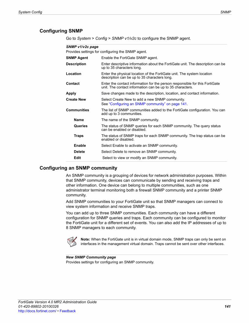
System Config SNMP
F0h
Configuring SNMPGo to System > Config > SNMP v1/v2c to configure the SNMP agent.
Configuring an SNMP communityAn SNMP community is a grouping of devices for network administration purposes. Within that SNMP community, devices can communicate by sending and receiving traps and other information. One device can belong to multiple communities, such as one administrator terminal monitoring both a firewall SNMP community and a printer SNMP community.Add SNMP communities to your FortiGate unit so that SNMP managers can connect to view system information and receive SNMP traps. You can add up to three SNMP communities. Each community can have a different configuration for SNMP queries and traps. Each community can be configured to monitor the FortiGate unit for a different set of events. You can also add the IP addresses of up to 8 SNMP managers to each community.
SNMP v1/v2c pageProvides settings for configuring the SNMP agent.
SNMP Agent Enable the FortiGate SNMP agent.
Description Enter descriptive information about the FortiGate unit. The description can be up to 35 characters long.
Location Enter the physical location of the FortiGate unit. The system location description can be up to 35 characters long.
Contact Enter the contact information for the person responsible for this FortiGate unit. The contact information can be up to 35 characters.
Apply Save changes made to the description, location, and contact information.
Create New Select Create New to add a new SNMP community.See “Configuring an SNMP community” on page 141.
Communities The list of SNMP communities added to the FortiGate configuration. You can add up to 3 communities.
Name The name of the SNMP community.
Queries The status of SNMP queries for each SNMP community. The query status can be enabled or disabled.
Traps The status of SNMP traps for each SNMP community. The trap status can be enabled or disabled.
Enable Select Enable to activate an SNMP community.
Delete Select Delete to remove an SNMP community.
Edit Select to view or modify an SNMP community.
Note: When the FortiGate unit is in virtual domain mode, SNMP traps can only be sent on interfaces in the management virtual domain. Traps cannot be sent over other interfaces.
New SNMP Community pageProvides settings for configuring an SNMP community.
ortiGate Version 4.0 MR2 Administration Guide1-420-89802-20100326 141ttp://docs.fortinet.com/ • Feedback
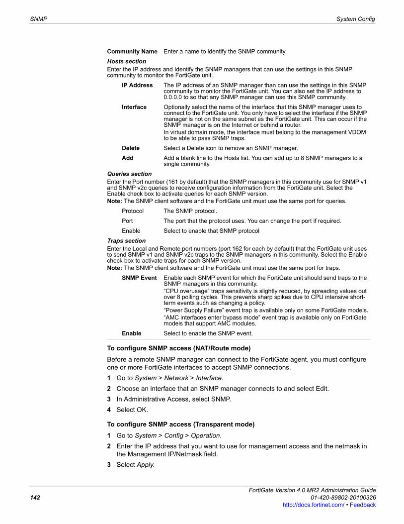
SNMP System Config
To configure SNMP access (NAT/Route mode)Before a remote SNMP manager can connect to the FortiGate agent, you must configure one or more FortiGate interfaces to accept SNMP connections.1 Go to System > Network > Interface.2 Choose an interface that an SNMP manager connects to and select Edit.3 In Administrative Access, select SNMP.4 Select OK.
To configure SNMP access (Transparent mode)1 Go to System > Config > Operation.2 Enter the IP address that you want to use for management access and the netmask in
the Management IP/Netmask field.3 Select Apply.
Community Name Enter a name to identify the SNMP community.
Hosts section Enter the IP address and Identify the SNMP managers that can use the settings in this SNMP community to monitor the FortiGate unit.
IP Address The IP address of an SNMP manager than can use the settings in this SNMP community to monitor the FortiGate unit. You can also set the IP address to 0.0.0.0 to so that any SNMP manager can use this SNMP community.
Interface Optionally select the name of the interface that this SNMP manager uses to connect to the FortiGate unit. You only have to select the interface if the SNMP manager is not on the same subnet as the FortiGate unit. This can occur if the SNMP manager is on the Internet or behind a router.In virtual domain mode, the interface must belong to the management VDOM to be able to pass SNMP traps.
Delete Select a Delete icon to remove an SNMP manager.
Add Add a blank line to the Hosts list. You can add up to 8 SNMP managers to a single community.
Queries section Enter the Port number (161 by default) that the SNMP managers in this community use for SNMP v1 and SNMP v2c queries to receive configuration information from the FortiGate unit. Select the Enable check box to activate queries for each SNMP version.Note: The SNMP client software and the FortiGate unit must use the same port for queries.
Protocol The SNMP protocol.
Port The port that the protocol uses. You can change the port if required.
Enable Select to enable that SNMP protocol
Traps section Enter the Local and Remote port numbers (port 162 for each by default) that the FortiGate unit uses to send SNMP v1 and SNMP v2c traps to the SNMP managers in this community. Select the Enable check box to activate traps for each SNMP version.Note: The SNMP client software and the FortiGate unit must use the same port for traps.
SNMP Event Enable each SNMP event for which the FortiGate unit should send traps to the SNMP managers in this community.“CPU overusage” traps sensitivity is slightly reduced, by spreading values out over 8 polling cycles. This prevents sharp spikes due to CPU intensive short-term events such as changing a policy.“Power Supply Failure” event trap is available only on some FortiGate models.“AMC interfaces enter bypass mode” event trap is available only on FortiGate models that support AMC modules.
Enable Select to enable the SNMP event.
FortiGate Version 4.0 MR2 Administration Guide142 01-420-89802-20100326
http://docs.fortinet.com/ • Feedback
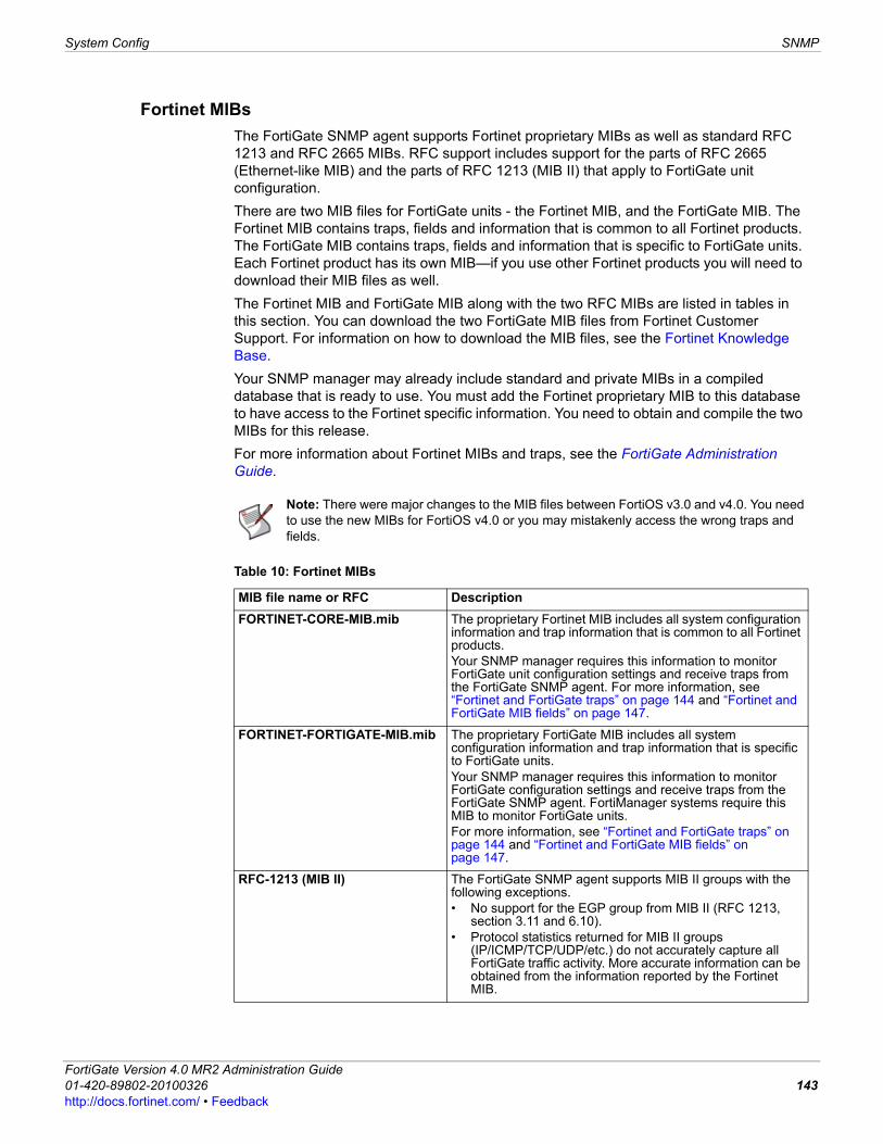
System Config SNMP
F0h
Fortinet MIBsThe FortiGate SNMP agent supports Fortinet proprietary MIBs as well as standard RFC 1213 and RFC 2665 MIBs. RFC support includes support for the parts of RFC 2665 (Ethernet-like MIB) and the parts of RFC 1213 (MIB II) that apply to FortiGate unit configuration. There are two MIB files for FortiGate units - the Fortinet MIB, and the FortiGate MIB. The Fortinet MIB contains traps, fields and information that is common to all Fortinet products. The FortiGate MIB contains traps, fields and information that is specific to FortiGate units. Each Fortinet product has its own MIB—if you use other Fortinet products you will need to download their MIB files as well.The Fortinet MIB and FortiGate MIB along with the two RFC MIBs are listed in tables in this section. You can download the two FortiGate MIB files from Fortinet Customer Support. For information on how to download the MIB files, see the Fortinet Knowledge Base.Your SNMP manager may already include standard and private MIBs in a compiled database that is ready to use. You must add the Fortinet proprietary MIB to this database to have access to the Fortinet specific information. You need to obtain and compile the two MIBs for this release.For more information about Fortinet MIBs and traps, see the FortiGate Administration Guide.
Note: There were major changes to the MIB files between FortiOS v3.0 and v4.0. You need to use the new MIBs for FortiOS v4.0 or you may mistakenly access the wrong traps and fields.
Table 10: Fortinet MIBs
MIB file name or RFC DescriptionFORTINET-CORE-MIB.mib The proprietary Fortinet MIB includes all system configuration
information and trap information that is common to all Fortinet products. Your SNMP manager requires this information to monitor FortiGate unit configuration settings and receive traps from the FortiGate SNMP agent. For more information, see “Fortinet and FortiGate traps” on page 144 and “Fortinet and FortiGate MIB fields” on page 147.
FORTINET-FORTIGATE-MIB.mib The proprietary FortiGate MIB includes all system configuration information and trap information that is specific to FortiGate units. Your SNMP manager requires this information to monitor FortiGate configuration settings and receive traps from the FortiGate SNMP agent. FortiManager systems require this MIB to monitor FortiGate units.For more information, see “Fortinet and FortiGate traps” on page 144 and “Fortinet and FortiGate MIB fields” on page 147.
RFC-1213 (MIB II) The FortiGate SNMP agent supports MIB II groups with the following exceptions.• No support for the EGP group from MIB II (RFC 1213,
section 3.11 and 6.10).• Protocol statistics returned for MIB II groups
(IP/ICMP/TCP/UDP/etc.) do not accurately capture all FortiGate traffic activity. More accurate information can be obtained from the information reported by the Fortinet MIB.
ortiGate Version 4.0 MR2 Administration Guide1-420-89802-20100326 143ttp://docs.fortinet.com/ • Feedback
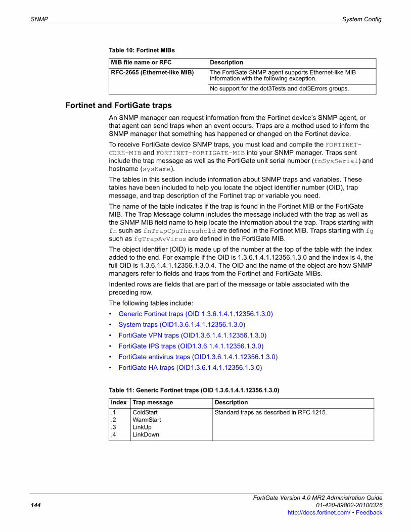
SNMP System Config
Fortinet and FortiGate trapsAn SNMP manager can request information from the Fortinet device’s SNMP agent, or that agent can send traps when an event occurs. Traps are a method used to inform the SNMP manager that something has happened or changed on the Fortinet device.To receive FortiGate device SNMP traps, you must load and compile the FORTINET-CORE-MIB and FORTINET-FORTIGATE-MIB into your SNMP manager. Traps sent include the trap message as well as the FortiGate unit serial number (fnSysSerial) and hostname (sysName).The tables in this section include information about SNMP traps and variables. These tables have been included to help you locate the object identifier number (OID), trap message, and trap description of the Fortinet trap or variable you need.The name of the table indicates if the trap is found in the Fortinet MIB or the FortiGate MIB. The Trap Message column includes the message included with the trap as well as the SNMP MIB field name to help locate the information about the trap. Traps starting with fn such as fnTrapCpuThreshold are defined in the Fortinet MIB. Traps starting with fg such as fgTrapAvVirus are defined in the FortiGate MIB.The object identifier (OID) is made up of the number at the top of the table with the index added to the end. For example if the OID is 1.3.6.1.4.1.12356.1.3.0 and the index is 4, the full OID is 1.3.6.1.4.1.12356.1.3.0.4. The OID and the name of the object are how SNMP managers refer to fields and traps from the Fortinet and FortiGate MIBs.Indented rows are fields that are part of the message or table associated with the preceding row.The following tables include:• Generic Fortinet traps (OID 1.3.6.1.4.1.12356.1.3.0)• System traps (OID1.3.6.1.4.1.12356.1.3.0)• FortiGate VPN traps (OID1.3.6.1.4.1.12356.1.3.0)• FortiGate IPS traps (OID1.3.6.1.4.1.12356.1.3.0)• FortiGate antivirus traps (OID1.3.6.1.4.1.12356.1.3.0)• FortiGate HA traps (OID1.3.6.1.4.1.12356.1.3.0)
RFC-2665 (Ethernet-like MIB) The FortiGate SNMP agent supports Ethernet-like MIB information with the following exception.
No support for the dot3Tests and dot3Errors groups.
Table 10: Fortinet MIBs
MIB file name or RFC Description
Table 11: Generic Fortinet traps (OID 1.3.6.1.4.1.12356.1.3.0)
Index Trap message Description.1.2.3.4
ColdStartWarmStartLinkUpLinkDown
Standard traps as described in RFC 1215.
FortiGate Version 4.0 MR2 Administration Guide144 01-420-89802-20100326
http://docs.fortinet.com/ • Feedback
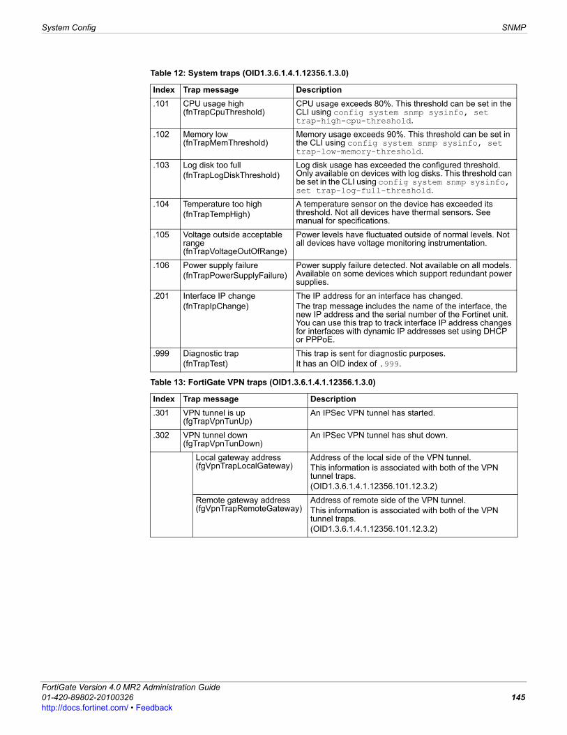
System Config SNMP
F0h
Table 12: System traps (OID1.3.6.1.4.1.12356.1.3.0)
Index Trap message Description.101 CPU usage high
(fnTrapCpuThreshold)CPU usage exceeds 80%. This threshold can be set in the CLI using config system snmp sysinfo, set trap-high-cpu-threshold.
.102 Memory low (fnTrapMemThreshold)
Memory usage exceeds 90%. This threshold can be set in the CLI using config system snmp sysinfo, set trap-low-memory-threshold.
.103 Log disk too full(fnTrapLogDiskThreshold)
Log disk usage has exceeded the configured threshold. Only available on devices with log disks. This threshold can be set in the CLI using config system snmp sysinfo, set trap-log-full-threshold.
.104 Temperature too high(fnTrapTempHigh)
A temperature sensor on the device has exceeded its threshold. Not all devices have thermal sensors. See manual for specifications.
.105 Voltage outside acceptable range (fnTrapVoltageOutOfRange)
Power levels have fluctuated outside of normal levels. Not all devices have voltage monitoring instrumentation.
.106 Power supply failure(fnTrapPowerSupplyFailure)
Power supply failure detected. Not available on all models. Available on some devices which support redundant power supplies.
.201 Interface IP change(fnTrapIpChange)
The IP address for an interface has changed. The trap message includes the name of the interface, the new IP address and the serial number of the Fortinet unit. You can use this trap to track interface IP address changes for interfaces with dynamic IP addresses set using DHCP or PPPoE.
.999 Diagnostic trap(fnTrapTest)
This trap is sent for diagnostic purposes.It has an OID index of .999.
Table 13: FortiGate VPN traps (OID1.3.6.1.4.1.12356.1.3.0)
Index Trap message Description.301 VPN tunnel is up
(fgTrapVpnTunUp)An IPSec VPN tunnel has started.
.302 VPN tunnel down (fgTrapVpnTunDown)
An IPSec VPN tunnel has shut down.
Local gateway address (fgVpnTrapLocalGateway)
Address of the local side of the VPN tunnel. This information is associated with both of the VPN tunnel traps. (OID1.3.6.1.4.1.12356.101.12.3.2)
Remote gateway address (fgVpnTrapRemoteGateway)
Address of remote side of the VPN tunnel.This information is associated with both of the VPN tunnel traps. (OID1.3.6.1.4.1.12356.101.12.3.2)
ortiGate Version 4.0 MR2 Administration Guide1-420-89802-20100326 145ttp://docs.fortinet.com/ • Feedback
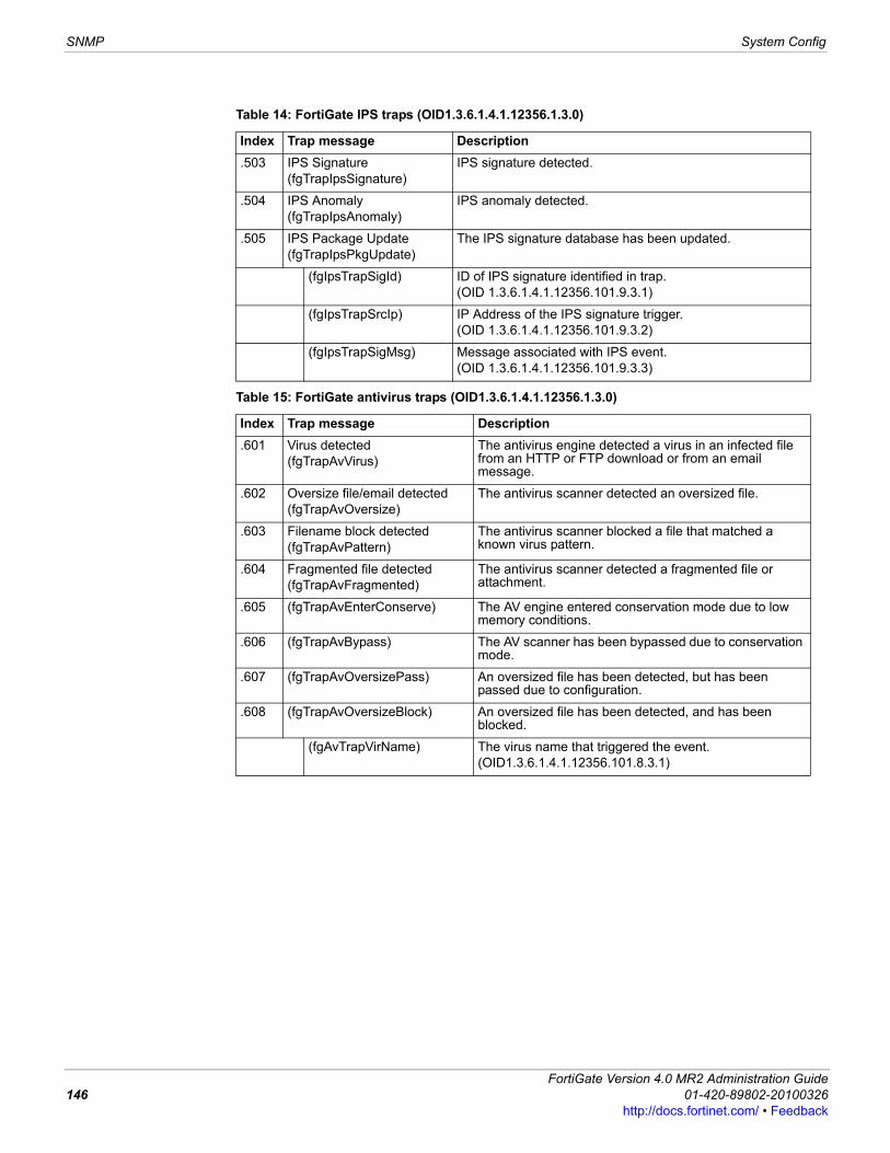
SNMP System Config
Table 14: FortiGate IPS traps (OID1.3.6.1.4.1.12356.1.3.0)
Index Trap message Description.503 IPS Signature
(fgTrapIpsSignature)IPS signature detected.
.504 IPS Anomaly(fgTrapIpsAnomaly)
IPS anomaly detected.
.505 IPS Package Update(fgTrapIpsPkgUpdate)
The IPS signature database has been updated.
(fgIpsTrapSigId) ID of IPS signature identified in trap. (OID 1.3.6.1.4.1.12356.101.9.3.1)
(fgIpsTrapSrcIp) IP Address of the IPS signature trigger. (OID 1.3.6.1.4.1.12356.101.9.3.2)
(fgIpsTrapSigMsg) Message associated with IPS event. (OID 1.3.6.1.4.1.12356.101.9.3.3)
Table 15: FortiGate antivirus traps (OID1.3.6.1.4.1.12356.1.3.0)
Index Trap message Description.601 Virus detected
(fgTrapAvVirus)The antivirus engine detected a virus in an infected file from an HTTP or FTP download or from an email message.
.602 Oversize file/email detected(fgTrapAvOversize)
The antivirus scanner detected an oversized file.
.603 Filename block detected(fgTrapAvPattern)
The antivirus scanner blocked a file that matched a known virus pattern.
.604 Fragmented file detected (fgTrapAvFragmented)
The antivirus scanner detected a fragmented file or attachment.
.605 (fgTrapAvEnterConserve) The AV engine entered conservation mode due to low memory conditions.
.606 (fgTrapAvBypass) The AV scanner has been bypassed due to conservation mode.
.607 (fgTrapAvOversizePass) An oversized file has been detected, but has been passed due to configuration.
.608 (fgTrapAvOversizeBlock) An oversized file has been detected, and has been blocked.
(fgAvTrapVirName) The virus name that triggered the event.(OID1.3.6.1.4.1.12356.101.8.3.1)
FortiGate Version 4.0 MR2 Administration Guide146 01-420-89802-20100326
http://docs.fortinet.com/ • Feedback
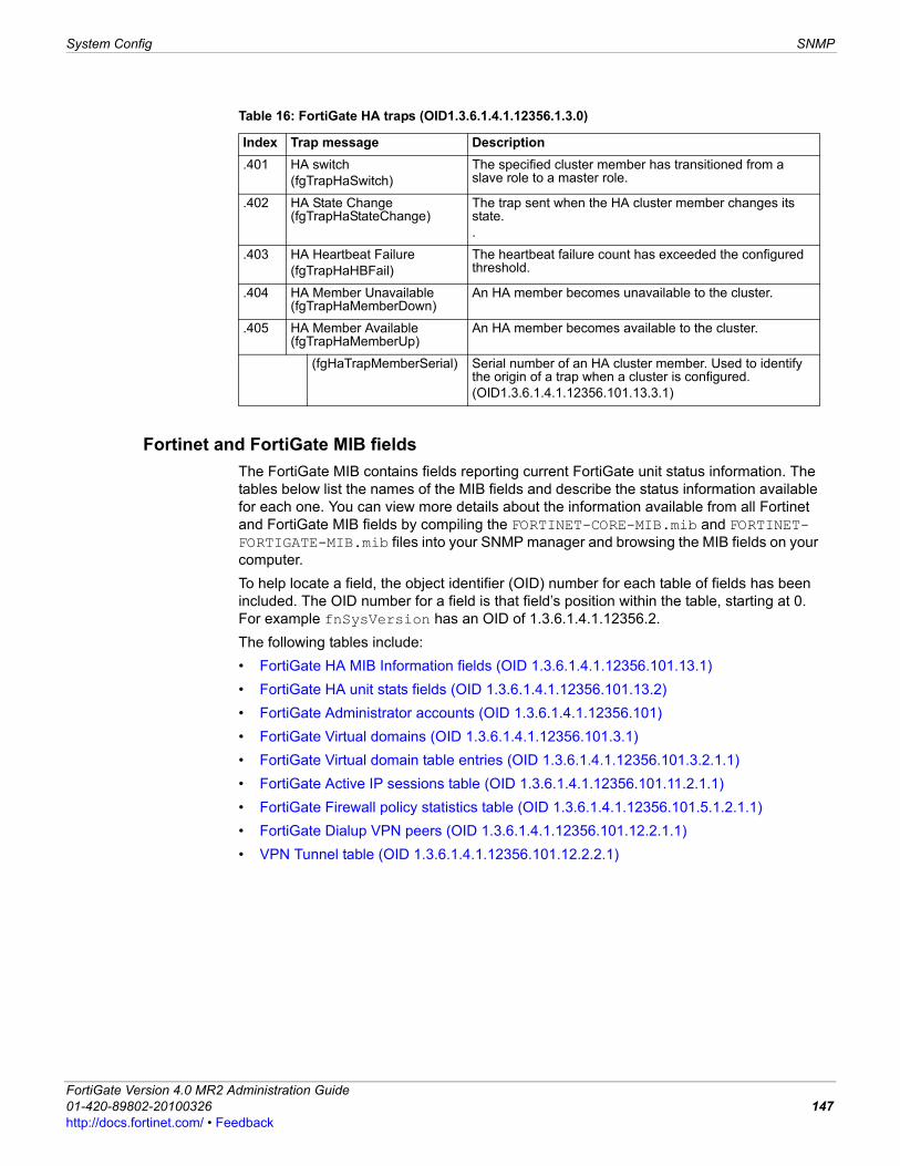
System Config SNMP
F0h
Fortinet and FortiGate MIB fieldsThe FortiGate MIB contains fields reporting current FortiGate unit status information. The tables below list the names of the MIB fields and describe the status information available for each one. You can view more details about the information available from all Fortinet and FortiGate MIB fields by compiling the FORTINET-CORE-MIB.mib and FORTINET-FORTIGATE-MIB.mib files into your SNMP manager and browsing the MIB fields on your computer.To help locate a field, the object identifier (OID) number for each table of fields has been included. The OID number for a field is that field’s position within the table, starting at 0. For example fnSysVersion has an OID of 1.3.6.1.4.1.12356.2.The following tables include:• FortiGate HA MIB Information fields (OID 1.3.6.1.4.1.12356.101.13.1)• FortiGate HA unit stats fields (OID 1.3.6.1.4.1.12356.101.13.2)• FortiGate Administrator accounts (OID 1.3.6.1.4.1.12356.101)• FortiGate Virtual domains (OID 1.3.6.1.4.1.12356.101.3.1)• FortiGate Virtual domain table entries (OID 1.3.6.1.4.1.12356.101.3.2.1.1)• FortiGate Active IP sessions table (OID 1.3.6.1.4.1.12356.101.11.2.1.1)• FortiGate Firewall policy statistics table (OID 1.3.6.1.4.1.12356.101.5.1.2.1.1)• FortiGate Dialup VPN peers (OID 1.3.6.1.4.1.12356.101.12.2.1.1)• VPN Tunnel table (OID 1.3.6.1.4.1.12356.101.12.2.2.1)
Table 16: FortiGate HA traps (OID1.3.6.1.4.1.12356.1.3.0)
Index Trap message Description.401 HA switch
(fgTrapHaSwitch)The specified cluster member has transitioned from a slave role to a master role.
.402 HA State Change (fgTrapHaStateChange)
The trap sent when the HA cluster member changes its state..
.403 HA Heartbeat Failure(fgTrapHaHBFail)
The heartbeat failure count has exceeded the configured threshold.
.404 HA Member Unavailable (fgTrapHaMemberDown)
An HA member becomes unavailable to the cluster.
.405 HA Member Available (fgTrapHaMemberUp)
An HA member becomes available to the cluster.
(fgHaTrapMemberSerial) Serial number of an HA cluster member. Used to identify the origin of a trap when a cluster is configured. (OID1.3.6.1.4.1.12356.101.13.3.1)
ortiGate Version 4.0 MR2 Administration Guide1-420-89802-20100326 147ttp://docs.fortinet.com/ • Feedback
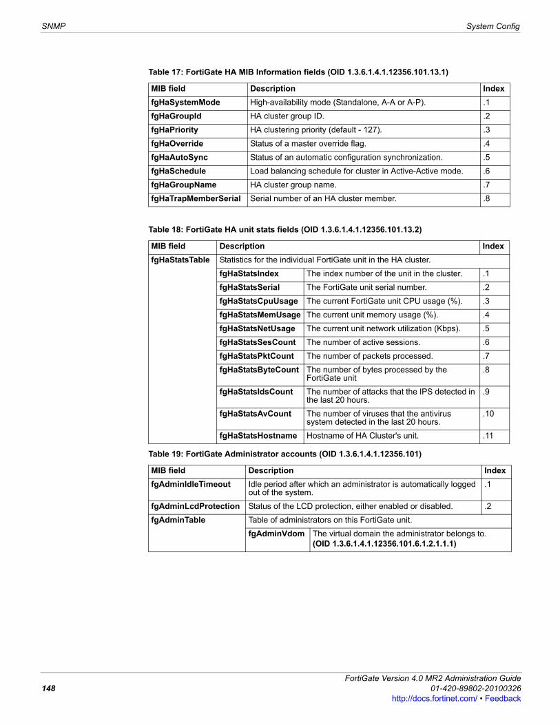
SNMP System Config
Table 17: FortiGate HA MIB Information fields (OID 1.3.6.1.4.1.12356.101.13.1)
MIB field Description IndexfgHaSystemMode High-availability mode (Standalone, A-A or A-P). .1
fgHaGroupId HA cluster group ID. .2
fgHaPriority HA clustering priority (default - 127). .3
fgHaOverride Status of a master override flag. .4
fgHaAutoSync Status of an automatic configuration synchronization. .5
fgHaSchedule Load balancing schedule for cluster in Active-Active mode. .6
fgHaGroupName HA cluster group name. .7
fgHaTrapMemberSerial Serial number of an HA cluster member. .8
Table 18: FortiGate HA unit stats fields (OID 1.3.6.1.4.1.12356.101.13.2)
MIB field Description IndexfgHaStatsTable Statistics for the individual FortiGate unit in the HA cluster.
fgHaStatsIndex The index number of the unit in the cluster. .1
fgHaStatsSerial The FortiGate unit serial number. .2
fgHaStatsCpuUsage The current FortiGate unit CPU usage (%). .3
fgHaStatsMemUsage The current unit memory usage (%). .4
fgHaStatsNetUsage The current unit network utilization (Kbps). .5
fgHaStatsSesCount The number of active sessions. .6
fgHaStatsPktCount The number of packets processed. .7
fgHaStatsByteCount The number of bytes processed by the FortiGate unit
.8
fgHaStatsIdsCount The number of attacks that the IPS detected in the last 20 hours.
.9
fgHaStatsAvCount The number of viruses that the antivirus system detected in the last 20 hours.
.10
fgHaStatsHostname Hostname of HA Cluster's unit. .11
Table 19: FortiGate Administrator accounts (OID 1.3.6.1.4.1.12356.101)
MIB field Description IndexfgAdminIdleTimeout Idle period after which an administrator is automatically logged
out of the system..1
fgAdminLcdProtection Status of the LCD protection, either enabled or disabled. .2
fgAdminTable Table of administrators on this FortiGate unit.
fgAdminVdom The virtual domain the administrator belongs to.(OID 1.3.6.1.4.1.12356.101.6.1.2.1.1.1)
FortiGate Version 4.0 MR2 Administration Guide148 01-420-89802-20100326
http://docs.fortinet.com/ • Feedback
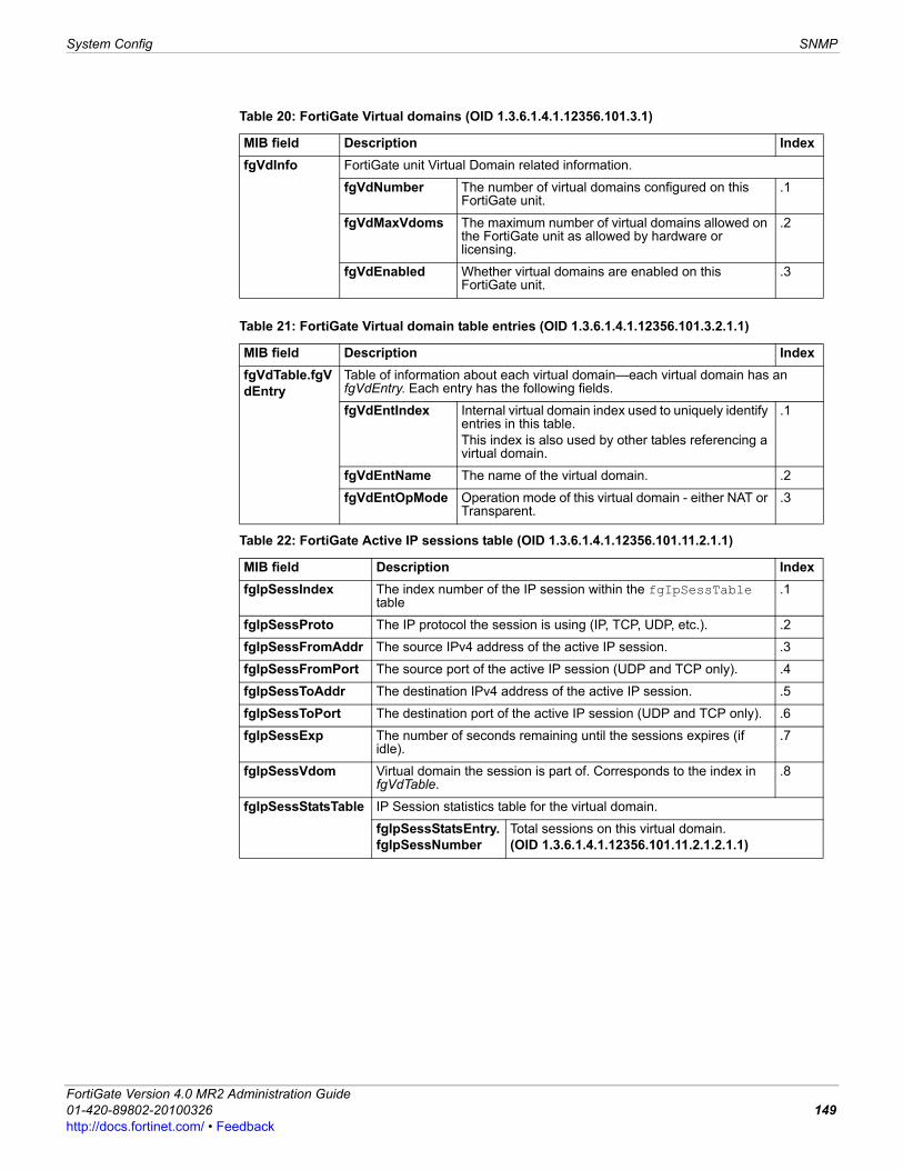
System Config SNMP
F0h
Table 20: FortiGate Virtual domains (OID 1.3.6.1.4.1.12356.101.3.1)
MIB field Description IndexfgVdInfo FortiGate unit Virtual Domain related information.
fgVdNumber The number of virtual domains configured on this FortiGate unit.
.1
fgVdMaxVdoms The maximum number of virtual domains allowed on the FortiGate unit as allowed by hardware or licensing.
.2
fgVdEnabled Whether virtual domains are enabled on this FortiGate unit.
.3
Table 21: FortiGate Virtual domain table entries (OID 1.3.6.1.4.1.12356.101.3.2.1.1)
MIB field Description IndexfgVdTable.fgVdEntry
Table of information about each virtual domain—each virtual domain has an fgVdEntry. Each entry has the following fields.
fgVdEntIndex Internal virtual domain index used to uniquely identify entries in this table. This index is also used by other tables referencing a virtual domain.
.1
fgVdEntName The name of the virtual domain. .2
fgVdEntOpMode Operation mode of this virtual domain - either NAT or Transparent.
.3
Table 22: FortiGate Active IP sessions table (OID 1.3.6.1.4.1.12356.101.11.2.1.1)
MIB field Description IndexfgIpSessIndex The index number of the IP session within the fgIpSessTable
table.1
fgIpSessProto The IP protocol the session is using (IP, TCP, UDP, etc.). .2
fgIpSessFromAddr The source IPv4 address of the active IP session. .3
fgIpSessFromPort The source port of the active IP session (UDP and TCP only). .4
fgIpSessToAddr The destination IPv4 address of the active IP session. .5
fgIpSessToPort The destination port of the active IP session (UDP and TCP only). .6
fgIpSessExp The number of seconds remaining until the sessions expires (if idle).
.7
fgIpSessVdom Virtual domain the session is part of. Corresponds to the index in fgVdTable.
.8
fgIpSessStatsTable IP Session statistics table for the virtual domain.
fgIpSessStatsEntry.fgIpSessNumber
Total sessions on this virtual domain.(OID 1.3.6.1.4.1.12356.101.11.2.1.2.1.1)
ortiGate Version 4.0 MR2 Administration Guide1-420-89802-20100326 149ttp://docs.fortinet.com/ • Feedback
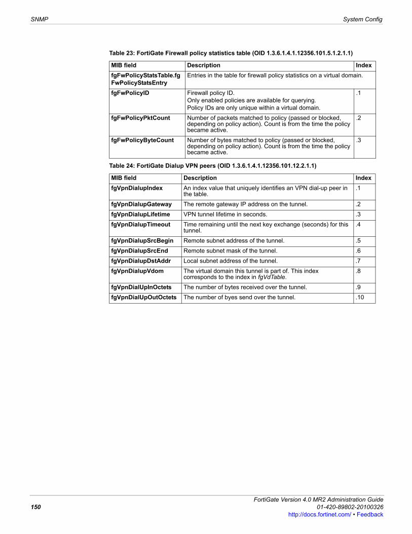
SNMP System Config
Table 23: FortiGate Firewall policy statistics table (OID 1.3.6.1.4.1.12356.101.5.1.2.1.1)
MIB field Description IndexfgFwPolicyStatsTable.fgFwPolicyStatsEntry
Entries in the table for firewall policy statistics on a virtual domain.
fgFwPolicyID Firewall policy ID. Only enabled policies are available for querying.Policy IDs are only unique within a virtual domain.
.1
fgFwPolicyPktCount Number of packets matched to policy (passed or blocked, depending on policy action). Count is from the time the policy became active.
.2
fgFwPolicyByteCount Number of bytes matched to policy (passed or blocked, depending on policy action). Count is from the time the policy became active.
.3
Table 24: FortiGate Dialup VPN peers (OID 1.3.6.1.4.1.12356.101.12.2.1.1)
MIB field Description IndexfgVpnDialupIndex An index value that uniquely identifies an VPN dial-up peer in
the table..1
fgVpnDialupGateway The remote gateway IP address on the tunnel. .2
fgVpnDialupLifetime VPN tunnel lifetime in seconds. .3
fgVpnDialupTimeout Time remaining until the next key exchange (seconds) for this tunnel.
.4
fgVpnDialupSrcBegin Remote subnet address of the tunnel. .5
fgVpnDialupSrcEnd Remote subnet mask of the tunnel. .6
fgVpnDialupDstAddr Local subnet address of the tunnel. .7
fgVpnDialupVdom The virtual domain this tunnel is part of. This index corresponds to the index in fgVdTable.
.8
fgVpnDialUpInOctets The number of bytes received over the tunnel. .9
fgVpnDialUpOutOctets The number of byes send over the tunnel. .10
FortiGate Version 4.0 MR2 Administration Guide150 01-420-89802-20100326
http://docs.fortinet.com/ • Feedback

System Config Replacement messages
F0h
Replacement messagesThe FortiGate unit adds replacement messages to a variety of content streams. For example, if a virus is found in an email message attachment, the file is removed from the email and replaced with a replacement message. The same applies to pages blocked by web filtering and email blocked by email filtering.Go to System > Config > Replacement Message to change replacement messages and customize alert email and information that the FortiGate unit adds to content streams such as email messages, web pages, and FTP sessions.
Table 25: VPN Tunnel table (OID 1.3.6.1.4.1.12356.101.12.2.2.1)
MIB field Description IndexfgVpnTunEntIndex An index value that uniquely identifies a VPN tunnel
within the VPN tunnel table. .1
fgVpnTunEntPhase1Name The descriptive name of the Phase1 configuration for the tunnel.
.2
fgVpnTunEntPhase2Name The descriptive name of the Phase2 configuration for the tunnel.
.3
fgVpnTunEntRemGwyIp The IP of the remote gateway used by the tunnel. .4
fgVpnTunEntRemGwyPort The port of the remote gateway used by the tunnel, if it is UDP.
.5
fgVpnTunEntLocGwyIp The IP of the local gateway used by the tunnel. .6
fgVpnTunEntLocGwyPort The port of the local gateway used by the tunnel, if it is UDP.
.7
fgVpnTunEntSelectorSrcBeginIp
Beginning of the address range of the source selector. .8
fgVpnTunEntSelectorSrcEndIp Ending of the address range of the source selector. .9
fgVpnTunEntSelectorSrcPort Source selector port. .10
fgVpnTunEntSelectorDstBeginIp
Beginning of the address range of the destination selector.
.11
fgVpnTunEntSelectorDstEndIp Ending of the address range of the destination selector. .12
fgVpnTunEntSelectorDstPort Destination selector port. .13
fgVpnTunEntSelectorProto Protocol number for the selector. .14
fgVpnTunEntLifeSecs Lifetime of the tunnel in seconds, if time based lifetime is used.
.15
fgVpnTunEntLifeBytes Lifetime of the tunnel in bytes, if byte transfer based lifetime is used.
.16
fgVpnTunEntTimeout Timeout of the tunnel in seconds. .17
fgVpnTunEntInOctets Number of bytes received on the tunnel. .18
fgVpnTunEntOutOctets Number of bytes sent out on the tunnel. .19
fgVpnTunEntStatus Current status of the tunnel - either up or down. .20
fgVpnTunEntVdom Virtual domain the tunnel belongs to. This index corresponds to the index used in fgVdTable.
.21
Note: Disclaimer replacement messages provided by Fortinet are examples only.
ortiGate Version 4.0 MR2 Administration Guide1-420-89802-20100326 151ttp://docs.fortinet.com/ • Feedback
Replacement messages System Config
• VDOM and global replacement messages
VDOM and global replacement messagesFortiGate units include global replacement messages that are used by all VDOMs. At the global level you can customize replacement messages or reset modified messages to their factory defaults. If you decide to revert a customized message to the default message you can view the customized message in the replacement messages list and select a Reset icon to revert the message to the default version.In each VDOM you can customize any replacement message for that VDOM as needed, overriding the global message. If you decide to revert a customized message to the global message you can view the customized message in the replacement messages list and select a Reset icon to revert the message to use the global version of this message.
Viewing the replacement messages listTo view the replacement messages list go to System > Config > Replacement Message You use the replacement messages list to view and customize replacement messages to your requirements. The list organizes replacement message into an number of types (for example, Mail, HTTP, and so on). Use the expand arrow beside each type to display the replacement messages for that category. Select the Edit icon beside each replacement message to customize that message for your requirements.If you are viewing the replacement messages list in a VDOM, any messages that have been customized for that VDOM are displayed with a Reset icon that you can use to reset the replacement message to the global version.
See also• Changing replacement messages• VDOM and global replacement messages•
Replacement Messages pageLists the replacement messages and are grouped by their associated FortiOS feature. For example, virus message is placed in the Mail group.
Name The replacement message category. Select the expand arrow to expand or collapse the category. Each category contains several replacement messages that are used by different FortiGate features. The replacement messages are described below.
Description A description of the replacement message.
Edit Select to change or view a replacement message.
Reset Only displayed on the a VDOM replacement message list. Select to revert to the global version of this replacement message.
Note: FortiOS uses HTTP to send the Authentication Disclaimer page for the user to accept before the firewall policy is in effect. Therefore, the user must initiate HTTP traffic first in order to trigger the Authentication Disclaimer page. Once the Disclaimer is accepted, the user can send whatever traffic is allowed by the firewall policy.
FortiGate Version 4.0 MR2 Administration Guide152 01-420-89802-20100326
http://docs.fortinet.com/ • Feedback
System Config Replacement messages
F0h
Changing replacement messagesTo change a replacement message list go to System > Config > Replacement Message. Use the expand arrows to view the replacement message that you want to change. You can change the content of the replacement message by editing the text and HTML codes and by working with replacement message tags. For descriptions of the replacement message tags, see Table 36 on page 162.Replacement messages can be text or HTML messages. You can add HTML code to HTML messages. Allowed Formats shows you which format to use in the replacement message. There is a limit of 8192 characters for each replacement message. The following fields and options are available when editing a replacement message. Different replacement messages have different sets of fields and options.
You can customize the following categories of replacement messages:
Mail replacement messagesThe FortiGate unit sends the mail replacement messages listed in Table 26 to email clients and servers using IMAP, POP3, or SMTP when an event occurs such as antivirus blocking a file attached to an email that contains a virus. Email replacement messages are text messages.If the FortiGate unit supports SSL content scanning and inspection these replacement messages can also be added to IMAPS, POP3S, and SMTPS email messages. For more information, see the UTM chapter of the FortiOS Handbook.
The replacement message page of a replacement messageMessage Setup The name of the replacement message.
Allowed Formats The type of content that can be included in the replacement message. Allowed formats can be Text or HTML. You should not use HTML code in Text messages. You can include replacement message tags in text and HTML messages.
Size The number of characters allowed in the replacement message. Usually size is 8192 characters.
Message Text The editable text of the replacement message. The message text can include text, HTML codes (if HTML is the allowed format) and replacement message tags.
ortiGate Version 4.0 MR2 Administration Guide1-420-89802-20100326 153ttp://docs.fortinet.com/ • Feedback
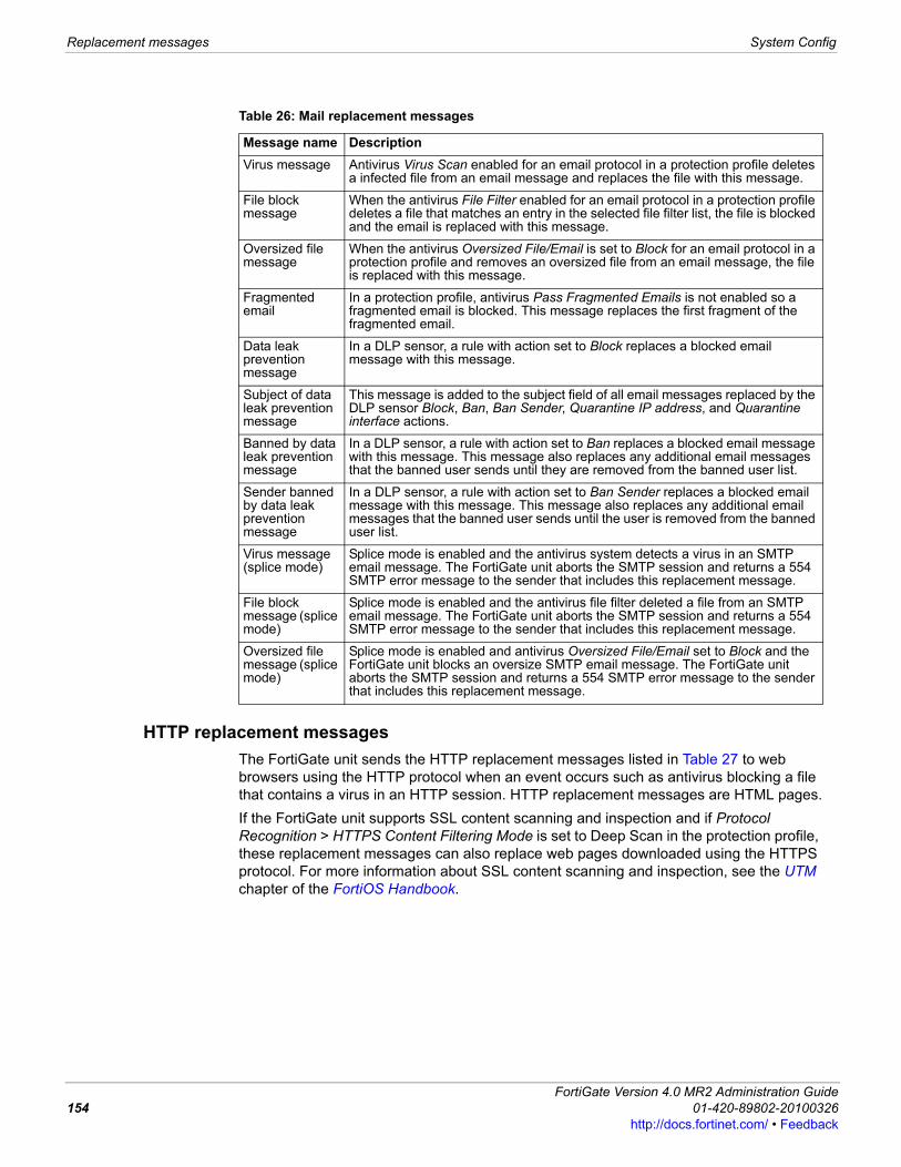
Replacement messages System Config
HTTP replacement messagesThe FortiGate unit sends the HTTP replacement messages listed in Table 27 to web browsers using the HTTP protocol when an event occurs such as antivirus blocking a file that contains a virus in an HTTP session. HTTP replacement messages are HTML pages.If the FortiGate unit supports SSL content scanning and inspection and if Protocol Recognition > HTTPS Content Filtering Mode is set to Deep Scan in the protection profile, these replacement messages can also replace web pages downloaded using the HTTPS protocol. For more information about SSL content scanning and inspection, see the UTM chapter of the FortiOS Handbook.
Table 26: Mail replacement messages
Message name DescriptionVirus message Antivirus Virus Scan enabled for an email protocol in a protection profile deletes
a infected file from an email message and replaces the file with this message.
File block message
When the antivirus File Filter enabled for an email protocol in a protection profile deletes a file that matches an entry in the selected file filter list, the file is blocked and the email is replaced with this message.
Oversized file message
When the antivirus Oversized File/Email is set to Block for an email protocol in a protection profile and removes an oversized file from an email message, the file is replaced with this message.
Fragmented email
In a protection profile, antivirus Pass Fragmented Emails is not enabled so a fragmented email is blocked. This message replaces the first fragment of the fragmented email.
Data leak prevention message
In a DLP sensor, a rule with action set to Block replaces a blocked email message with this message.
Subject of data leak prevention message
This message is added to the subject field of all email messages replaced by the DLP sensor Block, Ban, Ban Sender, Quarantine IP address, and Quarantine interface actions.
Banned by data leak prevention message
In a DLP sensor, a rule with action set to Ban replaces a blocked email message with this message. This message also replaces any additional email messages that the banned user sends until they are removed from the banned user list.
Sender banned by data leak prevention message
In a DLP sensor, a rule with action set to Ban Sender replaces a blocked email message with this message. This message also replaces any additional email messages that the banned user sends until the user is removed from the banned user list.
Virus message (splice mode)
Splice mode is enabled and the antivirus system detects a virus in an SMTP email message. The FortiGate unit aborts the SMTP session and returns a 554 SMTP error message to the sender that includes this replacement message.
File block message (splice mode)
Splice mode is enabled and the antivirus file filter deleted a file from an SMTP email message. The FortiGate unit aborts the SMTP session and returns a 554 SMTP error message to the sender that includes this replacement message.
Oversized file message (splice mode)
Splice mode is enabled and antivirus Oversized File/Email set to Block and the FortiGate unit blocks an oversize SMTP email message. The FortiGate unit aborts the SMTP session and returns a 554 SMTP error message to the sender that includes this replacement message.
FortiGate Version 4.0 MR2 Administration Guide154 01-420-89802-20100326
http://docs.fortinet.com/ • Feedback
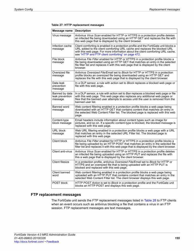
System Config Replacement messages
F0h
FTP replacement messagesThe FortiGate unit sends the FTP replacement messages listed in Table 28 to FTP clients when an event occurs such as antivirus blocking a file that contains a virus in an FTP session. FTP replacement messages are text messages.
Table 27: HTTP replacement messages
Message name DescriptionVirus message Antivirus Virus Scan enabled for HTTP or HTTPS in a protection profile deletes
an infected file being downloaded using an HTTP GET and replaces the file with this web page that is displayed by the client browser.
Infection cache message
Client comforting is enabled in a protection profile and the FortiGate unit blocks a URL added to the client comforting URL cache and replaces the blocked URL with this web page. For more information about the client comforting URL cache, see “HTTP and FTP client comforting” on page 472.
File block message
Antivirus File Filter enabled for HTTP or HTTPS in a protection profile blocks a file being downloaded using an HTTP GET that matches an entry in the selected file filter list and replaces it with this web page that is displayed by the client browser.
Oversized file message
Antivirus Oversized File/Email set to Block for HTTP or HTTPS in a protection profile blocks an oversized file being downloaded using an HTTP GET and replaces the file with this web page that is displayed by the client browser.
Data leak prevention message
In a DLP sensor, a rule with action set to Block replaces a blocked web page or file with this web page.
Banned by data leak prevention message
In a DLP sensor, a rule with action set to Ban replaces a blocked web page or file with this web page. This web page also replaces any additional web pages or files that the banned user attempts to access until the user is removed from the banned user list.
Banned word message
Web content filtering enabled in a protection profile blocks a web page being downloaded with an HTTP GET that contains content that matches an entry in the selected Web Content Filter list. The blocked page is replaced with this web page.
Content-type block message
Email headers include information about content types such as image for pictures, and so on. If a specific content-type is blocked, the blocked message is replaced with this web page.
URL block message
Web URL filtering enabled in a protection profile blocks a web page with a URL that matches an entry in the selected URL Filter list. The blocked page is replaced with this web page.
Client block Antivirus File Filter enabled for HTTP or HTTPS in a protection profile blocks a file being uploaded by an HTTP POST that matches an entry in the selected file filter list and replaces it with this web page that is displayed by the client browser.
Client anti-virus Antivirus Virus Scan enabled for HTTP or HTTPS in a protection profile deletes an infected file being uploaded using an HTTP PUT and replaces the file with this a web page that is displayed by the client browser.
Client filesize In a protection profile, antivirus Oversized File/Email set to Block for HTTP or HTTPS and an oversized file that is being uploaded with an HTTP PUT is blocked and replaced with this web page.
Client banned word
Web content filtering enabled in a protection profile blocks a web page being uploaded with an HTTP PUT that contains content that matches an entry in the selected Web Content Filter list. The client browser displays this web page.
POST block HTTP POST Action is set to Block in a protection profile and the FortiGate unit blocks an HTTP POST and displays this web page.
ortiGate Version 4.0 MR2 Administration Guide1-420-89802-20100326 155ttp://docs.fortinet.com/ • Feedback
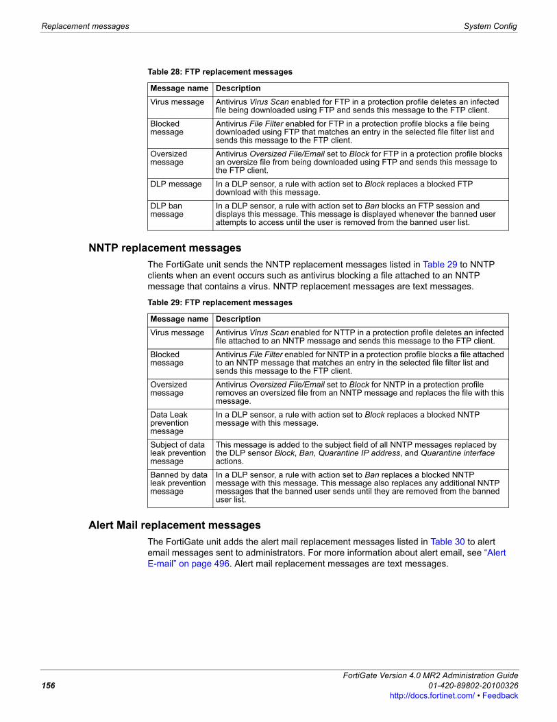
Replacement messages System Config
NNTP replacement messagesThe FortiGate unit sends the NNTP replacement messages listed in Table 29 to NNTP clients when an event occurs such as antivirus blocking a file attached to an NNTP message that contains a virus. NNTP replacement messages are text messages.
Alert Mail replacement messagesThe FortiGate unit adds the alert mail replacement messages listed in Table 30 to alert email messages sent to administrators. For more information about alert email, see “Alert E-mail” on page 496. Alert mail replacement messages are text messages.
Table 28: FTP replacement messages
Message name DescriptionVirus message Antivirus Virus Scan enabled for FTP in a protection profile deletes an infected
file being downloaded using FTP and sends this message to the FTP client.
Blocked message
Antivirus File Filter enabled for FTP in a protection profile blocks a file being downloaded using FTP that matches an entry in the selected file filter list and sends this message to the FTP client.
Oversized message
Antivirus Oversized File/Email set to Block for FTP in a protection profile blocks an oversize file from being downloaded using FTP and sends this message to the FTP client.
DLP message In a DLP sensor, a rule with action set to Block replaces a blocked FTP download with this message.
DLP ban message
In a DLP sensor, a rule with action set to Ban blocks an FTP session and displays this message. This message is displayed whenever the banned user attempts to access until the user is removed from the banned user list.
Table 29: FTP replacement messages
Message name DescriptionVirus message Antivirus Virus Scan enabled for NTTP in a protection profile deletes an infected
file attached to an NNTP message and sends this message to the FTP client.
Blocked message
Antivirus File Filter enabled for NNTP in a protection profile blocks a file attached to an NNTP message that matches an entry in the selected file filter list and sends this message to the FTP client.
Oversized message
Antivirus Oversized File/Email set to Block for NNTP in a protection profile removes an oversized file from an NNTP message and replaces the file with this message.
Data Leak prevention message
In a DLP sensor, a rule with action set to Block replaces a blocked NNTP message with this message.
Subject of data leak prevention message
This message is added to the subject field of all NNTP messages replaced by the DLP sensor Block, Ban, Quarantine IP address, and Quarantine interface actions.
Banned by data leak prevention message
In a DLP sensor, a rule with action set to Ban replaces a blocked NNTP message with this message. This message also replaces any additional NNTP messages that the banned user sends until they are removed from the banned user list.
FortiGate Version 4.0 MR2 Administration Guide156 01-420-89802-20100326
http://docs.fortinet.com/ • Feedback
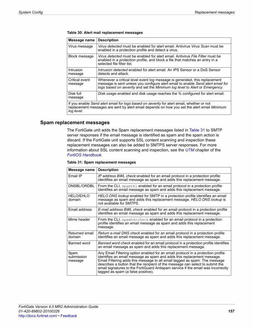
System Config Replacement messages
F0h
Spam replacement messagesThe FortiGate unit adds the Spam replacement messages listed in Table 31 to SMTP server responses if the email message is identified as spam and the spam action is discard. If the FortiGate unit supports SSL content scanning and inspection these replacement messages can also be added to SMTPS server responses. For more information about SSL content scanning and inspection, see the UTM chapter of the FortiOS Handbook.
Table 30: Alert mail replacement messages
Message name DescriptionVirus message Virus detected must be enabled for alert email. Antivirus Virus Scan must be
enabled in a protection profile and detect a virus.
Block message Virus detected must be enabled for alert email. Antivirus File Filter must be enabled in a protection profile, and block a file that matches an entry in a selected file filter list.
Intrusion message
Intrusion detected enabled for alert email. An IPS Sensor or a DoS Sensor detects and attack.
Critical event message
Whenever a critical level event log message is generated, this replacement message is sent unless you configure alert email to enable Send alert email for logs based on severity and set the Minimum log level to Alert or Emergency.
Disk full message
Disk usage enabled and disk usage reaches the % configured for alert email.
If you enable Send alert email for logs based on severity for alert email, whether or not replacement messages are sent by alert email depends on how you set the alert email Minimum log level.
Table 31: Spam replacement messages
Message name DescriptionEmail IP IP address BWL check enabled for an email protocol in a protection profile
identifies an email message as spam and adds this replacement message.
DNSBL/ORDBL From the CLI, spamrbl enabled for an email protocol in a protection profile identifies an email message as spam and adds this replacement message.
HELO/EHLO domain
HELO DNS lookup enabled for SMTP in a protection profile identifies an email message as spam and adds this replacement message. HELO DNS lookup is not available for SMTPS.
Email address E-mail address BWL check enabled for an email protocol in a protection profile identifies an email message as spam and adds this replacement message.
Mime header From the CLI, spamhdrcheck enabled for an email protocol in a protection profile identifies an email message as spam and adds this replacement message.
Returned email domain
Return e-mail DNS check enabled for an email protocol in a protection profile identifies an email message as spam and adds this replacement message.
Banned word Banned word check enabled for an email protocol in a protection profile identifies an email message as spam and adds this replacement message.
Spam submission message
Any Email Filtering option enabled for an email protocol in a protection profile identifies an email message as spam and adds this replacement message. Email Filtering adds this message to all email tagged as spam. The message describes a button that the recipient of the message can select to submit the email signatures to the FortiGuard Antispam service if the email was incorrectly tagged as spam (a false positive).
ortiGate Version 4.0 MR2 Administration Guide1-420-89802-20100326 157ttp://docs.fortinet.com/ • Feedback
Replacement messages System Config
Administration replacement messageIf you enter the following CLI command the FortiGate unit displays the Administration Login disclaimer whenever an administrator logs into the FortiGate unit web-based manager or CLI.
config system globalset access-banner enable
end
The web-based manager administrator login disclaimer contains the text of the Login Disclaimer replacement message as well as Accept and Decline buttons. The administrator must select accept to login.
User authentication replacement messagesThe FortiGate unit uses the text of the authentication replacement messages listed in Table 32 for various user authentication HTML pages that are displayed when a user is required to authenticate because a firewall policy includes at least one identity-based policy that requires firewall users to authenticate. For more information about identity-based policies, see “Configuring identity-based firewall policies” on page 263 and “Configuring SSL VPN identity-based firewall policies” on page 266. These replacement message pages are for authentication using HTTP and HTTPS. Authentication replacement messages are HTML messages. You cannot customize the firewall authentication messages for FTP and Telnet.The authentication login page and the authentication disclaimer include replacement tags and controls not found on other replacement messages.Users see the authentication login page when they use a VPN or a firewall policy that requires authentication. You can customize this page in the same way as you modify other replacement messages.There are some unique requirements for these replacement messages:• The login page must be an HTML page containing a form with ACTION="/" and
METHOD="POST"• The form must contain the following hidden controls:
• <INPUT TYPE="hidden" NAME="%%MAGICID%%" VALUE="%%MAGICVAL%%">
• <INPUT TYPE="hidden" NAME="%%STATEID%%" VALUE="%%STATEVAL%%">
• <INPUT TYPE="hidden" NAME="%%REDIRID%%" VALUE="%%PROTURI%%">
• The form must contain the following visible controls:• <INPUT TYPE="text" NAME="%%USERNAMEID%%" size=25>
• <INPUT TYPE="password" NAME="%%PASSWORDID%%" size=25>
ExampleThe following is an example of a simple authentication page that meets the requirements listed above.
<HTML><HEAD><TITLE>Firewall Authentication</TITLE></HEAD><BODY><H4>You must authenticate to use this service.</H4>
<FORM ACTION="/" method="post"><INPUT NAME="%%MAGICID%%" VALUE="%%MAGICVAL%%" TYPE="hidden">
<TABLE ALIGN="center" BGCOLOR="#00cccc" BORDER="0"CELLPADDING="15" CELLSPACING="0" WIDTH="320"><TBODY>
FortiGate Version 4.0 MR2 Administration Guide158 01-420-89802-20100326
http://docs.fortinet.com/ • Feedback
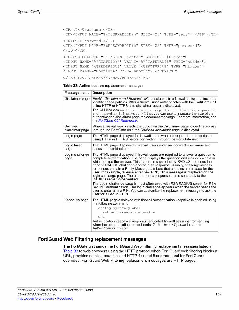
System Config Replacement messages
F0h
<TR><TH>Username:</TH><TD><INPUT NAME="%%USERNAMEID%%" SIZE="25" TYPE="text"> </TD></TR>
<TR><TH>Password:</TH><TD><INPUT NAME="%%PASSWORDID%%" SIZE="25" TYPE="password"> </TD></TR>
<TR><TD COLSPAN="2" ALIGN="center" BGCOLOR="#00cccc"><INPUT NAME="%%STATEID%%" VALUE="%%STATEVAL%%" TYPE="hidden"><INPUT NAME="%%REDIRID%%" VALUE="%%PROTURI%%" TYPE="hidden"><INPUT VALUE="Continue" TYPE="submit"> </TD></TR>
</TBODY></TABLE></FORM></BODY></HTML>
FortiGuard Web Filtering replacement messagesThe FortiGate unit sends the FortiGuard Web Filtering replacement messages listed in Table 33 to web browsers using the HTTP protocol when FortiGuard web filtering blocks a URL, provides details about blocked HTTP 4xx and 5xx errors, and for FortiGuard overrides. FortiGuard Web Filtering replacement messages are HTTP pages.
Table 32: Authentication replacement messages
Message name DescriptionDisclaimer page Enable Disclaimer and Redirect URL to selected in a firewall policy that includes
identity based policies. After a firewall user authenticates with the FortiGate unit using HTTP or HTTPS, this disclaimer page is displayed.The CLI includes auth-disclaimer-page-1, auth-disclaimer-page-2, and auth-disclaimer-page-3 that you can use to increase the size of the authentication disclaimer page replacement message. For more information, see the FortiGate CLI Reference.
Declined disclaimer page
When a firewall user selects the button on the Disclaimer page to decline access through the FortiGate unit, the Declined disclaimer page is displayed.
Login page The HTML page displayed for firewall users who are required to authenticate using HTTP or HTTPS before connecting through the FortiGate unit.
Login failed page
The HTML page displayed if firewall users enter an incorrect user name and password combination.
Login challenge page
The HTML page displayed if firewall users are required to answer a question to complete authentication. The page displays the question and includes a field in which to type the answer. This feature is supported by RADIUS and uses the generic RADIUS challenge-access auth response. Usually, challenge-access responses contain a Reply-Message attribute that contains a message for the user (for example, “Please enter new PIN”). This message is displayed on the login challenge page. The user enters a response that is sent back to the RADIUS server to be verified. The Login challenge page is most often used with RSA RADIUS server for RSA SecurID authentication. The login challenge appears when the server needs the user to enter a new PIN. You can customize the replacement message to ask the user for a SecurID PIN.
Keepalive page The HTML page displayed with firewall authentication keepalive is enabled using the following command:
config system globalset auth-keepalive enable
endAuthentication keepalive keeps authenticated firewall sessions from ending when the authentication timeout ends. Go to User > Options to set the Authentication Timeout.
ortiGate Version 4.0 MR2 Administration Guide1-420-89802-20100326 159ttp://docs.fortinet.com/ • Feedback
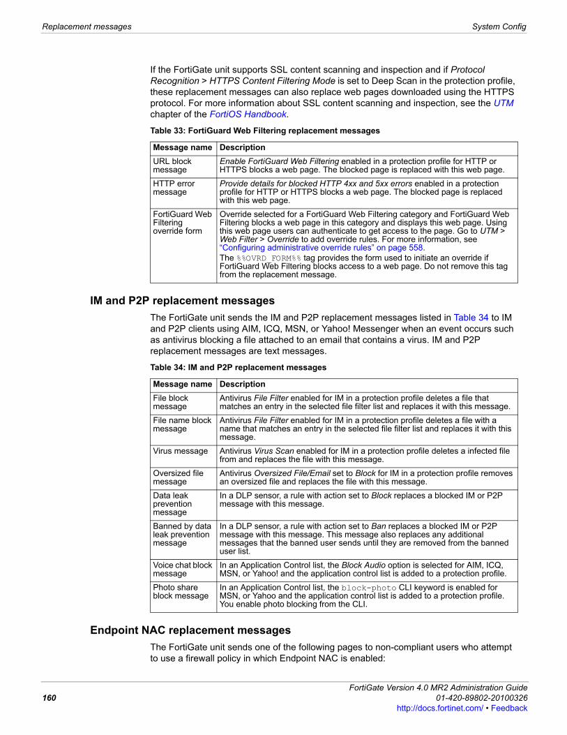
Replacement messages System Config
If the FortiGate unit supports SSL content scanning and inspection and if Protocol Recognition > HTTPS Content Filtering Mode is set to Deep Scan in the protection profile, these replacement messages can also replace web pages downloaded using the HTTPS protocol. For more information about SSL content scanning and inspection, see the UTM chapter of the FortiOS Handbook.
IM and P2P replacement messagesThe FortiGate unit sends the IM and P2P replacement messages listed in Table 34 to IM and P2P clients using AIM, ICQ, MSN, or Yahoo! Messenger when an event occurs such as antivirus blocking a file attached to an email that contains a virus. IM and P2P replacement messages are text messages.
Endpoint NAC replacement messagesThe FortiGate unit sends one of the following pages to non-compliant users who attempt to use a firewall policy in which Endpoint NAC is enabled:
Table 33: FortiGuard Web Filtering replacement messages
Message name DescriptionURL block message
Enable FortiGuard Web Filtering enabled in a protection profile for HTTP or HTTPS blocks a web page. The blocked page is replaced with this web page.
HTTP error message
Provide details for blocked HTTP 4xx and 5xx errors enabled in a protection profile for HTTP or HTTPS blocks a web page. The blocked page is replaced with this web page.
FortiGuard Web Filtering override form
Override selected for a FortiGuard Web Filtering category and FortiGuard Web Filtering blocks a web page in this category and displays this web page. Using this web page users can authenticate to get access to the page. Go to UTM > Web Filter > Override to add override rules. For more information, see “Configuring administrative override rules” on page 558.The %%OVRD_FORM%% tag provides the form used to initiate an override if FortiGuard Web Filtering blocks access to a web page. Do not remove this tag from the replacement message.
Table 34: IM and P2P replacement messages
Message name DescriptionFile block message
Antivirus File Filter enabled for IM in a protection profile deletes a file that matches an entry in the selected file filter list and replaces it with this message.
File name block message
Antivirus File Filter enabled for IM in a protection profile deletes a file with a name that matches an entry in the selected file filter list and replaces it with this message.
Virus message Antivirus Virus Scan enabled for IM in a protection profile deletes a infected file from and replaces the file with this message.
Oversized file message
Antivirus Oversized File/Email set to Block for IM in a protection profile removes an oversized file and replaces the file with this message.
Data leak prevention message
In a DLP sensor, a rule with action set to Block replaces a blocked IM or P2P message with this message.
Banned by data leak prevention message
In a DLP sensor, a rule with action set to Ban replaces a blocked IM or P2P message with this message. This message also replaces any additional messages that the banned user sends until they are removed from the banned user list.
Voice chat block message
In an Application Control list, the Block Audio option is selected for AIM, ICQ, MSN, or Yahoo! and the application control list is added to a protection profile.
Photo share block message
In an Application Control list, the block-photo CLI keyword is enabled for MSN, or Yahoo and the application control list is added to a protection profile. You enable photo blocking from the CLI.
FortiGate Version 4.0 MR2 Administration Guide160 01-420-89802-20100326
http://docs.fortinet.com/ • Feedback
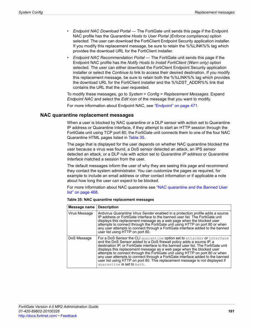
System Config Replacement messages
F0h
• Endpoint NAC Download Portal — The FortiGate unit sends this page if the Endpoint NAC profile has the Quarantine Hosts to User Portal (Enforce compliance) option selected. The user can download the FortiClient Endpoint Security application installer. If you modify this replacement message, be sure to retain the %%LINK%% tag which provides the download URL for the FortiClient installer.
• Endpoint NAC Recommendation Portal — The FortiGate unit sends this page if the Endpoint NAC profile has the Notify Hosts to Install FortiClient (Warn only) option selected. The user can either download the FortiClient Endpoint Security application installer or select the Continue to link to access their desired destination. If you modify this replacement message, be sure to retain both the %%LINK%% tag which provides the download URL for the FortiClient installer and the %%DST_ADDR%% link that contains the URL that the user requested.
To modify these messages, go to System > Config > Replacement Messages. Expand Endpoint NAC and select the Edit icon of the message that you want to modify.For more information about Endpoint NAC, see “Endpoint” on page 471.
NAC quarantine replacement messagesWhen a user is blocked by NAC quarantine or a DLP sensor with action set to Quarantine IP address or Quarantine Interface, if they attempt to start an HTTP session through the FortiGate unit using TCP port 80, the FortiGate unit connects them to one of the four NAC Quarantine HTML pages listed in Table 35.The page that is displayed for the user depends on whether NAC quarantine blocked the user because a virus was found, a DoS sensor detected an attack, an IPS sensor detected an attack, or a DLP rule with action set to Quarantine IP address or Quarantine Interface matched a session from the user.The default messages inform the user of why they are seeing this page and recommend they contact the system administrator. You can customize the pages as required, for example to include an email address or other contact information or if applicable a note about how long the user can expect to be blocked.For more information about NAC quarantine see “NAC quarantine and the Banned User list” on page 468.
Table 35: NAC quarantine replacement messages
Message name DescriptionVirus Message Antivirus Quarantine Virus Sender enabled in a protection profile adds a source
IP address or FortiGate interface to the banned user list. The FortiGate unit displays this replacement message as a web page when the blocked user attempts to connect through the FortiGate unit using HTTP on port 80 or when any user attempts to connect through a FortiGate interface added to the banned user list using HTTP on port 80.
DoS Message For a DoS Sensor the CLI quarantine option set to attacker or interface and the DoS Sensor added to a DoS firewall policy adds a source IP, a destination IP, or FortiGate interface to the banned user list. The FortiGate unit displays this replacement message as a web page when the blocked user attempts to connect through the FortiGate unit using HTTP on port 80 or when any user attempts to connect through a FortiGate interface added to the banned user list using HTTP on port 80. This replacement message is not displayed if quarantine is set to both.
ortiGate Version 4.0 MR2 Administration Guide1-420-89802-20100326 161ttp://docs.fortinet.com/ • Feedback

Replacement messages System Config
Traffic quota control replacement messagesWhen user traffic going through the FortiGate unit is blocked by traffic shaping quota controls, users see the Traffic shaper block message or the Per IP traffic shaper block message when they attempt to connect through the FortiGate unit using HTTP. The traffic quota HTTP pages should contain the %%QUOTA_INFO%% tag to display information about the traffic shaping quota setting that is blocking the user.For information about traffic quotas, see “” on page 323.
SSL VPN replacement messageThe SSL VPN login replacement message is an HTML replacement message that formats the FortiGate SSL VPN portal login page. You can customize this replacement message according to your organization’s needs. The page is linked to FortiGate functionality and you must construct it according to the following guidelines to ensure that it will work.• The login page must be an HTML page containing a form with
ACTION="%%SSL_ACT%%" and METHOD="%%SSL_METHOD%%"
• The form must contain the %%SSL_LOGIN%% tag to provide the login form.• The form must contain the %%SSL_HIDDEN%% tag.
Replacement message tagsReplacement messages can include replacement message tags. When users receive the replacement message, the replacement message tag is replaced with content relevant to the message. Table 36 lists the replacement message tags that you can add.
IPS Message Quarantine Attackers enabled in an IPS sensor filter or override and the IPS sensor added to a protection profile adds a source IP address, a destination IP address, or a FortiGate interface to the banned user list. The FortiGate unit displays this replacement message as a web page when the blocked user attempts to connect through the FortiGate unit using HTTP on port 80 or when any user attempts to connect through a FortiGate interface added to the banned user list using HTTP on port 80. This replacement message is not displayed if method is set to Attacker and Victim IP Address.
DLP Message Action set to Quarantine IP address or Quarantine Interface in a DLP sensor and the DLP sensor added to a protection profile adds a source IP address or a FortiGate interface to the banned user list. The FortiGate unit displays this replacement message as a web page when the blocked user attempts to connect through the FortiGate unit using HTTP on port 80 or when any user attempts to connect through a FortiGate interface added to the banned user list using HTTP on port 80.
Table 35: NAC quarantine replacement messages (Continued)
Message name Description
Table 36: Replacement message tags
Tag Description%%AUTH_LOGOUT%% The URL that will immediately delete the current policy and close the
session. Used on the auth-keepalive page.
%%AUTH_REDIR_URL%% The auth-keepalive page can prompt the user to open a new window which links to this tag.
%%CATEGORY%% The name of the content category of the web site.
%%DEST_IP%% The IP address of the request destination from which a virus was received. For email this is the IP address of the email server that sent the email containing the virus. For HTTP this is the IP address of web page that sent the virus.
FortiGate Version 4.0 MR2 Administration Guide162 01-420-89802-20100326
http://docs.fortinet.com/ • Feedback
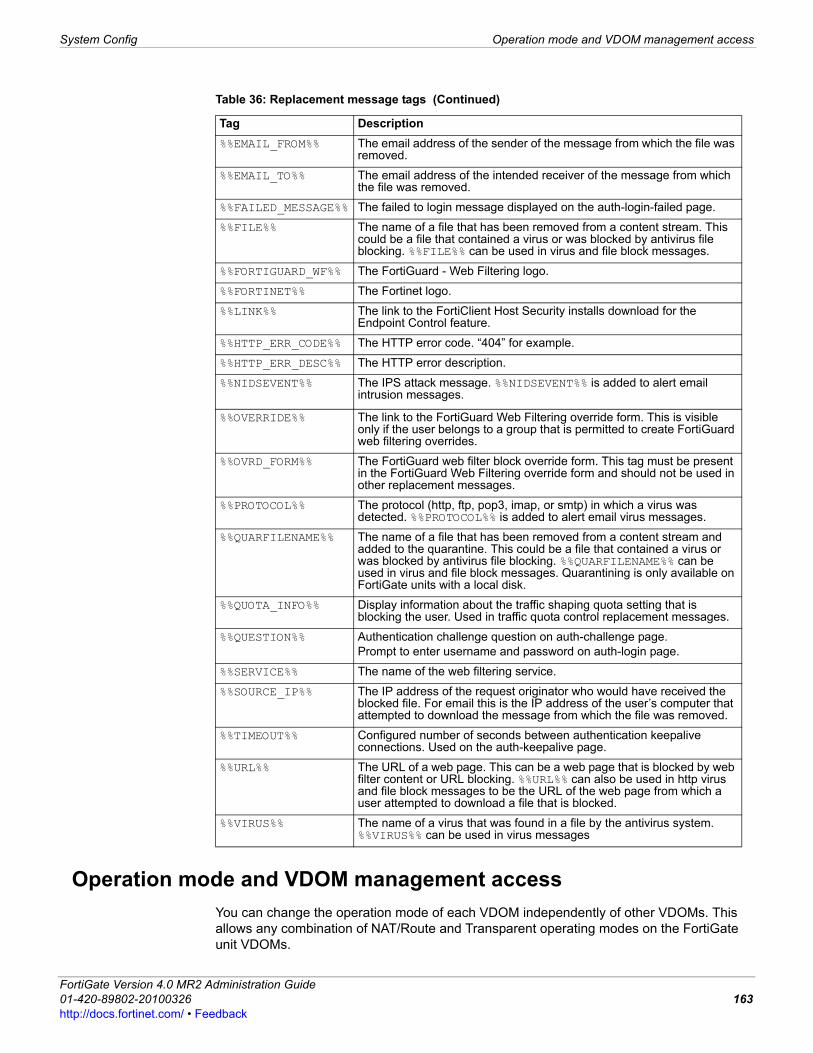
System Config Operation mode and VDOM management access
F0h
Operation mode and VDOM management accessYou can change the operation mode of each VDOM independently of other VDOMs. This allows any combination of NAT/Route and Transparent operating modes on the FortiGate unit VDOMs.
%%EMAIL_FROM%% The email address of the sender of the message from which the file was removed.
%%EMAIL_TO%% The email address of the intended receiver of the message from which the file was removed.
%%FAILED_MESSAGE%% The failed to login message displayed on the auth-login-failed page.
%%FILE%% The name of a file that has been removed from a content stream. This could be a file that contained a virus or was blocked by antivirus file blocking. %%FILE%% can be used in virus and file block messages.
%%FORTIGUARD_WF%% The FortiGuard - Web Filtering logo.
%%FORTINET%% The Fortinet logo.
%%LINK%% The link to the FortiClient Host Security installs download for the Endpoint Control feature.
%%HTTP_ERR_CODE%% The HTTP error code. “404” for example.
%%HTTP_ERR_DESC%% The HTTP error description.
%%NIDSEVENT%% The IPS attack message. %%NIDSEVENT%% is added to alert email intrusion messages.
%%OVERRIDE%% The link to the FortiGuard Web Filtering override form. This is visible only if the user belongs to a group that is permitted to create FortiGuard web filtering overrides.
%%OVRD_FORM%% The FortiGuard web filter block override form. This tag must be present in the FortiGuard Web Filtering override form and should not be used in other replacement messages.
%%PROTOCOL%% The protocol (http, ftp, pop3, imap, or smtp) in which a virus was detected. %%PROTOCOL%% is added to alert email virus messages.
%%QUARFILENAME%% The name of a file that has been removed from a content stream and added to the quarantine. This could be a file that contained a virus or was blocked by antivirus file blocking. %%QUARFILENAME%% can be used in virus and file block messages. Quarantining is only available on FortiGate units with a local disk.
%%QUOTA_INFO%% Display information about the traffic shaping quota setting that is blocking the user. Used in traffic quota control replacement messages.
%%QUESTION%% Authentication challenge question on auth-challenge page.Prompt to enter username and password on auth-login page.
%%SERVICE%% The name of the web filtering service.
%%SOURCE_IP%% The IP address of the request originator who would have received the blocked file. For email this is the IP address of the user’s computer that attempted to download the message from which the file was removed.
%%TIMEOUT%% Configured number of seconds between authentication keepalive connections. Used on the auth-keepalive page.
%%URL%% The URL of a web page. This can be a web page that is blocked by web filter content or URL blocking. %%URL%% can also be used in http virus and file block messages to be the URL of the web page from which a user attempted to download a file that is blocked.
%%VIRUS%% The name of a virus that was found in a file by the antivirus system. %%VIRUS%% can be used in virus messages
Table 36: Replacement message tags (Continued)
Tag Description
ortiGate Version 4.0 MR2 Administration Guide1-420-89802-20100326 163ttp://docs.fortinet.com/ • Feedback
Operation mode and VDOM management access System Config
Management access to a VDOM can be restricted based on which interfaces and protocols can be used to connect to the FortiGate unit.
Changing the operation modeYou can set the operating mode for your VDOM and perform sufficient network configuration to ensure that you can connect to the web-based manager in the new mode.There are two operation modes for the FortiGate unit - NAT/Route and Transparent. Each mode is well suited to different situations.
To switch from NAT/Route to Transparent mode1 Go to System > Config > Operation or select Change beside Operation Mode on the
System Status page for the virtual domain.2 From the Operation Mode list, select Transparent.3 Enter the following information and select Apply.
To switch from Transparent to NAT/Route mode1 Go to System > Config > Operation or select Change beside Operation Mode on the
System Status page for the virtual domain.2 From the Operation Mode list, select NAT.3 Enter the following information and select Apply.
Management accessManagement access defines how administrators are able to log on to the FortiGate unit to perform management tasks such as configuration and maintenance. Methods of access can include local access through the console connection, or remote access over a network or modem interface using various protocols including Telnet and HTTPS.You can configure management access on any interface in your VDOM. See “Configuring administrative access to an interface” on page 101. In NAT/Route mode, the interface IP address is used for management access. In Transparent mode, you configure a single management IP address that applies to all interfaces in your VDOM that permit management access. The FortiGate also uses this IP address to connect to the FDN for virus and attack updates (see “Configuring the FortiGate unit for FDN and FortiGuard subscription services” on page 203).
Management IP/Netmask Enter the management IP address and netmask. This must be a valid IP address for the network from which you want to manage the FortiGate unit.
Default Gateway Enter the default gateway required to reach other networks from the FortiGate unit.
Interface IP/Netmask Enter a valid IP address and netmask for the network from which you want to manage the FortiGate unit.
Device Select the interface to which the Interface IP/Netmask settings apply.
Default Gateway Enter the default gateway required to reach other networks from the FortiGate unit.
Gateway Device Select the interface to which the default gateway is connected.
FortiGate Version 4.0 MR2 Administration Guide164 01-420-89802-20100326
http://docs.fortinet.com/ • Feedback
System Config Operation mode and VDOM management access
F0h
The system administrator (admin) can access all VDOMs, and create regular administrator accounts. A regular administrator account can access only the VDOM to which it belongs. The management computer must connect to an interface in that VDOM. It does not matter to which VDOM the interface belongs. In both cases, the management computer must connect to an interface that permits management access and its IP address must be on the same network. Management access can be via HTTP, HTTPS, telnet, or SSH sessions if those services are enabled on the interface. HTTPS and SSH are preferred as they are more secure.You can allow remote administration of the FortiGate unit. However, allowing remote administration from the Internet could compromise the security of the FortiGate unit. You should avoid this unless it is required for your configuration. To improve the security of a FortiGate unit that allows remote administration from the Internet:• Use secure administrative user passwords.• Change these passwords regularly.• Enable secure administrative access to this interface using only HTTPS or SSH.• Use Trusted Hosts to limit where the remote access can originate from.• Do not change the system idle timeout from the default value of 5 minutes (see
“Settings” on page 183).
ortiGate Version 4.0 MR2 Administration Guide1-420-89802-20100326 165ttp://docs.fortinet.com/ • Feedback

Operation mode and VDOM management access System Config
FortiGate Version 4.0 MR2 Administration Guide166 01-420-89802-20100326
http://docs.fortinet.com/ • Feedback
System Admin Administrators
F0h
System AdminThis section describes how to configure administrator accounts on your FortiGate unit. Administrators access the FortiGate unit to configure its operation. The factory default configuration has one administrator, admin. After connecting to the web-based manager or the CLI, you can configure additional administrators with various levels of access to different parts of the FortiGate unit configuration.If you enable virtual domains (VDOMs) on the FortiGate unit, system administrators are configured globally for the entire FortiGate unit. For more information, see “Using virtual domains” on page 73.The following topics are included in this section:• Administrators• Admin profiles• Central Management• Settings• Monitoring administratorsFortiGate IPv6 support
AdministratorsThere are two levels of administrator accounts:
Users assigned to the super_admin profile:• cannot delete logged-in users who are also assigned the super_admin profile
Note: Always end your FortiGate session by logging out, in the CLI or the web-based manager. If you do not, the session remains open.
Regular administrators
An administrator with any admin profile other than super_admin. A regular administrator account has access to configuration options as determined by its Admin Profile. If virtual domains are enabled, the regular administrator is assigned to one VDOM and cannot access global configuration options or the configuration for any other VDOM. For information about which options are global and which are per VDOM, see “VDOM configuration settings” on page 74 and “Global configuration settings” on page 76.
System administrators
Includes the factory default system administrator admin, any other administrators assigned to the super_admin profile, and any administrator that is assigned to the super_admin_readonly profile. Any administrator assigned to the super_admin admin profile, including the default administrator account admin, has full access to the FortiGate unit configuration and general system settings that includes the ability to:• enable VDOM configuration• create VDOMs• configure VDOMs• assign regular administrators to VDOMs• configure global options• customize the FortiGate web-based manager.The super_admin admin profile cannot be changed; it does not appear in the list of profiles in System > Admin > Admin Profile, but it is one of the selections in the Admin Profile drop-down list in System > Admin New/Edit Administrator dialog box.
ortiGate Version 4.0 MR2 Administration Guide1-420-89802-20100326 167ttp://docs.fortinet.com/ • Feedback
Administrators System Admin
• can delete other users assigned the super_admin profile and/or change the configured authentication method, password, or admin profile, only if the other users are not logged in
• can delete the default “admin” account only if the default admin user is not logged in.By default, admin has no password. The password should be 32 characters or less. The password of users with the super_admin admin profile can be reset in the CLI. If the password of a user who is logged in is changed, the user will be logged out and prompted to re-authenticate with the new password.Example: For the user ITAdmin with the admin profile super_admin, to set that user’s password to 123456:config sys adminedit ITAdmin
set password 123456endExample: For the user ITAdmin with the admin profile super_admin, to reset the password from 123456 to the default ‘empty’:config sys admin
edit ITAdminunset password 123456
end
There is also an admin profile that allows read-only super admin privileges called super_admin_readonly. This profile cannot be deleted or changed, similar to the super_admin profile. The read-only super_admin profile is suitable in a situation where it is necessary for a system administrator to troubleshoot a customer configuration without being able to make changes. Other than being read-only, the super_admin_readonly profile can view all the FortiGate configuration tools.You can authenticate an administrator by using a password stored on the FortiGate unit, a remote authentication server (such as LDAP, RADIUS, or TACACS+), or by using PKI certificate-based authentication. To authenticate an administrator with an LDAP or TACACS+ server, you must add the server to an authentication list, include the server in a user group, and associate the administrator with the user group. The RADIUS server authenticates users and authorizes access to internal network resources based on the admin profile of the user. Users authenticated with the PKI-based certificate are permitted access to internal network resources based on the user group they belong to and the associated admin profile.A VDOM/admin profile override feature supports authentication of administrators via RADIUS. The admin user will have access depending on which VDOM and associated admin profile he or she is restricted to. This feature is available only to wildcard administrators, and can be set only through the FortiGate CLI. There can only be one VDOM override user per system. For more information, see the FortiGate CLI Reference.This topic contains the following: • Viewing the administrators list• Configuring an administrator account• Changing an administrator account password• Configuring regular (password) authentication for administrators• Configuring remote authentication for administrators• Configuring PKI certificate authentication for administrators
FortiGate Version 4.0 MR2 Administration Guide168 01-420-89802-20100326
http://docs.fortinet.com/ • Feedback
System Admin Administrators
F0h
Viewing the administrators listYou need to use the default ”admin” account, an account with the super_admin admin profile, or an administrator with read-write access control to add new administrator accounts and control their permission levels. If you log in with an administrator account that does not have the super_admin admin profile, the administrators list will show only the administrators for the current virtual domain.To view the list of administrators, go to System > Admin > Administrators.
Configuring an administrator accountYou need to use the default “admin” account, an account with the super_admin admin profile, or an administrator with read-write access control to create a new administrator.To create a new administrator, go to System > Admin > Administrators and select Create New.
Administrators pageLists the default super_admin administrator account and all administrator accounts that you created.
Create New Add an administrator account.
Name The login name for an administrator account.
Trusted Hosts The IP address and netmask of trusted hosts from which the administrator can log in. For more information, see “Using trusted hosts” on page 177.
Profile The admin profile for the administrator.
Type The type of authentication for this administrator, one of:
Local Authentication of an account with a local password stored on the FortiGate unit.
Remote Authentication of a specific account on a RADIUS, LDAP, or TACACS+ server.
Remote+Wildcard
Authentication of any account on an LDAP, RADIUS, or TACACS+ server.
PKI PKI-based certificate authentication of an account.
Delete Delete the administrator account.You cannot delete the original “admin” account until you create another user with the super_admin profile, log out of the “admin” account, and log in with the alternate user that has the super_admin profile.
Edit Edit or view the administrator account.
Change Password
Change the password for the administrator account. See “Changing an administrator account password” on page 170.
New Administrator page Provides settings for configuring an administrator account.
Administrator Enter the login name for the administrator account. The name of the administrator should not contain the characters <>()#"'. Using these characters in the administrator account name can result in a cross site scripting (XSS) vulnerability.
Type Select the type of administrator account:
Regular Select to create a Local administrator account. For more information, see “Configuring regular (password) authentication for administrators” on page 170.
ortiGate Version 4.0 MR2 Administration Guide1-420-89802-20100326 169ttp://docs.fortinet.com/ • Feedback
Administrators System Admin
Changing an administrator account passwordTo change an administrator password, go to System > Admin > Administrators, and select the Change Password icon next to the administrator account you want to change the password for. Enter and confirm the new password, and select OK to save the changes.
Configuring regular (password) authentication for administratorsYou can use a password stored on the local FortiGate unit to authenticate an administrator.
To configure an administrator to authenticate with a password stored on the FortiGate unit1 Go to System > Admin > Administrators.2 Select Create New, or select the Edit icon beside an existing administrator.3 Enter the following information:
Remote Select to authenticate the administrator using a RADIUS, LDAP, or TACACS+ server. Server authentication for administrators must be configured first. For more information, see “Configuring remote authentication for administrators” on page 171.
PKI Select to enable certificate-based authentication for the administrator. Only one administrator can be logged in with PKI authentication enabled. For more information, see “Configuring PKI certificate authentication for administrators” on page 176.
User Group Select the administrator user group that includes the Remote server/PKI (peer) users as members of the User Group. The administrator user group cannot be deleted once the group is selected for authentication.This is available only if Type is Remote or PKI.
Wildcard Select to allow all accounts on the RADIUS, LDAP, or TACACS+ server to be administrators.This is available only if Type is Remote. Only one wildcard user is permitted per VDOM.
Password Enter a password for the administrator account. For improved security, the password should be at least 6 characters long.This is not available if Wildcard is selected or when Type is PKI.For more information see the Fortinet Knowledge Base article Recovering lost administrator account passwords if you forget or lose an administrator account password and cannot log in to your FortiGate unit.
Confirm Password Type the password for the administrator account a second time to confirm that you have typed it correctly.This is not available if Wildcard is selected or when PKI authentication is selected.
Trusted Host #1Trusted Host #2Trusted Host #3
Enter the trusted host IP address and netmask this administrator login is restricted to on the FortiGate unit. You can specify up to three trusted hosts. These addresses all default to 0.0.0.0/0 or 0.0.0.0/0.0.0.0.For more information, see “Using trusted hosts” on page 177.
IPv6 Trusted Host #1IPv6 Trusted Host #2IPv6 Trusted Host #3
Enter the trusted host IPv6 address and netmask this administrator login is restricted to on the FortiGate unit. You can specify up to three trusted hosts. These addresses all default to ::/0.For more information, see “Using trusted hosts” on page 177.
Admin Profile Select the admin profile for the administrator. You can also select Create New to create a new admin profile. For more information on admin profiles, see “Configuring an admin profile” on page 181.
Administrator A name for the administrator.
Type Regular.
FortiGate Version 4.0 MR2 Administration Guide170 01-420-89802-20100326
http://docs.fortinet.com/ • Feedback
System Admin Administrators
F0h
4 Configure additional features as required. For more information, see “Configuring an administrator account” on page 169.
5 Select OK.When you select Regular for Type, you will see Local as the entry in the Type column when you view the list of administrators. For more information, see “Viewing the administrators list” on page 169.
Configuring remote authentication for administratorsYou can authenticate administrators using RADIUS, LDAP, or TACACS+ servers. In order to do this, you must configure the server, include the server as a user in a user group, and create the administrator account to include in the user group.
Configuring RADIUS authentication for administratorsRemote Authentication and Dial-in User Service (RADIUS) servers provide authentication, authorization, and accounting functions. FortiGate units use the authentication and authorization functions of the RADIUS server. To use the RADIUS server for authentication, you must configure the server before you configure the FortiGate users or user groups that will need it.
If you have configured RADIUS support and a user is required to authenticate using a RADIUS server, the FortiGate unit sends the user’s credentials to the RADIUS server for authentication. If the RADIUS server can authenticate the user, the user is successfully authenticated with the FortiGate unit. If the RADIUS server cannot authenticate the user, the FortiGate unit refuses the connection.If you want to use a RADIUS server to authenticate administrators in your VDOM, you must configure the authentication before you create the administrator accounts. To do this you need :• To configure the FortiGate unit to access the RADIUS server• To create the user group (RADIUS)• To configure an administrator to authenticate with a RADIUS serverThe following instructions assume there is a RADIUS server on your network populated with the names and passwords of your administrators. For information on how to set up a RADIUS server, see the documentation for your RADIUS server.To view the RADIUS server list, go to User > Remote > RADIUS.
Password A password for the administrator to use to authenticate.
Confirm Password
The password entered in Password.
Admin Profile The admin profile to apply to the administrator.
Note: If you forget or lose an administrator account password and cannot log in to your FortiGate unit, see the Fortinet Knowledge Base article Recovering a lost FortiGate administrator account passwords.
RADIUS pageLists all RADIUS servers that you configured. On this page, you can edit, delete and create a new RADIUS server.
Create New Add a new RADIUS server.
Name The name that identifies the RADIUS server on the FortiGate unit.
Server Name/IP The domain name or IP address of the RADIUS server.
ortiGate Version 4.0 MR2 Administration Guide1-420-89802-20100326 171ttp://docs.fortinet.com/ • Feedback
Administrators System Admin
To configure the FortiGate unit to access the RADIUS server1 Go to User > Remote > RADIUS.2 Select Create New, or select the Edit icon beside an existing RADIUS server.3 Enter the following information:
4 Select OK.For further information about RADIUS authentication, see “Configuring a RADIUS server” on page 452.
To create the user group (RADIUS)1 Go to User > User Group > User Group.2 Select Create New or select the Edit icon beside an existing RADIUS group.3 Enter the name that identifies the user group.4 For Type, enter Firewall.5 In the Available Users/Groups list, select the RADIUS server name and move it to the
Members list.6 Select OK.
To configure an administrator to authenticate with a RADIUS server1 Go to System > Admin > Administrators.2 Select Create New, or select the Edit icon beside an existing administrator.
Delete Delete a RADIUS server configuration.You cannot delete a RADIUS server that has been added to a user group.
Edit Edit a RADIUS server configuration.
Note: Access to the FortiGate unit depends on the VDOM associated with the administrator account.
Name A name that identifies the RADIUS server.
Primary Server Name/IP
Enter the domain name or IP address of the RADIUS server.
Primary Server Secret
Enter the RADIUS server secret. The RADIUS server administrator can provide this information.
Secondary Server Name/IP
Enter the domain name or IP address of a second RADIUS server (optional).
Secondary Server Secret
Enter the secondary RADIUS server secret (optional).
Authentication Scheme
Select one of Use Default Authentication Scheme or Specify Authentication Protocol. If you chose to specify the scheme, select one of the schemes from the drop-down menu.
NAS IP/Called Station ID
Enter the Network Attached Storage (NAS) IP address.
Include in every User Group
Select to add this RADIUS server to every user group in this VDOM (optional).
FortiGate Version 4.0 MR2 Administration Guide172 01-420-89802-20100326
http://docs.fortinet.com/ • Feedback
System Admin Administrators
F0h
3 Enter the following information:
4 Configure additional features as required. For more information, see “Configuring an administrator account” on page 169.
5 Select OK.For more information about using a RADIUS server to authenticate system administrators, see the Fortinet Knowledge Base article Using RADIUS for Admin Access and Authorization.
Configuring LDAP authentication for administratorsLightweight Directory Access Protocol (LDAP) is an Internet protocol used to maintain authentication data that may include departments, people, groups of people, passwords, email addresses, printers, etc.If you have configured LDAP support and an administrator is required to authenticate using an LDAP server, the FortiGate unit contacts the LDAP server for authentication. If the LDAP server cannot authenticate the administrator, the FortiGate unit refuses the connection.If you want to use an LDAP server to authenticate administrators in your VDOM, you must configure the authentication before you create the administrator accounts. To do this you need:• To configure an LDAP server• To create the user group (LDAP)• To configure an administrator to authenticate with an LDAP serverTo view the LDAP server list, go to User > Remote > LDAP.
To configure an LDAP server1 Go to User > Remote > LDAP.
Name A name that identifies the administrator.
Type Remote.
User Group The user group that includes the RADIUS server as a member.
Password The password the administrator uses to authenticate.
Confirm Password
The re-entered password that confirms the original entry in Password.
Admin Profile The admin profile to apply to the administrator.
LDAP page Lists all LDAP servers that you created. On this page, you can edit, delete or create a new LDAP page.
Create New Add a new LDAP server.
Name The name that identifies the LDAP server on the FortiGate unit.
Server Name/IP The domain name or IP address of the LDAP server.
Port The TCP port used to communicate with the LDAP server.
Common Name Identifier The common name identifier for the LDAP server.
Distinguished Name The distinguished name used to look up entries on the LDAP server.
Delete Delete the LDAP server configuration.
Edit Edit the LDAP server configuration.
ortiGate Version 4.0 MR2 Administration Guide1-420-89802-20100326 173ttp://docs.fortinet.com/ • Feedback
Administrators System Admin
2 Select Create New or select the Edit icon beside an existing LDAP server.3 Enter or select the following and select OK.
For further information about LDAP authentication, see “Configuring an LDAP server” on page 454.
To create the user group (LDAP)1 Go to User > User Group > User Group.2 Select Create New or select the Edit icon beside an existing user group.3 Enter a Name that identifies the LDAP user group.4 For Type, enter Firewall.5 In the Available Users/Groups list, select the LDAP server name and move it to the
Members list. 6 Select OK.
To configure an administrator to authenticate with an LDAP server1 Go to System > Admin > Administrators.2 Select Create New or select the Edit icon beside an existing administrator account.3 Enter or select the following:
Name The name that identifies the LDAP server on the FortiGate unit.
Server Name/IP The domain name or IP address of the LDAP server.
Server Port The TCP port used to communicate with the LDAP server.
Common Name Identifier
The common name identifier for the LDAP server.
Distinguished Name The base distinguished name for the server in the correct X.500 or LDAP format.
Query View the LDAP server Distinguished Name Query tree for the LDAP server that you are configuring so that you can cross-reference to the Distinguished Name.For more information, see “Using Query” on page 455.
Bind Type The type of binding for LDAP authentication.
Anonymous Bind using anonymous user search.
Regular Bind using a user name/password and then search.
Simple Bind using a simple password authentication without a search.
Filter Filter used for group searching. Available only if Bind Type is Anonymous or Regular.
User DN Distinguished name of user to be authenticated. Available only if Bind Type is Regular.
Password Password of user to be authenticated. Available only if Bind Type is Regular.
Secure Connection A check box that enables a secure LDAP server connection for authentication.
Protocol The secure LDAP protocol to use for authentication. Available only if Secure Connection is selected.
Certificate The certificate to use for authentication. Available only if Secure Connection is selected.
Administrator A name that identifies the administrator.
Type Remote.
FortiGate Version 4.0 MR2 Administration Guide174 01-420-89802-20100326
http://docs.fortinet.com/ • Feedback
System Admin Administrators
F0h
4 Configure additional features as required. For more information, see “Configuring an administrator account” on page 169.
Select OK.Configuring TACACS+ authentication for administratorsTerminal Access Controller Access-Control System (TACACS+) is a remote authentication protocol that provides access control for routers, network access servers, and other networked computing devices via one or more centralized servers.If you have configured TACACS+ support and an administrator is required to authenticate using a TACACS+ server, the FortiGate unit contacts the TACACS+ server for authentication. If the TACACS+ server cannot authenticate the administrator, the connection is refused by the FortiGate unit.If you want to use an TACACS+ server to authenticate administrators in your VDOM, you must configure the authentication before you create the administrator accounts. To do this you need:• To configure the FortiGate unit to access the TACACS+ server• To create the user group (TACACS+)• To configure an administrator to authenticate with a TACACS+ serverTo view the TACACS+ server list, go to User > Remote > TACACS+.
To configure the FortiGate unit to access the TACACS+ server1 Go to User > Remote > TACACS+.2 Select Create New, or select the Edit icon beside an existing TACACS+ server.3 Enter or select the following:
4 Select OK.
User Group The user group that includes the LDAP server as a member.
Wildcard A check box that allows all accounts on the LDAP server to be administrators.
Password The password the administrator uses to authenticate. Not available if Wildcard is enabled.
Confirm Password
The re-entered password that confirms the original entry in Password. Not available if Wildcard is enabled.
Admin Profile The admin profile to apply to the administrator.
TACACS+ pageLists all TACACS+ servers that you created. On this page, you can edit, delete or create a new TACACS+ server.
Create New Add a new TACACS+ server.
Server The server domain name or IP address of the TACACS+ server.
Authentication Type The supported authentication method. TACACS+ authentication methods include: Auto, ASCII, PAP, CHAP, and MSCHAP.
Delete Delete this TACACS+ server
Edit Edit this TACACS+ server.
Name Enter a name that identifies the TACACS+ server.
Server Name/IP Enter the server domain name or IP address of the TACACS+ server.
Server Key Enter the key to access the TACACS+ server. The maximum number is 16.
Authentication Type
Enter one of Auto, ASCII, PAP, CHAP, and MSCHAP. Auto authenticates using PAP, MSCHAP, and CHAP (in that order).
ortiGate Version 4.0 MR2 Administration Guide1-420-89802-20100326 175ttp://docs.fortinet.com/ • Feedback
Administrators System Admin
For further information about TACACS+ authentication, see “Configuring TACACS+ servers” on page 456.
To create the user group (TACACS+)1 Go to User > User Group.2 Select Create New, or select the Edit icon beside an existing user group.3 Enter a Name that identifies the TACAS+ user group.4 For Type, select Firewall.5 In the Available Users/Groups list, select the TACACS+ server name and move it to the
Members list.6 Select OK.
To configure an administrator to authenticate with a TACACS+ server1 Go to System > Admin > Administrators.2 Select Create New, or select the Edit icon beside an existing administrator.3 Enter or select the following:
4 Configure additional features as required. For more information, see “Configuring an administrator account” on page 169.
5 Select OK.
Configuring PKI certificate authentication for administratorsPublic Key Infrastructure (PKI) authentication uses a certificate authentication library that takes a list of peers, peer groups, and user groups and returns authentication successful or denied notifications. Users only need a valid certificate for successful authentication; no username or password is necessary.To use PKI authentication for an administrator, you must configure the authentication before you create the administrator accounts. To do this you need:• To configure a PKI user• To create the user group (PKI)• To configure an administrator to authenticate with a PKI certificateTo view the PKI user list, go to User > PKI > PKI.
Administrator A name that identifies the administrator.
Type Remote.
User Group The user group that includes the TACACS+ server as a member.
Wildcard Select to allow all accounts on the TACACS+ server to be administrators.
Password The password the administrator uses to authenticate. Not available if Wildcard is enabled.
Confirm Password
The re-entered password that confirms the original entry in Password. Not available if Wildcard is enabled.
Admin Profile The admin profile to apply to the administrator.
PKI pageLists all PKI user lists that you created. On this page you can edit, delete or create a new PKI user list.
Create New Add a new PKI user.
Name The name of the PKI user.
FortiGate Version 4.0 MR2 Administration Guide176 01-420-89802-20100326
http://docs.fortinet.com/ • Feedback

System Admin Administrators
F0h
To configure a PKI user1 Go to User > PKI > PKI.2 Select Create New, or select the Edit icon beside an existing PKI user.3 Enter the Name of the PKI user.4 For Subject, enter the text string that appears in the subject field of the certificate of the
authenticating user.5 Select the CA certificate used to authenticate this user.6 Select OK.
To create the user group (PKI)1 Go to User > User Group > User Group.2 Select Create New, or select the Edit icon beside an existing user group.3 Enter or select the following:
4 Select OK.
To configure an administrator to authenticate with a PKI certificate1 Go to System > Admin > Administrators.2 Select Create New, or select the Edit icon beside an existing administrator.3 Enter or select the following:
4 Configure additional features as required. For more information, see “Configuring an administrator account” on page 169.
5 Select OK.
Using trusted hostsSetting trusted hosts for all of your administrators increases the security of your network by further restricting administrative access. In addition to knowing the password, an administrator must connect only through the subnet or subnets you specify. You can even restrict an administrator to a single IP address if you define only one trusted host IP address with a netmask of 255.255.255.255.
Subject The text string that appears in the subject field of the certificate of the authenticating user.
CA The CA certificate that is used to authenticate this user.
Delete Delete this PKI user.
Edit Edit this PKI user.
Name The name that identifies the PKI user group.
Type Firewall.
Available Users/Groups
Select the PKI user name and move it to the Members list.
Administrator A name that identifies the administrator.
Type PKI.
User Group The user group that includes the PKI user as a member.
Admin Profile The admin profile to apply to the administrator.
ortiGate Version 4.0 MR2 Administration Guide1-420-89802-20100326 177ttp://docs.fortinet.com/ • Feedback

Admin profiles System Admin
When you set trusted hosts for all administrators, the FortiGate unit does not respond to administrative access attempts from any other hosts. This provides the highest security. If you leave even one administrator unrestricted, the unit accepts administrative access attempts on any interface that has administrative access enabled, potentially exposing the unit to attempts to gain unauthorized access.The trusted hosts you define apply both to the web-based manager and to the CLI when accessed through Telnet or SSH. CLI access through the console connector is not affected.The trusted host addresses all default to 0.0.0.0/0.0.0.0 for IPv4, or ::/0 for IPv6. If you set one of the zero addresses to a non-zero address, the other zero addresses will be ignored. The only way to use a wildcard entry is to leave the trusted hosts at 0.0.0.0/0.0.0.0 or ::0. However, this configuration is less secure.
Admin profilesEach administrator account belongs to an admin profile. The admin profile separates FortiGate features into access control categories for which an administrator with read/write access can enable none (deny), read only, or read/write access.The following table lists the web-based manager pages to which each category provides access.
Table 37: Admin profile control of access to Web-based manager pages
Access control Affected web-based manager pagesAdmin Users System > Admin > Administrators
System > Admin > Admin Profile
Antivirus Configuration UTM > AntiVirus
Application Control UTM > Application Control
Auth Users User
Data Leak Prevention (DLP) UTM > Data Leak Prevention
Email Filter UTM > Email Filter
Firewall Configuration Firewall
FortiGuard Update System > Maintenance > FortiGuard
IM, P2P & VoIP Configuration IM, P2P & VoIP > StatisticsIM, P2P & VoIP > User > Current UsersIM, P2P & VoIP > User > User ListIM, P2P & VoIP > User > Config
IPS Configuration UTM > Intrusion Protection
Log&Report Log&Report
Maintenance System > Maintenance
Network Configuration System > Network > InterfaceSystem > Network > ZoneSystem > Network > Web Proxy System > DHCP
Router Configuration Router
Spamfilter Configuration UTM > AntiSpam
FortiGate Version 4.0 MR2 Administration Guide178 01-420-89802-20100326
http://docs.fortinet.com/ • Feedback
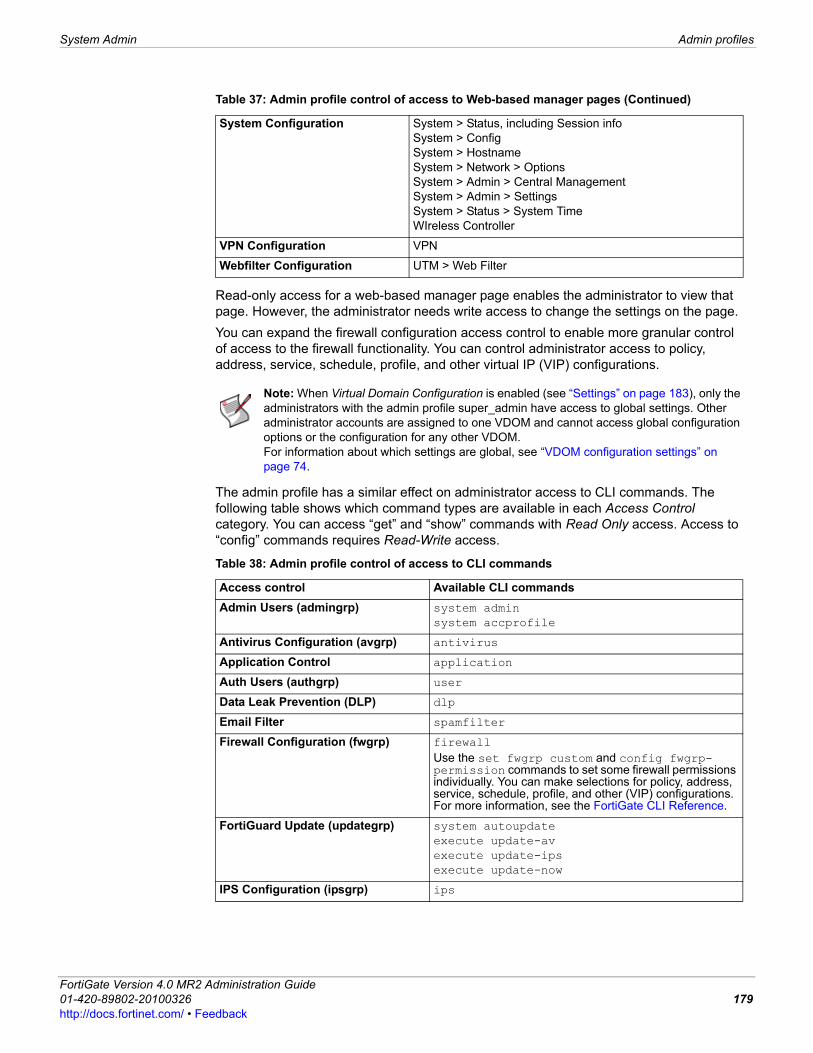
System Admin Admin profiles
F0h
Read-only access for a web-based manager page enables the administrator to view that page. However, the administrator needs write access to change the settings on the page.You can expand the firewall configuration access control to enable more granular control of access to the firewall functionality. You can control administrator access to policy, address, service, schedule, profile, and other virtual IP (VIP) configurations.
The admin profile has a similar effect on administrator access to CLI commands. The following table shows which command types are available in each Access Control category. You can access “get” and “show” commands with Read Only access. Access to “config” commands requires Read-Write access.
System Configuration System > Status, including Session infoSystem > ConfigSystem > HostnameSystem > Network > OptionsSystem > Admin > Central ManagementSystem > Admin > SettingsSystem > Status > System TimeWIreless Controller
VPN Configuration VPN
Webfilter Configuration UTM > Web Filter
Table 37: Admin profile control of access to Web-based manager pages (Continued)
Note: When Virtual Domain Configuration is enabled (see “Settings” on page 183), only the administrators with the admin profile super_admin have access to global settings. Other administrator accounts are assigned to one VDOM and cannot access global configuration options or the configuration for any other VDOM.For information about which settings are global, see “VDOM configuration settings” on page 74.
Table 38: Admin profile control of access to CLI commands
Access control Available CLI commandsAdmin Users (admingrp) system admin
system accprofile
Antivirus Configuration (avgrp) antivirus
Application Control application
Auth Users (authgrp) user
Data Leak Prevention (DLP) dlp
Email Filter spamfilter
Firewall Configuration (fwgrp) firewallUse the set fwgrp custom and config fwgrp-permission commands to set some firewall permissions individually. You can make selections for policy, address, service, schedule, profile, and other (VIP) configurations. For more information, see the FortiGate CLI Reference.
FortiGuard Update (updategrp) system autoupdateexecute update-avexecute update-ipsexecute update-now
IPS Configuration (ipsgrp) ips
ortiGate Version 4.0 MR2 Administration Guide1-420-89802-20100326 179ttp://docs.fortinet.com/ • Feedback
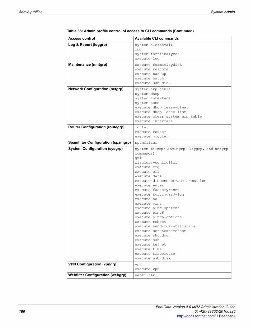
Admin profiles System Admin
Log & Report (loggrp) system alertemaillogsystem fortianalyzerexecute log
Maintenance (mntgrp) execute formatlogdiskexecute restoreexecute backupexecute batchexecute usb-disk
Network Configuration (netgrp) system arp-tablesystem dhcpsystem interfacesystem zoneexecute dhcp lease-clearexecute dhcp lease-listexecute clear system arp tableexecute interface
Router Configuration (routegrp) routerexecute routerexecute mrouter
Spamfilter Configuration (spamgrp) spamfilter
System Configuration (sysgrp) system (except admingrp, loggrp, and netgrp commands).guiwireless-controller execute cfgexecute cliexecute dateexecute disconnect-admin-sessionexecute enter execute factoryresetexecute fortiguard-log execute haexecute pingexecute ping-optionsexecute ping6execute ping6-optionsexecute rebootexecute send-fds-statisticsexecute set-next-rebootexecute shutdownexecute sshexecute telnetexecute timeexecute tracerouteexecute usb-disk
VPN Configuration (vpngrp) vpnexecute vpn
Webfilter Configuration (webgrp) webfilter
Table 38: Admin profile control of access to CLI commands (Continued)
Access control Available CLI commands
FortiGate Version 4.0 MR2 Administration Guide180 01-420-89802-20100326
http://docs.fortinet.com/ • Feedback
System Admin Admin profiles
F0h
To add admin profiles for FortiGate administrators, go to System > Admin > Admin Profile. Each administrator account belongs to an admin profile. An administrator with read/write access can create admin profiles that deny access to, allow read-only, or allow both read and write-access to FortiGate features.When an administrator has read-only access to a feature, the administrator can access the web-based manager page for that feature but cannot make changes to the configuration. There are no Create or Apply buttons and lists display only the View ( ) icon instead of icons for Edit, Delete or other modification commands.
Viewing the admin profiles listYou need to use the admin account or an account with Admin Users read/write access to create or edit admin profiles. To view the admin profiles list, go to System > Admin > Admin Profile.
Configuring an admin profileYou need to use the admin account or an account with Admin Users read/write access to edit an admin profile.
To configure an admin profile1 Go to System > Admin > Admin Profile. 2 Select Create New or select the Edit icon beside an existing profile. 3 Enter or select the profile options you want, and then select OK.
Admin Profile pageLists all administration profiles that you created as well as the default admin profiles. On this page, you can edit, delete or create a new admin profile. You can edit an existing admin profile, either a default admin profile or one that you created.
Create New Add a new admin profile.
Profile Name The name of the admin profile.
Delete Select to delete the admin profile. You cannot delete an admin profile that has administrators assigned to it.
Edit Select to modify the admin profile. When you select Edit, you are automatically redirected to the Edit Admin Profile page.
New Admin Profile pageProvides settings for configuring an administration profile. When you are editing an existing admin profile, you are automatically redirected to the Edit Admin Profile page.
Profile Name Enter the name of the admin profile.
Access Control List of the items that can customize access control settings if configured.
None Deny access to all Access Control categories.
Read Only Enable Read access in all Access Control categories.
Read-Write Select to allow read/write access in all Access Control categories.
Access Control (categories)
Make specific control selections as required. For detailed information about the Access Control categories, see “Admin profiles” on page 178.
ortiGate Version 4.0 MR2 Administration Guide1-420-89802-20100326 181ttp://docs.fortinet.com/ • Feedback
Central Management System Admin
Central ManagementThe Central Management tab provides the option of remotely managing your FortiGate unit by either a FortiManager unit or the FortiGuard Analysis and Management Service. From System > Admin > Central Management, you can configure your FortiGate unit to back up or restore configuration settings automatically to the specified central management server. The central management server is the type of service you enable, either a FortiManager unit or the FortiGuard Analysis and Management Service. If you have a subscription for FortiGuard Analysis and Management Service, you can also remotely upgrade the firmware on the FortiGate unit. When configuring central management settings, you can also specify the source IP address of the self-originated traffic; however, it is available only in the CLI (set fmg-source-ip).
When you are configuring your FortiGate unit to connect to and communicate with a FortiManager unit, the following steps must be taken because of the two different deployment scenarios. • FortiGate is directly reachable from FortiManager:
• In the FortiManager GUI, add the FortiGate unit to the FortiManager database in the Device Manager module
• Change the FortiManager IP address• Change the FortiGate IP address
Central Management pageProvides the settings for configuring central management options, as well as enabling or disabling the service on the FortiGate unit.
Enable Central Management
Enables the Central Management feature on the FortiGate unit.
Type Select the type of central management for this FortiGate unit. You can select FortiManager or the FortiGuard Management Service.
FortiManager Select to use FortiManager as the central management service for the FortiGate unit. Enter the IP address or name of the FortiManager unit in the IP/Name field. If your organization is operating a FortiManager cluster, add the IP address or name of the primary FortiManager unit to the IP/Name field and add the IP address or name of the backup FortiManager units to the Trusted FortiManager list.Status indicates whether or not the FortiGate unit can communicate with the FortiManager unit added to the IP/Name field.Select Register to include the FortiManager unit in the Trusted FortiManager List. A red arrow-down indicates that there is no connection enabled.A green arrow-up indicates that there is a connection. A yellow caution symbol appears when your FortiGate unit is considered an unregistered device by the FortiManager unit.
FortiGuard Management Service
Select to use the FortiGuard Management Service as the central management service for the FortiGate unit. Enter the Account ID in the Account ID field. If you do not have an account ID, register for the FortiGuard Management Service on the FortiGuard Management Service website. Select Change to go directly to System > Maintenance > FortiGuard. Under Analysis & Management Service Options, enter the account ID in the Account ID field.
FortiGate Version 4.0 MR2 Administration Guide182 01-420-89802-20100326
http://docs.fortinet.com/ • Feedback
System Admin Settings
F0h
• FortiGate behind NAT• In System > Admin > Central Management, choose FortiManager• Add the FortiManager unit to the Trusted FortiManager List, if applicable• Change the FortiManager IP address• Change the FortiGate IP address• Contact the FortiManager administrator to verify the FortiGate unit displays in the
Device list in the Device Manager module
Configuration revisionThe Configuration Revision menu, located in System > Maintenance > Configuration Revision, displays a list of the backed up configuration files. Revision control requires either a configured central management server, or the local hard drive. The central management server can either be a FortiManager unit or the FortiGuard Analysis & Management Service. For more information, see “Configuration Revision” on page 198.
SettingsThe Settings tab includes the following features that you can configure:• ports for HTTP/HTTPS administrative access and SSL VPN login• password policy for administrators and IPsec pre-shared keys• the idle timeout setting• settings for the language of the web-based manager and the number of lines displayed
in generated reports• PIN protection for LCD and control buttons (LCD-equipped models only)• SCP capability for users logged in via SSH • Wireless controller capability• IPv6 support on the web based manager.To configure settings, go to System > Admin > Settings, enter or select the following and select OK.
Administrators Settings pageProvides settings for configuring different system options, such as enabling IPv6 on the web-based manager.
Web Administration PortsHTTP TCP port to be used for administrative HTTP access. The default is
80.
HTTPS TCP port to be used for administrative HTTPS access. The default is 443.
SSLVPN Login Port An alternative HTTPS port number for remote client web browsers to connect to the FortiGate unit. The default port number is 10443.
Telnet Port TCP port to be used for administrative telnet access. The default is 23.
SSH Port TCP port to be used for administrative SSH access. The default is 22.
Enable SSH v1 compatibility
Enable compatibility with SSH v1 in addition to v2. (Optional)
Password PolicyEnable Select to enable the password policy.
ortiGate Version 4.0 MR2 Administration Guide1-420-89802-20100326 183ttp://docs.fortinet.com/ • Feedback

Monitoring administrators System Admin
Monitoring administratorsTo see the number of logged-in administrators, go to System > Dashboard > Status. Under System Information, you will see Current Administrators. Select Details to view information about the administrators currently logged in to the FortiGate unit.
Minimum Length Set the minimum acceptable length for passwords.
Must contain Select any of the following special character types to require in a password. Each selected type must occur at least once in the password.Upper Case Letters — A, B, C, ... ZLower Case Letters — a, b, c, ... zNumerical digits — 0, 1, 2, 3, 4, 5, 6, 7 8, 9Non-alphanumeric Letters — punctuation marks, @,#, ... %
Apply Password Policy to
Select where to apply the password policy:Admin Password — Apply to administrator passwords. If any password does not conform to the policy, require that administrator to change the password at the next login.IPSEC Preshared Key — Apply to preshared keys for IPSec VPNs. The policy applies only to new preshared keys. You are not required to change existing preshared keys.
Admin Password Expires after n days
Require administrators to change password after a specified number of days. Specify 0 to remove required periodic password changes.
Timeout SettingsIdle Timeout The number of minutes an administrative connection must be idle
before the administrator has to log in again. The maximum is 480 minutes (8 hours). To improve security, keep the idle timeout at the default value of 5 minutes.
Display SettingsLanguage The language the web-based manager uses. Choose from English,
Simplified Chinese, Japanese, Korean, Spanish, Traditional Chinese or French.You should select the language that the operating system of the management computer uses.
Lines per Page Number of lines per page to display in table lists. The default is 50. Range is from 20 - 1000.
IPv6 Support on GUI Enable to configure IPv6 options from the GUI (Firewall policy, route, address and address group). Default allows configuration from CLI only. For more information on IPv6, see the sections that include IPv6 related fields, or see “FortiGate IPv6 support” on page 185.
LCD Panel (LCD-equipped models only)PIN Protection Select and enter a 6-digit PIN.
Administrators must enter the PIN to use the control buttons and LCD.
Enable SCP Enable users logged in through the SSH to be able to use Secure Copy (SCP) to copy the configuration file.
Enable Wireless Controller Enable the Wireless Controller feature. Then you can access the Wireless Controller menu in the web-based manager and the corresponding CLI commands. For more information, see “Wireless Controller” on page 479.
Note: If you make a change to the default port number for HTTP, HTTPS, Telnet, or SSH, ensure that the port number is unique.
FortiGate Version 4.0 MR2 Administration Guide184 01-420-89802-20100326
http://docs.fortinet.com/ • Feedback
System Admin FortiGate IPv6 support
F0h
FortiGate IPv6 supportIPv6 is version 6 of the Internet Protocol, part of the TCP/IP protocol suite. It can provide billions more unique IP addresses than the previous standard, IPv4. The internet is currently in transition from IPv4 to IPv6 addressing. IPv6 hosts and routers maintain interoperability with the existing IPv4 infrastructure in two ways:• implementing dual IP layers to support both IPv6 and IPv4• using IPv6 over IPv4 tunneling to encapsulate IPv6 packets within IPv4 headers.FortiGate units are dual IP layer IPv6/IPv4 nodes, and support IPv6 in both NAT/Route, and Transparent operation modes. They support IPv6 overIPv4 tunneling as well as IPv6 routing, firewall policies and IPSec VPN. You can assign both an IPv4 and an IPv6 address to any interface on a FortiGate unit—the interface functions as two interfaces, one for IPv4-addressed packets and another for IPv6-addressed packets.For more information, see the FortiGate IPv6 Support Technical Note.
Configuring IPv6 on FortiGate unitsMany parts of the FortiGate configuration supports IPv6 addressing. Before you can work with IPv6 on the web-based manager, you must enable IPv6 support.To enable IPv6 support, go to System > Admin > Settings, then under Display Settings, select IPv6 Support on GUI.After you enable IPv6 support in the web-based manager, you can:• configure IPv6 interfaces (see System Network)• configure IPv6 DNS services (see System Network)• configure IPv6 administrative access (see System Admin)• create IPv6 static routes (see Router Static)• monitor IPv6 routes (see Router Monitor)• create IPv6 firewall addresses (see Firewall Address)• create IPv6 firewall address groups (see Firewall Address)• create IPv6 firewall policies such as DoS (see Firewall Policy)
Current Administrators information page (System Information widget)Lists the administrators that are currently logged into the web-based manager and CLI. You can disconnect administrators from this page as well as refresh the information on the page.
Disconnect Select to disconnect the selected administrators. This is available only if your admin profile gives you System Configuration write permission.
Refresh Select to update the list.
Close Select to close the window.
Select an administrator session, then select Disconnect to log off this administrator. This is available only if your admin profile gives you System Configuration write access. You cannot log off the default “admin” user.
User Name The administrator account name.
Type The type of access: http, https, jsconsole, sshv2.
From If Type is jsconsole, the value in From is N/A.Otherwise, Type contains the administrator’s IP address.
Time The date and time the administrator logged on.
ortiGate Version 4.0 MR2 Administration Guide1-420-89802-20100326 185ttp://docs.fortinet.com/ • Feedback
FortiGate IPv6 support System Admin
• perform antivirus scanning on IPv6 traffic• perform website filtering on IPv6 traffic• create VPNs that use IPv6 addressing (see IPsec VPN)Once IPv6 support is enabled, you can configure the IPv6 options using the web-based manager or the CLI. Note that some IPv6 configuration is only available in the CLI.For more information on configuring IPv6 support using the CLI, see the FortiGate CLI Reference.
IP version 6 addressWhile 32-bits of addresses, or just under 5 billion addresses, seems like a lot, they have been used up quickly. Between servers and routers that provide the backbone communications of the Internet, to large companies and governments with thousands of computers large portions of the IP address space were either reserved or used up. In 1998, IP version 6 was designed mainly to provide more addresses but also improve slightly on IP version 4 (IPv4). IP version 6 (IPv6) is defined in RFC 2460.With four bytes of addresses there are a total just under 5 billion addresses. IPv6 addresses are 32 bytes long, and have no problems of ever running out. This very large address space also allows for more logical organization of addresses which in turn promotes more efficient network management and routing.
IPv6 Address notationThe IPv6 addressing standard is specified in detail in RFC 3513. The following is a quick overview.
IPv6 addresses are normally written as eight groups of 4 hexadecimal digits each. For example,
3f2e:6a8b:78a3:0d82:1725:6a2f:0370:6234
is a valid IPv6 address.
If a 4 digit group is 0000, it may be omitted. For example,
3f2e:6a8b:78a3:0000:1725:6a2f:0370:6234
is the same IPv6 address as
3f2e:6a8b:78a3::1725:6a2f:0370:6234
You can use the “::” notation to indicate multiple consecutive omitted zero groups. There must not be more than one use of “::” in an address, as this is ambiguous. Also, you can omit leading zeros in a group. Thus
19a4:0478:0000:0000:0000:0000:1a57:ac9e
19a4:0478:0000:0000:0000::1a57:ac9e
19a4:478:0:0:0:0:1a57:ac9e
19a4:478:0::0:1a57:ac9e
19a4:478::1a57:ac9e
are all valid and are the same address.
For IPv4-compatible or IPv4-mapped IPv6 addresses, you can enter the IPv4 portion using either hexadecimal or dotted decimal, but the FortiGate CLI always shows the IPv4 portion in dotted decimal format. For all other IPv6 addresses, the CLI accepts and displays only hexadecimal.
FortiGate Version 4.0 MR2 Administration Guide186 01-420-89802-20100326
http://docs.fortinet.com/ • Feedback
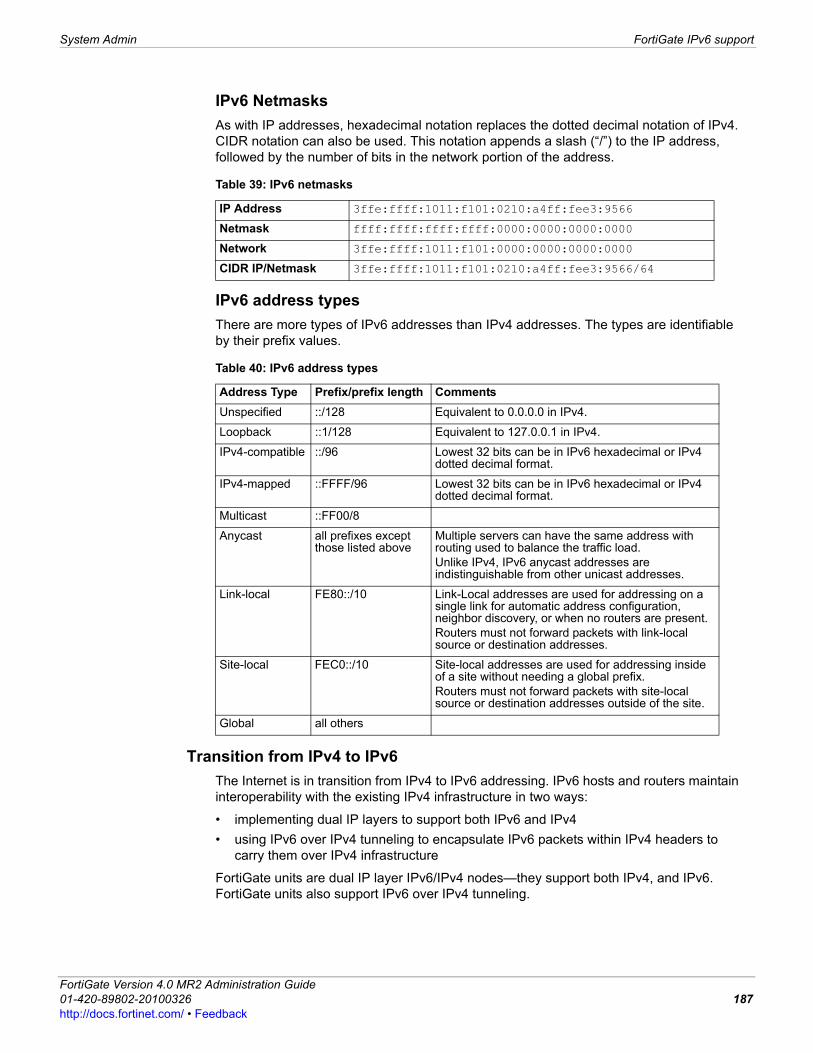
System Admin FortiGate IPv6 support
F0h
IPv6 NetmasksAs with IP addresses, hexadecimal notation replaces the dotted decimal notation of IPv4. CIDR notation can also be used. This notation appends a slash (“/”) to the IP address, followed by the number of bits in the network portion of the address.
IPv6 address typesThere are more types of IPv6 addresses than IPv4 addresses. The types are identifiable by their prefix values.
Transition from IPv4 to IPv6The Internet is in transition from IPv4 to IPv6 addressing. IPv6 hosts and routers maintain interoperability with the existing IPv4 infrastructure in two ways:
• implementing dual IP layers to support both IPv6 and IPv4• using IPv6 over IPv4 tunneling to encapsulate IPv6 packets within IPv4 headers to
carry them over IPv4 infrastructure
FortiGate units are dual IP layer IPv6/IPv4 nodes—they support both IPv4, and IPv6. FortiGate units also support IPv6 over IPv4 tunneling.
Table 39: IPv6 netmasks
IP Address 3ffe:ffff:1011:f101:0210:a4ff:fee3:9566
Netmask ffff:ffff:ffff:ffff:0000:0000:0000:0000
Network 3ffe:ffff:1011:f101:0000:0000:0000:0000
CIDR IP/Netmask 3ffe:ffff:1011:f101:0210:a4ff:fee3:9566/64
Table 40: IPv6 address types
Address Type Prefix/prefix length CommentsUnspecified ::/128 Equivalent to 0.0.0.0 in IPv4.
Loopback ::1/128 Equivalent to 127.0.0.1 in IPv4.
IPv4-compatible ::/96 Lowest 32 bits can be in IPv6 hexadecimal or IPv4 dotted decimal format.
IPv4-mapped ::FFFF/96 Lowest 32 bits can be in IPv6 hexadecimal or IPv4 dotted decimal format.
Multicast ::FF00/8
Anycast all prefixes except those listed above
Multiple servers can have the same address with routing used to balance the traffic load.Unlike IPv4, IPv6 anycast addresses are indistinguishable from other unicast addresses.
Link-local FE80::/10 Link-Local addresses are used for addressing on a single link for automatic address configuration, neighbor discovery, or when no routers are present.Routers must not forward packets with link-local source or destination addresses.
Site-local FEC0::/10 Site-local addresses are used for addressing inside of a site without needing a global prefix.Routers must not forward packets with site-local source or destination addresses outside of the site.
Global all others
ortiGate Version 4.0 MR2 Administration Guide1-420-89802-20100326 187ttp://docs.fortinet.com/ • Feedback
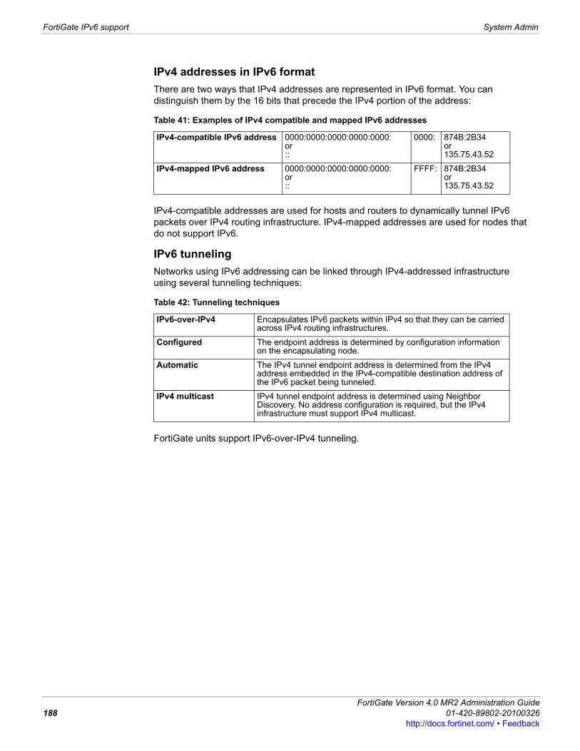
FortiGate IPv6 support System Admin
IPv4 addresses in IPv6 formatThere are two ways that IPv4 addresses are represented in IPv6 format. You can distinguish them by the 16 bits that precede the IPv4 portion of the address:
IPv4-compatible addresses are used for hosts and routers to dynamically tunnel IPv6 packets over IPv4 routing infrastructure. IPv4-mapped addresses are used for nodes that do not support IPv6.
IPv6 tunnelingNetworks using IPv6 addressing can be linked through IPv4-addressed infrastructure using several tunneling techniques:
FortiGate units support IPv6-over-IPv4 tunneling.
Table 41: Examples of IPv4 compatible and mapped IPv6 addresses
IPv4-compatible IPv6 address 0000:0000:0000:0000:0000: or::
0000: 874B:2B34 or135.75.43.52
IPv4-mapped IPv6 address 0000:0000:0000:0000:0000:or::
FFFF: 874B:2B34or135.75.43.52
Table 42: Tunneling techniques
IPv6-over-IPv4 Encapsulates IPv6 packets within IPv4 so that they can be carried across IPv4 routing infrastructures.
Configured The endpoint address is determined by configuration information on the encapsulating node.
Automatic The IPv4 tunnel endpoint address is determined from the IPv4 address embedded in the IPv4-compatible destination address of the IPv6 packet being tunneled.
IPv4 multicast IPv4 tunnel endpoint address is determined using Neighbor Discovery. No address configuration is required, but the IPv4 infrastructure must support IPv4 multicast.
FortiGate Version 4.0 MR2 Administration Guide188 01-420-89802-20100326
http://docs.fortinet.com/ • Feedback
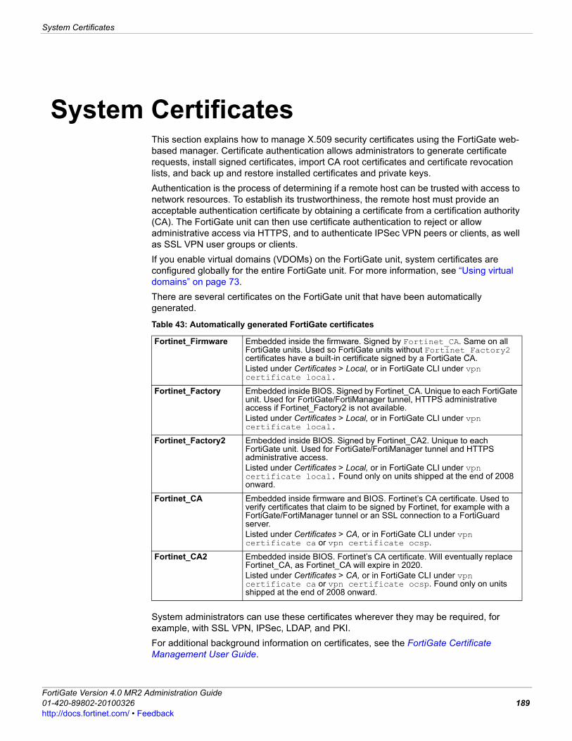
System Certificates
F0h
System CertificatesThis section explains how to manage X.509 security certificates using the FortiGate web-based manager. Certificate authentication allows administrators to generate certificate requests, install signed certificates, import CA root certificates and certificate revocation lists, and back up and restore installed certificates and private keys.Authentication is the process of determining if a remote host can be trusted with access to network resources. To establish its trustworthiness, the remote host must provide an acceptable authentication certificate by obtaining a certificate from a certification authority (CA). The FortiGate unit can then use certificate authentication to reject or allow administrative access via HTTPS, and to authenticate IPSec VPN peers or clients, as well as SSL VPN user groups or clients.If you enable virtual domains (VDOMs) on the FortiGate unit, system certificates are configured globally for the entire FortiGate unit. For more information, see “Using virtual domains” on page 73.There are several certificates on the FortiGate unit that have been automatically generated.
System administrators can use these certificates wherever they may be required, for example, with SSL VPN, IPSec, LDAP, and PKI.For additional background information on certificates, see the FortiGate Certificate Management User Guide.
Table 43: Automatically generated FortiGate certificates
Fortinet_Firmware Embedded inside the firmware. Signed by Fortinet_CA. Same on all FortiGate units. Used so FortiGate units without Fortinet_Factory2 certificates have a built-in certificate signed by a FortiGate CA.Listed under Certificates > Local, or in FortiGate CLI under vpn certificate local.
Fortinet_Factory Embedded inside BIOS. Signed by Fortinet_CA. Unique to each FortiGate unit. Used for FortiGate/FortiManager tunnel, HTTPS administrative access if Fortinet_Factory2 is not available.Listed under Certificates > Local, or in FortiGate CLI under vpn certificate local.
Fortinet_Factory2 Embedded inside BIOS. Signed by Fortinet_CA2. Unique to each FortiGate unit. Used for FortiGate/FortiManager tunnel and HTTPS administrative access.Listed under Certificates > Local, or in FortiGate CLI under vpn certificate local. Found only on units shipped at the end of 2008 onward.
Fortinet_CA Embedded inside firmware and BIOS. Fortinet’s CA certificate. Used to verify certificates that claim to be signed by Fortinet, for example with a FortiGate/FortiManager tunnel or an SSL connection to a FortiGuard server.Listed under Certificates > CA, or in FortiGate CLI under vpn certificate ca or vpn certificate ocsp.
Fortinet_CA2 Embedded inside BIOS. Fortinet’s CA certificate. Will eventually replace Fortinet_CA, as Fortinet_CA will expire in 2020.Listed under Certificates > CA, or in FortiGate CLI under vpn certificate ca or vpn certificate ocsp. Found only on units shipped at the end of 2008 onward.
ortiGate Version 4.0 MR2 Administration Guide1-420-89802-20100326 189ttp://docs.fortinet.com/ • Feedback
Local Certificates System Certificates
The following topics are included in this section:• Local Certificates• Remote Certificates• CA Certificates• CRL
Local Certificates Certificate requests and installed server certificates are displayed in the Local Certificates list. After you submit the request to a CA, the CA will verify the information and register the contact information on a digital certificate that contains a serial number, an expiration date, and the public key of the CA. The CA will then sign the certificate and send it to you to install on the FortiGate unit.Local certificates can update automatically online prior to expiry. This must be configured in the CLI. See the vpn certificate local command in the FortiGate CLI Reference.To view certificate requests and/or import signed server certificates, go to System > Certificates > Local Certificates. To view certificate details, select the View Certificate Detail icon in the row that corresponds to the certificate.
For detailed information and step-by-step procedures related to obtaining and installing digital certificates, see the FortiGate Certificate Management User Guide.
Note: SSL sessions that use client-certificates can now bypass the SSL inspection. For this to work properly, an SSL server should be set up that requires client-side certificates. These certificates are then uploaded to the client, making a connection through the FortiGate unit with the SSL inspection feature enabled on the FortiGate unit.
Local Certificates pageLists the default local certificates as well as the certificates that you have imported. You can also generate certificates from this page.
Generate Generate a local certificate request. For more information, see “Generating a certificate request” on page 191.
Import Import a signed local certificate. For more information, see “Importing a signed server certificate” on page 192.
Name The names of existing local certificates and pending certificate requests.
Subject The Distinguished Names (DNs) of local signed certificates.
Comments A description of the certificate.
Status The status of the local certificate. PENDING designates a certificate request that needs to be downloaded and signed.
View Certificate Detail
Display certificate details such as the certificate name, issuer, subject, and valid certificate dates.
Delete Delete the selected certificate request or installed server certificate from the FortiGate configuration. This is available only if the certificate has PENDING status.
Download Save a copy of the certificate request to a local computer. You can send the request to your CA to obtain a signed server certificate for the FortiGate unit (SCEP-based certificates only).
Edit Comments Select to edit the description of a certificate.
FortiGate Version 4.0 MR2 Administration Guide190 01-420-89802-20100326
http://docs.fortinet.com/ • Feedback
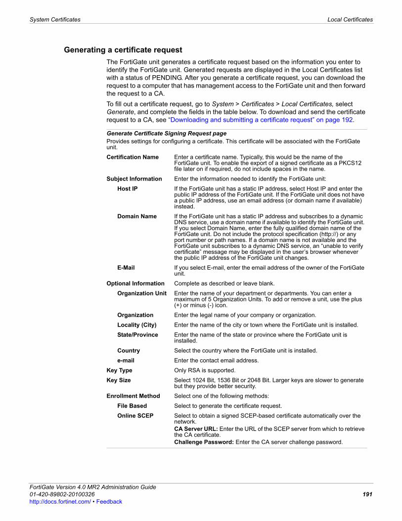
System Certificates Local Certificates
F0h
Generating a certificate requestThe FortiGate unit generates a certificate request based on the information you enter to identify the FortiGate unit. Generated requests are displayed in the Local Certificates list with a status of PENDING. After you generate a certificate request, you can download the request to a computer that has management access to the FortiGate unit and then forward the request to a CA.To fill out a certificate request, go to System > Certificates > Local Certificates, select Generate, and complete the fields in the table below. To download and send the certificate request to a CA, see “Downloading and submitting a certificate request” on page 192.
Generate Certificate Signing Request pageProvides settings for configuring a certificate. This certificate will be associated with the FortiGate unit.
Certification Name Enter a certificate name. Typically, this would be the name of the FortiGate unit. To enable the export of a signed certificate as a PKCS12 file later on if required, do not include spaces in the name.
Subject Information Enter the information needed to identify the FortiGate unit:
Host IP If the FortiGate unit has a static IP address, select Host IP and enter the public IP address of the FortiGate unit. If the FortiGate unit does not have a public IP address, use an email address (or domain name if available) instead.
Domain Name If the FortiGate unit has a static IP address and subscribes to a dynamic DNS service, use a domain name if available to identify the FortiGate unit. If you select Domain Name, enter the fully qualified domain name of the FortiGate unit. Do not include the protocol specification (http://) or any port number or path names. If a domain name is not available and the FortiGate unit subscribes to a dynamic DNS service, an “unable to verify certificate” message may be displayed in the user’s browser whenever the public IP address of the FortiGate unit changes.
E-Mail If you select E-mail, enter the email address of the owner of the FortiGate unit.
Optional Information Complete as described or leave blank.
Organization Unit Enter the name of your department or departments. You can enter a maximum of 5 Organization Units. To add or remove a unit, use the plus (+) or minus (-) icon.
Organization Enter the legal name of your company or organization.
Locality (City) Enter the name of the city or town where the FortiGate unit is installed.
State/Province Enter the name of the state or province where the FortiGate unit is installed.
Country Select the country where the FortiGate unit is installed.
e-mail Enter the contact email address.
Key Type Only RSA is supported.
Key Size Select 1024 Bit, 1536 Bit or 2048 Bit. Larger keys are slower to generate but they provide better security.
Enrollment Method Select one of the following methods:
File Based Select to generate the certificate request.
Online SCEP Select to obtain a signed SCEP-based certificate automatically over the network.CA Server URL: Enter the URL of the SCEP server from which to retrieve the CA certificate.Challenge Password: Enter the CA server challenge password.
ortiGate Version 4.0 MR2 Administration Guide1-420-89802-20100326 191ttp://docs.fortinet.com/ • Feedback
Local Certificates System Certificates
Downloading and submitting a certificate requestYou have to fill out a certificate request and generate the request before you can submit the results to a CA. For more information, see “Generating a certificate request” on page 191.
To download and submit a certificate request1 Go to System > Certificates > Local Certificates.2 In the Local Certificates list, select the Download icon in the row that corresponds to
the generated certificate request.3 In the File Download dialog box, select Save to Disk.4 Name the file and save it to the local file system.5 Submit the request to your CA as follows:
• Using the web browser on the management computer, browse to the CA web site.• Follow the CA instructions to place a base-64 encoded PKCS#12 certificate request
and upload your certificate request.• Follow the CA instructions to download their root certificate and Certificate
Revocation List (CRL), and then install the root certificate and CRL on each remote client (refer to the browser documentation).
6 When you receive the signed certificate from the CA, install the certificate on the FortiGate unit. See “Importing a signed server certificate” on page 192.
Importing a signed server certificateYour CA will provide you with a signed server certificate to install on the FortiGate unit. When you receive the signed certificate from the CA, save the certificate on a computer that has management access to the FortiGate unit. The certificate file can be in either PEM or DER format. To import the signed server certificate, go to System > Certificates > Local Certificates, select Import, enter the required information, and then select OK.
Importing an exported server certificate and private key. You will need to know the password in order to import the certificate file. Before you begin, save a copy of the file on a computer that has management access to the FortiGate unit. For more information, see the FortiGate Certificate Management User Guide.To import the PKC S12 file, go to System > Certificates > Local Certificates, select Import, enter the required information, and then select OK.
Import Certificate pageProvides settings for importing a specific signed certificate. The following settings are available when you select Local Certificate from the Type drop-down list.
Type Select Local Certificate.
Certificate File Enter the full path to and file name of the signed server certificate.
Browse Alternatively, browse to the location on the management computer where the certificate has been saved and select the certificate.
Import Certificate pageProvides settings for importing a specific signed certificate. The following settings are available when you select PKCS12 Certificate from the Type drop-down list.
Type Select PKCS12 Certificate.
FortiGate Version 4.0 MR2 Administration Guide192 01-420-89802-20100326
http://docs.fortinet.com/ • Feedback
System Certificates Remote Certificates
F0h
Importing separate server certificate and private key filesWhen the server certificate request and private key were not generated by the FortiGate unit, you will receive them as separate files. Copy the two files to the management computer.To import the certificate and private key files, go to System > Certificates > Local Certificates, select Import, enter the required information, and then select OK.
Remote CertificatesFor dynamic certificate revocation, you need to use an Online Certificate Status Protocol (OCSP) server. Remote certificates are public certificates without a private key. The OCSP is configured in the CLI only. For more information, see the FortiGate CLI Reference.Installed Remote (OCSP) certificates are displayed in the Remote Certificates list.To view installed Remote (OCSP) certificates or import a Remote (OCSP) certificate, go to System > Certificates > Remote. To view certificate details, select the View Certificate Detail icon in the row that corresponds to the certificate.
Certificate with key file Enter the full path to and file name of the previously exported PKCS12 file.
Browse Alternatively, browse to the location on the management computer where the PKCS12 file has been saved, select the file, and then select OK.
Password Type the password needed to upload the PKCS12 file.
Import Certificate pageProvides settings for importing a specific signed certificate from the CA. The following settings are available when you select Certificate from the Type drop-down list.
Type Select Certificate.
Certificate file Enter the full path to and file name of the previously exported certificate file.
Browse Alternatively, browse to the location of the previously exported certificate file, select the file, and then select OK.
Key file Enter the full path to and file name of the previously exported key file.
Browse Alternatively, browse to the location of the previously exported key file, select the file, and then select OK.
Password If a password is required to upload and open the files, type the password.
Note: The certificate file must not use 40-bit RC2-CBC encryption.
Note: There is one OCSP per VDOM.
Remote pageLists the public certificates. On this page you can import, delete and view certificates.
Import Import a public OCSP certificate. See “Importing CA certificates” on page 195.
Name The names of existing Remote (OCSP) certificates. The FortiGate unit assigns unique names (REMOTE_Cert_1, REMOTE_Cert_2, REMOTE_Cert_3, and so on) to the Remote (OCSP) certificates when they are imported.
ortiGate Version 4.0 MR2 Administration Guide1-420-89802-20100326 193ttp://docs.fortinet.com/ • Feedback

CA Certificates System Certificates
Importing Remote (OCSP) certificatesThe system assigns a unique name to each Remote (OCSP) certificate. The names are numbered consecutively (REMOTE_Cert_1, REMOTE_Cert_2, REMOTE_Cert_3, and so on).To import a Remote (OCSP) certificate, go to System > Certificates > Remote and select Import.
CA Certificates When you apply for a signed personal or group certificate to install on remote clients, you must obtain the corresponding root certificate and CRL from the issuing CA.When you receive the certificate, install it on the remote clients according to the browser documentation. Install the corresponding root certificate and CRL from the issuing CA on the FortiGate unit.CA certificates can update automatically online prior to expiry. This must be configured in the CLI. See the vpn certificate local command in the FortiGate CLI Reference.Installed CA certificates are displayed in the CA Certificates list. You cannot delete the Fortinet_CA certificate. To view installed CA root certificates or import a CA root certificate, go to System > Certificates > CA Certificates. To view root certificate details, select the View Certificate Detail icon in the row that corresponds to the certificate.For detailed information and step-by-step procedures related to obtaining and installing digital certificates, see the FortiGate Certificate Management User Guide.
Subject Information about the Remote (OCSP) certificate.
Delete Delete a Remote (OCSP) certificate from the FortiGate configuration.
View Certificate Detail
Display certificate details.
Download Save a copy of the Remote (OCSP) certificate to a local computer.
Upload Remote CertificateProvides settings for uploading a remote certificate to the FortiGate unit.
Local PC Enter the location in a management PC to upload a public certificate.
Browse Alternatively, browse to the location on the management computer where the certificate has been saved, select the certificate, and then select OK.
CA Certificates pageLists the CA certificates that you have created as well as the default CA certificate. You can also import a CA certificate.
Import Import a CA root certificate. See “Importing CA certificates” on page 195.
Name The names of existing CA root certificates. The FortiGate unit assigns unique names (CA_Cert_1, CA_Cert_2, CA_Cert_3, and so on) to the CA certificates when they are imported.
Subject Information about the issuing CA.
Delete Delete a CA root certificate from the FortiGate configuration.
View Certificate Detail
Display certificate details.
Download Save a copy of the CA root certificate to a local computer.
FortiGate Version 4.0 MR2 Administration Guide194 01-420-89802-20100326
http://docs.fortinet.com/ • Feedback
System Certificates CRL
F0h
Importing CA certificatesAfter you download the root certificate of the CA, save the certificate on a PC that has management access to the FortiGate unit.If you choose SCEP, the system starts the retrieval process as soon as you select OK.The system assigns a unique name to each CA certificate. The names are numbered consecutively (CA_Cert_1, CA_Cert_2, CA_Cert_3, and so on).To import a CA root certificate, go to System > Certificates > CA Certificates and select Import.
CRLA Certificate Revocation List (CRL) is a list of CA certificate subscribers paired with certificate status information. Installed CRLs are displayed in the CRL list. The FortiGate unit uses CRLs to ensure that the certificates belonging to CAs and remote clients are valid.To view installed CRLs, go to System > Certificates > CRL.
Importing a certificate revocation listCertificate revocation lists from CA web sites must be kept updated on a regular basis to ensure that clients having revoked certificates cannot establish a connection with the FortiGate unit. After you download a CRL from the CA web site, save the CRL on a computer that has management access to the FortiGate unit.The system assigns a unique name to each CRL. The names are numbered consecutively (CRL_1, CRL_2, CRL_3, and so on).To import a certificate revocation list, go to System > Certificates > CRL and select Import.
Import CA CertificateProvides settings for importing certificates using an SCEP server or Local PC.
SCEP Select to use an SCEP server to access CA certificate for user authentication. Enter the URL of the SCEP server from which to retrieve the CA certificate. Optionally, enter identifying information of the CA, such as the file name. Select OK.
Local PC Select to use a local administrator’s PC to upload a public certificate. Enter the location, or browse to the location on the management computer where the certificate has been saved, select the certificate, and then select OK.
CRL pageLists each individual CRL. On this page you can import, view or download CRLs.
Import Import a CRL. For more information, see “Importing a certificate revocation list” on page 195.
Name The names of existing certificate revocation lists. The FortiGate unit assigns unique names (CRL_1, CRL_2, CRL_3, and so on) to certificate revocation lists when they are imported.
Subject Information about the certificate revocation lists.
Delete Delete the selected CRL from the FortiGate configuration.
View Certificate Detail
Display CRL details such as the issuer name and CRL update dates.
Download Save a copy of the CRL to a local computer.
ortiGate Version 4.0 MR2 Administration Guide1-420-89802-20100326 195ttp://docs.fortinet.com/ • Feedback
CRL System Certificates
Import CRL pageProvides settings to import CRLs from a HTTP, LDAP, SCEP server, or local PC.
HTTP Select to use an HTTP server to retrieve the CRL. Enter the URL of the HTTP server.
LDAP Select to use an LDAP server to retrieve the CRL, then select the LDAP server from the list.
SCEP Select to use an SCEP server to retrieve the CRL, then select the Local Certificate from the list. Enter the URL of the SCEP server from which the CRL can be retrieved.
Local PC Select to use a local administrator’s PC to upload a public certificate. Enter the location, or browse to the location on the management computer where the certificate has been saved, select the certificate, and then select OK.
Note: When the CRL is configured with an LDAP, HTTP, and/or SCEP server, the latest version of the CRL is retrieved automatically from the server when the FortiGate unit does not have a copy of it or when the current copy expires.
FortiGate Version 4.0 MR2 Administration Guide196 01-420-89802-20100326
http://docs.fortinet.com/ • Feedback
System Maintenance Maintenance overview
F0h
System MaintenanceThis section describes how to maintain your system configuration as well as how to enable and update FDN services. This section also explains the types of FDN services that are available for your FortiGate unit. If you enable virtual domains (VDOMs) on the FortiGate unit, system maintenance is configured globally for the entire FortiGate unit. For more information, see “Using virtual domains” on page 73.The following topics are included in this section:• Maintenance overview• Configuration Revision• Firmware• FortiGuard• Troubleshooting FDN connectivity• Updating antivirus and attack definitions• Enabling push updates• Advanced• Adding VDOM Licenses• Disk
Maintenance overviewThe maintenance menu provides help with maintaining and managing firmware, configuration revisions, script files, and FortiGuard subscription-based services. From this menu, you can upgrade or downgrade the firmware, view historical backups of configuration files, or update FortiGuard services. The maintenance menu has the following menus: • Revision Control - displays all system configuration backups with the date and time of
when they were backed up. Before you can use revision control, a Central Management server must be configured and enabled.
• Firmware - displays the firmware images that are currently stored on the FortiGate unit as well as the firmware image currently running on the FortiGate unit.
• Advanced - displays advanced settings for scripts, USB auto-install and allows downloads of the debug log.
• FortiGuard - displays all FDN subscription services, such as antivirus and IPS definitions as well as the FortiGuard Analysis & Management Service. This tab also provides configuration options for antivirus, IPS, web filtering, and antispam services.
• License - allows you to increase the maximum number of VDOMs (on some FortiGate models).
• Disk - displays detailed information about the status of multiple local disks.
ortiGate Version 4.0 MR2 Administration Guide1-420-89802-20100326 197ttp://docs.fortinet.com/ • Feedback
Configuration Revision System Maintenance
When backing up the system configuration, web content files and email filtering files are also included. You can save the configuration to the management computer, a USB disk if your FortiGate unit includes a USB port (see “Formatting USB Disks” on page 200), or to its local hard disk. You can also restore the system configuration from previously downloaded backup files in the Backup & Restore menu.When virtual domain configuration is enabled, the content of the backup file depends on the administrator account that created it. A backup of the system configuration from the super_admin account contains global settings and the settings included in each VDOM. Only the super_admin can restore the configuration from this file. When you back up the system configuration from a regular administrator account, the backup file contains the global settings and the settings for the VDOM that the regular administrator belongs to. A regular administrator is the only user account that can restore the configuration from this file.Some FortiGate models support FortiClient by storing a FortiClient image that users can download. The FortiClient section of Backup & Restore is available if your FortiGate model supports FortiClient.
Configuration RevisionThe Configuration Revisions menu enables you to manage multiple versions of configuration files. Revision control requires either a configured central management server, or the local hard drive. The central management server can either be a FortiManager unit or the FortiGuard Analysis & Management Service. If central management is not configured on your FortiGate unit, a message appears to tell you to do one of the following:• enable central management (see “Central Management” on page 182)• obtain a valid license.When revision control is enabled on your FortiGate unit, and configurations have been backed up, a list of saved revisions of those backed-up configurations appears. To view the configuration revisions, go to System > Maintenance > Configuration Revision.
Tip: For simplified procedures on managing firmware, including backup and restore options as well as uploading and downloading firmware for your FortiGate unit, see “Firmware management practices” on page 61.
Configuration Revision pageLists all the configuration revisions. On this page, you can delete, edit or upload a configuration file. This page also allows you to change comments, view the differences between revisions, and revert to a previous configuration.
OS Version <firmware_version_build>(appears as sections on the page)
The section of the page that contains the configuration files that belong to the specified FortiOS firmware version and build number. For example, if you have four configuration revisions for 4.0 MR1 (build-178) they appear in the section OS Version 4.00 build178 on the Configuration Revision page.
Revision An incremental number indicating the order in which the configurations were saved. These may not be consecutive numbers if configurations are deleted.The most recent, and highest, number is first in the list.
Date/Time The date and time this configuration was saved on the FortiGate unit.
Administrator The administrator account that was used to back up this revision.
FortiGate Version 4.0 MR2 Administration Guide198 01-420-89802-20100326
http://docs.fortinet.com/ • Feedback
System Maintenance Firmware
F0h
Firmware The Firmware menu allows you to install firmware on your FortiGate unit, as well as upload a firmware image to install at a later date. You can also view what firmware is currently running on the FortiGate unit from this menu. To view firmware images, as well as upload and install an image, go to System > Maintenance > Firmware.
This topic contains the following: • Backing up and restoring configuration files• Formatting USB Disks• Remote FortiManager backup and restore options• Remote FortiGuard backup and restore options
Comments Any relevant information saved with the revision, such as why the revision was saved, who saved it, and if there is a date when it can be deleted to free up space.
Diff Select to compare two revisions.A window will appear, from which you can view and compare the selected revision to one of:• the current configuration• a selected revision from the displayed list including revision history
and templates• a specified revision number.
Download Download this revision to your local PC.
Revert Restore the previous selected revision. You will be prompted to confirm this action.
Delete Select to remove a configuration revision from the list.
Details Select to view the CLI settings of a configuration revision.
Change Comments Select to modify the description.
Upload Select to upload a configuration file to the FortiGate unit, which is then added to the list.
Firmware pageLists all firmware images that have been uploaded to the FortiGate unit.
Currently Running Firmware
Displays the firmware image that is currently running on the FortiGate unit.
Delete Select to remove the firmware image from the list.
Change Comments Select to change the description for the firmware image.
Upgrade You must select the firmware image in the list to install that image on the FortiGate unit.
Upload When you select Upload, you are automatically redirected to the Upload page. On this page you can select the firmware image to upload, enable Boot New Firmware (which installs the selected firmware on the FortiGate unit), and enter any description about the firmware that you want.
Firmware Version The firmware version number of the firmware image.
Date The date the firmware image was created on.
Create by The administrator who uploaded the firmware image.
Comments The description about the image.
ortiGate Version 4.0 MR2 Administration Guide1-420-89802-20100326 199ttp://docs.fortinet.com/ • Feedback
Firmware System Maintenance
Backing up and restoring configuration files You can backup or restore your FortiGate configuration to your management PC, a central management server, or a USB disk. You can back up and restore your configuration to a USB disk if the FortiGate unit includes a USB port and if you have connected a USB disk to the USB port. FortiGate units support most USB disks including USB keys and external USB hard disks (see “Formatting USB Disks” on page 200). The central management server is whatever remote management service the FortiGate unit is connected to. For example, if the current configuration on a FortiGate-60 is backed up to a FortiManager unit, the central management server is the FortiManager unit. You must configure central management in System > Admin > Central Management before these options are available in the Backup & Restore section. For more information, see “Central Management” on page 182.Backup and restore settings are available only in the CLI. The execute backup config command and execute restore config command are used to backup and restore the FortiGate unit’s configuration file.
Formatting USB Disks
FortiGate units with USB ports support USB disks for backing up and restoring configurations.FortiUSB and generic USB disks are supported, but the generic USB disk must be formatted as a FAT16 disk. No other partition type is supported.There are two ways that you can format the USB disk, either by using the CLI or a Windows system. You can format the USB disk in the CLI using the command syntax, exe usb-disk format. When using a Windows system to format the disk, at the command prompt type, “format <drive_letter>: /FS:FAT /V:<drive_label>” where <drive_letter> is the letter of the connected USB drive you want to format, and <drive_label> is the name you want to give the USB drive for identification.
Remote FortiManager backup and restore optionsYour FortiGate unit can be remotely managed by a FortiManager unit. The FortiGate unit connects using the FortiGuard-FortiManager protocol. This protocol provides communication between a FortiGate unit and a FortiManager unit, and runs over SSL using IPv4/TCP port 541. For detailed instructions on how to install a FortiManager unit, see the FortiManager Install Guide.After successfully connecting to the FortiManager unit from your FortiGate unit, you can back up your configuration to the FortiManager unit. You can also restore your configuration.The automatic configuration backup is available only in local mode on the FortiManager unit. A list of revisions is displayed when restoring the configuration from a remote location. The list allows you to choose the configuration to restore.
Caution: Formatting the USB disk deletes all information on the disk. Back up the information on the USB disk before formatting to ensure all information on the disk is recoverable.
FortiGate Version 4.0 MR2 Administration Guide200 01-420-89802-20100326
http://docs.fortinet.com/ • Feedback
System Maintenance FortiGuard
F0h
Remote FortiGuard backup and restore optionsYour FortiGate unit can be remotely managed by a central management server, which is available when you register for the FortiGuard Analysis & Management Service. The FortiGuard Analysis & Management Service is a subscription-based service and is purchased by contacting support. Additional information, including how to register you FortiGate unit for the FortiGuard Analysis & Management Service, is available in the FortiGuard Analysis & Management Service Users Guide. After registering, you can back up or restore your configuration. The FortiGuard Analysis & Management Service is useful when administering multiple FortiGate units without having a FortiManager unit. You can also upgrade the firmware on your FortiGate unit using the FortiGuard Analysis & Management Service. Upgrading the firmware is available in the Firmware Upgrade section of the backup and restore menu. For more information about upgrading firmware from the backup and restore menu, see “Changing the FortiGate firmware” on page 42.
When restoring the configuration from a remote location, a list of revisions is displayed so that you can choose the configuration file to restore.
FortiGuardGo to System > Maintenance > FortiGuard to configure your FortiGate unit to use the FortiGuard Distribution Network (FDN) and FortiGuard Services. The FDN provides updates to antivirus definitions, IPS definitions, and the Antispam rule set. FortiGuard Services include FortiGuard web filtering and the FortiGuard Analysis and Management Service.This topic contains the following: • FortiGuard Distribution Network• FortiGuard services• Configuring the FortiGate unit for FDN and FortiGuard subscription services
FortiGuard Distribution NetworkThe FDN is a world-wide network of FortiGuard Distribution Servers (FDS). The FDN provides updates to antivirus (including grayware) definitions, IPS definitions, and the antispam rule set. When the FortiGate unit contacts the FDN, it connects to the nearest FDS based on the current time zone setting.The FortiGate unit supports the following update options:• user-initiated updates from the FDN
Tip: For simplified procedures on managing firmware, including backup and restore options, and on uploading and downloading firmware for your FortiGate unit, see “Firmware management practices” on page 61.
Note: The FortiGuard-FortiManager protocol is used when connecting to the FortiGuard Analysis & Management Service. This protocol runs over SSL using IPv4/TCP port 541 and includes the following functions:
• detects FortiGate unit dead or alive status• detects management service dead or alive status• notifies the FortiGate units about configuration changes, AV/IPS database update and
firewall changes.
ortiGate Version 4.0 MR2 Administration Guide1-420-89802-20100326 201ttp://docs.fortinet.com/ • Feedback
FortiGuard System Maintenance
• hourly, daily, or weekly scheduled antivirus definition, IPS definition, and antispam rule set updates from the FDN
• push updates from the FDN• update status including version numbers, expiry dates, and update dates and times• push updates through a NAT device.Registering your FortiGate unit on the Fortinet Support web page provides a valid license contract and connection to the FDN. On the Fortinet Support web page, go to Product Registration and follow the instructions.The FortiGate unit must be able to connect to the FDN using HTTPS on port 443 to receive scheduled updates. For more information, see “To enable scheduled updates” on page 208.You can also configure the FortiGate unit to receive push updates. When the FortiGate unit is receiving push updates, the FDN must be able to route packets to the FortiGate unit using UDP port 9443. For more information, see “Enabling push updates” on page 209. If the FortiGate unit is behind a NAT device, see “Enabling push updates through a NAT device” on page 210.
FortiGuard servicesWorldwide coverage of FortiGuard services is provided by FortiGuard service points. When the FortiGate unit is connecting to the FDN, it is connecting to the closest FortiGuard service point. Fortinet adds new service points as required. If the closest service point becomes unreachable for any reason, the FortiGate unit contacts another service point and information is available within seconds. By default, the FortiGate unit communicates with the service point via UDP on port 53. Alternately, you can switch the UDP port used for service point communication to port 8888 by going to System > Maintenance > FortiGuard.If you need to change the default FortiGuard service point host name, use the hostname keyword in the system fortiguard CLI command. You cannot change the FortiGuard service point name using the web-based manager. For more information about FortiGuard services, see the FortiGuard Center web page.
FortiGuard Antispam serviceFortiGuard Antispam is an antispam system from Fortinet that includes an IP address black list, a URL black list, email filtering tools, contained in an antispam rule set that is downloaded to the FortiGate unit. The IP address black list contains IP addresses of email servers known to generate spam. The URL black list contains URLs that are found in spam email.FortiGuard Antispam processes are completely automated and configured by Fortinet. With constant monitoring and dynamic updates, FortiGuard Antispam is always current. You can either enable or disable FortiGuard Antispam in the Firewall menu in a protection profile. For more information, see “Email Filtering options” on page 478.Every FortiGate unit comes with a free 30-day FortiGuard Antispam trial license. FortiGuard Antispam license management is performed by Fortinet servers; there is no need to enter a license number. The FortiGate unit automatically contacts a FortiGuard Antispam service point when enabling FortiGuard Antispam. Contact Fortinet Technical support to renew the FortiGuard Antispam license after the free trial expires. You can globally enable FortiGuard Antispam (Email Filter) in System > Maintenance > FortiGuard and then configure Email Filtering options in UTM > Email Filtering > Profile. For more information, see “Email Filtering options” on page 478.
FortiGate Version 4.0 MR2 Administration Guide202 01-420-89802-20100326
http://docs.fortinet.com/ • Feedback

System Maintenance FortiGuard
F0h
FortiGuard Web Filtering serviceFortiGuard Web Filtering is a managed web filtering solution provided by Fortinet. FortiGuard Web Filtering sorts hundreds of millions of web pages into a wide range of categories users can allow, block, or monitor. The FortiGate unit accesses the nearest FortiGuard Web Filtering service point to determine the category of a requested web page, then follows the firewall policy configured for that user or interface.Every FortiGate unit comes with a free 30-day FortiGuard Web Filtering trial license. FortiGuard license management is performed by Fortinet servers. There is no need to enter a license number. The FortiGate unit automatically contacts a FortiGuard service point when enabling FortiGuard category blocking. Contact Fortinet Technical Support to renew a FortiGuard license after the free trial.You can globally enable FortiGuard Web Filtering in System > Maintenance > FortiGuard and then configure FortiGuard Web Filtering options in UTM > Web Filtering > Profile. For more information, see “FortiGuard Web Filtering options” on page 476.
FortiGuard Analysis & Management ServiceFortiGuard Analysis & Management Service is a subscription-based service that provides remote management services, including logging and reporting capabilities for all FortiGate units. These services were previously available only on FortiAnalyzer and FortiManager units. The subscription-based service is available from the FortiGuard Analysis & Management Service portal web site, which provides a central location for configuring logging and reporting and remote management, and for viewing subscription contract information, such as daily quota and the expiry date of the service.
Configuring the FortiGate unit for FDN and FortiGuard subscription servicesFDN updates, as well as FortiGuard services, are configured in System > Maintenance > FortiGuard. The FDN page contains four sections of FortiGuard services:• Support Contract and FortiGuard Subscription Services• Downloading antivirus and IPS updates• Configuring Web Filtering and Email Filtering Options• Configuring FortiGuard Analysis & Management Service Options
Support Contract and FortiGuard Subscription ServicesThe Support Contract and FortiGuard Subscription Services sections are displayed in abbreviated form on the Status page. See “Dashboard overview” on page 38.To view the FortiGuard options, go to System > Maintenance > FortiGuard.
FortiGuard Distribution Network pageLists detailed information about your FortiGate unit’s support contract and FortiGuard subscription services. On this page, you can also enter the Analysis and Management Services contact account ID, as well as antivirus and IPS options and web filtering and email filtering options.
Support Contract The availability or status of your FortiGate unit support contract. The status displays can be one of the following: Unreachable, Not Registered or Valid Contract. If Valid Contract is shown, the FortiOS firmware version and contract expiry date appear. A green checkmark also appears.
[Register] Select to register your FortiGate unit support contract. This option is available only when the support contract is not registered.
ortiGate Version 4.0 MR2 Administration Guide1-420-89802-20100326 203ttp://docs.fortinet.com/ • Feedback
FortiGuard System Maintenance
Downloading antivirus and IPS updatesIn the Antivirus and IPS Options section, you can schedule antivirus and IPS updates, configure an override server, or allow push updates. You can access these options by selecting the expand arrow. The SETUP message that the FortiGate unit sends when you enable push updates includes the IP address of the FortiGate interface that the FDN connects to. Use the Use override push IP option when your FortiGate unit is behind a NAT device. The FortiGate unit sends the FDS the IP and port numbers of the NAT device to the FDS. The NAT device must also be configured to forward the FDS traffic to the FortiGate unit on port 9443.For more information, see “Enabling push updates through a NAT device” on page 210.
FortiGuard Subscription Services
Availability and status information for each of the FortiGuard subscription services including:• AntiVirus• Intrusion Protection• Vulnerability Compliance and Management• Web Filtering• AntiSpam• Analysis & Management Service
[Availability] The availability of this service on this FortiGate unit, dependent on your service subscription. The status can be Unreachable, Not Registered, Valid License, or Valid Contract.The option Subscribe appears if Availability is Not Registered.The option Renew appears if Availability has expired.
[Update] Select to manually update this service on your FortiGate unit. This will prompt you to download the update file from your local computer. Select Update Now to immediately download current updates from FDN directly.
[Register] Select to register the service. This is displayed in Analysis & Management Service.
Status Icon Indicates the status of the subscription service. The icon corresponds to the availability description.Gray (Unreachable) – FortiGate unit is not able to connect to service.Orange (Not Registered) – FortiGate unit can connect, but is not subscribed to this service.Yellow (Expired) – FortiGate unit had a valid license that has expired.Green (Valid license) – FortiGate unit can connect to FDN and has a registered support contract.If the Status icon is green, the expiry date is displayed.
[Version] The version number of the definition file currently installed on the FortiGate unit for this service.
[Last update date and method]
The date of the last update and method used for last attempt to download definition updates for this service.
[Date] Local system date when the FortiGate unit last checked for updates for this service.
Antivirus and IPS Options section of the FortiGuard Distribution Network pageProvides settings for scheduling updates, configuring an override server or allowing push updates.
Use override server address
Select to configure an override server if you cannot connect to the FDN or if your organization provides updates using their own FortiGuard server.When selected, enter the IP address or domain name of a FortiGuard server and select Apply. If the FDN Status still indicates no connection to the FDN, see “Troubleshooting FDN connectivity” on page 207.
FortiGate Version 4.0 MR2 Administration Guide204 01-420-89802-20100326
http://docs.fortinet.com/ • Feedback
System Maintenance FortiGuard
F0h
Configuring Web Filtering and Email Filtering OptionsYou can access this section by selecting the expand arrow to view Web Filtering and Email Filtering options.
Allow Push Update Select to allow push updates. Updates are then sent automatically to your FortiGate unit when they are available, eliminating any need for you to check if they are available.
Allow Push Update status icon
The status of the FortiGate unit for receiving push updates:Gray (Unreachable) - theFortiGate unit is not able to connect to push update serviceYellow (Not Available) - the push update service is not available with current support licenseGreen (Available) - the push update service is allowed. See “Enabling push updates” on page 209.If the icon is gray or yellow, see “Troubleshooting FDN connectivity” on page 207.
Use override push IP Available only if both Use override server address and Allow Push Update are enabled.Select to allow you to create a forwarding policy that redirects incoming FDS push updates to your FortiGate unit.Enter the IP address of the NAT device in front of your FortiGate unit. FDS will connect to this device when attempting to reach the FortiGate unit.The NAT device must be configured to forward the FDS traffic to the FortiGate unit on UDP port 9443. See “Enabling push updates through a NAT device” on page 210.
Port Select the port on the NAT device that will receive the FDS push updates. This port must be forwarded to UDP port 9443 on the FortiGate unit.Available only if Use override push is enabled.
Schedule Updates Select this check box to enable scheduled updates.
Every Attempt to update once every 1 to 23 hours. Select the number of hours between each update request.
Daily Attempt to update once a day. You can specify the hour of the day to check for updates. The update attempt occurs at a randomly determined time within the selected hour.
Weekly Attempt to update once a week. You can specify the day of the week and the hour of the day to check for updates. The update attempt occurs at a randomly determined time within the selected hour.
Update Now Select to manually initiate an FDN update.
Submit attack characteristics… (recommended)
Fortinet recommends that you select this check box. It helps to improve the quality of IPS signature.
Web Filtering and Email Filtering Options section of the FortiGuard Distribution Network pageProvides settings for enabling the FortiGuard web filter service, cache, and email filter service.
Enable Web Filter Select to enable the FortiGuard Web Filter service.
Enable Cache Select to enable caching of web filter queries.This improves performance by reducing FortiGate unit requests to the FortiGuard server. The cache uses 6 percent of the FortiGate memory. When the cache is full, the least recently used IP address or URL is deleted.Available if Enable Web Filter is selected.
ortiGate Version 4.0 MR2 Administration Guide1-420-89802-20100326 205ttp://docs.fortinet.com/ • Feedback
FortiGuard System Maintenance
Configuring FortiGuard Analysis & Management Service OptionsThe Analysis & Management Service Options section contains the Account ID and other options regarding the FortiGuard Analysis & Management Service. You can access this section by selecting the expand arrow.
TTL Time to live. The number of seconds to store blocked IP addresses and URLs in the cache before contacting the server again.TTL must be between 300 and 86400 seconds.Available only if both Enable Web Filter and Enable Cache are selected.
Enable Email Filter Select to enable the FortiGuard AntiSpam service.
Enable Cache Select to enable caching of antispam queries.This improves performance by reducing FortiGate unit requests to the FortiGuard server. The cache uses 6 percent of the FortiGate memory. When the cache is full, the least recently used IP address or URL is deleted.Available only if Enable Email Filter is selected.
TTL Time to live. The number of seconds to store blocked IP addresses and URLs in the cache before contacting the server again.TTL must be between 300 and 86400 seconds.
Port Section Select one of the following ports for your web filtering and antispam requirements:
Use Default Port (53) Select to use port 53 for transmitting with FortiGuard Antispam servers.
Use Alternate Port (8888)
Select to use port 8888 for transmitting with FortiGuard Antispam servers.
Test Availability Select to test the connection to the servers. Results are shown below the button and on the Status indicators.
To have a URL's category rating re-evaluated, please click here.
Select to re-evaluate a URL’s category rating on the FortiGuard Web Filter service.
Analysis and Management Service Options section of the FortiGuard Distribution Network pageProvides settings for additional configuration of the FortiGuard Analysis and Management Service subscription service.
Account ID Enter the name for the Analysis & Management Service that identifies the account. The account ID that you entered in the Account ID field when registering is used in this field.
To launch the service portal, please click here
Select to go directly to the FortiGuard Analysis & Management Service portal web site to view logs or configuration. You can also select this to register your FortiGate unit with the FortiGuard Analysis & Management Service.
To configure FortiGuard Analysis Service options, please click here
Select the link please click here to configure and enable logging to the FortiGuard Analysis & Management server. The link redirects you to Log&Report > Log Config > Log Setting. This appears only after registering for the service.
To purge logs older than n months, please click here
Select the number of months from the list that will remove those logs from the FortiGuard Analysis & Management server and select the link please click here. For example, if you select 2 months, the logs from the past two months will be removed from the server. You can also use this option to remove logs that may appear on a current report. This appears only after logging is enabled and log messages are sent to the FortiGuard Analysis server.
FortiGate Version 4.0 MR2 Administration Guide206 01-420-89802-20100326
http://docs.fortinet.com/ • Feedback

System Maintenance Troubleshooting FDN connectivity
F0h
See also• Central Management• Support Contract and FortiGuard Subscription Services• Configuring the FortiGate unit for FDN and FortiGuard subscription services• Remote logging to the FortiGuard Analysis and Management Service
Troubleshooting FDN connectivityIf your FortiGate unit is unable to connect to the FDN, check your configuration. For example, you may need to add routes to the FortiGate routing table or configure your network to allow the FortiGate unit to use HTTPS on port 443 to connect to the Internet. You might have to connect to an override FortiGuard server to receive updates. For more information, see “To add an override server” on page 208. If this is not successful, check your configuration to make sure you can connect to the override FortiGuard server from the FortiGate unit.Push updates might be unavailable if: • you have not registered the FortiGate unit (go to Product Registration and follow the
instructions on the web site if you have not already registered your FortiGate unit) • there is a NAT device installed between the FortiGate unit and the FDN (see “Enabling
push updates through a NAT device” on page 210)• your FortiGate unit connects to the Internet using a proxy server (see “To enable
scheduled updates through a proxy server” on page 209).
Updating antivirus and attack definitionsUse the following procedures to configure the FortiGate unit to connect to the FDN to update the antivirus (including grayware) definitions and IPS attack definitions.
To make sure the FortiGate unit can connect to the FDN1 Go to System > Dashboard > Status and select Change on the System Time line in the
System Information section. Verify that the time zone is set correctly, corresponding to the region where your FortiGate unit is located.
2 Go to System > Maintenance > FortiGuard.3 Select the expand arrow beside Web Filtering and Email Filtering Options to reveal the
available options. 4 Select Test Availability.
The FortiGate unit tests its connection to the FDN. The test results displays at the top of the FortiGuard page.
To update antivirus and attack definitions1 Go to System > Maintenance > FortiGuard.
Note: Updating antivirus and IPS attack definitions can cause a very short disruption in traffic scanning while the FortiGate unit applies the new signature definitions. Fortinet recommends scheduling updates when traffic is light to minimize disruption.
ortiGate Version 4.0 MR2 Administration Guide1-420-89802-20100326 207ttp://docs.fortinet.com/ • Feedback
Updating antivirus and attack definitions System Maintenance
2 Select the expand arrow beside Antivirus and IPS Options to reveal the available options.
3 Select Update Now to update the antivirus and attack definitions.If the connection to the FDN or override server is successful, the web-based manager displays a message similar to the following:Your update request has been sent. Your database will be updated in a few minutes. Please check your update page for the status of the update.
After a few minutes, if an update is available, the FortiGuard page lists new version information for antivirus definitions and IPS attack definitions. The page also displays new dates and version numbers for the updated definitions and engines. Messages are recorded to the event log, indicating whether the update was successful or not.
To enable scheduled updates1 Go to System > Maintenance > FortiGuard.2 Select the expand arrow beside AntiVirus and IPS Options to reveal the available
options. 3 Select the Scheduled Update check box.4 Select one of the following:
5 Select Apply.The FortiGate unit starts the next scheduled update according to the new update schedule.Whenever the FortiGate unit runs a scheduled update, the event is recorded in the FortiGate event log.If you cannot connect to the FDN, or if your organization provides antivirus and IPS attack updates using its own FortiGuard server, you can use the following procedure to add the IP address of an override FortiGuard server.
To add an override server1 Go to System > Maintenance > FortiGuard.2 Select the expand arrow beside AntiVirus and IPS Options to reveal the available
options. 3 Select the Use override server address check box.4 Type the fully qualified domain name or IP address of the FortiGuard server.
Every Once every 1 to 23 hours. Select the number of hours and minutes between each update request.
Daily Once a day. You can specify the time of day to check for updates.
Weekly Once a week. You can specify the day of the week and the time of day to check for updates.
FortiGate Version 4.0 MR2 Administration Guide208 01-420-89802-20100326
http://docs.fortinet.com/ • Feedback
System Maintenance Enabling push updates
F0h
5 Select Apply.The FortiGate unit tests the connection to the override server.If the FortiGuard Distribution Network availability icon changes from gray to green, the FortiGate unit has successfully connected to the override server.If the FortiGuard Distribution Network availability icon stays gray, the FortiGate unit cannot connect to the override server. Check the FortiGate configuration and network configuration for settings that may prevent the FortiGate unit from connecting to the override FortiGuard server.
To enable scheduled updates through a proxy serverIf your FortiGate unit must connect to the Internet through a proxy server, you can use the config system autoupdate tunneling command syntax to allow the FortiGate unit to connect (or tunnel) to the FDN using the proxy server. For more information, see the FortiGate CLI Reference.
Enabling push updatesThe FDN can push updates to FortiGate units to provide the fastest possible response to critical situations. You must register the FortiGate unit before it can receive push updates. Register your FortiGate unit by going to the Fortinet Support web site, Product Registration, and following the instructions.When you configure a FortiGate unit to allow push updates, the FortiGate unit sends a SETUP message to the FDN. The next time new antivirus or IPS attack definitions are released, the FDN notifies all FortiGate units that are configured for push updates, that a new update is available. Within 60 seconds of receiving a push notification, the FortiGate unit requests the update from the FDN.When the network configuration permits, configuring push updates is recommended in addition to scheduled updates. Scheduled updates ensure that the FortiGate unit receives current updates, but if push updates are also enabled, the FortiGate unit will usually receive new updates sooner. Fortinet does not recommend enabling push updates as the only method for obtaining updates. The FortiGate unit might not receive the push notification. When the FortiGate unit receives a push notification, it makes only one attempt to connect to the FDN and download updates.
Enabling push updates when a FortiGate unit IP address changesThe SETUP message that the FortiGate unit sends when you enable push updates includes the IP address of the FortiGate interface that the FDN connects to. The interface used for push updates is the interface configured in the default route of the static routing table.The FortiGate unit sends the SETUP message if you:• change the IP address of this interface manually • have set the interface addressing mode to DHCP or PPPoE and your DHCP or PPPoE
server changes the IP address.The FDN must be able to connect to this IP address so that your FortiGate unit can receive push update messages. If your FortiGate unit is behind a NAT device, see “Enabling push updates through a NAT device” on page 210.
ortiGate Version 4.0 MR2 Administration Guide1-420-89802-20100326 209ttp://docs.fortinet.com/ • Feedback
Enabling push updates System Maintenance
If you have redundant connections to the Internet, the FortiGate unit also sends the SETUP message when one Internet connection goes down and the FortiGate unit fails over to another Internet connection.In transparent mode, if you change the management IP address, the FortiGate unit also sends the SETUP message to notify the FDN of the address change.
Enabling push updates through a NAT deviceIf the FDN connects only to the FortiGate unit through a NAT device, you must configure port forwarding on the NAT device and add the port forwarding information to the push update configuration. Port forwarding enables the FDN to connect to the FortiGate unit using UDP on either port 9443 or an override push port that you specify.If the external IP address of the NAT device is dynamic (PPPoE or DHCP), the FortiGate unit is unable to receive push updates through a NAT device. The following procedures configure the FortiGate unit to push updates through a NAT device. These procedures also include adding port forwarding virtual IP and a firewall policy to the NAT device. The overall process is:1 Register the FortiGate unit on the internal network so that it has a current support
license and can receive push updates.2 Configure the following FortiGuard options on the FortiGate unit on the internal
network.• Enable Allow push updates.• Enable Use override push IP and enter the IP address. Usually this is the IP
address of the external interface of the NAT device.• If required, change the override push update port.
3 Add a port forwarding virtual IP to the NAT device.• Set the external IP address of the virtual IP to match the override push update IP.
Usually this is the IP address of the external interface of the NAT device.Add a firewall policy to the FortiGate NAT device that includes the port forwarding virtual IP.
To configure FortiGuard options on the FortiGate unit on the internal network1 Go to System > Maintenance > FortiGuard.2 Select the expand arrow beside AntiVirus and IPS Options to reveal the available
options. 3 Select the Allow Push Update check box.4 Select the Use override push IP check box.5 Enter the IP address of the external interface of the NAT device.
UDP port 9943 is changed only if it is blocked or in use. 6 Select Apply.You can change to the push override configuration if the external IP address of the external service port changes; select Apply to have the FortiGate unit send the updated push information to the FDN.
Note: Push updates are not supported if the FortiGate unit must use a proxy server to connect to the FDN. For more information, see “To enable scheduled updates through a proxy server” on page 209.
FortiGate Version 4.0 MR2 Administration Guide210 01-420-89802-20100326
http://docs.fortinet.com/ • Feedback
System Maintenance Enabling push updates
F0h
When the FortiGate unit sends the override push IP address and port to the FDN, the FDN uses this IP address and port for push updates to the FortiGate unit. However, push updates will not actually work until a virtual IP is added to the NAT device so that the NAT device accepts push update packets and forwards them to the FortiGate unit on the internal network.If the NAT device is also a FortiGate unit, the following procedure, To add a port forwarding virtual IP to the FortiGate NAT device, allows you to configure the NAT device to use port forwarding to push update connections from the FDN to the FortiGate unit on the internal network.
To add a port forwarding virtual IP to the FortiGate NAT device1 Go to Firewall > Virtual IP > Virtual IP.2 Select Create New.3 Enter the appropriate information for the following:
4 Select OK.
To add a firewall policy to the FortiGate NAT device1 Go to Firewall > Policy > Policy.2 Select Create New.3 Configure the external to internal firewall policy.
Name Enter a name for the Virtual IP.
External Interface Select an external interface from the list. This is the interface that connects to the Internet.
External IP Address/Range
Enter the IP address and/or range. This is the IP address to which the FDN sends the push updates. This is usually the IP address of the external interface of the NAT device. This IP address must be the same as the IP address in User override push update for the FortiGate unit on the internal network.
Mapped IP Address/Range
Enter the IP address and/or range of the FortiGate unit on the internal network.
Port Forwarding Select Port Forwarding. When you select Port Forwarding, the options Protocol, External Services Port and Map to Port appear.
Protocol Select UDP.
External Service Port Enter the external service port. The external service port is the port that the FDN connects to. The external service port for push updates is usually 9443. If you changed the push update port in the FortiGuard configuration of the FortiGate unit on the internal network, you must set the external service port to the changed push update port.
Map to Port Enter 9443. This is the port number to which the NAT FortiGate unit will send the push update after it comes through the virtual IP. FortiGate units expect push update notifications on port 9443.
Source Interface/Zone Select the name of the interface that connects to the Internet.
Source Address Select All
Destination Interface/Zone
Select the name of the interface of the NAT device that connects to the internal network.
Destination Address Select the virtual IP added to the NAT device.
Schedule Select Always.
Service Select ANY.
ortiGate Version 4.0 MR2 Administration Guide1-420-89802-20100326 211ttp://docs.fortinet.com/ • Feedback
Advanced System Maintenance
4 Select OK.Verify that push updates to the FortiGate unit on the internal network are working by going to System > Maintenance > FortiGuard and selecting Test Availability under Web Filtering and AntiSpam Options. The Push Update indicator should change to green.
AdvancedThe Advanced menu allows you to configure and upload script files, configure settings for the USB Auto-install feature, and download the debug log. Scripts are text files containing CLI command sequences. These can be uploaded and executed to run complex command sequences easily. Scripts can be used to deploy identical configurations to many devices. For example, if all of your devices use identical administrator admin profiles, you can enter the commands required to create the admin profiles in a script, and then deploy the script to all the devices which should use those same settings.If you are using a FortiGate unit without a FortiManager unit or the FortiGuard Analysis & Management Service, the scripts you upload are executed and discarded. If you want to execute a script more than once, you must keep a copy on your management PC.If your FortiGate unit is configured to use a FortiManager unit, you can upload your scripts to the FortiManager unit, and run them from any FortiGate unit configured to use the FortiManager unit. If you upload a script directly to a FortiGate unit, it is executed and discarded.If your FortiGate unit is configured to use the FortiGuard Analysis & Management Service, scripts you upload are executed and stored. You can run uploaded scripts from any FortiGate unit configured with your FortiGuard Analysis & Management Service account. The uploaded script files appear on the FortiGuard Analysis & Management Service portal web site.After executing scripts, you can view the script execution history on the script page. The list displays the last 10 executed scripts.Go to System > Maintenance > Advanced to configure settings for scripts, the USB auto-install, and to download the debug log.
Action Select Accept.
NAT Select NAT.
Advanced pageLists all settings for configuring scripts, USB-Auto install, and download the debug log.
Scripts section Provides settings for uploading script files. You can also view script execution history from this section.
Execute Script from Scripts can be uploaded directly to the FortiGate unit from the management PC. If you have configured either a FortiManager unit or the FortiGuard Analysis & Management Service, scripts that have been stored remotely can also be run on the FortiGate unit.
Upload Bulk CLI Command File
Select Browse to locate the script file and then select Apply to upload and execute the file.If the FortiGate unit is configured to use the FortiGuard Analysis & Management Service, the script will be saved on the server for later use.
FortiGate Version 4.0 MR2 Administration Guide212 01-420-89802-20100326
http://docs.fortinet.com/ • Feedback

System Maintenance Advanced
F0h
See also• Creating script files• Uploading script files
Creating script filesScript files are text files with CLI command sequences. When a script file is uploaded to a FortiGate unit, the commands are executed in sequence.
To create a script file1 Open a text editor application. Notepad on Windows, GEdit on Linux, Textedit on the
Mac, or any editor that will save plain text can create a script file.2 Enter the CLI commands you want to run.
The commands must be entered in sequence, with one command per line.3 Save the file to your maintenance PC.
Select From remote management station
Select to execute a script from the FortiManager unit or the FortiGuard Analysis & Management Service. Choose the script you want to run from the list of all scripts stored remotely.
Script Execution History (past 10 scripts)
A list of the 10 most recently executed scripts.
Name The name of the script file.
Type The source of the script file. A local file is uploaded directly to the FortiGate unit from the management PC and executed. A remote file is executed on the FortiGate unit after being sent from a FortiManager unit or the FortiGuard Analysis & Management Service.
Time The date and time the script file was executed.
Status The status of the script file, if its execution succeeded or failed.
Delete Delete the script entry from the list.
USB Auto-Install section Provides settings for uploading a specific firmware image and configuration file whenever there is a system restart. You must have a USB key inserted into the USB port on the FortiGate unit for this feature.
On system restart … Select to upload a specific firmware image when the system restarts. Enter the name of the firmware image in the field. When the system restarts, the FortiGate unit will look for that firmware image name on the USB key.
On system restart … Select to upload a specific configuration file when the system restarts. Enter the name of the configuration file in the field. When the system restarts, the FortiGate unit will look for that configuration file name on the USB key.
Download Debug Log sectionProvides a debug log rule for diagnostic purposes. You can send this debug log to Fortinet Technical Support where they use it to help diagnose problems with your FortiGate unit.
Download Debug Log Select to download an encrypted debug log file to your local PC.
Tip: An unencrypted configuration file uses the same structure and syntax as a script file. You can save a configuration file and copy the required parts to a new file, making any edits you require. You can generate script files more quickly this way.
ortiGate Version 4.0 MR2 Administration Guide1-420-89802-20100326 213ttp://docs.fortinet.com/ • Feedback
Adding VDOM Licenses System Maintenance
Uploading script files
After you have created a script file, you can then upload it through System > Maintenance > Advanced. When a script is uploaded, it is automatically executed.
To execute a script1 Go to System > Maintenance > Advanced. 2 Verify that Upload Bulk CLI Command File is selected. 3 Select Browse to locate the script file. 4 Select Apply. If the FortiGate unit is not configured for remote management, or if it is configured to use a FortiManager unit, uploaded scripts are discarded after execution. Save script files to your management PC if you want to execute them again later.If the FortiGate unit is configured to use the FortiGuard Analysis & Management Service, the script file is saved to the remote server for later reuse. You can view the script or run it from the FortiGuard Analysis & Management Service portal web site. For more information about viewing or running an uploaded script on the portal web site, see the FortiGuard Analysis & Management Service Users Guide.
Adding VDOM LicensesIf you have you can increase the maximum number of VDOMs on your FortiGate unit you can purchase a license key from Fortinet to increase the maximum number of VDOMs to 25, 50, 100 or 250. By default, FortiGate units support a maximum of 10 VDOMs. The license key is a 32-character string supplied by Fortinet. Fortinet requires the serial number of the FortiGate unit to generate the license key.The license key is entered in System > Maintenance > License in the Input License Key field. This appears only on high-end FortiGate models.
Caution: Commands that require the FortiGate unit to reboot when entered on the command line will also force a reboot if included in a script.
License pageDisplays the current maximum number of virtual domains allowed on the FortiGate unit as well as a field for inputting a license key to add more virtual domains.
Current License The current maximum number of virtual domains.
Input License key Enter the license key supplied by Fortinet and select Apply.
Note: VDOMs created on a registered FortiGate unit are recognized as real devices by any connected FortiAnalyzer unit. The FortiAnalyzer unit includes VDOMs in its total number of registered devices. For example, if three FortiGate units are registered on the FortiAnalyzer unit and they contain a total of four VDOMs, the total number of registered FortiGate units on the FortiAnalyzer unit is seven. For more information, see the FortiAnalyzer Administration Guide.
FortiGate Version 4.0 MR2 Administration Guide214 01-420-89802-20100326
http://docs.fortinet.com/ • Feedback

System Maintenance Disk
F0h
DiskYou can view the status of each available local disk on your FortiGate unit from System > Maintenance > Disk. The Disk menu allows you to view the amount of storage space that is currently left as well as what has been stored on and how much storage space that data is taking up. This menu provides detailed information about that storage space for each of the following: • Disk logging • SQL database • Historic reports• IPS Packet archives• Quarantine • WAN optimization and Web CacheThe Disk menu also provides information about quota usage, for each of the above features. The Disk menu appears only on FortiGate models with multiple disks.
Disk pageDisplays the detailed information about the status of each disk and how each disk is managing the storage of the information on the disk. You can view the storage of information for each feature in the Disk Management section of this page.
Disk Status section Displays a pie chart explaining the storage space on the disk. There is a pie chart for each disk currently installed on that FortiGate unit.
# The order of the disk within the list.
Name The name of the disk, such as internal.
Total The total amount of disk space available on that disk.
Used The total amount of space that is already used on the disk.
Free The total amount of space that is available for storage. You can select Format to format the disk; however, formatting the disk will remove all data from the disk.
Disk Management section Provides detailed information about how much disk space is used, free space that is available, and quota usage.
Feature The feature that will be storing information on the disk. The following are the available features: • Disk logging• DLP archive• Historic reports• IPS Packet archive• Quarantine• SQL Database• WAN optimization and Web Cache
Storage Size The size of the storage space on the disk.
Allocated The amount of space that is allowed for storage of a feature.
Used The current amount of space that has been used to store information of a feature.
Quota Usage The quota amount that is currently being used. This number is in percent. If there is no quota being used, the number is 100 percent.
Edit Select to modify the current amount of space that is being used.
ortiGate Version 4.0 MR2 Administration Guide1-420-89802-20100326 215ttp://docs.fortinet.com/ • Feedback

Disk System Maintenance
See also• Disk Status
FortiGate Version 4.0 MR2 Administration Guide216 01-420-89802-20100326
http://docs.fortinet.com/ • Feedback
AMC module configuration Configuring AMC modules
F0h
AMC module configurationThis section explains how to configure AMC modules on the FortiGate unit. This includes auto-bypass and recovery for AMC bridge modules. The following topics are included in this section: • Configuring AMC modules• Auto-bypass and recovery for AMC bridge module• Enabling or disabling bypass mode for AMC bridge modules
Configuring AMC modulesBy default, FortiGate units automatically recognize the AMC modules installed in their AMC slots or automatically recognize that an AMC slot is empty. If the module contains interfaces, FortiOS automatically adds the interfaces to the FortiGate configuration. If the module contains a hard disk, the hard disk is automatically added to the configuration. However, when the FortiGate unit is powered down and the module removed from the slot, when the FortiGate unit restarts it automatically recognizes that the slot is empty and will not retain any configuration settings for the missing module.This default behavior is usually acceptable in most cases. However, it can be useful when a module is present in a slot to add the name of the module to the FortiGate configuration. Then, if the module fails or if you temporarily remove it from the slot, the FortiGate unit keeps the module’s configuration settings so that when the module is replaced you will not have to re-configure it.If you have added the name of a module to a slot and you are planning or removing the module and replacing it with a different type of module (for example, if you are removing a FortiGate-ASM-S08 and replacing it with a FortiGate-ASM-FX2) you should reset the slot to the default before removing the module. Then after adding the new module you should add its name to the slot. You configure AMC slot settings from the FortiGate CLI using the config system amc command. For information about this command, see the FortiGate CLI Reference.
The following procedure shows how to add a FortiGate-ADM-FB8 to the first double-width AMC slot (dw1) and how to add the name of the module to the slot configuration.
To change the default setting for an AMC slot1 Enter the following CLI command to verify that the slot that you will insert the
FortiGate-ADM-FB8 module into is set to the default configuration.This command lists the AMC slots and the settings for each one. Example command output for a FortiGate-5001A with an empty double-width AMC slot:get system amcdw1 : auto
Note: Most FortiGate models with AMC slots have one single-width or dual width AMC slot. The FortiGate-3810A has two single-width and two dual width AMC slots.
ortiGate Version 4.0 MR2 Administration Guide1-420-89802-20100326 217ttp://docs.fortinet.com/ • Feedback
Auto-bypass and recovery for AMC bridge module AMC module configuration
2 Power down the FortiGate unit.3 Insert the FortiGate-ADM-FB8 module into the double-width AMC slot.4 Power up the FortiGate unit.
As long as the slot that you have inserted the FortiGate-ADM-FB8 module into is set to auto the FortiGate unit should automatically find the module when it powers up.
5 Add the name of the FortiGate-ADM-FB8 module to the FortiGate configuration.config system amcset dw1 adm-fb8
end
Auto-bypass and recovery for AMC bridge moduleThe FortiGate-ASM-CX4 and FortiGate-ASM-FX2 modules provide fail open protection for interface pairs of FortiGate units operating in Transparent mode and that have a single-width AMC slot. The FortiGate-ASM-CX4 or FortiGate-ASM-FX2 module bridges FortiGate interfaces, monitors the interfaces for traffic failures, and operate as pass-through devices if the interfaces or the entire FortiGate unit fails or for some reason cannot pass traffic between the interfaces. If a failure occurs, traffic bypasses the FortiGate unit and passes through the FortiGate-ASM-CX4 or FortiGate-ASM-FX2 module to make sure that the network can continue processing traffic after a FortiGate failure. This section describes how to configure a FortiGate unit to use a FortiGate-ASM-CX4 or FortiGate-ASM-FX2 module to bridge FortiGate interfaces. The FortiGate unit must operate in Transparent mode and the FortiGate-ASM-CX4 and FortiGate-ASM-FX2 modules are not compatible with FortiGate HA.The FortiGate-ASM-CX4 and FortiGate-ASM-FX2 modules include a bypass watchdog that continually verifies that traffic is flowing through the bridged FortiGate interfaces. If traffic stops flowing, for example if the FortiGate unit fails, and if the bypass watchdog detects this, the bridge module switches to bypass mode to ensure the flow of traffic on the network. In bypass mode all traffic flows between interfaces on the FortiGate-ASM-CX4 and FortiGate-ASM-FX2 modules and not through the FortiGate unit. You can configure a recovery watchdog to verify that the bridged FortiGate interfaces cannot process traffic. If you fix the problem or the problem fixes itself, the recovery watchdog automatically detects that traffic can resume and switches the module back to normal operation by turning off bypass mode.
To configure a FortiGate unit to operate with a FortiGate-ASM-CX4 or FortiGate-ASM-FX2 module1 Switch the FortiGate unit to operate in Transparent mode.
config system settingsset opmode transparentset manageip <management_IPv4> <netmask_ipv4>set gateway <gateway_ipv4>
end
After a short pause the FortiGate unit is operating in Transparent mode.2 Enter the following command to verify that the slot that you will insert the
FortiGate-ASM-CX4 or FortiGate-ASM-FX2 module into is set to auto.This command lists the AMC slots and the settings for each one. Example command output for a FortiGate-620B with an empty AMC slot:
FortiGate Version 4.0 MR2 Administration Guide218 01-420-89802-20100326
http://docs.fortinet.com/ • Feedback
AMC module configuration Enabling or disabling bypass mode for AMC bridge modules
F0h
get system amcsw1 : auto
3 Power down the FortiGate unit.4 Insert the FortiGate-ASM-CX4 or FortiGate-ASM-FX2 module into a single-width AMC
slot.5 Power up the FortiGate unit.
As long as the slot that you have inserted the module into is set to auto the FortiGate unit should automatically find the module when it powers up.
6 Add the name of the module to the FortiGate configuration and configure bypass and recovery settings.The following command configures AMC single width slot 1 (sw1) for a FortiGate-ASM-CX4. This command also enables the bypass watchdog and increases the bypass timeout from the default value of 10 seconds to 60 seconds. This means that if a failure occurs the bridge module will change to bypass mode 60 seconds after the bypass watchdog detects the failure.This command also enables watchdog recovery and sets the watchdog recovery period to 30 seconds. This means that if a failure occurs, while the FortiGate-ASM-CX4 module is bridging the connection the AMC bypass watchdog monitors FortiGate processes and will revert to normal operating mode (that is disable the bridging the interfaces with the FortiGate-ASM-CX4 module) if the FortiGate unit recovers from the failure.config system amcset sw1 asm-cx4set bypass-watchdog enableset bypass-timeout 60set watchdog-recovery enableset watchdog-recovery-period 30
end
Enabling or disabling bypass mode for AMC bridge modulesUse the execute amc bypass command to switch between normal mode and bypass mode for a FortiGate-ASM-CX4 or FortiGate-ASM-FX2 module installed in an single-width AMC slot in a FortiGate unit. Normally the FortiGate-ASM-CX4 and FortiGate-ASM-FX2 modules operate with bypass mode disabled and traffic passes through the FortiGate interfaces bridged by the FortiGate-ASM-CX4 or FortiGate-ASM-FX2 module. You can use this command manually enable bypass mode and force traffic to bypass the FortiGate interfaces and pass through the FortiGate-ASM-CX4 or FortiGate-ASM-FX2 module.Also, if bypass mode has been enabled (using this command or because of a failure), you can also use this command to manually disable bypass mode and resume normal operation. This can be useful if the problem that caused the failure has been fixed and normal operation can resume.
To manually enable bypass mode1 Use the following command to manually enable bypass mode:
execute amc bypass enable
ortiGate Version 4.0 MR2 Administration Guide1-420-89802-20100326 219ttp://docs.fortinet.com/ • Feedback
Enabling or disabling bypass mode for AMC bridge modules AMC module configuration
2 Use the following diagnose command to view the status of the AMC modules installed in a FortiGate unit, including whether they are operating in bypass mode. For example if you have installed a FortiGate-ASM-CX4 module in AMC slot 2 of a FortiGate-3810A and bypass mode is enabled:diagnose sys amc bypass statusASM-CX4 in slot 2: amc-sw2/1 <--> amc-sw2/2: mode=bypass (admin action) amc-sw2/3 <--> amc-sw2/4: mode=bypass (admin action)
Daemon heartbeat status: normalLast heartbeat received: 0 second(s) ago
3 Log into the web-based manager and go to System > Dashboard > Status and view the Unit Operation widget to see the status of the AMC bridge module.
To manually disable bypass mode1 Use the following command to manually disable bypass mode:
execute amc bypass disable
2 Use the following diagnose command to view the status of the AMC modules installed in a FortiGate unit, including whether they are operating in bypass mode. For example if you have installed a FortiGate-ASM-CX4 module in AMC slot 2 of a FortiGate-3810A and bypass mode is disabled:diagnose sys amc bypass statusASM-CX4 in slot 2: amc-sw2/1 <--> amc-sw2/2: mode=normal amc-sw2/3 <--> amc-sw2/4: mode=normal
Daemon heartbeat status: normalLast heartbeat received: 1 second(s) ago
3 Log into the web-based manager and go to System > Dashboard > Status and view the Unit Operation widget to see the status of the AMC bridge module.
FortiGate Version 4.0 MR2 Administration Guide220 01-420-89802-20100326
http://docs.fortinet.com/ • Feedback
Configuring RAID Configuring the RAID array
F0h
Configuring RAID This section explains how to configure RAID on a FortiGate unit with multiple disk support. RAID arrays can provide faster disk access, redundancy in case of partial failure, or both depending on the RAID level that is selected.The following topics are included in this section:• Configuring the RAID array• RAID levels• Rebuilding the RAID array
Configuring the RAID array
Some FortiGate models have two or more disk drives configured in a RAID array to store log messages locally on the FortiGate unit. RAID arrays can provide faster disk access, redundancy in case of partial failure, or both depending on the RAID level that is selected.When switching RAID levels, you may see the message “RAID status is OK and RAID is doing background synchronization.” Synchronization of the disks in the array will take considerable time — it will take longer for larger arrays and for disks with more storage capacity.
RAID disk configurationTo configure the RAID array, go to System > Dashboard > Status and select Configure on the RAID Monitor widget.
Caution: Do not remove a disk while the RAID array is synchronizing — you may loose stored information. This will also cause a degraded array and will require a rebuild.A RAID array provides no redundancy in a degraded state. Any disk failure while the RAID is in a degraded state will cause data loss.
RAID level Select the level of RAID. Options include:RAID-0 — (striping) better performance, no redundancyRAID-1 — (mirroring) half the storage capacity, but totally redundantRAID-5 — striping with parity checking, and redundancyAvailable RAID level options depend on the available number of hard disks. Two or more disks are required for RAID 0 or RAID 1. Three or more disks are required for RAID 5.Changing the RAID level will take effect when Apply is selected.Changing the RAID level will erase any stored log information on the array, and reboot the FortiGate unit. The unit will remain offline while it reconfigures the RAID array. When it reboots, the array will need to synchronize before being fully operational.For more information on RAID levels, see “RAID levels” on page 222.
ortiGate Version 4.0 MR2 Administration Guide1-420-89802-20100326 221ttp://docs.fortinet.com/ • Feedback

RAID levels Configuring RAID
RAID levelsWhen changing the RAID level, the available levels depend on the number of working disks that are actually present in the unit. For example, RAID 5 is not available on units with fewer than three disks. When a disk fails, becomes corrupt, or is removed you must rebuild the RAID array. For more information, see “Rebuilding the RAID array” on page 223.If the FortiGate unit only has one disk installed, the RAID monitor widget will not be displayed as it is not possible to configure a RAID array with only one disk.Available RAID levels include:• RAID 0• RAID 1• RAID 5
Status The status, or health, of RAID array. This status can be one of:OK — standard status, everything is normalOK (Background-Synchronizing) (%) — synchronizing the disks after changing RAID level, Synchronizing progress bar shows percent completeDegraded — One or more of the disks in the array has failed, been removed, or is not working properly. A warning is displayed about the lack of redundancy in this state. Also, a degraded array is slower than a healthy array. Select Rebuild RAID to fix the array.Degraded (Background-Rebuilding) (%) — The same as degraded, but the RAID array is being rebuilt in the background. The array continues to be in a fragile state until the rebuilding is completed.
Size The size of the RAID array in gigabytes (GB). The size of the array depends on the RAID level selected, and the number of disks in the array.
Rebuild RAID Select to rebuild the array after a new disk has been added to the array, or after a disk has been swapped in for a failed disk.If you try to rebuild a RAID array with too few disks you will get a rebuild error. After inserting a functioning disk, the rebuild will start.This button is only available when the RAID array is in a degraded state and has enough disks to be rebuilt.You cannot restart a rebuild once a rebuild is already in progress.Note: If a disk has failed, the number of working disks may not be enough for the RAID level to function. In this case, replace the failed disk with a working disk to rebuild the RAID array.
Disk# The disk’s position in the array. This corresponds to the physical slot of the disk.If a disk is removed from the FortiGate unit, the disk is marked as not a member of the array and its position is retained until a new disk is inserted in that drive bay.
Status The status of this disk. Options include OK, and unavailable.A disk is unavailable if it is removed or has failed.
Member Display if the selected disk is part of the RAID array. A green icon with a check mark indicates the disk is part of the array. A grey icon with an X indicates the disk is not part of the RAID array.A disk may be displayed as healthy on the dashboard display even when it is not a member in the RAID array.A disk may be available but not used in the RAID array. For example three disks in a RAID 1 array, only two are used.
Capacity The storage capacity that this drive contributes to the RAID array.The full storage capacity of the disk is used for the RAID array automatically.The total storage capacity of the RAID array depends on the capacity and numbers of the disks, and the RAID level of the array.
FortiGate Version 4.0 MR2 Administration Guide222 01-420-89802-20100326
http://docs.fortinet.com/ • Feedback

Configuring RAID Rebuilding the RAID array
F0h
RAID 0A RAID 0 array is also referred to as striping. The FortiGate unit writes information evenly across all hard disks. The total space available is that of all the disks in the RAID array. There is no redundancy available. If any single drive fails, the data on that drive cannot be recovered. This RAID level is beneficial because it provides better performance, since the FortiGate unit can distribute disk writing across multiple disks. For example if your FortiGate unit has three disks each with a one TeraByte (TB) capacity, your RAID 0 array will have a three TB capacity.
RAID 1A RAID 1 array is also referred to as mirroring. The FortiGate unit writes information to one hard disk, and writes a copy (a mirror image) of all information to all other hard disks. The total disk space available is that of only one hard disk, as the others are solely used for mirroring. This provides redundant data storage with no single point of failure. Should any of the hard disks fail, there are several backup hard disks available. For example, if one disk fails, the unit can still access three other hard disks and continue functioning.In a RAID 1 array, if you have four disks of one TB capacity, the array will have a two TB capacity. Since RAID 1 pairs disks for mirroring, if you have an odd number of disks then one disk will not be used. If you have three disks, only two will be used in the RAID 1 array.
RAID 5A RAID 5 array employs striping with a parity check. Similar to RAID 0, the FortiGate unit writes information evenly across all drives but additional parity blocks are written on the same stripes. The parity block is staggered for each stripe. The total disk space is the total number of disks in the array, minus one disk for parity storage. For example, with four hard disks, the total capacity available is actually the total for three hard disks. RAID 5 performance is typically better with reading than with writing, although performance is degraded when one disk has failed or is missing. With RAID 5, one disk can fail without the loss of data. If a drive fails, it can be replaced and the FortiGate unit will restore the data on the new disk by using reference information from the parity volume.
Rebuilding the RAID arrayA RAID array has multiple disks with writing to the disks being spread out so that if one disk in the array fails, the array can still provide all the stored information. Some forms of RAID do not provide redundancy, however most do.When a disk fails, or the RAID array becomes degraded The Alert Message Console widget, located in System > Dashboard > Status, displays any messages about events or activities that need urgent attention, such as a failed hard disk. This widget provides detailed messages that contain the date and time of the event or activity, as well as an explanation about what happened. This section includes:• Why rebuild the RAID array?• How to rebuild the RAID array
ortiGate Version 4.0 MR2 Administration Guide1-420-89802-20100326 223ttp://docs.fortinet.com/ • Feedback
Rebuilding the RAID array Configuring RAID
Why rebuild the RAID array?When the RAID array has redundancy and one disk in the array fails, becomes corrupted, or is removed the array becomes degraded. In a degraded state the array can still function, but there are some changes. The two main changes are that there is no longer redundancy and accessing the array takes longer than before. There is no redundancy because with one disk removed from the array, the information that was stored on that disk can be retrieved using the other disks in the array. However, removing another disk from the array would remove information that has no backup or parity data. This second disk’s removal would result in data loss and the array will fail. This delicate state of the RAID array is displayed in the warning message on the dashboard RAID monitor when the status is degraded in the form of a warning.The array takes longer to access data because instead of the data being retrieved in the format and order it is expected, the array has to jump around to find it and at times recreate the missing data from the parity information. This all takes longer than just the usual straight read operation and will continue until the RAID array has been rebuilt.The reasons you rebuild a RAID array include:• a disk has failed• the array has become corrupted• a disk has been removed• Rebuilding the RAID array• How to rebuild the RAID array
How to rebuild the RAID arrayWhen the RAID array is in its normal OK state, there is no option to rebuild the array because there is no need for it. You only need to rebuild the array when it is in a degraded state and in danger of loosing data.Before you rebuild the RAID array, you should have a replacement disk for the one that failed if that is the cause of the degraded array. You cannot rebuild an array that is missing a disk. A replacement disk should be the same storage capacity as the disk it is replacing.Also before rebuilding the array, you should backup the data if possible. As soon as the RAID array becomes degraded you should backup the array if possible to prevent data loss.
To rebuild the RAID array1 Go to System > Dashboard > Status, and then in the RAID Monitor widget, select
Configure.2 Verify the status of the RAID array is degraded, and the Rebuild button is not greyed
out.3 Remove the failed disk from the FortiGate unit.
• Ensure you have the correct disk.• Press the green button to unlock the disk.• Gently push the lever to the left as far as it will go to disconnect the disk. • Remove the disk from the FortiGate unit by pulling on the lever.
FortiGate Version 4.0 MR2 Administration Guide224 01-420-89802-20100326
http://docs.fortinet.com/ • Feedback

Configuring RAID Rebuilding the RAID array
F0h
4 Insert the new disk into the FortiGate unit that is replacing the failed disk.• Insert the disk carefully into the FortiGate unit.• Push the front panel of the disk to make the connection—the lever will start to move
to the right. Ensure that both sides of the disk are in line with the other disks.• When in place push the bar fully to the right, until the green button clicks.
5 Refresh your display to ensure the new disk is installed properly. If it is not recognized, repeat steps 3 and 4 with the new disk to ensure it is properly installed.
6 On the configure screen, select Rebuild RAID.Rebuilding the RAID array will normally take several hours. You can follow its progress on the RAID Monitor display on the dashboard.
7 When the rebuild is complete, the status of the RAID array will change to OK.
ortiGate Version 4.0 MR2 Administration Guide1-420-89802-20100326 225ttp://docs.fortinet.com/ • Feedback

Rebuilding the RAID array Configuring RAID
FortiGate Version 4.0 MR2 Administration Guide226 01-420-89802-20100326
http://docs.fortinet.com/ • Feedback
Router Static Routing concepts
F0h
Router Static This section explains some general routing concepts, and how to define static routes and route policies. A route provides the FortiGate unit with the information it needs to forward a packet to a particular destination on the network. A static route causes packets to be forwarded to a destination other than the factory configured default gateway.The factory configured static default route provides you with a starting point to configure the default gateway. You must either edit the factory configured static default route to specify a different default gateway for the FortiGate unit, or delete the factory configured route and specify your own static default route that points to the default gateway for the FortiGate unit. For more information, see “Default route and default gateway” on page 232.You define static routes manually. Static routes control traffic exiting the FortiGate unit—you can specify through which interface the packet will leave and to which device the packet should be routed.As an option, you can define route policies. Route policies specify additional criteria for examining the properties of incoming packets. Using route policies, you can configure the FortiGate unit to route packets based on the IP source and destination addresses in packet headers and other criteria such as on which interface the packet was received and which protocol (service) and port are being used to transport the packet.If you enable virtual domains (VDOMs) on the FortiGate unit, static routing is configured separately for each virtual domain. For more information, see “Using virtual domains” on page 73.The following topics are included in this section:• Routing concepts• Static Route• ECMP route failover and load balancing• Policy Route
Routing concepts The FortiGate unit functions as a security device on a network and packets must pass through it. You need to understand a number of basic routing concepts in order to configure the FortiGate unit appropriately.Whether you administer a small or large network, this section will help you understand how the FortiGate unit performs routing functions.This topic contains the following:• How the routing table is built• How routing decisions are made• Multipath routing and determining the best route• Route priority• Blackhole Route
ortiGate Version 4.0 MR2 Administration Guide1-420-89802-20100326 227ttp://docs.fortinet.com/ • Feedback
Routing concepts Router Static
How the routing table is built The routing table stores routes to different addresses so the FortiGate unit does not have to discover the route every time it contacts that address. In the factory default configuration, the FortiGate routing table contains a single static route—the default route. You can add routing information to the routing table by defining additional static routes. The table may include several different routes to the same destination—the IP addresses of the next-hop router specified in those routes or the FortiGate interfaces associated with those routes may vary.The FortiGate unit selects the “best” route for a packet by evaluating the information in the routing table. The best route to a destination is typically associated with the shortest distance between the FortiGate unit and the closest next-hop router. In some cases, the next best route may be selected if the best route is unavailable. The FortiGate unit installs the best available routes in the unit’s forwarding table, which is a subset of the unit’s routing table. Packets are forwarded according to the information in the forwarding table.
How routing decisions are made Whenever a packet arrives at one of the FortiGate unit’s interfaces, the unit determines whether the packet was received on a legitimate interface by doing a reverse lookup using the source IP address in the packet header. If the FortiGate unit cannot communicate with the computer at the source IP address through the interface on which the packet was received, the FortiGate unit drops the packet as it is likely a hacking attempt.If the destination address can be matched to a local address (and the local configuration permits delivery), the FortiGate unit delivers the packet to the local network. If the packet is destined for another network, the FortiGate unit forwards the packet to a next-hop router according to a policy route and the information stored in the FortiGate forwarding table. For more information, see “Policy Route” on page 241.
Multipath routing and determining the best routeMultipath routing occurs when more than one entry to the same destination is present in the routing table. When multipath routing happens, the FortiGate unit may have several possible destinations for an incoming packet, forcing the FortiGate unit to decide which next-hop is the best one. Two methods to manually resolve multiple routes to the same destination are to lower the administrative distance of one route or to set the priority of both routes. For the FortiGate unit to select a primary (preferred) route, manually lower the administrative distance associated with the preferred routes.
Administrative DistanceAdministrative distance is based on the expected reliability of a given route. It is determined through a combination of the number of hops from the source and the routing protocol being used. More hops from the source means more possible points of failure. The administrative distance can be from 1 to 255, with lower numbers being preferred. A distance of 255 is seen as infinite and will not be installed in the routing table. Here is an example to illustrate how administration distance works—if there are two possible routes traffic can take between 2 destinations with administration distances of 5 (always up) and 31 (sometimes not available), the traffic will use the route with an administrative distance of 5. whenever possible. Different routing protocols have different default administrative distances. The default administrative distances for any of these routing protocols are configurable. For more information on changing the administrative distance associated with a routing protocol, see the config routing in the FortiGate CLI Reference.
FortiGate Version 4.0 MR2 Administration Guide228 01-420-89802-20100326
http://docs.fortinet.com/ • Feedback
Router Static Routing concepts
F0h
Another method to manually resolve multiple routes to the same destination is to manually change the priority of both of the routes. If the next-hop administrative distances of two routes on the FortiGate unit are equal, it may not be clear which route the packet will take. Configuring the priority for each of those routes will make it clear which next-hop will be used in the case of a tie. You can set the priority for a route only from the CLI. Lower priorities are preferred. For more information, see the FortiGate CLI Reference.All entries in the routing table are associated with an administrative distance. If the routing table contains several entries that point to the same destination (the entries may have different gateways or interface associations), the FortiGate unit compares the administrative distances of those entries, selects the entries having the lowest distances, and installs them as routes in the FortiGate forwarding table. As a result, the FortiGate forwarding table contains only those routes having the lowest distances to each destination. For information about how to change the administrative distance associated with a static route, see “Adding a static route to the routing table” on page 234.
Route priority After the FortiGate unit selects static routes for the forwarding table based on their administrative distances, the priority field of those routes determines routing preference. You configure the priority field through the CLI. The route with the lowest value in the priority field is considered the best route, and the primary route. The command to set the priority field is: set priority <integer> under the config route static command. For more information, see the FortiGate CLI Reference.In summary, because you can use the CLI to specify which priority field settings to use when defining static routes, you can prioritize routes to the same destination according to their priority field settings. For a static route to be the preferred route, you must create the route using the config router static CLI command and specify a low priority for the route. If two routes have the same administrative distance and the same priority, then they are equal cost multipath (ECMP) routes. Since this means there is more than one route to the same destination, it can be confusing which route or routes to install and use. However, you can configure ECMP Route Failover and Load Balancing to control how sessions are load balanced among ECMP routes. See “ECMP route failover and load balancing” on page 235.
Blackhole RouteA blackhole route is a route that drops all traffic sent to it. It is very much like a /dev/null interface in Linux programming.Blackhole routes are used to dispose of packets instead of responding to suspicious inquiries. This provides added security since the originator will not discover any information from the target network.
Table 44: Default administrative distances for routing protocols
Routing protocol Default administrative distanceDirect physical connection 1
Static 10
EBGP 20
OSPF 110
RIP 120
IBGP 200
ortiGate Version 4.0 MR2 Administration Guide1-420-89802-20100326 229ttp://docs.fortinet.com/ • Feedback
Static Route Router Static
Blackhole routes can also limit traffic on a subnet. If some subnet addresses are not in use, traffic to those addresses (traffic which may be valid or malicious) can be directed to a blackhole for added security and to reduce traffic on the subnet.The loopback interface, a virtual interface that does not forward traffic enables easier configuration of blackhole routing. Similar to a normal interface, this loopback interface has fewer parameters to configure, and all traffic sent to it stops there. Since it cannot have hardware connection or link status problems, it is always available, making it useful for other dynamic routing roles. Once configured, you can use a loopback interface in firewall policies, routing, and other places that refer to interfaces. Loopback interfaces can be configured from both the web-based manager and the CLI. For more information, see “Adding loopback interfaces” on page 95 or the system chapter of the FortiGate CLI Reference.
Static Route You configure static routes by defining the destination IP address and netmask of packets that you intend the FortiGate unit to intercept, and by specifying a (gateway) IP address for those packets. The gateway address specifies the next-hop router to which traffic will be routed.
Working with static routes The Static Route list displays information that the FortiGate unit compares to packet headers in order to route packets. Initially, the list contains the factory configured static default route. For more information, see “Default route and default gateway” on page 232. You can add new entries manually.When you add a static route to the Static Route list, the FortiGate unit performs a check to determine whether a matching route and destination already exist in the FortiGate routing table. If no match is found, the FortiGate unit adds the route to the routing table.When IPv6 is enabled in the web-based manager, IPv6 routes are visible on the Static Route list and you can select IPv6 when creating a new static route. Otherwise, IPv6 routes are not displayed. For more information on IPv6, see “Settings” on page 183 or “FortiGate IPv6 support” on page 185.To view the static route list, go to Router > Static > Static Route.Figure shows the static route list belonging to a FortiGate unit that has interfaces named “port1” and “port2”. The names of the interfaces on your FortiGate unit may be different.
Static Route pageLists all the static routes that you created, including the default static route. On this page, you can edit, delete or create a new static route.
Create New Add a static route to the Static Route list. For more information, see “Adding a static route to the routing table” on page 234.Select the down arrow for the option to create an IPv6 static Route.
Edit Select to modify settings within a static route.
Delete Select to remove a static route from the list.
ECMP Route Failover & Load Balance Method
Select the load balancing and failover method for ECMP routes. See “ECMP route failover and load balancing” on page 235.
Source based The FortiGate unit load balances sessions among ECMP routes based on the source IP address of the sessions to be load balanced. This is the default load balancing method. No configuration changes are required to support source IP load balancing.
FortiGate Version 4.0 MR2 Administration Guide230 01-420-89802-20100326
http://docs.fortinet.com/ • Feedback
Router Static Static Route
F0h
Weighted The FortiGate unit load balances sessions among ECMP routes based on weights added to ECMP routes. More traffic is directed to routes with higher weights.After selecting weight-based you must add weights to static routes. For more information, see “Configuring weighted static route load balancing” on page 240.
Spill-over The FortiGate unit distributes sessions among ECMP routes based on how busy the FortiGate interfaces associated with the routes are.After selecting spill-over you add route Spillover Thresholds to interfaces added to ECMP routes. For more information, see “Configuring interface status detection for gateway load balancing” on page 101.The FortiGate unit sends all ECMP-routed sessions to the lowest numbered interface until the bandwidth being processed by this interface reaches its spillover threshold. The FortiGate unit then spills additional sessions over to the next lowest numbered interface.For more information, including the order in which interfaces are selected, see “Configuring spill-over or usage-based ECMP” on page 237.
Apply Select to save the ECMP Route Failover and load balance method.
Route Select the Expand Arrow to display or hide the IPv4 static routes. By default these routes are displayed.This is displayed only when IPv6 is enabled in the web-based manager.
IPv6 Route Select the Expand Arrow to display or hide the IPv6 static routes. By default these routes are hidden. This is displayed only when IPv6 is enabled in the web-based manager.
IP/Mask The destination IP addresses and network masks of packets that the FortiGate unit intercepts.
Gateway The IP addresses of the next-hop routers to which intercepted packets are forwarded.
Device The names of the FortiGate interfaces through which intercepted packets are received and sent.
Distance The administrative distances associated with each route. The values represent distances to next-hop routers.
Weight If ECMP Route Failover & Load Balance Method is set to weighted, add weights for each route. Add higher weights to routes that you want to assign more sessions to when load balancing. For more information, see “Configuring weighted static route load balancing” on page 240.
New Static Route pageProvides settings for defining the destination IP address and netmask of packets that you intend the FortiGate unit to intercept, and by specifying a (gateway) IP address for those packets
Destination IP/Mask
Enter the destination IP address and netmask of the packets that you intend the FortiGate unit to intercept.
Device Select the interface through which intercepted packets are received and sent..
Gateway Enter the gateway IP address for those packets that you intend the FortiGate unit to intercept.
Distance Enter the number that represents the distances to the next-hop routers.
Priority Enter the number for the priority of the static route.
Note: Unless otherwise specified, static route examples and procedures are for IPv4 static routes.You can use the config router static6 CLI command to add, edit, or delete static routes for IPv6 traffic. For more information, see the “router” chapter of the FortiGate CLI Reference.
ortiGate Version 4.0 MR2 Administration Guide1-420-89802-20100326 231ttp://docs.fortinet.com/ • Feedback
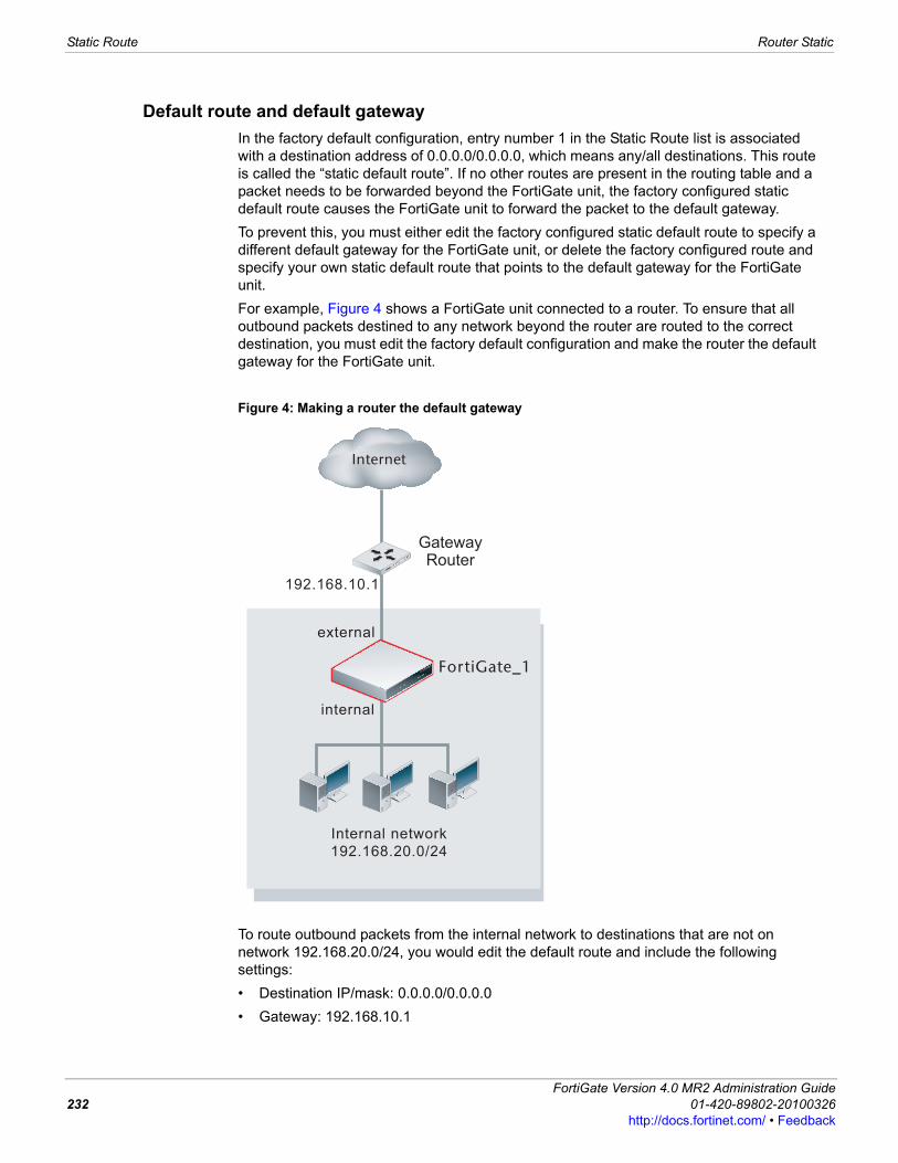
Static Route Router Static
Default route and default gateway In the factory default configuration, entry number 1 in the Static Route list is associated with a destination address of 0.0.0.0/0.0.0.0, which means any/all destinations. This route is called the “static default route”. If no other routes are present in the routing table and a packet needs to be forwarded beyond the FortiGate unit, the factory configured static default route causes the FortiGate unit to forward the packet to the default gateway. To prevent this, you must either edit the factory configured static default route to specify a different default gateway for the FortiGate unit, or delete the factory configured route and specify your own static default route that points to the default gateway for the FortiGate unit.For example, Figure 4 shows a FortiGate unit connected to a router. To ensure that all outbound packets destined to any network beyond the router are routed to the correct destination, you must edit the factory default configuration and make the router the default gateway for the FortiGate unit.
Figure 4: Making a router the default gateway
To route outbound packets from the internal network to destinations that are not on network 192.168.20.0/24, you would edit the default route and include the following settings:• Destination IP/mask: 0.0.0.0/0.0.0.0• Gateway: 192.168.10.1
Internal network
192.168.20.0/24
FortiGate_1
external
GatewayRouter
192.168.10.1
internal
Internet
FortiGate Version 4.0 MR2 Administration Guide232 01-420-89802-20100326
http://docs.fortinet.com/ • Feedback
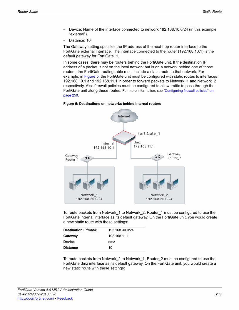
Router Static Static Route
F0h
• Device: Name of the interface connected to network 192.168.10.0/24 (in this example “external”).
• Distance: 10The Gateway setting specifies the IP address of the next-hop router interface to the FortiGate external interface. The interface connected to the router (192.168.10.1) is the default gateway for FortiGate_1.In some cases, there may be routers behind the FortiGate unit. If the destination IP address of a packet is not on the local network but is on a network behind one of those routers, the FortiGate routing table must include a static route to that network. For example, in Figure 5, the FortiGate unit must be configured with static routes to interfaces 192.168.10.1 and 192.168.11.1 in order to forward packets to Network_1 and Network_2 respectively. Also firewall policies must be configured to allow traffic to pass through the FortiGate unit along these routes. For more information, see “Configuring firewall policies” on page 258.
Figure 5: Destinations on networks behind internal routers
To route packets from Network_1 to Network_2, Router_1 must be configured to use the FortiGate internal interface as its default gateway. On the FortiGate unit, you would create a new static route with these settings:
To route packets from Network_2 to Network_1, Router_2 must be configured to use the FortiGate dmz interface as its default gateway. On the FortiGate unit, you would create a new static route with these settings:
Destination IP/mask 192.168.30.0/24
Gateway 192.168.11.1
Device dmz
Distance 10
Network_2
192.168.30.0/24
FortiGate_1
internal dmz
Gateway Router_1
192.168.10.1
Gateway Router_2
192.168.11.1
Internet
Network_1
192.168.20.0/24
ortiGate Version 4.0 MR2 Administration Guide1-420-89802-20100326 233ttp://docs.fortinet.com/ • Feedback
Static Route Router Static
Changing the gateway for the default routeThe default gateway determines where packets matching the default route will be forwarded. If you are using DHCP or PPPoE over a modem interface on your FortiGate unit, you may have problems configuring a static route on this interface. After trying to either renew your DHCP license, or reconnect the PPPoE connection, go to the CLI and enable dynamic-gateway under config system interface for the modem interface. This will remove the need to specify a gateway for this interface’s route. For more information, see FortiGate CLI Reference.
To change the gateway for the default route1 Go to Router > Static > Static Route.2 Select the Edit icon in row 1. 3 If the FortiGate unit reaches the next-hop router through an interface other than the
interface that is currently selected in the Device field, select the name of the interface from the Device field.
4 In the Gateway field, type the IP address of the next-hop router to which outbound traffic may be directed.
5 In the Distance field, optionally adjust the administrative distance value. The default route distance should be set high enough to allow other routes to be configured at lower distances so they will be preferred over the default route.
6 Select OK.
Adding a static route to the routing table A route provides the FortiGate unit with the information it needs to forward a packet to a particular destination. A static route causes packets to be forwarded to a destination other than the default gateway.You define static routes manually. Static routes control traffic exiting the FortiGate unit—you can specify through which interface the packet will leave and to which device the packet should be routed.
To add a static route entry1 Go to Router > Static > Static Route.2 Select Create New.3 Enter the IP address and netmask.
For example, 172.1.2.0/255.255.255.0 would be a route for all addresses on the subnet 172.1.2.x.
4 Enter the FortiGate unit interface closest to this subnet, or connected to it.
Destination IP/mask 192.168.20.0/24
Gateway 192.168.10.1
Device internal
Distance 10
Note: For network traffic to pass, even with the correct routes configured, you must have the appropriate firewall policies. For more information, see “Configuring firewall policies” on page 258.
FortiGate Version 4.0 MR2 Administration Guide234 01-420-89802-20100326
http://docs.fortinet.com/ • Feedback
Router Static ECMP route failover and load balancing
F0h
5 Enter the gateway IP address. Continuing with the example, 172.1.2.11 would be a valid address.
6 Enter the administrative distance of this route. The administrative distance allows you to weight one route to be preferred over another. This is useful when one route is unreliable. For example, if route A has an administrative distance of 30 and route B has an administrative distance of 10, the preferred route is route A with the smaller administrative distance of 10. If you discover that route A is unreliable, you can change the administrative distance for route A from 10 to 40, which will make the route B the preferred route.
7 Select OK to confirm and save your new static route.When you add a static route through the web-based manager, the FortiGate unit adds the entry to the Static Route list.Figure 172 shows the Edit Static Route dialog box belonging to a FortiGate unit that has an interface named “internal”. The names of the interfaces on your FortiGate unit may be different.
ECMP route failover and load balancingFortiOS uses equal-cost multi-path (ECMP) to distribute traffic to the same destination such as the Internet or another network. By using ECMP, you can add multiple routes to the same destination and give each of those routes the same distance and priority. However, if multiple routes to the same destination have the same priority but different distances, the route with the lowest distance is used. If multiple routes to the same destination have the same distance but different priorities, the route with the lowest priority is used. Distance takes precedence over priority. If multiple routes to the same destination have the different distances and different priorities, the route with the lowest distance is always used even if it has the highest priority.By using ECMP, if more than one ECMP route is available you can configure how the FortiGate unit selects the route to be used for a communication session. If only one ECMP route is available (for example, because an interface cannot process traffic because interface status detection does not receive a reply from the configured server) then all traffic uses this route.Previous versions of FortiOS provided source IP-based load balancing for ECMP routes. FortiOS 4.0 MR1 includes three configuration options for ECMP route failover and load balancing:
Destination IP/Mask
Type the destination IP address and network mask of packets that the FortiGate unit has to intercept. The value 0.0.0.0/0.0.0.0 is reserved for the default route.
Gateway Type the IP address of the next-hop router to which the FortiGate unit will forward intercepted packets.
Device Select the name of the FortiGate interface through which the intercepted packets may be routed to the next-hop router.
Distance Type an administrative distance from 1 to 255 for the route. The distance value is arbitrary and should reflect the distance to the next-hop router. A lower value indicates a more preferred route.
Weight Add weights for each route. Add higher weights to routes that you want to load balance more sessions to. See “Configuring weighted static route load balancing” on page 240.Available if ECMP Route Failover & Load Balance Method is set to weighted.
ortiGate Version 4.0 MR2 Administration Guide1-420-89802-20100326 235ttp://docs.fortinet.com/ • Feedback
ECMP route failover and load balancing Router Static
You can configure only one of these ECMP route failover and load balancing methods in a single VDOM. If your FortiGate unit is configured for multiple VDOM operation, each VDOM can have its own ECMP route failover and load balancing configuration.
To configure the ECMP route failover and load balancing method from the web-based manager1 Go to Router > Static > Static Route. 2 Set ECMP Route failover & Load Balance Method to source based, weighted, or
spill-over.3 Select Apply.
To configure the ECMP route failover and load balancing method from the CLIEnter the following command:config system settingsset v4-ecmp-mode {source-ip-based | usage-based |
weight-based}end
ECMP routing of simultaneous sessions to the same destination IP address
When the FortiGate unit selects an ECMP route for a session, a route cache is created that matches the route with the destination IP address of the session. All new sessions to the same destination IP address use the same route until the route is flushed from the cache. Routes are flushed from the cache after a period of time when no new sessions to the destination IP address are received. The route cache improves FortiGate routing performance by reducing how often the FortiGate unit looks up routes in the routing table.If the FortiGate unit receives a large number of sessions with the same destination IP address, because all of these sessions will be processed by the same route, it may appear that sessions are not distributed according to the ECMP route failover and load balancing configuration.
Source based (also called source IP based)
The FortiGate unit load balances sessions among ECMP routes based on the source IP address of the sessions to be load balanced. This is the default load balancing method. No configuration changes are required to support source IP load balancing.
Weighted (also called weight-based)
The FortiGate unit load balances sessions among ECMP routes based on weights added to ECMP routes. More traffic is directed to routes with higher weights.After selecting weight-based you must add weights to static routes. See “Configuring weighted static route load balancing” on page 240.
Spill-over (also called usage-based)
The FortiGate unit distributes sessions among ECMP routes based on how busy the FortiGate interfaces added to the routes are.After selecting spill-over, you add route Spillover Thresholds to interfaces added to ECMP routes. The FortiGate unit sends all ECMP-routed sessions to the lowest numbered interface until the bandwidth being processed by this interface reaches its spillover threshold. The FortiGate unit then spills additional sessions over to the next lowest numbered interface.The Spillover Thresholds range is 0-2097000 KBps.For more information, including the order in which interfaces are selected, see “Configuring spill-over or usage-based ECMP” on page 237.
FortiGate Version 4.0 MR2 Administration Guide236 01-420-89802-20100326
http://docs.fortinet.com/ • Feedback
Router Static ECMP route failover and load balancing
F0h
Configuring spill-over or usage-based ECMPThe spill-over or usage-based ECMP method routes new sessions to interfaces that have not reached a configured bandwidth limit (called the Spillover Threshold or a route-spillover threshold). To configure spill-over or usage-based ECMP routing, you enable spill-over ECMP method, add ECMP routes, and add a Spillover Threshold to the interfaces used by the ECMP routes. Set the Spillover Thresholds to limit the amount of bandwidth processed by each interface. With spill-over ECMP routing configured, the FortiGate unit routes new sessions to an interface used by an ECMP route until that interface reaches its Spillover Threshold. Then, when the threshold of that interface is reached, new sessions are routed to one of the other interfaces used by the ECMP routes. Use the following procedure to enable usage based ECMP routing, add Spillover Thresholds to FortiGate interfaces port3 and port4, and then to configure EMCP routes with device set to port3 and port4.
To add Spillover Thresholds to interfaces from the web-based manager1 Go to Router > Static > Static Route. 2 Set ECMP Route failover & Load Balance Method to usage-based. 3 Go to Router > Static > Static Route.4 Add ECMP routes for port3 and port4.
5 Go to System > Network > Interface.6 Edit port3 and port4 and add the following spillover-thresholds:
7 Go to Router > Monitor to view the routing table.The routes could be displayed in the order shown in Table 45.
Destination IP/Mask 192.168.20.0/24
Device port3
Gateway 172.20.130.3
Distance 9
Destination IP/Mask 192.168.20.0/24
Device port4
Gateway 172.20.140.4
Distance 9
Interface port3
Spillover Threshold (KBps) 100
Interface port4
Spillover Threshold (KBps) 200
Table 45: Example ECMP routes as listed on the routing monitor
Type Network Distance Metric Gateway InterfaceStatic 192.168.20.0/24 9 0 172.20.130.3 port3
Static 192.168.20.0/24 9 0 172.20.140.4 port4
ortiGate Version 4.0 MR2 Administration Guide1-420-89802-20100326 237ttp://docs.fortinet.com/ • Feedback
ECMP route failover and load balancing Router Static
In this example, the FortiGate unit sends all sessions to the 192.168.20.0 network through port3. When port3 exceeds its spillover threshold of 100 Kbps the FortiGate unit sends all new sessions to the 192.168.20.0 network through port4.
To add route-spillover thresholds to interfaces from the CLI1 Enter the following command to set the ECMP route failover and load balance method
to usage-based.config system settingsset v4-ecmp-mode usage-based
end
2 Enter the following commands to add three route-spillover thresholds to three interfaces.config system interfaceedit port1set spillover-threshold 400
nextedit port2set spillover-threshold 200
nextedit port3set spillover-threshold 100
end
3 Enter the following commands to add three ECMP default routes, one for each interface.config router staticedit 1set dst 0.0.0.0/0.0.0.0set gwy 172.20.110.1set dev port1
nextedit 2set dst 0.0.0.0/0.0.0.0set gwy 172.20.120.2set dev port2
nextedit 3set dst 0.0.0.0/0.0.0.0set gwy 172.20.130.3set dev port3
end
4 Enter the following command to display static routes in the routing table:get router info routing-table staticS 0.0.0.0/0 [10/0] via 172.20.110.1, port1
[10/0] via 172.20.120.2, port2[10/0] via 172.20.130.3, port3
In this example, the FortiGate unit sends all sessions to the Internet through port1. When port1 exceeds its spillover threshold of 400 KBps the FortiGate unit sends all new sessions to the Internet through port2. If both port1 and port2 exceed their spillover thresholds the FortiGate unit would send all new sessions to the Internet through port3.
FortiGate Version 4.0 MR2 Administration Guide238 01-420-89802-20100326
http://docs.fortinet.com/ • Feedback
Router Static ECMP route failover and load balancing
F0h
Detailed description of how spill-over ECMP selects routesWhen you add ECMP routes they are added to the routing table in the order displayed by the routing monitor or by the get router info routing-table static command. This order is independent of the configured bandwidth limit.The FortiGate unit selects an ECMP route for a new session by finding the first route in the routing table then sends the session out on a FortiGate interface that is not processing more traffic that its configured route spill-over limit.For example, consider a FortiGate unit with interfaces port3 and port4 both connected to the Internet through different ISPs. ECMP routing is set to usage-based and route spillover for to 100 KBps for port3 and 200 KBps for port4. Two ECMP default routes are added, one for port3 and one for port4.If the route to port3 is higher in the routing table than the route to port4, the FortiGate unit sends all default route sessions out port3 until port3 is processing 100 KBps of data. When port3 reaches its configured bandwidth limit, the FortiGate unit sends all default route sessions out port4. When the bandwidth usage of port3 falls below 100 KBps, the FortiGate again sends all default route sessions out port3.New sessions to designating IP addresses that are already in the routing cache; however, use the cached routes. This means that even of port3 is exceeding its bandwidth limit, new sessions can continue to be sent out port3 if their destination addresses are already in the routing cache. As a result, new sessions are sent out port4 only if port3 exceeds its bandwidth limit and if the routing cache does not contain a route for the destination IP address of the new session. The limit on port4 is important only if there are additional interfaces for spillover.Also, the switchover to port4 does not occur as soon as port3 exceeds its bandwidth limit. Bandwidth usage has to exceed the limit for a period of time before the switchover takes place. If port3 bandwidth usage drops below the bandwidth limit during this time period, sessions are not switched over to port4. This delay reduces route flapping. Route flapping occurs when routes change their status frequently, forcing routers to continually change their routing tables and broadcast the new information.FortiGate usage-based ECMP routing is not actually load balancing, since routes are not distributed evenly among FortiGate interfaces. Depending on traffic volumes, most traffic would usually be processed by the first interface with only spillover traffic being processed by other interfaces.If you are configuring usage-based ECMP, in most cases, you should add spillover thresholds to all of the interfaces with ECMP routes. The default spillover threshold is 0 which means no bandwidth limiting. If any interface has a spillover threshold of 0, no sessions will be routed to interfaces lower in the list unless the interface goes down or is disconnected. An interface can go down if Detect interface status for Gateway Load Balancing does not receive a response from the configured server.
Determining of a interface has exceeded its Spillover ThresholdYou can use the diagnose netlink dstmac list CLI command to determine if an interface is exceeding its Spillover Threshold. If the command displays over_bps=1 the interface is exceeding its threshold. If over_bps=0 the interface has not exceeded its threshold.
Note: A new session to a destination IP address that already has an entry in the routing cache is routed using the route already added to the cache for that destination address. For more information, see “ECMP routing of simultaneous sessions to the same destination IP address” on page 236.
ortiGate Version 4.0 MR2 Administration Guide1-420-89802-20100326 239ttp://docs.fortinet.com/ • Feedback
ECMP route failover and load balancing Router Static
Configuring weighted static route load balancingConfigure weighted load balancing to control how the FortiGate unit distributes sessions among ECMP routes by adding weights for each route. Add higher weights to routes that you want to load balance more sessions to. If no weight has been assigned to a route, its weight is set to zero by default.With the ECMP load balancing method set to weighted, the FortiGate unit distributes sessions with different destination IPs by generating a random value to determine the route to select. The probability of selecting one route over another is based on the weight value of each route. Routes with higher weights are more likely to be selected.Large numbers of sessions are evenly distributed among ECMP routes according to the route weight values. If all weights are the same, sessions are distributed evenly. The distribution of a small number of sessions however, may not be even. For example, its possible that if there are two ECMP routes with the same weight, two sessions to different IP addresses could use the same route. On the other hand 10,000 sessions with different destination IPs should be load balanced evenly between two routes with equal rates. The distribution could be 5000:5000 or 5001:4999. Also, 10,000 sessions with different destination IP addresses should be load balanced in the following way if the weights for the two routes are 100 and 200: 3333:6667.Weights only affect how routes are selected for sessions to new destination IP addresses. New sessions to IP addresses already in the routing cache are routed using the route for the session already in the cache. So in practice sessions will not always be distributed according to the routing weight distribution.
To add weights to static routes from the web-based manager1 Go to Router > Static > Static Route. 2 Set ECMP Route failover & Load Balance Method to weighted. 3 Go to Router > Static > Static Route.4 Add new or edit static routes and add weights to them.
The following example shows two ECMP routes with weights added.
In this example:• one third of the sessions to the 192.168.20.0 network will use the first route and be
sent out port1 to the gateway with IP address 172.20.110.1.• the other two thirds of the sessions to the 192.168.20.0 network will use the second
route and be sent out port2 to the gateway with IP address 172.20.120.2.
Destination IP/Mask 192.168.20.0/24
Device port1
Gateway 172.20.110.1
Distance 10
Weight 100
Destination IP/Mask 192.168.20.0/24
Device port2
Gateway 172.20.120.2
Distance 10
Weight 200
FortiGate Version 4.0 MR2 Administration Guide240 01-420-89802-20100326
http://docs.fortinet.com/ • Feedback

Router Static Policy Route
F0h
To add weights to static routes from the CLI1 Enter the following command to set the ECMP route failover and load balance method
to weighted.config system settingsset v4-ecmp-mode weight-based
end
2 Enter the following commands to add three ECMP static routes and add weights to each route.config router staticedit 1set dst 192.168.20.0/24set gwy 172.20.110.1set dev port1set weight 100
nextedit 2set dst 192.168.20.0/24set gwy 172.20.120.2set dev port2set weight 200
nextedit 3set dst 192.168.20.0/24set gwy 172.20.130.3set dev port3set weight 300
end
In this example:• one sixth of the sessions to the 192.168.20.0 network will use the first route and be
sent out port1 to the gateway with IP address 172.20.110.1.• one third of the sessions to the 192.168.20.0 network will use the second route and be
sent out port2 to the gateway with IP address 172.20.120.2.• one half of the sessions to the 192.168.20.0 network will use the third route and be
sent out port3 to the gateway with IP address 172.20.130.3.
Policy Route A routing policy allows you to redirect traffic away from a static route. This can be useful if you want to route certain types of network traffic differently. You can use incoming traffic’s protocol, source address or interface, destination address, or port number to determine where to send the traffic. For example, generally network traffic would go to the router of a subnet, but you might want to direct SMTP or POP3 traffic addressed to that subnet directly to the mail server.
Note: In this example the priority remains set to 0 and the distance remains set to 10 for all three routes. Any other routes with a distance set to 10 will not have their weight set, so will have a weight of 0 and will not be part of the load balancing.
ortiGate Version 4.0 MR2 Administration Guide1-420-89802-20100326 241ttp://docs.fortinet.com/ • Feedback
Policy Route Router Static
If you have configured the FortiGate unit with routing policies and a packet arrives at the FortiGate unit, the FortiGate unit starts at the top of the Policy Route list and attempts to match the packet with a policy. If a match is found, and the policy contains enough information to route the packet (a minimum of the IP address of the next-hop router and the FortiGate interface for forwarding packets to it), the FortiGate unit routes the packet using the information in the policy. If no policy route matches the packet, the FortiGate unit routes the packet using the routing table.Most policy settings are optional, so a matching policy alone might not provide enough information for forwarding the packet. The FortiGate unit may refer to the routing table in an attempt to match the information in the packet header with a route in the routing table. For example, if the outgoing interface is the only item in the policy, the FortiGate unit looks up the IP address of the next-hop router in the routing table. This situation could happen when the interfaces are dynamic (such as DHCP or PPPoE) and you do not want or are unable to specify the IP address of the next-hop router.Policy route options define which attributes of a incoming packet cause policy routing to occur. If the attributes of a packet match all the specified conditions, the FortiGate unit routes the packet through the specified interface to the specified gateway.To add a policy route, go to Router > Static > Policy Route and select Create New.For more information on Type of Service, see “Type of Service” on page 243.Figure shows the policy route list belonging to a FortiGate unit that has interfaces named “external” and “internal”. The names of the interfaces on your FortiGate unit may be different.
Policy Route pageLists all policy routes that you have created. On this page, you can edit, delete or create a new policy route.
Create New Add a policy route. See “Example policy route” on page 243.
# The ID numbers of configured route policies. These numbers are sequential unless policies have been moved within the table.
Incoming The interfaces on which packets subjected to route policies are received.
Outgoing The interfaces through which policy routed packets are routed.
Source The IP source addresses and network masks that cause policy routing to occur.
Destination The IP destination addresses and network masks that cause policy routing to occur.
Delete Delete a policy route.
Edit Edit a policy route.
New Routing Policy pageProvides settings for configuring how to redirect traffic away from the static route.
If incoming traffic matches: Protocol To perform policy routing based on the value in the protocol field of the
packet, enter the protocol number to match. The Internet Protocol Number is found in the IP packet header. RFC 5237 describes protocol numbers and you can find a list of the assigned protocol numbers here. The range is from 0 to 255. A value of 0 disables the feature.Tip: Commonly used Protocol settings include 6 to route TCP sessions, 17 for UDP sessions, 1 for ICMP sessions, 47 for GRE sessions, and 92 for multicast sessions.For protocols other than 6 and 17, the port number is ignored.
FortiGate Version 4.0 MR2 Administration Guide242 01-420-89802-20100326
http://docs.fortinet.com/ • Feedback
Router Static Policy Route
F0h
•
Example policy routeConfigure the following policy route to send all FTP traffic received at port1 out the port10 interface and to a next hop router at IP address 172.20.120.23. To route FTP traffic set protocol to 6 (for TCP) and set both of the destination ports to 21, the FTP port.
Type of ServiceType of service (TOS) is an 8-bit field in the IP header that enables you to determine how the IP datagram should be delivered, with such qualities as delay, priority, reliability, and minimum cost. Each quality helps gateways determine the best way to route datagrams. A router maintains a ToS value for each route in its routing table.The lowest priority TOS is 0, the highest is 7 - when bits 3, 4,and 5 are all set to 1. The router tries to match the TOS of the datagram to the TOS on one of the possible routes to the destination. If there is no match, the datagram is sent over a zero TOS route. Using increased quality may increase the cost of delivery because better performance may consume limited network resources. For more information, see RFC 791 and RFC 1349.
Incoming interface Select the name of the interface through which incoming packets subjected to the policy are received.
Source address/mask To perform policy routing based on the IP source address of the packet, type the source address and network mask to match. A value of 0.0.0.0/0.0.0.0 disables the feature.
Destination address/mask
To perform policy routing based on the IP destination address of the packet, type the destination address and network mask to match. A value of 0.0.0.0/0.0.0.0 disables the feature.
Destination ports To perform policy routing based on the port on which the packet is received, type the same port number in the From and To fields. To apply policy routing to a range of ports, type the starting port number in the From field and the ending port number in the To field. A value of 0 disables this feature.The Destination Ports fields are only used for TCP and UDP protocols. The ports are skipped over for all other protocols.
Type of Service Use a two digit hexadecimal bit pattern to match the service, or use a two digit hexadecimal bit mask to mask out. For more information, see “Type of Service” on page 243.
Force traffic to: Outgoing interface Select the name of the interface through which packets affected by the
policy will be routed.
Gateway Address Type the IP address of the next-hop router that the FortiGate unit can access through the specified interface. A value of 0.0.0.0 is not valid.
Protocol 6
Incoming interface port1
Source address / mask 0.0.0.0/0.0.0.0
Destination address / mask 0.0.0.0/0.0.0.0
Destination Ports From 21 to 21
Type of Service bit pattern: 00 (hex) bit mask: 00 (hex)
Outgoing interface port10
Gateway Address 172.20.120.23
ortiGate Version 4.0 MR2 Administration Guide1-420-89802-20100326 243ttp://docs.fortinet.com/ • Feedback
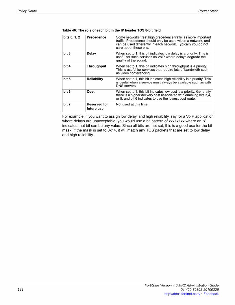
Policy Route Router Static
For example, if you want to assign low delay, and high reliability, say for a VoIP application where delays are unacceptable, you would use a bit pattern of xxx1x1xx where an ‘x’ indicates that bit can be any value. Since all bits are not set, this is a good use for the bit mask; if the mask is set to 0x14, it will match any TOS packets that are set to low delay and high reliability.
Table 46: The role of each bit in the IP header TOS 8-bit field
bits 0, 1, 2 Precedence Some networks treat high precedence traffic as more important traffic. Precedence should only be used within a network, and can be used differently in each network. Typically you do not care about these bits.
bit 3 Delay When set to 1, this bit indicates low delay is a priority. This is useful for such services as VoIP where delays degrade the quality of the sound.
bit 4 Throughput When set to 1, this bit indicates high throughput is a priority. This is useful for services that require lots of bandwidth such as video conferencing.
bit 5 Reliability When set to 1, this bit indicates high reliability is a priority. This is useful when a service must always be available such as with DNS servers.
bit 6 Cost When set to 1, this bit indicates low cost is a priority. Generally there is a higher delivery cost associated with enabling bits 3,4, or 5, and bit 6 indicates to use the lowest cost route.
bit 7 Reserved for future use
Not used at this time.
FortiGate Version 4.0 MR2 Administration Guide244 01-420-89802-20100326
http://docs.fortinet.com/ • Feedback
Router Dynamic RIP
F0h
Router DynamicThis section introduces you to the dynamic routing in the Routing menu. For more information about dynamic routing, see the Dynamic Routing chapter in the FortiOS Handbook. Dynamic routing protocols enable the FortiGate unit to automatically share information about routes with neighboring routers and learn about routes and networks advertised by them. The FortiGate unit supports these dynamic routing protocols:• Routing Information Protocol (RIP)• Open Shortest Path First (OSPF)• Border Gateway Protocol (BGP).
If you enable virtual domains (VDOMs) on the FortiGate unit, dynamic routing is configured separately for each virtual domain. For more information, see “Using virtual domains” on page 73.
The following topics are included in this section:• RIP• OSPF• BGP• Multicast• Bi-directional Forwarding Detection (BFD)
RIPRouting Information Protocol (RIP) is a distance-vector routing protocol intended for small, relatively homogeneous networks. The FortiGate implementation of RIP supports RIP version 1 (see RFC 1058) and RIP version 2 (see RFC 2453). RIP is configured in Routing > Dynamic > RIP.
Note: A FortiGate unit can operate as a Protocol Independent Multicast (PIM) version 2 router in the root virtual domain. FortiGate units support PIM sparse mode and dense mode and can service multicast servers or receivers on the network segment to which a FortiGate interface is connected. PIM can use static routes, RIP, OSPF, or BGP to forward multicast packets to their destinations.
RIP page Lists all the networks and interfaces that you have created. This page also allows you to configure basic RIP settings, including creating interfaces and networks.
RIP Version Select the level of RIP compatibility needed at the FortiGate unit. You can enable global RIP settings on all FortiGate interfaces connected to RIP-enabled networks:1 – send and receive RIP version 1 packets.2 – send and receive RIP version 2 packets.You can override the global settings for a specific FortiGate interface if required. For more information, see “RIP-enabled interface” on page 247.
ortiGate Version 4.0 MR2 Administration Guide1-420-89802-20100326 245ttp://docs.fortinet.com/ • Feedback
RIP Router Dynamic
Advanced RIP optionsWith advanced RIP options, you can specify settings for RIP timers and define metrics for redistributing routes that the FortiGate unit learns through some means other than RIP updates. For example, if the unit is connected to an OSPF or BGP network or you add a static route to the FortiGate routing table manually, you can configure the unit to advertise those routes on RIP-enabled interfaces.You can configure additional advanced options through customizable GUI widgets, and the CLI. For example, you can filter incoming or outgoing updates by using a route map, an access list, or a prefix list. The FortiGate unit also supports offset lists, which add the specified offset to the metric of a route. For more information on customizable GUI widgets, see “” on page 258. For more information on CLI routing commands, see the “router” chapter of the FortiGate CLI Reference.Advanced RIP options are configured in Router > Dynamic > RIP, in the Advanced Options are of the page. You must expand Advanced Options to reveal the hidden settings so that you can configure these advanced options.
Advanced Options Select the Expand Arrow to view or hide advanced RIP options. For more information, see “Advanced RIP options” on page 246.
Networks section of the RIP pageThe IP addresses and network masks of the major networks (connected to the FortiGate unit) that run RIP. When you add a network to the Networks list, the FortiGate interfaces that are part of the network are advertised in RIP updates. You can enable RIP on all FortiGate interfaces whose IP addresses match the RIP network address space.
IP/Netmask Enter the IP address and netmask that defines the RIP-enabled network.
Add Select to add the network information to the Networks list.
Delete Select to remove a network from the RIP network list.
Interfaces section of the RIP pageAny additional settings needed to adjust RIP operation on a FortiGate interface.
Create New Add new RIP operating parameters for an interface. These parameters will override the global RIP settings for that interface. For more information, see “RIP-enabled interface” on page 247.
Interface The name of the unit RIP interface.
Send Version The version of RIP used to send updates through each interface: 1, 2, or both.
Receive Version The versions of RIP used to listen for updates on each interface: 1, 2, or both.
Authentication The type of authentication used on this interface: None, Text or MD5.
Passive Permissions for RIP broadcasts on this interface. A green checkmark means the RIP broadcasts are blocked.
Edit Select to modify the settings of a RIP Interface.
Delete Select to remove a RIP interface from the RIP Interface list.
Advanced Options section of the RIP pageAdvanced Options Select the Expand Arrow to view or hide advanced options.
Default Metric Enter the default hop count that the FortiGate unit should assign to routes that are added to the FortiGate routing table. The range is from 1 to 16. This metric is the hop count, with 1 being best or shortest.This value also applies to Redistribute unless otherwise specified.
Default-information-originate
Select to generate and advertise a default route into the FortiGate unit’s RIP-enabled networks. The generated route may be based on routes learned through a dynamic routing protocol, routes in the routing table, or both.
FortiGate Version 4.0 MR2 Administration Guide246 01-420-89802-20100326
http://docs.fortinet.com/ • Feedback
Router Dynamic RIP
F0h
RIP-enabled interfaceYou can use RIP interface options to override the global RIP settings that apply to all FortiGate unit interfaces connected to RIP-enabled networks. For example, if you want to suppress RIP advertising on an interface that is connected to a subnet of a RIP-enabled network, you can set the interface to operate passively. Passive interfaces listen for RIP updates but do not respond to RIP requests.If RIP version 2 is enabled on the interface, you can optionally choose password authentication to ensure that the FortiGate unit authenticates a neighboring router before accepting updates from that router. The unit and the neighboring router must both be configured with the same password. Authentication guarantees the authenticity of the update packet, not the confidentiality of the routing information in the packet.RIP-enabled interfaces are configured in Router > Dynamic > RIP.
RIP Timers Enter new values to override the default RIP timer settings. The default settings are effective in most configurations — if you change these settings, ensure that the new settings are compatible with local routers and access servers.If the Update timer is smaller than Timeout or Garbage timers, you will get an error.
Update Enter the amount of time (in seconds) that the FortiGate unit will wait between sending RIP updates.
Timeout Enter the maximum amount of time (in seconds) that a route is considered reachable while no updates are received for the route. This is the maximum time the FortiGate unit will keep a reachable route in the routing table while no updates for that route are received. If the FortiGate unit receives an update for the route before the timeout period expires, the timer is restarted.The Timeout period should be at least three times longer than the Update period.
Garbage Enter the amount of time (in seconds) that the FortiGate unit will advertise a route as being unreachable before deleting the route from the routing table. The value determines how long an unreachable route is kept in the routing table.
Redistribute Select one or more of the options to redistribute RIP updates about routes that were not learned through RIP. The FortiGate unit can use RIP to redistribute routes learned from directly connected networks, static routes, OSPF, and BGP.
Connected Select to redistribute routes learned from directly connected networks. To specify a hop count for those routes, select Metric, and enter the hop count in the Metric field. The valid hop count range is from 1 to 16.
Static Select to redistribute routes learned from static routes. To specify a hop count for those routes, select Metric, and enter the hop count in the Metric field. The range is from 1 to 16.
OSPF Select to redistribute routes learned through OSPF. To specify a hop count for those routes, select Metric, and enter the hop count in the Metric field. The range is from 1 to 16.
BGP Select to redistribute routes learned through BGP. To specify a hop count for those routes, select Metric, and enter the hop count in the Metric field. The range is from 1 to 16.
Note: Additional options such as split-horizon and key-chains can be configured per interface through the CLI. For more information, see the router chapter of the FortiGate CLI Reference.
ortiGate Version 4.0 MR2 Administration Guide1-420-89802-20100326 247ttp://docs.fortinet.com/ • Feedback

OSPF Router Dynamic
OSPFOpen Shortest Path First (OSPF) is a link-state routing protocol that is most often used in large heterogeneous networks to share routing information among routers in the same Autonomous System (AS). FortiGate units support OSPF version 2 (see RFC 2328).The main benefit of OSPF is that it advertises routes only when neighbors change state instead of at timed intervals, so routing overhead is reduced. • This topic contains the following: Defining an OSPF AS—Overview• Basic OSPF settings• Advanced OSPF options• Defining OSPF areas• OSPF networks• Operating parameters for an OSPF interface
Defining an OSPF AS—OverviewDefining an OSPF Autonomous System (AS), involves:• defining the characteristics of one or more OSPF areas• creating associations between the OSPF areas that you defined and the local networks
to include in the OSPF AS• if required, adjusting the settings of OSPF-enabled interfaces.If you are using the web-based manager to perform these tasks, follow the procedures summarized below.
Basic OSPF settingsWhen you configure OSPF settings, you have to define the AS in which OSPF is enabled and specify which of the FortiGate interfaces participate in the AS. As part of the AS definition, you specify the AS areas and specify which networks to include those areas. You may optionally adjust the settings associated with OSPF operation on the FortiGate interfaces.
New/Edit RIP Interface pageProvides settings for configuring a RIP Interface. When you select Create New in the Interfaces section of the RIP page, you are automatically redirected to the New/Edit RIP Interface page.
Interface Select the name of the FortiGate interface to which these settings apply. The interface must be connected to a RIP-enabled network. The interface can be a virtual IPSec or GRE interface.
Send Version,Receive Version
Select to override the default RIP-compatibility setting for sending and receiving updates through the interface: RIP version 1, version 2 or Both.
Authentication Select an authentication method for RIP exchanges on the specified interface: None — Disable authentication.Text — Select if the interface is connected to a network that runs RIP version 2. Type a password (up to 35 characters) in the Password field. The FortiGate unit and the RIP updates router must both be configured with the same password. The password is sent in clear text over the network.MD5 — Authenticate the exchange using MD5.
Password Enter the password for authentication.
Passive Interface Select to suppress the advertising of FortiGate unit routing information over the specified interface. Clear the check box to allow the interface to respond normally to RIP requests.
FortiGate Version 4.0 MR2 Administration Guide248 01-420-89802-20100326
http://docs.fortinet.com/ • Feedback
Router Dynamic OSPF
F0h
OSPF settings are configured in Router > Dynamic > OSPF.
OSPF pageLists all areas, networks and interfaces that you created for OSPF.
Router ID Enter a unique router ID to identify the FortiGate unit to other OSPF routers. By convention, the router ID is the numerically highest IP address assigned to any of the FortiGate interfaces in the OSPF AS. If you change the router ID while OSPF is configured on an interface, all connections to OSPF neighbors will be broken temporarily. The connections will re-establish themselves.If Router ID is not explicitly set, the highest IP address of the VDOM or unit will be used.
Advanced Options Select the Expand Arrow to view or hide advanced OSPF settings. For more information, see “Advanced OSPF options” on page 250.
Areas section of the OSPF pageInformation about the areas making up an OSPF AS. The header of an OSPF packet contains an area ID, which helps to identify the origination of a packet inside the AS.
Create New Define and add a new OSPF area to the Areas list. For more information, see “Defining OSPF areas” on page 251.
Edit Select to modify settings of an area.
Delete Select to remove an area from the Areas list.
Area The unique 32-bit identifiers of areas in the AS, in dotted-decimal notation. Area ID 0.0.0.0 references the backbone of the AS and cannot be changed or deleted.
Type The types of areas in the AS:• Regular - a normal OSPF area• NSSA - a not so stubby area• Stub - a stub area.For more information, see “Defining OSPF areas” on page 251.
Authentication The methods for authenticating OSPF packets sent and received through all FortiGate interfaces linked to each area: None — authentication is disabledText — text-based authentication is enabledMD5 — MD5 authentication is enabled. A different authentication setting may apply to some of the interfaces in an area, as displayed under Interfaces. For example, if an area employs simple passwords for authentication, you can configure a different password for one or more of the networks in that area.
Networks section of the OSPF pageThe networks in the OSPF AS and their area IDs. When you add a network to the Networks list, all FortiGate interfaces that are part of the network are advertised in OSPF link-state advertisements. You can enable OSPF on all FortiGate interfaces whose IP addresses match the OSPF network address space. For more information, see “OSPF networks” on page 252.
Create New Add a network to the AS, specify its area ID, and add the definition to the Networks list.
Edit Select to modify settings of an area.
Delete Select to remove an area from the Areas list.
Network The IP addresses and network masks of networks in the AS on which OSPF runs. The FortiGate unit may have physical or VLAN interfaces connected to the network.
Area The area IDs that have been assigned to the OSPF network address space.
Interfaces section of the OSPF pageAny additional settings needed to adjust OSPF operation on a FortiGate interface. For more information, see “Operating parameters for an OSPF interface” on page 252.
Create New Create additional/different OSPF operating parameters for a unit interface and add the configuration to the Interfaces list.
ortiGate Version 4.0 MR2 Administration Guide1-420-89802-20100326 249ttp://docs.fortinet.com/ • Feedback
OSPF Router Dynamic
Advanced OSPF optionsBy selecting advanced OSPF options, you can specify metrics for redistributing routes that the FortiGate unit learns through some means other than OSPF link-state advertisements. For example, if the FortiGate unit is connected to a RIP or BGP network or you add a static route to the FortiGate routing table manually, you can configure the unit to advertise those routes on OSPF-enabled interfaces.You can configure additional advanced options through customizable GUI widgets, and the CLI. For example, you can filter incoming or outgoing updates by using a route map, an access list, or a prefix list. The FortiGate unit also supports offset lists, which add the specified offset to the metric of a route. For more information on customizable GUI widgets, see “” on page 258. For more information on CLI routing commands, see the “router” chapter of the FortiGate CLI Reference.Advanced OSPF options are located in Router > Dynamic > RIP. You must expand the Advanced Options on the page to access these options.
Edit Select to modify settings of an area.
Delete Select to remove an area from the Areas list.
Name The names of OSPF interface definitions.
Interface The names of FortiGate physical or VLAN interfaces having OSPF settings that differ from the default values assigned to all other interfaces in the same area.
IP The IP addresses of the OSPF-enabled interfaces having additional/different settings.
Authentication The methods for authenticating LSA exchanges sent and received on specific OSPF-enabled interfaces. These settings override the area Authentication settings.
Advanced Options on the OSPF pageRouter ID Enter a unique router ID to identify the FortiGate unit to other OSPF routers.
Expand Arrow Select to view or hide Advanced Options.
Default Information Generate and advertise a default (external) route to the OSPF AS. You may base the generated route on routes learned through a dynamic routing protocol, routes in the routing table, or both.
None Prevent the generation of a default route.
Regular Generate a default route into the OSPF AS and advertise the route to neighboring autonomous systems only if the route is stored in the FortiGate routing table.
Always Generate a default route into the OSPF AS and advertise the route to neighboring autonomous systems unconditionally, even if the route is not stored in the FortiGate routing table.
Redistribute Select one or more of the options listed to redistribute OSPF link-state advertisements about routes that were not learned through OSPF. The FortiGate unit can use OSPF to redistribute routes learned from directly connected networks, static routes, RIP, and BGP.
Connected Select to redistribute routes learned from directly connected networks.Enter a cost for those routes in the Metric field. The range is from 1 to 16 777 214.
Static Select to redistribute routes learned from static routes.Enter a cost for those routes in the Metric field. The range is from 1 to 16 777 214.
FortiGate Version 4.0 MR2 Administration Guide250 01-420-89802-20100326
http://docs.fortinet.com/ • Feedback
Router Dynamic OSPF
F0h
Defining OSPF areasAn area logically defines part of the OSPF AS. Each area is identified by a 32-bit area ID expressed in dotted-decimal notation, for example 192.168.0.1. Area ID 0.0.0.0 is reserved for the OSPF network backbone. You can classify the remaining areas of an AS as regular, stub, or NSSA.A regular area contains more than one router, each having at least one OSPF-enabled interface to the area.To reach the OSPF backbone, the routers in a stub area must send packets to an area border router. Routes leading to non-OSPF domains are not advertised to the routers in stub areas. The area border router advertises to the OSPF AS a single default route (destination 0.0.0.0) into the stub area, which ensures that any OSPF packet that cannot be matched to a specific route will match the default route. Any router connected to a stub area is considered part of the stub area.In a Not-So-Stubby Area (NSSA), routes that lead out of the area into a non-OSPF domain are made known to OSPF AS. However, the area itself continues to be treated like a stub area by the rest of the AS.Regular areas and stub areas (including not-so-stubby areas) are connected to the OSPF backbone through area border routers. Defining an OSPF is configured in Router > Dynamic > OSPF.
RIP Select to redistribute routes learned through RIP.Enter a cost for those routes in the Metric field. The range is from 1 to 16 777 214.
BGP Select to redistribute routes learned through BGP.Enter a cost for those routes in the Metric field. The range is from 1 to 16 777 214.
Note: If required, you can define a virtual link to an area that has lost its physical connection to the OSPF backbone. Virtual links can be set up only between two FortiGate units that act as area border routers. For more information on virtual links, see the FortiGate CLI Reference.
New/Edit OSPF Area pageProvides settings for defining an OSPF area. When you select Create New in the Areas section of the OSPF page, you are automatically redirected to the New/Edit OSPF Area page.
Area Type a 32-bit identifier for the area. The value must resemble an IP address in dotted-decimal notation. Once you have created the OSPF area, the area IP value cannot be changed; you must delete the area and restart.
ortiGate Version 4.0 MR2 Administration Guide1-420-89802-20100326 251ttp://docs.fortinet.com/ • Feedback
OSPF Router Dynamic
OSPF networksOSPF areas group a number of contiguous networks together. When you assign an area ID to a network address space, the attributes of the area are associated with the network.Assigning an OSPF area ID to a network is configured in Router > Dynamic > OSPF. You must be in the Network section of the page to assign an OSPF area ID to a network.
Operating parameters for an OSPF interfaceAn OSPF interface definition contains specific operating parameters for a FortiGate OSPF-enabled interface. The definition includes the name of the interface (for example, external or VLAN_1), the IP address assigned to the interface, the method for authenticating LSA exchanges through the interface, and timer settings for sending and receiving OSPF Hello and dead-interval packets.You can enable OSPF on all FortiGate interfaces whose IP addresses match the OSPF-enabled network space. For example, define an area of 0.0.0.0 and the OSPF network as 10.0.0.0/16. Then define vlan1 as 10.0.1.1/24, vlan2 as 10.0.2.1/24 and vlan3 as 10.0.3.1/24. All three VLANs can run OSPF in area 0.0.0.0. To enable all interfaces, you would create an OSPF network 0.0.0.0/0 When entering the operating parameters for MD5 keys for the interface, the following special characters are not supported:
Type Select an area type to classify the characteristics of the network that will be assigned to the area:Regular — If the area contains more than one router, each having at least one OSPF-enabled interface to the area.NSSA — If you want routes to external non-OSPF domains made known to OSPF AS and you want the area to be treated like a stub area by the rest of the AS.STUB — If the routers in the area must send packets to an area border router in order to reach the backbone and you do not want routes to non-OSPF domains to be advertised to the routers in the area.
Authentication Select the method for authenticating OSPF packets sent and received through all interfaces in the area:None — Disable authentication.Text — Enables text-based password authentication. to authenticate LSA exchanges using a plain-text password. The password is sent in clear text over the network.MD5 — Enable MD5-based authentication using an MD5 cryptographic hash (RFC 1321).If required, you can override this setting for one or more of the interfaces in the area. For more information, see “Operating parameters for an OSPF interface” on page 252.
New/Edit OSPF Network pageProvides settings for configuring networks that are assigned to an area ID. When you select Create New in the Network section of the OSPF page, you are automatically redirected to the New/Edit OSPF Network page.
IP/Netmask Enter the IP address and network mask of the local network that you want to assign to an OSPF area.
Area Select an area ID for the network. The attributes of the area must match the characteristics and topology of the specified network. You must define the area before you can select the area ID. For more information, see “Defining OSPF areas” on page 251.
• < > • #
• ( ) • “
• ‘
FortiGate Version 4.0 MR2 Administration Guide252 01-420-89802-20100326
http://docs.fortinet.com/ • Feedback
Router Dynamic OSPF
F0h
You can configure different OSPF parameters for the same FortiGate interface when more than one IP address has been assigned to the interface. For example, the same FortiGate interface could be connected to two neighbors through different subnets. You could configure an OSPF interface definition containing one set of Hello and dead-interval parameters for compatibility with one neighbor’s settings, and a second OSPF interface definition for the same interface to ensure compatibility with the second neighbor’s settings.OSPF operating parameters are configured in Router > Dynamic > OSPF, in the Interfaces section of the page.
New/Edit OSPF Interface pageProvides settings for configuring an OSPF interface. When you select Create New in the Interface section of the OSPF page, you are automatically redirected to the New/Edit OSPF Interface page.
Name Enter a name to identify the OSPF interface definition. For example, the name could indicate to which OSPF area the interface will be linked.
Interface Select the name of the FortiGate interface to associate with this OSPF interface definition (for example, port1, external, or VLAN_1). The FortiGate unit can have physical, VLAN, virtual IPSec or GRE interfaces connected to the OSPF-enabled network.
IP Enter the IP address that has been assigned to the OSPF-enabled interface. The interface becomes OSPF-enabled because its IP address matches the OSPF network address space. For example, if you defined an OSPF network of 172.20.120.0/24 and port1 has been assigned the IP address 172.20.120.140, type 172.20.120.140.
Authentication Select an authentication method for LSA exchanges on the specified interface: None — Disable authentication.Text — Authenticate LSA exchanges using a plain-text password. The password can be up to 35 characters, and is sent in clear text over the network.MD5 — Use one or more keys to generate an MD5 cryptographic hash.
Password Enter the plain-text password. Enter an alphanumeric value of up to 15 characters. The OSPF neighbors that send link-state advertisements to this FortiGate interface must be configured with an identical password. This field is available only if you selected plain-text authentication.
MD5 Keys Enter the key identifier for the (first) password in the ID field (the range is from 1 to 255) and then type the associated password in the Key field. The password is a 128-bit hash, represented by an alphanumeric string of up to 16 characters. When entering the characters, do not use < >, ( ), #, “ , and ‘ because they are not supported. The OSPF neighbors that send link-state advertisements to this FortiGate interface must be configured with an identical MD5 key. If the OSPF neighbor uses more than one password to generate MD5 hash, select the Add icon to add additional MD5 keys to the list. This field is available only if you selected MD5 authentication.
Hello Interval Optionally, set the Hello Interval to be compatible with Hello Interval settings on all OSPF neighbors. This setting defines the period of time (in seconds) that the FortiGate unit waits between sending Hello packets through this interface.
Dead Interval Optionally, set the Dead Interval to be compatible with Dead Interval settings on all OSPF neighbors. This setting defines the period of time (in seconds) that the FortiGate unit waits to receive a Hello packet from an OSPF neighbor through the interface. If the FortiGate unit does not receive a Hello packet within the specified amount of time, the FortiGate unit declares the neighbor inaccessible.By convention, the Dead Interval value is usually four times greater than the Hello Interval value.
ortiGate Version 4.0 MR2 Administration Guide1-420-89802-20100326 253ttp://docs.fortinet.com/ • Feedback
BGP Router Dynamic
BGPBorder Gateway Protocol (BGP) is an Internet routing protocol typically used by ISPs to exchange routing information between different ISP networks. For example, BGP enables the sharing of network paths between the ISP network and an autonomous system (AS) that uses RIP, OSPF, or both to route packets within the AS. The FortiGate implementation of BGP supports BGP-4 and complies with RFC 1771 and RFC 2385.
When you configure BGP settings, you need to specify the AS to which the FortiGate unit belongs and enter a router ID to identify this unit to other BGP routers. You must also identify the FortiGate unit’s BGP neighbors and specify which of the networks local to the FortiGate unit should be advertised to BGP neighbors.When you configure BGP settings, you need to specify the AS to which the FortiGate unit belongs and enter a router ID to identify this unit to other BGP routers. You must also identify the FortiGate unit’s BGP neighbors and specify which of the networks local to the FortiGate unit should be advertised to BGP neighbors.BGP settings are configured in Router > Dynamic > BGP. The web-based manager offers a simplified user interface to configure basic BGP options. You can also configure many advanced BGP options through the CLI. For more information, see the router chapter of the FortiGate CLI Reference.
Note: You can configure graceful restarting and other advanced settings only through CLI commands. For more information on advanced BGP settings, see the router chapter of the FortiGate CLI Reference.
BGP pageLists all neighbors and networks that you have created. This page also allows you to configure neighbors, networks and a local AS. You can also configure four-byte AS paths as well. If you want additional information about configuring four-byte AS paths, see RFC 4893.
Local AS Enter the number of the local AS to which the FortiGate unit belongs.
Router ID Enter a unique router ID to identify the FortiGate unit to other BGP routers. The router ID is an IP address written in dotted-decimal format, for example 192.168.0.1. If you change the router ID while BGP is configured on an interface, all connections to BGP peers will be broken temporarily. The connections will re-establish themselves.If Router ID is not explicitly set, the highest IP address of the VDOM will be used.
Neighbors section of the BGP pageThe IP addresses and AS numbers of BGP peers in neighboring autonomous systems.
IP Enter the IP address of the neighbor interface to the BGP-enabled network.
Remote AS Enter the number of the AS that the neighbor belongs to.
Add/Edit Add the neighbor information to the Neighbors list, or edit an entry in the list.
Neighbor The IP addresses of BGP peers.
Remote AS The numbers of the autonomous systems associated with the BGP peers.
Delete Delete a BGP neighbor entry.
Networks section of the BGP pageThe IP addresses and network masks of networks to advertise to BGP peers. The FortiGate unit may have a physical or VLAN interface connected to those networks.
IP/Netmask Enter the IP address and netmask of the network to be advertised.
Add Add the network information to the Networks list.
FortiGate Version 4.0 MR2 Administration Guide254 01-420-89802-20100326
http://docs.fortinet.com/ • Feedback
Router Dynamic Multicast
F0h
MulticastA FortiGate unit can operate as a Protocol Independent Multicast (PIM) version 2 router in the root virtual domain. FortiGate units support PIM sparse mode (RFC 2362) and PIM dense mode (RFC 3973) and can service multicast servers or receivers on the network segment to which a FortiGate interface is connected.
When multicast (PIM) routing is enabled, you can configure sparse mode or dense mode operation on any FortiGate interface.PIM settings are configured in Router > Dynamic > Multicast. The web-based manager offers a simplified user interface to configure basic PIM options. You can also configure advanced PIM options through the CLI. For more information, see the “router” chapter of the FortiGate CLI Reference.
Network The IP addresses and network masks of major networks that are advertised to BGP peers.
Delete Delete a BGP network definition.
Note: The get router info bgp CLI command provides detailed information about configured BGP settings. For a complete list of the command options, see the router chapter of the FortiGate CLI Reference.
Note: You can configure basic options through the web-based manager. Many additional options are available, but only through the CLI. For complete descriptions and examples of how to use CLI commands to configure PIM settings, see multicast in the router chapter of the FortiGate CLI Reference.
Multicast pageLists each individual multicast route that you created. This page also allows you to configure each multicast route and add RP addresses.
Enable Multicast Routing
Select to enable PIM version 2 routing. A firewall policy must be created on PIM-enabled interfaces to pass encapsulated packets and decapsulated data between the source and destination,
Static Rendezvous Points (RPs)
If required for sparse mode operation, enter the IP address of a Rendezvous Point (RP) that may be used as the root of a packet distribution tree for a multicast group. Join messages from the multicast group are sent to the RP, and data from the source is sent to the RP. If an RP for the specified IP’s multicast group is already known to the Boot Strap Router (BSR), the RP known to the BSR is used and the static RP address that you specify is ignored.
Apply Save the specified static RP addresses.
Create New Create a new multicast entry for an interface. You can use the new entry to fine-tune PIM operation on a specific FortiGate interface or override the global PIM settings on a particular interface. For more information, see “Overriding the multicast settings on an interface” on page 256.
Interface The names of FortiGate interfaces having specific PIM settings.
Mode The mode of PIM operation (Sparse or Dense) on that interface.
Status The status of parse-mode RP candidacy on the interface.To change the status of RP candidacy on an interface, select the Edit icon in the row that corresponds to the interface.
Priority The priority number assigned to RP candidacy on that interface. Available only when RP candidacy is enabled.
ortiGate Version 4.0 MR2 Administration Guide1-420-89802-20100326 255ttp://docs.fortinet.com/ • Feedback
Multicast Router Dynamic
This topic contains the following: • Overriding the multicast settings on an interface• Multicast destination NAT
Overriding the multicast settings on an interfaceYou use multicast (PIM) interface options to set operating parameters for FortiGate interfaces connected to PIM domains. For example, you can enable dense mode on an interface that is connected to a PIM-enabled network segment. When sparse mode is enabled, you can adjust the priority number that is used to advertise Rendezvous Point (RP) and/or Designated Router (DR) candidacy on the interface.Overriding the multicast settings on an interface are configured in Router > Dynamic > Multicast.
Multicast destination NATMulticast destination NAT (DNAT) allows you translate externally received multicast destination addresses to addresses that conform to an organization's internal addressing policy. By using this feature that is available only in the CLI, you can avoid redistributing routes at the translation boundary into their network infrastructure for Reverse Path Forwarding (RPF) to work properly. They can also receive identical feeds from two ingress points in the network and route them independently.Configure multicast DNAT in the CLI by using the following command:config firewall multicast-policy
edit p1set dnat <dnatted-multicast-group>set ...
nextend
DR Priority The priority number assigned to Designated Router (DR) candidacy on the interface. Available only when sparse mode is enabled.
Delete Select to remove the PIM setting on the interface.
Edit Select to modify PIM settings on the interface.
New page Provides settings for configuring a new multicast interface. When you select Create New on the Multicast page, you are automatically redirected to the New page.
Interface Select the name of the root VDOM FortiGate interface to which these settings apply. The interface must be connected to a PIM version 2 enabled network segment.
PIM Mode Select the mode of operation: Sparse Mode or Dense Mode. All PIM routers connected to the same network segment must be running the same mode of operation. If you select Sparse Mode, adjust the remaining options as described below.
DR Priority Enter the priority number for advertising DR candidacy on the FortiGate unit’s interface. The range is from 1 to 4 294 967 295. The unit compares this value to the DR interfaces of all other PIM routers on the same network segment, and selects the router having the highest DR priority to be the DR.
RP Candidate Enable RP candidacy on the interface.
RP Candidate Priority Enter the priority number for advertising RP candidacy on the FortiGate interface. The range is from 1 to 255.
FortiGate Version 4.0 MR2 Administration Guide256 01-420-89802-20100326
http://docs.fortinet.com/ • Feedback
Router Dynamic Bi-directional Forwarding Detection (BFD)
F0h
For more information, see the firewall chapter of the FortiGate CLI Reference.
Bi-directional Forwarding Detection (BFD)The bi-directional Forwarding Detection (BFD) protocol is designed to deal with dynamic routing protocols' lack of a fine granularity for detecting device failures on the network and re-routing around those failures. BFD can more quickly react to these failures, since it detects them on a millisecond timer, where other dynamic routing protocols can only detect them on a second timer.Your unit supports BFD as part of OSPF and BGP dynamic networking.
This topic contains the following: • Configuring BFD• Configuring BFD on your FortiGate unit• Disabling BFD for a specific interface
Configuring BFDBFD is intended for networks that use BGP or OSPF routing protocols. This generally excludes smaller networks.BFD configuration on your FortiGate unit is very flexible. You can enable BFD for the whole unit, and turn it off for one or two interfaces. Alternatively you can specifically enable BFD for each neighbor router, or interface. Which method you choose will be determined by the amount of configuring required for your networkThe timeout period determines how long the unit waits before labeling a connection as down. The length of the timeout period is important—if it is too short connections will be labeled down prematurely, and if it is too long time will be wasted waiting for a reply from a connection that is down. There is no easy number, as it varies for each network and unit. High end FortiGate models will respond very quickly unless loaded down with traffic. Also the size of the network will slow down the response time—packets need to make more hops than on a smaller network. Those two factors (CPU load and network traversal time) affect how long the timeout you select should be. With too short a timeout period, BFD will not connect to the network device but it will keep trying. This state generates unnecessary network traffic, and leaves the device unmonitored. If this happens, you should try setting a longer timeout period to allow BFD more time to discover the device on the network.
Configuring BFD on your FortiGate unitFor this example, BFD is enabled on the FortiGate unit using the default values. This means that once a connection is established, your unit will wait for up to 150 milliseconds for a reply from a BFD router before declaring that router down and rerouting traffic—a 50 millisecond minimum transmit interval multiplied by a detection multiplier of 3. The port that BFD traffic originates from will be checked for security purposes as indicated by disabling bfd-dont-enforce-src-port.config system settings
set bfd enableset bfd-desired-min-tx 50set bfd-required-min-rx 50set bfd-detect-mult 3
Note: You can configure BFD only from the CLI.
ortiGate Version 4.0 MR2 Administration Guide1-420-89802-20100326 257ttp://docs.fortinet.com/ • Feedback

Bi-directional Forwarding Detection (BFD) Router Dynamic
set bfd-dont-enforce-src-port disableend
Disabling BFD for a specific interfaceThe previous example enables BFD for your entire FortiGate unit. If an interface is not connected to any BFD enabled routers, you can reduce network traffic by disabling BFD for that interface. For this example, BFD is disabled for the internal interface using CLI commands.config system interface
edit <interface>set bfd disable
end
Configuring BFD on BGPConfiguring BFD on a BGP network involves only one step— enable BFD globally and then disable it for each neighbor that is running the protocol.
config system settingsset bfd enableend
config router bgpconfig neighboredit <ip_address>set bfd disable
endend
Configuring BFD on OSPFConfiguring BFD on an OSPF network is very much like enabling BFD on your unit—you can enable it globally for OSPF, and you can override the global settings at the interface level.To enable BFD on OSPF:
configure routing OSPFset bfd enable
end
To override BFD on an interface:configure routing OSPFconfigure ospf-interfaceedit <interface_name>set bfd disable
endend
Note: The minimum receive interval (bfd-required-min-rx) and the detection multiplier (bfd-detect-mult) combine to determine how long a period your unit will wait for a reply before declaring the neighbor down. The correct value for your situation will vary based on the size of your network and the speed of your unit’s CPU. The numbers used in this example may not work for your network.
FortiGate Version 4.0 MR2 Administration Guide258 01-420-89802-20100326
http://docs.fortinet.com/ • Feedback
Router Monitor Viewing routing information
F0h
Router MonitorThis section explains how to interpret the Routing Monitor list. The list displays the entries in the FortiGate routing table. If you enable virtual domains (VDOMs) on the FortiGate unit, router monitoring is available separately for each virtual domain. For more information, see “Using virtual domains” on page 73.The following topics are included in this section:• Viewing routing information• Searching the FortiGate routing table
Viewing routing informationBy default, all routes are displayed in the Routing Monitor list. The default static route is defined as 0.0.0.0/0, which matches the destination IP address of “any/all” packets.To display the routes in the routing table, go to Router > Monitor > Routing Monitor.
Routing Monitor pageLists all routes that are being monitored, including the default static route. On this page, you can also filter the information that is displayed on the page by applying a filter.
IP version Select IPv4 or IPv6 routes. Fields displayed vary depending on which IP version is selected.Displayed only if IPv6 display is enabled on the web-based manager
Type Select one of the following route types to search the routing table and display routes of the selected type only:All – all routes recorded in the routing table.Connected – all routes associated with direct connections to FortiGate interfaces.Static – the static routes that have been added to the routing table manually. For more information see “Static Route” on page 230.RIP – all routes learned through RIP. For more information see “RIP” on page 245.OSPF – all routes learned through OSPF. For more information see “OSPF” on page 248.BGP – all routes learned through BGP. For more information see “BGP” on page 254HA – RIP, OSPF, and BGP routes synchronized between the primary unit and the subordinate units of a high availability (HA) cluster. HA routes are maintained on subordinate units and are visible only if you are viewing the router monitor from a virtual domain that is configured as a subordinate virtual domain in a virtual cluster.Not displayed when IP version IPv6 is selected.For more information about HA routing synchronization, see the FortiGate HA User Guide.
Network Enter an IP address and netmask (for example, 172.16.14.0/24) to search the routing table and display routes that match the specified network.Not displayed when IP version IPv6 is selected.
Gateway Enter an IP address and netmask (for example, 192.168.12.1/32) to search the routing table and display routes that match the specified gateway.Not displayed when IP version IPv6 is selected.
Apply Filter Select to search the entries in the routing table based on the specified search criteria and display any matching routes.Not displayed when IP version IPv6 is selected.
ortiGate Version 4.0 MR2 Administration Guide1-420-89802-20100326 259ttp://docs.fortinet.com/ • Feedback
Searching the FortiGate routing table Router Monitor
Searching the FortiGate routing tableYou can apply a filter to search the routing table and display certain routes only. For example, you can display one or more static routes, connected routes, routes learned through RIP, OSPF, or BGP, and routes associated with the network or gateway that you specify.If you want to search the routing table by route type and further limit the display according to network or gateway, all of the values that you specify as search criteria must match corresponding values in the same routing table entry in order for that entry to be displayed (an implicit AND condition is applied to all of the search parameters you specify). For example, if the FortiGate unit is connected to network 172.16.14.0/24 and you want to display all directly connected routes to network 172.16.14.0/24, you must select Connected from the Type list, type 172.16.14.0/24 in the Network field, and then select Apply Filter to display the associated routing table entry or entries. Any entry that contains the word “Connected” in its Type field and the specified value in the Gateway field will be displayed.
Type The type values assigned to FortiGate routes (Static, Connected, RIP, OSPF, or BGP).Not displayed when IP version IPv6 is selected.
Subtype If applicable, the subtype classification assigned to OSPF routes.• An empty string implies an intra-area route. The destination is in an area to which
the FortiGate unit is connected.• OSPF inter area — the destination is in the OSPF AS, but the FortiGate unit is
not connected to that area. • External 1 — the destination is outside the OSPF AS. The metric of a
redistributed route is calculated by adding the external cost and the OSPF cost together.
• External 2 — the destination is outside the OSPF AS. In this case, the metric of the redistributed route is equivalent to the external cost only, expressed as an OSPF cost.
• OSPF NSSA 1 — same as External 1, but the route was received through a not-so-stubby area (NSSA).
• OSPF NSSA 2 — same as External 2, but the route was received through a not-so-stubby area.
Not displayed when IP version IPv6 is selected.
Network The IP addresses and network masks of destination networks that the FortiGate unit can reach.
Distance The administrative distance associated with the route. A value of 0 means the route is preferable compared to routes to the same destination.To modify the administrative distance assigned to static routes, see “Adding a static route to the routing table” on page 234. To modify this distance for dynamic routes, see FortiGate CLI Reference.
Metric The metric associated with the route type. The metric of a route influences how the FortiGate unit dynamically adds it to the routing table. The following are types of metrics and the protocols they are applied to.• Hop count — routes learned through RIP.• Relative cost — routes learned through OSPF.• Multi-Exit Discriminator (MED) — routes learned through BGP. However, several
attributes in addition to MED determine the best path to a destination network.
Gateway The IP addresses of gateways to the destination networks.
Interface The interface through which packets are forwarded to the gateway of the destination network.
Up Time The total accumulated amount of time that a route learned through RIP, OSPF, or BGP has been reachable.Not displayed when IP version IPv6 is selected.
FortiGate Version 4.0 MR2 Administration Guide260 01-420-89802-20100326
http://docs.fortinet.com/ • Feedback
Router Monitor Searching the FortiGate routing table
F0h
To search the FortiGate routing table1 Go to Router > Monitor > Routing Monitor.2 From the Type list, select the type of route to display. For example, select Connected to
display all connected routes, or select RIP to display all routes learned through RIP.3 If you want to display routes to a specific network, type the IP address and netmask of
the network in the Networks field.4 If you want to display routes to a specific gateway, type the IP address of the gateway
in the Gateway field.5 Select Apply Filter.
Note: All of the values that you specify as search criteria must match corresponding values in the same routing table entry in order for that entry to be displayed.
ortiGate Version 4.0 MR2 Administration Guide1-420-89802-20100326 261ttp://docs.fortinet.com/ • Feedback
Searching the FortiGate routing table Router Monitor
FortiGate Version 4.0 MR2 Administration Guide262 01-420-89802-20100326
http://docs.fortinet.com/ • Feedback
Firewall Policy How list order affects policy matching
F0h
Firewall PolicyFirewall policies control all traffic attempting to pass through the FortiGate unit, between FortiGate interfaces, zones, and VLAN subinterfaces.Firewall policies are instructions the FortiGate unit uses to decide connection acceptance and packet processing for traffic attempting to pass through. When the firewall receives a connection packet, it analyzes the packet’s source address, destination address, and service (by port number), and attempts to locate a firewall policy matching the packet.Firewall policies can contain many instructions for the FortiGate unit to follow when it receives matching packets. Some instructions are required, such as whether to drop or accept and process the packets, while other instructions, such as logging and authentication, are optional.Policy instructions may include network address translation (NAT), or port address translation (PAT), by using virtual IPs or IP pools to translate source and destination IP addresses and port numbers. For more information on using virtual IPs and IP pools, see “Firewall Virtual IP” on page 311.Policy instructions may also include applying profiles, which can specify application-layer inspection and other protocol-specific protection and logging. For more information on using profiles, see “UTM” on page 323.If you enable virtual domains (VDOMs) on the FortiGate unit, firewall policies are configured separately for each virtual domain, and you must first enter the virtual domain to configure its firewall policies. For more information, see “Using virtual domains” on page 73.The following topics are included in this section:• How list order affects policy matching• Multicast policies• Viewing the firewall policy list• Configuring firewall policies• Configuring Central NAT Table• Using DoS policies to detect and prevent attacks• Using one-arm sniffer policies to detect network attacks• How FortiOS selects unused NAT ports• Firewall policy examples
How list order affects policy matchingEach time a FortiGate unit receives a connection attempting to pass through one of its interfaces, the unit searches its firewall policy list for a matching firewall policy.The search begins at the top of the policy list and progresses in order towards the bottom. The FortiGate unit evaluates each policy in the firewall policy list for a match until a match is found. When the FortiGate unit finds the first matching policy, it applies the matching policy’s specified actions to the packet, and disregards subsequent firewall policies. Matching firewall policies are determined by comparing the firewall policy and the packet’s:
ortiGate Version 4.0 MR2 Administration Guide1-420-89802-20100326 263ttp://docs.fortinet.com/ • Feedback
How list order affects policy matching Firewall Policy
• source and destination interfaces• source and destination firewall addresses• services• time/schedule.If no policy matches, the connection is dropped.As a general rule, you should order the firewall policy list from most specific to most general because of the order in which policies are evaluated for a match, and because only the first matching firewall policy is applied to a connection. Subsequent possible matches are not considered or applied. Ordering policies from most specific to most general prevents policies that match a wide range of traffic from superseding and effectively masking policies that match exceptions.For example, you might have a general policy that allows all connections from the internal network to the Internet, but want to make an exception that blocks FTP. In this case, you would add a policy that denies FTP connections above the general policy.FTP connections would immediately match the deny policy, blocking the connection. Other kinds of services do not match the FTP policy, and so policy evaluation would continue until reaching the matching general policy. This policy order has the intended effect. But if you reversed the order of the two policies, positioning the general policy before the policy to block FTP, all connections, including FTP, would immediately match the general policy, and the policy to block FTP would never be applied. This policy order would not have the intended effect.Similarly, if specific traffic requires authentication, IPSec VPN, or SSL VPN, you would position those policies above other potential matches in the policy list. Otherwise, the other matching policies could always take precedence, and the required authentication, IPSec VPN, or SSL VPN might never occur.A default firewall policy may exist which accepts all connections. You can move, disable or delete it. If you move the default policy to the bottom of the firewall policy list and no other policy matches the packet, the connection will be accepted. If you disable or delete the default policy and no other policy matches the packet, the connection will be dropped.
Moving a policy to a different position in the policy listYou can arrange the firewall policy list to influence the order in which policies are evaluated for matches with incoming traffic. When more than one policy has been defined for the same interface pair, the first matching firewall policy will be applied to the traffic session. For more information, see “How list order affects policy matching” on page 263.Moving a policy in the firewall policy list does not change its ID, which only indicates the order in which the policy was created.To move a policy to a different position in the list, go to the location of the policy (for example, Firewall > Policy > DoS Policy) and access the Move icon to configure the position of where you want the policy moved to. Select OK to confirm the change.
Enabling and disabling policiesFrom the policy lists you can temporarily enable or disable policies. It can be useful to temporarily disable a policy without deleting. You can then just enable it again without having to re-add it.
FortiGate Version 4.0 MR2 Administration Guide264 01-420-89802-20100326
http://docs.fortinet.com/ • Feedback
Firewall Policy Multicast policies
F0h
You can enable or disable policies from Firewall > Policy. In the row of the firewall policy you want to disable, select the check box in the Status column. That firewall policy is grayed and is now disabled. If you want to enable a disabled firewall policy, in the row of the firewall policy you want to enable, select the check box in the Status column. The firewall policy becomes available and is enabled.
Multicast policiesFortiGate units support multicast policies. You can configure and create multicast policies using the following CLI command:
config firewall multicast-policy
For more information, see the FortiOS CLI Reference and the FortiGate Multicast Technical Note.
Viewing the firewall policy listThe firewall policy list displays firewall policies in their order of matching precedence for each source and destination interface pair.If virtual domains are enabled on the FortiGate unit, firewall policies are configured separately for each virtual domain; you must access the VDOM before you can configure its policies. To access a VDOM, go to System > VDOM, and in the row corresponding to the VDOM whose policies you want to configure, select Enter.You can add, delete, edit, and re-order policies in the policy list. Firewall policy order affects policy matching. For more information about arranging policies in a policy list, see “How list order affects policy matching” on page 263 and “Moving a policy to a different position in the policy list” on page 264.To view the policy list, go to Firewall > Policy > Policy. To view the IPv6 firewall policy list go to Firewall > Policy > IPv6 Policy.
Policy pageLists each individual policy and section that you created. On this page, you can edit, delete or create a new policy or section title.
Create New Add a new firewall policy. Select the down arrow beside Create New to add a new section to the list to visually group the policies. When you select Create New, you are automatically redirected to the New Policy page. If you select the down arrow to add a new section title, the Section Title window appears. For security purposes, selecting Create New adds the new policy to the bottom of the list. Once the policy is added to the list you can use the Move To icon to move the policy to the required position in the list. You can also use the Insert Policy before icon to add a new policy above another policy in the list. See “How list order affects policy matching” on page 263.
Column Settings Customize the table view. You can select the columns to hide or display and specify the column displaying order in the table. For more information, see “Using column settings to control the columns displayed” on page 35 and “” on page 36.
Section View Select to display firewall policies organized by source and destination interfaces.Note: Section View is not available if any policy selects Any as the source or destination interface.
Global View Select to list all firewall policies in order according to a sequence number.
Filter icons Edit the column filters to filter or sort the policy list according to the criteria you specify. For more information, see “Adding filters to web-based manager lists” on page 33.
ID The policy identifier. Policies are numbered in the order they are added to the policy list.
ortiGate Version 4.0 MR2 Administration Guide1-420-89802-20100326 265ttp://docs.fortinet.com/ • Feedback
Configuring firewall policies Firewall Policy
Configuring firewall policiesYou can configure firewall policies to define which sessions will match the policy and what actions the FortiGate unit will perform with packets from matching sessions.Sessions are matched to a firewall policy by considering these features of both the packet and policy:• Source Interface/Zone• Source Address• Destination Interface/Zone• Destination Address• schedule and time of the session’s initiation• service and the packet’s port numbers.
From The source interface of the policy. Global view only.
To The destination interface of the policy. Global view only.
Source The source address or address group to which the policy applies. For more information, see “Firewall Address” on page 293.
Destination The destination address or address group to which the policy applies. For more information, see “Firewall Address” on page 293.
Schedule The schedule that controls when the policy should be active. For more information, see “Firewall Schedule” on page 307.
Service The service to which the policy applies. For more information, see “Firewall Service” on page 299.
Profile The profile that is associated with the policy.
Action The response to make when the policy matches a connection attempt.
Status Select the check box to enable a policy or deselect it to disable a policy. See “Enabling and disabling policies” on page 264.
From The source interface.
To The destination interface.
VPN Tunnel The VPN tunnel the VPN policy uses.
Authentication The user authentication method the policy uses.
Comments Comments entered when creating or editing the policy.
Log A green check mark indicates traffic logging is enabled for the policy; a grey cross mark indicates traffic logging is disabled for the policy.
Count The FortiGate unit counts the number of packets and bytes that hit the firewall policy. For example, 5/50B means that five packets and 50 bytes in total have hit the policy. The counter is reset when the FortiGate unit is restarted or the policy is deleted and re-configured.
Delete Delete the policy from the list.
Edit Edit a policy.
Insert Policy Before
Add a new policy above the corresponding policy. Use this option to simplify policy ordering. See “How list order affects policy matching” on page 263.
Move To Move the corresponding policy before or after another policy in the list. For more information, see “Moving a policy to a different position in the policy list” on page 264.
FortiGate Version 4.0 MR2 Administration Guide266 01-420-89802-20100326
http://docs.fortinet.com/ • Feedback
Firewall Policy Configuring firewall policies
F0h
If the initial packet matches the firewall policy, the FortiGate unit performs the configured Action and any other configured options on all packets in the session.Packet handling actions can be ACCEPT, DENY, IPSEC or SSL-VPN.• ACCEPT policy actions permit communication sessions, and may optionally include
other packet processing instructions, such as requiring authentication to use the policy, or specifying a protection profile to apply features such as virus scanning to packets in the session. An ACCEPT policy can also apply interface-mode IPSec VPN traffic if either the selected source or destination interface is an IPSec virtual interface. For more information, see “IPsec VPN overview” on page 411.
• DENY policy actions block communication sessions, and may optionally log the denied traffic.
• IPSEC and SSL-VPN policy actions apply a tunnel mode IPSec VPN or SSL VPN tunnel, respectively, and may optionally apply NAT and allow traffic for one or both directions. If permitted by the firewall encryption policy, a tunnel may be initiated automatically whenever a packet matching the policy arrives on the specified network interface, destined for the local private network. For more information, see “Configuring IPSec firewall policies” on page 273 and “Configuring SSL VPN identity-based firewall policies” on page 273.
To add or edit a firewall policy, go to Firewall > Policy > Policy. Select Create New to add a policy or select the edit icon beside an existing firewall policy. Configure the settings as described in the following table and in the references to specific features for IPSec, SSL VPN and other specialized settings, and then select OK.If you want to create a DoS policy, go to Firewall > Policy > DoS Policy, and configure the settings according to the following table. DoS policies are independent from firewall policies and are used to associate DoS sensors with traffic that reaches a FortiGate interface. DoS policies deliver packets to the IPS before they are accepted by firewall policies. This arrangement results in more effective protection from denial service attacks and other benefits. For more information, see “Using DoS policies to detect and prevent attacks” on page 276.If you want to create a Sniffer policy, go to Firewall > Policy > Sniffer Policy, and configure the settings according to the following table. For more information, see “Using one-arm sniffer policies to detect network attacks” on page 279.If you want to use IPv6 firewall addresses in your firewall policy, first go to System > Admin > Settings. Select IPv6 Support on GUI. Then go to Firewall > Policy > IPv6 Policy, and configure the settings according to the following table. Configuring IPv6 policies is the same as configuring IPv4 policies. You can add a profile to an IPv6 firewall policy and you can also configure shared traffic shaping and log allowed or denied traffic. You cannot create IPv6 firewall policies for IPSec or SSL VPN and you cannot add authentication to IPv6 policies.Firewall policy order affects policy matching. Each time that you create or edit a policy, make sure that you position it in the correct location in the list. You can create a new policy and position it right away before an existing one in the firewall policy list, by selecting Insert Policy before (see “Viewing the firewall policy list” on page 265).
Note: You can configure differentiated services (DSCP) firewall policy options through the CLI. For more information, see the firewall chapter of the FortiGate CLI Reference.
ortiGate Version 4.0 MR2 Administration Guide1-420-89802-20100326 267ttp://docs.fortinet.com/ • Feedback
Configuring firewall policies Firewall Policy
New Policy pageProvides settings for configuring a new firewall policy.
Source Interface/Zone
Select the name of the FortiGate network interface, virtual domain (VDOM) link, or zone on which IP packets are received. Interfaces and zones are configured on the System Network page. For more information, see “Configuring interfaces” on page 89 and “Configuring zones” on page 107.If you select Any as the source interface, the policy matches all interfaces as source.If Action is set to IPSEC, the interface is associated with the local private network.If Action is set to SSL-VPN, the interface is associated with connections from remote SSL VPN clients.
Source Address Select the name of a firewall address to associate with the Source Interface/Zone. Only packets whose header contains an IP address matching the selected firewall address will be subject to this policy.You can also create firewall addresses by selecting Create New from this list. For more information, see “Configuring addresses” on page 295.If you want to associate multiple firewall addresses or address groups with the Source Interface/Zone, from Source Address, select Multiple. In the dialog box, move the firewall addresses or address groups from the Available Addresses section to the Members section, then select OK. If Action is set to IPSEC, the address is the private IP address of the host, server, or network behind the FortiGate unit.If Action is set to SSL-VPN and the policy is for web-only mode clients, select all.If Action is set to SSL-VPN and the policy is for tunnel mode clients, select the name of the address that you reserved for tunnel mode clients.
Destination Interface/Zone
Select the name of the FortiGate network interface, virtual domain (VDOM) link, or zone to which IP packets are forwarded. Interfaces and zones are configured on the System Network page. For more information, see “Configuring interfaces” on page 89 and “Configuring zones” on page 107.If you select Any as the destination interface, the policy matches all interfaces as destination.If Action is set to IPSEC, the interface is associated with the entrance to the VPN tunnel.If Action is set to SSL-VPN, the interface is associated with the local private network.
Destination Address
Select the name of a firewall address to associate with the Destination Interface/Zone. Only packets whose header contains an IP address matching the selected firewall address will be subject to this policy.You can also create firewall addresses by selecting Create New from this list. For more information, see “Configuring addresses” on page 295.If you want to associate multiple firewall addresses or address groups with the Destination Interface/Zone, from Destination Address, select Multiple. In the dialog box, move the firewall addresses or address groups from the Available Addresses section to the Members section, then select OK. If you select a virtual IP, the FortiGate unit applies NAT or PAT. The applied translation varies by the settings specified in the virtual IP, and whether you select NAT (below). For more information on using virtual IPs, see “Firewall Virtual IP” on page 311.If Action is set to IPSEC, the address is the private IP address to which packets may be delivered at the remote end of the VPN tunnel.If Action is set to SSL-VPN, select the name of the IP address that corresponds to the host, server, or network that remote clients need to access behind the FortiGate unit.
Schedule Select a one-time or recurring schedule or a schedule group that controls when the policy is in effect.You can also create schedules by selecting Create New from this list. For more information, see “Firewall Schedule” on page 307.
FortiGate Version 4.0 MR2 Administration Guide268 01-420-89802-20100326
http://docs.fortinet.com/ • Feedback
Firewall Policy Configuring firewall policies
F0h
Service Select the name of a firewall service or service group that packets must match to trigger this policy.You can select from a wide range of predefined firewall services, or you can create a custom service or service group by selecting Create New from this list. For more information, see “Configuring custom services” on page 304 and “Configuring custom service groups” on page 304.By selecting the Multiple button beside Service, you can select multiple services or service groups.
Action Select how you want the firewall to respond when a packet matches the conditions of the policy. The options available will vary widely depending on this selection.
ACCEPT Accept traffic matched by the policy. You can configure NAT, protection profiles, log traffic, shape traffic, set authentication options, or add a comment to the policy.
DENY Reject traffic matched by the policy. The only other configurable policy options are Log Violation Traffic to log the connections denied by this policy and adding a Comment.
IPSEC You can configure an IPSec firewall encryption policy to process IPSec VPN packets, as well as configure protection profiles, log traffic, shape traffic or add a comment to the policy. See “Configuring IPSec firewall policies” on page 273.
SSL-VPN You can configure an SSL-VPN firewall encryption policy to accept SSL VPN traffic. This option is available only after you have added a SSL-VPN user group. You can also configure NAT and protection profiles, log traffic, shape traffic or add a comment to the policy. See “Configuring SSL VPN identity-based firewall policies” on page 273.
NAT Available only if Action is set to ACCEPT or SSL-VPN. Enable or disable Network Address Translation (NAT) of the source address and port of packets accepted by the policy. When NAT is enabled, you can also configure Dynamic IP Pool and Fixed Port.If you select a virtual IP as the Destination Address, but do not select the NAT option, the FortiGate unit performs destination NAT (DNAT) rather than full NAT. Source NAT (SNAT) is not performed.
Dynamic IP Pool Select the check box, then select an IP pool to translate the source address to an IP address randomly selected from addresses in the IP Pool.IP Pool cannot be selected if the destination interface, VLAN subinterface, or one of the interfaces or VLAN subinterfaces in the destination zone is configured using DHCP or PPPoE.For more information, see “Configuring IP pools” on page 325.
Fixed Port Select Fixed Port to prevent NAT from translating the source port. Some applications do not function correctly if the source port is translated. In most cases, if Fixed Port is selected, Dynamic IP pool is also selected. If Dynamic IP pool is not selected, a policy with Fixed Port selected can allow only one connection to that service at a time.Note: Fixed Port is only visible if enabled from the CLI.
Enable Identity Based Policy
Select to configure firewall policies that require authentication. For more information, see “Adding authentication to firewall policies” on page 270. This section also describes the Firewall, Directory Service (FSAE), NTLM Authentication, and Enable Disclaimer and Redirect URL to options.
UTM Select an UTM option to apply to the firewall policy. You must enable UTM before you can select the available UTM options.
Protocol options
Select a protocol item from the drop-down list. The default protocol item is called default. The protocol item contains multiple settings, including NNTP and logging invalid certificates. Select Create New in the drop-down list to create a new protocol option list item.
Enable Antivirus
Select an antivirus profile from the drop-down list. Select Create New in the drop-down list to create a new antivirus profile. For more information about antivirus profiles, see “AntiVirus” on page 324.
Enable Web Filter
Select a web filtering profile from the drop-down list. Select Create New in the drop-down list to create a new web filtering profile. For more information about web filter profiles, see “Web Filter” on page 340.
ortiGate Version 4.0 MR2 Administration Guide1-420-89802-20100326 269ttp://docs.fortinet.com/ • Feedback
Configuring firewall policies Firewall Policy
Adding authentication to firewall policiesIf you enable Enable Identity Based Policy in a firewall policy, network users must send traffic involving a supported firewall authentication protocol to trigger the firewall authentication challenge, and successfully authenticate, before the FortiGate unit will allow any other traffic matching the firewall policy.User authentication can occur through any of the following supported protocols:• HTTP
Enable Email Filter
Select an email filter profile from the drop-down list. Select Create New in the drop-down list to create a new email filter profile. For more information about email filter profiles, see “Email Filter” on page 352.
Enable DLP Sensor
Select a DLP sensor from the drop-down list. Select Create New in the drop-down list to create a new DLP sensor. For more information about DLP sensors, see “Data Leak Prevention” on page 361.
Enable Application Control
Select an application control black/white list from the drop-down list. Select Create New in the drop-down list to create a new application control black/white list. For more information about antivirus profiles, see “Application Control” on page 371.
Enable VoIP Select a VoIP profile from the drop-down list. Select Create New in the drop-down list to create a new VoIP profile. For more information about VoIP profiles, see “VoIP” on page 375.
Traffic Shaping Select a shared traffic shaper for the policy. You can also create a new shared traffic shaper. Shared traffic shapers control the bandwidth available to and set the priority of the traffic as its processed by, the policy. For information about configuring shared traffic shapers, see “Configuring shared traffic shapers” on page 335.
Reverse Direction Traffic Shaping
Select to enable reverse traffic shaping and select a shared traffic shaper. For example, if the traffic direction that a policy controls is from port1 to port2, select this option will also apply the policy shaping configuration to traffic from port2 to port1.For information about configuring shared traffic shapers, see “Configuring shared traffic shapers” on page 335.
Per-IP Traffic Shaping
Select a Per-IP traffic shaper for the policy. Per-IP traffic shaping applies traffic shaping to the traffic generated from the IP addresses added to the Per-IP traffic shaper added to the firewall policy.For information about configuring per-IP traffic shapers, see “Configuring Per IP traffic shaping” on page 336.
Log Allowed Traffic
Select to record messages to the traffic log whenever the policy processes a connection. You must also enable traffic log for a logging location (syslog, WebTrends, local disk if available, memory, or FortiAnalyzer) and set the logging severity level to Notification or lower using the Log&Report menu. For more information, see “Log&Report” on page 485.
No NAT Selected by default. When it is selected, NAT is not used for that firewall policy.
Enable NAT Select to enable logging of NAT traffic. The Dynamic IP Pool option is then available. You must configure the dynamic IP pool before enabling this option.
Use Central NAT Table
Select to enabling logging using the Central NAT table that you configured in the Central NAT Table menu.
Dynamic IP Pool
Available only when Enable NAT is selected.
Enable Endpoint NAC
Select to enable the Endpoint NAC feature and select the Endpoint NAC profile to apply. For more information, see “Endpoint” on page 471.• You cannot enable Endpoint in firewall policies if Redirect HTTP Challenge to
a Secure Channel (HTTPS) is enabled in User > Options > Authentication.• If the firewall policy involves a load balancing virtual IP, the Endpoint check is
not performed.
Comments Add information about the policy. The maximum length is 63 characters.
FortiGate Version 4.0 MR2 Administration Guide270 01-420-89802-20100326
http://docs.fortinet.com/ • Feedback
Firewall Policy Configuring firewall policies
F0h
• HTTPS• FTP• TelnetThe authentication style depends on which of these supported protocols you have included in the selected firewall services group and which of those enabled protocols the network user applies to trigger the authentication challenge. The authentication style will be one of two types. For certificate-based (HTTPS or HTTP redirected to HTTPS only) authentication, you must install customized certificates on the FortiGate unit and on the browsers of network users, which the FortiGate unit matches. For user name and password-based (HTTP, FTP, and Telnet) authentication, the FortiGate unit prompts network users to input their firewall user name and password.For example, if you want to require HTTPS certificate-based authentication before allowing SMTP and POP3 traffic, you must select a firewall service (in the firewall policy) that includes SMTP, POP3 and HTTPS services. Prior to using either POP3 or SMTP, the network user would send traffic using the HTTPS service, which the FortiGate unit would use to verify the network user’s certificate; upon successful certificate-based authentication, the network user would then be able to access his or her email.In most cases, you should ensure that users can use DNS through the FortiGate unit without authentication. If DNS is not available, users will not be able to use a domain name when using a supported authentication protocol to trigger the FortiGate unit’s authentication challenge.Authentication requires that Action is ACCEPT or SSL-VPN, and that you first create users, assign them to a firewall user group, and assign a protection profile to that user group. For information on configuring user groups, see “User Group” on page 460. For information on configuring authentication settings, see “Configuring identity-based firewall policies” on page 271 and “Configuring SSL VPN identity-based firewall policies” on page 273.
Configuring identity-based firewall policiesFor network users to use non-SSL-VPN identity-based policies, you need to add user groups to the policy. For information about configuring user groups, see “User Group” on page 460.To configure identity-based policies, go to Firewall > Policy > Policy, select Create New to add a firewall policy, or, in the row corresponding to an existing firewall policy, select Edit. Make sure that Action is set to ACCEPT. Select Enable Identity Based Policy.
Note: If you do not install certificates on the network user’s web browser, the network users may see an SSL certificate warning message and have to manually accept the default FortiGate certificate, which the network users’ web browsers may then deem as invalid. For information on installing certificates, see “System Certificates” on page 189.
Note: When you use certificate authentication, if you do not specify any certificate when you create a firewall policy, the FortiGate unit will use the default certificate from the global settings will be used. If you specify a certificate, the per-policy setting will override the global setting. For information on global authentication settings, see “Authentication” on page 465.
ortiGate Version 4.0 MR2 Administration Guide1-420-89802-20100326 271ttp://docs.fortinet.com/ • Feedback
Configuring firewall policies Firewall Policy
To create an identity-based firewall policy (non-SSL-VPN)1 Go to Firewall > Policy > Policy and select Create New.
Enable Identity Based Policy section of the New Policy pageSelect to enable identity-based policy authentication. When the Action is set to ACCEPT, you can select one or more authentication server types. When a network user attempts to authenticate, the server types selected indicate which local or remote authentication servers the FortiGate unit will consult to verify the user’s credentials.
Add The selected user groups that must authenticate to be allowed to use this policy.
Rule ID The rule’s name or identification.
User Group The selected user groups that must authenticate to be allowed to use this policy.
Service The firewall service or service group that packets must match to trigger this policy.
Schedule The one-time or recurring schedule that controls when the policy is in effect.You can also create schedules by selecting Create New from this list. For more information, see “Firewall Schedule” on page 307.
UTM Indicates whether a UTM feature was selected for the policy.
Traffic Shaping The traffic shaping configuration for this policy. For more information, see “Firewall Policy” on page 255.
Logging Indicates whether logging was selected for that policy.
Delete Select to remove this identity-based policy.
Edit Select to modify this identity-based policy.
Move To Select to change the position of this identity-based policy in the identity-based policy list.
Firewall Include firewall user groups defined locally on the FortiGate unit, as well as on any connected LDAP and RADIUS servers. This option is selected by default.
Directory Service (FSAE)
Include Directory Service groups defined in User > User Group. The groups are authenticated through a domain controller using Fortinet Server Authentication Extensions (FSAE). If you select this option, you must install the FSAE on the Directory Service domain controller. For information about FSAE, see the Fortinet Server Authentication Extension Administration Guide. For information about configuring user groups, see “User Group” on page 460.
NTLM Authentication
Include Directory Service groups defined in User > User Group. If you select this option, you must use Directory Service groups as the members of the authentication group for NTLM. For information about configuring user groups, see “User Group” on page 460.
Certificate Certificate-based authentication only. Select the protection profile that guest accounts will use. Note: In order to implement certificate-based authentication, you must select a firewall service group that includes one of the supported authentication protocols that use certificate-based authentication. You should also install the certificate on the network user’s web browser. For more information, see “Adding authentication to firewall policies” on page 270.
Enable Disclaimer and Redirect URL to
Select this option to display the Authentication Disclaimer replacement message HTML page after the user authenticates. The user must accept the disclaimer to connect to the destination. For information about customizing user authentication replacement messages, see “User authentication replacement messages” on page 158.You can also optionally enter an IP address or domain name to redirect user HTTP requests after accepting the authentication disclaimer. The redirect URL could be to a web page with extra information (for example, terms of usage)..To prevent web browser security warnings, this should match the CN field of the specified auth-cert, which is usually a fully qualified domain name (FQDN).
FortiGate Version 4.0 MR2 Administration Guide272 01-420-89802-20100326
http://docs.fortinet.com/ • Feedback
Firewall Policy Configuring firewall policies
F0h
2 Configure Source Interface/Zone, Source Address, Destination Interface/Zone, Destination Address, Schedule, and Service. For more information, see “Configuring firewall policies” on page 266.
3 In the Action field, select ACCEPT.4 Select Enable Identity Based Policy to be able to add identity-based policies.5 Select Add.6 From the Available User Groups list, select one or more user groups that must
authenticate to be allowed to use this policy. Select the right arrow to move the selected user groups to the Selected User Groups list.
7 Select services in the Available Services list and then select the right arrow to move them to the Selected Services list.
8 Select a Schedule.9 Optionally select one or more UTM option. 10 Optionally, select Traffic Shaping and choose a traffic shaper.11 If you selected Traffic Shaping, select Reverse Direction Traffic Shaping and choose a
traffic shaper.12 Select OK.
Configuring IPSec firewall policiesIn a firewall policy (see “Configuring firewall policies” on page 266), the following encryption options are available for IPSec. To configure these options, go to Firewall > Policy, select Create New to add a firewall policy, or in the row corresponding to an existing firewall policy, select Edit. Make sure that Action is set to IPSEC. Enter the information in the following table and select OK.For more information, see the “Defining firewall policies” chapter of the FortiGate IPSec VPN User Guide.
Configuring SSL VPN identity-based firewall policiesFor network users to use SSL-VPN identity-based policies, you must configure SSL VPN users, add them to user groups, and then configure the policy.
IPSec settings on the New Policy pageVPN Tunnel Select the VPN tunnel name defined in the phase 1 configuration. The specified
tunnel will be subject to this firewall encryption policy.
Allow Inbound Select to enable traffic from a dialup client or computers on the remote private network to initiate the tunnel.
Allow outbound Select to enable traffic from computers on the local private network to initiate the tunnel.
Inbound NAT Select to translate the source IP addresses of inbound decrypted packets into the IP address of the FortiGate interface to the local private network.
Outbound NAT Select only in combination with a natip CLI value to translate the source addresses of outbound cleartext packets into the IP address that you specify. When a natip value is specified, the source addresses of outbound IP packets are replaced before the packets are sent through the tunnel. For more information, see the “firewall” chapter of the FortiGate CLI Reference.
Note: For a route-based (interface mode) VPN, you do not configure an IPSec firewall policy. Instead, you configure two regular ACCEPT firewall policies, one for each direction of communication, with the IPSec virtual interface as the source or destination interface as appropriate.
ortiGate Version 4.0 MR2 Administration Guide1-420-89802-20100326 273ttp://docs.fortinet.com/ • Feedback
Configuring firewall policies Firewall Policy
For more information, see “Configuring firewall policies” on page 266.To create an SSL-VPN identity-based firewall policy, go to Firewall > Policy > Policy, select Create New, and then enter the information in the following table. Select Action > SSL VPN.
Note: The SSL-VPN option is only available from the Action list after you have added SSL VPN user groups. To add SSL VPN user groups, see “SSL VPN user groups” on page 462.
SSL-VPN settings on the New Policy pageSource Interface/Zone Select the name of the FortiGate network interface, virtual domain
(VDOM) link, or zone on which IP packets are received.
Source Address Select the name of a firewall address to associate with the Source Interface/Zone. Only packets whose header contains an IP address matching the selected firewall address will be subject to this policy.You can also create firewall addresses by selecting Create New from this list. For more information, see “Configuring addresses” on page 295.If Action is set to SSL-VPN and the policy is for web-only mode clients, select all.If Action is set to SSL-VPN and the policy is for tunnel mode clients, select the name of the address that you reserved for tunnel mode clients.
Destination Interface/Zone Select the name of the FortiGate network interface, virtual domain (VDOM) link, or zone to which IP packets are forwarded. If Action is set to SSL-VPN, the interface is associated with the local private network.
Destination Address Select the name of a firewall address to associate with the Destination Interface/Zone. Only packets whose header contains an IP address matching the selected firewall address will be subject to this policy.You can also create firewall addresses by selecting Create New from this list. For more information, see “Configuring addresses” on page 295.If you want to associate multiple firewall addresses or address groups with the Destination Interface/Zone, from Destination Address, select Multiple. In the dialog box, move the firewall addresses or address groups from the Available Addresses section to the Members section, then select OK. If you select a virtual IP, the FortiGate unit applies NAT or PAT. The applied translation varies by the settings specified in the virtual IP, and whether you select NAT (below). For more information on using virtual IPs, see “Firewall Virtual IP” on page 311.If Action is set to IPSEC, the address is the private IP address to which packets may be delivered at the remote end of the VPN tunnel.If Action is set to SSL-VPN, select the name of the IP address that corresponds to the host, server, or network that remote clients need to access behind the FortiGate unit.
Action Select SSL-VPN to configure the firewall encryption policy to accept SSL VPN traffic. This option is available only after you have added a SSL-VPN user group.
SSL Client Certificate Restrictive
Allow traffic generated by holders of a (shared) group certificate. The holders of the group certificate must be members of an SSL VPN user group, and the name of that user group must be present in the Allowed field.
Cipher Strength Select the bit level of SSL encryption. The web browser on the remote client must be capable of matching the level that you select: Any, High >= 164, or Medium >= 128.
FortiGate Version 4.0 MR2 Administration Guide274 01-420-89802-20100326
http://docs.fortinet.com/ • Feedback
Firewall Policy Configuring Central NAT Table
F0h
Configuring Central NAT TableThe Central NAT Table allows users to create NAT rules, as well as view NAT mappings that are set up by the global firewall table. You can use these NAT rules on firewall policies by selecting Use Central NAT Table option within the policy.To configure NAT rules, go to Firewall > Policy > Central NAT Table, and select Create New or edit an existing NAT rule.
User Authentication Method
Select the authentication server type by which the user will be authenticated:Any – For all the above authentication methods. Local is attempted first, then RADIUS, and then LDAP.Local – For a local user group that will be bound to this firewall policy. RAIDUS – For remote clients that will be authenticated by an external LDAP server. LDAP – For remote clients that will be authenticated by an external LDAP server.TACACS+ – For remote clients that will be authenticated by an external TACACS+ server.
No NAT Selected by default. When it is selected, NAT is not used for that firewall policy.
Dynamic IP Pool Select to enable dynamic IP pools.
Enable NAT Enable or disable Network Address Translation (NAT) of the source address and port of packets accepted by the policy. When NAT is enabled, you can also configure Dynamic IP Pool and Fixed Port.If you select a virtual IP as the Destination Address, but do not select the NAT option, the FortiGate unit performs destination NAT (DNAT) rather than full NAT. Source NAT (SNAT) is not performed.Tip: If you select NAT, the IP address of the outgoing interface of the FortiGate unit is used as the source address for new sessions started by SSL VPN.
Use Central NAT Table Select to use the NAT rules configured in the Central NAT Table menu. The FortiGate unit will lookup this table and find out how to translate the packet.
Enable Identity Based Policy
Select to enable identity-based policy authentication. When the Action is set to ACCEPT, you can select one or more authentication server types. When a network user attempts to authenticate, the server types selected indicate which local or remote authentication servers the FortiGate unit will consult to verify the user’s credentials. For more information, see “Configuring identity-based firewall policies” on page 271.
Comments Add information about the policy. The maximum length is 63 characters.
Central NAT Table pageLists each individual NAT rules that you created. On this page, you can edit, delete or create a new NAT rule.
Create New Select to create a new NAT rule set.
Edit Select to modify a NAT rule.
Delete Select to remove a NAT rule from the Central NAT Table page.
Enable Select to enable a NAT rule.
Disable Select to disable a NAT rule.
Insert Select to insert a new NAT rule. This icon is the same as Create New.
Move Select to move the NAT rule to another place within the list.
ortiGate Version 4.0 MR2 Administration Guide1-420-89802-20100326 275ttp://docs.fortinet.com/ • Feedback
Using DoS policies to detect and prevent attacks Firewall Policy
Using DoS policies to detect and prevent attacksDoS policies are primarily used to apply DoS sensors to network traffic based on the FortiGate interface it is leaving or entering as well as the source and destination addresses. DoS sensors are a traffic anomaly detection feature to identify network traffic that does not fit known or common traffic patterns and behavior. A common example of anomalous traffic is the denial of service attack. A denial of service occurs when an attacking system starts an abnormally large number of sessions with a target system. The large number of sessions slows down or disables the target system so legitimate users can no longer use it.DoS policies examine network traffic very early in the sequence of protective measures the FortiGate unit deploys to protect your network. Because of this, DoS policies are a very efficient defence, using few resources. The previously mentioned denial of service would be detected and its packets dropped before requiring firewall policy look-ups, antivirus scans, and other protective but resource-intensive operations.This section provides an introduction to configuring DoS Policies. For more information see the FortiGate UTM User Guide.
Viewing the DoS policy listThe DoS policy list displays the DoS policies in their order of matching precedence for each interface, source/destination address pair, and service.If virtual domains are enabled on the FortiGate unit, DoS policies are configured separately for each virtual domain; you must access the VDOM before you can configure its policies. To access a VDOM, go to System > VDOM, and in the row corresponding to the VDOM whose policies you want to configure, select Enter.You can add, delete, edit, and re-order policies in the DoS policy list. DoS policy order affects policy matching. As with firewall policies, DoS policies are checked against traffic in the order in which they appear in the DoS policy list, one at a time, from top to bottom. When a matching policy is discovered, it is used and further checking for DoS policy matches are stopped.To view the DoS policy list, go to Firewall > Policy > DoS Policy.
New NAT pageProvides settings for configuring a NAT rule.
Source Address Select the source IP address from the drop-down list. You can optionally create a group of source IP addresses when you select Multiple in the drop-down list. You can also create a new source IP address when you select Create New in the drop-down list.
Translated Address Select the dynamic IP pool from the drop-down list.
Original Port Enter the port that the address is originating from.
Translated Port Enter the translated port number. The number in the From field must be greater than the lower port number that is entered in the To field.
DoS Policy pageLists each individual DoS policy that you created. On this page, you can edit, delete or create a new DoS policy.
Create New Add a new DoS policy. Select the down arrow beside Create New to add a new section to the list to visually group the policies.
Column Settings Customize the table view. You can select the columns to hide or display and specify the column displaying order in the table. See “Using column settings to control the columns displayed” on page 35.
FortiGate Version 4.0 MR2 Administration Guide276 01-420-89802-20100326
http://docs.fortinet.com/ • Feedback
Firewall Policy Using DoS policies to detect and prevent attacks
F0h
Configuring DoS policiesThe DoS policy configuration allows you to specify the interface, a source address, a destination address, and a service. All of the specified attributes must match network traffic to trigger the policy.You can also use the config firewall interface-policy CLI command to add DoS policies from the CLI. You can also use this CLI command to add an IPS sensor or an Application Control black/white list to a DoS policy. For more information, see the FortiGate CLI Reference.You can use the config firewall interface-policy6 command to add IPv6 sniffer policies. For more information about FortiGate IPv6 support, see “FortiGate IPv6 support” on page 185.To configure DoS policies, go to Firewall > Policy > DoS Policy, select Create New, and then enter the information for the DoS policy. Select OK to save the new DoS policy.
Section View Select to display firewall policies organized by interface.
Global View Select to list all firewall policies in order according to a sequence number.
Filter icons Edit the column filters to filter or sort the policy list according to the criteria you specify. For more information, see “Adding filters to web-based manager lists” on page 33.
ID A unique identifier for each policy. Policies are numbered in the order they are created.
Source The source address or address group to which the policy applies. For more information, see “Firewall Address” on page 293.
Destination The destination address or address group to which the policy applies. For more information, see “Firewall Address” on page 293.
Service The service to which the policy applies. For more information, see “Firewall Service” on page 299.
DoS The DoS sensor selected in this policy.
Interface The interface to which this policy applies.
Status When selected, the DoS policy is enabled. Clear the check box to disable the policy. See “Enabling and disabling policies” on page 264.
Delete Delete the policy from the list.
Edit Edit the policy.
Insert Add a new policy above the corresponding policy (the New Policy screen appears).
Move Move the corresponding policy before or after another policy in the list.
New Policy pageProvides settings for configuring a DoS policy. When you select Create New on the DoS Policy page, you are automatically redirected to this page.
Source Interface/Zone The interface or zone to be monitored.
Source Address Select an address, address range, or address group to limit traffic monitoring to network traffic sent from the specified address or range. Select Multiple to include multiple addresses or ranges. You can also select Create New to add a new address or address group.
Destination Address Select an address, address range, or address group to limit traffic monitoring to network traffic sent to the specified address or range. Select Multiple to include multiple addresses or ranges. You can also select Create New to add a new address or address group.
ortiGate Version 4.0 MR2 Administration Guide1-420-89802-20100326 277ttp://docs.fortinet.com/ • Feedback
Configuring protocol options Firewall Policy
Configuring protocol optionsThe Protocol Options menu allows you to configure settings for specific protocols, which are grouped together in a protocol group, and then applied to a firewall policy. The default groups are scan, strict, unfiltered, and web. To configure a protocol group containing specific settings for protocols, go to Firewall > Policy > Protocol Options, select Create New, enter the information that you require for each protocol, and then select OK.
Service Select a firewall pre-defined service or a custom service to limit traffic monitoring to only the selected service or services. You can also select Create new to add a custom service.
DoS Sensor Select and specify a DoS sensor to have the FortiGate unit apply the sensor to matching network traffic. You can also select Create new to add a new DoS Sensor. See “DoS sensors” on page 542.
Protocol Options pageLists each individual protocol setting that you created. On this page, you can edit, delete or create a new group of protocol settings.
Create New When you select Create New, you are automatically redirected to the Protocol Options Settings page.
Edit Modify settings to a protocol setting.
Delete Remove a protocol setting from the list.
Name The name of the protocol group. This group is the group you select when applying it to a firewall policy.
Comments Describes the protocol group.
Protocol Options Settings pageProvides settings for configuring options for each protocol which make up a protocol group.
Name Enter a name for the protocol group.
Comments Enter a description about the protocol group. This is optional.
Enable Oversized File Log Select to allow logging of oversized files.
Enable Invalid Certificate Log
Select to allow logging of invalid certificates.
HTTP section Configure settings for the HTTP protocol
Port (i.e. 80,88, 0-auto) This is available for every protocol except for IM.
Comfort Clients This is available only for HTTP, FTP, and HTTPS. Interval (1-900 seconds) – enter the interval time in seconds. Amount (1-10240 bytes) – enter the amount in btyes.
Oversized File/Email This is available for all protocols. Threshold – enter the threshold amount for an oversized email message or file in MB.
Monitor Content Information for Dashboard
Select to view the activity of the protocol from the Dashboard menu.
Enable Chunked Bypass
Select to enable the chunked bypass setting.
FTP section Configure settings for the file transfer protocol. FTP and HTTP contain the same settings, except the FTP section does not contain the option Enable Chunked Bypass.
IMAP section Configure settings for the IMAP protocol.
FortiGate Version 4.0 MR2 Administration Guide278 01-420-89802-20100326
http://docs.fortinet.com/ • Feedback

Firewall Policy Using one-arm sniffer policies to detect network attacks
F0h
Using one-arm sniffer policies to detect network attacksUsing sniffer policies you can configure a FortiGate unit interface to operate as a one-arm intrusion detection system (IDS) appliance by sniffing packets for attacks without actually receiving and otherwise processing the packets. To configure one-arm IDS, you need to configure one or more FortiGate interfaces to operate in one-arm sniffer mode. To do this, go to System > Network > Interface, edit an interface and select Enable one-arm sniffer mode. When you configure an interface to operate in one-arm sniffer mode, it cannot be used for any other purpose. For example, you cannot add firewall policies for the interface and you cannot add the interface to a zone.
Allow Fragmented Messages
POP3 section Configure settings for the POP3 protocol. This section contains the same settings as are in the IMAP section.
SMTP section Configure settings for the SMTP section.
Append Email Signature
Select to enable the option of entering a new email signature that appears in the email message.
Email Signature Text Enter a signature for the email message, for example, Yours sincerely. Accessible only when Append Email Signature is selected.
IM section Configure settings for the IM protocol.
NNTP section Configure settings for the NTTP protocol.
HTTPS section Configure settings for the HTTPS protocol.
Allow Invalid SSL Certificate
Select to allow invalid SSL certificates.
Enable Deep Scanning Select to allow deep scanning.
IMAPS Configure settings for the IMAPS protocol.
POP3S Configure settings for the POP3S protocol. This section contains the same settings as IMAPS.
SMTPS Configure settings for the SMTPS protocol. This section contains the same settings as IMAPS and POP3S.
Note: If you add VLAN interfaces to an interface configured for one-arm sniffer operation this VLAN interface also operates in one-arm sniffer mode and you can add sniffer policies for this VLAN interface.
ortiGate Version 4.0 MR2 Administration Guide1-420-89802-20100326 279ttp://docs.fortinet.com/ • Feedback
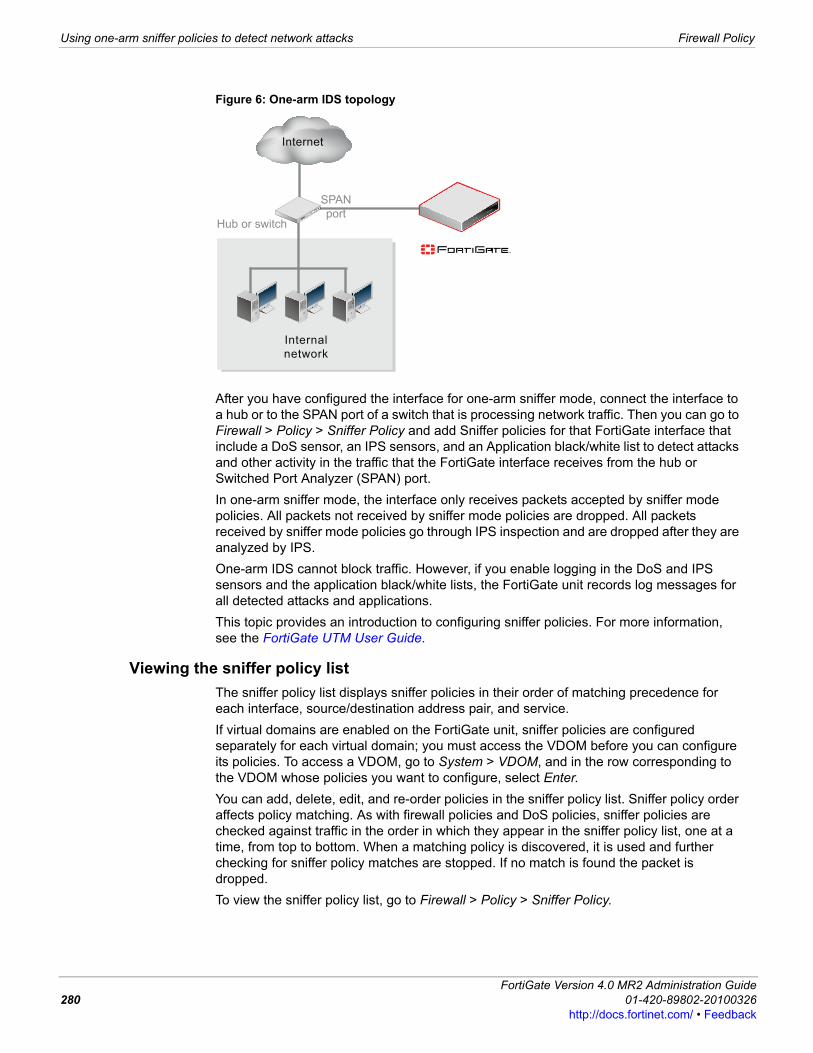
Using one-arm sniffer policies to detect network attacks Firewall Policy
Figure 6: One-arm IDS topology
After you have configured the interface for one-arm sniffer mode, connect the interface to a hub or to the SPAN port of a switch that is processing network traffic. Then you can go to Firewall > Policy > Sniffer Policy and add Sniffer policies for that FortiGate interface that include a DoS sensor, an IPS sensors, and an Application black/white list to detect attacks and other activity in the traffic that the FortiGate interface receives from the hub or Switched Port Analyzer (SPAN) port.In one-arm sniffer mode, the interface only receives packets accepted by sniffer mode policies. All packets not received by sniffer mode policies are dropped. All packets received by sniffer mode policies go through IPS inspection and are dropped after they are analyzed by IPS.One-arm IDS cannot block traffic. However, if you enable logging in the DoS and IPS sensors and the application black/white lists, the FortiGate unit records log messages for all detected attacks and applications.This topic provides an introduction to configuring sniffer policies. For more information, see the FortiGate UTM User Guide.
Viewing the sniffer policy listThe sniffer policy list displays sniffer policies in their order of matching precedence for each interface, source/destination address pair, and service.If virtual domains are enabled on the FortiGate unit, sniffer policies are configured separately for each virtual domain; you must access the VDOM before you can configure its policies. To access a VDOM, go to System > VDOM, and in the row corresponding to the VDOM whose policies you want to configure, select Enter.You can add, delete, edit, and re-order policies in the sniffer policy list. Sniffer policy order affects policy matching. As with firewall policies and DoS policies, sniffer policies are checked against traffic in the order in which they appear in the sniffer policy list, one at a time, from top to bottom. When a matching policy is discovered, it is used and further checking for sniffer policy matches are stopped. If no match is found the packet is dropped.To view the sniffer policy list, go to Firewall > Policy > Sniffer Policy.
Hub or switch
SPAN
port
Internet
Internal
network
FortiGate Version 4.0 MR2 Administration Guide280 01-420-89802-20100326
http://docs.fortinet.com/ • Feedback
Firewall Policy Using one-arm sniffer policies to detect network attacks
F0h
Configuring sniffer policiesUse the sniffer policy configuration to specify the interface, a source address, a destination address, and a service. All of the specified attributes must match network traffic to trigger the policy.You can also use the config firewall sinff-interface-policy CLI command to add sniffer policies from the CLI. For more information, see the FortiGate CLI Reference.You can use the config firewall sniff-interface-policy6 command to add IPv6 sniffer policies. For more information about FortiGate IPv6 support, see “FortiGate IPv6 support” on page 185.
Sniffer Policy pageLists each individual sniffer policy that you created. On this page, you can edit, delete and create a new sniffer policy. You can also move a policy or insert a new policy on the page.
Create New Add new a sniffer policy. Select the down arrow beside Create New to add a new section to the list to visually group the policies.
Column Settings Customize the table view. You can select the columns to hide or display and specify the column displaying order in the table. See “Using column settings to control the columns displayed” on page 35.
Section View Select to display firewall policies organized by interface.
Global View Select to list all firewall policies in order according to a sequence number.
Filter icons Edit column filters to filter or sort the policy list according to the criteria you specify. For more information, see “Adding filters to web-based manager lists” on page 33.
ID A unique identifier for each policy. Policies are numbered in the order they are created.
Source The source address or address group to which the policy applies. For more information, see “Firewall Address” on page 293.
Destination The destination address or address group to which the policy applies. For more information, see “Firewall Address” on page 293.
Service The service to which the policy applies. For more information, see “Firewall Service” on page 299.
DoS The DoS sensor selected in this policy.
Sensor The IPS sensor selected in this policy.
Application Black/White List
The Application Black/White List selected in this policy.
Status When selected, the DoS policy is enabled. Clear the check box to disable the policy. See “Enabling and disabling policies” on page 264.
Delete Delete the policy from the list.
Edit Edit the policy.
Insert Policy Before Add a new policy above the corresponding policy (the New Policy screen appears).
Move To Move the corresponding policy before or after another policy in the list.
New Policy pageProvides settings for configuring a new sniffer policy. When you select Create New on the Sniffer Policy page, you are automatically redirected to this page.
Source Interface/Zone The interface or zone to be monitored.
Source Address Select an address, address range, or address group to limit traffic monitoring to network traffic sent from the specified address or range. Select Multiple to include multiple addresses or ranges. You can also select Create New to add a new address or address group.
ortiGate Version 4.0 MR2 Administration Guide1-420-89802-20100326 281ttp://docs.fortinet.com/ • Feedback
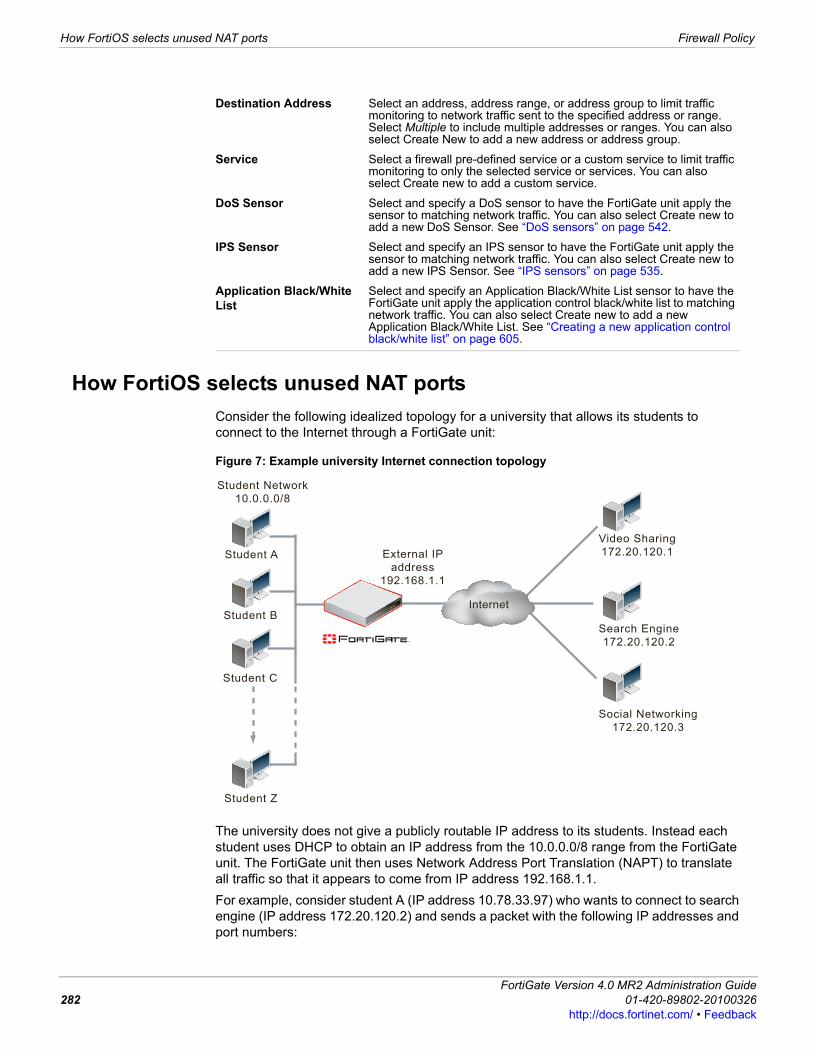
How FortiOS selects unused NAT ports Firewall Policy
How FortiOS selects unused NAT portsConsider the following idealized topology for a university that allows its students to connect to the Internet through a FortiGate unit:
Figure 7: Example university Internet connection topology
The university does not give a publicly routable IP address to its students. Instead each student uses DHCP to obtain an IP address from the 10.0.0.0/8 range from the FortiGate unit. The FortiGate unit then uses Network Address Port Translation (NAPT) to translate all traffic so that it appears to come from IP address 192.168.1.1.For example, consider student A (IP address 10.78.33.97) who wants to connect to search engine (IP address 172.20.120.2) and sends a packet with the following IP addresses and port numbers:
Destination Address Select an address, address range, or address group to limit traffic monitoring to network traffic sent to the specified address or range. Select Multiple to include multiple addresses or ranges. You can also select Create New to add a new address or address group.
Service Select a firewall pre-defined service or a custom service to limit traffic monitoring to only the selected service or services. You can also select Create new to add a custom service.
DoS Sensor Select and specify a DoS sensor to have the FortiGate unit apply the sensor to matching network traffic. You can also select Create new to add a new DoS Sensor. See “DoS sensors” on page 542.
IPS Sensor Select and specify an IPS sensor to have the FortiGate unit apply the sensor to matching network traffic. You can also select Create new to add a new IPS Sensor. See “IPS sensors” on page 535.
Application Black/White List
Select and specify an Application Black/White List sensor to have the FortiGate unit apply the application control black/white list to matching network traffic. You can also select Create new to add a new Application Black/White List. See “Creating a new application control black/white list” on page 605.
Student Network
10.0.0.0/8
Student A
Student B
Student C
Student Z
Video Sharing
172.20.120.1
Search Engine
172.20.120.2
Social Networking
172.20.120.3
Internet
External IP
address
192.168.1.1
FortiGate Version 4.0 MR2 Administration Guide282 01-420-89802-20100326
http://docs.fortinet.com/ • Feedback
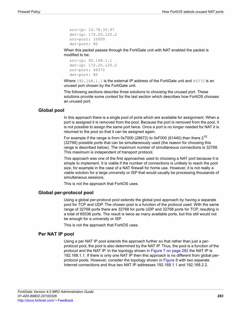
Firewall Policy How FortiOS selects unused NAT ports
F0h
src-ip: 10.78.33.97dst-ip: 172.20.120.2src-port: 10000dst-port: 80
When this packet passes through the FortiGate unit with NAT enabled the packet is modified to be:
src-ip: 92.168.1.1dst-ip: 172.20.120.2src-port: 46372dst-port: 80
Where 192.168.1.1 is the external IP address of the FortiGate unit and 46372 is an unused port chosen by the FortiGate unit.The following sections describe three solutions to choosing the unused port. These solutions provide some context for the last section which describes how FortiOS chooses an unused port.
Global poolIn this approach there is a single pool of ports which are available for assignment. When a port is assigned it is removed from the pool. Because the port is removed from the pool, it is not possible to assign the same port twice. Once a port is no longer needed for NAT it is returned to the pool so that it can be assigned again.For example if the range is from 0x7000 (28672) to 0xF000 (61440) then there 215 (32768) possible ports that can be simultaneously used (the reason for choosing this range is described below). The maximum number of simultaneous connections is 32768. This maximum is independent of transport protocol.This approach was one of the first approaches used to choosing a NAT port because it is simple to implement. It is viable if the number of connections is unlikely to reach the pool size, for example in the case of a NAT firewall for home use. However, it is not really a viable solution for a large university or ISP that would usually be processing thousands of simultaneous sessions.This is not the approach that FortiOS uses.
Global per-protocol poolUsing a global per-protocol pool extends the global pool approach by having a separate pool for TCP and UDP. The chosen pool is a function of the protocol used. With the same range of 32768 ports there are 32768 for ports UDP and 32768 ports for TCP, resulting in a total of 65536 ports. The result is twice as many available ports, but this still would not be enough for a university or ISP.This is not the approach that FortiOS uses.
Per NAT IP poolUsing a per NAT IP pool extends the approach further so that rather than just a per-protocol pool, the pool is also determined by the NAT IP. Thus, the pool is a function of the protocol and the NAT IP. In the topology shown in Figure 7 on page 282 the NAT IP is 192.168.1.1. If there is only one NAT IP then this approach is no different from global per-protocol pools. However, consider the topology shown in Figure 8 with two separate Internet connections and thus two NAT IP addresses 192.168.1.1 and 192.168.2.2.
ortiGate Version 4.0 MR2 Administration Guide1-420-89802-20100326 283ttp://docs.fortinet.com/ • Feedback
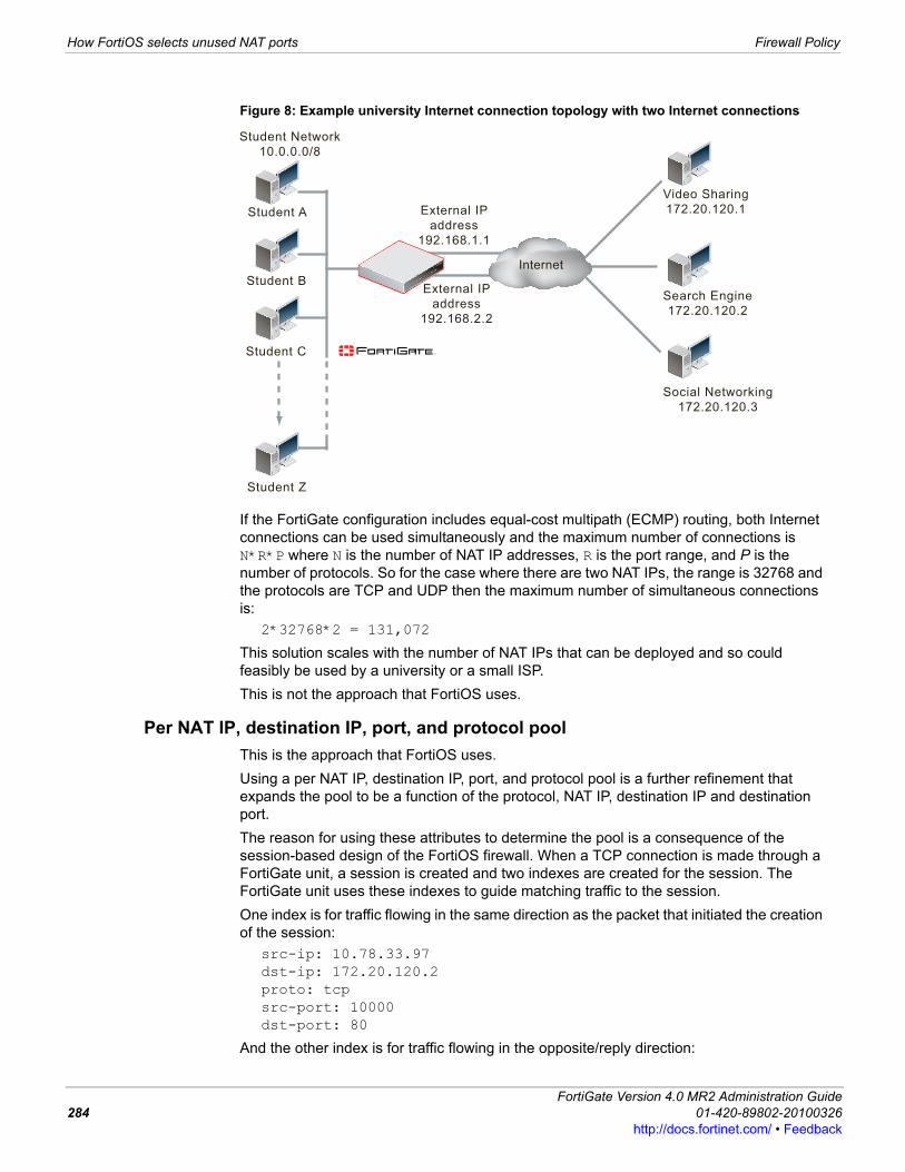
How FortiOS selects unused NAT ports Firewall Policy
Figure 8: Example university Internet connection topology with two Internet connections
If the FortiGate configuration includes equal-cost multipath (ECMP) routing, both Internet connections can be used simultaneously and the maximum number of connections is N*R*P where N is the number of NAT IP addresses, R is the port range, and P is the number of protocols. So for the case where there are two NAT IPs, the range is 32768 and the protocols are TCP and UDP then the maximum number of simultaneous connections is:
2*32768*2 = 131,072
This solution scales with the number of NAT IPs that can be deployed and so could feasibly be used by a university or a small ISP.This is not the approach that FortiOS uses.
Per NAT IP, destination IP, port, and protocol poolThis is the approach that FortiOS uses.Using a per NAT IP, destination IP, port, and protocol pool is a further refinement that expands the pool to be a function of the protocol, NAT IP, destination IP and destination port.The reason for using these attributes to determine the pool is a consequence of the session-based design of the FortiOS firewall. When a TCP connection is made through a FortiGate unit, a session is created and two indexes are created for the session. The FortiGate unit uses these indexes to guide matching traffic to the session. One index is for traffic flowing in the same direction as the packet that initiated the creation of the session:
src-ip: 10.78.33.97dst-ip: 172.20.120.2proto: tcpsrc-port: 10000dst-port: 80
And the other index is for traffic flowing in the opposite/reply direction:
Student Network
10.0.0.0/8
Student A
Student B
Student C
Student Z
Video Sharing
172.20.120.1
Search Engine
172.20.120.2
Social Networking
172.20.120.3
Internet
External IP
address
192.168.1.1
External IP
address
192.168.2.2
FortiGate Version 4.0 MR2 Administration Guide284 01-420-89802-20100326
http://docs.fortinet.com/ • Feedback
Firewall Policy How FortiOS selects unused NAT ports
F0h
src-ip: 172.20.120.2dst-ip: 192.168.1.1proto: tcpsrc-port: 80dst-port: 46372
Where 46372 is the chosen NAT port. In both cases when traffic matches either of these indexes the session that the traffic belongs to can be uniquely identified.Using a per NAT IP, destination IP, port, and protocol pool, when choosing the NAT port FortiOS only has to ensure that the chosen port combined with the other four attributes are unique to uniquely identify the session. So for example, if student A simultaneously makes a connection to the search engine (destination IP address 172.20.120.2) on port 443 this would create another session and the index in the reply direction would be:
src-ip: 172.20.120.2dst-ip: 192.168.1.1proto: tcpsrc-port: 443dst-port: NP
The value of NP can be any value as long as the five values together are unique. For example, FortiOS could choose 46372 again:
src-ip: 172.20.120.2dst-ip: 192.168.1.1proto: tcpsrc-port: 443dst-port: 46372
This is acceptable because:src-ip: 172.20.120.2dst-ip: 192.168.1.1proto: tcpsrc-port: 80dst-port: 46372
andsrc-ip: 172.20.120.2dst-ip: 192.168.1.1proto: tcpsrc-port: 443dst-port: 46372
have different src-port values.The result of using the per NAT IP, destination IP, port, and protocol pool approach is that a pool of 32768 ports are available for each unique combination of src-ip, dst-ip, proto and src-port.The maximum number of simultaneous connections that can be supported is N*R*P*D*Dp where N is the number of NAT IP addresses, R is the port range, P is the number of protocols, D is the number of unique destination IP addresses and Dp the number of unique destination ports. Considering the large number of destination IP addresses available, the number of simultaneous connections that can be supported is very large. To get an idea of how large, for one destination IP address and one NAT IP address the calculation would be N=1, R=32, 768, P=2, D=1 and Dp=32,768:
1 * 32,768 * 2 * 1 * 32,768 = 2,147,483,648.
ortiGate Version 4.0 MR2 Administration Guide1-420-89802-20100326 285ttp://docs.fortinet.com/ • Feedback
Firewall policy examples Firewall Policy
A problem with this calculation is that not all 32,768 possible destination ports are used. In fact for many organizations, must Internet traffic is web traffic using destination port 80 and all using the TCP protocol. So the pool size limit for web traffic to one destination IP address from one NAT IP address using the TCP protocol would be N=1, R=32, 768, P=1, D=1 and Dp=1:
1* 32,768 * 1 * 1 * 1 = 32,768
Using the topology in Figure 7 on page 282, for students simultaneously connecting to the search engine, the social networking and the video sharing sites on TCP port 80 then assuming each site uses one IP address a maximum of 32,768 simultaneous connections are allowed to each site or 32,768 * 3 = 98,304 connections in total.Many large public web sites may use round-robin DNS to rotate through at least four IP addresses. If the search engine and the video sharing site did this with an even balance of IP usage the result would be a maximum of 4 * 32,768 = 131,072 connections to the search engine, 131,072 connections to the video sharing site and 32,768 connections to the social networking site for a total of 294,912 different connections supported by the single FortiGate unit with one NAT IP and for a total of 9 destination IP addresses and one destination port.
Firewall policy examplesFortiGate units are capable of meeting various network requirements from home use to SOHO, large enterprises and ISPs. The following two scenarios demonstrate practical applications of firewall policies in the SOHO and large enterprise environments.This topic describes the following:• Example one: SOHO-sized business• Example two: Enterprise-sized business• Viewing the firewall policy list• Configuring firewall policies
Example one: SOHO-sized businessCompany A is a small software company performing development and providing customer support. In addition to their internal network of 15 computers, they also have several employees who work from home all or some of the time.With their current network topography, all 15 of the internal computers are behind a router and must go to an external source to access the IPS mail and web servers. All home-based employees access the router through open/non-secured connections.
FortiGate Version 4.0 MR2 Administration Guide286 01-420-89802-20100326
http://docs.fortinet.com/ • Feedback

Firewall Policy Firewall policy examples
F0h
Figure 9: Example SOHO network before FortiGate installation
Company A requires secure connections for home-based workers. Like many companies, they rely heavily on email and Internet access to conduct business. They want a comprehensive security solution to detect and prevent network attacks, block viruses, and decrease spam. They want to apply different protection settings for different departments. They also want to integrate web and email servers into the security solution.To deal with their first requirement, Company A configures specific policies for each home-based worker to ensure secure communication between the home-based worker and the internal network.1 Go to Firewall > Policy.2 Select Create New and enter or select the following settings for Home_User_1:
Interface / Zone Source: internal Destination: wan1
Address Source: CompanyA_Network
Destination: Home_User_1
Schedule Always
Service ANY
Action IPSEC
VPN Tunnel Home1
Allow Inbound yes
Allow outbound yes
Inbound NAT yes
Outbound NAT no
Protection Profile Select the check mark and select standard_profile
Home-based Workers
(no secure connection)IPS Mail
ServerISP Web
Server
Internet
172.16.10.3
192.168.100.1
Internal Network
Finance
Department
Help
DeskEngineering
Department
ortiGate Version 4.0 MR2 Administration Guide1-420-89802-20100326 287ttp://docs.fortinet.com/ • Feedback
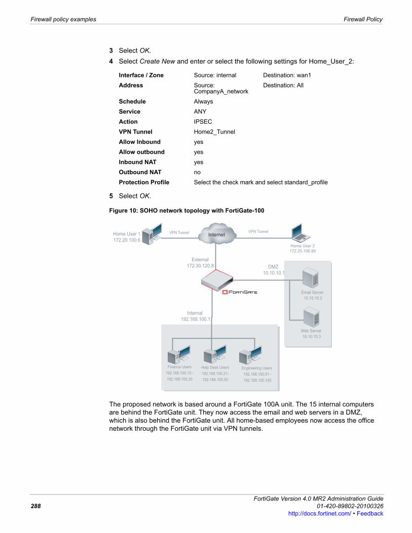
Firewall policy examples Firewall Policy
3 Select OK.4 Select Create New and enter or select the following settings for Home_User_2:
5 Select OK.
Figure 10: SOHO network topology with FortiGate-100
The proposed network is based around a FortiGate 100A unit. The 15 internal computers are behind the FortiGate unit. They now access the email and web servers in a DMZ, which is also behind the FortiGate unit. All home-based employees now access the office network through the FortiGate unit via VPN tunnels.
Interface / Zone Source: internal Destination: wan1
Address Source: CompanyA_network
Destination: All
Schedule Always
Service ANY
Action IPSEC
VPN Tunnel Home2_Tunnel
Allow Inbound yes
Allow outbound yes
Inbound NAT yes
Outbound NAT no
Protection Profile Select the check mark and select standard_profile
Internet
Finance Users
192.168.100.10 -
192.168.100.20
Web Server
10.10.10.3
Email Server
10.10.10.2
Home User 2
172.25.106.99
Home User 1
172.20.100.6
Help Desk Users
192.168.100.21-
192.168.100.50
Engineering Users
192.168.100.51 -
192.168.100.100
External
172.30.120.8
Internal
192.168.100.1
DMZ
10.10.10.1
VPN Tunnel VPN Tunnel
FortiGate Version 4.0 MR2 Administration Guide288 01-420-89802-20100326
http://docs.fortinet.com/ • Feedback

Firewall Policy Firewall policy examples
F0h
Example two: Enterprise-sized businessLocated in a large city, the library system is anchored by a main downtown location serving most of the population, with more than a dozen branches spread throughout the city. Each branch is wired to the Internet but none are linked with each other by dedicated connections.The current network topography at the main location consists of three user groups. The main branch staff and public terminals access the servers in the DMZ behind the firewall. The catalog access terminals directly access the catalog server without first going through the firewall.The topography at the branch office has all three users accessing the servers at the main branch through non-secured internet connections.
Figure 11: The library system’s current network topology
The library must be able to set different access levels for patrons and staff members.The first firewall policy for main office staff members allows full access to the Internet at all times. A second policy will allow direct access to the DMZ for staff members. A second pair of policies is required to allow branch staff members the same access.The staff firewall policies will all use a protection profile configured specifically for staff access. Enabled features include virus scanning, email filtering, IPS, and blocking of all P2P traffic. FortiGuard web filtering is also used to block advertising, malware, and spyware sites.A few users may need special web and catalog server access to update information on those servers, depending on how they are configured. Special access can be allowed based on IP address or user.
Public terminals
Branch Staff
Catalog access terminals
(non-Fortinet) Firewall
Internet
(non-Fortinet) Firewall
Main branch staff
and administration
Public terminals
Catalog access terminals
Catalog server Mail Server Web Server
Branch configuration (only one branch shown)
Main location configuration
ortiGate Version 4.0 MR2 Administration Guide1-420-89802-20100326 289ttp://docs.fortinet.com/ • Feedback
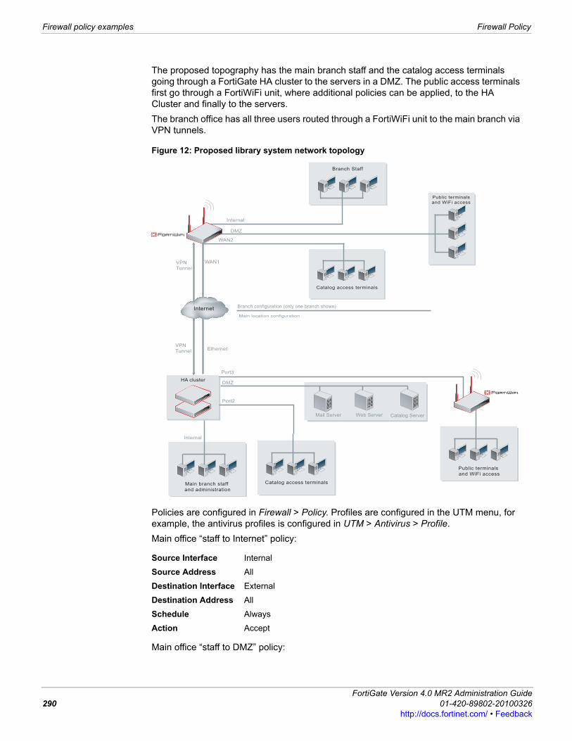
Firewall policy examples Firewall Policy
The proposed topography has the main branch staff and the catalog access terminals going through a FortiGate HA cluster to the servers in a DMZ. The public access terminals first go through a FortiWiFi unit, where additional policies can be applied, to the HA Cluster and finally to the servers.The branch office has all three users routed through a FortiWiFi unit to the main branch via VPN tunnels.
Figure 12: Proposed library system network topology
Policies are configured in Firewall > Policy. Profiles are configured in the UTM menu, for example, the antivirus profiles is configured in UTM > Antivirus > Profile. Main office “staff to Internet” policy:
Main office “staff to DMZ” policy:
Source Interface Internal
Source Address All
Destination Interface External
Destination Address All
Schedule Always
Action Accept
Branch Staff
Public terminals
and WiFi access
Catalog access terminals
Internal
DMZ
WAN2
VPN
Tunnel
Internet
VPN
Tunnel
WAN1
Ethernet
Main branch staff
and administration
Catalog access terminals
HA cluster
Catalog ServerWeb ServerMail Server
Port2
Internal
DMZ
Public terminals
and WiFi access
Port3
Branch configuration (only one branch shown)
Main location configuration
FortiGate Version 4.0 MR2 Administration Guide290 01-420-89802-20100326
http://docs.fortinet.com/ • Feedback

Firewall Policy Firewall policy examples
F0h
Branches “staff to Internet” policy:
Branches “staff to DMZ” policy:
For more information about these examples, see:• SOHO and SMB Configuration Example Guide • FortiGate Enterprise Configuration Example
Source Interface Internal
Source Address All
Destination Interface DMZ
Destination Address Servers
Schedule Always
Action Accept
Source Interface Branches
Source Address Branch Staff
Destination Interface External
Destination Address All
Schedule Always
Action Accept
Source Interface Branches
Source Address Branch Staff
Destination Interface DMZ
Destination Address Servers
Schedule Always
Action Accept
ortiGate Version 4.0 MR2 Administration Guide1-420-89802-20100326 291ttp://docs.fortinet.com/ • Feedback
Firewall policy examples Firewall Policy
FortiGate Version 4.0 MR2 Administration Guide292 01-420-89802-20100326
http://docs.fortinet.com/ • Feedback

Firewall Address About firewall addresses
Firewall AddressFirewall addresses and address groups define network addresses that you can use when configuring firewall policies’ source and destination address fields. The FortiGate unit compares the IP addresses contained in packet headers with firewall policy source and destination addresses to determine if the firewall policy matches the traffic. You can add IPv4 addresses and address ranges, IPv6 addresses, and fully qualified domain names (FQDNs).You can organize related addresses into address groups and related IPv6 addresses into IPv6 address groups to simplify your firewall policy lists.If you enable virtual domains (VDOMs) on the FortiGate unit, firewall addresses are configured separately for each virtual domain, and you must first enter the virtual domain to configure its firewall addresses. For more information, see “Using virtual domains” on page 73.The following topics are included in this section:• About firewall addresses• About IPv6 firewall addresses• Viewing the firewall address list• Configuring addresses• Viewing the address group list• Configuring address groups
About firewall addresses
This section describes the options for adding firewall addresses. These are IPv4 addresses, address ranges, or fully qualified domain names (FQDNs). You can also add IPv6 addresses. See “About IPv6 firewall addresses” on page 294.A firewall address can contain one or more network addresses. Network addresses can be represented by an IP address with a netmask, an IP address range, or a fully qualified domain name (FQDN).When representing hosts by an IP address with a netmask, the IP address can represent one or more hosts. For example, a firewall address can be:• a single computer, such as 192.45.46.45• a subnetwork, such as 192.168.1.0 for a class C subnet• 0.0.0.0, which matches any IP addressThe netmask corresponds to the subnet class of the address being added, and can be represented in either dotted decimal or CIDR format. The FortiGate unit automatically converts CIDR formatted netmasks to dotted decimal format. Example formats:
Caution: Be cautious if employing FQDN firewall addresses. Using a fully qualified domain name in a firewall policy, while convenient, does present some security risks because policy matching then relies on a trusted DNS server. If the DNS server should ever be compromised, firewall policies requiring domain name resolution may no longer function properly.
FortiGate Version 4.0 MR2 Administration Guide01-420-89802-20100326 293http://docs.fortinet.com/ • Feedback
About IPv6 firewall addresses Firewall Address
294
• netmask for a single computer: 255.255.255.255, or /32• netmask for a class A subnet: 255.0.0.0, or /8• netmask for a class B subnet: 255.255.0.0, or /16• netmask for a class C subnet: 255.255.255.0, or /24• netmask including all IP addresses: 0.0.0.0Valid IP address and netmask formats include:• x.x.x.x/x.x.x.x, such as 192.168.1.0/255.255.255.0• x.x.x.x/x, such as 192.168.1.0/24
When representing hosts by an IP Range, the range indicates hosts with continuous IP addresses in a subnet, such as 192.168.1.[2-10], or 192.168.1.* to indicate the complete range of hosts on that subnet. Valid IP Range formats include:• x.x.x.x-x.x.x.x, such as 192.168.110.100-192.168.110.120• x.x.x.[x-x], such as 192.168.110.[100-120]• x.x.x.*, such as 192.168.110.*When representing hosts by a FQDN, the domain name can be a subdomain, such as mail.example.com. A single FQDN firewall address may be used to apply a firewall policy to multiple hosts, as in load balancing and high availability (HA) configurations. FortiGate units automatically resolve and maintain a record of all addresses to which the FQDN resolves. Valid FQDN formats include:• <host_name>.<second_level_domain_name>.<top_level_domain_name>, such as
mail.example.com
• <host_name>.<top_level_domain_name>Using FQDN addresses in firewall policies has the advantage of causing the FortiGate unit to keep track of DNS TTLs and adapt as records change. This feature can reduce maintenance requirements for changing firewall addresses for dynamic IP addresses. This also means that you can create firewall policies for networks configured with dynamic addresses using DHCP.
About IPv6 firewall addressesBy default, IPv6 firewall addresses can be configured only from the CLI. To enable configuring IPv6 settings on the web-based manager, see “Settings” on page 183.An Ipv6 firewall address can contain one IPv6 address or an IPv6 address and subnet. You cannot add IPv6 address ranges.Example IPv6 firewall address:
3ffe:ffff:1011:f101:0210:a4ff:fee3:9566/128
The FortiGate units adds the /128 netmask.Example IPv6 firewall address for a subnet:
2001:470:1f0e:162::/64
The IPv6 address field is restricted to around 34 characters so you cannot add full IPv6 addresses and netmasks. Instead you should use the short form netmask shown in the examples.
Note: An IP address 0.0.0.0 with netmask 255.255.255.255 is not a valid firewall address.
FortiGate Version 4.0 MR2 Administration Guide01-420-89802-20100326
http://docs.fortinet.com/ • Feedback
Firewall Address Viewing the firewall address list
You cannot assign IPv6 addresses to a FortiGate interface.
Viewing the firewall address listFirewall addresses in the list are grouped by type: IP/Netmask, FQDN, or IPv6. FortiGate unit default configurations include the all address, which represents any IPv4 IP address on any network.To view the address list, go to Firewall > Address > Address.
Configuring addresses
To add a firewall address go to Firewall > Address > Address and select Create New. You can add a static IP address, an IP address range, or a FQDN.If IPv6 Support is enabled, to add an IPv6 firewall address, go to Firewall > Address > Address, select the down arrow beside Create New, and then select IPv6 Address.
Address pageLists each individual IP address group. On this page, you can edit, delete or create a new IP address group.
Create New Add a firewall address. When you select Create New, you are automatically redirected to the New Address page. If IPv6 Support is enabled you can select the down arrow in the Create New button and select IPv6 Address, to add an IPv6 firewall address. To enable IPv6 support on the web-based manager, see “Settings” on page 183.
Name The name of the firewall address.
Address / FQDN The IP address and mask, IP address range, or fully qualified domain name.
Interface The interface, zone, or virtual domain (VDOM) to which you bind the IP address.
IP/Netmask The list of IPv4 firewall addresses and address ranges.
FQDN The list of fully qualified domain name firewall addresses.
IPv6 The list of IPv6 firewall addresses.
Delete Select to remove the address. The Delete icon appears only if a firewall policy or address group is not currently using the address.
Edit Select to edit the address.
Caution: Be cautious when FQDN firewall addresses. Using a fully qualified domain name in a firewall policy, while convenient, does present some security risks, because policy matching then relies on a trusted DNS server. Should the DNS server be compromised, firewall policies requiring domain name resolution may no longer function properly.
Tip: You can also add firewall addresses when configuring a firewall policy: Go to Firewall > Policy > Policy , select the appropriate policy tab, and then select Create New. From the Source Address list, select Address > Create New.
New Address pageProvides settings for configuring an IP address group, which is made up of an IP address range.
Address Name Enter a name to identify the firewall address. Addresses, address groups, and virtual IPs must have unique names.
Type Select the type of address: Subnet/IP Range or FQDN. You can enter either an IP range or an IP address with subnet mask.
Subnet / IP Range
Enter the firewall IP address, followed by a forward slash (/), then subnet mask, or enter an IP address range separated by a hyphen. See “About firewall addresses” on page 293.
FortiGate Version 4.0 MR2 Administration Guide01-420-89802-20100326 295http://docs.fortinet.com/ • Feedback
Viewing the address group list Firewall Address
296
Viewing the address group listYou can organize multiple firewall addresses into an address group to simplify your firewall policy list. For example, instead of having five identical policies for five different but related firewall addresses, you might combine the five addresses into a single address group, which is used by a single firewall policy.To view the address group list, go to Firewall > Address > Group.
Configuring address groupsBecause firewall policies require addresses with homogenous network interfaces, address groups should contain only addresses bound to the same network interface, or to Any — addresses whose selected interface is Any are bound to a network interface during creation of a firewall policy, rather than during creation of the firewall address. For example, if address A1 is associated with port1, and address A2 is associated with port2, they cannot be grouped. However, if A1 and A2 have an interface of Any, they can be grouped, even if the addresses involve different networks.You cannot mix IPv4 firewall addresses and IPv6 firewall addresses in the same address group.To organize addresses into an address group go to Firewall > Address > Group and select Create New.If IPv6 Support is enabled, to add an IPv6 firewall address group, Firewall > Address > Group, select the down arrow beside Create New, and then select IPv6 Address Group.
Interface Select the interface, zone, or virtual domain (VDOM) link to which you want to bind the IP address. Select Any if you want to bind the IP address with the interface/zone when you create a firewall policy.
IPv6 Address Enter the firewall IPv6 address, followed by a forward slash (/), then subnet mask. See “About IPv6 firewall addresses” on page 294.
Group pageLists each individual address group that you created. On this page, you can edit, delete or create a new address group.
Create New Add an address group. When you select Create New, you are automatically redirected to the New Address Group page. If IPv6 Support is enabled you can select the down arrow in the Create New button and select IPv6 Address Group, to add an IPv6 firewall address. To enable IPv6 support on the web-based manager, see “Settings” on page 183.
Group Name The name of the address group.
Members The addresses in the address group.
Address Group The list of firewall IPv4 address groups.
IPv6 Address Group The list of firewall IPv6 address groups.
Delete Select to remove the address group. The Delete icon appears only if the address group is not currently being used by a firewall policy.
Edit Select to edit the address group.
Tip: You can also create firewall address groups when configuring a firewall policy: Go to Firewall > Policy > Policy, select the appropriate policy tab, and then select Create New. From the Source Address list, select Address Group > Create New.
FortiGate Version 4.0 MR2 Administration Guide01-420-89802-20100326
http://docs.fortinet.com/ • Feedback
Firewall Address Configuring address groups
New Address Group pageProvides settings for defining the IP address that will be members of the IP address group.
Group Name Enter a name to identify the address group. Addresses, address groups, and virtual IPs must have unique names.
Available Addresses
The list of all IPv4 or IPv6 firewall addresses. Use the arrows to move selected addresses between the lists of available and member addresses. You cannot add IPv4 and IPv6 firewall addresses to the same address group. If you are adding an IPv4 firewall address group only the IPv4 addresses and FQDN addresses appear. If you are added an IPv6 firewall address group, only the IPv6 addresses appear.
Members The list of addresses included in the address group. Use the arrows to move selected addresses between the lists of available and member addresses.
FortiGate Version 4.0 MR2 Administration Guide01-420-89802-20100326 297http://docs.fortinet.com/ • Feedback
Configuring address groups Firewall Address
298
FortiGate Version 4.0 MR2 Administration Guide01-420-89802-20100326http://docs.fortinet.com/ • Feedback
Firewall Service Viewing the predefined service list
Firewall ServiceFirewall services define one or more protocols and port numbers associated with each service. Firewall policies use service definitions to match session types.You can organize related services into service groups to simplify your firewall policy list.If you enable virtual domains (VDOMs) on the FortiGate unit, you must configure firewall services separately for each virtual domain. For more information, see “Using virtual domains” on page 73.The following topics are included in this section:• Viewing the predefined service list• Configuring custom services• Configuring custom service groups
Viewing the predefined service listMany well-known traffic types have been predefined in firewall services. These predefined services are defaults, and cannot be edited or removed. However, if you require different services, you can create custom services. For more information, see “Configuring custom services” on page 304.To view the predefined service list, go to Firewall > Service > Predefined. Table 47 lists the FortiGate firewall predefined services.
Predefined pageLists all the predefined services that are available. Table 47 lists and explains each firewall predefined service that is available on the FortiGate unit.
Name The name of the predefined service.
Detail The protocol (TCP, UDP, IP, ICMP) and port number or numbers of the predefined service.
Table 47: Predefined services
Service name Description IP Protocol PortAFS3 Advanced File Security Encrypted File, version 3, of
the AFS distributed file system protocol.TCP 7000-7009
UDP 7000-7009
AH Authentication Header. AH provides source host authentication and data integrity, but not secrecy. This protocol is used for authentication by IPSec remote gateways set to aggressive mode.
51
ANY Matches connections using any protocol over IP. all all
AOL America Online Instant Message protocol. TCP 5190-5194
BGP Border Gateway Protocol. BGP is an interior/exterior routing protocol.
TCP 179
CVSPSERVER Concurrent Versions System Proxy Server.CSSPServer is very good for providing anonymous CVS access to a repository.
TCP 2401
UDP 2401
FortiGate Version 4.0 MR2 Administration Guide01-420-89802-20100326 299http://docs.fortinet.com/ • Feedback
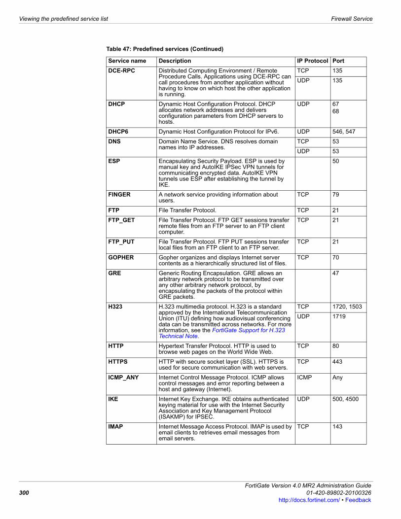
Viewing the predefined service list Firewall Service
300
DCE-RPC Distributed Computing Environment / Remote Procedure Calls. Applications using DCE-RPC can call procedures from another application without having to know on which host the other application is running.
TCP 135
UDP 135
DHCP Dynamic Host Configuration Protocol. DHCP allocates network addresses and delivers configuration parameters from DHCP servers to hosts.
UDP 6768
DHCP6 Dynamic Host Configuration Protocol for IPv6. UDP 546, 547
DNS Domain Name Service. DNS resolves domain names into IP addresses.
TCP 53
UDP 53
ESP Encapsulating Security Payload. ESP is used by manual key and AutoIKE IPSec VPN tunnels for communicating encrypted data. AutoIKE VPN tunnels use ESP after establishing the tunnel by IKE.
50
FINGER A network service providing information about users.
TCP 79
FTP File Transfer Protocol. TCP 21
FTP_GET File Transfer Protocol. FTP GET sessions transfer remote files from an FTP server to an FTP client computer.
TCP 21
FTP_PUT File Transfer Protocol. FTP PUT sessions transfer local files from an FTP client to an FTP server.
TCP 21
GOPHER Gopher organizes and displays Internet server contents as a hierarchically structured list of files.
TCP 70
GRE Generic Routing Encapsulation. GRE allows an arbitrary network protocol to be transmitted over any other arbitrary network protocol, by encapsulating the packets of the protocol within GRE packets.
47
H323 H.323 multimedia protocol. H.323 is a standard approved by the International Telecommunication Union (ITU) defining how audiovisual conferencing data can be transmitted across networks. For more information, see the FortiGate Support for H.323 Technical Note.
TCP 1720, 1503
UDP 1719
HTTP Hypertext Transfer Protocol. HTTP is used to browse web pages on the World Wide Web.
TCP 80
HTTPS HTTP with secure socket layer (SSL). HTTPS is used for secure communication with web servers.
TCP 443
ICMP_ANY Internet Control Message Protocol. ICMP allows control messages and error reporting between a host and gateway (Internet).
ICMP Any
IKE Internet Key Exchange. IKE obtains authenticated keying material for use with the Internet Security Association and Key Management Protocol (ISAKMP) for IPSEC.
UDP 500, 4500
IMAP Internet Message Access Protocol. IMAP is used by email clients to retrieves email messages from email servers.
TCP 143
Table 47: Predefined services (Continued)
Service name Description IP Protocol Port
FortiGate Version 4.0 MR2 Administration Guide01-420-89802-20100326
http://docs.fortinet.com/ • Feedback

Firewall Service Viewing the predefined service list
IMAPS IMAP with SSL. IMAPS is used for secure IMAP communication between email clients and servers. IMAPS is only available on FortiGate units that support SSL content scanning and inspection. For more information, see the UTM chapter of the FortiOS Handbook.
TCP 993
INFO_ADDRESS ICMP information request messages. ICMP 17
INFO_REQUEST ICMP address mask request messages. ICMP 15
IRC Internet Relay Chat. IRC allows users to join chat channels.
TCP 6660-6669
Internet-Locator-Service
Internet Locator Service. ILS includes LDAP, User Locator Service, and LDAP over TLS/SSL.
TCP 389
L2TP Layer 2 Tunneling Protocol. L2TP is a PPP-based tunnel protocol for remote access.
TCP 1701
UDP 1701
LDAP Lightweight Directory Access Protocol. LDAP is used to access information directories.
TCP 389
MGCP Media Gateway Control Protocol. MGCP is used by call agents and media gateways in distributed Voice over IP (VoIP) systems.
UDP 2427, 2727
MS-SQL Microsoft SQL Server is a relational database management system (RDBMS) produced by Microsoft. Its primary query languages are MS-SQL and T-SQL.
TCP 1433, 1434
MYSQL MySQL is a relational database management system (RDBMS) which runs as a server providing multi-user access to a number of databases.
TCP 3306
NFS Network File System. NFS allows network users to mount shared files.
TCP 111, 2049
UDP 111, 2049
NNTP Network News Transport Protocol. NNTP is used to post, distribute, and retrieve Usenet messages.
TCP 119
NTP Network Time Protocol. NTP synchronizes a host’s time with a time server.
TCP 123
UDP 123
NetMeeting NetMeeting allows users to teleconference using the Internet as the transmission medium.
TCP 1720
ONC-RPC Open Network Computing Remote Procedure Call. ONC-RPC is a widely deployed remote procedure call system.
TCP 111
UDP 111
OSPF Open Shortest Path First. OSPF is a common link state routing protocol.
89
PC-Anywhere PC-Anywhere is a remote control and file transfer protocol.
TCP 5631
UDP 5632
PING Ping sends ICMP echo request/replies to test connectivity to other hosts.
ICMP 8
PING6 Ping6 sends ICMPv6 echo request/replies to network hosts to test IPv6 connectivity to other hosts.
58
POP3 Post Office Protocol v3. POP retrieves email messages.
TCP 110
Table 47: Predefined services (Continued)
Service name Description IP Protocol Port
FortiGate Version 4.0 MR2 Administration Guide01-420-89802-20100326 301http://docs.fortinet.com/ • Feedback
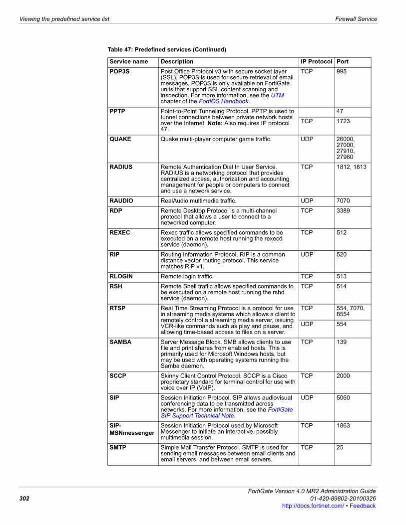
Viewing the predefined service list Firewall Service
302
POP3S Post Office Protocol v3 with secure socket layer (SSL). POP3S is used for secure retrieval of email messages. POP3S is only available on FortiGate units that support SSL content scanning and inspection. For more information, see the UTM chapter of the FortiOS Handbook.
TCP 995
PPTP Point-to-Point Tunneling Protocol. PPTP is used to tunnel connections between private network hosts over the Internet. Note: Also requires IP protocol 47.
47
TCP 1723
QUAKE Quake multi-player computer game traffic. UDP 26000, 27000, 27910, 27960
RADIUS Remote Authentication Dial In User Service. RADIUS is a networking protocol that provides centralized access, authorization and accounting management for people or computers to connect and use a network service.
TCP 1812, 1813
RAUDIO RealAudio multimedia traffic. UDP 7070
RDP Remote Desktop Protocol is a multi-channel protocol that allows a user to connect to a networked computer.
TCP 3389
REXEC Rexec traffic allows specified commands to be executed on a remote host running the rexecd service (daemon).
TCP 512
RIP Routing Information Protocol. RIP is a common distance vector routing protocol. This service matches RIP v1.
UDP 520
RLOGIN Remote login traffic. TCP 513
RSH Remote Shell traffic allows specified commands to be executed on a remote host running the rshd service (daemon).
TCP 514
RTSP Real Time Streaming Protocol is a protocol for use in streaming media systems which allows a client to remotely control a streaming media server, issuing VCR-like commands such as play and pause, and allowing time-based access to files on a server.
TCP 554, 7070, 8554
UDP 554
SAMBA Server Message Block. SMB allows clients to use file and print shares from enabled hosts. This is primarily used for Microsoft Windows hosts, but may be used with operating systems running the Samba daemon.
TCP 139
SCCP Skinny Client Control Protocol. SCCP is a Cisco proprietary standard for terminal control for use with voice over IP (VoIP).
TCP 2000
SIP Session Initiation Protocol. SIP allows audiovisual conferencing data to be transmitted across networks. For more information, see the FortiGate SIP Support Technical Note.
UDP 5060
SIP-MSNmessenger
Session Initiation Protocol used by Microsoft Messenger to initiate an interactive, possibly multimedia session.
TCP 1863
SMTP Simple Mail Transfer Protocol. SMTP is used for sending email messages between email clients and email servers, and between email servers.
TCP 25
Table 47: Predefined services (Continued)
Service name Description IP Protocol Port
FortiGate Version 4.0 MR2 Administration Guide01-420-89802-20100326
http://docs.fortinet.com/ • Feedback
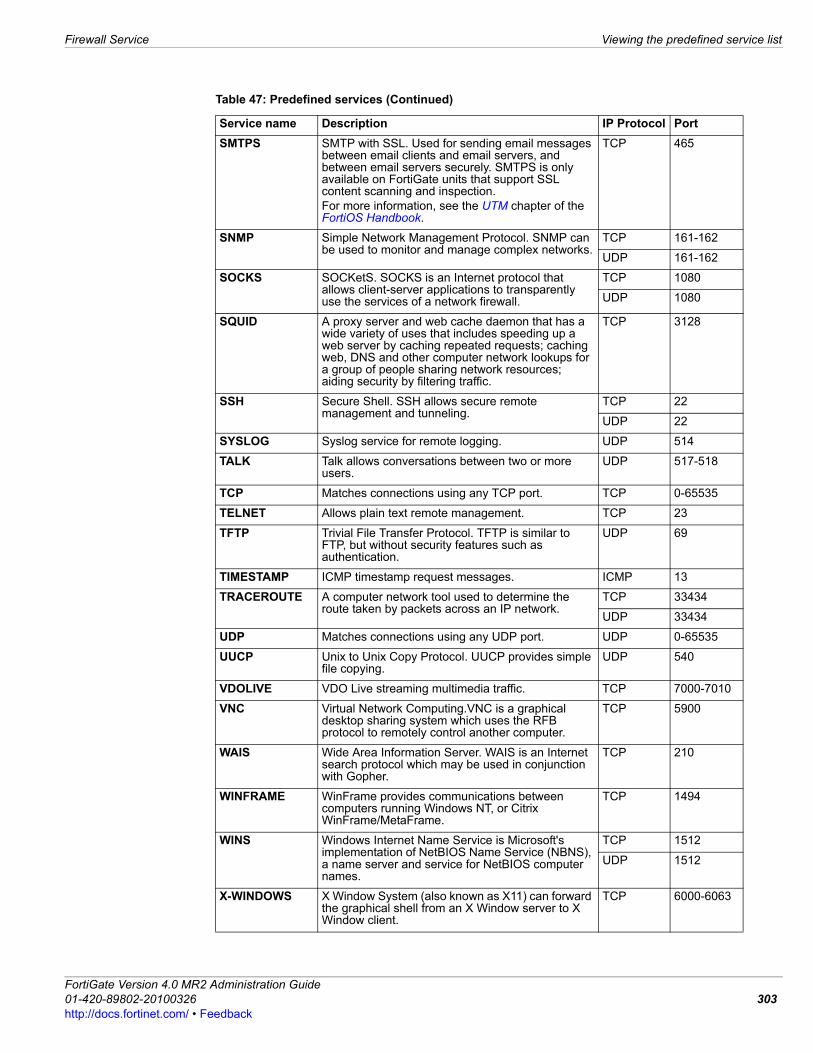
Firewall Service Viewing the predefined service list
SMTPS SMTP with SSL. Used for sending email messages between email clients and email servers, and between email servers securely. SMTPS is only available on FortiGate units that support SSL content scanning and inspection.For more information, see the UTM chapter of the FortiOS Handbook.
TCP 465
SNMP Simple Network Management Protocol. SNMP can be used to monitor and manage complex networks.
TCP 161-162
UDP 161-162
SOCKS SOCKetS. SOCKS is an Internet protocol that allows client-server applications to transparently use the services of a network firewall.
TCP 1080
UDP 1080
SQUID A proxy server and web cache daemon that has a wide variety of uses that includes speeding up a web server by caching repeated requests; caching web, DNS and other computer network lookups for a group of people sharing network resources; aiding security by filtering traffic.
TCP 3128
SSH Secure Shell. SSH allows secure remote management and tunneling.
TCP 22
UDP 22
SYSLOG Syslog service for remote logging. UDP 514
TALK Talk allows conversations between two or more users.
UDP 517-518
TCP Matches connections using any TCP port. TCP 0-65535
TELNET Allows plain text remote management. TCP 23
TFTP Trivial File Transfer Protocol. TFTP is similar to FTP, but without security features such as authentication.
UDP 69
TIMESTAMP ICMP timestamp request messages. ICMP 13
TRACEROUTE A computer network tool used to determine the route taken by packets across an IP network.
TCP 33434
UDP 33434
UDP Matches connections using any UDP port. UDP 0-65535
UUCP Unix to Unix Copy Protocol. UUCP provides simple file copying.
UDP 540
VDOLIVE VDO Live streaming multimedia traffic. TCP 7000-7010
VNC Virtual Network Computing.VNC is a graphical desktop sharing system which uses the RFB protocol to remotely control another computer.
TCP 5900
WAIS Wide Area Information Server. WAIS is an Internet search protocol which may be used in conjunction with Gopher.
TCP 210
WINFRAME WinFrame provides communications between computers running Windows NT, or Citrix WinFrame/MetaFrame.
TCP 1494
WINS Windows Internet Name Service is Microsoft's implementation of NetBIOS Name Service (NBNS), a name server and service for NetBIOS computer names.
TCP 1512
UDP 1512
X-WINDOWS X Window System (also known as X11) can forward the graphical shell from an X Window server to X Window client.
TCP 6000-6063
Table 47: Predefined services (Continued)
Service name Description IP Protocol Port
FortiGate Version 4.0 MR2 Administration Guide01-420-89802-20100326 303http://docs.fortinet.com/ • Feedback

Configuring custom services Firewall Service
304
Configuring custom servicesIf you need to create a firewall policy for a service that is not in the predefined service list, you can add a custom service.To view the custom service list, go to Firewall > Service > Custom.To configure a custom service, go to Firewall > Service > Custom, select Create New, enter the information required for that custom service, and then select OK.
Configuring custom service groupsYou can organize multiple firewall services into a service group to simplify your firewall policy list. For example, instead of having five identical policies for five different but related firewall services, you might combine the five services into a single address group that is used by a single firewall policy.
Tip: You can also create custom services when you configure a firewall policy. Go to Firewall > Policy > Policy, select the appropriate policy tab and then Create New. From the Service list, select Service > Create New.
Custom pageLists each individual custom service that you created. On this page, you can edit, delete or create a new custom service.
Create New Add a custom service. When you select Create New, you are automatically redirected to the New Custom Service page.
Service Name The name of the custom service.
Detail The protocol and port numbers for each custom service.
Delete Remove the custom service. The Delete icon appears only if the service is not currently being used by a firewall policy.
Edit Edit the custom service.
New Custom Service pageProvides settings for configuring a customized service that is not available in the predefined service list.
Name Enter a name for the custom service.
Protocol Type Select the type of protocol for the custom service.
Protocol Select the protocol from the drop-down list that you are configuring settings for.
Source Port Specify the source port number range for the service by entering the low and high port numbers. If the service uses one port number, enter this number in both the Low and High fields. The default values allow the use of any source port.
Destination Port Specify the destination port number range for the service by entering the low and high port numbers. If the service uses one port number, enter this number in both the Low and High fields.
Add If your custom service requires more than one port range, select Add to allow more source and destination ranges.
Delete Remove the protocol entry (TCP, UDP or SCTP) from the list.
Type Enter the ICMP type number for the ICMP protocol configuration.
Code Enter the ICMP code number for the ICMP protocol configuration.
Protocol Number Enter the protocol number for the IP protocol configuration.
FortiGate Version 4.0 MR2 Administration Guide01-420-89802-20100326
http://docs.fortinet.com/ • Feedback
Firewall Service Configuring custom service groups
Service groups can contain both predefined and custom services. Service groups cannot contain other service groups.To view the service group list, go to Firewall > Service > Group.You can organize multiple firewall services into a service group to simplify your firewall policy list. For example, instead of having five identical policies for five different but related firewall services, you might combine the five services into a single service group that is used by a single firewall policy.Service groups can contain both predefined and custom services. Service groups cannot contain other service groups.To organize services into a service group, go to Firewall > Service > Group.
Tip: You can also create custom service groups when you configure a firewall policy. Go to Firewall > Policy > Policy, select the appropriate policy tab and then Create New. From the Service list, select Service Group > Create New.
Group pageLists each individual service group that you created. On this page, you can edit, delete or create a new service group.
Create New Add a service group. When you select Create New, you are automatically redirected to the New Service Group page.
Edit Select to edit the Group Name and Members.
Delete Remove the entry from the list. The Delete icon appears only if the service group is not selected in a firewall policy.
Group Name The name to identify the service group.
Members The services added to the service group.
New Service Group pageProvides settings for defining the services that will be members within a service group.
Group Name Enter a name to identify the service group.
Available Services The list of configured and predefined services available for your group, with custom services at the bottom. Use the arrows to move selected services between this list and Members.
Members The list of services in the group. Use the arrows to move selected services between this list and Available Services.
FortiGate Version 4.0 MR2 Administration Guide01-420-89802-20100326 305http://docs.fortinet.com/ • Feedback

Configuring custom service groups Firewall Service
306
FortiGate Version 4.0 MR2 Administration Guide01-420-89802-20100326http://docs.fortinet.com/ • Feedback
Firewall Schedule Viewing the recurring schedule list
Firewall ScheduleFirewall schedules control when policies are in effect. You can create one-time schedules or recurring schedules. One-time schedules are in effect only once for the period of time specified in the schedule. Recurring schedules are in effect repeatedly at specified times of specified days of the week.If you enable virtual domains (VDOMs) on the FortiGate unit, you must configure firewall schedules separately for each virtual domain. For more information, see “Using virtual domains” on page 73.The following topics are included in this section:• Viewing the recurring schedule list• Configuring recurring schedules• Viewing the one-time schedule list• Configuring one-time schedules• Configuring schedule groups
Viewing the recurring schedule listYou can create a recurring schedule that activates a policy during a specified period of time. For example, you might prevent game playing during office hours by creating a recurring schedule that covers office hours.If a recurring schedule has a stop time that is earlier than the start time, the schedule will take effect at the start time but end at the stop time on the next day. You can use this technique to create recurring schedules that run from one day to the next. For example, to prevent game playing except at lunchtime, you might set the start time for a recurring schedule at 1:00 p.m. and the stop time at 12:00 noon. To create a recurring schedule that runs for 24 hours, set the start and stop times to 00.To view the recurring schedule list, go to Firewall > Schedule > Recurring.
Recurring pageLists each individual recurring schedule that you created. On this page, you can edit, delete or create a new recurring schedule.
Create New Add a recurring schedule.
Name The name of the recurring schedule.
Day The initials of the days of the week on which the schedule is active.
Start The start time of the recurring schedule.
Stop The stop time of the recurring schedule.
Delete Remove the schedule from the list. The Delete icon appears only if the schedule is not being used in a firewall policy.
Edit Edit the schedule.
FortiGate Version 4.0 MR2 Administration Guide01-420-89802-20100326 307http://docs.fortinet.com/ • Feedback
Configuring recurring schedules Firewall Schedule
308
Configuring recurring schedulesTo add a recurring schedule, go to Firewall > Schedule > Recurring. Complete the fields as described in the following table and select OK.
To put a policy into effect for an entire day, set schedule start and stop times to 00.
Viewing the one-time schedule listYou can create a one-time schedule that activates a policy during a specified period of time. For example, a firewall might be configured with a default policy that allows access to all services on the Internet at all times, but you could add a one-time schedule to block access to the Internet during a holiday.To view the one-time schedule list, go to Firewall > Schedule > One-time.
Configuring one-time schedulesTo add a one-time schedule, go to Firewall > Schedule > One-time. Complete the fields as described in the following table and select OK.
To put a policy into effect for an entire day, set schedule start and stop times to 00.
Tip: You can also create recurring schedules when you configure a firewall policy. Go to Firewall > Policy, select the appropriate policy tab and then Create New. From the Schedule list, select Recurring > Create New.
New Recurring Schedule page Provides settings for configuring a schedule that is active on a regular basis.
Name Enter a name to identify the recurring schedule.
Select Select the days of the week for the schedule to be active.
Start Select the start time for the recurring schedule.
Stop Select the stop time for the recurring schedule.
One-time pageLists each individual schedule that only occurs once. On this page, you can edit, delete or create a new one-time schedule.
Create New Add a one-time schedule. When you select Create New, you are automatically redirected to the New One-time Schedule page.
Name The name of the one-time schedule.
Start The start date and time for the schedule.
Stop The stop date and time for the schedule.
Delete Remove the schedule from the list. The Delete icon appears only if the schedule is not being used in a firewall policy.
Edit Edit the schedule.
Tip: You can also create one-time schedules when you configure a firewall policy. Go to Firewall > Policy, select the appropriate policy tab and then Create New. From the Schedule list, select One-time > Create New.
FortiGate Version 4.0 MR2 Administration Guide01-420-89802-20100326
http://docs.fortinet.com/ • Feedback
Firewall Schedule Configuring schedule groups
Configuring schedule groupsYou can organize multiple firewall schedules into a schedule group to simplify your firewall policy list. For example, instead of having five identical policies for five different but related firewall schedules, you might combine the five schedules into a single schedule group that is used by a single firewall policy.Schedule groups can contain both recurring and on-time schedules. Schedule groups cannot contain other schedule groups.To organize schedules into a schedule group, go to Firewall > Schedule > Group.
New One-time Schedule pageProvides settings for configuring a one-time schedule. When you select Create New, you are automatically redirected to this page.
Name Enter a name to identify the one-time schedule.
Start Select the start date and time for the schedule.
Stop Select the stop date and time for the schedule.
Group pageLists each individual schedule group that you created. On this page, you can edit, delete or create a new schedule group.
Group Name Enter a name to identify the schedule group.
Available Schedules
The list of recurring and one-time schedules available for your group. Use the arrow buttons to move selected schedules between this list and Members.
Members The list of schedules in the group. Use the arrows to move selected schedules between this list and Available Schedule.
New Schedule Group pageProvides settings for defining what schedules are members of the group.
Group Name Enter a name for the schedule group.
Available Schedules
Select the schedule that you want to be a member, and then use the down arrow to move that schedule to Members.
Members The schedules that will be associated with the group. To remove a schedule from the Members list, select the schedule and then use the up arrow to move that schedule back to Available Schedules.
FortiGate Version 4.0 MR2 Administration Guide01-420-89802-20100326 309http://docs.fortinet.com/ • Feedback

Configuring schedule groups Firewall Schedule
310
FortiGate Version 4.0 MR2 Administration Guide01-420-89802-20100326http://docs.fortinet.com/ • Feedback
Firewall Virtual IP How virtual IPs map connections through FortiGate units
F0h
Firewall Virtual IPVirtual IP addresses (VIPs) can be used when configuring firewall policies to translate IP addresses and ports of packets received by a network interface, including a modem interface.When the FortiGate unit receives inbound packets matching a firewall policy whose Destination Address field is a virtual IP, the FortiGate unit applies NAT, replacing packets’ IP addresses with the virtual IP’s mapped IP address.IP pools, similarly to virtual IPs, can be used to configure aspects of NAT; however, IP pools configure dynamic translation of packets’ IP addresses based on the Destination Interface/Zone, whereas virtual IPs configure dynamic or static translation of a packets’ IP addresses based upon the Source Interface/Zone.To implement the translation configured in the virtual IP or IP pool, you must add it to a NAT firewall policy. For more information, see “Configuring virtual IPs” on page 315.If you enable virtual domains (VDOMs) on the FortiGate unit, firewall virtual IPs are configured separately for each virtual domain. For more information, see “Using virtual domains” on page 73.The following topics are included in this section:• How virtual IPs map connections through FortiGate units• Viewing the virtual IP list• Configuring virtual IPs• Virtual IP Groups• Viewing the VIP group list• Configuring VIP groups• Configuring IP pools• Viewing the IP pool list• Configuring IP PoolsDouble NAT: combining IP pool with virtual IP• Adding NAT firewall policies in transparent mode
How virtual IPs map connections through FortiGate unitsVirtual IPs can specify translations of packets’ port numbers and/or IP addresses for both inbound and outbound connections. In Transparent mode, virtual IPs are available from the FortiGate CLI.
Inbound connectionsVirtual IPs can be used in conjunction with firewall policies whose Action is not DENY to apply bidirectional NAT, also known as inbound NAT.
Note: In Transparent mode from the FortiGate CLI, you can configure NAT firewall policies that include Virtual IPs and IP pools. See “Adding NAT firewall policies in transparent mode” on page 330.
ortiGate Version 4.0 MR2 Administration Guide1-420-89802-20100326 311ttp://docs.fortinet.com/ • Feedback
How virtual IPs map connections through FortiGate units Firewall Virtual IP
When comparing packets with the firewall policy list to locate a matching policy, if a firewall policy’s Destination Address is a virtual IP, FortiGate units compares packets’ destination address to the virtual IP’s external IP address. If they match, the FortiGate unit applies the virtual IP’s inbound NAT mapping, which specifies how the FortiGate unit translates network addresses and/or port numbers of packets from the receiving (external) network interface to the network interface connected to the destination (mapped) IP address or IP address range.In addition to specifying IP address and port mappings between interfaces, virtual IP configurations can optionally bind an additional IP address or IP address range to the receiving network interface. By binding an additional IP address, you can configure a separate set of mappings that the FortiGate unit can apply to packets whose destination matches that bound IP address, rather than the IP address already configured for the network interface.Depending on your configuration of the virtual IP, its mapping may involve port address translation (PAT), also known as port forwarding or network address port translation (NAPT), and/or network address translation (NAT) of IP addresses.If you configure NAT in the virtual IP and firewall policy, the NAT behavior varies by your selection of:• static vs. dynamic NAT mapping • the dynamic NAT’s load balancing style, if using dynamic NAT mapping• full NAT vs. destination NAT (DNAT)The following table describes combinations of PAT and/or NAT that are possible when configuring a firewall policy with a virtual IP.
Static NAT Static, one-to-one NAT mapping: an external IP address is always translated to the same mapped IP address.If using IP address ranges, the external IP address range corresponds to a mapped IP address range containing an equal number of IP addresses, and each IP address in the external range is always translated to the same IP address in the mapped range.
Static NAT with Port Forwarding
Static, one-to-one NAT mapping with port forwarding: an external IP address is always translated to the same mapped IP address, and an external port number is always translated to the same mapped port number.If using IP address ranges, the external IP address range corresponds to a mapped IP address range containing an equal number of IP addresses, and each IP address in the external range is always translated to the same IP address in the mapped range. If using port number ranges, the external port number range corresponds to a mapped port number range containing an equal number of port numbers, and each port number in the external range is always translated to the same port number in the mapped range.
Server Load Balancing
Dynamic, one-to-many NAT mapping: an external IP address is translated to one of the mapped IP addresses, as determined by the selected load balancing algorithm for more even traffic distribution. The external IP address is not always translated to the same mapped IP address.Server load balancing requires that you configure at least one “real” server, but can use up to eight. Real servers can be configured with health check monitors. Health check monitors can be used to gauge server responsiveness before forwarding packets.
Server Load Balancing with Port Forwarding
Dynamic, one-to-many NAT mapping with port forwarding: an external IP address is translated to one of the mapped IP addresses, as determined by the selected load balancing algorithm for more even traffic distribution. The external IP address is not always translated to the same mapped IP address.Server load balancing requires that you configure at least one “real” server, but can use up to eight. Real servers can be configured with health check monitors. Health check monitors can be used to gauge server responsiveness before forwarding packets.
FortiGate Version 4.0 MR2 Administration Guide312 01-420-89802-20100326
http://docs.fortinet.com/ • Feedback
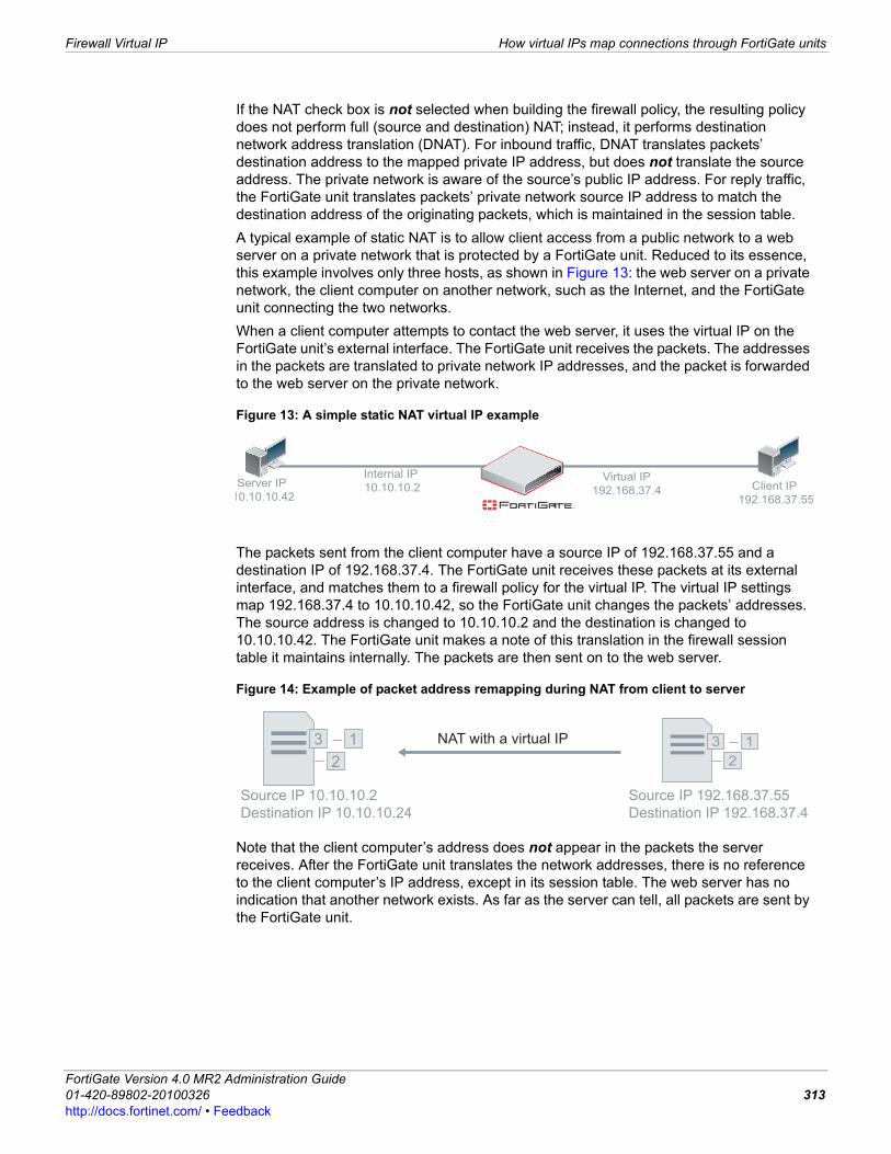
Firewall Virtual IP How virtual IPs map connections through FortiGate units
F0h
If the NAT check box is not selected when building the firewall policy, the resulting policy does not perform full (source and destination) NAT; instead, it performs destination network address translation (DNAT). For inbound traffic, DNAT translates packets’ destination address to the mapped private IP address, but does not translate the source address. The private network is aware of the source’s public IP address. For reply traffic, the FortiGate unit translates packets’ private network source IP address to match the destination address of the originating packets, which is maintained in the session table.A typical example of static NAT is to allow client access from a public network to a web server on a private network that is protected by a FortiGate unit. Reduced to its essence, this example involves only three hosts, as shown in Figure 13: the web server on a private network, the client computer on another network, such as the Internet, and the FortiGate unit connecting the two networks.When a client computer attempts to contact the web server, it uses the virtual IP on the FortiGate unit’s external interface. The FortiGate unit receives the packets. The addresses in the packets are translated to private network IP addresses, and the packet is forwarded to the web server on the private network.
Figure 13: A simple static NAT virtual IP example
The packets sent from the client computer have a source IP of 192.168.37.55 and a destination IP of 192.168.37.4. The FortiGate unit receives these packets at its external interface, and matches them to a firewall policy for the virtual IP. The virtual IP settings map 192.168.37.4 to 10.10.10.42, so the FortiGate unit changes the packets’ addresses. The source address is changed to 10.10.10.2 and the destination is changed to 10.10.10.42. The FortiGate unit makes a note of this translation in the firewall session table it maintains internally. The packets are then sent on to the web server.
Figure 14: Example of packet address remapping during NAT from client to server
Note that the client computer’s address does not appear in the packets the server receives. After the FortiGate unit translates the network addresses, there is no reference to the client computer’s IP address, except in its session table. The web server has no indication that another network exists. As far as the server can tell, all packets are sent by the FortiGate unit.
Server IP
10.10.10.42Client IP
192.168.37.55
Internal IP
10.10.10.2Virtual IP
192.168.37.4
3 1
2
Source IP 10.10.10.2
Destination IP 10.10.10.24
3 1
2
Source IP 192.168.37.55
Destination IP 192.168.37.4
NAT with a virtual IP
ortiGate Version 4.0 MR2 Administration Guide1-420-89802-20100326 313ttp://docs.fortinet.com/ • Feedback
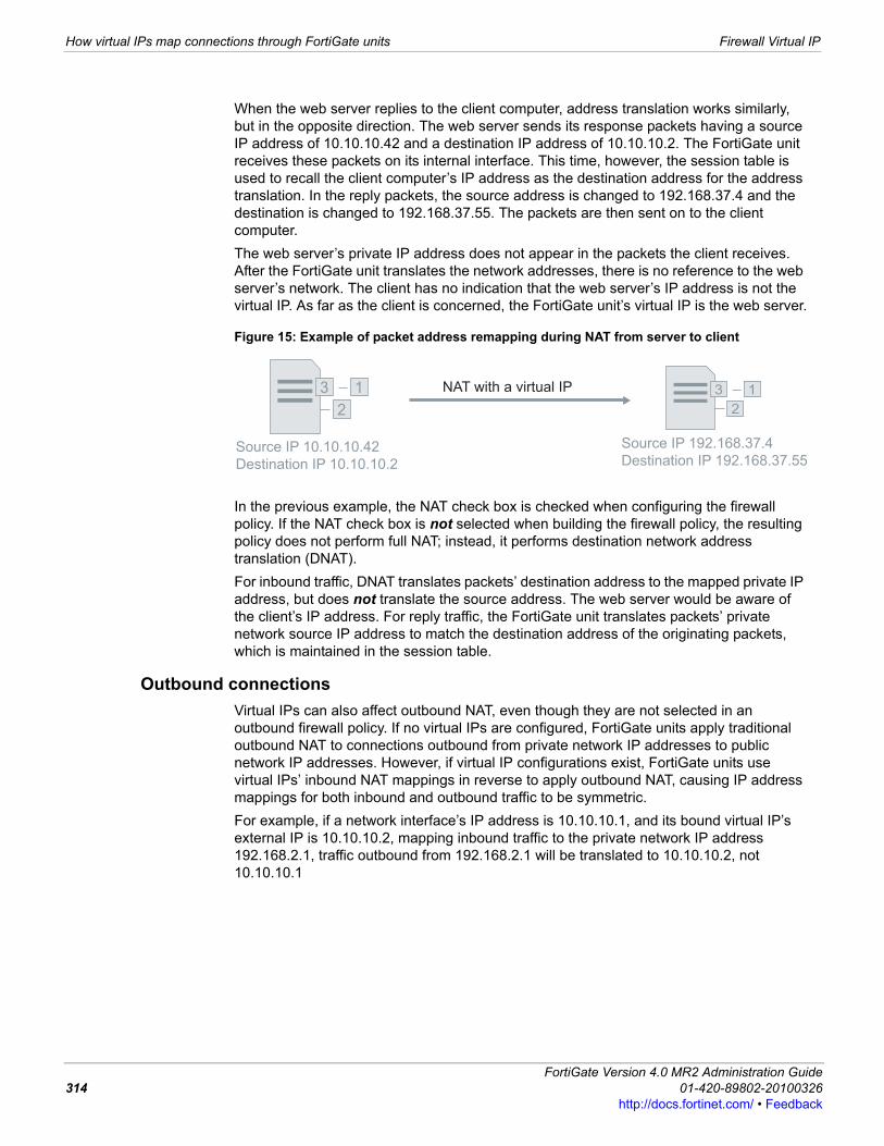
How virtual IPs map connections through FortiGate units Firewall Virtual IP
When the web server replies to the client computer, address translation works similarly, but in the opposite direction. The web server sends its response packets having a source IP address of 10.10.10.42 and a destination IP address of 10.10.10.2. The FortiGate unit receives these packets on its internal interface. This time, however, the session table is used to recall the client computer’s IP address as the destination address for the address translation. In the reply packets, the source address is changed to 192.168.37.4 and the destination is changed to 192.168.37.55. The packets are then sent on to the client computer.The web server’s private IP address does not appear in the packets the client receives. After the FortiGate unit translates the network addresses, there is no reference to the web server’s network. The client has no indication that the web server’s IP address is not the virtual IP. As far as the client is concerned, the FortiGate unit’s virtual IP is the web server.
Figure 15: Example of packet address remapping during NAT from server to client
In the previous example, the NAT check box is checked when configuring the firewall policy. If the NAT check box is not selected when building the firewall policy, the resulting policy does not perform full NAT; instead, it performs destination network address translation (DNAT).For inbound traffic, DNAT translates packets’ destination address to the mapped private IP address, but does not translate the source address. The web server would be aware of the client’s IP address. For reply traffic, the FortiGate unit translates packets’ private network source IP address to match the destination address of the originating packets, which is maintained in the session table.
Outbound connectionsVirtual IPs can also affect outbound NAT, even though they are not selected in an outbound firewall policy. If no virtual IPs are configured, FortiGate units apply traditional outbound NAT to connections outbound from private network IP addresses to public network IP addresses. However, if virtual IP configurations exist, FortiGate units use virtual IPs’ inbound NAT mappings in reverse to apply outbound NAT, causing IP address mappings for both inbound and outbound traffic to be symmetric.For example, if a network interface’s IP address is 10.10.10.1, and its bound virtual IP’s external IP is 10.10.10.2, mapping inbound traffic to the private network IP address 192.168.2.1, traffic outbound from 192.168.2.1 will be translated to 10.10.10.2, not 10.10.10.1
3 1
2
Source IP 10.10.10.42
Destination IP 10.10.10.2
3 1
2
Source IP 192.168.37.4
Destination IP 192.168.37.55
NAT with a virtual IP
FortiGate Version 4.0 MR2 Administration Guide314 01-420-89802-20100326
http://docs.fortinet.com/ • Feedback
Firewall Virtual IP Viewing the virtual IP list
F0h
Virtual IP, load balance virtual server and load balance real server limitationsThe following limitations apply when adding virtual IPs, Load balancing virtual servers, and load balancing real servers. Load balancing virtual servers are actually server load balancing virtual IPs. You can add server load balance virtual IPs from the CLI.
• Virtual IP External IP Address/Range entries or ranges cannot overlap with each other or with load balancing virtual server Virtual Server IP entries.
• A virtual IP Mapped IP Address/Range cannot be 0.0.0.0 or 255.255.255.255.• A real server IP cannot be 0.0.0.0 or 255.255.255.255.• If a static NAT virtual IP External IP Address/Range is 0.0.0.0, the Mapped IP
Address/Range must be a single IP address.• If a load balance virtual IP External IP Address/Range is 0.0.0.0, the Mapped IP
Address/Range can be an address range.• When port forwarding, the count of mapped port numbers and external port
numbers must be the same. The web-based manager does this automatically but the CLI does not.
• Virtual IP and virtual server names must be different from firewall address or address group names.
Viewing the virtual IP listTo view the virtual IP list, go to Firewall > Virtual IP > Virtual IP.
Configuring virtual IPsA virtual IP’s external IP address can be a single IP address or an IP address range, and is bound to a FortiGate unit interface. When you bind the virtual IP’s external IP address to a FortiGate unit interface, by default, the network interface responds to ARP requests for the bound IP address or IP address range. Virtual IPs use proxy ARP, as defined in RFC 1027, so that the FortiGate unit can respond to ARP requests on a network for a server that is actually installed on another network. To disable ARP replies, see the FortiGate CLI Reference.
Virtual IP pageLists each individual virtual IP that you created. On this page, you can edit, delete or create a new virtual IP.
Create New Select to add a virtual IP. When you select Create New, you are automatically redirected to the Add New Virtual IP Mapping page.
Name The name of the virtual IP.
IP The bound network interface and external IP address or IP address, separated by a slash (/).
Service Port The external port number or port number range. This field is empty if the virtual IP does not specify port forwarding.
Map to IP/IP Range
The mapped to IP address or address range on the destination network.
Map to Port The mapped to port number or port number range. This field is empty if the virtual IP does not specify port forwarding.
Delete Remove the virtual IP from the list. The Delete icon only appears if the virtual IP is not selected in a firewall policy.
Edit Edit the virtual IP to change any virtual IP option including the virtual IP name.
ortiGate Version 4.0 MR2 Administration Guide1-420-89802-20100326 315ttp://docs.fortinet.com/ • Feedback
Configuring virtual IPs Firewall Virtual IP
A virtual IP’s mapped IP address can be a single IP address, or an IP address range.When the FortiGate unit receives packets matching a firewall policy whose Destination Address field is a virtual IP, the FortiGate unit applies NAT, replacing the packet’s destination IP address with the virtual IP’s mapped IP address.To implement the translation configured in the virtual IP or IP pool, you must add it to a NAT firewall policy. For example, to add a firewall policy that maps public network addresses to a private network, add an external to internal firewall policy whose Destination Address field is a virtual IP.For limitations on creating virtual IPs, see “Virtual IP, load balance virtual server and load balance real server limitations” on page 315.
To configure a virtual IP1 Go to Firewall > Virtual IP > Virtual IP.2 Select Create New.
Add New Virtual IP Mapping pageProvides settings for configuring a virtual IP.
Name Enter or change the name to identify the virtual IP. To avoid confusion, addresses, address groups, and virtual IPs cannot have the same names.
External Interface Select the virtual IP external interface from the list. The external interface is connected to the source network and receives the packets to be forwarded to the destination network. You can select any FortiGate interface, VLAN subinterface, VPN interface, or modem interface.
Type VIP type is Static NAT, read only.
External IP Address/Range
Enter the external IP address that you want to map to an address on the destination network.To configure a dynamic virtual IP that accepts connections for any IP address, set the external IP address to 0.0.0.0. For a static NAT dynamic virtual IP you can only add one mapped IP address. For a load balance dynamic virtual IP you can specify a single mapped address or a mapped address range.
Mapped IP Address/Range
Enter the real IP address on the destination network to which the external IP address is mapped.You can also enter an address range to forward packets to multiple IP addresses on the destination network.For a static NAT virtual IP, if you add a mapped IP address range the FortiGate unit calculates the external IP address range and adds the IP address range to the External IP Address/Range field.This option appears only if Type is Static NAT.
Port Forwarding Select to perform port address translation (PAT).
Protocol Select the protocol of the forwarded packets.This option appears only if Port Forwarding is enabled.
External Service Port
Enter the external interface port number for which you want to configure port forwarding.This option appears only if Port Forwarding is enabled.
Map to Port Enter the port number on the destination network to which the external port number is mapped.You can also enter a port number range to forward packets to multiple ports on the destination network.For a virtual IP with static NAT, if you add a map to port range the FortiGate unit calculates the external port number range and adds the port number range to the External Service port field.This option appears only if Port Forwarding is enabled.
FortiGate Version 4.0 MR2 Administration Guide316 01-420-89802-20100326
http://docs.fortinet.com/ • Feedback
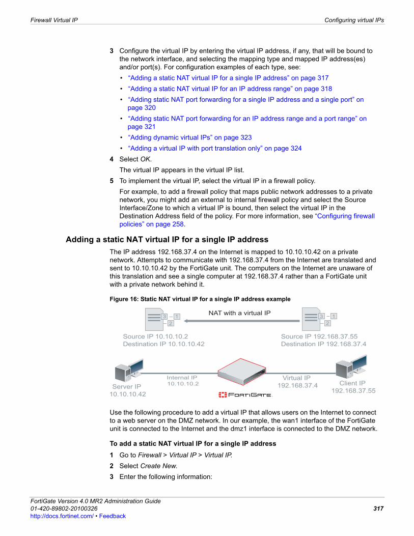
Firewall Virtual IP Configuring virtual IPs
F0h
3 Configure the virtual IP by entering the virtual IP address, if any, that will be bound to the network interface, and selecting the mapping type and mapped IP address(es) and/or port(s). For configuration examples of each type, see:• “Adding a static NAT virtual IP for a single IP address” on page 317• “Adding a static NAT virtual IP for an IP address range” on page 318• “Adding static NAT port forwarding for a single IP address and a single port” on
page 320• “Adding static NAT port forwarding for an IP address range and a port range” on
page 321• “Adding dynamic virtual IPs” on page 323• “Adding a virtual IP with port translation only” on page 324
4 Select OK.The virtual IP appears in the virtual IP list.
5 To implement the virtual IP, select the virtual IP in a firewall policy.For example, to add a firewall policy that maps public network addresses to a private network, you might add an external to internal firewall policy and select the Source Interface/Zone to which a virtual IP is bound, then select the virtual IP in the Destination Address field of the policy. For more information, see “Configuring firewall policies” on page 258.
Adding a static NAT virtual IP for a single IP addressThe IP address 192.168.37.4 on the Internet is mapped to 10.10.10.42 on a private network. Attempts to communicate with 192.168.37.4 from the Internet are translated and sent to 10.10.10.42 by the FortiGate unit. The computers on the Internet are unaware of this translation and see a single computer at 192.168.37.4 rather than a FortiGate unit with a private network behind it.
Figure 16: Static NAT virtual IP for a single IP address example
Use the following procedure to add a virtual IP that allows users on the Internet to connect to a web server on the DMZ network. In our example, the wan1 interface of the FortiGate unit is connected to the Internet and the dmz1 interface is connected to the DMZ network.
To add a static NAT virtual IP for a single IP address1 Go to Firewall > Virtual IP > Virtual IP. 2 Select Create New.3 Enter the following information:
3 1
2
Source IP 10.10.10.2
Destination IP 10.10.10.42
3 1
2
Source IP 192.168.37.55
Destination IP 192.168.37.4
NAT with a virtual IP
Server IP
10.10.10.42
Client IP
192.168.37.55
Internal IP
10.10.10.2Virtual IP
192.168.37.4
ortiGate Version 4.0 MR2 Administration Guide1-420-89802-20100326 317ttp://docs.fortinet.com/ • Feedback
Configuring virtual IPs Firewall Virtual IP
4 Select OK.
To add a static NAT virtual IP for a single IP address to a firewall policyAdd a external to dmz1 firewall policy that uses the virtual IP so that when users on the Internet attempt to connect to the web server IP address packets pass through the FortiGate unit from the external interface to the dmz1 interface. The virtual IP translates the destination address of these packets from the external IP to the DMZ network IP address of the web server.1 Go to Firewall > Policy > Policy and select Create New.2 Configure the firewall policy:
3 Select NAT.4 Select OK.
Adding a static NAT virtual IP for an IP address rangeThe IP address range 192.168.37.4-192.168.37.6 on the Internet is mapped to 10.10.10.42-10.10.123.44 on a private network. Packets from Internet computers communicating with 192.168.37.4 are translated and sent to 10.10.10.42 by the FortiGate unit. Similarly, packets destined for 192.168.37.5 are translated and sent to 10.10.10.43, and packets destined for 192.168.37.6 are translated and sent to 10.10.10.44. The computers on the Internet are unaware of this translation and see three computers with individual IP addresses rather than a FortiGate unit with a private network behind it.
Name static_NAT
External Interface wan1
Type Static NAT
External IP Address/Range
The Internet IP address of the web server. The external IP address is usually a static IP address obtained from your ISP for your web server. This address must be a unique IP address that is not used by another host and cannot be the same as the IP address of the external interface the virtual IP will be using. However, the external IP address must be routed to the selected interface. The virtual IP address and the external IP address can be on different subnets. When you add the virtual IP, the external interface responds to ARP requests for the external IP address.
Mapped IP Address/Range
The IP address of the server on the internal network. Since there is only one IP address, leave the second field blank.
Source Interface/Zone external
Source Address All (or a more specific address)
Destination Interface/Zone dmz1
Destination Address simple_static_nat
Schedule always
Service HTTP
Action ACCEPT
FortiGate Version 4.0 MR2 Administration Guide318 01-420-89802-20100326
http://docs.fortinet.com/ • Feedback
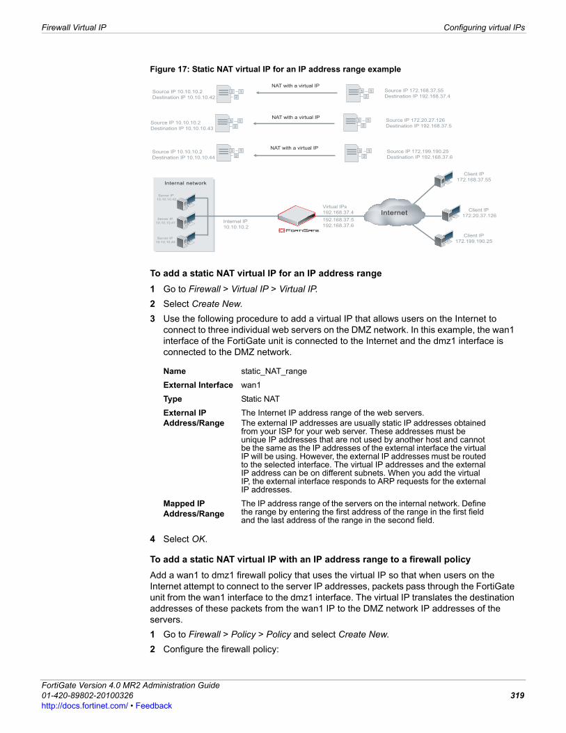
Firewall Virtual IP Configuring virtual IPs
F0h
Figure 17: Static NAT virtual IP for an IP address range example
To add a static NAT virtual IP for an IP address range1 Go to Firewall > Virtual IP > Virtual IP. 2 Select Create New.3 Use the following procedure to add a virtual IP that allows users on the Internet to
connect to three individual web servers on the DMZ network. In this example, the wan1 interface of the FortiGate unit is connected to the Internet and the dmz1 interface is connected to the DMZ network.
4 Select OK.
To add a static NAT virtual IP with an IP address range to a firewall policyAdd a wan1 to dmz1 firewall policy that uses the virtual IP so that when users on the Internet attempt to connect to the server IP addresses, packets pass through the FortiGate unit from the wan1 interface to the dmz1 interface. The virtual IP translates the destination addresses of these packets from the wan1 IP to the DMZ network IP addresses of the servers.1 Go to Firewall > Policy > Policy and select Create New.2 Configure the firewall policy:
Name static_NAT_range
External Interface wan1
Type Static NAT
External IP Address/Range
The Internet IP address range of the web servers. The external IP addresses are usually static IP addresses obtained from your ISP for your web server. These addresses must be unique IP addresses that are not used by another host and cannot be the same as the IP addresses of the external interface the virtual IP will be using. However, the external IP addresses must be routed to the selected interface. The virtual IP addresses and the external IP address can be on different subnets. When you add the virtual IP, the external interface responds to ARP requests for the external IP addresses.
Mapped IP Address/Range
The IP address range of the servers on the internal network. Define the range by entering the first address of the range in the first field and the last address of the range in the second field.
3 1
2
Source IP 10.10.10.2
Destination IP 10.10.10.42
3 1
2Source IP 10.10.10.2
Destination IP 10.10.10.44
3 1
2Source IP 10.10.10.2
Destination IP 10.10.10.43
3 1
2
Source IP 172.168.37.55
Destination IP 192.168.37.4
3 1
2
Source IP 172.20.27.126
Destination IP 192.168.37.5
3 1
2
Source IP 172.199.190.25
Destination IP 192.168.37.6
NAT with a virtual IP
NAT with a virtual IP
NAT with a virtual IP
Internal network
InternetClient IP
172.20.37.126
Client IP
172.199.190.25
Server IP
10.10.10.42
Server IP
10.10.10.41
Server IP
10.10.10.44
Internal IP
10.10.10.2
Virtual IPs
192.168.37.4
192.168.37.5
192.168.37.6
Client IP
172.168.37.55
ortiGate Version 4.0 MR2 Administration Guide1-420-89802-20100326 319ttp://docs.fortinet.com/ • Feedback
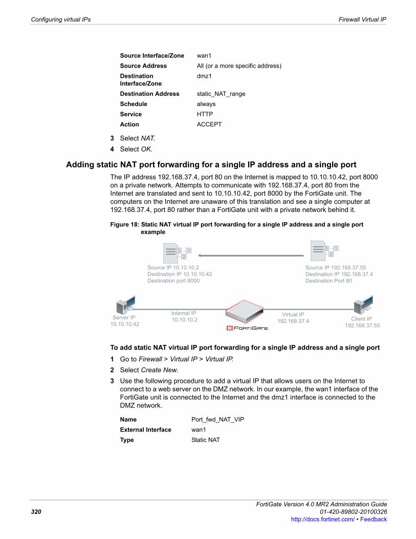
Configuring virtual IPs Firewall Virtual IP
3 Select NAT.4 Select OK.
Adding static NAT port forwarding for a single IP address and a single portThe IP address 192.168.37.4, port 80 on the Internet is mapped to 10.10.10.42, port 8000 on a private network. Attempts to communicate with 192.168.37.4, port 80 from the Internet are translated and sent to 10.10.10.42, port 8000 by the FortiGate unit. The computers on the Internet are unaware of this translation and see a single computer at 192.168.37.4, port 80 rather than a FortiGate unit with a private network behind it.
Figure 18: Static NAT virtual IP port forwarding for a single IP address and a single port example
To add static NAT virtual IP port forwarding for a single IP address and a single port1 Go to Firewall > Virtual IP > Virtual IP. 2 Select Create New.3 Use the following procedure to add a virtual IP that allows users on the Internet to
connect to a web server on the DMZ network. In our example, the wan1 interface of the FortiGate unit is connected to the Internet and the dmz1 interface is connected to the DMZ network.
Source Interface/Zone wan1
Source Address All (or a more specific address)
Destination Interface/Zone
dmz1
Destination Address static_NAT_range
Schedule always
Service HTTP
Action ACCEPT
Name Port_fwd_NAT_VIP
External Interface wan1
Type Static NAT
Server IP
10.10.10.42Client IP
192.168.37.55
Internal IP
10.10.10.2Virtual IP
192.168.37.4
3 1
2
Source IP 10.10.10.2
Destination IP 10.10.10.42
Destination port 8000
3 1
2
Source IP 192.168.37.55
Destination IP 192.168.37.4
Destination Port 80
FortiGate Version 4.0 MR2 Administration Guide320 01-420-89802-20100326
http://docs.fortinet.com/ • Feedback
Firewall Virtual IP Configuring virtual IPs
F0h
4 Select OK.
To add static NAT virtual IP port forwarding for a single IP address and a single port to a firewall policyAdd a wan1 to dmz1 firewall policy that uses the virtual IP so that when users on the Internet attempt to connect to the web server IP addresses, packets pass through the FortiGate unit from the wan1 interface to the dmz1 interface. The virtual IP translates the destination addresses and ports of these packets from the external IP to the dmz network IP addresses of the web servers.1 Go to Firewall > Policy > Policy and select Create New.2 Configure the firewall policy:
3 Select NAT.4 Select OK.
Adding static NAT port forwarding for an IP address range and a port rangePorts 80 to 83 of addresses 192.168.37.4 to 192.168.37.7 on the Internet are mapped to ports 8000 to 8003 of addresses 10.10.10.42 to 10.10.10.44 on a private network. Attempts to communicate with 192.168.37.5, port 82 from the Internet, for example, are translated and sent to 10.10.10.43, port 8002 by the FortiGate unit. The computers on the Internet are unaware of this translation and see a single computer at 192.168.37.5 rather than a FortiGate unit with a private network behind it.
External IP Address/Range
The Internet IP address of the web server. The external IP address is usually a static IP address obtained from your ISP for your web server. This address must be a unique IP address that is not used by another host and cannot be the same as the IP address of the external interface the virtual IP will be using. However, the external IP address must be routed to the selected interface. The virtual IP address and the external IP address can be on different subnets. When you add the virtual IP, the external interface responds to ARP requests for the external IP address.
Mapped IP Address/Range
The IP address of the server on the internal network. Since there is only one IP address, leave the second field blank.
Port Forwarding Selected
Protocol TCP
External Service Port The port traffic from the Internet will use. For a web server, this will typically be port 80.
Map to Port The port on which the server expects traffic. Since there is only one port, leave the second field blank.
Source Interface/Zone wan1
Source Address All (or a more specific address)
Destination Interface/Zone
dmz1
Destination Address Port_fwd_NAT_VIP
Schedule always
Service HTTP
Action ACCEPT
ortiGate Version 4.0 MR2 Administration Guide1-420-89802-20100326 321ttp://docs.fortinet.com/ • Feedback
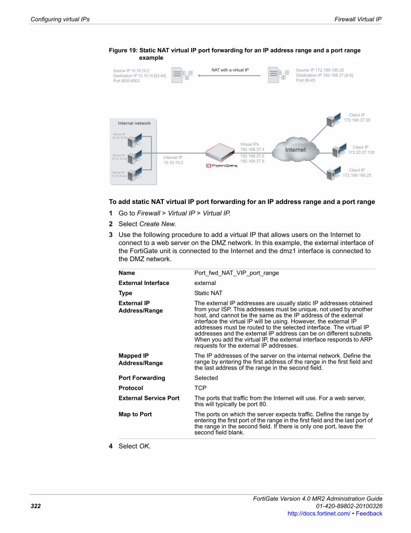
Configuring virtual IPs Firewall Virtual IP
Figure 19: Static NAT virtual IP port forwarding for an IP address range and a port range example
To add static NAT virtual IP port forwarding for an IP address range and a port range1 Go to Firewall > Virtual IP > Virtual IP. 2 Select Create New.3 Use the following procedure to add a virtual IP that allows users on the Internet to
connect to a web server on the DMZ network. In this example, the external interface of the FortiGate unit is connected to the Internet and the dmz1 interface is connected to the DMZ network.
4 Select OK.
Name Port_fwd_NAT_VIP_port_range
External Interface external
Type Static NAT
External IP Address/Range
The external IP addresses are usually static IP addresses obtained from your ISP. This addresses must be unique, not used by another host, and cannot be the same as the IP address of the external interface the virtual IP will be using. However, the external IP addresses must be routed to the selected interface. The virtual IP addresses and the external IP address can be on different subnets. When you add the virtual IP, the external interface responds to ARP requests for the external IP addresses.
Mapped IP Address/Range
The IP addresses of the server on the internal network. Define the range by entering the first address of the range in the first field and the last address of the range in the second field.
Port Forwarding Selected
Protocol TCP
External Service Port The ports that traffic from the Internet will use. For a web server, this will typically be port 80.
Map to Port The ports on which the server expects traffic. Define the range by entering the first port of the range in the first field and the last port of the range in the second field. If there is only one port, leave the second field blank.
3 1
2
Source IP 10.10.10.2
Destination IP 10.10.10.[42-44]
Port 8000-8003
3 1
2
Source IP 172.199.190.25
Destination IP 192.168.37.[4-6]
Port 80-83
NAT with a virtual IP
Internal network
InternetClient IP
172.20.37.126
Client IP
172.199.190.25
Server IP
10.10.10.42
Server IP
10.10.10.43
Server IP
10.10.10.44
Internal IP
10.10.10.2
Virtual IPs
192.168.37.4
192.168.37.5
192.168.37.6
Client IP
172.168.37.55
FortiGate Version 4.0 MR2 Administration Guide322 01-420-89802-20100326
http://docs.fortinet.com/ • Feedback
Firewall Virtual IP Configuring virtual IPs
F0h
To add static NAT virtual IP port forwarding for an IP address range and a port range to a firewall policyAdd a external to dmz1 firewall policy that uses the virtual IP so that when users on the Internet attempt to connect to the web server IP addresses, packets pass through the FortiGate unit from the external interface to the dmz1 interface. The virtual IP translates the destination addresses and ports of these packets from the external IP to the dmz network IP addresses of the web servers.1 Go to Firewall > Policy > Policy and select Create New.2 Configure the firewall policy:
3 Select NAT.4 Select OK.
Adding dynamic virtual IPsAdding a dynamic virtual IP is similar to adding a virtual IP. The difference is that the External IP address must be set to 0.0.0.0 so the External IP address matches any IP address.
To add a dynamic virtual IP1 Go to Firewall > Virtual IP > Virtual IP.2 Select Create New.3 Enter a name for the dynamic virtual IP.4 Select the virtual IP External Interface from the list.
The external interface is connected to the source network and receives the packets to be forwarded to the destination network.Select any firewall interface or a VLAN subinterface.
5 Set the External IP Address to 0.0.0.0.The 0.0.0.0 External IP Address matches any IP address.
6 Enter the Mapped IP Address to which to map the external IP address. For example, the IP address of a PPTP server on an internal network.
7 Select Port Forwarding.8 For Protocol, select TCP.9 Enter the External Service Port number for which to configure dynamic port forwarding.
The external service port number must match the destination port of the packets to be forwarded. For example, if the virtual IP provides PPTP passthrough access from the Internet to a PPTP server, the external service port number should be 1723 (the PPTP port).
Source Interface/Zone external
Source Address All (or a more specific address)
Destination Interface/Zone
dmz1
Destination Address Port_fwd_NAT_VIP_port_range
Schedule always
Service HTTP
Action ACCEPT
ortiGate Version 4.0 MR2 Administration Guide1-420-89802-20100326 323ttp://docs.fortinet.com/ • Feedback
Configuring virtual IPs Firewall Virtual IP
10 Enter the Map to Port number to be added to packets when they are forwarded.Enter the same number as the External Service Port if the port is not to be translated.
11 Select OK.
Adding a virtual IP with port translation onlyWhen adding a virtual IP, if you enter a virtual IP address that is the same as the mapped IP address and apply port forwarding, the destination IP address will be unchanged, but the port number will be translated.
To add a virtual IP with port translation only1 Go to Firewall > Virtual IP > Virtual IP.2 Select Create New.3 Enter a name for the dynamic virtual IP.4 Select the virtual IP External Interface from the list.
The external interface is connected to the source network and receives the packets to be forwarded to the destination network.Select any firewall interface or a VLAN subinterface.
5 Set the External IP Address as the mapped IP address.6 Enter the Mapped IP Address to which to map the external IP address. For example,
the IP address of a PPTP server on an internal network.7 Select Port Forwarding.8 For Protocol, select TCP.9 Enter the External Service Port number for which to configure dynamic port forwarding.
The external service port number must match the destination port of the packets to be forwarded. For example, if the virtual IP provides PPTP passthrough access from the Internet to a PPTP server, the external service port number should be 1723 (the PPTP port).
10 Enter the Map to Port number to be added to packets when they are forwarded.11 Select OK.
In some cases, when you have completed this configuration the FortiGate unit will drop the packets received on the External Interface. To make sure this does not happen, you can log in to the FortiGate CLI and use the following procedure to disable arp replies for the port translation only virtual IP.
To disable arp-reply1 Log into the FortiGate CLI.2 Enter the following command where <vip_name> is the name of the port translation
only virtual IP.config firewall vipedit <vip_name>set arp-reply disable
end
Note: To apply port forwarding to the external interface without binding a virtual IP address to it, enter the IP address of the network interface instead of a virtual IP address, then configure port forwarding as usual.
FortiGate Version 4.0 MR2 Administration Guide324 01-420-89802-20100326
http://docs.fortinet.com/ • Feedback

Firewall Virtual IP Virtual IP Groups
F0h
Virtual IP GroupsYou can organize multiple virtual IPs into a virtual IP group to simplify your firewall policy list. For example, instead of having five identical policies for five different but related virtual IPs located on the same network interface, you might combine the five virtual IPs into a single virtual IP group, which is used by a single firewall policy.Firewall policies using VIP Groups are matched by comparing both the member VIP IP address(es) and port number(s).
Viewing the VIP group listTo view the virtual IP group list, go to Firewall > Virtual IP > VIP Group.
Configuring VIP groupsTo add a VIP group, go to Firewall > Virtual IP > VIP Group and select Create New. To edit a VIP group, go to Firewall > Virtual IP > VIP Group and select the Edit icon for the VIP group to edit. Enter the information as described below, and select OK.
Configuring IP poolsUse IP pools to add NAT policies that translate source addresses to addresses randomly selected from the IP pool, rather than the IP address assigned to that FortiGate unit interface. In Transparent mode, IP pools are available only from the FortiGate CLI.An IP pool defines a single IP address or a range of IP addresses. A single IP address in an IP pool becomes a range of one IP address. For example, if you enter an IP pool as 1.1.1.1 the IP pool is actually the address range 1.1.1.1 to 1.1.1.1.
VIP Group pageLists each individual VIP group that you created. On this page, you can edit, delete or create a new VIP group.
Create New Select to add a new VIP group. See “Configuring VIP groups” on page 325. When you select Create New, you are automatically redirected to the New VIP Group page.
Group Name The name of the virtual IP group.
Members Lists the group members.
Interface Displays the interface that the VIP group belongs to.
Delete Remove the VIP group from the list. The Delete icon only appears if the VIP group is not being used in a firewall policy.
Edit Edit the VIP group information, including the group name and membership.
New VIP Group pageProvides settings for defining VIPs in a group.
Group Name Enter or modify the group name.
Interface Select the interface for which you want to create the VIP group. If you are editing the group, the Interface box is grayed out.
Available VIPs and Members
Select the up or down arrow to move virtual IPs between Available VIPs and Members. Members contains virtual IPs that are a part of this virtual IP group.
ortiGate Version 4.0 MR2 Administration Guide1-420-89802-20100326 325ttp://docs.fortinet.com/ • Feedback
Configuring IP pools Firewall Virtual IP
If a FortiGate interface IP address overlaps with one or more IP pool address ranges, the interface responds to ARP requests for all of the IP addresses in the overlapping IP pools.For example, consider a FortiGate unit with the following IP addresses for the port1 and port2 interfaces:• port1 IP address: 1.1.1.1/255.255.255.0 (range is 1.1.1.0-1.1.1.255)• port2 IP address: 2.2.2.2/255.255.255.0 (range is 2.2.2.0-2.2.2.255)And the following IP pools:• IP_pool_1: 1.1.1.10-1.1.1.20• IP_pool_2: 2.2.2.10-2.2.2.20• IP_pool_3: 2.2.2.30-2.2.2.40The port1 interface overlap IP range with IP_pool_1 is:• (1.1.1.0-1.1.1.255) and (1.1.1.10-1.1.1.20) = 1.1.1.10-1.1.1.20The port2 interface overlap IP range with IP_pool_2 is:• (2.2.2.0-2.2.2.255) & (2.2.2.10-2.2.2.20) = 2.2.2.10-2.2.2.20The port2 interface overlap IP range with IP_pool_3 is:• (2.2.2.0-2.2.2.255) & (2.2.2.30-2.2.2.40) = 2.2.2.30-2.2.2.40And the result is:• The port1 interface answers ARP requests for 1.1.1.10-1.1.1.20• The port2 interface answers ARP requests for 2.2.2.10-2.2.2.20 and for 2.2.2.30-
2.2.2.40Select NAT in a firewall policy and then select Dynamic IP Pool and select an IP pool to translate the source address of packets leaving the FortiGate unit to an address randomly selected from the IP pool.
IP pools and dynamic NATUse IP pools for dynamic NAT. For example, an organization might have purchased a range of Internet addresses but has only one Internet connection on the external interface of the FortiGate unit. Assign one of the organization’s Internet IP addresses to the external interface of the FortiGate unit. If the FortiGate unit is operating in NAT/Route mode, all connections from the organization’s network to the Internet appear to come from this IP address.For connections to originate from all the Internet IP addresses, add this address range to an IP pool. Then select Dynamic IP Pool for all policies with the external interface as the destination. For each connection, the firewall dynamically selects an IP address from the IP pool to be the source address for the connection. As a result, connections to the Internet appear to be originating from any of the IP addresses in the IP pool.
IP Pools for firewall policies that use fixed portsSome network configurations do not operate correctly if a NAT policy translates the source port of packets used by the connection. NAT translates source ports to keep track of connections for a particular service. From the CLI you can enabled fixedport for NAT policies to prevent source port translation. However, enabling fixedport means that only one connection can be supported through the firewall for this service. To be able to support multiple connections, add an IP pool, and then select Dynamic IP pool in the policy. The firewall randomly selects an IP address from the IP pool and assigns it to each connection. In this case the number of connections that the firewall can support is limited by the number of IP addresses in the IP pool.
FortiGate Version 4.0 MR2 Administration Guide326 01-420-89802-20100326
http://docs.fortinet.com/ • Feedback
Firewall Virtual IP Viewing the IP pool list
F0h
Source IP address and IP pool address matchingWhen the source addresses are translated to the IP pool addresses, one of the following three cases may occur:
Scenario 1: The number of source addresses equals that of IP pool addressesIn this case, the FortiGate unit always matches the IP addressed one to one. If you enable fixedport in such a case, the FortiGate unit preserves the original source port. This may cause conflicts if more than one firewall policy uses the same IP pool, or the same IP addresses are used in more than one IP pool.
Scenario 2: The number of source addresses is more than that of IP pool addressesIn this case, the FortiGate unit translates IP addresses using a wrap-around mechanism.If you enable fixedport in such a case, the FortiGate unit preserves the original source port. But conflicts may occur since users may have different sessions using the same TCP 5 tuples.
Scenario 3: The number of source addresses is fewer than that of IP pool addressesIn this case, some of the IP pool addresses are used and the rest of them are not be used.
Viewing the IP pool listIf virtual domains are enabled on the FortiGate unit, IP pools are created separately for each virtual domain. To access IP pools, select a virtual domain from the list on the main menu.
Original address Change to192.168.1.1 172.16.30.1
192.168.1.2 172.16.30.2
192.168.1.254 172.16.30.254
Original address Change to192.168.1.1 172.16.30.10
192.168.1.2 172.16.30.11
192.168.1.10 172.16.30.19
192.168.1.11 172.16.30.10
192.168.1.12 172.16.30.11
192.168.1.13 172.16.30.12
Original address Change to192.168.1.1 172.16.30.10
192.168.1.2 172.16.30.11
192.168.1.3 172.16.30.12
No more source addresses 172.16.30.13 and other addresses are not used
ortiGate Version 4.0 MR2 Administration Guide1-420-89802-20100326 327ttp://docs.fortinet.com/ • Feedback
Configuring IP Pools Firewall Virtual IP
To view the IP pool list go to Firewall > Virtual IP > IP Pool.
Configuring IP PoolsA single IP address is entered normally. For example, 192.168.110.100 is a valid IP pool address. If an IP address range is required, use either of the following formats.• x.x.x.x-x.x.x.x, for example 192.168.110.100-192.168.110.120• x.x.x.[x-x], for example 192.168.110.[100-120]To add an IP pool, go to Firewall > Virtual IP > IP Pool.
Double NAT: combining IP pool with virtual IPWhen creating a firewall policy, you can use both IP pool and virtual IP for double IP and/or port translation. For example, in the following network topology:• Users in the 10.1.1.0/24 subnet use port 8080 to access server 172.16.1.1.• The server’s listening port is 80.• Fixed ports must be used.
IP Pool pageLists each individual IP pool that you created. On this page, you can edit, delete or create a new IP pool.
Create New Select to add an IP pool. When you select Create New, you are automatically redirected to the New Dynamic IP Pool page.
Name The name of the IP pool. Select this name in a firewall policy.
Start IP Enter the start IP defines the start of the IP pool address range.
End IP Enter the end IP defines the end of the IP pool address range.
Delete Select to remove the entry from the list. The Delete icon only appears if the IP pool is not being used in a firewall policy.
Edit Select to edit the IP pool. You can change the Name, Interface, IP Range/Subnet.
New Dynamic IP Pool pageProvides settings for configuring the IP address range and subnet for the IP pool. You can also enter a single IP address for the IP pool.
Name Enter the name of the IP pool.
IP Range/Subnet Enter the IP address range for the IP pool. The IP range defines the start and end of an address range. The start of the range must be lower than the end of the range. The start and end of the IP range does not have to be on the same subnet as the IP address of the interface to which you are adding the IP pool.
FortiGate Version 4.0 MR2 Administration Guide328 01-420-89802-20100326
http://docs.fortinet.com/ • Feedback
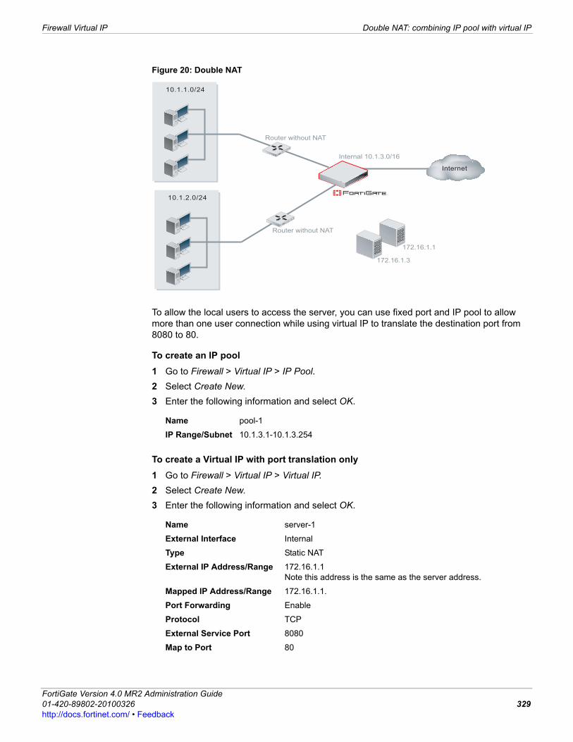
Firewall Virtual IP Double NAT: combining IP pool with virtual IP
F0h
Figure 20: Double NAT
To allow the local users to access the server, you can use fixed port and IP pool to allow more than one user connection while using virtual IP to translate the destination port from 8080 to 80.
To create an IP pool1 Go to Firewall > Virtual IP > IP Pool. 2 Select Create New.3 Enter the following information and select OK.
To create a Virtual IP with port translation only1 Go to Firewall > Virtual IP > Virtual IP.2 Select Create New.3 Enter the following information and select OK.
Name pool-1
IP Range/Subnet 10.1.3.1-10.1.3.254
Name server-1
External Interface Internal
Type Static NAT
External IP Address/Range 172.16.1.1Note this address is the same as the server address.
Mapped IP Address/Range 172.16.1.1.
Port Forwarding Enable
Protocol TCP
External Service Port 8080
Map to Port 80
10.1.1.0/24
10.1.2.0/24
Router without NAT
Router without NAT
Internet
172.16.1.1
172.16.1.3
Internal 10.1.3.0/16
ortiGate Version 4.0 MR2 Administration Guide1-420-89802-20100326 329ttp://docs.fortinet.com/ • Feedback
Adding NAT firewall policies in transparent mode Firewall Virtual IP
To create a firewall policyAdd an internal to dmz firewall policy that uses the virtual IP to translate the destination port number and the IP pool to translate the source addresses. 1 Go to Firewall > Policy.2 Select Create New.3 Configure the firewall policy:
4 Select OK.
Adding NAT firewall policies in transparent modeSimilar to operating in NAT/Route mode, when operating a FortiGate unit in Transparent mode you can add firewall policies and:• Enable NAT to translate the source addresses of packets as they pass through the
FortiGate unit. • Add virtual IPs to translate destination addresses of packets as they pass through the
FortiGate unit.• Add IP pools as required for source address translationFor NAT firewall policies to work in NAT/Route mode you must have two interfaces on two different networks with two different subnet addresses. Then you can create firewall policies to translate source or destination addresses for packets as they are relayed by the FortiGate unit from one interface to the other.A FortiGate unit operating in Transparent mode normally has only one IP address, the management IP. To support NAT in Transparent mode you can add a second management IP. These two management IPs must be on different subnets. When you add two management IP addresses, all FortiGate unit network interfaces will respond to connections to both of these IP addresses.In the example shown in Figure 21, all of the PCs on the internal network (subnet address 192.168.1.0/24) are configured with 192.168.1.99 as their default route. One of the management IPs of the FortiGate unit is set to 192.168.1.99. This configuration results in a typical NAT mode firewall. When a PC on the internal network attempts to connect to the Internet, the PC's default route sends packets destined for the Internet to the FortiGate unit internal interface.Similarly on the DMZ network (subnet address 10.1.1.0/24) all of the PCs have a default route of 10.1.1.99.
Source Interface/Zone internal
Source Address 10.1.1.0/24
Destination Interface/Zone
dmz
Destination Address server-1
Schedule always
Service HTTP
Action ACCEPT
NAT Select
Dynamic IP Pool Select, and select the pool-1 IP pool.
FortiGate Version 4.0 MR2 Administration Guide330 01-420-89802-20100326
http://docs.fortinet.com/ • Feedback
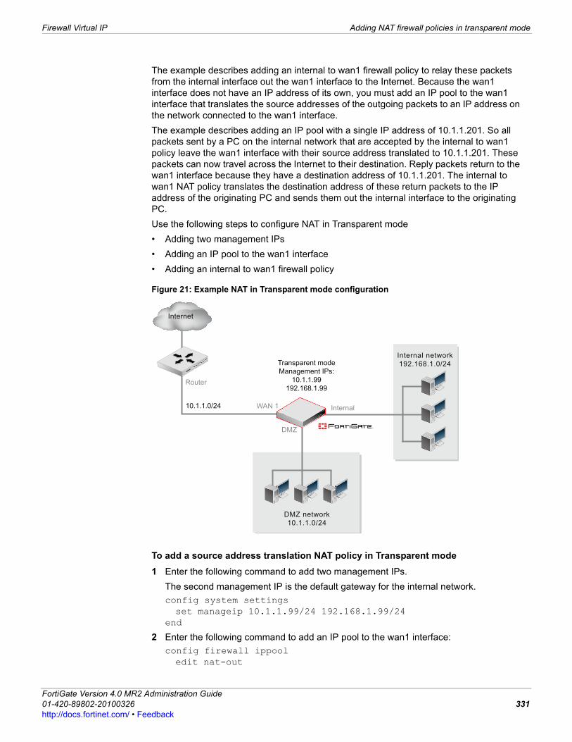
Firewall Virtual IP Adding NAT firewall policies in transparent mode
F0h
The example describes adding an internal to wan1 firewall policy to relay these packets from the internal interface out the wan1 interface to the Internet. Because the wan1 interface does not have an IP address of its own, you must add an IP pool to the wan1 interface that translates the source addresses of the outgoing packets to an IP address on the network connected to the wan1 interface.The example describes adding an IP pool with a single IP address of 10.1.1.201. So all packets sent by a PC on the internal network that are accepted by the internal to wan1 policy leave the wan1 interface with their source address translated to 10.1.1.201. These packets can now travel across the Internet to their destination. Reply packets return to the wan1 interface because they have a destination address of 10.1.1.201. The internal to wan1 NAT policy translates the destination address of these return packets to the IP address of the originating PC and sends them out the internal interface to the originating PC.Use the following steps to configure NAT in Transparent mode• Adding two management IPs • Adding an IP pool to the wan1 interface • Adding an internal to wan1 firewall policy
Figure 21: Example NAT in Transparent mode configuration
To add a source address translation NAT policy in Transparent mode1 Enter the following command to add two management IPs.
The second management IP is the default gateway for the internal network.config system settingsset manageip 10.1.1.99/24 192.168.1.99/24
end
2 Enter the following command to add an IP pool to the wan1 interface:config firewall ippooledit nat-out
DMZ network
10.1.1.0/24
10.1.1.0/24
Transparent mode
Management IPs:
10.1.1.99
192.168.1.99
Internal network
192.168.1.0/24
Internal
DMZ
WAN 1
Router
Internet
ortiGate Version 4.0 MR2 Administration Guide1-420-89802-20100326 331ttp://docs.fortinet.com/ • Feedback
Adding NAT firewall policies in transparent mode Firewall Virtual IP
set interface "wan1"set startip 10.1.1.201set endip 10.1.1.201
end
3 Enter the following command to add an internal to wan1 firewall policy with NAT enabled that also includes an IP pool:config firewall policyedit 1set srcintf "internal"set dstintf "wan1"set scraddr "all"set dstaddr "all"set action acceptset schedule "always"set service "ANY"set nat enableset ippool enableset poolname nat-out
end
Note: You can add the firewall policy from the web-based manager and then use the CLI to enable NAT and add the IP Pool.
FortiGate Version 4.0 MR2 Administration Guide332 01-420-89802-20100326
http://docs.fortinet.com/ • Feedback

Traffic Shaping Guaranteed bandwidth and maximum bandwidth
F0h
Traffic ShapingTraffic shaping, once included in a firewall policy, controls the bandwidth available to, and sets the priority of the traffic processed by, the policy. Traffic shaping makes it possible to control which policies have the highest priority when large amounts of data are moving through the FortiGate unit. For example, the policy for the corporate web server might be given higher priority than the policies for most employees’ computers. An employee who needs extra high speed Internet access could have a special outgoing policy set up with higher bandwidth. Traffic shaping is available for firewall policies whose Action is ACCEPT, IPSEC, or SSL-VPN. It is also available for all supported services, including H.323, TCP, UDP, ICMP, and ESP. Guaranteed and maximum bandwidth in combination with queuing ensures minimum and maximum bandwidth is available for traffic. Traffic shaping cannot increase the total amount of bandwidth available, but you can use it to improve the quality of bandwidth-intensive and sensitive traffic.For more information about firewall policy, see “Firewall Policy” on page 255. For more information about traffic shaping, see the FortiGate Traffic Shaping Technical Note.The following topics are included in this section:• Guaranteed bandwidth and maximum bandwidth• Traffic priority• Traffic shaping considerations• Configuring shared traffic shapers• Configuring Per IP traffic shaping
Guaranteed bandwidth and maximum bandwidthWhen you enter a value in the Guaranteed Bandwidth field when adding a traffic shaper, you guarantee the amount of bandwidth available for selected network traffic (in Kbytes/sec). For example, you may want to give a higher guaranteed bandwidth to your e-commerce traffic. When you enter a value in the Maximum Bandwidth field when adding a traffic shaper, you limit the amount of bandwidth available for selected network traffic (in Kbytes/sec). For example, you may want to limit the bandwidth of IM traffic usage, to save some bandwidth for the more important e-commerce traffic. The bandwidth available for traffic set in a traffic shaper is used for both the control and data sessions and for traffic in both directions. For example, if guaranteed bandwidth is applied to an internal and an external FTP policy, and a user on an internal network uses FTP to put and get files, both the put and get sessions share the bandwidth available to the traffic controlled by the policy.Once included in a firewall policy, the guaranteed and maximum bandwidth is the total bandwidth available to all traffic controlled by the policy. If multiple users start multiple communications session using the same policy, all of these communications sessions must share from the bandwidth available for the policy.
ortiGate Version 4.0 MR2 Administration Guide1-420-89802-20100326 333ttp://docs.fortinet.com/ • Feedback
Traffic priority Traffic Shaping
However, bandwidth availability is not shared between multiple instances of using the same service if these multiple instances are controlled by different policies. For example, you can create one FTP policy to limit the amount of bandwidth available for FTP for one network address and create another FTP policy with a different bandwidth availability for another network address.
Traffic priorityWhen adding a traffic shaper, you can set traffic priority to manage the relative priorities of different types of traffic. Important and latency-sensitive traffic should be assigned a high priority. Less important and less sensitive traffic should be assigned a low priority. The FortiGate unit provides bandwidth to low-priority connections only when bandwidth is not needed for high-priority connections.For example, you can add policies to guarantee bandwidth for voice and e-commerce traffic. Then you can assign a high priority to the policy that controls voice traffic and a medium priority to the policy that controls e-commerce traffic. During a busy time, if both voice and e-commerce traffic are competing for bandwidth, the higher priority voice traffic will be transmitted before the e-commerce traffic.
Traffic shaping considerationsTraffic shaping attempts to “normalize” traffic peaks/bursts to prioritize certain flows over others. But there is a physical limitation to the amount of data which can be buffered and to the length of time. Once these thresholds have been surpassed, frames and packets will be dropped, and sessions will be affected in other ways. For example, incorrect traffic shaping configurations may actually further degrade certain network flows, since the excessive discarding of packets can create additional overhead at the upper layers that may be attempting to recover from these errors.A basic traffic shaping approach is to prioritize certain traffic flows over other traffic whose potential discarding is less advantageous. This would mean that you accept sacrificing certain performance and stability on low-priority traffic, in order to increase or guarantee performance and stability to high-priority traffic.If, for example, you are applying bandwidth limitations to certain flows, you must accept the fact that these sessions can be limited and therefore negatively impacted.Traffic shaping applied to a firewall policy is enforced for traffic which may flow in either direction. Therefore a session which may be set up by an internal host to an external one, through an Internal-to-External policy, will have traffic shaping applied even if the data stream flows external to internal. One example may be an FTP “get” or a SMTP server connecting to an external one, in order to retrieve email.Note that traffic shaping is effective for normal IP traffic at normal traffic rates. Traffic shaping is not effective during periods when traffic exceeds the capacity of the FortiGate unit. Since packets must be received by the FortiGate unit before they are subject to traffic shaping, if the FortiGate unit cannot process all of the traffic it receives, then dropped packets, delays, and latency are likely to occur.
Note: If you set both guaranteed bandwidth and maximum bandwidth to 0 (zero), the policy does not allow any traffic.
FortiGate Version 4.0 MR2 Administration Guide334 01-420-89802-20100326
http://docs.fortinet.com/ • Feedback

Traffic Shaping Configuring shared traffic shapers
F0h
To ensure that traffic shaping is working at its best, make sure that the interface ethernet statistics show no errors, collisions or buffer overruns. If any of these problems do appear, then FortiGate and switch settings may require adjusting. For more information, see the FortiGate Traffic Shaping Technical Note.
Configuring shared traffic shapersConfigure shared traffic shapers to add traffic shaping and reverse direction traffic shaping to firewall policies.To view the shared traffic shaper list, go to Firewall > Traffic Shaper > Shared. To add a shared traffic shaper select Create New.By default the FortiGate unit includes pre-defined shared traffic shapers. You can add these shapers to firewall policies as is, custom them, or add new shared traffic shapers.After creating or editing shared traffic shapers you add them to firewall policies by going to Firewall > Policy > Policy and adding a new or editing a firewall policy. You can also go to Firewall > Policy > IPv6 Policy and add a new or edit an IPv6 firewall policy to apply traffic shaping to IPv6 traffic.To enable shared traffic shaping in a firewall policy, select Traffic Shaping and select a shared traffic shaper. You can also select Reverse Direction Traffic Shaping and select a shared traffic shaper to apply shared traffic shaping to return traffic.
Note: To ensure that traffic shaping is working at its best, verify that the interface Ethernet statistics show no errors, collisions, or buffer overruns. If any of these problems appear, then FortiGate and switch settings may require adjusting. For more information about using diagnose commands to get this information, see the Troubleshooting section of the FortiGate Traffic Shaping Technical Note.
Shared pageLists each individual shared traffic shaper that you created. On this page, you can edit, delete or create a new shared traffic shaper.
Create New Select to add a new shared traffic shaper.
Name Type a name for this traffic shaper.
Delete Select to remove a traffic shaper.
Edit Select to modify a traffic shaper.
New Shared Traffic Shaper pageProvides settings for configuring a new shared traffic shaper.
Apply Shaping Select Per Policy to apply this traffic shaper to a single firewall policy that uses it.Select For all policies using this shaper to apply this traffic shaper to all firewall policies that use it.
Shaping Methods Configure the traffic shaping methods used by the shared traffic shaper.
Guaranteed Bandwidth
Select a value to ensure there is enough bandwidth available for a high-priority service. Be sure that the sum of all Guaranteed Bandwidth in all firewall policies is significantly less than the bandwidth capacity of the interface.
ortiGate Version 4.0 MR2 Administration Guide1-420-89802-20100326 335ttp://docs.fortinet.com/ • Feedback
Configuring Per IP traffic shaping Traffic Shaping
Configuring Per IP traffic shapingConfigure traffic shaping that is applied per IP address, instead of per policy or per shaper. As with the shared traffic shaper, you select the per-IP traffic shaper in firewall policies.Go to Firewall > Traffic Shaper > Per-IP to add per-IP traffic shapers.To apply per-IP traffic shaping to a firewall policy, go to Firewall > Policy > Policy, add or edit a firewall policy, select Per-IP Traffic Shaping and select a per-IP traffic shaper.
Maximum Bandwidth
Select to limit bandwidth in order to keep less important services from using bandwidth needed for more important ones. Do not set both Guaranteed Bandwidth and Maximum Bandwidth to 0 (zero), or the firewall policy that the shared traffic shaper is added to will not allow any traffic.
Traffic Priority Select High, Medium, or Low. Select Traffic Priority so the FortiGate unit manages the relative priorities of different types of traffic. For example, a policy for connecting to a secure web server needed to support e-commerce traffic should be assigned a high traffic priority. Less important services should be assigned a low priority. The firewall provides bandwidth to low-priority connections only when bandwidth is not needed for high-priority connections.Be sure to enable traffic shaping on all firewall policies. If you do not apply any traffic shaping rule to a policy, the policy is set to high priority by default.Distribute firewall policies over all three priority queues.
Per-IP pageLists each individual Per-IP traffic shaper that you created. On this page, you can edit, delete or create a new Per-IP traffic shaper.
Create New Select to add a new per-IP traffic shaper.
Name The name of this per-IP traffic shaper.
Delete Select to remove a per-IP traffic shaper.
Edit Select to modify a per-IP traffic shaper.
Per-IP Traffic Shaper configurationProvides settings for configuring a per-IP traffic shaper. These per-IP traffic shapers are each made up of an IP address, and this per-IP traffic shaper is applied to a firewall policy.
Maximum Bandwidth Enter the maximum allowed bandwidth in Kbps. This limit applies to each IP address. Range 1 to 2 097 000. Enter 0 to disable bandwidth limit.
IP ListIP/Range
Add the IP addresses or IP add ranges that this per-IP traffic shaper applies to.
Delete Delete an IP address/range entry.
Add Add an single IP address or an address range.
FortiGate Version 4.0 MR2 Administration Guide336 01-420-89802-20100326
http://docs.fortinet.com/ • Feedback
Firewall Load Balance How FortiGate load balancing works
F0h
Firewall Load BalanceUse the FortiGate load balancing function to intercept the incoming traffic and share it across the available servers. By doing so, the FortiGate unit enables multiple servers to respond as if they were a single device or server. This in turn means that more simultaneous requests can be handled. There are additional benefits to server load balancing. Firstly, because the load is distributed across multiple servers, the service being provided can be highly available. If one of the servers breaks down, the load can still be handled by the other servers. Secondly, this increases scalability. If the load increases substantially, more servers can be added behind the FortiGate unit in order to cope with the increased load.The following topics are included in this section:• How FortiGate load balancing works• Configuring virtual servers• Configuring real servers• Configuring health check monitors• Monitoring the servers• Load balancing examples
How FortiGate load balancing worksYou can go to Firewall > Load Balance > Virtual Server to configure virtual servers on the FortiGate unit (load balancer). Then you can add real servers by going to go to Firewall > Load Balance > Real Server. Each real server must be bound to a virtual server.You can bind up to 8 real servers can to one virtual server. The real server topology is transparent to end users, and the users interact with the system as if it were only a single server with the IP address and port number of the virtual server. The real servers may be interconnected by high-speed LAN or by geographically dispersed WAN. The FortiGate unit schedules requests to the real servers and makes parallel services of the virtual server to appear to involve a single IP address.
ortiGate Version 4.0 MR2 Administration Guide1-420-89802-20100326 337ttp://docs.fortinet.com/ • Feedback
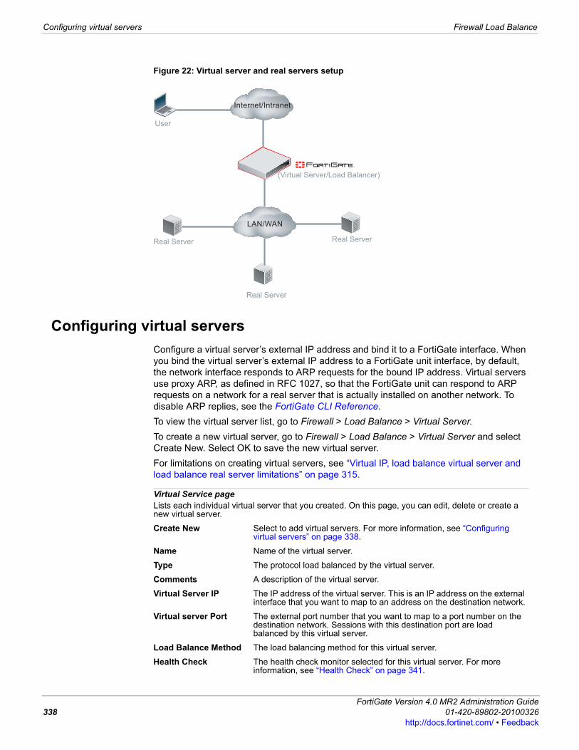
Configuring virtual servers Firewall Load Balance
Figure 22: Virtual server and real servers setup
Configuring virtual serversConfigure a virtual server’s external IP address and bind it to a FortiGate interface. When you bind the virtual server’s external IP address to a FortiGate unit interface, by default, the network interface responds to ARP requests for the bound IP address. Virtual servers use proxy ARP, as defined in RFC 1027, so that the FortiGate unit can respond to ARP requests on a network for a real server that is actually installed on another network. To disable ARP replies, see the FortiGate CLI Reference.To view the virtual server list, go to Firewall > Load Balance > Virtual Server. To create a new virtual server, go to Firewall > Load Balance > Virtual Server and select Create New. Select OK to save the new virtual server. For limitations on creating virtual servers, see “Virtual IP, load balance virtual server and load balance real server limitations” on page 315.
User
(Virtual Server/Load Balancer)
Real Server Real Server
Internet/Intranet
Real Server
LAN/WAN
Virtual Service pageLists each individual virtual server that you created. On this page, you can edit, delete or create a new virtual server.
Create New Select to add virtual servers. For more information, see “Configuring virtual servers” on page 338.
Name Name of the virtual server.
Type The protocol load balanced by the virtual server.
Comments A description of the virtual server.
Virtual Server IP The IP address of the virtual server. This is an IP address on the external interface that you want to map to an address on the destination network.
Virtual server Port The external port number that you want to map to a port number on the destination network. Sessions with this destination port are load balanced by this virtual server.
Load Balance Method The load balancing method for this virtual server.
Health Check The health check monitor selected for this virtual server. For more information, see “Health Check” on page 341.
FortiGate Version 4.0 MR2 Administration Guide338 01-420-89802-20100326
http://docs.fortinet.com/ • Feedback
Firewall Load Balance Configuring virtual servers
F0h
Persistence The type of persistence applied to this virtual server.
Delete Remove the virtual server from the list. The Delete icon only appears if the virtual server is not bound to a real server.
Edit Edit the virtual server to change any virtual server option including the virtual server name.
New Virtual Server pageProvides settings for configuring a virtual server.
Name Enter the name for the virtual server. This name is not the hostname for the FortiGate unit.
Type Select the protocol to be load balanced by the virtual server. If you select a general protocol such as IP, TCP, or UDP the virtual server load balances all IP, TCP, or UDP sessions. If you select specific protocols such as HTTP, HTTPS, or SSL you can apply additional server load balancing features such as Persistence and HTTP Multiplexing.
• Select HTTP to load balance only HTTP sessions with destination port number that matches the Virtual Server Port setting. Change Virtual Server Port to match the destination port of the sessions to be load balanced (usually port 80 for HTTP sessions). You can also select HTTP Multiplex. You can also set Persistence to HTTP Cookie to select cookie-based persistence. See the description of the config firewall VIP command in the FortiGate CLI Reference for information about advanced HTTP Cookie persistence options.
• Select HTTPS to load balance only HTTPS sessions with destination port number that matches the Virtual Server Port setting. Change Virtual Server Port to match the destination port of the sessions to be load balanced (usually port 443 for HTTPS sessions). You can also select HTTP Multiplex. You can also set Persistence to HTTP Cookie to select cookie-based persistence. You can also set Persistence to SSL Session ID. See the description of the config firewall VIP command in the FortiGate CLI Reference for information about advanced HTTP Cookie persistence options and advanced SSL options. HTTPS is available on FortiGate units that support SSL acceleration.
• Select IP to load balance all sessions accepted by the firewall policy that contains this virtual server.
• Select SSL to load balance only SSL sessions with destination port number that matches the Virtual Server Port setting. Change Virtual Server Port to match the destination port of the sessions to be load balanced. See the description of the config firewall VIP command in the FortiGate CLI Reference for information about advanced SSL options.
• Select TCP to load balance only TCP sessions with destination port number that matches the Virtual Server Port setting. Change Virtual Server Port to match the destination port of the sessions to be load balanced.
• Select UDP to load balance only UDP sessions with destination port number that matches the Virtual Server Port setting. Change Virtual Server Port to match the destination port of the sessions to be load balanced.
Interface Select the virtual server external interface from the list. The external interface is connected to the source network and receives the packets to be forwarded to the destination network.
Virtual Server IP The IP address of the virtual server. This is an IP address on the external interface that you want to map to an address on the destination network.
Virtual server Port Enter the external port number that you want to map to a port number on the destination network. Sessions with this destination port are load balanced by this virtual server.
Load Balance Method Load balancing methods include:
ortiGate Version 4.0 MR2 Administration Guide1-420-89802-20100326 339ttp://docs.fortinet.com/ • Feedback
Configuring virtual servers Firewall Load Balance
• Static: The traffic load is spread evenly across all servers, no additional server is required. This load balancing method provides some persistence because all sessions from the same source address always go to the same server. However, the distribution is stateless, so if a real server is added or removed (or goes up or down) the distribution is changed so persistence will be lost. Separate real servers are not required.
• Round Robin: Directs requests to the next server, and treats all servers as equals regardless of response time or number of connections. Dead servers or non responsive servers are avoided. A separate server is required.
• Weighted: Servers with a higher weight value will receive a larger percentage of connections. Set the server weight when adding a server.
• First Alive: Always directs requests to the first alive real server. In this case “first” refers to the order of the real servers in the virtual server configuration. For example, if you add real servers A, B and C in that order, then traffic always go to A as long as it is alive. If A goes down then traffic goes to B and if B goes down the traffic goes to C. If A comes back up traffic goes to A. Real servers are ordered in the virtual server configuration in the order in which you add them, with the most recently added real server last. If you want to change the order you must delete and re-add real servers as required.
• Least RTT: Directs requests to the server with the least round trip time. The round trip time is determined by a Ping health check monitor and is defaulted to 0 if no Ping health check monitors are added to the virtual server.
• Least Session: Directs requests to the server that has the least number of current connections. This method works best in environments where the servers or other equipment you are load balancing have similar capabilities.
Persistence Configure persistence to make sure that a user is connected to the same server every time they make a request that is part of the same session. When you configure persistence, the FortiGate unit load balances a new session to a real server according to the Load Balance Method. If the session has an HTTP cookie or an SSL session ID, the FortiGate unit sends all subsequent sessions with the same HTTP cookie or SSL session ID to the same real server.You can configure persistence if Type is set to HTTP, HTTPS, or SSL.
• Select None for no persistence. Sessions are distributed solely according to the Load Balance Method. Setting Load Balance Method to Static (the default) results in behavior equivalent to persistence. See the description of Load Balance Method for more information.
• Select HTTP Cookie so that all HTTP or HTTPS sessions with the same HTTP session cookie are sent to the same real server. HTTP Cookie is available if Type is set to HTTP or HTTPS. See the description of the config firewall VIP command in the FortiGate CLI Reference for information about advanced HTTP Cookie persistence options.
• Select SSL Session ID so that all sessions with the same SSL session ID are sent to the same real server. SSL Session ID is available if Type is set to HTTPS or SSL.
Note: The Static load balancing method provides persistence as long as the number of real servers does not change.
FortiGate Version 4.0 MR2 Administration Guide340 01-420-89802-20100326
http://docs.fortinet.com/ • Feedback
Firewall Load Balance Configuring real servers
F0h
Configuring real serversConfigure a real server to bind it to a virtual server.To view the real server list, go to Firewall > Load Balance > Real Server.For limitations on creating real servers, see “Virtual IP, load balance virtual server and load balance real server limitations” on page 315.
HTTP Multiplexing Select to use the FortiGate unit to multiplex multiple client connections into a few connections between the FortiGate unit and the real server. This can improve performance by reducing server overhead associated with establishing multiple connections. The server must be HTTP/1.1 compliant.This option appears only if HTTP or HTTS are selected for Type.Note: Additional HTTP Multiplexing options are available in the CLI. For more information, see the FortiGate CLI Reference.
Preserve Client IP Select to preserve the IP address of the client in the X-Forwarded-For HTTP header. This can be useful if you want log messages on the real servers to the client’s original IP address. If this option is not selected, the header will contain the IP address of the FortiGate unit.This option appears only if HTTP or HTTS are selected for Type, and is available only if HTTP Multiplexing is selected.
SSL Offloading Select to accelerate clients’ SSL connections to the server by using the FortiGate unit to perform SSL operations, then select which segments of the connection will receive SSL offloading.
• Client <-> FortiGateSelect to apply hardware accelerated SSL only to the part of the connection between the client and the FortiGate unit. The segment between the FortiGate unit and the server will use clear text communications. This results in best performance, but cannot be used in failover configurations where the failover path does not have an SSL accelerator.
• Client <-> FortiGate <-> ServerSelect to apply hardware accelerated SSL to both parts of the connection: the segment between client and the FortiGate unit, and the segment between the FortiGate unit and the server. The segment between the FortiGate unit and the server will use encrypted communications, but the handshakes will be abbreviated. This results in performance which is less than the other option, but still improved over communications without SSL acceleration, and can be used in failover configurations where the failover path does not have an SSL accelerator. If the server is already configured to use SSL, this also enables SSL acceleration without requiring changes to the server’s configuration.
SSL 3.0 and TLS 1.0 are supported.SSL Offloading appears only if HTTPS or SSL are selected for Type, and only on FortiGate models with hardware that supports SSL acceleration.Note: Additional SSL Offloading options are available in the CLI. For more information, see the FortiGate CLI Reference.
Certificate Select the certificate to use with SSL Offloading. The certificate key size must be 1024 or 2048 bits. 4096-bit keys are not supported.This option appears only if HTTPS or SSL are selected for Type, and is available only if SSL Offloading is selected.
Health Check Select which health check monitor configuration will be used to determine a server’s connectivity status. For information on configuring health check monitors, see “Configuring health check monitors” on page 342.
Comments Any comments or notes about this virtual server.
ortiGate Version 4.0 MR2 Administration Guide1-420-89802-20100326 341ttp://docs.fortinet.com/ • Feedback
Configuring health check monitors Firewall Load Balance
Configuring health check monitorsYou can specify which health check monitor configuration to use when polling to determine a virtual server’s connectivity status.Health check monitor configurations can specify TCP, HTTP or ICMP PING. A health check occurs every number of seconds indicated by the interval. If a reply is not received within the timeout period, and you have configured the health check to retry, it will attempt a health check again; otherwise, the virtual server is deemed unresponsive, and load balancing will compensate by disabling traffic to that server until it becomes responsive again.To create a health check monitor configuration, go to Firewall > Load Balance > Health Check Monitor and select Create New.
Real Server pageLists each individual real server that you created. On this page, you can edit, delete or create a new real server.
Create New Select to add real servers. For more information, see “Configuring real servers” on page 341.
IP Address Select the blue arrow beside a virtual server name to view the IP addresses of the real servers that are bound to it.
Port The port number on the destination network to which the external port number is mapped.
Weight The weight value of the real server. The higher the weight value, the higher the percentage of connections the server will handle.
Max Connections The limit on the number of active connections directed to a real server. If the maximum number of connections is reached for the real server, the FortiGate unit will automatically switch all further connection requests to another server until the connection number drops below the specified limit.
Delete Remove the real server from the list.
Edit Edit the real server to change any virtual server option.
New Real Server pageProvides settings for configuring a real server to bind it with a virtual one.
Virtual Server Select the virtual server to which you want to bind this real server.
IP Enter the IP address of the real server.
Port Enter the port number on the destination network to which the external port number is mapped.
Weight Enter the weight value of the real server. The higher the weight value, the higher the percentage of connections the server will handle. A range of 1-255 can be used. This option is available only if the associated virtual server’s load balance method is Weighted.
Maximum Connections Enter the limit on the number of active connections directed to a real server. A range of 1-99999 can be used. If the maximum number of connections is reached for the real server, the FortiGate unit will automatically switch all further connection requests to another server until the connection number drops below the specified limit. Setting Maximum Connections to 0 means that the FortiGate unit does not limit the number of connections to the real server.
Mode Select a mode for the real server.
FortiGate Version 4.0 MR2 Administration Guide342 01-420-89802-20100326
http://docs.fortinet.com/ • Feedback
Firewall Load Balance Configuring health check monitors
F0h
Health Check Monitor pageLists each individual health check monitor that you created. On this page, you can edit, delete and create a new health check monitor.
Create New Select to add a health check monitor configuration.
Name The name of the health check monitor configuration. The names are grouped by the health check monitor types.
Details The details of the health check monitor configuration, which vary by the type of the health check monitor, and do not include the interval, timeout, or retry, which are settings common to all types.This field is empty if the type of the health check monitor is PING.
Delete Select to remove the health check monitor configuration. This option appears only if the health check monitor configuration is not currently being used by a virtual server configuration.
Edit Select to change the health check monitor configuration.
Add New Health Check MonitorProvides settings for configuring a health check monitor.
Name Enter the name of the health check monitor configuration.
Type Select the protocol used to perform the health check.• TCP• HTTP• PING
Port Enter the port number used to perform the health check. If you set the Port to 0, the health check monitor uses the port defined in the real server. This way you can use a single health check monitor for different real servers.This option does not appear if the Type is PING.
Interval Enter the number of seconds between each server health check.
URL For HTTP health check monitors, add a URL that the FortiGate unit uses when sending a get request to check the health of a HTTP server. The URL should match an actual URL for the real HTTP servers. The URL is optional.The URL would not usually include an IP address or domain name. Instead it should start with a “/” and be followed by the address of an actual web page on the real server. For example, if the IP address of the real server is 10.10.10.1, the URL “/test_page.htm” causes the FortiGate unit to send an HTTP get request to “http://10.10.10.1/test_page.htm”.This option appears only if Type is HTTP.
Matched Content For HTTP health check monitors, add a phrase that a real HTTP server should include in response to the get request sent by the FortiGate unit using the content of the URL option. If the URL returns a web page, the Matched Content should exactly match some of the text on the web page. You can use the URL and Matched Content options to verify that an HTTP server is actually operating correctly by responding to get requests with expected web pages. Matched content is only required if you add a URL.For example, you can set Matched Content to “server test page” if the real HTTP server page defined by the URL option contains the phrase “server test page”. When the FortiGate unit receives the web page in response to the URL get request, the system searches the content of the web page for the Matched Content phrase.This option appears only if Type is HTTP.
Timeout Enter the number of seconds which must pass after the server health check to indicate a failed health check.
Retry Enter the number of times, if any, a failed health check will be retried before the server is determined to be inaccessible.
ortiGate Version 4.0 MR2 Administration Guide1-420-89802-20100326 343ttp://docs.fortinet.com/ • Feedback
Monitoring the servers Firewall Load Balance
Monitoring the serversYou can monitor the status of each virtual server and real server and start or stop the real servers.
Load balancing examplesThis section includes the following examples:• Configuring a virtual web server with three real web servers• Adding a server load balance port forwarding virtual IP• Weighted load balancing configuration• HTTP and HTTPS persistence configuration
Configuring a virtual web server with three real web serversIn this example, the virtual web server IP address 192.168.37.4 on the Internet, is mapped to three real web servers connected to the FortiGate unit dmz1 interface. The real servers have IP addresses 10.10.123.42, 10.10.123.43, and 10.10.123.44. The virtual server uses the First Alive load balancing method. The configuration also includes an HTTP health check monitor that includes a URL used by the FortiGate unit for get requests to monitor the health of the real servers.Connections to the virtual web server at IP address 192.168.37.4 from the Internet are translated and load balanced to the real servers by the FortiGate unit. First alive load balancing directs all sessions to the first real server. The computers on the Internet are unaware of this translation and load balancing and see a single virtual server at IP address 192.168.37.4 rather than the three real servers behind the FortiGate unit.
Monitor pageLists each individual server and real server that is currently being monitored by the FortiGate unit.
Virtual Server The IP addresses of the existing virtual servers.
Real Server The IP addresses of the existing real servers.
Health Status Display the health status according to the health check results for each real server. A green arrow means the server is up. A red arrow means the server is down.
Monitor Events Display each real server's up and down times.
Active Sessions Display each real server's active sessions.
RTT (ms) Display the Round Trip Time of each real server. By default, the RTT is “<1". This value will change only when ping monitoring is enabled on a real server.
Bytes Processed Display the traffic processed by each real server.
Graceful Stop/Start
Select to start or stop real servers. When stopping a server, the FortiGate unit will not accept new sessions but will wait for the active sessions to finish.
FortiGate Version 4.0 MR2 Administration Guide344 01-420-89802-20100326
http://docs.fortinet.com/ • Feedback
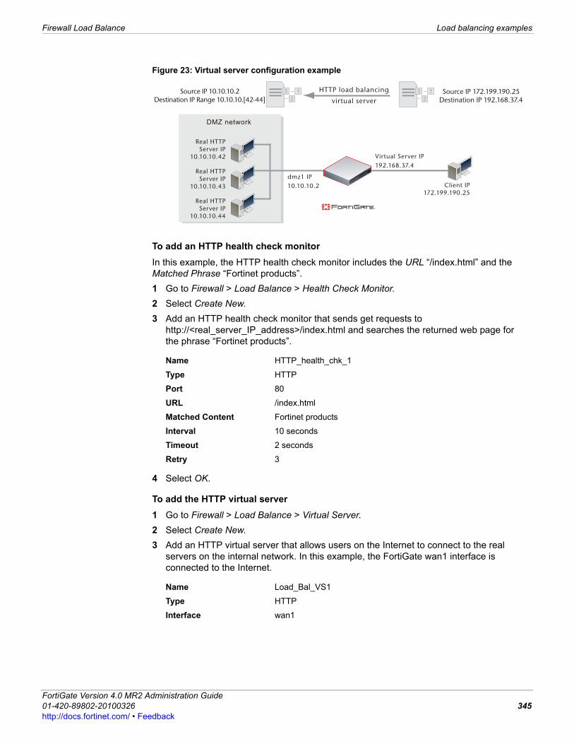
Firewall Load Balance Load balancing examples
F0h
Figure 23: Virtual server configuration example
To add an HTTP health check monitorIn this example, the HTTP health check monitor includes the URL “/index.html” and the Matched Phrase “Fortinet products”. 1 Go to Firewall > Load Balance > Health Check Monitor.2 Select Create New.3 Add an HTTP health check monitor that sends get requests to
http://<real_server_IP_address>/index.html and searches the returned web page for the phrase “Fortinet products”.
4 Select OK.
To add the HTTP virtual server1 Go to Firewall > Load Balance > Virtual Server.2 Select Create New.3 Add an HTTP virtual server that allows users on the Internet to connect to the real
servers on the internal network. In this example, the FortiGate wan1 interface is connected to the Internet.
Name HTTP_health_chk_1
Type HTTP
Port 80
URL /index.html
Matched Content Fortinet products
Interval 10 seconds
Timeout 2 seconds
Retry 3
Name Load_Bal_VS1
Type HTTP
Interface wan1
dmz1 IP10.10.10.2
HTTP load balancing
virtual serverSource IP 172.199.190.25
Destination IP 192.168.37.4Source IP 10.10.10.2
Destination IP Range 10.10.10.[42-44]
Virtual Server IP192.168.37.4
Client IP172.199.190.25
DMZ network
Real HTTPServer IP
10.10.10.42
Real HTTPServer IP
10.10.10.43
Real HTTPServer IP
10.10.10.44
3 1
2
3 1
2
ortiGate Version 4.0 MR2 Administration Guide1-420-89802-20100326 345ttp://docs.fortinet.com/ • Feedback
Load balancing examples Firewall Load Balance
4 Select OK.
To add the real servers and associate them with the virtual server1 Go to Firewall > Load Balance > Real Server.2 Select Create New.3 Configure three real servers that include the virtual server Load_Bal_VS1. Each real
server must include the IP address of a real server on the internal network.Configuration for the first real server.
Configuration for the second real server.
Virtual Server IP 192.168.37.4 The public IP address of the web server. The virtual server IP address is usually a static IP address obtained from your ISP for your web server. This address must be a unique IP address that is not used by another host and cannot be the same as the IP address of the external interface the virtual IP will be using. However, the external IP address must be routed to the selected interface. The virtual IP address and the external IP address can be on different subnets. When you add the virtual IP, the external interface responds to ARP requests for the external IP address.
Virtual Server Port 80
Load Balance Method First Alive
Persistence HTTP cookie
HTTP Multiplexing Select.The FortiGate unit multiplexes multiple client into a few connections between the FortiGate unit and a real HTTP server. This can improve performance by reducing server overhead associated with establishing multiple connections.
Preserve Client IP SelectThe FortiGate unit preserves the IP address of the client in the X-Forwarded-For HTTP header.
Health Check Move the HTTP_health_chk_1 health check monitor to the Selected list.
Virtual Server Load_Bal_VS1
IP 10.10.10.42
Port 80
Weight Cannot be configured because the virtual server does not include weighted load balancing.
Maximum Connections 0Setting Maximum Connections to 0 means the FortiGate unit does not limit the number of connections to the real server. Since the virtual server uses First Alive load balancing you may want to limit the number of connections to each real server to limit the traffic received by each server. In this example, the Maximum Connections is initially set to 0 but can be adjusted later if the real servers are getting too much traffic.
FortiGate Version 4.0 MR2 Administration Guide346 01-420-89802-20100326
http://docs.fortinet.com/ • Feedback
Firewall Load Balance Load balancing examples
F0h
Configuration for the third real server.
To add the virtual server to a firewall policyAdd a wan1 to dmz1 firewall policy that uses the virtual server so that when users on the Internet attempt to connect to the web server’s IP address, packets pass through the FortiGate unit from the wan1 interface to the dmz1 interface. The virtual IP translates the destination address of these packets from the virtual server IP address to the real server IP addresses.1 Go to Firewall > Policy.2 Select Create New.3 Configure the firewall policy:
4 Select other firewall options as required.5 Select OK.
Virtual Server Load_Bal_VS1
IP 10.10.10.43
Port 80
Weight Cannot be configured because the virtual server does not include weighted load balancing.
Maximum Connections 0Setting Maximum Connections to 0 means the FortiGate unit does not limit the number of connections to the real server. Since the virtual server uses First Alive load balancing you may want to limit the number of connections to each real server to limit the traffic received by each server. In this example, the Maximum Connections is initially set to 0 but can be adjusted later if the real servers are getting too much traffic.
Virtual Server Load_Bal_VS1
IP 10.10.10.44
Port 80
Weight Cannot be configured because the virtual server does not include weighted load balancing.
Maximum Connections 0Setting Maximum Connections to 0 means the FortiGate unit does not limit the number of connections to the real server. Since the virtual server uses First Alive load balancing you may want to limit the number of connections to each real server to limit the traffic received by each server. In this example, the Maximum Connections is initially set to 0 but can be adjusted later if the real servers are getting too much traffic.
Source Interface/Zone wan1
Source Address all (or a more specific address)
Destination Interface/Zone dmz1
Destination Address Load_Bal_VS1
Schedule always
Service HTTP
Action ACCEPT
NAT Select
Log Allowed Traffic Select to log virtual server traffic
ortiGate Version 4.0 MR2 Administration Guide1-420-89802-20100326 347ttp://docs.fortinet.com/ • Feedback

Load balancing examples Firewall Load Balance
Adding a server load balance port forwarding virtual IPThis example is the same as the example described in “Configuring a virtual web server with three real web servers” on page 344 except that each real server accepts HTTP connections on a different port number. The first real server accepts connections on port 8080, the second on port 8081, and the third on 8082.
Figure 24: Server load balance virtual IP port forwarding
To complete this configuration, all of the steps would be the same as in “Configuring a virtual web server with three real web servers” on page 344 except for configuring the real servers.
To add the real servers and associate them with the virtual serverUse the following steps to configure the FortiGate unit to port forward HTTP packets to the three real servers on ports 8080, 8081, and 8082.1 Go to Firewall > Load Balance > Real Server.2 Select Create New.3 Configure three real servers that include the virtual server Load_Bal_VS1. Each real
server must include the IP address of a real server on the internal network and have a different port number.Configuration for the first real server.
Configuration for the second real server.
Virtual Server Load_Bal_VS1
IP 10.10.10.42
Port 8080
Weight Cannot be configured because the virtual server does not include weighted load balancing.
Maximum Connections 0
dmz1 IP10.10.10.2
HTTP load balancing
virtual serverSource IP 172.199.190.25
Destination IP 192.168.37.4Port 80
Source IP 10.10.10.2Destination IP Range 10.10.10.[42-44]
Port Range 8080 - 8082
Virtual Server IP192.168.37.4
Client IP172.199.190.25
DMZ network
Real HTTPServer IP
10.10.10.42
Real HTTPServer IP
10.10.10.43
Real HTTPServer IP
10.10.10.44
3 1
2
3 1
2
FortiGate Version 4.0 MR2 Administration Guide348 01-420-89802-20100326
http://docs.fortinet.com/ • Feedback
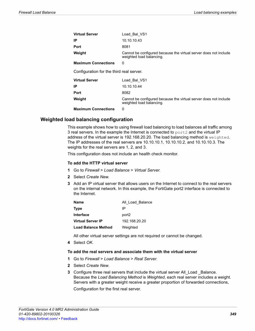
Firewall Load Balance Load balancing examples
F0h
Configuration for the third real server.
Weighted load balancing configurationThis example shows how to using firewall load balancing to load balances all traffic among 3 real servers. In the example the Internet is connected to port2 and the virtual IP address of the virtual server is 192.168.20.20. The load balancing method is weighted. The IP addresses of the real servers are 10.10.10.1, 10.10.10.2, and 10.10.10.3. The weights for the real servers are 1, 2, and 3. This configuration does not include an health check monitor.
To add the HTTP virtual server1 Go to Firewall > Load Balance > Virtual Server.2 Select Create New.3 Add an IP virtual server that allows users on the Internet to connect to the real servers
on the internal network. In this example, the FortiGate port2 interface is connected to the Internet.
All other virtual server settings are not required or cannot be changed.4 Select OK.
To add the real servers and associate them with the virtual server1 Go to Firewall > Load Balance > Real Server.2 Select Create New.3 Configure three real servers that include the virtual server All_Load _Balance.
Because the Load Balancing Method is Weighted, each real server includes a weight. Servers with a greater weight receive a greater proportion of forwarded connections,Configuration for the first real server.
Virtual Server Load_Bal_VS1
IP 10.10.10.43
Port 8081
Weight Cannot be configured because the virtual server does not include weighted load balancing.
Maximum Connections 0
Virtual Server Load_Bal_VS1
IP 10.10.10.44
Port 8082
Weight Cannot be configured because the virtual server does not include weighted load balancing.
Maximum Connections 0
Name All_Load_Balance
Type IP
Interface port2
Virtual Server IP 192.168.20.20
Load Balance Method Weighted
ortiGate Version 4.0 MR2 Administration Guide1-420-89802-20100326 349ttp://docs.fortinet.com/ • Feedback

Load balancing examples Firewall Load Balance
Configuration for the second real server.
Configuration for the third real server.
To add the virtual server to a firewall policyAdd a prot2 to port1 firewall policy that uses the virtual server so that when users on the Internet attempt to connect to the web server’s IP address, packets pass through the FortiGate unit from the wan1 interface to the dmz1 interface. The virtual IP translates the destination address of these packets from the virtual server IP address to the real server IP addresses.1 Go to Firewall > Policy.2 Select Create New.3 Configure the firewall policy:
Virtual Server All_Load_Balance
IP 10.10.10.1
Port Cannot be configured because the virtual server is an IP server.
Weight 1
Maximum Connections 0Setting Maximum Connections to 0 means the FortiGate unit does not limit the number of connections to the real server. Since the virtual server uses First Alive load balancing you may want to limit the number of connections to each real server to limit the traffic received by each server. In this example, the Maximum Connections is initially set to 0 but can be adjusted later if the real servers are getting too much traffic.
Virtual Server All_Load_Balance
IP 10.10.10.2
Port Cannot be configured because the virtual server is an IP server.
Weight 2
Maximum Connections 0Setting Maximum Connections to 0 means the FortiGate unit does not limit the number of connections to the real server. Since the virtual server uses First Alive load balancing you may want to limit the number of connections to each real server to limit the traffic received by each server. In this example, the Maximum Connections is initially set to 0 but can be adjusted later if the real servers are getting too much traffic.
Virtual Server All_Load_Balance
IP 10.10.10.3
Port Cannot be configured because the virtual server is an IP server.
Weight 3
Maximum Connections 0Setting Maximum Connections to 0 means the FortiGate unit does not limit the number of connections to the real server. Since the virtual server uses First Alive load balancing you may want to limit the number of connections to each real server to limit the traffic received by each server. In this example, the Maximum Connections is initially set to 0 but can be adjusted later if the real servers are getting too much traffic.
FortiGate Version 4.0 MR2 Administration Guide350 01-420-89802-20100326
http://docs.fortinet.com/ • Feedback
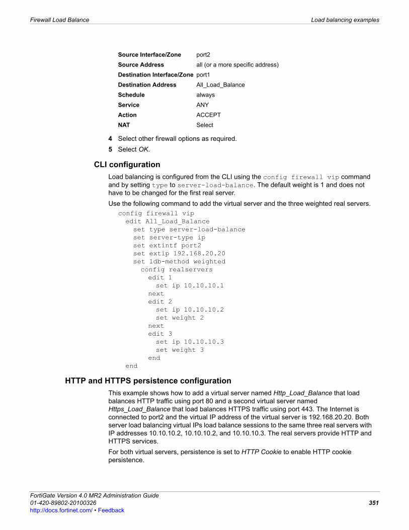
Firewall Load Balance Load balancing examples
F0h
4 Select other firewall options as required.5 Select OK.
CLI configurationLoad balancing is configured from the CLI using the config firewall vip command and by setting type to server-load-balance. The default weight is 1 and does not have to be changed for the first real server.Use the following command to add the virtual server and the three weighted real servers.
config firewall vipedit All_Load_Balanceset type server-load-balanceset server-type ipset extintf port2set extip 192.168.20.20set ldb-method weightedconfig realserversedit 1set ip 10.10.10.1
nextedit 2set ip 10.10.10.2set weight 2
nextedit 3set ip 10.10.10.3set weight 3
endend
HTTP and HTTPS persistence configurationThis example shows how to add a virtual server named Http_Load_Balance that load balances HTTP traffic using port 80 and a second virtual server named Https_Load_Balance that load balances HTTPS traffic using port 443. The Internet is connected to port2 and the virtual IP address of the virtual server is 192.168.20.20. Both server load balancing virtual IPs load balance sessions to the same three real servers with IP addresses 10.10.10.2, 10.10.10.2, and 10.10.10.3. The real servers provide HTTP and HTTPS services. For both virtual servers, persistence is set to HTTP Cookie to enable HTTP cookie persistence.
Source Interface/Zone port2
Source Address all (or a more specific address)
Destination Interface/Zone port1
Destination Address All_Load_Balance
Schedule always
Service ANY
Action ACCEPT
NAT Select
ortiGate Version 4.0 MR2 Administration Guide1-420-89802-20100326 351ttp://docs.fortinet.com/ • Feedback
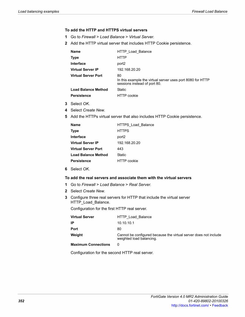
Load balancing examples Firewall Load Balance
To add the HTTP and HTTPS virtual servers1 Go to Firewall > Load Balance > Virtual Server.2 Add the HTTP virtual server that includes HTTP Cookie persistence.
3 Select OK.4 Select Create New.5 Add the HTTPs virtual server that also includes HTTP Cookie persistence.
6 Select OK.
To add the real servers and associate them with the virtual servers1 Go to Firewall > Load Balance > Real Server.2 Select Create New.3 Configure three real servers for HTTP that include the virtual server
HTTP_Load_Balance.Configuration for the first HTTP real server.
Configuration for the second HTTP real server.
Name HTTP_Load_Balance
Type HTTP
Interface port2
Virtual Server IP 192.168.20.20
Virtual Server Port 80In this example the virtual server uses port 8080 for HTTP sessions instead of port 80.
Load Balance Method Static
Persistence HTTP cookie
Name HTTPS_Load_Balance
Type HTTPS
Interface port2
Virtual Server IP 192.168.20.20
Virtual Server Port 443
Load Balance Method Static
Persistence HTTP cookie
Virtual Server HTTP_Load_Balance
IP 10.10.10.1
Port 80
Weight Cannot be configured because the virtual server does not include weighted load balancing.
Maximum Connections 0
FortiGate Version 4.0 MR2 Administration Guide352 01-420-89802-20100326
http://docs.fortinet.com/ • Feedback
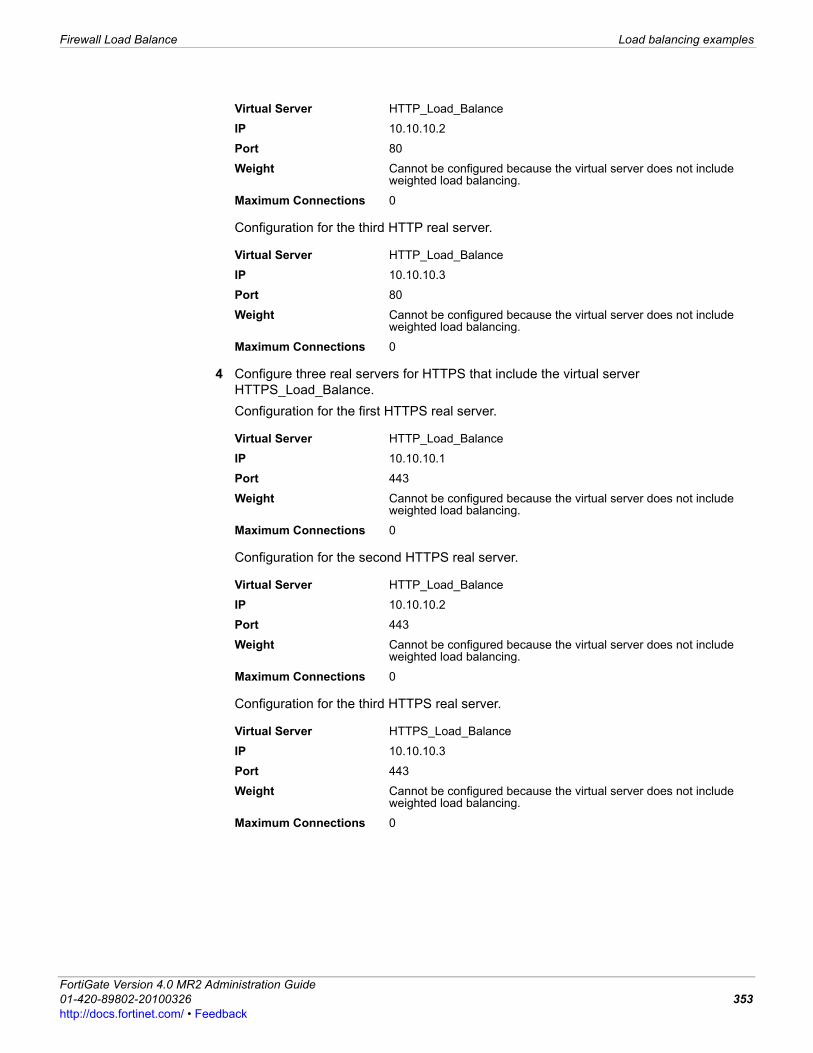
Firewall Load Balance Load balancing examples
F0h
Configuration for the third HTTP real server.
4 Configure three real servers for HTTPS that include the virtual server HTTPS_Load_Balance.Configuration for the first HTTPS real server.
Configuration for the second HTTPS real server.
Configuration for the third HTTPS real server.
Virtual Server HTTP_Load_Balance
IP 10.10.10.2
Port 80
Weight Cannot be configured because the virtual server does not include weighted load balancing.
Maximum Connections 0
Virtual Server HTTP_Load_Balance
IP 10.10.10.3
Port 80
Weight Cannot be configured because the virtual server does not include weighted load balancing.
Maximum Connections 0
Virtual Server HTTP_Load_Balance
IP 10.10.10.1
Port 443
Weight Cannot be configured because the virtual server does not include weighted load balancing.
Maximum Connections 0
Virtual Server HTTP_Load_Balance
IP 10.10.10.2
Port 443
Weight Cannot be configured because the virtual server does not include weighted load balancing.
Maximum Connections 0
Virtual Server HTTPS_Load_Balance
IP 10.10.10.3
Port 443
Weight Cannot be configured because the virtual server does not include weighted load balancing.
Maximum Connections 0
ortiGate Version 4.0 MR2 Administration Guide1-420-89802-20100326 353ttp://docs.fortinet.com/ • Feedback
Load balancing examples Firewall Load Balance
To add the virtual servers to firewall policiesAdd a port2 to port1 firewall policy that uses the virtual server so that when users on the Internet attempt to connect to the web server’s IP address, packets pass through the FortiGate unit from the wan1 interface to the dmz1 interface. The virtual IP translates the destination address of these packets from the virtual server IP address to the real server IP addresses.1 Go to Firewall > Policy.2 Select Create New.3 Configure the HTTP firewall policy:
4 Select other firewall options as required.5 Select OK.6 Select Create New.7 Configure the HTTP firewall policy:
8 Select other firewall options as required.9 Select OK.
CLI configuration: adding persistence for a specific domainLoad balancing is configured from the CLI using the config firewall vip command and by setting type to server-load-balance.For the CLI configuration, both virtual servers include setting http-cookie-domain to .example.org because HTTP cookie persistence is just required for the example.org domain.First, the configuration for the HTTP virtual IP:
config firewall vipedit HTTP_Load_Balanceset type server-load-balanceset server-type http
Source Interface/Zone port2
Source Address all
Destination Interface/Zone port1
Destination Address HTTP_Load_Balance
Schedule always
Service HTTP
Action ACCEPT
NAT Select
Source Interface/Zone port2
Source Address all
Destination Interface/Zone port1
Destination Address HTTPS_Load_Balance
Schedule always
Service HTTPS
Action ACCEPT
NAT Select
FortiGate Version 4.0 MR2 Administration Guide354 01-420-89802-20100326
http://docs.fortinet.com/ • Feedback
Firewall Load Balance Load balancing examples
F0h
set extport 8080set extintf port2set extip 192.168.20.20set persistence http-cookieset http-cookie-domain .example.orgconfig realserversedit 1set ip 10.10.10.1
nextedit 2set ip 10.10.10.2
nextedit 3set ip 10.10.10.3
endend
Second, the configuration for the HTTPS virtual IP. In this configuration you don’t have to set extport to 443 because extport is automatically set to 443 when server-type is set to https.
config firewall vipedit HTTPS_Load_Balanceset type server-load-balanceset server-type httpsset extport 443set extintf port2set extip 192.168.20.20set persistence http-cookieset http-cookie-domain .example.orgconfig realserversedit 1set ip 10.10.10.1
nextedit 2set ip 10.10.10.2
nextedit 3set ip 10.10.10.3
endend
ortiGate Version 4.0 MR2 Administration Guide1-420-89802-20100326 355ttp://docs.fortinet.com/ • Feedback

Load balancing examples Firewall Load Balance
FortiGate Version 4.0 MR2 Administration Guide356 01-420-89802-20100326
http://docs.fortinet.com/ • Feedback

UTM UTM overview
F0h
UTM This section provides an introduction to the UTM menu. For more information about the UTM menu, such as how to configure antivirus settings, see the UTM chapter of the FortiOS Handbook. The following topics are included in this section: • UTM overview• AntiVirus• Intrusion Protection• Web Filter• Email Filter• Data Leak Prevention• Application Control• VoIP
UTM overviewThe UTM menu provides a number of security features, such as antivirus or DoS sensors. This menu also includes profiles, which are applied to firewall policies. A profile is specific information that defines how the traffic within a policy is examined and what action is taken based on the examination. The UTM menu contains the following seven features, and some of these features contain profiles which you can then apply to firewall policies: • Antivirus – provides configuration settings for filtering and scanning viruses, as well as
quarantine settings. This feature also contains settings for choosing an antivirus database that is suited to your network requirements. Profiles are available.
• Intrusion Protection – provides configuration settings for IPS sensors and DoS sensors, including creating customized signatures. You can also view detailed information about the predefined signatures. Default protocol decoders are available to view as well.
• Web filter – provides configuration settings for filtering web content, as well as enabling FortiGuard web filter and FortiGuard web filtering overrides. This feature also includes URL filter, override, local categories, and local ratings configuration settings. Profiles are available.
• Email filtering – also known as anti-spam, provides configuration settings for filtering and scanning banned words, IP addresses, and email addresses. Profiles are available.
• Data Leak Prevention (DLP) – provides configuration settings for creating DLP sensors, compound rules and rules. Instead of profiles, DLP sensors are applied to firewall policies.
• Application Control – provides configuration settings for creating application control black/white lists. You can also view detailed information about applications from the list of applications on the Application List page.
ortiGate Version 4.0 MR2 Administration Guide1-420-89802-20100326 357ttp://docs.fortinet.com/ • Feedback
AntiVirus UTM
• VoIP – provides configuration settings for creating a profile, which you can then apply to a firewall policy. This profile also includes enabling logging of SIP and SCCP traffic as well as traffic violations.
AntiVirusThe following explains the antivirus options that you can configure in the Antivirus menu. When configuring a profile, you can apply an antivirus profile to a firewall policy for HTTP, FTP, IMAP, POP3, SMTP, IM, and NNTP sessions. If your FortiGate unit supports SSL content scanning and inspection you can also configure antivirus protection for HTTPS, IMAPS, POP3S, and SMTPS sessions. For more information, see the UTM chapter of the FortiOS Handbook. If you enable virtual domains (VDOMs) on the FortiGate unit, antivirus options are configured separately for each virtual domain. For more information, see “Using virtual domains” on page 73.This topic includes the following:• Profile• File Filter• Quarantine• Quarantine configuration• Virus Database
ProfileThe Profile page allows you to configure antivirus profiles for applying to firewall policies. A profile is specific information that defines how the traffic within a policy is examined and what action may be taken based on the examination. You can create multiple antivirus profiles for different antivirus scanning requirements. For example, you create an antivirus profile that specifies only virus scanning for POP3 which you then apply to the out-going firewall policy. Antivirus profiles are configured in UTM > Antivirus > Profile.
Profile pageLists each individual antivirus profile that you created. On this page, you can edit, delete or create a new antivirus profile.
Create New When you select Create New, you are automatically redirected to the New Antivirus Profile page.
Edit Select to modify settings to an antivirus profile.
Delete Select to remove an antivirus profile.
Name The name of the antivirus profile.
Comments A description for the antivirus profile.
New Antivirus Profile pageProvides settings for configuring a new antivirus profile. This page also allows you to configure quarantine settings for including a virus sender to the Banned User List. If you are editing an existing antivirus profile, you are redirected to the Edit Antivirus Profile page, which contains the same settings as in the New Antivirus Profile page.
Name Enter a name for the profile. If you are editing an existing antivirus profile and want to change the name, enter a new name in this field. You must select OK to save these changes.
FortiGate Version 4.0 MR2 Administration Guide358 01-420-89802-20100326
http://docs.fortinet.com/ • Feedback
UTM AntiVirus
F0h
File FilterThe Filter menu allows you to configure filtering options that block specific file patterns and file types. Files are compared to the enabled file patterns and then the file types from top to bottom. If a file does not match any specified patterns or types, it is passed along to antivirus scanning (if enabled). In effect, files are passed if not explicitly blocked. The FortiGate unit also writes a message to the virus log and sends an alert email message if configured to do so.The FortiGate unit can take either of these actions toward files that match a configured file pattern or type:• Allow: the file is allowed to pass. • Block: the file is blocked and a replacement messages will be sent to the user. If both
file filter and virus scan are enabled, the FortiGate unit blocks files that match the enabled file filter and does not scan these files for viruses.
• Intercept: the file will be archived to the local hard disk or the FortiAnalyzer unit.
Comment Enter a description for the profile; this is optional. If you are editing an existing antivirus profile and want to change the description, enter the changes in this field. You must select OK to save the changes.
Virus Scan Select any of the following to have the FortiGate unit scan for viruses when these protocols are used: • HTTP• FTP• IMAP• POP3• SMTP• NNTPSelect the Logging check box if you want logs for these events.
File Filter Select any of the following to have the FortiGate unit scan using a file filter list when these protocols are used: • HTTP• FTP• IMAP• POP3• SMTP• NNTPSelect a filter from the list from the Options drop-down list.
Quarantine Virus Sender (to Banned Users List)
Select to enable and configure the sender quarantine. The sender who sent the virus will be put in the Banned Users List.
Method Appears when Quarantine Virus Sender (to Banned Users List) is selected. Select Source IP address to block all traffic sent from the attackers IP address. The attackers IP address is also added to the banned user list. The target address is not affected. Select Virus’s Incoming Interface to block all traffic from connecting to the FortiGate interface that received the attack. The interface is added to the banned user list.
Expires Appears when Quarantine Virus Sender (to Banned Users List) is selected. You can select whether the virus is banned indefinitely or for a specified number of days, hours, or minutes.
ortiGate Version 4.0 MR2 Administration Guide1-420-89802-20100326 359ttp://docs.fortinet.com/ • Feedback
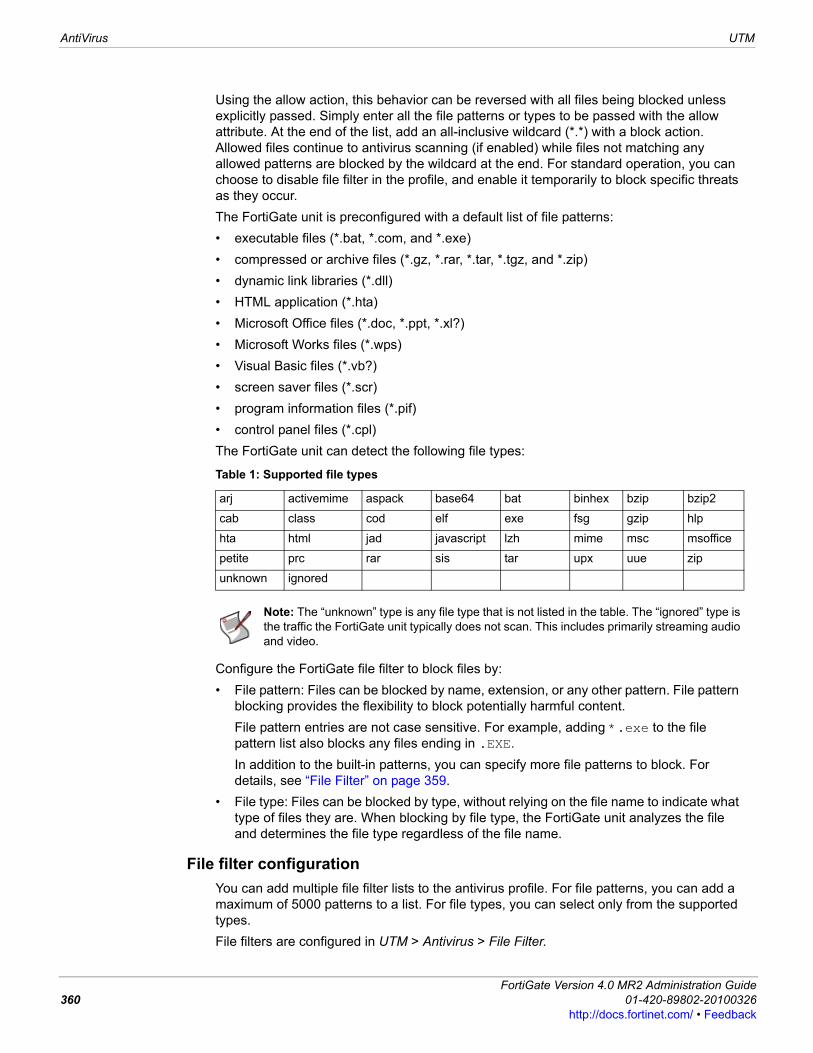
AntiVirus UTM
Using the allow action, this behavior can be reversed with all files being blocked unless explicitly passed. Simply enter all the file patterns or types to be passed with the allow attribute. At the end of the list, add an all-inclusive wildcard (*.*) with a block action. Allowed files continue to antivirus scanning (if enabled) while files not matching any allowed patterns are blocked by the wildcard at the end. For standard operation, you can choose to disable file filter in the profile, and enable it temporarily to block specific threats as they occur.The FortiGate unit is preconfigured with a default list of file patterns:• executable files (*.bat, *.com, and *.exe)• compressed or archive files (*.gz, *.rar, *.tar, *.tgz, and *.zip)• dynamic link libraries (*.dll)• HTML application (*.hta)• Microsoft Office files (*.doc, *.ppt, *.xl?)• Microsoft Works files (*.wps)• Visual Basic files (*.vb?)• screen saver files (*.scr)• program information files (*.pif)• control panel files (*.cpl)The FortiGate unit can detect the following file types:
Configure the FortiGate file filter to block files by:• File pattern: Files can be blocked by name, extension, or any other pattern. File pattern
blocking provides the flexibility to block potentially harmful content. File pattern entries are not case sensitive. For example, adding *.exe to the file pattern list also blocks any files ending in .EXE.In addition to the built-in patterns, you can specify more file patterns to block. For details, see “File Filter” on page 359.
• File type: Files can be blocked by type, without relying on the file name to indicate what type of files they are. When blocking by file type, the FortiGate unit analyzes the file and determines the file type regardless of the file name.
File filter configurationYou can add multiple file filter lists to the antivirus profile. For file patterns, you can add a maximum of 5000 patterns to a list. For file types, you can select only from the supported types. File filters are configured in UTM > Antivirus > File Filter.
Table 1: Supported file types
arj activemime aspack base64 bat binhex bzip bzip2
cab class cod elf exe fsg gzip hlp
hta html jad javascript lzh mime msc msoffice
petite prc rar sis tar upx uue zip
unknown ignored
Note: The “unknown” type is any file type that is not listed in the table. The “ignored” type is the traffic the FortiGate unit typically does not scan. This includes primarily streaming audio and video.
FortiGate Version 4.0 MR2 Administration Guide360 01-420-89802-20100326
http://docs.fortinet.com/ • Feedback
UTM AntiVirus
F0h
File Filter page Lists each individual file filter that you created. On this page, you can edit, delete or create a new file filter.
Create New Select Create New to add a new file filter list to the catalog.
Name The available file filter lists.
# Entries The number of file patterns or file types in each file filter list.
DLP Rule The DLP rules in which each filter is used.
Comments An optional description of each file filter list.
Delete Select to remove the file filter list from the catalog.
Edit Select to edit the file filter.
File Filter Settings pageProvides settings for configuring multiple file patterns and file types that make up a file filter. This page also lists the file patterns and file types that were created for the file filter. If you are editing a file filter, you are redirected to this page.
Name File filter name. To change the name, edit the text in the name field and select OK.
Comment Optional comment. To add or edit comment, enter text in comment field and select OK.
OK If you make changes to the list name or comments, select OK to save the changes.
Create New Select Create New to add a new file pattern or type to the file filter list.
Disable Select to disable a file pattern or type.
Delete Select to remove the file pattern or type from the list.
Edit Select to edit the file pattern/type and action.
Move Select to move the file pattern or type to any position in the list.
Filter The current list of file patterns and types.
Action Files matching the file patterns and types can be set to Block or Allow. For information about actions, see “File Filter” on page 359.
Enable Clear the checkbox to disable the file pattern or type.
New File Filter pageFilter Type Select File Name Pattern or File Type.
File Type Select a file type from the list. Appears only when File Type is selected in Filter Type.
Pattern Enter the file pattern. The file pattern can be an exact file name or can include wildcards. The file pattern can be 80 characters long.
Action Select an action from the drop down list: Block or Allow. For more information about actions, see “File Filter” on page 359.
Enable Select to enable or disable the filter.
Note: The default file pattern list catalog is called builtin-patterns.
ortiGate Version 4.0 MR2 Administration Guide1-420-89802-20100326 361ttp://docs.fortinet.com/ • Feedback
AntiVirus UTM
QuarantineFortiGate units with a local disk can quarantine blocked and infected files. Detailed information about the file is found in the log file, which is available for viewing in Log&Report > Archive Access > Quarantine. Submit specific files and add file patterns to the AutoSubmit list so they will automatically be uploaded to Fortinet for analysis.FortiGate units can also quarantine blocked and infected files to a FortiAnalyzer unit, which are also available to view in Log&Report > Archive Access > Quarantine.
Quarantine configurationYou can configure quarantine options for HTTP, FTP, IMAP, POP3, SMTP, MM1, MM3, MM4, MM7, IM, and NNTP traffic. If your FortiGate unit supports SSL content scanning and inspection, you can also quarantine blocked and infected files from HTTPS, IMAPS, POP3S, and SMTPS traffic. For more information, see the UTM chapter of the FortiOS Handbook. Quarantine configuration is located in UTM > Antivirus > Quarantine.
Quarantine Configuration pageProvides settings for configuring the actions the FortiGate unit takes when infected, suspicious, and blocked files are scanned for viruses. These settings are for the local disk or FortiAnalyzer unit. You can view these settings or modify them from the Quarantine Configuration page.
Quarantine Infected Files
Select the protocols that you want the FortiGate unit to look at.
Quarantine Suspicious Files
Select the protocols that you want the FortiGate unit to look at.
Quarantine Blocked Files
Select the check boxes within the protocol columns that you want the FortiGate unit to look at.
Quarantine To Select to enable storage of blocked, suspicious and infected files to a FortiAnalyzer unit or local disk. By default, the setting is set to None; you must select FortiAnalyzer if you want to store quarantine files.
Max Filesize to Quarantine
Appears only when either the FortiAnalyzer unit or local disk is selected as the storage location for quarantine files. The maximum size of quarantined files in MB. Setting the size too large may affect performance.
Disk Age Limit (only on FortiGate models with local disks)
The time limit in hours which keeps files in quarantine. The age limit is used to formulate the value in the TTL column of the quarantined files list, located in Log&Report > Archive Access > Quarantine. When the limit is reached, the TTL column displays EXP and the file is deleted (although the entry in the quarantined files list is maintained). Entering an age limit of 0 (zero) means files are stored on the local disk indefinitely, depending on what action was chosen in Log Disk space.
Low Disk space Select the action to take when the local disk is full: overwrite the oldest file or drop the newest file.
Enable AutoSubmit (appears only on FortiGate models with local disks)
Select to enable the automatic submission feature.
Use File Pattern Select to enable the automatic upload of the files matching the file patterns in
Use File Status Select to enable the automatic upload of files matching the file patterns in the AutoSubmit list.
Heuristics Select to base the automatic upload of files on their Heuristic status.
Block Pattern Select to base the automatic upload of files on their Block Pattern status.
FortiGate Version 4.0 MR2 Administration Guide362 01-420-89802-20100326
http://docs.fortinet.com/ • Feedback
UTM AntiVirus
F0h
Virus Database The FortiGate unit contains multiple antivirus databases for you to choose from, so that you can get the maximum protection that you need for your network environment. The Virus Database, located in UTM > Antivirus > Virus Database, is used to detect viruses in network traffic. The databases are available on the Virus Database page: • Regular Virus Database • Extended Virus Database • Extreme Virus Database• Flow-based Virus Database On the Virus Database page, you can also enable grayware detection. This grayware detection includes adware, dial, downloader, hacker tool, keylogger, RAT, and spyware. The extended database provides “in the wild” viruses as well as a large collection of zoo viruses that have not yet been seen in current virus studies. An enhanced security environment is best suited for this type of database. The flow-based database provides “in the wild” viruses as well as some commonly seen viruses on the network. Flow-based virus scanning is an alternative to the file-based virus scanning, providing better performance but lower coverage rates than the file-based virus scan. The extreme antivirus database allows scanning for both “in the wild” and “zoo” viruses that are no longer seen in recent studies as well as all available signatures that are currently supported. The extreme database provides flexibility, providing the maximum protection without sacrificing performance and is suited to an enhanced security environment. The extreme antivirus database is available only on FortiGate models that have AMC-enabled platforms and large capacity hard drives. The flow-based antivirus database helps to detect malware using IPS. This database includes “in the wild” viruses along with some commonly seen viruses on the network. The flow-based antivirus database provides an alternative to the file-based virus scan while also providing better performance. The FortiGuard virus definitions are updated when the FortiGate unit receives a new version of FortiGuard antivirus definitions from the FDN.The FortiGuard Center Virus Encyclopedia contains detailed descriptions of the viruses, worms, trojans, and other threats that can be detected and removed by your FortiGate unit using the information in the FortiGuard virus definitions.The FortiGuard AV definitions are updated automatically from the FortiGuard Distribution Network (FDN). Automatic antivirus definition updates are configured from the FDN by going to System > Maintenance > FortiGuard. You can also update the antivirus definitions manually from the system dashboard by going to System > Dashboard > Status.
Note: If virtual domains are enabled, you must configure antivirus file filtering and antivirus settings in antivirus profiles separately for each virtual domain.Grayware settings can only be enabled or disabled when running FortiOS 4.0 MR2 or higher on a FortiGate unit.
ortiGate Version 4.0 MR2 Administration Guide1-420-89802-20100326 363ttp://docs.fortinet.com/ • Feedback
Intrusion Protection UTM
Intrusion ProtectionThe FortiGate Intrusion Protection system combines signature and anomaly detection and prevention with low latency and excellent reliability. With Intrusion Protection, you can create multiple IPS sensors, each containing a complete configuration based on signatures. Then, you can apply any IPS sensor to a firewall policy. You can also create DoS sensors to examine traffic for anomaly-based attacks.If you enable virtual domains (VDOMs) on the FortiGate unit, intrusion protection is configured separately for each virtual domain. For more information, see “Using virtual domains” on page 73.This topic contains the following: • IPS Sensor• DoS sensor• Predefined• Custom• Protocol Decoder
IPS SensorYou can group signatures into IPS sensors for easy selection when applying to firewall policies. You can define signatures for specific types of traffic in separate IPS sensors, and then select those sensors in profiles designed to handle that type of traffic. For example, you can specify all of the web-server related signatures in an IPS sensor, and that sensor can then be applied to a firewall policy that controls all of the traffic to and from a web server protected by the FortiGate unit.The FortiGuard Service periodically updates the pre-defined signatures, with signatures added to counter new threats. Since the signatures included in filters are defined by specifying signature attributes, new signatures matching existing filter specifications will automatically be included in those filters. For example, if you have a filter that includes all signatures for the Windows operating system, your filter will automatically incorporate new Windows signatures as they are added.Each IPS sensor consists of two parts: filters and overrides. Overrides are always checked before filters.Each filter consists of a number of signatures attributes. All of the signatures with those attributes, and only those attributes, are checked against traffic when the filter is run. If multiple filters are defined in an IPS Sensor, they are checked against the traffic one at a time, from top to bottom. If a match is found, the FortiGate unit takes the appropriate action and stops further checking.A signature override can modify the behavior of a signature specified in a filter. A signature override can also add a signature not specified in the sensor’s filters. Custom signatures are included in an IPS sensor using overrides.The signatures in the overrides are first compared to network traffic. If the IPS sensor does not find any matches, it then compares the signatures in each filter to network traffic, one filter at a time, from top to bottom. If no signature matches are found, the IPS sensor allows the network traffic.The signatures included in the filter are only those matching every attribute specified. When created, a new filter has every attribute set to all which causes every signature to be included in the filter. If the severity is changed to high, and the target is changed to server, the filter includes only signatures checking for high priority attacks targeted at servers.
FortiGate Version 4.0 MR2 Administration Guide364 01-420-89802-20100326
http://docs.fortinet.com/ • Feedback
UTM Intrusion Protection
F0h
IPS sensors are configured in UTM > Intrusion Protection > IPS Sensor.
IPS Sensor pageLists each individual IPS sensor, either default or ones that you created. On this page you can edit, delete or create a new IPS sensor.
Create New When you select Create New, you are automatically redirected to the New IPS Sensor page. This page provides a name field and comment field. You must enter a name to go the IPS Sensor Settings page.
Name The name of each IPS sensor.
Comments An optional description of the IPS sensor.
all_defaults (default)
Includes all signatures. The sensor is set to use the default enable status and action of each signature.
all_default_pass(default)
Includes all signatures. The sensor is set to use the default enable status of each signature, but the action is set to pass.
protect_client (default)
Includes only the signatures designed to detect attacks against clients and uses the default enable status and action of each signature.
protect_email_server(default)
Includes only the signatures designed to detect attacks against servers and the SMTP, POP3, or IMAP protocols and uses the default enable status and action of each signature.
protect_http_server(default)
Includes only the signatures designed to detect attacks against servers and the HTTP protocol and uses the default enable status and action of each signature.
Delete Removes the IPS sensor from the list.
Edit Edit an IPS sensor.
IPS Sensor Settings pageProvides settings for configuring multiple filters and overrides that make up an IPS sensor. The IPS Sensor Settings page also lists filters in the Filters section of the page, and overrides in the Override section of the page. You must select Add Pre-defined Override to add a pre-defined override to the sensor, and you need to select Add Custom Override to add a custom override to the sensor.
Name If you are editing an existing IPS sensor and you want to change the name, enter a new name in the field. You must select OK to save the change.
Comments If you are editing an existing IPS sensor and you want to change the description, enter the changes in the field. You must select OK to save the changes.
OK Select to save changes that you have made to the list.
Enable Logging Select to log the IPS filters and patterns. You can view these logs in Log&Report > Log Access.
Filters This is the Filters section of the IPS Sensor Settings page. This section lists all the filters you have currently configured for the IPS sensor. You can also modify each filter from this area as well as create additional filters.
Create New Select to add a new filter. You can also use the Insert icon. For more information, see “FIlters” on page 366.
Edit Select to modify the filter’s settings.
Delete Select to remove a filter from the list.
Insert Select to insert a new filter.
Move To Select to move a filter within the list.
View Rules Select to view the rules within a filter.
Name The name of the filter that you created.
Severity The severity level of the filter.
ortiGate Version 4.0 MR2 Administration Guide1-420-89802-20100326 365ttp://docs.fortinet.com/ • Feedback
Intrusion Protection UTM
FIltersA filter is a collection of signature attributes that you specify. The signatures that have all of the attributes specified in a filter are included in the IPS signature. An IPS sensor can contain multiple IPS filters. The following are the available options when configuring filters.Filters are configured in the IPS sensor itself, located in UTM > Intrusion Protection > IPS Sensors.
Target The target specified for that filter.
Protocol The type of protocol for that filter.
OS The type of operating system.
Application The software application, such as Adobe.
Enable A green checkmark appears if you select Enable all within the filter’s settings. If you select Disable all, a gray x appears.
Logging A green checkmark appears if you select Enable all within the filter’s settings. A gray x appears if you select Disable all.
Action The type of action the FortiGate unit will take. This action can be Block, Pass, or Reset.
Count The number of signatures included in the filter. Overrides are not included in the total.
Overrides This is the Overrides section fo the IPS Sensor Settings page. This section lists all the overrides you have currently configured for the IPS sensor.
Edit Select to modify either a custom override or pre-defined override.
Delete Select to remove a custom override or pre-defined override.
Add Pre-defined Override
Select to add a pre-defined override. See “Pre-defined overrides and custom overrides” on page 367.
Add Custom Override Select to add a custom override. See “Pre-defined overrides and custom overrides” on page 367.
Edit IPS Filter pageProvides settings for configuring a filter. You are automatically redirected to this page when you select Create New in the Filters section of the IPS Sensor Settings page.
Name Enter a name for the filter.
Severity Select a severity level. You must specify a severity level if you do not want to all severity levels.
Target Select the type of system targeted by the attack.
OS Select to specify the type of operating system, or select All to include all operating systems. The operating system available include BSD and Solaris. Signatures with an OS attack attribute of All affect all operating system and these signatures are automatically included in any filter regardless of whether a single, multiple, or all operating systems are specified.
Protocol Select to choose multiple protocols or all available protocols. To select specific protocols, select Specify, and then move each protocol that you want from the Available column to the Selected column using the -> arrow. To remove a protocol from the Selected column, select the protocol and then use the <- arrow to move the protocol back to the Available column.
FortiGate Version 4.0 MR2 Administration Guide366 01-420-89802-20100326
http://docs.fortinet.com/ • Feedback
UTM Intrusion Protection
F0h
Pre-defined overrides and custom overridesPre-defined and custom overrides are configured and work mainly in the same way as filters. Unlike filters, each override defines the behavior of one signature.Overrides can be used in two ways:• Change the behavior of a signature already included in a filter. For example, to protect
a web server, you could create a filter that includes and enables all signatures related to servers. If you wanted to disable one of those signatures, the simplest way would be to create an override and mark the signature as disabled.
• Add an individual signature that is not included in any filters to an IPS sensor. This is the only way to add custom signatures to IPS sensors.
When a pre-defined signature is specified in an override, the default status and action attributes have no effect. These settings must be explicitly set when creating the override.When configuring either a pre-defined override or a custom override, the following options are available regardless which override you are configuring. Predefined and custom overrides are configured in the IPS Sensor itself, located in UTM > Intrusion Protection > IPS Sensors.
Application Select to choose multiple applications or all available applications. To select specific applications, select Specify, and then move each application that you want from the Available column to the Selected column using the -> arrow. To remove an application from the Selected column, select the protocol and then use the <- arrow to move the application back to the Available column.
Quarantine Attackers (to Banned Users List)
Select if you want to add an attacker to the Banned Users List.
Method Select Attacker’s IP Address to block all traffic sent from the attacker’s IP address. Traffic from the attacker’s IP address is blocked because the attacker’s IP address is in the Banned Users List. Select Attacker and Victim IP Addresses to block all traffic sent from the attacker IP address to the target (victim) IP address. Traffic from the attacker IP address to addresses other than the victim IP address is allowed. The attacker and target IP addresses are added to the banned user list as one entry. Select Attack’s Incoming Interface to block all traffic from connecting to the FortiGate interface that received the attack. The interface is added to the banned user list.
Logging Select if you want to log the quarantined attacker’s information.
Expires You can select whether the attacker is banned indefinitely or for a specified number of days, hours, or minutes.
Signature Settings Configure whether the filter overrides the following signature settings or uses the default settings in the signatures.
Enable Select from the options to specify what the FortiGate unit will do with the signatures included in the filter; enable all, disable all, or enable or disable each according to the individual default values as shown in the signature list.
Logging Select from the option to specify whether the FortiGate unit will create log entire for the signatures included in the filter: enable all, disable all, or enable or disable logging for each according to the individual default values show in the signature list.
Action Select from the options to specify what the FortiGate unit will do with traffic containing a signature match: block all, reset all, or block or pass traffic according to the individual values shown in the signature list.
ortiGate Version 4.0 MR2 Administration Guide1-420-89802-20100326 367ttp://docs.fortinet.com/ • Feedback
Intrusion Protection UTM
Note: Before an override can affect network traffic, you must add it to a filter, and you must select the IPS sensor and then apply it to a policy. An override does not have the ability to affect network traffic until these steps are taken.
Configure IPS OverrideProvides settings for configuring predefined overrides and custom overrides. You are automatically redirected to this page after selecting either Add Pre-defined Override or Add Custom Override in the Override section of the IPS Sensor Settings page.
Signature Select the browse icon to view the list of available signatures. From this list, select a signature the override will apply to and then select OK.
Enable Select to enable the signature override.
Action Select Pass, Block or Reset. When the override is enabled, the action determines what the FortiGate will do with traffic containing the specified signature.
Logging Select to enable creation of a log entry if the signature is discovered in network traffic.
Packet Log Select to save packets that trigger the override to the FortiGate hard drive for later examination. For more information, see “Packet logging” on page 373.
Quarantine Attackers (to Banned Users List)
Select to enable NAC quarantine for this override. For more information about NAC quarantine, see “NAC quarantine and the Banned User list” on page 468.The FortiGate unit deals with the attack according to the IPS sensor or DoS sensor configuration regardless of this setting.
Method Select Attacker’s IP address to block all traffic sent from the attackers IP address. The attackers IP address is also added to the banned user list. The target address is not affected. Select Attacker and Victim IP Addresses to block all traffic sent from the attacker IP address to the target (victim) IP address. Traffic from the attacker IP address to addresses other than the victim IP address is allowed. The attacker and target IP addresses are added to the banned user list as one entry.Select Attack’s Incoming Interface to block all traffic from connecting to the FortiGate interface that received the attack. The interface is added to the banned user list.
Logging You can select to log the individual signature.
Expires You can select whether the attacker is banned indefinitely or for a specified number of days, hours, or minutes.
Exempt IP Enter IP addresses to exclude from the override. The override will then apply to all IP addresses except those defined as exempt. The exempt IP addresses are defined in pairs, with a source and destination, and traffic moving from the source to the destination is exempt from the override.
Source The exempt source IP address. Enter 0.0.0.0/0 to include all source IP addresses.
Destination: The exempt destination IP address. Enter 0.0.0.0/0 to include all destination IP addresses.
Add Select to add other exempt IP addresses to the list in the table below Add.
# The number identifying the order of the item in the list.
Source The source IP address and netmask entered.
Destination The destination IP address and netmask entered.
Delete Select to remove an item in the list.
FortiGate Version 4.0 MR2 Administration Guide368 01-420-89802-20100326
http://docs.fortinet.com/ • Feedback

UTM Intrusion Protection
F0h
DoS sensorThe FortiGate IPS uses a traffic anomaly detection feature to identify network traffic that does not fit known or common traffic patterns and behavior. For example, one type of flooding is the denial of service (DoS) attack that occurs when an attacking system starts an abnormally large number of sessions with a target system. The large number of sessions slows down or disables the target system so legitimate users can no longer use it. This type of attack gives the DoS sensor its name, although it is capable of detecting and protecting against a number of anomaly attacks.You can enable or disable logging for each traffic anomaly, and configure the detection threshold and action to take when the detection threshold is exceeded.You can create multiple DoS sensors. Each sensor consists of 12 anomaly types that you can configure. When a sensor detects an anomaly, it applies the configured action. One sensor can be selected for use in each DoS policy, allowing you to configure the anomaly thresholds separately for each interface. Multiple sensors allow great granularity in detecting anomalies because each sensor can be configured for the specific needs of the interface it is attached to by the DoS policy.The traffic anomaly detection list can be updated only when the FortiGate firmware image is upgraded.Since an improperly configured DoS sensor can interfere with network traffic, no DoS sensors are present on a factory default FortiGate unit. You must create your own and then select them in a DoS policy before they will take effect. Thresholds for newly created sensors are preset with recommended values that you can adjust to meet the needs of your network.You can configure NAC quarantine for DoS sensors from the FortiGate CLI. For more information, see “Configuring NAC quarantine” on page 469.
Note: It is important to know normal and expected network traffic before changing the default anomaly thresholds. Setting the thresholds too low could cause false positives, and setting the thresholds too high could allow otherwise avoidable attacks.
Note: If virtual domains are enabled on the FortiGate unit, the Intrusion Protection settings must be configured separately in each VDOM. All sensors and custom signatures will appear only in the VDOM in which they were created.
DoS Sensor pageLists each default DoS sensor and each DoS sensor that you created. On this page, you can create, edit or delete a DoS sensor.
Create New When you create a new DoS sensor, you are automatically redirected to the New DoS Sensor page. The New DoS Sensor page provides a name field and a comemnt file; you must enter a name to go to the Edit DoS Sensor page.
Name The DoS sensor name.
Comments An optional description of the DoS sensor.
Delete Delete the DoS sensor.
Edit Edit the following information: Action, Severity, and Threshold.
Edit DoS Sensor pageProvides settings for configuring the action type, threshold amount, and if logging should be enabled for the anomaly. There are twelve default anomalies to configure settings for. If you are editing a DoS Sensor, you are redirected to this page.
Name Enter or change the DoS sensor name.
ortiGate Version 4.0 MR2 Administration Guide1-420-89802-20100326 369ttp://docs.fortinet.com/ • Feedback
Intrusion Protection UTM
Understanding the anomaliesFor each of the TCP, UDP, and ICMP protocols, DoS sensors offer four statistical anomaly types. The result is twelve configurable anomalies, which are shown in Table 49.
Comments Enter or change an optional description of the DoS sensor. This description will appear in the DoS sensor list.
Anomalies ConfigurationName The name of the anomaly.
Enable Select the check box to enable the DoS sensor to detect when the specified anomaly occurs. Selecting the check box in the header row will enable all anomalies.
Logging Select the check box to enable the DoS sensor to log when the anomaly occurs. Selecting the check box in the header row will enable logging for all anomalies. Anomalies that are not enabled are not logged.
Action Select Pass to allow anomalous traffic to pass when the FortiGate unit detects it, or set Block to prevent the traffic from passing.
Threshold Displays the number of sessions/packets that must show the anomalous behavior before the FortiGate unit triggers the anomaly action (pass or block). If required, change the number. Range 1 to 2 147 483 647.For more information about how these settings affect specific anomalies, see Table 49 on page 370.
Table 2: The twelve individually configurable anomalies
Anomaly Descriptiontcp_syn_flood If the SYN packet rate, including retransmission, to one destination IP
address exceeds the configured threshold value, the action is executed. The threshold is expressed in packets per second.
tcp_port_scan If the SYN packets rate, including retransmission, from one source IP address exceeds the configured threshold value, the action is executed. The threshold is expressed in packets per second.
tcp_src_session If the number of concurrent TCP connections from one source IP address exceeds the configured threshold value, the action is executed.
tcp_dst_session If the number of concurrent TCP connections to one destination IP address exceeds the configured threshold value, the action is executed.
udp_flood If the UDP traffic to one destination IP address exceeds the configured threshold value, the action is executed. The threshold is expressed in packets per second.
udp_scan If the number of UDP sessions originating from one source IP address exceeds the configured threshold value, the action is executed. The threshold is expressed in packets per second.
udp_src_session If the number of concurrent UDP connections from one source IP address exceeds the configured threshold value, the action is executed.
udp_dst_session If the number of concurrent UDP connections to one destination IP address exceeds the configured threshold value, the action is executed.
icmp_flood If the number of ICMP packets sent to one destination IP address exceeds the configured threshold value, the action is executed. The threshold is expressed in packets per second.
icmp_sweep If the number of ICMP packets originating from one source IP address exceeds the configured threshold value, the action is executed. The threshold is expressed in packets per second.
icmp_src_session If the number of concurrent ICMP connections from one source IP address exceeds the configured threshold value, the action is executed.
icmp_dst_session If the number of concurrent ICMP connections to one destination IP address exceeds the configured threshold value, the action is executed.
FortiGate Version 4.0 MR2 Administration Guide370 01-420-89802-20100326
http://docs.fortinet.com/ • Feedback
UTM Intrusion Protection
F0h
Predefined The FortiGate Intrusion Protection system can use signatures once you have grouped the required signatures in an IPS sensor. If required, you can override the default settings of the signatures specified in an IPS sensor. The FortiGate unit provides a number of pre-built IPS sensors, but you should check their settings before using them, to ensure they meet your network requirements.By using only the signatures you require, you can improve system performance and reduce the number of log messages and alert email messages that the IPS sensor generates. For example, if the FortiGate unit is not protecting a web server, web server signatures are not included.The predefined signature list, located in UTM > Intrusion Protection > Predefined, includes signatures that are currently in the FortiGuard Center Vulnerability Encyclopedia. This encyclopedia also includes additional signatures not found in the Predefined menu. Each signature name is a link to the vulnerability encyclopedia entry for the signature. The vulnerability encyclopedia describes the attack detected by the signature and provides recommended actions and links for more information.The predefined signature list also includes characteristics such as severity of the attack, protocol, and applications affected for each signature. These characteristics give you a quick reference to what the signature is for. You can also use these characteristics to sort the signature list, grouping signatures by common characteristics. The signature list also displays the default action, the default logging status, and whether the signature is enabled by default. The signatures are sorted by name, which is default. You can view predefined signatures in UTM > Intrusion Protection > Predefined.
Note: If virtual domains are enabled on the FortiGate unit, the Intrusion Protection settings are configured separately in each VDOM. All sensors and custom signatures will appear only in the VDOM in which they were created.
Predefined page Lists each predefined signature that is currently on your FortiGate unit. When you select the name of the signature, you are automatically redirected to that signature’s detailed defniition in the FortiGuard Center Vulnerability Encyclopedia. This page also indicates which signatures are enabled and which are disabled.
Column Settings Select to customize the signature information displayed in the table. You can also readjust the column order. For more information, see “Using column settings to control the columns displayed” on page 35 and “Using filters with column settings” on page 35.
Clear All Filters If you have applied filtering to the predefined signature list display, select this option to clear all filters and display all the signatures.
Filter Edit the column filters to filter or sort the predefined signature list according to the criteria you specify. For more information, see “Adding filters to web-based manager lists” on page 33.
Name The name of the signature. Each name is also a link to the description of the signature in the FortiGuard Center Vulnerability Encyclopedia.
Severity The severity rating of the signature. The severity levels, from lowest to highest, are Information, Low, Medium, High, and Critical.
Target The target of the signature: servers, clients, or both.
Protocols The protocol the signature applies to.
OS The operating system the signature applies to.
Applications The applications the signature applies to.
ortiGate Version 4.0 MR2 Administration Guide1-420-89802-20100326 371ttp://docs.fortinet.com/ • Feedback
Intrusion Protection UTM
Using display filtersBy default, all the predefined signatures are displayed. You can apply filters to display only the signatures you want to view. For example, if you want to view only the Windows signatures, you can use the OS status filter. For more information, see “Adding filters to web-based manager lists” on page 33.
Custom
Custom signatures provide the power and flexibility to customize the FortiGate Intrusion Protection system for diverse network environments. The FortiGate predefined signatures represent common attacks. If you use an unusual or specialized application or an uncommon platform, you can add custom signatures based on the security alerts released by the application and platform vendors. You can also create custom signatures to help you block P2P protocols.After creating custom signatures, you need to specify them in IPS sensors that were created to scan traffic. Use custom signatures to block or allow specific traffic. For example, to block traffic containing profanity, add custom signatures similar to the following:set signature 'F-SBID (--protocol tcp; --flow bi_direction; --pattern "bad words"; --no_case)'
Custom signatures must be added to a signature override in an IPS filter to have any effect. Creating a custom signature is a necessary step, but a custom signature does not affect traffic simply by being created.Custom signatures are configured in UTM > Intrusion Protection > Custom.
Enable The default status of the signature. A green circle indicates the signature is enabled. A gray circle indicates the signature is not enabled.
Action The default action for the signature:Pass – allows the traffic to continue without any modification. Drop – prevents the traffic with detected signatures from reaching its destination.If Logging is enabled, the action appears in the status field of the log message generated by the signature.
Tip: To determine what effect IPS protection will have on your network traffic, enable the required signatures, set the action to pass, and enable logging. Traffic will not be interrupted, but you will be able to examine, in detail, which signatures were detected.
Caution: Custom signatures are an advanced feature. This document assumes the user has previous experience creating intrusion detection signatures
Note: If virtual domains are enabled on the FortiGate unit, the Intrusion Protection settings are configured separately in each VDOM. All sensors and custom signatures will appear only in the VDOM in which they were created.
Custom pageLists each custom signature that you created. On this page you can edit, delete or create a new custom signature.
Create New When you select Create New, you are automatically redirected to the New Custom Signature page.
Edit Select to modify the custom signature.
FortiGate Version 4.0 MR2 Administration Guide372 01-420-89802-20100326
http://docs.fortinet.com/ • Feedback
UTM Packet logging
F0h
Protocol DecoderThe FortiGate Intrusion Protection system uses protocol decoders to identify the abnormal traffic patterns that do not meet the protocol requirements and standards. For example, the HTTP decoder monitors traffic to identify any HTTP packets that do not meet the HTTP protocol standards. The decoder list is provided for your reference and can be configured using the CLI. For more information, see the FortiGate CLI Reference.You can view protocol decoders in UTM > Intrusion Protection > Protocol Decoder.
Upgrading the IPS protocol decoder listThe Intrusion Protection system protocol decoders are upgraded automatically through the FortiGuard Distribution Network (FDN) if existing decoders are modified or new decoders added. The FDN keeps the protocol decoder list up-to-date with protection against new threats such as the latest versions of existing IM/P2P as well as against new applications.
Packet loggingPacket logging is a way you can debug custom signatures or how any signature is functioning in your network environment.If a signature is selected in a custom override, and packet logging is enabled, the FortiGate unit will save any network packet triggering the signature to memory, the internal hard drive (if so equipped), a FortiAnalyzer, or the FortiGuard Analysis and Management Service. These saved packets can later be viewed and saved in PCAP format for closer examination.Packet logs are enabled in either a pre-defined override or a custom override, within an IPS sensor. IPS sensors are located in UTM > Intrusion Protection > IPS Sensor.
Packet logging configurationPacket logging saves the network packets matching an IPS signature to the attack log. This log type is for use as a type of diagnostic tool. The FortiGate unit saves the logged packets to wherever logs are configured to be stored, such as a FortiAnalyzer unit. Packet logging is available only in signature overrides. It is not an available option in IPS sensors or filters because enabling packet logging on a large number of signatures could produce an unusable large amount of data.
Delete Select to remove a custom signature from the list on the page.
Name The name of the custom signature.
Signature The signature itself.
New Custom Signature pageName Enter a name for the custom signature.
SIgnature Enter the signature.
Protocol Decoder pageDisplays a list of the current protocol decoders that are on your FortiGate unit. The FortiGate unit automatically updates this list by contacting the FDN. This lists includes the port number that the protocol decoder monitors.
Protocols The protocol decoder name.
Ports The port number or numbers that the decoder monitors.
ortiGate Version 4.0 MR2 Administration Guide1-420-89802-20100326 373ttp://docs.fortinet.com/ • Feedback
Web Filter UTM
There are a number of CLI commands available to further configure packet logging. When logging to memory, the packet-log-memory command defines the maximum amount of memory is used to store logged packets. This command only takes effect when logging to memory.Since only the packet containing the signature is sometimes not sufficient to troubleshoot a problem, the packet-log-history command allows you to specify how many packets are captured when an IPS signature is found in a packet. If the value is set to larger than 1, the packet containing the signature is saved in the packet log, as well as those preceding it, with the total number of logged packets equalling the value. For example, if packet-log-history is set to 7, the FortiGate unit will save the packet containing the IPS signature and the six before it.After the FortiGate unit logs packets, you can view or save them. You can save logged packets as PCAP files. PCAP files can be opened and examined in network analysis software such as Wireshark.
Web FilterThe following explains the FortiGate web filtering options in the Web Filtering menu. If your FortiGate unit supports SSL content scanning and inspection you can also configure web filtering for HTTPS traffic. For more information, see the UTM chapter of the FortiOS Handbook. If you enable virtual domains (VDOMs) on the FortiGate unit, web filtering is configured separately for each virtual domain. For more information, see “Using virtual domains” on page 73.This topic includes the following:• Profile• Web Content FilterURL Filter• URL Filter• Override• Local Categories• Local Ratings• Reports
ProfileThe Profile menu allows you to configure a web filter profile to apply to a firewall policy. A profile is specific information that defines how the traffic within a policy is examined and what action may be taken based on the examination. If you want to use the SSL Proxy exemption by FortiGuard category feature, you must enable this feature in the FortiGuard Web Filtering section of the New Web Filter Profile page. The SSL Proxy exemption feature allows a FortiGuard category to bypass proxy setup for connection to certain destinations that are based on a FortiGuard category. This web filtering check does not check if the connection should be exempted and blocking or logging of traffic occurs in the HTTP proxy as normal. Web filter profiles are configured in UTM > Web Filter > Profile.
Note: Setting packet-log-history to a value larger than 1 can affect the maximum performance of the FortiGate unit because network traffic must be buffered. The performance penalty depends on the model, the setting, and the traffic load.
FortiGate Version 4.0 MR2 Administration Guide374 01-420-89802-20100326
http://docs.fortinet.com/ • Feedback
UTM Web Filter
F0h
Profile pageLists each web filter profile that you created. On this page, you can edit, delete or create a new web filter profile.
Create New Select to create a new web filter profile.
Edit Select to modify settings to a web filter profile.
Delete Select to remove a web filter profile.
Name The name of the web filter profile.
Comments A description given to the web filter profile. This is an optional setting.
New Web Filter Profile pageProvides settings for configuring a web filter profile. If you want to enable Web Content Filter, you also need to have a web content filter; and if you want to enable Web URL Filter you must have a URL filter. When editing a web filter profile, you are redirected to the Edit Web Filter Profile page.
Name Enter a name for the web filter profile.
Comments Enter a description for the web filter profile. This is optional.
Web Content Filter Select the protocols to apply web content filtering to. In the Options column, select the web content filter list from the drop-down list. To log web content filtering, select the check box in the Logging column. To apply a threshold, enter a number in the Threshold field.
Web URL Filter Select the protocols to apply web URL filtering to. In the Options column, select a URL filter list from the drop-down list. To log URL filtering, select the check box in the Logging column.
Safe Search When enabled, the supported search engines exclude offensive material from search results. The search engines that you can enable this for are Google, Yahoo! and Bing.
Google Select the check box in the Options column to enforce strict filtering levels of the safe search protection for Google searches. Strict filtering filters both explicit text and images.
Yahoo! Select the check box in the Options column to enforce strict filtering levels of the safe search protection for Yahoo! searches.
Bing Select the check box in the Options column to enforce strict filtering levels of the safe search protection for Bing searches.
FortiGuard Web Filtering Enable and apply FortiGuard Web Filtering options to the profile. Select the check boxes for the protocols that you want to apply FortiGuard web filtering settings to. To enable SSL exempt proxy exemption by FortiGuard category, select the SSL Exempt check box in the row of the category that you want to enable this for. You can apply FortiGuard Quota settings as well. Within Classification, you can also apply FortiGuard Quota settings.
FortiGuard Web Filtering Override
Enable to allow FortiGuard Web Filtering override options for the profile. These options are for users who may require access to web sites that are blocked by FortiGuard web filtering. Select the check boxes for the protocols that you want to apply web filtering overrides to. You must select the protocol or the options will be inaccessible. If you want to specify the amount of time users are allowed to browse each type of web category, select Enable in the FortiGuard Web Quota area of FortiGuard Web Filtering Override. You can specify the length of time in hours, minutes, or seconds.
Override Scope Select one of the scopes in the drop-down list.
Override Type Select one of the types from the drop-down list.
ortiGate Version 4.0 MR2 Administration Guide1-420-89802-20100326 375ttp://docs.fortinet.com/ • Feedback
Web Filter UTM
Web Content FilterWeb Content Filter allows you to configure lists containing specific words or patterns that control access to web pages. For example, no one can access any web pages with the word Example in it. You can also enter wildcards or Perl regular expressions to filter web content. For more information about wildcards and Perl regular expressions, see “Using wildcards and Perl regular expressions” on page 579.
With web content filter enabled, in a firewall policy every requested web page is checked against the content filter list. The score value of each pattern appearing on the page is added, and if the total is greater than the threshold value set in the web filter profile, the page is blocked. The score for a pattern is applied only once even if it appears on the page multiple times. For each pattern you can select Block or Exempt. Block, blocks access to a web page that matches with the pattern. Exempt allows access to the web page even if other entries in the list that would block access to the page. Web content patterns can be one word or a text string up to 80 characters long. The maximum number of patterns in the list is 5000.Web content filters are configured in UTM > Web Filter > Web Content Filter.
Off-site URLs This option defines whether the override web page will display the images and other contents from the blocked offsite URLs. For example, all FortiGuard categories are blocked, and you want to visit a site whose images are served from a different domain. You can create a directory override for the site and view the page. If the offsite feature was set to deny, all the images on the page will appear broken because they come from a different domain for which the existing override rule does not apply. If you set the offsite feature to allow, the images on the page will then show up. Only users that apply under the scope for the page override can see the images from the temporary overrides. The users will not be able to view any pages on the sites where the images come from (unless the pages are servers from the same directory as the images themselves) without having to create a new override rule.
Override Time Specify when the override rule will end.
User Group If you have specified User Group in Override Scope, select the user group in the Available column and move that group to the Selected column.
Advanced Filter Select from the available advanced filter options. If you want to log these options, select the check box in the Logging column. For the HTTP POST Action row, select an action from the Option drop-down list.
Note: Perl regular expression patterns are case sensitive for the Web content filter. To make a word or phrase case insensitive, use the regular expression /i. For example, /bad language/i blocks all instances of bad language regardless of case. Wildcard patterns are not case sensitive. For more information, see“Using wildcards and Perl regular expressions” on page 393.
Web Content Filter pageLists each individual web content filter that you created. On this page, you can edit, delete or create a new web content filters.
Create New When you select Create New, you are automatically redirected to the New List page. The New List page provides a name field and comment field; you must enter a name to go to the Web Content Filter List page.
Name The name of the web content filter list.
# Entries The number of content patterns in each web content filter list.
FortiGate Version 4.0 MR2 Administration Guide376 01-420-89802-20100326
http://docs.fortinet.com/ • Feedback
UTM Web Filter
F0h
Comments Optional description of each web content filter list. The comment text must be less than 63 characters long. Otherwise, it will be truncated.
Delete Remove a web content filter from the page.
Edit Modify a web content filter. When you select Edit, you are automatically redirected to the Web Content Filter Settings page.
Web Content Filter Settings pageProvides settings for configuring multiple patterns which make up a web content filter, and also lists the patterns you created for that web content filter. You are automatically redirected to this page from the New List page. If you are editing a web content filter, you are redirected to this page.
Name If you are editing an existing web content filter and want to change the name, enter a new name in this field. You must select OK to save the change.
Comments If you are editing an existing web content filter and want to change the description, enter a new description in this field. If you want to change the description, enter the changes here as well. You must select OK to save these changes.
OK Select only when you have changed the name in the Name field or added a description (as well as changes) in the Comments field.
Create New Select to configure a new pattern for the web content filter. When you select Create New, you are automatically redirected to the New Pattern page.
Enable Indicates whether the pattern is enabled or disabled.
Pattern The current list of patterns that were created for the web content filter.
Pattern Type The pattern type used in the pattern list entry. Pattern type can be wildcard or regular expression.
Language The character set to which the pattern belongs: Simplified Chinese, Traditional Chinese, Cyrillic, French, Japanese, Korean, Spanish, Thai, or Western.
Action Action can be either block or exempt.
Score A numerical weighting applied to the pattern. The score values of all the matching patterns appearing on a page are added, and if the total is greater than the threshold value set in the web filter profile, the page is blocked. The score value is not applied when Action is set to Exempt.
Page Controls Use the page controls to view all web content filters within Web Content Filter Settings page.
Edit Modify the pattern in the list.
Delete Remove the pattern in the list.
Enable Enable the pattern so that it will be used in the list.
Disable Disable the pattern so that it will not be used in the list.
Remove All Entries When selected, all patterns within the list are removed.
New Pattern pageAction Select one of:
Block — If the pattern matches, the Score is added to the total for the web page. The page is blocked if the total score of the web page exceeds the web content block threshold defined in the protection profile.Exempt — If the pattern matches, the web page will not be blocked even if there are matching Block entries.
Pattern Enter the content pattern. Web content patterns can be one word or a text string up to 80 characters long.For a single word, the FortiGate unit checks all web pages for that word. For a phrase, the FortiGate checks all web pages for any word in the phrase. For a phrase in quotation marks, the FortiGate unit checks all web pages for the entire phrase.
ortiGate Version 4.0 MR2 Administration Guide1-420-89802-20100326 377ttp://docs.fortinet.com/ • Feedback
Web Filter UTM
••
HTTP and FTP client comforting
In general, client comforting provides a visual display of progress for web page loading or HTTP or FTP file downloads. Client comforting does this by sending the first few packets of the file or web page being downloaded to the client at configured time intervals so that the client is not aware that the download has been delayed. The client is the web browser or FTP client. Without client comforting, clients and their users have no indication that the download has started until the FortiGate unit has completely buffered and scanned the download. During this delay users may cancel or repeatedly retry the transfer, thinking it has failed. The appearance of a client comforting message (for example, a progress bar) is client-dependent. In some instances, there will be no visual client comforting cue.During client comforting, if the file being downloaded is found to be infected, then the FortiGate unit caches the URL and drops the connection. The client does not receive any notification of what happened because the download to the client had already started. Instead the download stops, and the user is left with a partially downloaded file.If the user tries to download the same file again within a short period of time, then the cached URL is matched and the download is blocked. The client receives the Infection cache message replacement message as a notification that the download has been blocked. The number of URLs in the cache is limited by the size of the cache.
FTP and HTTP client comforting stepsThe following steps show how client comforting works for an FTP or HTTP download of a 10 Mbyte file with the client comforting interval set to 20 seconds and the client comforting amount set to 512 bytes.1 The FTP or HTTP client requests the file.
Pattern Type Select a pattern type from the dropdown list: Wildcard or Regular Expression.
Language The character set to which the pattern belongs: Simplified Chinese, Traditional Chinese, Cyrillic, French, Japanese, Korean, Spanish, Thai, or Western.
Score Enter a score for the pattern.When you add a web content list to a protection profile you configure a web content filter threshold for the protection profile. When a web page is matched with an entry in the content block list, the score is recorded. If a web page matches more than one entry the score for the web page increases. When the total score for a web page equals or exceeds the threshold, the page is blocked.The default score for a content list entry is 10 and the default threshold is 10. This means that by default a web page is blocked by a single match. You can change the scores and threshold so that web pages are blocked only if there are multiple matches. For more information, see “Web Filtering options” on page 473.
Enable Select to enable the entry.
Caution: Client comforting can send unscanned and therefore potentially infected content to the client. You should only enable client comforting if you are prepared to accept this risk. Keeping the client comforting interval high and the amount low will reduce the amount of potentially infected data that is downloaded.
FortiGate Version 4.0 MR2 Administration Guide378 01-420-89802-20100326
http://docs.fortinet.com/ • Feedback

UTM Web Filter
F0h
2 The FortiGate unit buffers the file from the server. The connection is slow, so after 20 seconds about one half of the file has been buffered.
3 The FortiGate unit continues buffering the file from the server, and also sends 512 bytes to the client.
4 After 20 more seconds, the FortiGate unit sends the next 512 bytes of the buffered file to the client.
5 When the file has been completely buffered, the client has received the following amount of data:ca * (T/ci) bytes == 512 * (40/20) == 512 * 2 == 1024 bytes,
where ca is the client comforting amount, T is the buffering time and ci is the client comforting interval.
6 FTP client: If the file does not contain a virus, the FortiGate unit sends the rest of the file to the client. If the file is infected, the FortiGate unit closes the data connection and sends the FTP Virus replacement message to the client.HTTP client: If the file does not contain a virus, the FortiGate unit sends the rest of the file to the client. If the file is infected, the FortiGate unit closes the data connection but cannot send a message to the client.
Character sets and Web content filtering, Email filtering banned word, and DLP scanning
The FortiGate unit converts HTTP, HTTPS, and email content to the UTF-8 character set before applying email filtering banned word checking, web filtering and DLP content scanning as specified in the protection profile.For email messages, while parsing the MIME content, the FortiGate unit converts the content to UTF-8 encoding according to the email message charset field before applying Email filtering banned word checking and DLP scanning.For HTTP get pages, the FortiGate unit converts the content to UTF-8 encoding according to the character set specified for the page before applying web content filtering and DLP scanning.For HTTP post pages, because character sets are not always accurately indicated in HTTP posts, you can use the following CLI command to specify up to five character set encodings.
config firewall profileedit <profile_name>set http-post-lang <charset1> [<charset2> ... <charset5>]
end
The FortiGate unit performs a forced conversion of HTTP post pages to UTF-8 for each specified character set. After each conversion the FortiGate unit applies web content filtering and DLP scanning to the content of the converted page.To view the list of available character sets, enter set http-post-lang ? from within the edit shell for the protection profile. Separate multiple character set names with a space. You can add up to 5 character set names.
Caution: Specifying multiple character sets reduces web filtering and DLP performance.
ortiGate Version 4.0 MR2 Administration Guide1-420-89802-20100326 379ttp://docs.fortinet.com/ • Feedback

Web Filter UTM
URL FilterAllow or block access to specific URLs by adding them to the URL filter list. Add patterns using text and regular expressions (or wildcard characters) to allow or block URLs. The FortiGate unit allows or blocks web pages matching any specified URLs or patterns and displays a replacement message.You can add multiple URL filter lists and then select the best URL filter list for each profile.You can add the following to block or exempt URLs: • complete URLs• IP addresses• partial URLs to allow or block all sub-domainsEach URL filter list can have up to 5000 entries.URL filters are configured in UTM > Web Filter > URL Filter.
Note: URL blocking does not block access to other services that users can access with a web browser. For example, URL blocking does not block access to ftp://ftp.example.com. Instead, use firewall policies to deny FTP connections.
URL Filter pageLists each URL filter that you created. On this page, you can edit, delete or create a new URL filter.
Create New When you select Create New, you are automatically redirected to the New List page. This page provides a name field and comment field; you must enter a name to go to the URL Filter Settings page.
Name The available URL filter lists.
# Entries The number of URL patterns in each URL filter list.
Comment Optional description of each URL filter list.
Delete Select to remove the URL filter list from the catalog. The Delete icon is only available if the URL filter list is not selected in any protection profiles.
Edit Select to edit the URL filter list, list name, or list comment.
URL Filter Settings pageProvides settings for configuring URLs that make up the URL filter, and also lists the URLs that you created. You are automatically redirected to this page from the New List Page. If you are editing a URL filter, you are automatically redirected to this page.
Name If you are editing an existing URL filter setting and want to change the name, enter a new name in this field. You must select OK to save the change.
Comments If you are editing an existing URL filter setting and want to change the description, enter the changes in this field. You must select OK to save these changes.
OK Select to save the changes you made to the list.
Create New Select to add a URL to the URL filter list. When you select Create New, the following appears:
Edit Select to change the settings.
Delete Select to delete an entry from the list.
Enable Select to enable a filter in the list.
Disable Select to disable a filter in the list.
Move Select to open the Move URL Filter dialog box and configure where the URL will be positioned in the list.
Remove All Entries
Select to remove all filter entries within the list.
FortiGate Version 4.0 MR2 Administration Guide380 01-420-89802-20100326
http://docs.fortinet.com/ • Feedback
UTM Web Filter
F0h
URL formatsWhen adding a URL to the URL filter list (see “URL Filter” on page 380), follow these rules:How URL formats are detected when using HTTPSIf your FortiGate unit does not support SSL content scanning and inspection or if you have selected the URL filtering option in web content profile for HTTPS content filtering mode under Protocol Recognition, filter HTTPS traffic by entering a top level domain name, for example, www.example.com. HTTPS URL filtering of encrypted sessions works by extracting the CN from the server certificate during the SSL negotiation. Since the CN only contains the domain name of the site being accessed, web filtering of encrypted HTTPS sessions can only filter by domain names. If your FortiGate unit supports SSL content scanning and inspection and if you have selected Deep Scan, you can filter HTTPS traffic in the same way as HTTP traffic. For more information about SSL content scanning and inspection, see the UTM chapter of the FortiOS Handbook.How URL formats are detected when using HTTPURLs with an action set to exempt are not scanned for viruses. If users on the network download files through the FortiGate unit from trusted web site, add the URL of this website to the URL filter list with an action set to exempt so the FortiGate unit does not virus scan files downloaded from this URL.• Type a top-level URL or IP address to control access to all pages on a web site. For
example, www.example.com or 192.168.144.155 controls access to all pages at this web site.
• Enter a top-level URL followed by the path and filename to control access to a single page on a web site. For example, www.example.com/news.html or 192.168.144.155/news.html controls the news page on this web site.
• To control access to all pages with a URL that ends with example.com, add example.com to the filter list. For example, adding example.com controls access to www.example.com, mail.example.com, www.finance.example.com, and so on.
• Control access to all URLs that match patterns created using text and regular expressions (or wildcard characters). For example, example.* matches example.com, example.org, example.net and so on. FortiGate URL filtering supports standard regular expressions.
New URL Filter pageURL Enter the URL. Do not include http://. For details about URL formats, see “URL
formats” on page 381.
Type Select a type from the drop-down list: Simple, Regex (regular expression), or Wildcard,
Action Select an action the FortiGate unit will take. An allow match exits the URL filter list and checks the other web filters.An exempt match stops all further checking including AV scanning. A block match blocks the URL and no further checking will be done.
Enable Select to enable the URL.
Tip: Type a top-level domain suffix (for example, “com” without the leading period) to block access to all URLs with this suffix.
ortiGate Version 4.0 MR2 Administration Guide1-420-89802-20100326 381ttp://docs.fortinet.com/ • Feedback
Web Filter UTM
OverrideYou can modify FortiGuard web filtering overrides for users who may require access to web sites that are blocked by FortiGuard web filtering. To configure web filter overrides, see “Dynamically assigning VPN client IP addresses from a user group” on page 464.When a user attempts to access a blocked site, if override is enabled in the user’s user group, a link appears on the block page directing the user to an authentication form. The user can enter a user name and password to override the FortiGuard web filtering for the the web site.Overrides are modified in UTM > Web Filter > Override.
Administrative overrides Administrative override rules can be modified to allow access to blocked web sites based on directory, domain name, or category. You can also create new overrides within the Administrative Overrides group. Administrative are backed up with the main configuration and managed by the system. The administrative overrides are not cleaned up when they expire and you can reuse these override entries by extending their expiry dates. You can create administrative overrides using both the CLI and the web-based manager.Administrative overrides are accessed on the Override page, in UTM > Web Filter > Override. If you want to modify or create new rules for the Administrative Override list, you must access Administrative Overrides, located on the Override page.
Override pageLists the two default overrides, Administration Overrides and User Overrides. You can modify and add new overrides to each default override. Creating new overrides is not supported.
Edit Select to change an override’s settings.
Name The name of the override setting.
Administrative Overrides
The administrative overrides that you can either modify or add administrative overrides to. See “Administrative overrides” on page 382.
User Overrides The user overrides that you can modify. See “User overrides” on page 383.
Administrative Overrides page Lists each individual rule that you created for the Administrative Override. On this page, you can edit, delete or create a new override. You can also disable individual overrides within the list, or delete all overrides within the list.
Create New Select to add a new override rule to the list.This is not available for User Overrides.
Edit Select to modify the settings of an administrative override.
Delete Select to remove an administrative rule.
Enable Select to enable an administrative rule.
Disable Select to disable an administrative rule.
Remove All Entries Select to remove all administrative override entries within the list.
# The number that displays which order the override is listed in the list.
Enable The number identifying the order of the rule in the list.
URL/Category The URL or category to which the rule applies.
Scope The user or user group who may use the rule.
FortiGate Version 4.0 MR2 Administration Guide382 01-420-89802-20100326
http://docs.fortinet.com/ • Feedback
UTM Web Filter
F0h
User overridesEntries are added to the User Overrides list when a user authenticates to enable a user override. User overrides are not backed up as part of the FortiGate configuration. These overrides are also purged when they expire. Administrators can view and delete user overrides. User overrides are accessed on the Override page, in UTM > Web Filter > Override. You cannot modify the entries in the list on the Override page.
Off-site URLs A green check mark indicates that the off-site URL option is set to Allow, which means that the overwrite web page will display the contents from off-site domains. A gray cross indicates that the off-site URL option is set to Block, which means that the overwrite web page will not display the contents from off-site domains. For more information, see “Administrative overrides” on page 382.
Initiator The creator of the override rule.
Expiry Date The expiry date of the override rule.
Page Controls Use to navigate through lists on the page.
New Override Rule pageType Select Directory, Exact Domain or Categories. If you select
Categories, web filtering category options appear including classifications.
URL Enter the URL or the domain name of the website.
Scope Select one of the following: User, User Group, IP, or Profile. Depending on the option selected, a different option appears below Scope.
User Group Select a user group from the drop-down list. User groups must be configured before FortiGuard Web Filtering configuration. For more information, see “User Group” on page 460.
User Enter the name of the user selected in Scope.
IP Enter the IP address in the field. This is for IPv4 addresses.
IPv6 Enter the IPv6 address in the field.
Off-site URLs This option defines whether the override web page will display the images and other contents from the blocked offsite URLs. For example, all FortiGuard categories are blocked, and you want to visit a site whose images are served from a different domain. You can create a directory override for the site and view the page. If the offsite feature was set to deny, all the images on the page will appear broken because they come from a different domain for which the existing override rule does not apply. If you set the offsite feature to allow, the images on the page will then show up. Only users that apply under the scope for the page override can see the images from the temporary overrides. The users will not be able to view any pages on the sites where the images come from (unless the pages are served from the same directory as the images themselves) without having to create a new override rule.
Override End Time Specify when the override rule will end using the available time options.
User Override pageLists each individual authentication user. You cannot add new overrides to the list.
Delete Select to remove a user override setting.
ortiGate Version 4.0 MR2 Administration Guide1-420-89802-20100326 383ttp://docs.fortinet.com/ • Feedback
Web Filter UTM
Local CategoriesUser-defined categories can be created to allow users to block groups of URLs on a per-profile basis. The categories defined here appear in the global URL category list when configuring a protection profile. Users can rate URLs based on the local categories.Users can create user-defined categories then specify the URLs that belong to the category. This allows users to block groups of web sites on a per profile basis. The ratings are included in the global URL list with associated categories and compared in the same way the URL block list is processed.The local ratings override the FortiGuard server ratings and appear in reports as “Local Category”.Local categories are configured in UTM > Web Filter > Local Categories.
Browser cookie-based FortiGuard Web Filtering overridesUsing browser cookie-based FortiGuard Web Filtering overrides you can identify users according to their web browser cookie instead of their IP address and then to use this identification to apply FortiGuard Web Filtering overrides to individual users.
Enable Select to enable a user override.
Disable Select to disable a user override.
Remove All Entries Select to remove all user overrides from the list.
# The number identifying the order of the item in the list.
Enable A green checkmark appears if the user override was enabled. A gray x appears if the user override is disabled.
URL/Category The URL or category to which the override applies.
Scope The user or user group who may use the override.
Off-site URLs A green check mark indicates that the off-site URL option is set to Allow, which means that the overwrite web page will display the contents from off-site domains. A gray cross indicates that the off-site URL option is set to Block, which means that the overwrite web page will not display the contents from off-site domains. For more information, see “Administrative overrides” on page 382.
Initiator The creator of the override rule.
Expiry Date The expiry date of the override rule.
Local Cateogries pageLists the individual local categories that you created. Local categories are created when you enter the local category in the Create New field. You cannot modify a local category, only remove it from the list.
Create New Enter a local category name in the field and then select Create New. .
Delete Select to remove the local category from the list.
Local categories The category or classification in which the URL has been placed. If the URL is rated in more than one category or classification, trailing dots appear. Select the gray funnel to open the Category Filter dialog box. When the list has been filtered, the funnel changes to green.
Note: If virtual domains are enabled on the FortiGate unit, web filtering features are configured globally. To access these features, select Global Configuration on the main menu.
FortiGate Version 4.0 MR2 Administration Guide384 01-420-89802-20100326
http://docs.fortinet.com/ • Feedback
UTM Web Filter
F0h
This feature uses the dynamic profile feature to assign a protection profile that includes FortiGuard Web Filtering to a communication session. Just like normal FortiGuard Web Filtering overrides, when FortiGuard Web Filtering blocks access to a web page, the user can authenticate to override FortiGuard Web Filtering. However, with Browser cookie-based overrides enabled, the browser cookie is used to identify the user instead of the user’s IP address.To allow browser based FortiGuard Web Filtering overrides in a user group, go to User > User Group, edit a firewall or directory service user group. Select Allow to create FortiGuard Web Filtering overrides and make sure Browser (Cookie) Override is set to Allow. See “Dynamically assigning VPN client IP addresses from a user group” on page 490.You can also go to UTM > Web Filter > Configuration and configure the following browser cookie-based override settings.
How browser cookie-based FortiGuard Web Filtering overrides workbd FortiOS Carrier section, need to remove see also’s from FortiOS Carrier online helpThe following steps occur when a user’s session that can use browser cookie-based FortiGuard Web Filtering overrides is received:1 The Dynamic Profile applies a profile to the user session in the normal way.2 The user issues a request to a remote site blocked by FortiGuard Web Filtering.
For example, http://www.example.com.3 FortiGuard Web Filtering blocks the page and provides an override link.4 The user selects the override option and successfully authenticates.5 The FortiOS Carrier unit sends a cookie to the remote site that seems to come from the
Override Validation Hostname.6 The FortiOS Carrier unit creates a second cookie to the user’s browser for the domain
of the remote site.For example, the domain could be example.com.
7 The rest of the communication between the user and the remote site is authorized with the FortiOS Carrier unit by these cookies.
Note: Additional browser cookie-based configuration settings are available from the CLI using the config webfilter cookie-ovrd command.
Override Validation Hostname
Enter a hostname to be used in cookies sent by the FortiOS Carrier unit to remote sites to support browser cookie-based overrides. See “How browser cookie-based FortiGuard Web Filtering overrides work” on page 375 for more information.Requests to this host name using the Override Validation Port are permanently intercepted by the FortiOS Carrier unit.The host name can be a domain name (example.com or www.example.com) or a numeric IP address.
Override Validation Port
Enter the port number on which the FortiOS Carrier unit intercepts all requests from the Override Validate Hostname. The default is 20080.
ortiGate Version 4.0 MR2 Administration Guide1-420-89802-20100326 385ttp://docs.fortinet.com/ • Feedback
Web Filter UTM
Local RatingsYou can configure user-defined categories and then specify the URLs that belong to the category. This allows users to block groups of web sites on a per profile basis. The ratings are included in the global URL list with associated categories and compared in the same way the URL block list is processed. Local ratings are configured in UTM > Web Filter > Local Ratings.
ReportsThe Reports menu appears only for FortiGate models with local disks. The Reports menu, located in UTM > Web Filtering, provides reports based on web filtering profiles. The information generated is in a text and pie chart format. The FortiGate unit maintains statistics for allowed, blocked, and monitored web pages for each category. You can view reports with a range of hours or days, or view the overall activity. You must have a web filtering profile or multiple web filtering profiles configured before you can generate a report from UTM > Web Filtering > Reports.
Local Ratings pageLists each individual local rating that you created. On this page, you can edit, delete or create a new local rating. You can also disable or enable a local rating, as well as remove all local ratings from the page.
Create New Select to create a new local rating.
Search Enter a word or name to search for the local rating within the list. Select Go to start the search.
Edit Select to modify settings to a local rating.
Delete Select to remove a local rating from the list.
Enable Select to enable a local rating.
Disable Select to disable a local rating.
Remove All Entries Select to remove all local ratings within the list.
# The number identifying the order of the item in the list.
Enable A green checkmark appears if the local rating is enabled. A gray x appears if the local rating is disabled.
URL The URL address of the local rating.
Category The category that was selected for the local rating.
New Local Rating pageProvides settings for configuring the URL address that belongs to a category and classification rating. When editing a local rating, you are automatically redirected to the Edit Local Rating page which contains the same settings.
URL Enter the URL address.
Category Rating Select the ratings for the URL.
Classification Rating Select to add classifications.
Reports pageProvides settings for configuring a report that you generated. The information for these reports are taken from a web filter profile. You must first configure a web filter profile before you can generate a report.
Web Filter Profile Select the web filter profile that you want to see a report based on.
Clear report data Removes all data within the report that you are currently viewing.
Report Type Select the time frame for the report. Choose from hour, day, or all.
FortiGate Version 4.0 MR2 Administration Guide386 01-420-89802-20100326
http://docs.fortinet.com/ • Feedback
UTM Email Filter
F0h
Email FilterThe following explains FortiGate email filtering for IMAP, POP3, and SMTP email. If your FortiGate unit supports SSL content scanning and inspection you can also configure email filtering for IMAPS, POP3S, and SMTPS email traffic. For more information about SSL content scanning and inspection, see the UTM chapter of the FortiOS Handbook.If you enable virtual domains (VDOMs) on the FortiGate unit, Email filtering is configured separately for each virtual domain. For more information, see “Using virtual domains” on page 73.You can configure the FortiGate unit to manage unsolicited commercial email by identifying spam messages from known or suspected spam servers. The FortiGuard Antispam Service uses both a sender IP reputation database and a spam signature database, along with sophisticated spam filtering tools, to detect and block a wide range of spam messages. Using FortiGuard Email filtering profile settings you can enable IP address checking, URL checking, E-mail checksum checking, and Spam submission. Updates to the IP reputation and spam signature databases are provided continuously from the global FortiGuard distribution network.From the FortiGuard Antispam Service page in the FortiGuard center you can use IP and signature lookup to check whether an IP address is blacklisted in the FortiGuard antispam IP reputation database, or whether a URL or email address is in the signature database.This section provides an introduction to configuring email filtering. For more information see the FortiGate UTM User Guide.•
Order of email filteringFortiGate email filtering uses various filtering techniques. The order the FortiGate unit uses these filters depends on the mail protocol used.Filters requiring a query to a server and a reply (FortiGuard Antispam Service and DNSBL/ORDBL) are run simultaneously. To avoid delays, queries are sent while other filters are running. The first reply to trigger a spam action takes effect as soon as the reply is received.
Report Range Select the time range (format is in the 24 hour clock) or day range (from six days ago to today) for the report. For example, for an “hour” report type with a range of 13 to 16, the result is a category block report for 1 pm and 4 pm today. For a “day” report type with a range of 0 to 3, the result is a category block report for three days ago from today.
Get Report Select to generate a report.
The generated report includes the following columns that appear below the pie chart on the Reports page:Category The category for which the statistic was generated.
Allowed The number of allowed web addresses accessed in the selected time frame.
Blocked The number of blocked web addresses accessed in the selected time frame.
Monitored The number of monitored web addresses accessed in the selected time frame.
ortiGate Version 4.0 MR2 Administration Guide1-420-89802-20100326 387ttp://docs.fortinet.com/ • Feedback
Email Filter UTM
Each filter passes the email to the next if no matches or problems are found. If the action in the filter is Mark as Spam, the FortiGate unit tags as spam the email according to the settings in the protection profile.For SMTP and SMTPS if the action is discard the email message is discarded or dropped.If the action in the filter is Mark as Clear, the email is exempt from any remaining filters. If the action in the filter is Mark as Reject, the email session is dropped. Rejected SMTP or SMTPS email messages are substituted with a configurable replacement message.
Order of SMTP and SMTPS email filteringSMTPS email filtering is available on FortiGate units that support SSL content scanning and inspection. For more information about SSL content scanning and inspection, see the UTM chapter of the FortiOS Handbook1 IP address BWL check on last hop IP.2 DNSBL & ORDBL check on last hop IP, FortiGuard Email Filtering IP address check on
last hop IP, HELO DNS lookup.3 MIME headers check, E-mail address BWL check.4 Banned word check on email subject.5 IP address BWL check (for IPs extracted from “Received” headers).6 Banned word check on email body.7 Return email DNS check, FortiGuard Antispam email checksum check, FortiGuard
Email Filtering URL check, DNSBL & ORDBL check on public IP extracted from header.
Order of IMAP, POP3, IMAPS and POP3S email filteringIMAPS and POP3S email filtering is available on FortiGate units the support SSL content scanning and inspection. For more information about SSL content scanning and inspection, see the UTM chapter of the FortiOS Handbook1 MIME headers check, Email address BWL check.2 Banned word check on email subject.3 IP BWL check.4 Banned word check on email body.5 Return email DNS check, FortiGuard Email Filtering email checksum check,
FortiGuard Email Filtering URL check, DNSBL & ORDBL check.E-mail Address
ProfileThe Profile menu allows you to configure email filter profiles for applying to firewall policies. A profile is specific information that defines how the traffic within a policy is examined and what action may be taken based on the examination. Email filter profiles are configured in UTM > Email Filter > Profile.
Profile pageLists each individual email filter profile that you created. On this page, you can edit, delete or create a new email filter profile.
Create New Select to create a new email filteri profile.
Edit Select to modify settings within an email filtering profile.
Delete Select to remove an email filter profile.
FortiGate Version 4.0 MR2 Administration Guide388 01-420-89802-20100326
http://docs.fortinet.com/ • Feedback
UTM Email Filter
F0h
Name The name of the email filter profile.
Comments The description given to the email filter profile. This is an optional setting.
New Email Filter Profile pageProvides settings for configuring multiple email filter profiles. If you are editing an email filter profile, you are automatically redirected to the Edit Email Filter Profile page.
Name Enter a name for the email filter profile.
Comments Enter a description about the email filter profile. This is optional.
Enable logging Select to enable logging for the email filter profile.
FortiGuard Email Filtering
To access the options, you must select the check box beside the column name of the protocol that you want to configure settings. For example, selecting the check box beside IMAP allows you access to the options available for IMAP.
IP Address Check Select to enable a check of the FortiGuard IP Address black list. If the IP Address Check is not enabled, the FortiGate unit does not examine that type of traffic. Note: Disabling the traffic types that you do not want checked to save system resources.
URL Check Select to enable a check of the FortiGuard URL black list.
Email Checksum Check
Select to enable the FortiGuard email message checksum check.
Spam Submission Select to add a spam submission message and a link to the message body of all email messages marked as spam by the FortiGuard Email Filtering. If the receiver determines that the email message is not spam, he or she can use the link in the message to inform. You can change the content of this message by going to the Replacement Messages page and customizing the Spam submission message. For more information, see “Spam replacement messages” on page 157.
IP Address BWL Check Select the IP address black/white list in the Options column from the drop-down list.
HELO DNS Lookup Select to look up the source domain name (from the SMTP HELO command) for SMTP email messages.
E-mail Address DNS Check
Select to look up the DNS of the email address.
Return E-mail DNS Check Select to enable checking that the domain specified in the reply to or from address has an A or MX record.
Banned Word Check Select to block email messages based on matching the content of the messages with the words or patterns in the selected email filter banned word list.
Spam Action Select to either tag or discard email that the FortiGate unit determines to be spam. Tagging adds the text in the Tag Format field to the subject line or header of email identified as spam. Note: When you enable virus scanning for SMTP and SMTPS in an antivirus profile, scanning in splice mode is also called streaming mode and is enabled automatically. When scanning in splice mode, the FortiGate unit scans and streams the traffic to the destination at the same time, terminating the stream to the destination if a virus is selected. For more information about configuring splicing, see the splice option for each protocol in the config firewall profile command in the FortiGate CLI Reference. For more information about splicing behavior for SMTP, see the Knowledge Base article FortiGate Proxy Splice and Client Comforting Technical Note. When virus scanning is enabled for SMTP, the FortiGate unit can only discard spam email if a virus is detected. Discarding immediately drops the connection. If virus scanning is not enabled, you can choose to either tag or discard SMTP spam.
ortiGate Version 4.0 MR2 Administration Guide1-420-89802-20100326 389ttp://docs.fortinet.com/ • Feedback
Email Filter UTM
Banned WordControl spam by blocking email messages containing specific words or patterns. You can add words, phrases, wild cards and Perl regular expressions to match content in email messages. For information, about wild cards and Perl regular expressions, see “Using wildcards and Perl regular expressions” on page 393.The FortiGate unit checks each email message against the banned word list. The FortiGate unit can sort email messages containing those banned words in the subject, body, or both. The score value of each banned word appearing in the message is added, and if the total is greater than the threshold value set in the protection profile, the FortiGate unit processes the message according to the setting in the profile. The score for a pattern is applied only once even if the word appears in the message multiple times.. Banned words are configured in UTM > Email Filter > Banned Word.
Tag Location Select to add the tag to the subject or MIME header of email identified as spam. If you select to add the tag to the subject line, the FortiGate unit converts the entire subject line, including the tag, to UTF-8 format. This improves display for some email clients that cannot properly display subject lines that use more than one encoding. For more information about preventing conversion of subject line to UTF-8, see the system settings chapter of the FortiGate CLI Reference. To add the tag to the MIME header, you must enable spamhdrcheck in the CLI for each protocol (IMAP, SMTP and POP3). For more information, see profile in the FortiGate CLI Reference.
Tag Format Enter a word or phrase with which to tag email identified as spam. When typing a tag, use the same language as the FortiGate unit’s current administrator language setting. Tag text using other encodings may not be accepted. For example, when entering a spam tag that uses Japanese characters, first verify that the administrator language setting is Japanese, the FortiGate unit will not accept a spam tag written in Japanese characters while the administrator language setting is English. For more information on changing the language settings, see “Changing the web-based manager language” on page 27.Tags must not exceed 64 bytes. The number of characters constituting 64 bytes of data varies by text encoding, which may vary by the FortiGate administrator language setting.
Banned Word pageLists each banned word list that you created. On this page you can edit, delete or create a new banned word.
Create New When you select Create New, you are automatically redirected to the New List page. This page provides a name field and comment field; you must enter a name to go to the Banned Word Settings page.
Name The available Email Filter banned word lists.
# Entries The number of entries in each banned word list.
Comments Optional description of each banned word list.
Delete Remove the banned word list from the catalog. The delete icon is available only if the banned word list is not selected in any email filter profiles.
Edit Modify the banned word list, list name, or list comment.
Banned Word Settings pageProvides settings for configuring a word pattern or word that will be considered banned by the FortiGate unit. These words and word patterns make up a banned word list which appears on the Banned Word page. if you are editing a banned word, you are automatically redirected to the Banned Word Settings page.
FortiGate Version 4.0 MR2 Administration Guide390 01-420-89802-20100326
http://docs.fortinet.com/ • Feedback
UTM Email Filter
F0h
Name If you are editing an existing banned word list and you want to change the name, enter a new name in this field. You must select OK to save these changes.
Comments If you are editing an existing banned word list and want to change the description, enter the changes in this field. You must select OK to save these changes.
OK Select to save changes in the list.
Create New Select to add a word or phrase to the banned word list. When you select Create New, the following appear:
Enable A green checkmark appears if the banned word is enabled.
Pattern The list of banned words. Select the check box to enable all the banned words in the list.
Pattern Type The pattern type used in the banned word list entry. Choose from wildcard or regular expression. For more information, see “Using wildcards and Perl regular expressions” on page 393.
Language The character set to which the banned word belongs.
Where The location where the FortiGate unit searches for the banned word: Subject, Body, or All.
Score A numerical weighting applied to the banned word. The score values of all the matching words appearing in an email message are added, and if the total is greater than the Banned word check value set in the protection profile, the email is processed according to whether the spam action is set to Discard or Tagged in the email filter profile. The score for a banned word is counted once even if the word appears multiple times on the web page in the email. For more information, see “Configuring a protection profile” on page 466.
Edit Select to modify banned word settings.
Delete Select to remove a banned word from the list.
Enable Select to enable a banned word.
Disable Select to disable a banned word.
Remove All Entries
Select to remove all banned word entries within the list.
Page Controls Use to navigate through the information in the Banned Word menu.
Add Banned Word pagePattern Enter the banned word pattern.
A pattern can be part of a word, a whole word, or a phrase. Multiple words entered as a pattern are treated as a phrase. The phrase must appear exactly as entered to match. You can also use wildcards or regular expressions to have a pattern match multiple words or phrases.
Pattern Type Select the pattern type for the banned word. Choose from wildcard or regular expressions. For more information, see “Using wildcards and Perl regular expressions” on page 393.
Language Select the character sets for the banned word.
Where Select where the FortiGate unit should search for the banned word, Subject, Body, or All.
Score Enter a score for the pattern. Each entry in the banned word list added to the profile includes a score. When an email message is matched with an entry in the banned word list, the score is recorded. If an email message matches more than one entry, the score for the email message increases. When the total score for an email message equals or exceeds the threshold, the message is considered spam and handled according to the spam action configured in the profile.
ortiGate Version 4.0 MR2 Administration Guide1-420-89802-20100326 391ttp://docs.fortinet.com/ • Feedback
Email Filter UTM
IP AddressYou can add IP address black/white lists and email address black/white lists to filter email. When performing an IP address list check, the FortiGate unit compares the IP address of the message sender to the IP address list items in sequence. When performing an email list check, the FortiGate unit compares the email address of the message sender to the email address list items in sequence. If a match is found, the action associated with the IP address or email address is taken. If no match is found, the message is passed to the next enabled email filte.rYou can add multiple IP address lists and then select the best one for each email filter profile. Configure the FortiGate unit to filter email from specific IP addresses. The FortiGate unit compares the IP address of the sender to the check list in sequence. Mark each IP address as clear, spam, or reject. Filter single IP addresses or a range of addresses at the network level by configuring an address and mask.After creating an IP address list, you can add IP addresses to the list. Enter an IP address or a pair of IP address and mask in the following formats:• x.x.x.x, for example, 192.168.69.100.• x.x.x.x/x.x.x.x, for example, 192.168.69.100/255.255.255.0• x.x.x.x/x, for example, 192.168.69.100/24IP addresses black/white lists configured in UTM > Email Filter > IP Address.
Note: Perl regular expression patterns are case sensitive for banned words. To make a word or phrase case insensitive, use the regular expression /i. For example, /bad language/i will block all instances of bad language regardless of case. Wildcard patterns are not case sensitive.
IP Address pageLists each individual IP address list that you created. On this page, you can edit, delete or create a new IP address list. An IP address list contains multiple IP addresses and this list is configured in the IP Address Settings page.
Create New When you select Create New, you are automatically redirected to the New List page. This page provides a name field and comment field; you must enter a name to go to the IPS Address Settings page.
Name The available name of the IP address lists.
# Entries The number of entries in each IP address list.
Comments Optional description of each IP address list.
Delete Remove the IP address list from the catalog. The delete icon is available only if the IP address list is not selected in any protection profiles.
Edit Edit the IP address list, list name, or list comment.
IP Address Settings pageProvides settings for configuring multiple IP addresses that are then grouped together to form a list of IP addresses. This list is then applied within the email filter profile. You are automatically redirected to this page from the New List page. If you are editing an IP Address, you are automatically redirected to the IP Address Settings page.
Name If you are editing an existing IP address list and want to change the name, enter a new name in this field. You must select OK to save the change.
FortiGate Version 4.0 MR2 Administration Guide392 01-420-89802-20100326
http://docs.fortinet.com/ • Feedback
UTM Email Filter
F0h
E-mail AddressThe FortiGate unit can filter email from specific senders or all email from a domain (such as example.net). You can add email address lists and then select the best one for each protection profile.Email address lists are configured in UTM > Email Filter > E-mail Address.
Comments If you are editing an existing IP address list and want to change the description, enter the changes in this field. You must select OK to save the changes.
OK Select to save modification to the list.
Create New Select to create a new IP address list.
Edit Edit address information.
Delete Select to remove an IP address from the list.
Enable Select to enable an IP address.
Disable Select to disable an IP address.
Move Select to move the entry to a different position in the list. The firewall policy executes the list from top to bottom. For example, if you have IP address 192.168.100.1 listed as spam and 192.168.100.2 listed as clear, you must put 192.168.100.1 above 192.168.100.2 for 192.168.100.1 to take effect.
Remove All Entries Select to remove all IP addresses from within the list.
Add IP Address pageIP/Netmask Enter the IP address or the IP address/mask pair.
Action Select: Mark as Spam to apply the spam action configured in the protection profile, Mark as Clear to bypass this and remaining email filters, or Mark as Reject (SMTP or SMTPS) to drop the session.
Enable Select to enable the address.
E-mail Address page Lists each individual email address list that you created. On this page, you can edit, delete or create a new email address list.
Create New When you select Create New, you are automatically redirected to the New List page. This page provides a name field and comemnt field; you must enter a name to go to the E-mail Address Settings page.
Name The name of the email address list.
# Entries The number of entries in each email address list.
Comments Optional description of each email address list.
Delete Remove the email address list from the catalog. The delete icon is only available if the email address list is not selected in any protection profiles.
Edit Edit the email address list, list name, or list comment.
E-mail Address Settings pageProvides settings for configuring multiple email addresses that are then grouped together to form a list of email addresses. This list is then applied within the email filter profile. You are automatically redirected to this page from the New List page. If you are editing an E-mail Address, you are automatically redirected to the E-mail Address Settings page.
Name If you are editing an existing email address list and want to change the name, enter a new name in this field. You must select OK to save the change.
ortiGate Version 4.0 MR2 Administration Guide1-420-89802-20100326 393ttp://docs.fortinet.com/ • Feedback
Using wildcards and Perl regular expressions UTM
Using wildcards and Perl regular expressionsEmail address list, MIME headers list, and banned word list entries can include wildcards or Perl regular expressions. For more information about using Perl regular expressions, see http://perldoc.perl.org/perlretut.html.
Regular expression vs. wildcard match patternA wildcard character is a special character that represents one or more other characters. The most commonly used wildcard characters are the asterisk (*), which typically represents zero or more characters in a string of characters, and the question mark (?), which typically represents any one character.In Perl regular expressions, the ‘.’ character refers to any single character. It is similar to the ‘?’ character in wildcard match pattern. As a result:• fortinet.com not only matches fortinet.com but also fortinetacom, fortinetbcom,
fortinetccom, and so on.
Comments If you are editing an existing email address list and want to change the description, enter the changes in this field. You must select OK to save the changes.
OK Select to save changes to the list.
Create New Add a new email address to the email address list. When you select Create New, the following appears:
Edit Select to make changes to the email address.
Delete Select to remove an email address.
Enable Select to enable an email address.
Disable Select to disable an email address.
Remove All Entries Delete all table entries.
Enable A green checkmark appears if an email address is enabled. A gray x appears if an email address is disabled.
Email-Address The email address entered.
Pattern Type The pattern type chosen for that email address.
Action The action that will be take when that email address is detected.
Page Controls Use to navigate through the lists on the E-mail Address Settings page.
Add E-Mail Address pageE-mail Address Enter the email address.
Pattern Type Select a pattern type: Wildcard or Regular Expression. For more information, see “Using wildcards and Perl regular expressions” on page 393.
Action Select: Mark as Spam to apply the spam action configured in the protection profile, or Mark as Clear to bypass this and remaining email filters.
Enable Select to enable the email address.
Note: Because the FortiGate unit uses the server domain name to connect to the DNSBL or ORDBL server, it must be able to look up this name on the DNS server. For information on configuring DNS, see “Configuring Networking Options” on page 112.
FortiGate Version 4.0 MR2 Administration Guide394 01-420-89802-20100326
http://docs.fortinet.com/ • Feedback
UTM Using wildcards and Perl regular expressions
F0h
To match a special character such as '.' and ‘*’ use the escape character ‘\’. For example:• To match fortinet.com, the regular expression should be: fortinet\.comIn Perl regular expressions, ‘*’ means match 0 or more times of the character before it, not 0 or more times of any character. For example:• forti*.com matches fortiiii.com but does not match fortinet.comTo match any character 0 or more times, use ‘.*’ where ‘.’ means any character and the ‘*’ means 0 or more times. For example, the wildcard match pattern forti*.com should therefore be fort.*\.com.
Word boundaryIn Perl regular expressions, the pattern does not have an implicit word boundary. For example, the regular expression “test” not only matches the word “test” but also any word that contains “test” such as “atest”, “mytest”, “testimony”, “atestb”. The notation “\b” specifies the word boundary. To match exactly the word “test”, the expression should be \btest\b.
Case sensitivityRegular expression pattern matching is case sensitive in the web and Email Filter filters. To make a word or phrase case insensitive, use the regular expression /i. For example, /bad language/i will block all instances of “bad language”, regardless of case.
Perl regular expression formatsTable 50 lists and describes some example Perl regular expression formats.
Note: To add a question mark (?) character to a regular expression from the FortiGate CLI, enter Ctrl+V followed by ?. To add a single backslash character (\) to a regular expression from the CLI you must add precede it with another backslash character. For example, fortinet\\.com.
Table 3: Perl regular expression formats
Expression Matchesabc “abc” (the exact character sequence, but anywhere in the string)
^abc “abc” at the beginning of the string
abc$ “abc” at the end of the string
a|b Either “a” or “b”
^abc|abc$ The string “abc” at the beginning or at the end of the string
ab{2,4}c “a” followed by two, three or four “b”s followed by a “c”
ab{2,}c “a” followed by at least two “b”s followed by a “c”
ab*c “a” followed by any number (zero or more) of “b”s followed by a “c”
ab+c “a” followed by one or more b's followed by a c
ab?c “a” followed by an optional “b” followed by a” c”; that is, either “abc” or” ac”
a.c “a” followed by any single character (not newline) followed by a” c “
a\.c “a.c” exactly
[abc] Any one of “a”, “b” and “c”
[Aa]bc Either of “Abc” and “abc”
[abc]+ Any (nonempty) string of “a”s, “b”s and “c”s (such as “a”, “abba”, ”acbabcacaa”)
ortiGate Version 4.0 MR2 Administration Guide1-420-89802-20100326 395ttp://docs.fortinet.com/ • Feedback
Data Leak Prevention UTM
Example regular expressionsBlock any word in a phrase/block|any|word/
Block purposely misspelled wordsSpammers often insert other characters between the letters of a word to fool spam blocking software. /^.*v.*i.*a.*g.*r.*o.*$/i
/cr[eéèêë][\+\-\*=<>\.\,;!\?%&§@\^°\$£€\{\}()\[\]\|\\_01]dit/i
Block common spam phrasesThe following phrases are some examples of common phrases found in spam messages./try it for free/i
/student loans/i
/you’re already approved/i
/special[\+\-\*=<>\.\,;!\?%&~#§@\^°\$£€\{\}()\[\]\|\\_1]offer/i
Data Leak PreventionYou can use the FortiGate Data Leak Prevention (DLP) system to prevent sensitive data from leaving or entering your network. You can define sensitive data patterns, and data matching these patterns will be blocked and/or logged or archived when passing through the FortiGate unit. The DLP system is configured by creating individual rules, combining the rules into DLP sensors, and then assigning a sensor to a protection profile.Although the primary use of the DLP feature is to stop sensitive data from leaving your network, it can also be used to prevent unwanted data from entering your network and to archive some or all of the content passing through the FortiGate unit.
[^abc]+ Any (nonempty) string which does not contain any of “a”, “b”, and “c” (such as “defg”)
\d\d Any two decimal digits, such as 42; same as \d{2}
/i Makes the pattern case insensitive. For example, /bad language/i blocks any instance of bad language regardless of case.
\w+ A “word”: A nonempty sequence of alphanumeric characters and low lines (underscores), such as foo and 12bar8 and foo_1
100\s*mk The strings “100” and “mk” optionally separated by any amount of white space (spaces, tabs, newlines)
abc\b “abc” when followed by a word boundary (for example, in “abc!” but not in “abcd”)
perl\B “perl” when not followed by a word boundary (for example, in “perlert” but not in “perl stuff”)
\x Tells the regular expression parser to ignore white space that is neither preceded by a backslash character nor within a character class. Use this to break up a regular expression into (slightly) more readable parts.
/x Used to add regular expressions within other text. If the first character in a pattern is forward slash '/', the '/' is treated as the delimiter. The pattern must contain a second '/'. The pattern between ‘/’ will be taken as a regular expressions, and anything after the second ‘/’ will be parsed as a list of regular expression options ('i', 'x', etc). An error occurs if the second '/' is missing. In regular expressions, the leading and trailing space is treated as part of the regular expression.
Table 3: Perl regular expression formats (Continued)
FortiGate Version 4.0 MR2 Administration Guide396 01-420-89802-20100326
http://docs.fortinet.com/ • Feedback
UTM Data Leak Prevention
F0h
If you enable virtual domains (VDOMs) on the FortiGate unit, data leak prevention is configured separately for each virtual domain. For more information, see “Using virtual domains” on page 73.This topic includse the following:• Sensor• Compound rules• Rule• DLP archiving
Sensor
DLP sensors are simply collections of DLP rules and DLP compound rules. The DLP sensor also includes settings such as action, archive, and severity for each rule or compound rule. Once a DLP sensor is configured, it can be specified in a protection profile. Any traffic handled by the policy in which the protection profile is specified will enforce the DLP sensor configuration.You can create a new DLP sensor and configure it to include the DLP rules and DLP compound rules required to protect the traffic leaving your network.A DLP sensor must be created before it can be configured by adding rules and compound rules. Sensors are configured in UTM > Data Leak Prevention > Sensor.
Caution: Before use, examine the sensors and rules in the sensors closely to ensure you understand how they will affect the traffic on your network.
Sensor page Lists each individual DLP sensor that you created, as well as the default DLP sensors. On this page, you can edit DLP sensors (default or ones that you created), delete or create new DLP sensors.
Create New When you select Create New, you are automatically redirected to the New DLP List page. This page provides a name field and comment field; you must enter a name to go to the Sensor Settings page.
Name The DLP sensor name. There are six default sensors. The following default DLP sensors are provided with your FortiGate unit. You can use these as provided, or modify them as required.
Content_Archive(default)
DLP archive all email (POP3, IMAP, and SMTP), FTP, HTTP, and IM traffic. For each rule in the sensor, Archive is set to Full. No blocking or quarantine is performed. See “DLP archiving” on page 405.You can add the All-Session-Control rule to also archive session control content.If you have a FortiGate unit that supports SSL content scanning and inspection, you can edit the All-Email rule to archive POP3S, IMAPS, and SMTPS traffic. For more information about SSL content scanning and inspection, see the UTM chapter of the FortiOS Handbook. You can also edit the All-HTTP rule to archive HTTPS traffic.
ortiGate Version 4.0 MR2 Administration Guide1-420-89802-20100326 397ttp://docs.fortinet.com/ • Feedback
Data Leak Prevention UTM
Content_Summary(default)
DLP summary archive all email (POP3, IMAP, and SMTP), FTP, HTTP, and IM traffic. For each rule in the sensor, Archive is set to Summary Only. No blocking or quarantine is performed. See “DLP archiving” on page 405.You can add the All-Session-Control rule to also archive session control content.If you have a FortiGate unit that supports SSL content scanning and inspection, you can edit the All-Email rule to archive POP3S, IMAPS, and SMTPS traffic. You can also edit the All-HTTP rule to archive HTTPS traffic. For more information about SSL content scanning and inspection, see the UTM chapter of the FortiOS Handbook.
Credit-Card(default)
The number formats used by American Express, Visa, and Mastercard credit cards are detected in HTTP and email traffic.As provided, the sensor is configured not to archive matching traffic and an action of None is set. Configure the action and archive options as required.
Large-File(default)
Files larger than 5MB will be detected if attached to email messages or if send using HTTP or FTP.As provided, the sensor is configured not to archive matching traffic and an action of None is set. Configure the action and archive options as required.
SSN-Sensor(default)
The number formats used by U.S. Social Security and Canadian Social Insurance numbers are detected in email and HTTP traffic.As provided, the sensor is configured not to archive matching traffic and an action of None is set. Configure the action and archive options as required.
Comments The optional description of the DLP sensor.
Delete Select to remove a DLP sensor from the list.
Edit Select to make changes to a DLP sensor.
Sensor Settings pageProvides settings for configuring rules that are added to DLP sensors. When you select Create New to create a new sensor, you are automatically redirected to the New DLP Sensor page. You must enter a name for the sensor in the Name field to continue configuring the sensor, at which time you are redirected to the Sensor Settings page. When you select Create New on this page, you are redirected to the New DLP Sensor Rule page.
Name If you are editing an existing sensor and want to change the name, enter a name in this field. You must select OK to save the change.
Comment If you are editing an existing sensor and want to change the description, etner the changes in this field. You must select OK to save these changes.
Create New Select Create New to add a new rule or compound rule to the sensor. When you select a specify type of member, either Compound rule or Rule, different options become available.
Enable You can disable a rule or compound rule by clearing this check box. The item will be listed as part of the sensor, but it will not be used.
Rule name The names of the rules and compound rules included in the sensor.
Action The action configured for each rule. If the selected action is None, no action will be listed.Although archiving is enabled independent of the action, the Archive designation appears with the selected action.For example, if you select the Block action and set Archive to Full for a rule, the action displayed in the sensor rule list is Block, Archive.
Comment The optional description of the rule or compound rule.
Edit Select to modify a rule or compound rule.
Delete Select to remove a compound rule or a rule from the list.
Enable Select to enable a compound rule or rule.
FortiGate Version 4.0 MR2 Administration Guide398 01-420-89802-20100326
http://docs.fortinet.com/ • Feedback
UTM Data Leak Prevention
F0h
Compound rulesDLP compound rules are groupings of DLP rules that also change the way they behave when added to a DLP sensor. Individual rules can be configured with only a single attribute. When this attribute is discovered in network traffic, the rule is activated.Compound rules allow you to group individual rules to specify far more detailed activation conditions. Each included rule is configured with a single attribute, but every attribute must be present before the rule is activated.For example, create two rules and add them to a sensor:• Rule 1 checks SMTP traffic for a sender address of [email protected]• Rule 2 checks SMTP traffic for the word “sale” in the message bodyWhen the sensor is used, either rule could be activated its configured condition is true. If only one condition is true, only the corresponding rule would be activated. Depending on the contents of the SMTP traffic, neither, either, or both could be activated.If you remove these rules from the sensor, add them to a compound rule, and add the compound rule to the sensor, the conditions in both rules have to be present in network traffic to activate the compound rule. If only one condition is present, the message passes without any rule or compound rule being activated.By combining the individually configurable attributes of multiple rules, compound rules allow you to specify far more detailed and specific conditions to trigger an action.Compound rules for DLP sensors are configured in UTM > Data Leak Prevention > Compund.
Disable Select to disable a compound rule or rule.
New DLP Sensor Rule pageAction Select an action that the FortiGate unit will take for that particular rule
or compound rule. When you select Ban, Ban Sender, Quarantine IP address, or Quarantine Interface, the Expires options appear.
Archive Select the type of archival logging for that sensor.
Expires Appears when Quarantine Virus Sender (to Banned Users List) is selected. You can select whether the attacker is banned indefinitely or for a specified number of days, hours, or minutes.
Severity Enter the severity of the content that the rule or compound rule is a match for. Use the severity to indicate the seriousness of the problems that would result from the content passing through the FortiGate unit. For example, if the DLP rule finds high-security content the severity could be 5. On the other hand if the DLP rule finds any content the severity should be 1.DLP adds the severity to the severity field of the log message generated when the rule or compound rule matches content. The higher the number the greater the severity.
Member Type Select Rule or Compound Rule. The rules of the selected type will be displayed in the table below.
Note: DLP prevents duplicate action. Even if more than one rule in a sensor matches some content, DLP will not create more than one DLP archive entry, quarantine item, or ban entry from the same content.
ortiGate Version 4.0 MR2 Administration Guide1-420-89802-20100326 399ttp://docs.fortinet.com/ • Feedback
Data Leak Prevention UTM
Compound pageLists the coupound rules that you created. On this page, you can edit, delete or create new compound rules.
Create New Select Create New to add a new compound rule.
Name The compound rule name.
Comments The optional description of the compound rule.
DLP sensors If the compound rule is used in any sensors, the sensor names are listed here.
Edit Select to modify a compound rule.
Delete Select to remove a compound rule from the Compound page. If a compound rule is used in a sensor, the Delete icon will not be available. Remove the compound rule from the sensor and then delete it.
New/Edit Compound Rule pageProvides settings for configuring compound rules. When you edit an existing compound rule, you are automatically redirected to this page.
Name Enter a name for the compound rule.
Comments An optional description of the compound rule.
Protocol Select the type of content traffic that the DLP compound rule applies to. The rules that you can add to the compound rule vary depending on the protocol that you select. You can select the following protocols: Email, HTTP, FTP, NNTP, and Instant Messaging.
AIM, ICQ, MSN, Yahoo! When you select the Instant Messaging protocol, you can select the supported IM protocols for which to add rules. Only the rules that include all of the selected protocols can be added to the compound rule.
HTTP POST, HTTP GET When you select the HTTP protocol, you can configure the compound rule to apply to HTTP post or HTTP get sessions or both. Only the rules that include all of the selected options can be added to the compound rule.
HTTPS POST, HTTPS GET
When you select the HTTP protocol, if your FortiGate unit supports SSL content scanning and inspection, you can configure the compound rule to apply to HTTPS post or HTTPS get sessions or both. Only the rules that include all of the selected options can be added to the compound rule.For more information about SSL content scanning and inspection, see the UTM chapter of the FortiOS Handbook.To scan these encrypted traffic types, you must set HTTPS Content Filtering Mode to Deep Scan (Decrypt on SSL Traffic) in the Protocol Recognition section of the protection profile. If URL Filtering is selected, the DLP sensors will not scan HTTPS content.
FTP PUT, FTP GET When you select the FTP protocol, you can configure the compound rule to apply to FTP put, or FTP get sessions or both. Only the rules that include all of the selected options can be added to the compound rule.
SMTP, IMAP, POP3 When you select the Email protocol, you can select the supported email protocols for which to add rules. Only the rules that include all of the selected protocols can be added to the compound rule.
Rules Select the rule to include in the compound rule. Only the rules that include all of the selected protocols can be added to the compound rule.
Add Rule/Delete Rule [plus and minus signs]
Use the add rule and delete rule icons to add and remove rules from the compound rule. Select the add rule icon and then select rule from the list.
FortiGate Version 4.0 MR2 Administration Guide400 01-420-89802-20100326
http://docs.fortinet.com/ • Feedback
UTM Data Leak Prevention
F0h
Rule
DLP rules are the core element of the data leak prevention feature. These rules define the data to be protected so the FortiGate unit can recognize it. For example, an included rule uses regular expressions to describe Social Security number:
([0-6]\d{2}|7([0-6]\d|7[0-2]))[ \-]?\d{2}[ \-]\d{4}
Rather than having to list every possible Social Security number, this regular expression describes the structure of a Social Security number. The pattern is easily recognizable by the FortiGate unit. For more information about regular expressions, see “Using wildcards and Perl regular expressions” on page 579.DLP rules can be combined into compound rules and they can be included in sensors. If rules are specified directly in a sensor, traffic matching any single rule will trigger the configured action. If the rules are first combined into a compound rule and then specified in a sensor, every rule in the compound rule must match the traffic to trigger the configured action.Individual rules in a sensor are linked with an implicit OR condition while rules within a compound rule are linked with an implicit AND condition. You can now create a session control DLP rule that includes SIP, SIMPLE or SCCP for DLP archiving within the CLI. For more information, see the FortiGate CLI Reference. Rules are configured in UTM > Data Leak Prevention > Rule.
Caution: Before use, examine the rules closely to ensure you understand how they will affect the traffic on your network.
Note: These rules affect only unencrypted traffic types. If you are using a FortiGate unit able to decrypt and examine encrypted traffic, you can enable those traffic types in these rules to extend their functionality if required.
Rule pageLists the rules that you created. On this page, you can edit, delete or create new rules.
Create New Select Create New to add a new rule.
Edit Select to modify a rule.
Delete Select to remove a rule from the list on the Rule page. If a compound rule is used in a compound rule or a sensor, the delete icon will not be available. Remove the compound rule from the compound rule or sensor and then delete it.
Name The rule name. There are many default rules to choose from that are provided with your FortiGate unit. You can modify the default rules as required.
All-Email, All-FTP, All-HTTP, All-IM, All-NNTP, All-Session-Control
These rules will detect all traffic of the specified type.
Email-AmEx, Email-Canada-SIN, Email-US-SSN, Email-Visa-Mastercard
These four rules detect American Express numbers, Canadian Social Insurance Numbers, U.S. Social Security Numbers, or Visa and Mastercard numbers within the message bodies of SMTP, POP3, and IMAP email traffic.
ortiGate Version 4.0 MR2 Administration Guide1-420-89802-20100326 401ttp://docs.fortinet.com/ • Feedback
Data Leak Prevention UTM
HTTP-AmEx, HTTP-Canada-SIN, HTTP-US-SSN, HTTP-Visa-Mastercard
These four rules detect American Express numbers, Canadian Social Insurance Numbers, U.S. Social Security Numbers, or Visa and Mastercard numbers within POST command in HTTP traffic. The HTTP POST is used to send information to a web server.As written, these rules are designed to detect data the user is sending to web servers. This rule does not detect the data retrieved with the HTTP GET command, which is used to retrieve load web pages.
Email-Not-Webex, HTTP-Post-Not-Webex
These rules prevent DLP from matching email or HTTP pages that contain the string WebEx.
Large-Attachment This rule detects files larger than 5MB attached to SMTP, POP3, and IMAP email messages.
Large-FTP-Put This rule detects files larger than 5MB sent using the FTP PUT protocol. Files received using FTP GET are not examined.
Large-HTTP-Post This rule detects files larger than 5MB sent using the HTTP POST protocol. Files received using HTTP GET are not examined.
Comments The optional description of the rule.
Compound Rules If the rule is included in any compound rules, the compound rule names are listed here.
DLP Sensors If the rule is used in any sensors, the sensor names are listed here.
New/Edit Regular RuleProvides settings for configuring each type of rule, for example, a rule that is for emails.
Name The name of the rule.
Comments An optional comment describing the rule.
Protocol Select the type of content traffic that the DLP rule the rule will apply to. The available rule options vary depending on the protocol that you select. You can select the following protocols: Email, HTTP, FTP, NNTP, Instant Messaging and Session Control.
AIM, ICQ, MSN, Yahoo! When you select the Instant Messaging protocol, you can configure the rule to apply to file transfers using any or all of the supported IM protocols (AIM, ICQ, MSN, and Yahoo!).Only file transfers using the IM protocols are subject to DLP rules. IM messages are not scanned.
HTTP POST, HTTP GET When you select the HTTP protocol, you can configure the rule to apply to HTTP post or HTTP get traffic or both.
HTTPS POST, HTTPS GET
When you select the HTTP protocol, if your FortiGate unit supports SSL content scanning and inspection, you can also configure the HTTP rule to apply to HTTPS get or HTTPS post sessions or both. For more information about SSL content scanning and inspection, see the UTM chapter of the FortiOS Handbook.To scan these encrypted traffic types, you must set HTTPS Content Filtering Mode to Deep Scan (Decrypt on SSL Traffic) in the Protocol Recognition section of the protection profile. If URL Filtering is selected, the DLP sensors will not scan HTTPS content.
FTP PUT, FTP GET When you select the FTP protocol, you can configure the rule to apply to FTP put, or FTP get sessions or both.
SMTP, IMAP, POP3 When you select the Email protocol, you can configure the rule to apply to any or all of the supported email protocols (SMTP, IMAP, and POP3).
SMTPS IMAPS POP3S When you select the Email protocol, if your FortiGate unit supports SSL content scanning and inspection, you can also configure the rule to apply to SMTPS, IMAPS, POP3S or any combination of these protocols.For more information about SSL content scanning and inspection, see the UTM chapter of the FortiOS Handbook.
FortiGate Version 4.0 MR2 Administration Guide402 01-420-89802-20100326
http://docs.fortinet.com/ • Feedback
UTM Data Leak Prevention
F0h
SIP, SIMPLE, SCCP When you select the Session Control protocol, you can configure the rule to apply to any or all of the supported session control protocols (SIP, SIMPLE, and SCCP). The only rule option for the session control protocols is Always. This option matches all session control traffic is used for session control DLP archiving.
Rule Use the Rule settings to configure the content that the DLP rule matches. These settings change according to what protocol is chosen. For example, when the protocol HTTPS is selected, no Rule settings appear. Note: For HTTPS, no settings are given because there are none.
When the protocol type Email is selected in Protocol, the following appear:Always Match any content. This option is available for all protocols.
Body Search for the specified string in the message or page body.
Subject Search for the specified string in the message subject. This option is available for Email.
Sender Search for the specified string in the message sender user ID or email address. This option is available for Email and IM.For email, the sender is determined by the From: address in the email header. For IM, all members of an IM session are senders and the senders are determined by finding the IM user IDs in the session.
Receiver Search for the specified string in the message recipient email address.
Attachment Size Check the attachment file size.
Attachment Type Search email messages for file types or file patterns as specified in the selected file filter.
Attachment Text Search for the text within the attachment that uses either UTF-8 or ASCII, and may contain wildcard or regular expression.
Transfer Size Check the total size of the information transfer. In the case of email traffic for example, the transfer size includes the message header, body, and any encoded attachment.
Binary file pattern (enter in base 64)
Search for the specified binary string in network traffic.
Authenticated User Search for traffic from the specified authenticated user.
User group Search for traffic from any user in the specified user group.
File Check whether the file is or is not encrypted. Encrypted files are archives and MS Word files protected with passwords. Because they are password protected, the FortiGate unit cannot scan the contents of encrypted files.
When the protocol type HTTP is selected in Protocol, the following appear:Always Match any content. This option is available for all protocols.
Body Search for the specified string in the message or page body.
URL Search for the specified URL in HTTP traffic.
Transfer Size Check the total size of the information transfer. In the case of email traffic for example, the transfer size includes the message header, body, and any encoded attachment.
Cookie Search the contents of cookies for the specified text.This option is available for HTTP.
CGI parameters Search for the specified CGI parameters in any web page with CGI code.This option is available for HTTP.
HTTP header Search for the specified string in HTTP headers.
Hostname Search for the specified host name when contacting a HTTP server.
ortiGate Version 4.0 MR2 Administration Guide1-420-89802-20100326 403ttp://docs.fortinet.com/ • Feedback
Data Leak Prevention UTM
File type Search for the specified file patterns and file types. The patterns and types configured in file filter lists and a list is selected in the DLP rule. For more information about file filter lists, see “File Filter” on page 518.
Binary file pattern (enter in base 64)
Search for the specified binary string in network traffic.
Authenticated User Search for traffic from the specified authenticated user.
User group Search for traffic from any user in the specified user group.
File Check whether the file is or is not encrypted. Encrypted files are archives and MS Word files protected with passwords. Because they are password protected, the FortiGate unit cannot scan the contents of encrypted files.
When the protocol type FTP is selected in Protocol, the following appear:Always Match any content. This option is available for all protocols.
Transfer Size Check the total size of the information transfer. In the case of email traffic for example, the transfer size includes the message header, body, and any encoded attachment.
Server: Start/End Search for the sever’s IP address in a specified range.
File type Search for the specified file patterns and file types. The patterns and types configured in file filter lists and a list is selected in the DLP rule. For more information about file filter lists, see “File Filter” on page 518.
File text Search for the specified text in transferred text files.
Binary file pattern (enter in base 64)
Search for the specified binary string in network traffic.
Authenticated User Search for traffic from the specified authenticated user.
User group Search for traffic from any user in the specified user group.
File Check whether the file is or is not encrypted. Encrypted files are archives and MS Word files protected with passwords. Because they are password protected, the FortiGate unit cannot scan the contents of encrypted files.
When the protocol type NNTP is selected in Protocol, the following appear:Always Match any content. This option is available for all protocols.
Body Search for the specified string in the message or page body.
Transfer Size Check the total size of the information transfer. In the case of email traffic for example, the transfer size includes the message header, body, and any encoded attachment.
Server: Start/End Search for the server’s IP address in a specified address range.
File type Search for the specified file patterns and file types. The patterns and types configured in file filter lists and a list is selected in the DLP rule. For more information about file filter lists, see “File Filter” on page 518.
File text Search for the specified text in transferred text files.
Binary file pattern (enter in base 64)
Search for the specified binary string in network traffic.
Authenticated User Search for traffic from the specified authenticated user.
User group Search for traffic from any user in the specified user group.
File Check whether the file is or is not encrypted. Encrypted files are archives and MS Word files protected with passwords. Because they are password protected, the FortiGate unit cannot scan the contents of encrypted files.
When the protocol type Instant Messaging is selected in Protocol, the following appear:Always Match any content. This option is available for all protocols.
FortiGate Version 4.0 MR2 Administration Guide404 01-420-89802-20100326
http://docs.fortinet.com/ • Feedback
UTM Data Leak Prevention
F0h
Rule operators that appear on the New/Edit Regular Rule page are:
Sender Search for the specified string in the message sender user ID or email address. This option is available for Email and IM.For email, the sender is determined by the From: address in the email header. For IM, all members of an IM session are senders and the senders are determined by finding the IM user IDs in the session.
Transfer Size Check the total size of the information transfer. In the case of email traffic for example, the transfer size includes the message header, body, and any encoded attachment.
File type Search for the specified file patterns and file types. The patterns and types configured in file filter lists and a list is selected in the DLP rule. For more information about file filter lists, see “File Filter” on page 518.
File Text Search for the specified text in transferred text files.
Binary file pattern (enter in base 64)
Search for the specified binary string in network traffic.
Authenticated User Search for traffic from the specified authenticated user.
User group Search for traffic from any user in the specified user group.
File Check whether the file is or is not encrypted. Encrypted files are archives and MS Word files protected with passwords. Because they are password protected, the FortiGate unit cannot scan the contents of encrypted files.
matches/does not match This operator specifies whether the FortiGate unit is searching for the presence of specified string, or for the absence of the specified string.• Matches: The rule will be triggered if the specified string is found in
network traffic.• Does not match: The rule will be triggered if the specified string is
not found in network traffic.
ASCII/UTF-8 Select the encoding used for text files and messages.
Regular Expression/Wildcard
Select the means by which patterns are defined.For more information about wildcards and regular expressions, see “Using wildcards and Perl regular expressions” on page 579
is/is not This operator specifies if the rule is triggered when a condition is true or not true.• Is: The rule will be triggered if the rule is true.• Is not: The rule will be triggered if the rule is not true.For example, if a rule specifies that a file type is found within a specified file type list, all matching files will trigger the rule. Conversely, if the rule specifies that a file type is not found in a file type list, only the file types not in the list would trigger the rule.
==/>=/<=/!= These operators allow you to compare the size of a transfer or attached file to an entered value.• == is equal to the entered value.• >= is greater than or equal to the entered value.• <= is less than or equal to the entered value.• != is not equal to the entered value.
ortiGate Version 4.0 MR2 Administration Guide1-420-89802-20100326 405ttp://docs.fortinet.com/ • Feedback

Application Control UTM
DLP archivingYou can use DLP archiving to collect and view historical logs that have been archived to a FortiAnalyzer unit or the FortiGuard Analysis and Management service. DLP archiving is available for FortiAnalyzer when you add a FortiAnalyzer unit to the FortiGate configuration (see “Remote logging to a FortiAnalyzer unit” on page 491). The FortiGuard Analysis and Management server becomes available when you subscribe to the FortiGuard Analysis and Management Service (see the FortiGuard Analysis and Management Service Administration Guide). You can configure full DLP archiving and summary DLP archiving. Full DLP archiving includes all content, for example, full email DLP archiving includes complete email messages and attachments. Summary DLP archiving includes just the meta data about the content, for example, email message summary records include only the email header.You can archive Email, FTP, HTTP, IM, MMS, and session control content:• Email content includes IMAP, POP3, and SMTP sessions. Email content can also
include email messages tagged as spam by FortiGate Email filtering. If your FortiGate unit supports SSL content scanning and inspection, Email content can also include IMAPS, POP3S, and SMTPS sessions. For more information about SSL content scanning and inspection, see the UTM chapter of the FortiOS Handbook.
• HTTP content includes HTTP sessions. If your FortiGate unit supports SSL content scanning and inspection HTTP content can also include HTTPS sessions.For more information about SSL content scanning and inspection, see the UTM chapter of the FortiOS Handbook.
• IM content includes AIM, ICQ, MSN, and Yahoo! sessions. • MMS content includes MM1, MM3, MM4, and MM7 sessions. • Session control content includes SIP, SIMPLE and SCCP sessions. Only summary
DLP archiving is available for SIP and SCCP. Full and summary DLP archiving is available for SIMPLE.
You add DLP sensors to archive Email, Web, FTP, IM, and session control content. Archiving of spam email messages is configured in protection profiles.MMS archiving is configured in MMS protection profiles. See “MMS DLP archive options” on page 532.DLP archiving is enabled in the DLP sensor itself. DLP sensors are located in UTM > Data Leak Prevention > Sensor. You can also use either Content_Archive or Content_Summary sensors to archive DLP logs instead of creating a new DLP sensor for archiving purposes. You can now create a session control DLP rule that includes SIP, SIMPLE or SCCP for DLP archiving within the CLI. For more information, see the FortiGate CLI Reference.
Application ControlThis section describes how to configure the application control options associated with firewall protection profiles.If you enable virtual domains (VDOMs) on the FortiGate unit, the application control configuration of each VDOM is entirely separate. For example, application black/white lists created in one VDOM will not be visible in other VDOMs. For details, see “Using virtual domains” on page 73.
FortiGate Version 4.0 MR2 Administration Guide406 01-420-89802-20100326
http://docs.fortinet.com/ • Feedback
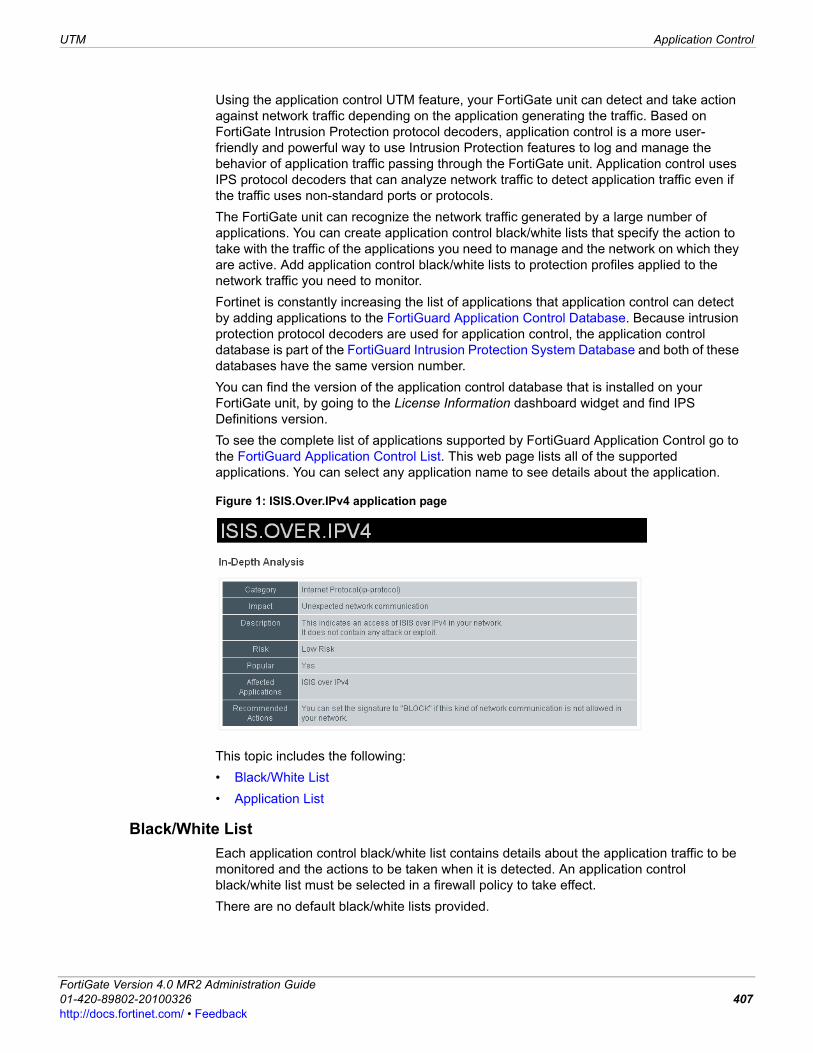
UTM Application Control
F0h
Using the application control UTM feature, your FortiGate unit can detect and take action against network traffic depending on the application generating the traffic. Based on FortiGate Intrusion Protection protocol decoders, application control is a more user-friendly and powerful way to use Intrusion Protection features to log and manage the behavior of application traffic passing through the FortiGate unit. Application control uses IPS protocol decoders that can analyze network traffic to detect application traffic even if the traffic uses non-standard ports or protocols.The FortiGate unit can recognize the network traffic generated by a large number of applications. You can create application control black/white lists that specify the action to take with the traffic of the applications you need to manage and the network on which they are active. Add application control black/white lists to protection profiles applied to the network traffic you need to monitor.Fortinet is constantly increasing the list of applications that application control can detect by adding applications to the FortiGuard Application Control Database. Because intrusion protection protocol decoders are used for application control, the application control database is part of the FortiGuard Intrusion Protection System Database and both of these databases have the same version number. You can find the version of the application control database that is installed on your FortiGate unit, by going to the License Information dashboard widget and find IPS Definitions version.To see the complete list of applications supported by FortiGuard Application Control go to the FortiGuard Application Control List. This web page lists all of the supported applications. You can select any application name to see details about the application.
Figure 1: ISIS.Over.IPv4 application page
This topic includes the following:• Black/White List• Application List
Black/White ListEach application control black/white list contains details about the application traffic to be monitored and the actions to be taken when it is detected. An application control black/white list must be selected in a firewall policy to take effect.There are no default black/white lists provided.
ortiGate Version 4.0 MR2 Administration Guide1-420-89802-20100326 407ttp://docs.fortinet.com/ • Feedback
Application Control UTM
The FortiGate unit examines network traffic for the application entries in the listed order, one at a time, from top to bottom. Whenever a match is detected, the action specified in the matching rule is applied to the traffic and further checks for application entry matches are stopped. Because of this, you can use both actions to create a complex rule with fewer entries.For example, if your organization has standardized on AIM for instant messaging, you can allow AIM and block all other IM clients with just two entries. First, create an entry in which AIM is the specified application. Set the action to Pass. Then create an entry in which the Category is im, the Application is all, and the action is Block. Since the entries are checked from top to bottom, AIM traffic triggers the first rule, and is passed. All other detected IM traffic triggers the second rule, and the FortiGate unit blocks it.In the Black/White List menu, you can enable monitoring so that your network is being monitored. When you select the check box beside Monitor in the Black/White Lists Setting page, you are enabling network monitoring. Black/White lists are configured in UTM > Application Control > Black/White List.
Black/White Lists pageLists each individual black/white list that you created. On this page, you can edit, delete and create a new black/white list.
Create New When you select Create New, you are automatically redirected to the New Application Control Black/White List page. This page provides a name field and a comment field; you must enter a name to go to the Black/White Lists Settings page.
Name The available application control black/white lists.
# of Entries The number of application rules in each application control black/white list.
Profiles The protection profile each application control black/white list has been applied to. If the black/white list has not been applied to a protection profile, this field will be blank.
Comments An optional description of each application control black/white list.
Delete Select to remove the application control black/white list. The delete icon is only available if the application control black/white list is not selected in any protection profiles.
Edit Select to edit the application control black/white list.
Black/White Lists Settings pageProvides settings for configuring the applications for the black/white list. When you are edting a black/white list, you are redirected to this page.
Name If you are editing an existing black/white list and want to change the name, enter a new name in the field. You must select OK to save the change.
Comments If you are editing an existing black/white list and want to change the description, enter the changes in the field. You must select OK to save the change.
OK Select to save changes that you made to the Name and/or Comment fields.
Monitor Select to enable network monitoring.
Create New Select to create a new application entry.
ID A unique number used primarily when re-ordering application entries.
FortiGate Version 4.0 MR2 Administration Guide408 01-420-89802-20100326
http://docs.fortinet.com/ • Feedback
UTM Application Control
F0h
Application ListThe application list displays applications, which also shows their popularity and risk. You can view the details of each application by selecting the application’s name; this link redirects you to the FortiGuard Application Control List where the details are given for the application. You can also filter the information that appears in UTM > Application Control > Application List. For more information about how to filter information in lists, see .To see the complete list of applications supported by FortiGuard Application Control, go to the FortiGuard Application Control List. This web page lists all of the supported applications. You can select any application name to see details about the application. Application lists are configured in UTM > Application Control > Application List.
Category The category indicates the scope of the applications included in the application entry if Application is set to all. For example, if Application is all and Category is toolbar, then all the toolbar applications are included in the application entry even though they are not specified individually.If Application is a single application, the value in Category has no effect on the operation of the application entry.
Application The FortiGate unit will examine network traffic for the listed application. If Application is all, every application in the selected category is included.
Action If the FortiGate unit detects traffic from the specified application, the selected action will be taken.
Logging If traffic from the specified application is detected, the FortiGate unit will log the occurrence and the action taken.
Delete Select to delete the application entry.
Edit Select to edit the application entry.
Insert Select to create a new application entry above the entry in which you selected Insert.
Move Select to move the application entry to a different position in the black/white list.
New Application Entry pageCategory The applications are categorized by type. If you want to choose an IM
application, for example, select the im category, and the application black/white list will show only the im applications.The Category selection can also be used to specify an entire category of applications. To select all IM applications for example, select the im category, and select all as the application. This specifies all the IM applications with a single application control black/white list entry.
Application The FortiGate unit will examine network traffic for the listed application. If Application is all, every application in the selected category is included.
Action If the FortiGate unit detects traffic from the specified application, the selected action will be taken.
Options The options that you can select for the black/white list.
Session TTL The application’s session TTL. If this option is not enabled, the TTL defaults to the setting of the config system session-ttl CLI command.
Enable Logging When enabled, the FortiGate unit will log the occurrence and the action taken if traffic when the specified application is detected.
Enable Packet Logging
ortiGate Version 4.0 MR2 Administration Guide1-420-89802-20100326 409ttp://docs.fortinet.com/ • Feedback
VoIP UTM
VoIPThe FortiGate unit can effectively secure VoIP solutions since it supports VoIP protocols and associates state at the signaling layer with packet flows at the media layer. By using SIP ALG controls, the FortiGate unit can interpret the VoIP signaling protocols used in the network and dynamically open and close ports (pinholes) for each specific VoIP call to maintain security. In UTM > VoIP > Profile, you can configure multiple profiles for applying to firewall policies that concern only VoIP protocols.
ProfileThe Profile menu allows you to configure VoIP profiles for applying to firewall policies. A profile is specific information that defines how the traffic within a policy is examined and what action may be taken based on the examination. VoIP profiles are configured in UTM > VoIP > Profile.
Application List pageLists the applications that are available on the FortiGate unit, which includes their category, popularity rating and risk.
Current Page The current page number of list items that are displayed. Select the left and right arrows to display the first, previous, next or last page of the email address list.
[Total: 1083] The maximum number of applications that are in the FortiGuard Application Control List.
Application Name The name of the application.
Category The category that the application is associated with.
Popularity The level of popularity of the application. The popularity contains three levels: low, medium and high.
Risk The level of risk associated with the application. The risk contains three levels: low, medium and high.
Profile pageLists the profiles that you created for SIP and SCCP protocols. On this page, you can edit, delete or create a new profile for VoIP protocols.
Create New Select to create a new VoIP profile.
Edit Select to change a profile’s settings.
Delete Select to remove a profile.
Name The name of the profile.
Comments A description about the profile. This is an optional setting.
New VoIP Profile pageProvides settings for configuring SIP and SCCP options within the profile. When you edit a VoIP profile, you are automatically redirected to the Edit VoIP Profile page.
Name Enter a name for the profile.
Comments Enter a description about the profile. This is optional.
SIP Configuration settings for SIP protocols.
Limit REGISTER requests
Enter a number for limiting the time it takes to register requests.
Limit INVITE requests Enter a number to limit invitation requests.
Enable Logging Select to log SIP requests.
FortiGate Version 4.0 MR2 Administration Guide410 01-420-89802-20100326
http://docs.fortinet.com/ • Feedback
UTM VoIP
F0h
Enable Logging of Violations
Select to log SIP violations.
SCCP Configuration settings for SCCP protocols.
Limit Call Setup Enter a number to limit call setup time.
Enable Logging Select to log SCCP.
Enable Logging of Violations
Select to local violations of SCCP.
ortiGate Version 4.0 MR2 Administration Guide1-420-89802-20100326 411ttp://docs.fortinet.com/ • Feedback

VoIP UTM
FortiGate Version 4.0 MR2 Administration Guide412 01-420-89802-20100326
http://docs.fortinet.com/ • Feedback
IPsec VPN IPsec VPN overview
F0h
IPsec VPNThis section provides an introduction to Internet Protocol Security (IPsec) VPN configuration options that are available through the web-based manager. FortiGate units support both policy-based (tunnel-mode) and route-based (interface mode) VPNs. For information about how to configure an IPSec VPN, as well as background information, see the FortiGate IPSec VPN User Guide. If you enable virtual domains (VDOMs) on the FortiGate unit, VPN IPSec is configured separately for each virtual domain. For more information, see “Using virtual domains” on page 73.The following topics are included in this section:• IPsec VPN overview• Policy-based versus route-based VPNs• Auto Key (IKE)• Manual Key• Internet browsing• Concentrator• Monitoring VPNs
IPsec VPN overviewThe IPsec VPN menu contains settings and options for configuring an IPsec VPN. An IPsec VPN is a virtual private network that uses the IPsec protocol suite to provide security and protection for the virtual private network; this means that any data coming into the network and any data going out is encrypted. IPsec VPNs that are configured in FortiOS must be configured by using the following general procedure: 1 Define the phase 1 parameters that the FortiGate unit needs to authenticate remote
peers or clients and establish a secure a connection. See “Phase 1 configuration” on page 414.
2 Define the phase 2 parameters that the FortiGate unit needs to create a VPN tunnel with a remote peer or dialup client. See “Phase 2 configuration” on page 417.
Note: L2TP and IPSec is supported for native Windows XP, Windows Vista and Mac OSX native VPN clients.
Note: You must use steps 1 and 2 if you want the FortiGate unit to generate unique IPsec encryption and authentication keys automatically. If a remote VPN peer or client requires a specific IPsec encryption or authentication key, you must configure the FortiGate unit to use manual keys instead. For more information, see “Manual Key” on page 420.
ortiGate Version 4.0 MR2 Administration Guide1-420-89802-20100326 413ttp://docs.fortinet.com/ • Feedback
IPsec VPN overview IPsec VPN
3 Create a firewall policy to permit communication between your private network and the VPN. For a policy-based VPN, the firewall policy action is IPSEC. For an interface-based VPN, the firewall policy action is ACCEPT. See “Configuring firewall policies” on page 258.
Phase 1 is a group of settings that configure the first part of the IPsec VPN. These settings are used to authenticate remote peers or clients, and establishes a secure connection. Phase 2 is a group of settings that configure the second and last of the IPsec VPN, and provide the information the FortiGate unit needs to create a VPN tunnel with a remote peer or dialup client. FortiGate units implement the Encapsulated Security Payload (ESP) protocol. The encrypted packets look like ordinary packets that can be routed through any IP network. Internet Key Exchange (IKE) is performed automatically based on pre-shared keys or X.509 digital certificates. As an option, you can specify manual keys. Interface mode, supported in NAT/Route mode only, creates a virtual interface for the local end of a VPN tunnel.
Policy-based versus route-based VPNsFortiGate units support both policy-based and route-based VPNs. Generally, you can configure route-based VPNs more easily than policy-based VPNs. However, the two types have different requirements that limit where you can use them, as shown in Table 51.
You create a policy-based VPN by defining an IPsec firewall policy between two network interfaces and associating it with the VPN tunnel (phase 1 or manual key) configuration. You need only one firewall policy, even if either end of the VPN can initiate a connection.You create a route-based VPN by enabling IPsec interface mode when you create the VPN phase 1 or manual key configuration. This creates a virtual IPsec interface that is bound to the local interface you selected. You then define an ACCEPT firewall policy to permit traffic to flow between the virtual IPSec interface and another network interface. If either end of the VPN can initiate the connection, you need two firewall policies, one for each direction.Virtual IPsec interface bindings are shown on the network interfaces page. (Go to System > Network > Interface.) The names of all tunnels bound to physical, aggregate, VLAN, inter-VDOM link or wireless interfaces are displayed under their associated interface names in the Name column. For more information, see “Configuring interfaces” on page 89. As with other interfaces, you can include a virtual IPsec interface in a zone.
Hub-and-spoke configurationsTo function as the hub of a hub-and-spoke VPN, the FortiGate unit provides a concentrator function. This is available only for policy-based VPNs, but you can create the equivalent function for a route-based VPN in any of the following ways:
Table 1: Comparison of policy-based and route-based VPNs
Policy-based Route-basedAvailable in NAT/Route or Transparent mode
Available only in NAT/Route mode
Requires a firewall policy with IPSEC action that specifies the VPN tunnel. One policy controls connections in both directions.
Requires only a simple firewall policy with ACCEPT action. A separate policy is required for connections in each direction.
FortiGate Version 4.0 MR2 Administration Guide414 01-420-89802-20100326
http://docs.fortinet.com/ • Feedback
IPsec VPN Auto Key (IKE)
F0h
• Define a firewall policy between each pair of IPsec interfaces that you want to concentrate. This can be time-consuming to maintain if you have many site-to-site connections, since the number of policies required increases rapidly as the number of spokes increases.
• Put all the IPsec interfaces into a zone and then define a single zone-to-zone policy.• Put all the IPsec interfaces in a zone and enable intra-zone traffic. There must be more
than one IPsec interface in the zone.
Redundant configurationsRoute-based VPNs help to simplify the implementation of VPN tunnel redundancy. You can configure several routes for the same IP traffic with different route metrics. You can also configure the exchange of dynamic (RIP, OSPF, or BGP) routing information through VPN tunnels. If the primary VPN connection fails or the priority of a route changes through dynamic routing, an alternative route will be selected to forward traffic through the redundant connection. A simple way to provide failover redundancy is to create a backup IPsec interface. You can do this in the CLI. For more information, including an example configuration, see the monitor-phase1 keyword for the ipsec vpn phase1-interface command in the FortiGate CLI Reference.
RoutingOptionally, through the CLI, you can define a specific default route for a virtual IPsec interface. For more information, see the default-gw variable for the vpn ipsec phase1-interface command in the FortiGate CLI Reference.
Auto Key (IKE)You can configure two VPN peers (or a FortiGate dialup server and a VPN client) to generate unique Internet Key Exchange (IKE) keys automatically during the IPsec phase 1 and phase 2 exchanges.When you define phase 2 parameters, you can choose any set of phase 1 parameters to set up a secure connection for the tunnel and authenticate the remote peer.Auto Key configuration applies to both tunnel-mode and interface-mode VPNs.Two VPN peers are configured in VPN > IPsec > Auto Key (IKE).
Auto Key (IKE) pageLists each phase 1 and phase 2 configurations of the two VPN peers that make up the IKE key.
Create Phase 1 Create a new phase 1 tunnel configuration. For more information, see “Phase 1 configuration” on page 414.
Create Phase 2 Create a new phase 2 configuration. For more information, see “Phase 2 configuration” on page 417.
Phase 1 The names of existing phase 1 tunnel configurations.
Phase 2 The names of existing phase 2 configurations.
Interface Binding The names of the local interfaces to which IPsec tunnels are bound. These can be physical, aggregate, VLAN, inter-VDOM link or wireless interfaces.
Edit Select to modify a setting for the exchanges.
Delete Select to remove the IKE key.
ortiGate Version 4.0 MR2 Administration Guide1-420-89802-20100326 415ttp://docs.fortinet.com/ • Feedback
Auto Key (IKE) IPsec VPN
Phase 1 configurationIn phase 1, two VPN peers (or a FortiGate dialup server and a VPN client) authenticate each other and exchange keys to establish a secure communication channel between them. The basic phase 1 settings associate IPsec phase 1 parameters with a remote gateway and determine:• whether the various phase 1 parameters will be exchanged in multiple rounds with
encrypted authentication information (main mode) or in a single message with authentication information that is not encrypted (Aggressive mode)
• whether a pre-shared key or digital certificates will be used to authenticate the identities of the two VPN peers (or a VPN server and its client)
• whether a special identifier, certificate distinguished name, or group name will be used to identify the remote VPN peer or client when a connection attempt is made.
New Phase 1 pageProvides settings for configuring a phase 1. When you select Create New Phase 1 on the Auto Key (IKE) page, you are automatically redirected to the New Phase 1 page.
Name Type a name to represent the phase 1 definition. The maximum name length is 15 characters for an interface mode VPN, 35 characters for a policy-based VPN. If Remote Gateway is Dialup User, the maximum name length is further reduced depending on the number of dialup tunnels that can be established: by 2 for up to 9 tunnels, by 3 for up to 99 tunnels, 4 for up to 999 tunnels, and so on.For a tunnel mode VPN, the name should reflect where the remote connection originates. For a route-based tunnel, the FortiGate unit also uses the name for the virtual IPsec interface that it creates automatically.
Remote Gateway Select the category of the remote connection:Static IP Address — If the remote peer has a static IP address. Dialup User — If one or more FortiClient or FortiGate dialup clients with dynamic IP addresses will connect to the FortiGate unit.Dynamic DNS — If a remote peer that has a domain name and subscribes to a dynamic DNS service will connect to the FortiGate unit.
IP Address If you selected Static IP Address, type the IP address of the remote peer.
Dynamic DNS If you selected Dynamic DNS, type the domain name of the remote peer.
Local Interface This option is available in NAT/Route mode only. Select the name of the interface through which remote peers or dialup clients connect to the FortiGate unit. By default, the local VPN gateway IP address is the IP address of the interface that you selected. Optionally, you can specify a unique IP address for the VPN gateway in the Advanced settings.
Mode Select Main (ID Protection) or Aggressive:• In Main mode, the phase 1 parameters are exchanged in multiple
rounds with encrypted authentication information.• In Aggressive mode, the phase 1 parameters are exchanged in
single message with authentication information that is not encrypted.
When the remote VPN peer has a dynamic IP address and is authenticated by a pre-shared key, you must select Aggressive mode if there is more than one dialup phase1 configuration for the interface IP address.When the remote VPN peer has a dynamic IP address and is authenticated by a certificate, you must select Aggressive mode if there is more than one phase 1 configuration for the interface IP address and these phase 1 configurations use different proposals.Peer Options settings may require a particular mode. See Peer Options, below.
FortiGate Version 4.0 MR2 Administration Guide416 01-420-89802-20100326
http://docs.fortinet.com/ • Feedback
IPsec VPN Auto Key (IKE)
F0h
Phase 1 advanced configuration settingsYou use the advanced P1 Proposal parameters to select the encryption and authentication algorithms that the FortiGate unit uses to generate keys for the IKE exchange. You can also select these advanced settings to ensure the smooth operation of phase 1 negotiations.
Authentication Method Select Preshared Key or RSA Signature.
Pre-shared Key If you selected Pre-shared Key, type the pre-shared key that the FortiGate unit will use to authenticate itself to the remote peer or dialup client during phase 1 negotiations. You must define the same value at the remote peer or client. The key must contain at least 6 printable characters and should be known only by network administrators. For optimum protection against currently known attacks, the key should consist of a minimum of 16 randomly chosen alphanumeric characters.
Certificate Name If you selected RSA Signature, select the name of the server certificate that the FortiGate unit will use to authenticate itself to the remote peer or dialup client during phase 1 negotiations. For information about obtaining and loading the required server certificate, see the FortiGate Certificate Management User Guide.
Peer Options One or more of the following options are available to authenticate VPN peers or clients, depending on the Remote Gateway and Authentication Method settings.
Accept any peer ID Accept the local ID of any remote VPN peer or client. The FortiGate unit does not check identifiers (local IDs). You can set Mode to Aggressive or Main.You can use this option with RSA Signature authentication. But, for highest security, you should configure a PKI user/group for the peer and set Peer Options to Accept this peer certificate only.
Accept this peer ID This option is available only if the remote peer has a dynamic IP address. Enter the identifier that is used to authenticate the remote peer. This identifier must match the identifier that the remote peer’s administrator has configured. If the remote peer is a FortiGate unit, the identifier is specified in the Local ID field of the phase 1 configuration. If the remote peer is a FortiClient dialup client, the identifier is specified in the Local ID field, accessed by selecting Config in the Policy section of the VPN connection’s Advanced Settings.
Accept peer ID in dialup group
Authenticate multiple FortiGate or FortiClient dialup clients that use unique identifiers and unique pre-shared keys (or unique pre-shared keys only) through the same VPN tunnel. You must create a dialup user group for authentication purposes. (For more information, see “User Group” on page 460.) Select the group from the list next to the Accept peer ID in dialup group option. For more information about configuring FortiGate dialup clients, see the FortiGate IPSec VPN User Guide. For more information about configuring FortiClient dialup clients, see the Authenticating FortiClient Dialup Clients Technical Note. You must set Mode to Aggressive when the dialup clients use unique identifiers and unique pre-shared keys. If the dialup clients use unique pre-shared keys only, you can set Mode to Main if there is only one dialup phase 1 configuration for this interface IP address.
Advanced Defines advanced phase 1 parameters. For more information, see “Phase 1 advanced configuration settings” on page 415.
Advanced section of the New Phase 1 pageEnable IPsec Interface Mode
This is available in NAT/Route mode only.Create a virtual interface for the local end of the VPN tunnel. Select this option to create a route-based VPN, clear it to create a policy-based VPN.
ortiGate Version 4.0 MR2 Administration Guide1-420-89802-20100326 417ttp://docs.fortinet.com/ • Feedback
Auto Key (IKE) IPsec VPN
IKE Version Select the version of IKE to use: 1 or 2. The default is 1. This is available only if IPsec Interface Mode is enabled. For more information about IKE v2, refer to RFC 4306.IKE v2 is not available if Mode is Aggressive.When IKE Version is 2, Mode and XAUTH are not available.
IPv6 Version Select if you want to use IPv6 addresses for the remote gateway and interface IP addresses. This is available only when Enable IPsec Interface Mode is enabled and IPv6 Support is enabled in the administrative settings.
Local Gateway IP If you selected Enable IPsec Interface Mode, specify an IP address for the local end of the VPN tunnel. Select one of the following:Main Interface IP — The FortiGate unit obtains the IP address of the interface from the network interface settings. For more information, see “Configuring interfaces” on page 89.Specify — You can specify a secondary address of the interface selected in the phase 1 Local Interface field. For more information, see “Local Interface” on page 414. You cannot configure Interface mode in a Transparent mode VDOM.
P1 Proposal Select the encryption and authentication algorithms used to generate keys for protecting negotiations.Add or delete encryption and authentication algorithms as required. Select a minimum of one and a maximum of three combinations. The remote peer or client must be configured to use at least one of the proposals that you define.
Select one of the following symmetric-key algorithms:DES — Digital Encryption Standard, a 64-bit block algorithm that uses a 56-bit key.3DES — Triple-DES, in which plain text is encrypted three times by three keys.AES128 — a 128-bit block Cipher Block Chaining (CBC) algorithm that uses a 128-bit key.AES192 — a 128-bit block Cipher Block Chaining (CBC) algorithm that uses a 192-bit key.AES256 — a 128-bit block Cipher Block Chaining (CBC) algorithm that uses a 256-bit key.
Select either of the following message digests to check the authenticity of messages during phase 1 negotiations:MD5 — Message Digest 5, the hash algorithm developed by RSA Data Security.SHA1 — Secure Hash Algorithm 1, which produces a 160-bit message digest.SHA256 — Secure Hash Algorithm 2, which produces a 256-bit message digest.To specify a third combination, use the Add button beside the fields for the second combination.
DH Group Select one or more Diffie-Hellman groups from DH group 1, 2, 5 and 14. At least one of the DH Group settings on the remote peer or client must match one the selections on the FortiGate unit.
Keylife Type the time (in seconds) that must pass before the IKE encryption key expires. When the key expires, a new key is generated without interrupting service. The keylife can be from 120 to 172 800 seconds.
Local ID If the FortiGate unit will act as a VPN client and you are using peer IDs for authentication purposes, enter the identifier that the FortiGate unit will supply to the VPN server during the phase 1 exchange.If the FortiGate unit will act as a VPN client and you are using security certificates for authentication, select the distinguished name (DN) of the local server certificate that the FortiGate unit will use for authentication purposes. If the FortiGate unit is a dialup client and will not be sharing a tunnel with other dialup clients (that is, the tunnel will be dedicated to this FortiGate dialup client), set Mode to Aggressive.
FortiGate Version 4.0 MR2 Administration Guide418 01-420-89802-20100326
http://docs.fortinet.com/ • Feedback
IPsec VPN Auto Key (IKE)
F0h
Phase 2 configurationAfter IPsec phase 1 negotiations end successfully, you begin phase 2. You configure the phase 2 parameters to define the algorithms that the FortiGate unit may use to encrypt and transfer data for the remainder of the session. During phase 2, you select specific IPsec security associations needed to implement security services and establish a tunnel. The basic phase 2 settings associate IPsec phase 2 parameters with the phase 1 configuration that specifies the remote end point of the VPN tunnel. In most cases, you need to configure only basic phase 2 settings.
XAuth This option supports the authentication of dialup clients. It is available for IKE v1 only.
Disable — Select if you do not use XAuth.
Enable as Client — If the FortiGate unit is a dialup client, type the user name and password that the FortiGate unit will need to authenticate itself to the remote XAuth server.
Enable as Server — This is available only if Remote Gateway is set to Dialup User. Dialup clients authenticate as members of a dialup user group. You must first create a user group for the dialup clients that need access to the network behind the FortiGate unit. For more information, see “Configuring a user group” on page 463.
You must also configure the FortiGate unit to forward authentication requests to an external RADIUS or LDAP authentication server. For information about these topics, see “Configuring a RADIUS server” on page 452 or “Configuring an LDAP server” on page 454.
Select a Server Type setting to determine the type of encryption method to use between the FortiGate unit, the XAuth client and the external authentication server, and then select the user group from the User Group list.
Username Enter the user name that is used for authentication.
Password Enter the password that is used for authentication.
NAT Traversal Select the check box if a NAT device exists between the local FortiGate unit and the VPN peer or client. The local FortiGate unit and the VPN peer or client must have the same NAT traversal setting (both selected or both cleared) to connect reliably.
Keepalive Frequency If you enabled NAT-traversal, enter a keepalive frequency setting. The value represents an interval ranging from 10 to 900 seconds.
Dead Peer Detection Select this check box to reestablish VPN tunnels on idle connections and clean up dead IKE peers if required. You can use this option to receive notification whenever a tunnel goes up or down, or to keep the tunnel connection open when no traffic is being generated inside the tunnel. (For example, in scenarios where a dialup client or dynamic DNS peer connects from an IP address that changes periodically, traffic may be suspended while the IP address changes).With Dead Peer Detection selected, you can use the config vpn ipsec phase1 (tunnel mode) or config vpn ipsec phase1-interface (interface mode) CLI command to optionally specify a retry count and a retry interval. For more information, see the FortiGate CLI Reference.
New Phase 2 pageProvides settings for configuring Phase 2. When you select Create Phase 2 on the Auto Key (IKE) page, you are automatically redirected to the New Phase 2 page.
Name Type a name to identify the phase 2 configuration.
ortiGate Version 4.0 MR2 Administration Guide1-420-89802-20100326 419ttp://docs.fortinet.com/ • Feedback
Auto Key (IKE) IPsec VPN
Phase 2 advanced configuration settingsIn phase 2, the FortiGate unit and the VPN peer or client exchange keys again to establish a secure communication channel between them. You select the encryption and authentication algorithms needed to generate keys for protecting the implementation details of Security Associations (SAs). These are called P2 Proposal parameters. The keys are generated automatically using a Diffie-Hellman algorithm. You can use a number of additional advanced phase 2 settings to enhance the operation of the tunnel.
Phase 1 Select the phase 1 tunnel configuration. For more information, see “Phase 1 configuration” on page 414. The phase 1 configuration describes how remote VPN peers or clients will be authenticated on this tunnel, and how the connection to the remote peer or client will be secured.
Advanced Define advanced phase 2 parameters. For more information, see “Phase 2 advanced configuration settings” on page 418.
Advanced section of New Phase 2 pageP2 Proposal Select the encryption and authentication algorithms that will be proposed to
the remote VPN peer. You can specify up to three proposals. To establish a VPN connection, at least one of the proposals that you specify must match configuration on the remote peer.Initially there are two proposals. Add and Delete icons are next to the second Authentication field. To specify only one proposal, select Delete to remove the second proposal. To specify a third proposal, select Add. It is invalid to set both Encryption and Authentication to NULL.
Encryption Select one of the following symmetric-key algorithms:NULL — Do not use an encryption algorithm.DES — Digital Encryption Standard, a 64-bit block algorithm that uses a 56-bit key.3DES — Triple-DES, in which plain text is encrypted three times by three keys.AES128 — a 128-bit block Cipher Block Chaining (CBC) algorithm that uses a 128-bit key.AES192 — a 128-bit block Cipher Block Chaining (CBC) algorithm that uses a 192-bit key.AES256 — a 128-bit block Cipher Block Chaining (CBC) algorithm that uses a 256-bit key.
Authentication Select one of the following message digests to check the authenticity of messages during an encrypted session:NULL — Do not use a message digest.MD5 — Message Digest 5, the hash algorithm developed by RSA Data Security.SHA1 — Secure Hash Algorithm 1, which produces a 160-bit message digest.SHA256 — Secure Hash Algorithm 2, which produces a 256-bit message digest.
Enable replay detection
Optionally enable or disable replay detection. Replay attacks occur when an unauthorized party intercepts a series of IPsec packets and replays them back into the tunnel.
Enable perfect forward secrecy (PFS)
Enable or disable PFS. Perfect forward secrecy (PFS) improves security by forcing a new Diffie-Hellman exchange whenever keylife expires.
DH Group Select one Diffie-Hellman group (1, 2, 5 or 14). This must match the DH Group that the remote peer or dialup client uses.
Keylife Select the method for determining when the phase 2 key expires: Seconds, KBytes, or Both. If you select Both, the key expires when either the time has passed or the number of KB have been processed. The range is from 120 to 172 800 seconds, or from 5120 to 2 147 483 648 KB.
FortiGate Version 4.0 MR2 Administration Guide420 01-420-89802-20100326
http://docs.fortinet.com/ • Feedback
IPsec VPN Auto Key (IKE)
F0h
Autokey Keep Alive Select the check box if you want the tunnel to remain active when no data is being processed.
DHCP-IPSec Provide IP addresses dynamically to VPN clients. This is available for phase 2 configurations associated with a dialup phase 1 configuration. You also need configure a DHCP server or relay on the private network interface. You must configure the DHCP parameters separately. For more information, see “System DHCP Server” on page 131.If you configure the DHCP server to assign IP addresses based on RADIUS user group attributes, you must also set the Phase 1 Peer Options to Accept peer ID in dialup group and select the appropriate user group. See “Phase 1 configuration” on page 414.If the FortiGate unit acts as a dialup server and you manually assigned FortiClient dialup clients VIP addresses that match the network behind the dialup server, selecting the check box will cause the FortiGate unit to act as a proxy for the dialup clients.
Quick Mode Selector Optionally specify the source and destination IP addresses to be used as selectors for IKE negotiations. If the FortiGate unit is a dialup server, you should keep the default value 0.0.0.0/0 unless you need to circumvent problems caused by ambiguous IP addresses between one or more of the private networks making up the VPN. You can specify a single host IP address, an IP address range, or a network address. You may optionally specify source and destination port numbers and a protocol number.If you are editing an existing phase 2 configuration, the Source address and Destination address fields are unavailable if the tunnel has been configured to use firewall addresses as selectors. This option exists only in the CLI. For more information, see the dst-addr-type, dst-name, src-addr-type and src-name keywords for the vpn ipsec phase2 command in the FortiGate CLI Reference.
Source address If the FortiGate unit is a dialup server, type the source IP address that corresponds to the local senders or network behind the local VPN peer (for example, 172.16.5.0/24 or 172.16.5.0/255.255.255.0 for a subnet, or 172.16.5.1/32 or 172.16.5.1/255.255.255.255 for a server or host, or 192.168.10.[80-100] or 192.168.10.80-192.168.10.100 for an address range). A value of 0.0.0.0/0 means all IP addresses behind the local VPN peer.If the FortiGate unit is a dialup client, source address must refer to the private network behind the FortiGate dialup client.
Source port Type the port number that the local VPN peer uses to transport traffic related to the specified service (protocol number). The range is from 0 to 65535. To specify all ports, type 0.
Destination address
Type the destination IP address that corresponds to the recipients or network behind the remote VPN peer (for example, 192.168.20.0/24 for a subnet, or 172.16.5.1/32 for a server or host, or 192.168.10.[80-100] for an address range). A value of 0.0.0.0/0 means all IP addresses behind the remote VPN peer.
Destination port Type the port number that the remote VPN peer uses to transport traffic related to the specified service (protocol number). The range is from 0 to 65535. To specify all ports, type 0.
Protocol Type the IP protocol number of the service. The range is from 0 to 255. To specify all services, type 0.
Note: You can configure settings so that VPN users can browse the Internet through the FortiGate unit. For more information, see “Internet browsing” on page 422.
ortiGate Version 4.0 MR2 Administration Guide1-420-89802-20100326 421ttp://docs.fortinet.com/ • Feedback
Manual Key IPsec VPN
Manual Key
If required, you can manually define cryptographic keys for establishing an IPsec VPN tunnel. You would define manual keys in situations where:• You require prior knowledge of the encryption or authentication key (that is, one of the
VPN peers requires a specific IPsec encryption or authentication key).• You need to disable encryption and authentication.In both cases, you do not specify IPsec phase 1 and phase 2 parameters; you define manual keys by going to VPN > IPsec > Manual Key instead.
New manual key configuration
If one of the VPN devices is manually keyed, the other VPN device must also be manually keyed with the identical authentication and encryption keys. In addition, it is essential that both VPN devices be configured with complementary Security Parameter Index (SPI) settings. The administrators of the devices need to cooperate to achieve this.Each SPI identifies a Security Association (SA). The value is placed in ESP datagrams to link the datagrams to the SA. When an ESP datagram is received, the recipient refers to the SPI to determine which SA applies to the datagram. You must manually specify an SPI for each SA. There is an SA for each direction, so for each VPN you must specify two SPIs, a local SPI and a remote SPI, to cover bidirectional communications between two VPN devices.
Caution: You should use manual keys only if it is unavoidable. There are potential difficulties in keeping keys confidential and in propagating changed keys to remote VPN peers securely.
Manual Key pageLists each individual cryptographic key that you created for establishing an IPSec VPN.
Create New Create a new manual key configuration. See “New manual key configuration” on page 420.
Tunnel Name The names of existing manual key configurations.
Remote Gateway The IP addresses of remote peers or dialup clients.
Encryption Algorithm The names of the encryption algorithms specified in the manual key configurations.
Authentication Algorithm
The names of the authentication algorithms specified in the manual key configurations.
Edit Select to modify settings of a cryptographic key.
Delete Select to remove a cryptographic key from the list.
Caution: If you are not familiar with the security policies, SAs, selectors, and SA databases for your particular installation, do not attempt the following procedure without qualified assistance.
New Manual Key pageProvides settings for configuring a cryptographic key for the IPSec VPN.
Name Type a name for the VPN tunnel. The maximum name length is 15 characters for an interface mode VPN, 35 characters for a policy-based VPN.
Local SPI Type a hexadecimal number (up to 8 characters, 0-9, a-f) that represents the SA that handles outbound traffic on the local FortiGate unit. The valid range is from 0x100 to 0xffffffff. This value must match the Remote SPI value in the manual key configuration at the remote peer.
FortiGate Version 4.0 MR2 Administration Guide422 01-420-89802-20100326
http://docs.fortinet.com/ • Feedback
IPsec VPN Manual Key
F0h
Remote SPI Type a hexadecimal number (up to 8 characters, 0-9, a-f) that represents the SA that handles inbound traffic on the local FortiGate unit. The valid range is from 0x100 to 0xffffffff. This value must match the Local SPI value in the manual key configuration at the remote peer.
Remote Gateway Type the IP address of the public interface to the remote peer. The address identifies the recipient of ESP datagrams.
Local Interface This option is available in NAT/Route mode only. Select the name of the interface to which the IPsec tunnel will be bound. The FortiGate unit obtains the IP address of the interface from the network interface settings. For more information, see “Configuring interfaces” on page 89.
Encryption Algorithm
Select one of the following symmetric-key encryption algorithms:NULL — Do not use an encryption algorithm.DES — Digital Encryption Standard, a 64-bit block algorithm that uses a 56-bit key.3DES — Triple-DES, in which plain text is encrypted three times by three keys.AES128 — a 128-bit block Cipher Block Chaining (CBC) algorithm that uses a 128-bit key.AES192 — a 128-bit block Cipher Block Chaining (CBC) algorithm that uses a 192-bit key.AES256 — a 128-bit block Cipher Block Chaining (CBC) algorithm that uses a 256-bit key.Note: The algorithms for encryption and authentication cannot both be NULL.
Encryption Key Enter an encryption key appropriate to the encryption algorithm:• for NULL, • for DES, type a 16-character hexadecimal number (0-9, a-f).• for 3DES, type a 48-character hexadecimal number (0-9, a-f) separated
into three segments of 16 characters.• for AES128, type a 32-character hexadecimal number (0-9, a-f) separated
into two segments of 16 characters.• for AES192, type a 48-character hexadecimal number (0-9, a-f) separated
into three segments of 16 characters.• for AES256, type a 64-character hexadecimal number (0-9, a-f) separated
into four segments of 16 characters.
Authentication Algorithm
Select one of the following message digests:NULL –– Do not use a message digest.MD5 — Message Digest 5 algorithm, which produces a 128-bit message digest.SHA1 — Secure Hash Algorithm 1, which produces a 160-bit message digest.SHA256 — Secure Hash Algorithm 2, which produces a 256-bit message digest.Note: The Algorithms for encryption and authentication cannot both be NULL.
Authentication Key Enter an authentication key appropriate to the authentication algorithm:• for MD5, type a 32-character hexadecimal number separated into two
segments of 16 characters.• for SHA1, type a 40-character hexadecimal number separated into two
segments of 16 characters and a third segment of 8 characters.• for SHA256, type a 64-character hexadecimal number separated into four
segments of 16 characters.Digits can be 0 to 9, and a to f.
IPsec Interface Mode
Create a virtual interface for the local end of the VPN tunnel. Select this check box to create a route-based VPN, clear it to create a policy-based VPN.This is available only in NAT/Route mode.
ortiGate Version 4.0 MR2 Administration Guide1-420-89802-20100326 423ttp://docs.fortinet.com/ • Feedback
Internet browsing IPsec VPN
Internet browsingBy using appropriate firewall policies, you can enable VPN users to browse the Internet through the FortiGate unit. The required policies are different for policy-based and route-based VPNs. For more information, see “Configuring firewall policies” on page 258.
Concentrator In a hub-and-spoke configuration, policy-based VPN connections to a number of remote peers radiate from a single, central FortiGate unit. Site-to-site connections between the remote peers do not exist; however, You can establish VPN tunnels between any two of the remote peers through the FortiGate unit “hub”.In a hub-and-spoke network, all VPN tunnels terminate at the hub. The peers that connect to the hub are known as “spokes”. The hub functions as a concentrator on the network, managing all VPN connections between the spokes. VPN traffic passes from one tunnel to the other through the hub.You define a concentrator to include spokes in the hub-and-spoke configuration. You create the concentrator in VPN > IPSec > Concentrator. A concentrator configuration specifies which spokes to include in an IPsec hub-and-spoke configuration.
Monitoring VPNsYou can use the IPsec monitor to view activity on IPsec VPN tunnels and start or stop those tunnels. The display provides a list of addresses, proxy IDs, and timeout information for all active tunnels, including tunnel mode and route-based (interface mode) tunnels.For Dialup VPNs, the list provides status information about the VPN tunnels established by dialup clients, including their IP addresses. The number of tunnels shown in the list can change as dialup clients connect and disconnect.For Static IP or dynamic DNS VPNs, the list provides status and IP addressing information about VPN tunnels, active or not, to remote peers that have static IP addresses or domain names. You can also start and stop individual tunnels from the list.
Concentrator pageLists each individual concentrator which is made up of spokes. On this page, you can edit, delete or create a new concentrator.
Create New Define a new concentrator for an IPsec hub-and-spoke configuration. For more information, see “Monitoring VPNs” on page 422.
Concentrator Name The names of existing IPsec VPN concentrators.
Members The tunnels that are associated with the concentrators.
Delete Select to remove a concentrator from the list.
Edit Select to modify the settings within a concentrator.
New VPN Concentrator
Provides settings for configuring a concentrator which is made up of IPSec tunnels which are called members.
Concentrator Name Type a name for the concentrator.
Available Tunnels A list of defined IPsec VPN tunnels. Select a tunnel from the list and then select the right arrow. Repeat these steps until all of the tunnels associated with the spokes are included in the concentrator.
Members A list of tunnels that are members of the concentrator. To remove a tunnel from the concentrator, select the tunnel and select the left arrow.
FortiGate Version 4.0 MR2 Administration Guide424 01-420-89802-20100326
http://docs.fortinet.com/ • Feedback
IPsec VPN Monitoring VPNs
F0h
You can use filters to control the information displayed in the list. For more information, see “Adding filters to web-based manager lists” on page 33.
Monitor pageLists all IPSec VPNs that are currently being monitored. You can view either just Dialup or Static or Dynamic DNS IPSec VPNs.
Type Select the types of VPN to display: “All”, “Dialup”, or “Static IP or Dynamic DNS”.
Column Settings
Customize the table view. You can select the columns to hide or display and specify the column displaying order in the table. For more information, see “Using column settings to control the columns displayed” on page 35 and “” on page 36.
Clear All Filters Select to clear any column display filters you might have applied.
Page Controls The current page number of list items that are displayed. Select the left and right arrows to display the first, previous, next or last page of monitored VPNs.
Filter icons Edit the column filters to filter or sort the IPsec monitor list according to the criteria you specify. For more information, see “Adding filters to web-based manager lists” on page 33.
Name The name of the phase 1 configuration for the VPN.
Type Appears only when viewing all types of IPSec VPNs
Remote Gateway
The public IP address of the remote host device, or if a NAT device exists in front of the remote host, the public IP address of the NAT device.
Remote Port The UDP port of the remote host device, or if a NAT device exists in front of the remote host, the UDP port of the NAT device. Zero (0) indicates that any port can be used.
TimeoutProxy ID Source The IP addresses of the hosts, servers, or private networks behind the FortiGate
unit. The page may display a network range if the source address in the firewall encryption policy was expressed as a range of IP addresses.
Proxy ID Destination
When a FortiClient dialup client establishes a tunnel:• If VIP addresses are not used, the Proxy ID Destination field displays the
public IP address of the remote host Network Interface Card (NIC).• If VIP addresses were configured (manually or through FortiGate DHCP
relay), the Proxy ID Destination field displays either the VIP address belonging to the FortiClient dialup client, or the subnet address from which VIP addresses were assigned.
When a FortiGate dialup client establishes a tunnel, the Proxy ID Destination field displays the IP address of the remote private network.
Status A green arrow means the tunnel is currently processing traffic. Select to bring down the tunnel.A red arrow means the tunnel is not processing traffic. Select to bring up the tunnel.
Reset Statistics Select to reset the current statistics that are on the page.
ortiGate Version 4.0 MR2 Administration Guide1-420-89802-20100326 425ttp://docs.fortinet.com/ • Feedback
Monitoring VPNs IPsec VPN
FortiGate Version 4.0 MR2 Administration Guide426 01-420-89802-20100326
http://docs.fortinet.com/ • Feedback
PPTP VPN PPTP configuration using FortiGate web-based manager
F0h
PPTP VPNFortiGate units support PPTP to tunnel PPP traffic between two VPN peers. Windows or Linux PPTP clients can establish a PPTP tunnel with a FortiGate unit that has been configured to act as a PPTP server. As an alternative, you can configure the FortiGate unit to forward PPTP packets to a PPTP server on the network behind the FortiGate unit.PPTP VPN is available only in NAT/Route mode. The current maximum number of PPTP sessions is 254. If you enable virtual domains (VDOMs) on the FortiGate unit, you need to configure VPN PPTP separately for each virtual domain. For more information, see “Using virtual domains” on page 73.
When you intend to use the FortiGate unit as a PPTP gateway, you can select a PPTP client IP from a local address range or use the server defined in the PPTP user group. You select which method to use for IP address retrieval and, in the case of the user group server, provide the IP address and the user group.
This section explains how to specify a range of IP addresses for PPTP clients or configure the PPTP client-side IP address to be used in the tunnel setup. For information about how to perform other related PPTP VPN setup tasks, see the FortiGate PPTP VPN User Guide.The following topics are included in this section:• PPTP configuration using FortiGate web-based manager• PPTP configuration using CLI commands
PPTP configuration using FortiGate web-based managerTo configure the PPTP tunnel, create a customized screen in the web-based manager. The PPTP Range tab is found under the Categories heading as a selection in the Additional category:For information about creating customized screens in the FortiGate web-based manager, see “Customizable web-based manager” on page 250.PPTP requires two IP addresses, one for each end of the tunnel. The PPTP address range is the range of addresses reserved for remote PPTP clients. When the remote PPTP client establishes a connection, the FortiGate unit assigns an IP address from the reserved range of IP addresses to the client PPTP interface or retrieves the assigned IP address from the PPTP user group. If you use the PPTP user group, you must also define the FortiGate end of the tunnel by entering the IP address of the unit in Local IP (web-based manager) or local-ip (CLI). The PPTP client uses the assigned IP address as its source address for the duration of the connection.To enable PPTP and specify the PPTP address range or specify the IP address for the peer’s remote IP on the PPTP client side, go to the customized screen in the web-based manager, select the required options, and then select Apply.
Note: The PPTP feature is disabled by default in the FortiGate web-based manager. You configure the PPTP tunnel configuration by creating a customized FortiGate screen.
ortiGate Version 4.0 MR2 Administration Guide1-420-89802-20100326 427ttp://docs.fortinet.com/ • Feedback
PPTP configuration using CLI commands PPTP VPN
PPTP configuration using CLI commandsIf you prefer not to set up a customized screen in the FortiGate web-based manager, you can configure the PPTP tunnel using CLI.
Syntaxconfig vpn pptp
set eip <address_ipv4>set ip-mode {range | usrgrp}set local-ip <address_localip>set sip <address_ipv4>set status {disable | enable}set usrgrp <group_name>
end
Note: The start and end IPs in the PPTP address range must be in the same 24-bit subnet, e.g. 192.168.1.1 - 192.168.1.254.
Enable PPTP Enable PPTP. You must add a user group before you can select the option. See “User Group” on page 460.
IP Mode Select how PPTP users are assigned an IP address.
Range User’s IP addresses are assigned from the range of IP addresses configured by Starting IP and Ending IP.
User Group User’s IP addresses are assigned by the user group used to authenticate the user. Select the user group. See “Dynamically assigning VPN client IP addresses from a user group” on page 464.
Starting IP Type the starting address in the range of reserved IP addresses.
Ending IP Type the ending address in the range of reserved IP addresses.
Local IP Type the IP address to be used for the peer’s remote IP on the PPTP client side.
User Group Select the PPTP user group from the list.
Disable PPTP Select to disable PPTP support.
Variables Description Defaulteip <address_ipv4> The ending address of the PPTP address range. 0.0.0.0
ip-mode {range | usrgrp}
Select one of:range — Assign user IP addresses from the IP address range of configured by sip and eip.usrgrp — Retrieve the IP address from the user group used to authenticate the user. Select the user group in usrgrp.
range
local-ip <address_localip>
Enter the IP address to be used for the peer’s remote IP on the PPTP client side.
0.0.0.0
sip <address_ipv4> The starting address of the PPTP IP address range.
0.0.0.0
status {disable | enable}
Enable or disable PPTP VPN. disable
FortiGate Version 4.0 MR2 Administration Guide428 01-420-89802-20100326
http://docs.fortinet.com/ • Feedback
PPTP VPN PPTP configuration using CLI commands
F0h
usrgrp <group_name> This keyword is available when ip-mode is set to usrgrp.Enter the name of the user group for authenticating PPTP clients. The user group must be added to the FortiGate configuration before it can be specified here.
Null.
eip <address_ipv4> The ending address of the PPTP address range. 0.0.0.0
ortiGate Version 4.0 MR2 Administration Guide1-420-89802-20100326 429ttp://docs.fortinet.com/ • Feedback
PPTP configuration using CLI commands PPTP VPN
FortiGate Version 4.0 MR2 Administration Guide430 01-420-89802-20100326
http://docs.fortinet.com/ • Feedback
SSL VPN SSL VPN overview
F0h
SSL VPNThis section is an introduction to the SSL VPN menu. For more information about configuring SSL VPN, including additional general information about SSL VPN, see the FortiGate SSL VPN chapter of the FortiOS Handbook. If you enable virtual domains (VDOMs) on the FortiGate unit, VPN SSL is configured separately for each virtual domain. For more information, see “Using virtual domains” on page 73.The following topics are included in this section:• SSL VPN overviewConfig• Portal• Virtual Desktop Application Control• Host Check• SSL VPN monitor list
SSL VPN overviewAn SSL VPN (Secure Sockets Layer virtual private network) is a form of VPN that can be used with a standard Web browser. SSL VPN does not require the installation of specialized client software on end users’ computers, and is ideal for applications including web-based email, business and government directories, file sharing, remote backup, remote system management, and consumer-level electronic commerce.The two modes of SSL VPN operation (supported in NAT/Route mode only) are:• web-only mode, for thin remote clients equipped with a web-browser only.• tunnel mode, for remote computers that run a variety of client and server applications.When the FortiGate unit provides services in web-only mode, a secure connection between the remote client and the FortiGate unit is established through the SSL VPN security in the FortiGate unit and the SSL security in the web browser. After the connection has been established, the FortiGate unit provides access to selected services and network resources through a web portal. The FortiGate SSL VPN web portal has a widget-based layout with customizable themes. Each widget is displayed in a 1- or 2-column format with the ability to modify settings, minimize the widget window, or other functions depending on the type of content within the widget.When users have complete administrative rights over their computers and use a variety of applications, tunnel mode allows remote clients to access the local internal network as if they were connected to the network directly.
Note: The Fortinet SSL VPN app for either the iPhone or iPod touch allows you to connect directly to your FortiGate unit’s SSL VPN. The app supports web mode access only. With this app, you can add, edit, or delete user-defined bookmarks. For more information about the Fortinet SSL VPN app, see “What’s new in FortiOS 4.0 MR2” on page 33 as well as the iTunes app store.
ortiGate Version 4.0 MR2 Administration Guide1-420-89802-20100326 431ttp://docs.fortinet.com/ • Feedback
Config SSL VPN
General configuration stepsFor best results in configuring FortiGate SSL VPN technology, use the following general configuration steps. These general configuration steps should be followed in the order given, because if you perform any additional actions between procedures, your configuration may have different results. 1 Enable SSL VPN connections and set the basic options needed to support SSL VPN
configurations. 2 Create a web portal to define user access to network resources. If you want to provide
different types of access to different groups of users, you need to create multiple web portals.
3 Create user accounts for the remote clients. Create SSL VPN users groups and associate them with the web portal or portals that you created. Assign users to the appropriate SSL VPN user groups.
4 Configure the firewall policies and the remaining parameters needed to support the VPN mode of operation.
5 For tunnel-mode operation, add routing to ensure that client tunnel-mode packets reach the SSL VPN interface.
6 Optionally, define SSL VPN event-logging parameters, and monitor active SSL VPN sessions.
For troubleshooting information, see the FortiGate SSL VPN chapter of the FortiOS Handbook.
ssl.rootThe FortiGate unit has a virtual SSL VPN interface called ssl.<vdomname>. The root VDOM, called ssl.root, appears in the firewall policy interface lists and static route interface lists. You can use the ssl-root interface to allow access to additional networks and facilitate a connected user’s ability to browse the Internet through the FortiGate unit.SSL VPN tunnel-mode access requires the following firewall policies:• External > Internal, with the action set to SSL, with an SSL user group• ssl.root > Internal, with the action set to Accept• Internal > ssl.root, with the action set to Accept.Access also requires a new static route: Destination network - <ssl tunnel mode assigned range> interface ssl.root.If you are configuring Internet access through an SSL VPN tunnel, you must add the following configuration: ssl.root > External, with the action set to Accept, NAT enabled.
ConfigYou can configure basic SSL VPN settings including timeout values and SSL encryption preferences. If required, you can also enable the use of digital certificates for authenticating remote clients. SSL VPN configuration is located in VPN > SSL > Config.
Note: If required, you can enable SSL version 2 encryption (for compatibility with older browsers) through a FortiGate CLI command. For more information, see the ssl settings command in the FortiGate CLI Reference.
FortiGate Version 4.0 MR2 Administration Guide432 01-420-89802-20100326
http://docs.fortinet.com/ • Feedback
SSL VPN Portal
F0h
PortalThe SSL VPN Service portal allows you to access network resources through a secure channel using a web browser. FortiGate administrators can configure log in privileges for system users and which network resources are available to the users, such as HTTP/HTTPS, telnet, FTP, SMB/CIFS, VNC, RDP and SSH.The portal configuration determines what the system user sees when they log in to the FortiGate. Both the system administrator and the system user have the ability to customize the SSL VPN portal.There are three pre-defined default web portal configurations available:• full-access: Includes all widgets available to the user - Session Information,
Connection Tool, Bookmarks, and Tunnel Mode.• tunnel-access: Includes Session Information and Tunnel Mode widgets.
SSL-VPN Settings pageProvides settings for configuring an SSL-VPN. This page also provides advanced configuration settings for DNS and WINS servers.
Enable SSL VPN Select to enable SSL VPN connections.
IP Pools Select Edit to select the range or subnet firewall addresses that represent IP address ranges reserved for tunnel-mode SSL VPN clients. If the appropriate addresses do not exist, go to Firewall > Address to create them. You cannot add the all firewall address or a FQDN firewall address. You also cannot add an address group that includes the all firewall address or a FQDN address.
Server Certificate Select the signed server certificate to use for authentication purposes. If you leave the default setting (Self-Signed), the FortiGate unit offers its factory installed (self-signed) certificate from Fortinet to remote clients when they connect.
Require Client Certificate If you want to enable the use of group certificates for authenticating remote clients, select the check box. Afterward, when the remote client initiates a connection, the FortiGate unit prompts the client for its client-side certificate as part of the authentication process.
Encryption Key Algorithm
Select the algorithm for creating a secure SSL connection between the remote client web browser and the FortiGate unit.
Default - RC4(128 bits) and higher
If the web browser on the remote client can match a cipher suite greater than or equal to 128 bits, select this option.
High - AES(128/256 bits) and 3DES
If the web browser on the remote client can match a high level of SSL encryption, select this option to enable cipher suites that use more than 128 bits to encrypt data.
Low - RC4(64 bits), DES and higher
If you are not sure which level of SSL encryption the remote client web browser supports, select this option to enable a cipher suite greater than or equal to 64 bits.
Idle Timeout Type the period of time (in seconds) to control how long the connection can remain idle before the system forces the user to log in again. The range is from 10 to 28800 seconds. You can also set the value to 0 to have no idle connection timeout. This setting applies to the SSL VPN session. The interface does not time out when web application sessions or tunnels are up.
Advanced (DNS and WINS Servers)DNS Server #1DNS Server #2
Enter up to two DNS Servers to be provided for the use of clients.
WINS Server #1WINS Server #2
Enter up to two WINS Servers to be provided for the use of clients.
ortiGate Version 4.0 MR2 Administration Guide1-420-89802-20100326 433ttp://docs.fortinet.com/ • Feedback
Portal SSL VPN
• web-access: Includes Session Information and Bookmarks widgets.You can also choose to create your own web portal from VPN > SSL > Portal. This topic includes the following:• Portal settings• Portal widgets
Portal pageLists all the web portals that you have created, as well as the default web portals. On this page, you can edit, delete or create a new web portal. If you want, you can also edit a default web portal.
Create New When you select Create New, you are automatically redirected to the Portal Settings page.
Edit Select to modify either a default web portal, or an existing web portal that you created. When you select Edit, you are automatically redirected to the Portal Settings page.
Delete Select to remove a web portal from the Portal page.
Name The name of the web portal.
Portal Settings pageProvides settings for configuring the SSL VPN Service page.
Settings window Provides general, virtual desktop and security control settings for the SSL VPN Service portal page. This window appears when you select Settings. This window also appears whenever you select Create New and are automatically redirected to the Portal Settings page. For more information, see “Portal settings” on page 433.
OK Select to save the configuration. If you select OK, you exit out of the SSL VPN web portal configuration window.
Cancel Select to exit the configuration window without saving any changes.
Apply Select to apply any changes made in the web portal configuration. If you select Apply, you will not leave the portal configuration window.
Settings Select to edit the settings for the SSL VPN web portal. See “Portal” on page 431.
Widgets The widgets that will appear on the SSL VPN Service page. You can add widgets from the Add Widgets drop-down list. For more information, see “Portal widgets” on page 434.
Add Widget Select to add a new widget to the page.
Session Information
Displays the login name of the user, the amount of time the user has been logged in, and the inbound and outbound traffic of HTTP and HTTPS. For more information, see “Session Information” on page 434.
Bookmarks Displays configured bookmarks, allows for the addition of new bookmarks and editing of existing bookmarks. For more information, see “Bookmarks” on page 434.
Connection Tool Enter the URL or IP address for a connection tool application/server (selected when configuring the Connection Tool). You can also check connectivity to a host or server on the network behind the FortiGate unit by selecting the Type Ping. For more information, see “Connection Tool” on page 435
Tunnel Mode Displays tunnel information and actions in user mode. The administrator can configure a split-tunneling option. For more information, see “Tunnel Mode” on page 435.
FortiGate Version 4.0 MR2 Administration Guide434 01-420-89802-20100326
http://docs.fortinet.com/ • Feedback

SSL VPN Portal
F0h
Portal settingsA web portal defines SSL VPN user access to network resources, such as HTTP/HTTPS, telnet and SSH. The portal configuration determines what SSL VPN users see when they log in to the FortiGate. Both the FortiGate administrator and the SSL VPN user have the ability to customize the web portal settings. Portal settings are configured in VPN > SSL > Portal. The Settings Window provides settings for configuring general, virtual desktop and security console options for your web portal. The virtual desktop options, available for Windows XP and Windows Vista client PCs, are configured to completely isolate the SSL VPN session from the client computer’s desktop environment. All data is encrypted, including cached user credentials, browser history, cookies, temporary files, and user files created during the session. When the SSL VPN session ends normally, the files are deleted. If the session ends due to a malfunction, files might remain, but they are encrypted, so the information is protected.When the user starts an SSL VPN session with virtual desktop enabled, the virtual desktop replaces the user’s normal desktop. When the virtual desktop exits, the user’s normal desktop is restored.Virtual desktop requires the Fortinet host check plugin. If the plugin is not present, it is automatically downloaded to the client computer.Security control options provide cache cleaning and host checking to the clients of your web portal. Cache cleaning clears information from the client browser cache just before the SSL VPN session ends. The cache cleaner is effective only if the session terminates normally. The cache is not cleaned if the session ends due to a malfunction, such as a power failure.Host checking enforces the client’s use of antivirus or firewall software. Each client is checked for security software that is recognized by the Windows Security Center. As an alternative, you can create a custom host check that looks for specific security software selected from the Host Check list located at VPN > SSL > Host Check. See “Host Check” on page 436.
Settings WindowProvides settings for configuring general, virtual desktop and security console options. When you select OK, these settings appear on the Portal Settings page. For example, if you selected the general color scheme orange, the widgets and page take on that color scheme after OK is selected.
General tab The general overall settings for the page, such as color scheme.
Name Enter a name for the web portal configuration.
Applications Select the abbreviated name of the server applications or network services clients can use.
Portal Message Enter the caption that appears at the top of the web portal home page.
Theme Select the color scheme for the web portal home page from the list.
Page Layout Select the one or two page column format for the web portal home page.
Redirect URL The web portal can display a second HTML page in a popup window when the web portal home page is displayed. Enter the URL.
Virtual Desktop tab The virtual desktop settings that allow users certain options, such as allow to switch between the virtual desktop and the regular desktop.
Enable Virtual Desktop Select to enable the virtual desktop feature.
Allow switching between virtual desktop and regular desktop
Select to allow users to switch between the virtual desktop, and their regular desktop.
ortiGate Version 4.0 MR2 Administration Guide1-420-89802-20100326 435ttp://docs.fortinet.com/ • Feedback

Portal SSL VPN
Portal widgetsPortal widgets are widgets that you can specify certain things when users are viewing the portal. These specifications can be certain web URL bookmarks, or connecting to network resources. If a portal has tunnel access, the Tunnel Mode widget allows you to configure how many tunnel mode clients are assigned IP addressees, as well as enabling split tunneling configuration.
Session Information The Session Information widget displays the login name of the user, along with the amount of time the user has been logged in and the inbound and outbound traffic statistics of HTTP and HTTPS.
BookmarksBookmarks are used as links to specific resources on the network. When a bookmark is selected from a bookmark list, a pop-up window appears with the requested web page. Telnet, VNC, and RDP all pop up a window that requires a browser plug-in. FTP and Samba replace the bookmarks page with an HTML file-browser.
Allow clipboard contents to be shared with regular desktop
Select to allow users access to the clipboard contents when they are using the regular desktop.
Allow use of removable media
Select to allow users to use removable media.
Allow network share access
Select to allow users to have network share access.
Allow printing Select to allow users to print from the virtual desktop.
Quit the virtual desktop and logout session when browser is closed
Select to have the virtual desktop close and log the user out of the current session whenever the browser is closed.
Application Control List Select a virtual desktop application list from the drop-down list.
Security Control tab The security controls for the portal.
Clean Cache Select to have the FortiGate unit remove residual information from the remote client computer just before the SSL VPN session is done.
Host Check Select to enable host checking.
Interval Enter how often to recheck the host.
Policy Select the specific host check software to look for. This is available only when Custom is selected in Host Check.
Edit Select to edit the information in the widget.
OK Select to save the Session Information configuration.
Cancel Select to exit the Session Information widget without saving any changes.
Name Enter a customized name for the Session Information widget.
Remove widget (x symbol)
Select to close the widget and remove it from the web portal home page.
FortiGate Version 4.0 MR2 Administration Guide436 01-420-89802-20100326
http://docs.fortinet.com/ • Feedback
SSL VPN Virtual Desktop Application Control
F0h
A web bookmark can include login credentials to automatically log the SSL VPN user into the web site. This means that once the user logs into the SSL VPN, he or she does not have to enter any more credentials to visit preconfigured web sites. When the administrator configures bookmarks, the web site credentials must be the same as the user’s SSL VPN credentials. Users configuring their own bookmarks can specify alternative credentials for the web site.
Connection ToolYou can use the Connection Tool widget to connect to a network resource without adding a bookmark to the bookmark list. You select the type of resource and specify the URL or IP address of the host computer.
Tunnel ModeIf your web portal provides tunnel mode access, you need to configure the Tunnel Mode widget. These settings determine how tunnel mode clients are assigned IP addresses. Also, you can enable a split tunneling configuration so that the VPN carries only the traffic for the networks behind the FortiGate unit. The user’s other traffic follows its normal route.
Virtual Desktop Application ControlYou can control which applications users can run on their virtual desktop. To do this, you create a list of either allowed or blocked applications which you then select when you configure the virtual desktop. Configuration is located in VPN > SSL > Virtual Desktop Application Control.
Virtual Desktop Application pageLists each individual virtual desktop application list that you created. On this page you can edit, delete or create a new virtual desktop application list.
Create New When you select Create New, you are automatically redirected to the Virtual Desktop Application Settings page.
Name The names of the virtual desktop application control lists.
Action The action configured for each virtual desktop application control list: Block the applications on this list and allow all others or Allow the applications on this list and block all others.
Edit When you select Edit, you are automatically redirected to the Virtual Desktop Application Settings page.
Delete Delete an application control list.
Clone Make a copy of an application control list. Make a copy and then modify it to create a new application control list.
Virtual Desktop Application Settings pageProvides settings for configuring a virtual desktop application list which contains multiple applications. This list can either block applications or allow applications.
Name Enter a name for the virtual desktop application list.
Allow the applications on the list and block all others
Select to allow the applications on this list and block all others.
Block the application on the list and allow all others
Select to block the applications on the list and allow all others.
Create New Select to add an application to the virtual desktop application list. When you select Create New, the Application Signatures window appears.
ortiGate Version 4.0 MR2 Administration Guide1-420-89802-20100326 437ttp://docs.fortinet.com/ • Feedback
Host Check SSL VPN
Host Check When you enable AV, FW, or AV-FW host checking in the web portal Security Control settings, each client is checked for security software that is recognized by the Windows Security Center. As an alternative, you can create a custom host check that looks for security software selected from the Host Check list. For more information, see “Portal settings” on page 433.The Host Check list includes default entries for many security software products.
Edit Select to modify settings of an application within the list.
Delete Select to removed an application from the list.
Applications The name of the application.
Application SignaturesName Enter the name of the application. This name does not have to match
the official name of the application.
MD5 Signatures (one per line)
Enter the MD5 signature for application executable file. You can enter more than one but each one needs to be on a separate line. You can use a third-party utility to calculate MD5 signatures or hashes for the file. Entering multiple MD5 signatures helps to match multiple versions of the application.
Host Check pageLists each individual host check list that you created for host checking for a web portal. On this page, you can edit, delete or create a new host check list.
Create New Add a new application to the host check list.
Name The name of the applications added to the host check list. The name does not need to match the actual application name.
Type The type of host check application. Can be AV for antivirus or FW for firewall.
Version The version of the host check application.
Edit Select Edit beside an existing host check application to modify it.
Delete Delete a host check application.
Host Check Software pageProvides settings for configuring a host check list which contains applications and how those applications will be checked.
Name Enter a name for the host check list.
Type Select the type of host checking, either AV or FW.
GUID Enter the globally unique identifier (GUID) for the host check application. The GUID is usually in the form xxxxxxxx-xxxx-xxxx-xxxx-xxxxxxxxxxx, where each x is a hexadecimal digit. Windows uses GUIDs to identify applications in the Windows Registry.
Version Enter the software’s version.
Create New Select to create a new check item to add to the list below. When you select Create New, the Check Item window appears.
Edit Select to change settings to a host check.
Delete Select to remove a check item within the list.
# The order in which each item is listed.
Target The type of target that you chose.
Type The type of check that you chose.
Action The type of action that you chose.
FortiGate Version 4.0 MR2 Administration Guide438 01-420-89802-20100326
http://docs.fortinet.com/ • Feedback
SSL VPN SSL VPN monitor list
F0h
SSL VPN monitor listYou can view a list of all active SSL VPN sessions. The list displays the user name of the remote user, the IP address of the remote client, and the time the connection was made. You can also see which services are being provided, and delete an active web or tunnel session from the FortiGate unit. For more information, see “SSL VPN” on page 429.
•
Check Item Type Select how to check for the application.
Action Select one of the following: Require – If the item is found, the client meets the check item condition.Deny – If the item is found, the client is considered to not meet the check item condition. Use this option if it is necessary to prevent use of a particular security product.
File/Path Enter the file name and path.
Process Enter the application’s executable file name. When you select process, you must also enter one or more MD5 signatures in the MD5 Signatures field. You can use a third-party utility to calculate MD5 signatures or hashes for the file.
Registery Enter the registry number of the application.
Version Enter the application’s version.
MD5 Signatures (one per line)
Enter the MD5 signature for application executable file. You can enter more than one but each one needs to be on a separate line. You can use a third-party utility to calculate MD5 signatures or hashes for the file. Entering multiple MD5 signatures helps to match multiple versions of the application.
Monitor pageLists all the current monitored SSL VPN sessions. On this page, you can also remove an SSL VPN session that is currently being monitored.
No. The connection identifiers.
User The user names of all connected remote users.
Source IP The IP addresses of the host devices connected to the FortiGate unit.
Begin Time The starting time of each connection.
Description For an SSL VPN tunnel subsession, the client’s assigned tunnel IP address is shown.
Action Select action to apply to current SSL VPN tunnel session or subsession.
Delete Delete the current session or subsession.
ortiGate Version 4.0 MR2 Administration Guide1-420-89802-20100326 439ttp://docs.fortinet.com/ • Feedback

SSL VPN monitor list SSL VPN
FortiGate Version 4.0 MR2 Administration Guide440 01-420-89802-20100326
http://docs.fortinet.com/ • Feedback
WAN optimization and web caching Configuring WAN optimization
WAN optimization and web cachingYou can use FortiGate WAN optimization and web caching to improve performance and security of traffic passing between locations on your wide area network (WAN) or from the Internet to your web servers. This section introduces FortiGate WAN optimization and web caching and describes how to configure these features. WAN optimization is available only on some FortiGate models. For a list of some of the supported models and a more complete description of FortiGate WAN optimization, web caching see the FortiGate WAN Optimization, Web Cache, and Web Proxy User Guide.
If you enable virtual domains (VDOMs) on the FortiGate unit, WAN optimization is available separately for each virtual domain. For more information, see “Using virtual domains” on page 73.
The following topics are included in this section:
• Configuring WAN optimization• Configuring a WAN optimization rule• Configuring WAN optimization peers• Configuring authentication groups• WAN optimization monitoring• Changing web cache settings
Configuring WAN optimizationThe WAN optimization rule list displays WAN optimization rules in their order of matching precedence.If virtual domains are enabled on the FortiGate unit, WAN optimization rules are configured separately for each virtual domain; you must access the VDOM before you can configure its rules. To access a VDOM, go to System > VDOM, and in the row corresponding to the VDOM whose policies you want to configure, select Enter. For more information about enabling virtual domains, see “Enabling virtual domains” on page 77.You can add, delete, edit, and re-order rules in the rule list. WAN optimization rule order affects rule matching. For more information about arranging rules in the rule list, see “Moving a rule to a different position in the rule list” on page 440.To view the WAN optimization rule list, go to WAN Opt. & Cache > Rule > Rule.Before you add WAN optimization rules, you must add firewall policies to accept the traffic that you want to optimize. Then you add WAN optimization rules that:• match WAN traffic to be optimized that is accepted by a firewall policy according to
source and destination addresses and destination port of the traffic• add the WAN optimization techniques to be applied to the traffic.
Rule pageLists each individual WAN opt rule that you created. On this page, you can delete, edit or create a new WAN opt rule. You can also insert or move a WAN opt rule in the list.
Create New Add a new WAN optimization rule. New rules are added to the bottom of the list.
FortiGate Version 4.0 MR2 Administration Guide01-420-89802-20100326 441http://docs.fortinet.com/ • Feedback

Configuring a WAN optimization rule WAN optimization and web caching
442
Moving a rule to a different position in the rule listYou can arrange the WAN optimization rule list to influence the order in which rules are evaluated for matches with incoming traffic. When more than one rule has been defined, the first matching rule will be applied to the traffic session.
Moving a rule in the rule list does not change its ID, which only indicates the order in which the rule was created.
To move a rule in the WAN optimization rule list1 Go to WAN Opt & Cache > Rule > Rule.2 In the rule list, note the ID of a rule that is before or after your intended destination.3 In the row corresponding to the rule that you want to move, select the Move To icon.4 Select Before or After, and enter the ID of the rule that is before or after your intended
destination. This specifies the rule’s new position in the WAN optimization rule list.5 Select OK.
Configuring a WAN optimization ruleThis section describes the WAN optimization rule options. The options that appear in WAN optimization rules depend on how you configure the rule. This section describes all of the options.
Status Select to enable a rule or deselect to disable a rule. A disabled rule is out of service.
ID The rule identifier. Rules are numbered in the order they are added to the rule list.
Source The source address or address range that the rule matches. See “About WAN optimization addresses” on page 442.
Destination The destination address or address range that the rule matches. See “About WAN optimization addresses” on page 442.
Port The destination port number or port number range that the rule matches.
Method Indicates whether you have selected byte caching in the WAN optimization rule.
Auto-Detect Indicates whether the rule is an active (client) rule, a passive (server) rule or if auto-detect is off. If auto-detect is off, the rule can be a peer-to-peer rule or a Web Cache Only rule.
Protocol The protocol optimization WAN optimization technique applied by the rule. See the FortiGate WAN Optimization, Web Cache, and Web Proxy User Guide.
Peer For a peer-to-peer rule, the name of the peer WAN optimizer at the other end of the link.
Mode Indicates whether the rule applies Full Optimization or Web Cache Only.
SSL Indicates whether the rule is configured for SSL offloading.
Secure Tunnel Indicates whether the rule is configured to used a WAN optimization tunnel.
Delete icon Delete a rule from the list.
Edit icon Edit a rule.
Insert WAN Optimization Rule Before
Add a new rule above the corresponding rule (the New rule screen appears).
Move To Move the corresponding rule before or after another rule in the list. See “Moving a rule to a different position in the rule list” on page 440.
FortiGate Version 4.0 MR2 Administration Guide01-420-89802-20100326
http://docs.fortinet.com/ • Feedback
WAN optimization and web caching Configuring a WAN optimization rule
To add a WAN optimization rule, go to WAN Opt. & Cache > Rule > Rule and select Create New.
New WAN Optimization Rule pageProvides settings for configuring a WAN opt rule.
Mode Select Full Optimization to add a rule that can apply all WAN optimization features. Select Web Cache Only to add a rule that just applies web caching. If you select Web Cache Only, you can configure the source and destination address and port for the rule. You can also select Transparent Mode and Enable SSL.
Source Enter an IP address, followed by a forward slash (/), then subnet mask, or enter an IP address range separated by a hyphen. See “About WAN optimization addresses” on page 442.Only packets whose source address header contains an IP address matching this IP address or address range will be accepted by and subject to this rule.For a passive rule, the server (passive) source address range should be compatible with the source addresses of the matching client (active) rule. To match one passive rule with many active rules, the passive rule source address range should include the source addresses of all of the active rules.
Destination Enter an IP address, followed by a forward slash (/), then subnet mask, or enter an IP address range separated by a hyphen. See “About WAN optimization addresses” on page 442.Only a packet whose destination address header contains an IP address matching this IP address or address range will be accepted by and subject to this rule.Tip: For a Web Cache Only rule, if you set Destination to 0.0.0.0, the rule caches web pages on the Internet or any network.
For a passive rule, the server (passive) destination address range should be compatible with the destination addresses of the matching client (active) rule. To match one passive rule with many active rules, the passive rule destination address range should include the destination addresses of all of the active rules.
Port Enter a single port number or port number range. Only packets whose destination port number matches this port number or port number range will be accepted by and subject to this rule. For a passive rule, the server (passive) port range should be compatible with the port range of the matching client (active) rule. To match one passive rule with many active rules, the passive rule port range should include the port ranges of all of the active rules.
Auto-Detect Available only if Mode is set to Full Optimization.Specify whether the rule is an Active (client) rule, a Passive (server) rule or if auto-detect is Off. If auto-detect is off the rule is a peer-to-peer rule.• For an Active (client) rule, you must select all of the WAN optimization features to
be applied by the rule. You can select the protocol to optimize, transparent mode, byte caching, SSL offloading, secure tunneling, and an authentication group.
• A Passive (server) rule uses the settings in the active rule on the client FortiGate unit to apply WAN optimization settings. You can also select web caching for a passive rule.
• If Auto-Detect is Off, the rule must include all required WAN optimization features and you must select a Peer for the rule. Select this option to configure peer-to-peer WAN optimization where this rule can start a WAN optimization tunnel with this peer only.
Protocol Available only if Mode is set to Full Optimization, and Auto-Detect is set to Off or Active.Select CIFS, FTP, HTTP, or MAPI to apply protocol optimization for one of these protocols. For information about protocol optimization, see the FortiGate WAN Optimization, Web Cache, and Web Proxy User Guide.Select TCP if the WAN optimization tunnel accepts sessions that use more than one protocol or that do not use the CIFS, FTP, HTTP, or MAPI protocol.
Peer Available only if Mode is set to Full Optimization, and Auto-Detect is set to Off.Select the peer host ID of the peer that this peer-to-peer WAN optimization rule will start a WAN optimization tunnel with. You can also select [Create New ...] to add a new peer.
FortiGate Version 4.0 MR2 Administration Guide01-420-89802-20100326 443http://docs.fortinet.com/ • Feedback
Configuring a WAN optimization rule WAN optimization and web caching
444
About WAN optimization addressesA WAN optimization source or destination address can contain one or more network addresses. Network addresses can be represented by an IP address with a netmask or an IP address range.When representing hosts by an IP address with a netmask, the IP address can represent one or more hosts. For example, a source or destination address can be:• a single computer, such as 192.45.46.45• a subnetwork, such as 192.168.1.0 for a class C subnet
Enable Web Cache
Available only if Mode is set to Full Optimization, and Auto-Detect is set to Off or Passive. If Auto-Detect is set to Off, then Protocol must be set to HTTP.Select to apply WAN optimization web caching to the sessions accepted by this rule. For more information, see the FortiGate WAN Optimization, Web Cache, and Web Proxy User Guide.
Transparent Mode
Servers receiving packets after WAN optimization “see” different source addresses depending on whether or not you select Transparent Mode. You can select this option if Auto-Detect is set to Active or Off. You can also select it for Web Cache Only rules.Select this option to keep the original source address of the packets when they are sent to servers. The servers appear to receive traffic directly from clients. The server network should be configured to route traffic with client source IP addresses from the server side FortiGate unit to the server and back to the server side FortiGate unit.If this option is not selected, the server side FortiGate unit changes the source address of the packets received by servers to the address of the server side FortiGate unit interface that sends the packets to the servers. So servers appear to receive packets from the server side FortiGate unit. Routing on the server network is usually simpler in this case because client addresses are not involved, but the server sees all traffic as coming from the server side FortiGate unit and not from individual clients.
Enable Byte Caching
Available only if Mode is set to Full Optimization, and Auto-Detect is set to Off or Active.Select to apply WAN optimization byte caching to the sessions accepted by this rule. For more information, see the FortiGate WAN Optimization, Web Cache, and Web Proxy User Guide.
Enable SSL Available only if Auto-Detect is set to Active or Off.Select to apply SSL offloading for HTTPS traffic. You can use SSL offloading to offload SSL encryption and decryption from one or more HTTP servers to the FortiGate unit. If you enable this option, you must configure the rule to accept SSL-encrypted traffic, for example, by configuring the rule to accept HTTPS traffic by setting Port to 443.If you enable SSL offloading, you must also use the CLI command config wanopt ssl-server to add an SSL server for each HTTP server that you want to offload SSL encryption/decryption for. For more information, see the FortiGate WAN Optimization, Web Cache, and Web Proxy User Guide.
Enable Secure Tunnel
Available only if Mode is set to Full Optimization, and Auto-Detect is set to Active or Off.If you select Enable Secure Tunnel, the WAN optimization tunnel is encrypted using SSL encryption. You must also add an authentication group to the rule. For more information, see the FortiGate WAN Optimization, Web Cache, and Web Proxy User Guide.
Authentication Group
Available only if Mode is set to Full Optimization, and Auto-Detect is set to Active or Off.Select this option and select an authentication group from the list if you want groups of FortiGate units to authenticate with each other before starting the WAN optimization tunnel. You must also select an authentication group if you select Enable Secure Tunnel.You must add identical authentication groups to both of the FortiGate units that will participate in the WAN optimization tunnel started by the rule. For more information, see “Configuring authentication groups” on page 444.
FortiGate Version 4.0 MR2 Administration Guide01-420-89802-20100326
http://docs.fortinet.com/ • Feedback
WAN optimization and web caching Configuring WAN optimization peers
• 0.0.0.0, which matches any IP address.The netmask corresponds to the subnet class of the address being added, and can be represented in either dotted decimal or CIDR format. The FortiGate unit automatically converts CIDR formatted netmasks to dotted decimal format. Example formats:• netmask for a single computer: 255.255.255.255, or /32• netmask for a class A subnet: 255.0.0.0, or /8• netmask for a class B subnet: 255.255.0.0, or /16• netmask for a class C subnet: 255.255.255.0, or /24• netmask including all IP addresses: 0.0.0.0Valid IP address and netmask formats include:• x.x.x.x/x.x.x.x, such as 192.168.1.0/255.255.255.0• x.x.x.x/x, such as 192.168.1.0/24
When representing hosts by an IP range, the range indicates hosts with continuous IP addresses in a subnet, such as 192.168.1.[2-10], or 192.168.1.* to indicate the complete range of hosts on that subnet. Valid IP range formats include:• x.x.x.x-x.x.x.x, such as 192.168.110.100-192.168.110.120• x.x.x.[x-x], such as 192.168.110.[100-120]• x.x.x.*, such as 192.168.110.*
Configuring WAN optimization peersYou can add the local host ID that identifies the FortiGate unit for WAN optimization and add the peer host ID and IP address of each FortiGate unit with which a FortiGate unit can create WAN optimization tunnels.To configure WAN optimization peers, go to WAN Opt. & Cache > Peer > Peer.
Note: An IP address 0.0.0.0 with netmask 255.255.255.255 is not a valid source or destination address.
Peer pageLists each individual WAN opt peer that you created.
Create New Add a new peer. When you select Create New, you are automatically redirected to the New WAN Optimization Peer page.
Local Host ID Enter the local host ID of this FortiGate unit and select Apply. If you add this FortiGate unit as a peer to another FortiGate unit, use this ID as its peer host ID.
Apply Save a change to the Local Host ID to the FortiGate configuration.
Edit Select Edit beside an existing peer to modify it.
Delete Delete a peer.
New WAN Optimization Peer pageProvides settings for configuring a peer host ID and IP address for the peer.
Peer Host ID The peer host ID of the peer FortiGate unit. This is the local host ID added to the peer FortiGate unit.
IP Address The IP address of the FortiGate unit. Usually this is the IP address of the FortiGate interface connected to the WAN.
FortiGate Version 4.0 MR2 Administration Guide01-420-89802-20100326 445http://docs.fortinet.com/ • Feedback
Configuring authentication groups WAN optimization and web caching
446
Configuring authentication groupsYou need to add authentication groups to support authentication and secure tunneling between WAN optimization peers. To perform authentication, WAN optimization peers use a certificate or a pre-shared key added to an authentication group to identify each other before forming a WAN optimization tunnel. Both peers must have an authentication group with the same name and settings. You add the authentication group to a peer-to-peer or active rule on the client side FortiGate unit. When the server side FortiGate unit receives a tunnel start request from the client side FortiGate unit that includes an authentication group, the server side FortiGate unit finds an authentication group in its configuration with the same name. If both authentication groups have the same certificate or pre-shared key, the peers can authenticate and set up the tunnel.Authentication groups are also required for secure tunneling. To configure secure tunneling, both peers must have an authentication group with the same name and settings. On the client side FortiGate unit, to enable secure tunneling you select Enable Secure Tunnel in a peer-to-peer or active rule and select the authentication group. After the client and server side FortiGate units authenticate with each other, they also use the pre-shared key or certificate in the authentication group to encrypt and decrypt the tunnel packets. The encrypted tunnel uses SSL encryption.To add authentication groups, go to WAN Opt. & Cache > Peer > Authentication Group.
Authentication Group pageLists each individual authentication group that you created. On this page, you can edit, delete or create a new authentication group.
Create New Add a new authentication group.
Name The name of the authentication group.
Authentication method
The method used to authenticate the tunnels: certificate (plus certificate name) or pre-shared key.
Peer(s) The host IDs of the peers added to the authentication group. When you add the authentication group to a WAN optimization rule, only these FortiGate units can authenticate to use this WAN optimization rule. Peer(s) can be any peer, a peer added to the FortiGate unit peer list (defined peers), or a selected peer.
New Authentication Group pageProvides settings for configuring an authentication group.
Name Add or change the name of the authentication group. Select this name when adding the authentication group to a rule. Other FortiGate units that participate in WAN optimization tunnels with this FortiGate unit must have an authentication group with the same name.
Authentication Method
Select the authentication method to use.Select Certificate if you want to use a certificate to authenticate and encrypt WAN optimization tunnels.Select Pre-shared key if you want to use a pre-shared key or password to authenticate and encrypt WAN optimization tunnels.
Certificate (list) Available only when Authentication Method is Certificate.Select a local certificate that has been added to this FortiGate unit. Other FortiGate units that participate in WAN optimization tunnels with this FortiGate unit must have an authentication group with the same name and certificate.Go to System > Certificates > Local Certificates to add a local certificate to a FortiGate unit.
FortiGate Version 4.0 MR2 Administration Guide01-420-89802-20100326
http://docs.fortinet.com/ • Feedback
WAN optimization and web caching WAN optimization monitoring
WAN optimization monitoringUsing WAN optimization monitoring, you can view and improve WAN optimization performance. The monitoring tools help isolate performance problems, aid in troubleshooting, and enable network optimization and capacity planning.The monitor unit uses collected log information and presents it in a graphical format to show network traffic summary and bandwidth optimization information.To view the WAN optimization monitor, go to WAN Opt. & Cache > Monitor > Monitor.
Password Available only when Authentication Method is Pre-shared key.Add the password (or pre-shared key) used by the authentication group. Other FortiGate units that participate in WAN optimization tunnels with this FortiGate unit must have an authentication group with the same name and password.The key must contain at least 6 printable characters and should be known only by network administrators. For optimum protection against currently known attacks, the key should consist of a minimum of 16 randomly chosen alphanumeric characters.
Peer Acceptance One or more of the following options are available to authenticate WAN optimization peers:
Accept Any Peer Authenticate with any peer. Use this setting if you do not know the peer host IDs or IP addresses of the peers that will use this authentication group. This setting is most often used for WAN optimization with the FortiClient application.
Accept Defined Peers
Authenticate with any peer in the FortiGate unit peer list.
Specify Peer Authenticate with the selected peer only. Select this option and then select the peer to add to this authentication group.
Monitor pageProvides two widgets that display information about traffic and bandwidth optimization. The Traffic Summary widget displays protocol information as well as pie chart. The Bandwidth Optimization widget displays its information in the form of a bar chart, however you can change the type of chart.
Traffic Summary widget of the Monitor page This section provides traffic optimization information. The piechart illustrates the percentage of traffic for supported applications processed during the selected Period. The table displays how much traffic has been reduced by WAN optimization by comparing the amount of LAN and WAN traffic for each protocol.
Refresh Refresh the Traffic Summary.
Period Select a time period to show traffic summary for. You can select:• Last 10 Minutes• Last 1 Hour• Last 1 Day• Last 1 Week• Last 1 Month
Reduction Rate Displays each application’s optimization rate. For example, a rate of 80% means the amount of data processed by that application has been reduced by 20%.
LAN The amount of data in MB received from the LAN for each application.
WAN The amount of data in MB sent across the WAN for each application. The greater the difference between the LAN and WAN data, the greater the amount of data reduced by WAN optimization byte caching, web caching, and protocol optimization.
FortiGate Version 4.0 MR2 Administration Guide01-420-89802-20100326 447http://docs.fortinet.com/ • Feedback
Changing web cache settings WAN optimization and web caching
448
Changing web cache settingsIn most cases the default settings for the WAN optimization web cache are acceptable. However, you may want to change them to improve performance, increase or decrease the size of objects that can be cached, or optimize the cache for your configuration. To change these settings, go to WAN Opt. & Cache > Cache > Settings.If you want to allow exempt URLs from being cached, you must enable this setting in the CLI and then configure a URL filter list of the exempted URLs that you do not want cached. The command syntax for exempting URLs from being cached is:
config wanopt webcacheset explicit enableset cache-exempt enable
end
For more information about many of these web cache settings, see RFC 2616.
Bandwidth Optimization widget of the Monitor pageThis section shows network bandwidth optimization per time Period. A line or column chart compares an application’s pre-optimized (LAN data) size with its optimized size (WAN data).
Refresh icon Select to refresh the Bandwidth Optimization display.
Period Select a time frame to show bandwidth optimization. You can select:• Last 10 Minutes• Last 1 Hour• Last 1 Day• Last 1 Week• Last 1 Month
Protocol Select All to display bandwidth optimization for all applications. Select an individual protocol to display bandwidth optimization for that individual protocol.
Chart Type Select to display bandwidth optimization with a line chart or a column chart.
Settings pageProvides settings for configuring a the WAN opt web cache.
Always revalidate Select to always revalidate requested cached objects with content on the server before serving them to the client.
Max Cache Object Size
Set the maximum size of objects (files) that are cached. The default size is 512000 KB. This setting determines the maximum object size to store in the web cache. Objects that are larger than this size are still delivered to the client but are not stored in the FortiGate web cache.
Negative Response Duration
Set how long in minutes to cache negative responses. The default is 0, meaning negative responses are not cached. The content server might send a client error code (4xx HTTP response) or a server error code (5xx HTTP response) as a response to some requests. If the web cache is configured to cache these negative responses, it returns that response in subsequent requests for that page or image for the specified number of minutes.
Fresh Factor Set the fresh factor as a percentage. The default is 100, and the range is 1 to 100. For cached objects that do not have an expiry time, the web cache periodically checks the server to see if the objects have expired. The higher the Fresh Factor the less often the checks occur. For example, if you set the Max TTL value and Default TTL to 7200 minutes (5 days) and set the Fresh Factor to 20, the web cache check the cached objects 5 times before they expire, but if you set the Fresh Factor to 100, the web cache will check once.
Max TTL The maximum amount of time (Time to Live) an object can stay in the web cache without the cache checking to see if it has expired on the server. The default is 7200 minutes (120 hours or 5 days).
FortiGate Version 4.0 MR2 Administration Guide01-420-89802-20100326
http://docs.fortinet.com/ • Feedback
WAN optimization and web caching Changing web cache settings
Min TTL The minimum amount of time an object can stay in the web cache before the web cache checks to see if it has expired on the server. The default is 5 minutes.
Default TTL The default expiry time for objects that do not have an expiry time set by the web server. The default expiry time is 1440 minutes (24 hours).
Explicit Proxy Indicates whether the explicit web proxy has been enabled for the FortiGate unit. See “Configuring the explicit web proxy” on page 117.
Enable Cache Explicit Proxy
Select to use WAN optimization web caching to cache content received by the explicit web proxy.
IgnoreIf-modified-since By default, if the time specified by the if-modified-since (IMS) header in the
client's conditional request is greater than the last modified time of the object in the cache, it is a strong indication that the copy in the cache is stale. If so, HTTP does a conditional GET to the Overlay Caching Scheme (OCS), based on the last modified time of the cached object. Enable ignoring if-modified-since to override this behavior.
HTTP 1.1 Conditionals
HTTP 1.1 provides additional controls to the client over the behavior of caches toward stale objects. Depending on various cache-control headers, the FortiGate unit can be forced to consult the OCS before serving the object from the cache. For more information about the behavior of cache-control header values, see RFC 2616.
Pragma-no-cache
Typically, if a client sends an HTTP GET request with a pragma no-cache (PNC) or cache-control no-cache header, a cache must consult the OCS before serving the content. This means that the FortiGate unit always re-fetches the entire object from the OCS, even if the cached copy of the object is fresh.Because of this behavior, PNC requests can degrade performance and increase server-side bandwidth utilization. However, if you enable ignring Pragma-no-cache, then the PNC header from the client request is ignored. The FortiGate unit treats the request as if the PNC header is not present.
IE Reload Some versions of Internet Explorer issue Accept / header instead of Pragma no-cache header when you select Refresh. When an Accept header has only the / value, the FortiGate unit treats it as a PNC header if it is a type-N object. Enable ignoring IE reload to cause the FortiGate unit to ignore the PNC interpretation of the Accept / header.
Cache Expired Objects
Applies only to type-1 objects. When this option is selected, expired type-1 objects are cached (if all other conditions make the object cacheable).
Revalidated Pragma-no-cache
The pragma-no-cache (PNC) header in a client's request can affect how efficiently the FortiGate unit uses bandwidth. If you do not want to completely ignore PNC in client requests (which you can do by selecting to ignore Pragma-no-cache, above), you can nonetheless lower the impact on bandwidth usage by selecting Revalidate Pragma-no-cache. When you select Revalidate Pragma-no-cache, a client's non-conditional PNC-GET request results in a conditional GET request sent to the OCS if the object is already in the cache. This gives the OCS a chance to return the 304 Not Modified response, which consumes less server-side bandwidth, because the OCS has not been forced to otherwise return full content.By default, Revalidate Pragma-no-cache is disabled and is not affected by changes in the top-level profile. Most download managers make byte-range requests with a PNC header. To serve such requests from the cache, you should also configure byte-range support when you configure the Revalidate pragma-no-cache option.
FortiGate Version 4.0 MR2 Administration Guide01-420-89802-20100326 449http://docs.fortinet.com/ • Feedback
Changing web cache settings WAN optimization and web caching
450
FortiGate Version 4.0 MR2 Administration Guide01-420-89802-20100326http://docs.fortinet.com/ • Feedback
User Getting started - User authentication
F0h
UserThis section explains how to set up user accounts, user groups, and external authentication servers. You can use these components of user authentication to control access to network resources.If you enable virtual domains (VDOMs) on the FortiGate unit, user authentication is configured separately for each virtual domain. For more information, see “Using virtual domains” on page 73.The following topics are included in this section:• Getting started - User authentication• Local user accounts• Remote• RADIUS• LDAP• TACACS+• PKI• Directory Service• User Group• Authentication• Monitor• NAC quarantine and the Banned User list
Getting started - User authenticationFortiGate authentication controls access by user group, but you need to complete one or more of the following tasks prior to configuring the user groups.• Configure local user accounts. For each user, you can choose whether the password is
verified by the FortiGate unit, by a RADIUS server, by an LDAP server, or by a TACACS+ server. For more information, see “Local user accounts” on page 450.
• Configure IM user profiles. For IM users, you can configure user lists that either allow or block use of network resources.FortiGate. For more information, see “IM user monitor list” on page 467.
• Configure your FortiGate unit to authenticate users by using your RADIUS, LDAP, or TACACS+ servers. For more information, see “RADIUS” on page 451, “LDAP” on page 453, and “TACACS+” on page 456.
• Configure access to the FortiGate unit if you use a Directory Service server for authentication. For more information, see “Configuring a Directory Service server” on page 458.
• Configure for certificate-based authentication for administrative access (HTTPS web-based manager), IPSec, SSL-VPN, and web-based firewall authentication. For more information, see “PKI” on page 458.
ortiGate Version 4.0 MR2 Administration Guide1-420-89802-20100326 451ttp://docs.fortinet.com/ • Feedback
Local user accounts User
You can configure your FortiGate unit to authenticate system administrators with your FortiGate unit, using RADIUS, LDAP and TACACS+ servers and with certificate-based authentication using PKI. For more information, see “System Admin” on page 167. You can change the authentication timeout value or select the protocol supported for Firewall authentication. For more information, see “Authentication” on page 465. You can view lists of currently authenticated users, authenticated IM users, and banned users. For more information, see “Monitor” on page 466.For each network resource that requires authentication, you specify which user groups are permitted access to the network. There are three types of user groups: Firewall, Directory Service, and SSL VPN. For more information, see “Firewall user groups” on page 461, “Directory Service user groups” on page 462, and “SSL VPN user groups” on page 462.
Local user accountsA local user is a user configured on a FortiGate unit. The user can be authenticated with a password stored on the FortiGate unit (the user name and password must match a user account stored on the FortiGate unit) or with a password stored on an authentication server (the user name must match a user account stored on the FortiGate unit and the user name and password must match a user account stored on the authentication server associated with the user).Instant Messenger (IM) protocols are gaining in popularity as an essential way to communicate between two or more individuals in real time. Some companies even rely on IM protocols for critical business applications such as Customer/Technical Support.The most common IM protocols in use today include AOL Instant Messenger, Yahoo Instant Messenger, MSN messenger, and ICQ. FortiGate units allow you to set up IM users that either allow or block the use of applications, to determine which applications are allowed.
Configuring Local user accountsYou can block a user with a valid local user account from authenticating at all, or configure the FortiGate unit to allow a user to authenticate with a user name and password stored on the FortiGate unit, or with an account stored on a specific server (LDAP, RADIUS, or TACACS+).To view the list of existing local users, go to User > User > User.
User page Lists each individual local user’s list that you created. On this page, you can edit, delete or create a new local users list.
Create New Add a new local user account.
User Name The local user name.
Type The authentication type to use for this user. The authentication types are Local (user and password stored on FortiGate unit), LDAP, RADIUS, and TACACS+ (user and password matches a user account stored on the authentication server).
Delete Delete the user.The delete icon is not available if the user belongs to a user group.
Edit Edit the user account.
Note: Deleting the user name deletes the authentication configured for the user.
FortiGate Version 4.0 MR2 Administration Guide452 01-420-89802-20100326
http://docs.fortinet.com/ • Feedback
User Remote
F0h
To add a Local user, go to User > User > User, select Create New, and enter or select the following:
RemoteRemote authentication is generally used to ensure that employees working offsite can remotely access their corporate network with appropriate security measures in place. In general terms, authentication is the process of attempting to verify the (digital) identity of the sender of a communication such as a login request. The sender may be someone using a computer, the computer itself, or a computer program. Since a computer system should be used only by those who are authorized to do so, there must be a measure in place to detect and exclude any unauthorized access.On a FortiGate unit, you can control access to network resources by defining lists of authorized users, called user groups. To use a particular resource, such as a network or VPN tunnel, the user must:• belong to one of the user groups that is allowed access• correctly enter a user name and password to prove his or her identity, if asked to do so.
RADIUSRemote Authentication and Dial-in User Service (RADIUS) servers provide authentication, authorization, and accounting functions. FortiGate units use the authentication function of the RADIUS server. To use the RADIUS server for authentication, you must configure the server before you configure the FortiGate users or user groups that will need it.If you have configured RADIUS support and a user is required to authenticate using a RADIUS server, the FortiGate unit sends the user’s credentials to the RADIUS server for authentication. If the RADIUS server can authenticate the user, the user is successfully authenticated with the FortiGate unit. If the RADIUS server cannot authenticate the user, the FortiGate unit refuses the connection. You can override the default authentication scheme by selecting a specific authentication protocol or changing the default port for RADIUS traffic.
New User pageProvides settings for configuring whether to allow or block a local user from authenticating.
User Name A name that identifies the user.
Disable Select to prevent this user from authenticating.
Password Select to authenticate this user using a password stored on the FortiGate unit and then enter the password. The password should be at least six characters.
LDAP Select to authenticate this user using a password stored on an LDAP server. Select the LDAP server from the list.You can select only an LDAP server that has been added to the FortiGate LDAP configuration. For more information, see “LDAP” on page 453.
RADIUS Select to authenticate this user using a password stored on a RADIUS server. Select the RADIUS server from the list.You can select only a RADIUS server that has been added to the FortiGate RADIUS configuration. For more information, see “RADIUS” on page 451.
TACACS+ Select to authenticate this user using a password stored on a TACACS server. Select the TACACS+ server from the list.You can select only a TACACS server that has been added to the FortiGate TACACS configuration. For more information, see “TACACS+” on page 456.
ortiGate Version 4.0 MR2 Administration Guide1-420-89802-20100326 453ttp://docs.fortinet.com/ • Feedback
RADIUS User
If you want to configure settings for UTF-8 encoding, you must enable this in the CLI. The following is the command syntax used to enable UTF-8 encoding.
config vpn ssl settingsset force-utf8-login enable
end
To view the list of RADIUS servers, go to User > Remote > RADIUS.
Configuring a RADIUS serverThe RADIUS server uses a “shared secret” key to encrypt information passed between it and clients such as the FortiGate unit. When you configure a RADIUS server, you can also configure a secondary RADIUS server. The FortiGate unit attempts authentication with the primary server first, and if there is no response, uses the secondary server. You can include the RADIUS server in every user group without including it specifically in user group configurations.
The RADIUS server can use several different authentication protocols during the authentication process:• MS-CHAP-V2 is the Microsoft challenge-handshake authentication protocol v2• MS-CHAP is the Microsoft challenge-handshake authentication protocol v1• CHAP (challenge-handshake authentication protocol) provides the same functionality
as PAP, but does not send the password and other user information over the network to a security server
• PAP (password authentication protocol) is used to authenticate PPP connections. PAP transmits passwords and other user information in clear text (unencrypted).
If you have not selected a protocol, the default protocol configuration uses PAP, MS-CHAPv2, and CHAP, in that order.To add a new RADIUS server, go to User > Remote > RADIUS, select Create New, and enter or select the following:
Note: The default port for RADIUS traffic is 1812. If your RADIUS server is using port 1645, use the CLI to change the default RADIUS port. For more information, see the config system global command in the FortiGate CLI Reference.
RADIUS pageLists each individual RADIUS server that you created. On this page, you can edit, delete or create a new RADIUS server.
Create New Add a new RADIUS server. The maximum number is 10.
Name Name that identifies the RADIUS server on the FortiGate unit.
Server Name/IP Domain name or IP address of the RADIUS server.
Delete Delete a RADIUS server configuration.You cannot delete a RADIUS server that has been added to a user group.
Edit Edit a RADIUS server configuration.
Note: The server secret key should be a maximum of 16 characters in length.
FortiGate Version 4.0 MR2 Administration Guide454 01-420-89802-20100326
http://docs.fortinet.com/ • Feedback
User LDAP
F0h
LDAPLightweight Directory Access Protocol (LDAP) is an Internet protocol used to maintain authentication data that may include departments, people, groups of people, passwords, email addresses, and printers. An LDAP consists of a data-representation scheme, a set of defined operations, and a request/response network.If you have configured LDAP support and require a user to authenticate using an LDAP server, the FortiGate unit contacts the LDAP server for authentication. To authenticate with the FortiGate unit, the user enters a user name and password. The FortiGate unit sends this user name and password to the LDAP server. If the LDAP server can authenticate the user, the FortiGate unit successfully authenticates the user. If the LDAP server cannot authenticate the user, the FortiGate unit refuses the connection.The FortiGate unit supports LDAP protocol functionality defined in RFC 2251: Lightweight Directory Access Protocol v3, for looking up and validating user names and passwords. FortiGate LDAP supports all LDAP servers compliant with LDAP v3. In addition, FortiGate LDAP supports LDAP over SSL/TLS. To configure SSL/TLS authentication, refer to the FortiGate CLI Reference.FortiGate LDAP supports password renewal, and these settings are configured in the CLI. There are settings for a warning that the password is going to expire, and threshold of the expiry as well. The following commands are used to configure password renewal for LDAP.
config user ldapedit <name>set password-expiry-warning {enable | disable}set password-expiry-threshold <number_of_days>
New RADIUS Server pageProvides settings for configuring a RADIUS server.
Name Enter the name that is used to identify the RADIUS server on the FortiGate unit.
Primary Server Name/IP Enter the domain name or IP address of the primary RADIUS server.
Primary Server Secret Enter the RADIUS server secret key for the primary RADIUS server. The primary server secret key should be a maximum of 16 characters in length.
Secondary Server Name/IP Enter the domain name or IP address of the secondary RADIUS server, if you have one.
Secondary Server Secret Enter the RADIUS server secret key for the secondary RADIUS server. The secondary server secret key should be a maximum of 16 characters in length.
Authentication Scheme Select Use Default Authentication Scheme to authenticate with the default method. The default authentication scheme uses PAP, MS-CHAP-V2, and CHAP, in that order.Select Specify Authentication Protocol to override the default authentication method, and choose the protocol from the list: MS-CHAP-V2, MS-CHAP, CHAP, or PAP, depending on what your RADIUS server needs.
NAS IP/Called Station ID Enter the NAS IP address and Called Station ID (for more information about RADIUS Attribute 31, see RFC 2548 Microsoft Vendor-specific RADIUS Attributes). If you do not enter an IP address, the IP address that the FortiGate interface uses to communicate with the RADIUS server will be applied.
Include in every User Group Select to have the RADIUS server automatically included in all user groups.
ortiGate Version 4.0 MR2 Administration Guide1-420-89802-20100326 455ttp://docs.fortinet.com/ • Feedback
LDAP User
set password-renewal {enable | disable}end
To view the list of LDAP servers, go to User > Remote > LDAP.
Configuring an LDAP serverA directory is a set of objects with similar attributes organized in a logical and hierarchical way. Generally, an LDAP directory tree reflects geographic or organizational boundaries, with the Domain Name System (DNS) names at the top level of the hierarchy. The common name identifier for most LDAP servers is cn; however some servers use other common name identifiers such as uid.For example, you could use the following base distinguished name:
ou=marketing,dc=fortinet,dc=com
where ou is organization unit and dc is a domain component.You can also specify multiple instances of the same field in the distinguished name, for example, to specify multiple organization units:
ou=accounts,ou=marketing,dc=fortinet,dc=com
Binding is said to occur when the LDAP server successfully authenticates the user and allows the user access to the LDAP server based on his or her permissions.You can configure the FortiGate unit to use one of three types of binding:• anonymous - bind using anonymous user search• regular - bind using user name/password and then search• simple - bind using a simple password authentication without a search.You can use simple authentication if the user records all fall under one dn. If the users are under more than one dn, use the anonymous or regular type, which can search the entire LDAP database for the required user name.If your LDAP server requires authentication to perform searches, use the regular type and provide values for user name and password.To add an LDAP server, go to User > Remote > LDAP and select Create New. Enter the information below and select OK.
LDAP pageLists each individual LDAP server that you created. On this page, you can edit, delete or create a new LDAP server.
Create New Add a new LDAP server. The maximum number is 10.
Name The name that identifies the LDAP server on the FortiGate unit.
Server Name/IP The domain name or IP address of the LDAP server.
Port The TCP port used to communicate with the LDAP server.
Common Name Identifier
The common name identifier for the LDAP server. Most LDAP servers use cn. However, some servers use other common name identifiers such as uid.
Distinguished Name
The distinguished name used to look up entries on the LDAP servers use. The distinguished name reflects the hierarchy of LDAP database object classes above the common name identifier.
Delete Delete the LDAP server configuration.
Edit Edit the LDAP server configuration.
FortiGate Version 4.0 MR2 Administration Guide456 01-420-89802-20100326
http://docs.fortinet.com/ • Feedback
User LDAP
F0h
Using QueryThe LDAP Distinguished Name Query list displays the LDAP Server IP address, and all the distinguished names associated with the Common Name Identifier for the LDAP server. The tree helps you to determine the appropriate entry for the DN field. To see the distinguished name associated with the Common Name identifier, select the Expand Arrow beside the CN identifier and then select the DN from the list. The DN you select is displayed in the Distinguished Name field. Select OK to save your selection in the Distinguished Name field of the LDAP Server configuration.To see the users within the LDAP Server user group for the selected Distinguished Name, select the Expand arrow beside the Distinguished Name in the LDAP Distinguished Name Query tree.
New LDAP Server pageProvides settings for configuring an LDAP server.
Name Enter the name that identifies the LDAP server on the FortiGate unit.
Server Name/IP Enter the domain name or IP address of the LDAP server.
Server Port Enter the TCP port used to communicate with the LDAP server.By default, LDAP uses port 389.If you use a secure LDAP server, the default port changes when you select Secure Connection.
Common Name Identifier Enter the common name identifier for the LDAP server. The maximum number of characters is 20.
Distinguished Name Enter the base distinguished name for the server using the correct X.500 or LDAP format. The FortiGate unit passes this distinguished name unchanged to the server. The maximum number of characters is 512.
Query View the LDAP server Distinguished Name Query tree for the LDAP server that you are configuring so that you can cross-reference to the Distinguished Name.For more information, see “Using Query”.
Bind Type Select the type of binding for LDAP authentication.
Regular Connect to the LDAP server directly with user name/password, then receive accept or reject based on search of given values.
Anonymous Connect as an anonymous user on the LDAP server, then retrieve the user name/password and compare them to given values.
Simple Connect directly to the LDAP server with user name/password authentication.
Filter Enter the filter to use for group searching. Available if Bind Type is Regular or Anonymous.
User DN Enter the Distinguished name of the user to be authenticated. Available if Bind Type is Regular.
Password Enter the password of the user to be authenticated. Available if Bind Type is Regular.
Secure Connection Select to use a secure LDAP server connection for authentication.
Protocol Select a secure LDAP protocol to use for authentication. Depending on your selection, the value in Server Port will change to the default port for the selected protocol. Available only if Secure Connection is selected.LDAPS: port 636STARTTLS: port 389
Certificate Select a certificate to use for authentication from the list. The certificate list comes from CA certificates at System > Certificates > CA Certificates.
ortiGate Version 4.0 MR2 Administration Guide1-420-89802-20100326 457ttp://docs.fortinet.com/ • Feedback
TACACS+ User
TACACS+In recent years, remote network access has shifted from terminal access to LAN access. Users connect to their corporate network (using notebooks or home PCs) with computers that use complete network connections and have the same level of access to the corporate network resources as if they were physically in the office. These connections are made through a remote access server. As remote access technology has evolved, the need for network access security has become increasingly important.Terminal Access Controller Access-Control System (TACACS+) is a remote authentication protocol that provides access control for routers, network access servers, and other networked computing devices via one or more centralized servers. TACACS+ allows a client to accept a user name and password and send a query to a TACACS+ authentication server. The server host determines whether to accept or deny the request and sends a response back that allows or denies network access to the user. The default TCP port for a TACACS+ server is 49.To view the list of TACACS+ servers, go to User > Remote > TACACS+.
Configuring TACACS+ serversThere are several different authentication protocols that TACACS+ can use during the authentication process:• ASCII
Machine-independent technique that uses representations of English characters. Requires user to type a user name and password that are sent in clear text (unencrypted) and matched with an entry in the user database stored in ASCII format.
• PAP (password authentication protocol)Used to authenticate PPP connections. Transmits passwords and other user information in clear text.
• CHAP (challenge-handshake authentication protocol)Provides the same functionality as PAP, but more secure as it does not send the password and other user information over the network to the security server.
• MS-CHAP (Microsoft challenge-handshake authentication protocol v1)Microsoft-specific version of CHAP.
The default protocol configuration, Auto, uses PAP, MS-CHAP, and CHAP, in that order.To add a new TACACS+ server, go to User > Remote > TACACS+, select Create New, and enter or select the following:
TACACS+ pageLists each individual TACACS+ server that you created. On this page, you can edit, delete or create a new TACACS+ server.
Create New Add a new TACACS+ server. The maximum number is 10.
Server The server domain name or IP address of the TACACS+ server.
Authentication Type The supported authentication method. TACACS+ authentication methods include: Auto, ASCII, PAP, CHAP, and MSCHAP.
Delete Delete this TACACS+ server.
Edit Edit this TACACS+ server.
FortiGate Version 4.0 MR2 Administration Guide458 01-420-89802-20100326
http://docs.fortinet.com/ • Feedback
User Directory Service
F0h
Directory ServiceWindows Active Directory (AD) and Novell eDirectory provide central authentication services by storing information about network resources across a domain (a logical group of computers running versions of an operating system) in a central directory database. Each person who uses computers within a domain receives his or her own unique account/user name. This account can be assigned access to resources within the domain. In a domain, the directory resides on computers that are configured as domain controllers. A domain controller is a server that manages all security-related features that affect the user/domain interactions, security centralization, and administrative functions.FortiGate units use firewall policies to control access to resources based on user groups configured in the policies. Each FortiGate user group is associated with one or more Directory Service user groups. When a user logs in to the Windows or Novell domain, a Fortinet Server Authentication Extension (FSAE) sends the FortiGate unit the user’s IP address and the names of the Directory Service user groups to which the user belongs.The FSAE has two components that you must install on your network:• The domain controller (DC) agent must be installed on every domain controller to
monitor user logins and send information about them to the collector agent.• The collector agent must be installed on at least one domain controller to send the
information received from the DC agents to the FortiGate unit.The FortiGate unit uses this information to maintain a copy of the domain controller user group database. Because the domain controller authenticates users, the FortiGate unit does not perform authentication. It recognizes group members by their IP address.You must install the Fortinet Server Authentication Extensions (FSAE) on the network and configure the FortiGate unit to retrieve information from the Directory Service server. For more information about FSAE, see the Fortinet Server Authentication Extension Administration Guide.To view the list of Directory Service servers, go to User > Directory Service > Directory Service.
New TACACS+ Server pageProvides settings for configuring a TACACS+ server.
Name Enter the name of the TACACS+ server.
Server Name/IP Enter the server domain name or IP address of the TACACS+ server.
Server Key Enter the key to access the TACACS+ server. The server key should be a maximum of 16 characters in length.
Authentication Type Select the authentication type to use for the TACACS+ server. Selection includes: Auto, ASCII, PAP, CHAP, and MSCHAP. Auto authenticates using PAP, MSCHAP, and CHAP (in that order).
Directory Service pageLists each individual directory service server, which includes all FSAE collector agents configured for that server. On this page, you can edit, delete or create a new directory service.
Create New Add a new Directory Service server. When you select Create New, you are automatically redirected to the New page.
Name Select the Expand arrow beside the server/domain/group name to display Directory Service domain and group information.
AD Server The name defined for the Directory Service server.
Domain The domain name imported from the Directory Service server.
ortiGate Version 4.0 MR2 Administration Guide1-420-89802-20100326 459ttp://docs.fortinet.com/ • Feedback
PKI User
Configuring a Directory Service serverYou need to configure the FortiGate unit to access at least one FSAE collector agent. You can specify up to five Directory Service servers on which you have installed a collector agent. If your FSAE collector agent requires authenticated access, you enter a password for the server. The server name appears in the list of Directory Service servers when you create user groups. You can also retrieve Directory Service information directly through an LDAP server instead of through the FSAE agent.You can enter information for up to five collector agents.
To add a new Directory Service server, go to User > Directory Service > Directory Service, select Create New, and enter the information you require for the server.
PKI Public Key Infrastructure (PKI) authentication utilizes a certificate authentication library that takes a list of peers, peer groups, and/or user groups and returns authentication successful or denied notifications. Users only need a valid certificate for successful authentication—no user name or password are necessary. Firewall and SSL VPN are the only user groups that can use PKI authentication.For more information about certificate authentication, see the FortiGate Certificate Management User Guide. For information about the detailed PKI configuration settings available only through the CLI, see the FortiGate CLI Reference.
Groups The group names imported from the Directory Service server.
FSAE Collector IP The IP addresses and TCP ports of up to five FSAE collector agents that send Directory Service server login information to the FortiGate unit.
Delete Delete this Directory Service server.
Edit Edit this Directory Service server.
Add User/Group Add a user or group to the list. You must know the distinguished name for the user or group.
Refresh Select to refresh the current information on the page.
Edit Users/Group Select users and groups to add to the list.
Note: You can create a redundant configuration on your FortiGate unit if you install a collector agent on two or more domain controllers. If the current (or first) collector agent fails, the FortiGate unit switches to the next one in its list of up to five collector agents.
New pageProvides settings for configuring a directory service server, which contains multiple FSAE collector agents. When you select Create New on the Directory Service Page, you are automatically redirected to the New page.
Name Enter the name of the Directory Service server. This name appears in the list of Directory Service servers when you create user groups.
FSAE Collector IP/Name
Enter the IP address or name of the Directory Service server where this collector agent is installed. The maximum number of characters is 63.
Port Enter the TCP port used for Directory Service. This must be the same as the FortiGate listening port specified in the FSAE collector agent configuration.
Password Enter the password for the collector agent. This is required only if you configured your FSAE collector agent to require authenticated access.
LDAP Server Select the check box and select an LDAP server to access the Directory Service.
FortiGate Version 4.0 MR2 Administration Guide460 01-420-89802-20100326
http://docs.fortinet.com/ • Feedback
User PKI
F0h
To view the list of PKI users, go to User > PKI > PKI.
Configuring peer users and peer groups
You can define peer users and peer groups used for authentication in some VPN configurations and for PKI certificate authentication in firewall policies.A peer user is a digital certificate holder that can use PKI authentication. Before using PKI authentication, you must define peer users to include in the user group that is incorporated into the firewall authentication policy.To define a peer user, you need:• a peer user name• the text from the subject field of the certificate of the authenticating peer user, or the
CA certificate used to authenticate the peer user.You can add or modify other configuration settings for PKI authentication. For more information, see the FortiGate CLI Reference.To create a peer user for PKI authentication, go to User > PKI > PKI, select Create New, and enter information for the peer user.
PKI pageLists each individual PKI user that you have created. On this page, you can edit, delete or create a new PKI user.
Create New Add a new PKI user. When you select Create New, you are automatically redirected to the New PKI User page.
Name The name of the PKI user.
Subject The text string that appears in the subject field of the certificate of the authenticating user.
CA The CA certificate that is used to authenticate this user.
Delete Delete this PKI user.The delete icon is not available if the peer user belongs to a user group. Remove it from the user group first.
Edit Edit this PKI user.
Caution: If you use the CLI to create a peer user, Fortinet recommends that you enter a value for either subject or ca. If you do not do so, and then open the user record in the web-based manager, you will be prompted to enter a subject or ca value before you can continue.
Note: You must enter a value for at least one of Subject or CA.
New PKI User pageProvides settings for configuring a new PKI user.
Name Enter the name of the PKI user.
Subject Enter the text string that appears in the subject field of the certificate of the authenticating user. This field is optional.
CA Enter the CA certificate that must be used to authenticate this user. This field is optional.
Two-factor authentication section
ortiGate Version 4.0 MR2 Administration Guide1-420-89802-20100326 461ttp://docs.fortinet.com/ • Feedback
User Group User
You can configure peer user groups only through the CLI. For more information, see the FortiGate CLI Reference.
User GroupA user group is a list of user identities. An identity can be:• a local user account (user name and password) stored on the FortiGate unit• a local user account with a password stored on a RADIUS, LDAP, or TACACS+ server• a RADIUS, LDAP, or TACACS+ server (all identities on the server can authenticate)• a user or user group defined on a Directory Service server.Each user group belongs to one of three types: Firewall, Directory Service or SSL VPN. For information about each type, see “Firewall user groups” on page 461, “Directory Service user groups” on page 462, and “SSL VPN user groups” on page 462. For information on configuring each type of user group, see “Configuring a user group” on page 463.In most cases, the FortiGate unit authenticates users by requesting each user name and password. The FortiGate unit checks local user accounts first. If the unit does not find a match, it checks the RADIUS, LDAP, or TACACS+ servers that belong to the user group. Authentication succeeds when the FortiGate unit finds a matching user name and password.For a Directory Service user group, the Directory Service server authenticates users when they log in to the network. The FortiGate unit receives the user’s name and IP address from the FSAE collector agent. For more information about FSAE, see the Fortinet Server Authentication Extension Administration Guide.You can configure user groups to provide authenticated access to:• Firewall policies that require authentication
See “Adding authentication to firewall policies” on page 263.You can choose the user groups that are allowed to authenticate with these policies.
• SSL VPNs on the FortiGate unitSee “Configuring SSL VPN identity-based firewall policies” on page 266.
• IPSec VPN Phase 1 configurations for dialup usersSee “Phase 1 configuration” on page 414.Only users in the selected user group can authenticate to use the VPN tunnel.
• XAuth for IPSec VPN Phase 1 configurationsSee XAUTH in “Phase 1 advanced configuration settings” on page 415.Only user groups in the selected user group can be authenticated using XAuth.
• FortiGate PPTP configurationSee “PPTP configuration using FortiGate web-based manager” on page 425.Only users in the selected user group can use PPTP.
Require two-factor authentication
Require this PKI user to authenticate by password in addition to certificate authentication. Enter a Password.
Password Enter the password that this PKI user must enter.
FortiGate Version 4.0 MR2 Administration Guide462 01-420-89802-20100326
http://docs.fortinet.com/ • Feedback
User User Group
F0h
• FortiGate L2TP configurationYou can configure this only by using the config vpn l2tp CLI command. See the FortiGate CLI Reference.Only users in the selected user group can use L2TP.
• Administrator login with RADIUS authenticationSee “Configuring RADIUS authentication for administrators” on page 171.Only administrators with an account on the RADIUS server can log in.
• FortiGuard Web Filtering override groupsSee “FortiGuard Web Filtering” on page 557.When FortiGuard Web Filtering blocks a web page, authorized users can authenticate to access the web page or to allow members of another group to access it.
For each resource that requires authentication, you specify which user groups are permitted access. You need to determine the number and membership of user groups appropriate to your authentication needs.This topic contains the following:• Firewall user groups• Directory Service user groups• SSL VPN user groups• Viewing the User group list• Configuring a user group
Firewall user groupsA firewall user group provides access to a firewall policy that requires authentication and lists the user group as one of the allowed groups. The FortiGate unit requests the group member’s user name and password when the user attempts to access the resource that the policy protects.You can also authenticate a user by certificate if you have selected this method. For more information, see “Adding authentication to firewall policies” on page 263.A firewall user group can also provide access to an IPSec VPN for dialup users. In this case, the IPSec VPN phase 1 configuration uses the Accept peer ID in dialup group peer option. The user’s VPN client is configured with the user name as peer ID and the password as pre-shared key. The user can connect successfully to the IPSec VPN only if the user name is a member of the allowed user group and the password matches the one stored on the FortiGate unit.
For more information, see “Phase 1 configuration” on page 414.For information about configuring a Firewall user group, see “Configuring a user group” on page 463.You can also use a firewall user group to provide override privileges for FortiGuard web filtering. For more information, see “Dynamically assigning VPN client IP addresses from a user group” on page 464. For detailed information about FortiGuard Web Filter, including the override feature, see “FortiGuard Web Filtering” on page 557.
Note: A user group cannot be a dialup group if any member is authenticated using a RADIUS or LDAP server.
ortiGate Version 4.0 MR2 Administration Guide1-420-89802-20100326 463ttp://docs.fortinet.com/ • Feedback
User Group User
Directory Service user groupsOn a network, you can configure the FortiGate unit to allow access to members of Directory Service server user groups who have been authenticated on the network. The Fortinet Server Authentication Extensions (FSAE) must be installed on the network domain controllers.A Directory Service user group provides access to a firewall policy that requires Directory Service type authentication and lists the user group as one of the allowed groups. The members of the user group are Directory Service users or groups that you select from a list that the FortiGate unit receives from the Directory Service servers that you have configured. For more information, see “Directory Service” on page 457.
You cannot use Directory Service user groups directly in FortiGate firewall policies. You must add Directory Service groups to FortiGate user groups. A Directory Service group should belong to only one FortiGate user group. If you assign it to multiple FortiGate user groups, the FortiGate unit recognizes only the last user group assignment.You can also use a Directory Service user group to provide override privileges for FortiGuard web filtering. For more information, see “Dynamically assigning VPN client IP addresses from a user group” on page 464. For detailed information about FortiGuard Web Filter, including the override feature, see “FortiGuard Web Filtering” on page 557.For information on configuring user groups, see “Configuring a user group” on page 463.
SSL VPN user groupsAn SSL VPN user group provides access to a firewall policy that requires SSL VPN type authentication and lists the user group as one of the allowed groups. Local user accounts, LDAP, and RADIUS servers can be members of an SSL VPN user group. The FortiGate unit requests the user’s user name and password when the user accesses the SSL VPN web portal. The user group settings include options for SSL VPN features.An SSL VPN user group can also provide access to an IPSec VPN for dialup users. In this case, the IPSec VPN phase 1 configuration uses the Accept peer ID in dialup group peer option. You configure the user’s VPN client with the user name as peer ID and the password as pre-shared key. The user can connect successfully to the IPSec VPN only if the user name is a member of the allowed user group and the password matches the one stored on the FortiGate unit. For more information about configuring user groups for IPSec VPN, see “Phase 1 configuration” on page 414.
For information on configuring user groups, see “Configuring a user group” on page 463. For information on configuring SSL VPN user group options, see “Configuring SSL VPN identity-based firewall policies” on page 266.
Viewing the User group listTo view the User group list, go to User > User Group > User Group.
Note: A Directory Service user group cannot have SSL VPN access.
Note: A user group cannot be an IPSec dialup group if any member is authenticated using a RADIUS or LDAP server.
FortiGate Version 4.0 MR2 Administration Guide464 01-420-89802-20100326
http://docs.fortinet.com/ • Feedback
User User Group
F0h
Configuring a user groupTo add a new user group, go to User > User Group > User Group, select Create New, and enter or select the following according to user group type:
User Group pageLists each individual user group list according to their type of group. On this page, you can edit, delete or create a new user group list.
Create New Add a new user group.
Group Name The name of the user group. User group names are listed by type of user group: Firewall, Directory Service and SSL VPN. For more information, see “Firewall user groups” on page 461, “Directory Service user groups” on page 462, and “SSL VPN user groups” on page 462.
Members The Local users, RADIUS servers, LDAP servers, TACACS+ servers, Directory Service users/user groups or PKI users found in the user group.
Delete Delete the user group.You cannot delete a user group that is included in a firewall policy, a dialup user phase 1 configuration, or a PPTP or L2TP configuration.
Edit Edit the membership and options of the group.
Note: By default, the FortiGate web-based manager displays Firewall options. The following figures show the variations that display for each of the user group types: Firewall, Directory Service, and SSL VPN.You cannot add local users to a group that is used to authenticate administrators
New User Group pageProvides settings for configuring a list of users and/or groups .
Name Enter the name of the user group.
Type Select the user group type.
Firewall Select this group in any firewall policy that requires Firewall authentication. See “Adding authentication to firewall policies” on page 263 and “Dynamically assigning VPN client IP addresses from a user group” on page 464.
Directory Service Select this group in any firewall policy that requires Directory Service authentication. See “Adding authentication to firewall policies” on page 263.
SSL VPN Select this group in any firewall policy with Action set to SSL VPN.Not available in Transparent mode.See “Configuring SSL VPN identity-based firewall policies” on page 266.
Portal Select the SSL VPN web portal configuration to use with the User Group. For more information, see “Portal” on page 431.
Available Users/Groupsor Available Members*
The list of Local users, RADIUS servers, LDAP servers, TACACS+ servers, Directory Service users/user groups, or PKI users that can be added to the user group. To add a member to this list, select the name and then select the Right Arrow.* Available Members if user group type is Directory Service.
Members The list of Local users, RADIUS servers, LDAP servers, TACACS+ servers, Directory Service users/user groups, or PKI users that belong to the user group. To remove a member, select the name and then select the Left Arrow.
FortiGuard Web Filtering Override
Available only if Type is Firewall or Directory Service.Configure Web Filtering override capabilities for this group.See “Dynamically assigning VPN client IP addresses from a user group” on page 464.
ortiGate Version 4.0 MR2 Administration Guide1-420-89802-20100326 465ttp://docs.fortinet.com/ • Feedback
User Group User
Dynamically assigning VPN client IP addresses from a user groupSSL VPN tunnel mode, dialup IPSec VPN, and PPTP VPN sessions can assign IP addresses to remote users by getting the IP address to assign to the user from the Framed-IP-Address field in the RADIUS record received when the RADIUS server confirms that the user has authenticated successfully. See RFC 2865 and RFC 2866 for more information about RADIUS fields.For the FortiGate unit to dynamically assign an IP address, the VPN users must be configured for RADIUS authentication and you must include the IP address to assign to the user in the Framed-IP-Address RADIUS field on your RADIUS server. You configure each type of VPN differently. In each case you are associating the configuration that assigns IP addresses to users with a user group.Assigning IP addresses from a RADIUS record replaces dynamically assigning IP addresses from an address range. You cannot include an IP address range and assigning IP addresses from a RADIUS record in the same configuration.
To add a RADIUS server that assigns IP addresses1 Go to User > Remote > RADIUS and select Create New to add a RADIUS server.2 Configure the RADIUS server as require.
No special FortiGate configuration is required.3 Select OK to save the RADIUS server.
To dynamically assign IP addresses for SSL VPN tunnel mode usersTo use a RADIUS server to assign IP addresses for SSL VPN tunnel mode users, you enable tunnel mode for an SSL VPN portal by adding the Tunnel Mode widget to the portal. In the Tunnel Mode widget set IP Mode to User Group. You must also add the portal and the RADIUS server that assigns IP addresses to the same SSL VPN user group. Finally, you must select the user group in an SSL VPN firewall policy.1 Go to VPN > SSL > Portal.2 Create a new or edit an SSL VPN portal.3 Add a Tunnel mode widget to the portal or edit the tunnel mode widget if it has already
been added to the portal.4 Set IP Mode to User Group and save the changes to the portal.5 Go to User > User Group > User Group and create a new user group or edit an SSL
VPN user group.6 Set Type to SSL VPN.7 Select the name of the Portal that contains the tunnel mode widget.8 Add the RADIUS server that assigns IP addresses to the Members list and save the
SSL VPN user group.9 Go to Firewall > Policy > Policy and select Create New.10 Set Action to SSL VPN.11 Add an identity based policy and add the SSL VPN user group containing the RADIUS
server and the portal to the Selected User Groups list.12 Configure the remaining firewall policy settings as required.
FortiGate Version 4.0 MR2 Administration Guide466 01-420-89802-20100326
http://docs.fortinet.com/ • Feedback
User Authentication
F0h
To use a RADIUS server to assign IP addresses for dialup IPSec VPN users you configure an IPSec DHCP server for your IPSec VPN configuration and configure advanced settings to set IP Assignment Mode to User-group defined method. You must also add the RADIUS server to a firewall user group. Then in the phase 1 configuration of the dialup VPN you configure advanced settings to set XAUTH to server mode and select the firewall user group that you added the RADIUS server to.
To dynamically assign IP addresses for dialup IPSec VPN1 Go to System > DHCP Server > Service and add or edit the IPSec DHCP server used
by the IPSec VPN configuration.2 Select Advanced and set IP Assignment Mode to User-group defined method and save
the changes to the DHCP server.3 Go to User > User Group > User Group and create a new user group or edit a Firewall
user group.4 Set Type to Firewall.5 Add the RADIUS server that assigns IP addresses to the Members list and save the
Firewall user group.6 Go to VPN > IPSec > Auto Key (IKE) and create or edit a User Phase 1 with Remote
Gateway set to Dialup User.7 Select Advanced.8 Set XAUTH to Enable as Server.9 Set User Group to the firewall user group containing the RADIUS server.10 Configure the remaining IPSec VPN settings as required.For PPTP VPN you can use a RADIUS server to assign IP addresses for PPTP users by adding the RADIUS server that can assign IP addresses to a firewall user group. Then configure PPTP VPN to use this user group.
To dynamically assign IP addresses for PPTP VPN users1 Go to User > User Group > User Group and create a new user group or edit a firewall
user group.2 Set Type to Firewall.3 Add the RADIUS server that assigns IP addresses to the Members list and save the
Firewall user group.4 Connect to the FortiGate CLI and enter the following command to enable PPTP,
configure assigning IP addresses with a user group, and add the user group containing the RADIUS server to the PPTP VPN configuration.config vpn pptpset status enableset ip-mode usrgrpset usrgrp <user_group>set sip <address>set eip <address>
end
AuthenticationYou can define setting options for user authentication, including authentication timeout, supported protocols, and authentication certificates.
ortiGate Version 4.0 MR2 Administration Guide1-420-89802-20100326 467ttp://docs.fortinet.com/ • Feedback
Monitor User
Authentication timeout controls how long an authenticated firewall connection can be idle before the user must authenticate again.When user authentication is enabled on a firewall policy, the authentication challenge is normally issued for any of the four protocols (depending on the connection protocol):• HTTP (can also be set to redirect to HTTPS)• HTTPS• FTP• Telnet.The selections made in the Protocol Support list of the Authentication Settings screen control which protocols support the authentication challenge. Users must connect with a supported protocol first so they can subsequently connect with other protocols. If HTTPS is selected as a method of protocol support, it allows the user to authenticate with a customized Local certificate.When you enable user authentication on a firewall policy, the firewall policy user will be challenged to authenticate. For user ID and password authentication, users must provide their user names and passwords. For certificate authentication (HTTPS or HTTP redirected to HTTPS only), you can install customized certificates on the FortiGate unit and the users can also have customized certificates installed on their browsers. Otherwise, users will see a warning message and have to accept a default FortiGate certificate.To configure authentication setting options, go to User > User > Authentication.
MonitorYou can go to User > Monitor to view lists of currently authenticated users, authenticated IM users, and banned users. For each authenticated user, the list includes the user name, user group, how long the user has been authenticated (Duration), how long until the user’s session times out (Time left), and the method of authentication used. The list of IM users includes the source IP address, protocol, and last time the protocol was used. The Banned User list includes users configured by administrators in addition to those quarantined based on AV, IPS, or DLP rules.The following lists are available:• Firewall user monitor list
Authentication SettingsProvides settings for defining how users authenticate a session. For example, the authentication timeout is configured for 10 minutes so a user’s session, if idle for 10 minutes, will log them out of the session automatically.
Authentication Timeout Enter a length of time in minutes, from 1 to 480. Authentication Timeout controls how long an authenticated firewall connection can be idle before the user must authenticate again. The default value is 30
Protocol Support Select the protocols to challenge during firewall user authentication.
Certificate If using HTTPS protocol support, select the Local certificate to use for authentication. Available only if HTTPS protocol support is selected.
Apply Apply selections for user Authentication Settings.
Note: When you use certificate authentication, if you do not specify any certificate when you create the firewall policy, the global settings will be used. If you specify a certificate, the per-policy setting will overwrite the global setting. For information about how to use certificate authentication, see FortiGate Certificate Management User Guide.
FortiGate Version 4.0 MR2 Administration Guide468 01-420-89802-20100326
http://docs.fortinet.com/ • Feedback
User Monitor
F0h
• IM user monitor list• NAC quarantine and the Banned User list
Firewall user monitor listIn some environments, it is useful to determine which users are authenticated by the FortiGate unit and allow the system administrator to de-authenticate (stop current session) users. With the Firewall monitor, you can de-authenticate all currently authenticated users, or select single users to de-authenticate. To permanently stop a user from re-authenticating, change the FortiGate configuration (disable a user account) and then use the User monitor to immediately end the user’s current session.To view the list of authenticated users (Firewall), go to User > Monitor > Firewall.
IM user monitor listUser lists can be managed to allow or block certain users. Each user can be assigned a policy to allow or block activity for each IM protocol. Each IM function can be individually allowed or blocked providing the administrator the granularity to block the more bandwidth consuming features such as voice chat while still allowing text messaging. The IM user monitor list displays information about instant messaging users who are currently connected. The list can be filtered by protocol. After IM users connect through the firewall, the FortiGate unit displays which users are connected. You can analyze the list and decide which users to allow or block.
Firewall pageLists all authenticated firewall users that are currently authenticated by the FortiGate unit and are active. This page allows you to refresh the information on the page, as well as filter the information.
Refresh Refresh the Firewall user monitor list.
Page Controls The current page number of list items that are displayed. Select the left and right arrows to display the first, previous, next or last page of logged in users.
Column Settings Customize the table view. You can select the columns to hide or display and specify the column displaying order in the table. For more information, see “Using column settings to control the columns displayed” on page 35 and “” on page 36.
Clear All Filters Remove all filters applied to the Firewall user monitor list.
De-authenticate All Users
Stop authenticated sessions for all users in the Firewall user monitor list. User(s) must re-authenticate with the firewall to resume their communication session.
Filter icons Edit the column filters to filter or sort the firewall user monitor list according to the criteria you specify. For more information, see “Adding filters to web-based manager lists” on page 33.
User Name The user names of all connected remote users.
User Group The user group that the remote user is part of.
Duration Length of time since the user was authenticated.
Time-left Length of time remaining until the user session times out. Only available if the authentication time of the session will be automatically extended (authentication keepalive is enabled). If authentication keepalive is not enabled, the value in Time-left will be N/A. For more information, see the FortiGate CLI Reference.
IP Address The user’s source IP address.
Traffic Volume The amount of traffic through the FortiGate unit generated by the user.
Method Authentication method used for the user by the FortiGate unit (authentication methods can be FSAE, firewall authentication, or NTLM).
ortiGate Version 4.0 MR2 Administration Guide1-420-89802-20100326 469ttp://docs.fortinet.com/ • Feedback
NAC quarantine and the Banned User list User
To view the list of active IM users, go to User > Monitor > IM.
NAC quarantine and the Banned User list
You can use Network Access Control (NAC) quarantine to block access through the FortiGate unit when virus scanning detects a virus, or when an IPS sensor or a DoS sensor detects an attack. You can configure NAC quarantine for IPS sensor filters and overrides. NAC quarantine blocks access for the IP address that sent the virus or attack or blocks all traffic from connecting to the FortiGate interface that received the virus or attack. You can also configure IPS sensors and DoS sensors to block communication between the IP address that sent the attack and the target or receiver (victim) of the attack. NAC quarantine blocking drops blocked packets at the network layer before the packets are accepted by firewall policies. NAC quarantine adds blocked IP addresses or interfaces to the Banned User list. To view the Banned User list, go to User > Monitor > Banned User. When you configure NAC quarantine settings, you can specify how long to block the IP addresses or interfaces. FortiGate administrators can manually enable access again by removing IP addresses or interfaces from the Banned User list. Removing an IP address from the Banned User list means the user can start accessing network services through the FortiGate unit again. Removing an interface from the list means the interface can resume normal receiving and processing of communication sessions. For more information, see “The Banned User list” on page 470.
NAC quarantine and DLPYou can also use Data Leak Prevention (DLP) sensors to block access and to add users to the Banned User list. However, unlike NAC quarantine, which drops packets at the network layer, DLP blocks packets at the application layer, after the packets have been accepted by firewall policies. Because of this difference, with DLP you have more control over what is blocked and what is not. For example, if a DLP sensor matches content in an
IM pageLists all active IM users that are currently active. This page allows you to view blocked users as well as users that are currently using a particular IM protocol, such as MSN.
Protocol Filter the list by selecting the protocol for which to display current users: AIM, ICQ, MSN, or Yahoo. All current users can also be displayed.
# The position number of the IM user in the list.
Protocol The protocol being used.
User Name The name selected by the user when registering with an IM protocol. The same user name can be used for multiple IM protocols. Each user name/protocol pair appears separately in the list.
Source IP The Address from which the user initiated the IM session.
Last Login The last time the current user used the protocol.
Block Select to add the user name to the permanent black list. Each user name/protocol pair must be explicitly blocked by the administrator.
Caution: If you have configured NAC quarantine to block IP addresses and if the FortiGate unit receives sessions that have passed through a NAT device, all traffic—not just individual users—could be blocked from that NAT device.
FortiGate Version 4.0 MR2 Administration Guide470 01-420-89802-20100326
http://docs.fortinet.com/ • Feedback

User NAC quarantine and the Banned User list
F0h
SMTP email message, you can configure DLP to block all SMTP email from a sender identified in the “From:” field of the email messages, without blocking the user from web browsing. DLP will also add the sender’s name to the Banned User list. For more information about using actions in DLP sensors, see “Adding or editing a rule or compound rule in a DLP sensor” on page 587.
NAC quarantine and DLP replacement messagesA user who is blocked by NAC quarantine or a DLP sensor with action set to Quarantine IP address will typically attempt to start an HTTP session through the FortiGate unit using TCP port 80. When this happens, the FortiGate unit connects the user to one of four NAC quarantine web pages displaying messages that access has been blocked. You can customize these web pages by going to System > Config > Replacement Message and editing the NAC Quarantine replacement messages. For more information, see “NAC quarantine replacement messages” on page 161.When an interface is blocked by NAC quarantine or a DLP sensor with action set to Quarantine Interface, any user attempting to start an HTTP session through this interface using TCP port 80 will also be connected by the FortiGate unit to one of the four NAC quarantine web pages.The DLP Ban and Ban Sender options also send messages to blocked users. For more information, see “Adding or editing a rule or compound rule in a DLP sensor” on page 587.
Configuring NAC quarantineYou can configure NAC quarantine for antivirus protection in a protection profile and for IPS sensors and DoS sensors:• To configure NAC quarantine for antivirus protection, go to Firewall > Protection Profile.
Add or edit a protection profile and configure Anti-Virus. Enable Quarantine Virus Sender (to Banned Users List), select a Method, and configure Expires. For more information, see “Antivirus options” on page 470.
• To configure NAC quarantine for an IPS sensor, go to UTM > Intrusion Protection > IPS Sensor. Add or edit an IPS sensor. To add NAC quarantine to a filter, select Add Filter, enable Quarantine Attackers (to Banned Users List) select a Method, and configure Expires. You can also add NAC quarantine to pre-defined and custom overrides in an IPS sensor. For more information, see “Configuring filters” on page 538 and “Configuring pre-defined and custom overrides” on page 539.
• To configure NAC quarantine for a DoS sensor, you create or edit a DoS sensor and from the CLI configure NAC quarantine for one or more of the 12 anomaly types. To configure NAC quarantine for an anomaly, you set quarantine to attacker to block the attacker, both to block both the attacker and the target, or interface to block the interface that received the attack. You can add the DoS sensor from the web-based manager or the CLI but you can only configure NAC quarantine from the CLI. The following example shows how to edit a DoS sensor named QDoS_sensor, set quarantine to attacker for the udp_dst_session and set the quarantine expiry time to 30 minutes. The example also shows how to set quarantine to both for the icmp_flood anomaly:config ips DoSedit QDoS_sensorconfig anomalyedit udp_dst_sessionset quarantine attackerset quarantine-expiry 30
next
ortiGate Version 4.0 MR2 Administration Guide1-420-89802-20100326 471ttp://docs.fortinet.com/ • Feedback
NAC quarantine and the Banned User list User
edit icmp_floodset quarantine both
endend
For more information, see the FortiGate CLI Reference.
The Banned User listThe Banned User list shows all IP addresses and interfaces blocked by NAC quarantine. The list also shows all IP addresses, authenticated users, senders, and interfaces blocked by Data Leak Prevention (DLP). The system administrator can selectively release users or interfaces from quarantine or configure quarantine to expire after a selected time period. All sessions started by users or IP addresses on the Banned User list are blocked until the user or IP address is removed from the list. All sessions to an interface on the list are blocked until the interface is removed from the list.You can configure NAC quarantine to add users or IP addresses to the Banned User list under the following conditions:• Users or IP addresses that originate attacks detected by IPS - To quarantine users
or IP addresses that originate attacks, enable and configure Quarantine Attackers in an IPS Sensor Filter. For more information, see “Configuring filters” on page 538.
• IP addresses or interfaces that send viruses detected by virus scanning - To quarantine IP addresses that send viruses or interfaces that accept traffic containing a virus, enable Quarantine Virus Sender in a protection profile. For more information, see “Antivirus options” on page 470.
• Users or IP addresses that are banned or quarantined by Data Leak Prevention -Set various options in a DLP sensor to add users or IP addresses to the Banned User list. For more information, see “Adding or editing a rule or compound rule in a DLP sensor” on page 587.
To view the Banned User list, go to User > Monitor > Banned User.
Banned User pageLists all banned users.
Page Controls The current page number of list items that are displayed. Select the left and right arrows to display the first, previous, next or last page of banned users or IP addresses.
Clear icon Remove all users and IP addresses from the Banned User list.
# The position number of the user or IP address in the list.
Application Protocol
The protocol that was used by the user or IP address added to the Banned User list.
Cause or rule The FortiGate function that caused the user or IP address to be added to the Banned User list. Cause or rule can be IPS, Antivirus, or Data Leak Prevention.
Created The date and time the user or IP address was added to the Banned User list.
Expires The date and time the user or IP address will be automatically removed from the Banned User list. If Expires is Indefinite you must manually remove the user or host from the list.
Delete Delete the selected user or IP address from the Banned User list.
FortiGate Version 4.0 MR2 Administration Guide472 01-420-89802-20100326
http://docs.fortinet.com/ • Feedback
Endpoint Endpoint configuration overview
F0h
EndpointEndpoint enforces the use of the FortiClient End Point Security (Enterprise Edition) application on your network. It can also allow or deny endpoints access to the network based on the applications installed on them.FortiClient enforcement can check that the endpoint is running the most recent version of the FortiClient application, that the antivirus signatures are up-to-date and that the firewall is enabled. An endpoint is most often a single PC with a single IP address being used to access network services through a FortiGate unit.You enable endpoint in a firewall policy. When traffic attempts to pass through the firewall policy, the FortiGate unit runs compliance checks on the originating host on the source interface. Non-compliant endpoints are blocked. If web browsing, the endpoints are redirected to a web portal that explains the non-compliance and provides a link to download the FortiClient application installer.To ease introduction of endpoint on your network, the FortiGate unit can optionally recommend non-compliant users install FortiClient software but allow them to continue without doing so.You can monitor the endpoints that are subject to endpoint, viewing information about the computer, its operating system and detected applications. This section includes the following topics:• Endpoint configuration overview• NAC• Network Vulnerability Scan• Monitoring endpoints
Endpoint configuration overviewEndpoint requires that all hosts using the firewall policy have the FortiClient Endpoint Security application installed. Make sure that all hosts affected by this policy are able to install this application. Currently, FortiClient Endpoint Security is available for Microsoft Windows 2000 and later only.To set up endpoint, you need to • Enable Central Management by the FortiGuard Analysis & Management Service if you
will use FortiGuard Services to update the FortiClient application or antivirus signatures. You do not need to enter account information. See “Central Management” on page 182.
• Configure the minimum required version of FortiClient and the source of FortiClient installer downloads for non-compliant endpoints. See “Configuring FortiClient installer download and version enforcement” on page 475.
Note: Endpoint does not function if enabled in a firewall policy that contains a load balance VIP.
ortiGate Version 4.0 MR2 Administration Guide1-420-89802-20100326 473ttp://docs.fortinet.com/ • Feedback
NAC Endpoint
• Define application detection lists to specify which applications are allowed or not allowed. Optionally, you can deny access to endpoints that have applications installed that are not on the detection list. See “Configuring application sensors” on page 473.
• Configure Endpoint profiles which specify the FortiClient enforcement settings and the application detection list to apply. You select the Endpoint profile to use when you enable Endpoint in the firewall policy.
• Enable Endpoint in firewall policies.
• Optionally, modify the inactivity timeout for endpoints. The default is 5 minutes. After that time period, the FortiGate unit rechecks the endpoint for Endpoint compliance. To change the timeout, adjust the compliance-timeout value in the config endpoint-control settings CLI command.
You can also modify the appearance of the Endpoint Download Portal and the Endpoint Recommendation Portal. These are replacement messages. For more information, see “Endpoint NAC replacement messages” on page 160.
NACThe NAC menu allows you to configure profiles, application sensors and databases, including network monitoring. This topic includes the following: • Configuring Endpoint profiles• Configuring FortiClient installer download and version enforcement• Configuring application sensors• Viewing the application database
Configuring Endpoint profilesAn Endpoint profile contains FortiClient enforcement settings and can specify an application detection list. Firewall policies can apply an Endpoint profile to the traffic they handle. Go to Endpoint > NAC > Profile and select Create New to create Endpoint profiles.
Note: You cannot enable Endpoint in firewall policies if Redirect HTTP Challenge to a Secure Channel (HTTPS) is enabled in User > Options > Authentication.
Profile pageLists each individual endpoint profile that you created. On this page, you can edit, delete or create a new a profile.
Create New Select to create a new endpoint profile.
Edit Select to change the settings of an endpoint profile.
Delete Select to remove an endpoint profile from the list.
Name The name of the endpoint profile.
Action The type of action that the FortiGate unit will take.
Additional Client Options
Green check mark icon - enabled.Grey X icon - not enabled.
Application Detection List
The application detection list specified in this profile.
FortiGate Version 4.0 MR2 Administration Guide474 01-420-89802-20100326
http://docs.fortinet.com/ • Feedback
Endpoint NAC
F0h
Configuring application sensorsApplication sensors determine which applications are permitted or not permitted on network endpoints. An application sensor is part of an Endpoint profile that you can apply in your firewall policies. You can create multiple lists.Application sensor is based on application signatures provided by FortiGuard Services. You create your application detection list entries by selecting applications from FortiGuard-supplied lists of categories, vendors, and application names. To view application information from FortiGuard services, go to Endpoint > NAC > Application Database. Application sensor checks applications against the database from the top down until it finds a match. Specific entries, such as those that list one particular application, should precede more general entries, such as those that match all applications of a particular category.Go to Endpoint > NAC > Application Sensor and select Create New to create application sensors.
New Endpoint NAC Profile pageProvides settings for configuring an endpoint profile. When you edit an existing endpoint profile, you are automatically redirected to the Edit Endpoint NAC Profile page.
Name Enter a name for the endpoint profile.
Endpoint NAC checks for …
Select an action the FortiGate unit takes when there are non-compliant hosts.
Notify Hosts to Install FortiClient (Warn only)
Allow users to continue browsing without installing FortiClient Endpoint Security.
Quarantine Hosts to User Portal (Enforce compliance)
Keep endpoint quarantined until user installs FortiClient Endpoint Security.
Endpoint NAC can also … Enable Endpoint to enforce any of the following:
Additional Client Options
Select enable the options that are available. By default, the options are grayed out until the Additional Client Options check box is selected.
Antivirus Enabled Require that the antivirus feature is enabled.
Antivirus Up-to-Date Require that the antivirus signatures are up-to-date.
Firewall Enabled Require that the firewall feature is enabled.
Enable Application Detection
Enable to check applications on the endpoint against an application detection list.
Application Detection List
Select the application sensor to use. By default, this is grayed out until Enable Application Detection is selected.
Application Sensor pageLists each individual sensor that you created. On this page, you can edit, delete or create a new sensor.
Create New When you select Create New, you are automatically redirected to the New Detection List page. You must enter a name to continue to the Application Sensor Settings page.
Edit Select to change the settings of an application sensor.
Delete Select to remove an application sensor from the list.
Name The name of the application sensor.
# of Entries The number of application entries in the list.
Profiles The Endpoint profiles that use this application detection list.
ortiGate Version 4.0 MR2 Administration Guide1-420-89802-20100326 475ttp://docs.fortinet.com/ • Feedback
NAC Endpoint
Viewing the application databaseYou can view the application list provided by FortiGuard Services. Go to Endpoint > NAC > Application Database.
Comments The description, if given, to the application sensor.
Application Sensor Settings pageProvides settings for configuring sensors that contain applications.
Name Enter a name for the application sensor.
Comments Enter a description for the application sensor. This is optional.
Other Applications (not specified below)
Select what to do if applications not included in this list are installed on the endpoint:• Allow — allow the endpoint to connect• Deny — quarantine the endpoint• Monitor — include this endpoint’s information in statistics and logs
OK Select to save changes you made on the Application Sensor configuration settings page.
Create New Select to create a new application sensor that will be added to the Application Sensor configuration settings page.
Category Select a category from the drop-down list.
Vendor Select a vendor from the drop-down list. The vendor is the application software’s creator. For example, if you select Adobe, Adobe Systems Incorporated is its vendor.
Application Select an application from the drop-down list.
Status Select the status of the application, whether its installed, running, not running or not installed.
Action Select an action that the FortiGate unit will take.
ID The identification number of the sensor in the list. This number identifies the sensor’s placement in the list.
Category The category chosen for that application.
Vendor The vendor chosen for that application.
Application The name of the application.
Status The action the FortiGate unit will take.
Edit Select to modify an application’s settings.
Delete Select to remove an application from the list on the page.
Insert Select to insert a new application in the list on the page.
Move Select to move an application either above or below another application in the list.
Application Database pageLists all the applications that are provided by FortiGuard Services
Page controls Shows the current page number in the list. Select the left and right arrows to display the first, previous, next or last page of known endpoints.
[Total Signatures: <number>]
Displays the total number of signatures that are currently available.
Column Settings Select the columns to display in the list. You can also determine the order in which they appear. For more information, see “Using column settings to control the columns displayed” on page 35 and “” on page 36.
Clear All Filters Clear any column display filters you might have applied.
FortiGate Version 4.0 MR2 Administration Guide476 01-420-89802-20100326
http://docs.fortinet.com/ • Feedback
Endpoint NAC
F0h
Configuring FortiClient installer download and version enforcementGo to Endpoint > NAC > FortiClient to set the minimum FortiClient version that endpoints are required to run and to configure the download source for the FortiClient installer.
Filter icons Edit the column filters to filter or sort the endpoints list according to the criteria you specify. For example, you could add a filter to the Detected Software column to display all endpoints running BitTorrent software. For more information, see “Adding filters to web-based manager lists” on page 33.
Category The category the application is associated with.
Name The name of the application.
Vendor The vendor that the application is associated with. For example, the Adobe Reader is associated with the vendor, Adobe Systems Incorporated.
FortiClient Endpoint Security pageProvides settings for configuring and managing FortiClient installations.
Information section Indicates the FortiGuard availability and current versions of antivirus and application signatures packages. This section also allows you to update your antivirus and application signature packages, as well as downloading a Windows Installer.
FortiGuard Availability FortiGuard Services is available if the indicator is green.
FortiClient Endpoint Versions
FortiClient software versions available from FortiGuard Services are listed. Select the Download link to download the installer.
AV Signature Package The latest AV signature package available from FortiGuard Services.
Application Signature Package
The latest application signature package available from FortiGuard Services.
FortiClient Downloads The number of FortiClient software downloads through this FortiGate unit.
Update Now Retrieve the latest information from FortiGuard Services.
FortiClient Installer Download Location section Select one of the following options to determine the link that the FortiClient Download Portal provides to non-compliant users to download the FortiClient installer.
FortiGuard Distribution Network
The FortiClient application is provided by the FortiGuard Distribution Network. The FortiGate unit must be able to access the FortiGuard Distribution Network. See “Configuring FortiGuard Services” on page 222.If the FortiGate unit contains a hard disk drive, the files from FortiGuard Services are cached to more efficiently serve downloads to multiple end points.
This FortiGate Users download a FortiClient installer file from this FortiGate unit. This option is available only on FortiGate models that support upload of FortiClient installer files. Upload your FortiClient installer file using the execute restore forticlient CLI command. For more information, refer to the FortiGate CLI Reference.
Custom URL Specify a URL from which users can download the FortiClient installer. You can use this option to provide custom installer files even if your FortiGate unit does not have storage space for them.
Enforce Minimum Version From the list select either Latest Available or a specific FortiClient version as the minimum requirement for endpoints.The list contains the FortiClient versions available from the selected FortiClient Installer Download Location.Fortinet recommends that administrators deploy a FortiClient version update to their users or ask users to install the update and then wait a reasonable period of time for the updates to be installed before updating the minimum version required to the most recent version.
ortiGate Version 4.0 MR2 Administration Guide1-420-89802-20100326 477ttp://docs.fortinet.com/ • Feedback

Network Vulnerability Scan Endpoint
Network Vulnerability ScanThe Network Scan menu allows you to configure scanning of your network, which was previously only found on FortiAnalyzer units or FortiScan. This topic includes the following: • Configuring assets• Configuring scans
Configuring assetsYou can configure multiple assets in the Network Vulnerability Scan menu. Go to Endpoint > Network Vulnerability Scan > Asset and select Create New to create an asset.
Configuring scansYou can configure a network scan for monitoring purposes. Go to Endpoint > Network Vulnerability Scan > Scan to create a scan.
Note: Select This FortiGate or Custom URL if you want to provide a customized FortiClient application. This is required if a FortiManager unit will centrally manage FortiClient applications. For information about customizing the FortiClient application, see the FortiClient Administration Guide.
Asset pageLists each individual asset that you created. On this page, you can edit, delete or create a new asset.
Create New Select to create a new asset.
Edit Select to modify an asset.
Delete Select to remove an asset from the list on the page.
Name The name of the asset.
IP Address/Range If Host was chosen as the type for the asset, then the IP address of the host displays. If Range was chosen as the type for the asset, the IP address range appears.
Enable Scan Displays whether or not the asset is enabled for scanning.
Last Discovery The last discovery that the asset found.
Asset Settings pageProvides settings for configuring an asset.
Name Enter a name for the asset that you are creating.
Type Select Host to configure the host’s IP address. Select Range to configure the IP address range.
IP Address Enter the IP address of the host, or the IP address range. This depends on what type you selected in Type.
Scan Type Select Asset Discovery Only to use only the asset for scanning. Select Vulnerability Scan to scan for various vulnerabilities.
Windows Authentication Select to use authentication on a Windows operating system. Enter the username and password in the fields provided. The fields appear after selecting Windows Authentication.
Unix Authentication Select to use authentication on a Unix operating system. Enter the username and password in the fields provided. The fields appear after selecting Unix Authentication.
FortiGate Version 4.0 MR2 Administration Guide478 01-420-89802-20100326
http://docs.fortinet.com/ • Feedback
Endpoint Monitoring endpoints
F0h
Monitoring endpointsTo view the list of known endpoints, go to Endpoint > Monitor > Endpoint Monitor. An endpoint is added to the list when it uses a firewall policy that has Endpoint enabled. Once an endpoint is added to the list it remains there until you manually delete it or until the FortiGate unit restarts. Every time an endpoint accesses network services through the FortiGate unit (or attempts to access services) the entry for the endpoint is updated.The endpoints list can provide an inventory of the endpoints on your network. Entries for endpoints not running the FortiClient application include the IP address, last update time, and traffic volume/attempts. The “non-compliant” status indicates the endpoint is not running the FortiClient application.Entries for endpoints running the FortiClient application show much more information, depending on what is available for the FortiClient application to gather. Detailed information you can view includes endpoint hardware (CPU and model name) and the software running on the endpoints. You can adjust column settings and filters to display this information in many different forms.From the endpoints list, you can view information for each endpoint, temporarily exempt end points from endpoint, and restore exempted end points to their blocked state.
Network Scan pageProvides settings for configuring a schedule and what type of scanning you want the FortiGate unit to perform.
Scan Mode Select the mode the FortiGate unit will use to scan for vulnerabilities. Quick – minimum scanStandard – Full – performs a full scan
Schedule Select the schedule to begin and end the vulnerability scan. Manually – you configure the options for the scheduleSchedule – an default schedule is used
Recurrence Select to have the schedule occur on a daily, weekly, or monthly basis. If you select Weekly, the Day of Week drop-down list appears. If you select Monthly, the Day of Month drop-down list appears.
Time Select the time to start the schedule, in the format HH:MM.
Day of Week Select a day of the week from the drop-down list when you want to schedule a scan during the week.
Day of Month Select a day of the month from the drop-down list when you want to schedule a scan on that day of the month.
Endpoint Monitor pageLists all the endpoints that are currently being monitored by the FortiGate unit.
Refresh Update the list.
View Display Compliant or Non-compliant endpoints or Both. Compliant endpoints are running the minimum required version of FortiClient or a more recent version. To configure the minimum required version of FortiClient, see “Configuring FortiClient installer download and version enforcement” on page 475.The Status column displays a gray icon if the endpoint is non-compliant and a green icon if the endpoint is compliant. The Status column displays a green icon with an hourglass if the endpoint is non-compliant but has been temporarily exempted.
Page controls Shows the current page number in the list. Select the left and right arrows to display the first, previous, next or last page of known endpoints.
ortiGate Version 4.0 MR2 Administration Guide1-420-89802-20100326 479ttp://docs.fortinet.com/ • Feedback
Monitoring endpoints Endpoint
Column Settings Select the columns to display in the list. You can also determine the order in which they appear. For more information, see “Using column settings to control the columns displayed” on page 35 and “” on page 36.
Clear All Filters Clear any column display filters you might have applied.
Filter icons Edit the column filters to filter or sort the endpoints list according to the criteria you specify. For example, you could add a filter to the Detected Software column to display all endpoints running BitTorrent software. For more information, see “Adding filters to web-based manager lists” on page 33.
View View details about a selected endpoint. Select this icon to display the information about the endpoint found by the FortiClient application.
Exempt Temporarily icon Exempt the selected endpoint from Endpoint. This means an endpoint that is blocked and added to the endpoint list can temporarily access network services through the FortiGate unit. When you select this icon you can specify how long the end point is exempted from Endpoint. The default exempt duration is 600 seconds.
Restore to Blocked State icon
Resume blocking access for a temporarily exempted endpoint.
Column Settings Select Column Settings determine which of the following columns to display. All information that appears in the columns is reported by the FortiClient application running on the endpoint, unless otherwise noted.
AV signature The version of the FortiClient antivirus signatures installed on the endpoint.
Computer Manufacturer The name of the manufacturer of the endpoint.
Computer Model The model name of the endpoint.
CPU Model The CPU running on the endpoint.
Compliant The name of the compliant signature.
Detected Applications The software applications detected on this endpoint. See “Configuring application sensors” on page 473.You can control the applications that appear in the Detected Software column by editing the Detected Software filter. See “Adding filters to web-based manager lists” on page 33.
FortiClient Version The version of the FortiClient application running on the endpoint.
Host Name The host name of the endpoint.
Installed FCT Features The FortiClient features enabled on the endpoint.
IP Address The IP address of the endpoint as found from the communication session. The FortiClient application is not required to obtain this information.
Last Update The time that the status of the endpoint was last verified by the FortiGate unit. The FortiClient application is not required to obtain this information.
Memory Size The amount of memory installed on the endpoint.
OS Version The version of the operating system running on the endpoint.
System Uptime The system up time of the endpoint.
Traffic Volume/Attempts If the endpoint is compliant, this column displays the amount of data passed through the FortiGate unit by communication sessions originating from the endpoint. If the endpoint is non-compliant, this column displays the number of times the endpoint has attempted to connect through the FortiGate unit. The FortiClient application is not required to obtain this information.
User The name of the active user account on the endpoint.
FortiGate Version 4.0 MR2 Administration Guide480 01-420-89802-20100326
http://docs.fortinet.com/ • Feedback
Wireless Controller Configuration overview
F0h
Wireless ControllerMost FortiGate units, but not FortiWiFi models, can act as a wireless network controller, managing the wireless Access Point (AP) functionality of FortiWiFi units. All units must be running the most recent FortiOS 4.0 firmware.You create virtual access points that can be associated with multiple physical access points. Clients can roam amongst the physical access points, extending the range of the wireless network. The following topics are included in this section:• Configuration overview• Enabling the wireless controller• Configuring FortiWiFi units as managed access points• Configuring a virtual wireless access point• Configuring a physical access point• Configuring DHCP for your wireless LAN• Configuring firewall policies for the wireless LAN• Monitoring wireless clients• Monitoring rogue APs
Configuration overviewTo set up a wireless network using the Wireless Controller feature, you need to:• Enable the wireless controller, if it is not already enabled.• Configure FortiWiFi units to be managed by the wireless controller.• Configure each virtual access point (VAP). A VAP has the SSID and security
configuration settings you would find on a wireless access point device. Optionally, you can limit the number of simultaneous wireless clients who can use this VAP.
• Configure each physical access point (AP). The AP settings include the radio settings and rogue AP scan settings. You select the VAPs that will be carried on the physical access point. Optionally, you can limit the number of simultaneous clients this AP will accept.
• Configure DHCP service to provide addresses to your wireless clients.• Configure firewall policies to enable communication between the wireless LAN and
other networks.
Enabling the wireless controllerThe wireless controller feature is hidden by default on some FortiGate models.
To enable the wireless controller1 Go to System > Admin > Settings.2 Select Enable Wireless Controller.
ortiGate Version 4.0 MR2 Administration Guide1-420-89802-20100326 481ttp://docs.fortinet.com/ • Feedback
Configuring FortiWiFi units as managed access points Wireless Controller
3 Select Apply.If you disable the Wireless Controller feature, all of the related configuration is discarded.
Configuring FortiWiFi units as managed access pointsYou also need to enable each FortiWiFi unit to act as a managed physical access point (AP). You can do this in the CLI on each unit as follows:
config system globalset wireless-terminal enable
end
The wireless functionality of a FortiWiFi unit in wireless terminal mode cannot be controlled from the unit itself.If there are firewall devices between the wireless controller FortiGate unit and the managed FortiWiFi units, make sure that ports 5246 and 5247 are open. These ports carry, respectively, the encrypted control channel data and the wireless network data. If needed, you can change these ports in the CLI:
config system globalset wireless-controller-port <port_int> (access controller)set wireless-terminal-port <port_int> (access point)
end
These commands set the control channel port. The data channel port is always the control port plus one. The port setting must match on the access controller and all access points.
Configuring a virtual wireless access pointA Virtual Access Point (VAP) defines the SSID and security settings for a wireless LAN. For each VAP, the FortiGate unit creates a virtual network interface. You create firewall policies to control traffic between the VAP interface and other networks. Users need the correct security settings to connect to the access point, and they can also be required to authenticate to use a firewall policy.To create a VAP, go to Wireless Controller > Virtual AP > Virtual AP, and select Create New, and then select OK.
Virtual AP pageLists each individual virtual AP that you have created. On this page, you can edit, delete or create a new virtual AP.
Create New When you select Create New, you are automatically redirected to the New Virtual AP page.
Edit Select to modify a virtual AP’s settings.
Delete Select to remove a virtual AP from the list.
Name The name of the virtual AP.
SSID The SSID or network name for the wireless interface.
SSID Broadcast The SSID broadcast that the clients use to connect to your wireless network.
Security mode The type of security for the wireless interface.
Data Encryption The type of encryption for the wireless interface.
Authentication The type of authentication that the clients will use.
FortiGate Version 4.0 MR2 Administration Guide482 01-420-89802-20100326
http://docs.fortinet.com/ • Feedback
Wireless Controller Configuring a virtual wireless access point
F0h
Clients The maximum number of clients that is permitted to connect simultaneously.
New Virtual AP pageProvides settings for configuring a virtual AP which defines SSID and security settings for a wireless LAN.
Name Enter a name to identify the VAP. This is also the name of the virtual network interface you will use in firewall policies.
SSID Enter the wireless service set identifier (SSID) or network name for this wireless interface. Users who want to use the wireless network must configure their computers with this network name.
SSID Broadcast Select to broadcast the SSID. Broadcasting the SSID enables clients to connect to your wireless network without first knowing the SSID. For better security, do not broadcast the SSID.
Security Mode Select the security mode for the wireless interface. Wireless users must use the same security mode to be able to connect to this wireless interface.
None — has no security. Any wireless user can connect to the wireless network.
WEP64 — 64-bit web equivalent privacy (WEP). To use WEP64 you must enter a Key containing 10 hexadecimal digits (0?9 a?f) and inform wireless users of the key.
WEP128 — 128-bit WEP. To use WEP128 you must enter a Key containing 26 hexadecimal digits (0-9 a-f) and inform wireless users of the key.
WPA — Wi-Fi protected access (WPA) security. To use WPA you must select a data encryption method. You must also enter a pre-shared key containing at least eight characters or select a RADIUS server. If you select a RADIUS server, the wireless clients must have accounts on the RADIUS server.
WPA2 — WPA with more security features. To use WPA2 you must select a data encryption method and enter a pre-shared key containing at least eight characters or select a RADIUS server. If you select a RADIUS server the wireless clients must have accounts on the RADIUS server.
WPA2 Auto — the same security features as WPA2, but also accepts wireless clients using WPA security. To use WPA2 Auto you must select a data encryption method You must also enter a pre-shared key containing at least 8 characters or select a RADIUS server. If you select a RADIUS server the wireless clients must have accounts on the RADIUS server.
Data Encryption Select TKIP or AES encryption as appropriate for the capabilities of your wireless clients. This is available for WPA security modes.
Key Index Many wireless clients can configure up to four WEP keys. Select which key clients must use.with this access point. This is available when you select a WEP Security Mode.
Key Enter the encryption key that the clients must use. This is available when you select a WEP Security Mode.
Authentication Select one of:Pre-shared key — Enter the pre-shared key that clients must use.RADIUS Server — Select the RADIUS server that will authenticate the clients. These settings are available when you select a WAP Security Mode.
Maximum Clients Enter the maximum number of clients permitted to connect simultaneously.Enter 0 for no limit.
ortiGate Version 4.0 MR2 Administration Guide1-420-89802-20100326 483ttp://docs.fortinet.com/ • Feedback
Configuring a physical access point Wireless Controller
Configuring a physical access pointThe access controller needs to be configured to identify the FortiWiFi unit that provides the physical access point and the radio settings for the wireless LAN. To configure a physical access point, go to Wireless Controller > Physical AP > Managed Physical AP, select Create New, enter the information that you require, and then select OK.
Managed Physical AP pageLists each individual physical AP that you created. On this page, you can edit, delete or create a
Create New When you select Create New, you are automatically redirected to the New Managed Access Point page.
Edit Select to modify a managed physical AP settings.
Delete Select to remove a managed physical AP in the list.
Refresh Select to refresh the current information on the page.
Admin The type of access the virtual AP has. Disabled means that the AP is not managed.
Name The name of the physical AP.
Virtual AP The virtual APs that are carried on the physical.
Band/Channel The band or channel that is being used for that physical AP.
Clients The maximum number of clients that are permitted to connect simultaneously.
Rogue-AP Scan The type of scan used to detect other Aps and report on them in Wireless Controller > Rogue AP> Rogue AP.
Join Time The time when the virtual APs connected to the physical AP.
New Managed Access Point pageProvides settings for configuring a physical access point.
Serial Number Enter the serial number of the FortiWiFi unit. This field is completed automatically if the AP discovers this AC and registers itself.
Name Enter a name for the physical AP.
Admin Select one of the following:Discovery — This is the setting for APs that have discovered this AC and registered themselves. To use such an AP, select Enabled.Disabled — Do not manage this AP.Enabled — Manage this AP.
Last Error The last error message, if any, for this AP.
Rogue AP Scan Rogue AP scanning detects other APs and reports them on the Wireless Controller > Rogue AP page.Select one of the following:Dedicated — AP performs scanning only and does not provide service.Background — AP performs scanning during idle periods while acting as an AP.Disabled — Do not perform scanning. Scanning can reduce performance.
Radio Select the wireless frequency band. Keep in mind the capabilities of your users’ wireless cards or devices.
Geography Select your country or region. This determines which channels are available.
Channel Select a channel for your wireless network or select Auto. The channels that you can select depend on the Geography setting.
TX Power Set the transmitter power level. The higher the number, the larger the area the AP will cover.
FortiGate Version 4.0 MR2 Administration Guide484 01-420-89802-20100326
http://docs.fortinet.com/ • Feedback
Wireless Controller Configuring DHCP for your wireless LAN
F0h
Configuring DHCP for your wireless LANGo to System > DHCP Server > Service to configure DHCP services to provide IP addresses to your wireless clients. Your Virtual Access Point is listed as an interface. See “Configuring DHCP services” on page 132.
Configuring firewall policies for the wireless LANFor your VAP clients to communicate with other networks, including other wireless LANs, you must have appropriate firewall policies. Your VAP has a virtual interface of the same name that you can select as the source or destination interface in firewall policies.
Monitoring wireless clientsGo to Wireless Controller > Wireless Client > Wireless Client to view information about the wireless clients of your managed access points.
Maximum Clients Enter the maximum number of clients permitted to connect simultaneously to this physical AP. Enter 0 for no limit.
Virtual AP In the Available list, select the virtual APs to be carried on this physical AP and then select the right-arrow button to move them to the Selected list.
Wireless Client page Lists all wireless clients that are associated with your managed access points. This page also allows you to view their bandwidth and signal strength.
Refresh Update the information in the table.
Page Controls Shows the current page number in the list. Select the left and right arrows to display the first, previous, next or last page of known endpoints.
Column Settings Select the columns to display in the list. You can also determine the order in which they appear. For more information, see “Using column settings to control the columns displayed” on page 35.
Clear All Filters Clear any column display filters you might have applied.
Filter icons Edit the column filters to filter or sort the endpoints list according to the criteria you specify. For example, you could add a filter to the Detected Software column to display all endpoints running BitTorrent software. For more information, see “Adding filters to web-based manager lists” on page 33.
Information columnsActual columns displayed depends on Column Settings.
Association Time How long the client has been connected to this access point.
Bandwidth Rx Received bandwidth used by the client, in Kbps.
Bandwidth Tx Transmit bandwidth used by the client, in Kbps.
Bandwidth Tx/Rx Bandwidth Rx + Bandwidth Tx.
Idle Time The total time this session that the client was idle.
IP The IP address assigned to the wireless client.
MAC The MAC address of the wireless client.
Physical AP The name of the physical access point with which the client is associated.
ortiGate Version 4.0 MR2 Administration Guide1-420-89802-20100326 485ttp://docs.fortinet.com/ • Feedback
Monitoring rogue APs Wireless Controller
Monitoring rogue APsGo to Wireless Controller > Rogue AP to view information about detected APs. The list is divided into sections:• Unknown Access Points• Rogue Access Points • Accepted Access Points Unknown Access Points are detected access points that have not been designated as either Rogue or Accepted.
Signal Strength/Noise The signal-to-noise ratio in deciBels calculated from signal strength and noise level.
Virtual AP The name of the virtual access point with which the client is associated.
Rogue AP pageLists all information about detected APs. This page groups the information into sections so that it is easier to view; Unknown Access Points, Rogue Access Points, and Accepted Access Points.
Refresh Interval Set time between information updates. none means no updates.
Refresh Updates displayed information now.
Inactive Access Points Select which inactive access points to show: all, none, those detected less than one hour ago, or those detected less than one day ago.
Online A green checkmark indicates an active access point. A grey X indicates that the access point is inactive.
SSID The wireless service set identifier (SSID) or network name for the wireless interface.
MAC Address The MAC address of the Wireless interface.
Signal Strength /Noise The signal strength and noise level.
Channel The wireless radio channel that the access point uses.
Rate The data rate of the access point.
First Seen The data and time when the FortiWifi unit first detected the access point.
Last Seen The data and time when the FortiWifi unit last detected the access point.
Mark as ‘Accepted AP’ Select the icon to move this entry to the Accepted Access Points list.
Mark as ‘Rogue AP’ Select the icon to move this entry to the Rogue Access Points list.
Forget AP Return item to Unknown Access Points list from Accepted Access Points list or Rogue Access Points list.
FortiGate Version 4.0 MR2 Administration Guide486 01-420-89802-20100326
http://docs.fortinet.com/ • Feedback
Log&Report Log&Report overview
F0h
Log&ReportThis section provides an introduction to FortiOS logging and reporting. For information about configuring logging and reporting features on your FortiOS unit, as well as additional information, see the Logging and Reporting in FortiOS 4.0 guide. FortiGate units provide extensive logging capabilities for traffic, system and network protection functions. They also allow you to compile reports from the detailed log information gathered. Reports provide historical and current analysis of network activity to help identify security issues that will reduce and prevent network misuse and abuse. If you have VDOMs enabled, see “Using virtual domains” on page 73 for more information.The following topics are included in this section:• Log&Report overview• What are logs?• Examples• How a FortiGate unit stores logs• Event Log• Alert E-mail• Accessing and viewing log messages• Archived logs• Quarantine• Reports
Log&Report overviewThe Log&Report menu provides users with configuration settings for either remote or local logging setup, as well as a central location for viewing all types of log messages that are recorded by the FortiGate unit. From this menu, you can also configure an alert email message. An alert email message is a message that is sent to an email address that notifies the recipient of a specific activity that occurred, such as an administrator logging out, or when an intrusion is detected. An alert email message can also notify you how many days before your FortiGuard license expires. The Log&Report menu also provides configuration settings for reports. A report is a collection of log information, which is then displayed in the report in the form of text, graphs and tables. This provides a clear, concise overview of the activities on your network, without manually going through large amounts of log messages.
Note: If the FortiGate unit is in transparent mode, certain settings and options for logging may not be available because certain features do not support logging, or are not available in transparent mode. For example, SSL VPN events are not available in transparent mode.
ortiGate Version 4.0 MR2 Administration Guide1-420-89802-20100326 487ttp://docs.fortinet.com/ • Feedback
What are logs? Log&Report
You can also configure SQL reports, if you have an SQL database and are sending your log files to the SQL database. SQL reports display their information in widgets in Log&Report > Report Access > Executive Summary. These report widgets are similar to the widgets available on the Dashboard page, but are not customizable. They display the collected log information as either a bar or pie chart. The Log&Report menu allows users to view quarantined files and archives. Quarantine file details are available on Log&Report > Quarantine Files, and these details provide valuable information about why the file is suspicious. You can also filter the files to customize what you are viewing on the Quarantine Files page. There are two types of archives: DLP and IPS. DLP archives are archived logs containing information about DLP logs, such as email and instant messaging. IPS archives are historical IPS packet logs that administrators can analyze packets for forensics and false positive detection. The archive feature is available on a FortiAnalyzer unit or the FortiGuard Analysis server if subscribed to the FortiGuard Analysis and Management service.
What are logs? Logs provide valuable information about how to better protect your network traffic against attacks, as well as indicating any misuse or abuse. The more you know about the information in logs, the better you can identify intrusions and misuse and abuse. Logs are also referred to as log files. Logs, or log files, contain log messages. The log messages are what you are viewing when you access a specific tab in Log&Report > Log Access. Each log message is composed of a log header and a log body. Each of these two parts contain fields, and each field contains specific information related to that specific log message. The log header contains general information, such as the date and time of when the log was recorded. The log body contains everything else, including the message. The message (which appears in the message field) explains the reason why the log was recorded. The following is an example of a log message, with the log header highlighted in bold: 2009-06-22 09:24:55 devname=FGT50B3G06500085 device_id=FGT50B3G06500085 log_id=0021010001 type=traffic subtype=allowed pri=notice vd=root fwver=041000 SN=613874 duration=120 carrier_ep=N/A user=admin1 group=admingroup policyid=1 proto=6 service=80/tcp app_type=N/A status=accept src=172.16.135.25 srcname=172.16.135.25 dst=172.16.25.125 dstname=172.16.25.125 src_int=”internal” dst_int=”wan1” sent=825 rcvd=4451 sent_pkt=8 rcvd_pkt=6 src_port=2504 dst_port=80 vpn=”N/A” tran_ip=0.0.0.0 tran_port=0 dir_disp=org tran_disp=noop
Log types and subtypesIn a log message, there is a type field and a subtype field. These fields help you to identify the log along with the log identification number, located in the log_id field. The type field identifies that the log message is one of the nine types of logs, such as the traffic log. The subtype field identifies that the log type contains a secondary type, such as allowed or admin. There are many subtypes within one type. As with each log type and subtype name, there is a number to also help identify the log message. These numbers are found in the log_id field, and each number is composed of ten digits. The first two digits represent the log type and the following two digits represent the log subtype. The last five digits are the message id.
FortiGate Version 4.0 MR2 Administration Guide488 01-420-89802-20100326
http://docs.fortinet.com/ • Feedback
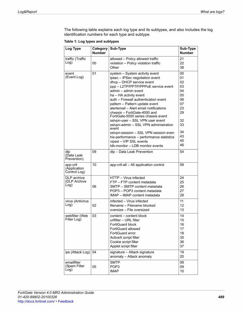
Log&Report What are logs?
F0h
The following table explains each log type and its subtypes, and also includes the log identification numbers for each type and subtype.
Table 1: Log types and subtypes
Log Type Category Number
Sub-Type Sub-Type Number
traffic (Traffic Log) 00
allowed – Policy allowed trafficviolation – Policy violation traffic Other
212238
event(Event Log)
01 system – System activity eventipsec – IPSec negotiation eventdhcp – DHCP service eventppp – L2TP/PPTP/PPPoE service eventadmin – admin eventha – HA activity eventauth – Firewall authentication eventpattern – Pattern update eventalertemail – Alert email notificationschassis – FortiGate-4000 and FortiGate-5000 series chassis event sslvpn-user – SSL VPN user eventsslvpn-admin – SSL VPN administration eventsslvpn-session – SSL VPN session evenhis-performance – performance statisticsvipssl – VIP SSL eventsldb-monitor – LDB monitor events
00010203040506072329
3233
34434546
dlp (Data Leak Prevention)
09 dlp – Data Leak Prevention 54
app-crtl (Application Control Log)
10 app-crtl-all – All application control 59
DLP archive(DLP Archive Log) 06
HTTP – Virus infectedFTP – FTP content metadataSMTP – SMTP content metadataPOP3 – POP3 content metadataIMAP – IMAP content metadata
2425262728
virus (Antivirus Log) 02
infected – Virus infectedfilename – Filename blockedoversize – File oversized
111213
webfilter (Web Filter Log)
03 content – content blockurlfilter – URL filterFortiGuard blockFortiGuard allowedFortiGuard errorActiveX script filterCookie script filterApplet script filter
1415161718353637
ips (Attack Log) 04 signature – Attack signatureanomaly – Attack anomaly
1920
emailfilter (Spam Filter Log)
05SMTPPOP3IMAP
080910
ortiGate Version 4.0 MR2 Administration Guide1-420-89802-20100326 489ttp://docs.fortinet.com/ • Feedback
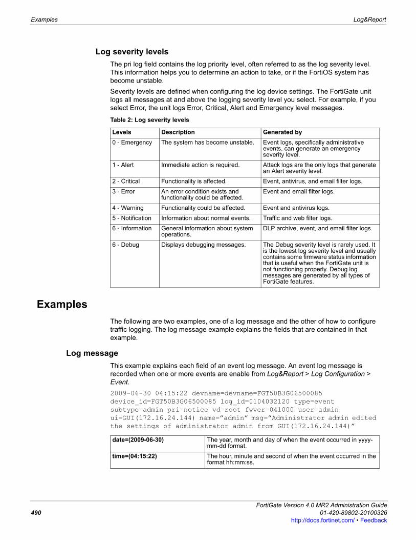
Examples Log&Report
Log severity levelsThe pri log field contains the log priority level, often referred to as the log severity level. This information helps you to determine an action to take, or if the FortiOS system has become unstable. Severity levels are defined when configuring the log device settings. The FortiGate unit logs all messages at and above the logging severity level you select. For example, if you select Error, the unit logs Error, Critical, Alert and Emergency level messages.
ExamplesThe following are two examples, one of a log message and the other of how to configure traffic logging. The log message example explains the fields that are contained in that example.
Log message This example explains each field of an event log message. An event log message is recorded when one or more events are enable from Log&Report > Log Configuration > Event. 2009-06-30 04:15:22 devname=devname=FGT50B3G06500085 device_id=FGT50B3G06500085 log_id=0104032120 type=event subtype=admin pri=notice vd=root fwver=041000 user=admin ui=GUI(172.16.24.144) name=”admin” msg=”Administrator admin edited the settings of administrator admin from GUI(172.16.24.144)”
Table 2: Log severity levels
Levels Description Generated by0 - Emergency The system has become unstable. Event logs, specifically administrative
events, can generate an emergency severity level.
1 - Alert Immediate action is required. Attack logs are the only logs that generate an Alert severity level.
2 - Critical Functionality is affected. Event, antivirus, and email filter logs.
3 - Error An error condition exists and functionality could be affected.
Event and email filter logs.
4 - Warning Functionality could be affected. Event and antivirus logs.
5 - Notification Information about normal events. Traffic and web filter logs.
6 - Information General information about system operations.
DLP archive, event, and email filter logs.
6 - Debug Displays debugging messages. The Debug severity level is rarely used. It is the lowest log severity level and usually contains some firmware status information that is useful when the FortiGate unit is not functioning properly. Debug log messages are generated by all types of FortiGate features.
date=(2009-06-30) The year, month and day of when the event occurred in yyyy-mm-dd format.
time=(04:15:22) The hour, minute and second of when the event occurred in the format hh:mm:ss.
FortiGate Version 4.0 MR2 Administration Guide490 01-420-89802-20100326
http://docs.fortinet.com/ • Feedback
Log&Report Examples
F0h
Logging all FortiGate trafficYou can use the following procedure to configure your FortiGate unit record traffic log messages for all traffic. This procedure enables traffic logging for all FortiGate interfaces that receive traffic. However, traffic logging may not log traffic that would otherwise be dropped by the FortiGate unit. To record log messages for this traffic, you can add an IPS Sensor that includes predefined IPS signatures that can detect and log traffic that would otherwise be dropped by the FortiGate unit.
To log all traffic received by a FortiGate unit1 Enter the following CLI command to enable logging of failed connection attempts to the
FortiGate unit that use TCP/IP ports other than the TCP/IP ports configured for management access:config system globalset localdeny enable
end
2 Enter the following CLI command to set global header checking to strict. config system globalset check-protocol-header strict
devname=(FGT50B3G06500085)
The name of the FortiGate unit. The name is either the default name (FGT<serial_number>) or the name given by an administrator. The name that appears in this field is the name that appears in Host Name in System > Status in the System Information widget.
device_id=(FGT50B3G06500085)
The serial number of the FortiGate unit.
log_id=(0104032120) A ten-digit number. The first two digits represent the log type and the following two digits represent the log subtype. The last five digits are the message id.
type=(event) The section of system where the event occurred.
subtype=(admin) The subtype of the log message. This represents a policy applied to the FortiGate feature in the firewall policy.
pri=(notice) The severity level of the event. There are six severity levels to specify. For more information, see “Log severity levels” on page 11.
vd=(root) The virtual domain where the traffic was logged.
fwver=(041000) The firmware version that was running when the log message was recorded.
user=(“admin”) The user’s admin profile, usually an administration user. In this example, the admin administrator changed the banned word.
ui=[GUI (172.16. 34.144)] The interface where this particular event occurred, along with the IP address of that interface. The ui field includes GUI, CLI, console, and LCD.
name=(“admin”) The user who created the traffic.
msg=(“Administrator admin edited the settings of administrator admin from GUI (172.16.24.144)”)
Explains the activity or event that the FortiGate unit recorded. In this example, an administrator edited the settings of the administrator admin from the web-based manager.
ortiGate Version 4.0 MR2 Administration Guide1-420-89802-20100326 491ttp://docs.fortinet.com/ • Feedback
Examples Log&Report
end
Strict header checking detects invalid raw IP packets by validating packet checksums and also checks IP headers to make sure they adhere to current standards. The default setting is loose which is usually appropriate for most environments. Loose header checking improves performance while meeting most organizations’ requirements.
3 Enter the following CLI commands to enable traffic logging for all of the FortiGate interfaces that receive traffic. The following commands enable traffic logging on port1 and port2. You should repeat these commands for all other FortiGate unit interfaces that receive traffic.config system interfaceedit port1set log enable
nextedit port2set log enable
end
4 Use the following command to enable logging of other traffic. This option is only available when logging to an external syslog server. RP: Commented this out because in 4.0 MR1, the other-traffic option is available for fortianalyzer, fortiguard, memory, and webtrends, as well as for syslog.config log syslogd filterset other-traffic enable
end
5 Go to UTM > Intrusion Protection > IPS Sensor and select Create New to add an IPS Sensor.Edit the IPS Sensor and select Add Pre-defined Override to add the following predefined IPS signatures to the sensor. • Invalid.Protocol.Header• TCP.Bad.Flags• TCP.Invalid.Packet.SizeEnable each of these signatures, set Action to Block and enable Logging.
6 Enter the following CLI commands to add a DoS policy (called an interface policy in the CLI) that includes the IPS Sensor.config firewall interface-policyedit 1set interface <interface_name>set srcaddr allset dstaddr allset service ANYset ips-sensor-status enableset ips-sensor <sensor_name>
end
Where <sensor_name> is the name of the IPS sensor added above.
FortiGate Version 4.0 MR2 Administration Guide492 01-420-89802-20100326
http://docs.fortinet.com/ • Feedback
Log&Report How a FortiGate unit stores logs
F0h
How a FortiGate unit stores logsThe type and frequency of log messages you intend to save determines the type of log storage to use. For example, if you want to log traffic and content logs, you need to configure the FortiGate unit to log to a FortiAnalyzer unit or syslog server. The FortiGate system memory is unable to log traffic and content logs because of their frequency and large file size. Storing log messages to one or more locations, such as a FortiAnalyzer unit or Syslog server, may be a better solution for your logging requirements than the FortiGate system memory. Configuring your FortiGate unit to log to a FortiGuard Analysis server may also be a better log storage solution if you do not have a FortiAnalyzer unit and want to create reports. This topic contains the following:• Remote logging to a FortiAnalyzer unit• Remote logging to the FortiGuard Analysis and Management Service• Remote logging to a syslog server• Local logging to memory• Local logging to disk
Remote logging to a FortiAnalyzer unitFortiAnalyzer units are network devices that provide integrated log collection, analysis tools and data storage. Detailed log reports provide historical as well as current analysis of network activity to help identify security issues and reduce network misuse and abuse.You can configure the FortiGate unit to log up to three FortiAnalyzer units. The FortiGate unit sends logs to all three FortiAnalyzer units. Each FortiAnalyzer unit stores the same information. Logging to multiple FortiAnalyzer units provides real-time backup protection in the event one of the FortiAnalyzer units fails. Configuring multiple FortiAnalyzer units is available only in the CLI.The FortiAnalyzer unit needs to be configured to receive logs from the FortiGate unit after you have configured log settings on the FortiGate unit. Contact a FortiAnalyzer administrator to complete the configuration.
Remote Logging & Archiving section of the Log Settings pageFortiAnalyzer Enables the FortiAnalyzer configuration settings.
IP Address The internal IP address of the FortiAnalyzer unit that you want to log to. Enter the IP address of the FortiAnalyzer unit in the field. When the IP address is entered, the Test Connectivity becomes available for testing the connection between the FortiAnalyzer unit and the FortiGate unit.
Test Connectivity Tests the connection between the two units. This is disabled until the IP address is entered in the IP address field. Select Test Connectivity to verify both units are successfully connected. Note: The test connectivity feature also provides a warning when a FortiGate unit requires a higher-end FortiAnalyzer unit or when the maximum number of VDOMs/FortiGate units has been reached on the FortiAnalyzer unit.
Minimum log level The minimum log level that logs will be logged at.
Note: You can specify the source IP address of self-originated traffic when configuring a FortiAnalyzer unit for logging; however, this is available only in the CLI.
ortiGate Version 4.0 MR2 Administration Guide1-420-89802-20100326 493ttp://docs.fortinet.com/ • Feedback

How a FortiGate unit stores logs Log&Report
Testing the FortiAnalyzer configurationAfter configuring FortiAnalyzer settings, test the connection between the FortiGate unit and FortiAnalyzer unit to verify both devices are communicating properly. During testing, the FortiGate unit displays information about specific settings for transmitting and receiving logs, reports, DLP archive and quarantine files. The FortiGate unit must learn the IP address of the FortiAnalyzer unit before testing the connection. A false test report failure may result if testing the connection occurs before the FortiGate unit learns the IP address of the FortiAnalyzer unit. You can test the connection status between the FortiGate unit and the FortiAnalyzer unit from the CLI using the following command syntax: execute log fortianalyzer test-connectivity
The command displays the connection status and the amount of disk usage in percent. For more information, see the FortiGate CLI Reference.
Remote logging to the FortiGuard Analysis and Management ServiceYou can configure logging to a FortiGuard Analysis server after registering for the FortiGuard Analysis and Management Service on the Fortinet support web site. Fortinet recommends verifying that the connection is working properly before configuring logging to a FortiGuard Analysis server. Remote logging to the FortiGuard Analysis server is similar to logging to a FortiAnalyzer unit because you can also enable archive logging. You can also use widgets to drill-down through information that was gathered from logs.
FortiAnalyzer(Hostname)
The name of the FortiAnalyzer unit. The default name of a FortiAnalyzer unit is its product name, for example, FortiAnalyzer-400.
FortiGate(Device ID)
The serial number of the FortiGate unit.
Registration Status
The status of whether or not the FortiGate unit is registered with the FortiAnalyzer unit. If the FortiGate unit is unregistered, it may not have full privileges. For more information, see the FortiAnalyzer Administration Guide.
Connection Status
The connection status between FortiGate and FortiAnalyzer units. A green check mark indicates there is a connection and a gray X indicates there is no connection.
Disk Space (MB) The amount of disk space, in MB, on the FortiAnalyzer unit for logs.
Allocated Space
The amount of the FortiAnalyzer unit hard drive space designated for logs, including quarantine files and DLP archives.
Used Space The amount of used space.
Total Free Space
The amount of unused space.
Privileges The permissions of the device for sending and viewing logs, reports, DLP archives, and quarantined logs.• Tx indicates the FortiGate unit is allowed to transmit log packets to the
FortiAnalyzer unit. • Rx indicates the FortiGate unit is allowed to display reports and logs stored
on the FortiAnalyzer unit.A check mark indicates the FortiGate unit has permissions to send or view log information and reports. An X indicates the FortiGate unit is not allowed to send or view log information.
Note: The test connectivity feature also provides a warning when a FortiGate unit requires a higher-end FortiAnalyzer unit or when the maximum number of VDOMs/FortiGate units has been reached on the FortiAnalyzer unit.
FortiGate Version 4.0 MR2 Administration Guide494 01-420-89802-20100326
http://docs.fortinet.com/ • Feedback
Log&Report How a FortiGate unit stores logs
F0h
Remote logging to a syslog serverA syslog server is a remote computer running syslog software and is an industry standard for logging. Syslog is used to capture log information provided by network devices. The syslog server is both a convenient and flexible logging device, since any computer system, such as Linux, Unix, and Intel-based Windows can run syslog software. When configuring logging to a syslog server, you need to configure the facility and the log file format, which is either normal or Comma Separated Values (CSV). The CSV format contains commas whereas the normal format contains spaces. Logs saved in the CSV file format can be viewed in a spread-sheet application, while logs saved in normal format are viewed in a text editor (such as Notepad) because they are saved as plain text files. Configuring a facility easily identifies the device that recorded the log file. You can choose from many different facility identifiers, such as daemon or local7. If you are configuring multiple Syslog servers, configuration is available only in the CLI. You can also enable the reliable delivery option for Syslog log messages in the CLI. From the FortiGate CLI, you can enable reliable delivery of syslog messages using the reliable option of the config log {syslog | syslog2 | syslog3} settings command. The FortiGate unit implements the RAW profile of RFC 3195 for reliable delivery of log messages. Reliable syslog protects log information through authentication and data encryption and ensures that the log messages are reliably delivered in the correct order. This feature is disabled by default.
Local logging to memoryThe FortiGate system memory has a limited capacity for log messages. The FortiGate system memory displays only the most recent log entries. It does not store traffic and content logs in system memory due to their size and the frequency of log entries. When the system memory is full, the FortiGate unit overwrites the oldest messages. All log entries are cleared when the FortiGate unit restarts.
Remote Logging & Archiving section of the Log Settings pageIP/FQDN The IP address or fully qualified domain name of the syslog server. For
example, the FQDN could be log.example.com.
Port The port number for communication with the syslog server, typically port 514.
Minimum log level The FortiGate unit logs all messages at and above the logging severity level you select. For more information about the logging levels, see “Log severity levels” on page 488.
Facility Facility indicates to the syslog server the source of a log message. By default, FortiGate reports Facility as local7. You may want to change Facility to distinguish log messages from different FortiGate units.
Enable CSV Format If you enable CSV format, the FortiGate unit produces the log in Comma Separated Value (CSV) format. If you do not enable CSV format the FortiGate unit produces plain text files.
Note: If more than one syslog server is configured, the syslog servers and their settings appear on the Log Settings page. You can configure multiple syslog servers in the CLI using the config log {syslog | syslog2 | syslog3} settings CLI command. For more information, see the FortiGate CLI Reference.
Note: You can specify the source IP address of self-originated traffic when configuring a Syslog server; however, this is available only in the CLI.
ortiGate Version 4.0 MR2 Administration Guide1-420-89802-20100326 495ttp://docs.fortinet.com/ • Feedback
How a FortiGate unit stores logs Log&Report
Local logging to diskIf your FortiGate unit contains a hard disk you can configure logging to disk. You can specify the minimum log level and how the FortiGate unit handles local logging if the hard disk becomes full. For local logs, the SQL log storage format is the default for all log types except content archiving and traffic logs. This is the only format from which you can generate reports. Archiving logs is not available in SQL format. You can enable SQL format logging for traffic logs, but this can cause some loss of logs because SQL format writing is slower than the compressed format.
Local archiving You can archive DLP and IPS packet logs to a FortiAnalyzer unit, local hard disk if applicable, and FortiGuard Analysis and Management Services if you have a subscription to it. Archiving is the historical storage of logs which can be accessed at any time, regardless of how old they are. Archived logs are located in Log&Report > Archive Access. Enabling archiving of these logs is configured within their own configuration. For example, when configuring a DLP rules or compound rules in a sensor, there is the Archive options within that rule to choose which type of archiving to have, either Full or Summary. The type of archiving is important since full archiving archives all information within the log message, which allows for email attachments if archiving emails, and summary archiving archives only the basic information.
Local Logging & Archiving section of the Log Settings pageMemory Stores logs on the FortiGate unit’s system memory.
Minimum log level The FortiGate unit logs all messages at and above the logging severity level you select. For more information about the logging levels, see “Log severity levels” on page 488.
Enable IPS Packet Archive
Enables archiving of IPS packet logs. Select to archive the IPS Packet logs.
Local Logging & Archiving section of the Log Settings pageDisk Stores local logs on the FortiGate unit’s hard disk.
Minimum log level The FortiGate unit logs all messages at and above the logging severity level you select. For more information about the logging levels, see “Log severity levels” on page 488.
When log disk is full The FortiGate unit will take the specified action, either to overwrite the oldest logs or stop logging altogether, when the disk is at the maximum capacity of storage space for logs. Select one of the following: Overwrite oldest logs – overwrites the oldest log message to continue logging. Stop logging – stops all logging when the disk is full.
Log rolling settings The settings of a log file.
Enable SQL Logging If you have an SQL database configured on your FortiGate unit, you can enable this feature to store logs on the SQL database. Select the ones you want to log to the SQL database:
Note: When you log to the SQL database, you can collect the log information and put that information into a report widget on Log&Report > Report > Executive Summary.
FortiGate Version 4.0 MR2 Administration Guide496 01-420-89802-20100326
http://docs.fortinet.com/ • Feedback
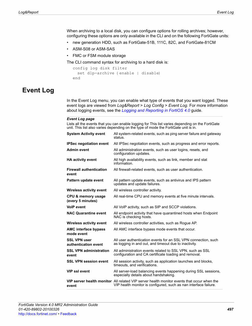
Log&Report Event Log
F0h
When archiving to a local disk, you can configure options for rolling archives; however, configuring these options are only available in the CLI and on the following FortiGate units: • new generation HDD, such as FortiGate-51B, 111C, 82C, and FortiGate-81CM• ASM-S08 or ASM-SAS• FMC or FSM module storageThe CLI command syntax for archiving to a hard disk is:
config log disk filterset dlp-archive {enable | disable}
end
Event LogIn the Event Log menu, you can enable what type of events that you want logged. These event logs are viewed from Log&Report > Log Config > Event Log. For more information about logging events, see the Logging and Reporting in FortiOS 4.0 guide.
Event Log pageLists all the events that you can enable logging for This list varies depending on the FortiGate unit. This list also varies depending on the type of mode the FortiGate unit is in.
System Activity event All system-related events, such as ping server failure and gateway status.
IPSec negotiation event All IPSec negotiation events, such as progress and error reports.
Admin event All administration events, such as user logins, resets, and configuration updates.
HA activity event All high availability events, such as link, member and stat information.
Firewall authentication event
All firewall-related events, such as user authentication.
Pattern update event All pattern update events, such as antivirus and IPS pattern updates and update failures.
Wireless activity event All wireless controller activity.
CPU & memory usage (every 5 minutes)
All real-time CPU and memory events at five minute intervals.
VoIP event All VoIP activity, such as SIP and SCCP violations.
NAC Quarantine event All endpoint activity that have quarantined hosts when Endpoint NAC is checking hosts.
Wireless activity event All wireless controller activities, such as Rogue AP.
AMC interface bypass mode event
All AMC interface bypass mode events that occur.
SSL VPN user authentication event
All user authentication events for an SSL VPN connection, such as logging in and out, and timeout due to inactivity.
SSL VPN administration event
All administration events related to SSL VPN, such as SSL configuration and CA certificate loading and removal.
SSL VPN session event All session activity, such as application launches and blocks, timeouts, and verifications.
VIP ssl event All server-load balancing events happening during SSL sessions, especially details about handshaking.
VIP server health monitor event
All related VIP server health monitor events that occur when the VIP health monitor is configured, such as nan interface failure.
ortiGate Version 4.0 MR2 Administration Guide1-420-89802-20100326 497ttp://docs.fortinet.com/ • Feedback
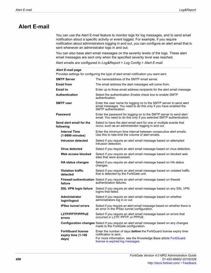
Alert E-mail Log&Report
Alert E-mailYou can use the Alert E-mail feature to monitor logs for log messages, and to send email notification about a specific activity or event logged. For example, if you require notification about administrators logging in and out, you can configure an alert email that is sent whenever an administrator logs in and out. You can also base alert email messages on the severity levels of the logs. These alert email messages are sent only when the specified severity level was reached. Alert emails are configured in Log&Report > Log Config > Alert E-mail.
Alert E-mail pageProvides settings for configuring the type of alert email notification you want sent.
SMTP Server The name/address of the SMTP email server.
Email from The email address the alert messages will come from.
Email to Enter up to three email address recipients for the alert email message.
Authentication Select the authentication Enable check box to enable SMTP authentication.
SMTP user Enter the user name for logging on to the SMTP server to send alert email messages. You need to do this only if you have enabled the SMTP authentication.
Password Enter the password for logging on to the SMTP server to send alert email. You need to do this only if you selected SMTP authentication.
Send alert email for the following
Select to have the alert email sent for one or multiple events that occur, such as an administrator logging in and out.
Interval Time (1-9999 minutes)
Enter the minimum time interval between consecutive alert emails. Use this to rate-limit the volume of alert emails.
Intrusion detected Select if you require an alert email message based on attempted intrusion detection.
Virus detected Select if you require an alert email message based on virus detection.
Web access blocked Select if you require an alert email message based on blocked web sites that were accessed.
HA status changes Select if you require an alert email message based on HA status changes.
Violation traffic detected
Select if you require an alert email message based on violated traffic that is detected by the FortiGate unit.
Firewall authentication failure
Select if you require an alert email message based on firewall authentication failures.
SSL VPN login failure Select if you require an alert email message based on any SSL VPN logins that failed.
Administrator login/logout
Select if you require an alert email message based on whether administrators log in or out.
IPSec tunnel errors Select if you require an alert email message based on whether there is an error in the IPSec tunnel configuration.
L2TP/PPTP/PPPoE errors
Select if you require an alert email message based on errors that occurred in L2TP, PPTP, or PPPoE.
Configuration changes Select if you require an alert email message based on any changes made to the FortiGate configuration.
FortiGuard license expiry time (1-100 days)
Enter the number of days before the FortiGuard license expiry time notification is sent. For more information, see the Knowledge Base article FortiGuard license is expired log messages.
FortiGate Version 4.0 MR2 Administration Guide498 01-420-89802-20100326
http://docs.fortinet.com/ • Feedback
Log&Report Accessing and viewing log messages
F0h
Accessing and viewing log messagesThe Log Access menu provides tabs for viewing logs according to the logging locations you specified, such as Remote (for example FortiAnalyzer) or local logging to disk (Disk). Each tab provides options for viewing log messages, such as search and filtering options, and choice of log type. The Remote tab displays logs stored on either the FortiGuard Analysis server or FortiAnalyzer unit, whichever one is configured for logging. You can access log files stored on the FortiGuard Analysis server from the FortiGate web-based manager, if you have subscribed to FortiGuard Analysis and Management Service. After enabling logging to the FortiGuard Analysis server, a Remote tab appears in the Log Access menu. For more information about viewing real-time and historical log files, see the FortiGuard Analysis and Management Service Guide. When viewing log information, you can select a row and view that log message’s information within a table, which appears on the side of the page. Within this table, you can clearly see each field that is in that particular log message. This table is available only when viewing logs in Format. The columns that appear reflect the content found in the log file. The top portion of the Log Access page includes navigational features to help you move through the log messages and locate specific information. You can also customize the columns so that specific information is displayed. For example, log messages can be viewed in Formatted or Raw view. In Formatted view, you can customize the columns, or filter log messages. In Raw view, the log message appears as it would in the log file. For more information about filtering log messages, see “Adding filters to web-based manager lists” on page 33. For more information about customizing columns, see “Using column settings to control the columns displayed” on page 35. Filtering is also another way to customize the display of log messages. By using the filter icon, you can display specific information of log messages. For example, you may want to display only event log messages that have a severity level of alert. From Log&Report > Log Access, the following tabs are available depending on the log device configured:• Remote to view log messages stored on a FortiAnalyzer unit or the FortiGuard
Analysis and Management Service• Memory to view log messages stored in FortiGate unit system memory• Disk to view log messages stored on a hard disk such as an internal hard disk or an
AMC hard disk, as well as SQL logs.
FortiGuard log quota usage
Select if you require an alert email message based on the FortiGuard Analysis server log disk quota getting full.
Disk Usage Select if you require an alert email when the internal hard disk or AMC disk reaches a disk usage level. You can set the disk usage level at which the alert email is sent.
Send alert email for logs based on severity
Select if you want to send an alert email that is based on a specified log severity, such as warning.
Minimum log level Select a log severity from the list. For more information about log severity levels, see “Log severity levels” on page 488.
Note: You can specify the source IP address of self-originated traffic for an alert email message, however, this is available only in the CLI.
ortiGate Version 4.0 MR2 Administration Guide1-420-89802-20100326 499ttp://docs.fortinet.com/ • Feedback
Archived logs Log&Report
Archived logsYou can view many archive log types including DLP archives or IPS Packet archives from the FortiGate unit. Archives are historical logs that are stored on a log device that supports archiving, such as the FortiAnalyzer unit.These logs are accessed from Log&Report > Archive Access . If you subscribed to the FortiGuard Analysis and Management Service, you can also view log archives from there as well. The DLP Archive menu is only visible if:• You have configured the FortiGate unit for remote logging and archiving to a
FortiAnalyzer unit. See “Remote logging to a FortiAnalyzer unit” on page 491.• You have subscribed to the FortiGuard Analysis and Management Service. See the
FortiGuard Analysis and Management Service Administration Guide.The following menus are available when you are viewing DLP archives for one of these protocols.• E-mail to view POP3, IMAP, SMTP, POP3S, IMAPS, SMTPS, and spam email
archives.• Web to view HTTP and HTTPS archives.• FTP to view FTP archives.• IM to view AIM, ICQ, MSN, and Yahoo! archives.• VoIP to view session control (SIP, SIMPLE and SCCP) archives.If you need to view log archives in Raw format, select Raw beside Formatted.
The following appears on the Archive Access and Log Access pages when viewing each log type’s log messagesLog Type Select the type of log you want to view. Some log files, such as the traffic log,
cannot be stored to memory due to the volume of information logged.
Page Controls By default, the first page of the list of items is displayed. The total number of pages displays after the current page number. For example, if 3/54 appears, you are currently viewing page 3 of 54 pages.To view pages, select the left and right arrows to display the first, previous, next, or last page. To view a specific page, enter the page number in the field and then press Enter. For more information, see “Using page controls on web-based manager lists” on page 34.
Column Settings Select to add or remove columns. This changes what log information appears in Log Access.
Raw or Formatted By default, log messages are displayed in Formatted mode. Select Formatted to view log messages in Raw mode, without columns. When in Raw mode, select Formatted to switch back to viewing log messages organized in columns. When log messages are displayed in Formatted view, you can customize the columns, or filter log messages.
Clear All Filters Clear all filter settings.
Note: The FortiAnalyzer unit must be running firmware version 3.0 or higher to view logs from the FortiGate unit.
FortiGate Version 4.0 MR2 Administration Guide500 01-420-89802-20100326
http://docs.fortinet.com/ • Feedback
Log&Report Quarantine
F0h
Quarantine Within the Log Access menu, you can view detailed information about each quarantined file. The information can either be sorted or filtered, depending on what you want to view. Sort the files by file name, date, service, status, duplicate count (DC), or time to live (TTL). Filter the list to view only quarantined files with a specific status or from a specific service.On Log&Report > Archive Access > Quarantine, the file quarantine list displays the following information about each quarantined file:
Quarantine pageLists all files that are considered quarantined by the FortiGate unit. On this page you can filter information so that only specific files are displayed on the page.
Source Either FortiAnalyzer or Local disk, depending where you configure to quarantined files to be stored.
Sort by Sort the list. Choose from: Status, Service, File Name, Date, TTL, or Duplicate Count. Select Apply to complete the sort.
Filter Filter the list. Choose either Status (infected, blocked, or heuristics) or Service (IMAP, POP3, SMTP, FTP, HTTP, IM, or NNTP). Select Apply to complete the filtering. Heuristics mode is configurable through the CLI only.If your FortiGate unit supports SSL content scanning and inspection Service can also be IMAPS, POP3S, SMTPS, or HTTPS. For more information, see the UTM chapter of the FortiOS Handbook.
Apply Select to apply the sorting and filtering selections to the list of quarantined files.
Delete Select to delete the selected files.
Page Controls Use the controls to page through the list. For more information, see “Using page controls on web-based manager lists” on page 34.
Remove All Entries
Removes all quarantined files from the local hard disk. This icon only appears when the files are quarantined to the hard disk.
File Name The file name of the quarantined file.
Date The date and time the file was quarantined, in the format dd/mm/yyyy hh:mm. This value indicates the time that the first file was quarantined if duplicates are quarantined.
Service The service from which the file was quarantined (HTTP, FTP, IMAP, POP3, SMTP, IM, NNTP, IMAPS, POP3S, SMTPS, or HTTPS).
Status The reason the file was quarantined: infected, heuristics, or blocked.
Status Description
Specific information related to the status, for example, “File is infected with “W32/Klez.h”” or “File was stopped by file block pattern.”
DC Duplicate count. A count of how many duplicates of the same file were quarantined. A rapidly increasing number can indicate a virus outbreak.
TTL Time to live in the format hh:mm. When the TTL elapses, the FortiGate unit labels the file as EXP under the TTL heading. In the case of duplicate files, each duplicate found refreshes the TTL.The TTL information is not available if the files are quarantined on a FortiAnalyzer unit.
Upload status Y indicates the file has been uploaded to Fortinet for analysis, N indicates the file has not been uploaded. This option is available only if the FortiGate unit has a local hard disk.
Download Select to download the corresponding file in its original format.This option is available only if the FortiGate unit has a local hard disk.
Submit Select to upload a suspicious file to Fortinet for analysis.This option is available only if the FortiGate unit has a local hard disk.
ortiGate Version 4.0 MR2 Administration Guide1-420-89802-20100326 501ttp://docs.fortinet.com/ • Feedback
Reports Log&Report
ReportsReports provide an easy way to analyze and view the information from logs. A report is a collection of log information, which is then displayed in the report in the form of text, graphs and tables. You can configure the following reports: • FortiOS FortiGate reports – provides configuration of a report schedule as well as
cloned report• Executive Summary reports – widgets that display collected log information from the
SQL database; limited configuration settings• Basic traffic reports – collected log information from the FortiGate unit’s system
memory, which displays as a bar chart. FortiOS reports are available only on FortiGate units that contain local hard drives. You also require enabling the following in the CLI so that the Report menu appears in the web-based manager:
config log fortianalyzer settingset gui-display enable
end
This topic contains the following: • FortiOS reports• Executive Summary reports from SQL logs
FortiOS reportsFortiOS reports are configured from logs stored on the FortiGate unit's hard drive and generated by the FortiGate unit as well. This provides a central location to create and store reports generated from logs files, since previously this feature was only available on FortiAnalyzer units. FortiOS reports are configured in Log&Report > Report Config.
You need to enable the report menus before you can configure reports. Report Config and Report Access are enabled in the CLI. The following is the command syntax you need to use to enable Report Config and Report Access menus in the web-based manager.
config log fortianalyzer settingset gui-display enable
end
ThemesA theme allows you to configure how the information displays on the page, as well as the type of font, page orientation, and if there will be multiple columns. A theme for a report is configured in Log&Report > Report Config > Theme.
Note: Duplicates of files (based on the checksum) are not stored, only counted. The TTL value and the duplicate count are updated each time a duplicate of a file is found.
Note: FortiOS reports are available only on FortiGate units with loca hard drives. If upgrading from FortiOS 4.0 MR1 or earlier, FortiAnalyzer reports will only be available on the FortiAnalyzer unit and no configuration settings for FortiAnalyzer reports is supported in FortiOS 4.0 MR2.
FortiGate Version 4.0 MR2 Administration Guide502 01-420-89802-20100326
http://docs.fortinet.com/ • Feedback
Log&Report Reports
F0h
LayoutsA report layout, similar to the layout that you must configure for a FortiAnalyzer report, contains settings for including charts, sections, adding images and scheduling when the layout will be generated. The Report Components section on the Add Report Layout page provides a place where you can view what charts, sections, and images you have chosen for that report. This section also allows you to move the parts, such as charts, to where you want them in the report. A report layout is configured in Log&Report > Report Config > Layout.
Theme pageLists all the charts, both default and the ones that you created. On this page, you can edit, delete and create new charts.
Create New When you create a new theme, you are automatically redirected to the Report Title page.
Edit Select to modify settings of an existing chart.
Delete Select to remove a chart from the list.
Name The name of the theme.
Column Count The number of columns that will be applied within the report. You can have up to three columns.
Report Title page Provides settings for configuring a theme for a report.
Name Enter a name for the theme.
Page Layout Select the type of page orientation, either Portrait or Landscape.
Column Count Select how many columns for the report. You can have up to three columns per page.
Report Title Choose the appearance of the report’s title. Select from the following: Font – the type of font you want to use, and whether it should be bold, italic or both. Size– the font’s sizeColor – the color of the font; you choose by selecting the color block and then a color palette appears and you can choose the color from the palette. Align – the alignment of the title, subtitle, heading, or normal paragraph text. The options for choosing the appearance of the report’s title are the same for the subtitle, heading 1 through 3, and normal.
Subtitle Choose the appearance of the subtitle.
Heading 1 ‘Choose the appearance of the Heading 1 section titles.
Heading 2 Choose the appearance of the Heading 2 section titles.
Heading 3 Choose the appearance of the Heading 3 section titles.
Normal Choose the appearance of the text that appears in the paragraphs.
Layout pageLists all the report layouts that you configured, as well as default layouts. On this page, you can edit, delete, clone a report, or create a new report.
Create New When you select Create New, you are automatically redirected to the Add Report Layout page.
Edit Select to modify a report layout’s settings.
Delete Select to remove a report layout from the list.
Clone Use to base a new report layout on an existing one.
Run Immediately generates a report.
ortiGate Version 4.0 MR2 Administration Guide1-420-89802-20100326 503ttp://docs.fortinet.com/ • Feedback
Reports Log&Report
ChartsThere are default charts available when configuring a report layout; however, you can configure your own charts for report layouts that you can create for report layouts. When configuring charts, you must also configure datasets because they are used to gather specific data from the SQL database. You should configure the datasets you need for a report layout first, and then configure chart.
Report Layout The name of the report layout.
Title The name of the title that appears on the generated report.
Format The type of format that the report is in, either PDF or HTML.
Schedule The time that the report is generated on.
Description A description about the report.
Add Report Layout pageProvides settings for configuring a report layout.
Name Enter a name of the report layout. This is not the name that will be the report’s title.
Report Theme Select a theme from the drop-down list.
Description Enter a description, if you want, to explain what the report is about. This does not appear within the report.
Output Format The type of format the report will be generated in. You can choose PDF to have the report generated as a PDF.
Schedule Select what type of schedule you want the report generated on. The type of schedule can be on a daily basis, weekly, on demand (whenever you want), or only once. If you select On Demand, the report can be generated whenever you want it. If you select Once, the report is generated as soon as the report is saved.
Title Enter a name for the title of the report.
Sub Title Enter a name that will be the sub title of the report.
Option Select to include all or some of the following report options: Table of Contents – includes a table of contents in the reportAuto Heading Number – automatically provides a heading number for each heading, in numerical format. HTML navigation bar – provides a navigational bar to help you navigate in report whose format is HTMLChart Name as Heading – allows for a chart’s name to be the heading
Report Components
Select Add to add the type of information that you want in the report. These components are required since they contain what log information needs to be included in the report, and how that information will be displayed and formatted in the report. This section provides a preview in the sense that tit allows you to edit each part of the report, such as a chart or an image. You can move each part to be in the order that you want it within the generated report.
Add Component pageText Select the type of format the heading will have. For example, if you select
Heading 1, the headings will be in the Heading 1 format. When you select Normal, you will be providing a comment for a section within the report.
Chart Select a category from the Categories drop-down list. Each category contains different charts that are specific to that category.
Image Select an image to include within the report.
Misc Select a page break, column break, or horizontal line to include in the report.
FortiGate Version 4.0 MR2 Administration Guide504 01-420-89802-20100326
http://docs.fortinet.com/ • Feedback
Log&Report Reports
F0h
You must have prior knowledge about SQL before configuring datasets because datasets require SQL statements. Datasets are configured only in the CLI. A chart is configured in Log&Report > Report Config > Chart.
ImagesYou can import an image to use for a report. The image formats that are supported are JPEG, JPG and PNG.
Chart pageLists all the charts, both default and the ones that you created. On this page, you can edit, delete and create new charts.
Create New When you create a new chart, you are automatically redirected to the Add Graph Report Chart page.
Edit Select to modify settings of an existing chart.
Delete Select to remove a chart from the list.
Name The name of the chart.
Type The type of information that will display within the chart. For example, a bar chart displays attack log information in the Attacks_February chart.
Dataset The dataset that will be used for the chart.
Comments The description about the chart.
Add Graph Report Chart page Provides settings for configuring charts for report layouts.
Name Enter a name for the chart.
Dataset Select a configured dataset for the chart.
Category Select a log category for the chart.
Comments Enter a comment to describe the chart. This is optional.
Graph Type Select the type of graph that will display the information within the chart. If you select Pie, only Category Series and Value Series appears.
Category Series Enter the fields for the category in the Databind field. The databind is a combination of the fields derived rom the SQL statement or named fields in the CLI. For example, field(3).
Value Series Enter the fields for the value in the Databind field. The databind is a combination of the fields derived rom the SQL statement or named fields in the CLI. For example, field(3).
X-series The settings for the x axis of the line, bar or flow chart.
Databind Enter an SQL databind value expression for binding data to the series being configured. For example, field(3).
Category Axis Select to have the axis show the type of log category. The default is no log category will appear on the axis.
Scale Sets the type of format to display the date and time on the x axis.
Format Choose the type of time format that displays on the x axis.
Number of Step Choose the number of steps on the horizontal axis of the graph.
Step Enter the number of scale units in each x axis scale step.
Unit Select the unit of the scale-step on the x-axis.
Y-series The Y-series settings to configure the y part of the line, bar or flow chart.
Databind Enter the fields for the x-series. The databind is a combination of the fields derived rom the SQL statement or named fields in the CLI. For example, field(3).
Group Enter a group in the field.
ortiGate Version 4.0 MR2 Administration Guide1-420-89802-20100326 505ttp://docs.fortinet.com/ • Feedback
Reports Log&Report
Images are imported in Log&Report > Report Config > Image.
Viewing generated FortiOS reportsAfter creating a report layout, you can go to the Report Access > Disk to view your generated report. When you choose to generate a report only once, the report is generated right away.
Executive Summary reports from SQL logsOn FortiGate units that contain a hard drive, you can display Executive Summary reports based on logs stored in an SQL database. The log messages are stored in text format in the database. There are many default reports that you can select and customize in the web-based manager. You can customize reports by selecting the report update schedule and location in the Executive Summary. Executive summary reports are configured in Log&Report > Report Access > Executive Summary.
Image pageLists all the images that you have imported. On this page, you can delete an image, import an image from your local PC, or view an image.
Delete Remove an image from the list on the page.
Import Import an image from your local PC.
View Displays the image. When you select View, you are automatically redirected to the View Image page where the image displays. Select Return to go back to the Image page.
Image Name The file name of the image.
Thumbnail A thumbnail image of the actual image you imported.
Import Image File page Provides settings for importing images.
File to Import Enter the location of the image on the local PC or select Browse to locate the image file. Select OK to start importing the image file.
Disk pageLists all the reports that are generated by the FortiGate unit. You can also remove reports from the list.
Delete Select to remove a report from the list.
Report File The report name that the FortiGate unit gave the report. This name is in the format <scheduletype>-<report_title>-<yyyy-mm-dd>-<start_time>. For example, Once-examplereport_1-2010-02-12-083054, which indicates that the report titled examplereport_1 was scheduled to generate only once and did on February 12, 2010 at 8:30 am. The hour format is in hh:mm:ss format.
Started The time when the report began generating. The format is in yyyy-mm-dd hh:mm:ss.
Finished The time when the report finished generating. The format is in yyyy-mm-dd hh:mm:ss.
Size The size of the report after it was generated. The size is in bytes.
Other Formats The other type of format you choose the report to be in, for example, PDF. When you select PDF in this column, the PDF opens up within the Disk page. You can save the PDF to your local PC when it is opened on the Disk page as well.
FortiGate Version 4.0 MR2 Administration Guide506 01-420-89802-20100326
http://docs.fortinet.com/ • Feedback
Log&Report Reports
F0h
FortiAnalyzer report schedulesFortiAnalyzer report schedules are available only when a FortiAnalyzer unit is configured for logging purposes. A report layout is required before configuring a report schedule, so contact a FortiAnalyzer administrator before configuring report schedules from the FortiGate unit to verify that the appropriate report layout is configured. Report layouts can only be configured from the FortiAnalyzer unit. For information about how to configure a report layout, see the FortiAnalyzer Administration Guide.You need to enable the report menus before configuring reports. Report Config and Report Access are enabled in the CLI. The following is the command syntax you need to use to enable Report Config and Report Access menus in the web-based manager.
config log fortianalyzer settingset gui-display enable
end
FortiAnalyzer report schedules are configured in Log&Report > Report Config > FortiAnalyzer.
FortiAnalyzer pageLists all report schedules that you created. On this page, you can edit, delete or create a new report schedule.
Create New Create a new report schedule.
Name The name of the report schedule.
Description The comment made when the report schedule was created.
Report Layout The name of the report layout used for the report schedule.
Schedule When the report schedule will be generated. The time depends on what time period was selected when the report schedule was created: once, daily, or specified days of the week.For example, if you select monthly, the days of the month and time (hh:mm) will appear in the format Monthly 2, 10, 21, 12:00.
Delete and Edit icons Delete or edit a report schedule in the list.
Clone icons Create a duplicate of the report schedule and use it as a basis for a new report schedule.
Create Schedule Settings pageProvides settings for configuring a report schedule. You require a report layout when configuring a report schedule.
Name Enter a name for the schedule.
Description Enter a description for the schedule. This is optional.
Report Layout Select a configured report layout from the list. You must apply a report layout to a report schedule. For more information, see the FortiAnalyzer Administration Guide.
Language Select the language you want used in the report schedule from the list.
Schedule Select one of the following to have the report generate once only, daily, weekly, or monthly at a specified date or time period.
Once Select to have the report generated only once.
Daily Select to generate the report every date at the same time, and then enter the hour and minute time period for the report. The format is hh:mm.
These Days Select to generate the report on specified days of the week, and then select the days of the week check boxes.
ortiGate Version 4.0 MR2 Administration Guide1-420-89802-20100326 507ttp://docs.fortinet.com/ • Feedback
Reports Log&Report
These Dates Select to generate the report on a specific day or days of the month, and then enter the days with a comma to separate them. For example, if you want to generate the report on the first day, the 21st day and 30th day, enter: 1, 21, 30.
Log Data Filtering You can specify the following variables for the report:
Virtual Domain Select to create a report based on virtual domains. Enter a specific virtual domain to include in the report.
User Select to create a report based on a network user. Enter the user or users in the field, separated by spaces. If a name or group name contains a space, if should be specified between quotes, for example, “user 1”.
Group Select to create a report based on a group of network users, defined locally. Enter the name of the group or groups in the field.
LDAP Query Select the LDAP Query check box and then select an LDAP directory or Windows Active Directory group from the list.
Time Period Select to include the time period of the logs to include in the report.
Relative to Report Runtime
Select a time period from the list. For example, this year.
Specify Select to specify the date, day, year and time for the report to run. From – Select the beginning date and time of the log time range. To – Select the ending date and time of the log time range.
Output Select the format you want the report to be in and if you want to apply an output template.
Output Types Select the type of file format for the generated report. You can choose from PDF, MS Word, Text, and MHT.
Email/Upload Select the check box if you want to apply a report output template from the list. This list is empty if a report output template does not exist. For more information, see the FortiAnalyzer Administration Guide.
Note: If you have VDOMs enabled, FortiAnalyzer reports are accessible only in each VDOM, not in the global VDOM.
FortiAnalyzer reports do not appear if the FortiGate unit is not connected to a FortiAnalyzer unit, or if the FortiAnalyzer unit is not running firmware 3.0 or higher.
FortiGate Version 4.0 MR2 Administration Guide508 01-420-89802-20100326
http://docs.fortinet.com/ • Feedback
Index
F0h
IndexSymbols_email, 22_fqdn, 22_index, 22_int, 22_ipv4, 22_ipv4/mask, 22_ipv4mask, 22_ipv6, 22_ipv6mask, 22_name, 22_pattern, 22_str, 22_v4mask, 22
_v6mask, 22
Numerics802.3ad aggregate interface
creating, 96
Aaccept action
firewall policy, 445, 446access profile, See admin profile, 181action
firewall policy, 266active sessions
HA statistics, 139
ortiGate Version 4.0 MR2 Administration Guide1-420-89802-20100326 509ttp://docs.fortinet.com/ • Feedback
Index
adding, configuring or definingadmin profile, 181administrative access to interface, 101administrator account, 169administrator password, 170administrator settings, 183authentication settings, 465authentication, firewall policy, 270BFD, 257BFD on BGP, 258BFD on OSPF, 258CA certificates, 194Certificate Revocation List (CRL), 195cipher suite, 431combined IP pool and virtual IP, 328custom signatures, 372DHCP interface settings, 98DHCP relay agent, 132DHCP server, 132Directory Service server, 457, 458Directory Service user groups, 462Dynamic DNS on an interface, 99dynamic virtual IP, 323firewall address, 295firewall address group, 296firewall policy, 265, 266, 335, 336firewall policy, modem connections, 111firewall schedule, 307firewall user groups, 461firewall virtual IP, 311firmware version, 42FortiAnalyzer report schedules, 505FortiWiFi-50B settings, 124, 125FortiWiFi-60B settings, 124, 125gateway for default route, 234HA, 135HA device priority, 139HA subordinate unit host name, 139health check monitor, 342interface settings, 92inter-VDOM links, 83IP pool, 328IPSec encryption policy, 273IPSec VPN phase 1, 414IPSec VPN phase 1 advanced options, 415IPSec VPN phase 2, 417IPSec VPN phase 2 advanced options, 418IPv6 support, 185LDAP authentication, 173LDAP server, 453, 454license key, 214local user account, 450logging to a FortiAnalyzer unit, 491logging to a FortiGuard Analysis server, 492logging to a Syslog server, 493logging to memory, 493MAC filter list, 127modem connections, firewall policy, 111modem interface, 107MTU size, 103NAT virtual IP, 317network options, 112OCSP certificates, 194one-time schedule, 308
OSPF areas, 251OSPF AS, 248OSPF basic settings, 248OSPF interface, operating parameters, 252OSPF networks, 252OSPF settings, advanced, 250override server, 208password, 170password, administrator, 170peer users and peer groups, 459PKI authentication, 176policy, 266, 270PPPoE or PPPoA interface settings, 99PPTP range, 425, 426PPTP VPN, 425, 426push updates, 210RADIUS authentication, 171RADIUS server, 452recurring schedule, 308redundant interface, 97redundant mode, 110remote authentication, 171RIP settings, advanced, 246RIP-enabled interface, 247scripts, 213secondary IP address, 103server load balance port forwarding virtual IP, 348server load balance virtual IP, 344SNMP community, 141SSL VPN options, firewall policy, 274SSL VPN settings, 430SSL VPN user groups, 462standalone mode, 110static NAT port forwarding, IP address and port range, 321static NAT port forwarding, single address and port, 320static NAT virtual IP, IP address range, 318static route, adding to routing table, 234system administrators, 167system certificates, 192system configuration backup and restore, 200system configuration backup and restore, FortiManager,
200system configuration, central management options, 201system time, 41TACACS+ authentication, 175TACACS+ server, 456updates for FDN and FortiGuard services, 203URL filter list, 380, 381user authentication settings, 465user group, 463user groups, 460VDOM configuration settings, 75, 81VDOM configuration settings, advanced, 78VDOM configuration settings, global, 76VDOM interface, 82VDOM, new, 80VIP group, 325virtual IP, 315virtual IP group, 325virtual IP, port translation only, 324virtual IPSec interface, 100VPN firewall policy-based internet browsing, 422VPN route-based internet browsing, 422wireless interface, 125
FortiGate Version 4.0 MR2 Administration Guide510 01-420-89802-20100326
http://docs.fortinet.com/ • Feedback
Index
F0h
zone, 107address
firewall address group, 296list, 295
address group, 296adding, 296creating new, 296list, 296
Address Namefirewall address, 295
adminadministrator account, 27
admin profileadministrator account, 178CLI commands list, 179configuring, 181viewing list, 181
administrative accesschanging, 27interface settings, 94, 100, 104monitoring logins, 184
administrative distance, 228administrative interface. See web-based manageradministrator
assigning to VDOM, 84administrator account
admin, 27admin profile, 178configuring, 169netmask, 170
administrator logindisclaimer, 158
administrator passwordchanging, 27
administrator settings, 183administrators
viewing list, 169administrators, monitoring, 184Advanced Mezzanine Card (AMC), 45AFS3, advanced file security encrypted file
AFS3, 299agent
sFlow, 105aggregate interface
creating, 96AH, predefined service, 299alert email, 496
options, 496SMTP user, 496
alert message consoleviewing, 47
allow inboundIPSec firewall policy, 273
allow outboundIPSec firewall policy, 273
AMCbridge module, 218configuring AMC modules, 217
AMC module, 91configuring, 217
antispamport 53, 206port 8888, 206
antispam. See also Email filter, 386antivirus
quarantine files list, 499virus list, 363
antivirus and attack definitions, 207antivirus updates, 208
manual, 44through a proxy server, 209
ANYservice, 299
AOLservice, 299
application control, 405area border router (ABR), 251ARP, 315, 338
proxy ARP, 315, 338AS
OSPF, 248ASM-CX4, 218ASM-cx4, 218ASM-FX2, 218attack updates
manual, 44scheduling, 208through a proxy server, 209
AuthenticationIPSec VPN, phase 2, 418
authenticationCitrix, 118client certificates and SSL VPN, 431configuring remote authentication, 171defining settings, 465explicit web proxy, 118firewall policy, 270HTTP, 118MD5, 252NAT device, 118proxy, 118RIP, 248server certificate and SSL VPN, 431web proxy, 118Windows Terminal Server, 118
Authentication AlgorithmIPSec VPN, manual key, 420, 421
Authentication KeyIPSec VPN, manual key, 421
Authentication MethodIPSec VPN, phase 1, 415
Auto KeyIPSec VPN, 413
Autokey Keep AliveIPSec VPN, phase 2, 419
autonomous system (AS), 254
Bback to HA monitor
HA statistics, 138
ortiGate Version 4.0 MR2 Administration Guide1-420-89802-20100326 511ttp://docs.fortinet.com/ • Feedback

Index
backing up3.0 config to FortiUSB, 633.0 configuration, 62config using web-based manager, 3.0, 62
backup (redundant) modemodem, 107
backup and restore, system maintenance, 200backup mode
modem, 110band
wireless setting, 124bandwidth
guaranteed, 335maximum, 336, 440, 443
banned wordcharacter set, 379
banned word (email filter)catalog, 389
banned word (spam filter)list, 391
banned word list catalogviewing, 389
beacon intervalwireless setting, 124
BFDconfiguring on BGP, 258configuring on OSPF, 258disabling, 258
BGPAS, 254RFC 1771, 254service, 299
blackhole route, 229blackhole routing, 95bridge mode, 218bridge module
AMC, 218
CCA certificates
importing, 194viewing, 194
catalogbanned word, 389content filter, 376IP address black/white list, 391URL filter, 380
central management, 182revision control, 183
Certificate NameIPSec VPN, phase 1, 415
certificate, security. See system certificatecertificate, server, 431certificate. See system certificateschannel
wireless setting, 124character set
converting, 379DLP, 379email filter, 379web filtering, 379
CIDR, 22, 187, 293, 443cipher suite
SSL VPN, 431Citrix
authentication, 118CLI, 25
admin profile, 179connecting to from the web-based manager, 28
CLI commandPPTP tunnel setup, 426
CLI configurationusing in web-based manager, 50web category block, 384
CLI console, 50client certificates
SSL VPN, 431client comforting, 378cluster member, 137
cluster members list, 138priority, 138role, 138
cluster unitdisconnecting from a cluster, 139
collectorsFlow, 105
column settingsconfiguring, 35using with filters, 35
comfortingclient, 378
command line interface (CLI), 18comments
firewall policy, 270comments, documentation, 24concentrator
equivalent for route-based VPN, 413IPSec tunnel mode, 422IPSec VPN, policy-based, 422
Concentrator NameIPSec VPN, concentrator, 422
configuringWAN optimization peer, 443WAN optimization rule, 439
connectingmodem, dialup account, 111web-based manager, 26
conservation mode, 146conserve mode, 47contact information
SNMP, 141contacting customer support, 28content archiving
DLP archiving, 405content block
catalog, 376content filtering
character set, 379content streams
replacement messages, 151CPU load, 79
FortiGate Version 4.0 MR2 Administration Guide512 01-420-89802-20100326
http://docs.fortinet.com/ • Feedback
Index
F0h
CPU usageHA statistics, 139
CRL (Certificate Revocation List)importing, 195viewing, 195
custom servicelist, 304
custom signaturesviewing, 372
customer service, 23, 79customer support
contacting, 28customized GUI
PPTP tunnel setup, 425CVSPSERVER, concurrent versions system proxy server,
299cx4, 218
Ddashboard, 25data encryption
wireless setting, 126data leak protection, 395date
quarantine files list, 499daylight saving changes, 41DC
quarantine files list, 499DCE-RPC
firewall service, 300default
password, 18default gateway, 232default route, 232destination
firewall policy, 266, 268, 272, 274destination IP address
system status, 52destination network address translation (DNAT)
virtual IPs, 313, 314device priority
HA, 136subordinate unit, 139
DH GroupIPSec VPN, phase 2, 418
DHCPand IP Pools, 269configuring relay agent, 132configuring server, 132servers and relays, 131service, 132system, 131transparent mode, 131viewing address leases, 134
DHCP (Dynamic Host Configuration Protocol)configuring on an interface, 98service, 300
DHCP6service, 300
DHCP-IPSecIPSec VPN, phase 2, 419
diagnosecommands, 28
dialup VPNmonitor, 422
Directory Serviceconfiguring server, 457, 458FSAE, 458
disclaimeradministrator login, 158
disconnectingmodem, dialup account, 111
Distinguished Namequery, 455
DLParchiving, 405character set, 379content archiving, 405
DLP archiveviewing, 49
DLP archiving, 405DLP. See data leak protectionDNAT
virtual IPs, 313, 314DNS
service, 300split, 113, 116
documentationcommenting on, 24Fortinet, 24
domain name, 294DoS policy, 276
configuring, 277, 281viewing, 276
dotted decimal, 22dotted-decimal notation, 251double NAT, 328downgrading. See also reverting
3.0 using the CLI, 693.0 using web-based manager, 68
downloadquarantine files list, 499
duplicatesquarantine files list, 500
Dynamic DNSIPSec VPN, phase 1, 414monitor, 422network interface, 99VPN IPSec monitor, 422
dynamic resourcesVDOM resource limits, 85, 86
dynamic routing, 245OSPF, 248PIM, 255
dynamic virtual IPadding, 323
EECMP, 229eip
vpn pptp, 426, 427email alert, 496
ortiGate Version 4.0 MR2 Administration Guide1-420-89802-20100326 513ttp://docs.fortinet.com/ • Feedback
Index
email filter, 386Perl regular expressions, 393
Enable perfect forward secrecy (PFS)IPSec VPN, phase 2, 418
Enable replay detectionIPSec VPN, phase 2, 418
enable session pickupHA, 136
EncryptionIPSec VPN, phase 2, 418
Encryption AlgorithmIPSec VPN, manual key, 420, 421
Encryption KeyIPSec VPN, manual key, 421
end IPIP pool, 328
enhanced reliability, 135Equal Cost Multipath (ECMP), 229equal-cost multi-path (ECMP), 235ESP
service, 300example
firewall policy, 286source IP address and IP pool address matching, 327
exclude rangeadding to DHCP server, 133
expiresystem status, 53
expiredsubscription, 204
explicit modeWAN optimization, 442
explicit web proxyauthentication, 118FTP, 117HTTPS, 117PAC, 117proxy auto-config, 117SOCKS, 117UTM, 118
exported server certificatesimporting, 192
external interfacevirtual IP, 316
external IP addressvirtual IP, 316
external service portvirtual IP, 316
FFDN
attack updates, 164HTTPS, 207override server, 205port 443, 207port 53, 206port 8888, 206port forwarding connection, 210proxy server, 209push update, 205troubleshooting connectivity, 207updating antivirus and attack definitions, 207
FDS, 201file block
default list of patterns, 360file name
quarantine files list, 499filter
filtering information on web-based manager lists, 33quarantine files list, 499using with column settings, 35web-based manager lists, 33
FINGERservice, 300
firewall, 293, 299, 307, 311address list, 295configuring, 293configuring firewall service, 299configuring virtual IP, 311configuring, schedule, 307custom service list, 304one-time schedule, 308overview, 293, 299overview, firewall schedule, 307overview, virtual IP, 311policy list, 265policy matching, 263predefined services, 299recurring schedule, 307virtual IP list, 315
firewall addressadding, 295address group, 296address name, 295create new, 295IP range/subnet, 295list, 295name, 295subnet, 295
firewall address groupadding, 296available addresses, 297group name, 297members, 297
firewall IP pool list, 327firewall IP pool options, 328
FortiGate Version 4.0 MR2 Administration Guide514 01-420-89802-20100326
http://docs.fortinet.com/ • Feedback
Index
F0h
firewall policyaccept action, 445, 446action, 266adding, 266allow inbound, 273allow outbound, 273authentication, 270changing the position in the policy list, 264, 440comments, 270configuring, 266creating new, 265, 335, 336deleting, 264, 440destination, 266, 268, 272, 274example, 286guaranteed bandwidth, 335ID, 265inbound NAT, 273insert policy before, 266, 440list, 265log traffic, 270, 272matching, 263maximum bandwidth, 336, 440, 443modem, 111moving, 264, 440multicast, 265outbound NAT, 273schedule, 266, 268service, 266, 269source, 266, 268, 274SSL VPN options, 274traffic priority, 440, 443traffic shaping, 270, 272user groups, 461
ortiGate Version 4.0 MR2 Administration Guide1-420-89802-20100326 515ttp://docs.fortinet.com/ • Feedback
Index
firewall serviceAFS3, 299AH, 299ANY, 299AOL, 299BGP, 299CVSPSERVER, 299DCE-RPC, 300DHCP, 300DHCP6, 300DNS, 300ESP, 300FINGER, 300FTP, 300FTP_GET, 300FTP_PUT, 300GOPHER, 300GRE, 300H323, 300HTTP, 300HTTPS, 300ICMP_ANY, 300IKE, 300IMAP, 300, 301INFO_ADRESS, 301INFO_REQUEST, 301Internet-Locator-Service, 301IRC, 301L2TP, 301LDAP, 301MGCP, 301MS-SQL, 301MYSQL, 301NetMeeting, 301NFS, 301NNTP, 301NTP, 301ONC-RPC, 301OSPF, 301PC-Anywhere, 301PING, 301PING6, 301POP3, 301, 302PPTP, 302QUAKE, 302RAUDIO, 302REXEC, 302RIP, 302RLOGIN, 302RSH, 302RTSP, 302SAMBA, 302SCCP, 302SIP, 302SIP-MSNmessenger, 302SMTP, 302, 303SNMP, 303SOCKS, 303SQUID, 303SSH, 303SYSLOG, 303TALK, 303TCP, 303TELNET, 303
TFTP, 303TIMESTAMP, 303UDP, 303UUCP, 303VDOLIVE, 303viewing custom service list, 304viewing list, 299VNC, 303WAIS, 303WINFRAME, 303WINS, 303X-WINDOWS, 303
fixed portIP pool, 326
FortiAnalyzer, 17configuring report schedules, 505logging to, 491VDOM, 74
FortiBridge, 17FortiClient, 17
system maintenance, 198FortiGate documentation
commenting on, 24FortiGate SNMP event, 142FortiGate-ASM-CX4, 218FortiGate-ASM-FB4, 91FortiGate-ASM-FX2, 218FortiGuard, 17
Antispam, 18Antivirus, 18changing the host name, 384CLI configuration, 384manually configuring definition updates, 44
FortiGuard Distribution Network. See FDNFortiGuard Distribution Server. See FDSFortiGuard Intrusion Prevention System (IPS), 43FortiGuard Management Services
remote management options, 201FortiGuard Services, 202
antispam service, 202configuring antispam service, 202configuring updates for FDN and services, 203configuring web filter service, 203FortiGuard Management and Analysis Services, 203licenses, 42, 203management and analysis service options, 206support contract, 203web filtering, 203web filtering and antispam options, 205
FortiMail, 17FortiManager, 17Fortinet
customer service, 79Fortinet customer service, 23Fortinet documentation, 24Fortinet Family Products, 17Fortinet Knowledge Center, 24Fortinet MIB, 143, 147Fortinet product
registering, 28FortiWiFi-50B
wireless settings, 124
FortiGate Version 4.0 MR2 Administration Guide516 01-420-89802-20100326
http://docs.fortinet.com/ • Feedback
Index
F0h
FortiWiFi-60Bwireless settings, 124
fragmentation thresholdwireless setting, 126
FSAEDirectory Service server, 458
FTPexplicit web proxy, 117service, 300
FTP_GETservice, 300
FTP_PUTservice, 300
fully qualified domain name (FQDN), 22, 294FX2, 218
Ggeography
wireless setting, 124GOPHER
service, 300graphical user interface. See web-based managergrayware
updating antivirus and attack definitions, 207GRE, 248
service, 300group name
HA, 136groups
user, 460guaranteed bandwidth
firewall policy, 335traffic shaping, 335
GUI. See web-based manager
HH323
service, 300HA, 135, 138
changing cluster unit host names, 138cluster member, 138cluster members list, 137configuring, 135device priority, 136disconnecting a cluster unit, 139enable session pickup, 136group name, 136hash map, 137heartbeat interface, 137host name, 138interface monitoring, 137mode, 136password, 136port monitor, 137router monitor, 259routes, 259session pickup, 136subordinate unit device priority, 139subordinate unit host name, 139VDOM partitioning, 136, 137viewing HA statistics, 138
HA statisticsactive sessions, 139back to HA monitor, 138CPU usage, 139intrusion detected, 139memory usage, 139monitor, 139network utilization, 139refresh every, 138status, 138total bytes, 139total packets, 139unit, 138up time, 138virus detected, 139
HA virtual clustering, 136health check monitor
configuring, 342heartbeat, HA
interface, 137help
navigating using keyboard shortcuts, 31searching the online help, 30using FortiGate online help, 29
high availability (HA), 135high availability See HA, 135host name
changing, 41changing for a cluster, 138viewing, 41
hostnamecluster members list, 138
HTTP, 342authentication, 118service, 300
HTTPS, 25, 165explicit web proxy, 117service, 300
hub-and-spokeIPSec VPN (see also concentrator), 412
IICMP echo request, 342ICMP_ANY
service, 300ID
firewall policy, 265idle timeout
changing for the web-based manager, 28idssignaturecustom_newedit, 372IEEE 802.3ad, 96IKE
service, 300IMAP
service, 300, 301inbound NAT
IPSec firewall policy, 273index number, 22INFO_ADDRESS
service, 301
ortiGate Version 4.0 MR2 Administration Guide1-420-89802-20100326 517ttp://docs.fortinet.com/ • Feedback
Index
INFO_REQUESTservice, 301
insert policy beforefirewall policy, 266, 440
installation, 18interface
adding system settings, 92administrative access, 94, 100, 104administrative status, 91configuring administrative access, 101GRE, 248loopback, 91, 230modem, configuring, 107MTU, 94proxy ARP, 315, 338wireless, 123WLAN, 123
Interface Mode, 92interface monitoring, 137
HA, 137internet browsing
IPSec VPN configuration, 422Internet-Locator-Service
service, 301inter-VDOM links, 82introduction
Fortinet documentation, 24intrusion detected
HA statistics, 139intrusion protection
custom signature list, 372predefined signature list, 371signatures, 371
Intrusion Protection definitions, 44IP
virtual IP, 315IP address
antispam black/white list catalog, 391defining PPTP range, 425, 426IPSec VPN, phase 1, 414PPTP user group, 425, 426
IP address, configuring secondary, 103IP pool
adding, 328configuring, 328creating new, 328DHCP, 269end IP, 328fixed port, 326IP range/subnet, 328, 329list, 327name, 328, 329options, 328PPPoE, 269proxy ARP, 315, 338start IP, 328transparent mode, 330
IP range/subnetfirewall address, 295IP pool, 328, 329
IPSsee intrusion protection
IPSec, 248
IPSec firewall policyallow inbound, 273allow outbound, 273inbound NAT, 273outbound NAT, 273
IPSec Interface ModeIPSec VPN, manual key, 421
IPSec VPNadding manual key, 420authentication for user group, 460Auto Key list, 413concentrator list, 422configuring phase 1, 414configuring phase 1 advanced options, 415configuring phase 2, 417configuring phase 2 advanced options, 418configuring policy-, route-based Internet browsing, 422Manual Key list, 420monitor list, 422remote gateway, 460route-based vs policy-based, 412
IPv6, 185, 231IPv6 support
settings, 184IRC
service, 301
Kkey
license, 214wireless setting, 126
keyboard shortcutonline help, 31
KeylifeIPSec VPN, phase 2, 418
LL2TP, 461
service, 301language
changing the web-based manager language, 27web-based manager, 27, 184
LDAPconfiguring server, 453, 454service, 301user authentication, 450
LDAP Distinguished Name query, 455LDAP server
authentication, 171configuring authentication, 173
license key, 214licenses
viewing, 42limit
VDOM resources, 85lists
using web-based manager, 32load balancer, 337local certificates
options, 191viewing, 190
FortiGate Version 4.0 MR2 Administration Guide518 01-420-89802-20100326
http://docs.fortinet.com/ • Feedback
Index
F0h
Local InterfaceIPSec VPN, manual key, 421IPSec VPN, phase 1, 414
Local SPIIPSec VPN, manual key, 420
local user, 450local user account
configuring, 450log
raw or formatted, 498traffic, firewall policy, 270
log trafficfirewall policy, 272
loggingalert email, configuring, 496configuring FortiAnalyzer report schedules, 505FortiGuard Analysis server, 492log severity levels, 488storing logs, 491testing FortiAnalyzer configuration, 492to a FortiAnalyzer unit, 491to memory, 493to syslog server, 493viewing raw or formatted logs, 498
loopback interface, 91, 230lost password
recovering, 27, 170, 171
MMAC address
filtering, 127MAC filter
wireless, 127MAC filter list
configuring, 127viewing, 127
Management Information Base (MIB), 140management VDOM, 81, 84Manual Key
IPSec VPN, 420map to IP
virtual IP, 315map to port
virtual IP, 315, 316matched content, 343matching
firewall policy, 263maximum bandwidth, 336, 440, 443
firewall policy, 336, 440, 443traffic shaping, 336, 440, 443
MD5OSPF authentication, 252, 253
MembersIPSec VPN, concentrator, 422
memory, 79memory usage
HA statistics, 139menu
web-based manager menu, 32MGCP
service, 301
MIB, 147FortiGate, 143RFC 1213, 143RFC 2665, 143
ModeIPSec VPN, phase 1, 414
modeHA, 136operation, 18
modemadding firewall policies, 111backup mode, 110connecting and disconnecting to dialup account, 111redundant (backup) mode, 107standalone mode, 108, 110viewing status, 112
modem interfaceconfiguring, 107
monitoradministrator logins, 184HA statistics, 139IPSec VPN, 422routing, 259
monitoringWAN optimization, 445
moving a firewall policy, 264, 440MS-CHAP, 452MS-CHAP-V2, 452MS-SQL
service, 301MTU size, 94, 102multicast, 255multicast destination NAT, 256multicast policy, 265multicast settings
overriding, 256MYSQL
service, 301
NName
IP pool, 328, 329IPSec VPN, manual key, 420IPSec VPN, phase 1, 414IPSec VPN, phase 2, 417
NAPT, 282NAT
in transparent mode, 330inbound, IPSec firewall policy, 273multicast, 256NAPT, 282outbound, IPSec firewall policy, 273port selection, 282push update, 210symmetric, 314
NAT deviceauthentication, 118
NAT virtual IPadding for single IP address, 317adding static NAT virtual IP for IP address range, 318
netmaskadministrator account, 170
ortiGate Version 4.0 MR2 Administration Guide1-420-89802-20100326 519ttp://docs.fortinet.com/ • Feedback
Index
NetMeetingservice, 301
networkconfiguring options, 112
Network Address Port Translation, 282network address translation (NAT), 312Network Attached Storage (NAS), 172Network Time Protocol, 41network utilization
HA statistics, 139NFS
service, 301NNTP
service, 301not registered
subscription, 204notification, 496Not-so-stubby Area (NSSA), 251not-so-stubby area (NSSA), 260Novel edirectory, 457NTP, 41
service, 301sync interval, 41synchronizing with an NTP server, 41
Oobject identifier (OID), 147OCSP certificates
importing, 194OFTP connection, 45ONC-RPC
service, 301one-time schedule
adding, 308configuring, 308creating new, 308list, 308start, 309stop, 309
online helpcontent pane, 29keyboard shortcuts, 31navigation pane, 30search, 30using FortiGate online help, 29
operation mode, 18, 164wireless setting, 124
operational historyviewing, 46
OSPFarea ID, 252AS, 249authentication, 252, 253Dead Interval, 253dead packets, 253GRE, 253Hello Interval, 253interface definition, 252IPSec, 253link-state, 248LSA, 253multiple interface parameter sets, 253network, 249network address space, 253NSSA, 251, 260regular area, 251service, 301settings, 248stub, 251virtual lan, 252virtual link, 251VLAN, 253
OSPF AS, 248defining, 248
outbound NATIPSec firewall policy, 273
override serveradding, 208
PP2 Proposal
IPSec VPN, phase 2, 418PAC
explicit web proxy, 117packets
VDOM, 74page controls
web-based manager, 34PAP, 452password
administrator, 18configuring authentication password, 170HA, 136recovering lost password, 27, 170, 171
PATvirtual IPs, 312
pattern, 22default list of file block patterns, 360
PC-Anywhereservice, 301
peer groupconfiguring, 459
Peer optionIPSec VPN, phase 1, 415
peer userconfiguring, 459
Perl regular expressionsemail filter, 393
persistence, 340Phase, 418
FortiGate Version 4.0 MR2 Administration Guide520 01-420-89802-20100326
http://docs.fortinet.com/ • Feedback
Index
F0h
phase 1IPSec VPN, 414, 418
phase 1 advanced optionsIPSec VPN, 415
phase 2IPSec VPN, 417
phase 2 advanced optionsIPSec VPN, 418
PIMdense mode, 255RFC 2362, 255RFC 3973, 255sparse mode, 255
PING, 342service, 301
PING6firewall service, 301
PKI, 458authentication, 176
policyaccept action, 445, 446action, 266adding, 266allow inbound, 273allow outbound, 273authentication, 270changing the position in the policy list, 264, 440comments, 270configuring, 266creating new, 265, 335, 336deleting, 264, 440destination, 266DoS, 276example, 286guaranteed bandwidth, 335ID, 265inbound NAT, 273insert policy before, 266, 440list, 265log traffic, 270, 272matching, 263maximum bandwidth, 336, 440, 443move, 264, 440multicast, 265outbound NAT, 273schedule, 266, 268service, 266, 269sniffer, 279source, 266SSL VPN options, 274traffic priority, 440, 443traffic shaping, 270, 272
policy-based routing, 241POP3
service, 301, 302port
NAT, 282port 53, 206port 8888, 206port 9443, 210
port address translationvirtual IPs, 312
port forwarding, 312port monitor
HA, 137port monitoring, 137PPPoE
and IP Pools, 269PPPoE (Point-to-Point Protocol over Ethernet)
RFC 2516, 99PPTP, 425, 460
service, 302PPTP IP address
user group, 425, 426PPTP range
defining addresses, 425, 426PPTP tunnel setup
CLI command, 426customized GUI, 425
predefined services, 299predefined signature
default action, 372list, 371
Pre-shared KeyIPSec VPN, phase 1, 415
pre-shared keywireless setting, 126
prioritycluster members, 138
private keyimporting, 192, 193
product registration, 28products, family, 17proposal
IPSec VPN, phase 2, 418protocol
service, 299system status, 52virtual IP, 316
Protocol Independent Multicast (PIM), 255proxy
explicit web proxy authentication, 118proxy ARP, 315, 338
FortiGate interface, 315, 338IP pool, 315, 338virtual IP, 315, 338
proxy auto-configexplicit web proxy, 117
proxy server, 209push updates, 209
push update, 205configuring, 209external IP address changes, 209IP address changes, 209management IP address changes, 210through a proxy server, 209
QQUAKE
service, 302
ortiGate Version 4.0 MR2 Administration Guide1-420-89802-20100326 521ttp://docs.fortinet.com/ • Feedback
Index
quarantine files listantivirus, 499apply, 499date, 499DC, 499download, 499duplicates, 500file name, 499filter, 499service, 499sorting, 499status, 499status description, 499TTL, 499upload status, 499
query, 455
RRADIUS
configuring server, 452servers, 451user authentication, 450viewing server list, 451WPA Radius, 126
RADIUS authenticationVDOM, 85
RADIUS serverauthentication, 171wireless setting, 126
RAUDIOservice, 302
read & write access leveladministrator account, 41, 42, 169
read only access leveladministrator account, 41, 169, 170
real serversconfiguring, 341monitoring, 344
recurring scheduleadding, 308configuring, 308creating new, 307list, 307select, 308start, 308stop, 308
redundant interfaceadding system settings, 97
redundant modeconfiguring, 110
refresh everyHA statistics, 138
registeringFortinet product, 28
regular administrator, 167regular expression, 22relay
DHCP, 131, 132reliable
delivery of syslog messages, 493remote administration, 101, 165
remote certificatesoptions, 193viewing, 193
Remote GatewayIPSec manual key setting, 421IPSec VPN, manual key, 420IPSec VPN, phase 1, 414
remote peermanual key configuration, 420
Remote SPIIPSec VPN, manual key, 421
remote user authentication, 451replacement messages, 151report
configuring report schedules, 505resource limits
dynamic resources, 85, 86static resources, 85, 86VDOM, 85
resource usageVDOM, 86
restoring 3.0 configuration, 71using the CLI, 71using web-based manager, 71
Reverse Path Forwarding (RPF), 256revision control, 183REXEC
firewall service, 302RFC 1213, 140, 143RFC 1215, 144RFC 1321, 252RFC 1771, 254RFC 2362, 255RFC 2385, 254RFC 2460, 186RFC 2516, 99RFC 2665, 140, 143RFC 3973, 255RFC 5237, 242RIP
authentication, 248service, 302split horizon, 247
RLOGINservice, 302
rolecluster members, 138
routeHA, 259
route flapping, 239router monitor
HA, 259routing
administrative distance, 228blackhole, 229configuring, 121ECMP, 229loopback interface, 230monitor, 259static, 230
FortiGate Version 4.0 MR2 Administration Guide522 01-420-89802-20100326
http://docs.fortinet.com/ • Feedback
Index
F0h
routing policyprotocol number, 242
routing table, 259searching, 260
RSHfirewall service, 302
RTS thresholdwireless setting, 126
RTSPfirewall service, 302
SSAMBA
service, 302SCCP
firewall service, 302schedule
antivirus and attack definition updates, 208firewall policy, 266, 268one-time schedule list, 308organizing schedules into groups, 309recurring schedule list, 307
schedule groupadding, 309
scheduled updatesthrough a proxy server, 209
screen resolutionminimum recommended, 25
searchonline help, 30online help wildcard, 30
searchingrouting table, 260
Secure Copy (SCP), 184security
MAC address filtering, 127security certificates. See system certificatessecurity mode
wireless setting, 125select
recurring schedule, 308separate server certificates
importing, 193server
DHCP, 131server certificate, 431server certificates
importing, 192, 193server health, 343server load balance port forwarding virtual IP
adding, 348server load balance virtual IP
adding, 344
ortiGate Version 4.0 MR2 Administration Guide1-420-89802-20100326 523ttp://docs.fortinet.com/ • Feedback
Index
serviceAH, 299ANY, 299AOL, 299BGP, 299custom service list, 304CVSPSERVER, 299DCE-RPC, 300DHCP, 132, 300DHCP6, 300DNS, 300ESP, 300FINGER, 300firewall policy, 266, 269FTP, 300FTP_GET, 300FTP_PUT, 300GOPHER, 300GRE, 300H323, 300HTTPS, 300ICMP_ANY, 300IKE, 300IMAP, 300, 301INFO_ADDRESS, 301INFO_REQUEST, 301Internet-Locator-Service, 301IRC, 301L2TP, 301LDAP, 301MGCP, 301MS-SQL, 301MYSQL, 301NetMeeting, 301NFS, 301NNTP, 301NTP, 301ONC-RPC, 301organizing services into groups, 305OSPF, 301PC-Anywhere, 301PING, 301PING6, 301POP3, 301, 302PPTP, 302predefined, 299QUAKE, 302quarantine files list, 499RAUDIO, 302REXEC, 302RIP, 302RLOGIN, 302RSH, 302RTSP, 302SAMBA, 302SCCP, 302service name, 299SIP, 302SIP-MSNmessenger, 302SMTP, 302, 303SNMP, 303SOCKS, 303SQUID, 303SSH, 303
SYSLOG, 303TALK, 303TCP, 303TELNET, 303TFTP, 303TIMESTAMP, 303UDP, 303UUCP, 303VDOLIVE, 303VNC, 303WAIS, 303WINFRAME, 303WINS, 303X-WINDOWS, 303
service groupadding, 305create new, 305
service portvirtual IP, 315
service set identifier (SSID), 89session list
viewing, 52session pickup
HA, 136set time
timeset the time, 41
settings, 125administrators, 183IPv6 support, 184timeout, 184
sFlow, 105agent, 105collector, 105multiple VDOMs, 106
SIPservice, 302
sipvpn pptp, 426
SIP-MSNmessengerservice, 302
SMTPservice, 302, 303user, 496
SMTPS, 157SNAT
virtual IPs, 313sniffer policy, 279
viewing, 280SNMP
configuring community, 141contact information, 141event, 142manager, 140, 141MIB, 147MIBs, 143queries, 142RFC 12123, 143RFC 1215, 144RFC 2665, 143service, 303traps, 142, 144v3, 140
FortiGate Version 4.0 MR2 Administration Guide524 01-420-89802-20100326
http://docs.fortinet.com/ • Feedback
Index
F0h
SNMP Agent, 141SNMP communities, 141SOCKS
explicit web proxy, 117service, 303
sortingquarantine files list, 499
sourcefirewall policy, 266, 268, 274
source IP addresssystem status, 52
source IP portsystem status, 52
spam filterbanned word list, 391
spam filter, see email filter, 386split DNS, 113, 116split-DNS, 113, 116SQUID
service, 303SSH, 165
service, 303SSID
wireless setting, 125SSID broadcast
wireless setting, 125SSL
service definition, 300, 302SSL VPN
checking client certificates, 431configuring settings, 430firewall policy, 274setting the cipher suite, 431specifying server certificate, 431specifying timeout values, 431web-only mode, 429
SSL VPN Client Certificate, 274SSL VPN login message, 162SSL VPN web portal, 431standalone mode
modem, 108, 110start
IP pool, 328one-time schedule, 309recurring schedule, 308
static default route, 232static IP
monitor, 422static NAT port forwarding
adding for IP address and port range, 321adding for single address and port, 320
static resourcesVDOM resource limits, 85, 86
static routeadding, 234administrative distance, 228concepts, 227creating, 230default gateway, 232default route, 232editing, 230overview, 227policy, 241policy list, 242selecting, 228table building, 228table priority, 229table sequence, 229viewing, 230
statisticsviewing HA statistics, 138
statusHA statistics, 138interface, 91quarantine files list, 499vpn pptp, 426
status descriptionquarantine files list, 499
stopone-time schedule, 309recurring schedule, 308
string, 22stub
OSPF area, 251subnet
firewall address, 295subscription
expired, 204not registered, 204valid license, 204
super administrator, 167switch mode, 92Switched Port Analyzer (SPAN), 280sync interval
NTP, 41synchronize
with NTP Server, 41SYSLOG
service, 303syslog
reliable, 493system administrators, 167system certificate
FortiGate unit self-signed security certificate, 26system certificates
CA, 194CRL, 195importing, 192OCSP, 194requesting, 191, 192viewing, 190
system configuration, 135system DHCP see also DHCP, 131system idle timeout, 165
ortiGate Version 4.0 MR2 Administration Guide1-420-89802-20100326 525ttp://docs.fortinet.com/ • Feedback
Index
system informationviewing, 39
system maintenancebackup and restore, 200creating scripts, 213enabling push updates, 209push update through a NAT device, 210remote FortiManager options, 200remote management options, 201updating antivirus and attack definitions, 207uploading scripts, 214VDOM, 198
system resourcesviewing, 46
system timeconfiguring, 41
system wireless. See wireless
TTACACS+
configuring server, 456user authentication, 450
TACACS+ serverauthentication, 171, 175
TALKservice, 303
TCP, 342service, 303
technical support, 23, 79TELNET
service, 303TFTP
service, 303time
configuring, 41timeout
settings, 184timeout values
specifying for SSL VPN, 431TIMESTAMP
service, 303top attacks
viewing, 53top sessions
viewing, 51top viruses
viewing, 53total bytes
HA statistics, 139total packets
HA statistics, 139traffic history
viewing, 54Traffic Priority, 440, 443traffic priority
firewall policy, 440, 443traffic shaping, 440, 443
traffic shapingconfiguring, 335firewall policy, 270, 272guaranteed bandwidth, 335guaranteed bandwidth and maximum bandwidth, 333maximum bandwidth, 336, 440, 443priority, 334traffic priority, 440, 443
transparent modeIP pools, 330NAT, 330VDOMs, 74VIP, 330virtual IP, 330WAN optimization, 442
trapsSNMP, 144
troubleshootingFDN connectivity, 207
trusted hostadministrators options, 170security issues, 177
TTLquarantine files list, 499
tunnel modeSSL VPN, SSL VPN
tunnel mode, 429Tunnel Name
IPSec VPN, manual key, 420Tx Power
wireless setting, 124type
virtual IP, 316
UUDP service, 303unit
HA statistics, 138unit operation
viewing, 45up time
HA statistics, 138update
push, 209upgrading
3.0 using web-based manager, 654.0 using the CLI, 66backing up using the CLI, 3.0, 62FortiGate unit to 3.0, 65using the web-based manager, 65using web-based manager, 3.0, 62
upload statusquarantine files list, 499
URL blockadding a URL to the web filter block list, 380web filter, 380
URL filtercatalog, 380
URL formats, 381USB disk, 200
backup and restore configuration, 198
FortiGate Version 4.0 MR2 Administration Guide526 01-420-89802-20100326
http://docs.fortinet.com/ • Feedback
Index
F0h
user authenticationoverview, 449PKI, 458remote, 451
user groupconfiguring, 463PPTP source IP address, 425, 426
user groupsconfiguring, 460Directory Service, 462firewall, 461SSL VPN, 462viewing, 462
usrgrpvpn pptp, 427
UTF-8character set, 379
UTMexplicit web proxy, 118web proxy, 118
UUCPservice, 303
Vvalid license, 204value parse error, 22VDOLIVE
service, 303VDOM
adding interface, 82assigning administrator, 84assigning interface, 83configuration settings, 75dynamic resource limits, 85, 86enabling multiple VDOMs, 77FortiAnalyzer, 74inter-VDOM links, 82license key, 214limited resources, 79management VDOM, 81maximum number, 79NAT/Route, 74packets, 74RADIUS authentication, 85resource limits, 85resource usage, 86static resource limits, 85, 86system maintenance, 198transparent mode, 74
VDOM partitioningHA, 137
verifyingdowngrade to 2.80 MR11, 69upgrade to 4.0, 67
viewingaddress group list, 296admin profiles list, 181administrators, 184administrators list, 169Alert Message Console, 47antispam IP address list catalog, 391antivirus list, 363antivirus quarantined files list, 499banned word list, 391banned word list catalog, 389CA certificates, 194certificates, 190cluster members list, 137CRL (Certificate Revocation List), 195custom service list, firewall service, 304custom signatures, 372DHCP address leases, 134DLP archive, 49firewall policy list, 265firewall service list, 299FortiGuard support contract, 203HA statistics, 138hostname, 41IP pool list, 328IPSec VPN auto key list, 413IPSec VPN concentrator list, 422IPSec VPN manual key list, 420IPSec VPN monitor list, 422LDAP server list, 453licenses, 42modem status, 112one-time schedule list, 308operational history, 46RADIUS server list, 451recurring schedule list, 307remote certificates, 193routing information, 259session list, 52static route, 230system information, 39system resources, 46TACACS+ server, 456top attacks, 53top sessions, 51top viruses, 53traffic history, 54unit operation, 45URL filter list catalog, 380user group list, 462VIP group list, 325virtual IP group list, 325virtual IP list, 315virtual IP pool list, 328web content filter list catalog, 376wireless monitor, 127
VIPtransparent mode, 330
VIP groupconfiguring, 325
Virtual IPtransparent mode, 330
ortiGate Version 4.0 MR2 Administration Guide1-420-89802-20100326 527ttp://docs.fortinet.com/ • Feedback
Index
virtual IP, 315, 338configuring, 315create new, 315, 325destination network address translation (DNAT), 313, 314external interface, 316external IP address, 316external service port, 316IP, 315list, 315map to IP, 315map to port, 315, 316NAT, 312PAT, 312port address translation, 312protocol, 316server down, 343service port, 315SNAT, 313source network address translation, 313type, 316
virtual IP groupconfiguring, 325
virtual IP group listviewing, 325
virtual IP, port translation onlyadding, 324
virtual IPSecconfiguring interface, 100
virtual serversconfiguring, 338
virus detectedHA statistics, 139
virus list, 363virus name, 163virus protection. See antivirusVLAN
jumbo frames, 103OSPF, 252
VNCservice, 303
VPN IPSec (see also IPSec VPN), 411VPN PPTP, 425VPN SSL. See SSL VPNVPN tunnel
IPSec VPN, firewall policy, 273VPN, IPSec
firewall policy, 273VPNs, 425
WWAIS
service, 303
WAN optimizationexplicit mode, 442monitoring, 445transparent mode, 442
WAN optimization peerconfiguring, 443
WAN optimization ruleconfiguring, 439
web category blockchanging the host name, 384CLI configuration, 384
web equivalent privacy, 125web filter, 374
adding a URL to the web URL block list, 380character set, 379configuring the web URL block list, 381URL block, 380URL category, 206
web filtering service, 163web portal
SSL VPN,SSL VPN web portalcustomize, 431
web proxyauthentication, 118UTM, 118
web site, content category, 162Web UI. See web-based managerweb URL block
configuring the web URL block list, 381web-based manager, 25, 26
changing the language, 27connecting to the CLI, 28idle timeout, 28IPv6 support, 184language, 27, 184online help, 29pages, 31screen resolution, 25using the menu, 32using web-based manager lists, 32
web-only modeSSL VPN, 429
WEP, 125WEP128, 123, 125WEP64, 123, 125WiFi protected access, 125wild cards, 22wildcard
online help search, 30Windows Active Directory, 457Windows Terminal Server
authentication, 118WINFRAME
service, 303WINS
service, 303
FortiGate Version 4.0 MR2 Administration Guide528 01-420-89802-20100326
http://docs.fortinet.com/ • Feedback

Index
F0h
wirelessband, 124beacon interval, 124channel, 124configuration, 123data encryption, 126fragmentation threshold, 126geography, 124interface, 123key, 126MAC filter, 127operation mode, 124pre-shared key, 126RADIUS server, 126RTS threshold, 126security, 125security mode, 125settings FortiWiFi-50B, 124settings FortiWiFi-60A, 124settings FortiWiFi-60AM, 124settings FortiWiFi-60B, 124SSID, 125SSID broadcast, 125Tx power, 124viewing monitor, 127
WLANinterface, 123
WLAN interfaceadding to a FortiWiFi-50B, 125adding to a FortiWiFi-60A, 125adding to a FortiWiFi-60AM, 125adding to a FortiWiFi-60B, 125
WPA, 123, 125WPA Radius
wireless security, 126WPA2, 123, 125WPA2 Auto, 123, 125WPA2 Radius
wireless security, 126
XX.509 security certificates. See system certificatesX-Forwarded-For (XFF), 120X-WINDOWS
service, 303
Zzones
configuring, 107
ortiGate Version 4.0 MR2 Administration Guide1-420-89802-20100326 529ttp://docs.fortinet.com/ • Feedback

Index
FortiGate Version 4.0 MR2 Administration Guide530 01-420-89802-20100326
http://docs.fortinet.com/ • Feedback

www.fortinet.com

www.fortinet.com