fortigate-60 installation guide -...
TRANSCRIPT

FortiGate 60 Installation Guide
INTERNAL
DMZ4321
LINK 100 LINK 100 LINK 100 LINK 100 LINK 100 LINK 100 LINK 100
WAN1 WAN2PWR STATUS
Version 2.80 MR828 January 2005
01-28008-0018-20050128
© Copyright 2005 Fortinet Inc. All rights reserved.
No part of this publication including text, examples, diagrams or illustrations may be reproduced,transmitted, or translated in any form or by any means, electronic, mechanical, manual, optical orotherwise, for any purpose, without prior written permission of Fortinet Inc.
FortiGate-60 Installation Guide Version 2.80 MR828 January 200501-28008-0018-20050128
TrademarksProducts mentioned in this document are trademarks or registered trademarks of their respectiveholders.
Regulatory ComplianceFCC Class A Part 15 CSA/CUS
For technical support, please visit http://www.fortinet.com.
Send information about errors or omissions in this document or any Fortinet technical documentation to [email protected].
Contents
Table of ContentsIntroduction ............................................................................................................ 5
Secure installation, configuration, and management .......................................................... 5Web-based manager ...................................................................................................... 6Command line interface .................................................................................................. 6Setup wizard ................................................................................................................... 7
Document conventions ....................................................................................................... 7FortiGate documentation .................................................................................................... 8
Fortinet Knowledge Center ............................................................................................. 9Comments on Fortinet technical documentation............................................................. 9
Related documentation ....................................................................................................... 9FortiManager documentation .......................................................................................... 9FortiClient documentation ............................................................................................... 9FortiMail documentation................................................................................................ 10FortiLog documentation ................................................................................................ 10
Customer service and technical support........................................................................... 10
Getting started ..................................................................................................... 13Package contents ............................................................................................................. 14Mounting ........................................................................................................................... 14Turning the FortiGate unit power on and off ..................................................................... 15Connecting to the web-based manager ............................................................................ 16Connecting to the command line interface (CLI)............................................................... 17Quick installation using factory defaults............................................................................ 18Factory default FortiGate configuration settings ............................................................... 19
Factory default DHCP server configuration .................................................................. 19Factory default NAT/Route mode network configuration .............................................. 20Factory default Transparent mode network configuration............................................. 21Factory default firewall configuration ............................................................................ 21Factory default protection profiles................................................................................. 22
Planning the FortiGate configuration ................................................................................ 23NAT/Route mode .......................................................................................................... 23NAT/Route mode with multiple external network connections...................................... 24Transparent mode......................................................................................................... 25Configuration options .................................................................................................... 26
Next steps ......................................................................................................................... 26
NAT/Route mode installation.............................................................................. 27Preparing to configure the FortiGate unit in NAT/Route mode ......................................... 27
DHCP or PPPoE configuration ..................................................................................... 28Using the web-based manager ......................................................................................... 28
Configuring basic settings............................................................................................. 29
FortiGate-60 Installation Guide 01-28008-0018-20050128 3
Contents
Using the command line interface..................................................................................... 30Configuring the FortiGate unit to operate in NAT/Route mode ..................................... 30
Using the setup wizard...................................................................................................... 32Starting the setup wizard .............................................................................................. 34
Connecting the FortiGate unit to the network(s) ............................................................... 34Configuring the networks .................................................................................................. 36Configuring the Modem interface...................................................................................... 36Next steps ......................................................................................................................... 36
Transparent mode installation............................................................................ 39
Preparing to configure Transparent mode ........................................................................ 39Using the web-based manager ......................................................................................... 40
Reconnecting to the web-based manager .................................................................... 41Using the command line interface..................................................................................... 41Using the setup wizard...................................................................................................... 43
Reconnecting to the web-based manager .................................................................... 43Connecting the FortiGate unit to your network ................................................................. 44Next steps ......................................................................................................................... 45
High availability installation................................................................................ 47
Priorities of heartbeat device and monitor priorities...................................................... 47Configuring FortiGate units for HA operation.................................................................... 47
High availability configuration settings .......................................................................... 47Configuring FortiGate units for HA using the web-based manager .............................. 49Configuring FortiGate units for HA using the CLI.......................................................... 50
Connecting the cluster to your networks........................................................................... 51Installing and configuring the cluster................................................................................. 53
Configuring the modem interface ...................................................................... 55
Selecting a modem mode ................................................................................................. 55Redundant mode configuration..................................................................................... 55Standalone mode configuration .................................................................................... 56
Configuring modem settings ............................................................................................. 57Connecting and disconnecting the modem in Standalone mode...................................... 58Defining a Ping Server ...................................................................................................... 59
Dead gateway detection ............................................................................................... 59Adding firewall policies for modem connections ............................................................... 60
Index ...................................................................................................................... 61
4 01-28008-0018-20050128 Fortinet Inc.
FortiGate-60 Installation Guide Version 2.80 MR8
IntroductionFortiGate Antivirus Firewalls improve network security, reduce network misuse and abuse, and help you use communications resources more efficiently without compromising the performance of your network. FortiGate Antivirus Firewalls are ICSA-certified for firewall, IPSec, and antivirus services.
The FortiGate Antivirus Firewall is a dedicated easily managed security device that delivers a full suite of capabilities that include:
• application-level services such as virus protection and content filtering,• network-level services such as firewall, intrusion detection, VPN, and traffic
shaping.
The FortiGate Antivirus Firewall uses Fortinet’s Accelerated Behavior and Content Analysis System (ABACAS™) technology, which leverages breakthroughs in chip design, networking, security, and content analysis. The unique ASIC-based architecture analyzes content and behavior in real-time, enabling key applications to be deployed right at the network edge where they are most effective at protecting your networks.
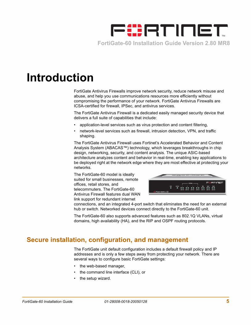
The FortiGate-60 model is ideally suited for small businesses, remote offices, retail stores, and telecommuters. The FortiGate-60 Antivirus Firewall features dual WAN link support for redundant internet connections, and an integrated 4-port switch that eliminates the need for an external hub or switch. Networked devices connect directly to the FortiGate-60 unit.
The FortiGate-60 also supports advanced features such as 802.1Q VLANs, virtual domains, high availability (HA), and the RIP and OSPF routing protocols.
Secure installation, configuration, and managementThe FortiGate unit default configuration includes a default firewall policy and IP addresses and is only a few steps away from protecting your network. There are several ways to configure basic FortiGate settings:
• the web-based manager,• the command line interface (CLI), or• the setup wizard.
INTERNAL
DMZ4321
LINK 100 LINK 100 LINK 100 LINK 100 LINK 100 LINK 100 LINK 100
WAN1 WAN2PWR STATUS
FortiGate-60 Installation Guide 01-28008-0018-20050128 5
Secure installation, configuration, and management Introduction
The CLI or the web-based manager can then be used to complete configuration and to perform maintenance and administration.
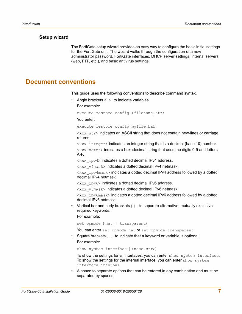
Web-based managerUsing HTTP or a secure HTTPS connection from any computer running Internet Explorer, you can configure and manage the FortiGate unit. The web-based manager supports multiple languages. You can configure the FortiGate unit for HTTP and HTTPS administration from any FortiGate interface.
You can use the web-based manager to configure most FortiGate settings. You can also use the web-based manager to monitor the status of the FortiGate unit. Configuration changes made using the web-based manager are effective immediately without resetting the firewall or interrupting service. Once you are satisfied with a configuration, you can download and save it. The saved configuration can be restored at any time.
Figure 1: FortiGate web-based manager and setup wizard
Command line interfaceYou can access the FortiGate command line interface (CLI) by connecting a management computer serial port to the FortiGate RS-232 serial console connector. You can also use Telnet or a secure SSH connection to connect to the CLI from any network that is connected to the FortiGate unit, including the Internet.
The CLI supports the same configuration and monitoring functionality as the web-based manager. In addition, you can use the CLI for advanced configuration options that are not available from the web-based manager.
This Installation Guide contains information about basic and advanced CLI commands. For a more complete description about connecting to and using the FortiGate CLI, see the FortiGate CLI Reference Guide.
6 01-28008-0018-20050128 Fortinet Inc.
Introduction Document conventions
Setup wizard
The FortiGate setup wizard provides an easy way to configure the basic initial settings for the FortiGate unit. The wizard walks through the configuration of a new administrator password, FortiGate interfaces, DHCP server settings, internal servers (web, FTP, etc.), and basic antivirus settings.
Document conventionsThis guide uses the following conventions to describe command syntax.
• Angle brackets < > to indicate variables.For example:
execute restore config <filename_str>
You enter:
execute restore config myfile.bak
<xxx_str> indicates an ASCII string that does not contain new-lines or carriage returns.<xxx_integer> indicates an integer string that is a decimal (base 10) number. <xxx_octet> indicates a hexadecimal string that uses the digits 0-9 and letters A-F.<xxx_ipv4> indicates a dotted decimal IPv4 address.<xxx_v4mask> indicates a dotted decimal IPv4 netmask.<xxx_ipv4mask> indicates a dotted decimal IPv4 address followed by a dotted decimal IPv4 netmask.<xxx_ipv6> indicates a dotted decimal IPv6 address.<xxx_v6mask> indicates a dotted decimal IPv6 netmask.<xxx_ipv6mask> indicates a dotted decimal IPv6 address followed by a dotted decimal IPv6 netmask.
• Vertical bar and curly brackets {|} to separate alternative, mutually exclusive required keywords.For example:
set opmode {nat | transparent}
You can enter set opmode nat or set opmode transparent.• Square brackets [ ] to indicate that a keyword or variable is optional.
For example:
show system interface [<name_str>]
To show the settings for all interfaces, you can enter show system interface. To show the settings for the internal interface, you can enter show system interface internal.
• A space to separate options that can be entered in any combination and must be separated by spaces.
FortiGate-60 Installation Guide 01-28008-0018-20050128 7
FortiGate documentation Introduction
For example:
set allowaccess {ping https ssh snmp http telnet}
You can enter any of the following:
set allowaccess ping
set allowaccess ping https ssh
set allowaccess https ping ssh
set allowaccess snmp
In most cases to make changes to lists that contain options separated by spaces, you need to retype the whole list including all the options you want to apply and excluding all the options you want to remove.
FortiGate documentationInformation about FortiGate products is available from the following guides:
• FortiGate QuickStart Guide
Provides basic information about connecting and installing a FortiGate unit.
• FortiGate Installation Guide
Describes how to install a FortiGate unit. Includes a hardware reference, default configuration information, installation procedures, connection procedures, and basic configuration procedures. Choose the guide for your product model number.
• FortiGate Administration Guide
Provides basic information about how to configure a FortiGate unit, including how to define FortiGate protection profiles and firewall policies; how to apply intrusion prevention, antivirus protection, web content filtering, and spam filtering; and how to configure a VPN.
• FortiGate online help
Provides a context-sensitive and searchable version of the Administration Guide in HTML format. You can access online help from the web-based manager as you work.
• FortiGate CLI Reference Guide
Describes how to use the FortiGate CLI and contains a reference to all FortiGate CLI commands.
• FortiGate Log Message Reference Guide
Describes the structure of FortiGate log messages and provides information about the log messages that are generated by FortiGate units.
• FortiGate High Availability Guide
Contains in-depth information about the FortiGate high availability feature and the FortiGate clustering protocol.
8 01-28008-0018-20050128 Fortinet Inc.
Introduction Related documentation
• FortiGate IPS GuideDescribes how to configure the FortiGate Intrusion Prevention System settings and how the FortiGate IPS deals with some common attacks.
• FortiGate VPN GuideExplains how to configure VPNs using the web-based manager.
Fortinet Knowledge CenterThe most recent Fortinet technical documentation is available from the Fortinet Knowledge Center. The knowledge center contains short how-to articles, FAQs, technical notes, product and feature guides, and much more. Visit the Fortinet Knowledge Center at http://kc.forticare.com.
Comments on Fortinet technical documentationPlease send information about any errors or omissions in this document, or any Fortinet technical documentation, to [email protected].
Related documentationAdditional information about Fortinet products is available from the following related documentation.
FortiManager documentation• FortiManager QuickStart Guide
Explains how to install the FortiManager Console, set up the FortiManager Server, and configure basic settings.
• FortiManager System Administration GuideDescribes how to use the FortiManager System to manage FortiGate devices.
• FortiManager System online helpProvides a searchable version of the Administration Guide in HTML format. You can access online help from the FortiManager Console as you work.
FortiClient documentation• FortiClient Host Security User Guide
Describes how to use FortiClient Host Security software to set up a VPN connection from your computer to remote networks, scan your computer for viruses, and restrict access to your computer and applications by setting up firewall policies.
• FortiClient Host Security online helpProvides information and procedures for using and configuring the FortiClient software.
FortiGate-60 Installation Guide 01-28008-0018-20050128 9
Customer service and technical support Introduction
FortiMail documentation
• FortiMail Administration Guide
Describes how to install, configure, and manage a FortiMail unit in gateway mode and server mode, including how to configure the unit; create profiles and policies; configure antispam and antivirus filters; create user accounts; and set up logging and reporting.
• FortiMail online help
Provides a searchable version of the Administration Guide in HTML format. You can access online help from the web-based manager as you work.
• FortiMail Web Mail Online Help
Describes how to use the FortiMail web-based email client, including how to send and receive email; how to add, import, and export addresses; and how to configure message display preferences.
FortiLog documentation
• FortiLog Administration Guide
Describes how to install and configure a FortiLog unit to collect FortiGate and FortiMail log files. It also describes how to view FortiGate and FortiMail log files, generate and view log reports, and use the FortiLog unit as a NAS server.
• FortiLog online help
Provides a searchable version of the Administration Guide in HTML format. You can access online help from the web-based manager as you work.
Customer service and technical supportFor antivirus and attack definition updates, firmware updates, updated product documentation, technical support information, and other resources, please visit the Fortinet technical support web site at http://support.fortinet.com.
You can also register FortiGate Antivirus Firewalls from http://support.fortinet.com and change your registration information at any time.
Fortinet email support is available from the following addresses:
[email protected] For customers in the United States, Canada, Mexico, Latin America and South America.
[email protected] For customers in Japan, Korea, China, Hong Kong, Singapore, Malaysia, all other Asian countries, and Australia.
[email protected] For customers in the United Kingdom, Scandinavia, Mainland Europe, Africa, and the Middle East.
10 01-28008-0018-20050128 Fortinet Inc.
Introduction Customer service and technical support
For information on Fortinet telephone support, see http://support.fortinet.com.
When requesting technical support, please provide the following information:
• Your name• Company name• Location• Email address• Telephone number• FortiGate unit serial number• FortiGate model• FortiGate FortiOS firmware version• Detailed description of the problem
FortiGate-60 Installation Guide 01-28008-0018-20050128 11

Customer service and technical support Introduction
12 01-28008-0018-20050128 Fortinet Inc.
FortiGate-60 Installation Guide Version 2.80 MR8
Getting startedThis section describes unpacking, setting up, and powering on a FortiGate Antivirus Firewall unit. This section includes:
• Package contents• Mounting• Turning the FortiGate unit power on and off• Connecting to the web-based manager• Connecting to the command line interface (CLI)• Quick installation using factory defaults• Factory default FortiGate configuration settings• Planning the FortiGate configuration• Next steps
FortiGate-60 Installation Guide 01-28008-0018-20050128 13
Package contents Getting started
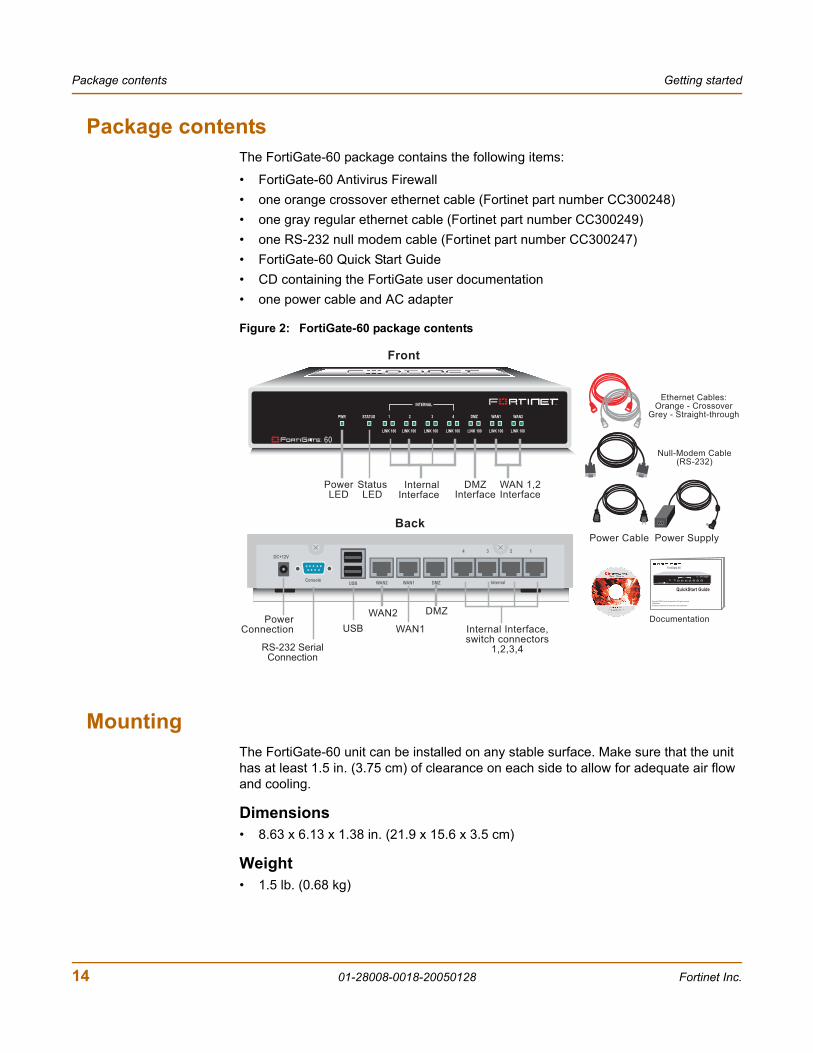
Package contentsThe FortiGate-60 package contains the following items:
• FortiGate-60 Antivirus Firewall• one orange crossover ethernet cable (Fortinet part number CC300248)• one gray regular ethernet cable (Fortinet part number CC300249)• one RS-232 null modem cable (Fortinet part number CC300247)• FortiGate-60 Quick Start Guide• CD containing the FortiGate user documentation• one power cable and AC adapter
Figure 2: FortiGate-60 package contents
MountingThe FortiGate-60 unit can be installed on any stable surface. Make sure that the unit has at least 1.5 in. (3.75 cm) of clearance on each side to allow for adequate air flow and cooling.
Dimensions• 8.63 x 6.13 x 1.38 in. (21.9 x 15.6 x 3.5 cm)
Weight• 1.5 lb. (0.68 kg)
INTERNAL
DMZ4321
LINK 100 LINK 100 LINK 100 LINK 100 LINK 100 LINK 100 LINK 100
WAN1 WAN2PWR STATUS
PowerLED
StatusLED
Internal Interface,switch connectors
1,2,3,4
WAN 1,2Interface
DMZInterface
InternalInterface
Null-Modem Cable(RS-232)
Documentation
Ethernet Cables:Orange - Crossover
Grey - Straight-through
USER MANUAL
FortiGate-60
QuickStart Guide
Copyright 2003 Fortinet Incorporated. All rights reserved.
Trademarks
Products mentioned in this document are trademarks.
Power Cable Power Supply
Back
1234
ConsoleUSB WAN2 WAN1 DMZ
DC+12V
Internal
PowerConnection
RS-232 SerialConnection
USB
WAN2 DMZ
Front
INTERNAL
DMZ4321
LINK 100 LINK 100 LINK 100 LINK 100 LINK 100 LINK 100 LINK 100
WAN1 WAN2PWR STATUS
WAN1
14 01-28008-0018-20050128 Fortinet Inc.

Getting started Turning the FortiGate unit power on and off
Power requirements• DC input voltage: 12 V• DC input current: 3 A
Environmental specifications• Operating temperature: 32 to 104°F (0 to 40°C)• Storage temperature: -13 to 158°F (-25 to 70°C)• Humidity: 5 to 95% non-condensing
Turning the FortiGate unit power on and offTo power on the FortiGate unit
1 Connect the AC adapter to the power connection at the back of the FortiGate-60 unit.
2 Connect the AC adapter to the power cable.
3 Connect the power cable to a power outlet.The FortiGate-60 unit starts. The Power and Status LEDs are on.
To power off the FortiGate unitAlways shut down the FortiGate operating system properly before turning off the power switch.
1 From the web-based manager, go to System > Maintenance > ShutDown, select Shut Down and select Apply, or from the CLI, enter:
execute shutdown
2 Disconnect the power supply.
Table 1: FortiGate-60M LED indicators
LED State DescriptionPower Green The FortiGate unit is powered on.
Off The FortiGate unit is powered off.
Status Green The FortiGate unit is starting up.
Off The FortiGate unit is running normally.
Link(Internal DMZWAN1WAN2)
Green The correct cable is in use and the connected equipment has power.
Flashing Green Network activity at this interface.
Off No link established.
100(Internal DMZWAN1WAN2)
Green The interface is connected at 100 Mbps.
FortiGate-60 Installation Guide 01-28008-0018-20050128 15

Connecting to the web-based manager Getting started
Connecting to the web-based managerUse the following procedure to connect to the web-based manager for the first time. Configuration changes made with the web-based manager are effective immediately without resetting the firewall or interrupting service.
To connect to the web-based manager, you need:
• a computer with an ethernet connection,• Internet Explorer version 6.0 or higher,• an ethernet cable.
To connect to the web-based manager1 Set the IP address of the computer with an ethernet connection to the static IP
address 192.168.1.2 with a netmask of 255.255.255.0.You can also configure the management computer to obtain an IP address automatically using DHCP. The FortiGate DHCP server assigns the management computer an IP address in the range 192.168.1.1 to 192.168.1.254.
2 Using the ethernet cable, connect the internal interface of the FortiGate unit to the computer ethernet connection.
3 Start Internet Explorer and browse to the address https://192.168.1.99. (remember to include the “s” in https://).The FortiGate login is displayed.
Figure 3: FortiGate login
4 Type admin in the Name field and select Login.
Note: You can use the web-based manager with recent versions of most popular web browsers. The web-based manager is fully supported for Internet Explorer version 6.0 or higher.
16 01-28008-0018-20050128 Fortinet Inc.

Getting started Connecting to the command line interface (CLI)
Connecting to the command line interface (CLI)As an alternative to the web-based manager, you can install and configure the FortiGate unit using the CLI. Configuration changes made with the CLI are effective immediately without resetting the firewall or interrupting service.
To connect to the FortiGate CLI, you need:
• a computer with an available communications port,• the null modem cable included in your FortiGate package,• terminal emulation software such as HyperTerminal for Windows.
To connect to the CLI1 Connect the null modem cable to the communications port of your computer and to
the FortiGate Console port.
2 Make sure that the FortiGate unit is powered on.
3 Start HyperTerminal, enter a name for the connection, and select OK.
4 Configure HyperTerminal to connect directly to the communications port on your computer and select OK.
5 Select the following port settings and select OK.
6 Press Enter to connect to the FortiGate CLI.The following prompt is displayed:FortiGate-60 login:
7 Type admin and press Enter twice.The following prompt is displayed:Welcome !
Type ? to list available commands. For information about how to use the CLI, see the FortiGate CLI Reference Guide.
Note: The following procedure describes how to connect to the CLI using Windows HyperTerminal software. You can use any terminal emulation program.
Bits per second 9600
Data bits 8
Parity None
Stop bits 1
Flow control None
FortiGate-60 Installation Guide 01-28008-0018-20050128 17
Quick installation using factory defaults Getting started
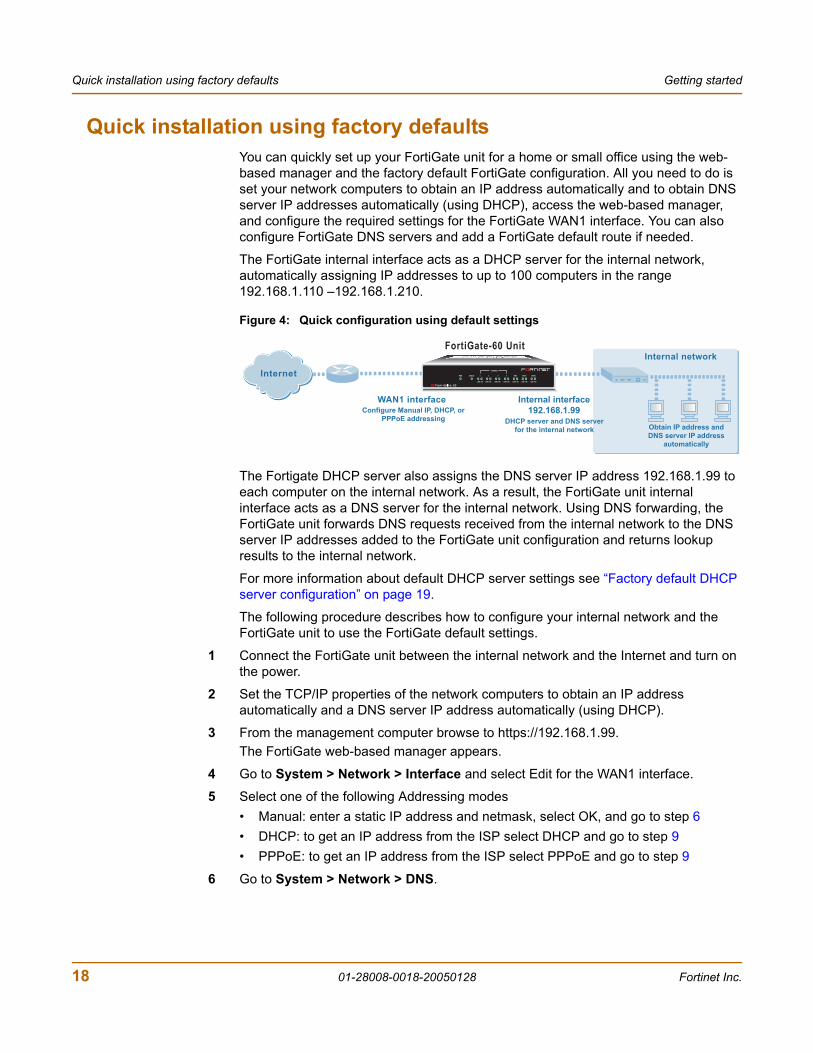
Quick installation using factory defaultsYou can quickly set up your FortiGate unit for a home or small office using the web-based manager and the factory default FortiGate configuration. All you need to do is set your network computers to obtain an IP address automatically and to obtain DNS server IP addresses automatically (using DHCP), access the web-based manager, and configure the required settings for the FortiGate WAN1 interface. You can also configure FortiGate DNS servers and add a FortiGate default route if needed.
The FortiGate internal interface acts as a DHCP server for the internal network, automatically assigning IP addresses to up to 100 computers in the range 192.168.1.110 –192.168.1.210.
Figure 4: Quick configuration using default settings
The Fortigate DHCP server also assigns the DNS server IP address 192.168.1.99 to each computer on the internal network. As a result, the FortiGate unit internal interface acts as a DNS server for the internal network. Using DNS forwarding, the FortiGate unit forwards DNS requests received from the internal network to the DNS server IP addresses added to the FortiGate unit configuration and returns lookup results to the internal network.
For more information about default DHCP server settings see “Factory default DHCP server configuration” on page 19.
The following procedure describes how to configure your internal network and the FortiGate unit to use the FortiGate default settings.
1 Connect the FortiGate unit between the internal network and the Internet and turn on the power.
2 Set the TCP/IP properties of the network computers to obtain an IP address automatically and a DNS server IP address automatically (using DHCP).
3 From the management computer browse to https://192.168.1.99.The FortiGate web-based manager appears.
4 Go to System > Network > Interface and select Edit for the WAN1 interface.
5 Select one of the following Addressing modes• Manual: enter a static IP address and netmask, select OK, and go to step 6• DHCP: to get an IP address from the ISP select DHCP and go to step 9• PPPoE: to get an IP address from the ISP select PPPoE and go to step 9
6 Go to System > Network > DNS.
FortiGate-60 Unit
Internal network
WAN1 interfaceConfigure Manual IP, DHCP, or
PPPoE addressing
Internal interface
192.168.1.99DHCP server and DNS server
for the internal network Obtain IP address and
DNS server IP address
automatically
InternetINTERNAL
DMZ4321
LINK 100 LINK 100 LINK 100 LINK 100 LINK 100 LINK 100 LINK 100
WAN1 WAN2PWR STATUS
18 01-28008-0018-20050128 Fortinet Inc.
Getting started Factory default FortiGate configuration settings
7 Select one of the following DNS settings• Obtain DNS server address automatically: select to get the DNS addresses from
the ISP, select Apply• Use the following DNS server addresses: select and enter the DNS server
addresses given to you by the ISP, select Apply
8 Go to Router > Static, edit route #1 and change Gateway to the default gateway IP address from the ISP and select OK.Network configuration is complete. Proceed to “Next steps” on page 26.
9 Select Retrieve default gateway from server and Override internal DNS options if your ISP supports them, select OK, and proceed to “Next steps” on page 26.Go to step 6 if you are not selecting these options.
Factory default FortiGate configuration settingsThe FortiGate unit is shipped with a factory default configuration. The default configuration allows you to connect to and use the FortiGate web-based manager to configure the FortiGate unit onto the network. To configure the FortiGate unit onto the network you add an administrator password, change network interface IP addresses, add DNS server IP addresses, and configure basic routing, if required.
If you plan to operate the FortiGate unit in Transparent mode, you can switch to Transparent mode from the factory default configuration and then configure the FortiGate unit onto the network in Transparent mode.
Once the network configuration is complete, you can perform additional configuration tasks such as setting system time, configuring virus and attack definition updates, and registering the FortiGate unit.
The factory default firewall configuration includes a single network address translation (NAT) policy that allows users on your internal network to connect to the external network, and stops users on the external network from connecting to the internal network. You can add more firewall policies to provide more control of the network traffic passing through the FortiGate unit.
The factory default protection profiles can be used to apply different levels of antivirus protection, web content filtering, spam filtering, and IPS to the network traffic that is controlled by firewall policies.
• Factory default DHCP server configuration• Factory default NAT/Route mode network configuration• Factory default Transparent mode network configuration• Factory default firewall configuration• Factory default protection profiles
Factory default DHCP server configurationUsing the factory default DHCP server settings you can quickly configure the internal network and the FortiGate unit. See “Quick installation using factory defaults” on page 18.
FortiGate-60 Installation Guide 01-28008-0018-20050128 19

Factory default FortiGate configuration settings Getting started
Factory default NAT/Route mode network configurationWhen the FortiGate unit is first powered on, it is running in NAT/Route mode and has the basic network configuration listed in Table 3 on page 20. This configuration allows you to connect to the FortiGate unit web-based manager and establish the configuration required to connect the FortiGate unit to the network. In Table 3 on page 20, HTTPS administrative access means you can connect to the web-based manager using HTTPS protocol through this interface. Ping administrative access means this interface responds to ping requests.
Table 2: FortiGate DHCP Server default configuration
Name internal_dhcp_server
Interface Internal
Default Gateway 192.168.1.99
IP Range 192.168.1.110 – 192.168.1.210
Network Mask 255.255.255.0
Lease Duration 7 days
DNS Server 1 192.168.1.99
Table 3: Factory default NAT/Route mode network configuration
Administrator account
User name: admin
Password: (none)
Internal interface
IP: 192.168.1.99
Netmask: 255.255.255.0
Administrative Access: HTTP, HTTPS, Ping
WAN1 interfaceIP: 192.168.100.99
Netmask: 255.255.255.0
Administrative Access: Ping
WAN2 interfaceIP: 192.168.101.99
Netmask: 255.255.255.0
Administrative Access: Ping
DMZ interfaceIP: 10.10.10.1
Netmask: 255.255.255.0
Administrative Access: HTTPS, Ping
Modem interfaceIP: 0.0.0.0
Netmask: 0.0.0.0
Administrative Access:
20 01-28008-0018-20050128 Fortinet Inc.
Getting started Factory default FortiGate configuration settings
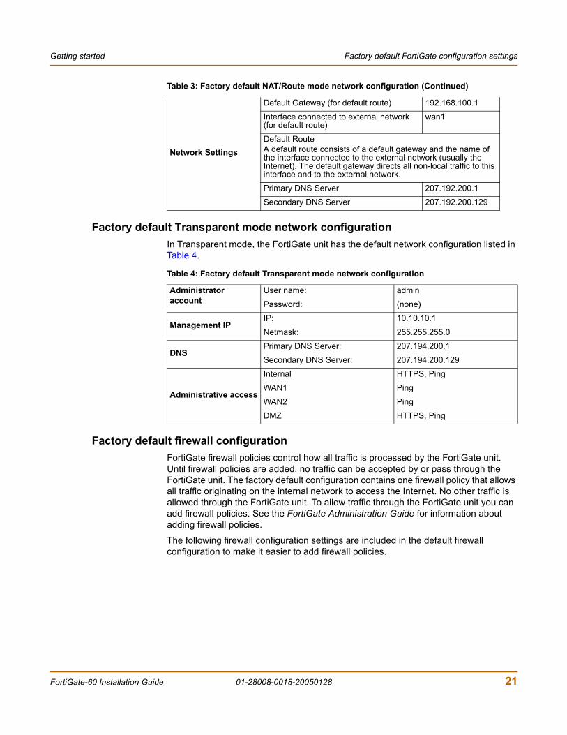
Factory default Transparent mode network configurationIn Transparent mode, the FortiGate unit has the default network configuration listed in Table 4.
Factory default firewall configurationFortiGate firewall policies control how all traffic is processed by the FortiGate unit. Until firewall policies are added, no traffic can be accepted by or pass through the FortiGate unit. The factory default configuration contains one firewall policy that allows all traffic originating on the internal network to access the Internet. No other traffic is allowed through the FortiGate unit. To allow traffic through the FortiGate unit you can add firewall policies. See the FortiGate Administration Guide for information about adding firewall policies.
The following firewall configuration settings are included in the default firewall configuration to make it easier to add firewall policies.
Network Settings
Default Gateway (for default route) 192.168.100.1
Interface connected to external network (for default route)
wan1
Default RouteA default route consists of a default gateway and the name of the interface connected to the external network (usually the Internet). The default gateway directs all non-local traffic to this interface and to the external network.
Primary DNS Server 207.192.200.1
Secondary DNS Server 207.192.200.129
Table 3: Factory default NAT/Route mode network configuration (Continued)
Table 4: Factory default Transparent mode network configuration
Administrator account
User name: admin
Password: (none)
Management IPIP: 10.10.10.1
Netmask: 255.255.255.0
DNSPrimary DNS Server: 207.194.200.1
Secondary DNS Server: 207.194.200.129
Administrative access
Internal HTTPS, Ping
WAN1 Ping
WAN2 Ping
DMZ HTTPS, Ping
FortiGate-60 Installation Guide 01-28008-0018-20050128 21
Factory default FortiGate configuration settings Getting started
The factory default firewall configuration is the same in NAT/Route and Transparent mode.
Factory default protection profilesUse protection profiles to apply different protection settings for traffic that is controlled by firewall policies. You can use protection profiles to:
• Configure antivirus protection for HTTP, FTP, IMAP, POP3, and SMTP firewall policies
• Configure Web filtering for HTTP firewall policies• Configure Web category filtering for HTTP firewall policies• Configure spam filtering for IMAP, POP3, and SMTP firewall policies• Enable the Intrusion Protection System (IPS) for all services• Enable content logging for HTTP, FTP, IMAP, POP3, and SMTP firewall policies
Using protection profiles, you can build protection configurations that can be applied to different types of firewall policies. This allows you to customize types and levels of protection for different firewall policies.
For example, while traffic between internal and external addresses might need strict protection, traffic between trusted internal addresses might need moderate protection. You can configure firewall policies for different traffic services to use the same or different protection profiles.
Protection profiles can be added to NAT/Route mode and Transparent mode firewall policies.
The FortiGate unit comes preconfigured with four protection profiles.
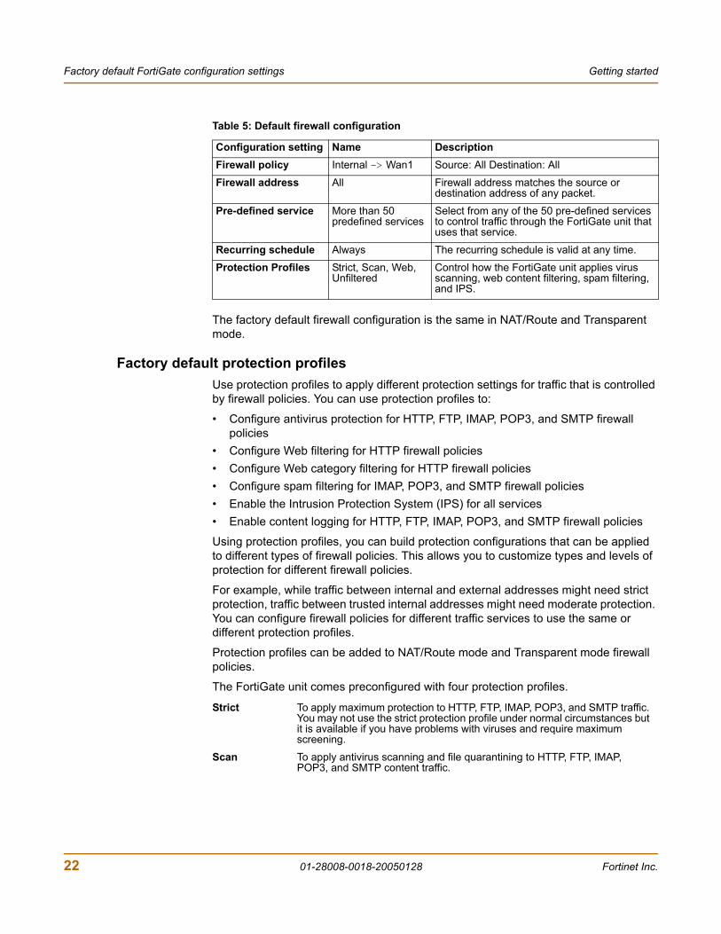
Table 5: Default firewall configuration
Configuration setting Name DescriptionFirewall policy Internal -> Wan1 Source: All Destination: All
Firewall address All Firewall address matches the source or destination address of any packet.
Pre-defined service More than 50 predefined services
Select from any of the 50 pre-defined services to control traffic through the FortiGate unit that uses that service.
Recurring schedule Always The recurring schedule is valid at any time.
Protection Profiles Strict, Scan, Web, Unfiltered
Control how the FortiGate unit applies virus scanning, web content filtering, spam filtering, and IPS.
Strict To apply maximum protection to HTTP, FTP, IMAP, POP3, and SMTP traffic. You may not use the strict protection profile under normal circumstances but it is available if you have problems with viruses and require maximum screening.
Scan To apply antivirus scanning and file quarantining to HTTP, FTP, IMAP, POP3, and SMTP content traffic.
22 01-28008-0018-20050128 Fortinet Inc.
Getting started Planning the FortiGate configuration
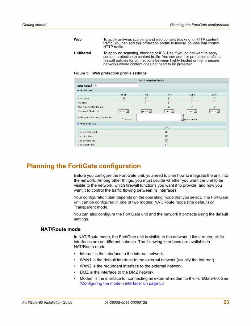
Figure 5: Web protection profile settings
Planning the FortiGate configurationBefore you configure the FortiGate unit, you need to plan how to integrate the unit into the network. Among other things, you must decide whether you want the unit to be visible to the network, which firewall functions you want it to provide, and how you want it to control the traffic flowing between its interfaces.
Your configuration plan depends on the operating mode that you select. The FortiGate unit can be configured in one of two modes: NAT/Route mode (the default) or Transparent mode.
You can also configure the FortiGate unit and the network it protects using the default settings.
NAT/Route modeIn NAT/Route mode, the FortiGate unit is visible to the network. Like a router, all its interfaces are on different subnets. The following interfaces are available in NAT/Route mode:
• Internal is the interface to the internal network. • WAN1 is the default interface to the external network (usually the Internet).• WAN2 is the redundant interface to the external network. • DMZ is the interface to the DMZ network.• Modem is the interface for connecting an external modem to the FortiGate-60. See
“Configuring the modem interface” on page 55
Web To apply antivirus scanning and web content blocking to HTTP content traffic. You can add this protection profile to firewall policies that control HTTP traffic.
Unfiltered To apply no scanning, blocking or IPS. Use if you do not want to apply content protection to content traffic. You can add this protection profile to firewall policies for connections between highly trusted or highly secure networks where content does not need to be protected.
FortiGate-60 Installation Guide 01-28008-0018-20050128 23
Planning the FortiGate configuration Getting started
You must configure routing to support the redundant WAN1 and WAN2 internet connections. Routing can be used to automatically redirect connections from an interface if its connection to the external network fails.
You can add firewall policies to control whether communications through the FortiGate unit operate in NAT or Route mode. Firewall policies control the flow of traffic based on the source address, destination address, and service of each packet. In NAT mode, the FortiGate unit performs network address translation before it sends the packet to the destination network. In Route mode, there is no address translation.
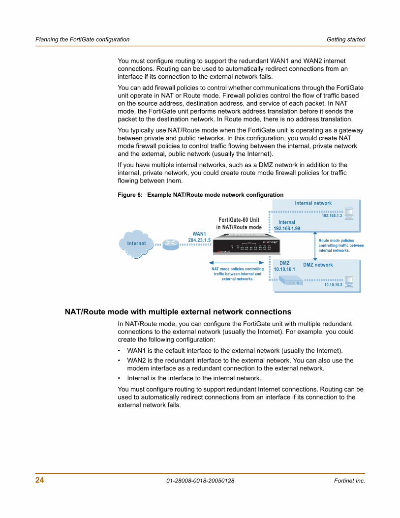
You typically use NAT/Route mode when the FortiGate unit is operating as a gateway between private and public networks. In this configuration, you would create NAT mode firewall policies to control traffic flowing between the internal, private network and the external, public network (usually the Internet).
If you have multiple internal networks, such as a DMZ network in addition to the internal, private network, you could create route mode firewall policies for traffic flowing between them.
Figure 6: Example NAT/Route mode network configuration
NAT/Route mode with multiple external network connectionsIn NAT/Route mode, you can configure the FortiGate unit with multiple redundant connections to the external network (usually the Internet). For example, you could create the following configuration:
• WAN1 is the default interface to the external network (usually the Internet). • WAN2 is the redundant interface to the external network. You can also use the
modem interface as a redundant connection to the external network.• Internal is the interface to the internal network.
You must configure routing to support redundant Internet connections. Routing can be used to automatically redirect connections from an interface if its connection to the external network fails.
FortiGate-60 Unit
in NAT/Route mode
Route mode policies
controlling traffic between
internal networks.
Internal network
DMZ network
Internal
192.168.1.99
DMZ
10.10.10.1
192.168.1.3
10.10.10.2
WAN1
204.23.1.5
NAT mode policies controlling
traffic between internal and
external networks.
Internet INTERNAL
DMZ4321
LINK 100 LINK 100 LINK 100 LINK 100 LINK 100 LINK 100 LINK 100
WAN1 WAN2PWR STATUS
24 01-28008-0018-20050128 Fortinet Inc.
Getting started Planning the FortiGate configuration
Otherwise, security policy configuration is similar to a NAT/Route mode configuration with a single Internet connection. You would create NAT mode firewall policies to control traffic flowing between the internal, private network and the external, public network (usually the Internet). If you have multiple internal networks, such as one or more DMZ networks, in addition to the internal, private network, you can create route mode firewall policies for traffic flowing between them.
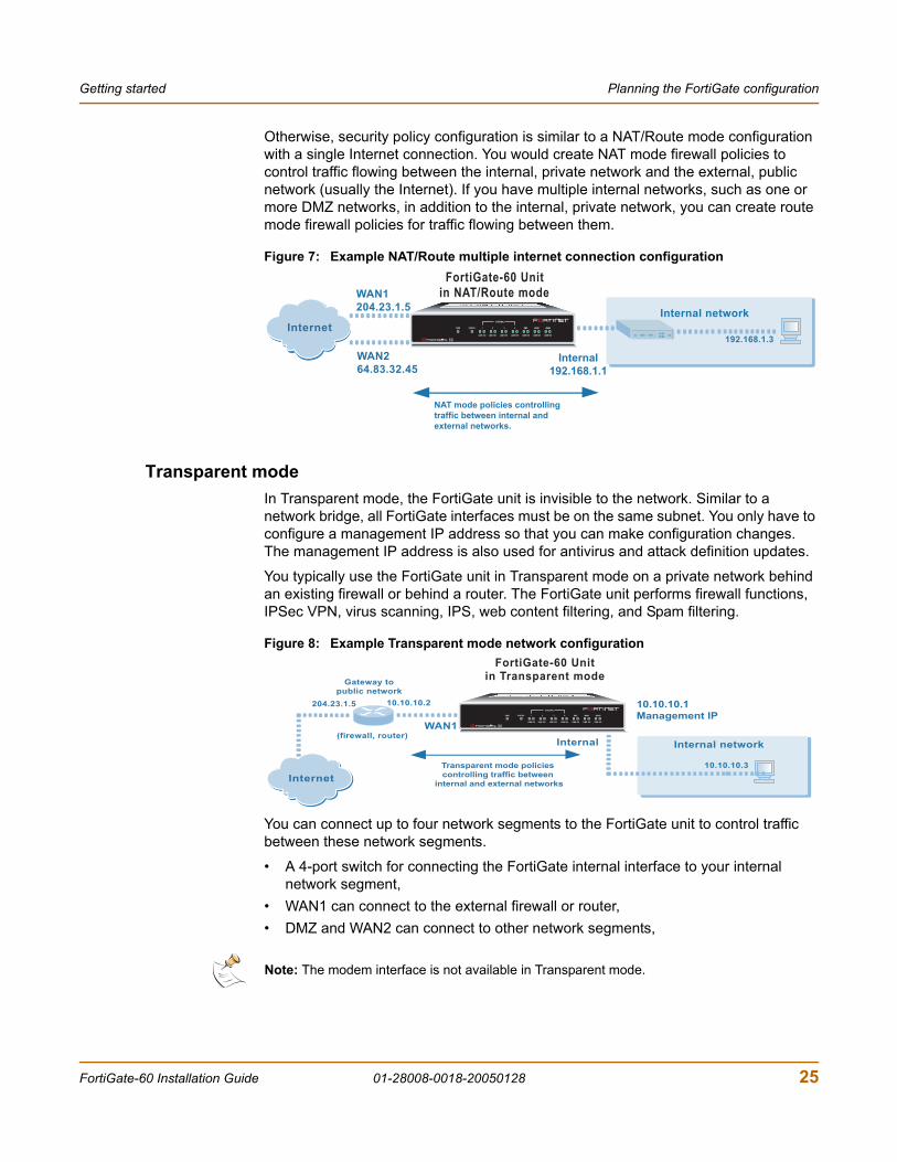
Figure 7: Example NAT/Route multiple internet connection configuration
Transparent modeIn Transparent mode, the FortiGate unit is invisible to the network. Similar to a network bridge, all FortiGate interfaces must be on the same subnet. You only have to configure a management IP address so that you can make configuration changes. The management IP address is also used for antivirus and attack definition updates.
You typically use the FortiGate unit in Transparent mode on a private network behind an existing firewall or behind a router. The FortiGate unit performs firewall functions, IPSec VPN, virus scanning, IPS, web content filtering, and Spam filtering.
Figure 8: Example Transparent mode network configuration
You can connect up to four network segments to the FortiGate unit to control traffic between these network segments.
• A 4-port switch for connecting the FortiGate internal interface to your internal network segment,
• WAN1 can connect to the external firewall or router,• DMZ and WAN2 can connect to other network segments,
FortiGate-60 Unitin NAT/Route modeWAN1
204.23.1.5
WAN264.83.32.45
NAT mode policies controllingtraffic between internal andexternal networks.
Internet
Internal192.168.1.1
Internal network
192.168.1.3
INTERNAL
DMZ4321
LINK 100 LINK 100 LINK 100 LINK 100 LINK 100 LINK 100 LINK 100
WAN1 WAN2PWR STATUS
Note: The modem interface is not available in Transparent mode.
FortiGate-60 Unit
in Transparent mode
Internet
10.10.10.1
Management IP
10.10.10.3
WAN1
Internal
10.10.10.2
Transparent mode policies
controlling traffic between
internal and external networks
204.23.1.5
(firewall, router)
Gateway to
public network
Internal network
INTERNAL
DMZ4321
LINK 100 LINK 100 LINK 100 LINK 100 LINK 100 LINK 100 LINK 100
WAN1 WAN2PWR STATUS
FortiGate-60 Installation Guide 01-28008-0018-20050128 25
Next steps Getting started
Configuration optionsOnce you have selected Transparent or NAT/Route mode operation, you can complete the configuration plan and begin to configure the FortiGate unit. Choose among three different tools to configure the FortiGate unit.
Web-based manager and setup wizardThe FortiGate web-based manager is a full featured management tool. You can use the web-based manager to configure most FortiGate settings.
The web-based manager Setup Wizard guides you through the initial configuration steps. Use the Setup Wizard to configure the administrator password, the interface addresses, the default gateway address, and the DNS server addresses. Optionally, use the Setup Wizard to configure the internal server settings for NAT/Route mode.
To connect to the web-based manager you require:
• Ethernet connection between the FortiGate unit and a management computer. • Internet Explorer version 6.0 or higher on the management computer.
CLIThe FortiGate CLI is a full-featured management tool. Use it to configure the administrator password, the interface addresses, the default gateway address, and the DNS server addresses. To connect to the CLI you require:
• Serial connection between the FortiGate unit and a management computer. • A terminal emulation application on the management computer.
If you are configuring the FortiGate unit to operate in Transparent mode, you can switch to Transparent mode from the web-based manager and then use the setup wizard to add the administration password, the management IP address and gateway, and the DNS server addresses.
Next stepsNow that your FortiGate unit is operating, you can proceed to configure it to connect to networks:
• If you are going to operate the FortiGate unit in NAT/Route mode, go to “NAT/Route mode installation” on page 27.
• If you are going to operate the FortiGate unit in Transparent mode, go to “Transparent mode installation” on page 39.
• If you are going to operate two or more FortiGate units in HA mode, go to “High availability installation” on page 47.
26 01-28008-0018-20050128 Fortinet Inc.
FortiGate-60 Installation Guide Version 2.80 MR8
NAT/Route mode installationThis chapter describes how to install the FortiGate unit in NAT/Route mode. For information about installing a FortiGate unit in Transparent mode, see “Transparent mode installation” on page 39. For information about installing two or more FortiGate units in HA mode, see “High availability installation” on page 47. For more information about installing the FortiGate unit in NAT/Route mode, see “Planning the FortiGate configuration” on page 23.
This chapter describes:
• Preparing to configure the FortiGate unit in NAT/Route mode
• Using the web-based manager
• Using the command line interface
• Using the setup wizard
• Connecting the FortiGate unit to the network(s)
• Configuring the networks
• Configuring the modem interface
• Next steps
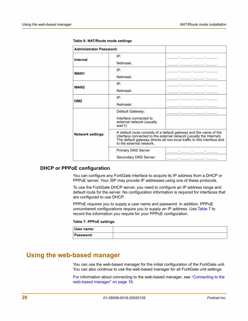
Preparing to configure the FortiGate unit in NAT/Route modeUse Table 6 on page 28 to gather the information that you need to customize NAT/Route mode settings.
You can configure the FortiGate unit in several ways:
• the web-based manager GUI is a complete interface for configuring most settings. See “Using the web-based manager” on page 28.
• the command line interface (CLI) is a complete text-based interface for configuring all settings. See “Using the command line interface” on page 30.
• the setup wizard provides easy, fast configuration of the most basic settings to get the unit up and running quickly. See “Using the setup wizard” on page 32.
The method that you choose depends on the complexity of the configuration, access and equipment, and the type of interface you are most comfortable using.
FortiGate-60 Installation Guide 01-28008-0018-20050128 27
Using the web-based manager NAT/Route mode installation
DHCP or PPPoE configurationYou can configure any FortiGate interface to acquire its IP address from a DHCP or PPPoE server. Your ISP may provide IP addresses using one of these protocols.
To use the FortiGate DHCP server, you need to configure an IP address range and default route for the server. No configuration information is required for interfaces that are configured to use DHCP.
PPPoE requires you to supply a user name and password. In addition, PPPoE unnumbered configurations require you to supply an IP address. Use Table 7 to record the information you require for your PPPoE configuration.
Using the web-based managerYou can use the web-based manager for the initial configuration of the FortiGate unit. You can also continue to use the web-based manager for all FortiGate unit settings.
For information about connecting to the web-based manager, see “Connecting to the web-based manager” on page 16.
Table 6: NAT/Route mode settings
Administrator Password:
InternalIP: _____._____._____._____
Netmask: _____._____._____._____
WAN1IP: _____._____._____._____
Netmask: _____._____._____._____
WAN2IP: _____._____._____._____
Netmask: _____._____._____._____
DMZIP: _____._____._____._____
Netmask: _____._____._____._____
Network settings
Default Gateway: _____._____._____._____
Interface connected to external network (usually wan1):
A default route consists of a default gateway and the name of the interface connected to the external network (usually the Internet). The default gateway directs all non-local traffic to this interface and to the external network.
Primary DNS Server: _____._____._____._____
Secondary DNS Server: _____._____._____._____
Table 7: PPPoE settings
User name:Password:
28 01-28008-0018-20050128 Fortinet Inc.
NAT/Route mode installation Using the web-based manager
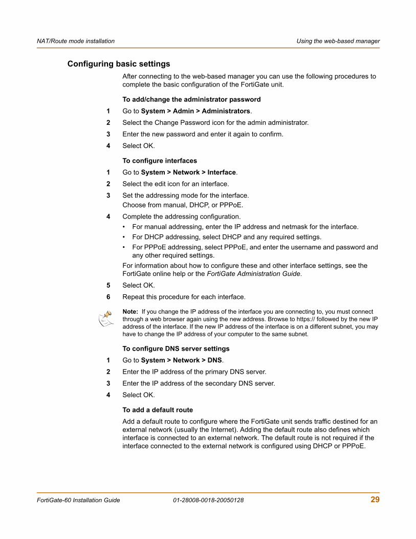
Configuring basic settingsAfter connecting to the web-based manager you can use the following procedures to complete the basic configuration of the FortiGate unit.
To add/change the administrator password1 Go to System > Admin > Administrators.
2 Select the Change Password icon for the admin administrator.
3 Enter the new password and enter it again to confirm.
4 Select OK.
To configure interfaces1 Go to System > Network > Interface.
2 Select the edit icon for an interface.
3 Set the addressing mode for the interface.Choose from manual, DHCP, or PPPoE.
4 Complete the addressing configuration.• For manual addressing, enter the IP address and netmask for the interface.• For DHCP addressing, select DHCP and any required settings.• For PPPoE addressing, select PPPoE, and enter the username and password and
any other required settings.For information about how to configure these and other interface settings, see the FortiGate online help or the FortiGate Administration Guide.
5 Select OK.
6 Repeat this procedure for each interface.
To configure DNS server settings1 Go to System > Network > DNS.
2 Enter the IP address of the primary DNS server.
3 Enter the IP address of the secondary DNS server.
4 Select OK.
To add a default routeAdd a default route to configure where the FortiGate unit sends traffic destined for an external network (usually the Internet). Adding the default route also defines which interface is connected to an external network. The default route is not required if the interface connected to the external network is configured using DHCP or PPPoE.
Note: If you change the IP address of the interface you are connecting to, you must connect through a web browser again using the new address. Browse to https:// followed by the new IP address of the interface. If the new IP address of the interface is on a different subnet, you may have to change the IP address of your computer to the same subnet.
FortiGate-60 Installation Guide 01-28008-0018-20050128 29
Using the command line interface NAT/Route mode installation
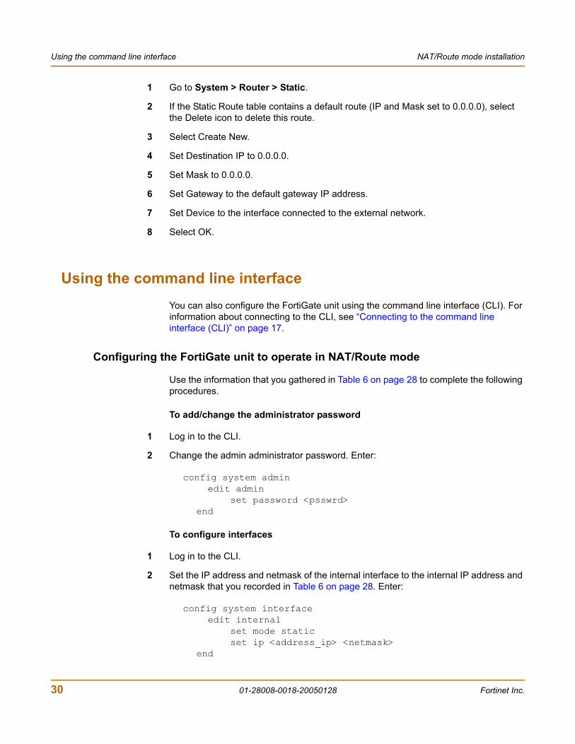
1 Go to System > Router > Static.
2 If the Static Route table contains a default route (IP and Mask set to 0.0.0.0), select the Delete icon to delete this route.
3 Select Create New.
4 Set Destination IP to 0.0.0.0.
5 Set Mask to 0.0.0.0.
6 Set Gateway to the default gateway IP address.
7 Set Device to the interface connected to the external network.
8 Select OK.
Using the command line interfaceYou can also configure the FortiGate unit using the command line interface (CLI). For information about connecting to the CLI, see “Connecting to the command line interface (CLI)” on page 17.
Configuring the FortiGate unit to operate in NAT/Route mode
Use the information that you gathered in Table 6 on page 28 to complete the following procedures.
To add/change the administrator password
1 Log in to the CLI.
2 Change the admin administrator password. Enter:
config system adminedit admin
set password <psswrd>end
To configure interfaces
1 Log in to the CLI.
2 Set the IP address and netmask of the internal interface to the internal IP address and netmask that you recorded in Table 6 on page 28. Enter:
config system interfaceedit internal
set mode staticset ip <address_ip> <netmask>
end
30 01-28008-0018-20050128 Fortinet Inc.
NAT/Route mode installation Using the command line interface
Example
config system interfaceedit internal
set mode staticset ip <192.168.120.99> <255.255.255.0>
end
3 Set the IP address and netmask of the WAN1 interface to the IP address and netmask that you recorded in Table 6 on page 28.
To set the static IP address and netmask, enter:
config system interfaceedit wan1
set mode staticset ip <address_ip> <netmask>
end
Example
config system interfaceedit wan1
set mode staticset ip 204.23.1.5 255.255.255.0
end
To set the WAN1 interface to use DHCP, enter:
config system interfaceedit wan1
set mode dhcp
end
To set the WAN1 interface to use PPPoE, enter:
config system interfaceedit wan1
set mode pppoeset connection enableset username <name_str>set password <passwrd>
end
4 Use the same syntax to set the IP address of each FortiGate interface as required.
5 Confirm that the addresses are correct. Enter:
get system interface
The CLI lists the IP address, netmask, and other settings for each of the FortiGate interfaces.
FortiGate-60 Installation Guide 01-28008-0018-20050128 31
Using the setup wizard NAT/Route mode installation
To configure DNS server settings
• Set the primary and secondary DNS server IP addresses. Enter
config system dnsset primary <address_ip>set secondary <address_ip>
end
Example
config system dnsset primary 293.44.75.21set secondary 293.44.75.22
end
To add a default route
Add a default route to configure where the FortiGate unit sends traffic that should be sent to an external network (usually the Internet). Adding the default route also defines which interface is connected to an external network. The default route is not required if the interface connected to the external network is configured using DHCP or PPPoE.
• Set the default route to the Default Gateway IP address. Enter:
config router staticedit 1
set dst 0.0.0.0 0.0.0.0set gateway <gateway_IP>set device <interface>
end
Example
If the default gateway IP is 204.23.1.2 and this gateway is connected to WAN1:
config router staticedit 1
set dst 0.0.0.0 0.0.0.0set gateway 204.23.1.2set device wan1
end
Using the setup wizardFrom the web-based manager, you can use the setup wizard to complete the initial configuration of the FortiGate unit. For information about connecting to the web-based manager, see “Connecting to the web-based manager” on page 16.
32 01-28008-0018-20050128 Fortinet Inc.
NAT/Route mode installation Using the setup wizard
If you are configuring the FortiGate unit to operate in NAT/Route mode (the default), you can use the setup wizard to:
• add the administration password• configure the internal interface address• choose either a manual (static) or a dynamic (DHCP or PPPoE) address for the
external interface• add a default route for the external interface• add the DNS server IP addresses• add the DHCP server settings and IP addresses• add various internal server IP addresses including web, IMAP, POP3, SMTP, and
FTP servers• set the antivirus protection to high, medium, or none
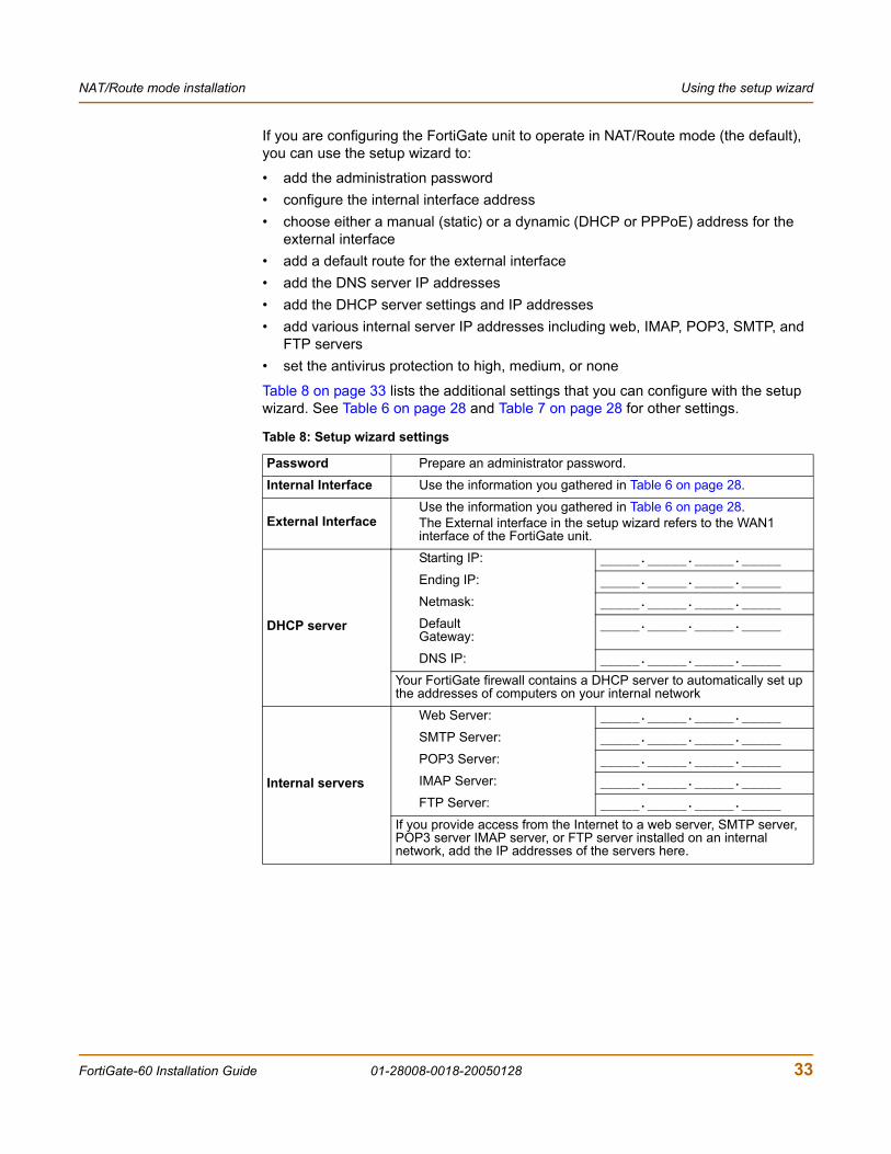
Table 8 on page 33 lists the additional settings that you can configure with the setup wizard. See Table 6 on page 28 and Table 7 on page 28 for other settings.
Table 8: Setup wizard settings
Password Prepare an administrator password.
Internal Interface Use the information you gathered in Table 6 on page 28.
External InterfaceUse the information you gathered in Table 6 on page 28.The External interface in the setup wizard refers to the WAN1 interface of the FortiGate unit.
DHCP server
Starting IP: _____._____._____._____
Ending IP: _____._____._____._____
Netmask: _____._____._____._____
Default Gateway:
_____._____._____._____
DNS IP: _____._____._____._____
Your FortiGate firewall contains a DHCP server to automatically set up the addresses of computers on your internal network
Internal servers
Web Server: _____._____._____._____
SMTP Server: _____._____._____._____
POP3 Server: _____._____._____._____
IMAP Server: _____._____._____._____
FTP Server: _____._____._____._____
If you provide access from the Internet to a web server, SMTP server, POP3 server IMAP server, or FTP server installed on an internal network, add the IP addresses of the servers here.
FortiGate-60 Installation Guide 01-28008-0018-20050128 33
Connecting the FortiGate unit to the network(s) NAT/Route mode installation
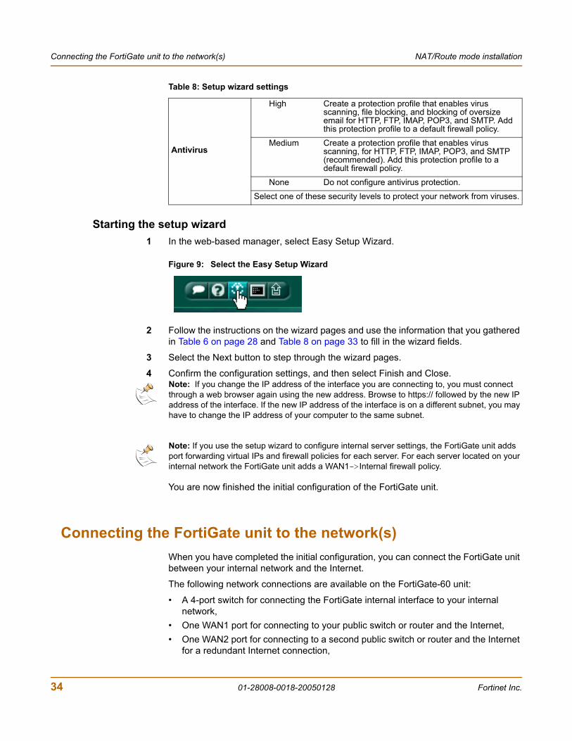
Starting the setup wizard1 In the web-based manager, select Easy Setup Wizard.
Figure 9: Select the Easy Setup Wizard
2 Follow the instructions on the wizard pages and use the information that you gathered in Table 6 on page 28 and Table 8 on page 33 to fill in the wizard fields.
3 Select the Next button to step through the wizard pages.
4 Confirm the configuration settings, and then select Finish and Close.
You are now finished the initial configuration of the FortiGate unit.
Connecting the FortiGate unit to the network(s)When you have completed the initial configuration, you can connect the FortiGate unit between your internal network and the Internet.
The following network connections are available on the FortiGate-60 unit:
• A 4-port switch for connecting the FortiGate internal interface to your internal network,
• One WAN1 port for connecting to your public switch or router and the Internet,• One WAN2 port for connecting to a second public switch or router and the Internet
for a redundant Internet connection,
Antivirus
High Create a protection profile that enables virus scanning, file blocking, and blocking of oversize email for HTTP, FTP, IMAP, POP3, and SMTP. Add this protection profile to a default firewall policy.
Medium Create a protection profile that enables virus scanning, for HTTP, FTP, IMAP, POP3, and SMTP (recommended). Add this protection profile to a default firewall policy.
None Do not configure antivirus protection.
Select one of these security levels to protect your network from viruses.
Table 8: Setup wizard settings
Note: If you change the IP address of the interface you are connecting to, you must connect through a web browser again using the new address. Browse to https:// followed by the new IP address of the interface. If the new IP address of the interface is on a different subnet, you may have to change the IP address of your computer to the same subnet.
Note: If you use the setup wizard to configure internal server settings, the FortiGate unit adds port forwarding virtual IPs and firewall policies for each server. For each server located on your internal network the FortiGate unit adds a WAN1->Internal firewall policy.
34 01-28008-0018-20050128 Fortinet Inc.
NAT/Route mode installation Connecting the FortiGate unit to the network(s)
• One DMZ port for connecting to a DMZ network.• Modem is the interface for connecting an external modem to the FortiGate-60. See
“Configuring the Modem interface” on page 36
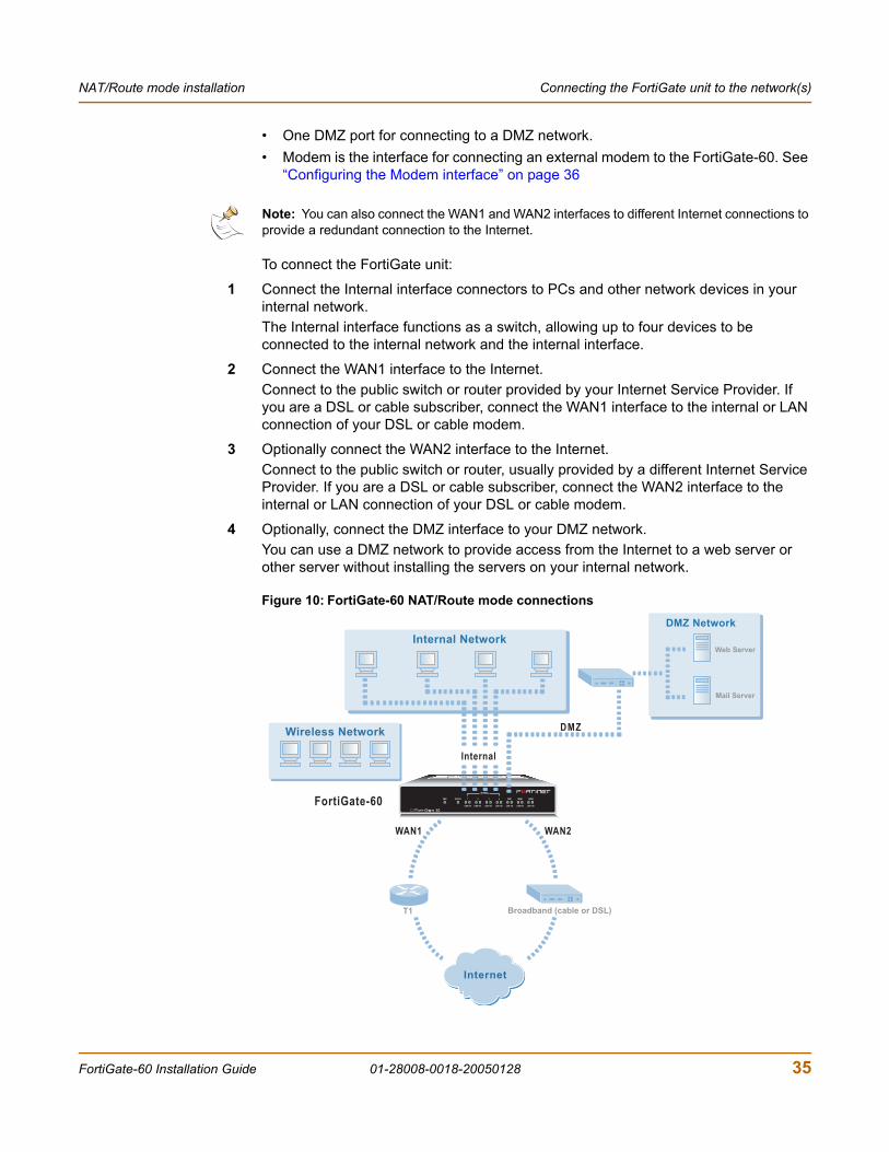
To connect the FortiGate unit:
1 Connect the Internal interface connectors to PCs and other network devices in your internal network.The Internal interface functions as a switch, allowing up to four devices to be connected to the internal network and the internal interface.
2 Connect the WAN1 interface to the Internet.Connect to the public switch or router provided by your Internet Service Provider. If you are a DSL or cable subscriber, connect the WAN1 interface to the internal or LAN connection of your DSL or cable modem.
3 Optionally connect the WAN2 interface to the Internet.Connect to the public switch or router, usually provided by a different Internet Service Provider. If you are a DSL or cable subscriber, connect the WAN2 interface to the internal or LAN connection of your DSL or cable modem.
4 Optionally, connect the DMZ interface to your DMZ network.You can use a DMZ network to provide access from the Internet to a web server or other server without installing the servers on your internal network.
Figure 10: FortiGate-60 NAT/Route mode connections
Note: You can also connect the WAN1 and WAN2 interfaces to different Internet connections to provide a redundant connection to the Internet.
INTERNAL
DMZ4321
LINK 100 LINK 100 LINK 100 LINK 100 LINK 100 LINK 100 LINK 100
WAN1 WAN2PWR STATUS
FortiGate-60
DMZ
DMZ Network
Mail Server
Web Server
Internal Network
WAN2WAN1
Internet
Broadband (cable or DSL)T1
Wireless Network
Internal
FortiGate-60 Installation Guide 01-28008-0018-20050128 35
Configuring the networks NAT/Route mode installation
Configuring the networksIf you are running the FortiGate unit in NAT/Route mode, your networks must be configured to route all Internet traffic to the IP address of the FortiGate interface to which they are connected.
• For the internal network, change the default gateway address of all computers and routers connected directly to your internal network to the IP address of the FortiGate internal interface.
• For the DMZ network, change the default gateway address of all computers and routers connected directly to your DMZ network to the IP address of the FortiGate DMZ interface.
• For the external network, route all packets to the FortiGate WAN1 or WAN 2 interface.
If you are using the FortiGate unit as the DHCP server for your internal network, configure the computers on your internal network for DHCP.
Make sure that the connected FortiGate unit is functioning properly by connecting to the Internet from a computer on the internal network. You should be able to connect to any Internet address.
Configuring the Modem interfaceIn NAT/Route mode, you use the modem interface as either a redundant interface or standalone interface to the Internet.
• In redundant mode, the modem interface automatically takes over from a selected ethernet interface when that ethernet interface is unavailable.
• In standalone mode, the modem interface is the connection from the FortiGate unit to the Internet.
When connecting to the ISP, in either configuration, the FortiGate unit modem can automatically dial up to three dialup accounts until the modem connects to an ISP.
The modem interface connects to the FortiGate USB interface. You must connect an external modem to the USB interface.
Next stepsYou can use the following information to configure FortiGate system time, to register the FortiGate unit, and to configure antivirus and attack definition updates.
Refer to the FortiGate Administration Guide for complete information on configuring, monitoring, and maintaining the FortiGate unit.
36 01-28008-0018-20050128 Fortinet Inc.
NAT/Route mode installation Next steps
To set the date and timeFor effective scheduling and logging, the FortiGate system date and time must be accurate. You can either manually set the system date and time or configure the FortiGate unit to automatically keep its time correct by synchronizing with a Network Time Protocol (NTP) server.
1 Go to System > Config > Time.
2 Select Refresh to display the current FortiGate system date and time.
3 Select a Time Zone from the list.
4 Optionally, select Automatically adjust clock for daylight saving changes check box.
5 Select Set Time and set the FortiGate system date and time.
6 Set the hour, minute, second, month, day, and year as required.
7 Select Apply.
To use NTP to set the FortiGate date and time1 Go to System > Config > Time.
2 Select Synchronize with NTP Server to configure the FortiGate unit to use NTP to automatically set the system time and date.
3 Enter the IP address or domain name of the NTP server that the FortiGate unit can use to set its time and date.
4 Specify how often the FortiGate unit should synchronize its time with the NTP server.
5 Select Apply.
To register the FortiGate unitAfter purchasing and installing a new FortiGate unit, you can register the unit by going to the System Update Support page, or using a web browser to connect to http://support.fortinet.com and selecting Product Registration.
To register, enter your contact information and the serial numbers of the FortiGate units that you or your organization have purchased. You can register multiple FortiGate units in a single session without re-entering your contact information.
To configure virus, attack, and spam definition updatesYou can configure the FortiGate unit to automatically keep virus, grayware, and attack definitions up to date.
FortiGate-60 Installation Guide 01-28008-0018-20050128 37
Next steps NAT/Route mode installation
1 Go to System > Maintenance > Update Center.2 Select Refresh to test the FortiGate unit connectivity with the FortiProtect Distribution
Network (FDN).To be able to connect to the FDN the FortiGate unit default route must point to a network such as the Internet to which a connection to the FDN can be established.If FortiProtect Distribution Network changes to Available, then the FortiGate unit can connect to the FDN.
3 Select Scheduled Update and configure a schedule for receiving antivirus and attack definition updates.
4 Select Apply.
5 You can also select Update Now to receive the latest virus and attack definition updates.
For more information about FortiGate settings see the FortiGate Online Help or the FortiGate Administration Guide.
38 01-28008-0018-20050128 Fortinet Inc.
FortiGate-60 Installation Guide Version 2.80 MR8
Transparent mode installationThis chapter describes how to install a FortiGate unit in Transparent mode. If you want to install the FortiGate unit in NAT/Route mode, see “NAT/Route mode installation” on page 27. If you want to install two or more FortiGate units in HA mode, see “High availability installation” on page 47. For more information about installing the FortiGate unit in Transparent mode, see “Planning the FortiGate configuration” on page 23.
This chapter describes:
• Preparing to configure Transparent mode• Using the web-based manager• Using the command line interface• Using the setup wizard• Connecting the FortiGate unit to your network• Next steps
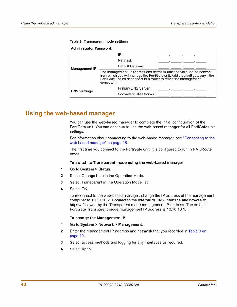
Preparing to configure Transparent modeUse Table 9 to gather the information that you need to customize Transparent mode settings.
You can configure Transparent mode using four methods:
• the web-based manager GUI• front control buttons and LCD• command line interface (CLI)• setup wizard
The method you choose depends on the complexity of the configuration, access and equipment, and the type of interface you are most comfortable using.
FortiGate-60 Installation Guide 01-28008-0018-20050128 39
Using the web-based manager Transparent mode installation
Using the web-based managerYou can use the web-based manager to complete the initial configuration of the FortiGate unit. You can continue to use the web-based manager for all FortiGate unit settings.
For information about connecting to the web-based manager, see “Connecting to the web-based manager” on page 16.
The first time you connect to the FortiGate unit, it is configured to run in NAT/Route mode.
To switch to Transparent mode using the web-based manager1 Go to System > Status.
2 Select Change beside the Operation Mode.
3 Select Transparent in the Operation Mode list.
4 Select OK.
To reconnect to the web-based manager, change the IP address of the management computer to 10.10.10.2. Connect to the internal or DMZ interface and browse to https:// followed by the Transparent mode management IP address. The default FortiGate Transparent mode management IP address is 10.10.10.1.
To change the Management IP1 Go to System > Network > Management.2 Enter the management IP address and netmask that you recorded in Table 9 on
page 40.
3 Select access methods and logging for any interfaces as required.
4 Select Apply.
Table 9: Transparent mode settings
Administrator Password:
Management IP
IP: _____._____._____._____
Netmask: _____._____._____._____
Default Gateway: _____._____._____._____
The management IP address and netmask must be valid for the network from which you will manage the FortiGate unit. Add a default gateway if the FortiGate unit must connect to a router to reach the management computer.
DNS SettingsPrimary DNS Server: _____._____._____._____
Secondary DNS Server: _____._____._____._____
40 01-28008-0018-20050128 Fortinet Inc.
Transparent mode installation Using the command line interface
To configure DNS server settings
1 Go to System > Network > DNS.
2 Enter the IP address of the primary DNS server.
3 Enter the IP address of the secondary DNS server.
4 Select OK.
To configure the default gateway
1 Go to System > Network > Management.2 Set Default Gateway to the default gateway IP address that you recorded in Table 9
on page 40.
3 Select Apply.
Reconnecting to the web-based managerIf you changed the IP address of the management interface while you were using the setup wizard, you must reconnect to the web-based manager using the new IP address. Browse to https:// followed by the new IP address of the management interface. Otherwise, you can reconnect to the web-based manager by browsing to https://10.10.10.1. If you connect to the management interface through a router, make sure that you have added a default gateway for that router to the management IP default gateway field.
Using the command line interfaceAs an alternative to the web-based manager or setup wizard you can begin the initial configuration of the FortiGate unit using the command line interface (CLI). To connect to the CLI, see “Connecting to the command line interface (CLI)” on page 17. Use the information that you gathered in Table 9 on page 40 to complete the following procedures.
To change to Transparent mode using the CLI
1 Make sure that you are logged into the CLI.
2 Switch to Transparent mode. Enter:
config system globalset opmode transparent
end
The FortiGate unit restarts. After a few seconds, the login prompt appears.
3 Type admin and press Enter.The following prompt appears:
Welcome !
4 Confirm that the FortiGate unit has switched to Transparent mode. Enter:
get system status
FortiGate-60 Installation Guide 01-28008-0018-20050128 41
Using the command line interface Transparent mode installation
The CLI displays the status of the FortiGate unit including the following line of text:
Operation mode: Transparent
To configure the management IP address
1 Make sure that you are logged into the CLI.
2 Set the management IP address and netmask to the IP address and netmask that you recorded in Table 9 on page 40. Enter:
config system manageipset ip <address_ip> <netmask>
end
Example
config system manageip set ip 10.10.10.2 255.255.255.0
end
3 Confirm that the address is correct. Enter:
get system manageip
The CLI lists the management IP address and netmask.
To configure DNS server settings
1 Set the primary and secondary DNS server IP addresses. Enter
config system dnsset primary <address_ip>set secondary <address_ip>
end
Example
config system dnsset primary 293.44.75.21set secondary 293.44.75.22
end
To configure the default gateway
1 Make sure that you are logged into the CLI.
2 Set the default route to the default gateway that you recorded in Table 9 on page 40. Enter:
config router staticedit 1
set dst 0.0.0.0 0.0.0.0set gateway <address_gateway>set device <interface>
end
42 01-28008-0018-20050128 Fortinet Inc.
Transparent mode installation Using the setup wizard
ExampleIf the default gateway IP is 204.23.1.2 and this gateway is connected to port 2:
config router staticedit 1
set dst 0.0.0.0 0.0.0.0set gateway 204.23.1.2set device port2
end
Using the setup wizardFrom the web-based manager, you can use the setup wizard to begin the initial configuration of the FortiGate unit. For information about connecting to the web-based manager, see “Connecting to the web-based manager” on page 16.
The first time you connect to the FortiGate unit, it is configured to run in NAT/Route mode.
To switch to Transparent mode using the web-based manager1 Go to System > Status.
2 Select Change beside the Operation Mode.
3 Select Transparent in the Operation Mode list.
4 Select OK.
To reconnect to the web-based manager, change the IP address of the management computer to 10.10.10.2. Connect to the internal or DMZ interface and browse to https:// followed by the Transparent mode management IP address. The default FortiGate Transparent mode management IP address is 10.10.10.1.
To start the setup wizard1 Select Easy Setup Wizard (the middle button in the upper-right corner of the
web-based manager).
2 Use the information that you gathered in Table 9 on page 40 to fill in the wizard fields. Select the Next button to step through the wizard pages.
3 Confirm your configuration settings, and then select Finish and Close.
Reconnecting to the web-based managerIf you changed the IP address of the management interface while you were using the setup wizard, you must reconnect to the web-based manager using the new IP address. Browse to https:// followed by the new IP address of the management interface. Otherwise, you can reconnect to the web-based manager by browsing to https://10.10.10.1. If you connect to the management interface through a router, make sure that you have added a default gateway for that router to the management IP default gateway field.
FortiGate-60 Installation Guide 01-28008-0018-20050128 43

Connecting the FortiGate unit to your network Transparent mode installation
Connecting the FortiGate unit to your networkWhen you have completed the initial configuration, you can connect the FortiGate unit between your internal network and the Internet using the Internal and WAN1 interfaces. You can also connect networks to the DMZ interface and the WAN2 interface.
There are seven 10/100Base-TX connectors on the FortiGate-60:
• Four Internal ports for connecting to your internal network,• WAN1 can connect to an external firewall or router. • DMZ and WAN2 can connect to other network segments.
To connect the FortiGate unit running in Transparent mode:
1 Connect the Internal interface connectors to PCs and other network devices in your internal network.The Internal interface functions as a switch, allowing up to four devices to be connected to the internal network and the internal interface.
2 Connect the WAN1 interface to the network segment connected to the external firewall or router.Connect to the public switch or router provided by your Internet Service Provider. If you are a DSL or cable subscriber, connect the WAN1 interface to the internal or LAN connection of your DSL or cable modem.
3 Optionally connect the WAN2 and DMZ interfaces to other networks.
Figure 11: FortiGate-60 Transparent mode connections
INTERNAL
DMZ4321
LINK 100 LINK 100 LINK 100 LINK 100 LINK 100 LINK 100 LINK 100
WAN1 WAN2PWR STATUS
Internet
Internal
WAN1
DMZ
FortiGate-60
Internal Network Other Network
Hub or Switch
Hub or Switch
Public Switchor Router
44 01-28008-0018-20050128 Fortinet Inc.
Transparent mode installation Next steps
Next stepsYou can use the following information to configure FortiGate system time, to register the FortiGate unit, and to configure antivirus and attack definition updates.
Refer to the FortiGate Administration Guide for complete information on configuring, monitoring, and maintaining your FortiGate unit.
To set the date and timeFor effective scheduling and logging, the FortiGate system date and time must be accurate. You can either manually set the system date and time or configure the FortiGate unit to automatically keep its time correct by synchronizing with a Network Time Protocol (NTP) server.
1 Go to System > Config > Time.
2 Select Refresh to display the current FortiGate system date and time.
3 Select your Time Zone from the list.
4 Optionally, select Automatically adjust clock for daylight saving changes check box.
5 Select Set Time and set the FortiGate system date and time.
6 Set the hour, minute, second, month, day, and year as required.
7 Select Apply.
To use NTP to set the FortiGate date and time1 Go to System > Config > Time.
2 Select Synchronize with NTP Server to configure the FortiGate unit to use NTP to automatically set the system time and date.
3 Enter the IP address or domain name of the NTP server that the FortiGate unit can use to set its time and date.
4 Specify how often the FortiGate unit should synchronize its time with the NTP server.
5 Select Apply.
To register your FortiGate unitAfter purchasing and installing a new FortiGate unit, you can register the unit by going to the System Update Support page, or using a web browser to connect to http://support.fortinet.com and selecting Product Registration.
To register, enter your contact information and the serial numbers of the FortiGate units that you or your organization have purchased. You can register multiple FortiGate units in a single session without re-entering your contact information.
To configure virus, attack, and spam definition updatesYou can configure the FortiGate unit to automatically keep virus, grayware, and attack definitions up to date.
FortiGate-60 Installation Guide 01-28008-0018-20050128 45
Next steps Transparent mode installation
1 Go to System > Maintenance > Update Center.2 Select Refresh to test the FortiGate unit connectivity with the FortiProtect Distribution
Network (FDN).To be able to connect to the FDN the FortiGate unit default route must point to a network such as the Internet to which a connection to the FDN can be established.If FortiProtect Distribution Network changes to Available, then the FortiGate unit can connect to the FDN.
3 Select Scheduled Update and configure a schedule for receiving antivirus and attack definition updates.
4 Select Apply.
5 You can also select Update Now to receive the latest virus and attack definition updates.
46 01-28008-0018-20050128 Fortinet Inc.
FortiGate-60 Installation Guide Version 2.80 MR8
High availability installationThis chapter describes how to install two or more FortiGate units in an HA cluster. HA installation involves three basic steps:
• Configuring FortiGate units for HA operation• Connecting the cluster to your networks• Installing and configuring the cluster
For information about HA, see the FortiGate Administration Guide and the FortiOS High Availability technical note.
Priorities of heartbeat device and monitor prioritiesThe procedures in this chapter do not include steps for changing the priorities of heartbeat devices or for configuring monitor priorities settings. Both of these HA settings should be configured after the cluster is up and running.
Configuring FortiGate units for HA operationA FortiGate HA cluster consists of two or more FortiGate units with the same HA configuration. This section describes how to configure each of the FortiGate units to be added to a cluster for HA operation. The procedures are the same for active-active and active-passive HA.
• High availability configuration settings• Configuring FortiGate units for HA using the web-based manager• Configuring FortiGate units for HA using the CLI
High availability configuration settingsUse the following table to select the HA configuration settings for the FortiGate units in the HA cluster.
FortiGate-60 Installation Guide 01-28008-0018-20050128 47

Configuring FortiGate units for HA operation High availability installation
Table 10: High availability settings
Mode
Active-Active Load balancing and failover HA. Each FortiGate unit in the HA cluster actively processes connections and monitors the status of the other FortiGate units in the cluster. The primary FortiGate unit in the cluster controls load balancing.
Active-Passive Failover HA. The primary FortiGate unit in the cluster processes all connections. All other FortiGate units in the cluster are passively monitor the cluster status and remain synchronized with the primary FortiGate unit.
All members of the HA cluster must be set to the same HA mode.
Group ID
The group ID range is from 0 to 63. All members of the HA cluster must have the same group ID. When the FortiGate units in the cluster are switched to HA mode, all of the interfaces of all of the units in the cluster get the same virtual MAC address. This virtual MAC address is set according to the group ID.
Group ID MAC Address0 00-09-0f-06-ff-00
1 00-09-0f-06-ff-01
2 00-09-0f-06-ff-02
3 00-09-0f-06-ff-03
…
63 00-09-0f-06-ff-3f
If you have more than one HA cluster on the same network, each cluster should have a different group ID. If two clusters on the same network have same group ID, the duplicate MAC addresses cause addressing conflicts on the network.
Unit priority
The unit with the highest priority becomes the primary unit in the cluster. The unit priority range is 0 to 255. The default unit priority is 128.Set the unit priority to a higher value if you want the FortiGate unit to be the primary cluster unit. Set the unit priority to a lower value if you want the FortiGate unit to be a subordinate unit in the cluster. If all units have the same priority, the FortiGate unit with the highest serial number becomes the primary cluster unit.
Override Master
You can configure a FortiGate unit to always become the primary unit in the cluster by giving it a high priority and by selecting Override master.
48 01-28008-0018-20050128 Fortinet Inc.
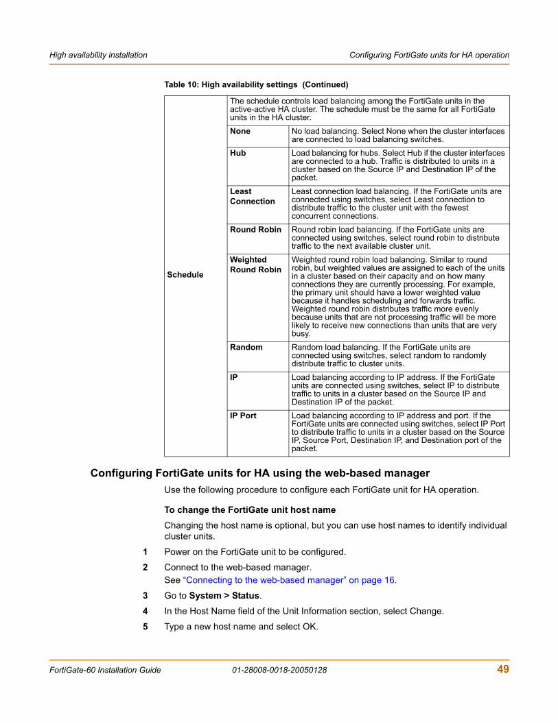
High availability installation Configuring FortiGate units for HA operation
Configuring FortiGate units for HA using the web-based managerUse the following procedure to configure each FortiGate unit for HA operation.
To change the FortiGate unit host nameChanging the host name is optional, but you can use host names to identify individual cluster units.
1 Power on the FortiGate unit to be configured.
2 Connect to the web-based manager.See “Connecting to the web-based manager” on page 16.
3 Go to System > Status.
4 In the Host Name field of the Unit Information section, select Change.
5 Type a new host name and select OK.
Schedule
The schedule controls load balancing among the FortiGate units in the active-active HA cluster. The schedule must be the same for all FortiGate units in the HA cluster.
None No load balancing. Select None when the cluster interfaces are connected to load balancing switches.
Hub Load balancing for hubs. Select Hub if the cluster interfaces are connected to a hub. Traffic is distributed to units in a cluster based on the Source IP and Destination IP of the packet.
Least Connection
Least connection load balancing. If the FortiGate units are connected using switches, select Least connection to distribute traffic to the cluster unit with the fewest concurrent connections.
Round Robin Round robin load balancing. If the FortiGate units are connected using switches, select round robin to distribute traffic to the next available cluster unit.
Weighted Round Robin
Weighted round robin load balancing. Similar to round robin, but weighted values are assigned to each of the units in a cluster based on their capacity and on how many connections they are currently processing. For example, the primary unit should have a lower weighted value because it handles scheduling and forwards traffic. Weighted round robin distributes traffic more evenly because units that are not processing traffic will be more likely to receive new connections than units that are very busy.
Random Random load balancing. If the FortiGate units are connected using switches, select random to randomly distribute traffic to cluster units.
IP Load balancing according to IP address. If the FortiGate units are connected using switches, select IP to distribute traffic to units in a cluster based on the Source IP and Destination IP of the packet.
IP Port Load balancing according to IP address and port. If the FortiGate units are connected using switches, select IP Port to distribute traffic to units in a cluster based on the Source IP, Source Port, Destination IP, and Destination port of the packet.
Table 10: High availability settings (Continued)
FortiGate-60 Installation Guide 01-28008-0018-20050128 49

Configuring FortiGate units for HA operation High availability installation
To configure a FortiGate unit for HA operation1 Go to System > Config > HA.
2 Select High Availability.
3 Select the mode.
4 Select a Group ID for the HA cluster.
5 If required, change the Unit Priority.
6 If required, select Override master.
7 Enter and confirm a password for the HA cluster.
8 If you are configuring Active-Active HA, select a schedule.
9 Select Apply.The FortiGate unit negotiates to establish an HA cluster. When you select apply you may temporarily lose connectivity with the FortiGate unit as the negotiation takes place.
10 If you are configuring a NAT/Route mode cluster, power off the FortiGate unit and then repeat this procedure for all the FortiGate units in the cluster. Once all of the units are configured, continue with “Connecting the cluster to your networks” on page 51.
11 If you are configuring a Transparent mode cluster, reconnect to the web-based manager.You may have to wait a few minutes before you can reconnect.
12 Go to System > Status.
13 Select Change to Transparent Mode and select OK to switch the FortiGate unit to Transparent mode.
14 Allow the FortiGate unit to restart in Transparent mode and then power off the FortiGate unit.
15 Repeat this procedure for all of the FortiGate units in the cluster.
16 Once all units are configured, continue with “Connecting the cluster to your networks” on page 51.
Configuring FortiGate units for HA using the CLIUse the following procedure to configure each FortiGate unit for HA operation.
To change the FortiGate unit host name1 Power on the FortiGate unit to be configured.
2 Connect to the CLI.See “Connecting to the command line interface (CLI)” on page 17.
3 Change the host name.
config system globalset hostname <name_str>
end
50 01-28008-0018-20050128 Fortinet Inc.
High availability installation Connecting the cluster to your networks
To configure the FortiGate unit for HA operation1 Configure HA settings.
Use the following command to:• Set the HA mode• Set the Group ID• Change the unit priority• Enable override master• Enter an HA password• Select an active-active HA schedule
config system haset mode {a-a | a-p | standalone}set groupid <id_integer>set priority <priority_integer>set override {disable | enable}set password <password_str>set schedule {hub | ip | ipport | leastconnection | none
| random | round-robin | weight-round-robin}end
The FortiGate unit negotiates to establish an HA cluster.
2 If you are configuring a NAT/Route mode cluster, power off the FortiGate unit and then repeat this procedure for all the FortiGate units in the cluster. Once all of the units are configured, continue with “Connecting the cluster to your networks” on page 51.
3 If you are configuring a Transparent mode cluster, switch the FortiGate unit to Transparent mode.
config system globalset opmode transparent
end
4 Allow the FortiGate unit to restart in Transparent mode and then power off the FortiGate unit.
5 Repeat this procedure for all of the FortiGate units in the cluster then continue with “Connecting the cluster to your networks” on page 51.
Connecting the cluster to your networksUse the following procedure to connect a cluster operating in NAT/Route mode or Transparent mode. Connect the FortiGate units in the cluster to each other and to your network. You must connect all matching interfaces in the cluster to the same hub or switch. Then you must connect these interfaces to their networks using the same hub or switch.
Fortinet recommends using switches for all cluster connections for the best performance.
FortiGate-60 Installation Guide 01-28008-0018-20050128 51
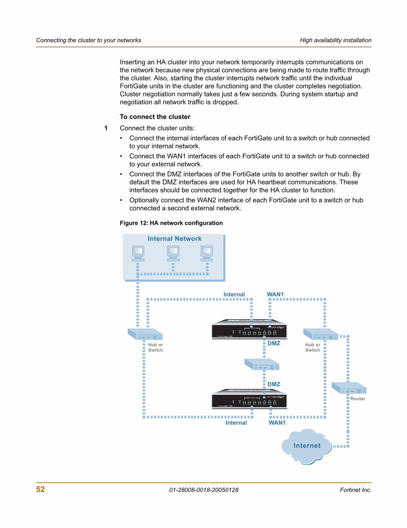
Connecting the cluster to your networks High availability installation
Inserting an HA cluster into your network temporarily interrupts communications on the network because new physical connections are being made to route traffic through the cluster. Also, starting the cluster interrupts network traffic until the individual FortiGate units in the cluster are functioning and the cluster completes negotiation. Cluster negotiation normally takes just a few seconds. During system startup and negotiation all network traffic is dropped.
To connect the cluster1 Connect the cluster units:
• Connect the internal interfaces of each FortiGate unit to a switch or hub connected to your internal network.
• Connect the WAN1 interfaces of each FortiGate unit to a switch or hub connected to your external network.
• Connect the DMZ interfaces of the FortiGate units to another switch or hub. By default the DMZ interfaces are used for HA heartbeat communications. These interfaces should be connected together for the HA cluster to function.
• Optionally connect the WAN2 interface of each FortiGate unit to a switch or hub connected a second external network.
Figure 12: HA network configuration
INTERNAL
DMZ4321
LINK 100 LINK 100 LINK 100 LINK 100 LINK 100 LINK 100 LINK 100
WAN1 WAN2PWR STATUS
INTERNAL
DMZ4321
LINK 100 LINK 100 LINK 100 LINK 100 LINK 100 LINK 100 LINK 100
WAN1 WAN2PWR STATUS
Internet
Internal Network
Internal
Internal
WAN1
WAN1
DMZ
DMZ
Hub orSwitch
Hub orSwitch
Router
52 01-28008-0018-20050128 Fortinet Inc.
High availability installation Installing and configuring the cluster
2 Power on all the FortiGate units in the cluster.As the units start, they negotiate to choose the primary cluster unit and the subordinate units. This negotiation occurs with no user intervention and normally just takes a few seconds.
Installing and configuring the clusterWhen negotiation is complete the you can configure the cluster as if it was a single FortiGate unit. • If you are installing a NAT/Route mode cluster, use the information in “NAT/Route
mode installation” on page 27 to install the cluster on your network• If you are installing a Transparent mode cluster, use the information in
“Transparent mode installation” on page 39 to install the cluster on your network.
The configurations of all of the FortiGate units in the cluster are synchronized so that the FortiGate units can function as a cluster. Because of this synchronization, you configure and manage the HA cluster instead of managing the individual FortiGate units in the cluster. You can configure and manage the cluster by connecting to the cluster web-based manager using any cluster interface configured for HTTPS administrative access. You can also configure and manage the cluster by connecting to the CLI using any cluster interface configured for SSH administrative access.
When you connect to the cluster, you are actually connecting to the primary cluster unit. The cluster automatically synchronizes all configuration changes to the subordinate units in the cluster as the changes are made.
The only configuration settings that are not synchronized are the HA configuration (except for the interface heartbeat device and monitoring configuration) and the FortiGate host name.
For more information about configuring a cluster, see the FortiGate Administration Guide.
FortiGate-60 Installation Guide 01-28008-0018-20050128 53

Installing and configuring the cluster High availability installation
54 01-28008-0018-20050128 Fortinet Inc.
FortiGate-60 Installation Guide Version 2.80 MR8
Configuring the modem interfaceThe FortiGate-60 includes the option of an external modem for use as either a redundant interface or a standalone interface in NAT/Route mode.
• In redundant mode, the modem interface automatically takes over from a selected ethernet interface when that ethernet interface is unavailable.
• In standalone mode, the modem interface is the connection from the FortiGate unit to the Internet.
When connecting to an ISP in either configuration, the modem can automatically dial up to three dialup accounts until the modem connects to an ISP.
This chapter describes:
• Selecting a modem mode• Configuring modem settings• Connecting and disconnecting the modem in Standalone mode• Defining a Ping Server• Adding firewall policies for modem connections
Selecting a modem modeThe external modem, when connected to the FortiGate-60 can work in one of two modes, depending on your requirements:
• redundant mode• standalone mode.
Redundant mode configurationThe redundant modem interface in redundant mode backs up a selected ethernet interface. If that ethernet interface disconnects from its network, the modem automatically dials the configured dialup account(s). When the modem connects to a dialup account, the FortiGate unit routes IP packets normally destined for the selected ethernet interface to the modem interface. During this time, the unit pings the ethernet connection to check when it is back online.
When the ethernet interface can connect to its network again, the FortiGate unit disconnects the modem interface and switches back to the ethernet interface.
FortiGate-60 Installation Guide 01-28008-0018-20050128 55
Selecting a modem mode Configuring the modem interface
For the FortiGate unit to switch from an ethernet interface to the modem you must select the name of the interface in the modem configuration and configure a ping server for that interface. You must also configure firewall policies for connections between the modem interface and other FortiGate interfaces.
To configure backup modeTo configure a redundant modem connection1 Go to System > Network > Modem.
2 Select Redundant for the mode.
3 From the Redundant for list, select the ethernet interface that you want the modem to back up.
4 Configure other modem settings as required.“Configuring modem settings” on page 57.
5 Configure a ping server for the ethernet interface selected in step 3.See “Defining a Ping Server” on page 59.
6 Configure firewall policies for connections to the modem interface.See “Adding firewall policies for modem connections” on page 60.
Standalone mode configurationIn standalone mode, you manually connect the modem to a dialup account. The modem interface operates as the primary connection to the Internet. The FortiGate unit routes traffic through the modem interface, which remains permanently connected to the dialup account.
If the connection to the dialup account fails, the FortiGate unit automatically redials the modem. The modem redials the ISP number based on the amount of times specified by the redial limit, or until it connects to a dialup account.
In standalone mode the modem interface replaces the WAN1 or WAN2 ethernet interface. When configuring the modem, you must set Redundant for to the name of the ethernet interface that the modem interface replaces. You must also configure firewall policies for connections between the modem interface and other FortiGate interfaces.
To operate in standalone mode1 Go to System > Network > Modem.
2 From the Redundant for list, select the ethernet interface that the modem is replacing.
Note: Do not add policies for connections between the modem interface and the interface that the modem is backing up.
Note: Do not add a default route to the ethernet interface that the modem interface replaces.
Note: Do not add firewall policies for connections between the ethernet interface that the modem replaces and other interfaces.
56 01-28008-0018-20050128 Fortinet Inc.
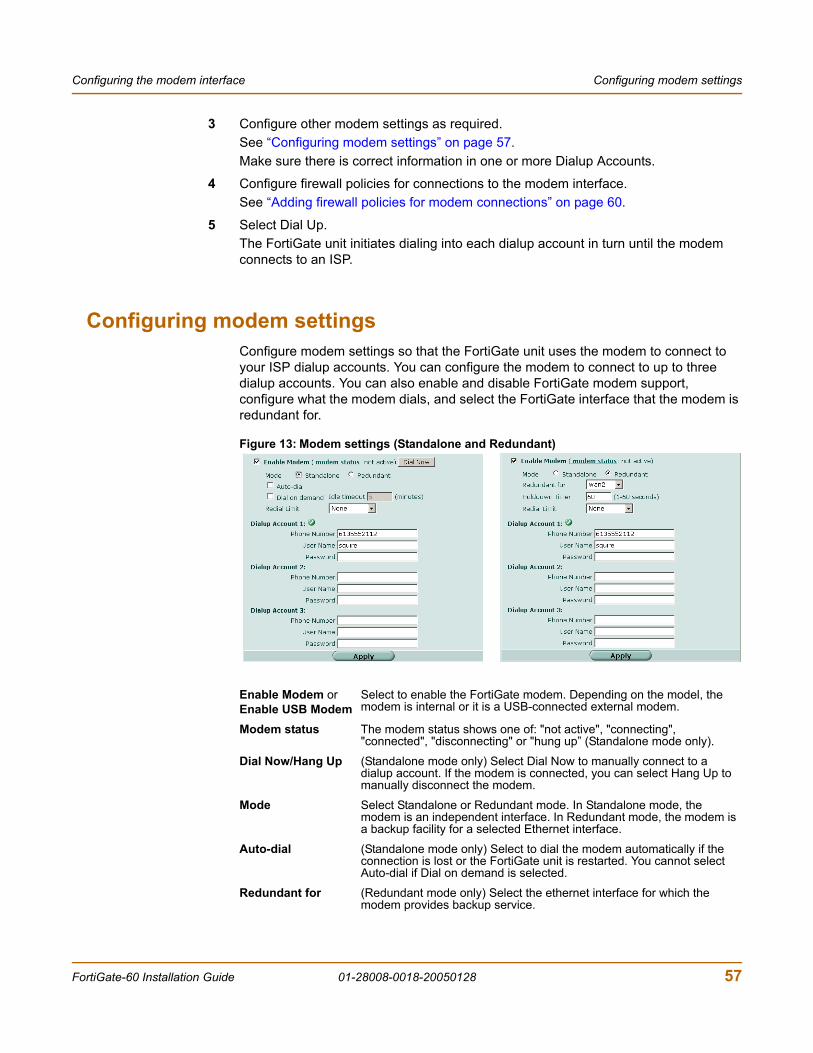
Configuring the modem interface Configuring modem settings
3 Configure other modem settings as required.See “Configuring modem settings” on page 57.Make sure there is correct information in one or more Dialup Accounts.
4 Configure firewall policies for connections to the modem interface.See “Adding firewall policies for modem connections” on page 60.
5 Select Dial Up.The FortiGate unit initiates dialing into each dialup account in turn until the modem connects to an ISP.
Configuring modem settingsConfigure modem settings so that the FortiGate unit uses the modem to connect to your ISP dialup accounts. You can configure the modem to connect to up to three dialup accounts. You can also enable and disable FortiGate modem support, configure what the modem dials, and select the FortiGate interface that the modem is redundant for.
Figure 13: Modem settings (Standalone and Redundant)
Enable Modem orEnable USB Modem
Select to enable the FortiGate modem. Depending on the model, the modem is internal or it is a USB-connected external modem.
Modem status The modem status shows one of: "not active", "connecting", "connected", "disconnecting" or "hung up” (Standalone mode only).
Dial Now/Hang Up (Standalone mode only) Select Dial Now to manually connect to a dialup account. If the modem is connected, you can select Hang Up to manually disconnect the modem.
Mode Select Standalone or Redundant mode. In Standalone mode, the modem is an independent interface. In Redundant mode, the modem is a backup facility for a selected Ethernet interface.
Auto-dial (Standalone mode only) Select to dial the modem automatically if the connection is lost or the FortiGate unit is restarted. You cannot select Auto-dial if Dial on demand is selected.
Redundant for (Redundant mode only) Select the ethernet interface for which the modem provides backup service.
FortiGate-60 Installation Guide 01-28008-0018-20050128 57
Connecting and disconnecting the modem in Standalone mode Configuring the modem interface
You can configure and use the modem in NAT/Route mode only.
To configure modem settings1 Go to System > Network > Modem.
2 Select Enable Modem.
3 Change any of the following dialup connection settings:
4 Enter the following Dialup Account 1 settings:
5 If you have multiple dialup accounts, enter Phone Number, User Name, and Password for Dialup Account 2 and Dialup Account 3.
6 Select Apply.
Connecting and disconnecting the modem in Standalone modeTo connect to a dialup account
1 Go to System > Network > Modem.
2 Select Enable Modem.
3 Make sure there is correct information in one or more Dialup Accounts.
4 Select Apply if you make any configuration changes.
Dial on demand (Standalone mode only) Select to dial the modem when packets are routed to the modem interface. The modem disconnects after the idle timeout period. You cannot select Dial on demand if Auto-dial is selected.
Idle timeout (Standalone mode only) Enter the timeout duration in minutes. After this period of inactivity, the modem disconnects.
HolddownTimer
(Redundant mode only) Enter the time (1-60 seconds) that the FortiGate unit waits before switching from the modem interface to the primary interface, after the primary interface has been restored. The default is 1 second. Configure a higher value if you find the FortiGate unit switching repeatedly between the primary interface and the modem interface.
Redial Limit The maximum number of times (1-10) that the FortiGate unit modem attempts to reconnect to the ISP if the connection fails. The default redial limit is 1. Select None to have no limit on redial attempts.
Dialup Account Configure up to three dialup accounts. The FortiGate unit tries connecting to each account in order until a connection can be established.
Phone Number The phone number required to connect to the dialup account. Do not add spaces to the phone number. Make sure to include standard special characters for pauses, country codes, and other functions as required by your modem to connect to your dialup account.
User Name The user name (maximum 63 characters) sent to the ISP.
Password The password sent to the ISP.
58 01-28008-0018-20050128 Fortinet Inc.
Configuring the modem interface Defining a Ping Server
5 Select Dial Now.The FortiGate unit initiates dialing into each dialup account in turn until the modem connects to an ISP.Modem status is one of the following:
A green check mark indicates the active dialup account.
The IP address and netmask assigned to the modem interface appears on the System Network Interface page of the web-based manager.
To disconnect the modemUse the following procedure to disconnect the modem from a dialup account.
1 Go to System > Network > Modem.
2 Select Hang Up if you want to disconnect from the dialup account.
Defining a Ping ServerAdding a ping server is required for routing failover for the modem in redundant mode. A ping server confirms the connectivity to an ethernet interface.
To add a ping server to an interface1 Go to System > Network > Interface.
2 Choose an interface and select Edit.
3 Set Ping Server to the IP address of the next hop router on the network connected to the interface.
4 Select the Enable check box.
5 Select OK to save the changes.
Dead gateway detection
The FortiGate unit uses dead gateway detection to ping the Ping Server IP address to make sure that the FortiGate unit can connect to this IP address.
Modify dead gateway detection to control how the FortiGate unit confirms connectivity with a ping server added to an interface configuration. For information about adding a ping server to an interface, above.
To modify the dead gateway detection settings1 Go to System > Config > Options.
2 For Detection Interval, type a number in seconds to specify how often the FortiGate unit tests the connection to the ping target.
not active The modem interface is not connected to the ISP.
active The modem interface is attempting to connect to the ISP, or is connected to the ISP.
FortiGate-60 Installation Guide 01-28008-0018-20050128 59
Adding firewall policies for modem connections Configuring the modem interface
3 For Fail-over Detection, type a number of times that the connection test fails before the FortiGate unit assumes that the gateway is no longer functioning.
4 Select Apply.
Adding firewall policies for modem connectionsThe modem interface requires firewall addresses and policies. You can add one or more addresses to the modem interface. For information about adding addresses, see the FortiGate Administration Guide. When you add addresses, the modem interface appears on the policy grid.
You can configure firewall policies to control the flow of packets between the modem interface and the other interfaces on the FortiGate unit. For information about adding firewall policies, see the FortiGate Administration Guide.
60 01-28008-0018-20050128 Fortinet Inc.
FortiGate-60 Installation Guide Version 2.80 MR8
IndexAauto-dial 57
CCLI 6
configuring IP addresses 41configuring NAT/Route mode 30connecting to 17
clusterconnecting 51, 53
command line interface 6configuring redundant mode 55configuring standalone mode 56connect
cluster 51, 53connecting
to network 34, 44web-based manager 16
customer service 10
Ddefault gateway
configuring (Transparent mode) 42default route 20dial now 57dial on demand 58
Eenvironmental specifications 15
Ffirewall policies
modem 60firewall setup wizard 6, 28, 32, 40, 43
starting 29, 34, 40, 43Fortinet customer service 10
HHA
configuring FortiGate units for HA operation 47connecting an HA cluster 51, 53
hang up 57High availability 47holddown timer 58HTTPS 6
Iinternal network
configuring 36IP addresses
configuring from the CLI 41
Llease duration
DHCP 20
Mmanagement IP address
transparent mode 42modem
adding firewall policies 60configuring settings 57redundant mode 55standalone mode 55, 56
NNAT/Route mode
configuration from the CLI 30NTP 37, 45NTP server 37, 45
Pping server 59power requirements 15powering on 15
Rredial limit 58redundant mode
configuring 55modem 55
FortiGate-60 Installation Guide 01-28008-0018-20050128 61
Index
Sset time 37, 45setup wizard 28, 32, 40, 43
starting 29, 34, 40, 43standalone mode
configuring 56modem 55, 56
starting IPDHCP 20
synchronize with NTP server 37, 45
Ttechnical support 10
time zone 37, 45Transparent mode
changing to 41configuring the default gateway 42management IP address 42
Wweb-based manager 6
connecting to 16introduction 6
wizardsetting up firewall 28, 32, 40, 43starting 29, 34, 40, 43
62 01-28008-0018-20050128 Fortinet Inc.