formulations, interface properties, utilities and output
TRANSCRIPT

HyperWorks Best Practice
www.altairhyperworks.de/BestPractice
OptiStruct ContactFormulations, Interface
Properties, Utilities and Output
Gunter Warmbier
Senior Application Engineer
Altair Engineering
Köln, 13.11. 2015

Copyright © 2015 Altair Engineering, Inc. Proprietary and Confidential. All rights reserved.
2
Agenda
1. Formulation and Interface Properties
- Small Sliding and Finite Sliding Contact
- Contact Discretization
- Node-To-Surface and Surface-To-Surface Discretization
- Contact Interface Properties
- SLIDE, STICK, and TIE Formulations
2. Utilites and Outputs
- ADJUST Utility
- CLEARANCE Utility
- SMOOTHING Utility
- Contact Stabilization
- Contact and Element Formulations
- Contact Output

Copyright © 2015 Altair Engineering, Inc. Proprietary and Confidential. All rights reserved.
3
Why do we need contacts?
• To avoid components passing through each other
• Contact pressure resists penetration
• Frictional shear resists sliding
There are several difficult issues associated with contact analysis
• Large changes in contact stiffness
• Discontinuity in stiffness
• Highly nonlinear phenomenon
• Thermal conductance properties change with contact
Introduction to Contacts

Copyright © 2015 Altair Engineering, Inc. Proprietary and Confidential. All rights reserved.
4
Small Sliding and Finite Sliding Contact
What is small sliding contact?
• Relative sliding between master and slave surfaces are relatively small (<1elem size)
• Slave nodes interact with only small number of master surface nodes
• Large contact changes not expected, so contact search performed only at beginning
of analysis
The difference between small sliding and finite sliding contact changes the
analysis contact parameters
• In small sliding, the relationship between master surface and slave nodes is initiated
at the very start of the analysis, and the relationship of which slave nodes will interact
with master elements is not updated throughout the course of the analysis
• In finite sliding, the master surface segments and their interactions with slave nodes
are updated throughout the course of the analysis. This allows arbitrary large sliding
and rotations as a part of the analysis.

Copyright © 2015 Altair Engineering, Inc. Proprietary and Confidential. All rights reserved.
5
Contact Discretization
What is contact discretization?
• Contact discretization is the process whereby OptiStruct converts a contact interface
to a group of contact elements
• With a user-defined contact interface, OS creates a group of internal contact elements
and applies contact conditions with these internal contact elements
• The selection of discretization approach, i.e., node-to-surface (N2S) or surface-to-
surface (S2S), significantly affects how the contact elements are created and what the
contact elements look like which, in turn, affects the analytical computation
CONTACT CTIDPID/TYPE/
MU1SSID MSID MORIENT SRCHDIS ADJUST CLEARANCE
DISCRET

Copyright © 2015 Altair Engineering, Inc. Proprietary and Confidential. All rights reserved.
6
Contact Discretization
Contact discretization for node-to-surface elements (N2S) utilizes the
following structure:
where N2S contact element is described using the following entities:
• One slave node
• A few master nodes
• One master face including the master nodes
• One projection from the slave node to the master face

Copyright © 2015 Altair Engineering, Inc. Proprietary and Confidential. All rights reserved.
7
Contact Discretization
Searching for contact elements in N2S contact formulation follows a
prescribed sequence
• For each slave node, a respective master segment will be searched which contains the
normal projection of the slave and is within SEARCHDIS distance from slave node
• If no master within the normal projection is found, then the nearest segment is picked which
is within 30 degrees relative to the normal to master segment
• Once a feasible master is found, contact element is created.
master
slave
n
z y
x

Copyright © 2015 Altair Engineering, Inc. Proprietary and Confidential. All rights reserved.
8
Contact Discretization
Some additional notes about using contact elements in a N2S formulation
• For small displacement analysis, contact element is implemented with CGAPG as the core
• For large displacement analysis, contact elements are implemented with a type of internal
element (different than CGAPG) as the core
• The above small and large displacement implementations are valid for all subcase types
• Different contact elements have different slave nodes but each contact element has a
unique slave node
• Different contact elements may share the same master face

Copyright © 2015 Altair Engineering, Inc. Proprietary and Confidential. All rights reserved.
9
Contact Discretization
Surface-to-surface (S2S) formulations differ from N2S setup in the following:
S2S contact elements are or can be comprised of the following:
• One “core” slave node
• Several slave nodes surrounding the “core” slave node
• One or more slave faces including the salve nodes and sharing the “core” slave node
• Several master nodes
• One or more master faces including the master nodes
• One or more projections from the slave faces to the master faces

Copyright © 2015 Altair Engineering, Inc. Proprietary and Confidential. All rights reserved.
10
Contact Discretization
Searching for contact elements in S2S contact formulation follows the steps
below:
• For each slave facet, a respective master facet will first be searched which contains the
normal projection of sample points on the slave facet and is within SEARCHDIS distance
from the sample points. Then contact interface is created.
• For each slave node, the contact element is created with the surrounding slave facets and
the master facets found by projection of the sample points on the slave facets.
• The structure of S2S contact element is different when compared to that of CGAPG
element.

Copyright © 2015 Altair Engineering, Inc. Proprietary and Confidential. All rights reserved.
11
Contact Discretization
Additional notes about contact elements in S2S:
• Different contact elements have different “core” slave nodes, i.e., each contact element
has its unique “core” slave node
• Different contact elements may share one or more slave face(s)
• Different contact elements may share one or more master face(s)

Copyright © 2015 Altair Engineering, Inc. Proprietary and Confidential. All rights reserved.
12
Contact Discretization
The following points will aid in selecting between Node-to-Surface and
Surface-to-Surface discretization formulations for a given contact definition
• The finer mesh is suggested to be slave for N2S
• S2S is usually more expensive than N2S in both space and time, but it could produce
smoother contact pressure in many cases
• When the slave is a SET of GRIDs, the discretization has to be N2S.
• When the slave is a SET of solid elements, the discretization is suggested be N2S.
Alternatively, use surfaces of solid elements instead of the solid elements themselves as
the slave of a S2S contact interface.
• When the slave or master surface includes corner, the discretization is suggested to be
N2S. Alternatively, split the surface into some smaller smooth surfaces and use them as
the slaves or masters of S2S contact interfaces.

Copyright © 2015 Altair Engineering, Inc. Proprietary and Confidential. All rights reserved.
13
Contact Discretization
Visualizing contacts for a results solution is dependent on the type of contact
formulation used
For N2S Contacts in small displacement:
• For N2S contacts, CGAPG elements are created internally
• To visualize the CGAPG elements created, add CONTPRM, CONTGAP, YES in your input
file. A filename_root.contgap.fem will be created which can be imported in HM to visualize
these gap elements
For all S2S Contacts and N2S contacts in large displacement:
• The contact elements created for S2S contacts are different in structure than CGAPG
elements
• For purposes of visualization ONLY, RBE3 + PLOTEL elements are created which can be
obtained using CONTPRM, CONTOUT, YES in input deck. These elements are NOT
created internally for S2S contacts/N2S large disp
• This visualization of RBE3+PLOTEL elements for S2S/N2S large disp contacts will be
available from 14.0

Copyright © 2015 Altair Engineering, Inc. Proprietary and Confidential. All rights reserved.
14
Contact Discretization
Case Study : Blocks in contact: N2S vs S2S
The comparison shows a more even distribution of contact pressure for S2S
as compared to N2S
S2S N2S
• Bottom is slave
• Top is master
• Enforced displacements on top

Copyright © 2015 Altair Engineering, Inc. Proprietary and Confidential. All rights reserved.
15
Contact Discretization
When the master and slave surfaces are switched, the results show a different
contact pressure distribution
Surface-to-Surface (S2S) is less sensitive to the choice of master/slave in a
pairing than N2S
• Bottom is master
• Top is slave
S2S N2S
Copyright © 2015 Altair Engineering, Inc. Proprietary and Confidential. All rights reserved.
16
Contact Interface Properties
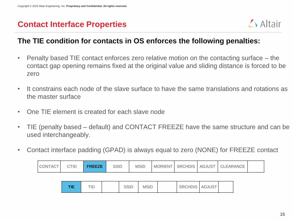
The TIE condition for contacts in OS enforces the following penalties:
• Penalty based TIE contact enforces zero relative motion on the contacting surface – the
contact gap opening remains fixed at the original value and sliding distance is forced to be
zero
• It constrains each node of the slave surface to have the same translations and rotations as
the master surface
• One TIE element is created for each slave node
• TIE (penalty based – default) and CONTACT FREEZE have the same structure and can be
used interchangeably.
• Contact interface padding (GPAD) is always equal to zero (NONE) for FREEZE contact
CONTACT CTID FREEZE SSID MSID MORIENT SRCHDIS ADJUST CLEARANCE
TIE TID SSID MSID SRCHDIS ADJUST

Copyright © 2015 Altair Engineering, Inc. Proprietary and Confidential. All rights reserved.
17
Contact Interface Properties
Compressive load
Tensile load
When the contact interface TYPE is set to FREEZE or TIE:
• OS maintains enforced zero relative displacement
on that interface (both closed and open contacts)
• The analysis type is limited to linear analysis
• Master and slave remain tied during entire duration
of analysis
• Contact type FREEZE is available for use with
Normal Modes analysis also
Copyright © 2015 Altair Engineering, Inc. Proprietary and Confidential. All rights reserved.
18
Contact Interface Properties
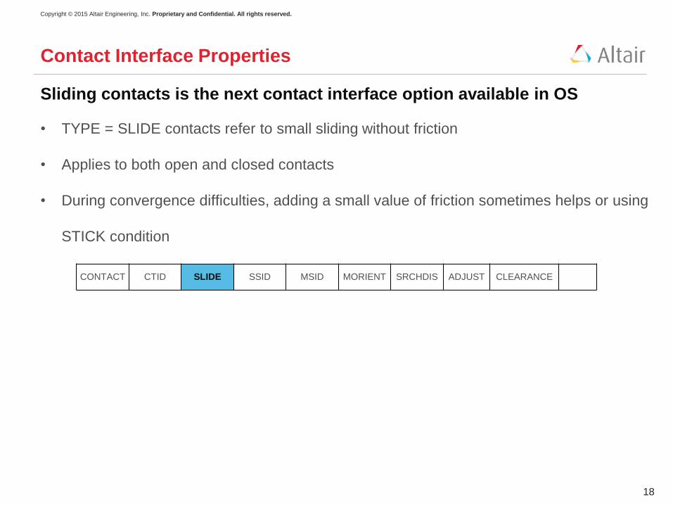
Sliding contacts is the next contact interface option available in OS
• TYPE = SLIDE contacts refer to small sliding without friction
• Applies to both open and closed contacts
• During convergence difficulties, adding a small value of friction sometimes helps or using
STICK condition
CONTACT CTID SLIDE SSID MSID MORIENT SRCHDIS ADJUST CLEARANCE

Copyright © 2015 Altair Engineering, Inc. Proprietary and Confidential. All rights reserved.
19
Contact Interface Properties
STICK is another major type of contact interface parameter available in OS
• TYPE = STICK is interpreted as enforced stick condition
• Such contacts will not enter into sliding phase
• Enforced stick only applies to contacts that are closed
• The contact stiffness KT is (0.1 * STIFF) in case of STICK
CONTACT CTID STICK SSID MSID MORIENT SRCHDIS ADJUST CLEARANCE

Copyright © 2015 Altair Engineering, Inc. Proprietary and Confidential. All rights reserved.
20
Contact Interface Properties
No separation contact conditions (NOSEP) can be applied to both open and
closed S2S contacts
• TYPE = NOSEP contacts refer to no separation interface behavior
• The slave and master surfaces do not separate but are bonded for the entire course of
simulation
• Once the contact pair comes into contact, they can slide against each other without friction
• This works for S2S contacts only
CONTACT CTID NOSEP SSID MSID MORIENT SRCHDIS ADJUST CLEARANCE

Copyright © 2015 Altair Engineering, Inc. Proprietary and Confidential. All rights reserved.
21
Contact Interface Properties
Case Study : NOSEP vs STICK vs SLIDE
• S2S contact defined on blocks
• Loading applied on top block at center of RBE3
• Subcase 1 : Compressive Load (-ve Z direction)
No Separation Stick Slide

Copyright © 2015 Altair Engineering, Inc. Proprietary and Confidential. All rights reserved.
22
Contact Interface Properties
No Separation Stick Slide
Case Study : NOSEP vs STICK vs SLIDE
• S2S contact defined on blocks
• Loading applied on top block at center of RBE3
• Subcase 2 : Tensile load (ve Z direction), continued from Subcase 1

Copyright © 2015 Altair Engineering, Inc. Proprietary and Confidential. All rights reserved.
23
Contact Interface Properties
No Separation Stick Slide
sliding
Case Study : NOSEP vs STICK vs SLIDE
• S2S contact defined on blocks
• Loading applied on top block at center of RBE3
• Subcase 3 : Lateral (+ve Y direction), continued from Subcase 2

Copyright © 2015 Altair Engineering, Inc. Proprietary and Confidential. All rights reserved.
24
Contact Utilities - ADJUST
Contact ADJUST parameter allows slave nodes to precisely contact the
master surface
• This does not cause any strain in the model
• It is useful to eliminate small gaps or penetrations caused by preprocessors
• This helps contacts get engaged and prevent any rigid body motion
• It should NOT be used to correct any gross errors in mesh
• ADJUST should be specified in CONTACT or TIE cards
CONTACT CTID
PID/
TYPE/
MU1
SSID MSID MORIENT SRCHDIS ADJUST CLEARANCE
TIE TID SSID MSID SRCHDIS ADJUST

Copyright © 2015 Altair Engineering, Inc. Proprietary and Confidential. All rights reserved.
25
When ADJUST specified is > 0.0
Slave nodes within the adjustment depth (gaps and penetrations) are moved to lie precisely on
master surface
Contact Utilities - ADJUST

Copyright © 2015 Altair Engineering, Inc. Proprietary and Confidential. All rights reserved.
26
Contact Utilities - ADJUST
When ADJUST specified is = 0.0
Only slave nodes within the specified adjustment depth that penetrate the master are moved
to lie precisely on master surface

Copyright © 2015 Altair Engineering, Inc. Proprietary and Confidential. All rights reserved.
27
Contact Utilities - ADJUST
Additional information about using the ADJUST parameter in contact analysis
• For N2S contact, ADJUST is treated as a change in initial model geometry and adjustment
of grids can be visualized
• For S2S contact, ADJUST is treated as a change in initial contact opening/penetration (the
slave nodes are not adjusted rather an internally shifted surface is used to enforce contact)
• ADJUST can also be specified to be automatic (AUTO) – where 5% of the average edge
length on master surface is assigned as adjustment depth
• To obtain a bulk data file that contains the grid sets that are adjusted as well as new
coordinates of contact grids after adjustment use CONTPRM, ADJGRID, YES

Copyright © 2015 Altair Engineering, Inc. Proprietary and Confidential. All rights reserved.
28
Contact Utilities - ADJUST
Case Study: Connecting Rod – Bolt Pretension
No Adjust With Adjust

Copyright © 2015 Altair Engineering, Inc. Proprietary and Confidential. All rights reserved.
29
Contact Utilities - CLEARANCE
The CLEARANCE utility allows user-specified precise initial clearance or
overclosure values
• These values can be defined either in the CONTACT or PCONT cards
• Positive CLEARANCE is equal to the distance that slave and master surfaces have to
move towards each other in order to close the contact
• Using CLEARANCE overrides the default contact behavior or calculating the initial gap
opening from the actual distance between slave and master
• It is important to pick the right SEARCHDIS so that only desired slave master pairs are
involved – else all contact elements even though whose slaves are geometrically distant
from the respective master, will be considered
• Negative CLEARANCE indicates contacting bodies have initial penetrations and is equal to
resolving interference-fit / press-fit problems
CONTACT CTID
PID/
TYPE/
MU1
SSID MSID MORIENT SRCHDIS ADJUST CLEARANCE
PCONT PID GPAD STIFF m1 m2 CLEARANCE

Copyright © 2015 Altair Engineering, Inc. Proprietary and Confidential. All rights reserved.
30
Contact Utilities - CLEARANCE
The activation of the CLEARANCE utility is dependent on the parameter value
• For a CLEARANCE value of 0.0, contact
becomes active immediately, irrespective of
actual gap between slave and master
surfaces
• For a positive CLEARANCE of 0.07,
contact becomes active once the relative
displacement between slave and master
becomes 0.07Constant gap
= 0.1mm
CLEARANCE = 0.0 CLEARANCE = 0.07

Copyright © 2015 Altair Engineering, Inc. Proprietary and Confidential. All rights reserved.
31
Contact Utilities - CLEARANCE
w/o clearance
with clearance
w/o clearance
with clearance
Contact pressure
analysis using clearance
Interference-fit using clearance

Copyright © 2015 Altair Engineering, Inc. Proprietary and Confidential. All rights reserved.
32
Contact Utilities - SMOOTHING
Smoothing improves the approximation of smooth surface behavior
(continuous normal) from the FE discretized surface (discontinuous normal)
• Curved surfaces in contact are approximated as group of faceted element faces. The use
of faceted surface rather than true surface can contribute to inaccuracy in contact stress
and contact pressure distributions
• This only applies to S2S contact surfaces, can be applied to the master/slave surfaces as a
whole or can be applied over certain regions of the surfaces
• Contact stress and contact pressure distributions are usually improved with smoothing
• Smoothing is defined under CONTACT card and does not apply to FREEZE contacts, or
when ADJUST or CLEARANCE is specified
CONTACT CTID
PID/
TYPE/
MU1
SSID MSID MORIENT SRCHDIS ADJUST CLEARANCE
+ SMOOTH SMSIDE SMREG

Copyright © 2015 Altair Engineering, Inc. Proprietary and Confidential. All rights reserved.
33
Contact Utilities - SMOOTHING
Case Study: Resolving initial interference
No Smoothing Smoothing
No Smoothing Smoothing
Stresses look much more
uniform with contact smoothing
Contact pressure distribution is
more uniform with smoothing

Copyright © 2015 Altair Engineering, Inc. Proprietary and Confidential. All rights reserved.
34
Contact Stabilization
Stabilization for contacts helps to correct any initial rigid body motion
• Effective in overcoming temporary instabilities that occur mid-analysis or end-of-analysis
• Can be applied globally to all subcases or can be subcase dependent
• Two ways to define the stabilization:
• PARAM, EXPERTNL, CNTSTB
• CNTSTB Bulk card
• PARAM, EXPERTNL, CNTSTB applies weak springs on all the contacts and then releases
it to zero
• CNTSTB defines damping stabilization parameters in normal and tangential directions
(based on contact penalty stiffness) for the contacts
CNTSTB ID APSTB LMTGAP S0 S1
SCALE TFRAC

Copyright © 2015 Altair Engineering, Inc. Proprietary and Confidential. All rights reserved.
35
Contact Stabilization
Additional notes about stabilization in contact solutions:
• For N2S contacts in small displacement analysis, use PARAM, EXPERTNL, CNTSTB
• For N2S contacts in large displacement analysis and S2S contacts in small/large
displacement analysis, using PARAM, EXPERTNL, CNTSTB activates the stabilization
parameters used in CNTSTB
• For temporary instabilities that might occur at the end of analysis, you can specify S1
(scale factor for stabilization at end of subcase) to be a non-zero value
• For convergence difficulties, may also change the default tangential stabilization factor
TRFAC (default = 0.1)
CNTSTB ID APSTB LMTGAP S0 S1
SCALE TFRAC

Copyright © 2015 Altair Engineering, Inc. Proprietary and Confidential. All rights reserved.
36
Contact and Element Formulations
The tetra10 element formulation is contact-friendly and has an improved
formulation
• Improved formulation uses modified shape functions
• Suitable for elastic and elasto-plastic applications
• Other contact-friendly element formulations include hexa20 and penta15
• These elements can be activated via PARAM, CONTFEL, YES
• These elements may be combined in one model
STANDARD IMPROVED

Copyright © 2015 Altair Engineering, Inc. Proprietary and Confidential. All rights reserved.
37
Contact Output
Many types of contact results can be output using the OS control cards
• Contact pressure, open/closed status, stick/slip status, forces, frictional traction,
penetration, ….
• CONTF(PCONT), CONTF(FRICT), CONTF(FORCE), CONTF(ALL)
To show results on both sides of contact, respective projections must be
designed
Contact Opening – other solver
Contact Opening - OptiStruct

Copyright © 2015 Altair Engineering, Inc. Proprietary and Confidential. All rights reserved.
38
Contact Output
Additional notes on contact output through control cards in OptiStruct
• Contact/gap Open/Closed status is represented by 0.0 for Open and 1.0 for Closed.
Intermediate values indicate transition from open to closed across individual elements.
• Slip/Stick Status is represented by 0.0 for Open, 1.0 for Slip and 2.0 for Stick. Intermediate
values indicate transition from open to closed across individual elements
• Sliding Distance represents total sliding distance accumulated while the surfaces are in
contact. This may be different than just the difference in displacements between the
starting and final position.
• An ascii file named filename_.cntf file is also available which output the total contact forces

Copyright © 2015 Altair Engineering, Inc. Proprietary and Confidential. All rights reserved.
39
Contact Output
These examples show contact outputs being post-processed in HyperView
Frictional Shear
Contact Force
Copyright © 2015 Altair Engineering, Inc. Proprietary and Confidential. All rights reserved.
40
Contact Output
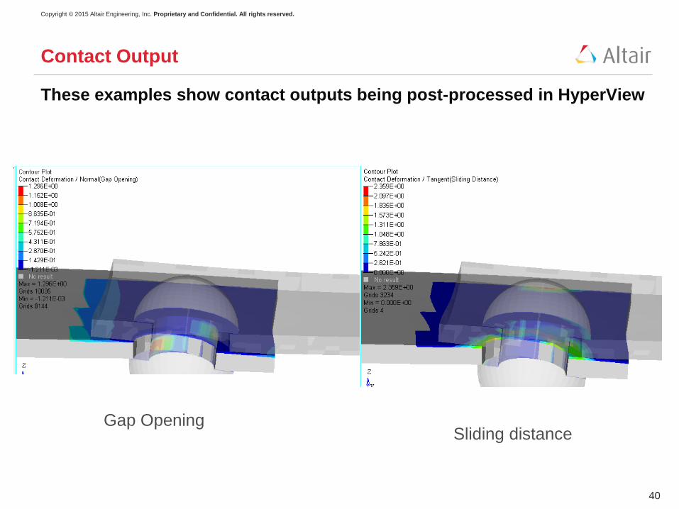
These examples show contact outputs being post-processed in HyperView
Gap OpeningSliding distance

Copyright © 2015 Altair Engineering, Inc. Proprietary and Confidential. All rights reserved.
41
Contact Best Practices and Limitations
When would you use finite sliding contact vs small sliding:
• When arbitrary large changes in contact deformation expected
• When sliding is > 1elem size
• For any type of self-contact
OS currently solves small sliding contact problems - finite sliding is to be implemented
as a part of OptiStruct 14.0