formulation development of high strength gel system and...
TRANSCRIPT

Research ArticleFormulation Development of High Strength Gel Systemand Evaluation on Profile Control Performance for High Salinityand Low Permeability Fractured Reservoir
Chengli Zhang,1 Guodong Qu,1 and Guoliang Song2
1School of Petroleum Engineering, Northeast Petroleum University, Daqing 163318, China2School of Mathematics and Statistics, Northeast Petroleum University, Daqing 163318, China
Correspondence should be addressed to Guoliang Song; [email protected]
Received 10 December 2016; Revised 13 April 2017; Accepted 19 April 2017; Published 16 May 2017
Academic Editor: Valentina Venuti
Copyright © 2017 Chengli Zhang et al.This is an open access article distributed under the Creative Commons Attribution License,which permits unrestricted use, distribution, and reproduction in any medium, provided the original work is properly cited.
For the large pores and cracks of reservoirs with low temperatures, high salinity, and low permeability, a new type of high strengthgel ABP system is developed in this paper. The defects of conventional gels such as weak gel strength, no gelling, and easydehydration are overcome under the conditions of low temperature and high salinity.The temperature and salt resistance, pluggingcharacteristics, and EOR of the gel system are studied. Under the condition of 32∘C and 29500mg/L salinity, the ABP systemformulation is for 0.3% crosslinking agent A + 0.09% coagulant B + 3500mg/L polymer solution P. The results show that whenthe temperature was increased, the delayed crosslinking time of the system was shortened and the gel strength was increased. Thegood plugging characteristics of the ABP system were reached, and the plugging rate was greater than 99% in cores with differentpermeability. A good profile control performance was achieved, and the recovery rate was improved by 19.27% on the basis of waterflooding. In the practical application of the gel system, the salinity of formationwater and the permeability of fractures are necessaryto determine the appropriate formulation.
1. Introduction
With the rapid development of the economy, oil demand hasincreased greatly, and the exploration and development of theoilfield are becoming more and more complex [1]. The lowpermeability reservoir will be the major object of develop-ment in the future [2]. A large number of fractures often existin low permeability reservoirs [3]. Water channeling, watersubmerging, and so on are often caused by water floodingin the development process [4]. So water shutoff and profilecontrolmeasures need to be applied to the oil andwater wells,and then the oil recovery of low permeability reservoirs isfurther improved [5–8]. The polymer gel system has beensuccessfully used in some cases, such as in reservoirs withnatural fractures [9], water-coning situations [10], carbonatereservoirs [11], open-hole horizontal wells [12], multizonewells [13], gas shutoff in an open-hole gravel pack [14],and acting as annular barriers [15]. Seright and Martinexplained the effects of pH, rock permeability, and lithology
on the performance of a resorcinol/formaldehyde gel [16].The traditional single crosslinking system was reacted withpolyacrylamide solution to form a gel, which is unfavorablyapplied in the field due to the single characteristics andmany other restrictions [17, 18]. A water shutoff gel systemformed with polyacrylamide and polyamine crosslinkingagent, which provided sufficient gel times at less than 80∘F,was presented by Reddy et al. [19]. Though a good pluggingeffect was reached by the SMA gel system, it was only suitablefor low salinity (about 4000mg/L) [20]. A formaldehydephenolic resin prepolymer as high strength gel system waseasily dehydrated under the condition of high salinity water,and, at a low temperature (less than 60∘C), weak strength gel,or even no gel, may be formed by the viscoelastic polymersystem [21].
JY oilfield located in the northwest of China belongsto the low permeability oilfields with low temperature andhigh salinity, with an average temperature, salinity, and
HindawiInternational Journal of Analytical ChemistryVolume 2017, Article ID 2319457, 9 pageshttps://doi.org/10.1155/2017/2319457

2 International Journal of Analytical Chemistry
permeability of 32∘C, 29500mg/L, and 10mD. The develop-ment degree of primary fracture is medium. The width andpermeability of fractures are, respectively, about 0.02mm∼20mm and 300mD∼1000mD. And a conventional systemwas difficult to use to implement profile control and watershutoff because of poor adaptability and short valid period.In this paper, according to the characteristics of JY oilfield,a high strength gel formulation of ABP system is developedsuitable for reservoirs with low temperature, high salinity,and low permeability. Its performance was evaluated, andthe disadvantages of the single system and traditional profilecontrol agent were overcome.
2. Experimental Materials and Methods
The different concentrations of the crosslinking agent A(0.2%, 0.3%, and 0.4%) and coagulant B (0.05%, 0.09%, and0.13%) were prepared in a laboratory. The crosslinking agentA is a cationic sulfonated phenolic resin, and its chemicalstructural formula is as follows:
OH OH
CH3CH2
CH2CH3
CH2CH3
CH2
N+ CH2SO3Na
The coagulant B is phenolic resin produced by thecondensation reaction of formaldehyde and phenol, and itschemical structural formula is as follows:
OH
OHHO CH2 CH2n
The polymer P was partially hydrolyzed polyacrylamide(HPAM), and the relative molecular weight was 25 million.According to the experimental schemes and requirements,the polymer solution of different concentrations (1500mg/L,2500mg/L, and 3500mg/L) was formulated.
The simulated formation oil of JY oilfield was usedin the following experiments, and the average viscosity at32∘C was 2.6mPa⋅s after the dehydration and degassing. Thesimulated formation water of JY oilfield was used in theexperiments, and its salinity was 15000mg/L, 29500mg/L,and 45000mg/L, respectively.
For studying the fracture system of the low permeabilityreservoir, the high permeability cores are 300mD, 500mD,and 1000mD, respectively, for simulating the fracture sys-tems.The low permeability cores are 10mD for simulating thelow permeability formation.
AnHW-4A type double thermostat was used to maintainthe temperature of the high strength gel system.The viscosityof the high strength gel was measured by a Brookfield DV
Scheme 1Scheme 2Scheme 3
0500
100015002000250030003500400045005000
Visc
osity
(mPa
·s)
5 10 15 20 250Time (d)
Figure 1:The changing process of viscosity when the concentrationof polymer P was 1500mg/L.
III ultra-type rotary viscometer. The solution was stirredevenly by a JJ-1 type electric mixer.The rock flow experimentdevice was applied to evaluate the sealing characteristics ofthe high strength gel system and conduct the oil displacementexperiment.
3. Results and Discussions
3.1. Experiment 1: Determination of High Strength Gel Formu-lation in Low Temperature and High Salinity Water
3.1.1. Experimental Procedure
(1) The solution of polymer P, crosslinking agent A, andcoagulant B were mixed in accordance with the ratioof the experimental schemes and stirred evenly.
(2) The mixed solutions were placed in a thermostatpreheated to 32∘C.
(3) The viscosity of the gel system was measured by thetime steps.
3.1.2. When the Concentration of Polymer P Was 1500mg/L.The initial viscosity of the gel system was 12.0mP⋅s whenthe concentration of polymer P was 1500mg/L. The threeexperimental schemes were designed under the conditions ofdifferent ratios of crosslinking agent A and coagulant B. Thegelling process is shown in Figure 1.
Scheme 1. The concentrations of polymer P, crosslinkingagent A, and coagulant B were 1500mg/L, 0.2%, and 0.05%,respectively.
Scheme 2. The concentrations of polymer P, crosslinkingagent A, and coagulant B were 1500mg/L, 0.3%, and 0.09%,respectively.
Scheme 3. The concentrations of polymer P, crosslinkingagent A, and coagulant B were 1500mg/L, 0.4%, and 0.13%,respectively.

International Journal of Analytical Chemistry 3
Scheme 4Scheme 5Scheme 6
0100020003000400050006000700080009000
10000
Visc
osity
(mPa
·s)
5 10 15 20 250Time (d)
Figure 2:The changing process of viscosity when the concentrationof polymer P was 2500mg/L.
The initial viscosity of the system was low due to theconcentration limits of the polymer solution. As a result ofthe electrostatic shield effect, polymer molecular chains werecurled up significantly under the condition of high salinity,and the distance between molecules of the polymer wasrelatively enlarged [22]. Then the crosslinking agent actingas bridge could not function effectively.The characteristics ofviscosity reduction were displayed obviously, and the gellingtime was extended.
For schemes 2 and 3, due to the low polymer concentra-tion and relatively high concentrations of crosslinking agentand coagulant, the initial viscosity of the gel system increasedso fast that the viscosity reduction followed in a short time.The phenomenon of excessive crosslinking was evidenced bythe shrinking of the net structure [23]. And then the waterenclosed in the gel was squeezed out. The dehydration wasexhibited in the early stages. It was indicated that the amountof coagulant and crosslinking agent should be moderate sothat the phenomenon of excessive crosslinking would beavoided under a certain polymer concentration. In scheme 1,a slow downward trend of viscosity was displayed with timeprolonging, and good viscosity stability was maintained. Thegelling time was 6-7 days. The gel strength was well main-tained, but the results were far from meeting the standard ofhigh strength gel (viscosity > 10000mPa⋅s).
3.1.3. When the Concentration of Polymer P Was 2500mg/L.The initial viscosity was 22.6mP⋅s when the concentration ofpolymer P was 2500mg/L. The three experimental schemeswere designed under the conditions of different ratios ofcrosslinking agent A and coagulant B. The gelling process isshown in Figure 2.
Scheme 4. The concentrations of polymer P, crosslinkingagent A, and coagulant B were 2500mg/L, 0.2%, and 0.09%,respectively.
Scheme 5. The concentrations of polymer P, crosslinkingagent A, and coagulant B were 2500mg/L, 0.3%, and 0.13%,respectively.
Scheme 6. The concentrations of polymer P, crosslinkingagent A, and coagulant B were 2500mg/L, 0.4%, and 0.05%,respectively.
For schemes 4 and 5, the viscosity of the system did notincrease. The agglomeration and precipitation of coagulantoccurred with that. The analysis showed that when theamount of coagulant was relatively greater, namely, that theratio of crosslinking agent and coagulant was less than 3 : 1,the reaction activation energy of the crosslinking agent andcoagulant molecular was reduced due to low temperatureand a large number of divalent metal ions. The coagulantcould not be reacted with crosslinking agent, there was nocrosslinking for a long time, the coagulant was precipitated,and, ultimately, the crosslinking failed. Therefore, when theproportion of crosslinking agent and coagulant was less than3 : 1, and low temperature and high salinity were presentedat the same time, the high strength gel could not be formed.When the concentration of polymer P was 2500mg/L, the8500mPa⋅s could be reached by adding moderate amountof crosslinking agent and coagulant, and the gelling timewas 5-6 days. The gel strength was well maintained, but thestandard of high strength gel (viscosity > 10000mPa⋅s) wasnot achieved.
As can be seen from the experimental schemes 1–6,the delayed crosslinking time decreases with the increaseof polymer concentration and the amount of crosslinkingagent. The coagulant should not be used excessively, andthe reasonable proportion of the crosslinking agent andcoagulant should bemore than 3 : 1.The gel stability increaseswith the polymer concentration, when the amounts of thecrosslinking agent and coagulant increase, and the gel sta-bility initially increases and then decreases. The greater theinitial viscosity of the system is, the better the gelling effectis. Otherwise, the phenomenon of polymermolecular curlingwill be exhibited, intermolecular distances will be extended,and then crosslinking points of molecular will be decreasedunder the condition of high salinity.
3.1.4. When the Concentration of Polymer P Was 3500mg/L.According to the above experimental analysis and results,schemes 7–9 were designed under the conditions that theratio of crosslinking agent A and coagulant B is more than3 : 1. The initial viscosity was 33.0mPa⋅s when the concen-tration of polymer P was 3500mg/L. The gelling process isshown in Figure 3.
Scheme 4. The concentrations of polymer P, crosslinkingagent A, and coagulant B were 3500mg/L, 0.2%, and 0.05%,respectively.
Scheme 5. The concentrations of polymer P, crosslinkingagent A, and coagulant B were 3500mg/L, 0.3%, and 0.09%,respectively.
Scheme 6. The concentrations of polymer P, crosslinkingagent A and coagulant B were 3500mg/L, 0.4%, and 0.13%,respectively.
When the concentration of polymer P was 3500mg/L,and the proportion of the crosslinking agent A and coagulant

4 International Journal of Analytical Chemistry
Table 1: The experimental results of different ABP systems in 29500mg/L salinity water.
Formulations Delayedcrosslinking
time(days)
Gel strength(mPa⋅s)
Initialviscosity(mPa⋅s)
Stability(days)Scheme
numberPolymer P(mg/L)
Crosslinkingagent A(%)
Coagulant B(%)
1 1500 0.2 0.05 7-8 >4000 12.0 >302 1500 0.3 0.09 7-8 >2000 12.0 >303 1500 0.4 0.13 6-7 >1000 12.0 >304 2500 0.2 0.09 — — 22.6 —5 2500 0.3 0.13 — — 22.6 —6 2500 0.4 0.05 5-6 >8500 22.6 >607 3500 0.2 0.05 5-6 >13000 33.0 >608 3500 0.3 0.09 5-6 >14500 33.0 >609 3500 0.4 0.13 3-4 >10500 33.0 >60
Scheme 7Scheme 8Scheme 9
5 10 15 20 250Time (d)
02000400060008000
10000120001400016000
Visc
osity
(mPa
·s)
Figure 3:The changing process of viscosity when the concentrationof polymer P was 3500mg/L.
B was more than 3 : 1, the standard of high strength gelcould be achieved. The gelling time was prolonged, and thegel stability was well maintained. Compared with scheme8, the dosages of the crosslinking agent A and coagulant Bwere slightly lower in scheme 7, and the gel strength wascorrespondingly lower than that of the scheme 8. The gelstrength of scheme 8 was 14500mPa⋅s and the highest inthe 9 schemes. The slightly higher amounts of crosslinkingagent A and coagulant B were used in scheme 9.The reactionactivation energy decreased, so the gel strength was lowerthan that of schemes 7 or 8. The experimental results ofdifferent formulations under the conditions of 32∘C and29500mg/L salinity are shown in Table 1.
The results can be obtained in summary of the experi-mental schemes 1–9:
(1) The delayed crosslinking time decreases with theincrease of polymer concentration and the amountof crosslinking agent A. Under a certain polymerconcentration, the amounts of crosslinking agent Aand coagulant B should be suitable so that the phe-nomenon of excessive crosslinking is avoided. Fromthe point of delayed crosslinking time, the amount ofcrosslinking agent that should be used is less.
(2) The gel stability increases with the polymer concen-tration, when the amounts of the crosslinking agentand coagulant are increased, and the gel stabilityinitially increases and then decreases. The reasonswhy the viscosity decreases include that the gel isdehydrated by excessive crosslinking.
(3) The greater the initial viscosity of the system is, thebetter the gelling effect is, and the reasonable initialviscosity should be more than 30mPa⋅s. The greaterthe initial viscosity of the system is, the better thegelling effect is. Otherwise, the phenomenon of poly-mer molecular curling will be exhibited, intermolec-ular distances will be extended, and then crosslinkingpoints of molecular will be decreased under thecondition of high salinity.
(4) The coagulant B should not be used excessively, andthe reasonable proportion of the crosslinking agentand coagulant should be more than 3 : 1. It is animportant basis provided for the selection of the ABPsystem formulation.
The high strength gel is applied to plug big channelsand fractures. Under the conditions of 29500mg/L salinitywater, considering the gel strength, delayed crosslinking time,stability, and other factors, the optimized formulation is 0.3%crosslinking agent A + 0.09% coagulation B + 3500mg/Lpolymer solution P. The initial viscosity is about 30mPa⋅s,which is easily injected in early stages and then in favor offorming high strength gel (>10000mPa⋅s). In the process ofpractical application, formulations should be selected on thebasis of the salinity conditions.
3.2. Experiment 2: Evaluation of Salt Resistance
3.2.1. Experimental Procedure. Under the conditions of dif-ferent salinities (15000mg/L, 29500mg/L, and 45000mg/L),the optimized high strength gel system was prepared andplaced in the thermostat at 32∘C. The viscosity of the gelsystem was measured by the time steps to evaluate theperformance of the high strength gel.
International Journal of Analytical Chemistry 5
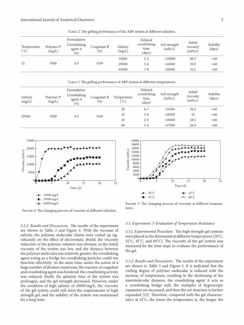
Table 2: The gelling performance of the ABP system at different salinities.
Formulation Delayedcrosslinking
time(days)
Gel strength(mPa⋅s)
Initialviscosity(mPa⋅s)
Stability(days)Temperature
(∘C)Polymer P(mg/L)
Crosslinkingagent A(%)
Coagulant B(%)
Salinity(mg/L)
32 3500 0.3 0.0915000 2-3 >20000 110.7 >6029500 5-6 >14500 33.0 >6045000 7-8 >10500 21.2 >60
Table 3: The gelling performance of ABP system at different temperatures.
Formulation Delayedcrosslinking
time(days)
Gel strength(mPa⋅s)
Initialviscosity(mPa⋅s)
Stability(days)Salinity
(mg/L)Polymer P(mg/L)
Crosslinkingagent A(%)
Coagulant B(%)
Temperature(∘C)
29500 3500 0.3 0.09
20 6-7 >11500 36.5 >6032 5-6 >14500 33 >6045 4-5 >16000 28.5 >6060 3-4 >17000 26.9 >60
0
5000
10000
15000
20000
25000
Visc
osity
(mPa
·s)
5 10 15 20 250Time (d)
15000 mg/L29500 mg/L45000 mg/L
Figure 4: The changing process of viscosity at different salinities.
3.2.2. Results and Discussions. The results of the experimentare shown in Table 2 and Figure 4. With the increase ofsalinity, the polymer molecular chains were curled up sig-nificantly on the effect of electrostatic shield; the viscosityreduction of the polymer solution was obvious, so the initialviscosity of the system was low, and the distance betweenthe polymermolecules was relatively greater; the crosslinkingagent acting as a bridge for crosslinking particles could notfunction effectively. At the same time, under the action of alarge number of divalentmetal ions, the reaction of coagulantand crosslinking agent was hindered, the crosslinking activitywas reduced, finally the gelation time of the system wasprolonged, and the gel strength decreased. However, underthe condition of high salinity of 45000mg/L, the viscosityof the gel system could still meet the requirements of highstrength gel, and the stability of the system was maintainedfor a long time.
5 10 15 20 250Time (d)
20∘C
32∘C
45∘C
60∘C
02000400060008000
100001200014000160001800020000
Visc
osity
(mPa
·s)
Figure 5: The changing process of viscosity at different tempera-tures.
3.3. Experiment 3: Evaluation of Temperature Resistance
3.3.1. Experimental Procedure. The high strength gel systemswere placed in the thermostat at different temperatures (20∘C,32∘C, 45∘C, and 60∘C). The viscosity of the gel system wasmeasured by the time steps to evaluate the performance ofthe gel.
3.3.2. Results and Discussions. The results of the experimentare shown in Table 3 and Figure 5. It is indicated that thecurling degree of polymer molecular is reduced with theincrease of temperature, resulting in the shortening of theintermolecular distance, the crosslinking agent A acts asa crosslinking bridge well, the multiples of hygroscopicexpansion are increased, and then the net structure is furtherexpanded [23]. Therefore, compared with the gel character-istics at 32∘C, the lower the temperature is, the longer the

6 International Journal of Analytical Chemistry
Table 4: The plugging rates of the ABP system in different permeability cores.
Scheme Coresnumber
Temperature(∘C)
Permeability(mD)
𝐾1
(mD)𝐾2
(mD)Plugging rate
(%)1 C1 32 300 185 0 1002 C2 32 500 291 0 1003 C3 32 1000 595 2.11 99.7
➀
➁
➂
➃
➄
➅P
P
P
➀ Electric pump➁ Thermostat➂ Intermediate container
➄ Measuring cylinder➃ Core gripper
➅ Hand pump
Figure 6: Core flow experiment device flowchart.
gelling time is and the lower the gel strength is. On thecontrary, the higher the temperature is, the shorter the gellingtime is and the greater the gel strength is.
3.4. Experiment 4: Plugging Experiment
3.4.1. Experimental Procedure
(1) The cores were evacuated and saturated with the for-mation water (salinity 29500mg/L) and then placedin the thermostat at 32∘C for 8 hours.
(2) The water flooding was carried out at the speed of0.2mL/min until the injection pressure was main-tained stably. The stable pressure difference Δ𝑃
1was
recorded, and then the permeability to water 𝐾1was
calculated.(3) The ABP system was injected into the cores at the
speed of 0.2mL/min and was left to gel for 2–4 days.(4) The following water flooding was implemented at
the speed of 0.2mL/min, and the permeability towater𝐾
2was calculated after the injection of the ABP
system. The plugging rates were calculated by (𝐾1−
𝐾2)/𝐾1×100%.The experimental flowchart is shown
in Figure 6.
3.4.2. Results and Discussions. Three cores with differentpermeability were used in the experiments, and the resultsare shown in Table 4.
As can be seen, after the ABP system is injected into coresof different permeability, good plugging effect is achieved.The plugging rate is up to 99.7% in 1000mD core and 100%plugging rate could be reached in cores of permeability300mD and 500mD.
Fluid inletFluid outlet
Number 1 Number 2 Number 3Low permeability zone
High permeability zoneNumber 6Number 4 Number 5
Figure 7: The series-parallel connection cores model sketch map.
3.5. Experiment 5: Oil Displacement Experiment
3.5.1. Experimental Procedure
(1) The parallel cores model (cores numbers 1–6) wasevacuated and saturated with the formation water(salinity 29500mg/L) and then placed in the thermo-stat maintained at 32∘C for 8 hours.
(2) The model was saturated with crude oil. The oilsaturation was calculated and then placed under thesame condition for 8 hours.
(3) Formation water was used to conduct the waterflooding experiments at the speed of 0.20mL/min.When the 70% water cut was reached in the highpermeability zone, the first plugging was carried out,and the plugging depth was equivalent to 10 cm.
(4) After the high strength gel was completely formed bytheABP system solution, theworkflowwas inserted toimplement the water flooding. When the 90% watercut was reached in the high permeability zone, thesecond plugging was carried out, and the pluggingdepth was equivalent to 20 cm.
(5) After the high strength gel was completely formed bytheABP system solution, theworkflowwas inserted toimplement the water flooding. When the 90% watercut was reached in the high permeability zone insecond time, the third plugging was carried out, andthe plugging depth was equivalent to 30 cm.
(6) After the high strength gel was completely formed bythe ABP system solution, the workflow was insertedto implement the water flooding, until the 90% watercut was reached in the high permeability zone thethird time. The amount of injection and productionwas recorded at each stage and the recovery ratewas calculated. The series-parallel connection coresmodel is shown in Figure 7.

International Journal of Analytical Chemistry 7
Table 5: The results of oil displacement experiment in different plugging depth.
Profilecontrol
Corepermeablecategory
Pluggingdepth(cm)
Permeability(mD)
Averageporosity(%)
Averagesaturation
(%)
Recoverybefore
plugging(%)
Recoveryafter plugging
(%)
EOR by gel(%)
Totalrecovery(%)
No plugging High 0 301.5 20.77 64.50 — 34.62 — 25.3Low 10.1 17.36 55.8 — 14.42 —
The firstplugging
High 10 300.8 20.45 64.55 34.62 44.3 9.68 34.39Low 10.3 17.33 55.57 14.42 22.81 8.39
The secondplugging
High 20 300.4 20.21 63.24 44.3 51.83 7.53 41.64Low 9.8 17.24 55.15 22.81 29.74 6.93
The thirdplugging
High 30 303.3 21.66 65.71 51.83 53.2 1.37 45.07Low 10.1 17.52 56.68 29.74 35.58 5.84
Recovery before pluggingEOR by gel
High Low High Low HighThe third plugging
LowThe first plugging The second plugging
0
10
20
30
40
50
60
Reco
very
(%)
Figure 8: The sketch map of EOR by the ABP high strength gel.
3.5.2. Results and Discussions. The results of the depth profilecontrol experiment of the optimized ABP high strength gelsystem are shown in Table 5 and Figure 8. In the initial waterflooding process, the injection water was mainly pushedalong the high permeability zone because the significantdifference exists between the high and low permeability zone.When the 70%water cut was reached in the high permeabilityzone, the recovery of the high and low permeability zones was34.62% and 14.42%, respectively, and the total recovery was25.30%.
The first plugging was carried out in a high permeabilityzone (core number 4), namely, 10 cm profile control depth,and then the workflow was inserted to put the water floodinginto effect. The high permeability zone (number 4) wasbypassed and the oil in low permeability zone (number 1)was displaced by the injection water. The high permeabilitycores numbers 5 and 6 were displaced by injected waterafter completely flooding core number 1; the flooding areawas enlarged, when 90% water cut was reached in the highpermeability zone; almost no liquid flowed out from the lowpermeability zone.When the profile control depth was 10 cm,the recovery of high and low permeability zones were 44.30%and 22.81%, respectively. Compared with no plugging, the
recovery of high and low permeability zone was, respectively,enhanced by 9.68% and 8.39%, and the total recovery was upto 34.39%, which was enhanced by 9.08%.
The second plugging was carried out in a high perme-ability zone, namely, 20 cm profile control depth (numbers 4and 5), and then the water flooding workflow was insertedto put the water flooding into effect. The high permeabilityzone (numbers 4 and 5) was bypassed and the oil in lowpermeability zone (numbers 1 and 2) was displaced by theinjection water. The high permeability core number 6 wasdisplaced by injected water after completely flooding coresnumbers 1 and 2. The flooding area was further enlarged.When the 90%water cut was reached in the high permeabilityzone, almost no liquid flowed out from the low permeabilityzone.When the profile control depth was 20 cm, the recoveryof the high and low permeability zones was 51.83% and29.74%, respectively. Compared with no plugging and thefirst plugging, the recovery of the high permeability zonewas, respectively, enhanced by 17.21% and 7.53%, and thatof the low permeability zone was, respectively, enhanced by15.32% and 6.93%.The total recovery was 41.64%, which was,respectively, enhanced by 16.34% and 7.25%.
In the same way, when the profile control depth wasup to 30 cm, the recovery of the high and low permeabilityzone was 53.20% and 35.58%, respectively. Compared withno plugging, the first plugging, and the second plugging,the recovery of the high permeability zone was, respectively,enhanced by 18.6%, 8.90%, and 1.37%, and the recovery of thelow permeability zone was, respectively, enhanced by 21.16%,12.77%, and 5.84%.The total recoverywas 45.07%, whichwas,respectively, enhanced by 19.77%, 10.69%, and 3.43%.
From the above analysis, it is indicated that the injectionwater flooding area is enlarged after plugging high perme-ability channels and fractures, and the recovery is enhancedsignificantly. The deeper the depth is plugged, the greater therecovery is enhanced. Except for the fact that the recoveryis enhanced in the low permeability zone, oil production isimproved continuously in the high permeability zone; that isto say that the ABP plugging fluid is of some displacementeffect on high permeability zone.The purpose of depth profilecontrol is achieved by theABP high strength gel, and a certaindisplacement effect is owned at the same time. Not only is the

8 International Journal of Analytical Chemistry
sweep extent improved in the low permeability zone, but alsothe residual oil is flooded in the high permeability zone, andthen the oil recovery is enhanced.
4. Conclusions
(1) The delayed crosslinking time decreases with theincrease of polymer concentration and the amountof crosslinking agent A. Under a certain polymerconcentration, the amount of crosslinking agent Aand coagulant B should be suitable so that the phe-nomenon of excessive crosslinking is avoided. Fromthe point of delayed crosslinking time, the amount ofcrosslinking agent should be used less. The coagulantB should not be used excessively, and the reasonableproportion of the crosslinking agent and coagulantshould be more than 3 : 1.
(2) The greater the initial viscosity of the system is, thebetter the effect on gelling is. The high strength gel isapplied to plug big channels and fractures. The initialviscosity is about 30mPa⋅s, which is easily injectedin early stages and then in favor of forming highstrength gel (>10000mPa⋅s). Under the conditionsof 29500mg/L salinity water and 32∘C, consideringthe gel strength, delayed crosslinking time, stabil-ity, and other factors, the optimized formulation is0.3% crosslinking agent A + 0.09% coagulation B+ 3500mg/L polymer solution P. In the process ofpractical application, formulations should be appro-priately selected according to the salinity conditions.
(3) With the increase of salinity, under the action ofthe electrostatic shield and a large number of diva-lent metal ions, the polymer molecular chains werecurled up seriously, and the reaction of coagulant andcrosslinking agent was hindered. The crosslinkingactivity was reduced. Finally the gelation time of thesystemwas prolonged, and the gel strength decreased.
(4) The curling degree of polymer molecular is reducedwith the increase of temperature, resulting in the factthat the intermolecular distance is relatively short-ened. The crosslinking agent A acts as a crosslinkingbridge as well. The multiples of hygroscopic expan-sion are increased, and then the net structure is fur-ther expanded. Compared with the gel characteristicsat 32∘C, the lower the temperature is, the longer thegelling time is and the lower the gel strength is. On thecontrary, the higher the temperature is, the shorter thegelling time is and the greater the gel strength is.
(5) The purpose of depth profile control is achievedby the ABP high strength gel, and the recovery isenhanced greatly with the plugging depth increasing.A certain displacement effect is owned at the sametime. Not only is the sweep extent improved in thelow permeability zone, but also the residual oil isflooded in the high permeability zone, and then theoil recovery is enhanced.
Conflicts of Interest
The authors declare that there are no conflicts of interestregarding the publication of this paper.
Acknowledgments
This work is financially supported by the National NaturalScience Foundation of China under Grant no. 51504069.
References
[1] H. Xiong and S. A. Holditch, “Will the blossom of unconven-tional natural gas development in north america be repeated inchina?” Society of Petroleum Engineers, 2006.
[2] E.Delamaide, R. Tabary, andD. Rousseau, “Chemical Eor in lowpermeability reservoirs,” Society of Petroleum Engineers, 2014.
[3] Z. Lei, B. Gong, F. Wang, T. Wang, and Q. Li, “A dynamic dis-crete fracturemodel for fluid flow in fractured low-permeabilityreservoirs,” Society of Petroleum Engineers, 2015.
[4] D. F. Wang, Ordos Basin Extra-Low Permeability Oilfield Devel-opment, Petroleum Industry Press, Beijing, China, 2007.
[5] P. L. Zitha and M. Darwish, “Effect of bridging adsorption onthe placement of gels for water control,” in Proceeding of the SPEAsia Pacific ImprovedOil Recovery Conference, SPE 57269, KualaLumpur, Malaysia, October 1999.
[6] F. B. Thomas, D. B. Bennion, G. E. Anderson, B. T. Meldrum,and W. J. Heaven, “Water shut-off treatments reduce waterand accelerate oil production,” Journal of Canadian PetroleumTechnology, vol. 39, no. 4, pp. 25–29, 2000.
[7] G. A. Al-Muntasheri and P. L. Zitha, “Gel under dynamic stressin porous media: new insights using computed tomography,”in Proceeding of the SPE Saudi Arabia Section Technical Sympo-sium, PaperSPE 126068, Al-Khobar, Saudi Arabia, May 2009.
[8] Y. Wu, T. Tang, B. Bai, X. Tang, J. Wang, and Y. Liu, “An exper-imental study of interaction between surfactant and particlehydrogels,” Polymer, vol. 52, no. 2, pp. 452–460, 2011.
[9] R. Ortiz, R. R. Monroy, N. Toledo, and etal., “Field applicationsof low molecular-weight polymer activated with an organiccrosslinker for water conformance in south mexico,” in Pro-ceeding of the SPE Annual Technical Conference and Exhibition,Houston, Tex, USA, September 2004.
[10] J. Vasquez, D. Dalrymple, L. Eoff, and B. R. Reddy, “Develop-ment and evaluation of high-temperature conformance poly-mer systems,” in Proceeding of the SPE International Symposiumon Oilfield Chemistry, The Woodlands, Tex, USA, February2005.
[11] R. Hernandez, J. Vasquez, V. Cancino, and E. Soriano, “Suc-cessful water-shutoff case histories in a naturally fracturedcarbonate reservoir in offshore Mexico using an organicallycrosslinked polymer system with a modified tail-in,” in Pro-ceeding of the SPE International Symposium and Exhibiton onFormation Damage Control, Lafayette, La, USA, February, 2010.
[12] S. Uddin, J. D. Dolan, R. A. Chona et al., “Lessons learned fromthe first openhole horizontal well water shutoff job using twonew polymer systems—a case history from wafra ratawi field,kuwait,” in Proceedings of the 13th SPEMiddle East Oil Show andConference (MEOS ’03), Paper SPE 127981, Bahrain, April 2003.
[13] J. Vasquez and L. Eoff, “LaboratoryDevelopment and SuccessfulField Application of a Conformance Polymer System for Low-,Medium-, and High-Temperature Applications,” in Proceeding

International Journal of Analytical Chemistry 9
of the SPE Latin American andCaribbean PetroleumEngineeringConference, Paper SPE 139308, Lima, Peru, December 2010.
[14] T. Bach, K. E. Wennberg, A. Mebratu, W. P. Hendriks, J. M.Warren Jr., and T. Rolfsvaag, “Polymer sealant for unwanted gasin openhole gravel-pack completion,” in Proceeding of the SPEEuropean Formation Damage Conference, Paper SPE 68975,TheHague, Netherlands, May 2001.
[15] A. Mebratu, B. Nerland, and T. Kleppan, “Annular barrier re-establishment using a long-life, high-strength polymer gelsystem,” in procceding of the SPE international Symposium andExhibition on Formation Damage Control, Paper SPE 86547,Lafayette, La, USA, February 2004.
[16] R. S. Seright and F. D. Martin, “Impact of Gelation pH, RockPermeability, and Lithology on the Performance of aMonomer-Based Gel”.
[17] J. Hailong, Low-toxicity weak gel profile-modifying enhanced oilrecovery technology research, Southwest Petroleum University,2016.
[18] L. Yongtai, The Weak Gel Flooding Technology Research, D.Shanghai Institute ofMetallurgy, Chinese Academy of Sciences,2000.
[19] B. R. R. Reddy, F. Crespo, and L. S. Eoff, “Water Shutoff atUltralow Temperatures UsingOrganically Crosslinked PolymerGels,” in SPE Improved Oil Recovery Symposium, Society ofPetroleum Engineers, January 2012.
[20] Y.-Q. Li, T.-J. Wei, and G.-C. Jing, “Experimental study onsealing fractured sandstone using SMA hard-gel,” Journal ofXi’an Shiyou University (Natural Science Edition), vol. 21, no. 4,pp. 61–64, 2006.
[21] C. Dinglin,Research onHigh Strength Composite Gel System andits Sealing Performance, D. Xi’an Petroleum University, 2014.
[22] Z. Jisheng, The Study on the Chain Structure and Oil RecoveryMechanism of Partially Hydrolyzed Polyacrylamide, D. JilinUniversity, 2004.
[23] W. Xiaoyan, The Polymer Molecular Configuration of Oil Dis-placement Agents and Their Flow Characteristics, D. DaqingPetroleum Institute, 2010.

Submit your manuscripts athttps://www.hindawi.com
Hindawi Publishing Corporationhttp://www.hindawi.com Volume 2014
Inorganic ChemistryInternational Journal of
Hindawi Publishing Corporation http://www.hindawi.com Volume 201
International Journal ofInternational Journal ofPhotoenergy
Hindawi Publishing Corporationhttp://www.hindawi.com Volume 2014
Carbohydrate Chemistry
International Journal ofInternational Journal of
Hindawi Publishing Corporationhttp://www.hindawi.com Volume 2014
Journal of
Chemistry
Hindawi Publishing Corporationhttp://www.hindawi.com Volume 2014
Advances in
Physical Chemistry
Hindawi Publishing Corporationhttp://www.hindawi.com
Analytical Methods in Chemistry
Journal of
Volume 2014
Bioinorganic Chemistry and ApplicationsHindawi Publishing Corporationhttp://www.hindawi.com Volume 2014
SpectroscopyInternational Journal of
Hindawi Publishing Corporationhttp://www.hindawi.com Volume 2014
The Scientific World JournalHindawi Publishing Corporation http://www.hindawi.com Volume 2014
Medicinal ChemistryInternational Journal of
Hindawi Publishing Corporationhttp://www.hindawi.com Volume 2014
Chromatography Research International
Hindawi Publishing Corporationhttp://www.hindawi.com Volume 2014
Applied ChemistryJournal of
Hindawi Publishing Corporationhttp://www.hindawi.com Volume 2014
Hindawi Publishing Corporationhttp://www.hindawi.com Volume 2014
Theoretical ChemistryJournal of
Hindawi Publishing Corporationhttp://www.hindawi.com Volume 2014
Journal of
Spectroscopy
Analytical ChemistryInternational Journal of
Hindawi Publishing Corporationhttp://www.hindawi.com Volume 2014
Journal of
Hindawi Publishing Corporationhttp://www.hindawi.com Volume 2014
Quantum Chemistry
Hindawi Publishing Corporationhttp://www.hindawi.com Volume 2014
Organic Chemistry International
ElectrochemistryInternational Journal of
Hindawi Publishing Corporation http://www.hindawi.com Volume 2014
Hindawi Publishing Corporationhttp://www.hindawi.com Volume 2014
CatalystsJournal of