forming simulation for fiber reinforced thermoplastic with
TRANSCRIPT

15th International LS-DYNA® Users Conference Composites
June 10-12, 2018 1
Forming Simulation for Fiber Reinforced Thermoplastic
with Introduction to J-Composites
Masato Nishi, Sean Wang, Shaun Dougherty JSOL Corporation
Harumi Center Bldg. 2-5-24 Harumi, Chuo-ku, Tokyo, 104-0053, Japan
Abstract Fiber reinforced composites are good alternatives for metals used in load transmission structures. The increasing requirement for high performance and weight reduction in industry has gradually expanded the use of composites. Finite element analysis as an alternative approach to experimental study is effective in designing fiber reinforced composite products because there are many design parameters. Process/process-chain simulations are especially important because the performance of the final composite part strongly depends on changes in fiber orientation during the process. In this context, we are developing the J-Composites series. A series of new software tools to help our LS-DYNA® users easily conduct process/process-chain simulations of fiber reinforced composites. This paper introduces the first software tool, which is called J-Composites/Form Modeler. This tool is for creating FE models for continuous fiber reinforced composite forming simulation. Users can create models that, when used with LS-DYNA, will accurately predict the macroscopic forming behavior of laminate plies made of dry fabric and thermoplastic/thermoset pre-pregs. Through simulation, this tool can help the user detect forming defects like wrinkling, fiber bridging and rupture, which leads to reduced development time and cost. We will introduce the key features of Form Modeler, such as easy build-up of material models with automatic parameter identification based on material testing results, efficient setup of laminate modeling with the easy-to-use UI, and the mapping of forming information to crash simulation models. In addition, a case study of thermoplastic pre-preg forming with LS-DYNA will be shown. Finally, our development plans for Form Modeler Ver. 2.0 and other tools as part of the J-Composites series will be introduced.
1. Introduction
The increasing requirement for crash safety with weight reduction in the automotive industry has gradually expanded the use of carbon fiber reinforced plastic (CFRP). One of the reasons for the expansion is that the development of various manufacturing processes has reduced the cycle time needed in order to be applied to the mass production of car. Finite element (FE) simulation is effective in optimizing process conditions, and minimizing lead times and design costs. When the length of reinforced fiber is short, the fiber reinforced composites are produced by injection molding.
Three-dimensional and complicated components can be easily molded, while local fiber orientation caused by the injection molding process results in strong anisotropy in the material properties of the component. It is known that the process has a large influence on the evaluation of product performance. By linking LS-DYNA with Moldex3D® (commercial injection molding simulation software) [1] and Digimat® (material characteristic prediction software) [2], it is possible to predict product performance that considers the effects of the injection molding process. Moldex3D can predict fiber behavior, such as the fiber orientation that gets generated during the process. Also, Digimat can predict the local nonlinear material properties. Since the reinforcing effect is small in injection molding using short fibers, product development by
compression molding, which reinforces with fibers several tens of mm in length, has been actively carried out recently. In the literature [3], it was reported that it is generally challenging for commercial injection molding software, such as Moldex3D, to predict material behavior correctly during the compression molding process. Also, with one-way material flow and the fiber orientation coupling scheme, it is very difficult for Moldex3D to
Copyr
ight
by
DYNAm
ore

15th International LS-DYNA® Users Conference Composites
June 10-12, 2018 2
handle cases with high fiber volume contents and long reinforcing fibers. The reason is an anisotropic flow can also occur due to the interaction between fibers. To overcome these problems, a new simulation technology for compression molding of long fiber reinforced plastics was implemented and has been enhanced in LS-DYNA [4]. The main features of this new technology are fibers modelled by beam elements and matrices modelled by tetrahedron solid elements with an r-adaptive remeshing function based on an Element-Free-Galerkin (EFG) formulation. Relative motion of beams in the solid elements is simulated by coupling momentum along the normal direction of each beam element. This coupling method transfers load from beam to solid and viceversa, a so-called strong coupling interaction. Solid elements for the matrix are adequately remeshed with an r-adaptive function which enables large deformations and can generate complex shapes. In order to make the most of the excellent mechanical properties of the fiber, reinforcing by continuous fiber is
most effective. This fact led to manufacturing processes such as resin transfer molding (RTM) and resin pre-impregnated sheet forming being developed. The dominant deformation modes of dry fabric and thermoplastic/thermoset pre-preg materials during the forming process are in-plane shear and out-of-plane bending due to high deformability. In particular, bending behavior affects the onset and formation of wrinkles, which is one of the major forming defects. Therefore accurate description of bending behavior is an important aspect in the accurate prediction of wrinkles. To simulate bending behavior accurately, some FE models proposed in recent studies capture bending stiffness as a bending virtual work separately from in-plane deformation [5, 6]. The shell-membrane model proposed in the author’s previous study also deals with bending stiffness as a function of the rotation of the mid-surface [7, 8]. Furthermore, the influence of transverse shear deformation upon bending behavior, especially small wrinkling, was numerically examined [9].
Figure 1: Overview of composite process and process-chain simulations with J-Composites.
Because LS-DYNA can take into account large deformation and multi-physics, etc., it is possible to accurately simulate complicated behavior of composite materials during the manufacturing process, as mentioned above.
LS-DYNA
Digi
mat
Moldex3D
LS-DYNA
Moldex3D
Process / Process chainsimulationsFRP composites
Injectionmolding
Compressionmolding
Pre-pregforming
Shor
t fib
er-2
mm
Long
fibe
r10
-50m
mCo
ntin
uous
fibe
rU
D, W
oven
RTMpreform molding
Structure / CrashsimulationsProcess
Copyr
ight
by
DYNAm
ore

15th International LS-DYNA® Users Conference Composites
June 10-12, 2018 3
However, it is difficult for users to easily apply to the design and development stage since it requires much effort to understand the complicated modeling. In order to support the design and utilization of composite manufacturing process and process chain simulations, JSOL has promoted the development of the J-Composites [10] as a modeling tool series as shown in Figure 1, and released the series’ first tool, Form Modeler, for continues fiber reinforced composite forming analysis. In this paper, we will introduce the key features of Form Modeler, such as easy build-up of material models
with automatic parameter identification based on material testing results, efficient setup of laminate modeling with the easy-to-use UI, and the mapping of forming information to crash simulation models. In addition, a case study of thermoplastic pre-preg forming with LS-DYNA will be shown. Finally, our development plans for Form Modeler Ver. 2.0 and other tools as part of the J-Composites series will be introduced.
2. Introducing J-Composites/Form Modeler
J-Composites/Form Modeler is a tool for creating composite forming simulation models. There are three
modules, Material DB, Lay-up Modeler and Layup Mapper, so that users can easily create LS-DYNA models that will accurately predict the behavior of dry fabric and thermoplastic/thermoset pre-preg sheets during forming and conduct process-chain simulations. 2.1. Material DB Using the Material DB, it is possible to automatically construct material models for forming simulation from
the measurement results of various material properties, such as tension and bending properties of dry fabric and pre-pregs, registered in the database. A standard material database, containing several materials such as Toreca® and TEPEX®, is also provided as show in Figure 2.
Figure 2: Standard material database on Form Modeler, such as Toreca® and TEPEX®.
Table 1: Supported material modelling types in Material DB.
Material modelling pattern Modelling technique In-plane MAT type
Out-of-plane MAT type
1
Shell-membrane model
MAT_034 MAT_002 2 MAT_034 MAT_249 3 MAT_249 MAT_002 4 MAT_249 MAT_249
5 Reissner-Mindlin shell model MAT_249
You can choose from two material modelling types in Material DB. One is shell-membrane model which
assums that the out-of-plane moment is decoupled from the in-plane stress. The other is Reissner-Mindlin shell model which can simulate transverse shear deformation. As shown in Table 1, the shell-membrane model supports separate MAT types for the membrane elements and shell elements, and Reissner-Mindlin shell model only supports MAT_249, so far. Supported MAT types may be added in the future.
Copyr
ight
by
DYNAm
ore

15th International LS-DYNA® Users Conference Composites
June 10-12, 2018 4
2.2. Lay-up Modeler With the Lay-up Modeler, users can easily set up complex laminate patterns in one step, and export the model
as an LS-DYNA input file. In the Lay-up Modeler, a template model is used along with plies and contact information to create a composite model for forming simulation. There are two different laminate modelling types here. One is multiple PARTs which can simulate the slippage
between the neighboring plies. The other is the single PART_COMPOSITE which is not able to consider the slippage between plies, but the computational cost is much less than modelling with multiple PARTs. The multiple PARTs type can mix shell-membrane models and Reissner-Mindlin shell models, but the single PART_COMPOSITE type can only use Reissner-Mindlin shell models.
Selection of laminate modelling type and set up complex laminate patterns in one step
Multiple PARTs: a *PART is created for each ply and *CONTACTs are created
Single PART_COMPOSITE: a single shell is created and integration point data is set for each ply
Figure 3: Laminate modeling and set-up laminate pattern.
2.3. Lay-up Mapper By mapping fiber direction from a forming analysis result to its structural analysis mesh, it is possible to
evaluate and analyze structural and crash performance that takes into account local changes in fiber direction that occur during forming. Using the Lay-up Mapper, it is possible to map fiber direction (beta) data from the specified parts of a source model, usually a forming result (dynain) to the specified parts of a target model,
Copyr
ight
by
DYNAm
ore

15th International LS-DYNA® Users Conference Composites
June 10-12, 2018 5
usually a structural or crash simulation model. Table 2 shows the possible layer methods for the source model and target model.
Table 2: Supported laminate modelling typse in Lay-up Mapper.
Laminate modelling type Description Source model Target model
Multiple PARTs Layers made up of *PART and *ELEMENT_SHELL, different *PART per layer
✔ ✔
Single PART_COMPOSITE Layers made up of *PART_COMPOSITE and *ELEMENT_SHELL or *PART and *ELEMENT_SHELL_COMPOSITE
✔ ✔
Solid PARTs Layers made up of *PART and *ELEMENT_SOLID, different *PART per layer
✔
3. Case Study: Material Characterization of Thermoplastic Pre-preg
In this section, the identification processes for material parameters with J-Composites/Form Modeler will be
discussed. Tepex® dynalite 102-RG600, which consists of a polyamide 6 (PA6) thermoplastic matrix and twill woven glass fiber fabric, was used in this study. 3.1. Thermo-mechanical properties Each mechanical parameter in each model was identified through a series of coupon tests at high temperatures,
uniaxial tension across yarn direction, bias-extension and 3-point bending across yarn direction and in 45˚ direction. In uniaxial tension and bias-extension, the thermal conditions were realized with a special heating unit and a hot air gun. With this configuration, testing without slipping could be realized because the specimens were heated only at the center and not in the sections of the jaws, as shown in Figure 4 (left). 3-point bending was conducted within a temperature chamber. The thermo-mechanical characterization was conducted at Fraunhofer EMI in Germany.
Figure 4: Setups for uniaxial tension and bias extension (left) and 3-point bending (right) at high temperatures.
As mentioned in the last section, we can choose from two different material modelling techniques and three
MAT types in Form Modeler. This case study used the recommended shell-membrane model with MAT_249 both for in-plane and out-of-plane. The results of the coupon experiments were imported into Material DB to automatically create the material model for composite forming simulation as shown in Figure 5
Copyr
ight
by
DYNAm
ore

15th International LS-DYNA® Users Conference Composites
June 10-12, 2018 6
Figure 5: UI to import coupon experimental results in Form Modeler.
3.2. Thermo-physical properties The thermo-physical characterization was conducted at Fraunhofer IWM in Germany. In order to characterize
the thermo-physical properties of two types of thermoplastic pre-pregs, the following measurements were performed: ・ Measurement of specific heat capacity, Cp(T), using DSC (Differential Scanning Calorimetry) ・ Measurement of linear thermal expansion coefficient using TMA (Thermo-mechanical Analysis /
Dilatometry) and temperature-dependent density change, ρ(T). ・ Measurement of thermal diffusivity, a(T), using LFA (Laser Flash Analysis), and heat conductivity,
λ(T), determined by following equation: 𝜆𝜆(𝑇𝑇) = 𝑎𝑎(𝑇𝑇) ∙ 𝐶𝐶𝐶𝐶(𝑇𝑇) ∙ 𝜌𝜌(𝑇𝑇) (1)
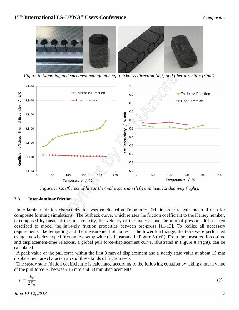
Composite materials were characterized by their anisotropic properties, thus a scheme was devised in order to measure direction-dependent thermos-physical properties during sampling and specimen manufacturing. Firstly, consolidated laminate sheets were produced by HTP (High Temperature and Pressure) process. Then a waterjet was used to cut the sheets in in-plane and out-plane directions, to secure specimens for thickness and fiber direction respectively, as shown in Figure 6. Thermal expansion, for the reason that the material can expand freely in the thickness direction, while it is
restricted in fiber direction (due to the woven structure), the thermal expansion in fiber direction is much smaller than in thickness direction as shown in Figure 7( left). Regarding heat conductivity, because of the poor conductivity of glass fiber itself, it shows only a slight difference between thickness and fiber direction, as shown in Figure 7 (right).
Copyr
ight
by
DYNAm
ore
15th International LS-DYNA® Users Conference Composites
June 10-12, 2018 7
Figure 6: Sampling and specimen manufacturing: thickness direction (left) and fiber direction (right).
Figure 7: Coefficient of linear thermal expansion (left) and heat conductivity (right).
3.3. Inter-laminar friction Inter-laminar friction characterization was conducted at Fraunhofer EMI in order to gain material data for
composite forming simulations. The Stribeck curve, which relates the friction coefficient to the Hersey number, is composed by mean of the pull velocity, the velocity of the material and the normal pressure. It has been described to model the intra-ply friction properties between pre-pregs [11-13]. To realize all necessary requirements like tempering and the measurement of forces in the lower load range, the tests were performed using a newly developed friction test setup which is illustrated in Figure 8 (left). From the measured force-time and displacement-time relations, a global pull force-displacement curve, illustrated in Figure 8 (right), can be calculated. A peak value of the pull force within the first 3 mm of displacement and a steady state value at about 15 mm
displacement are characteristics of these kinds of friction tests. The steady state friction coefficient 𝜇𝜇 is calculated according to the following equation by taking a mean value
of the pull force FP between 15 mm and 30 mm displacements:
𝜇𝜇 =𝐹𝐹𝑝𝑝
2𝐹𝐹𝑁𝑁 (2)
-1.E-04
0.E+00
1.E-04
2.E-04
3.E-04
4.E-04
5.E-04
0 50 100 150 200 250
Coef
ficie
nt o
f lLi
near
The
rmal
Exp
ansi
on
/ 1
/K
Temperature / °C
Thickness Direction
Fiber Direction
0.0
0.1
0.2
0.3
0.4
0.5
0.6
0.7
0.8
0.9
1.0
0 50 100 150 200 250
Heat
Con
duct
ivity
/
W/m
K
Temperature / °C
Thickness Direction
Fiber Direction
Copyr
ight
by
DYNAm
ore

15th International LS-DYNA® Users Conference Composites
June 10-12, 2018 8
By taking viscosity 𝜂𝜂 of PA6, pull velocity vP and normal pressure 𝜎𝜎𝑁𝑁, a Stribeck curve can be generated, which relates the steady state friction coefficient 𝜇𝜇 to the Hersey number He. The Hersey number is calculated according to the following equation:
𝐻𝐻𝐻𝐻 =𝜂𝜂𝑣𝑣𝑝𝑝𝜎𝜎𝑁𝑁
(3)
Figure 8: Testing facility (left) and representative force-displacement curve progression (right).
With respect to the generation of the Stribeck curves friction tests with varying pull velocities (0.1 / 1 / 10
mm/s), temperatures (230 / 250 °C) and normal pressures (0.01 / 0.1 MPa) were carried out. Based on the test data, it is possible to analyze the dependencies on pull velocity, temperature, and normal pressure. The Stribeck curve, illustrated in Figure 9, summarizes the steady state friction coefficients of all test conditions. The error bars indicate the standard deviation of three test replications. The results of all different measurements do reproduce very well and follow a clear global trend.
Figure 9: Stribeck curve (left) and UI to define the inter-laminar friction in Form Modeler (right).
Stribeck curve Viscosity vs. TemperatureCopyr
ight
by
DYNAm
ore

15th International LS-DYNA® Users Conference Composites
June 10-12, 2018 9
4. Case Study: Forming Simulation of Thermoplastic Pre-preg
Automotive B-pillar forming simulation for simple laminates with [(0/90)]4 and [(45/-45)]4 lay-ups are by
using the identified parameters with J-Composites/Form Modeler. A schematic figure of the FE model is shown in Figure 10. The laminate is modeled as multiple PARTs, in which each ply consists of a shell-membrane model, and *CONTACT_AUTOMATIC_ONE_WAY_SURFACE_TO_SURFACE_COMPOSITEs are created to consider the slippage between the neighboring layers. The total number of elements to model the laminate sums up to 322,500 over four plies. The die and punch are modeled as rigid bodies.
Figure 10: Automotive B-pillar forming simulation model of pre-consolidated laminate.
Figure 11: Comparison of deformation of automotive B-pillar of [(0/90)]4 and [(45/-45)]4 lay-ups.
Before the non-isothermal forming simulation, an isothermal self-gravity simulation of the heated laminate at
250°C is performed by mechanical analysis. After the self-gravity simulation, the non-isothermal forming
Punch
Die
Blank with 4plyshell
shell
membrane
Each ply consists ofshell-membrane model.
Copyr
ight
by
DYNAm
ore
15th International LS-DYNA® Users Conference Composites
June 10-12, 2018 10
simulation is conducted by thermal-mechanical coupling analysis. The initial temperatures of the laminate and tools in the non-isothermal forming simulation are set at 250°C and 25°C respectively. Figure 11 shows the comparison of the deformation after forming of the automotive B-pillar of [(0/90)]4 and [(45/-45)]4 lay-ups.
5. Future Development Plan
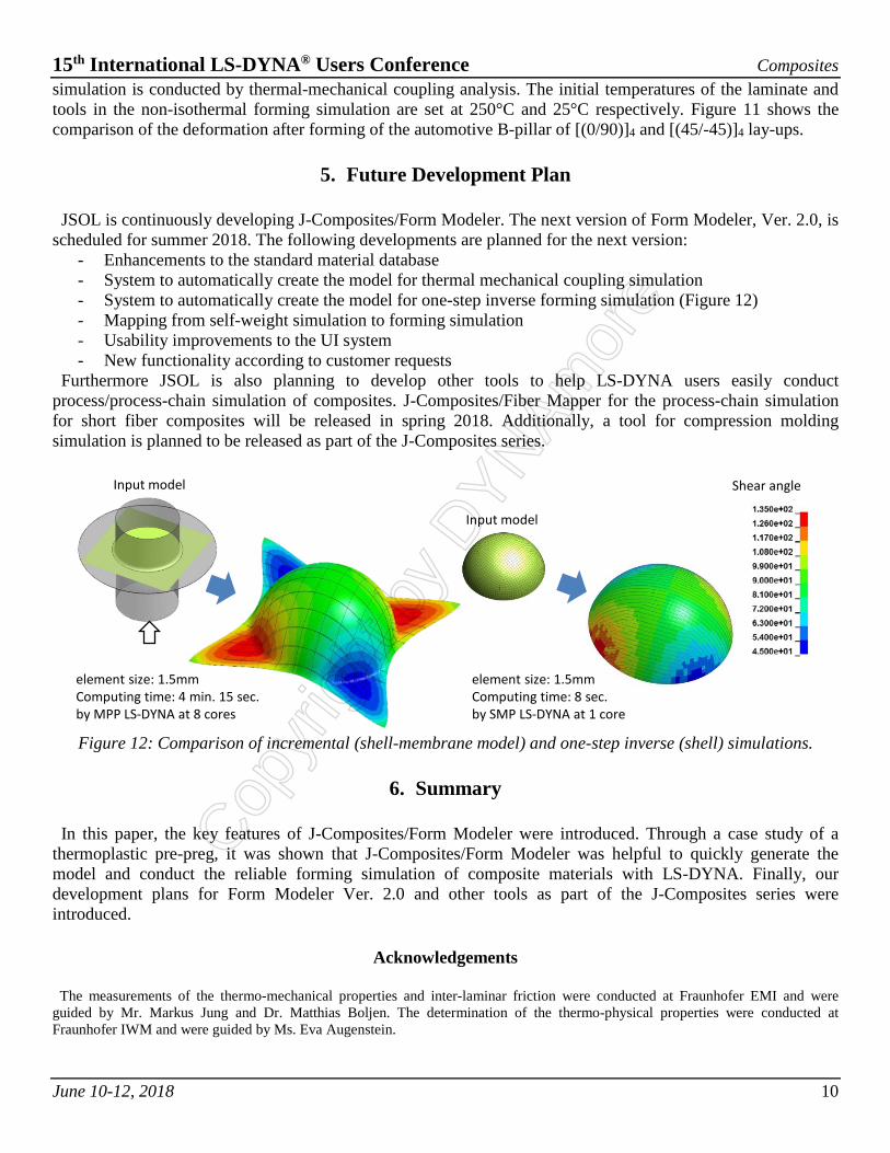
JSOL is continuously developing J-Composites/Form Modeler. The next version of Form Modeler, Ver. 2.0, is
scheduled for summer 2018. The following developments are planned for the next version: - Enhancements to the standard material database - System to automatically create the model for thermal mechanical coupling simulation - System to automatically create the model for one-step inverse forming simulation (Figure 12) - Mapping from self-weight simulation to forming simulation - Usability improvements to the UI system - New functionality according to customer requests
Furthermore JSOL is also planning to develop other tools to help LS-DYNA users easily conduct process/process-chain simulation of composites. J-Composites/Fiber Mapper for the process-chain simulation for short fiber composites will be released in spring 2018. Additionally, a tool for compression molding simulation is planned to be released as part of the J-Composites series.
Figure 12: Comparison of incremental (shell-membrane model) and one-step inverse (shell) simulations.
6. Summary
In this paper, the key features of J-Composites/Form Modeler were introduced. Through a case study of a
thermoplastic pre-preg, it was shown that J-Composites/Form Modeler was helpful to quickly generate the model and conduct the reliable forming simulation of composite materials with LS-DYNA. Finally, our development plans for Form Modeler Ver. 2.0 and other tools as part of the J-Composites series were introduced.
Acknowledgements
The measurements of the thermo-mechanical properties and inter-laminar friction were conducted at Fraunhofer EMI and were
guided by Mr. Markus Jung and Dr. Matthias Boljen. The determination of the thermo-physical properties were conducted at Fraunhofer IWM and were guided by Ms. Eva Augenstein.
element size: 1.5mmComputing time: 4 min. 15 sec.by MPP LS-DYNA at 8 cores
Shear angleInput model
Input model
element size: 1.5mmComputing time: 8 sec.by SMP LS-DYNA at 1 core
Copyr
ight
by
DYNAm
ore
15th International LS-DYNA® Users Conference Composites
June 10-12, 2018 11
References
[1] Moldex3D, http://cae.jsol.co.jp/moldex3d/ [2] Digimat, http://cae.jsol.co.jp/digimat/ [3] V. Romanenko et al., Development of Advanced 3D Process Simulation for Carbon Fiber Sheet Molding Compounds in
Automotive Series Applications, 17th European Conference on Composite Materials, (2016). [4] S. Hayashi et al., Development of New Simulation Technology for Compression Molding of Long Fiber Reinforced Plastics,
21st International Conference on Composite Materials, (2017). [5] P. Boisse et al., Simulation of Wrinkling during Textile Composite Reinforcement Forming. Influence of Tensile, In-plane Shear
and Bending Stiffnesses, Composites Science and Technology, vol.71, pp.683–692, (2011). [6] S.P. Haanappel et al., Formability Analyses of Uni-Directional and Textile Reinforced Thermoplastics, Composites Part A:
Applied Science and Manufacturing, vol.56, pp.80-92, (2014). [7] M. Nishi et al., Textile composite reinforcement forming analysis considering out-of-plane bending stiffness and tension
dependent in-plane shear behavior, 16th European Conference on Composite Materials, (2014). [8] M. Nishi et al., Thermoforming Simulation of Thermoplastic Pre-Impregnated Textile Reinforcement, 20th International
Conference on Composite Materials, (2015). [9] M. Nishi et al., Constitutive Modeling Of Carbon Fiber Fabric: From Material Parameter Identification To Application In Fe
Forming Simulation, 17th European Conference on Composite Materials, (2016). [10] J-Composites, https://cae.jsol.co.jp/jcomposites/ [11] Y.R. Larberg et al., On the interply friction of different generations of carbon/epoxy prepreg systems, Composites Part A, vol.42,
pp.1067-1074, (2011). [12] Q. Chen et al., Intra/inter-ply shear behaviors of continuous fiber reinforced thermoplastic composites in thermoforming
processes, Composite Structures, vol.93, pp.1692-1703, (2011). [13] P. Wang, et al., Thermoforming simulation of multilayer composites with continuous fibres and thermoplastic matrix,
Composites Part B, vol.52, pp.127–136, (2013).
Copyr
ight
by
DYNAm
ore