formally designing and implementing cyber security
TRANSCRIPT

University of LouisvilleThinkIR: The University of Louisville's Institutional Repository
Electronic Theses and Dissertations
8-2019
Formally designing and implementing cybersecurity mechanisms in industrial control networks.Mehdi SabraouiUniversity of Louisville
Follow this and additional works at: https://ir.library.louisville.edu/etdPart of the Computer and Systems Architecture Commons, Controls and Control Theory
Commons, Information Security Commons, OS and Networks Commons, Other ComputerEngineering Commons, Software Engineering Commons, Systems Architecture Commons, and theTheory and Algorithms Commons
This Doctoral Dissertation is brought to you for free and open access by ThinkIR: The University of Louisville's Institutional Repository. It has beenaccepted for inclusion in Electronic Theses and Dissertations by an authorized administrator of ThinkIR: The University of Louisville's InstitutionalRepository. This title appears here courtesy of the author, who has retained all other copyrights. For more information, please [email protected].
Recommended CitationSabraoui, Mehdi, "Formally designing and implementing cyber security mechanisms in industrial control networks." (2019). ElectronicTheses and Dissertations. Paper 3271.https://doi.org/10.18297/etd/3271

FORMALLY DESIGNING AND IMPLEMENTING CYBER SECURITY
MECHANISMS IN INDUSTRIAL CONTROL NETWORKS
BY
Mehdi Sabraoui
B.S., University of Louisville, 2013
M.Eng., University of Louisville, 2014
A Dissertation
Submitted to the Faculty of the
J. B. Speed School of Engineering
in Partial Fulfillment of the Requirements
for the Degree of
Doctor of Philosophy
in Computer Science and Engineering
Department of Computer Science and Engineering
J.B Speed School of Engineering
University of Louisville
Louisville, Kentucky
August 2019


ii
FORMALLY DESIGNING AND IMPLEMENTING CYBER SECURITY
MECHANISMS IN INDUSTRIAL CONTROL NETWORKS
BY
Mehdi Sabraoui
B.S., University of Louisville, 2013
M.Eng., University of Louisville, 2014
A Dissertation Approved on
July 23, 2019
By the following Dissertation Committee members
________________________________________
Dr. Adrian P. Lauf, Dissertation Director
________________________________________
Dr. Jeffrey L. Hieb, Dissertation Co-Director
________________________________________
Dr. Roman V. Yampolskiy
________________________________________
Dr. Michael Losavio
________________________________________
Dr. Adel Elmaghraby

iii
DEDICATION
This dissertation is dedicated to my parents
Rebecca Sabraoui and Ben Sabraoui
whose hard work and constant support have granted me this privilege.

iv
ACKNOWLEDGEMENTS
I cannot understate how much the support of my advisors, Dr. Jeff Hieb and Dr.
Adrian Lauf, have helped me through the academic, professional, and emotional ups and
downs of this journey. I would also like to extend my deepest gratitude to Dr. Adel
Elmaghraby for his clever administrative support for me and all the students in the
department who come to him for help and guidance. I am grateful to the rest of my
committee members, Dr. Roman Yampolskiy and Dr. Michael Losavio, for their
invaluable insights and friendly conversations through the tough times. Finally, I want to
recognize all the friends and family who have been patient and understanding with my
occasional absences through the past few years.

v
ABSTRACT
FORMALLY DESIGNING AND IMPLEMENTING CYBER SECURITY
MECHANISMS IN INDUSTRIAL CONTROL NETWORKS
Mehdi Sabraoui
July 23, 2019
This dissertation describes progress in the state-of-the-art for developing and
deploying formally verified cyber-resilient devices in industrial control networks. It
begins by detailing the unique struggles that are faced in industrial control networks and
why concepts and technologies developed for securing traditional networks might not be
appropriate. It uses these unique struggles and examples of contemporary cyber-attacks
targeting control systems to argue that progress in securing control systems is best met
with formal verification of systems, their specifications, and their security properties.
This dissertation then presents a development process and identifies two technologies,
TLA+ and seL4, that can be leveraged to produce a high-assurance embedded security
device.
The method presented in this dissertation takes an informal design of an
embedded device that might be found in a control system and 1) formalizes the design
within TLA+, 2) creates and mechanically checks a model built from the formal design,
and 3) translates the TLA+ design into a component-based architecture of a native seL4

vi
application. The later chapters of this dissertation describe an application of the process
to a security preprocessor embedded device that was designed to add security
mechanisms to the network communication of an existing control system. The device and
its security properties are formally specified in TLA+ in chapter 4, mechanically checked
in chapter 5, and finally its native seL4 architecture is implemented in chapter 6. Finally,
the conclusions derived from the research are laid out, as well as some possibilities for
expanding the presented method in the future.

vii
TABLE OF CONTENTS
PAGE
DEDICATION .................................................................................................................. iii ACKNOWLEDGEMENTS .............................................................................................. iv
ABSTRACT ........................................................................................................................ v
LIST OF TABLES ........................................................................................................... xii LIST OF FIGURES ....................................................................................................... xiv
CHAPTER I INTRODUCTION ........................................................................................ 1
1.1 Industrial Control Systems .................................................................................... 3
1.2 Components of Industrial Control ......................................................................... 7
1.3 ICS Network Devices and Requirements .............................................................. 8
1.4 Cyber Security for Industrial Control Systems ................................................... 11
1.5 Vulnerabilities ..................................................................................................... 13
1.6 ICS Policies & Best Practices ............................................................................. 17
1.6.1 Systems Design ......................................................................................... 17
1.6.2 Configurations........................................................................................... 20
1.6.3 Patch Management and Disaster Recovery............................................... 23
1.6.4 Hardware Device Solution ........................................................................ 24
1.7 Cyber Attacks ...................................................................................................... 26
1.8 Summary ............................................................................................................. 31
CHAPTER II LITERATURE SURVEY ......................................................................... 32
2.1 Introduction ......................................................................................................... 32
2.2 Formal Methods .................................................................................................. 33

viii
2.2.1 Model Checking ........................................................................................ 34
2.2.2 Theorem Proving ...................................................................................... 40
2.2.3 Standards and Certifications ..................................................................... 40
2.2.4 Limits of Formal Methods ........................................................................ 43
2.3 Verification .......................................................................................................... 44
2.3.1 Verification of a Cryptographic Primitive: SHA-256 ............................... 45
2.3.2 Verified correctness and security of OpenSSL HMAC ............................ 46
2.3.3 HACL∗: A Verified Modern Cryptographic Library ................................ 48
2.3.4 Breaking and fixing the Needham-Schroeder Public-Key Protocol using
FDR ........................................................................................................... 49
2.3.5 Implementing TLS with Verified Cryptographic Security ....................... 51
2.3.6 The Temporal Logic of Actions, TLA+ .................................................... 53
2.3.7 Use of Formal Methods at Amazon Web Services .................................. 54
2.4 Modeling and Verification of Operating Systems ............................................... 55
2.4.1 The Bell-La Padula model ........................................................................ 56
2.4.2 The transfer of information and authority in a protection system ............ 58
2.4.3 seL4: formal verification of an OS kernel ................................................ 60
2.4.4 The HACMS program: using formal methods to eliminate exploitable
bugs ........................................................................................................... 62
2.5 Cyber Security for Control Systems .................................................................... 64
2.5.1 Formal Vulnerability Analysis of a Security System for Remote Fieldbus
Access ....................................................................................................... 64
2.5.2 Towards Formal Security Analysis of Industrial Control Systems .......... 66

ix
2.5.3 Anomaly detection in cyber-physical systems: A formal methods approach
................................................................................................................... 67
2.5.4 Formal modelling and analysis of DNP3 secure authentication ............... 68
2.5.5 Attack taxonomies for the Modbus protocols ........................................... 70
2.6 Summary ............................................................................................................. 71
CHAPTER III HIGH ASSURANCE CYBER-SECURITY DEVICES FOR INDUSTRIAL
CONTROL SYSTEMS USING TLA+ AND SEL4 ...................................................... 72
3.1 Introduction ......................................................................................................... 72
3.2 Industrial Control Systems (ICS) ........................................................................ 74
3.3 TLA+ ................................................................................................................... 76
3.4 seL4 and CAmkES .............................................................................................. 78
3.5 Application of Verified Systems for Control Systems Security .......................... 80
3.6 Translation of TLA+ and PlusCal into CAmkES ................................................ 82
3.7 Security Preprocessor as Previously Designed ................................................... 86
3.8 Summary ............................................................................................................. 90
CHAPTER IV MODELING A BUMP-IN-THE-WIRE SECURITY
PREPROCESSOR ............................................................................................................. 92 4.1 Introduction ......................................................................................................... 92
4.2 Assumptions ........................................................................................................ 93
4.3 Formal TLA+ Specifications for Components and Properties ............................ 95
4.3.1 Modeling the Trusted Network Component ............................................. 95
4.3.2 Modeling the Untrusted Network Component ........................................ 104
4.3.3 Modeling the Protocol Checking Component......................................... 110
4.3.4 Modeling the Cryptographic Component ............................................... 117
x
4.3.5 Modeling the System .............................................................................. 123
4.3.6 Additional Operators and Functions in TLA+ ........................................ 126
4.4 Summary ........................................................................................................... 132
CHAPTER V MODEL CHECKING, INPUT VALUES, STATES ............................. 133
5.1 Introduction ....................................................................................................... 133
5.2 TLC Model Checker .......................................................................................... 133
5.3 State Explosion Considerations ......................................................................... 135
5.4 Trusted Network Component States and Inputs ................................................ 138
5.5 Untrusted Network Component States and Inputs ............................................ 140
5.6 Protocol Checking States and Inputs ................................................................. 141
5.7 Cryptographic Component States and Inputs .................................................... 141
5.8 System Model States and Inputs ....................................................................... 142
5.9 Summary ........................................................................................................... 143
CHAPTER VI CAMKES ARCHITECTURE FOR A BUMP-IN-THE-WIRE SECURITY
PREPROCESSOR .......................................................................................................... 144
6.1 Introduction ....................................................................................................... 144
6.2 CAmkES Definitions for Components, Interfaces, and Connections ............... 145
6.2.1 Modtx: The Trusted Network Interface .................................................. 146
6.2.2 Signtx: The Untrusted Network Interface ............................................... 148
6.2.3 Modchk: The Protocol Checker .............................................................. 152
6.2.4 Crypto: The Cryptographic Service ........................................................ 154
6.2.5 Pre-defined RPC Connections ................................................................ 156
6.3 Summary ........................................................................................................... 157

xi
CHAPTER VII CONCLUSIONS AND FUTURE WORK .......................................... 159
REFERENCES .............................................................................................................. 162
APPENDICIES .............................................................................................................. 171
CURRICULUM VITA .................................................................................................. 172

xii
LIST OF TABLES
TABLE PAGE
Table 1: A Modbus ASCII message ................................................................................... 9
Table 2: Priorities of IT and ICS Networks ...................................................................... 13
Table 3: Stuxnet Capabilities and Targeted Vulnerability ................................................ 28
Table 4: EAL descriptions and example products ............................................................ 41
Table 5: Criticality Levels of DO-178B Standard ............................................................ 42
Table 6: Benefits of TLA+ in Amazon's Ecosystem. Adapted from [103] ...................... 55
Table 7: Comparison of attacker profiles, from [118] ...................................................... 67
Table 8: Sample of Possible Attacks against Modbus ...................................................... 70
Table 9: CAmkES primitives ............................................................................................ 82
Table 9: The desired properties of the Trustnet_in thread ................................................ 98
Table 10: TLA+ symbols used in the property definitions for trustnet_out ..................... 99
Table 11: The desired properties of the Trustnet_out thread .......................................... 101
Table 12: Properties of the Untrustnet_in thread ............................................................ 106
Table 13: The desired properties of the Unrustnet_out thread ....................................... 109
Table 14: A Modbus ASCII message ............................................................................. 112
Table 15: Modbus function codes. Adapted from [123] ................................................. 113
Table 16: The desired properties of the Modchk thread ................................................. 115
Table 17: The desired properties of the Sign thread ....................................................... 119

xiii
Table 18: Desired properties of the Verify thread .......................................................... 121
Table 19: Desired informal properties of the security preprocessor ............................... 124
Table 20: The desired formal properties of the security preprocessor ............................ 125
Table 21: TLC Running Statistics for the trusted network component .......................... 139
Table 22: Test messages for Trustnet_in ........................................................................ 139
Table 23: TLC Running Statistics for the untrusted network component ...................... 141
Table 24: TLC Running Statistics for the protocol checking component ...................... 141
Table 25: TLC Running Statistics for the cryptographic component ............................. 142
Table 26: TLC Running Statistics for the security preprocessor .................................... 142
Table 27: Relationship between TLA+ specifications and CAmkES components ........ 146
Table 28: A Modbus ASCII message ............................................................................. 153
xiv
LIST OF FIGURES
FIGURE PAGE
Figure 1: A PLC field device setup..................................................................................... 5
Figure 2: A PLC process network setup ............................................................................. 6
Figure 3: Proposed network design for a unidirectional gateway. Taken from [49] ........ 26
Figure 4: An example Kripke structure. Taken from [69] ................................................ 36
Figure 5:A FIFO queue capped at 3 elements .................................................................. 37
Figure 6: Range of costs required for completing product evaluations at various
evaluation assurance levels. Adapted from GAO report [24] ........................................... 44
Figure 7: Range of sample cost of NIAP evaluations to vendors by evaluation assurance
level. Adapted from GAO report ...................................................................................... 44
Figure 8: The verified components of the TLS1.3 suite. Image from https://project-
everest.github.io/ ............................................................................................................... 52
Figure 9: A sample fieldbus architecture, from [116]....................................................... 65
Figure 10: Development steps for verifying embedded control system devices. ............. 74
Figure 11: A typical ICS network topology, adapted from [130] ..................................... 75
Figure 12: Development steps for verifying seL4 designs using TLA+. .......................... 81
Figure 13: CAmkES directory setup for an example application. Each component has its
own directory housed within the “Components” directory. Each component directory has
a camkes file and a src folder containing C code. ............................................................. 83

xv
Figure 14: PlusCal definitions for Send and Receive macros ........................................... 84
Figure 15: Send macros in TLA+ and their translations into CAmkES connections.
Declarations of seL4RPCCall connections from the Modtx component to the protocol
checking component (conn1) and the crypto component (conn2) .................................... 84
Figure 16: A Send macro in TLA+ and its translation to a CAmkES interface .............. 85
Figure 17: Translation of a PlusCal send macro to a CAmkES component definition .... 85
Figure 18: Connection from the control center (left) to RTU (right) on a typical SCADA
network ............................................................................................................................. 88
Figure 19: Connection from the control center to RTU with the FD-SPP installed ......... 88
Figure 20: FD-SPP architecture ........................................................................................ 89
Figure 21: Flowchart for Trustnet_in thread ..................................................................... 97
Figure 22: Flowchart for Trustnet_out thread ................................................................. 103
Figure 23: Flowchart for untrustnet_in thread ................................................................ 105
Figure 24: Flowchart for Untrustnet_out thread ............................................................. 108
Figure 25: Flowchart for the Modchk component .......................................................... 114
Figure 26: Flowchart for the IsModbus operator ............................................................ 114
Figure 27: Flowchart for the Sign thread ........................................................................ 119
Figure 28: Flowchart for the Verify thread ..................................................................... 122
Figure 29: The state space generated from (13). ............................................................. 136
Figure 30: The state space generated from Equation 14.. ............................................... 137
Figure 31: Development steps for verifying seL4 designs using TLA+. ........................ 145
Figure 32: CAmkES output for the system architecture ................................................. 146
Figure 33: Flow of messages through Modtx ................................................................. 148

xvi
Figure 34: The Modtx component definition .................................................................. 149
Figure 35: The ModtxIface interface definition .............................................................. 149
Figure 36: Flow of messages through Signtx ................................................................. 151
Figure 37: The Signtx component definition .................................................................. 152
Figure 38: The SigntxIface interface definition .............................................................. 152
Figure 39: The Modchk component definition ............................................................... 154
Figure 40: The ModchkIface interface definition ........................................................... 154
Figure 41: The Crypto component definition ................................................................. 156
Figure 42: The CryptoIface interface definition ............................................................. 156
Figure 43: The system composition definition ............................................................... 157

1
CHAPTER I
INTRODUCTION
Industrial control system (ICS) is a general term describing multiple
configurations of networked industrial computer systems [1]. ICSs regulate factory floors
and utilities such as power grids, dams, water-treatment facilities, and many more. Unlike
typical corporate IT networks, ICS engineers value availability above confidentiality [2].
Keeping the data in the system private is not as important as keeping the system running.
Threats to an ICS reflect this priority: an attacker seeks to disturb and disrupt the
controlled process. Disrupting these processes could lead to physical consequences
affecting the surrounding area like the attack on Maroochy Water Services, a water-
treatment plant in Australia. A disgruntled employee manipulated the control systems to
seize control from plant engineers and dump sewage into surrounding parks and rivers
[3]. The importance of availability disincentivizes ICS engineers making regular changes
or updates to the systems for fear of unscheduled downtime.
A variety of factors have led to the current challenge-riddled state of ICS cyber
security. One of the primary reasons for lack of security is that ICS networks have
historically been physically isolated from the greater internet [4][5]. SCADA
communications protocols were therefore designed to prevent accidental corruption from
a well-meaning operator rather than a purposeful attack. Incidents like Stuxnet have
shown that air-gapping a SCADA network is no longer enough protection [6]. Many
2
industry-standard protocols such as MODBUS, EtherNet/IP, Profibus, and others have no
means for ensuring the validity of messages [7], [8], [5]. This presents an opening for a
malicious user to pretend to be either an operator controlling a Programmable Logic
Controller (PLC) directly or an intermediate PLC controlling a device located at a remote
substation. Once an attacker is inside a network any message the attacker sends is trusted
and processed by the devices --- to potentially disastrous effects. A layering of multiple
defensive strategies is required to mitigate this vulnerability and adding security to the
communication protocols can cover some of the security holes. The need for security in
protocols is shown in DNP3's efforts to create Secure Authentication (SA) within the
DNP3 specification. The expanded capability of DNP3 SA currently offers protection
against many common attacks by adding a challenge-response system for ensuring
validity of communication across the DNP3 network[9]. DNP3 Secure Authentication is
limited in its coverage of security concerns: it applies only to infrastructure currently
using DNP3 and can be troublesome on networks using a variety of networking
technologies to connect central control facilities to remote substations.
Formal methods are techniques for adding a high level of assurance to designs
and implementations[10]–[14]. Human languages are ambiguous by nature and thus are
not suited to describing software beyond the planning phases. Formal modeling can be
used not only to create explicit designs, but also to logically prove certain properties of
the designs. Proofs of security and fail-safety can be very useful in an ICS environment.
This paper looks to use formal modeling and logic to prove security and assurance
properties of a protocol designed to encapsulate SCADA traffic.

3
This chapter seeks to provide the reader with enough background information on
the fields of Industrial Control Systems (ICS), ICS security, and formal methods to
understand the context behind the research presented in the following chapters. The
practical aspects of this research require a mix of resources from peer-reviewed academic
papers, established industry standards, and white papers.
1.1 Industrial Control Systems
Industrial control extends it reach across electrical grids, wastewater treatment
facilities, dams, water distribution systems, agricultural irrigation systems, pipelines for
oil and natural gas, railroads, manufacturing plants, and air traffic control. The physical
processes in these systems are controlled using electrical, mechanical, hydraulic, or
pneumatic components [1]. Historically, such processes were operated by humans using
analog mechanisms. Advances in digital technology offered new opportunities for control
systems as integrated circuits and microprocessors started to replace old analog control
loops and their human operators. As more of the controls became digital, the value of an
interconnected control system became apparent. New communication mediums and
protocols were developed to extend the reach of the system to geographically distant
substations such as a neighborhood water tower located miles away from the city’s
central distribution facility.
While advancements in ICS technology sometimes mirror that of a traditional
corporate network, its requirements and operation do not. ICS networks are seeing more
use of Ethernet, however, the protocols selected allow for some level of determinism,
real-time collection, and low overhead [15]. Traditional networks are shallow in their
functionality with a very limited set of protocols and standards. ICS networks are more

4
varied with separate entities performing separate duties with physical goals in mind [16].
Knowledge of a traditional IT network will help in understanding an ICS network, but
some key terminology explained below helps illustrate the difference.
Supervisory Control and Data Acquisition (SCADA) systems are used to control
and monitor physical systems spread over a wide geographical region [15], [17], [18].
The first SCADA systems were simple configurations of sensors connected to dials,
lights analog strip charts organized on a panel. Changes in the physical system would be
picked up by the sensor and turn a dial or register on the chart in real time. A human
would read the panel then act to adjust the system as needed. This basic system, while
admirably fulfilling its purpose of getting the operator information about the system in
real time, had some key shortcomings: an operator had to be present and monitoring the
system at all times, each output on the panel was directly connected to a sensor so wiring
new sensors became unwieldy, everything was local – substations could not be monitored
from a central location, reconfiguring the system became increasingly difficult as the
system grew, the type of data that could be collected and displayed was basic, and storage
of the data was virtually non-existent.
Modern SCADA systems utilize advancements in communication to operate over
distances of a few hundred yards to thousands of miles. Modern visual displays and
microcontrollers/microcomputers allows more flexibility in the data collected and the
control that can be exerted upon the system. There are three configurations for modern
SCADA systems: open loop where the controls on the system are defined in advance and
the state of the system has no bearing on the automated instructions, closed loop where
the data acquired from the physical system is fed into the control modules and
5
instructions are adjusted accordingly, and manual systems in which a human manually
controls the system based on the data collected.
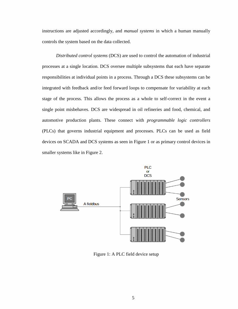
Distributed control systems (DCS) are used to control the automation of industrial
processes at a single location. DCS oversee multiple subsystems that each have separate
responsibilities at individual points in a process. Through a DCS these subsystems can be
integrated with feedback and/or feed forward loops to compensate for variability at each
stage of the process. This allows the process as a whole to self-correct in the event a
single point misbehaves. DCS are widespread in oil refineries and food, chemical, and
automotive production plants. These connect with programmable logic controllers
(PLCs) that governs industrial equipment and processes. PLCs can be used as field
devices on SCADA and DCS systems as seen in Figure 1 or as primary control devices in
smaller systems like in Figure 2.
Figure 1: A PLC field device setup

6
Figure 2: A PLC process network setup
Understanding the manufacturing needs of the industries that use ICS helps to
understand the ICS configurations. There are manufacturing industries and distribution
industries [16]. Manufacturing industries typically involve a single location such as a
factory and are further split into continuous manufacturing process wherein the process
from raw materials to finished product runs continuously and batch manufacturing
process where the process is broken into distinct steps producing a specific amount of the
product. Examples of continuous manufacturing processes include petroleum and
distillation in a chemical plant. Food and consumer goods are examples of batch
manufacturing. The small area of operation allows for greater reliability and performance
in the networking technology used within the factory. Distribution industries, on the other
hand, control devices spread over large distances such as oil and water pipelines and
railway systems and offer less assurance in communication. These systems use leased
lines, radio frequency, and satellite links [15] to overcome these great distances, each of

7
these with their own security and reliability concerns. Distribution industries are typically
designed to handle the reliability and timing challenges that come with long distance
communications.
1.2 Components of Industrial Control
The differences between IT networks and control networks can further be detailed
in the devices and protocols that make up the environment. A Remote Terminal Unit
(RTU) interface with machinery and sensors in modern ICS networks. RTUs govern
industrial equipment and processes. They are lower cost and lower capability than a PLC
and are used in remote stations where less functionality is required and less user
interaction is desired. RTUs often comes equipped with radio capabilities for wireless
communications to the central stations. A control server (or master server) hosts the
control software and sends instructions to the PLCs and RTUs around the network. This
is usually located at the central control facility and is used to collect and process
information relayed from field devices. An Intelligent Electronic Device (IED) is a
“smart” sensor/actuator that may sit between the RTU and the machinery or it may
replace the RTU entirely and communicate directly with the control server. IEDs have
functionality to run simple routines to react to changes in the parameters of the system,
but are usually polled by RTUs or PLCs and given instructions from there.
ICS operators manipulate the system through a Human Machine Interface (HMI).
An HMI is software that allows the control engineers to monitor the elements of the
processes under control. A typical HMI can allow an engineer to set alarms in case
certain limits are exceeded, modify the processes, take manual control in case of
emergency, and read reports on runtime information. HMIs can be located in the control

8
center, on engineer workstations or laptops, and more recently on mobile devices. The
data that is collected or calculated and any triggered events or alarms are usually saved
and stored for later analysis. This data can be collected in a data historian that can reside
on the control network or an outside network with security restrictions in place to prevent
it from communicating in any way with the control network other than receiving
information. A slave historian can be used to duplicate the historian’s data onto a server
on the corporate network for the business to access and analyze.
1.3 ICS Network Devices and Requirements
ICS networking concepts and requirements evolved from a need to rein in the
wiring of early control systems. As described earlier, each sensor used to be wired
directly to the meter displaying its reading to the operator. Each sensor required a
separate wire for each binary digit it was expected to record [19]. This method of wiring
was quickly outgrown and the industry requested a solution from its vendors and
university researchers. The solution was a Fieldbus, a network that connected devices in
the field such as RTUs and IEDs to the central facilities. Fieldbus is a broad term to
describe all the communication technologies that solve this wiring problem. Many
protocols, such as Modbus[20]–[22], Distributed Network Protocol (DNP3)[23][24]–
[26], and Common Industrial Protocol (CIP) family of protocols [27], [28] are used on a
fieldbus network. These protocols are responsible for handling any device identification
in place of individual wires for each sensor. The medium for communication is undefined
for a fieldbus and may include multiple technologies such as Ethernet, serial, satellite
link, telephone lines, or radio frequency [15]. To this end, a modem is a device that can
translate a digital signal into analog for easier transmission over any number of long-

9
distance mediums. One modem would be connected at a remote substation to translate
digital signals from the RTU into analog and another would be located at the central
facility to translate the analog signal back into digital for use.
This research makes heavy use of Modbus, so it may benefit the reader to have a
longer explanation of Modbus in particular. Modbus is an open communication protocol
developed in 1979 by Modicon for use in ICS networks. ICS are difficult to install and
difficult to upgrade and have longer lifecycles relative to corporate networks. This lead to
operators preferring open standards and the proliferation of protocols like Modbus [16].
As described in the specification guide in [29], the base Modbus is a simple, stateless,
call-and-response protocol. It contains a simple addressing scheme allowing for up to 247
devices on a common bus, a field for a function code that tells the target devices which
procedure to run, and a data field that can contain up to 252 bytes for the target device to
act on. There are two versions of Modbus: Modbus RTU and Modbus ASCII. Modbus
RTU transmits raw bytes and uses a specific minimum time between bytes sent over the
bus to distinguish between frames and a Cyclic Redundancy Check (CRC) to detect errors
in transmission. Modbus ASCII operates on ASCII-encoded messages, utilizing two
bytes where Modbus RTU would only require one. Modbus ASCII distinguishes frames
with a colon. Whenever a device receives a “:” it knows a new message has started,
regardless of where the previous message left off. To detect transmission errors, Modbus
ASCII makes use of a Longitudinal Redundancy Check (LRC). The structure of a
Modbus ACSII message is presented in Table 1. This research uses Modbus ASCII for
simplicity.
Table 1: A Modbus ASCII message

10
Start Address Function
Code Sub code Data LRC End
“:” 2 bytes 2 bytes 2 bytes
(optional)
Up to 504
bytes 2 bytes “\r\n”
The growing interconnectedness of ICS networks with corporate networks
and devices have led to incorporation of corporate network technologies. A router is a
networking device that allows communication between logically separated networks.
These are used to allow access to the control network from the corporate network and
vice-versa. A firewall allows a network engineer to closely regulate the connections that
are made across networks. A firewall (sometimes multiple [30], [31]) located at strategic
points such as between the ICS and the corporate network or between the engineers
terminal and the fieldbus can block unwanted network traffic from reaching the ICS. A
remote access point is a device that allows control over the ICS remotely. Such devices
include laptops, tablets, and smartphones that access the control network from anywhere
through a Virtual Private Network (VPN), which encrypts traffic and “tunnels” through a
public network.
Special considerations must be made when designing an ICS network. Each
system is unique in its requirements and goals, and these factors inform the decisions
made in selecting technologies and topologies. Depending on the nature of the industry,
the timing requirements may range from 250 microseconds to 10 milliseconds. A
response time that is less than the sensor’s sample time is recommended [16]. This can
necessitate processing power at a remote substation, as performing computations
remotely might incur too significant of a delay. A distribution industry such as an oil
pipeline would have SCADA components spread over thousands of miles with different

11
options for communications at different substations. The complexity of control needed
for the system might allow simple controllers with predefined routines or might require
high-level decision making from a human operator such as in air traffic control [1]. The
need for high uptime, 99.999% or 5 minutes and 35 seconds per year of allowable
downtime per year in some cases [32], and reliability would push for a system with more
redundancy and alternate forms of communication should one fail. To go along with
availability, the impact of a failure in the system must be considered. A failure in a
nuclear reactor could have significant environmental impacts and would require both
redundant control systems and physical safety mechanisms. Finally, operator safety must
be considered. A control network in a car must be able to detect a sudden application of
the brakes to tighten the seatbelt, apply the automatic braking system, and deploy airbags
if needed.
1.4 Cyber Security for Industrial Control Systems
Industrial Control Systems (ICS) regulate processes that, if compromised, can have a
physical effect on the environment around them. A broken ICS process can cause
damages to the facilities containing the machinery and/or endanger human life [33]. As
with the design considerations varying across industry, so too do the means by which an
attacker can cause harm. Strict timing requirements mean that slowing down response
time would disrupt the system. This is especially true of close-loop systems, where a
transmission time exceeds the sample time. This error can propagate and amplify over
cycles to force the system into an unstable state [34], [35]. Programmable Logic
Controllers (PLCs), Remote Terminal Units (RTUs) and Intelligent Electronic Devices
(IEDs) are designed to be programmed and reprogrammed as needed to suit changing
12
requirements in the system. An attacker could reprogram one of these devices to modify
its behavior or adjust thresholds to effectively disable alarms. An attacker could modify
or fake information being sent to PLCs and Human-Machine Interfaces (HMIs) to
disguise unauthorized changes in the system or cause the operator to initiate inappropriate
actions. As with a corporate or home network, malware-infected workstations can have
degraded system performance or actively disrupt the system by modifying configurations.
An attacker can also interfere with the safety mechanisms such as emergency shutdown
systems, safety shutdown systems, or safety interlock systems [1], [36].
The design of ICS networks makes manipulating SCADA components simple.
ICS networks were originally isolated from corporate networks and the greater networks,
thus network traffic moving across the lines is inherently trusted. Early systems used
specialized software and hardware with proprietary protocols. Modern systems are using
cheap commercial off the shelf (COTS) hardware with open protocols and IT design
principles that promote connectivity with corporate networks and erode the isolation that
control networks used to enjoy [1][5]. While this integration of IT technology allows
corporate network security measures to be utilized, the special considerations discussed
in the previous section can limit their viability. These special considerations can also
require new technologies to be developed.
When considering the CIA triad [37], the priorities for an ICS are different than
traditional IT as seen in Table 2 [2]. Confidentiality is paramount for most IT systems.
Trade secrets, banking information, employee personal information, and other sensitive
data are stored on the IT network. The greatest cost to the organization is in this
information leaking out, so the highest priority is confidentiality. Availability is last

13
because a traditional IT staff would rather have their system go down than have sensitive
information compromised.
Table 2: Priorities of IT and ICS Networks
Priority IT SCADA/ICS
1 Confidentiality Availability
2 Integrity Integrity
3 Availability Confidentiality
Availability is the highest priority for ICS. Downtime of an ICS network could
potentially damage expensive equipment as seen in the Stuxnet attack[6], damage the
surrounding environment as seen in the Maroochy attack [3], deprive the community of
critical utilities as seen in the Ukraine attacks[38], damage the company's reputation, or
cause a loss of metering data, damaging the company's profits. Confidentiality is last
because an ICS operator would rather have an attacker in the system snooping than to
have any downtime. These factors present the challenge to security professionals.
Security professionals face an infrastructure that was built before security was a concern,
equipment that is old enough to be vulnerable to common attacks, and a zero-downtime
mindset that makes applying updates and security patches difficult.
1.5 Vulnerabilities
The National Institute of Standards and Technology (NIST) separates ICS
vulnerabilities into 6 categories: Policy and Procedural, Configuration and Maintenance,
Architecture and Design, Physical, Software Development, and Communication and
Network. Causes of security failures might overlap across categories. Specific systems
may also have unique vulnerabilities as each ICS is specially designed. Some

14
vulnerabilities can be removed or mitigated, while others must simply be accepted. See
Special Publications 800-82[1] and 800-53A[39] for detailed analysis.
Policy and Procedural vulnerabilities are introduced into ICS through lack of
security policies and a relaxed security posture in the organization. Security policies
govern staff and stakeholders on proper use of systems to reduce the attack surface of the
system. As shown above, security of ICS is often not the top priority so such policies can
be scarce. Mitigations of this class of vulnerability include awareness and training
programs to educate employees on proper upkeep of a secure environment, as well as
maintaining a proper written security policy and plans for breaches. Proper authentication
policies for employees such as smart cards and strictly enforced access policies, as well
as proper authorization policies following the principle of least privilege as described in
[37].
Misconfigured or default-configured devices make up Configuration and
Maintenance vulnerabilities. NIST describes this class of vulnerabilities as those that
would be similar to challenges faced by a corporate IT network; namely up-to-date
patches of software and proper use of security controls available from vendors such as
access control policies and firewall rules. The uptime requirements of some ICS networks
as described in the previous sections can make patching and upgrading difficult, with
some vendors recommending staying on outdated versions of software to ensure
functionality or contractually obligating asset owners to involve the vendors in upgrades
or risk voiding warrantees [32]. Legacy ICS components may be no longer supported, but
still in production. Malicious software, or malware, is a common method of attack which
can be mitigated. To go along with access control configurations, deficiencies in logging

15
can prevent detection of abnormal behavior and make forensic analysis of attacks
impossible.
Architecture and Design vulnerabilities arise from inadequate planning of ICS
growth and failure to incorporate security priorities from the beginning of development.
Legacy systems may have been designed before security technologies were widely
available or may have expanded and changed without evaluating the effects of new
capabilities on the organizations security posture. Loosely defined security perimeters
around ICS networks make proper enforcement of security policies difficult. Intermixing
of control and non-control network services and can cause control networks to be
vulnerable to common non-control issues. A control network that depends on services
such as Domain Name System (DNS) on an IT network might see reduced availability as
an IT network typically does not conform to the same uptime standards.
Physical vulnerabilities range from physical access to control equipment to
natural disasters. Improper access to network or control equipment could lead to theft,
damage of hardware, unauthorized changes or additions to software and configurations of
devices on the network, or installation of new unauthorized devices. Most devices, while
properly access controlled from networked ports, have local ports with no access control
capabilities to aid in maintenance. Consideration must be taken when securing safety-
critical equipment to not make access to emergency shutdown functions too difficult for
authorized personnel. Certain natural phenomena such as Electromagnetic Pulses, Radio
Frequency (RF) interference, and power dips and spikes can cause temporary loss of
service or permanent damage to devices and networks.

16
Software Development vulnerabilities cover errors in the design and
implementation of the software running in the environment. Fragile or bug-ridden
software that has not been developed to high-assurance standards (or was developed
before such standards existed) leave holes open for malicious or erroneous behavior to
impact operation [40][41]. Specially designed ICS networks and components make patch
release cycles difficult for vendors of ICS devices. Specific requirements for systems
mean unique software patches made available for certain customers, each with their own
testing cycles, leaving vulnerable components with no mitigations for extended periods of
time. Software lacking security tools such as separate privileges and access controls also
fit into this category.
Communication and network vulnerabilities that are present in traditional IT
networks are present in ICS networks. Unsecured communication across the network or
lack of a managed solution for restricting communication (such as proper firewalls) can
open an ICS network to attack. There are cases specific to ICS networks though; such as
use of proprietary protocols or encryption and simple embedded device drivers that are
unable to handle anything but the most expected network traffic [41]. Previous sections
described ICS networking protocol such as Modbus, but notably absent from the
discussion of the base protocol was any form of authorization or authentication. These
protocols are vulnerable to Man in the Middle attacks wherein a malicious actor
intercepts communications, and to spoofing attacks wherein an attacker masquerades as a
legitimate network device sending fake traffic. There have been efforts to retroactively
add security to open protocols [7] and to update standards to include secure operating

17
modes [23], but these still succumb to errors in design leading to more vulnerabilities
[42].
Each of these classes of vulnerabilities have seen significant effort toward
mitigation from both the private and public sector. Some of the mitigations include new
technology and software developed to fill a hole in security capabilities, while others
involve new methods for applying existing technology. There are numerous best-
practices guides [32], [1], [15], [39], [43] and whitepapers addressing each class that will
be described in the next section.
1.6 ICS Policies & Best Practices
The vulnerabilities described in the previous section have mitigating controls via
both additional technologies and more strict policies. This section describes some of the
industry standard best practices for software configurations, infrastructure designs, and
human policy to harden Industrial Control System (ICS) networks against attack. The
goal of policies is to reduce the effectiveness of attacks against existing vulnerabilities.
As such they can be considered mitigating controls for cases where a security fix cannot
be applied or does not exist. These also follow a defense-in-depth philosophy, working in
tandem to boost the effective mitigation of the system as a whole. These
recommendations come from National Institute of Standards and Technology (NIST) [1],
[39], and industry group whitepapers.
1.6.1 Systems Design
The engineering of a system is more complex than ensuring each technical
component is operating as intended. The definition of a system can change depending on
18
context. Ross Anderson describes a variety of definitions in [44] and summarized below
and applied to ICS.
1. A component such as a network card or cryptographic hardware.
2. A collection of the above plus an operating system, physical networking
devices, and networking protocols.
3. The above plus applications that run on the nodes of the network such as an
HMI.
4. The above plus operators.
5. The above plus management and corporate users
6. The above plus venders and customers
A system is more than its individual components. How the components interact
with one another and how a system might allow the human element to compromise its
integrity must be carefully considered.
The Physical Topology is the physical location and design of facilities in and
around components of an ICS. In an ICS just as in traditional IT, if an attacker has
physical access to a device then that device should be considered compromised. Physical
security is just as important as electronic security and should be closely monitored. All
doors should have locks, locks should be controlled with card readers, and physical
security logs should be monitored just as closely as firewall logs. In highly critical
systems armed guards may be necessary. Similarly, any computer devices used in the day
to day operation of the ICS such as engineering laptops or PLC programming tools
should never leave the area. Just as no unauthorized personnel should be allowed in, no
operations equipment should be allowed out.
Physical topology can extend to environmental considerations for protections
against mistake or malice. In the event a process is disrupted, having physical safeguards
such as spillways to direct overflowing liquid materials and natural berms to prevent

19
contamination outside of the area of operation. Designing physical systems to fail safe is
an integral part of safety considerations, and can act as a means to mitigate certain
security vulnerabilities.
Logical Topology, or Network Topology, is the design for the system’s behavior
and how a system’s components interact with one another. This includes considerations
for how networks are divided, restrictions on network access to certain areas and certain
devices, and policies governing behavior of humans interacting with the ICS. ICS must
be logically separated from any other network it is connected to. A demilitarized zone is
recommended as a buffer between the corporate network and the ICS. This prevents
traffic from flowing directly between the two networks. To further the separation separate
sets of authentication credentials should be used for both networks. If a control engineer’s
credentials on the corporate network are compromised then the impact to the ICS is
limited, if there is any impact at all.
The ICS itself must be split into multiple layers. An attacker should have to
penetrate multiple levels of security before reaching the critical systems. This can be
accomplished with firewalls on the drop of the ICS, between the control server and
PLCs/RTUs, and between the historian and the remote substations. Individual
components of an ICS must also be separated from one another. Traffic between the
control server and a pump at one end of the plant should have no business touching the
assembly line at the other end of the plant. Similarly the pump operator should not have
access to send commands to the assembly line.
Traffic on an ICS can be more strictly defined than traffic on a traditional IT
corporate network. With this in mind any extra functionality provided by devices on the

20
ICS that is not being used such as extra radios, open ports, and web interfaces should be
disabled. Not only does this reduce the attack surface of the ICS, but it also reduces the
amount of monitoring and logging that needs to be done. The simpler nature of ICS also
means operator roles can be more rigorously defined. Roles for operators should be
designed according to the principle of least privilege [45][44]. If a lower level operator’s
credentials are compromised the breach will only affect the systems that operator is
authorized to use.
1.6.2 Configurations
Components of an ICS network must be configured to suit their roles sufficiently
within the design of the system. While many devices might not support security-specific
features such as cryptography or access controls, they can be configured intelligently to
reduce their attack surface and improve the security of the system as a whole.
Additionally, for the devices that do support security specific features, special efforts
should be made to ensure these features are properly enabled, configured, and tested. This
section describes some of these configuration options and considerations.
Address Space Layout Randomization (ASLR) seeks to render shell code and
return-oriented programming exploits difficult by reordering the memory addresses of
elements of a program each time the program is run. ASLR is a setting that affects
software in development. The software must have a specific linker flag at compile time to
enable ASLR. ASLR is supported on Windows operating systems from Vista onward,
FreeBSD, OpenBSD, Linux, Solaris, and OS X 10.7 onward. ASLR compliments data
execution prevention (DEP) technologies. Where ASLR randomizes memory locations,
DEP prevents execution of code from certain parts of memory that are commonly

21
targeted by attackers, such as the heap and the stack. Support for ASLR and DEP is not
common in embedded devices, with only 22% of devices supporting ASLR and 44%
supporting DEP [46].
Application whitelisting is a method to eliminate the problem of having to track
the changing malware trends by only allowing applications to run which have been given
specific permission. Whitelisting software allows an administrator to specify which
executables she wants enabled on the system. Malware that infects the system would
never get a chance to execute. A case study from the Amor Group in 2012 reviewed the
results of applying application whitelisting in the North Sea oil and gas industry [47].
Implementing whitelisting on the oil rigs, ships, and other assets revealed the presence of
previously unidentified malware and helped the team catalog all of the legitimate
software running on the multitude of computer systems. After whitelisting, no
reinfections of systems were detected and a stricter management of applications was
enabled.
As control systems gradually become less isolated, the edge of the network (or
subnetworks if the control system is divided) must enforce proper access controls through
firewalling. If the ICS cannot be air-gapped from the corporate network then strict control
over all physical connections is essential to protecting the network. Firewall strategy for
an ICS is similar to firewall strategy for a traditional IT network. When deciding on a
firewall solution at minimum the firewall should require authentication before any
configuration changes are made, be able to perform self-testing, and be able to perform
logging. Firewall rules must be made according to the whitelist philosophy: traffic is
denied unless it is explicitly allowed. This is vitally important because even the most

22
innocent of traffic can cause problems to an ICS. A simple network enumeration, a
perfectly harmless operation on a corporate network, can cause system outages.
Considering how time-sensitive an ICS can be this “harmless” traffic can consume
enough processing time to effectively render the nodes in the network unavailable. A
firewalling strategy can be split between two separate methods, ingress and egress.
Ingress filtering means filtering network traffic coming into the network from the
outside. Filtering incoming traffic is the first line of defense against malware infiltrating
the ICS. There is very little traffic that should be entering the ICS. Traffic allowed to
enter an industrial control system (ICS), if there is to be any allowed, can be clearly
defined. Consideration can be given to the purpose of incoming traffic, from where the
traffic originates, the communication protocols necessary, whether these operations can
be done locally, and the time of day or week this traffic can be expected. These questions
allow strict rules to be implemented and policies for temporary rules to be enforced.
Egress filtering involves filtering the network traffic leaving the network and
originating from the inside. Since no system is unbreakable, it is important to implement
firewall rules under the assumption that the system has already been compromised. A
compromised system often makes outbound connections to a control server, either to
push data or to receive further instructions. To this end it is necessary to filter outbound
traffic just as much as inbound traffic. If malware finds its way onto the system through
USB, such as described earlier with Stuxnet, then its damages can be limited by blocking
its attempts to make connections outside the network. The same consideration should be
made for egress filtering as ingress, with traffic leaving the network clearly defined
before allowing traffic to egress. Another important consideration is whether the traffic

23
needs to be part of a session, with packets traveling both in and out of the network to
complete transactions. Special hardware, such as the unidirectional gateway described
later, can be used to physically limit data to a single direction should this not be required.
1.6.3 Patch Management and Disaster Recovery
Because of the extremely high importance of uptime, change and patch
management of ICS can be more daunting than traditional IT. Protecting the individual
components of the ICS, the field devices, the historians, and the operation centers at the
operating system and firmware level adds to the security of the ICS as a whole. If an
attacker can compromise a single device by exploiting outdated or misconfigured
firmware then that attacker is now in control of a trusted node and is now operating at
that node’s trust level across the network. However, an improperly tested patch can bring
just as much harm as an outdated patch that has been compromised.
Proper testing of patches is necessary before the patches reach the production
system. One of the major challenges in keeping an ICS up to date is the sheer number of
variables that can be unique to a specific ICS environment. A vendor may not be able to
tailor patches specifically enough to support a given deployment. It is possible a patch
may do more harm than good if not tested well enough. A security patch released by a
vendor must be thoroughly tested on a system as close to production as possible in
functionality before deployment. This problem is not solely the responsibility of the
control engineers. Vendors should be held to a higher standard in creating software and
patches robust enough to handle the vast variability from system to system.

24
Disaster recovery is the ability for a system to return to normal operation after an
incident, whether accidental or by malice. Adverse conditions and disasters will happen
and having procedures in place for these events is crucial to protecting the uptime of the
ICS. This policy solution takes place in the planning stages of the ICS. The ICS must be
designed in such a way that an unforeseen event can safely take down a part of the
network with minimal effect on other parts of the system. To accomplish this each
component of the system should be made redundant. If the first component goes down
the second should be ready to instantly pick up the workload. An often missed
component of redundancy is that components should fail in a way that does not result in
diverted traffic overloading other systems either at the same stage of the process,
upstream, or downstream. A graceful failure should be tested before the system goes into
production. Should the entire system go down it is important to have a disaster recovery
plan in place to get the system producing again. This can mean having a store of product
in reserve while production is restored, or having multiple plants dispersed across
multiple geographic regions which would be unlikely to be hit by the same natural
disaster.
1.6.4 Hardware Device Solution
1.6.4.1 Blue Coat ICS Protection Station Scanner
Blue Coat’s ICS Protection is a software and hardware solution that mitigates the
risk of using USB storage devices on industrial networks. Stuxnet spread so successfully
through removable drives and ICS Protection Station Scanner is designed to limit this
specific attack surface. ICS Protection Station Scanner combines a hardware solution that
resides outside the ICS and a software solution that runs on all Windows workstations

25
within the ICS. Under Blue Coat’s recommended policies any USB removable storage
must be verified by its dedicated appliance before it can be used within the ICS[48]
1.6.4.2 Unidirectional Security Gateway
Waterfall Security’s Unidirectional Security Gateway [49] addresses the problem
of securely isolating the control network while also allowing business users on the
corporate network to perform their job functions. This technology has been used to safely
replicate the plant historian outside the network for the business to read. Transfer (TX)
equipment sits inside the control network and queries the plant historian. The TX
gateway then sends this data through a one-way fiber communication channel to an RX
gateway sitting on the corporate network. The receive (RX) equipment then builds a
faithful replica of the plant historian called a corporate historian on the corporate
network. Corporate users and applications connect to the corporate historian to process
the operating data. The one-way communication is enforced in the hardware of the
gateways. The TX gateway only comes equipped with a laser, the RX gateway with only
a photocell, and data is transferred through fiber. Sending data to the plant through this
technology is not possible. A proposed network design for a unidirectional gateway is
shown in Figure 3.
Another proposed use of this technology is allowing vendor support to
troubleshoot problems on the control network without any actual remote access. A
program records the local engineer’s screen and sends that data through the unidirectional
gateway to the vendor screen. The vendor directs any troubleshooting steps through
telephone to the local engineer. In this scenario the vendor gets visual, real-time feedback
from the system while also ensuring any actions are performed by a local plant engineer.

26
Figure 3: Proposed network design for a unidirectional gateway. Taken from [49]
1.6.4.3 Tofino Xenon Security Appliance
Tofino developed a security appliance specifically for SCADA environments that
resembles a plug-and-play firewall. It is designed to operate between a process network
and the business network. It is capable of filtering messages at layers 2, 3, and 4 of the
OSI model, as well as performing deep-packet inspection to make filtering decisions
based on the specifics of the control network protocol (Modbus, DNP3, Profibus, and the
like) in use. The deep packet inspection of control network protocols is what separates
the Tofino security appliance from a typical corporate firewall solution [50].
1.7 Cyber Attacks
The instances of the aforementioned vulnerabilities being exploited has been
increasing recently as more Industrial Control Systems (ICS) have lost their isolation
from their corporate network counterparts [40][30], [51]. This section describes some
select attacks with information gathered from technical reports and forensic analyses of

27
the attacks after the fact. This section describes three attacks: Maroochy water treatment
facility attacks, the STUXNET attacks, and the Ukrainian power grid attacks. These
incidents were chosen to highlight different threat actors, different vulnerabilities
exploited, and different industries affected.
The Maroochy attacks in 2000 involved a formal employee of the asset owner
using stolen equipment to remotely manipulate water treatment facilities. Vitek Boden, a
disgruntled former employee of Hunter Watertech in Queensland, Australia,
compromised sewage equipment to dump 800,000 litres of raw sewage into local parks
and rivers [3]. Boden used intimate knowledge of the sewage system his former employer
installed to enact revenge on both Hunter Watertech and Maroochy Shire Council. Boden
drove from site to site over a 2 month period using stolen radio equipment to interfere
with signals being sent between the control server and the RTUs in the remote
substations. Boden would craft communication packets to spoof a station on the SCADA
network and send out commands as though he were that station. Because there was no
authentication processes present in the system Boden was able use this method to shut off
pumps, disable communications between components in the system, and disable the
alarms that would have alerted the plant operators to any suspicious activity. After an
investigation, Hunter Watertech determined the problems were caused by a malicious
attacker rather than faulty equipment. Boden was put under surveillance and eventually
caught when stolen radio equipment was found in his car during a routine traffic stop [3].
This attack exploited poor or non-existent security measures from the Configuration and
Maintenance class of vulnerabilities described above. Its complexity was relatively low; a
former employee was able to exploit stolen equipment without needing to develop new

28
software exploits or circumventing many security controls. As demonstrated with
STUXNET, attacks on ICS networks can get significantly more complex.
Stuxnet was an elaborate malware targeting a specific configuration of ICS in
2009 and 2010. It is a definitive example of network isolation not guaranteeing safety
[52]. Stuxnet gained infamy through its unprecedented level of complexity and because
of its notable target in nuclear facilities. Roughly 60% of all infected hosts were found in
Iran, with the remaining hosts spread across Europe, Asia, and the US. The worm was
designed to reprogram a specific set of Siemens PLCs in such a way that the system
being controlled would operate outside of its limits and degrade. It would also forge the
operating data seen on the plant monitors so plant operators would not be able to detect
any differences in the system. The complexity of the malware is readily apparent in the
sheer breadth of its functionality. Symantecs Stuxnet Dossier lists the functionality
described in Table 3, along with the category or categories of vulnerabilities the
capability targeted.
Table 3: Stuxnet Capabilities and Targeted Vulnerability
Stuxnet Capability NIST Vulnerability Category Self-replicates through removable drives
exploiting a vulnerability allowing auto-
execution. Microsoft Windows Shortcut
LNK/PIF Files (Automatic File Execution
Vulnerability (BID 41732))
Configuration and Maintenance
Spreads in a LAN through a vulnerability
in the Windows Print Spooler. Microsoft
Windows Print Spooler Service Remote
Code Execution Vulnerability (BID 43073)
Configuration and Maintenance
Communication and Network
Configuration
Spreads through SMB by exploiting the
Microsoft Windows Server Service RPC
Handling Remote Code Execution
Vulnerability (BID31874).
Configuration and Maintenance
Copies and executes itself on remote Configuration and Maintenance

29
computers through network shares. Policy and Procedure
Architecture and Design
Copies and executes itself on remote
computers running a WinCC database
server.
Policy and Procedure
Communication and Network
Configuration
Architecture and Design
Copies itself into Step 7 projects in such a
way that it automatically executes when the
Step 7 project is loaded.
Software Development
Updates itself through a peer-to-peer
mechanism within a LAN.
Configuration and Maintenance
Policy and Procedure
Architecture and Design
Attempts to bypass security products. Configuration and Maintenance
Policy and Procedure
Exploits a total of four unpatched Microsoft
vulnerabilities, two of which are previously
mentioned vulnerabilities for self-
replication and the other two are escalation
of privilege vulnerabilities that had yet to
be disclosed.
Software Development
Contacts a command and control server that
allows the hacker to download and execute
code, including updated versions
Configuration and Maintenance
Policy and Procedure
Contains a Windows rootkit that hid its
binaries.
Software Development
Fingerprints a specific industrial control
system and modifies code on the Siemens
PLCs to potentially sabotage the system
Configuration and Maintenance
Policy and Procedure
Hides modified code on PLCs, essentially a
rootkit for PLCs.
Software Development
This robustness suggest an immense amount of resources and person-hours
poured into the product and perhaps hints at just how high value the target in Iran was to
the authors. Symantec estimates a team of 5-10 developers and a team of management
and QA engineers were required to produce the malware [52]. Not only did it require a
lot of developers it also required a lot of ground work. Stuxnet used two compromised
digital certificates and four 0-day vulnerabilities. It required a significant amount of
reconnaissance on systems that were never connected to the internet. This means physical

30
access to the systems was required to gather information on the infrastructure, then again
to deploy the worm [6], [52]–[54]. STUXNET targeted state nuclear facilities and was
not meant to spread outside of its specific target. Its collateral damage was limited and
damage to civilian systems was limited. This care is not always taken as shown with
power grid attacks in Ukraine.
A more recent attack on utility infrastructure occurred on the 23rd of December,
2015 [38], [55], [56]. This attack, launched in Ukraine, was the first publicly known
cyber-attack targeting power infrastructure. The attack was able to disrupt power to
225,000 customers spread over 3 different service territories. The attack started off with a
spear fishing campaign and an infected Microsoft Excel document loaded with
BlackEnergy 3 [57], a malware toolkit that allows for connection to a command and
control server. With BlackEnergy 3 the attackers were able to gain persistence on the
power companies' business network and find their way through the VPN connecting the
business and ICS networks. This attack involved at least 6 months of network
reconnaissance and many steps of non-ICS related activities to reach the intended target.
Once on the control network the attackers used built-in commands of the entity's RTUs to
open the breakers in at least 27 substations to cause the outage. The attackers also
overwrote the firmware of serial-to-Ethernet devices on the network to translate traffic
from the operator's Human Machine Interface (HMI) to the Remote Terminal Units
(RTUs) to block plant operators from issuing commands to restore the substations
remotely. A telephone denial-of-service attack was subsequently launched on the
companies' call centers to restrict the flow of information to the customers affected. On a
global scale this attack was relatively small; only affecting 225,000 citizens for roughly 3

31
hours. On a local scale this attack was catastrophic to the power networks and operators
[38].
1.8 Summary
This chapter provided some insight into the motivations and challenges faced by
industrial control systems and their operators. While safety has been a primary concern
for control systems throughout their history, security has only recently become a priority.
As control systems operators gradually opted out of air-gapping their networks in favor
of better remote access, security researchers and malicious attackers alike have descended
upon the field to find and document security holes in control network components new
and old. A robust operator policy, intelligent network design, and utilization of security
mechanisms can help mitigate potential threats, but a critical cyber-physical system with
real-world consequences for failure requires a more formal approach. Chapter 2
introduces and discusses formal methods in software design and development to
guarantee a piece of software will behave in a safe and secure manner, along with
relevant research in the development of formal methods and its application to security
and control systems. Chapter 3 presents a specific issue within control systems security
and outlines the central contribution of this dissertation: a method of applying formal
methods to control system security using TLA+ and seL4. Chapter 4 details the formal
specification of a bump-in-the-wire security preprocessor, presented as a novel
contribution to the field of control system security and as a proof on concept for the
method. Chapter 5 discusses the mechanical model checking results of the specification.
Chapter 6 lays out the design for the security preprocessor in CAmkES. Finally, chapter 7
summarizes these contributions and discusses possible avenues for future work.

32
CHAPTER II
LITERATURE SURVEY
2.1 Introduction
Developments in formal analysis and security have occurred in tandem since the
1970s. Interest in the physical and logical security of data grew as mainframes and
terminals gained widespread use in both the private sector and intelligence communities.
Initially, government security efforts focused on finding and fixing software
vulnerabilities through use of “Tiger Teams” [58], [59]. These teams consisted of
computer experts acting as attackers, finding and exploiting software vulnerabilities then
reporting their results so the vulnerabilities could be fixed. After many rounds of
successful attacks, the Tiger Teams and security community at large concluded the cycle
of finding and fixing security holes was futile – a secure system must be built with an
intention to be secure from the start. Early steps of security research included finding a
definition of secure, or more accurately a method of defining security for a given system.
As can be seen in the research and development efforts in this chapter, formal methods
help do each of the following things precisely:
• Describe a system’s boundaries
• Describe a system’s desired behavior
• Describe a system’s desired properties
• Prove a system meets its specification
• Determine the circumstances under which the system does not meet its
specification

33
Funding from the National Security Agency (NSA) poured into the security
community [59], and from there flowed into the formal methods community. The early
research funded by the U.S. intelligence agencies culminated in the Trusted Computer
System Evaluation Criteria, also known as “The Orange Book”, first published by the
Department of Defense in 1983 [60]. This document provided a metric for comparing the
security posture of different computer systems, a guideline for vendors in the
development of secure computer systems, and a means for specifying security
requirements in government contracts. For example, for a system to be “A.1” certified
according to “The Orange Book”, the security requirements must be formally specified,
the system must be formally modeled, and a formal proof must exist that the model meets
its specification. The works described in this chapter are efforts to apply the A.1
certification criteria to an increasingly complex set of systems in an increasingly diverse
set of scenarios, as well as efforts to bring a more formal approach to security of cyber
physical systems.
2.2 Formal Methods
Progress of a society can generally be observed by the increase in complexity of
its mechanisms, both social and technological. As complexity increases, it becomes easier
to make errors in the design and implementation of systems –the accelerating rate of
vulnerability reporting seen in [61] can attest to this. Formal methods are means for
allowing engineers to develop increasingly complex systems while retaining a high
degree of reliability. When a system is formally described, it can be better understood.
Leslie Lamport, a pioneer in reasoning on distributed systems and inventor of Latex[62]
34
and Temporal Logic of Actions (TLA)[63], says on pages 1 and 2 in his book Specifying
Systems [64]:
Writing is nature’s way of letting you know how sloppy your
thinking is… Mathematics is nature’s way of letting you know how
sloppy your writing is… Formal mathematics is nature’s way of letting
you know how sloppy your mathematics is.
There are a variety of formal method techniques, each seeking to remove logical
errors from systems. The four key types of formal method techniques discussed in this
chapter are Model checking [64], Deductive Theorem proving [65], Abstract
interpretation (also known as static analysis) [66], and Type inference [67]. Model
checking involves creating a finite state machine that acts as a model of a real-world
system and relevant propositions; the checker (human or machine) attempts to show that
propositions hold in every state. Deductive theorem proving starts with a set of axioms
and deduces properties of the system the axioms describe. Abstract interpretation tries to
create an abstraction of code to form a less precise, but tractable model that can be
reasoned upon. Finally, type inference is a completely automated method for deducing
variable types at compile time and is available in many strongly-typed languages today
[67]. Each of these techniques has its own strengths and weaknesses as discussed in the
following sections.
2.2.1 Model Checking
Model checking creates a specification, or description of the system using the
system’s requirements as a starting place. The specification includes defining desired
properties and structuring each individual piece within the system [68]. Formal
specification introduces rigor using specification languages with mathematically defined

35
syntax and semantics. Even though it is only the first step in the formal methods process,
the act of formally specifying a design – describing a design precisely – can be enough to
discover and remove inconsistencies and flaws in a non-formal design. Case studies using
formal specifications at Oxford University, IBM, and Lockheed alone have shown
reduction in production costs and improvement in code quality (fewer errors, earlier
detection of errors) [11], [13], [14]. A specification can be as abstract or as granular as
necessary, ranging from describing a perfect oracle that returns perfectly encrypted
ciphertext to describing individual memory operations.
Model checking is a method for automating verification of specifications [69],
[70]. A model checker typically comes with a custom language parser to allow an analyst
to formally describe a system and requirements. A model checker requires the analyst to
describe the system as a finite-state specification Φ and the desired property or set of
properties to prove ϕ. Such a system can be described using temporal logic and drawn out
in Kripke structures [71]. Kripke structures take the form of M = (S, I, R,
L)where S is a finite set of states, I is an initial state in S, R is a subset of S × S such that
∀s ∈ S, ∃s' ∈ S, (s,s') ∈ R where s and s’ are individual states, and L is an interpretation
function that maps to the alphabet of states [69]. An example of a Kripke structure of a
microwave is seen in Figure 4, taken from a lecture by Edmond Clarke on [69].
The properties to be verified can be described using linear temporal logic
[72][73]. Equations can take the form of propositions such as 𝐴 ⇒ 𝐵 (A implies B);
Boolean operations such as AND, OR and NOT; and temporal operators. Temporal
operators can be described with statements such as Xa for “a is true in the next state,” Fa
for “a will eventually be true,” Ga for “a is globally true”, and a U b for “a is true until b

36
is true.” Ga can also be expressed as “a will be true in every state” and is called an
invariant. This is sometimes called a safety property, as it specifies a dangerous state the
system should never reach. The other operators can be used to describe liveness
properties, or properties that are used to verify a system will eventually reach some set of
states.
Figure 4: An example Kripke structure. Taken from [69]
The model checker can then automatically verify the property shown in Equation
(1), that the specification models the requirements (i.e., the specification meets the
requirements and desired properties). Model checking as a discipline is most useful when
it finds counterexamples to requirements. If a model to be checked is not valid, a checker
can discover difficult to find, easily checked, counter examples that can be fixed.
However, if a model is valid, there is no easily checked method for the model checker to
verify that. The most a model checker can say is that it could not find any
37
counterexamples. Once a counterexample is found, an exact trace to the counter-example,
or bug in the system being specified and checked, is available. This is useful when the
nature of concurrent systems often produces exceedingly subtle bugs [possible ref to one
such case].
𝝓 ⊨ 𝝋 (1)
This method has classically been used in the design phase of software
development. Properties of the design can be reasoned on before any investment has been
made into writing code. This allows for fundamental problems to be captured and fixed
early and cheaply. This is not to say checking a model is easy. Even simple programs can
suffer from the State Explosion Problem, wherein the number of states to be checked
grows exponentially. Figure 5 shows the state space of a first-in-first-out (FIFO) queue
algorithm containing more than 3800 states and more than 9600 transitions, with a
maximum length of 3 elements taken from [74]. Such a small FIFO queue might not be
practical, but it gives an example of the state explosion of even relatively simple
programs.
Figure 5:A FIFO queue capped at 3 elements

38
The state explosion problem has seen significant research efforts. State explosion
is present in parallelized systems, verification of which is paramount for adoption of such
techniques in industry. An n-bit counter will have 2n states, while m interleaved processes
with n states each will have nm states. Edmund Clarke opines that there have been four
big breakthroughs in the state explosion problem thus far: Symbolic model checking with
binary decision diagrams [75], partial order reduction [76]–[78], bounded model
checking [79], and counter-example guided abstraction refinement (CEGAR) [80].
Symbolic model checking with ordered binary decision diagrams were introduced
in the mid-1980s. Representing the states as a Kripke structure invited applications of
graph theory into reducing the state space. Before this, states and transitions were
represented explicitly with linked lists in memory as any directional graph might be. In
1986, Randal Bryant showed that larger specifications could be checked if their states and
transitions were intelligently ordered into a binary decision diagram rather than a naïve
linked list, reducing the states to be checked [75]. The binary decision diagram removes
states and transitions that are implied in the specification and thus do not need to be
explicitly written and computed, saving space and processing time. It should be noted
that binary decision diagrams do not improve worst-case complexity of a model and in
practice have been unpredictable in their complexity-savings.
Partial order reduction is a method for reducing the amount of redundant work
done while processing models of concurrent systems. This method takes advantage of the
commutative nature of some processes. Often, processing step A then step B will produce
the same result as processing step B then step A. Using this property of some distributed
processes, redundant branches of states can be eliminated from the necessary

39
computation to exhaust the search space. Partial order reduction was developed
independently in the early 90s in [76]–[78].
Bounded model checking introduces satisfiability solvers to the model checking
domain. Clarke et al. found that for certain properties, especially invariants, satisfiability
solvers can find counter examples must faster than symbolic model checking and often
without the exponential space requirement of binary decision diagrams [79]. The idea is
to create a propositional formula from the states and transitions. This formula is Boolean
– meaning its variables are either true of false and can be manipulated so the formula
evaluates to either TRUE or FALSE. If the variables can be manipulated such that the
formula evaluates to TRUE, the formula is said to be satisfiable. In bounded model
checking, if the formula is satisfiable then a desired state can be reached within a set
number of transitions. This method is somewhat restricting in that it can only test for
certain properties. It is also not complete – at this time there is no way to know how long
the bounded model checker must run before a counter-example is found if one exists.
Finally, Counter-Example Guided Abstraction Refinement (CEGAR), also known
as localization reduction, is a means for automatically generating a model from a
program, then automatically abstracting away unnecessary complexity within a model
while checking [80]. The checking algorithm generates an over-approximation of the
program that includes all the behaviors of the program by creating a state for every
possible assignment of every possible variable. The transition relation is generated
through the changing of variables in the program. If the specification holds on the
abstraction, it is shown that it will hold for the concrete model. However, if a counter
example is found, the algorithm checks if the counter example exists in the concrete

40
program. If the counter example is found in the concrete program then this result is
returned. If the counter example is not found in the concrete program, then it was
introduced through the abstraction process. The abstraction is refined until the counter
example is removed and the process repeats. A discussion of the advancements in
CEGAR can be found in [80].
2.2.2 Theorem Proving
Theorem proving is the derivation of proofs from a formal system of axioms and
inference rules. A developer expresses the program to be reasoned on and the desired
properties of the systems as formulas then works to prove the properties from the given
axioms within the formal system. Such work can involve deriving new definitions from
the axioms and constructing intermediate lemmas to aid in the proving process. Though
much of this work can be done by hand, this research focuses on automated and
interactive (human-guided automation) theorem proving. Much of the work found in
section 2.3 relies heavy theorem proving, and more discussion can be found in [65].
2.2.3 Standards and Certifications
Verifying systems can be prohibitively expensive. The larger the system the
greater the expense of formal verification [11][81]. Full verification is not always
necessary though and, depending on the system and use cases, value can be derived from
a partial verification. Specific safety or security-critical properties of systems can be
reasoned and proved at a reasonable cost. There are multiple industry- and field-specific
standards for partial and full verification.
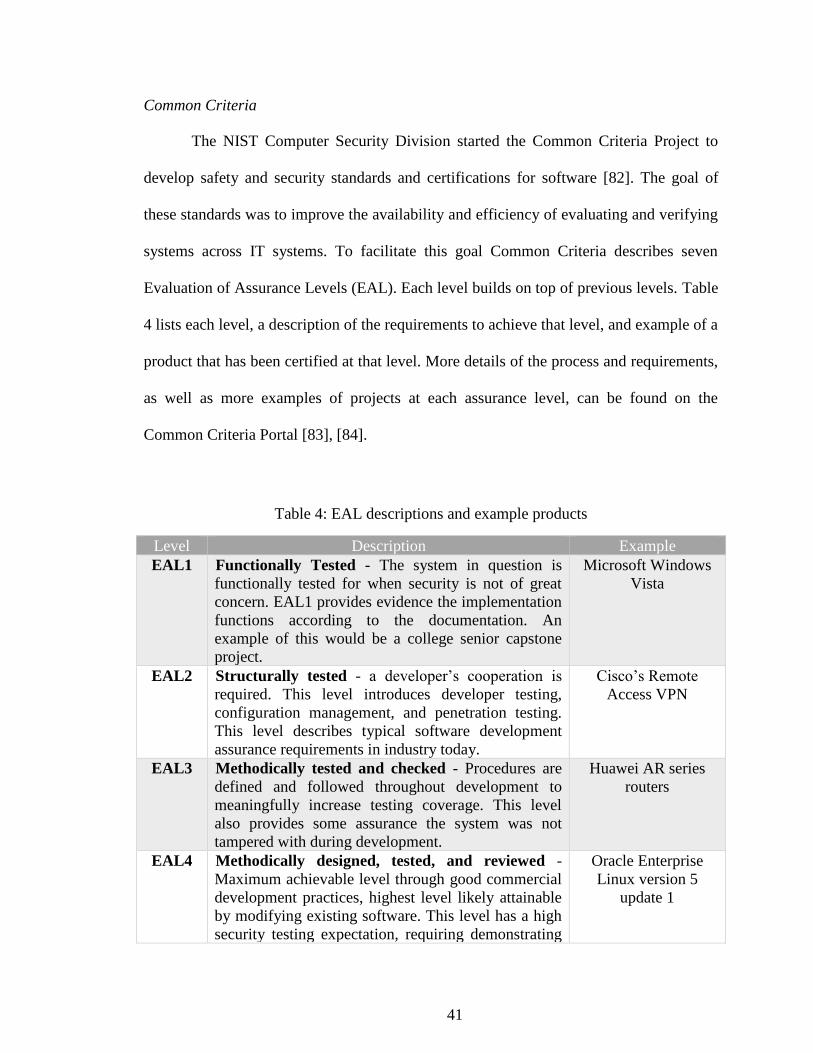
41
Common Criteria
The NIST Computer Security Division started the Common Criteria Project to
develop safety and security standards and certifications for software [82]. The goal of
these standards was to improve the availability and efficiency of evaluating and verifying
systems across IT systems. To facilitate this goal Common Criteria describes seven
Evaluation of Assurance Levels (EAL). Each level builds on top of previous levels. Table
4 lists each level, a description of the requirements to achieve that level, and example of a
product that has been certified at that level. More details of the process and requirements,
as well as more examples of projects at each assurance level, can be found on the
Common Criteria Portal [83], [84].
Table 4: EAL descriptions and example products
Level Description Example
EAL1 Functionally Tested - The system in question is
functionally tested for when security is not of great
concern. EAL1 provides evidence the implementation
functions according to the documentation. An
example of this would be a college senior capstone
project.
Microsoft Windows
Vista
EAL2 Structurally tested - a developer’s cooperation is
required. This level introduces developer testing,
configuration management, and penetration testing.
This level describes typical software development
assurance requirements in industry today.
Cisco’s Remote
Access VPN
EAL3 Methodically tested and checked - Procedures are
defined and followed throughout development to
meaningfully increase testing coverage. This level
also provides some assurance the system was not
tampered with during development.
Huawei AR series
routers
EAL4 Methodically designed, tested, and reviewed -
Maximum achievable level through good commercial
development practices, highest level likely attainable
by modifying existing software. This level has a high
security testing expectation, requiring demonstrating
Oracle Enterprise
Linux version 5
update 1

42
resistance to a medium level attack. Assurance comes
in the form of a detailed design specification.
EAL5 Semi-formally designed and tested - This is the first
level that requires some specialized security
engineering and is beyond the scope of general good
development practices. Software that reaches EAL5
likely was targeting EAL5 from the start of
development. Extra cost beyond the good
development practices is usually minimal. This level
requires semiformal design descriptions and a
structured, analyzable architecture.
Samsung S3FT9PE
16-bit RISC
Microcontroller for
Smart Card
EAL6 Semi-formally verified design and tested - When a
higher cost for a high level of assurance and security
is acceptable. A formal model of the most important
security policies is required and a semiformal design
specification. The testing requirements grow stricter:
documentation of developer testing, independent
recreation of test results, and independent penetration
testing with a high level of attacker skill. EAL6
represents a highly structured design, architecture,
and vulnerability analysis.
Crypto Library
V3.1.x
EAL7 Formally verified design and tested - The highest
level when security and safety assurance is of the
highest importance. EAL7 requires full analysis using
formally verified design and implementation as well
as comprehensive and independently confirmed
testing procedures.
Tenix Interactive
Link Data Diode
Device Version 2.1
DO-178B
DO-178B is a standard for avionics software developed by Radio Technical
Commission for Aeronautics. It defines five levels of safety criticality that help judge the
priority that should be given to the assurance of software [85]. Table 5 lists and describes
each level.
Table 5: Criticality Levels of DO-178B Standard
Criticality Level Description
No effect This software does not affect safety at all.
Minor This software reduces safety or efficiency of airplane but not
beyond capabilities of the crew to handle without injury.
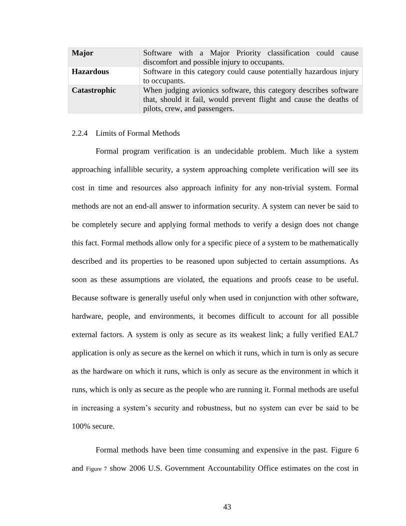
43
Major Software with a Major Priority classification could cause
discomfort and possible injury to occupants.
Hazardous Software in this category could cause potentially hazardous injury
to occupants.
Catastrophic When judging avionics software, this category describes software
that, should it fail, would prevent flight and cause the deaths of
pilots, crew, and passengers.
2.2.4 Limits of Formal Methods
Formal program verification is an undecidable problem. Much like a system
approaching infallible security, a system approaching complete verification will see its
cost in time and resources also approach infinity for any non-trivial system. Formal
methods are not an end-all answer to information security. A system can never be said to
be completely secure and applying formal methods to verify a design does not change
this fact. Formal methods allow only for a specific piece of a system to be mathematically
described and its properties to be reasoned upon subjected to certain assumptions. As
soon as these assumptions are violated, the equations and proofs cease to be useful.
Because software is generally useful only when used in conjunction with other software,
hardware, people, and environments, it becomes difficult to account for all possible
external factors. A system is only as secure as its weakest link; a fully verified EAL7
application is only as secure as the kernel on which it runs, which in turn is only as secure
as the hardware on which it runs, which is only as secure as the environment in which it
runs, which is only as secure as the people who are running it. Formal methods are useful
in increasing a system’s security and robustness, but no system can ever be said to be
100% secure.
Formal methods have been time consuming and expensive in the past. Figure 6
and Figure 7 show 2006 U.S. Government Accountability Office estimates on the cost in

44
money and time for climbing the ladder of common criteria levels. The figures show the
resources required for just the evaluation piece of the certification for government
projects that pursue the certification. Higher levels of verification may also negatively
impact performance of an application as concessions might be necessary to model the
system more efficiently and prove properties [81].
Figure 6: Range of costs required for
completing product evaluations at
various evaluation assurance levels.
Adapted from GAO report [24]
Figure 7: Range of sample cost of NIAP evaluations
to vendors by evaluation assurance level. Adapted
from GAO report [24]
2.3 Verification
Modern cryptography is an intersection between mathematics and computer
science. Cryptography can be thought of in two parts: cryptographic primitives and
cryptographic systems. A cryptographic primitive is the smallest piece of a cryptographic
routine that has security properties (for example, a one-way hash algorithm or an
encryption algorithm [86]). Cryptographic systems use primitives as building blocks to

45
achieve security goals like keeping secrets and authenticating users. Primitives are
difficult to mathematically prove secure, and usually rely on heuristic security arguments
such as maturity of the algorithm and lack of weaknesses found by the community [87].
Cryptographic systems, on the other hand, can be proven secure when the primitives are
assumed secure [88]. While this survey does not go into advances in cryptography, the
research summarized in this section describes relevant advances is ensuring the code that
implements the cryptographic primitives is correct.
2.3.1 Verification of a Cryptographic Primitive: SHA-256
Code that implements cryptographic primitives correctly is valuable in raising the
level of available security, as a single correct implementation of a widely used primitive
can be used everywhere. Andrew Appel presented his work on formally verifying SHA-
256, the Secure Hash Algorithm with a 256-bit digest [88]. SHA-256 is part of the SHA-
2 family of hash functions published by the NSA in 2001. Appel specifically looked
OpenSSL’s implementation of SHA-256, noting that because his proof work applies to
the code and not to the algorithm itself, the many years of open-source scrutiny that
OpenSSL has endured is still a valuable argument to its resilience against attack. The
work shows, through a machine checked proof, that OpenSSL’s SHA-256 correctly
implements the formal specification of SHA-256 provided by the U.S. government in the
Federal Information Processing Standards (FIPS) 180-4 Secure Hash Standard [89].
Appel’s research served as a stress test for the Verifiable C program logic for the
C language and an example of how the Verified Software Toolchain (VST) can be
practically utilized. Verifiable C logic has been proven to be sound with respect to the
semantics of CompCert C, a subset of C digestible by the CompCert compiler [90]. This
46
means code properties that have been proven in Verifiable C hold for the source code.
CompCert has also been proven correct [90], meaning that properties that have been
proven for the source code will hold in the compiled code. Thus, it can be shown that the
compiled code for the SHA-256 algorithm satisfies its specification in Verifiable C. The
proof process required started by building a functional specification, or a formalization,
of the FIPS 180-4 standard in a mechanized proof assistant called Coq [91]. As this is a
process done by a human, one might ask, “how can we trust that this formalization
correctly describes the standard?” Appel points out that this trust is unnecessary, as even
if the translation is incorrect, the properties described by the standard can still be proven
in the functional specification. This work serves as a building block for future work on
verifying higher order cryptographic functions, and on verifying entire cryptographic
libraries.
2.3.2 Verified correctness and security of OpenSSL HMAC
Building on the SHA-256 verification work of Appel, Beringer et al. used a
similar method to extend the verification to include OpenSSL’s Keyed-Hash Message
Authentication Code (HMAC) algorithm [87]. This research uses the FIPS 198-1
standard for HMAC [92] and verifies that OpenSSL’s HMAC code correctly implements
FIPS 198-1 as with the previous work, but goes further than previous work to show that
the standard correctly holds its intended cryptographic properties.
HMAC is an authentication algorithm often used in communication protocols.
When using HMAC, the sender of a message m uses a secret key k that has been pre-
shared with the intended receiver. The sender computes the authentication code
s=HMAC(m,k), then attaches s to the message. When the message reaches the receiver, it

47
computes the authentication code s’ = HMAC(m,k), then verifies s’=s. Ideally, an
attacker does not know k and could not compute s. If the receiver determines s’=s, it
could trust that the message originated from the sender (as opposed to an attacker), and
has not been tampered with. FIPS has requirements on the strength of the hashing
function that can be used, but the HMAC specification can be generalized (without
specifying the cryptographic hash algorithm used) as in Equation ((2.
𝑠 = 𝐻𝐴𝑆𝐻((𝑜𝑝𝑎𝑑 ⊕ 𝑘)(𝐻𝐴𝑆𝐻(𝑖𝑝𝑎𝑑 ⊕ 𝑘)𝑚) (
(2)
The verification steps built off both Appel’s work and earlier cryptographic proof
work by Bellare on HMAC security properties [86], [93]. The first steps were to
formalize specifications within the Coq proof assistant. The specifications are FIPS 198-1
and FIPS 180-4 for HMAC and SHA-256 respectively, Bellare’s function for the HMAC
algorithm (with pre-existing proofs), the API for OpenSSL header files for HMAC and
SHA-256, and finally assumptions made about the security properties of the underlying
cryptographic hashing algorithm. Next, the formalized specifications for Bellare’s
HMAC and the FIPS HMAC were shown to be equivalent, demonstrating that the
security proofs derived from the earlier work apply to the later standard. Further, the
formalized assumptions (common for pseudorandom functions) allowed new
cryptographic security proofs to be derived from the standards. Finally, the process of
translating from formalized specification into verified compiled binary1 is followed as
described earlier. Beringer’s research advanced the pursuit of a widely available,
verified-secure, cryptographic library.
1 The source, proof, and executable files can be found on Princeton’s VST Github Repository
(https://github.com/PrincetonUniversity/VST)

48
2.3.3 HACL∗: A Verified Modern Cryptographic Library
A collaboration between Microsoft Research and Inria has been pushing the state-
of-the-art in cryptographic verification. In 2017, this collaboration presented the High
Assurance Cryptographic Library (HACL*), a suite of formally verified implementations
of cryptographic primitives and cryptographic systems [94]. HACL* specifically targeted
the minimalist NaCl cryptographic library and API for verification work, as other
libraries like OpenSSL are complex and unsuited to verification. NaCL (pronounced
“salt”) was developed to improving the state of the art on cryptographic library security,
speed, and usability by simplifying and optimizing a core set of widely-used
cryptographic functions [95], [96]. TweetNaCl, a particularly minuscule implementation
of NaCl, fits into 100 tweets and implements ChaCha20 and Salsa20 stream ciphers, the
SHA-2 family of cryptographic hash functions, Poly1305 and HMAC authentication,
Curve25519 elliptic curve encryption, and the Ed25519 elliptic curve signature scheme
[97]. Each of these were verified and combined into a library of about 7000 lines of code
that supports the NaCl API, and TLS-specific APIs used by OpenSSL, NSS, and miTLS.
Research on HACL* stated three goals: memory safety, functional correctness,
and secret independence. Memory safety means the software never reads or writes at
invalid memory locations. This can be achieved through strict coding practices such as
ensuring no operation reads or writes past the last cell of an array and properly
deallocating memory to leave no dangling pointers. Certain modern languages, such as
Python and Java, include garbage collection techniques that manage memory for the
coder and produces memory-safe code. However, this convenience is paid for with a
performance reduction that can be unacceptable for cryptographic applications. The

49
second goal, functional correctness with respect to the published standards, has been
explained earlier. Finally, HACL* also strives for secret independence to eliminate
certain classes of side-channel attacks. Secret independence is a coding technique that
ensures:
1. Secrets cannot be used to decide what code executes next
2. Secrets cannot be used to decide what memory to access
3. Secrets cannot be used as input to instructions with a variable time
These methods ensure that a secret cannot affect how much time a particular piece of
code takes to execute. By disconnecting the execution time from the secret, an attacker
would not be able to weaken the security by timing inputs and outputs.
Microsoft and Inria’s techniques differ from those previously discussed. Work on
HACL* relies heavily on type-checking, instead of the automated theorem proving of
previously discussed works, though theorem proving is still used when required. A
formalized specification is still required and is created from the algorithm standards, but
using F* language (and its subsets) rather than Coq. Then, an optimized implementation
is written in Low* (a subset of F* that efficiently compiles to C) and the proof work is
done to show the implementation and formal specification are equivalent. Finally, the F*
code is compiled to verified C code with the KreMLin compiler. At the moment,
KreMLin, the F* type checker, and the theorem proving tool Z3 are unverified and must
be trusted [94].
2.3.4 Breaking and fixing the Needham-Schroeder Public-Key Protocol using FDR
Data in motion can be particularly tricky to secure correctly. Sending an
encrypted message from Alice to Bob, when both share the secret key and understand the
algorithm, might be trivially easy to analyze, but network protocols are rarely so simple.
What if the message is intended for more than one person? What if the different parties

50
don’t have a pre-shared secret key? What if the parties understand multiple encryption
algorithms and must select one? How can one party be sure of the other’s identity? How
can the sender ensure the message that is received has not been tampered with?
Answering any permutation of these questions can grow a network protocol beyond what
can be trivially understood, and often lead to mistakes that break the security of the
protocol without breaking the cryptographic primitives the protocol employs. The next
two works represent formal verification efforts in networking protocols.
One of the foundational papers in formal analysis of secure networking protocols
is Gavin Lowe’s 1996 work on the Needham-Schroeder Public-Key Protocol [98].
Needham-Schroeder was used to establish mutual identity between two agents, an
initiator A and a responder B. Public key cryptography is employed, meaning each agent
has an associated public key which can be found on a public key server, and an inverse of
the public key that is kept secret. This protocol also employs a nonce, a unique number
included in the message to keep track of messages that have already been sent. The nonce
is used to prevent an old message from being reused by an attacker. The important steps
of the protocol can be described formally in Equation (3). Na and Nb are nonces generated
by A and B respectively. {m}PK(B) indicates a message encrypted with B’s public key.
This message can only be decrypted using B’s private key, thus ensuring only B can read
the message.
Message 1. A → B ∶ A. B. {Na. A}PK(B)
Message 2. B → A ∶ B. A. {Na. Nb}PK(A)
Message 3. A → B ∶ A. B{Nb}PK(B)
(3)

51
Lowe modeled the protocol and checked it using Failures Divergences Refinement
Checker (FDR). The attacker is assumed to have full access to messages traversing the
network, but no ability to break encryption. All normal activities, such as decrypting
messages encrypted with the attacker’s public key and sending new messages are
permitted. The attacker can also replay old messages, with or without knowing the
encrypted contents of the message. The FDR checker produced a breach of security when
checking that the responder (B) will only start a session with the initiator A if A took part
in the protocol run. The model checker found this to not be the case, producing the steps
seen in Equation (4) to breach the protocol’s security guarantees. These steps show an
attacker I can use two different runs of the protocol to fool B into thinking it is
communicating with A while sending messages to I. Lowe goes further to propose a fix
to this vulnerability with proofs that the proposed fix works. Needham-Schroeder is a
large component of widely used Kerberos cryptographic system [99].
Message α. 1. A → I ∶ A. I{Na. A}PK(I)
Message β. 1. I(A) → B ∶ A. B. {Na. A}PK(B)
Message β. 2. B → I(A) ∶ B. A. {Na. Nb}PK(A)
Message α. 2. I → A ∶ I. A. {Na. Nb}PK(A)
Message α. 3. A → I ∶ A. I. {Nb}PK(I)
Message β. 3. I(A) → B ∶ A. B. {Nb}PK(B)
(4)
2.3.5 Implementing TLS with Verified Cryptographic Security
The original communication protocol of the internet, Hypertext Transfer Protocol
(HTTP), did not include any means for encrypting transmitted data, requiring sensitive
information such as usernames and passwords and credit card information to be sent in
plaintext. Secure Hypertext Transfer Protocol (HTTPS) is the current solution for
securing general internet traffic. HTTPS is built using Transport Layer Security (TLS),
TLS is itself is a suite of many cryptographic primitives and systems. The wide variety of

52
implementations, supported protocols, and versions of TLS installed on servers leaves the
state of web security an unmanageable mess. Project Everest is a collaboration between
Microsoft Research and Inria to transform the formal specification for the newly finalized
TLS 1.3 standard into a portable library [100]. This project produced many relevant tools
and supportive libraries to aid in the proofs and translations required to produce verified
assembly. The scope of the Everest project can be seen in Figure 8.
Figure 8: The verified components of the TLS1.3 suite. Image from https://project-
everest.github.io/
The verified libraries are only half of the contributions of the Everest project. The
authors note that software is not static; as the years pass and the web landscape evolves,
changes will need to be made to the TLS 1.3 standard, then added to the Everest portable
libraries. Changing verified code is not easy, and few organizations are capable of
modifying verified code without compromising the proofs and properties. The Everest
team will probably have to continually support the project, but future projects might be

53
undertaken by less-funded organizations with fewer verification experts thanks to the
supported tools developed alongside. These tools include:
1. HACL*: Seen in section 2.3.3
2. Low*: a subset of F* targeting low-level programming that allows finer
optimizations
3. KreMLin: a compiler (unverified currently) that extracts Low* to C
4. Vale: A tool for writing verified and high performance assemble code
2.3.6 The Temporal Logic of Actions, TLA+
Early research in formally specifying software focused on sequential actions and
produced tools that could express and reason on sequences with an acceptable level of
complexity. These tools and approaches struggled when tasked with modelling
concurrent systems [63]. Efforts to extend these tools to be applicable to concurrent
systems, usually by replacing predicate calculus with temporal logic, could not reduce the
computational complexity to be practical enough for use. Temporal reasoning on an
entire system can be prohibitively expensive. In 1994, Leslie Lamport presented his work
on modelling concurrent systems through use of actions [63]. While work focused on a
single state of a specification, Lamport’s actions comprised assertions about pairs of
states. Temporal Logic of Actions allows much of the temporal reasoning that was
consuming computer power and brain power to be replaced with standard, non-temporal,
reasoning about actions.
TLA+ is a formal modeling language developed by Leslie Lamport with a focus
on modeling and reasoning on concurrent systems [64][101]. PlusCal is an “algorithm
language” used to model algorithms in a much more expressive fashion than a typical
programming language. Both TLA+ and PlusCal use mathematical notation to expand the
reach of a model beyond a programming language to allow for more rigorous definitions

54
and descriptions of algorithms and systems[101]. The inclusion of mathematical notation
also facilitates model checking and proofs on properties of systems and algorithms.
PlusCal, a more programmer-friendly route into the TLA+ toolchain, can be
automatically translated into TLA+ and used with the TLC model checker. The TLC
model checker can be described as a brute-force checker that will explore all states up to
a certain number of state transitions and alert on any properties that have been violated
and give a trace of the steps to violate such property.
2.3.7 Use of Formal Methods at Amazon Web Services
Amazon has published at least two experience reports on using formal methods in
the design of their web services platform, specifically with TLA+ [102], [103]. Amazon
has found multiple benefits while incorporating formal specification into their
development process. The first and likely most obvious is finding existing bugs in their
platforms. Table 6 lists some of the results of checking the formalized models of systems
within Amazon’s ecosystem, with multiple bugs usually found in less than 1000 lines of
specification code. The second benefit is an increase in understanding of designs for new
systems, or new features for existing systems. Instead of building a naïve design then
modifying it to handle what might go wrong, the new design process places more focus
on “what needs to go right” from the start. This prevents edge cases from presenting new
and unimagined ways for the systems to fail. A third benefit described in the experience
report is that engineers could proceed with applying changes, whether increasing
scalability or increasing existing performance, with greater confidence. Downtime in
production services is expensive, and the risk of extended downtime must weigh into the
analysis of whether an upgrade is worth the cost. Making the proposed changes to the
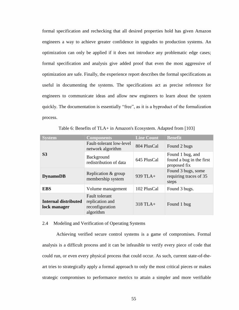
55
formal specification and rechecking that all desired properties hold has given Amazon
engineers a way to achieve greater confidence in upgrades to production systems. An
optimization can only be applied if it does not introduce any problematic edge cases;
formal specification and analysis give added proof that even the most aggressive of
optimization are safe. Finally, the experience report describes the formal specifications as
useful in documenting the systems. The specifications act as precise reference for
engineers to communicate ideas and allow new engineers to learn about the system
quickly. The documentation is essentially “free”, as it is a byproduct of the formalization
process.
Table 6: Benefits of TLA+ in Amazon's Ecosystem. Adapted from [103]
System Components Line Count Benefit
S3
Fault-tolerant low-level
network algorithm 804 PlusCal Found 2 bugs
Background
redistribution of data 645 PlusCal
Found 1 bug, and
found a bug in the first
proposed fix
DynamoDB Replication & group
membership system 939 TLA+
Found 3 bugs, some
requiring traces of 35
steps
EBS Volume management 102 PlusCal Found 3 bugs.
Internal distributed
lock manager
Fault tolerant
replication and
reconfiguration
algorithm
318 TLA+ Found 1 bug
2.4 Modeling and Verification of Operating Systems
Achieving verified secure control systems is a game of compromises. Formal
analysis is a difficult process and it can be infeasible to verify every piece of code that
could run, or even every physical process that could occur. As such, current state-of-the-
art tries to strategically apply a formal approach to only the most critical pieces or makes
strategic compromises to performance metrics to attain a simpler and more verifiable

56
design. Some designers may only wish to verify certain properties of processes, while
leaving others to traditional testing methods. An operating system presents a level of
complexity that must be strategically planned for and verifying operating system
properties have produced valuable insight into the problem of verifying security at a large
scale. Presented here are examples of formal methods applied to operating systems.
2.4.1 The Bell-La Padula model
The state of computing in the 1960s and 1970s encouraged time-sharing strategies
for companies and agencies that had trouble covering the costs of monolithic mainframes
on their own. For agencies that handled classified data, a separate mainframe was
required for each of the independent security levels. While time sharing presented a
major cost-saving opportunity, it also presented a novel risk in handling classified
processes, as multiple security levels would run on the same hardware and data. A high
degree of assurance that processing artifacts of each security level was kept separate was
required. There are many examples of insecure software and systems that were built only
focusing on function, that patch security holes after-the-fact [61], [104]–[106].
David Bell and Len La Padula, as part of MITRE, were involved in early research
on defining a “mathematical model of security in computer systems”. The long-term goal
was to formally specify what security meant in a computing environment, and to build
computing environments from the ground up to meet such a definition. The Bell-La
Padula Model [59] established three rudimentary properties that must hold for a mixed-
classification system to be considered secure: simple-security (the user hold an equal or
greater security clearance than the object he or she is trying to use), discretionary-
security (the user has been granted permission to use the object), and the *-property
57
(sometimes known as the “No-Write-Down” property, where the user is not able to
transfer information to a security object of a lower specification). Any rules governing
the changes of the system’s state (accessing objects, creating objects, granting access to
another user, among others) must be proven to preserve these three properties. A system
with state-transition rules proven to preserve the three properties thus stayed in a secure
state, assuming it started in a secure state.
Formal models require refinement before they are worth anything more than the
paper they are written on. Bell and La Padula’s model gradually matured as attempts
were made to put its rules into practice. Originally, the time required to check all the
objects a user is currently accessing when a request is made to access a new object was
punishing. Certain questions were left unanswered in the early versions of Bell-La Padula
like what level of clearance should be assigned to a task scheduler that must both read
and write multiple clearance levels simultaneously (thus violating simple-security and
star-property) when swapping jobs. These engineering problems forced the Bell-La
Padula model to more and more accurately describe a real-life computer system. More
rules were added, rules and state-transitions became more nuanced, subjects became
differentiated. Demands at the time pushed the model to more accurately describe the
Multics operating system [45] in particular.
In his Look Back on the Bell-La Padula Model [59], David Bell notes the benefit
of the back and forth communication between himself in his modeling role and the
engineers implementing the design, both in simplifying the general model, and in
tailoring the model to ease some of the engineering challenges that were encountered. He
also acknowledges the pace of software development has harmed the security posture or

58
systems, despite advances in security technology. Easing the burden of verified security,
while also performing “selfless acts of security in the form of crafting and sharing
reference implementations of widely needed components” as David suggests, would be
common themes in the research that followed.
2.4.2 The transfer of information and authority in a protection system
Proposed in 1977 by Richard Lipton and Lawrence Snyder [107], take-grant
consists of subjects, objects, a finite set of access rights, and a finite set of rules for
distributing the access rights. The safety analysis then determines if, given the set of rules
and initial distribution of access rights, whether a subject could ever be granted some
specific right it did not originally possess. Take-grant is decidable - that is, the safety
analysis can be completed in linear time. This model can be represented as a directed
graph, with subjects and objects as nodes, and permissions (capabilities) as edges. The
node from where the edge originates has authority (as defined by the label of the edge)
over the node to which the edge terminates. Take-grant and its variations/refinements
have many different rules, but four rules are fundamental (images adapted from [107]):
Take: If a subject s has take capability t over an object x, the subject can assume any
capabilities the object possesses.

59
Grant: If a subject s has grant capability g over an object x, s can share any of the
capabilities it posses with the x.
Create: A subject s can create a new node on the graph x with a subset of capabilities p
from the set of possible capabilities.
Remove: A subject s with a set of capabilities 𝑝 over an object x can delete a set of
capabilities 𝑟 ∈ 𝑝. The resulting capabilities s has over x can be described as 𝑝 − 𝑟. If
𝑝 − 𝑟 is empty, the edge is deleted.
Lipton and Snyder’s work was expanded by Bishop et al in a 1979 paper to include
analysis of de facto capabilities and de jure capabilities [108]. These cover capabilities
that can be obtained through some combination of take and grant capabilities of other
subjects (de facto) and capabilities that can be indirectly exercised through other nodes
on the graph (de jure). An example of de jure is a graph with 3 nodes S, X, and Y
wherein S can write to X, X can write to Y, but S cannot write directly to Y. The

60
information S is trying to write can be passed through X, then to Y. In this case, X can be
called a co-conspirator.
2.4.3 seL4: formal verification of an OS kernel
As with Bell-La Padula with Multics, Data61, under The Commonwealth
Scientific and Industrial Research Organization (CSIRO, formerly NICTA), refined and
evolved the take-grant security model to prove components running on the same
hardware could be logically isolated from one another for its secure embedded L4 (seL4)
microkernel series [10], [109], [110]. The seL4 security model modified the create rule of
the original take-grant model. After boot, all memory that has not been pre-allocated for
the kernel is divided into untyped memory (UM) objects. A resource manager outside of
the kernel has a full rights over each of the UM objects, meaning that all memory is
accounted for with capabilities. With this in mind, the create rule used in seL4’s model
requires the subject to have the create capability over some UM object. This operation is
called retype, as it takes an existing object and transforms it into something useful to the
subject. Retype is restricted to ensure no overlapping of retyped objects, and no
previously retyped objects within the memory region being retyped. The seL4 security
model makes a few other less significant changes. Its remove rule does not modify an
existing edge in the graph. As capability lists within seL4 are immutable, an edge must be
deleted then recreated with the desired set of capabilities. Revoke is an operation to
remove a set’s capabilities at once, though this can be thought of as a sequence of remove
operations. Finally, the seL4 security model does not include a take rule. A subject can
give capabilities, but cannot take capabilities.

61
Refinement of the seL4 security model to the seL4 microkernel involved proving
that each operation that the microkernel can perform can be mapped to a single or
sequence of rules in the security model. Thus, each state the microkernel can find itself in
can be represented in the security model, and shown to hold the any properties
guaranteed by the model. One such property is isolation. Data61 was able to show that a
subsystem, a set of connected entities within the graph, is not able to gain a capability
over an entity inside another subsystem if that capability was not already present.
Additionally, they were able to show that if that capability was already present, it could
not be increased. Practically, as the kernel operations have been shown to refine the
model rules, this means components running on top of the kernel have proven isolation
properties. Proofs were completed in the proof assistant software Isabelle/HOL [111].
Every line of code within seL4 is proven to behave exactly as the specification
intended, with a focus on performance and security. Some compromises were made, such
as making no guarantees with regards to timing of execution, aggressively pushing
functionality out of the kernel and into user space where possible to reduce the codebase,
and a slight performance drop from non-verified microkernels. Despite these
compromises, the microkernel provides valuable guarantees with respect to safety,
security, and reliability.
The seL4 microkernel has proofs of stability through use of invariants. Data61
recognizes four categories of invariants used in the proof work: low-level memory,
typing, data structure, and algorithmic invariants. Memory invariants include no objects
at memory address 0 and kernel objects do not overlap. The type invariants ensure every
kernel object has a well-defined type, and that references point to objects of the correct

62
type. The data type invariants ensure data cannot be corrupted by sloppy construction of
structures like linked lists. Examples of data type invariants are no loops in pointer
structures and that lists are always terminated with NULL. The final category is
invariants more specific to the operation of seL4, such as removing the overhead of a
runtime check by proving the condition being checked is always true. The seL4 team
notes that cleverness was needed when working with operations that delete or retype
objects but have shown that the kernel is not able to perform unsafe operations.
2.4.4 The HACMS program: using formal methods to eliminate exploitable bugs
The Defense Advanced Research Projects Agency (DARPA) has been looking at
ways to practically apply formal methods research to current and legacy projects to
bolster the resilience of U.S. military systems to cyber-attacks. In the past, researchers
had to develop their own tools to tackle the specific case of software they were trying to
verify. Often, the tools would be just as valuable to the community as the verification
work. However, the steady increase in formal methods infrastructure, that is the rise in
the level of expertise, the improvement in proof automation techniques, the exponential
increase in computing power available, and the maturity of tools, has finally brought the
techniques into the realm of practicality. In the experience report in [112], Fisher et. al.
describe DARPA’s High Assurance Cyber-Military Systems (HACMS) program and its
efforts to apply verified components to existing, unverified systems [112].
HACMS research began with an open source quadcopter. A red team
(professional hacking team) tested the security of the quadcopter and demonstrated
multiple mission-critical vulnerabilities, eventually gaining full control and flying the
quadcopter. Then, the HACMS team refactored the quadcopter and formalized its design.

63
The new design had proof of several security properties: memory safety, resilience
against malformed or unauthenticated messages, and that any authenticated and well-
formed message from the control station will eventually reach the motor controller. Once
implemented, the red team was given six weeks and full access to all the design
documents of the systems with the goal of wirelessly disrupting the operation of the new
quadcopter but were unsuccessful.
The next stage of research involved a Boeing Unmanned Little Bird helicopter
and additional constraints of not being able to refactor the hardware of the system as they
had with the quadcopter. The goal was to retrofit the Little Bird with verified components
to increase its resilience to cyber-attacks with the acknowledgement that not every piece
of software in legacy systems could be verified. For this system, HACMS employed the
seL4 microkernel to act as a layer between the hardware, the verified software
components responsible for communication with the control station, and the unverified
components responsible for the mission cameras. The isolation guarantees provided by
seL4 were leveraged to ensure that even though certain components within the helicopter
might be vulnerable, they could not be used to compromise the components critical to the
mission. After the retrofit, the red team was given root access to the mission camera
component and tasked with disrupting operation of the helicopter in general. The red
team was able to destroy the component they were given, but was not able to pivot from
that component to control others or cause a cascading failure affecting other components
[112].

64
2.5 Cyber Security for Control Systems
Control systems have a notoriously low-priority view of cyber security. Many
popular standards for control network design and protocols were developed and
implemented before cyber threats were prevalent enough to consider. The Maroochy
attack described in [3] was the first known attack on a control system, and since then the
landscape has seen more frequent [113], [114] and more sophisticated [57], [115] attacks.
The nature of control systems requires security mechanisms to be reliable on the order of
decades, with little tolerance for disruptions in day-to-day operation. Formally verified
security systems, with precisely understood behavior, then become valuable tools in both
retrofitting existing system and designing new systems to be resilient to cyber-attack.
Works in this section apply a formal approach to control systems security.
2.5.1 Formal Vulnerability Analysis of a Security System for Remote Fieldbus Access
In 2011, Cheminod, Pironti, and Sisto presented their formal analysis of
vulnerabilities in a secure remote fieldbus access system [116]. The system to be
analyzed is depicted in Figure 9. Communication with the fieldbus is initiated by users in
the corporate network and is policed by the gateway (GW) according to access control
lists. A hierarchical symmetric key system is used to achieve confidentiality, integrity,
and authentication: there is a single domain key from which each gateway derives the
Gateway User Authentication key (GUA) and the Gateway User Encryption key (GUE).
From these, each user derives a unique User Authentication key (UA) and a unique User
Encryption key (UE). Each gateway shares the same GUA and GUE, and each gateway
and user stores their own key-pairs locally. A user can use the same key-pair to interact
with any gateway.

65
Figure 9: A sample fieldbus architecture, from [116]
The protocol was modeled using ProVerif [117], with a User role and a Gateway
role performing the necessary actions. The authors noted that previous papers only
informally described the protocol, so formalizing it required making design choices
where the original specification was not clear. The security goals of the protocol also
needed to be formalized within ProVerif and can be informally described as such:
Privacy:
Given an attacker that is able to see all traffic on the network and produce new
messages, the attacker must never know the identity of a sender that is not itself,
the data in the request, or the response to the request.
Authentication:
Whenever a gateway receives a message from the user, the user previously and
intentionally sent that message.
An attacker is not able to forge a valid message.
Integrity:
A response is only valid if it is a response to the originating request.
Of these properties, the authors found that only the privacy could be proven to
hold; the remaining were proven to not hold. The results produced by ProVerif showed
that this protocol is susceptible to replay attacks at multiple steps during the transaction.
An attacker could fool the gateway into thinking it is communicating with a valid user by
66
replaying a previous request within 150 seconds. An attacker can also replay a request
back to the user as though it were a response from the gateway as the request and
response share the same format.
Next, the authors formalized the entire system infrastructure to analyze security of
a particular network configuration using a Prolog-based tool and approach. At this level
of abstraction, the protocol is assumed to be flawless at first, then flawed as described
above, to determine if a given networking configuration exposes the vulnerabilities to
attack. A state-transition system was used, defining an initial state of the network then
allowing the status of the network to evolve as actions were performed. Analysis of this
model involved determining if any state could be reached such that the security properties
were violated. The analysis determined that a flawless protocol left the system in a safe
state regardless of transitions, but the flawed protocol allowed invalid operations to
occur.
2.5.2 Towards Formal Security Analysis of Industrial Control Systems
Marco Rocchetto and Nils Tippenhauer have extended the Dolev-Yao model for
interactive cryptographic protocols to suit the needs of control systems – specifically, a
water treatment plant [118]. The new model is then used to find potential attack vectors
of the control systems through formal analysis. The Dolev-Yao models an attacker with
full access to the network, but who is unable to break the cryptography [119]. Extensions
by Rocchetto and Tippenhauer and related works add new attacker profiles that are more
specific to control systems, as well as rules that govern the interactions between the
software and hardware (like opening a valve), and rules governing physical capabilities
of the attacker (like physical access to certain ICS components). This work is specific to
67
water treatment plants, so the authors define additional security goals of the model to
include physical preventions like over/under flow of tanks, increases/decreases in
pressure, and arbitrary changes of components (opening and closing of a valve).
The authors demonstrated the extended model on a water treatment testbed with
two specific attacker models shown in Table 7. The Insider profile represents an
employee or contractor with full physical and virtual access to the control system. The
Cybercriminal represents a typical cyber miscreant from the dark web with little
knowledge of the system and no physical access. The demonstration revealed attack
traces that compromised the security goals stated earlier. A practical analysis was later
performed, with real people attacking the water treatment testbed roleplaying as either
insiders or cybercriminals. The formal analysis was able to detect 7 of the 8 attacks
performed in the practical analysis.
Table 7: Comparison of attacker profiles, from [118]
2.5.3 Anomaly detection in cyber-physical systems: A formal methods approach
In 2014, Jones, Kong, and Belta presented a method of detecting anomalies in
cyber-physical systems through an artificial-intelligence-generated formal specification
[120]. Anomaly detection is a common practice in traditional cyber security spaces, and
tries to erase the problem of signature detection where the detection system would need

68
to know exactly what an attack looks like in order to detect it. Instead, the anomaly
detection software knows the expected behavior of the system and can flag activity that
does not conform to expectation. The authors note that cyber-physical systems are
designed with the assumption that the design team has perfect knowledge of the system.
While this may be true in the design and implementation phases, this assumption breaks
down as the system gets more complex and human actors act like humans. Designs also
seldom account for human actors behaving maliciously, and such behavior is
intentionally hard to predict.
Jones et al. make use of a subset of signal temporal logic (STL) [73] to create
formulae that describes how a cyber-physical system should behave. Creating such
formulae to describe system behaviors is a difficult problem, even when correct models
of the system are available, so building a set of formulae through monitoring normal use
of the system would be beneficial. Monitoring and analyzing all the variables in a cyber-
physical system creates high dimensional datasets with many records, and such datasets
are the domain of artificial intelligences. The authors created an unsupervised learning
algorithm that can produce formulae describing expected activities of the system. While
the specifics of the algorithm is beyond the scope of this survey, its machine-checkable
and human-readable outputs are significant.
2.5.4 Formal modelling and analysis of DNP3 secure authentication
The Distributed Network Protocol, Version 3 (DNP3) [23], [24], [26], [121] is a
widely-used and rigorously specified SCADA networking protocol. DNP3 was originally
designed to be reliable, but had no mechanisms for security and many attacks have been
demonstrated or theorized in [106]. DNP3-SA, or Secure Authentication, attempts to add

69
encryption and authentication through inclusion of cryptographic algorithms [9], [42].
Specifically, DNP3-SA uses two methods for adding security: non-aggressive challenge-
response to force a client to authenticate itself upon receiving a critical instruction, and
aggressive mode that allows the client to bypass the challenge-response pattern by
proving it successfully completed the previous challenge-response. However, the
specification for DNP3-SA is informal and ambiguous, leading to difficulty in both
implementing and analyzing the specification for weaknesses.
Amoah, Camptepe, and Foo presented a formalized specification of DNP3-SA
and a formal security analysis of the specification [42]. This research used Coloured Petri
Nets (CPN), a formal modeling language for discrete events [122]. CPN allows building
a master and slave, then building the protocol instructions and creating a state space of
possible behaviors through simulation. The authors also formalized the desired security
property, stated informally as: The slave is able to authenticate the master station if the
master station is able to produce a valid HMAC tag. The state space can then be
traversed to find states where the property is violated.
As might be expected from this research’s inclusion in the survey, DNP3-SA was
found to be vulnerable. The security property was violated and the trace produced a
previously-unknown vulnerability. The specific vulnerability results from the relation
between non-aggressive mode and aggressive mode. DNP3-SA messages are sent in clear
text and can be manipulated. An attacker can break the protocol by intercepting the
challenge message and incrementing the sequence number to force an authentication
failure. Because the sequence numbers would then increment, the “old” response from
the master can then be used in aggressive mode to carry out whatever command suits the

70
attacker’s fancy. Amoah et al. also propose a solution and proof the solution removed the
vulnerability, but at time of writing this solution has not been added to the standard.
2.5.5 Attack taxonomies for the Modbus protocols
Modbus is a relatively simple and widely-used SCADA communication protocol
developed in the 1970s [22], [123], [124]. It has a call-and-response structure and no
security considerations whatsoever [21], [125]. Modbus has two variants: Modbus Serial
where in a master communicates with slaves over a serial line, and Modbus TCP where a
set of masters can communicate with possibly overlapping sets of slaves. Huitsing et al.
analyzed both Modbus specifications and developed a taxonomy of attacks for each
[105], finding 20 attacks for Modbus serial and 28 attacks for Modbus TCP.
The authors identified four threat categories for their taxonomies: Interception,
Interruption, Modification, and Fabrication. The attack vectors for each Modbus variant
included the master devices, the slave devices, and the communication link connecting
them, and required materials are simple a network sniffer and some device to introduce
fabricated messages to the network. A sample of the attacks is listed in Table 8.
Table 8: Sample of Possible Attacks against Modbus
Modbus Serial Modbus TCP
Diagnostic register reset
Remote restart
Slave reconnaissance
Broadcast message spoofing*
Baseline response delay*
Direct slave control*
Modbus network scanning*
Passive reconnaissance*
Response delay*
Man-in-the-middle*
Broadcast Message Spoofing*
Baseline Response Delay*
Direct Slave Control*
Modbus Network Scanning*
Passive Reconnaissance*
Response Delay*
Man-in-the-Middle*
Irregular TCP Framing
TCP FIN Flood
TCP Pool Exhaustion
TCP RST Flood
*Attack affects both protocols.
71
2.6 Summary
This chapter presents a direction and purpose of formal methods and security
research efforts generally and specifically for industrial control systems. A lot of research
effort has been put into verifying the cryptographic primitives and systems to ensure
secrecy, authentication, and integrity can be strongly preserved as in sections 2.3.1, 2.3.2,
and 2.3.3. Section 2.4 identifies research into verification of operating systems from
general, exceedingly abstract models to verified implementations with dozens of verified
security properties. Industrial control systems-specific formal work can be seen in 2.5,
with a distinct focus on protocols, vulnerability hunting, and modeling entire systems.
The original research found in this thesis recognizes previous work at the system level
and control network protocol level and fills in a gap present at the control network device
level. Moreover, previous work has a focus on new control systems as they are deployed,
and limited effect on legacy control systems currently in use. This thesis fills the support
gap in which legacy systems currently reside. The remainder of this document presents a
novel workflow for moving from a verified model to implementation in seL4 and
describes a verified specification of a security preprocessor for adding security properties
to existing control systems using legacy protocols.

72
CHAPTER III
HIGH ASSURANCE CYBER-SECURITY DEVICES FOR INDUSTRIAL CONTROL
SYSTEMS USING TLA+ AND SEL4
3.1 Introduction
While high assurance of any device that could affect a factory floor or distributed
control network has always been a goal, the focus has usually been on safety and
durability rather than security. Additionally, the methods for achieving high assurance are
typically exhaustive testing at the application level and hardware level of the device,
leaving out the operating system and any other unnecessary services that may be running
[126]. Sixnet RTUs for instance run their application on top of Linux, Allen-Bradley’s
PLC5 runs on top of Microware OS-9, and a few others run on top of VxWorks [127].
These devices are reliable but possess no proven security or safety properties. As
demonstrated with a Sixnet Remote Terminal Unit (RTU) in [128], the operating system
could potentially violate environmental assumptions made by the designers during
development and present new vulnerabilities.
This thesis presents a novel approach for verifying cyber security relevant
properties for control system devices. Using a microkernel that isolates application
components, an architecture can be developed that can be treated as a distributed system
from a security perspective. Different pieces of code with critical responsibilities can be
isolated from one another, their interactions with each other can be strictly controlled,
and proper separation of duties can be established in a similar fashion to the separation

73
kernel described by John Rushby in 1981 [129]. Reasoning about distributed,
concurrent systems can be accomplished with formally specifying the system and model
checking the specification. This presents a potential development process for creating
fully verified designs, if not fully verified implementations. The development stages in
Figure 10 show how to proceed from an idea for an embedded device with high assurance
requirements to an implementation ready for deployment on a microkernel capable of
isolating components. Development begins with informal discussions of requirements
and desired properties of the device, with a special emphasis on separating critical duties
into isolated components. These initial concepts are then formalized with a modeling
language. Often, the process of formalizing the specification and security properties
uncover design flaws before the verification step takes place.
The third step is to structure the architecture of the microkernel to match the
formal model. This definition includes any special hardware interface capabilities that the
component might need such as network interfaces and storage. The communication
between components must also be defined. If the formal model was designed with an
appropriate level of abstraction, the microkernel architecture should be simple to
implement. The formal specification gives precise documentation for exactly what
connections and capabilities each component needs.
The process described in Figure 10 can be applied to any high-assurance
embedded device. Isolated moving parts allows for small pieces of larger systems to be
verified independently. Smaller, isolated pieces also facilitate code reuse and abstraction,
simplifying the design and implementation steps of future projects. With regard to
industrial control systems, this process can be applied to the development of any

74
embedded device that typically operate in the network such as the RTUs, PLCs, modems,
intelligent electronic devices (IEDs), and multiplexers. This process would probably not
work well for the more complex hosts on a control network such as data historians and
operator workstations that often run a full commercial operating system like Windows.
This proposed work is specifically concerning the security of these control systems rather
than their operation, so the following section describes a security preprocessor embedded
device intended for use in control systems.
Figure 10: Development steps for verifying embedded control system devices.
3.2 Industrial Control Systems (ICS)
An industrial control system (ICS) network can be spread over a large geographic
distance. While communication between nodes within a single factory floor might be
easy and reliable, reaching substations and water towers across a metropolitan area is
more difficult. ICS operators utilize a variety of communication media to reach these
field sites, with differing levels of inherent privacy and resistance to tampering. The
topology shown in Figure 11 is typical of a water treatment facility control network. The
control center is where the engineers and operators will spend most of their time. The

75
control center might contain a server to record and archive all activity on the process
network called a data historian, the engineer workstations, SCADA servers or
programmable logic controllers (PLCs), and a multiplexer for communicating outside.
The water towers are located away from the command center, and might be reached via
telephone line, leased line, radio towers, cellular networks, or in the worst-case scenario
the open internet. The field sites usually contain a remote terminal unit (RTU) for
interacting with the physical processes at the field site and a modem to communicate with
the command center. ICS network protocols are notoriously lax with respect to security
mechanisms as seen in the attack taxonomies in [105], [106]. The stretch of network
infrastructure between the field sites and control center presents an attack vector as long
stretches are difficult to physically protect. Messages traversing these stretches are
vulnerable to tampering. An attacker could even introduce new, fraudulent messages to
the network. Control systems developed before security was a significant concern would
have little recourse against this sort of attack.
Figure 11: A typical ICS network topology, adapted from [130]

76
The communication between the field sites and the command center is the focus
of the work presented in this chapter. Adding security to the communications from field
site to command center will remove the burden of trusting the networks the messages
might traverse. Adding security to an ICS network is not as simple as doing so for
traditional corporate networks – timing requirements are stricter, downtime is less
tolerated, and additional complexity usually means more points of failure. This chapter
discusses the use of the seL4 microkernel and the TLA+ specification language in
attempts to create a highly reliable embedded system. Additionally, this chapter describes
previous work on a bump-in-the-wire2 security preprocessor that could potentially see its
assurance level benefit from the proposed development process.
3.3 TLA+
Specifying and exhaustively exploring the state space of a distributed and
concurrent system is more difficult than in a sequential system. The order of actions
taken in the separate pieces of executing code is not defined, and one piece can affect the
environment of another, changing the behavior of both. Temporal Logic of Actions was
designed specifically for concurrent systems [63]. TLA+ is a formal specification
language with semantics that support temporal logic of actions and modeling complex
distributed systems [64], [101], [131]. Understanding the semantics of TLA+ will help
the reader understand how it can be applied and used to check for security and safety
properties. This section presents a simple example of a distributed decision-making
2 Bump-in-the-wire means the system would be put on the network in between two components
and act without either component noticing a difference.

77
system: multiple database resource managers trying to agree on whether to commit to a
transaction.
In the TCommit algorithm, described in [132] and displayed in Equation (5), is a
process for safely executing a database transaction. The transaction is performed by a set
of resource managers acting concurrently. The transaction can either commit or abort.
The resource managers can either be working, prepared to decide, committed, or aborted.
The desired properties for the system are:
1 The transaction can only commit if every resource manager is prepared to
commit.
2 If a single resource manager aborts, the transaction must be aborted.
3 All resource managers must agree on whether the transaction committed or
aborted.
The first line the TCommit specification defines is a set of resource managers RM.
The second line defines an array rmState that is indexed by the set of resource managers.
TCTypeOK defines an invariant property. TCTypeOK is true if the state of any given
resource manager is an element of the set “working, prepared, committed, aborted”. If a
resource manager finds itself is any other state, this property is violated. The expression
rmState[r] will give the state of resource manager r. TCInit describes the initial state of
the system. In the initial state, rmState is the array indexed by RM such that every
resource manager r is in the “working” state. The statement canCommit is true when
every resource manager is in the prepared or committed state. The statement
notCommitted is true if no resource manager has decided to commit. Following these
definitions are the actions that a resource manager can take. Prepare can occur when
resource manager rm is in the working state. The next state is one in which rm is prepared
and the other resources managers are the same state they were in the previous state.

78
Decide can occur when a given resource manager rm is in the prepared state and
canCommit is true OR when rm is in the working or prepared state and no other resource
manager has committed, leading to an abort.
The important line in this simple specification is TCConsistent. This
invariant property is true if no two resource managers are in the committed and aborted
states at the same time. When this model is used as input to the TLC model checker,
every generated state will be checked for conformance to TCConsistent. If TLC finds no
state which violates the property, then work is complete.
TCInit ≜ rmState = [rm ∈ R ↦ working] TCTypeOK ≜ rmState ∈ [RM → {working, prepared, committed, aborted}
canCommit ≜ ∀rm ∈ RM ∶ rmState[rm] ∈ {prepared, committed} notCommitted ≜ ∀rm ∈ RM ∶ rmState[rm] # committed Prepare(rm) ≜ ∧ rmState[rm] = working
∧ rmState′ = [rmState EXCEPT ! [rm] = prepared] Decide(rm) ≜ ∨ ∧ rmState[rm] = prepared
∧ canCommit ∧ rmState′ = [rmState EXCEPT ! [rm] = committed] ∨ ∧ rmState[rm] ∈ {working, prepared} ∧ notCommitted ∧ rmState′ = [rmState EXCEPT ! [rm] = aborted]
TCNext ≜ ∃rm ∈ RM ∶ Prepare(rm) ∧ Decide(rm) TCSpec ≜ TCInit ∧ [][TCNext]_rmState TCConsistent ≜ ∀rm1, rm2 ∈ RM ∶ ¬ ∧ rmState[rm1] = "aborted"
∧ rmState[rm2] = committed
(5)
3.4 seL4 and CAmkES
The seL4 microkernel has been fully verified from design to implementation to
provide a high level of assurance [109], [110], [133], [134]. seL4 was the evolution from
the OKL4 family of microkernels developed to reduce the size of a microkernel to the
point where a guarantee of bug-free code could be realized. seL4 provides a verified-
correct ability to logically separate processes and implement highly specified channels of
communications between components within the architecture. If a cell in the kernel is

79
compromised, it can be shown that the other cells still hold true to their desired security
properties. This allows an abstract implementation of Rushby’s separation kernel for
reducing large security kernels into smaller, more easily provable, components
mimicking a distributed system. seL4 was developed using Haskell for prototyping and
Isabelle/HOL for the heavy proof work. It comprises 10,000 lines of verified C code
requiring 18 person-years of development time as of 2018 [133].
Component Architecture for microkernel-based Embedded Systems (CAmkES) is
a component platform designed to address the increasing complexity and unreliability of
embedded systems through facilitating a modular design of system services [135], [136].
The CAmkES framework provides a language for describing components, component
interfaces, and shared memory. During the build process, each component description is
translated into scaffolding and glue code that houses the source code (usually in C) for
the service that the component provides to create a bootable system image. This
automatically generated glue code is responsible for initializing the component at boot,
running threads, and managing the component’s resources, as well as facilitating the
communication between components. Full verification of the generated glue code is a
work in progress, but the remote procedure call (RPC) portion that allows one component
to utilize the service of another has been verified to behave as though the service were
provided by the originating component itself [137].
CAmkES is the recommended tool for creating native seL4 applications and comes
integrated into the seL4 build system. Only a single CAmkES application can be running
at a time. Applications built with CAmkES are static, meaning all the specified
components and connections are created at boot time. No components, connections, or

80
interfaces can be created or destroyed during runtime. Additionally, components have a
fixed amount of memory available, defined during the design. The philosophy behind a
static application is to reduce the complexity of the verification efforts and allow
guarantees to be made about the system’s operation. The target for CAmkES, embedded
systems, is often static anyway. A device designed for control systems would also be
static, as it would likely be in the field for a long time with a single responsibility and no
need for feature changes beyond the initial deployment.
3.5 Application of Verified Systems for Control Systems Security
The guarantees offered by the seL4 microkernel can allow a higher level of
assurance to be achieved than with previous high assurance microkernels. The
verification work of the microkernel paves a path to fully verified software stacks. The
CAmkES architecture language and support provides a framework for building native
applications in small and verifiable chunks. The seL4 microkernel allows the
development of an embedded system that mimics a distributed system, so TLA+ could be
a valuable tool in reasoning on these designs. This presents a potential development
process for creating fully verified designs, if not fully verified implementations. The
development stages described in previously in Figure 10 can be expanded, with Figure 12
showing in more detail how to proceed from an idea for an embedded device with high
assurance requirements to an seL4-based implementation ready for deployment using
these techniques. The nature of CAmkES must inform the level of abstraction used in the
formal specification. For example: how the components communicate could potentially
be left out of the specification, but what the components are saying to each other should
be explicitly specified to aid in the next stage of development. With the formal

81
specification and formal properties, the TLC Model Checker is used to ensure the
specification accurately models the design, with each component behaving correctly and
the interactions between components precisely understood.
The third step is to define each component formally described in TLA+ within
CAmkES. This definition includes any special hardware interface capabilities that the
component might need such as network interfaces and storage. The communication
between components, handled with remote procedure calls (RPCs) in sel4, must also be
defined. Each component provides interfaces that other components can use to access
services. These interfaces and their structure (the calls, the parameters, and return values)
are statically defined before compilation and do not change after boot. Finally, the RPC
connections must be defined. A connection must be defined for each interface a
component might use during operation. If the TLA+ model was designed with an
appropriate level of abstraction, the CAmkES definitions should be trivial to implement.
The formal specification in TLA+ give precise documentation for exactly what
connections and capabilities each CAmkES component needs.
Figure 12: Development steps for verifying seL4 designs using TLA+.

82
3.6 Translation of TLA+ and PlusCal into CAmkES
Formally verifying a system design with this method involves specifying the
system in PlusCal, translating the PlusCal to TLA+ for model checking, then translating
the PlusCal to a CAmkES project that can be deployed on seL4. CAmkES provides
primitives (Table 9) to designers that come with security and safety guarantees. These
primitives can be modeled in TLA+ and used in building specifications. With careful
modeling, these specifications can be directly translated from PlusCal to CAmkES.
Table 9: CAmkES primitives
CAmkES primitive Description
Component A logical grouping of code and resources. Code within
components has access to all the memory that was assigned to the
component, but not other components.
Connection A method of communicating between two components
Interface The definitions of function calls that occur over connections
A component is modeled in PlusCal using a process. Processes in PlusCal are like
processes in classical computer science. They have their own local variables just as a
process would have its own address space, but unlike classical processes they can read
and write global variables that could potentially affect other PlusCal processes. Because
of these differences, modeling a classical process in PlusCal requires care from the
programmer to limit the reach of a PlusCal process to reading and writing specific global
variables in a controlled manor. In translation, a new component is created for each
Process keyword found in the PlusCal. Each component requires a new directory with a
camkes file and a src directory that contains the C code implementation. An example
CAmkES hierarchy is illustrated in Figure 13.
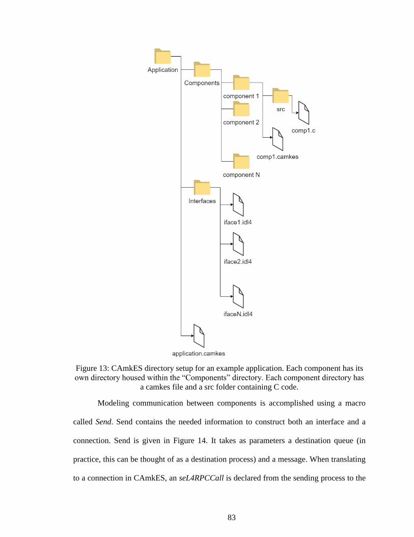
83
Figure 13: CAmkES directory setup for an example application. Each component has its
own directory housed within the “Components” directory. Each component directory has
a camkes file and a src folder containing C code.
Modeling communication between components is accomplished using a macro
called Send. Send contains the needed information to construct both an interface and a
connection. Send is given in Figure 14. It takes as parameters a destination queue (in
practice, this can be thought of as a destination process) and a message. When translating
to a connection in CAmkES, an seL4RPCCall is declared from the sending process to the

84
receiving process. Figure 15 shows Send calls that originate from Modtx and forward
messages to Crypto and Modchk, along with the corresponding connections created in the
CAmkES project.
macro send(dest, msg) begin \*print "sending to " \o dest; chan[dest] := Append(chan[dest], msg); end macro; macro receive(channel, msg) begin \*print channel \o " received msg"; await Len(chan[channel]) > 0; msg := Head(chan[channel]); chan[channel] := Tail(chan[channel]); end macro;
Figure 14: PlusCal definitions for Send and Receive macros
check2: send("messagecheck", [id|->msgid, text|->rxBuf, source|->"trustnet_in"]);
check3: send("sign", [id|->msgid, text|->rxBuf]);
/* Things coming out of the modtx component */
connection seL4RPCCall conn1(from modtx.modchk_iface,
to modchk.modchk_iface);
connection seL4RPCCall conn2(from modtx.crypto_iface,
to crypto.crypto_iface);
Figure 15: Send macros in TLA+ and their translations into CAmkES connections.
Declarations of seL4RPCCall connections from the Modtx component to the protocol
checking component (conn1) and the crypto component (conn2)
Finally, translating Send macros into interfaces can be tricky, as TLA+ is an
untyped specification language and CAmkES defines interfaces using the strongly typed
C programming language. There have been efforts to add a refinement type system to

85
TLA+ [138], but those were not used here. Instead, invariants were used to ensure
variables conformed to their proper encodings within TLA+, and the types were
translated manually into C. The Send macro example from Figure 15 is refreshed in
Figure 16 along with its translation into an interface.
check3: send("sign", [id|->msgid, text|->rxBuf]);
procedure CryptoIface {
void sign(in string rxBuf, in int msgid);
};
Figure 16: A Send macro in TLA+ and its translation to a CAmkES interface
Both components involved in the operation see their .camkes files modified to
reflect that the receiving process provides the interface and the sending process consumes
the interface. These modifications are seen in Figure 17.
check2: send("messagecheck", [id|->msgid, text|->rxBuf, source|->"trustnet_in"]);
check3: send("sign", [id|->msgid, text|->rxBuf]);
component Modtx {
control;
provides ModtxIface modtx_iface;
uses ModchkIface modchk_iface;
uses CryptoIface crypto_iface;
}
Figure 17: Translation of a PlusCal send macro to a CAmkES component definition
The steps for translating from TLA+ (PlusCal specifically) to CAmkES can be
written as follows:

86
1. Using the Send and Receive macros for inter-process communication, specify a system with
multiple processes that are well behaved (i.e. they do not modify global variables other than
through Send and Receive).
2. Create a CAmkES project with an empty directory structure
3. For each process:
a. Create a subdirectory structure with name matching the process label
b. Create a .idl4 interface file in the interfaces directory with name matching the process
label
4. For each process:
a. For each Send macro in the process:
i. Create a new interface declaration (if one does not already exist with this name
and parameters) in the sending process’s .idl4 file
ii. Within this interface declaration, create a C function prototype with:
1. return type void
2. parameters matching the field names in the second argument of the Send
macro and types as specified in the invariants
iii. Within the .camkes file for the sending component
1. Insert “uses *receiving_component_interface*”
iv. Within the .camkes file for the receiving component
1. Insert “provides *receiving_component_interface*”
v. Create a new seL4RPCCall connection from sending process to receiving
interface in the root .camkes file
The final step is to fill the components with C code that implements the behavior
specified in the TLA+ model. This cannot be automated in this context as TLA+ is
designed for reasoning on the what tasks a system accomplishes, not how the system
accomplishes those tasks. TLA+ specifications provide good guidance on how to
implement the C code within the components, but this is a manual task.
3.7 Security Preprocessor as Previously Designed
In 2012, Hieb, Graham, Schreiver, and Moss presented a design and prototype for
a Field Device Secuity Preprocessor (FD-SPP) to create and protect a perimeter around
field devices located at remote stations in a SCADA network [130]. The work builds
from previous papers describing a security hardened remote terminal unit (RTU) built

87
from the ground up with security as a focus [139]. This hardened RTU logically isolates
security-critical code such as cryptographic services, access control enforcement, and the
policy decision point from each other and from the network interfaces. Feedback on this
work led to pulling the security processing steps out of the RTU and into a separate
device to minimize impact of installing such features into an existing network. The FD-
SPP is an embedded control systems security device to which the proposed formal
verification techniques could be applied.
The FD-SPP can act as a bump-in-the-wire configuration to allow a simple
installation of two devices at either end of a communication line. Installation should be as
simple as plugging them in and turning them on – no other devices on either end of the
network would need to be bothered. Additionally, the FD-SPP should not add any new
attack vectors to the network. The layered security of isolated components and
cryptographic mechanisms would reduce the attack surface and make compromising the
application very difficult. Figure 18 simplifies a SCADA network to the pieces relevant
to this discussion. A Human-Machine Interface (HMI) or a Programmable Logic
Controller (PLC) in the control center would communicate through some medium to an
RTU at a remote substation. Figure 19 illustrates how a FD-SPP would change the
network diagram. One FD-SPP device would need to be placed in the control center right
after the HMI, and a second device would need to be place in the substation right before
the RTU. Both devices encapsulate messages going out of their respective zones, and
both devices decapsulate messages coming into their prospective zones.

88
Figure 18: Connection from the control center (left) to RTU (right) on a typical SCADA
network
Figure 19: Connection from the control center to RTU with the FD-SPP installed
The FD-SPP offered in 2012 was built on top of an unverified but high
assurance microkernel. Hieb et al. designed the FD-SPP to operate with three
components, or cells, each with their own responsibilities and a limited ability to affect
one another. Threads in each cell can communicate with each other normally, but
communication between cells in different threads is strictly determined at compile time.
The cell configuration can be seen in Figure 20. The three cells act in sequence, with
messages moving through all three for processing before reaching the other side. The two
outer cells interface with the control network (the prototype utilized a serial port, but this
was not necessary). The inner cell acted as the security controller and housed the access
control and cryptographic logic. This configuration had the added benefit of protecting
the security critical process from the outside world. An attack on this device would need
to bypass at least one networking cell before attempting to compromise the security
properties.

89
Figure 20: FD-SPP architecture
The FD-SPP as proposed offered access control and authentication capabilities to
a Modbus RTU network. Modbus, both Modbus ASCII and Modbus RTU, are missing
any sort of security mechanism in their specification. As seen in [29], [105], both
mechanisms could be added with overhead small enough to fit the timing constraints in a
large portion of SCADA networks. Authentication would be provided through use of a
pre-shared key for each user and a challenge-response protocol similar to [42]. The
Modbus protocol would be extended to add the required function codes to allow for a
challenge-response: a Request code, a Challenge code, and a Response code. A Request
message would flow to the field device containing a user ID. The field device would
generate a nonce and send it back as a challenge. Finally, the control center device would
hash the nonce with the user’s secret using SHA-256 and append the result to the original
Modbus packet. The field device would also perform the hash with the user’s secret and
ensure the calculated hash and the response hash are the same. If they are equal, the

90
Modbus message can pass through to the RTU. The response from the RTU can pass
through the FD-SPP and travel back to the control center without trouble.
Hieb et al. also proposed a Role-Based Access Control (RBAC) mechanism that
would operate within the security cell. User roles would be mapped to a set of allowable
opcodes and users would be assigned user roles. During the challenge-response process,
the user would be authenticated, then checked against an access control matrix. A low-
level operator might have permission to read the control signals, but an attempt to change
control logic would be denied. The difficulty of managing roles and complexity of
management led this feature to be discarded in later designs.
The FD-SPP was developed for the OKL4 kernel, a precursor to seL4, and as such
is already separated into critical components. The OKL4 kernel limited designers to up to
three components per system, but seL4 removes this limitation. The newly designed
architecture should add a fourth component to separate the critical protocol checking
code from the critical cryptographic code and perhaps have these components work in
parallel. Stated very informally, the desired properties of the holistic system include:
1 Isolation between components such that a compromised component cannot affect
any others
2 Only proper messages can be allowed to pass through – no malformed messages
3 Only properly formed messages can originate from the device
4 Every message is properly authenticated
5 Every message is protected from tampering
6 All legitimate messages do eventually pass through (except in the case of denial
of service)
3.8 Summary
Adding security to an existing control systems network requires careful
considerations to reduce downtime, reduce added latency, and reduce added failure

91
points. A bump-in-the-wire security preprocessor built atop a high-assurance microkernel
like seL4 might reduce the impact of added security enough to be palatable to asset
owners. This chapter proposed a development cycle for engineering high-assurance
embedded systems with formally described and verified security and safety properties.
An informal design of an embedded system can be formalized and verified using TLA+.
The TLA+ specification can be used to define an architecture in CAmkES. Finally, the
components in the CAmkES architecture can be populated with the C implementations of
their algorithms.

92
CHAPTER IV
MODELING A BUMP-IN-THE-WIRE SECURITY PREPROCESSOR
4.1 Introduction
Formally specifying a system must start with choosing the properties the system
must possess. Once the properties are chosen, checking those properties informs the
design of the specification. The level of abstraction depends on what pieces of the system
are relevant to the properties. Choosing which pieces of the system that can be modeled
separately depend on how their interactions affect the properties. Metadata like unique
message identifiers may need to be included in the model that may not exist in the real
system to keep track of the moving parts. The contributions presented in this chapter are
the formal specifications written in TLA+ for each piece of a field device security
preprocessor that needed to be modeled to capture these desired properties:
1 Isolation between components such that a compromised component cannot affect
any others
2 Only proper messages can be allowed to pass through – no malformed messages
3 Only properly formed messages can originate from the device
4 Every message is properly authenticated
5 Every message is protected from tampering
6 All legitimate messages do eventually pass through (except in the case of denial
of service)
None of these properties can be directly described in TLA+. Each thread defined
in TLA+ in this chapter has subgoals, or smaller properties that can be proven and then
used in conjunction to achieve the larger properties. This chapter will first lay out any

93
assumptions made when formulating the models, then go into detail on each of the
models and their respective properties, and finally explain some novel helper functions
and formal definitions that aided in the development.
4.2 Assumptions
Every security mechanism, verified or otherwise, works on a set of assumptions
that if violated will compromise the guarantees claimed by the mechanism. An
assumption can be as simple as “a user’s password will only be known by that user” in a
corporate network environment. Beyond showing proofs of certain properties,
verification forces a designer to rigorously define any assumptions made by the system so
they can be addressed in the implementation and risk assessment. When installing a
security mechanism into an existing system, care must be taken to ensure all assumptions
made by the mechanism are met. Formalizing a design produces a list of assumptions as a
by-product that can be included in any documentation to future engineers and operators.
The modeling work presented here works from certain assumptions based on two
limitations: the scope of the research, and resources available. The first limitation
involves limiting the scope of the research to just the FD-SPP software and architecture.
The hardware is assumed to be correct. Techniques for developing reliable hardware have
come a long way, but some level of trust is still needed, specifically on hardware that
seL4 supports. The second assumption in this category is that the kernel is correct. Use of
seL4 allows this assumption to be removed in practice, but the kernel is not modeled in
TLA+. The third assumption is that the trusted parts of the control network are behaving
properly. The system, and therefore the model, is not acting as an application firewall and
deciding whether the valid and authentic Modbus messages are appropriate for the

94
control logic. A malicious operator acting on the trusted network could send destructive
messages through the system if they are properly formed - the destruction would
potentially affect the cyber-physical portion of the network and ideally leave the network
nodes unharmed. Finally, this research recognizes the network at large is still vulnerable
to denial of service attacks whether from the trusted or untrusted network. Enough
malformed messages could be introduced to the untrusted network to prevent valid
messages from getting through. The system being modeled does not attempt to address
this attack vector.
The second category of assumptions is made to reduce the size of the model and
allow a higher level of abstraction to reduce the resource strain on the researcher and the
model checker. Only the behavior of each component and system is modeled. How the
implementation achieves that behavior is left to future work. The algorithm for each
action is modeled, but the code that would run on a live system is assumed to be correct.
Secondly, the secret is assumed to be secret. An attacker that holds the secret can break
the system. Additionally, each component assumes data from the other components is
correct. While proof is given that networking components can only send well-formed
messages out to the networks, they are capable of sending invalid messages if they
receive invalid messages from the inner components. Finally, the cryptographic
algorithms are assumed to hold their claimed properties. This assumption can be eased
for HMAC through use of the verified cryptographic code described in [87], and removed
through use of CompCert as the compiler. There are currently no proofs that SHA-256 is
“secure”. The best that can be offered are heuristic arguments.

95
4.3 Formal TLA+ Specifications for Components and Properties
Formalizing a design in a modeling language like TLA+ requires deciding what is
important aspects of a system are important to capture in the model and what aspects are
unimportant and can be abstracted to ease the modeling effort. As model checking can
quickly run into the state explosion problem, care must be taken to ensure that the system
is described sufficiently to be of value, while not getting so detailed as to render checking
infeasible. The system described in the remaining sections of this chapter and seen in
[140] is modeled component by component, then as a single system. Memory
management and communication between the components is abstracted.
Everything should be made as simple as possible, but not simpler.
– Albert Einstein
4.3.1 Modeling the Trusted Network Component
The trusted network component is separated into two processes (processes can be
thought of as threads), receiving messages from the trusted network and sending
messages on the trusted network. The receive process, called trustnet_in, is designed to
poll a serial port for input, so its logic is placed within a while loop that executes while
there are messages to be processed. The algorithm for this thread is a basic loop,
visualized in, that will read a byte at a time from an incoming message and place it into a
buffer. After processing is completed, the buffers are cleared and the thread starts again
from the top. The more complicated parts come with the desired property that only well-
formed Modbus messages reach the inner components. To achieve this, the logic checks
each byte of input for “:”, indicating the start of a Modbus ASCII message. If a new
Modbus message is started before the previous one is finished, the previous message is
discarded. Whenever a “:” is received, the contents of the buffer are flushed and the “:” is

96
placed at the start of the empty buffer. Similarly, if the buffer is full despite not receiving
a complete message, its contents are discarded, and the logic waits for a new “:”.
Secondly, the logic checks for the termination of Modbus messages. Modbus ASCII
messages end with the two-byte sequence “\r\n”. When this sequence is detected, this
thread generates an object containing the message, a generated message ID, and
“trustnet_in” and places the object into the signing queue of Crypto. A similar object is
created with just the message and ID and placed in the queue of Modchk.
The desired behavior of the Trustnet_in thread is that it accepts only and all well-
formed Modbus, forwards only well-formed Modbus, forwards the Modbus to both inner
components in the same atomic step, forwards a single message exactly once, and doesn’t
overflow any buffers. The properties that need to be proven for this thread are seen in
Table 10. The formalized property can be seen in the middle and the informal description
can be seen on the right. There are several variables and custom operators in the
formalized properties that the reader might like to familiarize themselves with in Table
11 before examining the properties themselves.

97
Figure 21: Flowchart for Trustnet_in thread

98
Table 10: The desired properties of the Trustnet_in thread
Name Formalized Property in TLA+ Informal Property
SAFE1 𝐿𝑒𝑛(𝑟𝑥𝐵𝑢𝑓) ≤ 𝑀𝐴𝑋𝑀𝑂𝐷𝐵𝑈𝑆𝑆𝐼𝑍𝐸 receive buffer never
overflows
SAFE2 ∧ ∀ 𝑥 ∈ 𝑅𝑎𝑛𝑔𝑒(𝑠𝑖𝑔𝑛𝐵𝑢𝑓𝑓𝑒𝑟) ∶ 𝐿𝑒𝑛(𝑥. 𝑡𝑒𝑥𝑡) ≤ 𝑀𝐴𝑋𝑀𝑂𝐷𝐵𝑈𝑆𝑆𝐼𝑍𝐸 ∧ ∀ 𝑥 ∈ 𝑅𝑎𝑛𝑔𝑒(𝑚𝑜𝑑𝑐ℎ𝑘𝐵𝑢𝑓𝑓𝑒𝑟) ∶ 𝐿𝑒𝑛(𝑥. 𝑡𝑒𝑥𝑡)
≤ 𝑀𝐴𝑋𝑀𝑂𝐷𝐵𝑈𝑆𝑆𝐼𝑍𝐸
sending buffer never
overflows
SAFE3 𝐿𝑒𝑛(𝑙𝑎𝑠𝑡2) < 3 last2 buffer never
overflows
SAFE4 ∧ ∀𝑥 ∈ 𝑅𝑎𝑛𝑔𝑒(𝑠𝑖𝑔𝑛𝐵𝑢𝑓𝑓𝑒𝑟) ∶ 𝐼𝑠𝑊𝑒𝑙𝑙𝐹𝑜𝑟𝑚𝑒𝑑𝑀𝑜𝑑𝑏𝑢𝑠(𝑥. 𝑡𝑒𝑥𝑡) ∧ ∀𝑥 ∈ 𝑅𝑎𝑛𝑔𝑒(𝑚𝑜𝑑𝑐ℎ𝑘𝐵𝑢𝑓𝑓𝑒𝑟) ∶ 𝐼𝑠𝑊𝑒𝑙𝑙𝐹𝑜𝑟𝑚𝑒𝑑𝑀𝑜𝑑𝑏𝑢𝑠(𝑥. 𝑡𝑒𝑥𝑡)
only well-formed
Modbus gets
forwarded
SAFE5 ∧ ∀𝑥 ∈ 𝑅𝑎𝑛𝑔𝑒(𝑠𝑖𝑔𝑛𝐵𝑢𝑓𝑓𝑒𝑟) ∶ 𝐶𝑎𝑟𝑑𝑖𝑛𝑎𝑙𝑖𝑡𝑦({𝑦 ∈ 𝑅𝑎𝑛𝑔𝑒(𝑠𝑖𝑔𝑛𝐵𝑢𝑓𝑓𝑒𝑟) ∶ 𝑥. 𝑖𝑑 = 𝑦. 𝑖𝑑}) = 1
∧ ∀𝑥 ∈ 𝑅𝑎𝑛𝑔𝑒(𝑚𝑜𝑑𝑐ℎ𝑘𝐵𝑢𝑓𝑓𝑒𝑟) ∶ 𝐶𝑎𝑟𝑑𝑖𝑛𝑎𝑙𝑖𝑡𝑦({𝑦 ∈ 𝑅𝑎𝑛𝑔𝑒(𝑚𝑜𝑑𝑐ℎ𝑘𝐵𝑢𝑓𝑓𝑒𝑟) ∶ 𝑥. 𝑖𝑑 = 𝑦. 𝑖𝑑}) =1
each message that is
forwarded has a
unique message id*
SAFE6 ∧ ∀𝑥 ∈ 𝑅𝑎𝑛𝑔𝑒(𝑠𝑖𝑔𝑛𝐵𝑢𝑓𝑓𝑒𝑟) ∶ ∃𝑦 ∈ 𝑅𝑎𝑛𝑔𝑒(𝑚𝑜𝑑𝑐ℎ𝑘𝐵𝑢𝑓𝑓𝑒𝑟) ∶ 𝑥. 𝑖𝑑 = 𝑦. 𝑖𝑑 ∧ ∀𝑥 ∈ 𝑅𝑎𝑛𝑔𝑒(𝑚𝑜𝑑𝑐ℎ𝑘𝐵𝑢𝑓𝑓𝑒𝑟) ∶ ∃𝑦 ∈ 𝑅𝑎𝑛𝑔𝑒(𝑠𝑖𝑔𝑛𝐵𝑢𝑓𝑓𝑒𝑟) ∶ 𝑥. 𝑖𝑑 = 𝑦. 𝑖𝑑
well-formed messages
get sent to both inner
components
SAFE7 ¬(𝑟𝑥𝐵𝑢𝑓 = ⟨⟩) ⇒ 𝐻𝑒𝑎𝑑(𝑟𝑥𝐵𝑢𝑓) = ": " rxBuf is either empty
or starts with ":"
LIVE1 𝐼𝑠𝑊𝑒𝑙𝑙𝑓𝑜𝑟𝑚𝑒𝑑𝑀𝑜𝑑𝑏𝑢𝑠(𝑚𝑠𝑔) ⇝
∃𝑥 ∈ 𝑟𝑎𝑛𝑔𝑒(𝑠𝑖𝑔𝑛𝐵𝑢𝑓𝑓𝑒𝑟) ∶ 𝑥. 𝑡𝑒𝑥𝑡 = 𝑚𝑠𝑔 if the message is well-
formed then it gets
sent. This is weaker
than desired as it only
shows some message
exists, not necessarily
the same message.
LIVE2 ◇(𝑖𝑛𝑐𝑜𝑚𝑖𝑛𝑔𝑀𝑒𝑠𝑠𝑎𝑔𝑒𝑠 = ⟨⟩) all messages are
processed
LIVE3 𝑙𝑎𝑠𝑡2 = ⟨"\𝑟", "\𝑛"⟩ ⇝ 𝑙𝑎𝑠𝑡2 = ⟨0,0⟩ last2 buffer gets reset
after each well-formed
message
Formalized properties are usually not simple and can take some effort to
understand. The property SAFE2, given again in Equation (6), is a conjunction of two
statements. Each line in the conjunction starts with ∧, meaning “and”. These two
statements make use of a local symbol 𝑥. The first half of the first statement, the portion
before the colon, can be read as “For all 𝑥, where 𝑥 is an element of the set signBuffer”.
SignBuffer is an ordered sequence of messages that are meant to be sent to the Crypto

99
Table 11: TLA+ symbols used in the property definitions for trustnet_out
Symbol Description
rxBuf A buffer that holds the bytes that are received from the
network. This is a sequence.
Range() 𝑅𝑎𝑛𝑔𝑒(𝑇) ≜ {𝑇[𝑥] ∈ 𝐷𝑂𝑀𝐴𝐼𝑁 𝑇}3
signBuffer, modchkBuffer The buffers that hold messages “sent” to the respective inner
components. These are an abstraction as the full model
implements the message passing.
last2 A sequence for keeping track of the last two characters in
rxBuf. For finding “\r\n”
IsWellformedModbus() Is true if the message length, starting, and ending characters
are all correct.
msg The raw Modbus message being processed
incomingMessages The set of messages that will be received
component. Note that SignBuffer does not contain raw Modbus. It holds message
structures with fields for the raw Modbus, the message ID, and other piece of metadata
that might need to be forwarded to a component. Following the colon, Len() returns the
length of a sequence. Text is the field within the message structure that contains the raw
Modbus, so the right of the colon is ensuring the length of the raw Modbus contained in
𝑥. 𝑡𝑒𝑥𝑡 is less than or equal to the maximum size of a Modbus packet. The second line of
the equation is the same property stated for the modchkBuffer that holds messages to be
sent to the Modchk component. These properties are invariants; they are checked to be
true in every state that is generated.
∧ ∀ x ∈ Range(signBuffer) ∶ Len(x. text) ≤ MAXMODBUSSIZE
∧ ∀ x ∈ Range(modchkBuffer) ∶ Len(x. text) ≤ MAXMODBUSSIZE (6)
Properties SAFE2 and SAFE4-6 are two properties ANDed to which the logical
AND operator is applied as fulfillment of the general property requires checking the same
3 In TLA+, as in mathematics, what a programmer calls a function is an array. The domain of the
function is the set of numbers over which the function is defined. The range of the function is the set of
values the function produces when a number from its domain is given as input. In programming terms,
Range(T) returns the elements of an array in an unordered set.

100
thing for two different buffers. SAFE5 shows that the ID sent is unique, but this property
likely will need to be adjusted upon translation to real code as the implementation for a
unique identifier will be limited to finite numbers and risks repeating. This property
might be relaxed to an assumption that the ID implementation has a low repeat
probability.
Trustnet_out
The thread responsible for collating messages from the inner components and
sending them out to the trusted network is called trustnet_out and can be seen in Figure
22. This thread works from a FIFO queue that the inner components populate.
Trustnet_out waits until a message n is placed in its queue, then checks if a message with
the same ID, message m, has already been received. Checking for the existence of
message m involves filtering a set4 for a message with the same ID. If the companion
message has not been received, then n is placed in the set of received messages and the
loop repeats. If it has, and one or both messages have been marked as invalid, then both
messages are discarded and the loop repeats. If both messages have been marked valid by
the inner components, the raw Modbus is placed in the set of valid messages that have
successfully traversed the device, finished_trustnet. Finished_trustenet abstractly
represents the raw Modbus that has been printed to the serial port. The properties that
need to be proven for this thread are seen in Table 12. The formalized property can be
seen on the left and the informal description can be seen on the right.
4 A set in TLA+ is the equivalent of a set in mathematics; it is unordered and potentially infinite.
Using a set in the specification abstracts away the specific data structure chosen for the C code. The only
stipulation is the method of the chosen data structure for finding an element must behave equivalently to
filtering a set.

101
Table 12: The desired properties of the Trustnet_out thread
Name Formalized Property in TLA+ Informal Property
SAFE1 ∧ ∀𝑥 ∈ 𝑅𝑎𝑛𝑔𝑒(𝑠𝑒𝑟𝑖𝑎𝑙𝑝𝑜𝑟𝑡) ∶ ∃𝑦 ∈ 𝑅𝑎𝑛𝑔𝑒(𝑚𝑒𝑡𝑎𝑠𝑒𝑟𝑖𝑎𝑙𝑝𝑜𝑟𝑡) ∶ 𝑦. 𝑡𝑒𝑥𝑡 = 𝑥 ∧ ∀𝑦 ∈ 𝑅𝑎𝑛𝑔𝑒(𝑚𝑒𝑡𝑎𝑠𝑒𝑟𝑖𝑎𝑙𝑝𝑜𝑟𝑡) ∶ ∃𝑥 ∈ 𝑅𝑎𝑛𝑔𝑒(𝑠𝑒𝑟𝑖𝑎𝑙𝑝𝑜𝑟𝑡) ∶ 𝑥 = 𝑦. 𝑡𝑒𝑥𝑡
items on the serial
port and the
metaserialport are
the same (weakly,
this checks for the
existance of a
message but its not
1-1 mapping)
SAFE2 ∀𝑥 ∈ 𝑅𝑎𝑛𝑔𝑒(𝑚𝑒𝑡𝑎𝑠𝑒𝑟𝑖𝑎𝑙𝑝𝑜𝑟𝑡): ∧ (∃𝑦 ∈ 𝑅𝑎𝑛𝑔𝑒(𝑀𝑒𝑠𝑠𝑎𝑔𝑒𝑠𝐹𝑟𝑜𝑚𝐼𝑛𝑛𝑒𝑟𝐶𝑒𝑙𝑙𝑠) ∶ 𝑥. 𝑖𝑑 = 𝑦. 𝑖𝑑 ∧ 𝑦. 𝑖𝑠𝑣𝑎𝑙𝑖𝑑 ∧ 𝑦. 𝑠𝑜𝑢𝑟𝑐𝑒 = "𝑚𝑜𝑑𝑐ℎ𝑘"
∧ (∃𝑦 ∈ 𝑅𝑎𝑛𝑔𝑒(𝑀𝑒𝑠𝑠𝑎𝑔𝑒𝑠𝐹𝑟𝑜𝑚𝐼𝑛𝑛𝑒𝑟𝐶𝑒𝑙𝑙𝑠) ∶ 𝑥. 𝑖𝑑 = 𝑦. 𝑖𝑑 ∧ 𝑦. 𝑖𝑠𝑉𝑎𝑙𝑖𝑑 ∧ 𝑦. 𝑠𝑜𝑢𝑟𝑐𝑒 = "𝑣𝑒𝑟𝑖𝑓𝑦"
Only prints if both
inner components
say its valid
SAFE3 𝐿𝑒𝑛(𝑡𝑥𝐵𝑢𝑓) < 𝑀𝐴𝑋𝑀𝑂𝐷𝐵𝑈𝑆𝑆𝐼𝑍𝐸 sending buffer never
overflows
SAFE4 ∀𝑥 ∈ 𝑅𝑎𝑛𝑔𝑒(𝑠𝑒𝑟𝑖𝑎𝑙𝑝𝑜𝑟𝑡) ∶ ∃𝑦 ∈ 𝑅𝑎𝑛𝑔𝑒(𝑀𝑒𝑠𝑠𝑎𝑔𝑒𝑠𝐹𝑟𝑜𝑚𝐼𝑛𝑛𝑒𝑟𝐶𝑒𝑙𝑙𝑠) ∶ 𝑥 = 𝑦. 𝑡𝑒𝑥𝑡
only valid Modbus
gets printed (this
module assumes
valid Modbus is
received from both
inner components
LIVE1 ∀𝑥 ∈ 𝑅𝑎𝑛𝑔𝑒(𝑀𝑒𝑠𝑠𝑎𝑔𝑒𝑠𝐹𝑟𝑜𝑚𝐼𝑛𝑛𝑒𝑟𝐶𝑒𝑙𝑙𝑠) ∶ 𝑥 ∈ 𝑣𝑎𝑙𝑖𝑑𝑀𝑒𝑠𝑠𝑎𝑔𝑒𝑠 ∧ 𝑥. 𝑖𝑑 = 𝑚𝑠𝑔. 𝑖𝑑
⇝ 𝑥 ∉ 𝑣𝑎𝑙𝑖𝑑𝑀𝑒𝑠𝑠𝑎𝑔𝑒𝑠
Each message that
gets its companion
message is sent or
discarded
LIVE2 ∀𝑥 ∈ 𝑅𝑎𝑛𝑔𝑒(𝑀𝑒𝑠𝑠𝑎𝑔𝑒𝑠𝐹𝑟𝑜𝑚𝐼𝑛𝑛𝑒𝑟𝐶𝑒𝑙𝑙𝑠) ∶ 𝑚𝑠𝑔 = 𝑥 ∧ 𝑥. 𝑖𝑠𝑉𝑎𝑙𝑖𝑑 ∧ (∃𝑦 ∈ 𝑣𝑎𝑙𝑖𝑑𝑀𝑒𝑠𝑠𝑎𝑔𝑒𝑠 ∶ 𝑦. 𝑖𝑑 = 𝑥. 𝑖𝑑 ∧ 𝑦. 𝑖𝑠𝑉𝑎𝑙𝑖𝑑 ∧ 𝑦. 𝑠𝑜𝑢𝑟𝑐𝑒 ≠ 𝑥. 𝑠𝑜𝑢𝑟𝑐𝑒) ⇝ ∃𝑧 ∈ 𝑅𝑎𝑛𝑔𝑒(𝑚𝑒𝑡𝑎𝑠𝑒𝑟𝑖𝑎𝑙𝑝𝑜𝑟𝑡) ∶ 𝑧. 𝑖𝑑 = 𝑥. 𝑖𝑑
valid messages are
eventually sent
LIVE3 ∀𝑥 ∈ 𝑅𝑎𝑛𝑔𝑒(𝑀𝑒𝑠𝑠𝑎𝑔𝑒𝑠𝐹𝑟𝑜𝑚𝐼𝑛𝑛𝑒𝑟𝐶𝑒𝑙𝑙𝑠) ∶ 𝑇𝑅𝑈𝐸 ⇒ ◇(∃𝑦 ∈ 𝑣𝑎𝑙𝑖𝑑𝑀𝑒𝑠𝑠𝑎𝑔𝑒𝑠 ∶ 𝑦. 𝑖𝑑 = 𝑥. 𝑖𝑑)
all messages are
eventually processed
An interesting note with LIVE1 is that it does not ensure that all messages that are
received are sent out through the serial port. The Trustnet_in and Untrustnet_in modules
can guarantee that messages they receive (provided the messages are valid) pass through
to the inner components, but this component and Untrustnet_out rely on messages from
two sources: Modchk and Crypto. These two sources are not defined in this TLA+
module, so no properties can be formulated based on their behavior. As such, the

102
strongest liveness property that can be checked is that if message 𝑥with id 𝑖 is received
from one inner component, message 𝑦 with id 𝑖 is received from the other inner
component, then those messages are acted upon (sent or discarded) then removed from
the set of waiting messages. LIVE1 is restated formally in Equation 7. The variable
validMessages is a misnomer as it does not contain just valid messages, but all messages
that have been received from the inner components and are awaiting their corresponding
message from the opposite component. It is a waiting room for unconsumed messages. A
message could be stuck in this waiting room forever and the Trustnet_out specification
would still be valid.
∀x ∈ Range(MessagesFromInnerCells) ∶
x ∈ validMessages ∧ x. id = msg. id
⇝ x ∉ validMessages
(7)
While TLA+ is very expressive, there are many expressions that are valid in
TLA+ but which the TLC model checker refuses to evaluate. TLA+ uses mathematical
notation, but in this dissertation the expressions are often describing actions rather than
strictly equations. Actions relate to a state and a successor state, so certain variables at
given states might not have been assigned at the time TLC tries to evaluate them. While
working through the formalization of properties for this research, certain properties like
LIVE1 were repeatedly reworked to account for these limitations. An earlier form of
LIVE1 is given in Equation (8). This version is accepted by the semantics of TLA+,
however in the initial state and any next-state computed from the initial state,
validMessages has no value. The expression 𝑥 ∈ 𝑣𝑎𝑙𝑖𝑑𝑀𝑒𝑠𝑠𝑎𝑔𝑒𝑠 make sense
mathematically, but TLC is unable to check it. To work around this, the possible values
of x were defined in the constant MessagesFromInnerCells seen in Equation (7) so the
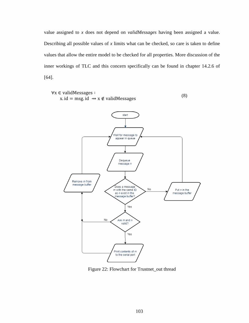
103
value assigned to x does not depend on validMessages having been assigned a value.
Describing all possible values of x limits what can be checked, so care is taken to define
values that allow the entire model to be checked for all properties. More discussion of the
inner workings of TLC and this concern specifically can be found in chapter 14.2.6 of
[64].
∀x ∈ validMessages ∶ x. id = msg. id ⇝ x ∉ validMessages
(8)
Figure 22: Flowchart for Trustnet_out thread

104
4.3.2 Modeling the Untrusted Network Component
The untrusted networking component is similar to the trusted network component.
As with the opposite network component design, the untrusted network component is
separated into two processes: receiving messages from the untrusted network and sending
messages on the untrusted network. The receiving process, called untrustnet_in, is
designed to poll the serial port for input, so its logic is placed within a while loop that
executes while there are messages to be processed. The algorithm for this thread is a
basic loop, visualized in Figure 23, that will read a byte at a time from an incoming
message and place it into a buffer. After processing is completed, the buffers are cleared
and the thread starts again from the top. The more complicated parts come with the
desired property that only well-formed Modbus messages reach the inner components. To
achieve this, the logic checks each byte of input for “!”, indicating the start of an
encapsulated message. If a new encapsulated message is started before the previous one
is finished, the previous message is discarded. Whenever a “!” is received, the contents of
the buffer are flushed and the “!” is placed at the start of the empty buffer. Similarly, if
the buffer is full despite not receiving a complete message, its contents are discarded, and
the logic waits for a new “!”. Secondly, the logic checks for the start of a well-formed
Modbus message 64 characters later, starting after the HMAC. Next, the logic looks for
the termination of a Modbus message. Encapsulated messages terminate with Modbus,
and Modbus ASCII messages end with the two-byte sequence “\r\n”. When this sequence
is detected, this thread generates a structure containing the message, a generated message
ID, and “trustnet_in” and places the object into the signing queue of Crypto. A similar
structure is created with just the message and ID and placed in the queue of Modchk.

105
Figure 23: Flowchart for untrustnet_in thread
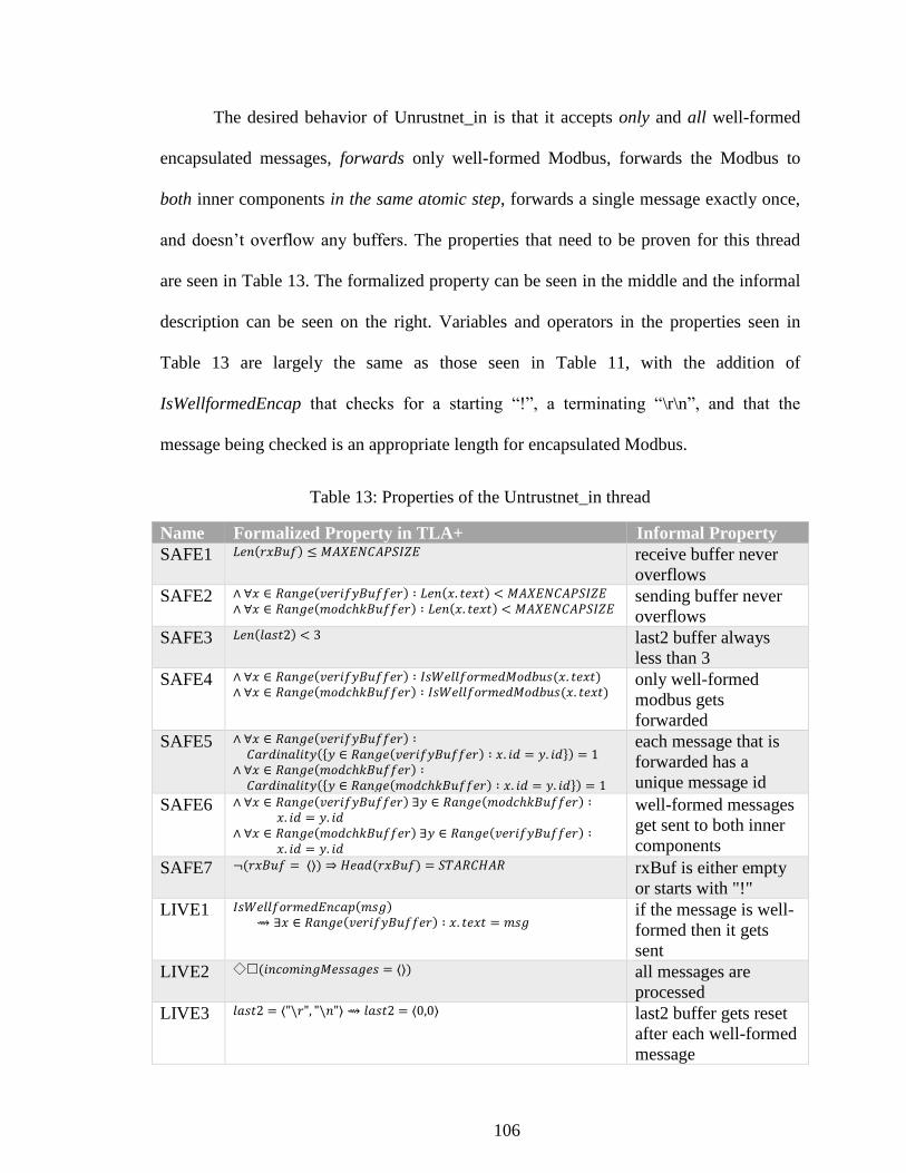
106
The desired behavior of Unrustnet_in is that it accepts only and all well-formed
encapsulated messages, forwards only well-formed Modbus, forwards the Modbus to
both inner components in the same atomic step, forwards a single message exactly once,
and doesn’t overflow any buffers. The properties that need to be proven for this thread
are seen in Table 13. The formalized property can be seen in the middle and the informal
description can be seen on the right. Variables and operators in the properties seen in
Table 13 are largely the same as those seen in Table 11, with the addition of
IsWellformedEncap that checks for a starting “!”, a terminating “\r\n”, and that the
message being checked is an appropriate length for encapsulated Modbus.
Table 13: Properties of the Untrustnet_in thread
Name Formalized Property in TLA+ Informal Property
SAFE1 𝐿𝑒𝑛(𝑟𝑥𝐵𝑢𝑓) ≤ 𝑀𝐴𝑋𝐸𝑁𝐶𝐴𝑃𝑆𝐼𝑍𝐸 receive buffer never
overflows
SAFE2 ∧ ∀𝑥 ∈ 𝑅𝑎𝑛𝑔𝑒(𝑣𝑒𝑟𝑖𝑓𝑦𝐵𝑢𝑓𝑓𝑒𝑟) ∶ 𝐿𝑒𝑛(𝑥. 𝑡𝑒𝑥𝑡) < 𝑀𝐴𝑋𝐸𝑁𝐶𝐴𝑃𝑆𝐼𝑍𝐸 ∧ ∀𝑥 ∈ 𝑅𝑎𝑛𝑔𝑒(𝑚𝑜𝑑𝑐ℎ𝑘𝐵𝑢𝑓𝑓𝑒𝑟) ∶ 𝐿𝑒𝑛(𝑥. 𝑡𝑒𝑥𝑡) < 𝑀𝐴𝑋𝐸𝑁𝐶𝐴𝑃𝑆𝐼𝑍𝐸
sending buffer never
overflows
SAFE3 𝐿𝑒𝑛(𝑙𝑎𝑠𝑡2) < 3 last2 buffer always
less than 3
SAFE4 ∧ ∀𝑥 ∈ 𝑅𝑎𝑛𝑔𝑒(𝑣𝑒𝑟𝑖𝑓𝑦𝐵𝑢𝑓𝑓𝑒𝑟) ∶ 𝐼𝑠𝑊𝑒𝑙𝑙𝑓𝑜𝑟𝑚𝑒𝑑𝑀𝑜𝑑𝑏𝑢𝑠(𝑥. 𝑡𝑒𝑥𝑡)
∧ ∀𝑥 ∈ 𝑅𝑎𝑛𝑔𝑒(𝑚𝑜𝑑𝑐ℎ𝑘𝐵𝑢𝑓𝑓𝑒𝑟) ∶ 𝐼𝑠𝑊𝑒𝑙𝑙𝑓𝑜𝑟𝑚𝑒𝑑𝑀𝑜𝑑𝑏𝑢𝑠(𝑥. 𝑡𝑒𝑥𝑡) only well-formed
modbus gets
forwarded
SAFE5 ∧ ∀𝑥 ∈ 𝑅𝑎𝑛𝑔𝑒(𝑣𝑒𝑟𝑖𝑓𝑦𝐵𝑢𝑓𝑓𝑒𝑟) ∶ 𝐶𝑎𝑟𝑑𝑖𝑛𝑎𝑙𝑖𝑡𝑦({𝑦 ∈ 𝑅𝑎𝑛𝑔𝑒(𝑣𝑒𝑟𝑖𝑓𝑦𝐵𝑢𝑓𝑓𝑒𝑟) ∶ 𝑥. 𝑖𝑑 = 𝑦. 𝑖𝑑}) = 1
∧ ∀𝑥 ∈ 𝑅𝑎𝑛𝑔𝑒(𝑚𝑜𝑑𝑐ℎ𝑘𝐵𝑢𝑓𝑓𝑒𝑟) ∶ 𝐶𝑎𝑟𝑑𝑖𝑛𝑎𝑙𝑖𝑡𝑦({𝑦 ∈ 𝑅𝑎𝑛𝑔𝑒(𝑚𝑜𝑑𝑐ℎ𝑘𝐵𝑢𝑓𝑓𝑒𝑟) ∶ 𝑥. 𝑖𝑑 = 𝑦. 𝑖𝑑}) = 1
each message that is
forwarded has a
unique message id
SAFE6 ∧ ∀𝑥 ∈ 𝑅𝑎𝑛𝑔𝑒(𝑣𝑒𝑟𝑖𝑓𝑦𝐵𝑢𝑓𝑓𝑒𝑟) ∃𝑦 ∈ 𝑅𝑎𝑛𝑔𝑒(𝑚𝑜𝑑𝑐ℎ𝑘𝐵𝑢𝑓𝑓𝑒𝑟) ∶ 𝑥. 𝑖𝑑 = 𝑦. 𝑖𝑑
∧ ∀𝑥 ∈ 𝑅𝑎𝑛𝑔𝑒(𝑚𝑜𝑑𝑐ℎ𝑘𝐵𝑢𝑓𝑓𝑒𝑟) ∃𝑦 ∈ 𝑅𝑎𝑛𝑔𝑒(𝑣𝑒𝑟𝑖𝑓𝑦𝐵𝑢𝑓𝑓𝑒𝑟) ∶ 𝑥. 𝑖𝑑 = 𝑦. 𝑖𝑑
well-formed messages
get sent to both inner
components
SAFE7 ¬(𝑟𝑥𝐵𝑢𝑓 = ⟨⟩) ⇒ 𝐻𝑒𝑎𝑑(𝑟𝑥𝐵𝑢𝑓) = 𝑆𝑇𝐴𝑅𝐶𝐻𝐴𝑅 rxBuf is either empty
or starts with "!"
LIVE1 𝐼𝑠𝑊𝑒𝑙𝑙𝑓𝑜𝑟𝑚𝑒𝑑𝐸𝑛𝑐𝑎𝑝(𝑚𝑠𝑔)
⇝ ∃𝑥 ∈ 𝑅𝑎𝑛𝑔𝑒(𝑣𝑒𝑟𝑖𝑓𝑦𝐵𝑢𝑓𝑓𝑒𝑟) ∶ 𝑥. 𝑡𝑒𝑥𝑡 = 𝑚𝑠𝑔 if the message is well-
formed then it gets
sent
LIVE2 ◇(𝑖𝑛𝑐𝑜𝑚𝑖𝑛𝑔𝑀𝑒𝑠𝑠𝑎𝑔𝑒𝑠 = ⟨⟩) all messages are
processed
LIVE3 𝑙𝑎𝑠𝑡2 = ⟨"\𝑟", "\𝑛"⟩ ⇝ 𝑙𝑎𝑠𝑡2 = ⟨0,0⟩ last2 buffer gets reset
after each well-formed
message

107
Liveness property LIVE2 has a structure that might be unfamiliar to those who do
not work with temporal logic of actions. Liveness properties check that a given condition
will eventually be met, and this one is checking that all messages that are received by
Untrustnet_in are eventually processed in some way. LIVE2 starts with the temporal
operator ◇, indicating that the statement it precedes, □(𝑖𝑛𝑐𝑜𝑚𝑖𝑛𝑔𝑀𝑒𝑠𝑠𝑎𝑔𝑒 = ⟨⟩),
will eventually be true. Following the temporal operator is the invariant operator
□ indicating the statement it precedes, (𝑖𝑛𝑐𝑜𝑚𝑖𝑛𝑔𝑀𝑒𝑠𝑠𝑎𝑔𝑒 = ⟨⟩), is true for all
states. Using these two operators in sequence indicates a property that eventually
becomes true and stays true through program termination5. Informally, this
property can be interpreted as “eventually, the sequence of incoming messages
to be processed is emptied and stays empty”.
Untrustnet_out
The thread responsible for collating messages from the inner components and
sending them out to the untrusted network is called untrustnet_out and can be seen in
Figure 24. This thread works from a FIFO queue that the inner components populate.
Untrustnet_out waits until a message n is placed in its queue, then checks if a message
with the same ID, message m, has already been received. Checking for the existence of
message m involves filtering a set for a message with the same ID. If message m has not
been received, then n is placed in the set of received messages and the loop repeats. If
both messages m and n have been received and the message from the protocol checking
5 The property can oscillate between true and untrue as the state-trace unfolds, but eventually it
becomes true through the end of the trace.

108
component has been marked as invalid, both messages are discarded. If both messages m
and n have been received and the message from the protocol checking component has
been marked as valid, the HMAC is pulled from the opposite message. The full
encapsulated message, a “!” concatenated with the HMAC and the raw Modbus, is placed
in the set of valid messages that have successfully traversed the device,
finished_untrustnet. Finished_untrustnet abstractly represents the encapsulated messages
that has been printed to the serial port.
Figure 24: Flowchart for Untrustnet_out thread

109
The properties that need to be proven for this thread are seen in Table 14. The
formalized property can be seen on the left and the informal description can be seen on
the right.
Table 14: The desired properties of the Unrustnet_out thread
Name Formalized Property in TLA+ Informal Property
SAFE1 ∧ ∀𝑥 ∈ 𝑟𝑎𝑛𝑔𝑒(𝑠𝑒𝑟𝑖𝑎𝑙𝑝𝑜𝑟𝑡) ∶ ∃𝑦 ∈ 𝑅𝑎𝑛𝑔𝑒(𝑚𝑒𝑡𝑎𝑠𝑒𝑟𝑖𝑎𝑙𝑝𝑜𝑟𝑡)∶ ⟨!⟩ ○ HMAC ○ y. text = x
∧ ∀𝑥 ∈ 𝑟𝑎𝑛𝑔𝑒(𝑚𝑒𝑡𝑎𝑠𝑒𝑟𝑖𝑎𝑙𝑝𝑜𝑟𝑡) ∶ ∃𝑦 ∈ 𝑅𝑎𝑛𝑔𝑒(𝑠𝑒𝑟𝑖𝑎𝑙𝑝𝑜𝑟𝑡)∶ ⟨"!"⟩ ○ HMAC ○ y. text = x
stuff on the serial port
and the metaserialport
are the same (weakly,
this checks for the
existance of a
message but its not 1-
1 mapping)
SAFE2 ∀𝑥 ∈ 𝑅𝑎𝑛𝑔𝑒(𝑚𝑒𝑡𝑎𝑠𝑒𝑟𝑖𝑎𝑙𝑝𝑜𝑟𝑡) ∶ ∧ (∃𝑦 ∈ 𝑅𝑎𝑛𝑔𝑒(𝑀𝑒𝑠𝑠𝑎𝑔𝑒𝑠𝐹𝑟𝑜𝑚𝐼𝑛𝑛𝑒𝑟𝐶𝑒𝑙𝑙𝑠) ∶ 𝑥. 𝑖𝑑
= 𝑦. 𝑖𝑑 ∧ 𝑦. 𝑖𝑠𝑉𝑎𝑙𝑖𝑑 ∧ 𝑦. 𝑠𝑜𝑢𝑟𝑐𝑒= "𝑚𝑜𝑑𝑐ℎ𝑘"
∧ (∃𝑦 ∈ 𝑅𝑎𝑛𝑔𝑒(𝑀𝑒𝑠𝑠𝑎𝑔𝑒𝑠𝐹𝑟𝑜𝑚𝐼𝑛𝑛𝑒𝑟𝐶𝑒𝑙𝑙𝑠) ∶ 𝑥. 𝑖𝑑= 𝑦. 𝑖𝑑 ∧ 𝑦. 𝑖𝑠𝑣𝑎𝑙𝑖𝑑 ∧ 𝑦. 𝑠𝑜𝑢𝑟𝑐𝑒 = "𝑠𝑖𝑔𝑛"
Only prints if both
inner components say
its valid
SAFE3 𝐿𝑒𝑛(𝑡𝑥𝐵𝑢𝑓) < 𝑀𝐴𝑋𝐸𝑁𝐶𝐴𝑃𝑆𝐼𝑍𝐸 sending buffer never
overflows
SAFE4 ∀𝑥 ∈ 𝑅𝑎𝑛𝑔𝑒(𝑠𝑒𝑟𝑖𝑎𝑙𝑝𝑜𝑟𝑡) ∶ ∃𝑦 ∈ 𝑅𝑎𝑛𝑔𝑒(𝑀𝑒𝑠𝑠𝑎𝑔𝑒𝑠𝐹𝑟𝑜𝑚𝐼𝑛𝑛𝑒𝑟𝐶𝑒𝑙𝑙𝑠) ∶ 𝑥 = ⟨"! "⟩ ○ 𝐻𝑀𝐴𝐶 ○ 𝑦. 𝑡𝑒𝑥𝑡
only valid Modbus
gets printed (this
module assumes valid
Modbus is received
from both inner
components
SAFE5 ¬(𝑡𝑥𝐵𝑢𝑓 = ⟨⟩) ⇒ 𝐼𝑠𝑊𝑒𝑙𝑙𝑓𝑜𝑟𝑚𝑒𝑑𝐸𝑛𝑐𝑎𝑝(𝑡𝑥𝐵𝑢𝑓) only well-formed
encap packets get
printed
LIVE1 ∀𝑥 ∈ 𝑅𝑎𝑛𝑔𝑒(𝑀𝑒𝑠𝑠𝑎𝑔𝑒𝑠𝐹𝑟𝑜𝑚𝐼𝑛𝑛𝑒𝑟𝐶𝑒𝑙𝑙𝑠) ∶ 𝑥 ∈ 𝑣𝑎𝑙𝑖𝑑𝑀𝑒𝑠𝑠𝑎𝑔𝑒𝑠 ∧ 𝑥. 𝑖𝑑 = 𝑚𝑠𝑔. 𝑖𝑑 ⇝ 𝑥 ∉ 𝑣𝑎𝑙𝑖𝑑𝑀𝑒𝑠𝑠𝑎𝑔𝑒𝑠
Each message that
gets its companion
message is sent or
discarded
LIVE2 ∀∈ 𝑅𝑎𝑛𝑔𝑒(𝑀𝑒𝑠𝑠𝑎𝑔𝑒𝑠𝐹𝑟𝑜𝑚𝐼𝑛𝑛𝑒𝑟𝐶𝑒𝑙𝑙𝑠) ∶ 𝑚𝑠𝑔 = 𝑥 ∧ 𝑥. 𝑖𝑠𝑉𝑎𝑙𝑖𝑑 ∧
(∃𝑦 ∈ 𝑣𝑎𝑙𝑖𝑑𝑀𝑒𝑠𝑠𝑎𝑔𝑒𝑠 ∶
𝑦. 𝑖𝑑 = 𝑥. 𝑖𝑑 ∧ 𝑦. 𝑖𝑠𝑉𝑎𝑙𝑖𝑑 ∧ 𝑦. 𝑠𝑜𝑢𝑐𝑒 ≠ 𝑥. 𝑠𝑜𝑢𝑟𝑐𝑒)
⇝ ∃𝑧 ∈ 𝑅𝑎𝑛𝑔𝑒(𝑚𝑒𝑡𝑎𝑠𝑒𝑟𝑖𝑎𝑙𝑝𝑜𝑟𝑡) ∶ 𝑧. 𝑖𝑑 = 𝑥. 𝑖𝑑
valid messages are
eventually sent
LIVE3 ∀𝑥 ∈ 𝑅𝑎𝑛𝑔𝑒(𝑀𝑒𝑠𝑠𝑎𝑔𝑒𝑠𝐹𝑟𝑜𝑚𝐼𝑛𝑛𝑒𝑟𝐶𝑒𝑙𝑙𝑠) ∶ 𝑇𝑅𝑈𝐸 ⇒◇(∃𝑦 ∈ 𝑣𝑎𝑙𝑖𝑑𝑀𝑒𝑠𝑠𝑎𝑔𝑒𝑠 ∶ 𝑦. 𝑖𝑑 = 𝑥. 𝑖𝑑)
all messages are
eventually processed
This component has an additional responsibility that Trustnet_out does not.
Trustnet_out prints the raw Modbus message that is received from the inner component

110
to the serial line and is only responsible for faithfully passing on the raw message as
received without checks or modifications. In contrast, Untrustnet_out is responsible for
encapsulating the raw Modbus received from the protocol checker with the HMAC
received from Crypto. The extra invariant SAFE5 seen in Equation (9) is required to
ensure this extra responsibility is correct. The symbol txBuf is the buffer that contains
data to be printed to the serial port. The left-hand side of the equation is a negation of
txBuf being empty. The right-hand side uses the custom operator IsWellformedEncap to
determine if the data held in txBuf meets the specification of an encapsulated message.
Informally, SAFE5 can be stated as “txBuf is either empty or contains a well-formed
encapsulated message”.
¬(txBuf = ⟨⟩) ⇒ IsWellformedEncap(txBuf) (9)
4.3.3 Modeling the Protocol Checking Component
Protocol checking in this system is intended to be somewhat flexible. Modbus
was chosen for this dissertation for its familiarity and ease of use but is not the only
protocol that sees use on industrial control systems. The desired property that only well-
formed Modbus reaches the inner components of the system prevents the protocol
checking from being completely modular as the networking components are coupled to
the protocol, but the deep inspection is contained to the singular protocol checking
component called Modchk. There are two pieces that act in composition that make up
Modchk: 1) the portion that interacts with the other components to receive and pass along
messages with the decision, and 2) the deep inspection that ensures every field of the raw
Modbus conforms to the specification. There are likely many different customizations
and extensions to the Modbus protocol that have been made to suit the mission demands

111
at any given Modbus installation, so for this research the official stock Modbus
specification given in [123] was chosen.
The first piece is a relatively simple model and can be visualized in the flowchart
in Figure 25. This is a passive component, so it must be called upon by one of the
network components to perform work. While the model and flowchart in Figure 25
express a message arriving in a queue, the seL4 component will receive a Remote
Procedure Call (RPC). When a message arrives, it will contain the raw Modbus to be
checked, a message ID, and a source identifier to indicate which networking component
the message arrived from. The message is dequeued and passed to the predefined
IsModbus operator. The output from IsModbus is attached to the message and forwarded
to the opposite networking component.
The second piece is a more complex and formalizes the Modbus specification
described in [123]. The TLA+ specification for Modbus does not produce a model that is
checked, but rather it can be thought of as a formal definition for a raw Modbus ACSII
message. The format for a Modbus ASCII message can be seen in Table 15. A separate
operator has been defined for checking each field. The start and end fields are simply
checked: the IsStart operator is true if the head of the message is “:” and the IsEnd
operator is true if the last two bytes are “\r\n”. The IsAddress operator converts the
address from ACSII to decimal and checks that it is between 0 and 247. The
IsFunctionCode operator converts the two bytes of ACSII function code data into
decimal and checks that the result matches one of the 19 codes designated as public in
[123], or a valid function code +127 to indicate an exception response. Certain function
codes have sub-codes that add an additional two bytes to the function code field. These

112
sub-codes are checked as well. Table 16 shows the function codes and sub-codes that are
permissible in the IsFunctionCode operator. The IsData operator simply ensures that the
data field is equal or fewer than 504 bytes as this data can vary in length and contents
from transaction to transaction even with the same function code. Finally, IsLRC checks
that the Longitudinal Redundancy Check (LRC) is accurate. This is accomplished by
adding up the bytes that form the address, function code, and data fields, discarding all
but the least significant byte of the result, then negating it. If the calculated LRC matches
the LRC in the raw Modbus message, then IsLRC is true. Additionally, the entirety of the
raw Modbus message is checked that each byte is a valid hexadecimal number. Each byte
represents one hexadecimal digit in ACSII, so the byte 00100110 (38 in decimal and the
“&” character in ACSII) would not be a valid hex digit in ACII. Figure 26 shows the
flowchart for the IsModbus operator. The order of checks is not defined in TLA+ so each
sub-operator runs in one atomic step before the results of each is logically ANDed to
produce the result.
Table 15: A Modbus ASCII message
Start Address Function
Code Sub code Data LRC End
“:” 2 bytes 2 bytes 2 bytes
(optional)
Up to
504 bytes 2 bytes “\r\n”
The properties that need to be proven for this thread are seen in Table 17. The
formalized property can be seen on the left and the informal description can be seen on
the right.

113
Table 16: Modbus function codes. Adapted from [123]
Function Codes
Code Sub-code H
ex
Data Access
Bit
Access
Physical
Discrete
Inputs
Read Discrete Inputs 02 0
2
Internal Bits
or Physical
coils
Read Coils 01 0
1
Write Single Coil 05 0
5
Write Multiple Coils 15 0
F
16 Bit
Access
Physical
Input
Registers
Read Input Register 04 0
4
Read Holding Registers 03 0
3
Internal
Registers or
Physical
Output
Registers
Write Single Register 06 0
6
Write Multiple Registers 16 1
0
Read/Write Multiple Registers 23 1
7
Mask Write Register 22 1
6
Read FIFO queue 24 1
8
File Record Access
Read File record 20 1
4
Write File record 21 1
5
Diagnostics
Read Exception status 07 0
7
Diagnostic 08 00-18,20 0
8
Get Com event counter 11 0
B
Get Com Event Log 12 0
C
Report Server ID 17 1
1
Read device Identification 43 14 2
B
Other
Encapsulated Interface Transport 43 13,14 2
B
CANopen General Reference 43 13 2
B

114
Figure 25: Flowchart for the Modchk component
Figure 26: Flowchart for the IsModbus operator

115
Table 17: The desired properties of the Modchk thread
Name Formalized Property in TLA+ Informal Property
SAFE1 ∀𝑥 ∈ 𝑀𝑜𝑑𝑏𝑢𝑠𝑀𝑒𝑠𝑠𝑎𝑔𝑒𝑠 ∶ 𝑥. 𝑠𝑜𝑢𝑟𝑐𝑒 = trustnet_in ⇒ (∃𝑦 ∈ 𝑅𝑎𝑛𝑔𝑒(𝑡𝑟𝑢𝑠𝑡𝐵𝑢𝑓) ∶ 𝑦. 𝑖𝑑 = 𝑥. 𝑖𝑑) = 𝐹𝐴𝐿𝑆𝐸
Messages from
untrustnet are
forwarded to
trustnet. This is two
parts, first an
invariant that says
no messages from
untrustnet will ever
make it into the set
of messages sent to
untrustnet
LIVE1 ∀𝑥 ∈ 𝑀𝑜𝑑𝑏𝑢𝑠𝑀𝑒𝑠𝑠𝑎𝑔𝑒𝑠 ∶ 𝑥. 𝑠𝑜𝑢𝑟𝑐𝑒 = trustnet_in ⇝ 𝐶𝑎𝑟𝑑𝑖𝑛𝑎𝑙𝑖𝑡𝑦({𝑦 ∈ 𝑅𝑎𝑛𝑔𝑒(𝑢𝑛𝑡𝑟𝑢𝑠𝑡𝐵𝑢𝑓): 𝑦. 𝑖𝑑 =
𝑥. 𝑖𝑑}) = 1
The second part is
that if a message is
from untrustnet, it
eventually will be
sent to trustnet
exactly once
SAFE2 ∀𝑥 ∈ 𝑀𝑜𝑑𝑏𝑢𝑠𝑀𝑒𝑠𝑠𝑎𝑔𝑒 ∶ 𝑥. 𝑠𝑜𝑢𝑟𝑐𝑒 = untrustnet_in ⇒ (∃𝑦 ∈ 𝑅𝑎𝑛𝑔𝑒(𝑢𝑛𝑡𝑟𝑢𝑠𝑡𝐵𝑢𝑓) ∶ 𝑦. 𝑖𝑑 = 𝑥. 𝑖𝑑) =
𝐹𝐴𝐿𝑆𝐸
Same deal as above
but in reverse
LIVE2 ∀𝑥 ∈ 𝑀𝑜𝑑𝑏𝑢𝑠𝑀𝑒𝑠𝑠𝑎𝑔𝑒𝑠 ∶ 𝑥. 𝑠𝑜𝑢𝑟𝑐𝑒 = untrustnet_in ⇝ 𝐶𝑎𝑟𝑑𝑖𝑛𝑎𝑙𝑖𝑡𝑦({𝑦 ∈ 𝑅𝑎𝑛𝑔𝑒(𝑡𝑟𝑢𝑠𝑡𝐵𝑢𝑓): 𝑦. 𝑖𝑑 = 𝑥. 𝑖𝑑}) = 1
Same deal as above
but in reverse
SAFE3 ∧ ∀𝑥 ∈ 𝑅𝑎𝑛𝑔𝑒(𝑢𝑛𝑡𝑟𝑢𝑠𝑡𝐵𝑢𝑓) ∶ 𝑥. 𝑖𝑠𝑉𝑎𝑙𝑖𝑑 ⟺ 𝐼𝑠𝑀𝑜𝑑𝑏𝑢𝑠(𝑥. 𝑡𝑒𝑥𝑡) ∧ ∀𝑥 ∈ 𝑅𝑎𝑛𝑔𝑒(𝑡𝑟𝑢𝑠𝑡𝐵𝑢𝑓) ∶ 𝑥. 𝑖𝑠𝑉𝑎𝑙𝑖𝑑 ⇔ 𝐼𝑠𝑀𝑜𝑑𝑏𝑢𝑠(𝑥. 𝑡𝑒𝑥𝑡)
Malformed Modbus
is marked Invalid
when it leaves
Good Modbus is
marked valid when it
leaves
LIVE3 ◇(𝑖𝑛𝑐𝑜𝑚𝑖𝑛𝑔𝑀𝑒𝑠𝑠𝑎𝑔𝑒𝑠 = ⟨⟩) if a message is
received it is
eventually processed
Invariant SAFE1 and temporal property LIVE1 work in tandem to check that a
message received from one networking component is forwarded only to the opposite
networking component exactly once. SAFE1, restated in Equation (10), states that for all
messages in the set ModbusMessages (the set of messages that the model consumes for
checking), if a message came from the trusted network, then it will never be found in the
set of messages sent back to the untrusted network. This check is accomplished through

116
use of the message IDs. The second line of SAFE1 states that there does not exist a
message in the set of messages sent to the trusted networking component with an ID that
matches a message that came from the trusted networking component. LIVE1 checks the
second part of the desired property; that a received message is eventually forwarded to
the opposite networking component. LIVE1, seen in Equation (11), shows a similar
structure to Equation (10). It starts by referencing the set of all received Modbus
messages and uses message IDs. Cardinality gives the number of elements in a set. The
expression {𝑦 ∈ 𝑅𝑎𝑛𝑔𝑒(𝑢𝑛𝑡𝑟𝑢𝑠𝑡𝐵𝑢𝑓): 𝑦. 𝑖𝑑 = 𝑥. 𝑖𝑑} is the set of messages that have the
same ID as 𝑥 ∈ 𝑀𝑜𝑑𝑏𝑢𝑠𝑀𝑒𝑠𝑠𝑎𝑔𝑒𝑠. The second line of LIVE1 thus states that the set of
messages that have been sent to the untrusted network that have a matching ID as a give
message that was received from the trusted network should contain exactly 1 element.
∀x ∈ ModbusMessages ∶ x. source = trustnet_in ⇒ (∃y ∈ Range(trustBuf) ∶ y. id = x. id) = FALSE
(10)
∀x ∈ ModbusMessages ∶ x. source = trustnet_in ⇝
Cardinality({y ∈ Range(untrustBuf): y. id = x. id}) = 1 (11)
Formalizing the specification for Modbus ASCII and its encapsulation format lead
to some insight into the design decisions found throughout the Modbus documents.
Working with Modbus ASCII programmatically is a pain at first because there are three
different formats for the data in use at a time: a byte of data might be represented in
decimal form, in ASCII, or in ASCII hexadecimal characters. Modbus ASCII is
communicated in the ASCII hexadecimal form with a single hex digit represented as a
single ASCII character per byte; for example the single-byte hex value 0x3F would be
represented as the two byte sequence “3F”. A single byte can hold two hex digits so
Modbus ASCII creates double the necessary bandwidth by encoding 4 bits of data (a
117
hexadecimal digit) into ASCII (a whole byte). In an ecosystem known for low power and
minimal resources, doubling bandwidth consumption is not to be taken lightly. The
earlier incarnation of Modbus, Modbus RTU, sends raw bytes as data with no special
formatting. A single byte is used to communicate a single byte worth of data. When
considering how to encapsulate a Modbus packet for transmission across the untrusted
network, it became evident why Modbus ASCII encodes and transmits the data so
inefficiently. When the switch was made to use a special character, “:”, to signify the start
of a new Modbus ASCII message care had to be taken to ensure the selected special
character could not organically appear within the Modbus ASCII message and cause the
protocol to accidentally interpret a new message while in the middle of an existing
message. For the encapsulated packet, “!” was chosen as a header character because the
ASCII character “!” is not a valid Modbus ASCII hexadecimal character. The designers
of Modbus ASCII decided to double the bandwidth and represent hex data as ASCII
characters to make up for the decision to stop using a non-character-related transmission
delay to signify a new message. This also comes into play when transmitting a
cryptographic hash. A hash is just bytes of raw data that could be any value from 0 to
255. A Modbus message might not have the “!” character value even in its RTU variant,
but the raw bytes of a hash certainly could. Doubling the length of the hash so it can be
represented as ACSII hexadecimal eliminates this issue.
4.3.4 Modeling the Cryptographic Component
Application of cryptography is handled differently than the other pieces of the
specification. Modeling the cryptographic algorithms has been done before in [86]–[88],
and is beyond the scope of this research. However, modeling the behaviors of the threads

118
that apply the cryptographic algorithms with the cryptography itself abstracted away can
be done in a straight-forward fashion. The Crypto component has two threads: one for
signing messages passing from a trusted network to an untrusted network, and one for
verifying the signatures on messages passing through in the opposite direction.
The signing thread, called sign, is responsible for generating a keyed hash-based
authentication code (HMAC) signature for each Modbus message that comes from the
trusted network component. Its flowchart can be seen in Figure 27. The simplicity comes
from abstracting the HMAC algorithm. Even though the message, secret key, and a
unique nonce are passed to an HMAC function, the extent of the HMAC operator as
defined in the model is returning a static 64-byte string. 64 bytes is the length of the
output for SHA-256 so the proper length is important for determining if an encapsulated
message is properly formed. Otherwise, the HMAC implementation is assumed to
generate a unique 64-bit result for each message-secret-nonce combination.
The desired behavior for the sign thread is that every message is signed, no
message is forwarded without an HMAC attached, the secret key never changes, and
every message that is received is processed. The informal and formalized properties are
shown in Table 18.
Properties LIVE2 and LIVE3 are subgoals for the larger property that every
message that is received is passed through the Sign thread, no more and no fewer. There
is no reason for Sign to be dropping messages so, unlike the network components that
filter malformed messages, Sign will have a 1-to-1 mapping of input to output. The
variable testmessages is a static set of messages that are used as input when calculating
the state space and output holds the messages that pop out the other side of Sign. LIVE2

119
Figure 27: Flowchart for the Sign thread
Table 18: The desired properties of the Sign thread
Name Formalized Property in TLA+ Informal Property
SAFE1 ∀𝑥 ∈ 𝑅𝑎𝑛𝑔𝑒(𝑜𝑢𝑡𝑝𝑢𝑡) ∶ ∃𝑦 ∈ 𝑅𝑎𝑛𝑔𝑒(𝑡𝑒𝑠𝑡𝑚𝑒𝑠𝑠𝑎𝑔𝑒𝑠) ∶ 𝑦. 𝑡𝑒𝑥𝑡= 𝑥. 𝑡𝑒𝑥𝑡
message sent is exactly
what was received
SAFE2 ∀𝑥 ∈ 𝑅𝑎𝑛𝑔𝑒(𝑜𝑢𝑡𝑝𝑢𝑡) ∶ 𝑥. ℎ𝑚𝑎𝑐= 𝐻𝑀𝐴𝐶(𝑚𝑠𝑔. 𝑡𝑒𝑥𝑡, 𝑃𝐴𝑆𝑆𝑊𝑂𝑅𝐷)
output has good hash
SAFE3 ∧ 𝐿𝑒𝑛(𝑚𝑠𝑔. 𝑡𝑒𝑥𝑡) ≤ 𝑀𝐴𝑋𝑀𝑂𝐷𝐵𝑈𝑆𝑆𝐼𝑍𝐸 ∧ ∀𝑥 ∈ 𝑅𝑎𝑛𝑔𝑒(𝑜𝑢𝑡𝑝𝑢𝑡) ∶ 𝐿𝑒𝑛(𝑥. 𝑡𝑒𝑥𝑡) ≤ 𝑀𝐴𝑋𝑀𝑂𝐷𝐵𝑈𝑆𝑆𝐼𝑍𝐸 ∧ ∨ 𝐿𝑒𝑛(𝑔𝑒𝑛𝑒𝑟𝑎𝑡𝑒𝑑𝐻𝑀𝐴𝐶)
= 𝐿𝑒𝑛(𝐻𝑀𝐴𝐶("𝑎𝑛𝑦𝑡ℎ𝑖𝑛𝑔", "ℎ𝑒𝑟𝑒")) ∨ 𝐿𝑒𝑛(𝑔𝑒𝑛𝑒𝑟𝑎𝑡𝑒𝑑𝐻𝑀𝐴𝐶) = 0
buffers don't overflow
SAFE4 𝑃𝐴𝑆𝑆𝑊𝑂𝑅𝐷 = "𝑙𝑜𝑙𝑝𝑎𝑠𝑠𝑤𝑜𝑟𝑑" password never changes
LIVE1 ◇𝐿𝑒𝑛(𝑖𝑛𝑐𝑜𝑚𝑖𝑛𝑔𝑀𝑒𝑠𝑠𝑎𝑔𝑒𝑠) = 0) All messages are
eventually sent
LIVE2 ◇(𝐿𝑒𝑛(𝑜𝑢𝑡𝑝𝑢𝑡) = 𝐿𝑒𝑛(𝑡𝑒𝑠𝑡𝑚𝑒𝑠𝑠𝑎𝑔𝑒𝑠)) if we get a message then
something is eventually
sent
LIVE3 ∀𝑥 ∈ 𝑅𝑎𝑛𝑔𝑒(𝑡𝑒𝑠𝑡𝑚𝑒𝑠𝑠𝑎𝑔𝑒𝑠) ∶ ◇(∃𝑦 ∈ 𝑅𝑎𝑛𝑔𝑒(𝑜𝑢𝑡𝑝𝑢𝑡) ∶ 𝑦. 𝑡𝑒𝑥𝑡 = 𝑥. 𝑡𝑒𝑥𝑡 ∧ 𝑦. 𝑖𝑑 = 𝑥. 𝑖𝑑)
if we get a message it is
eventually sent (part 2)

120
and LIVE3 thus combine to show the 1-to-1 mapping, and further the direct relation of
messages, between testmessages and output. LIVE1 states the number of elements in
output will become equal and stay equal to the number of elements in testmessages.
LIVE3 states for all messages in testmessages, there will eventually exist a message with
the same text and ID in output. LIVE2 is inadequate by itself as it could be true with all
messages in testmessages being garbage. LIVE3 is inadequate by itself as it could be true
with more messages than necessary, whether the extra messages are duplicates or
garbage.
Verify
The verify thread makes similar abstractions with the implementation of the
HMAC. The flowchart in Figure 28 shows a simple comparison operation as the heart of
the thread. Within the received message is an HMAC that was (presumably) generated by
the preprocessor at the other end of the line. The verify thread calculates the HMAC for
the message itself using the message text, the secret key, and the nonce, the compares the
received HMAC and the calculated HMAC. If these two values are equal, then the
message is verified authentic and integrity is preserved. If these two values are different,
then something is causing the message to be invalid. This is a critical decision and
motivates the design of isolating this functionality within its own component.
The model as specified does not calculate an HMAC as the cryptographic
algorithms are beyond the scope of this dissertation. With no calculated HMAC there is
nothing to compare the received HMAC with, so the comparison is abstracted as well.
This does not mean messages are marked valid or invalid randomly though, TLA+ and

121
the TLC model checker have some cleverness that allows this abstraction without
oversimplifying the model. The comparison variable is defined in Equation 12.
CompareHMAC ∈ BOOLEAN (12)
CompareHMAC is what is used in the critical decision of the verify thread. Its
values can be anything in the BOOLEAN set {true, false}. TLA+ handles this assignment
by branching, creating different behaviors for each possible value of CompareHMAC and
checking every value independently. In the context of this specification, the verify thread
branches on its critical decision and a new behavior to explore the states of the system
that are reached for both a valid and invalid HMAC. Regardless of the result of the
HMAC function that has been abstracted, the desired properties of the component and
system at large must still hold. These properties are shown in Table 19 and are largely
similar to the Sign thread.
Table 19: Desired properties of the Verify thread
Name Formalized Property in TLA+ Informal Property
SAFE1 ∀𝑥 ∈ 𝑅𝑎𝑛𝑔𝑒(𝑡𝑟𝑢𝑠𝑡𝑛𝑒𝑡𝑜𝑢𝑡) ∶ ∃𝑦 ∈ 𝑅𝑎𝑛𝑔𝑒(𝑠𝑖𝑔𝑛𝑒𝑑𝑚𝑒𝑠𝑠𝑎𝑔𝑒𝑠) ∶ 𝑦. 𝑡𝑒𝑥𝑡 = 𝑥. 𝑡𝑒𝑥𝑡
message sent is exactly
what was received
SAFE2 ∧ 𝐼𝐹 𝑚𝑠𝑔 ≠ ⟨⟩ 𝑇𝐻𝐸𝑁 𝐿𝑒𝑛(𝑚𝑠𝑔. 𝑡𝑒𝑥𝑡) ≤ 𝑀𝐴𝑋𝑀𝑂𝐷𝐵𝑈𝑆𝑆𝐼𝑍𝐸 ELSE TRUE ∧ ∀𝑥 ∈ 𝑅𝑎𝑛𝑔𝑒(𝑡𝑟𝑢𝑠𝑡𝑛𝑒𝑡𝑜𝑢𝑡) ∶ 𝐿𝑒𝑛(𝑥. 𝑡𝑒𝑥𝑡)
≤ 𝑀𝐴𝑋𝑀𝑂𝐷𝐵𝑈𝑆𝑆𝐼𝑍𝐸 ∧ ∨ 𝐿𝑒𝑛(𝑟𝑒𝑡𝑟𝑒𝑖𝑣𝑒𝑑𝐻𝑀𝐴𝐶) = 64 ∨ 𝐿𝑒𝑛(𝑔𝑒𝑛𝑒𝑟𝑎𝑡𝑒𝑑𝐻𝑀𝐴𝐶) = 0
buffers don't overflow
SAFE3 𝑃𝐴𝑆𝑆𝑊𝑂𝑅𝐷 = "𝑙𝑜𝑙𝑝𝑎𝑠𝑠𝑤𝑜𝑟𝑑" the password is never
changed
LIVE1 ◇𝐿𝑒𝑛(𝑠𝑖𝑔𝑛𝑒𝑑𝑚𝑒𝑠𝑠𝑎𝑔𝑒𝑠) = 0) All messages are
eventually sent
LIVE2 ◇(𝐿𝑒𝑛(𝑡𝑟𝑢𝑠𝑡𝑛𝑒𝑡𝑜𝑢𝑡) = 𝐿𝑒𝑛(𝑠𝑖𝑔𝑛𝑒𝑑𝑚𝑒𝑠𝑠𝑎𝑔𝑒𝑠)) if we get a message then
something is eventually
sent
LIVE3 ∀𝑥 ∈ 𝑅𝑎𝑛𝑔𝑒(𝑠𝑖𝑔𝑛𝑒𝑑𝑚𝑒𝑠𝑠𝑎𝑔𝑒𝑠) ∶ ◇(∃𝑦 ∈ 𝑅𝑎𝑛𝑔𝑒(𝑡𝑟𝑢𝑠𝑡𝑛𝑒𝑡𝑜𝑢𝑡) ∶ 𝑦. 𝑡𝑒𝑥𝑡 = 𝑥. 𝑡𝑒𝑥𝑡 ∧ 𝑦. 𝑖𝑑 =𝑥. 𝑖𝑑)
if we get a message it is
eventually sent (part 2)

122
One unfortunate part of leveraging TLA+’s branching and generating a new state
for each of the two possible outcomes of the HMAC comparison is that there is no way or
reason to ensure the HMAC is properly calculated and compared. The result of the
“comparison”, whether TRUE or FALSE, is picked at the time the comparison is made. If
the properties were to try to make the comparison again, say to verify that the messages
that are forwarded on to the next component are marked correctly, another random
Boolean value will be chosen instead of the same value that was chosen for the initial
comparison.
Figure 28: Flowchart for the Verify thread

123
4.3.5 Modeling the System
Certain desirable properties of the system cannot be checked with the piecewise
specifications described in this chapter. Properties such as LIVE1 of Trustnet_out (Table
12) that shows a message will pass through Trustnet_out (either printed or discarded) if it
is received from both inner components is too weak to be useful by itself. A stronger and
more useful property is that every message that is received by Trustnet_out is eventually
printed or dropped. The specification of Trustnet_out is not capable of proving this
stronger property because it has no way of controlling the inputs from the inner
components, no way of ensuring it receives a decision from both of them. This is where
combining each of the piecewise specifications into a single, larger specification is
useful. A composite specification can show that Trustnet_in will eventually receive a
message from both inner cells, therefore demonstrating the stronger property. There are a
few such properties that require a system-wide view to be proven. This section will
describe how the components are combined, considerations for state-space of a larger
specification, and writing new desired properties.
TLA+ allows defining processes that can run in parallel. In practice, this means
that the atomic steps within each process have no defined execution order and TLA+ may
choose any next-step to execute at any time. Each module defined for each component
operates within its own process. The trusted networking component comprises a
processes for reading the serial port and a process for writing to the serial port, the
untrusted networking component comprises a process for reading the serial port and
writing to the serial port, the cryptographic component comprises a process for signing
messages and verifying signatures, and the protocol checking component comprises a

124
single process for validating messages. Each process communicates with each other
process via first-in-first-out (FIFO) queues. Inter process communication from process a
to process b is abstractly modeled with a placing a message in the FIFO queue of b.
When b finishes its processing steps with its current input, it either dequeues a message
from its assigned queue or blocks until its queue is non-empty. For this model a state-
trace is complete when all processes are blocked.
Detailing each process within the security preprocessor specification would be
redundant so the focus here will be on the desired macroscopic properties as laid out in
Chapter 3. They are restated in Table 20.
Table 20: Desired informal properties of the security preprocessor
Property Description
1 Isolation between components such that a compromised component cannot
affect any others
2 Only proper messages can be allowed to pass through – no malformed
messages
3 Only properly formed messages can originate from the device
4 Every message is properly authenticated
5 Every message is protected from tampering
6 All legitimate messages do eventually pass through (except in the case of
denial of service)
Property 1 is granted automatically through the use of the seL4 microkernel.
Properties 2-5 are invariants and property 6 is temporal. Properties 2 and 3 are similar but
different in that property 2 deals with messages that the preprocessor receives from the
network. Property 3 concerns with messages that might be created by the preprocessor if
it were compromised in some way. Both 2 and 3 are handled by the specification of the
networking components. Their design requirements state that they are only able to print

125
well-formed (not necessarily valid) messages. Properties 4 and 5 require a general
specification; the cryptographic component can ensure it does its job for every message it
encounters, but a general specification is required to show that every well-formed
message from the network ever reaches the cryptographic component. Finally, Property 6
gains the most from a general specification. Each component has been shown to
eventually process all messages they encounter, but the nature of parallel critical
decisions in the cryptographic and protocol checking components requires both be
modeled in the same specification to ensure the networking components receive the
decision from both of them. The general specification takes a set message end-to-end
through the preprocessor model to check this property. The formalized properties and
their subgoals can be seen in Table 21.
Table 21: The desired formal properties of the security preprocessor
Name Formalized Property in TLA+ Informal Property
SAFE1 ∀𝑚 ∈ 𝑅𝑎𝑛𝑔𝑒(𝑐ℎ𝑎𝑛[messagecheck] ∶ 𝐿𝑒𝑛(𝑚. 𝑡𝑒𝑥𝑡)≤ 𝑀𝐴𝑋𝑀𝑂𝐷𝐵𝑈𝑆𝑆𝐼𝑍𝐸
modbus check module:
SAFE2 ∀𝑚 ∈ 𝑣𝑎𝑙𝑖𝑑𝑀𝑒𝑠𝑠𝑎𝑔𝑒𝑠 ∶ 𝑚. 𝑖𝑠𝑉𝑎𝑙𝑖𝑑 message parts waiting
for their counterpart
are valid
SAFE3 ∀𝑚 ∈ 𝑅𝑎𝑛𝑔𝑒(𝑐ℎ𝑎𝑛[finished_untrustnet])∶ 𝐺𝑒𝑡𝐻𝑀𝐴𝐶(𝑚) = 𝐻𝑀𝐴𝐶(𝑚, 𝑚)
HMACs are properly
applied
SAFE4 ∀𝑚 ∈ 𝑅𝑎𝑛𝑔𝑒(𝑐ℎ𝑎𝑛[finished_untrustnet])∶ 𝐼𝑠𝑀𝑜𝑑𝑏𝑢𝑠(𝐺𝑒𝑡𝑀𝑒𝑠𝑠𝑎𝑔𝑒(𝑚))
only properly signed
messages are sent to
untrustnet
SAFE5 ∀𝑚 ∈ 𝑣𝑎𝑙𝑖𝑑𝑀𝑒𝑠𝑠𝑎𝑔𝑒𝑠 ∶ 𝑚. 𝑖𝑠𝑉𝑎𝑙𝑖𝑑 message parts waiting
for their counterpart
are valid
SAFE6 ∀𝑚 ∈ 𝑅𝑎𝑛𝑔𝑒(𝑐ℎ𝑎𝑛[finsihed_trustnet])∶ 𝐼𝑠𝑀𝑜𝑑𝑏𝑢𝑠(𝑚)
only properly formed
modbus is sent to
trustnet
LIVE1 <>(𝐿𝑒𝑛(𝑖𝑛𝑐𝑜𝑚𝑖𝑛𝑔𝑀𝑒𝑠𝑠𝑎𝑔𝑒𝑠_) = 0) All messages
eventually processed
from trustnet
LIVE2 <>(𝐿𝑒𝑛(𝑖𝑛𝑐𝑜𝑚𝑖𝑛𝑔𝑀𝑒𝑠𝑠𝑎𝑔𝑒𝑠) = 0) All messages

126
eventually processed
from untrustnet
LIVE3 <> (𝐿𝑒𝑛(𝑐ℎ𝑎𝑛[finsihed_untrustnet]) > 0) Messages pass through
device going one way
LIVE4 <>𝐿𝑒𝑛(𝑐ℎ𝑎𝑛[finsihed_trustnet]) > 0 Messages pass through
the device going the
other way
4.3.6 Additional Operators and Functions in TLA+
Modeling the desired security properties of the security preprocessor allowed the
cryptographic algorithms to be reduced to an abstraction, but the protocol checking and
networking components required a deeper level of implementation. This section discusses
some of the helper operators and functions that were developed in TLA+ to assist in the
model checking. The definitions presented here are novel contributions, though they are
not directly relevant to the research in the previous sections of this chapter.
American Standard Code for Information Interchange (ACSII)
American Standard Code for Information Interchange (ACSII), is an encoding
standard for representing characters from the English language and electronic
transmission codes as numbers to facilitate digital communication. The portion of the
ACSII standard used here is limited to 7-bits of data capable of representing 128 different
characters seen in Appendix x. This research opted to concretely model the inputs and
outputs of the serial ports. The selected protocol is Modbus ACSII, so a few helper
functions were created to help with the specifics of ACSII. Firstly, a definition for a
sequence of usable ACSII characters. The contiguous characters from 3210 to 12610 that
might be seen in a Modbus ASCII network are seen in TLA+ Snippet 1. This definition
requires an ordered sequence rather than a set because the position of each element
matters for conversion back and forth from ACSII to decimal representation.

127
𝑢𝑠𝑎𝑏𝑙𝑒𝐴𝑆𝐶𝐼𝐼 ≜ ⟨" ","!","\"","#","$","%","&","'","(",")", "*","+",",","-",".","/","0","1","2","3",
"4","5","6","7","8","9",":",";","<","=",
">","?","@","A","B","C","D","E","F","G",
"H","I","J","K","L","M","N","O","P","Q",
"R","S","T","U","V","W","X","Y","Z","[",
"\\","]","^","_","_","a","b","c","d","e",
"f","g","h","i","j","k","l","m","n","o",
"p","q","r","s","t","u","v","w","x","y",
"z","{","|","}","~"⟩
TLA+ Snippet 1: The definition of usableACSII
There are a few special characters used in Modbus ACSII communications that
are not part of the contiguous block of usable ACSII. Their order is not as relevant, so
their definition is a set shown in TLA+ Snippet 2. Symbols included in the set of special
characters are \t for tab, \r for carriage return, \n for line feed, and \f for form feed.
specialChars ≜ {"\t", "\r", "\n", "\f"}
TLA+ Snippet 2: The definition of specialChars
With the sequence usableACSII and the set specialChars, the set of relevant
ACSII can be easily defined as follows:
𝑠𝑒𝑡𝑂𝑓𝐴𝑆𝐶𝐼𝐼 ≜ 𝑅𝑎𝑛𝑔𝑒(𝑢𝑠𝑎𝑏𝑙𝑒𝐴𝐶𝑆𝐼𝐼) ∪ 𝑠𝑝𝑒𝑐𝑖𝑎𝑙𝐶ℎ𝑎𝑟𝑠
TLA+ Snippet 3: The definition of setOfACSII
Conversion from decimal representation to ASCII representation is necessary for
easier understanding of messages while writing and debugging the specifications. The
specification for the preprocessor is designed to operate on the decimal representation
that would be received from the serial port. Converting the messages to ACSII makes
them human-readable. Converting from an ASCII character to a decimal number is done
using CharToNum in TLA+ Snippet 4. TLA+ keyword CHOOSE selects a single element
from the set constructed from the right-hand side of the colon; in this case the set should
only contain a single number that maps to the input character in usableACSII.

128
𝐶ℎ𝑎𝑟𝑇𝑜𝑁𝑢𝑚(𝑐ℎ𝑎𝑟) ≜ 𝐼𝐹 𝑐ℎ𝑎𝑟 ∈ 𝑅𝑎𝑛𝑔𝑒(𝑢𝑠𝑎𝑏𝑙𝑒𝐴𝐶𝑆𝐼𝐼)
𝑇𝐻𝐸𝑁 31 + 𝐶𝐻𝑂𝑂𝑆𝐸 𝑖 ∈ 1. .95 ∶ 𝑢𝑠𝑎𝑏𝑙𝑒𝐴𝐶𝑆𝐼𝐼[𝑖] = 𝑐ℎ𝑎𝑟
𝐸𝐿𝑆𝐸 𝐶𝐴𝑆𝐸 𝑐ℎ𝑎𝑟 = "\𝑡" → 9
□ 𝑐ℎ𝑎𝑟 = "\𝑟" → 13
□ 𝑐ℎ𝑎𝑟 = "\𝑛" → 10
□ 𝑐ℎ𝑎𝑟 = "\𝑓" → 12
□ 𝑂𝑇𝐻𝐸𝑅 → 0
TLA+ Snippet 4: The CharToNum operator
Conversion from ACSII to decimal is similarly achieved with NumToChar see in
TLA+ Snippet 5.
𝑁𝑢𝑚𝑇𝑜𝐶ℎ𝑎𝑟(𝑛𝑢𝑚) ≜ 𝐼𝐹 𝑛𝑢𝑚 ∈ 32. .126
𝑇𝐻𝐸𝑁 𝑢𝑠𝑎𝑏𝑙𝑒𝐴𝐶𝑆𝐼𝐼[𝑛𝑢𝑚 − 31]
𝐸𝐿𝑆𝐸 𝐶𝐴𝑆𝐸 𝑛𝑢𝑚 = 9 → "\𝑡"
□ 𝑛𝑢𝑚 = 13 → "\𝑟"
□ 𝑛𝑢𝑚 = 10 → "\𝑛"
□ 𝑛𝑢𝑚 = 12 → "\𝑓"
□ 𝑂𝑇𝐻𝐸𝑅 → ""
TLA+ Snippet 5: The NumtoChar operator
NumtoChar and CharToNum were never really used by themselves. Rather, they
were used to convert a sequence of numbers or characters (a message) from one format to
the other. NumTupleToStrTuple and StrTupleToNumTuple in TLA+ Snippet 6 are
functions designed to map ASCII to decimal for sequences.
𝑁𝑢𝑚𝑇𝑢𝑝𝑙𝑒𝑇𝑜𝑆𝑡𝑟𝑇𝑢𝑝𝑙𝑒(𝑛𝑢𝑚𝑇𝑢𝑝𝑙𝑒) ≜ [𝑥 ∈ 𝐷𝑂𝑀𝐴𝐼𝑁 𝑛𝑢𝑚𝑇𝑢𝑝𝑙𝑒
↦ 𝑁𝑢𝑚𝑇𝑜𝐶ℎ𝑎𝑟(𝑛𝑢𝑚𝑇𝑢𝑝𝑙𝑒[𝑥])]
𝑆𝑡𝑟𝑇𝑢𝑝𝑙𝑒𝑇𝑜𝑁𝑢𝑚𝑇𝑢𝑝𝑙𝑒(𝑠𝑡𝑟) ≜ [𝑥 ∈ 𝐷𝑂𝑀𝐴𝐼𝑁 𝑠𝑡𝑟 ↦ 𝐶ℎ𝑎𝑟𝑇𝑜𝑁𝑢𝑚(𝑠𝑡𝑟[𝑥])]
TLA+ Snippet 6: The NumTupleToStrTuple and StrTupleToNumTuble functions
One of the properties of a valid Modbus ASCII message is that every character in
the message is a valid ASCII character. Checking that every character in a message is a
valid Modbus ASCII character is accomplished ensuring each character is an element of
setOfASCII shown in TLA+ Snippet 7.

129
𝐼𝑠𝑈𝑠𝑎𝑏𝑙𝑒𝐴𝑆𝐶𝐼𝐼(𝑠𝑡𝑟) ≜ 𝑠𝑡𝑟 = 𝑆𝑒𝑙𝑒𝑐𝑡𝑆𝑒𝑞(𝑠𝑡𝑟, 𝐿𝐴𝑀𝐵𝐷𝐴 𝑥 ∶ 𝑥 ∈ 𝑆𝑒𝑡𝑂𝑓𝐴𝑆𝐶𝐼𝐼
TLA+ Snippet 7: The IsUsableACSII operator
After checking ASCII and decimal representations, checking sequences, and
checking sets, the final thing to check is sanity. In theory, the operator for converting
from ASCII to decimal should be inverses of one another. Checking sanity means
ensuring the conversion of the sequence of ASCII chars to decimal and back again should
yield the same sequence. The sanity check is shown in TLA+ Snippet 8.
𝑆𝑎𝑛𝑖𝑡𝑦𝐶ℎ𝑒𝑐𝑘 ≜ 𝑢𝑠𝑎𝑏𝑙𝑒𝐴𝑆𝐶𝐼𝐼
= 𝑁𝑢𝑚𝑇𝑢𝑝𝑙𝑒𝑇𝑜𝑆𝑡𝑟𝑇𝑢𝑝𝑙𝑒(𝑆𝑡𝑟𝑇𝑢𝑝𝑙𝑒𝑇𝑜𝑁𝑢𝑚𝑇𝑢𝑝𝑙𝑒(𝑢𝑠𝑎𝑏𝑙𝑒𝐴𝐶𝑆𝐼𝐼))
TLA+ Snippet 8: The SanityCheck operator
Hexadecimal
Modbus ACSII is printed to the serial line in hexadecimal. Certain operations
involving Modbus ASCII require manipulating hexadecimal values so a hex module was
adapted and expanded from Andrew Helwer’s Hex.tla in [141]. A TLA+ formula for
converting from the ASCII representation of a string of hexadecimal digits to a sequence
of base-10 digits is needed for calculating the longitudinal redundancy check (LRC).
ASCIIHexToDecimal (TLA+ Snippet 9) takes as input a sequence of ASCII hex digits
and calculates a sequence of decimals. In practice, two bytes of Modbus ASCII
represents one byte of data. This formula thus converts the first two characters into a
single decimal before recursing on the rest of the input. StringToHex is a simple formula
that maps the character “1” to the number 1, “2” to 2, and so on. The symbol ○ means
append.

130
𝐴𝑆𝐶𝐼𝐼𝐻𝑒𝑥𝑇𝑜𝐷𝑒𝑐𝑖𝑚𝑎𝑙(𝑠𝑡𝑟) ≜
𝐼𝐹 𝑠𝑡𝑟 = ⟨⟩
𝑇𝐻𝐸𝑁 ⟨⟩
𝐸𝐿𝑆𝐸 ⟨𝑆𝑡𝑟𝑖𝑛𝑔𝑇𝑜𝐻𝑒𝑥(𝑠𝑡𝑟[1]) ∗ 16
+ 𝑆𝑡𝑟𝑖𝑛𝑔𝑇𝑜𝐻𝑒𝑥(𝑠𝑡𝑟[2]⟩
○ 𝐴𝑆𝐶𝐼𝐼𝐻𝑒𝑥𝑇𝑜𝐷𝑒𝑐𝑖𝑚𝑎𝑙(𝑇𝑎𝑖𝑙(𝑇𝑎𝑖𝑙(𝑠𝑡𝑟)))
TLA+ Snippet 9: The ACSIIHexToDecimal operator
Longitudinal Redundancy Check
Longitudinal Redundancy Check (LRC) is an algorithm for detecting
transmission errors often used in serial communication. Its simplicity allows for quickly
checking if part of a message has been lost or interfered with but does not try to fix any
errors and does not protect against intentional tampering. LRC operates on bits, so the
ASCII, hexadecimal, and decimal formats used throughout this research need to be
converted before applying LRC. Hex sequences can be converted to decimal with
ASCIIHexToDecimal. Likewise, ASCII sequences can be converted to decimal with
StrTupleToNumTuple and CharToNum. To obtain bits (big-endian), any format in use
must first be converted to decimal, then the decimal format can be converted to bits using
DecimalToBinarySeq (TLA+ Snippet 10). The ⟨⟩ indicate sequences.
𝐷𝑒𝑐𝑖𝑚𝑎𝑙𝑇𝑜𝐵𝑖𝑛𝑎𝑟𝑦𝑆𝑒𝑞(𝑛𝑢𝑚) ≜ ⟨𝑛𝑢𝑚 ÷ 128 % 2⟩
○ ⟨𝑛𝑢𝑚 ÷ 64 % 2⟩
○ ⟨𝑛𝑢𝑚 ÷ 32 % 2⟩
○ ⟨𝑛𝑢𝑚 ÷ 16 % 2⟩
○ ⟨𝑛𝑢𝑚 ÷ 8 % 2⟩
○ ⟨𝑛𝑢𝑚 ÷ 4 % 2⟩
○ ⟨𝑛𝑢𝑚 ÷ 2 % 2⟩
○ ⟨𝑛𝑢𝑚 % 2⟩ TLA+ Snippet 10: The DecimalToBinarySeq operator
The inverse of DecimalToBinarySeq is the formula BinarySeqToDecimal (TLA+
Snippet 11). This formula takes as input a sequence of N bits and multiples the least

131
significant bit by 20. It then adds the result to the recursion of the formula calculated with
the first 𝑁 − 1 bits and 21, the first 𝑁 − 2 bits and 22, and so on.
𝐵2𝐷(𝑛𝑢𝑚, 𝑠𝑒𝑞) ≜ 𝐼𝐹 𝑠𝑒𝑞 = ⟨⟩
𝑇𝐻𝐸𝑁 0
𝐸𝐿𝑆𝐸 (𝑠𝑒𝑞[𝐿𝑒𝑛(𝑠𝑒𝑞)] ∗ 𝑛𝑢𝑚) + 𝐵2𝐷(2
∗ 𝑛𝑢𝑚, 𝑆𝑢𝑏𝑆𝑒𝑞(𝑠𝑒𝑞, 1, 𝐿𝑒𝑛(𝑠𝑒𝑞) − 1))
𝐵𝑖𝑛𝑎𝑟𝑦𝑆𝑒𝑞𝑇𝑜𝐷𝑒𝑐𝑖𝑚𝑎𝑙(𝑠𝑒𝑞) ≜ 𝐵2𝐷(1, 𝑠𝑒𝑞)
TLA+ Snippet 11: The BinarySeqToDecimal operator and its helper function B2D
The LRC algorithm is relatively simple bit arithmetic and manipulation. LRC
takes as input a sequence of bytes representing a message. The bytes are added together
and all but the least significant byte of the sum is discarded. The least significant byte is
negated using Two’s compliment to produce the LRC value. The sum of all the bytes that
comprise the address, function code, and data fields of a Modbus message AND FF plus
the LRC value should equal 0. Formula addSeq is used to add each element of a decimal
sequence in TLA+ Snippet 12.
𝑎𝑑𝑑𝑆𝑒𝑞(𝑠𝑒𝑞) ≜ 𝐼𝐹 𝑠𝑒𝑞 = ⟨⟩
𝑇𝐻𝐸𝑁 0
𝐸𝐿𝑆𝐸 𝐻𝑒𝑎𝑑(𝑠𝑒𝑞) + 𝑎𝑑𝑑𝑆𝑒𝑞(𝑇𝑎𝑖𝑙(𝑠𝑒𝑞))
TLA+ Snippet 12: The addSeq operator
Two’s complement is a method for representing signed integers in binary. Its
algorithm, formulated as TwosComp, performs an XOR of each bit of input with 1 then
adds 1 to the final bit sequence. XOR is formulated as well; though TLA+ has a built-in
XOR symbol, it only operates on Boolean values. The formula for BinaryAdd1 is a
composition of other formulas that converts a binary sequence to a single decimal
number, adds 1, then converts back to a binary sequence. These three operators are
shown in TLA+ Snippet 13.

132
𝑇𝑤𝑜𝑠𝐶𝑜𝑚𝑝(𝑠𝑒𝑞) ≜ 𝐵𝑖𝑛𝑎𝑟𝑦𝐴𝑑𝑑1([𝑥 ∈ 𝐷𝑂𝑀𝐴𝐼𝑁 𝑠𝑒𝑞 ↦ 𝑋𝑂𝑅(𝑠𝑒𝑞[𝑥], 1)])
𝑋𝑂𝑅(𝑎, 𝑏) ≜ 𝐶𝐴𝑆𝐸 𝑎 = 1 ∧ 𝑏 = 1 → 0
□ 𝑎 = 1 ∧ 𝑏 = 0 → 1
□ 𝑎 = 0 ∧ 𝑏 = 1 → 1
□ 𝑂𝑇𝐻𝐸𝑅 → 0
𝐵𝑖𝑛𝑎𝑟𝑦𝐴𝑑𝑑1(𝑠𝑒𝑞) ≜ 𝐷𝑒𝑐𝑖𝑚𝑎𝑙𝑇𝑜𝐵𝑖𝑛𝑎𝑟𝑦𝑆𝑒𝑞(𝐵𝑖𝑛𝑎𝑟𝑦𝑆𝑒𝑞𝑇𝑜𝐷𝑒𝑐𝑖𝑚𝑎𝑙(𝑠𝑒𝑞) + 1)
TLA+ Snippet 13: The TwosComp and BinaryAdd1 operators
The TLA+ formula for calculating the LRC of a sequence, CalculateLRC, can
thus be written as a composition of the other formulas in TLA+ Snippet 14. The
𝑎𝑑𝑑𝑆𝑒𝑞(𝑠𝑒𝑞)%256 ensures the composed formulas are only operating on the least
significant byte of the sum of all the bytes.
𝐶𝑎𝑙𝑐𝑢𝑙𝑎𝑡𝑒𝐿𝑅𝐶(𝑠𝑒𝑞)
≜ 𝐵𝑖𝑛𝑎𝑟𝑦𝑆𝑒𝑞𝑇𝑜𝐷𝑒𝑐𝑖𝑚𝑎𝑙 (𝑇𝑤𝑜𝑠𝐶𝑜𝑚𝑝(𝐷𝑒𝑐𝑖𝑚𝑎𝑙𝑇𝑜𝑏𝑖𝑛𝑎𝑟𝑦𝑆𝑒𝑞(𝑎𝑑𝑑𝑆𝑒𝑞(𝑠𝑒𝑞)%256)))
TLA+ Snippet 14: The CalculateLRC Operator
4.4 Summary
This chapter presented the formalized specification in TLA+ for the field device
security preprocessor and the formalized security and safety properties required to check
the correctness of the specification. Each thread within each component of the
preprocessor is defined with its own formal specification and its own security properties.
After each component is finalized, it is composed into a single specification for the
security preprocessor and new properties that could not be checked in individual
components are formalized for checking. Additionally, some helper functions that were
used during the research and are novel formal specification in TLA+ are presented. The
next chapter will discuss the model checking strategies used to reduce the state space and
the results produced by the TLC checker.

133
CHAPTER V
MODEL CHECKING, INPUT VALUES, STATES
5.1 Introduction
Checking a TLA+ specification involves using the TLC model checker to
generate a state-space and exhaust that space looking for violations of properties. This
chapter describes the checking statistics produced by TLA+ and the design strategies
employed to reduce the size of the state-space and create models that are feasible to
check. All properties described in Chapter 0 are checked for their respective
specifications. While each TLA+ design required multiple revisions and intensive
thought to build, the stats and results presented in this chapter are only for the final
iteration wherein all properties were successfully validated and all states were visited at
least once. Most of the designs were checked quickly, around 10 seconds when not
looking checking temporal properties and roughly 10 minutes when temporal properties
are enabled.
5.2 TLC Model Checker
Temporal Logic of Actions, and the TLA+ language, are expressive tools for
specifying concurrent distributed systems using the notation of mathematics and logic.
The expressiveness of the TLA+ language is intentionally designed with formal
reasoning on complex specifications in mind, not for mechanically checking those
specifications. TLA+ allows specifying a system with an undefined number of

134
processors, unbounded message queues, and other potentially infinite constructs that do
not cooperate with exhaustive checking. Model checking a system specified in TLA+
thus involves designing a finite-state model from the TLA+ specification - forgoing some
of the undefined characteristics to search for simple design-level logic bugs.
If model checking is the goal then the selection of TLA+, a language that is too
expressive to be directly checked, might raise some questions. Model checking a formal
specification can be considered a steppingstone to an eventual goal of a proof of
correctness. Yuan Yu et al set forth the motivations for creating a mechanical checker for
TLA+ in [142]. Their motivations are summarized here:
1 Allow design of a complex system in an expressive language like TLA+ and
check a finite-state model6 of that design to catch bugs before proof work.
2 Allow designers to check their design while developing it without translation into
a separate, less expressive language removing the complications that could arise
from such a translation.
A TLA+ specification is expressive enough to allow formal proofs. The TLC
model checker can thus be thought of as a proof aid in allowing designs to be easily
checked for logical inconsistencies before investing time in theorem proving. A
specification can be as expressive as needed but contain parameters to limit the
specification at time of checking.
6 A specification models a design if it meets the requirements of that design. In this case, a model
of a model is checked.

135
5.3 State Explosion Considerations
Exponential increase in state-space, referred to as state explosion, is a driving
force in model checking projects and research [80]. The work presented here includes a
variety of considerations that could drastically affect the runtime of TLC. The most
prominent consideration is the selection of Modbus messages that are passed between
components in this system, both in number and in branching techniques. Firstly, the
number of messages that are passed in the specification increases the size of the state
space as a new set of states it generated for each new message. Secondly, the way the
successive messages are handled can drastically affect the rate of growth of the state
space. A specification that is designed to process every message in a queue within a
single trace enjoys a tragic fall into the depths of computational complexity as each
successive message compounds the state-space generated from processing the previous
messages. Alternatively, a specification that is designed to generate a new trace for each
message will check the processing of each message independently. The difference in
these two scenarios can be boiled down to the selection of either Equation (13) or
Equation (14) where messages represents the queue of messages waiting to be processed
by the system and testmessages is a set or ordered sequence (depending on the needs of
the specification) of relevant messages with which to test the model. A state-space is
complete when all messages have been processed.
messages = testmessages (13)
messages ∈ testmessages (14)
Assuming two models are equivalent but for the value of messages in the initial
state, Equation (13) was found to produce an exponentially larger state-space in practice.

136
Equation (13) assigns to messages the entire set or sequence testmessages. In the thread-
level specifications found in this research, once a message is fully processed the thread
checks messages for another message to process. If messages contains more than one
element, a state-space for the successor message must be initiated from every state the
system could find itself in after completing the predecessor message resulting in multiple
traces for a single message. If there are more messages, this process repeats for each
ending state of each trace of the previous message. Figure 29 shows the development of
such a state-space. TLC includes some tricks behind the scenes to prevent redundant state
generation where it can be detected. Even with optimization, Equation (13) produces a
narrower, deeper tree of states. TLC generates and checks new states using a breadth-first
search so a deep and narrow tree could result in property violations being discovered
later. Further discussion can be found in [64].
Figure 29: The state space generated from Equation (13).
Where appropriate, Equation (14) is used to give messages a value in the initial
state. This definition tells TLC that messages could hold any value that is an element of

137
testmessages, so TLC branches and creates a separate trace for each possible value of
messages. Practically, this means a separate state-trace is created for each message in
testmessages and is terminated at the end of that message’s processing. Figure 30 shows
the state-space for this method. This figure also demonstrates an obvious path for
parallelization of the state generation and checking as each next-state after the initial can
be handed off to another process.
Figure 30: The state space generated from Equation (14.
Another consideration for handling the state explosion problem in this work is the
type of properties to be checked. Invariants, properties that must always be true, are
quickly checked upon generation of each state. Temporal properties are difficult and slow
because the path a given trace took through the state-space matters. For temporal property
Q, TLC must check if there exists a path through the state space that does not contain a

138
state that satisfies Q. All paths must be checked to satisfy temporal properties. As much
of the checking for temporal requirements for the field device is pushed into the
individual thread models as possible as these are small. The few temporal properties that
could not be avoided are checked over several different models (the same specification
but with different initial values) to check sections of the state-space individually. At time
of writing, TLC does not offer strong support for parallelization of temporal property
checking [101].
5.4 Trusted Network Component States and Inputs
The trusted network component is the network interface that communicates with a
PLC or other ICS actor within a physically protected process network. It is considered
“trusted” because messages that are received from this network are assumed to be good-
intentioned (though not necessarily well-formed). Two threads make up the trusted
network component – Trustnet_in that receives messages from the network and passes
them to inner components, and Trustnet_out that receives messages from the inner
components and relays them to the process network.
The behavior of the Trustnet_in thread should not depend on any specific
sequence of well-formed Modbus messages. Once a well-formed message has been
completely processed, Trustnet_in should return to its initial state and no well-formed
message should affect any successive messages. This allows use of Equation (14) in
defining the set of messages to be processed in the initial state, meaning a separate state-
space can be calculated for each test message quickly and concurrently. The behavior of
Trustnet_out is potentially different from message to message so it is appropriate to
specify a sequence of test messages using Equation (13). This thread operates on input

139
from the inner components, so its input is complete messages rather than bytes. Operating
on complete messages allows a significant reduction in the state-space generated by TLC.
Processing a message byte-by-byte requires loops and additional steps. Processing an
entire message at once allows the specification to be greatly simplified. State-space
statistics for Trustnet_in and Trustnet_out can be seen in Table 22: TLC Running
Statistics for the trusted network component. Time is the wall time required to build and
check the model. Diameter is the length of the longest state-trace.
Table 22: TLC Running Statistics for the trusted network component
Spec Time Diameter States Found Distinct States
trustnet_in 0:07 6609 10037 9774
trustnet_out 0:06 30 31 30
The test messages crafted for Trustnet_in were a collection of malformed Modbus
messages, a collection of well-formed Modbus messages, and every possible single-byte
value that could cross the serial port (0-255). The selected test messages can be found in
Table 23. These messages were translated into ACII hex before use in the model.
Trustnet_out required structures for testing as the messages it received included the
critical decision from inner components and message IDs. The test structures can be
found in the appendix.
Table 23: Test messages for Trustnet_in
Message Purpose
:JGP9432J39JGWIRW Improper message with proper start
:<\r><\n> Empty message with proper start and
termination
JGP9432J39JGWIRW<\r><\n> Improper message with proper
termination
:1103006B00037E<\r><\n> Well-formed message
:1103006B00037ECRL103006B00037ECRL10300
6B00037ECRL103006B00037ECRL103006B0003
Improper message, for troubleshooting
model first and design second.

140
7ECRL103006B00037ECRL103006B00037ECRL
103006B00037ECRL103006B00037ECRL103006
B00037ECRL103006B00037ECRL103006B00037
ECRL103006B00037ECRL103006B00037ECRL1
03006B00037ECRL103006B00037ECRL103006B
00037ECRL103006B00037ECRL103006B00037E
CRL103006B00037ECRL103006B00037ECRL10
3006B00037ECRL103006B00037ECRL103006B0
0037ECRL103006B00037ECRL103006B00037EC
RL103006B00037ECRL103006B00037ECRL1030
06B00037ECR1103006B00037ECRL103006B000
37ECRL103006B00037ECRL103006B00037ECR
L103006B00037ECRL103006B00037ECRL10300
6B00037ECRL103006B00037ECRL103006B0003
7ECRL103006B00037ECRL103006B00037ECRL
103006B00037ECRL103006B00037ECRL103006
B00037ECRL103006B00037ECRL103006B00037
ECRL103006B00037ECRL103006B00037ECRL1
03006B00037ECRL103006B00037ECRL103006B
00037ECRL103006B00037ECRL103006B00037E
CRL103006B00037ECRL103006B00037ECRL10
3006B00037ECRL103006B00037ECRL103006B0
0037ECRL103006B00037ECGLF
:1103006B000:1103006B00037E<\r><\n Well-formed message interrupts
previous well-formed message
0,1, 2, 3, … 254, 255 All possible bytes, 0-255
5.5 Untrusted Network Component States and Inputs
Untrustnet_in is similar to Trustnet_in. It operates on bytes rather than whole
messages and its state is unaffected by well-formed encapsulated messages. TLC found
more states for Untrustnet_in than Trustnet_in because of the additional constraint of
picking the well-formed Modbus message out of the encapsulated data that is received
from the serial port. Trustnet_out operates on full messages rather than bytes so its
specification generates much fewer states. TLC’s state statistics for the untrusted network
component can be found in Table 24. Test messages and structures for these specs can be
found in the appendix.

141
Table 24: TLC Running Statistics for the untrusted network component
Spec Time Diameter States Found Distinct States
Trustnet_in 0:09 12015 16532 16269
Trustnet_out 0:09 58 59 58
5.6 Protocol Checking States and Inputs
The protocol checking state-space is the simplest of those described here. Its
diameter, that is the longest useful trace through the state-space found by TLC, is only
five states wide. This is likely because the protocol checking spec simply checks
messages against a definition of Modbus before forwarding them. The bulk of the
specification work occurs in the definitions of Modbus and its helper functions, but these
would only generate transition rules between states. This component trusts the input from
the other components, so the test structures were crafted to exhaust the definition of
Modbus that this component is checking against. TLC’s statistics for this component’s
single thread can be found in Table 25 and the test messages can be found with the
specification in the appendix.
Table 25: TLC Running Statistics for the protocol checking component
Time Diameter States Found Distinct States
0:10 5 24 20
5.7 Cryptographic Component States and Inputs
The cryptographic component produces another relatively simple state-space
compared to the networking components. Like the protocol checker, the cryptographic
component’s complexity comes from its transition rules and definitions. The
cryptographic checking additionally benefits from the abstraction of cryptographic
function, reducing the state-space and complexity. A hash value is hard coded within the

142
model - no calculations are performed. TLC’s statistics for Sign and Verify can be found
in Table 26 and the test messages can be found with the specification in the appendix.
Table 26: TLC Running Statistics for the cryptographic component
spec Time Diameter States Found Distinct States
sign 0:06 14 15 14
verify 0:05 18 38 38
5.8 System Model States and Inputs
Checking the model of the entire system presented the largest challenge as ensuring
the properties for the individual models were preserved often clashed with abstracting
already-proved pieces to reduce the complexity of the composite. The composite model is
where the majority of the strategies for controlling the state-space growth came into play.
This is the only model that exercises the concurrent modeling abilities of TLA+. The
extra complexity of undefined execution order of concurrent states was made evident in
the drastically higher running statistics produced by TLC in Table 27.
Table 27: TLC Running Statistics for the security preprocessor
spec Time Diameter States Found Distinct States
Composite w/
trustnet input
31:11:07 7822 946,531,170 221,952,298
composite w/
untrustnet input
31:08:01 7821 942,382,213 221,005,455
Checking had to be divided across multiple runs with different inputs to
networking components. Input to the model was designed such that every state was
visited at least once across the runs. In the first run, the test messages were placed into
the queue of the trusted networking component while the queue of the untrusted
networking component was left empty. In the second run, test messages were placed into

143
the queue of the untrusted networking component while the queue of the trusted
networking component was left empty. Time was also saved by checking all the invariant
properties first, then checking the temporal properties one at a time across different runs.
While this may not have saved computation time, it did reduce the time between runs
during development when changes to the properties and specification were frequent.
5.9 Summary
The process of checking a TLA+ model is simple: configure the properties to
check then run TLC. Writing a model and properties to be checked efficiently can be
difficult and time-consuming. This chapter detailed the statistics from the TLC model
checker when run on the completed models presented in Chapter 0. These statistics are
for the runs in which TLC did not find any property violations after an exhaustive search.
The individual threads were quick and easy to check by design, but they were not enough
to validate all the desired properties. Validating the remaining properties on the larger
model was a greater task that often required days of computation. When taken together,
these runs offer proof that the properties this thesis set out to prove hold for every state
the security preprocessor could find itself it.

144
CHAPTER VI
CAMKES ARCHITECTURE FOR A BUMP-IN-THE-WIRE SECURITY PREPROCESSOR
6.1 Introduction
Designing an embedded system with security in mind often has competing goals.
Embedded systems are generally low on processing power and memory which limits the
functionality that can be supported, especially in time-sensitive environments [2], [17],
[104]. Simplifying the design can help, as well as working from a microkernel that adds a
lot of security and safety features natively. CAmkES is the architecture design framework
for building native seL4 applications. A native seL4 application, as opposed to an
application that would run in a Windows or Linux virtual machine on top of seL4, is built
to take advantage of the security and safety features the seL4 microkernel provides. A
virtualized instance of Windows or Linux would add millions of lines of unnecessary and
unsafe code to an embedded device, potentially expanding the attack surface. However, a
native seL4 application that runs directly on top of seL4 could have its critical
components isolated. Isolation not only add layers of security within the native
application, but also eliminates categories of vulnerabilities common in less reliable
applications and microkernels such as memory violations and pivoting malware. This
chapter presents the CAmkES definitions for each component and connection that was
formally specified in TLA+ in Chapter x for a native seL4 control system security
preprocessor (SPP). This chapter demonstrates

145
the implementation portion of the developments steps proposed in Chapter x and
refreshed in Figure 31.
Figure 31: Development steps for verifying seL4 designs using TLA+.
6.2 CAmkES Definitions for Components, Interfaces, and Connections
The work presented here leverages the isolation guarantees provided by the seL4
microkernel and carried through the automatic code generation of the CAmkES
framework. There are four components described in this section: a cryptographic service
provider, a Modbus protocol checker, a network interface for the trusted network, and a
network interface for the untrusted network. Figure 32 illustrates the components and
their connections. The blue outline of two components indicate they are active, meaning
they have a thread of control. The other two components are passive, meaning they only
provide a service and must be called by an active component before any work is done.
Table 28 shows the relationship between CAmkES components and TLA+ specifications
described in the Chapter 0. Some of the components have multiple specifications, one for
each thread of execution within the component. The remainder of this section describes
each component and each connection in more detail.

146
Figure 32: CAmkES output for the system architecture
Table 28: Relationship between TLA+ specifications and CAmkES components
CAmkES Component TLA+ Specification
Modtx Trustnet_in
Trustnet_out
Crypto Sign
Verify
Modchk Modchk
Signtx Untrustnet_in
Untrustnet_out
6.2.1 Modtx: The Trusted Network Interface
The trusted network is the control system intranet, or process network. In the
control center this means the HMI, the PLC, the engineers and operators, the data
historian, and any control equipment required within the confines of the building. In a
substation, the trusted network includes the remote terminal unit and any cyber-physical
instrumentation required for the mission. The trusted network utilizes SCADA network
protocols, in this case Modbus. The purpose of the trusted network interface is to read
bytes from the serial port and pass well-formed messages to the inner components with a
generated ID. Note that well-formed does not mean valid. Modtx simply looks for the “:”
character that indicates the start of a Modbus message and the “/r/n” sequence that

147
indicates a finished message and ensures that the message is an appropriate length.
Message validation is left to the inner components.
Modtx is also responsible for sending well-formed, valid Modbus messages out of
the serial port onto the trusted network. This functionality is a bit more complex as the
validation of a Modbus message requires agreement from two other components working
asynchronously. When a message is received from an inner component, it is stored until
its counterpart (indicated by a message ID) is received from the other component. If both
components agree that the message is valid, it is sent byte-by-byte through the serial port.
If one or both inner components indicate the message is invalid, Modtx drops the
message. This design facilitates proofs that only well-formed, valid Modbus can be sent
to the trusted network. Figure 33 illustrates the flow of messages through the Modtx
component.
The code in Figure 34 shows the definition for the Modtx component. As it is
responsible for polling the serial interface, line 9 designates this as an active component.
It provides a single interface called ModtxIface that provides the message compiling and
sending service. It consumes two interfaces, one for each inner component, that allow
Modtx to forward a message through the system. The code in Figure 35 shows the
definition for Modtx’s interface. The lone function, print, is meant to be consumed by the
inner components. It takes as parameters the contents of the Modbus message, the
component from which the RPC originated, the ID of the message, and finally the
decision of the inner component on whether the message is valid.

148
Figure 33: Flow of messages through Modtx
6.2.2 Signtx: The Untrusted Network Interface
The untrusted network is anything outside the control network. In this specific
case, it is the connection from the control center to the substation. This medium can vary
from installation to installation, and might use network infrastructure that is not within

149
the operator’s control such as a telephone lines. The protocols used over the untrusted
network will also vary depending on the installation. The system described in this section
will send and receive an encapsulated Modbus packet over a serial line to and from a
modem. In a similar fashion to Modtx described in section 6.2.1, the Signtx component is
responsible for reading well-formed (not necessarily valid) encapsulated messages from
the serial port, assigning an ID, and forwarding the message to the inner components. A
well-formed message starts with a “!” character, ends with a “/r/n” sequence of
characters, and is between 78 and 578 bytes long. Message validation is left to the inner
components.
1 /* Modtx.camkes */ 2 3 import "../../interfaces/ModchkIface.idl4"; 4 import "../../interfaces/ModtxIface.idl4"; 5 import "../../interfaces/CryptoIface.idl4"; 6 7 component Modtx { 8 9 control; 10 11 provides ModtxIface modtx_iface; 12 uses ModchkIface modchk_iface; 13 uses CryptoIface crypto_iface; 14
15 }
Figure 34: The Modtx component definition
1 /* ModtxIface.idl4 */ 2 /* Simple RPC interface */ 3 4 procedure ModtxIface { 5 void print(in string text, in string source,
in int id, in int isValid); 6 };
Figure 35: The ModtxIface interface definition

150
The Signtx component is also responsible for sending well-formed, valid, signed
encapsulated messages out of the serial port onto the untrusted network. This
functionality is a bit more complex as the signing and validation of the Modbus message
requires actions from two other components working asynchronously. When a message is
received from an inner component, it is stored until its counterpart (indicated by a
message ID) is received from the other component. If the protocol checker identifies the
Modbus as valid and the signature has been received from the inner components, the final
encapsulated message is sent byte-by-byte through the serial port. If the protocol checker
decides the Modbus message is invalid, Signtx drops the message. This design facilitates
proofs that only well-formed, valid, and signed encapsulated Modbus can be sent to the
untrusted network. Figure 36 illustrates the message flow through Signtx.
The code in Figure 37 shows the definition for the Signtx component. As it is
responsible for polling the serial interface, line 9 designates this as an active component.
It provides a single interface called SigntxIface that initiates the message compiling and
sending service. It consumes two interfaces, one for each inner component, that allow
Signtx to forward a message and signature through the system. The code in Figure 38
shows the definition for Signtx’s interface. There is a function within the interface for
each of the inner components. The first, print_sign, is meant to be used by the
cryptographic component to pass the cryptographic hashes of messages. It accepts as
parameters the contents of the message, the source from which this RPC originated, the
ID of the message, and the calculated HMAC. The second function of the interface,
print_mod, is meant to be used by the protocol checker. It accepts as parameters the

151
contents of the message, the source from which the RPC originated, the ID of the
message, and the protocol checker’s decision on whether the Modbus message is valid.
Figure 36: Flow of messages through Signtx

152
1 /* Signtx.camkes */ 2 3 import "../../interfaces/ModchkIface.idl4"; 4 import "../../interfaces/CryptoIface.idl4"; 5 import "../../interfaces/SigntxIface.idl4"; 6 7 component Signtx { 8 9 control; 10 provides SigntxIface signtx_iface; 11 12 uses CryptoIface crypto_iface; 13 uses ModchkIface modchk_iface; 14 15 }
Figure 37: The Signtx component definition
1 /* SigntxIface.idl4 */ 2 3 procedure SigntxIface { 4 5 void print_sign(in string text, in string source,
in int id, in string hmac); 6 void print_mod(in string text, in string source,
in int id, in int isValid);
7 };
Figure 38: The SigntxIface interface definition
6.2.3 Modchk: The Protocol Checker
Modbus is an open standard communication protocol developed by Modicon in
1979. It is a simple and connectionless call-and-response protocol that allows straight-
forward modeling. This research deals specifically with Modbus ASCII, a version that
uses a leading “:” to signal a new packet, contains two bytes to indicate the recipient's
address, contains two bytes describing the function code, contains a payload of data, and
finally a Longitudinal Redundancy Check (LRC) to detect transmission errors and an
ending character sequence. It contains a simple addressing scheme allowing for up to 247
devices on a common bus, a field for a function code that tells the target devices which
procedure to run, and a data field that can contain up to 252 bytes of information for the

153
target device to act on. The layout of a Modbus packet can be seen in Table 29. Modbus
ASCII in particular requires two bytes to represent one byte of information, thus the data
field for Modbus ASCII has a maximum length of 504 instead of 252. Further reference
about Modbus can be found in [29], while discussion of its use and security can be found
in [21], [105].
Table 29: A Modbus ASCII message
Start Address Function
Code
Sub code Data LRC End
“:” 2 bytes 2 bytes 2 bytes
(optional)
Up to
504 bytes 2 bytes “\r\n”
Modchk is an inner component responsible for checking the validity of Modbus
messages it receives from either networking component. Messages it receives should
already be well-formed, as the networking components only allow well-formed messages
to pass. A valid Modbus message is a message in which every field conforms to the
Modbus standard as described in [29]. This means the address field should contain a valid
address from 0 (broadcast) to 247, the LRC matches a calculated LRC, and so forth. Once
the message has been analyzed, it is forwarded to the opposite networking component
with the critical decision attached.
The code in Figure 39 shows the definition for the Modchk component. This
component merely provides a service and does not initiate any actions on its own, so it is
passive. Modchk provides the same service regardless of the direction a message is
passing through the system, so it can offer a single interface called ModchkIface. It
consumes two interfaces, one from each networking component. When a message is
received from Modtx, it is eventually forwarded using the Signtx interface and vice-

154
versa. The ModchkIface is defined in Figure 40. It implements a single service: verify.
Verify accepts as parameters the message text to be checked, the source component from
which the RPC originated, and the ID of the message. The source allows Modchk to keep
track of which component sent which message so the message can be forwarded
appropriately.
1 /* Modchk.camkes */ 2 3 import "../../interfaces/ModchkIface.idl4"; 4 import "../../interfaces/ModtxIface.idl4"; 5 import "../../interfaces/SigntxIface.idl4"; 6 7 component Modchk { 8 9 provides ModchkIface modchk_iface; 10 uses ModtxIface modtx_iface; 11 uses SigntxIface signtx_iface; 12
13 }
Figure 39: The Modchk component definition
1 /* ModchkIface.idl4 */ 2 3 procedure ModchkIface { 4 void verify(in string text, in string source, in int id); 5 };
Figure 40: The ModchkIface interface definition
6.2.4 Crypto: The Cryptographic Service
The cryptographic component provides the signing and verifying services for the
system. The goal of the system is to add authentication and integrity to an existing
SCADA installation. To achieve that goal Crypto houses a secret key, a nonce generator,
the cryptographic primitive SHA-256 cryptographic hashing function, and the
cryptographic construction HMAC. Proper use of an HMAC can allow the system to
detect if a message has been tampered with, as even the slightest change in the message

155
will alter the resulting HMAC calculation. Additionally, because the secret key is
included in the input to the HMAC, a message with a valid HMAC calculation can
trusted to be from the opposite security device and not a forgery from an attacker.
The specific implementations of both SHA-256 and HMAC used in Crypto are
verified to meet their respective FIPS specifications in [89] and [92]. The HMAC
specification has been further verified to hold the security properties it claims in [143].
The verification work for these pieces of code can be seen in [144] and [88]. The
properties have been proven to hold from the specification down to the C code that is
found within Crypto. Currently, the default compiler for CAmkES and seL4 is the
unverified gcc, so the binary that is produced from compilation of the C code must be
trusted. Appel notes in [88] that gcc and the verified CompCert generally agree on
language semantics, so the effort to verify the C code still adds value to the binary
compiled by gcc.
The code in Figure 41 shows the definition for the Crypto component. This
component merely provides a service and does not initiate any actions on its own, so it is
passive. Crypto provides a single interface called CryptoIface that handles both the
signing and verifying capabilities. It consumes two interfaces, one from each networking
component. When a message is received from Modtx, it is eventually forwarded using the
Signtx interface and vice-versa. The Crypto interface CryptoIface is defined in Figure 42.
It implements two services: sign and verify. Sign is intended for consumption by the
trusted network component, receiving raw Modbus messages and generating a
cryptographic HMAC before forwarding the message and HMAC to the untrusted
network component. It accepts as parameters the contents of a message and the message

156
ID. Verify is intended for consumption by the untrusted network component, receiving a
Modbus message and HMAC then calculating the HMAC itself and checking if the two
HMACs match. It accepts as parameters the message contents, the ID of the message, and
the HMAC that accompanied the message from the untrusted network. Once the
cryptographic work has been done, both functions forward the results to the opposite
network component.
1 /* Crypto.camkes */ 2 3 import "../../interfaces/CryptoIface.idl4"; 4 import "../../interfaces/ModtxIface.idl4"; 5 import "../../interfaces/SigntxIface.idl4"; 6 7 component Crypto { 8 9 provides CryptoIface crypto_iface; 10 uses ModtxIface modtx_iface; 11 uses SigntxIface signtx_iface; 12 13 }
Figure 41: The Crypto component definition
1 /* CryptoIface.idl4 */ 2 3 procedure CryptoIface { 4 void sign(in string text, in int id); 5 void verify(in string text, in int id, in string hmac); 6 };
Figure 42: The CryptoIface interface definition
6.2.5 Pre-defined RPC Connections
With the components and interfaces defined, the last piece within CAmkES is to
define the RPC paths that components can use to communicate with each other. These
paths static and defined in the design before boot so they cannot be changed without

157
recompiling the CAmkES application. The code snippet in Figure 43 defines the RPC
calls from component interface to component interface, and create the lines and circles
between components seen in Figure 32. An important feature of this design is the lack of
allowed connections directly between the two networking components. Messages cannot
flow through the system without going through the two inner components to be validated.
1 ...*snip*... 2 /* Things coming out of the modtx component */ 3 connection seL4RPCCall conn1(from modtx.modchk_iface,
to modchk.modchk_iface); 4 connection seL4RPCCall conn2(from modtx.crypto_iface,
to crypto.crypto_iface); 5 6 /* Things coming out of the crypto component*/ 7 connection seL4RPCCall conn3(from crypto.modtx_iface,
to modtx.modtx_iface); 8 connection seL4RPCCall conn4(from crypto.signtx_iface,
to signtx.signtx_iface); 9 10 /* Things coming out of the signtx component */ 11 connection seL4RPCCall conn5(from signtx.crypto_iface,
to crypto.crypto_iface); 12 connection seL4RPCCall conn6(from signtx.modchk_iface,
to modchk.modchk_iface); 13 14 /* Things coming out of the modchk component */ 15 connection seL4RPCCall conn7(from modchk.modtx_iface,
to modtx.modtx_iface); 16 connection seL4RPCCall conn8(from modchk.signtx_iface,
to signtx.signtx_iface);
Figure 43: The system composition definition
6.3 Summary
This chapter detailed each CAmkES component for the native seL4 security
preprocessor device. There are two passive inner components that handle critical
decisions and two active outer components that interact with the network. The interfaces
provided by each component are detailed, with the networking components providing
interfaces with functions to print to the network and the inner components providing

158
interfaces for the cryptographic and protocol checking services they provide. Finally, the
seL4 RPC connections are detailed. The network components can communicate with the
inner components but not with each other, no component can directly access functionality
of another, and no sections of memory are shared between components.

159
CHAPTER VII
CONCLUSIONS AND FUTURE WORK
The contributions presented in this dissertation fill a gap in the current state of the
art research in securing industrial control and SCADA systems. This document describes
the method for increasing the assurance and security level of a legacy control system
though formal specification and model checking a bump-in-the-wire security
preprocessor that adds much needed security mechanisms where none previously exists.
Further, this dissertation serves as a proof of concept for the method of producing high-
assurance industrial devices by targeting the seL4 microprocessor with TLA+ designs.
TLA+ can be structured to intuitively flow from formally specified design to embedded
CAmkES architecture running on seL4.
Adding security to an existing control systems network requires careful
considerations to reduce downtime, reduce added latency, and reduce added failure
points. A bump-in-the-wire security preprocessor built atop a high-assurance microkernel
like seL4 might reduce the impact of added security enough to be palatable to asset
owners. This thesis proposed a development cycle for engineering high-assurance
embedded systems with formally described and verified security and safety properties.
An informal design of an embedded system can be formalized and verified using TLA+.
The TLA+ specification can be used to define an architecture in CAmkES. Finally, the

160
components in the CAmkES architecture can be populated with the C implementations of
their algorithms.
Building trustworthy systems is a key component in both safety and security. The
previous chapters have described a model of a bolt-on security device split into its
integral pieces. Each state that each component can reach is described and automatically
checked, demonstrating proof of relevant security properties. Building this system atop
seL4 ensure that even though these components are proven to be isolated from each
other, they are proven to be able to communicate with each other through highly
specified channels. Thus this paper describes a system modeled and checked from end to
end.
This work stops short of formally verifying an implementation of each cell
specified in this paper. The described system takes advantage of seL4's distributed
component architecture to show how a correct system should behave but does not
describe its implementation. The initial steps of the next stage of research have been
started to include a verified implementation, using Microsoft and INRIA's F* proof
language[145][146][147] for the verification efforts then translating to C for use in each
individual component. Verification of the implementation has not been attempted, but the
pipeline of TLA+ to F* to C source to compiled C within the CAmkES components has
been shown to work with an implementation of a basic 4-component message passing
system.
Another interesting avenue of research is a translation tool to automatically move
from a TLA+ specification to a CAmkES architecture. This thesis performed the
translation manually, but it might be possible to encode a subset of TLA+ semantics to

161
generate the necessary directory structure, interface definitions, and CAmkES component
definitions in an seL4 project. Processes in TLA+ might extract to components and
message queues might extract to interface definitions. Such a tool will allow an engineer
to specify, check, and reason about an seL4 architecture directly in TLA+.

162
REFERENCES
[1] K. Stouffer, V. Pillitteri, M. Abrams, and A. Hahn, “Guide to Industrial Control
Systems (ICS) Security.” US Department of Commerce, 2015.
[2] H. Mackenzie, “SCADA Security Basics: Why Industrial Networks are Different
than IT Networks.” Oct-2012.
[3] M. Abrams and J. Weiss, “Malicious Control System Cyber Security Attack Case
Study – Maroochy Water Services, Australia,” 2008.
[4] H. Kim, “Security and Vulnerability of SCADA Systems over IP-Based Wireless
Sensor Networks,” Int. J. Distrib. Sens. Networks, vol. 8, no. 11, p. 268478, 2012.
[5] V. M. Igure, S. A. Laughter, and R. D. Williams, “Security issues in SCADA
networks,” Comput. Secur., vol. 25, no. 7, pp. 498–506, 2006.
[6] N. Falliere, L. O. Murchu, and E. Chien, “W32.Stuxnet Dossier,” 2011.
[7] I. N. Fovino, A. Carcano, M. Masera, and A. Trombetta, “Design and
Implementation of a Secure Modbus Protocol,” in Critical Infrastructure
Protection III: Third Annual IFIP WG 11.10 International Conference on Critical
Infrastructure Protection, Hanover, New Hampshire, USA, March 23-25, 2009,
Revised Selected Papers, C. Palmer and S. Shenoi, Eds. Berlin, Heidelberg:
Springer Berlin Heidelberg, 2009, pp. 83–96.
[8] “Network Infrastructure for EtherNet/IP: Introduction and Considerations.” Open
DeviceNet Vendor Association, Inc. (ODVA), 2007.
[9] B. Smith, “DNP3 Secure Authentication - What’s all the Buzz about?” .
[10] G. Klein et al., “seL4: Formal Verification of an OS Kernel.” NICTA, 2009.
[11] R. Chapman, “Going Large with Formal Methods on iFACTS.” 2014.
[12] E. M. Clarke and J. M. Wing, “Formal Methods: State of the Art and Future
Directions,” ACM Comput. Surv., vol. 28, no. 4, pp. 626–643, Dec. 1996.
[13] M. Rolfe, “How technology is transforming air traffic management,” nats.aero,
2013. [Online]. Available: http://nats.aero/blog/2013/07/how-technology-is-
transforming-air-traffic-management/. [Accessed: 11-Dec-2016].
[14] A. Hall and R. Chapman, “Correctness by construction: developing a commercial
secure system,” IEEE Softw., vol. 19, no. 1, pp. 18–25, 2002.
[15] D. Bailey and E. Wright, Practical SCADA for industry. Elsevier, 2003.

163
[16] B. Galloway, G. P. Hancke, and others, “Introduction to industrial control
networks.,” IEEE Commun. Surv. Tutorials, vol. 15, no. 2, pp. 860–880, 2013.
[17] T. Brown, “Security in SCADA systems: how to handle the growing menace to
process automation,” Computing & Control Engineering Journal, vol. 16, no. 3.
pp. 42–47, 2005.
[18] R. M. Lee, SCADA And Me: A Book for Children and Management. IT-Harvest
Press, 2013.
[19] J.-P. Thomesse, “Fieldbus technology in industrial automation,” Proc. IEEE, vol.
93, no. 6, pp. 1073–1101, 2005.
[20] “Modbus.” [Online]. Available: http://www.modbus.org/. [Accessed: 28-May-
2014].
[21] I. N. Fovino, A. Carcano, M. Masera, and A. Trombetta, “Design and
Implementation of a Secure Modbus Protocol,” in Critical Infrastructure
Protection III: Third Annual IFIP WG 11.10 International Conference on Critical
Infrastructure Protection, Hanover, New Hampshire, USA, March 23-25, 2009,
Revised Selected Papers, C. Palmer and S. Shenoi, Eds. Berlin, Heidelberg:
Springer Berlin Heidelberg, 2009, pp. 83–96.
[22] “MODBUS over Serial Line Specification & Implementation guide V1.0,”
modbus.org, 2002. [Online]. Available:
http://www.modbus.org/docs/Modbus_over_serial_line_V1.pdf. [Accessed: 05-
Aug-2018].
[23] G. R. Clarke, D. Reynders, and E. Wright, Practical modern SCADA protocols:
DNP3, 60870.5 and related systems. Newnes, 2004.
[24] CONTROL MICROSYSTEMS, “DNP3 User and Reference Manual.” Control
Microsystems, 2007.
[25] P. Gibson, “Open and secure SCADA with DNP3.” Jun-2008.
[26] DNP Users Group, “A DNP3 Protocol Primer.” 2005.
[27] V. R. Schiffer Vangompel, “The common industrial protocol (CIP) and the family
of CIP networks,” ODVA, 2016.
[28] “Network Infrastructure for EtherNet/IP: Introduction and Considerations.” Open
DeviceNet Vendor Association, Inc. (ODVA), 2007.
[29] Modbus.org, “MODBUS over Serial Line Specification & Implementation guide.”
Modbus.org, 2002.
[30] A. Miller, “Trends in Process Control Systems Security,” IEEE Secur. Priv. Mag.,
vol. 3, no. 5, pp. 57–60, Sep. 2005.
[31] M. Brandle and M. Naedele, “Security for Process Control Systems an Overview,”
IEEE Security and Privacy, vol. 6, no. 6. IEEE, pp. 24–29, 2008.

164
[32] S. Tom, D. Christiansen, and D. Berrett, “Recommended practice for patch
management of control systems,” 2008.
[33] K. Brocklehurst, “Cyberterrorists Seek to Cause Physical Harm.” Feb-2015.
[34] M. S. Branicky, S. M. Phillips, and W. Zhang, “Stability of networked control
systems: Explicit analysis of delay,” in American Control Conference, 2000.
Proceedings of the 2000, 2000, vol. 4, pp. 2352–2357.
[35] F.-L. Lian, J. Moyne, and D. Tilbury, “Network design consideration for
distributed control systems,” IEEE Trans. Control Syst. Technol., vol. 10, no. 2,
pp. 297–307, 2002.
[36] W. Johnson, R. R. Dunn, and V. J. Maggioli, “Understanding ISA84,” Intech with
Ind. Comput., vol. 59, no. 3, p. 12, 2012.
[37] J. H. Saltzer and M. D. Schroeder, “The protection of information in computer
systems.,” Proc. IEEE, vol. 63, no. 9, pp. 1278–1308, 1975.
[38] R. M. Lee, M. J. Assante, and T. Conway, “Analysis of the Cyber Attack on the
Ukrainian Power Grid,” 2016.
[39] “Assessing Security and Privacy Controls in Federal Information Systems and
Organizations,” 2014.
[40] W. McGrew, “Rising to the Challenge of Pen Testing ICS,” hornecyber.com,
2016. [Online]. Available: http://blog.hornecyber.com/attack-surface/rising-to-the-
challenge-of-pen-testing-ics. [Accessed: 04-Dec-2018].
[41] D. Duggan, “Penetration Testing of Industrial Control Systems,” 2005.
[42] R. Amoah, S. Camtepe, and E. Foo, “Formal modelling and analysis of DNP3
secure authentication,” J. Netw. Comput. Appl., vol. 59, pp. 345–360, 2016.
[43] United Nations Office of Counter-Terrorism and CTED, “The protection of critical
infrastructure against terrorist attacks: Compendium of good practices.”
INTERPOL, 2018.
[44] R. J. Anderson, Security engineering: a guide to building dependable distributed
systems. John Wiley & Sons, 2010.
[45] J. H. Saltzer, “Protection and the control of information sharing in Multics,”
Commun. ACM, vol. 17, no. 7, pp. 388–402, 1974.
[46] J. Wetzels, “Ghost in the Machine: Challenges in Embedded Binary Security,”
2017.
[47] A. Wadsworth and B. Parker, “Implementing Application Whitelisting - A Case
Study,” in Noth American SANS SCADA & Process Control System Security
Summit, 2012.
[48] “Blue Coat ICS Protection Scanner Station Version,” 2014.
[49] “UNIDIRECTIONAL SECURITY GATEWAYS,” Waterfall-security.com.

165
[Online]. Available: https://waterfall-security.com/unidirectional-security-
gateways.
[50] Tofino Security, “Cyber Security for SCADA and Industrial Control Systems.”
[Online]. Available: http://www.tofinosecurity.com/. [Accessed: 08-Jun-2014].
[51] D. McMillen, “Security attacks on industrial control systems,” 2017.
[52] N. Falliere, “Stuxnet Introduces the First Known Rootkit for Industrial Control
System.” Aug-2010.
[53] N. Anderson, “Confirmed: US and Israel created Stuxnet, lost control of it.” Jun-
2012.
[54] R. Langner, “Stuxnet: Dissecting a Cyberwarfare Weapon,” IEEE Secur. Priv.
Mag., vol. 9, no. 3, pp. 49–51, May 2011.
[55] D. Wagner, “infrastructure under attack,” Risk Manag., vol. 63, no. 8, p. 28, 2016.
[56] J. E. Sullivan and D. Kamensky, “How cyber-attacks in Ukraine show the
vulnerability of the U.S. power grid,” Electr. J., vol. 30, no. 3, pp. 30–35, 2017.
[57] U. Shamir, “Analyzing a New Variant of BlackEnergy 3.” SentinelOne, 2016.
[58] J. P. Anderson, “Computer Security Technology Planning Study,” ESDTR. 1972.
[59] D. E. Bell, “Looking back at the bell-La padula model,” in Proceedings - Annual
Computer Security Applications Conference, ACSAC, 2005.
[60] Department of Defense, “Trusted computer system evaluation criteria ["Orange
Book"],” Dep. Def., 1985.
[61] B. Rudis, “CVE 100K: By The Numbers,” Rapid7 Blog, 2018. [Online].
Available: https://blog.rapid7.com/2018/04/30/cve-100k-by-the-numbers/.
[Accessed: 07-Oct-2019].
[62] L. Lamport, LATEX: a document preparation system: user’s guide and reference
manual. Addison-wesley, 1994.
[63] L. Lamport, “The temporal logic of actions,” ACM Trans. Program. Lang. Syst.,
vol. 16, no. 3, pp. 872–923, 1994.
[64] L. Lamport, Specifying systems: the TLA+ language and tools for hardware and
software engineers. Addison-Wesley Longman Publishing Co., Inc., 2002.
[65] T. Nipkow and G. Klein, “Concrete Semantics,” A Proof Assist. Approach, 2014.
[66] P. Cousot, “Abstract interpretation based formal methods and future challenges,”
in Informatics, 2001, pp. 138–156.
[67] R. Milner, “A theory of type polymorphism in programming,” J. Comput. Syst.
Sci., vol. 17, no. 3, pp. 348–375, 1978.
[68] J. Spolsky, “Painless Functional Specifications,” Joel on Software, 2000. [Online].

166
Available: http://www.joelonsoftware.com/articles/fog0000000036.html.
[Accessed: 10-Oct-2016].
[69] E. M. Clarke, O. Grumberg, and D. Peled, Model checking. MIT press, 1999.
[70] K. L. McMillan, “Symbolic model checking,” in Symbolic Model Checking,
Springer, 1993, pp. 25–60.
[71] S. A. Kripke, “Semantical analysis of modal logic i normal modal propositional
calculi,” Math. Log. Q., vol. 9, no. 5–6, pp. 67–96, 1963.
[72] A. Pnueli, “The temporal logic of programs,” in Foundations of Computer Science,
1977., 18th Annual Symposium on, 1977, pp. 46–57.
[73] O. Maler and D. Nickovic, “Monitoring Temporal Properties of Continuous
Signals,” 2011.
[74] M. Leuschel, “The ProB Animator and Model Checker,” Heinrich-Heine-
University, Institut für Software und Programmiersprachen, 2018. [Online].
Available: https://www3.hhu.de/stups/prob/index.php/Team. [Accessed: 07-Feb-
2018].
[75] R. E. Bryant, “Graph-based algorithms for boolean function manipulation,”
Comput. IEEE Trans., vol. 100, no. 8, pp. 677–691, 1986.
[76] A. Valmari, “Stubborn sets for reduced state space generation,” in International
Conference on Application and Theory of Petri Nets, 1989, pp. 491–515.
[77] G. J. Holzmann and D. Peled, “An improvement in formal verification,” in Formal
Description Techniques VII, Springer, 1995, pp. 197–211.
[78] P. Godefroid and P. Wolper, “A partial approach to model checking,” Inf.
Comput., vol. 110, no. 2, pp. 305–326, 1994.
[79] E. Clarke, A. Biere, R. Raimi, and Y. Zhu, “Bounded model checking using
satisfiability solving,” Form. methods Syst. Des., vol. 19, no. 1, pp. 7–34, 2001.
[80] E. Clarke, O. Grumberg, S. Jha, Y. Lu, and H. Veith, “Progress on the state
explosion problem in model checking,” in Informatics, 2001, pp. 176–194.
[81] USGAO, “National Partnership Offers Benefits, but Faces Considerable
Challenges,” 2006.
[82] “CommonCriteria,” commoncriteriaportal.org, 2018. [Online]. Available:
https://www.commoncriteriaportal.org/. [Accessed: 04-Dec-2018].
[83] Common Criteria, “Common Criteria,” 2017. .
[84] Common Criteria, “Certified Products,” 2017. [Online]. Available:
https://www.commoncriteriaportal.org/products/.
[85] L. A. Johnson and others, “DO-178B, Software considerations in airborne systems
and equipment certification,” Crosstalk, Oct., vol. 199, 1998.

167
[86] M. Bellare, “New Proofs for NMAC and HMAC: Security without Collision
Resistance,” J. Cryptol., 2015.
[87] L. Beringer, A. Petcher, K. Q. Ye, and A. W. Appel, “Verified correctness and
security of OpenSSL HMAC [Complex!],” Usenix Sec, 2015.
[88] A. W. Appel, “Verification of a Cryptographic Primitive,” ACM Trans. Program.
Lang. Syst., 2015.
[89] Q. H. Dang, “FIPS 180-4 Secure Hash Standard,” 2015.
[90] X. Leroy, “Formal verification of a realistic compiler,” Commun. ACM, vol. 52,
no. 7, pp. 107–115, 2009.
[91] Y. Bertot and P. Castéran, Interactive Theorem Proving and Program
Development: Coq’Art: The Calculus of Inductive Constructions. 2004.
[92] J. M. Turner, “The keyed-hash message authentication code (hmac),” Fed. Inf.
Process. Stand. Publ., 2008.
[93] H. Krawczyk, R. Canetti, and M. Bellare, “HMAC: Keyed-hashing for message
authentication,” 1997.
[94] J.-K. Zinzindohoué, K. Bhargavan, J. Protzenko, and B. Beurdouche, “HACL∗: A
Verified Modern Cryptographic Library,” CCS, 2017.
[95] D. J. Bernstein, T. Lange, and P. Schwabe, “The security impact of a new
cryptographic library,” in Lecture Notes in Computer Science (including subseries
Lecture Notes in Artificial Intelligence and Lecture Notes in Bioinformatics), 2012.
[96] D. J. Bernstein, “Cryptography in NaCl,” Netw. Cryptogr. Libr., vol. 3, p. 385,
2009.
[97] D. J. Bernstein, B. van Gastel, W. Janssen, T. Lange, P. Schwabe, and S. Smetsers,
“TweetNaCl: A crypto library in 100 tweets,” in Lecture Notes in Computer
Science (including subseries Lecture Notes in Artificial Intelligence and Lecture
Notes in Bioinformatics), 2015.
[98] G. Lowe, “Breaking and fixing the Needham-Schroeder public-key protocol using
FDR,” in Lecture Notes in Computer Science (including subseries Lecture Notes in
Artificial Intelligence and Lecture Notes in Bioinformatics), 1996.
[99] J. Steiner, B. Neuman, and J. Schiller, “Kerberos: An Authentication Service for
Open Network Systems.,” USENIX Winter, 1988.
[100] K. Bhargavan, C. Fournet, M. Kohlweiss, A. Pironti, and P. Y. Strub,
“Implementing TLS with Verified Cryptographic Security,” in 2013 IEEE
Symposium on Security and Privacy, 2013, pp. 445–459.
[101] L. Lamport, “The TLA Home Page,” 2018. [Online]. Available:
http://lamport.azurewebsites.net/tla/tla.html. [Accessed: 05-Jul-2018].
[102] C. Newcombe, “Why amazon chose TLA+,” in International Conference on

168
Abstract State Machines, Alloy, B, TLA, VDM, and Z, 2014, pp. 25–39.
[103] C. Newcombe, T. Rath, F. Zhang, B. Munteanu, M. Brooker, and M. Deardeuff,
“Use of formal methods at Amazon Web Services,” 2014.
[104] V. M. Igure, S. A. Laughter, and R. D. Williams, “Security issues in SCADA
networks,” Comput. Secur., vol. 25, no. 7, pp. 498–506, 2006.
[105] P. Huitsing, R. Chandia, M. Papa, and S. Shenoi, “Attack taxonomies for the
Modbus protocols,” Int. J. Crit. Infrastruct. Prot., 2008.
[106] S. East, J. Butts, M. Papa, and S. Shenoi, “A Taxonomy of Attacks on the DNP3
Protocol,” in International Conference on Critical Infrastructure Protection, 2009,
pp. 67–81.
[107] R. J. Lipton and L. Snyder, “A Linear Time Algorithm for Deciding Subject
Security,” J. ACM, 1977.
[108] M. Bishop and L. Snyder, “The Transfer of Information and Authority in a
Protection System,” in Proceedings of the Seventh ACM Symposium on Operating
Systems Principles, 1979, pp. 45–54.
[109] T. Murray et al., “seL4: from general purpose to a proof of information flow
enforcement,” in Security and Privacy (SP), 2013 IEEE Symposium on, 2013, pp.
415–429.
[110] D. Elkaduwe, G. Klein, and K. Elphinstone, “Verified protection model of the
seL4 microkernel,” in Lecture Notes in Computer Science (including subseries
Lecture Notes in Artificial Intelligence and Lecture Notes in Bioinformatics), 2008.
[111] L. C. Paulson, “Isabelle: The Next 700 Theorem Provers,” in Logic and Computer
Science, 1990.
[112] K. Fisher, J. Launchbury, and R. Richards, “The HACMS program: using formal
methods to eliminate exploitable bugs,” Phil. Trans. R. Soc. A, vol. 375, no. 2104,
p. 20150401, 2017.
[113] “THREAT LANDSCAPE FOR INDUSTRIAL AUTOMATION SYSTEMS IN
H2 2017,” 2017. [Online]. Available: https://ics-
cert.kaspersky.com/reports/2018/03/26/threat-landscape-for-industrial-automation-
systems-in-h2-2017/. [Accessed: 04-Dec-2018].
[114] Kaspersky Lab ICS CERT, “THREAT LANDSCAPE FOR INDUSTRIAL
AUTOMATION SYSTEMS IN THE SECOND HALF OF 2016.” Kaspersky Lab,
2017.
[115] M. Mimoso, “EQUATION APT GROUP ATTACK PLATFORM A STUDY IN
STEALTH,” threatpost, 2015. [Online]. Available:
https://threatpost.com/equation-apt-group-attack-platform-a-study-in-
stealth/111550/. [Accessed: 04-Dec-2018].
[116] M. Cheminod, A. Pironti, and R. Sisto, “Formal vulnerability analysis of a security

169
system for remote fieldbus access,” IEEE Trans. Ind. Informatics, 2011.
[117] B. Blanchet, “An Efficient Cryptographic Protocol Verifier Based on Prolog
Rules,” in 14th IEEE Computer Security Foundations Workshop (CSFW-14),
2001, pp. 82–96.
[118] M. Rocchetto and N. O. Tippenhauer, “Towards Formal Security Analysis of
Industrial Control Systems,” 2017.
[119] D. Dolev and A. C. Yao, “On the Security of Public Key Protocols,” IEEE Trans.
Inf. Theory, 1983.
[120] A. Jones, Z. Kong, and C. Belta, “Anomaly detection in cyber-physical systems: A
formal methods approach,” in Proceedings of the IEEE Conference on Decision
and Control, 2014.
[121] “IEEE Standard for Electric Power Systems Communications-Distributed Network
Protocol (DNP3) - Redline,” IEEE Std 1815-2012 (Revision IEEE Std 1815-2010)
- Redline, pp. 1–821, Oct. 2012.
[122] K. Jensen, “Coloured petri nets,” in Lecture Notes in Computer Science (including
subseries Lecture Notes in Artificial Intelligence and Lecture Notes in
Bioinformatics), 1987.
[123] M. A. P. S. Modbus-IDA, “V. 1.1 b,” Hopkinton, Massachusetts (www. modbus.
org/docs/Modbus Appl. Proto col V1 1b. pdf), 2006.
[124] M. Sabraoui, J. L. Hieb, and J. H. Graham, “MODBUS protocol fuzzing for cyber-
security evaluation of industrial control systems,” in 27th International Conference
on Computer Applications in Industry and Engineering, CAINE 2014, 2014.
[125] J. Edmonds, M. Papa, and S. Shenoi, “Security analysis of multilayer SCADA
protocols,” in International Conference on Critical Infrastructure Protection,
2007, pp. 205–221.
[126] D. Potts, R. Bourquin, L. Andresen, J. Andronick, G. Klein, and G. Heiser,
“Mathematically verified software kernels: raising the bar for high assurance
implementations,” 2014.
[127] E. Byres, “PLC Security Risk: Controller Operating Systems,” Tofino Security
Blog, 2011. [Online]. Available: https://www.tofinosecurity.com/blog/plc-security-
risk-controller-operating-systems.
[128] M. Sabraoui, “Sixnet Tools: for poking at Sixnet Things.” DerbyCon, 2013.
[129] J. M. Rushby, Design and verification of secure systems, vol. 15, no. 5. ACM,
1981.
[130] J. Hieb, J. Graham, J. Schreiver, and K. Moss, “Security Preprocessor for
Industrial Control Networks,” in Proceedings of the 7th International Conference
on Information Warfare and Security: ICIW, 2012, p. 130.
[131] L. Lamport, “Specifying Concurrent Systems with TLA^+,” NATO ASI Ser. F

170
Comput. Syst. Sci., vol. 173, pp. 183–250, 1999.
[132] J. Gray and L. Lamport, “Consensus on transaction commit,” ACM Trans.
Database Syst., vol. 31, no. 1, pp. 133–160, 2006.
[133] J. Andronick, “The formal verification of seL4,” no. November, 2018.
[134] G. Klein, P. Derrin, and K. Elphinstone, “Experience report: seL4: formally
verifying a high-performance microkernel,” in ACM Sigplan Notices, 2009, vol.
44, no. 9, pp. 91–96.
[135] M. Fernandez, G. Klein, I. Kuz, and T. Murray, “CAmkES formalisation of a
component platform,” NICTA UNSW, 2013.
[136] I. Kuz, Y. Liu, I. Gorton, and G. Heiser, “CAmkES: A component model for
secure microkernel-based embedded systems,” J. Syst. Softw., vol. 80, no. 5, pp.
687–699, 2007.
[137] M. Fernandez, J. Andronick, G. Klein, and I. Kuz, “Automated verification of RPC
stub code,” in International Symposium on Formal Methods, 2015, pp. 273–290.
[138] S. Merz and H. Vanzetto, “Refinement Types for tla + ,” 2014.
[139] J. H. Hieb, J. H. Graham, and B. Luyster, “A Prototype Security Hardened Field
Device for Industrial Control Systems,” in Proceedings of the International
Conference on Advanced Computing and Communications, 2010, pp. 95–100.
[140] M. Sabraoui, J. Hieb, A. Lauf, and J. H. Graham, “Using TLA+ to model and
check bump-in-the-wire security for Industrial Control Systems,” in Thirteenth
IFIP WG 11.10 Conference on Critical Infrastructure Protection, 2019, pp. 167–
184.
[141] A. Helwer, “tla-experiments.” Github, 2018.
[142] Y. Yu, P. Manolios, and L. Lamport, “Model checking TLA + specifications,” in
Lecture Notes in Computer Science (including subseries Lecture Notes in Artificial
Intelligence and Lecture Notes in Bioinformatics), 1999.
[143] H. Krawczyk, M. Bellare, and R. Canetti, “HMAC: Keyed-Hashing for Message
Authentication,” 1997.
[144] L. Beringer, A. Petcher, K. Q. Ye, and A. W. Appel, “Verified correctness and
security of OpenSSL HMAC,” in Usenix Security Symposium, 2015.
[145] N. Swamy, J. Chen, C. Fournet, P.-Y. Strub, K. Bhargavan, and J. Yang, “Secure
distributed programming with value-dependent types,” in ACM SIGPLAN Notices,
2011, vol. 46, no. 9, pp. 266–278.
[146] Microsoft Research; INRIA, “FStarLang,” 2018. [Online]. Available:
https://www.fstar-lang.org/.
[147] K. Bhargavan et al., “Verified Low-Level Programming Embedded in F,” arXiv
Prepr. arXiv1703.00053, 2017.

171
APPENDICIES
This appendix presents the ASCII table and TLA+ specification for the models
used in chapter Chapter IV and Chapter V.
The ASCII Table.
For TLA+ and CAmkES code, as well as the seL4 prototype for the security
preprocessor, see https://github.com/mssabr01/Dissertation-Work

172
CURRICULUM VITA
NAME: Mehdi Sabraoui
ADDRESS: Department of Computer Science and Engineering
222 Eastern Pkwy.
University of Louisville
Louisville, KY 40208
DOB: Louisville, Kentucky - February 19, 1990
EDUCATION
& TRAINING: B.S., Computer Engineering and Computer Science
University of Louisville
2008-2013
M.Eng., Computer Engineering and Computer Science
University of Louisville
2012-2013
Ph.D., Computer Science and Engineering
University of Louisville
2014-2019
PUBLICATIONS:
Using TLA+ to model and check bump-in-the-wire security for
Industrial Control Systems Thirteenth IFIP
WG 11.10 Conference on Critical Infrastructure Protection
2019
Verifying SCADA Security in Industrial Control Systems
29th International Conference on Computer Applications in Industry
and Engineering
2016
MODBUS protocol fuzzing for cyber-security evaluation of industrial
control systems 27th International Conference on Computer
Applications in Industry and Engineering
2014