form b1 - pub.gov.sg · [email protected] approval by pub processing officer 1 e-mail...
TRANSCRIPT
Form B1
Submission Procedure
1
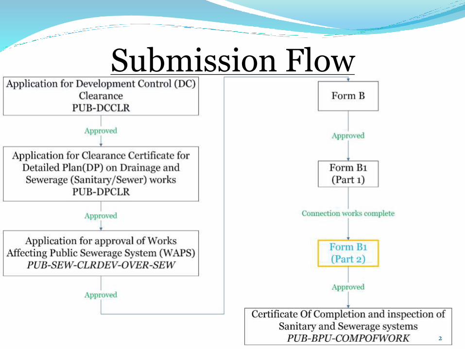
Submission Flow
2
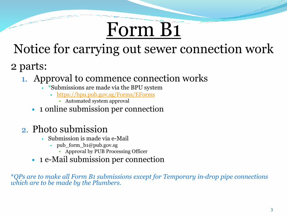
Form B1Notice for carrying out sewer connection work
2 parts:1. Approval to commence connection works
*Submissions are made via the BPU system https://bpu.pub.gov.sg/Forms/EForms
Automated system approval
1 online submission per connection
2. Photo submission Submission is made via e-Mail
[email protected] Approval by PUB Processing Officer
1 e-Mail submission per connection
*QPs are to make all Form B1 submissions except for Temporary in-drop pipe connections which are to be made by the Plumbers.
3
Pages of interest Email Submission Format
Attachments Required
QP Cover Letter Template
LP Cover Letter Template
Channel Levels Channel Levels Photo
Channel Levels Photo Alternatives
Connection Type
How to use the photo form?
Pointers for Photo Form
Common mistakes & observations
4
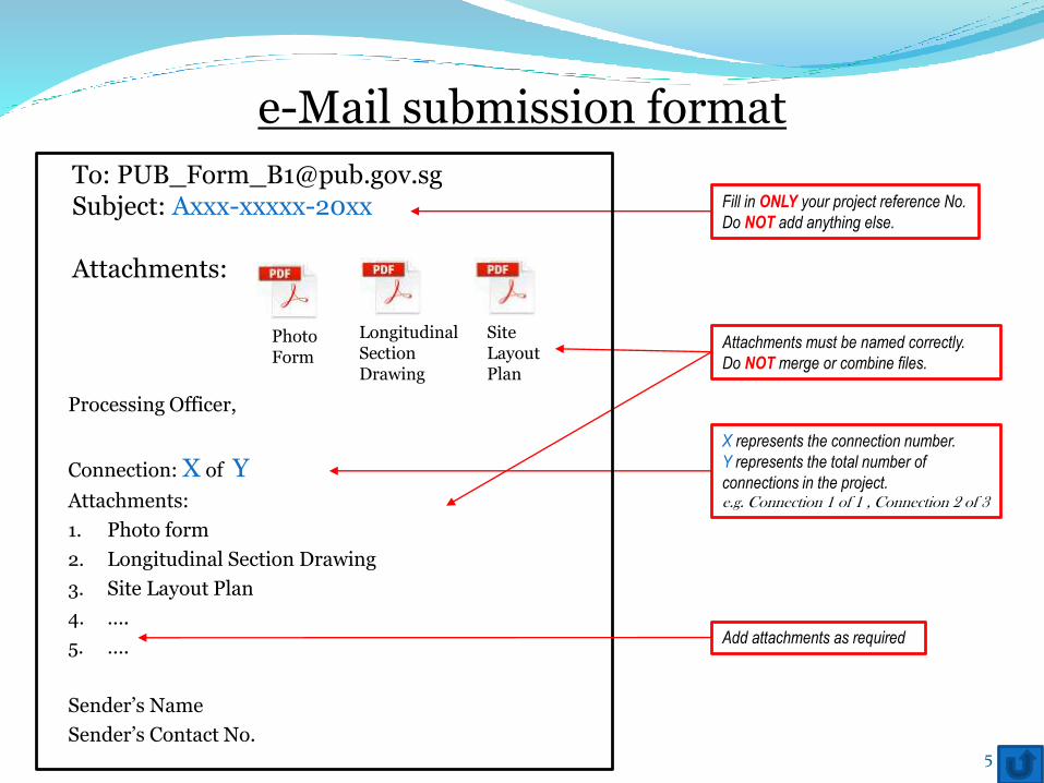
Processing Officer,
Connection: X of YAttachments:
1. Photo form
2. Longitudinal Section Drawing
3. Site Layout Plan
4. ….
5. ….
Sender’s Name
Sender’s Contact No.
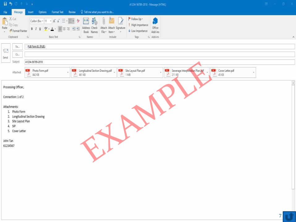
e-Mail submission format
To: [email protected]: Axxx-xxxxx-20xx
Attachments:
Photo Form
Longitudinal Section Drawing
Site Layout Plan
Fill in ONLY your project reference No.
Do NOT add anything else.
Attachments must be named correctly.
Do NOT merge or combine files.
X represents the connection number.
Y represents the total number of
connections in the project.e.g. Connection 1 of 1 , Connection 2 of 3
Add attachments as required
5
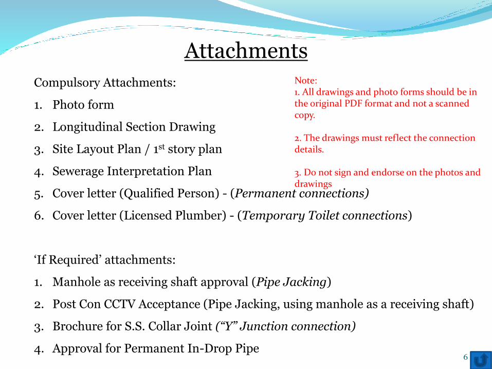
Attachments
Compulsory Attachments:
1. Photo form
2. Longitudinal Section Drawing
3. Site Layout Plan / 1st story plan
4. Sewerage Interpretation Plan
5. Cover letter (Qualified Person) - (Permanent connections)
6. Cover letter (Licensed Plumber) - (Temporary Toilet connections)
‘If Required’ attachments:
1. Manhole as receiving shaft approval (Pipe Jacking)
2. Post Con CCTV Acceptance (Pipe Jacking, using manhole as a receiving shaft)
3. Brochure for S.S. Collar Joint (“Y” Junction connection)
4. Approval for Permanent In-Drop Pipe6
Note:1. All drawings and photo forms should be in the original PDF format and not a scanned copy.
2. The drawings must reflect the connection details.
3. Do not sign and endorse on the photos and drawings
7
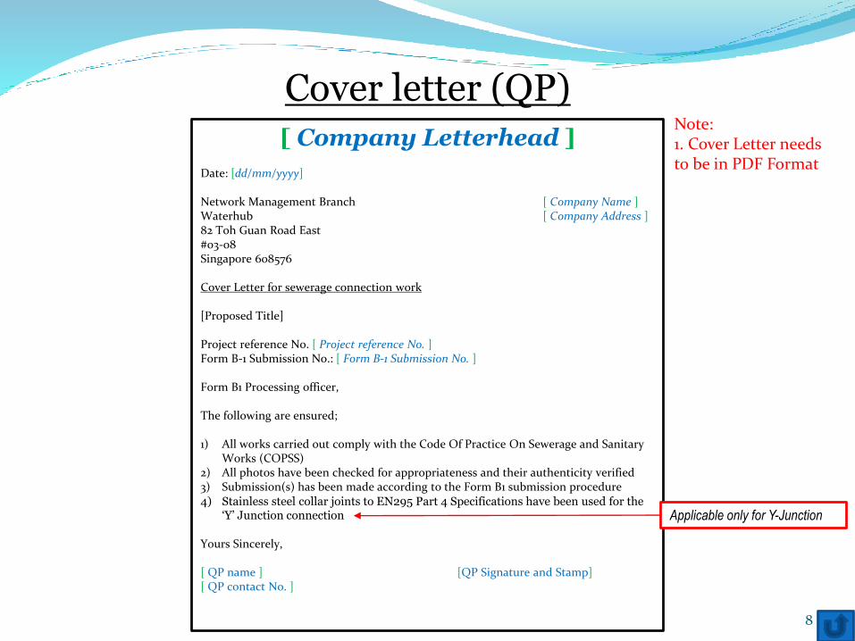
Cover letter (QP)[ Company Letterhead ]
Date: [dd/mm/yyyy]
Network Management Branch [ Company Name ]Waterhub [ Company Address ]82 Toh Guan Road East#03-08Singapore 608576
Cover Letter for sewerage connection work
[Proposed Title]
Project reference No. [ Project reference No. ]Form B-1 Submission No.: [ Form B-1 Submission No. ]
Form B1 Processing officer,
The following are ensured;
1) All works carried out comply with the Code Of Practice On Sewerage and Sanitary Works (COPSS)
2) All photos have been checked for appropriateness and their authenticity verified3) Submission(s) has been made according to the Form B1 submission procedure4) Stainless steel collar joints to EN295 Part 4 Specifications have been used for the
‘Y’ Junction connection
Yours Sincerely,
[ QP name ] [QP Signature and Stamp][ QP contact No. ]
8
Applicable only for Y-Junction
Note:1. Cover Letter needs to be in PDF Format
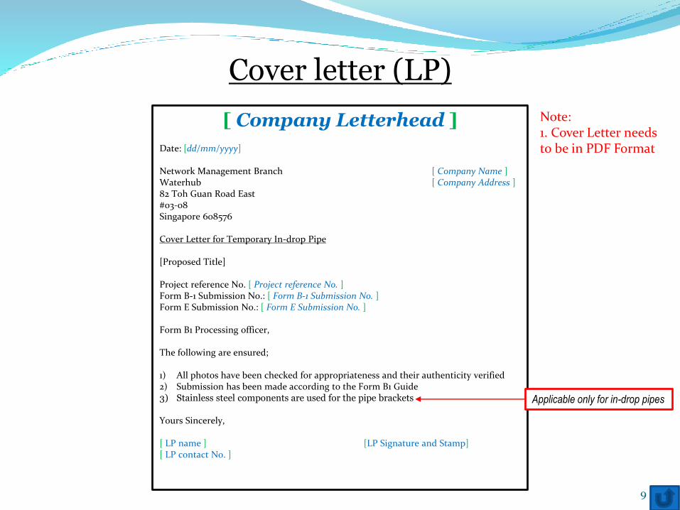
Cover letter (LP)
[ Company Letterhead ]
Date: [dd/mm/yyyy]
Network Management Branch [ Company Name ]Waterhub [ Company Address ]82 Toh Guan Road East#03-08Singapore 608576
Cover Letter for Temporary In-drop Pipe
[Proposed Title]
Project reference No. [ Project reference No. ]Form B-1 Submission No.: [ Form B-1 Submission No. ]Form E Submission No.: [ Form E Submission No. ]
Form B1 Processing officer,
The following are ensured;
1) All photos have been checked for appropriateness and their authenticity verified2) Submission has been made according to the Form B1 Guide3) Stainless steel components are used for the pipe brackets
Yours Sincerely,
[ LP name ] [LP Signature and Stamp][ LP contact No. ]
9
Applicable only for in-drop pipes
Note:1. Cover Letter needs to be in PDF Format
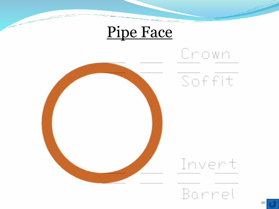
Pipe Face
10
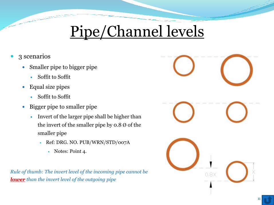
Pipe/Channel levels
3 scenarios
Smaller pipe to bigger pipe
Soffit to Soffit
Equal size pipes
Soffit to Soffit
Bigger pipe to smaller pipe
Invert of the larger pipe shall be higher than
the invert of the smaller pipe by 0.8 Ø of the
smaller pipe
Ref: DRG. NO. PUB/WRN/STD/007A
Notes: Point 4.
Rule of thumb: The invert level of the incoming pipe cannot be
lower than the invert level of the outgoing pipe
11
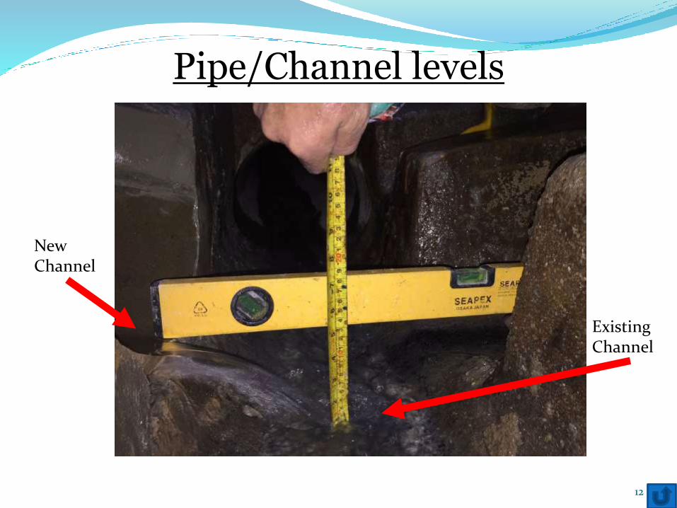
Pipe/Channel levels
12
New Channel
Existing Channel
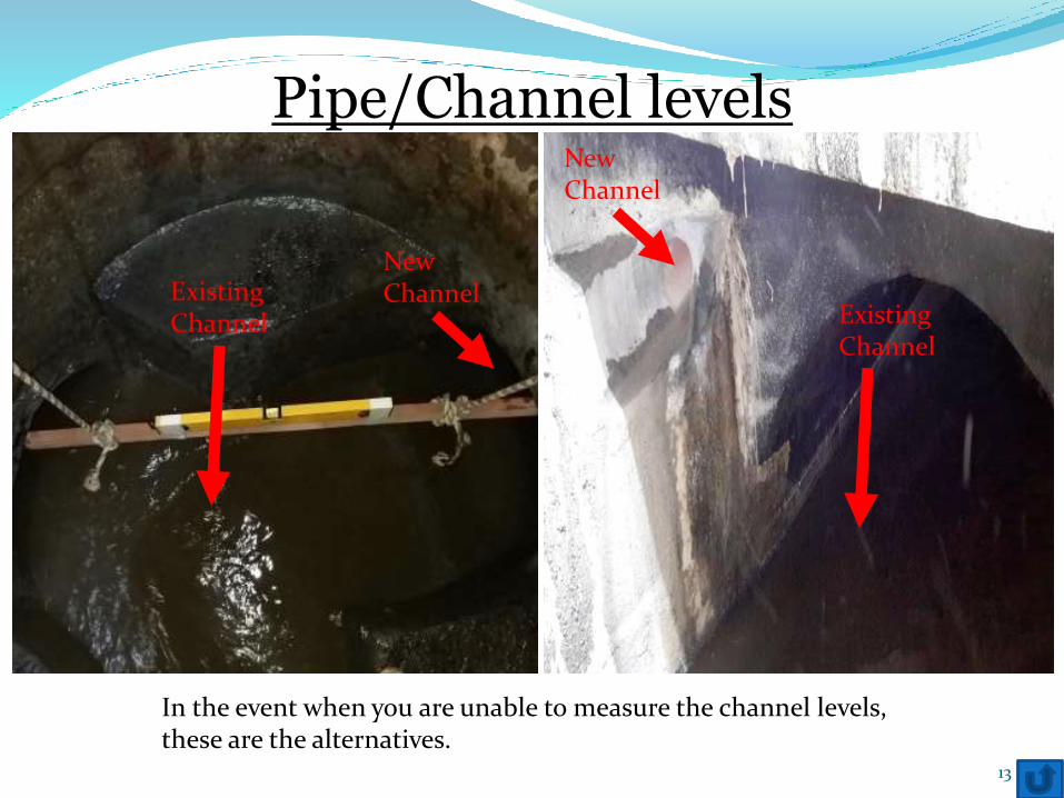
Pipe/Channel levels
13
In the event when you are unable to measure the channel levels, these are the alternatives.
New Channel
Existing Channel
New Channel
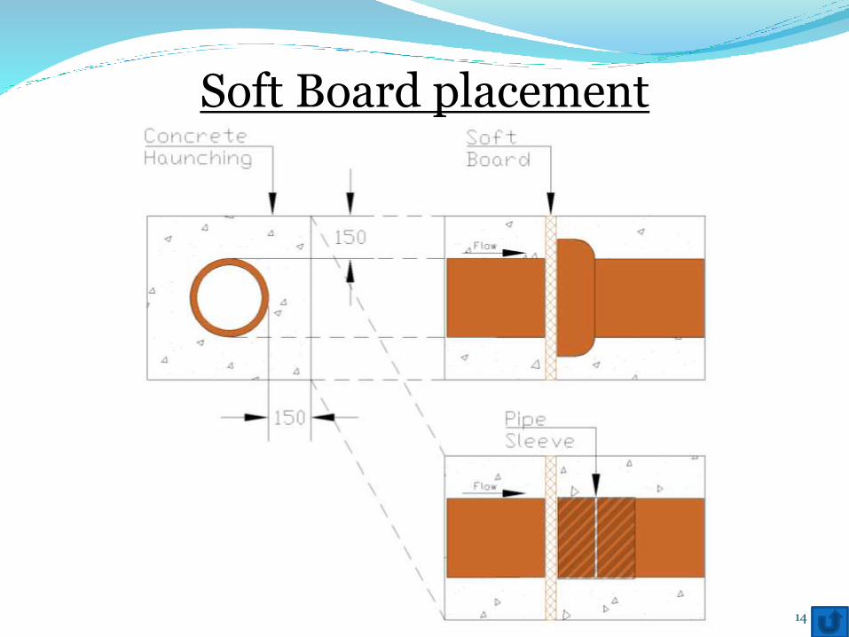
Soft Board placement
14
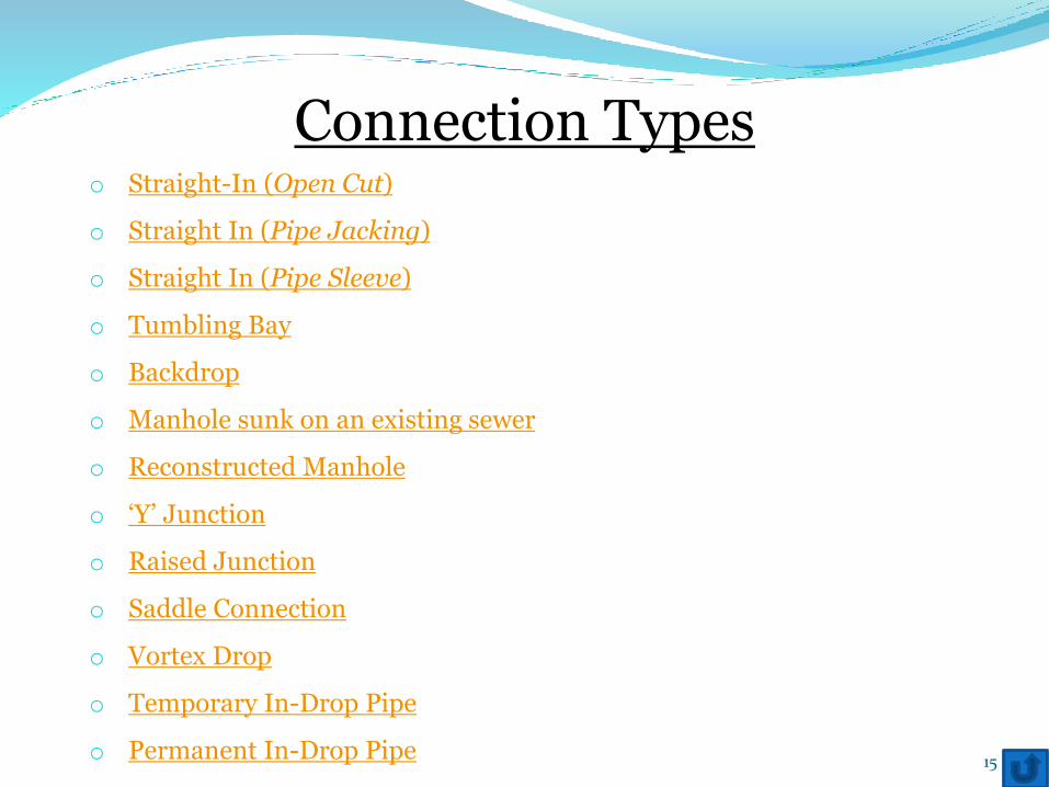
Connection Typeso Straight-In (Open Cut)
o Straight In (Pipe Jacking)
o Straight In (Pipe Sleeve)
o Tumbling Bay
o Backdrop
o Manhole sunk on an existing sewer
o Reconstructed Manhole
o ‘Y’ Junction
o Raised Junction
o Saddle Connection
o Vortex Drop
o Temporary In-Drop Pipe
o Permanent In-Drop Pipe 15
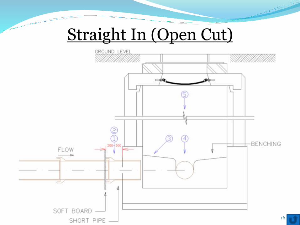
Straight In (Open Cut)
16
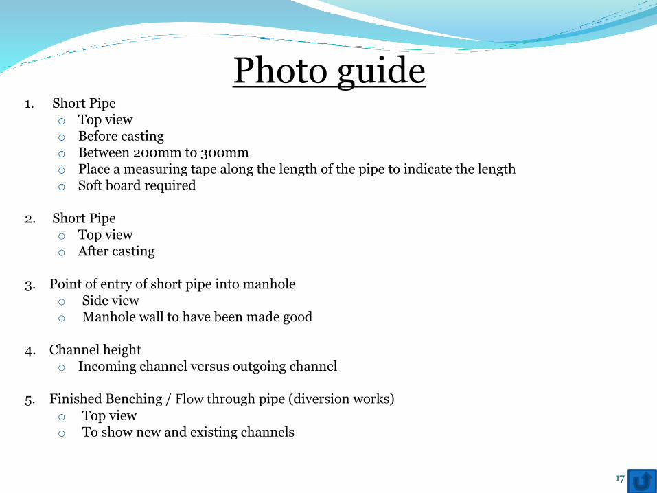
Photo guide1. Short Pipe
o Top viewo Before casting o Between 200mm to 300mmo Place a measuring tape along the length of the pipe to indicate the lengtho Soft board required
2. Short Pipeo Top viewo After casting
3. Point of entry of short pipe into manholeo Side viewo Manhole wall to have been made good
4. Channel heighto Incoming channel versus outgoing channel
5. Finished Benching / Flow through pipe (diversion works)
o Top viewo To show new and existing channels
17
Straight In (Open Cut)Examples of Photos
18PLEASE NOTE THAT THESE ARE EXAMPLES, ACTUAL PHOTOS TAKEN ON SITE MAY DIFFER
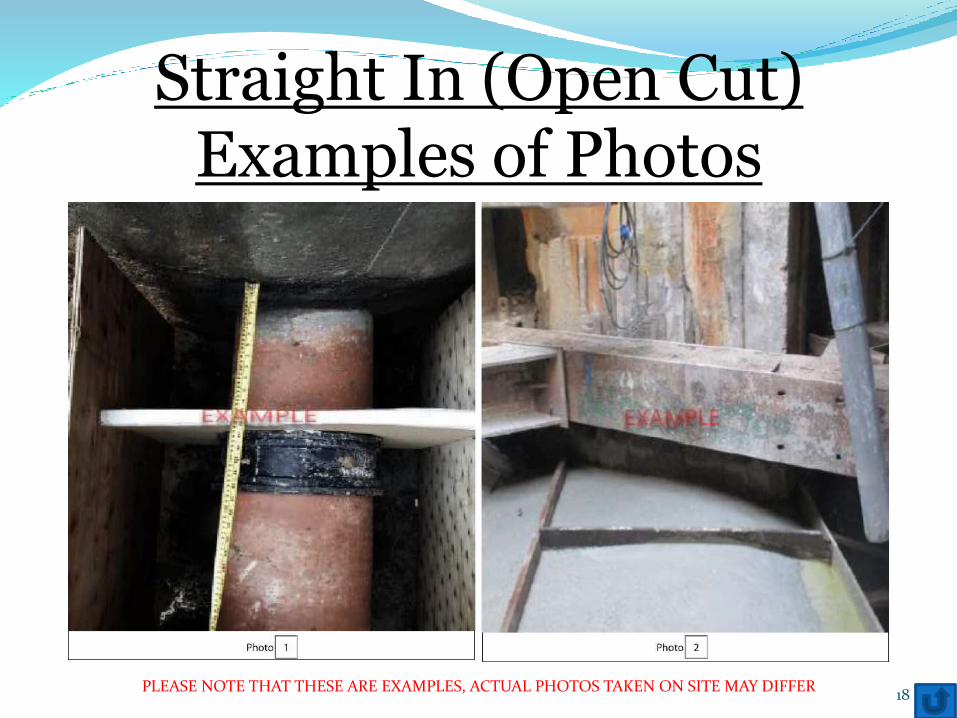
Straight In (Open Cut)Examples of Photos
19PLEASE NOTE THAT THESE ARE EXAMPLES, ACTUAL PHOTOS TAKEN ON SITE MAY DIFFER
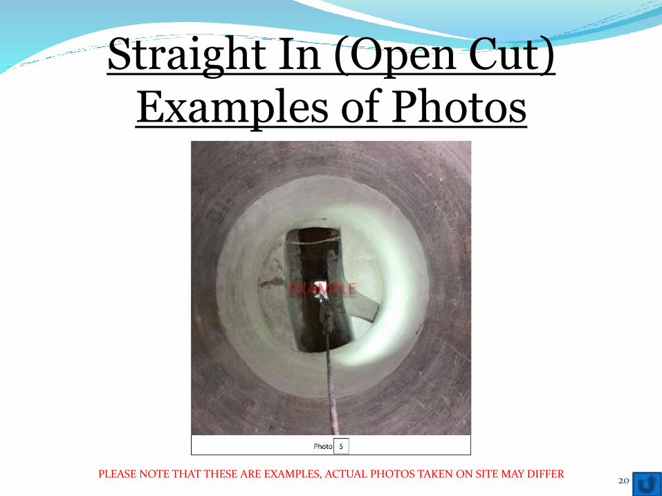
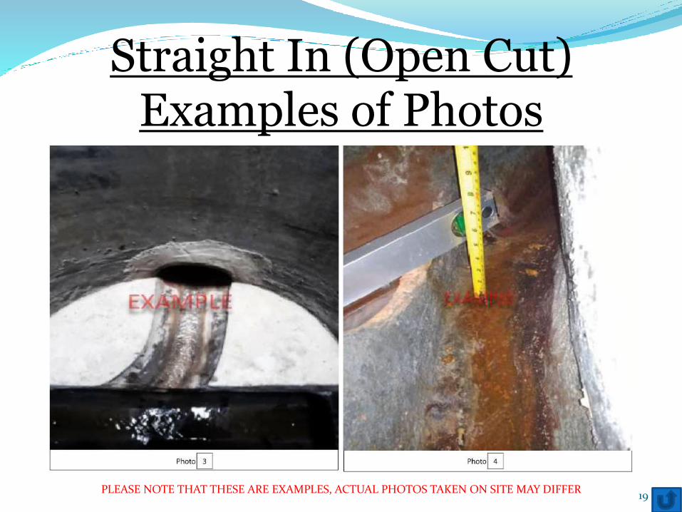
Straight In (Open Cut)Examples of Photos
20PLEASE NOTE THAT THESE ARE EXAMPLES, ACTUAL PHOTOS TAKEN ON SITE MAY DIFFER
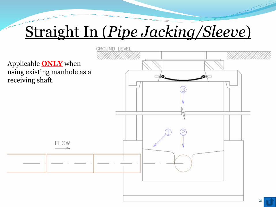
Straight In (Pipe Jacking/Sleeve)
21
Applicable ONLY when using existing manhole as a receiving shaft.
Photo guide1. Point of entry of short pipe into manhole
o Side viewo Manhole wall to have been made good
2. Channel heighto Incoming channel versus outgoing channel
3. Finished Benching / Flow through pipe (diversion works)
o Top viewo To show new and existing channels
22
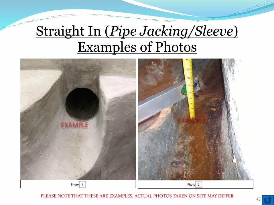
Straight In (Pipe Jacking/Sleeve)Examples of Photos
23PLEASE NOTE THAT THESE ARE EXAMPLES, ACTUAL PHOTOS TAKEN ON SITE MAY DIFFER
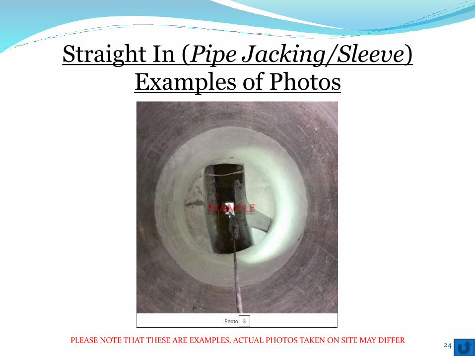
Straight In (Pipe Jacking/Sleeve)Examples of Photos
24PLEASE NOTE THAT THESE ARE EXAMPLES, ACTUAL PHOTOS TAKEN ON SITE MAY DIFFER
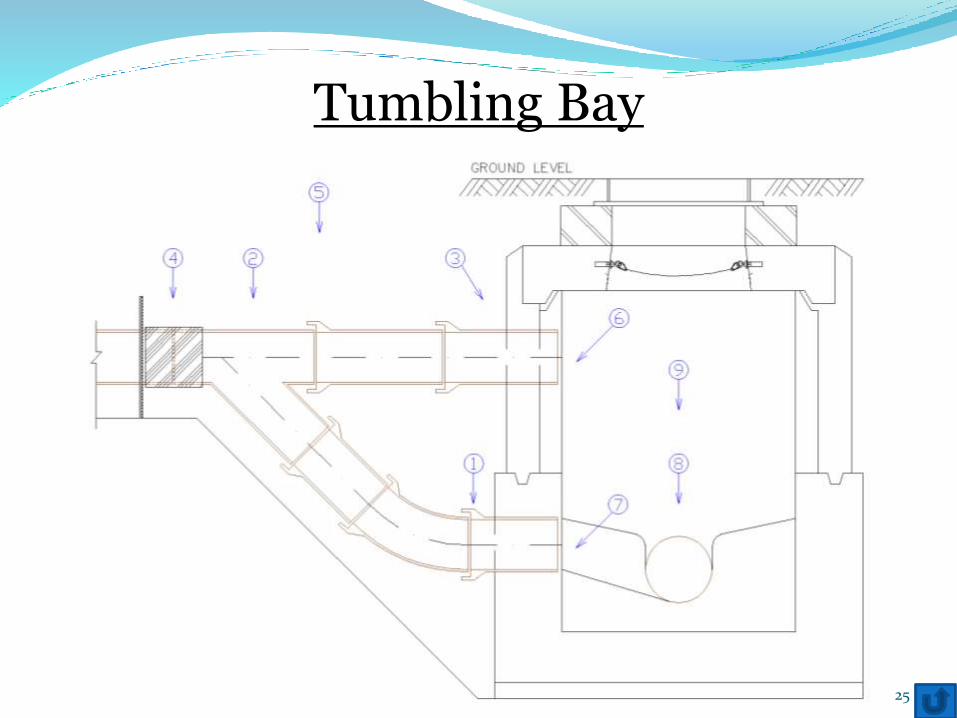
Tumbling Bay
25
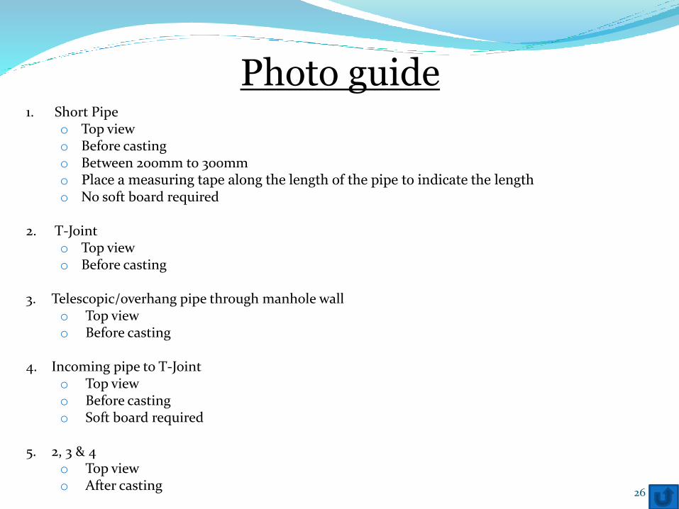
Photo guide1. Short Pipe
o Top viewo Before casting o Between 200mm to 300mmo Place a measuring tape along the length of the pipe to indicate the lengtho No soft board required
2. T-Jointo Top viewo Before casting
3. Telescopic/overhang pipe through manhole wallo Top viewo Before casting
4. Incoming pipe to T-Jointo Top viewo Before castingo Soft board required
5. 2, 3 & 4o Top viewo After casting
26
6. Point of entry of telescopic/overhang pipe into manholeo Side viewo Manhole wall to have been made good
7. Point of entry of short pipe into manholeo Side viewo Manhole wall to have been made good
8. Channel heighto Incoming channel versus outgoing channel
9. Finished Benching / Flow through pipe (diversion works)o Top view
Photo guide
27
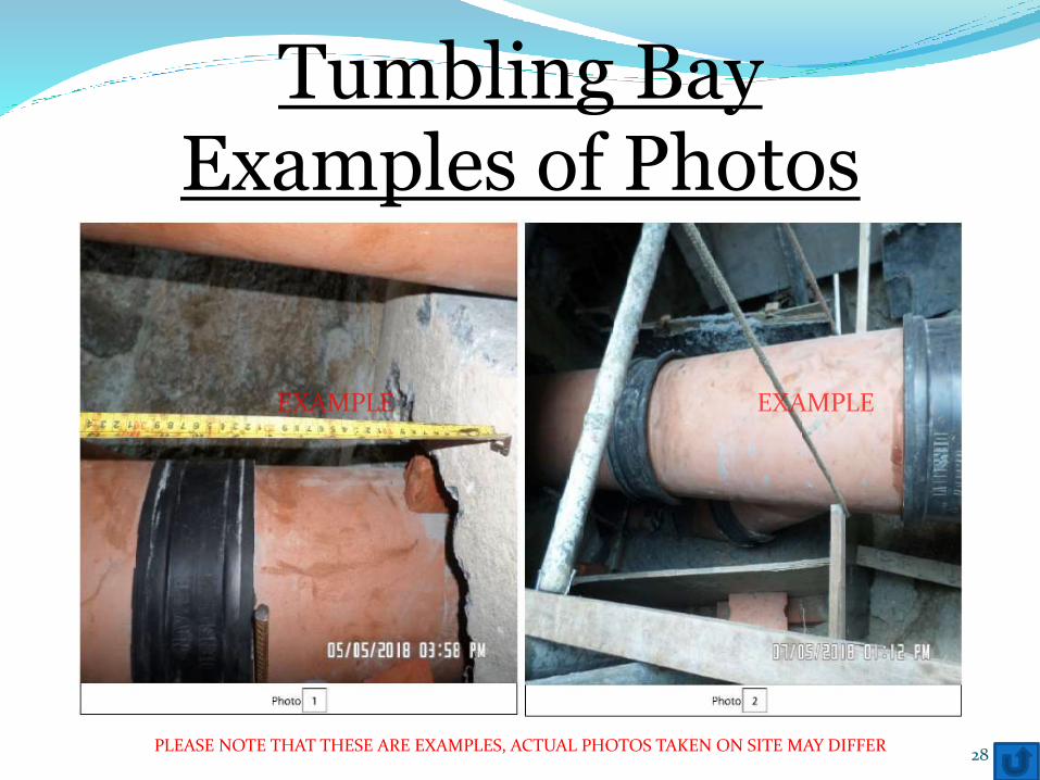
Tumbling BayExamples of Photos
28PLEASE NOTE THAT THESE ARE EXAMPLES, ACTUAL PHOTOS TAKEN ON SITE MAY DIFFER
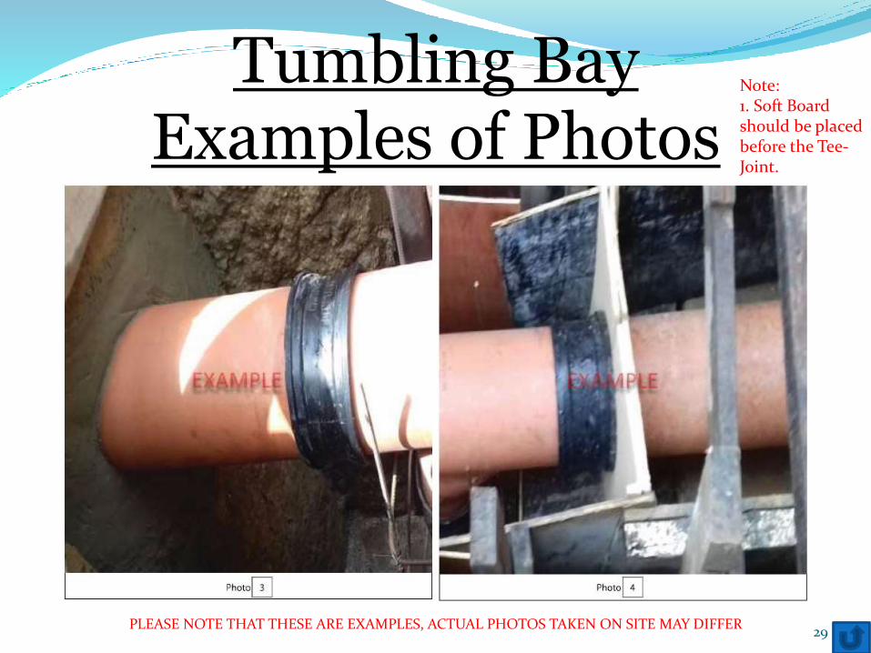
Tumbling BayExamples of Photos
29PLEASE NOTE THAT THESE ARE EXAMPLES, ACTUAL PHOTOS TAKEN ON SITE MAY DIFFER
Note:1. Soft Board should be placed before the Tee-Joint.
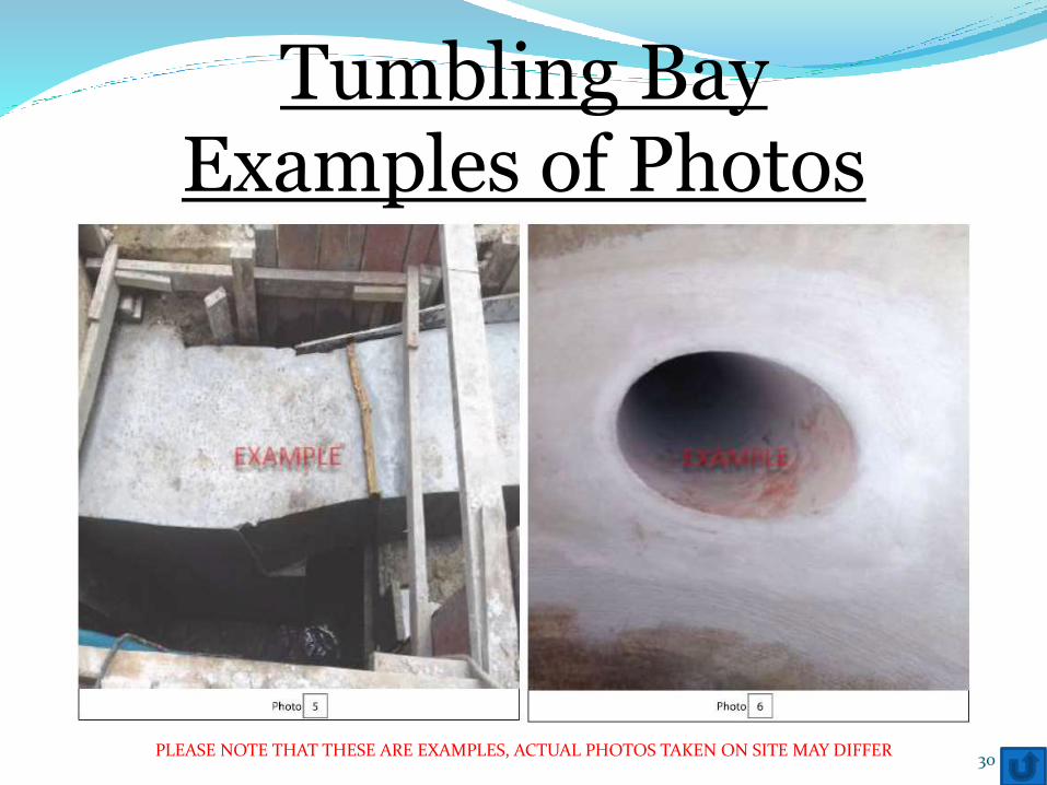
30PLEASE NOTE THAT THESE ARE EXAMPLES, ACTUAL PHOTOS TAKEN ON SITE MAY DIFFER
Tumbling BayExamples of Photos
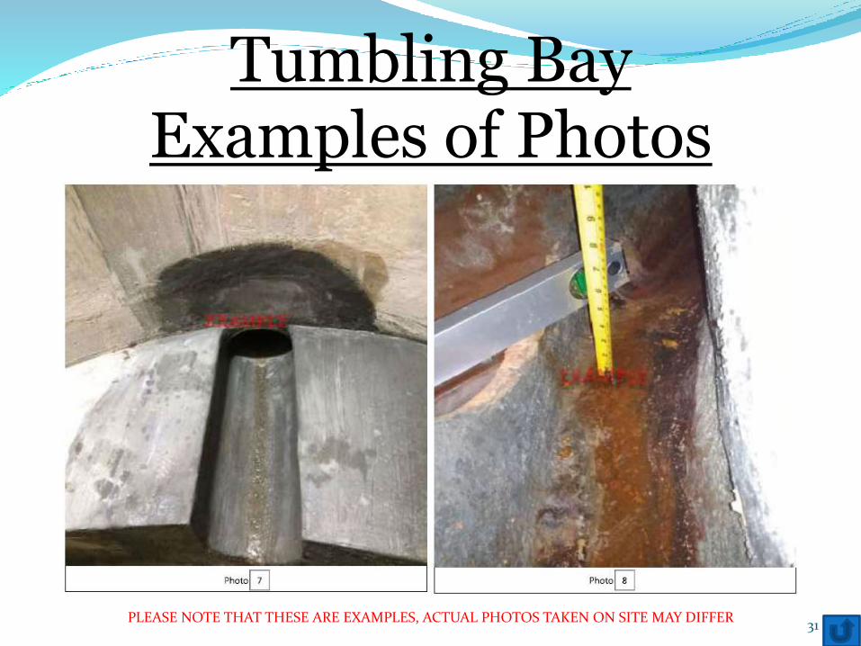
Tumbling BayExamples of Photos
31PLEASE NOTE THAT THESE ARE EXAMPLES, ACTUAL PHOTOS TAKEN ON SITE MAY DIFFER
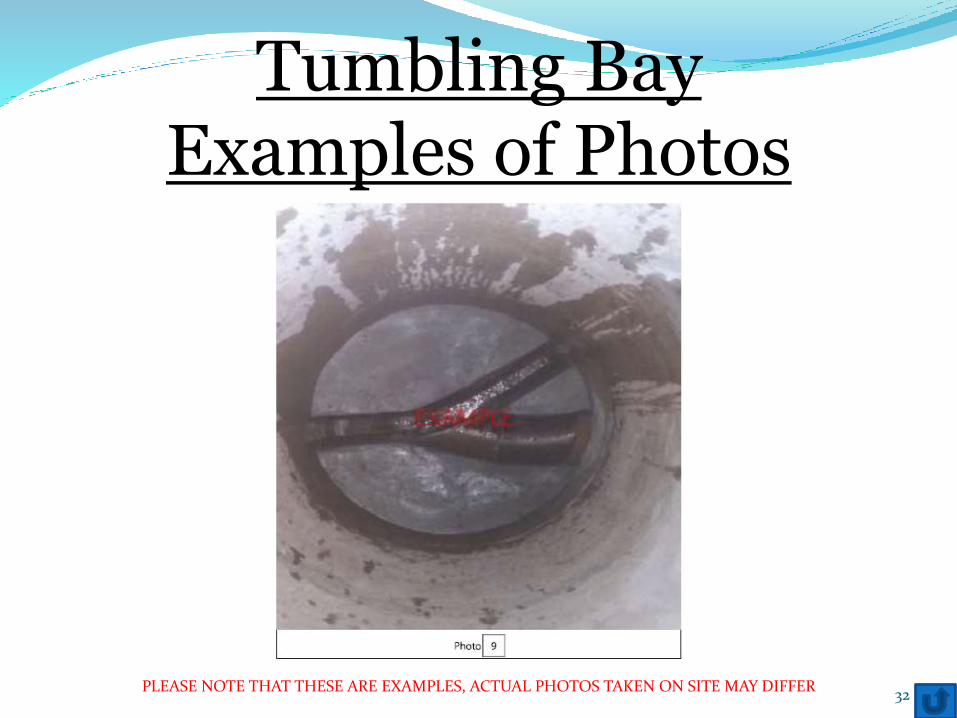
Tumbling BayExamples of Photos
32PLEASE NOTE THAT THESE ARE EXAMPLES, ACTUAL PHOTOS TAKEN ON SITE MAY DIFFER
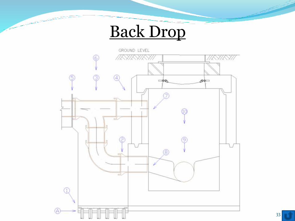
Back Drop
33
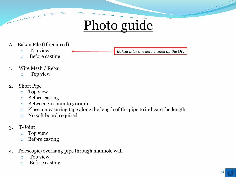
Photo guide
A. Bakau Pile (If required)o Top viewo Before casting
1. Wire Mesh / Rebaro Top view
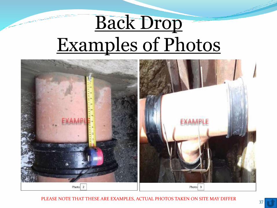
2. Short Pipeo Top viewo Before casting o Between 200mm to 300mmo Place a measuring tape along the length of the pipe to indicate the lengtho No soft board required
3. T-Jointo Top viewo Before casting
4. Telescopic/overhang pipe through manhole wallo Top viewo Before casting
34
Bakau piles are determined by the QP.
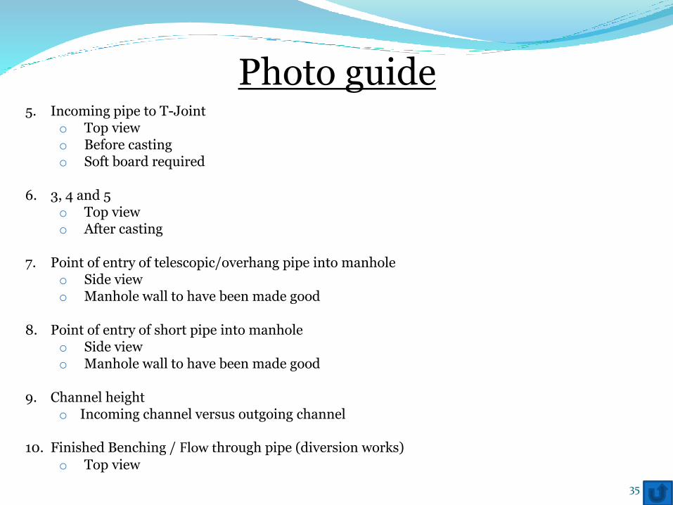
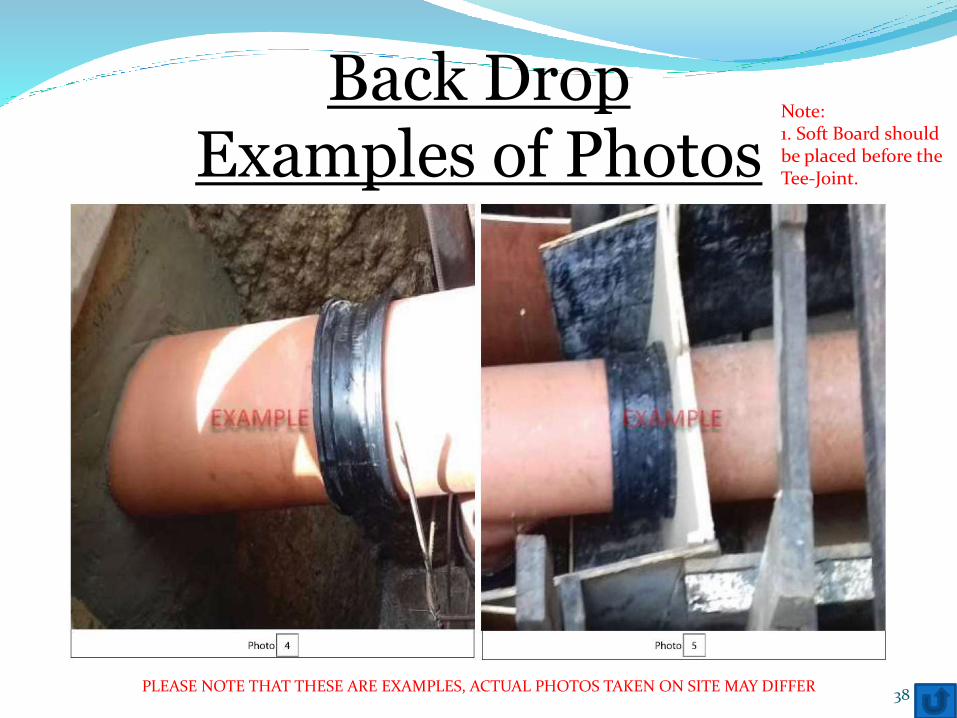
5. Incoming pipe to T-Jointo Top viewo Before castingo Soft board required
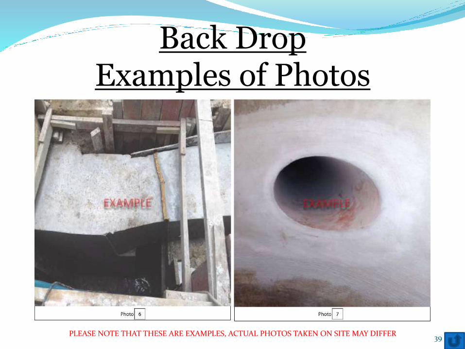
6. 3, 4 and 5o Top viewo After casting
7. Point of entry of telescopic/overhang pipe into manholeo Side viewo Manhole wall to have been made good
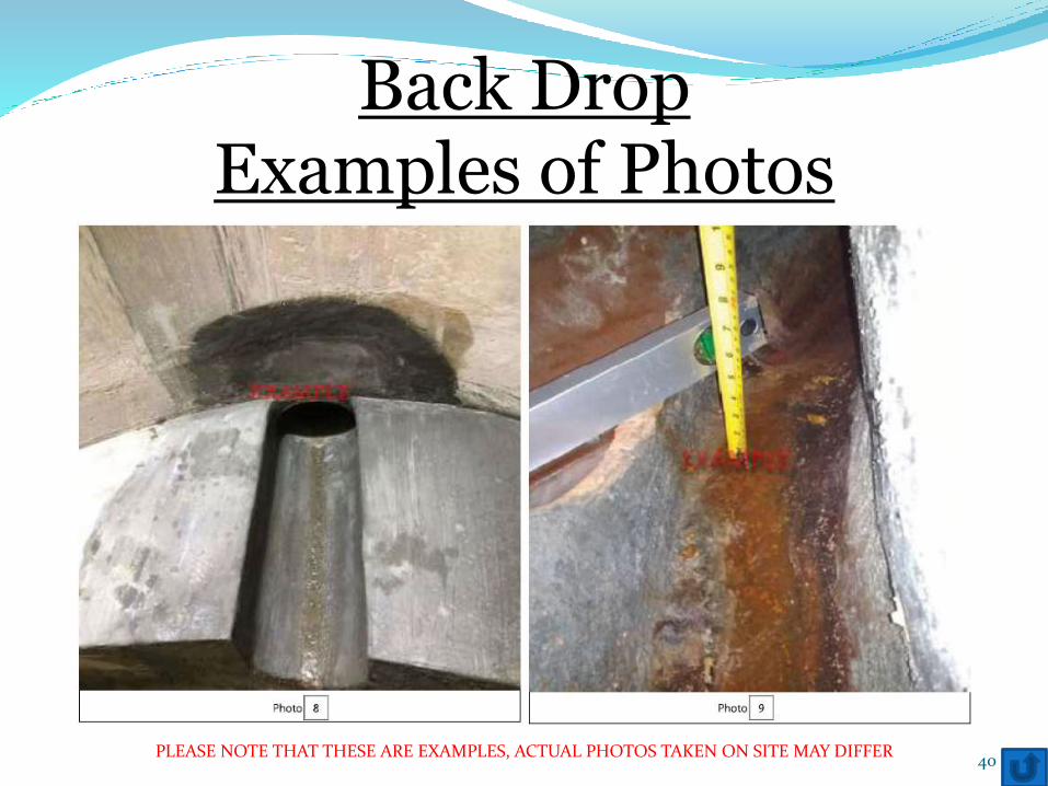
8. Point of entry of short pipe into manholeo Side viewo Manhole wall to have been made good
9. Channel heighto Incoming channel versus outgoing channel
10. Finished Benching / Flow through pipe (diversion works)
o Top view
Photo guide
35
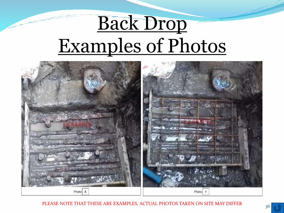
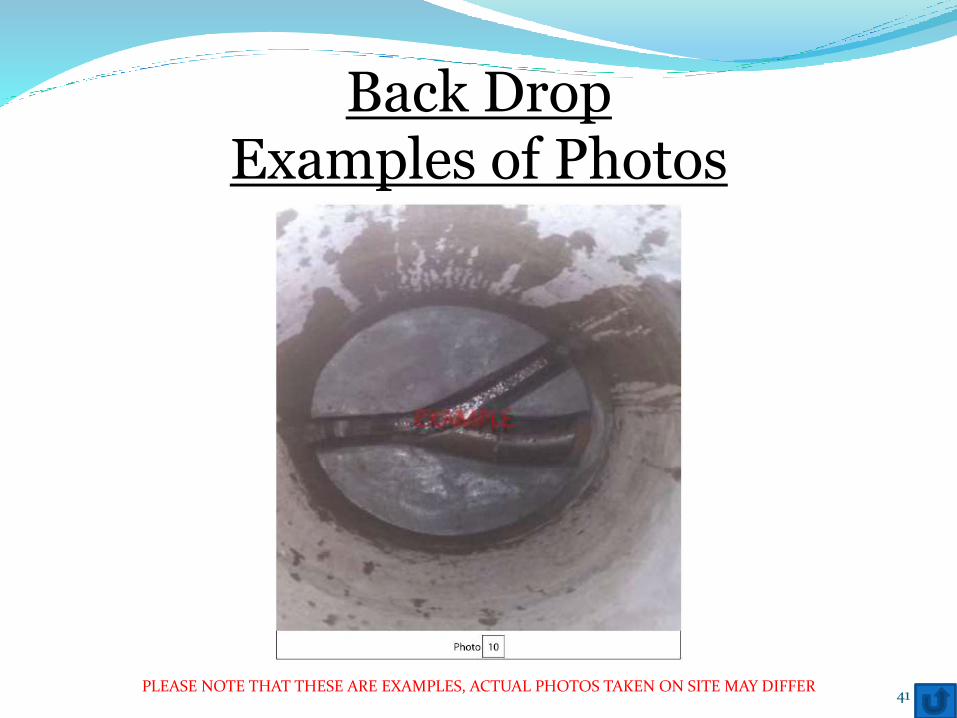
Back DropExamples of Photos
36PLEASE NOTE THAT THESE ARE EXAMPLES, ACTUAL PHOTOS TAKEN ON SITE MAY DIFFER
Back DropExamples of Photos
37PLEASE NOTE THAT THESE ARE EXAMPLES, ACTUAL PHOTOS TAKEN ON SITE MAY DIFFER
Back DropExamples of Photos
38PLEASE NOTE THAT THESE ARE EXAMPLES, ACTUAL PHOTOS TAKEN ON SITE MAY DIFFER
Note:1. Soft Board should be placed before the Tee-Joint.
Back DropExamples of Photos
39PLEASE NOTE THAT THESE ARE EXAMPLES, ACTUAL PHOTOS TAKEN ON SITE MAY DIFFER
Back DropExamples of Photos
40PLEASE NOTE THAT THESE ARE EXAMPLES, ACTUAL PHOTOS TAKEN ON SITE MAY DIFFER
Back DropExamples of Photos
41PLEASE NOTE THAT THESE ARE EXAMPLES, ACTUAL PHOTOS TAKEN ON SITE MAY DIFFER
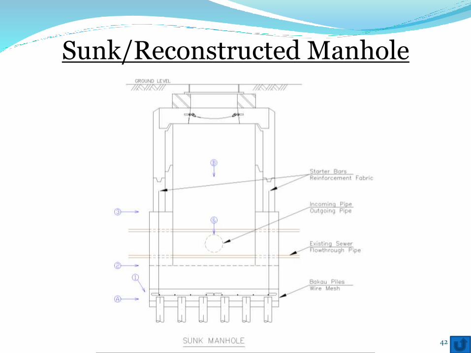
Sunk/Reconstructed Manhole
42
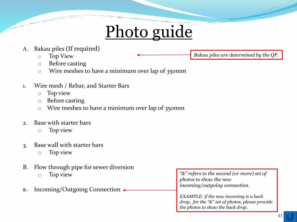
A. Bakau piles (If required)o Top Viewo Before castingo Wire meshes to have a minimum over lap of 350mm
1. Wire mesh / Rebar, and Starter Barso Top viewo Before castingo Wire meshes to have a minimum over lap of 350mm
2. Base with starter barso Top view
3. Base wall with starter barso Top view
B. Flow through pipe for sewer diversiono Top view
& Incoming/Outgoing Connection
Photo guide
43
“&” refers to the second (or more) set of photos to show the new incoming/outgoing connection.
EXAMPLE: if the new incoming is a back drop, for the “&” set of photos, please provide the photos to show the back drop.
Bakau piles are determined by the QP.
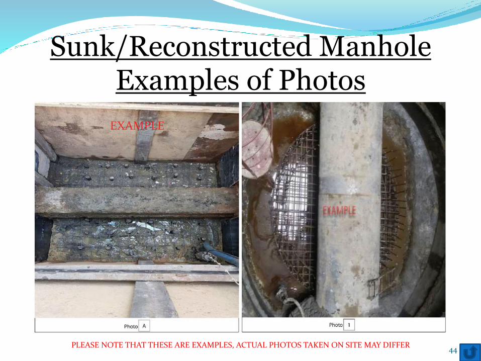
Sunk/Reconstructed ManholeExamples of Photos
44PLEASE NOTE THAT THESE ARE EXAMPLES, ACTUAL PHOTOS TAKEN ON SITE MAY DIFFER
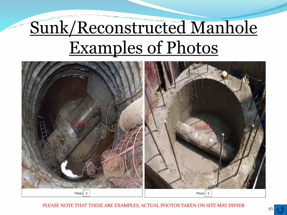
Sunk/Reconstructed ManholeExamples of Photos
45PLEASE NOTE THAT THESE ARE EXAMPLES, ACTUAL PHOTOS TAKEN ON SITE MAY DIFFER
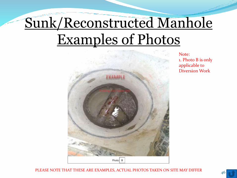
Sunk/Reconstructed ManholeExamples of Photos
46
Note:1. Photo B is only applicable to Diversion Work
PLEASE NOTE THAT THESE ARE EXAMPLES, ACTUAL PHOTOS TAKEN ON SITE MAY DIFFER
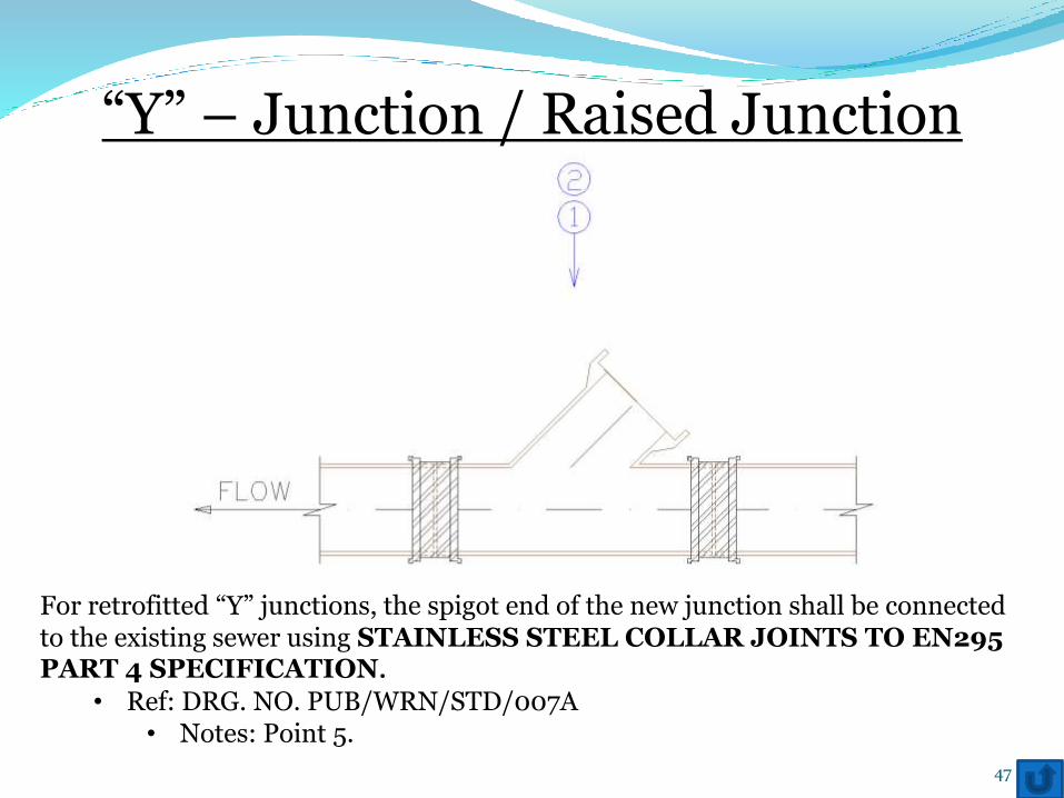
“Y” – Junction / Raised Junction
For retrofitted “Y” junctions, the spigot end of the new junction shall be connected to the existing sewer using STAINLESS STEEL COLLAR JOINTS TO EN295 PART 4 SPECIFICATION.
• Ref: DRG. NO. PUB/WRN/STD/007A• Notes: Point 5.
47
1. Stainless Steel Collar Jointso Top viewo All stainless steel collar joints to be captured in the photo
2. “Y” – Junction / Raised Junctiono Top viewo After casting
Photo guide
48
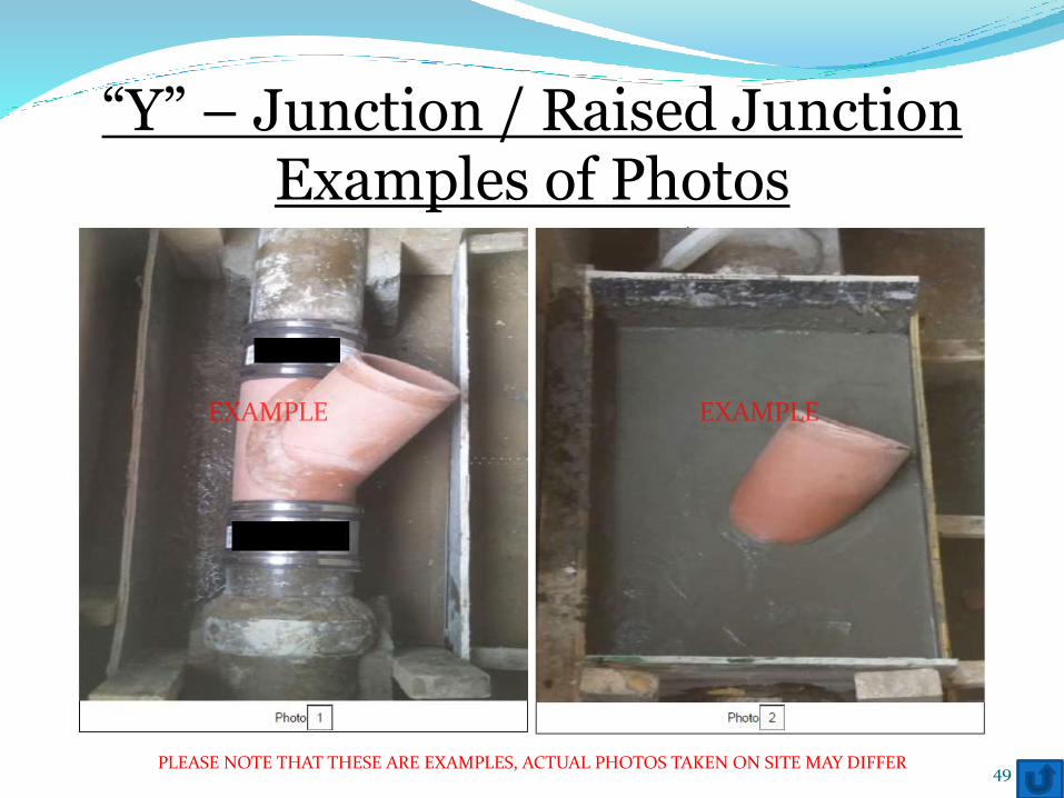
“Y” – Junction / Raised JunctionExamples of Photos
49PLEASE NOTE THAT THESE ARE EXAMPLES, ACTUAL PHOTOS TAKEN ON SITE MAY DIFFER
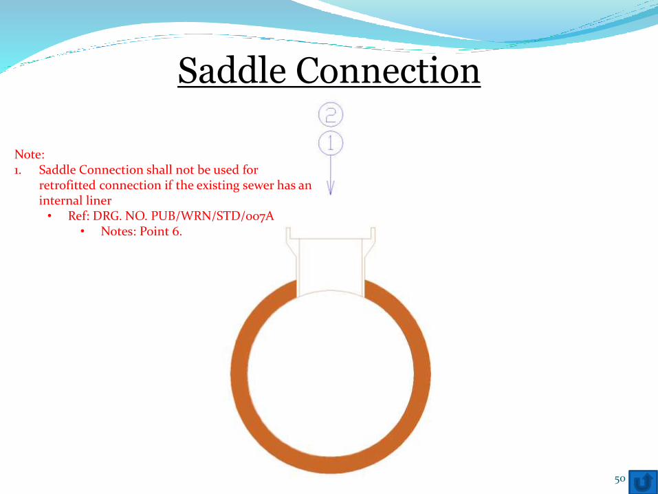
Saddle Connection
50
Note:1. Saddle Connection shall not be used for
retrofitted connection if the existing sewer has an internal liner• Ref: DRG. NO. PUB/WRN/STD/007A
• Notes: Point 6.
1. Incoming pipeo Top viewo Before Casting
2. Incoming pipeo Top viewo After casting
Photo guide
51
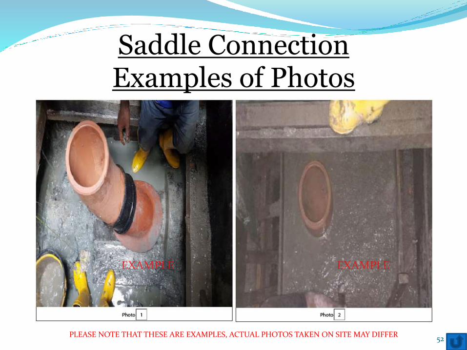
Saddle ConnectionExamples of Photos
52PLEASE NOTE THAT THESE ARE EXAMPLES, ACTUAL PHOTOS TAKEN ON SITE MAY DIFFER
Vortex Drop
Requirements for Vortex drops are on a case-by-case basis. Beforecommencement of work, please make an appointment with the Form B1Processing Officer for consultation.
You are required to bring along the longitudinal section drawing and method ofstatement for the consultation.
53
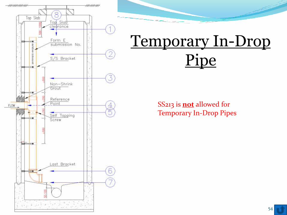
Temporary In-Drop Pipe
54
SS213 is not allowed for Temporary In-Drop Pipes
Top Slab clearance
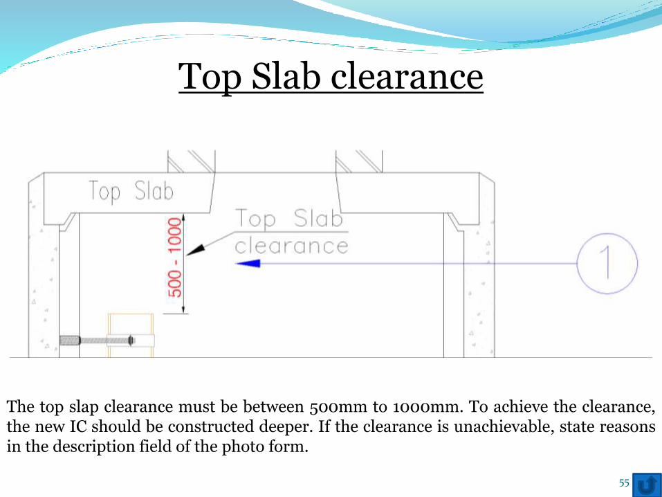
The top slap clearance must be between 500mm to 1000mm. To achieve the clearance,the new IC should be constructed deeper. If the clearance is unachievable, state reasonsin the description field of the photo form.
55
Form E Submission No.
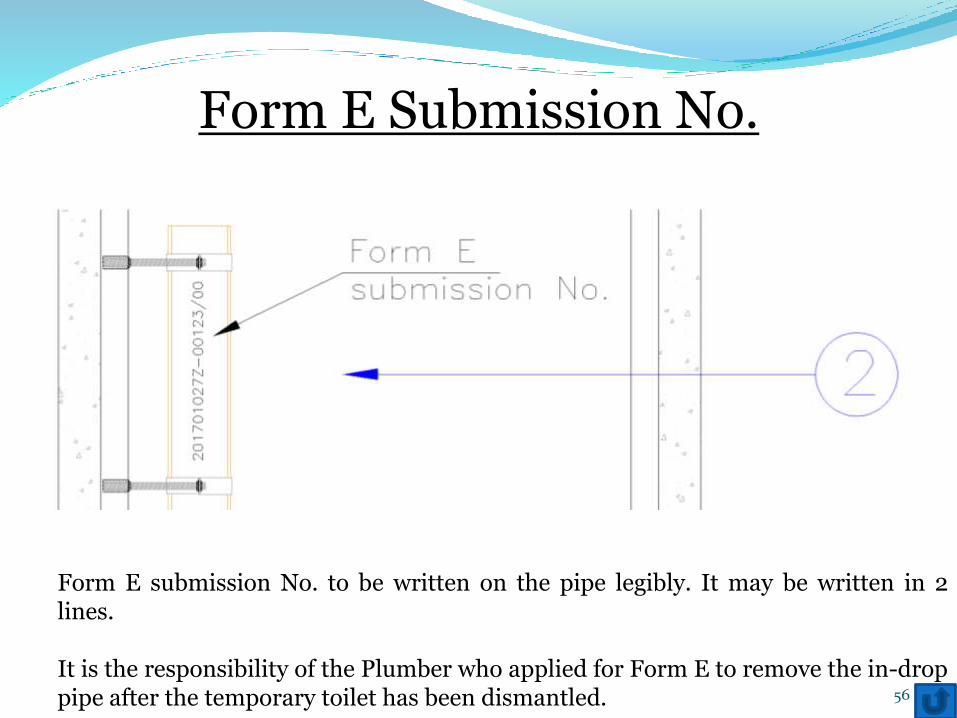
Form E submission No. to be written on the pipe legibly. It may be written in 2lines.
It is the responsibility of the Plumber who applied for Form E to remove the in-droppipe after the temporary toilet has been dismantled. 56
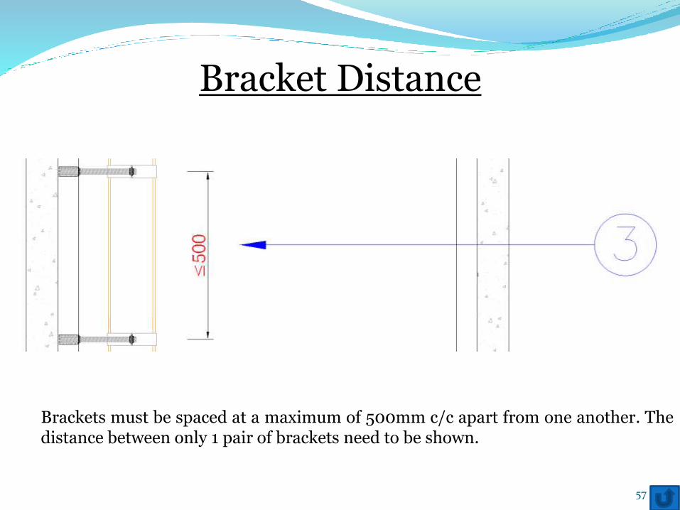
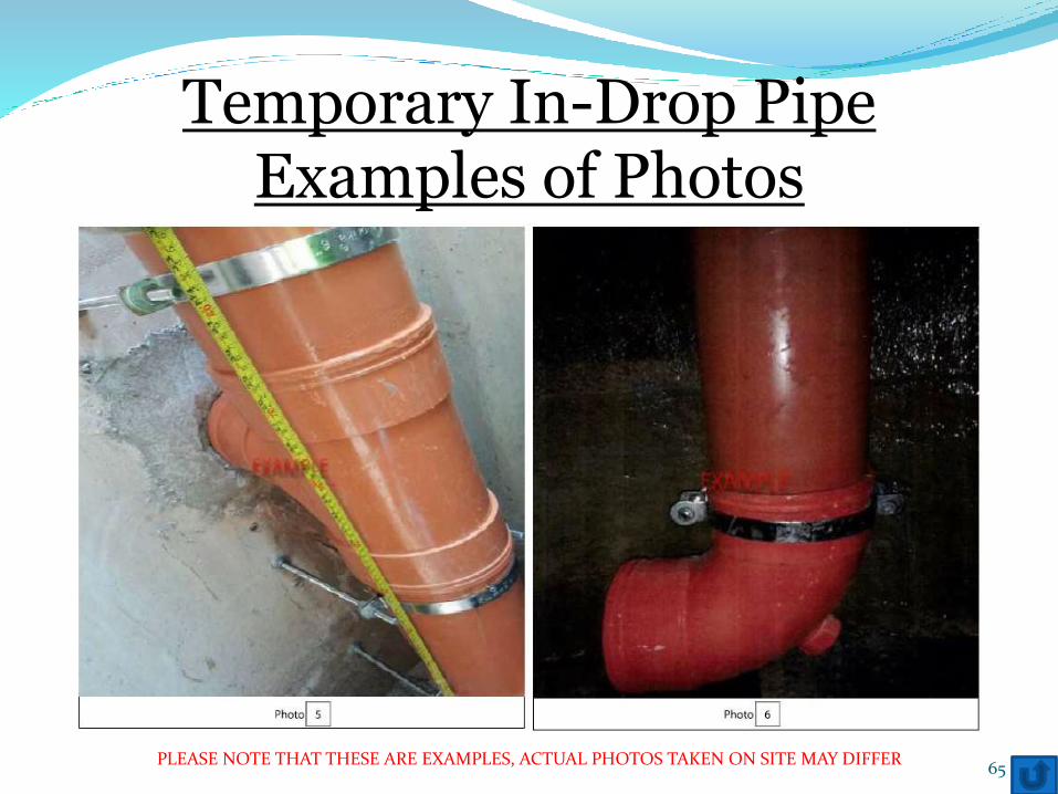
Bracket Distance
Brackets must be spaced at a maximum of 500mm c/c apart from one another. Thedistance between only 1 pair of brackets need to be shown.
57
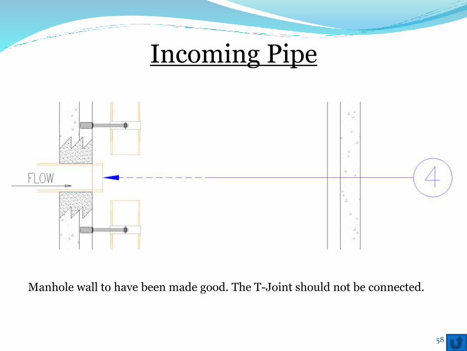
Incoming Pipe
Manhole wall to have been made good. The T-Joint should not be connected.
58
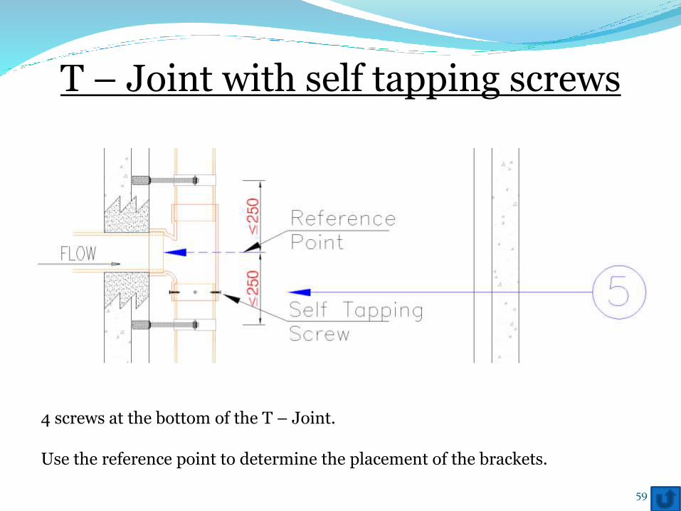
T – Joint with self tapping screws
4 screws at the bottom of the T – Joint.
Use the reference point to determine the placement of the brackets.
59
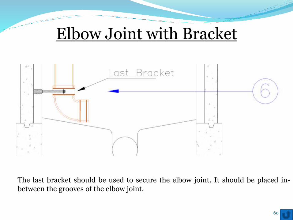
Elbow Joint with Bracket
The last bracket should be used to secure the elbow joint. It should be placed in-between the grooves of the elbow joint.
60
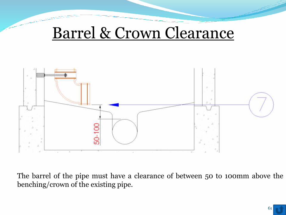
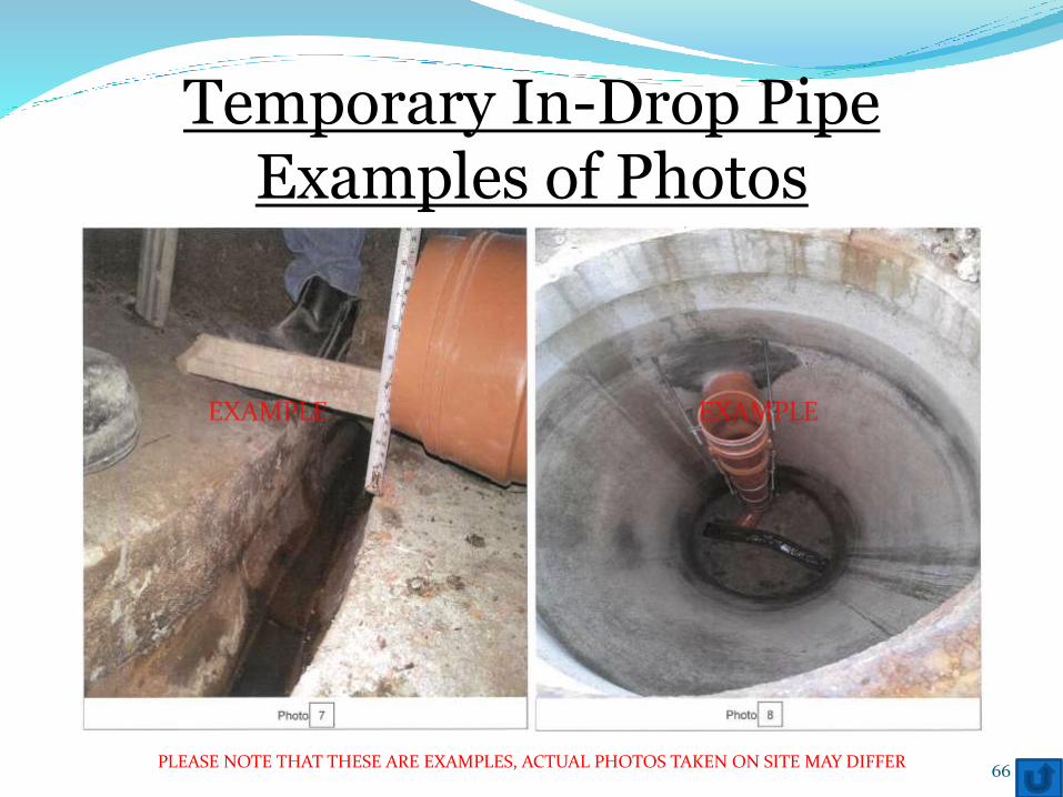
Barrel & Crown Clearance
The barrel of the pipe must have a clearance of between 50 to 100mm above thebenching/crown of the existing pipe.
61
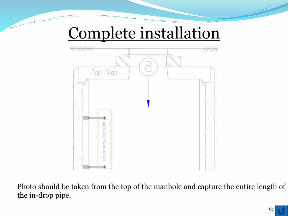
Complete installation
Photo should be taken from the top of the manhole and capture the entire length ofthe in-drop pipe.
62
Temporary In-Drop PipeExamples of Photos
63PLEASE NOTE THAT THESE ARE EXAMPLES, ACTUAL PHOTOS TAKEN ON SITE MAY DIFFER
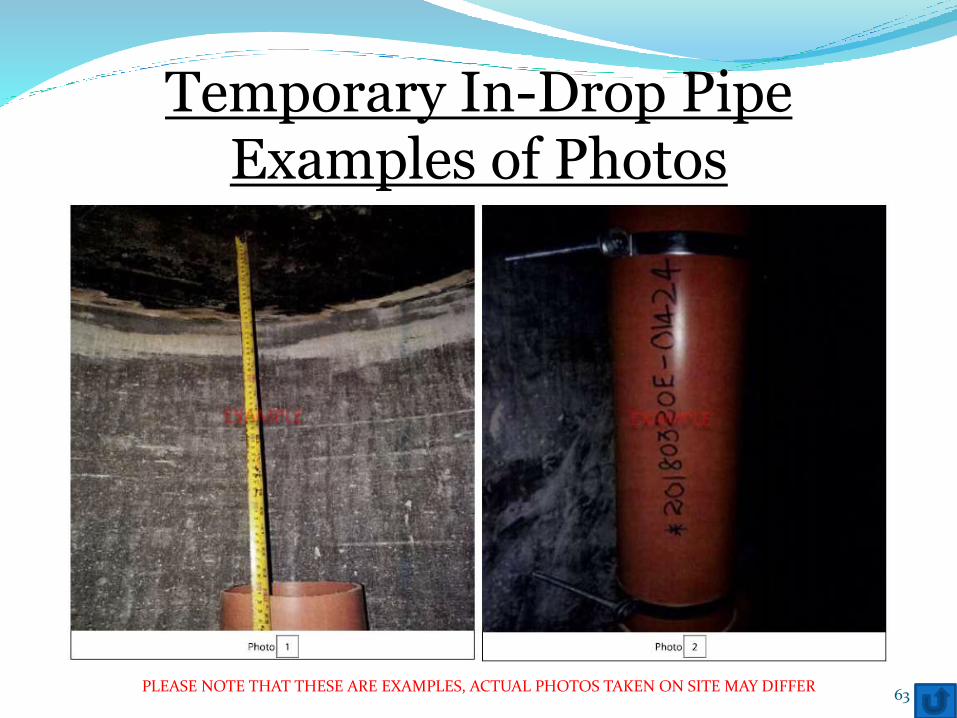
Temporary In-Drop PipeExamples of Photos
64PLEASE NOTE THAT THESE ARE EXAMPLES, ACTUAL PHOTOS TAKEN ON SITE MAY DIFFER
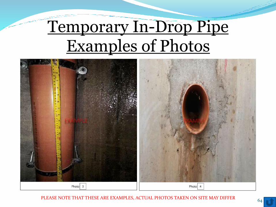
Temporary In-Drop PipeExamples of Photos
65PLEASE NOTE THAT THESE ARE EXAMPLES, ACTUAL PHOTOS TAKEN ON SITE MAY DIFFER
Temporary In-Drop PipeExamples of Photos
66PLEASE NOTE THAT THESE ARE EXAMPLES, ACTUAL PHOTOS TAKEN ON SITE MAY DIFFER
Permanent In-Drop Pipe
Permanent In-Drop Pipes have the same requirements as Temporary In-Drop Pipesexcept for a few differences i.e.
1. The pipe material has to be SS316. PVC/uPVC is not allowed
2. Brackets have to be of Stainless Steel grade 316.
3. Bracket distance is reduced from 500mm to 300mm
67
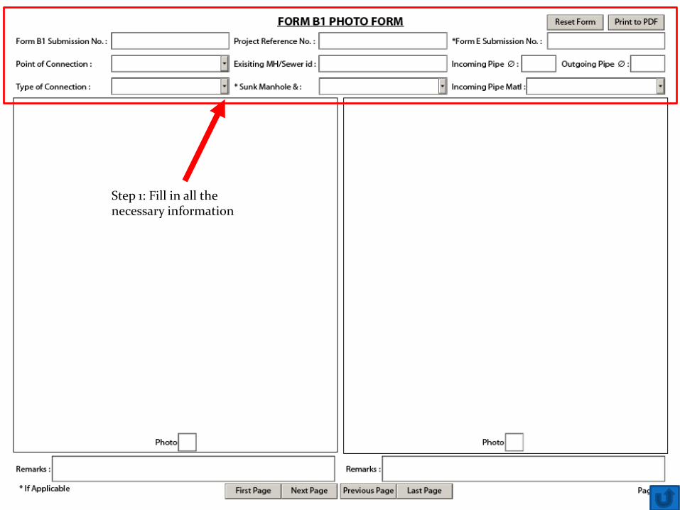
How to use the photo form?
69
Step 1: Fill in all the necessary information
70
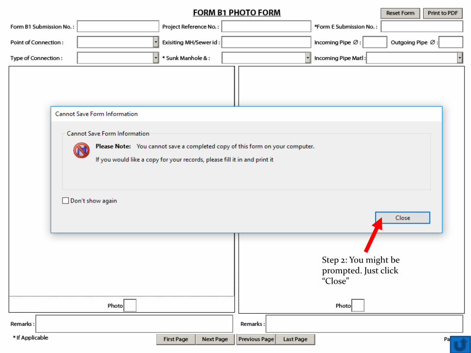
Step 2: You might be prompted. Just click “Close”
71
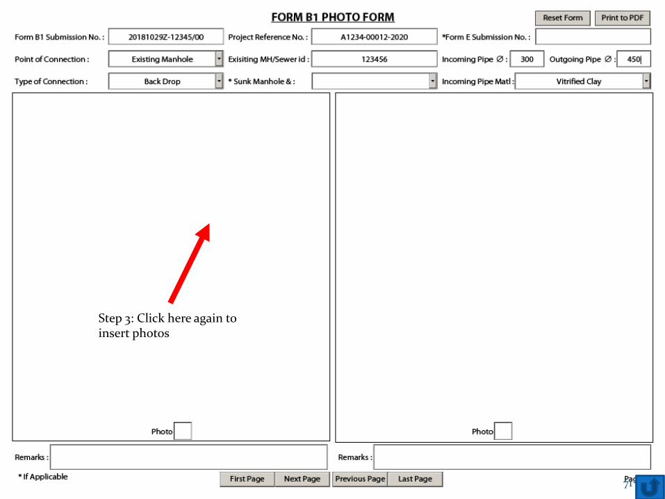
Step 3: Click here again to insert photos
72
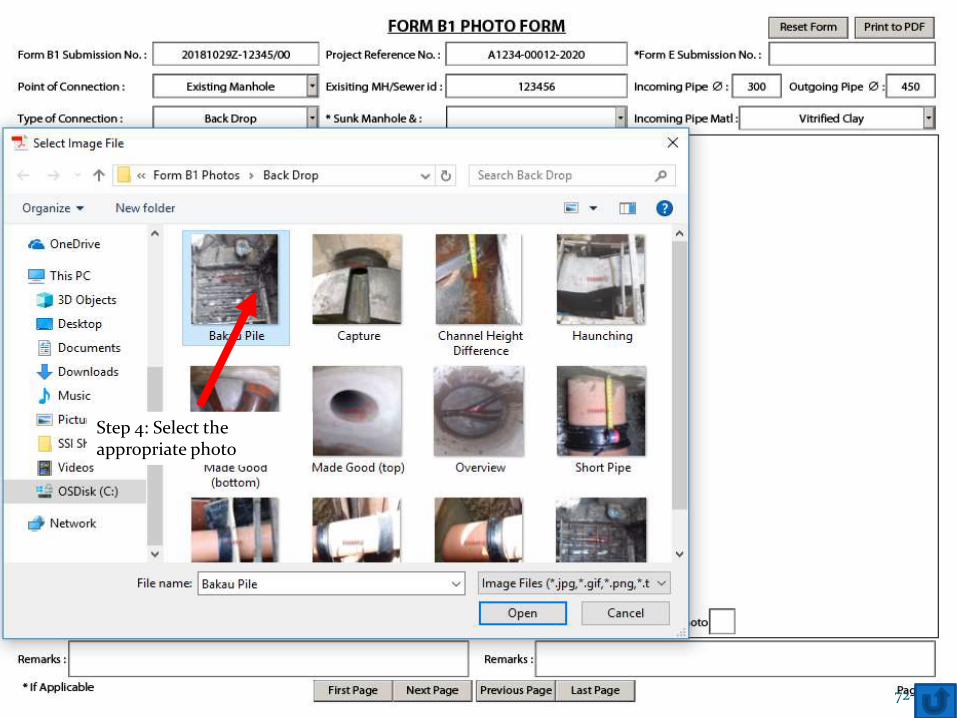
Step 4: Select the appropriate photo
73
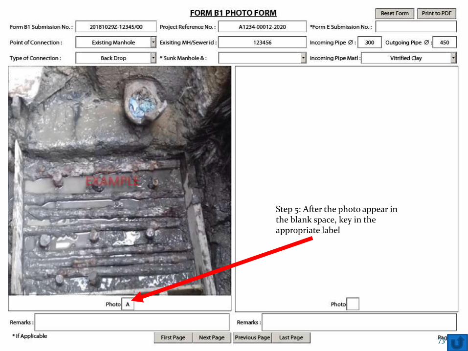
Step 5: After the photo appear in the blank space, key in the appropriate label
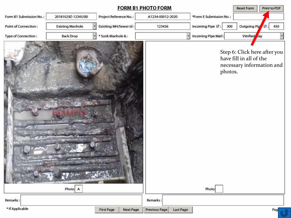
Step 6: Click here after you have fill in all of the necessary information and photos.
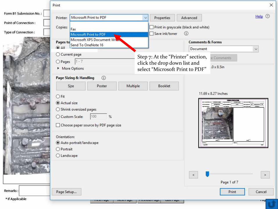
Step 7: At the “Printer” section, click the drop down list and select “Microsoft Print to PDF”
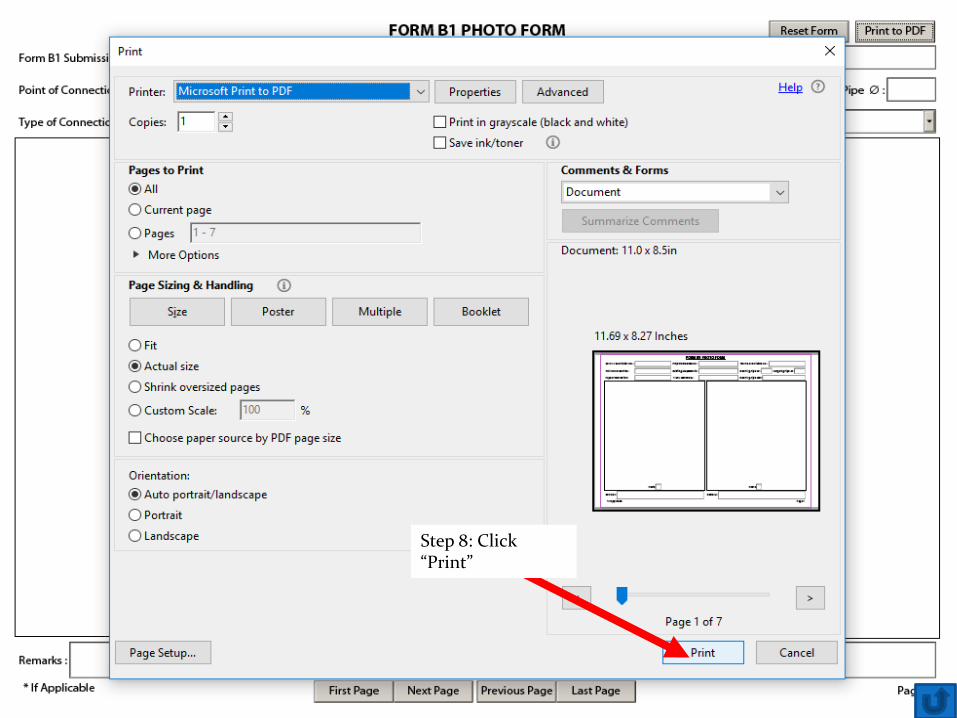
Step 8: Click “Print”
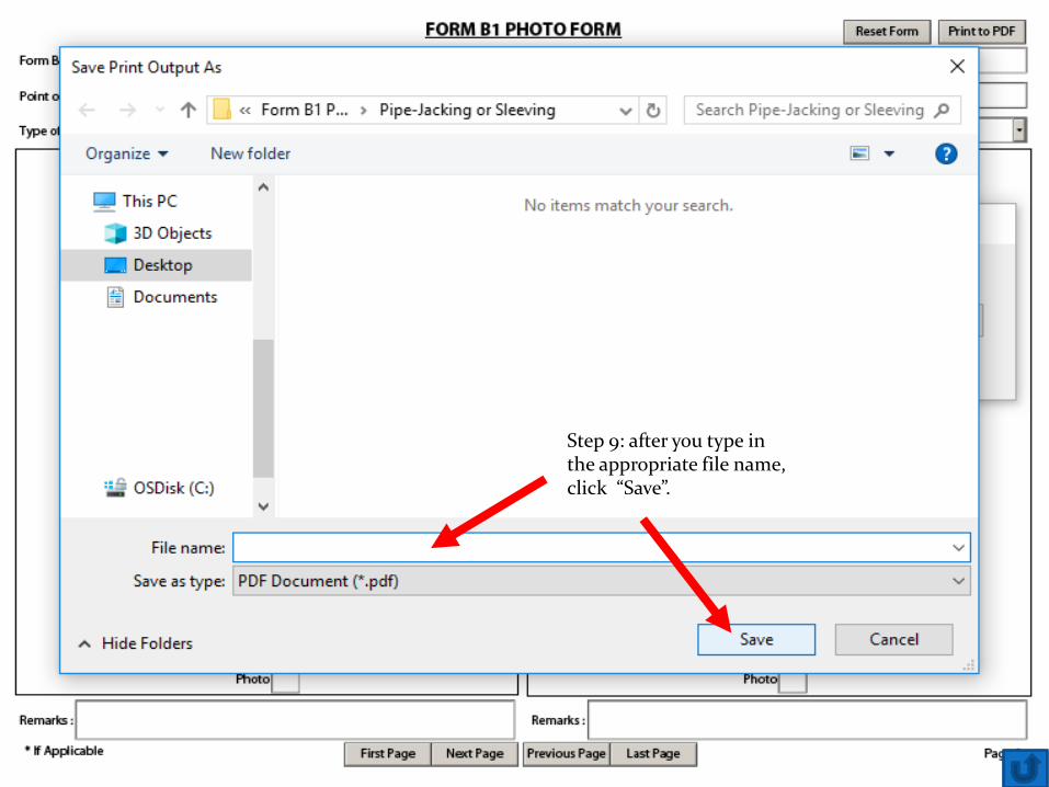
Step 9: after you type in the appropriate file name, click “Save”.
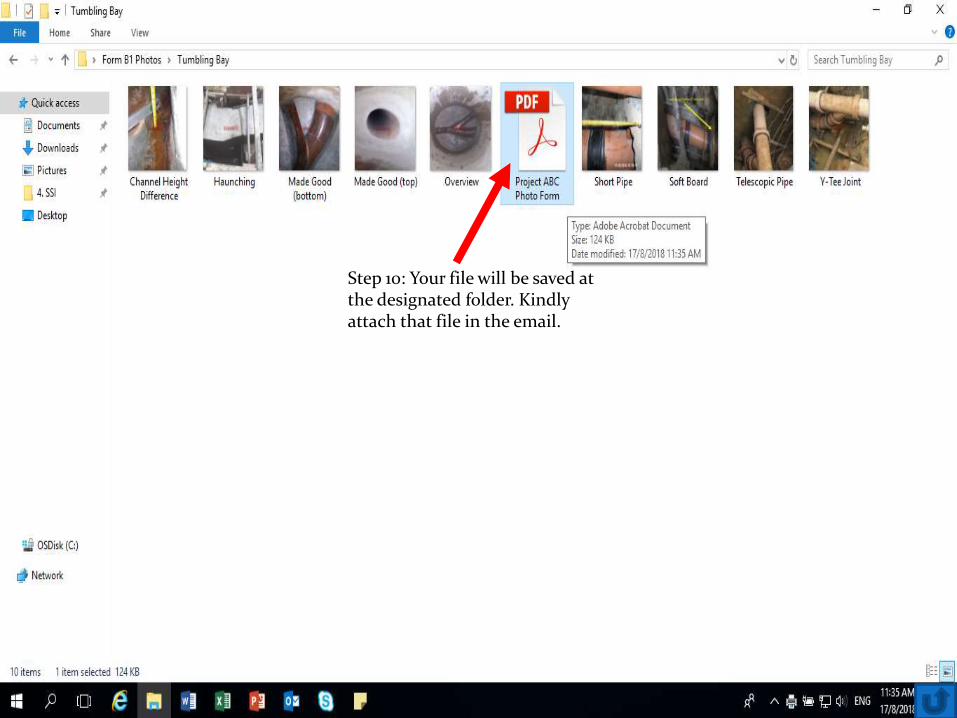
Step 10: Your file will be saved at the designated folder. Kindly attach that file in the email.
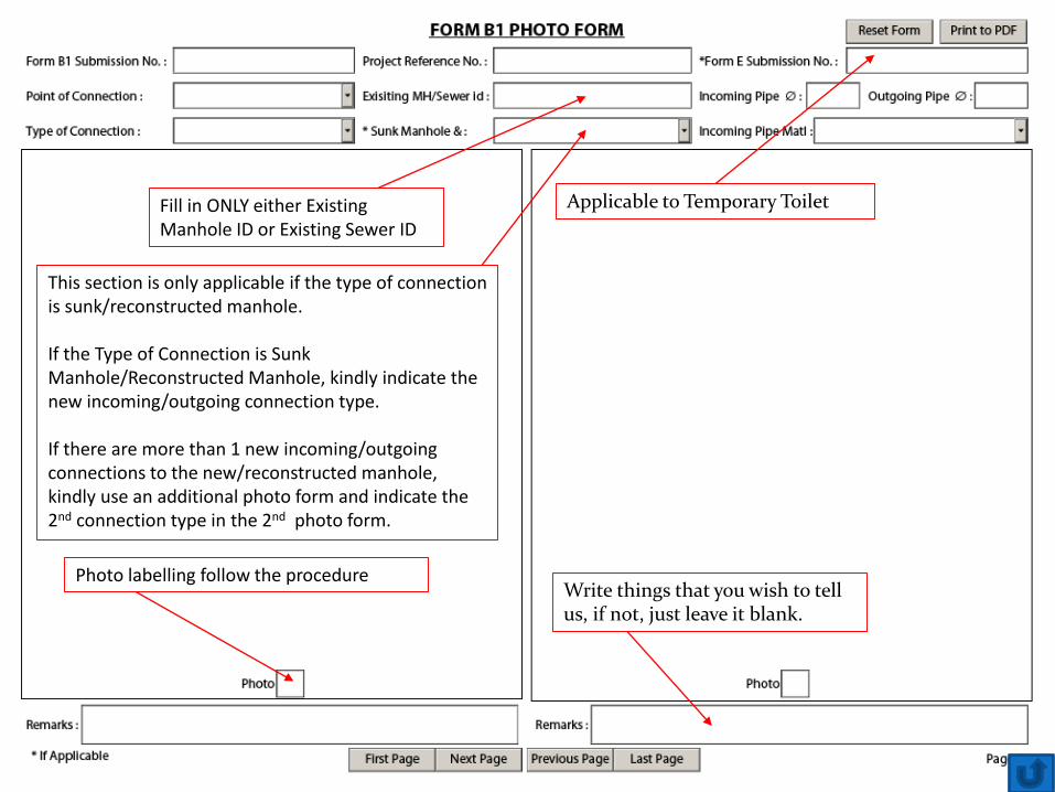
Fill in ONLY either Existing Manhole ID or Existing Sewer ID
This section is only applicable if the type of connection is sunk/reconstructed manhole.
If the Type of Connection is Sunk Manhole/Reconstructed Manhole, kindly indicate the new incoming/outgoing connection type.
If there are more than 1 new incoming/outgoing connections to the new/reconstructed manhole, kindly use an additional photo form and indicate the 2nd connection type in the 2nd photo form.
Photo labelling follow the procedure
Applicable to Temporary Toilet
Write things that you wish to tell us, if not, just leave it blank.
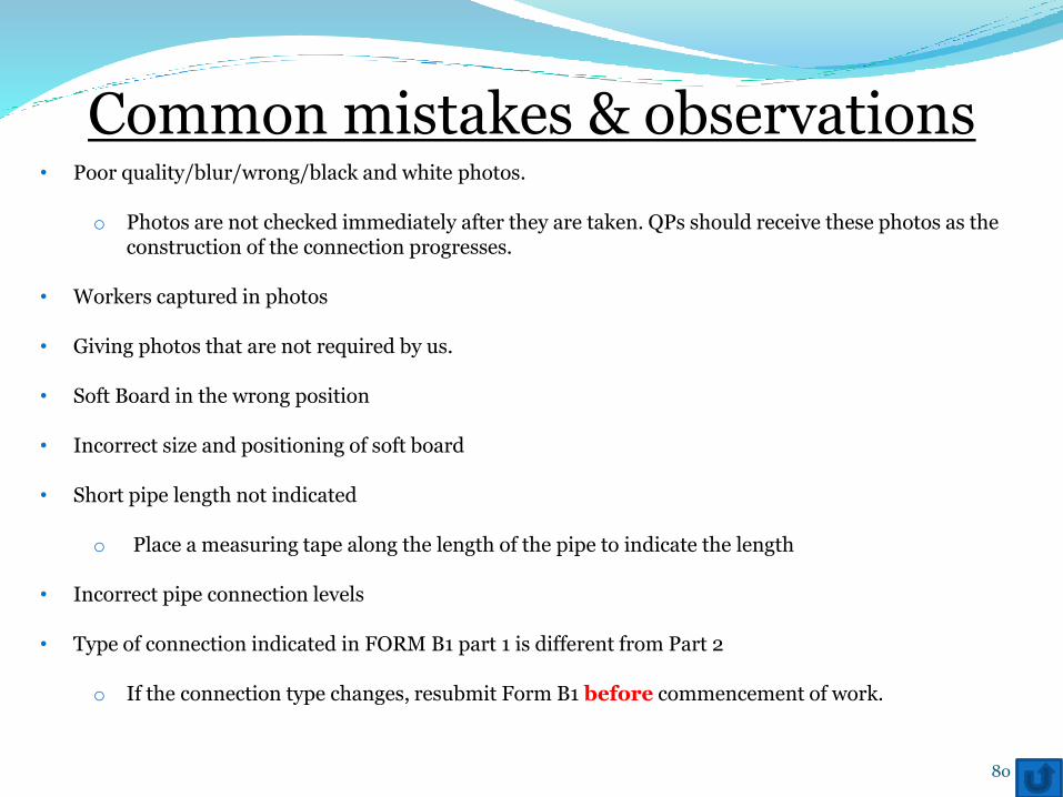
Common mistakes & observations• Poor quality/blur/wrong/black and white photos.
o Photos are not checked immediately after they are taken. QPs should receive these photos as the construction of the connection progresses.
• Workers captured in photos
• Giving photos that are not required by us.
• Soft Board in the wrong position
• Incorrect size and positioning of soft board
• Short pipe length not indicated
o Place a measuring tape along the length of the pipe to indicate the length
• Incorrect pipe connection levels
• Type of connection indicated in FORM B1 part 1 is different from Part 2
o If the connection type changes, resubmit Form B1 before commencement of work.
80

FAQ
• How do I make an appointment for consultation?
o Write in to [email protected]
Subject: Form B1 consultation
Provide 3 dates with time
E.g. 21/06/2017 @ 1400hrs, 23/06/2017 @ 0900hrs and 25/06/2017 @
1600hrs
81

END
82
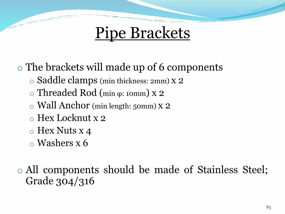
Pipe Brackets
o The brackets will made up of 6 components
o Saddle clamps (min thickness: 2mm) x 2
o Threaded Rod (min φ: 10mm) x 2
o Wall Anchor (min length: 50mm) x 2
o Hex Locknut x 2
o Hex Nuts x 4
o Washers x 6
o All components should be made of Stainless Steel;Grade 304/316
83
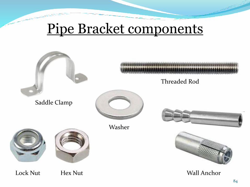
Saddle Clamp
Threaded Rod
Wall AnchorHex NutLock Nut
Washer
Pipe Bracket components
84
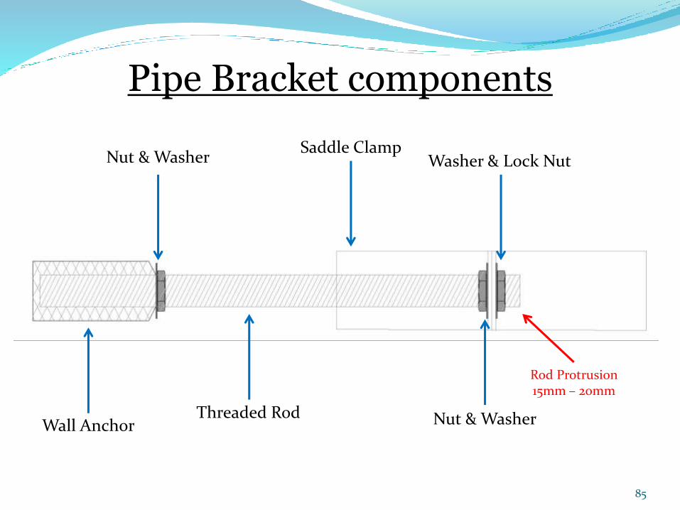
Washer & Lock Nut
Threaded Rod
Nut & Washer
Wall Anchor Nut & Washer
Saddle Clamp
Pipe Bracket components
Rod Protrusion15mm – 20mm
85
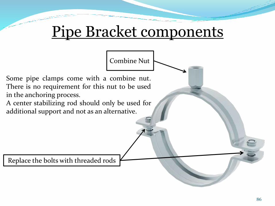
Some pipe clamps come with a combine nut.There is no requirement for this nut to be usedin the anchoring process.A center stabilizing rod should only be used foradditional support and not as an alternative.
Combine Nut
Replace the bolts with threaded rods
Pipe Bracket components
86
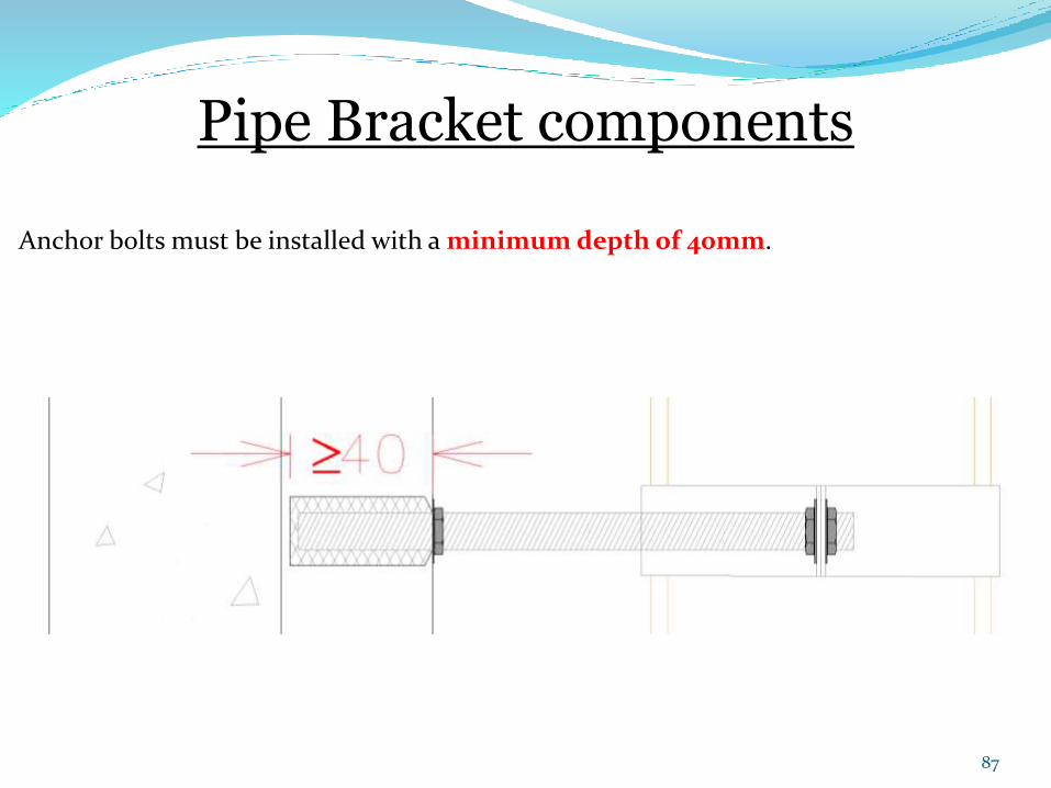
Anchor bolts must be installed with a minimumdepth of 40mm.
Pipe Bracket components
87
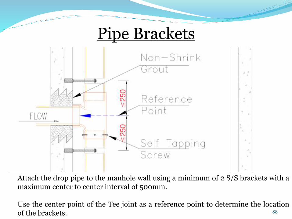
Pipe Brackets
Attach the drop pipe to the manhole wall using a minimum of 2 S/S brackets with amaximum center to center interval of 500mm.
Use the center point of the Tee joint as a reference point to determine the locationof the brackets. 88
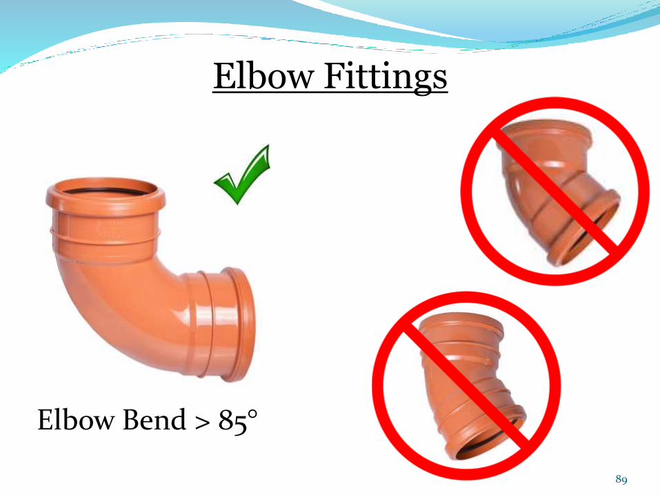
Elbow Bend > 85°
Elbow Fittings
89
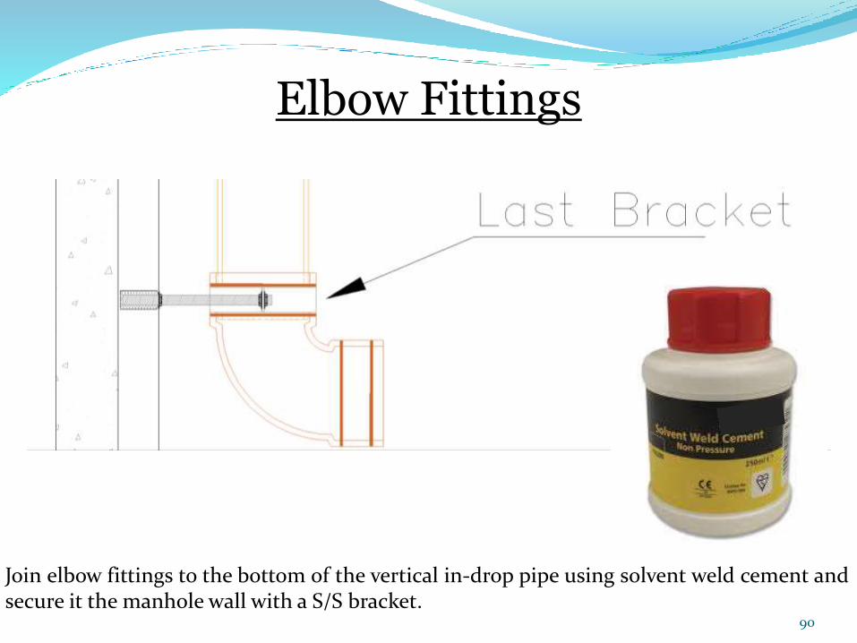
Join elbow fittings to the bottom of the vertical in-drop pipe using solvent weld cement andsecure it the manhole wall with a S/S bracket.
Elbow Fittings
90
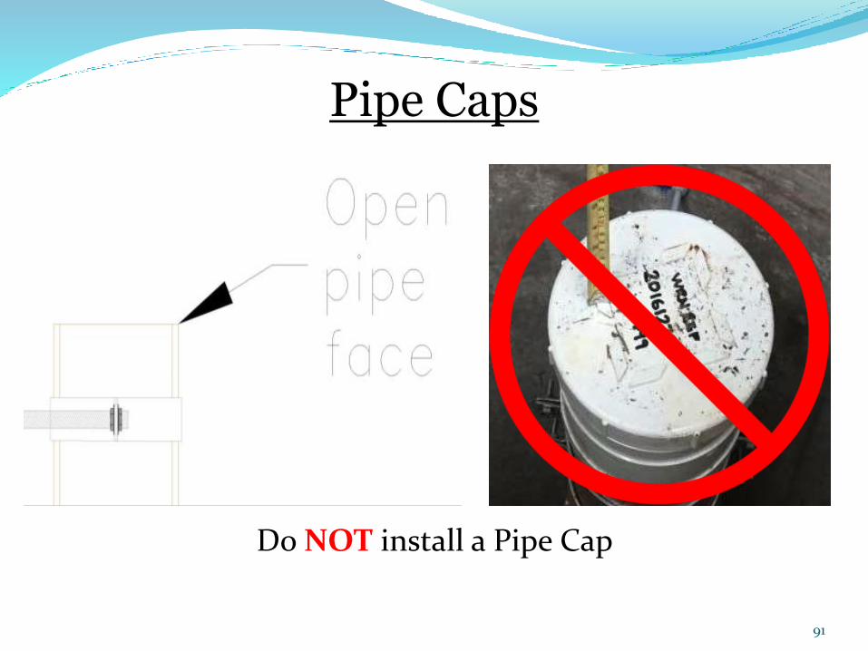
Do NOT install a Pipe Cap
Pipe Caps
91