foreword - teachrtec.com...
TRANSCRIPT

Disclaimer Statement
Contributions of many individuals and from written resources have collectively made this curriculum guide possible. The major authors, however, do not claim or guarantee that its contents will eliminate acts of malpractice or negligence. The responsibility to adhere to safety standards and best professional practices is the duty of the practitioners, teachers, students, and /or others who apply the contents of this document.
This guide was developed with federal Carl Perkins Act funds.
2005Career-Technical Education
North Carolina Department of Public Instruction
In compliance with federal law, including the provisions of Title IX of the Education Amendments of 1972, NC Public Schools does not discriminate on the basis of race, sex, religion, color, national or ethnic origin, age, disability, or military service in its policies, programs, activities, admissions or employment. Inquiries or complaints should be directed to the Office of Curriculum and School Reform Services, 6307 Mail Service Center, Raleigh NC 27699-6307. Telephone (919) 807-3761; Fax (919) 807-3767
i

FOREWORD
This course is focused on the principles, concepts, and the use of complex graphic tools utilized in the fields of architecture, structural systems, and constructional trades. Emphasis is placed on a study of architectural styles and the application of CAD tools in the creation of site plans, foundation plans, stair details, and interior elevation drawings. Mathematical, scientific, and visual design concepts are reinforced. Work-based learning strategies appropriate for this course are apprenticeship and cooperative education.
Skills in communication, mathematics, science, leadership, teamwork, and problem-solving are reinforced in this course. Job shadowing is an appropriate work-based learning strategy for this course. Hands-on work experience and SkillsUSA leadership activities provide many opportunities to enhance classroom instruction and career development.
This curriculum was developed as a resource for teachers to use in planning and implementing a competency-based instructional management drafting program in their school. These materials are tools used in the curriculum management process. Included are specific learning objectives, recommended activities, performance assessments, equipment list, facility specifications, a bibliography of reference media, and the names and addresses of media vendors.
It is our goal to provide the children of our state an education of the highest quality. As this guide reflects our goal of continuous improvement, we encourage you to communicate to us ways to improve the material within this publication. Your suggestions will be welcomed and appreciated.
ii
TABLE OF CONTENTS
PageSECTION I
Foreword . . . . . . . . . ii
Acknowledgments . . . . . . . . iv
Using the Curriculum Materials . . . . . . v
Course Blueprint . . . . . . . . viii
SECTION II – UNITS OF INSTRUCTION
Unit A Leadership Development . . . . . 1
Unit B Architectural Styles . . . . . . 6
Unit C Site Development . . . . . . 16 Unit D Foundation Design and Construction . . . . 32
Unit E Stair Design and Construction. . . . . 42
Unit F Advanced Kitchen and Bath Design. . . . . 54
SECTION III - APPENDICES
A. Bibliography / References . . . . . . 64
B. Vendor's Addresses for Texts, Literature, Software and Videos . 65
C. Equipment List . . . . . . . 66
D. Facility Design Specifications . . . . . 67
E. Curriculum Products Evaluation Form . . . . 69
iii

ACKNOWLEDGMENTSThe Division of Instructional and Accountability Services and the Trade and Industrial Education staff wish to give special thanks to the individuals who spent many hours revising the Drafting-Architectural III curriculum and test-item banks. The process included a review of international literature, review of suggestions offered by teachers and administrators from throughout the state, and many hours spent in constructive discussion and development.
The following individuals developed the Summer 2005 Drafting Architectural III blueprint, curriculum guide, and classroom and secure test-item banks:
Robin Migliorato Team Leader, Architectural Drafting Teacher New Bern High SchoolTony Bello Architectural Drafting Teacher Havelock High SchoolScott Marshall Architectural Drafting Teacher South View High SchoolCeleste Morton Architectural Drafting Teacher Scotland High SchoolBryant York Architectural Drafting Teacher Jacksonville High School
We would like to extend our gratitude and thanks to those who have contributed their time and effort to previous versions of the Drafting Architectural Curriculum. We appreciate their hard work. Finally, we would like to thank the teachers, directors, and others who have taken their time to critique our progress and offer suggestions during this process. Our work is better for their effort.
Tom Shown Consultant, Trade and Industrial Education, NCDPI
Rebecca Payne Section Chief, Industrial Technology and Human Services, NCDPI
Wandra Polk Director of Secondary Education, NCDPI
iv
USING THE CURRICULUM MATERIALS
Purpose
The Drafting Architectural III Curriculum Materials were developed as a resource for teachers to use in planning and implementing a competency-based instructional management drafting program in their school. These materials are tools used in the curriculum management process.
Curriculum Guide Description
Drafting Architectural III was designed to be a one unit course (135-180 hours of instruction). This course is focused on the principles, concepts, and use of complex graphic tools utilized in the field of architecture, structural systems, and construction trades. Emphasis is placed on the application of CAD tools in the creation of site plans, foundation plans, stair detail plans, and interior elevation drawings. Mathematics, science, and visual design concepts are reinforced. Work-based learning strategies appropriate for this course are apprenticeship and cooperative education. Hands-on work experiences and SkillsUSA-VICA leadership activities provide many opportunities to enhance classroom instruction and career development.
General Instruction
Drafting Architectural III may be taught using individualized, whole class or small team instruction, or a combination of each. Regardless of the method used, it is essential that the activities reflect the competencies and objectives of this course.
The course demands much from the student and teacher in terms of its complexity and the brevity of time in which the materials are to be mastered. Because of time limitations and the amount of material to be covered, one cannot teach objectives as discrete units of instruction. Objectives must be taught concurrently within the larger context of activities. This allows for the efficient use of time as well as reflecting good pedagogy.
Blueprint
The blueprint (See the Drafting Architectural III Blueprint on the following pages) lists the competencies that the student is to achieve. Competencies are mastered when a student masters the objectives which make up the competency. Course weight is the degree of importance given to each objective in relation to the entire course of study. This in turn will determine the number of test-items per objective on any test developed by the State Department of Education. For example, on a state EOC 100 item assessment, a cognitive objective having a value of 10% will have 10 test-items representing that objective.
Units of Instruction
The Units of Instruction section is designed to give the teacher detailed information directly correlated to the blueprint and test-item bank. It attempts to explain in more detail what information or behavior the student is expected to know or do. Unless a student has an individualized education plan, he/she will be expected to become competent in all areas covered within this course at the end of 135-180 hours of instruction. It is important to recognize that Unit sequencing DOES NOT IMPLY SEQUENCE OF INSTRUCTION. Therefore, information within the course should be used where it makes sense and best fits. Using information from a variety of competencies and objectives are used when it is most pedagogically sound.
Leadership Development Unit
v

Objective 301.01 covers preparing and delivering a technical presentation with visual aids. This section is particularly useful to those teachers and students who participate in SkillsUSA-VICA. Objective 301.02 covers preparing and delivering extemporaneous technical presentations. This section is also useful to those teachers and students who participate in SkillsUSA-VICA.
Architectural Styles UnitObjective 302.01 introduces terms related to architectural styles.Objective 302.02 explains concepts associated with styles of residential architecture.Objective 302.03 requires students to produce illustrations or presentations of various architectural styles. Rubrics are included for performance assessment.
Site Development UnitObjective 303.01 introduces students to terms and definitions related site development.Objective 303.02 acquaints students with considerations for developing a site plan.Objective 303.03 explains symbols and features on site plans.Objective 303.04 demonstrates the process for producing site plans.Objective 303.05 requires students to draw site plan for a residential structure. A rubric is included for this performance assessment.
Foundation Design and Construction UnitObjective 304.01 introduces students to terminology related to foundation design and construction.Objective 304.02 demonstrates the process for designing foundation plans and details.Objective 304.03 requires students to draw a foundation plan. A rubric is included for this performance assessment.
Stair Design and Construction UnitObjective 305.01 introduces students to terms and definitions related to stair design and construction.Objective 305.02 identifies components and standards used to construct a stair system.Objective 305.03 explains calculations for stair design and construction.Objective 305.04 requires students to draw stair plans and details. A rubric is included for this performance assessment.
Advanced Kitchen and Bath UnitObjective 306.01 introduces students to terms and concepts related to kitchen and bath design.Objective 306.02 explains elements of kitchen and bath design.Objective 306.03 demonstrates the process for developing kitchen and bath elevations.Objective 306.04 requires students to draw interior kitchen and bath elevations. A rubric is included for this performance assessment.
vi
Bibliography/References (Appendix A)
This section provides the names, authors, and publishers of the texts listed within the Units of Instruction section.
Vendor’s Addresses for Texts, Literature, and Video (Appendix B)
We have included a partial listing of where and whom to contact for obtaining texts, literature, software, and videos.
Equipment List (Appendix C)
The equipment list (updated as of this printing, Summer 2005), gives the minimum number of tools, equipment, and software necessary for the instruction of Drafting Architectural III.
Facility Design Specifications (Appendix D)
These are facility design specifications for the Drafting-Architectural II and Drafting-Architectural III programs.
Drafting Architectural III Curriculum Products Evaluation Form (Appendix E)
Included in this guide is an evaluation form. We sincerely want your thoughtful suggestions for improving the curriculum products. The test-item bank and many of the improvements within this guide are the result of teachers who have taken the time to make suggestions for improvement. Please take the time to respond to us on ways to improve our work.
Final Comment
If you have any questions regarding any aspect of this course, curriculum guide, test-item bank, equipment, literature, or software needs, please call or write Tom Shown 919.870.3880, [email protected]
vii
VoCATSCourse Blueprints
Trade and Industrial Education
7963 Drafting - Architectural III
Public Schools of North CarolinaState Board of Education Department of Public Instruction
Office of Instructional and Accountability ServicesDivision of Instructional Services
Raleigh, North CarolinaSummer 2005
Special thanks to the following educators and business people who reviewed and approved this blueprint for technical content and appropriateness for the industry.
Robin Migliorato – New Bern High School
Tony Bello – Havelock High School
Scott Marshall – South View High School
Celeste Morton – Scotland High School
Rhonda Myers – Northern Durham High School
Bryant A. York – Jacksonville High School
This blueprint has been reviewed by business and industry representatives for technical content and appropriateness for the industry. Contact [email protected] for more information.
viii

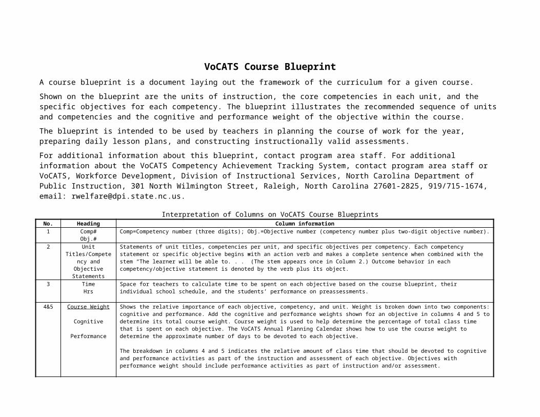
VoCATS Course BlueprintA course blueprint is a document laying out the framework of the curriculum for a given course.
Shown on the blueprint are the units of instruction, the core competencies in each unit, and the specific objectives for each competency. The blueprint illustrates the recommended sequence of units and competencies and the cognitive and performance weight of the objective within the course.
The blueprint is intended to be used by teachers in planning the course of work for the year, preparing daily lesson plans, and constructing instructionally valid assessments.
For additional information about this blueprint, contact program area staff. For additional information about the VoCATS Competency Achievement Tracking System, contact program area staff or VoCATS, Workforce Development, Division of Instructional Services, North Carolina Department of Public Instruction, 301 North Wilmington Street, Raleigh, North Carolina 27601-2825, 919/715-1674, email: [email protected].
Interpretation of Columns on VoCATS Course BlueprintsNo. Heading Column information1 Comp#
Obj.#Comp=Competency number (three digits); Obj.=Objective number (competency number plus two-digit objective number).
2 Unit Titles/Competency
and Objective Statements
Statements of unit titles, competencies per unit, and specific objectives per competency. Each competency statement or specific objective begins with an action verb and makes a complete sentence when combined with the stem “The learner will be able to. . .” (The stem appears once in Column 2.) Outcome behavior in each competency/objective statement is denoted by the verb plus its object.
3 TimeHrs
Space for teachers to calculate time to be spent on each objective based on the course blueprint, their individual school schedule, and the students’ performance on preassessments.
4&5 Course Weight
Cognitive
Performance
Shows the relative importance of each objective, competency, and unit. Weight is broken down into two components: cognitive and performance. Add the cognitive and performance weights shown for an objective in columns 4 and 5 to determine its total course weight. Course weight is used to help determine the percentage of total class time that is spent on each objective. The VoCATS Annual Planning Calendar shows how to use the course weight to determine the approximate number of days to be devoted to each objective.
The breakdown in columns 4 and 5 indicates the relative amount of class time that should be devoted to cognitive and performance activities as part of the instruction and assessment of each objective. Objectives with performance weight should include performance activities as part of instruction and/or assessment.
6 TypeBehavior
Classification of outcome behavior in competency and objective statements. (C=Cognitive; P=Psychomotor; A=Affective)
7 IntegratedSkill Area
Shows links to other academic areas. Integrated skills codes: A=Arts; C=Communications; CD=Career Development; CS=Information/Computer Skills; H=Health and Safety; M=Math; SC=Science; SS=Social Studies.
8 CoreSupp
Designation of the competencies and objectives as Core or Supplemental. Competencies and objectives designated "Core" must be included in the Annual Planning Calendar and are assessed on the statewide pre- and postassessments..
Career-Technical Education conducts all activities and procedures without regard to race, color, creed, national origin, gender, or disability. The responsibility to adhere to safety standards and best professional practices is the duty of the practitioners, teachers, students, and/or others who apply the contents of this document

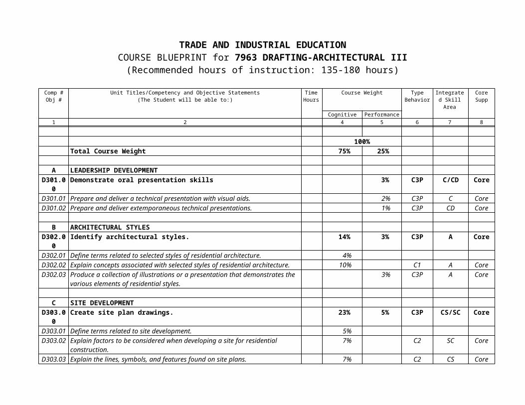
TRADE AND INDUSTRIAL EDUCATIONCOURSE BLUEPRINT for 7963 DRAFTING-ARCHITECTURAL III
(Recommended hours of instruction: 135-180 hours)
Comp #Obj #
Unit Titles/Competency and Objective Statements(The Student will be able to:)
Time Hours
Course Weight TypeBehavior
Integrated Skill Area
CoreSupp
Cognitive Performance1 2 4 5 6 7 8
100%Total Course Weight 75% 25%
A LEADERSHIP DEVELOPMENTD301.00 Demonstrate oral presentation skills 3% C3P C/CD CoreD301.01 Prepare and deliver a technical presentation with visual aids. 2% C3P C CoreD301.02 Prepare and deliver extemporaneous technical presentations. 1% C3P CD Core
B ARCHITECTURAL STYLES
D302.00 Identify architectural styles. 14% 3% C3P A CoreD302.01 Define terms related to selected styles of residential architecture. 4%D302.02 Explain concepts associated with selected styles of residential architecture. 10% C1 A CoreD302.03 Produce a collection of illustrations or a presentation that demonstrates the
various elements of residential styles.3% C3P A Core
C SITE DEVELOPMENTD303.00 Create site plan drawings. 23% 5% C3P CS/SC CoreD303.01 Define terms related to site development. 5%D303.02 Explain factors to be considered when developing a site for residential
construction.7% C2 SC Core
D303.03 Explain the lines, symbols, and features found on site plans. 7% C2 CS CoreD303.04 Develop a site plan drawing. 4% C3P CS CoreD303.05 Draw a site plan for a residential structure. 5%
D FOUNDATION DESIGN AND CONSTRUCTIOND304.00 Design and draw foundation plans. 17% 5% C3P CS CoreD304.01 Identify terms and definitions relating to foundation design and construction. 3%D304.02 Design footings, foundation walls, girders, piers, ventilation, and slab
floor/foundations.14% C3 CS Core

Comp #Obj #
Unit Titles/Competency and Objective Statements(The Student will be able to:)
Time Hours
Course Weight TypeBehavior
Integrated Skill Area
CoreSupp
Cognitive Performance1 2 4 5 6 7 8
D304.03 Design and draw a foundationsystem. 5% C3P CS Core
E STAIR DESIGN AND CONSTRUCTIOND305.00 Design and draw a stair system. 11% 5% C3P C/A/M/CS CoreD305.01 Identify terms and definitions relating to stair design and construction. 3%D305.02 Identify the parts and standards used to construct a stair system. 4% C2 C CoreD305.03 Explain the calculations for rise, run, total rise, total run, and floor cutout. 4% C2 C CoreD305.04 Draw plans for stair construction. 5% C3P CS Core
F ADVANCED KITCHEN & BATH DESIGND307.00 Design and draw kitchen cabinet layouts. 10% 4% C3P CS/A/C CoreD306.01 Identify terms and concepts related to kitchen and bath design. 2%D306.02 Explain the elements of kitchen and bath design. 5% C1 C CoreD306.03 Develop plans for kitchen cabinet drawings. 3% C3P CS/A CoreD306.04 Draw interior elevation plans for kitchens and baths. 4%

Architecture III Summer 2005
UNIT A
Leadership Development
1
Architecture III Summer 2005
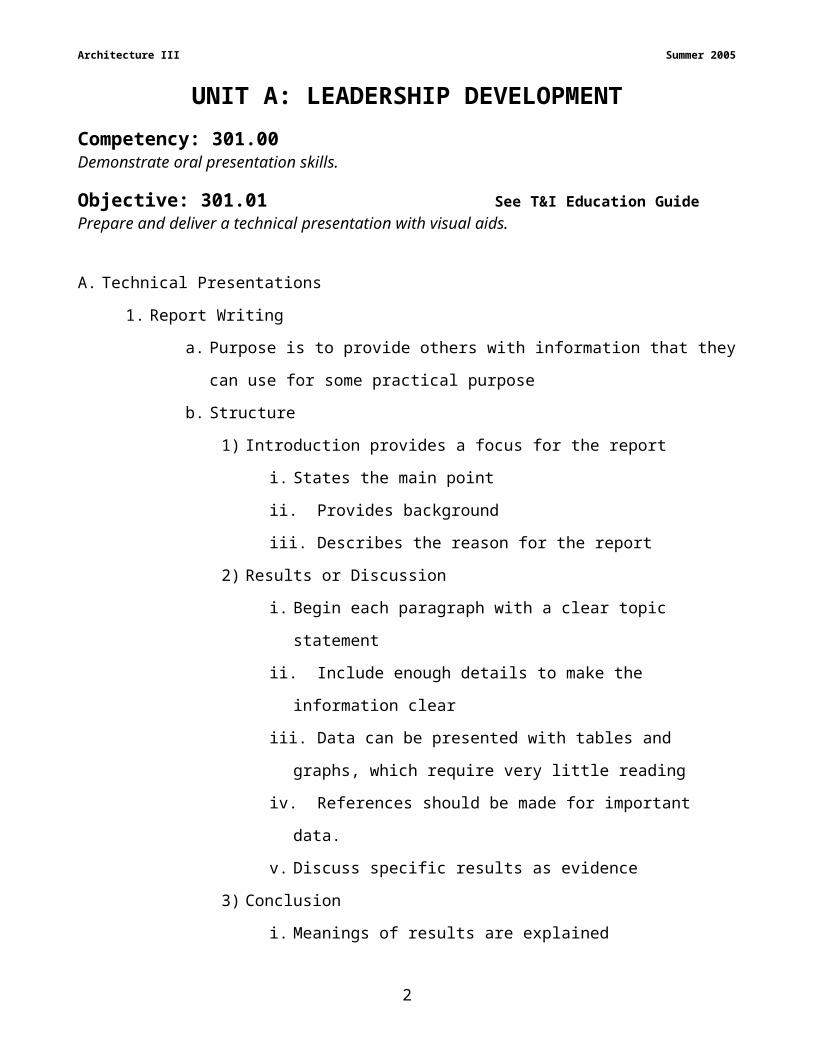
UNIT A: LEADERSHIP DEVELOPMENTCompetency: 301.00Demonstrate oral presentation skills.
Objective: 301.01 See T&I Education GuidePrepare and deliver a technical presentation with visual aids.
A. Technical Presentations
1. Report Writing
a. Purpose is to provide others with information that they can use for some
practical purpose
b. Structure
1) Introduction provides a focus for the report
i. States the main point
ii. Provides background
iii. Describes the reason for the report
2) Results or Discussion
i. Begin each paragraph with a clear topic statement
ii. Include enough details to make the information clear
iii. Data can be presented with tables and graphs, which require
very little reading
iv. References should be made for important data.
v. Discuss specific results as evidence
3) Conclusion
i. Meanings of results are explained
ii. Conclusions should focus on answering the original question
4) Recommendations may be made or omitted if there are none
5) References give credit to sources of information.
2. Visual aids can provide more information than written words, they should be part
of the message rather than a supplement.
a. Wrap text around images
b. Crop pictures
c. Use clipart effectively
2

Architecture III Summer 2005
d. Use bullets effectively
B. Multimedia Report/Presentation
1. Determine what is expected out of the presentation
2. Evaluate the time allotted for the presentation
3. Consider the size of the audience and physical layout of the room to determine
visibility
4. Use restraint, do not make the presentation overly complex
5. Focus on the Goal
a. Establish an objective
b. Choose a presentation theme
1) Dramatic
2) Direct
3) Easy to visualize
c. Consider a small graphic that ties all visual aids together
6. Organize Thoughts
a. An audience generally remembers 2 or 3 points in a presentation
b. Develop an outline with word-processing software that may be transferred
to presentation software
c. Develop your thoughts before you create visuals
7. Creating Visuals
a. Plan 3-5 slides for each major concept
b. Use only one main concept per slide
c. Limit each slide to 5 or fewer bullets
d. Avoid too many objects per slide
e. Make text readable
1) Font
2) Color
3) Size should be at least point 24
f. Use short, to-the-point phrases rather than sentences
g. Use the same font, background, and colors throughout
h. Limit slide transition effects
i. Keep color contrasts high
3
Architecture III Summer 2005
j. About 4% of men are red/green colorblind
k. Use graphics to make the presentation interesting
l. Add text to autoshapes to make the information stand out
m. Create 3D and shadow effects
n. Use animation appropriately
8. Do not read information
9. Do not memorize the presentation
a. Cuts down spontaneity
b. Limits ability to interact with the audience
c. Can get lost
d. Become very familiar with the information by rehearsing
10.Go through the process prior to presenting to an audience
a. Identify equipment problems
b. Increases confidence
c. Develop backup plans in case equipment fails
11.Show time
a. Arrive early to check out equipment and/or make last minute changes
b. Relax by taking deep breaths
c. Keep a sense of humor; do not overreact
d. Keep distractions to a minimum
4

Architecture III Summer 2005
UNIT A: LEADERSHIP DEVELOPMENTCompetency: 301.00Demonstrate oral presentation skills.
Objective: 301.02 See T&I Education GuidePrepare and deliver extemporaneous technical presentations.
Review the Drafting-Architectural III test-item bank for the specific information which students are expected to know and do for this section.
5

Architecture III Summer 2005
UNIT B
Architectural Styles
6
Architecture III Summer 2005
UNIT B: ARCHITECTURAL STYLES
Competency: 302.00Identify architectural styles.
Objective: 302.01 R1 pgs.155-168Define terms related to selected styles of residential architecture.
Terms and Definitions1. Post – A vertical wood structural member usually 4x4 or larger
2. Lintel – A horizontal steel member used to provide support for masonry over an opening
3. Arch – An inclined ceiling area
4. Vault – An inclined ceiling area
5. Column – A vertical structural support, usually round and made of steel
6. Clapboards – A tapered board used for siding that overlaps the board below it
7. Parapet – A position of wall that extends above the edge of the roof
8. Balcony – A deck or patio that is above ground level
7
Architecture III Summer 2005
UNIT B: ARCHITECTURAL STYLESCompetency: 302.00Identify architectural styles.
Objective: 302.02 R1 pgs.155-168Explain concepts associated with selected styles of residential architecture.
A. Development of architectural styles
1. Influences
a. Climate
b. Available materials
c. Building techniques available to the time period
2. Styles
a. Few structures exemplify any particular style
b. Categorized by most common and significant features
c. Transitions
i. Occur from one time period to another
ii. Occur from one geographical origin to another
3. Significant historical architectural developments
a. Post and lintel
b. Arch
c. Vault
d. Dome
4. Influences on early American architecture
a. European styles serve as a basis for the development of American styles
b. England, France, Spain, and Italy provided the most significant influences
c. Structural influences represented
i. Available materials
ii. Climate
iii. Settlers’ backgrounds
d. Style names origin
i. Geographical region
ii. Shape of the structure
8
Architecture III Summer 2005
iii. Time period
B. Elements of Design
1. Line
a. Offers a sense of direction and/or movement in design of structure
b. Relates a structure to the site and natural surroundings
c. Curved lines soften appearance
d. Horizontal lines minimize height and maximize width
e. Vertical lines create an illusion of height and strength
f. Diagonal lines create a sense of transition
2. Form
a. Rectangles, squares, circles, ovals, ellipses
b. Should be dictated by function
c. Used to accent specific features
3. Color
a. Aides in distinguishing between exterior materials and accent shapes
b. Described in terms of hue, value, and intensity
i. Hue represents what is typically considered the color
ii. Value is the darkening or lightening of a hue
iii. Intensity is the brightness or strength of a specific color
4. Texture
a. The roughness or smoothness of a surface
i. Rough surfaces
1. Feeling of strength
2. Feeling of security
ii. Smooth surfaces
1. Illusion of increased height
2. Reflect more light
3. Make colors seem brighter
b. Important in selecting materials to complete a structure
5. Rhythm
a. Repetitive element provides rhythm; leads the eye through the design
b. Created with gradual change in materials, shape, and color
9

Architecture III Summer 2005
6. Balance
a. The relationship between areas of the structure and an imaginary center
line
b. Formal balance is symmetrical.
c. Informal balance is nonsymmetrical.
7. Proportion
a. Relates to size and balance
b. Affects the way a residence relates to its environment
c. Considered in design of exterior and interior of a structure
8. Unity
a. Relates to rhythm, balance, and proportion
b. Ties a structure together with a common design
c. Avoid features that appear “tacked on”
C. Floor Plan Styles
1. Single-level residences
a. Among the most common styles
b. Provide stair-free access
c. Simple to maintain
d. Can be used with a variety of exterior styles
2. Split-level residences
a. Attempt to combine features of one and two-story structures
b. Best suited to sloping sites
c. Construction is greater due to increased foundation costs
d. May be split from side to side of front to back
3. Two-story residences
a. Provide numerous options for families where stairs are not a problem
b. Living and sleeping areas are easily separated.
c. Minimal land is used for building site.
d. Provide maximum building area at a lower cost per square foot
i. Less foundation material
ii. Fewer exterior walls
iii. Smaller roof
10

Architecture III Summer 2005
4. Dormer style
a. Two levels with upper level about half of first floor square footage
b. Best suited to an exterior style that incorporates a steep roof
c. Dormer level is formed in attic-like area
d. Offers many of the same economic features of a two-story home
5. Multi-level layouts
a. Offer endless possibilities for floor levels
b. Site topography and owners’ living habits dictate style
c. Cost exceeds all other styles
D. Exterior styles
1. Georgian style
a. Exemplifies basic style modified throughout the colonies in response to
available material and the weather
b. Follows classical principles of design used by ancient Greeks
c. Principles of form and symmetry are most evident in the front elevation.
d. Entry is centered on the wall with equally spaced windows placed on each
side
e. Usually covered with a columned porch and a doorway trimmed with carved
wood detailing
f. In Southern homes, most of the exterior is built of brick
g. While in northern homes wood siding is the major covering
2. Saltbox style
a. Common modification of the Georgian style
b. Maintained the symmetry of the Georgian style without much of the
detailing
c. Two-story structure at the front that tapers to a one-story at the rear
d. Windows generally have shutters that protect against winter winds
3. Garrison style
a. Combines saltbox and Georgian style with construction methods of log
buildings
b. Originally modeled after the lookout structures of early forts
c. The upper level extends past the lower level
11

Architecture III Summer 2005
d. Heavy timbers supported the overhang
4. Cape Cod style
a. A one level with a steep roof to allow an upper-floor level formed throughout
the center of the house
b. Dormers are placed on the front side of the roof to make the second story
habitable.
c. Windows are symmetrical and shuttered on the lower level.
5. Federal style
a. Combines Georgian with classical Roman and Greek styles
b. Built of wood or brick
c. A high, covered entry porch or portico with Greek-style columns are
centered over the front door
d. Often, the door has arched trim
e. Windows are capped with a projected pediment
6. Greek Revival style
a. Classic proportions and decorations of classical Greek architecture
b. Large, rectangular, and very “boxlike”
c. A two-story portico with a low, sloped gable roof supported on Greek
columns is centered on the residence to add decoration
7. Southern Colonial style
a. Similar to Georgian style, with symmetrical features
b. Also referred to as plantation-style
c. Usually has a flat, covered porch extending the length of the house as
protection from the sun
8. English-style
a. Features an unsymmetrical layout
b. Walls are constructed of stone, brick, or heavy timber and plaster
c. Window glass is often diamond-shaped
9. Dutch colonial style
a. Many features of homes already described, with a different roof style
b. Features a gambrel roof (barn roof)
c. Roof made of two levels
12

Architecture III Summer 2005
1) Lower level
i. Very steep
ii. Serves as walls for the second floor
2) Upper area of the roof is the traditional gable roof
10.French colonial style
a. Differs in the roof design
b. Roof is similar to the gambrel with a steep lower roof
c. Uses a hipped or mansard roof to hide the upper floor area
d. Single-level French manors
i. Originally found in the northern states
i. Rectangular homes with a smaller wing on each side
ii. Mansard roofs used most often, but hip roofs also seen
11.French Normandy style
a. Multilevel and framed with brick, stone or wood, and plaster
b. Roof is gable or hip style
c. Circular turret is near the center of the home
12.French plantation style
a. Two full floors
b. Wraparound porch
c. Covered with a hip roof
13.Spanish colonial style
a. Built of adobe or plaster
b. Usually one story
c. Arches and tiled roofs distinguish the style
d. Timbers frame a flat or very low-pitched roof
e. Windows have grills or spindles and balconies with wrought-iron railings
14.Farmhouse style
a. Two-story construction
b. Little or no trim or detail work
c. Surrounded by a covered porch
15.Ranch style
a. Originated in the Southwest
13

Architecture III Summer 2005
b. Defined by a single-story rambling layout
c. Roof is low-pitched with a large overhang
d. Originally, the major exterior materials were stucco or adobe
16.Victorian and Queen Anne styles
a. Irregularly shaped floor plans
b. Ornate detailing
17.Contemporary, or modern styles
a. Do not denote any special style of home
1) Designed to meet a wide variety of needs and/or reflect the lifestyle of
the owner
2) Often, owners prefer the traditional exterior, but rarely would the
traditional floor plan be desirable
14
Architecture III Summer 2005
UNIT B: ARCHITECTURAL STYLESCompetency: 302.00Identify architectural styles.
Objective: 302.03 R1, Pgs.155-168Produce a collection of illustrations or a presentation that demonstrates the various elements of residential styles.
Students may do one or more of the following:
A. Photograph local houses or elements of local buildings
1. Use a digital camera or scan photos
2. Use MS PowerPoint or similar software to present information
B. Prepare and present a technical demonstration of elements of selected Architectural
styles
1. Illustrations may come from home magazines or plan books
2. Identify various features that give the house its style
C. Make a portfolio of sketches of various architectural elements
1. Sketches may be isometric or perspective
2. Use local structures
3. Identify the style with associated elements
D. Create a technical presentation with illustrations on the following:
1. The Influence of Technology on Architecture
2. The Influence of Climate on Architecture
3. The Influence of Geography on Architecture
15
Architecture III Summer 2005
UNIT C
Site Development
16

Architecture III Summer 2005
UNIT C: SITE DEVELOPMENT
Competency: 303.00Create site plan drawings.
Objective: 303.01Define terms related to site development.
R1 189-233, 243-249, 256R2 51-57, 217-230
Terms and Definitions
1. Aggregrate – Stone, gravel, cinder, or slag used as one of the components of
concrete
2. Appraisal – The estimated value of a piece of property
3. Backfill – Earth, gravel, or sand placed in the trench around the footing and stem wall
after the foundation has cured
4. Benchmark – A reference point used by surveyors to establish grades and
construction heights
5. Building Code – Legal requirements designed to protect the public by providing
guidelines for structural, electrical, plumbing, and mechanical areas of a structure
6. Building Line – An imaginary line determined by zoning departments to specify on
which area of a lot a structure may be built
7. Catch basin – An underground reservoir for water drained from a roof before it flows
to a storm drain
8. Compression – A force that crushes or compacts
9. Contours – A line that represents land formations
10.Contractor – The manager of a construction project, or one specific phase of it
11.Control point survey – A survey method that establishes elevations that is recorded on
a map
12.Easement – An area of land that cannot be built upon because it provides access to a
structure or to utilities, such as power or sewer
13.Fill – Material used to raise an area for construction; typically gravel or sand is used to
provide a raised, level building area
14.Grading – The moving of soil to effect the elevation of land at a construction site
17

Architecture III Summer 2005
15. International Residential Code (IRC) – A national building code for one- and two-
family dwelling
16.Plat – A parcel of land
17.Point-of-beginning – Fixed location on a plot of land where the survey begins
18.Profile – Vertical section of the surface of the ground, and/or of underlying earth that
is taken along any desired fixed line
19.Radial survey – A survey method used to locate property corners, structures, natural
features, and elevation points
20.Rebar – Reinforcing steel used to strengthen concrete
21.Retaining Wall – A masonry wall supported at the top and bottom, designed to resist
soil loads
22.Setback – The minimum distance required between the structure and the property line
23.Site Orientation – Placement of a structure on a property with certain environmental
and physical factors taken into consideration
24.Stress – A live or dead load acting on a structural member; stress results as the fibers
of a beam resist an external force
25.Survey map – Map of a property showing its size, boundaries, and topography
26.Swale – A recessed area formed in the ground to help divert ground water away from
a structure
27.Tamp – To compact soil or concrete
28.Topography – Physical description of land surface showing its variation in elevation
and location of features such as rivers, lakes, or towns
29.Zoning – An ordinance that regulates the location, size, and type of a structure in a
building zone
18

Architecture III Summer 2005
UNIT C: SITE DEVELOPMENT
Competency: 303.00Create site plan drawings.
Objective: 303.02Explain factors to be considered when developing a site for residential construction.
R1 189-233, 243-249, 256R2 51-57, 217-230
A. Site Considerations
1. Price range of any house in the neighborhood
2. Community growth
3. Neighbors
4. Design of house
5. Site access
6. Location of schools and shopping
7. Topography
8. Available facilities
a. Fire protection
b. Water and sewer
c. Garbage Collection
d. Close to work
e. Natural gas
B. Site development cost
1. Building permit
2. Grading
3. Fill
4. Tree removal
5. Drainage
6. Shape of site restricts building layout
7. Rural building sites have special problems
a. Depth or quality of potable water
b. Soil conditions acceptable for septic tank or sewer system
19
Architecture III Summer 2005
C. Title search
1. Shows ownership history
2. Shows legal claims against the property
3. Involves using an attorney to do the research
D. Deed
1. Shows transfer of ownership of property between two parties
2. Legal description of the property
3. Involves using an attorney to do the research
4. Restrictive Covenants – restrictions on property
5. Rules and regulations for neighborhoods
a. Style of house
b. Type of landscaping
c. Minimum size or costs of house
d. Fencing
6. Shows easements
1) Utilities crossing land
2) Road right-of-way
3) An area or piece of property to which another has certain rights to
access
7. Specifies property line layouts and setbacks
8. Contains a legal description of the property
a. Contains the property line directions and distances
Example - N 68º 29’ 33” E 169.00’
b. Location of property
c. The item that represents the corner of a piece of property
Example – existing iron stake
E. Zoning and Codes
1. Zoning Regulations
a. Size of lot
b. Use of land (commercial or residential)
c. Setbacks from property lines
d. Single or multi-family structures
20
Architecture III Summer 2005
2. Local Building Codes
a. Local restrictions on plumbing, heating, or building techniques (high wind,
earthquake)
b. May increase building costs
c. May be lax, resulting in poor building practices
F. People involved in site planning
1. Surveyor
a. Establishes area and boundaries of property
b. Involved with planning and subdivision layout
c. Prepares legal description of land
d. Develops maps that describe the land and its features
e. Survey
1) Measure and marking of land
2) Mapping
3) Field notes
f. Provides information recorded on a site plan
2. Landscape Architect
a. Plans and designs all aspects of building site
b. Develops efficient, safe, and pleasant uses of the site
c. Projects
1) Design of earthwork
2) Building location
3) Plantings
4) Layout of streets and walks
3. Civil Engineer
a. Plans, designs, and directs large construction projects
b. Projects
1) Utilities
2) Tunnels
3) Bridges
4) Sewage plants
21

Architecture III Summer 2005
5) Roads
6) Pipelines
4. Soil Engineer
a. Studies types of soils at job site
b. Makes recommendations for foundation designs
5. Planning Boards (Review Boards)
a. Made up of residents and professionals
b. Determine what may or may not be built in the area
22
Architecture III Summer 2005
UNIT C: SITE DEVELOPMENT
Competency: 303.00Create site plan drawings.
Objective: 303.03Explain the lines, symbols, and features found on site plans. R1 189-233, 243-249, 256
R2 51-57, 217-230
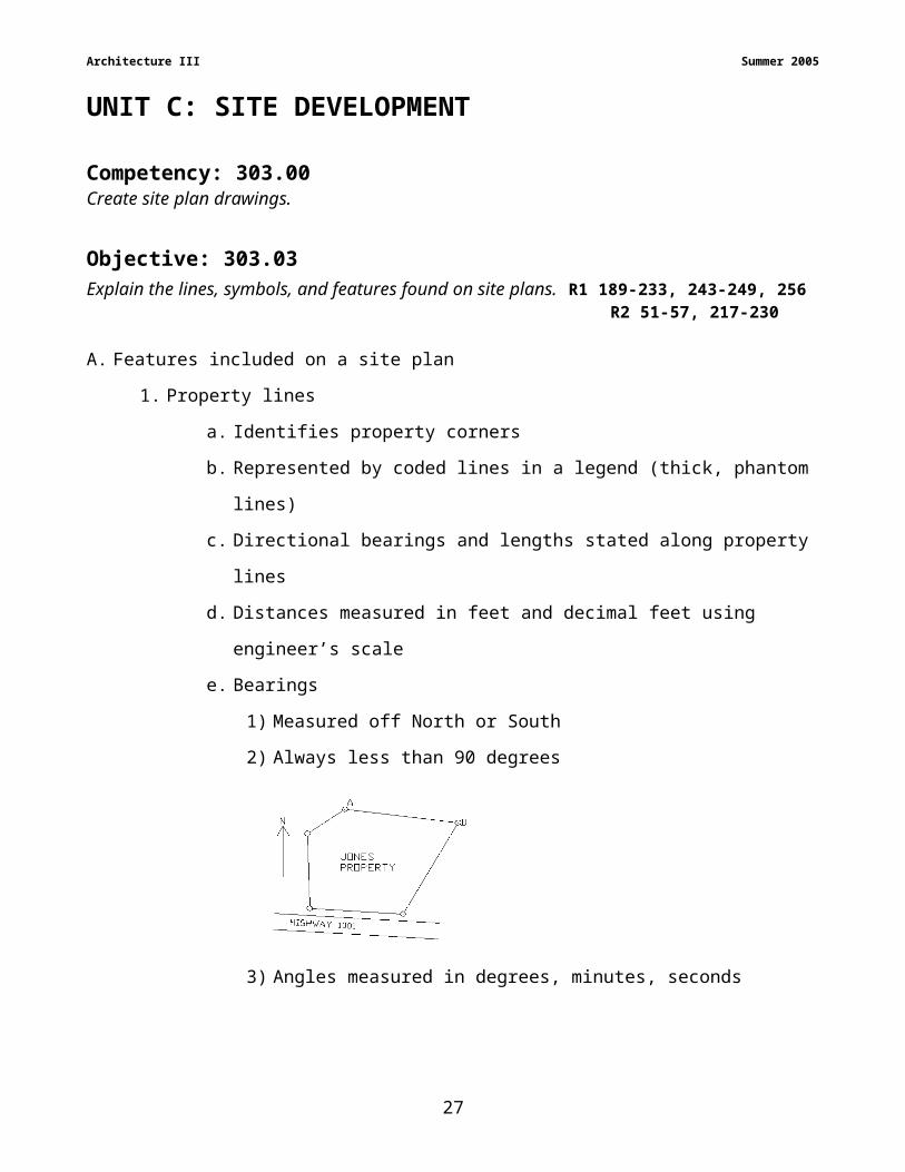
A. Features included on a site plan
1. Property lines
a. Identifies property corners
b. Represented by coded lines in a legend (thick, phantom lines)
c. Directional bearings and lengths stated along property lines
d. Distances measured in feet and decimal feet using engineer’s scale
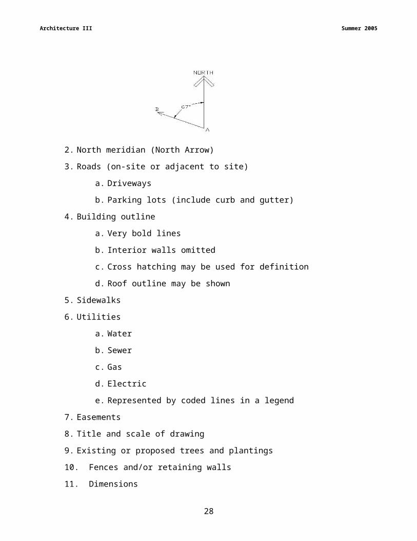
e. Bearings
1) Measured off North or South
2) Always less than 90 degrees
3) Angles measured in degrees, minutes, seconds
2. North meridian (North Arrow)
3. Roads (on-site or adjacent to site)
a. Driveways
23

Architecture III Summer 2005
b. Parking lots (include curb and gutter)
4. Building outline
a. Very bold lines
b. Interior walls omitted
c. Cross hatching may be used for definition
d. Roof outline may be shown
5. Sidewalks
6. Utilities
a. Water
b. Sewer
c. Gas
d. Electric
e. Represented by coded lines in a legend
7. Easements
8. Title and scale of drawing
9. Existing or proposed trees and plantings
10.Fences and/or retaining walls
11.Dimensions
a. Sizes, locations, and turning radii for roads, sidewalk, patios, and other
exterior features to constructed
b. Size and location of the building(s)
c. Annotation
1) Sizes, slopes, and materials used for drainage and utilites
2) Exterior feature materials and related construction information
d. Legends explain the meaning of special symbols
B. Topographical information
1. Topographic drawing describes the surface features of the building site
2. Contour information
a. Elevation
b. Benchmark
c. Contour lines
d. Contour intervals
24

Architecture III Summer 2005
e. Profile drawings
f. Spot elevations
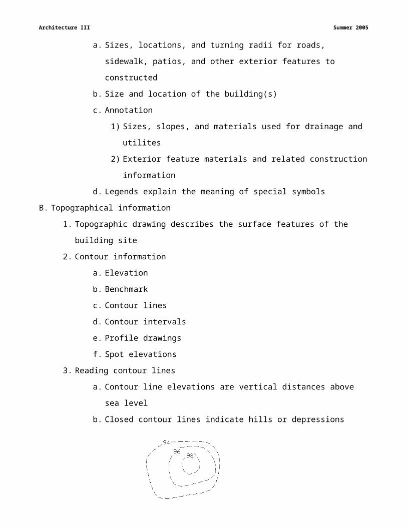
3. Reading contour lines
a. Contour line elevations are vertical distances above sea level
b. Closed contour lines indicate hills or depressions
c. “U” or “V” shaped contour lines that point toward higher elevations (uphill)
indicate ditches or streams
d. “U” or “V” shaped contour lines that point toward lower elevations
(downhill) indicates raised areas
e. Closely spaced contour lines indicate steeper slopes
f. Lines farther apart indicate flat areas
g. Evenly spaced contour lines indicate uniform slope
h. Contour lines that cross indicate same elevation
25
Architecture III Summer 2005
i. Profile drawings help interpret contour plans
Example #1
Example #2
4. Drawing contour lines
a. Short dashed lines indicate existing topography
b. Solid lines indicate proposed changes
c. Lines include numbers that indicate the elevation of the line
d. Every fifth line is drawn darker or bolder
e. Path or direction of a contour line is plotted by interpolating between
known elevations
26
Architecture III Summer 2005
C. Make measurements with the 1” = 10’, 20’, 30’, 40’, 50’, 60’, and 100’
1. Use Engineer’s scale
2. Engineer’s scale measures in feet and tenths of a foot.
27

Architecture III Summer 2005
UNIT C: SITE DEVELOPMENTCompetency: 303.00Create site plan drawings.
Objective: 303.04Explain how to develop a site plan drawing. R1-189-233, 243-249, 256
R2-51-57, 217-230
A. Develop the drawing
1. Choose a scale that allows for dimensions, titles, notes and a title block
2. Layout and draw property lines
3. Select a contour interval and draw existing contour lines
4. Locate and draw the center and edges of any existing streets and roads
5. Locate and draw proposed well and septic system (if required)
6. Locate and draw existing utilities and easements
7. Locate and draw existing trees and shrubs (if required)
8. Locate and draw the structures on the site
9. Locate and draw sidewalks, driveways, patios, or other site features
10.Redefine the topography
B. Site plan includes annotation and dimensions
1. Property line bearings and lengths (stated along the lines)
2. North arrow
3. Building is boldly and clearly outlined and labeled
i. Overall dimensions of the structure
ii. Structure located with respect to the property lines and significant features
4. Provide width and location dimensions
a. Note curb and gutter
b. Dimension turning radii
c. Note materials and symbols
5. Identify sidewalks, patios, and other features
a. Specify sizes and locations with respect to other features
b. Use materials symbols and specify with notes
6. Identify utilities
a. Lines are coded
28
Architecture III Summer 2005
b. Provide legend
c. Note sizes and types along lines
7. Tree and shrub types and sizes
8. Note benchmarks and contour line elevations
9. Drawing title and scale
10.Dimensioning
a. Sizes, locations, and turning radii
1) Roads, sidewalks, patios and exterior features
b. Size and location of buildings
c. Annotation
1) Sizes, slopes, and materials of drainage and utility features
2) Exterior feature materials and related construction information
3) Legends specify materials
29
Architecture III Summer 2005
UNIT C: SITE DEVELOPMENTCompetency: 303.00Create site plan drawings.
Objective: 303.05Draw a site plan for a single-level residential floor plan.
Requirements:
Each student is required to produce drawings of a site plan for the floor plan drawn in
Objective 203.08. This rubric is designed with the assumption the Site Plan contain a
residential structure specified by the instructor, drawn using board techniques or CAD
software and plotted to an appropriate scale.
1. Use board or CAD techniques
2. Use accepted drafting standards
3. Include title block.
4. Time Limit = 180 minutes
5. An effort should be made to create a balanced appearance within drawing space.
6. Your work should reflect an understanding of Topography, property lines, contour lines,
easements, utilities, location of structures, and site features.
Assessment: The problem will be evaluated based on the following criteria:
Site Development Concepts 30 pointsNotes and Dimensions 30 pointsAccuracy, Line Weight, Neatness 20 pointsCAD Drawing Technique 20 points
30
Architecture III Summer 2005
303.05 Draw a Site Plan for a single-level residential floor plan.
Each student is required to produce drawings of a site plan for the floor plan drawn in Objective 203.08. This rubric is designed with the assumption the Site Plan contain a residential structure specified by the instructor, drawn using board techniques or CAD software and plotted to an appropriate scale.
Criterion Statements Point Value
Rating
Site Development Concepts 30 Contour lines are reasonably interpolated using locations and elevations provided (natural contour
lines are drawn close to where they should be to evidence an understanding of interpolation) If required, the finished contour lines are drawn so as to provide a reasonable grading of the land Water is directed away from the structure A reasonable attempt at balancing the cut and fill is evident Solid contour lines represent the finished work Roads, driveways, sidewalks and parking as needed are provided The building outline is drawn Building is appropriately oriented on the site Sizes and offsets match floor plan provided Utilities are located Easements are shown Fences are shown Patios and decks are shown Turning radii are provided where needed Road, driveway, sidewalk, and parking sizes are practical and reasonable
Notes and Dimensions 30 Property line length and bearings are stated along the lines Building setbacks are provided with respect to property lines A legend is provided to explain line coding and symbols Overall building sizes are stated Utilities are identified Sizes of water and sewer lines are stated Sizes are given for roads, sidewalks, driveways, and parking lots A north arrow is drawn Street names and right-of-ways are given Bench marks are shown and described Contour line elevations are given A drawing title is provided A drawing scale is provided Dimensions and annotation are drawn with an appropriate size and style to make them clear and
easy to read Dimensions and annotation are on a separate layer
Accuracy, Line Weight, Neatness 20 Industry accepted standard symbols are used Symbol correctly sized and located Symbols exist on a dedicated layer Correctly oriented and positioned
CAD or Drawing Technique 20 Setup file for units, limits, grid, snap, and layers File correctly saved Layers correctly managed Line types correctly coded Drawings neatly laid out to balance space on the page Line connections connect when closely zoomed Lines are not over-drawn/ are continuous lines
Total 100
31
Architecture III Summer 2005
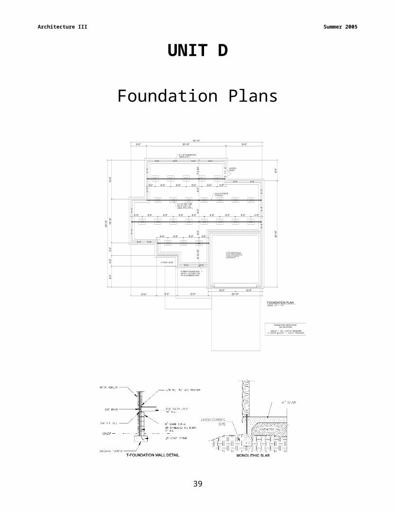
UNIT D
Foundation Plans
32
Architecture III Summer 2005
UNIT D: FOUNDATION DESIGN AND CONSTRUCTIONCompetency: 304.00Design and draw foundation plans.
Objective: 304.01Identify terms and definitions relating to foundation design and construction.
R1 pgs. 626-693
1. Soil Bearing Capacity – A design value specifying the amount of weight a square foot
of soil can support
2. FHA Formula – A formula based upon the thickness of the foundation wall used to
design proper footing size
3. Tensile Load – The resistance of the load to the tendency to stretch
4. Longitudinal Rebar – Steel Support bars placed along the bottom portion of the
footing used to carry tensile loads
5. Transverse Rebar – Steel support bars tied to longitudinal bars at regular intervals
used to prevent cracking
6. Chairs – Supports used to hold rebar in place before concrete is poured
7. Lintel – Horizontal structural member over an opening in a masonry wall
8. Girder – A beam used to support the floor joists as they span across the foundation
9. Span – The horizontal distance between two supporting members
10. Deflection – The amount of bending that occurs when a structural member is loaded
11. Piles – A vertical foundation support driven into the ground used to provide support in
areas of loose soil
12. Expansion Joints – Joints placed in concrete construction to reduce cracking due to
expansion and contraction
13. Pilaster – A post built into a wall used to reinforce a high foundation wall
33
Architecture III Summer 2005
UNIT D: FOUNDATION DESIGN AND CONSTRUCTION
Competency: 304.00Design and draw foundation plans.
Objective: 304.02Explain use of footings, foundation walls, girders, piers, ventilation, and slab floor/foundations.
R1 pgs. 626-693A. Continuous wall footings
1. Footing size is determined
a. Engineering data regarding the soil and structural loads
b. NC Building Code minimum footing widths
1. Single story, conventional wood frame = 16”
2. Single story, brick veneer over wood frame = 16”
3. Use Minimum Width of Concrete or Masonry Footings chart for
various conditions
4. Assumes a soil with a bearing capacity of 2000 psf
c. Accepted “rule of thumb” is based on thickness of foundation wall
1. Width of footing = 2 x foundation wall thickness
2. Depth of footing = foundation wall thickness
3. Assumes firm, undisturbed soil or engineered fill
4. Minimum soil bearing capacity of 2000 psf
2. Steel reinforcement may be added to footing to control tension forces
a. Two longitudinal rebars, in bottom portion of footing carry tensile loads
1. Prevents spreading apart of footing where cracks occur due to
uneven settlement
2. Tension forces occur only in bottom portion of footing
3. Top portion of footing is in compression
b. Bar size is based on 1/8”
Example: #4 bar = 4/8” (1/2)
c. Transverse bars may be tied to longitudinal bars at regular intervals to aid
in resisting cracking
d. “Chairs” hold bars in place
34

Architecture III Summer 2005
3. Footing thickness to width ratios require increases in footing widths, turn, and
increase in thickness
4. Stepped footings
a. Shaped with vertical and horizontal parts resembling “steps”
b. Vertical step not more than ¾ the distance of horizontal depth
c. Used on hilly terrain to reduce excavation and materials costs
d. Constructed with 8” module when concrete block is used for foundation wall
B. Foundation walls
1. Concrete and masonry wall thickness determined from NC Residential Building
Code
a. Unbalanced fill
1. Height of earth pushing against the foundation wall
2. Wet soil produces greater pressure than dry soil
b. Type of wall construction (hollow, solid, grouted, etc.)
2. Lateral resistance to earth pressures provided by intersecting walls, floors, and
pilasters
3. Pilasters are posts built into a wall.
a. Used as supports for beam endings and resistance to pressure
b. Masonry units are interlocking with units in an alternating direction.
c. May be filled with grout and/or steel rebars
4. Poured concrete walls can be reinforced with steel rebars placed in tension zone
5. Poured concrete walls can be tied to poured concrete footings using “keys” formed
into footing
6. Foundation walls must be located in the center 1/3 of the footing.
7. Extends a minimum of 8” above grade when using wood construction
8. Minimum distance from floor to ceiling in a basement = 7’-0”
9. Lintels are structural members over openings in masonry walls
a. 4” minimum bearing
b. Steel or masonry
10.Foundation walls require damp proofing on outside wall
a. Heavy coats of tar or two coats of cement based paint for basement walls
b. Thin coats of cement-mortar materials or parging
35

Architecture III Summer 2005
c. Drain tile
1. 4” perforated pipe surrounds structure at bottom of wall
2. Set in washed gravel from wall
3. Covered with 6” of washed gravel above
a. Holds back soil
b. Allows water to enter pipe
4. Water collected in pipe is carried away
d. Polyethylene or plastic sheeting
1. Thickness of material measured in “mils.”
2. 6 mil is common sheeting thickness.
C. Girders
1. Design
a. Based on material, span, and load
b. Loads include live and dead
c. Determine load area(s) to be supported by beam and multiply by the
sum of live and dead loads
d. Determine loads imposed by walls and significant features and add to
area loads
e. Divide total load by the length of beam to determine load per foot
f. Most charts require load per foot of beam to calculate beam size and
span
g. Loads often expressed in “kips.” (1 kip = 1000 lb)
h. When beam size is not sufficient to carry the load
1. Shorten span by increasing number of piers or columns
2. Change material
3. Pier spacing is equal
4. Change species and/or grades of wood
i. Beam charts often limit size based on deflection
1. Deflection is amount of bending that occurs when a structural
member is loaded
2. Usually limited to 1/360 of the span
36

Architecture III Summer 2005
2. NC Residential Building Code charts for built-up wooden girders include pier and
footing sizes.
a. Determine area supported by pier
b. Use appropriate chart for single or multi-level structures
c. Determine depth of the structure
d. Determine whether an interior or exterior girder
e. Select grade and species of lumber
f. Read size of pier and pier footing from chart
1. Masonry pier height is limited by size of pier and type of construction
2. Interior and exterior piers treated differently
3. Piers capped
a. 4” of solid masonry for a single-story structure
b. 8” for a two-story building
D. Piles
1. Driven into soil or onto bedrock without a separate footing
2. Used to support very heavy structures or structures built on poor soils
3. Often used when footings cannot be stabilized in loose soil
Example: beach houses built on loose sand
4. Materials
a. Treated Wood
b. Steel pipes filled with concrete
c. Steel beams
d. Bored holes filled with reinforced poured concrete
e. Pre-cast concrete
E. Foundation Ventilation
1. NC Building Code minimum requirement is 1 sq. ft. ventilation for every 150 sq. ft.
of crawl space area.
2. Vapor barriers reduce ventilation requirements.
F. Slab Foundation
1. Reinforced concrete floor and footing
2. Poured at the same time (monolithic)
3. Footings may be poured separately from floor
37
Architecture III Summer 2005
4. Requires less time and labor than T-foundation
5. Turned down extension extends below frost line
6. Perimeter insulation required where heat is lost around edges of the slab
7. NC Residential Building Code requirements for slab construction
a. Vegetation, top soil, and foreign material is removed
b. Below grade 4” slab poured on clean, graded sand, gravel, or crushed
stone
c. Vapor barrier is placed between slab and sub-grade
1. Where no base course is used
2. Unless slab is used in unheated situation
8. Minimum slab thickness for residential floor construction = 4”
9. Concrete Construction
a. Composed of cement, sand, stone or gravel aggregate, and water
b. Varying amounts of ingredients will change strength and properties
c. Cement composed of lime, silica, and other materials
d. Cures over a very long time
1. Temperature effects strength and harms exposed surface
2. Extreme cold weather slows curing process and can cause water
within mix to freeze
3. Extreme hot weather causes water to evaporate or elevates mixture
e. Temperature and moisture conditions are controlled during curing
f. Purchased by cubic yard (3’ x 3’ x 3’ = 27 cu. ft)
g. Strength measured in PSI (pounds per square inch)
h. Cracking
1. Expansion and contraction due to temperature changes
2. Moisture content
3. Large areas more likely to crack than smaller areas
4. Joints may be cut into freshly placed concrete with a joining tool or
cut into cured concrete with a masonry saw.
5. Floor slabs are not bonded to columns or walls.
6. Expansion joints are positioned next to walls.
7. Building felt or fiberboard commonly used as expansion joints
38
Architecture III Summer 2005
8. Fiberglass fibers may be used in mix rather than steel
9. Wire mesh used to reinforce slabs and control cracking
10.Pre-manufactured control joints placed in the slab to control cracking
10.Pressure treated lumber and plywood necessary where members come in contact
with concrete
39
Architecture III Summer 2005
UNIT D: FOUNDATION DESIGN AND CONSTRUCTIONCompetency: 304.00Design and draw foundation plans.
Objective: 304.03Design and draw a foundation system
Requirements:
Each student is required to produce drawings of a foundation for the floor plan drawn in
Objective 203.08. This rubric is designed with the assumption the Foundation Plan be for a
residential structure specified by the instructor, drawn using board techniques or CAD
software and plotted to an appropriate scale.
1. Use accepted drafting standards
2. Include title block.
3. Time Limit: 180 minutes
4. An effort should be made to create a balanced appearance within drawing space.
5. Your work should reflect an understanding of Topography, property lines, contour lines,
easements, utilities, location of structures, and site features.
Assessment: The drawing will be evaluated based on the following criteria:
Design Concepts 25 pointsFoundation Symbols 25 pointsArchitectural Dimensioning 25 pointsCAD Drawing Technique 25 points
40

Architecture III Summer 2005
UNIT D: Foundation Design and Construction
Competency: 304.00Design foundation plans
Objective: 304.03Design and draw a foundation system.
This rubric is designed with the assumption that the foundation drawing will be for either a slab or crawlspace as specified by instructor.
Design Concepts0-25 points Rating
• Design demonstrates placement consideration of footing, foundation wall, load bearing wall support, live/dead loads, soil, openings. Basic fundamentals of the foundation plan are correct.
Foundation Symbols0-25 points Rating
• Industry accepted standard symbols are used.• Symbols correctly sized and located.• Correctly oriented and positioned.
Architectural Dimensioning0-25 points Rating
• Dimensional styles are appropriate• Annotations are appropriate style and size• Hard copy is printed to scale.• All required dimensions are clear and visible.• Dimensions are balanced and easily read.
CAD Drawing Technique0-25 points Rating
• Drawing setup. Dimensioning and text size, units, etc.• File correctly saved.• Line weights and colors managed correctly• Drawings neatly laid out to balance space on the page.• No stray lines or improper marks.
Total Points: ____________________
41

Architecture III Summer 2005
UNIT E
Stair Design and Construction
42

Architecture III Summer 2005
UNIT E: STAIR DESIGN AND CONSTRUCTION
Competency: D305.00Design and draw stair systems.
Objective: D305.01Identify terms and definitions relating to stair design and construction. R1 pgs. 626-693
Terms and definitions
1. Balusters – Vertical members that support the handrail on open stairs
2. Circular Stairs – Stairs that have trapezoidal steps that rise along an irregular curve or arc
3. Double-L Stairs – Stairs that have two 90° turns and two landings along the flight, but are not U shaped
4. Enclosed stairs – Stairs that have a wall on both sides; also known as closed, housed, or box stairs
5. Guardrail – A horizontal protective railing used around stairwells, balconies, and changes of floor elevation greater than 30 degrees. This is formed by the vertical baluster beneath the handrail.
6. Handrail – This items helps people steady themselves as they traverse areas like stairs and ramps where a person might slip, trip, or fall. Railing used to slide your hand along as you walk down stairs.
7. Headroom – The vertical distance measured from the tread nosing to the ceiling above the stairs. Building codes will specify a minimum distance.
8. Housed stringer- A stringer that has been routed or grooved to receive the treads and risers
9. Kick Block or Kicker – Used to keep the bottom of the stringer from sliding on the floor when downward pressure is applied to the stringer
10.L Shaped Stairs - A set of stairs that have one landing and turn at some point along the flight of stairs
11.Landing – The floor area at either end of the stairs usually occurs at a direction change or elevation change in the stairs
12.Newel – The main post of the handrail at the top, bottom, and points where the stairs change direction
43
Architecture III Summer 2005
13.Nosing – The rounded projection of the tread that extends past the face of the riser
14.Open stairs – Stairs that have no wall on one or both sides
15.Rise – The vertical distance from top of one tread to the same position on the next tread
16.Riser – The vertical face of the step
17.Run – The horizontal distance from the face of one riser to the face of the next
18.Spiral Stairs – are steps that rise in a circle about a center. Used where space is limited
19.Stairwell opening – The opening on the next floor that allows access by the stairs.
20.Straight Run Stairs – Steps that rise in a circle about the center point. These stairs can be used where little space is available.
21.Stringer or Stair Jack – The inclined support member of a stair that supports the risers and treads. A notched stringer is used for enclosed stairs.
22.Total Rise – The total floor-to-floor height of the stairs
23.Total Run – The total horizontal length of the stairs
24.Tread – The horizontal member of each step on which a person steps
25.U Stair – Two flights of steps parallel to each other with a landing between
26.Winder Stairs – Pie-shaped steps that are substituted for a landing. This type of stair is used when space is limited.
44
Architecture III Summer 2005
UNIT E: STAIR DESIGN AND CONSTRUCTION
Competency: D305.00Design and draw stair systems.
Objective: 305.02 R1 pgs. 739-750 & R2 pgs. 353-368Identify the parts and standards used to construct a stair system.
A. Stair Elements
1. Headroom
2. Nosing
3. Rise
4. Riser
5. Run
6. Total rise
7. Total run
8. Tread
9. Stairwell opening
B. Supporting structure
1. Housed stringer
2. Plain stringer
3. Landing
C. Railing members
1. Guardrail
2. Handrail
3. Balusters
4. Newel
D. Stair types
1. Straight run stairs
a. Most commonly used
b. No turns
c. Require long open space
45
Architecture III Summer 2005
2. L stairs
a. One landing with a turn
b. Used when little space is available
3. Double-L stairs
a. Two 90 degree turns, and two landings
b. Not U shaped
c. Often used in residential construction
46
Architecture III Summer 2005
4. U stairs
a. Two flights of parallel stairs
b. Introduces a landing midway the run
c. May be open or closed
d. Types
1. Narrow U
2. Wide U
5. Winder stairs
a. Used in place of a landing
b. Pie-shaped (triangular) steps
c. Mid-point width should be equal to regular tread width.
d. Not very safe
6. Spiral Stairs
a. Rise in a circle about a point
b. Decorative styles can be used
c. Used where little space is available
47
Architecture III Summer 2005
7. Circular stairs
a. Trapezoid steps (tread)
b. Irregular curve or arc is primary shape
c. Custom made
d. Requires much space
e. Expensive to build
E. General Information
1. Main stairs
a. Extend between main floors
b. Assembled from high quality, prefabricated parts
c. Provides elegant focal point for two-story homes
2. Service stairs
a. For frequent or heavy use
b. May extend to basement or attic
48

Architecture III Summer 2005
UNIT E: STAIR DESIGN AND CONSTRUCTION
Competency: D305.00Design and draw stair system.
Objective: 305.03 Explain the calculations for rise, run, total rise, total run, and floor cutout.
R1 pgs. 739-750 & R2 pgs. 353-368A. Essential building considerations
1. Minimum headroom = 6’-8”
2. Riser height = 7” to 7 5/8”
3. Riser material thickness = ¾”
4. Tread depth = 10” to 11½”
5. Tread depth material thickness = 1¼”
6. Tread width = 36” clear above or below handrail(s)
7. Handrail heights = 30” to 38”
8. Guardrail heights
a. Required if landing is 30” above floor or grade
b. Minimum height = 36”
c. Vertical members spacing maximum of 4”
d. Do not allow passage of a 6” diameter sphere
9. Require at least one handrail where four or more risers are present
a. At least 1½” between handrail and wall
b. Handgrip may not exceed 2 5/8” in cross-section
10.Check local codes for winders, spiral stairs, illumination, etc.
11.Nosing projects 1 1/8” to 1 ½”
B. General Design Rules
1. Slope of stairs (rise and run ratio) should be between 30 and 35 degrees.
2. Sum of two risers and one tread should equal 25”
3. Riser height multiplied by tread width equals approximately 75”.
4. Sum of one riser and one tread equals approximately 17” to 18.”
C. Stair Calculation
1. Determine total rise of stairs
a. Distance from finished lower floor to finished ceiling
49

Architecture III Summer 2005
b. Thickness of ceiling material
c. Width of floor joist
d. Thickness of subfloor
e. Thickness of finished floor
Example:
Finished lower floor to finished ceiling 8’-0”
Thickness of ceiling material
(Gypsum board or drywall)
½”
Width of the floor joist
(2”x8” joist)
7 ¼”
Thickness of the subfloor
(1/2” plywood sheathing)
½”
Thickness of the finished floor
(floor and underlayment)
1”
TOTAL RISE = 8’ – 10¼”
2. Determine the number of risers needed
a. Convert TOTAL RISE to inches
b. Divide TOTAL RISE by 7
Example:
TOTAL RISE / 12
106.25” / 7 = 15.17 risers
Number of risers needed is 15 or 16
3. Determine height of riser
a. TOTAL RISE inches
b. Divide by number of risers
Example:
TOTAL RISE inches / 15 risers = 7.08”
c. Each riser must be equal same height
50
Architecture III Summer 2005
4. Check Rules indicated earlier in Section B
a. Ensure accuracy of riser and tread
b. Always one less tread than risers
5. Determine total run
a. Multiply tread width (10”) by number of treads (14)
Example:
Tread width x treads = TOTAL RUN
10” x 14 = 140”
6. Determine floor cutout size (upper floor)
a. Lay out scaled drawing including calculated rises and run information
b. Draw a line, along the stair nosing, from bottom tread to top tread
c. Measure a vertical line to represent headroom
d. Draw a line parallel to line from bottom tread to top tread (step b.)
e. Measure resulting stairwell rough opening
51
Architecture III Summer 2005
UNIT E: Stair Design and Construction
Competency: 305.00Design and draw a stair system.
Objective: 305.04Draw plans for stair construction. R1 pgs. 739-750
RequirementsEach student is required to produce drawings of a stair plan for a residential structure. This
rubric is designed with the assumption that the stair design should include the necessary
drawings, dimensions, and notes for total rise, total run, treads, riser type, thickness,
stringers, and railing specifications for a typical stair system drawn using board techniques
or CAD software and plotted to an appropriate scale.
1. Use accepted drafting standards
2. Include the title block
3. Time Limit: 180 minutes
4. An effort should be made to create a balanced appearance within drawing space.
5. Work should reflect an understanding of the construction of total rise, total run, treads,
riser type, thickness, stringers, and railing specifications for a typical stair system and
understand the notes for a stair design.
Assessment: The problem will be evaluated based on the following criteria
Design Concepts 30 pointsArchitectural Notes and dimensioning 30 pointsAccuracy, Line Weight, Neatness 20 pointsCAD Drawing Technique 20 points
52

Architecture III Summer 2005
305.04 Draw plans for stair construction. Each student is required to produce drawings of a stair plan for a residential structure. This rubric is designed with the assumption that the stair design should include the necessary drawings, dimensions, and notes for total rise, total run, treads, riser type, thickness, stringers, and railing specifications for a typical stair system drawn.Criterion Statements Point
Value RatingDesign Concepts 30
Finish flooring Treads, Risers Nosing Stringers Handrails Guardrails Balusters Newels Material symbol(s) Floor structural elements illustrated and annotated Identify floor levels (sub floor or finished floor) Closet details under stairs Landing construction details
Architectural Notes and Dimensioning 30 All materials labeled Correct size of materials Ceiling height Annotation should include the material sizes and quality Rise for each step Number of risers Total rise Run for each step Number of run (tread) Total run Nosing Headroom Handrail/guardrail heights Dimensions should not be crowded. Follows appropriate dimension standards. Title and scale
Line Weight, Neatness 20 Line weight is neat, clean, and meets acceptable drafting standards for thickness
and darkness. Industry accepted standard symbols are used
CAD Drawing Technique 20 Setup file for units, limits, grid, snap and layers File correctly saved Layers correctly managed Line types correctly coded Drawings neatly laid out to balance space on the page Line connections connect when closely zoomed Lines are not over-drawn and are continuous lines
Total 100
53
Architecture III Summer 2005
UNIT F
Advanced Kitchen and Bath Design
54
Architecture III Summer 2005
UNIT F: ADVANCED KITCHEN AND BATH
Competency: 306.00Design and draw interior elevations for kitchens and baths.
Objective: 306.01Identify terms and concepts related to kitchen and bath design. R1, pgs. 250-255
R1, pgs. 478-495
Terms and definitions1. Base cabinet – Cabinets in a kitchen or bathroom which sit on the floor
2. Baseboard – The finish trim where the wall and floor intersect, or an electric heater
that extends along the floor
3. Bullnose – Rounded edges of cabinet trim
4. Cabinet work – The interior finish woodwork of a structure, especially cabinetry
5. Chair rail – Molding placed horizontally on the wall at the height where chair backs
would otherwise damage the wall
6. Ergonomics – The study of human space and movement needs as they relate to a
given work area, such as a kitchen
7. Fabrication – Work done on a structure away from the job site
8. Lavatory – A bathroom sink, or a room which is equipped with a washbasin
9. Millwork – Finished woodwork that has been manufactured in a milling plant
10.Modular cabinet – Prefabricated cabinets that are constructed in specific sizes called
modules
11.Molding – Decorative strips, usually made of wood, used to conceal the seam in other
finishing materials
12.Prefabricated – Buildings or components that are built away from the job site and
transported ready to be used
13.Section – A type of drawing showing an object as if it had been cut through to show
interior construction
14.Specifications – An exact statement describing the characteristics of a particular
aspect of the project
55

Architecture III Summer 2005
UNIT F: ADVANCED KITCHEN AND BATH
Competency: 306.00Design and draw interior elevations for kitchens and baths.
Objective: 306.02Explain the elements of kitchen and bath design. R1, pgs. 250-255
R1, pgs. 478-495
A. Kitchen & Bath Elevations and Layout
1. Purpose of kitchen elevations
a. Show the exterior of cabinets, plumbing fixtures, and appliances
b. Give general dimensions, notes, and specifications
2. Cabinet elevations are developed from floor-plan drawings.
a. Floor plan drawings establish cabinet elevation lengths
b. Dimensions are projected directly from floor plan
3. Cabinet elevations may be as detailed as desired by designer or architect
a. Standard scale for cabinet elevations is ¼”= 1’
b. May show very clear and well drawn without detail or artwork not specific to
construction
c. May be drawn artistically
4. Key cabinet elevations to floor plans
a. May be keyed with room titles
b. May use an arrow with a letter inside that corresponds to a symbol on floor plan
c. Symbol used to correlate detail drawings with location on elevation
5. Cabinet, fixture, and appliance elevations are drawn from a standing view.
a. Line of sight is noted on floor plan drawing using a cutting plane line.
b. Elevations are two-dimensional.
c. Height and length are shown in external view.
d. Depth is shown at cutting plane line.
e. Multiple elevations are drawn on one sheet to describe front elevation of each set
of cabinets and appliances.
6. Dimensions are included on elevation views.
a. Include horizontal dimensions
i. Drawer stacks
56
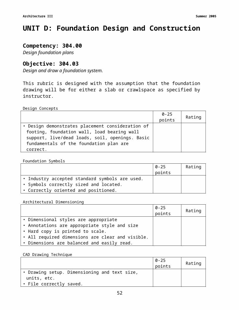
Architecture III Summer 2005
ii. Door units
iii. Openings
b. Overall horizontal dimensions are included for each elevation view.
c. Include vertical dimensions
i. Counter height
ii. Distance between countertop and bottom of upper cabinet
iii. Upper cabinet height
d. Overall vertical dimensions are included for each elevation view.
B. Kitchen Design Considerations
1. Cabinets can be designed for ease of access or adjustable for future needs.
2. Standard cabinet dimensions
a. Base cabinet height = 32”; depth = 24”
b. Base cabinet may be as high as 42” (for very tall people)
c. Counter depth = 25”
d. 4” toe kick space is required on base cabinets
e. Upper cabinet depth = 12”
f. Upper cabinet height = 30”; over sink height = 18”-24”
g. Distance between counter and upper cabinet = 18”-30”
h. Eating bar base cabinet = 36” high with 12”-15” overhang
i. Drop eating bar = 30” high with a 12” overhang
3. Considerations should be made for space to open drawers and cabinet doors.
4. Range, sink, and workspace next to refrigerator should be on the same level
5. May require at least one counter at a height of 32” for wheelchair access
a. Provide a 27” recessed space below counter
b. Provide a larger than normal toe space
C. Bath Design Considerations
1. Kitchen cabinet design features can be considered for baths
a. Toe kick space
b. Drawer and door swing space
c. Wall mount sink may be provided but does not allow for counter space and
storage
2. Vanity cabinet height = 28”-32”
57

Architecture III Summer 2005
3. Vanity can be designed with recessed space for sitting or wheelchair access
4. Grab bars are placed to assist movement for handicapped users
5. Benches can be designed in locations where sitting or transferring from wheelchair is
necessary
58

Architecture III Summer 2005
UNIT F: ADVANCED KITCHEN AND BATH
Competency: 306.00Design and draw interior elevations for kitchens and baths.
Objective: 306.03Describe plans for kitchen cabinet drawings. R1, pgs. 250-255
R1, pgs. 478-495
A. Kitchen cabinet plans consist of large-scale
1. Floor plan
2. Typical section drawing
3. Elevations
B. Large scale, Kitchen Floor Plan layouts based on manufactured cabinet sizes
1. Greater detail than on Normal Floor Plan
2. Shows interior elevation identifiers
3. Shows page references for large-scale details
4. Cabinets designed to fit into available floor space using modular cabinet components and dimensions
C. Detail (Sectional) drawings explain cabinet construction
1. Drawing elements
a. Floor line
b. Ceiling line
c. Soffit/Fascia layout, if used
d. Locations of electrical/mechanical systems directly related to cabinetry
e. Counter tops
f. Shelves
g. Back splash
h. Toe space (clearance)
i. Cabinet construction elements
2. Drawing dimensions and annotations
59
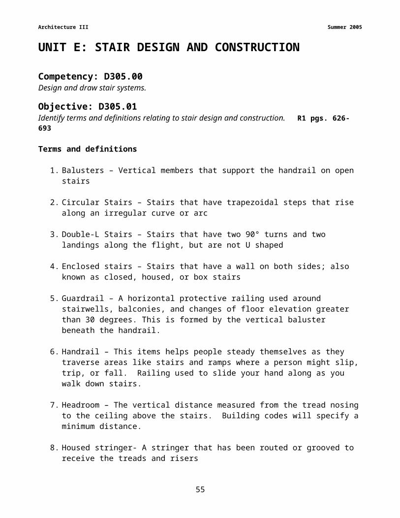
Architecture III Summer 2005
a. Base cabinet heights
b. Wall cabinet heights
c. Distance between countertop and wall cabinets
d. Back splash height
e. Counter top thickness
f. Overall floor to ceiling heights
g. Wall and base cabinet depths
h. Soffit/fascia depth
i. Toe space depth and height
D. Interior Elevation drawings illustrate cabinet layout and construction
1. Drawing elements
a. Sectional drawing of adjacent cabinets
b. Front view of base and upper cabinets
c. Front view of appliances
d. Soffit/Fascia
e. Walls
f. Floor and ceiling lines
g. Optional
1) Hardware
2) Dotted lines indicating interior shelves
3) Visible window and door features
4) Related electrical and mechanical systems
2. Dimensions and annotations
a. Base unit widths
b. Wall units widths
c. Overall width of cabinets
60

Architecture III Summer 2005
d. Overall width of room
e. Vertical distances
f. Materials and finishes
1) Walls
2) Ceilings
3) Counter tops
4) Back splashes
5) Cabinets
E. Drawings are identified with descriptive titles and drawing scale
61

Architecture III Summer 2005
UNIT F: ADVANCED KITCHEN AND BATHCompetency: 306.00Design and draw interior elevations for kitchens and baths.
Objective: 306.04Draw interior elevation plans for kitchens and baths.
RequirementsEach student is required to produce drawings of a stair plan for a residential structure. This
rubric is designed with the assumption that the stair design should include the necessary
drawings, dimensions, and notes for total rise, total run, treads, riser type, thickness,
stringers, and railing specifications for a typical stair system drawn using board techniques
or CAD software and plotted to an appropriate scale.
1. Use accepted drafting standards
2. Include title block
3. Time limit: 180 minutes
4. Create a balanced appearance within drawing space
5. Work should reflect an understanding of kitchen and bath cabinetry, symbols, and
dimensioning
Assessment: The problem will be evaluated based on the following criteria:
Design Concepts 25 pointsCabinet, Plumbing, and Appliance symbols 25 pointsDimensions and Annotations 25 pointsDrawing Technique 25 points
62

Architecture III Summer 2005
306.04 Draw interior elevation plans for kitchens and baths. Each student is required to produce interior elevation plans for a kitchen and bath in a residential structure. This rubric is designed with the assumption that the plan should include the necessary drawings, dimensions, and notes drawn using board techniques or CAD software and plotted to an appropriate scale.Criterion Statements Point
Value RatingDesign Concepts 25
Cabinet sizes and styles available in cabinet manufacturer’s literature Overall measurements coincide with individual cabinet modular measurements Design reflects understanding of available cabinet units Layout reflects accepted standards for kitchen design
Cabinet, Plumbing, and Appliance Symbols 25 Includes plan view with identifying elevation indicators Elevations include section views of intersecting cabinets Includes cabinet details
o Backsplasho Toe spaceo Counter topo Shelveso Rails and stileso Floor and ceiling lines
Soffit/fascia details (if used) Drawings agree with stated dimensions Cabinet sizes agree with industry standards Adjacent walls are shown Visible windows and doors are shown Handles/knobs locations are shown Appliances and plumbing fixtures are shown
Dimensions and Annotation 25 Annotation and dimensional figures are easily readable Drawn to industry standards Provides descriptive titles and drawing scale Identifiers correctly oriented Elevation identifiers agree with floor plan Required dimensions provided
o Widths of individual base and wall unitso Overall widthso Vertical distances for base and wall unitso Vertical distances between base and wall unitso Backsplash heighto Counter top thicknesso Overall floor to ceiling heighto Depths of base and wall unitso Depth and height of toe space
CAD Drawing Technique 25 Setup file for units, limits, grid, snap and layers File correctly saved Layers correctly managed Line types correctly coded Drawings neatly laid out to balance space on the page Line connections connect when closely zoomed Lines are not over-drawn and are continuous lines
Total 100
63
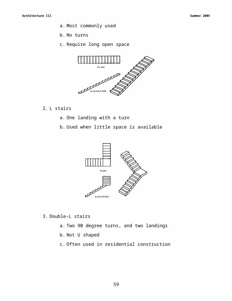
APPENDIX A
Bibliography / References
Textbooks
R1 Jefferis, Alan & David A. Madsen. (2004). Architectural Drafting and Design. Albany, NY: Delmar Thomson Learning.
R2 Kicklighter, Clois E. & Joan C. Kicklighter. (2004). Architecture Residential Drafting and Design. Tinley Park, IL: The Goodheart-Wilcox Company, Inc..
CAD Software Websites
AutoCADLT, AutoCAD– www.autodesk.com
Softplan - http://www.softplan.com
Student Version Pricing for CAD Software – www.journeyed.com
64
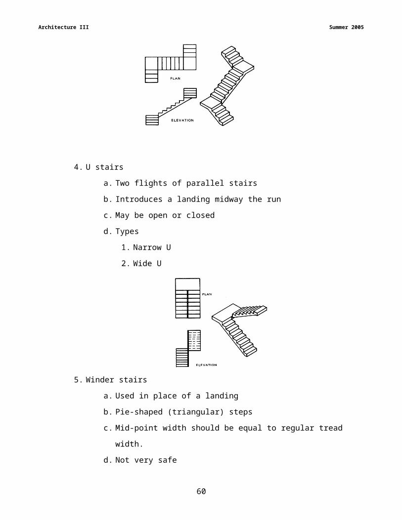
APPENDIX B
Vendor’s – Texts – Software – Literature
65
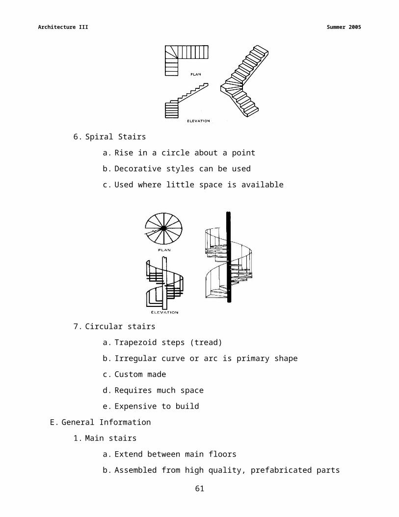
Vendor’s – Texts
Amazon.com, Inc. (Book resource)www.amazon.com
Glencoe/McGraw-HillPam Angotti6510 Jimmy Carter BoulevardNorcross, GA 30071Phone: 919-469-4517Fax: [email protected]
Goodheart-Willcox PublishingLiz Myhre18604 West Creek DriveTinley Park, IL 60477Phone: 800-365-3907Fax: [email protected]
Delmar Thomson LearningPatrick Delaney7813 Waterford Ridge Dr. #702Charlotte, NC 28212Phone: [email protected]
NC-DPI
Tom ShownDepartment of Public InstructionInstruction Technology & Human Services6360 Mail Service CenterRaleigh, NC 27699-6360Phone: 919-807-3880Fax: [email protected]
NC SkillsUSA VICA
Glen BarefootDepartment of Public InstructionInstruction Technology & Human Services6360 Mail Service CenterRaleigh, NC 27699-6360Phone: 919-807-3887Fax: [email protected]
National SkillsUSA VICAP.O. Box 3000Leesburg, VA 20177-0300Phone: 703-777-8810Fax: 703-777-8999www.vica.org
Software
Autodesk Products (ie AutoCAD 2006)Kris DellADADemic/Applied Software3200 Northline Ave, Suite 130Greensboro, NC 27403Phone: 704-491-2285Fax: [email protected]
1

APPENDIX CTrade and Industrial Education - Drafting Facility Equipment List
Courses taught within the facility: Drafting I DFT Code: 7921Drafting-Engineering II ENG Code: 7972Drafting-Engineering III Code: 7973Drafting-Architecture II ARC Code: 7962Drafting-Architecture III Code: 7963
Equipment DFT ENG ARC2D CAD Software (AutoCAD, AutoCAD LT) 1S 1S 1S3D CAD Software (Rhino 3D, Solidworks) 1S 1S 1SC or D size plotter/printer 1F 1F 1FDrafting stool 1S 1S 1SDrafting table/computer table 1S 1S 1SInstructor chair 1F 1F 1FInstructor desk 1F 1F 1FPC to TV converter or LCD panel screen for projector 1F 1F 1FPentium III (or better) computer w/ 10 GB hard drive or higher, 450 MHz (or better) suggested clock speed, 128 MB RAM, 52X CD-ROM, 3.5 floppy drive, 17” (or larger) monitor, Open GL graphics card w/ 32 MB or better VRAM & input/output, multimedia capability, NIC
1S 1S 1S
Printer 1F 1F 1FTV/VCR 1F 1F 1F
Tools and Other Items Under $100Equipment DFT ENG ARC
Ames Lettering Guide 1S 1S 1SBrush, dusting 1S 1S 1SCalculator 1FCompass 1S 1S 1SCompass Lead, tube (gross) 1FCover, drawing board 1S 1S 1SErasing Shield 1S 1S 1SFrench Curve 1S 1S 1SGauge, screw pitch 1:4SGauge, small hole 2FGauge, vernier height 10” 2FLead Holder 2FLead refills, 2H & 6H 1S 1S 1SPaper cutter 1F 1F 1FParallel bar 1S 1S 1SPrinter table 1F 1F 1FProtractor, plastic 1S 1S 1SScale, triangular, architect’s 12” 1S 1S 1SScale, triangular, engineer’s 12” 1S 1S 1SScale, triangular, mechanical 12” 1S 1S 1SScale, triangular, metric 12” 1S 1S 1STemplate, bolts & nuts 10FTemplate, circles, fraction 1S 1S 1STemplate, circles, metric 1S 1S 1STemplate, electrical 10FTemplate, ellipses 1S 1S 1STemplate, house plan & plumbing 1S 1S 1STemplate, large isometric 10FTemplate, machine & cap screws 10FTemplate, screw threads 10FTemplate, small isometric 1S 1S 1STriangle, adjustable 1:4S 1:4S 1:4STriangle, 30° x 60° 10” 1S 1S 1STriangle, 45° 10” 1S 1S 1S
Quantities are listed per: F=Facility C=Center S=Student
66

APPENDIX DFacility Design Specifications
Program Area: Trade & Industrial Education
Course Title: Drafting - Architectural III
Course Description:
Purpose:
This course is focused on the principles, concepts, and use of complex graphic tools used in the field of architecture, structural systems, and construction trades. Emphasis is placed on the use of CAD tools in the identification of architectural styles, and production of site plans, foundation plans, stair detail plans, and interior elevation drawings.
Types of Instruction:
Lecture; demonstration; individual inquiry; small-group cooperative learning; individual and small-group viewing of video programs
Typical Activities:
Individual production of architectural drawings using computer-aided drawing equipment; sketching; individual and small-group design projects; maintenance of tables and equipment
Maximum Recommended Class Size: 20
Typical Length of Class Period: 90 minutes (block schedule); 55 minutes (traditional)
Typical Duration of Course: Semester (block); Year (traditional)
Rationale for Program Selection:
Success in all areas of business and industry is predicated on the ability to communicate effectively. Complex graphic tools are used in all facets of the economy, including the sciences, for analyzing and sharing information. This program prepares the student to effectively use these communication tools.
Program Locations and Relationships:
May be the center for the school’s most sophisticated computer activities and appropriately located contiguous to other computer-oriented programs; May be a part of an integrated approach to math and science and located accordingly; need not be located near other trade and industrial education programs.
Shared Space Options:
1. Other Workforce Development:
Fundamentals of Technology
Computer Applications (depending upon the number of computers)
Graphic Communications
Scientific and Technical Visualization
2. Other Elective:
Art
3. Academic:
Mathematics
Science
67

Space Requirements:
1. Square Footage Range: 1800 – 2200
2. Peculiar Needs:
A. 100 foot-candles of artificial lighting required for drawing
3. Special Conditions: N/A
4. Flexibility Needs: N/A
Furnishings and Equipment:
1. Typical Furniture:
A. Flat tracing files (ten drawers minimum)
B. Teacher drawing table and desk and file cabinets
D. Lockable storage cabinets with shelves for drawing equipment and software
2. Typical Casework;
A. Bookshelves for reference books, magazines, and manuals
B. Storage shelves for drawing and reproduction media up to size “D” sheets
C. Storage shelves for student models and projects
D. Storage for Diazo machine filters and ammonia
E. Counters to accommodate twenty computers and four printers
F. Counter space for a size “A” – “D” plotter or printer, a Diazo reproduction machine, and a paper cutter
3. Typical Equipment:
A. Size “D” plotter or printer
B. Computers for CAD
C. Printers
D. TV monitors for display of computer software techniques
E. Computer-to-TV display equipment or computer projection device
F. Small hand tools for project construction
G. CAD/CAM
Special Notes:
1. Perimeter electrical outlets above counter height
2. Accessible to local school network and Internet
3. Light dimmers near teacher station for use of projectors and TV monitorsSample Floor Plan: See next page.
68
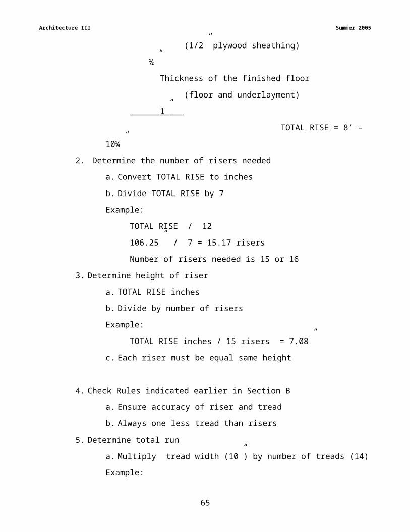
APPENDIX E7962 DRAFTING ARCHITECTURE II EVALUATION FORM
Your suggestions and insights are needed to improve our curriculum products including the curriculum guide, recommended activities, performance assessments, blueprint, test-item bank, and reference media. Please review all the Drafting – Architectural II curriculum materials carefully. After teaching one full course cycle, please take the time to fill out and return this evaluation form. Note that the more specific and clear your suggestions are, the more useful and influential they will be. You may wish to have an industry representative evaluate the products. Thank you for helping us serve you and your students better.
Rate the following statements from 1-5, with 1 being poor and 5 being excellent. When responding to specific curriculum content found within the curriculum guide or blueprint, please give competency and objective numbers. Teacher's Name: _______________________________________
School Name: _______________________________________ Don't Very Know Poor Fair Good Good
Excellent
1) Blueprint is well structured and focuses on essential Unsure 1 2 3 4 5concepts and skills. It does not contain superfluous content.Comments:
2) Curriculum guide clearly specifies the content Unsure 1 2 3 4 5needed to achieve program mastery. It is easy to useand is technically correct. Comments:
3) Curriculum incorporates appropriate math, science, Unsure 1 2 3 4 5technical concepts, and processes. Content is not too complex or too simple for students. It is technically correct.Comments:
4) Curriculum reflects the use of state-of-the-art Unsure 1 2 3 4 5technology. Equipment list reflects state-of-theart technology and meets minimum standards.Comments:
5) Program completers are well prepared for entry level Unsure 1 2 3 4 5 position in industry and/or post-secondary studies.Comments:
Return To: Tom ShownInstructional Technology & Human Services Phone: 919-807-38806360 Mail Service Center Fax: 919-807-3899
Raleigh, N.C. 27699-6360 [email protected].
69