forest wind project project description for eoi submissions
TRANSCRIPT

© Siemens Gamesa Renewable Energy S.A. (2020)
Forest Wind Project
Project description for EOI submissions
April 2020
Forest Wind –Project description for EOI submission
© Siemens Gamesa Renewable Energy S.A. (2020)
2/21
DISCLAIMER
This document has been prepared to support the development of EOI for the project. It contains extracts of
the Planning Report that was prepared by CleanSight on behalf of Forest Wind Holdings Pty Limited in
December 2019.
The information in this document is preliminary and likely to change as the project progresses in its
development.
This document or embodiment of it in any media and the information contained in it are the property of
Siemens Gamesa Renewable Energy S.A.. It is an unpublished work protected under the copyright laws free of
any legal responsibility for errors or omissions. It is supplied in confidence and it must not be used without the
express written consent of Siemens Gamesa Renewable Energy S.A. for any other purpose than that for which
it is supplied. It must not be reproduced in whole or in part in any way (including reproduction as a derivation
work) nor loaned to any third party. This document must be returned to Siemens Gamesa Renewable Energy
S.A. on demand

Forest Wind –Project description for EOI submission
© Siemens Gamesa Renewable Energy S.A. (2020)
1. PROJECT SUMMARY ................................................................................................... 1
Table 1 Summary of the proposed development ......................................................................................................................... 1 1.1. Project objectives ....................................................................................................................... 2 1.2. Applicant and EPC contractor .................................................................................................... 2 1.3. Siemens Gamesa background and Procurement Approach...................................................... 2
2. GENERA DESCRIPTION ............................................................................................... 3
3. LAYOUT AND DESIGN ................................................................................................. 3
3.1. Final design and micro-siting...................................................................................................... 4
4. WIND TURBINES ........................................................................................................... 4
Table 1 - Key wind turbine specifications .................................................................................................................................... 4
5. WIND TURBINE FOUNDATIONS .................................................................................. 4
6. CRANE HARDSTAND AND LAYDOWN AREAS .......................................................... 5
7. SUBSTATIONS AND DISTRIBUTION LINES ................................................................ 5
7.1. Overview..................................................................................................................................... 5 7.2. Substations ................................................................................................................................. 5 Table 2 - Substations 6 7.3. Battery storage facility ................................................................................................................ 6 7.4. Distribution Lines ........................................................................................................................ 7 7.5. Transmission Line ...................................................................................................................... 7 7.6. Vehicular access ........................................................................................................................ 7 7.6.1 Access roads 7 7.6.2 On-site access tracks ......................................................................................................................................................... 7 7.7. Operations compounds .............................................................................................................. 8 7.7.1 Primary Operations Compound .......................................................................................................................................... 8 7.7.2 Secondary Operations Compounds (north and south) ........................................................................................................ 8 7.8. Utilities ........................................................................................................................................ 9 7.8.1 Water supply 9 7.8.2 Wastewater treatment ........................................................................................................................................................ 9 7.8.3 Power supply 9 7.9. Chemical storage ....................................................................................................................... 9 7.10. Meteorological masts ................................................................................................................. 9 Table 3 - Summary of key infrastructure required during the operations phase ........................................................................... 9
8. CONSTRUCTION PHASE ........................................................................................... 12
8.1. Staging and sequencing ........................................................................................................... 12 8.2. Construction program ............................................................................................................... 12 8.3. Construction sequencing .......................................................................................................... 13 8.4. Construction site entrances ...................................................................................................... 13 8.4.1 Site entrance (Primary) .................................................................................................................................................... 13 8.4.2 Other Site entrances ........................................................................................................................................................ 14 8.5. Possible river transport ............................................................................................................. 14 8.6. Construction Compounds ......................................................................................................... 14 8.6.1 Construction Compound (Primary) ................................................................................................................................... 14 8.6.2 Construction Compounds (Secondary)............................................................................................................................. 14 8.6.3 Construction Compound (Tertiary) ................................................................................................................................... 15 8.7. Construction resources ............................................................................................................ 15

Forest Wind –Project description for EOI submission
© Siemens Gamesa Renewable Energy S.A. (2020)
8.7.1 Construction water supply ................................................................................................................................................ 15 8.7.2 Concrete batching plants ................................................................................................................................................. 15 8.7.3 Precast Concrete Tower Factory and Storage .................................................................................................................. 16 8.8. Transmission Line construction method ................................................................................... 16 8.8.1 Phase 3 conductor and earth wire stringing ..................................................................................................................... 16 8.8.2 Transmission tower foundations ....................................................................................................................................... 17 8.9. Summary of construction facilities ............................................................................................ 17 Table 4 - Summary of construction facilities .............................................................................................................................. 17 9. Construction workforce ............................................................................................................. 19 9.1. Equipment and machinery........................................................................................................ 19 9.2. Construction management ....................................................................................................... 19 9.2.1 Construction management plan ....................................................................................................................................... 19 9.2.2 Clearing native vegetation ................................................................................................................................................ 20 9.2.3 Air quality ............................................................................................................................................................... 20 9.2.4 Erosion and sediment control ........................................................................................................................................... 20 9.2.5 Waste management ......................................................................................................................................................... 20 9.2.6 Hours of work ............................................................................................................................................................... 21 9.2.7 Safety ............................................................................................................................................................... 21
10. OPERATIONAL CONSIDERATIONS .......................................................................... 21
10.1. Wind farm operations ............................................................................................................... 21 10.2. Operational workforce .............................................................................................................. 21 10.3. Maintenance ............................................................................................................................. 22
Forest Wind –Project description for EOI submission
© Siemens Gamesa Renewable Energy S.A. (2020)
1/21
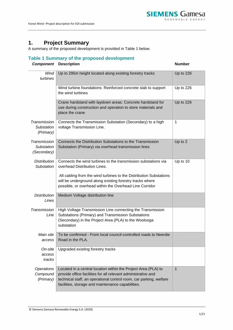
1. Project Summary A summary of the proposed development is provided in Table 1 below.
Table 1 Summary of the proposed development Component Description Number
Wind
turbines
Up to 295m height located along existing forestry tracks Up to 226
Wind turbine foundations: Reinforced concrete slab to support
the wind turbines
Up to 226
Crane hardstand with laydown areas: Concrete hardstand for
use during construction and operation to store materials and
place the crane
Up to 226
Transmission
Substation
(Primary)
Connects the Transmission Substation (Secondary) to a high
voltage Transmission Line.
1
Transmission
Substation
(Secondary)
Connects the Distribution Substations to the Transmission
Substation (Primary) via overhead transmission lines
Up to 2
Distribution
Substation
Connects the wind turbines to the transmission substations via
overhead Distribution Lines.
All cabling from the wind turbines to the Distribution Substations
will be underground along existing forestry tracks where
possible, or overhead within the Overhead Line Corridor
Up to 10
Distribution
Lines
Medium Voltage distribution line
Transmission
Line
High Voltage Transmission Line connecting the Transmission
Substations (Primary) and Transmission Substations
(Secondary) in the Project Area (PLA) to the Woolooga
substation
Main site
access
To be confirmed - From local council-controlled roads to Neerdie
Road in the PLA.
On-site
access
tracks
Upgraded existing forestry tracks
Operations
Compound
(Primary)
Located in a central location within the Project Area (PLA) to
provide office facilities for all relevant administrative and
technical staff, an operational control room, car parking, welfare
facilities, storage and maintenance capabilities.
1

Forest Wind –Project description for EOI submission
© Siemens Gamesa Renewable Energy S.A. (2020)
2/22
Component Description Number
Operations
Compound
(Secondary)
Located to the north and south of the Project Area (PLA)
providing storage areas for plant, equipment and materials,
maintenance and workshop areas, wash down facilities as well
as parking and amenities
2
Battery
storage
Battery storage facilities (subject to feasibility), relocatable
offices, fencing
4
Potable
water supply
Provision of water to site entrances and Operations Compounds At each
compound
Wastewater
treatment
On-site wastewater treatment and disposal or removal At each
compound
Power
supply
Power supply to the site entrance and operations compounds At each
compound
Chemical
storage
Chemical storage facility and Operations Compounds At each
compound
1.1. Project objectives The objectives of the Project are to:
• install up to 226 wind turbines (around 1200MW)
• contribute up to one quarter of the Queensland Government’s commitment of 50% renewable
energy by 2030
• deliver low cost energy below the conventional electricity market
• offset up to approximately 3 million tonnes of carbon dioxide equivalent each year, and
• deliver significant wider economic and social returns, including infrastructure investment, job
creation and industry innovation.
1.2. Applicant and EPC contractor The Proponent for the Project is Forest Wind Holdings Pty Limited, a joint venture between
CleanSight and Siemens Project Ventures GmbH. The EPC contractor is Siemens Gamesa
Renewable Energy (Siemens Gamesa).
1.3. Siemens Gamesa background and Procurement Approach Siemens Gamesa is a global leading provider of wind power products & service solutions, it ranks 1st
in Offshore wind power solutions, 2nd in Onshore wind power solutions, and 2nd in service (considering
service backlog and fleet size); Siemens Gamesa has over 101GW of installed capacity and with over
40 years’ experience in the onshore wind power business, Siemens Gamesa is the technological
partner of choice for Onshore wind power projects.
The company was founded in April 2017 as a merger of Siemens Wind Power and Gamesa, it has
over 50 sales offices in 39 countries. In Australia Siemens Gamesa has 10+ operational projects, with
multiple currently under construction.

Forest Wind –Project description for EOI submission
© Siemens Gamesa Renewable Energy S.A. (2020)
3/22
Siemens Gamesa is committed to develop long term relationships with vendor and communities. In
the Forest Wind project Siemens Gamesa aims to utilise local, Queensland and Traditional Owner
content in the supply of goods and services in the construction and operation of the Project, where it
is technically, commercially and financially feasible and competitive to do so. Specifically, in this
project Siemens Gamesa aims to:
• maximise opportunities for suppliers from Wide Bay and Queensland to service the Project
• maximise training and employment opportunities for Butchulla and Kabi Kabi First Nation
Peoples (the Project land area’s Traditional Owners)
• provide opportunities for training, apprenticeships and innovation.
Suppliers and vendors will be required to comply with key company policies including Code of
Conduct, HSE, Risk Management and others.
Siemens Gamesa strongly encourage local industry to contact ICN Queensland in the first instance to
improve their understanding of the EOI process. Work packages will be published in the ICN Gateway
project page.
Siemens Gamesa primary contact is by email. Please forward enquires to:
2. General Description On completion of construction, the Project will comprise wind turbines and related and ancillary uses
and infrastructure which may include the following:
• up to 226 wind turbines with a power capacity of up to 1,200MW
• substations and battery storage facilities
• Transmission Line and Distribution Lines
• vehicular access from main access points to the wind turbines using existing forestry tracks
• site entrances
• Operations compounds, and
• weather monitoring equipment.
3. Layout and design Nominal locations for up to 226 wind turbines within the Project Area (PLA) and alternative wind
turbine locations every 100-200m have been identified. The final siting of each wind turbine (up to a
total of 226) will be determined with consideration of a range of constraints and will not be located
more than 100m from any of the nominal or alternative locations included in Development Permit
(1912-14632 SDA). The constraints to be considered include the following:
• stakeholder requirements, including the requirements of the Plantation Licensee
• ecology
• stormwater management
• cultural heritage
• proximity to waterways
• electromagnetic interference (EMI)
• aviation
• existing infrastructure such as gazetted roads and power lines
• wind resource assessments, and
• location of sensitive land uses to achieve a 3km buffer from the wind turbines to the sensitive
receptor.

Forest Wind –Project description for EOI submission
© Siemens Gamesa Renewable Energy S.A. (2020)
4/22
3.1. Final design and micro-siting Once on site, prior to construction, a final on-ground assessment shall be undertaken to ground truth
and micro-site each wind turbine taking into consideration each of the following constraints:
• ecology - presence of protected flora (in particular, Macrozamia pauli-guilielmi), or individual
habitat features such as hollow bearing trees
• cultural heritage - avoidance of high-risk areas or features
• drainage lines - presence of the Plantation Licensee’s specific drainage infrastructure or other
erosion and sediment control measures
• EMI constraints outlined in the Electromagnetic Interference Impact Assessment Report to:
o ensure wind turbines are not located within the second Fresnel zones of fixed point to
point microwave links
o radio link services -- to avoid micro-siting wind turbines into radio link paths
• location of sensitive land uses ensuring a minimum separation distance of 3km from the
nearest wind turbine is achieved, and
• the Plantation Licensee’s operational requirements.
During the micro-siting process the wind turbines will not be located more than 100m from any of the
nominal or alternative locations included in Development Permit (1912-14632 SDA)..
4. Wind turbines The Project Area (PLA) will accommodate up to 226 wind turbines, each with a capacity to generate
up to 6MW (+/- 3MW) of electricity, with a maximum height to blade tip of up to 295 m above the base
of the wind turbine tower. The wind turbines will be located along existing forestry tracks.
The wind turbines will be of the horizontal axis type, with a rotor consisting of three blades that will be
designed, type certified and manufactured to comply with appropriate Australian Standards and the
International Electrotechnical Commission (IEC 61400) requirements. The rotor blades will be
mounted to the wind turbine hub at an appropriate height to allow for the maximum height to blade tip
of 295m not to be exceeded. The rotor blades, nacelle and upper sections of the wind turbine tower
will be coloured a shade of white with a semi-matte finish in order to minimise reflection and visual
impact yet provide adequate contrast to background as specified in the Aviation Impact Assessment.
Company logos will not be displayed.
Table 1 - Key wind turbine specifications Feature Specification
Project generation capacity Up to 1200MW
Wind turbine electrical output 6MW (+/-3MW)
Number of wind turbines Up to 226
Blade tip height Up to 295m
5. Wind turbine foundations The construction of each wind turbine foundation will comprise a reinforced concrete slab that is
constructed adjacent to the wind turbine crane hardstand. The actual amount of concrete will vary in
size depending on imposed loadings, ground conditions, construction methodology and the drainage
design. Where possible, the excavated material for foundations will be reinstated following
construction, however, construction of each wind turbine foundation is likely to result in surplus

Forest Wind –Project description for EOI submission
© Siemens Gamesa Renewable Energy S.A. (2020)
5/22
material, which will be reused on site for construction and maintenance of access tracks, wind turbine
crane hardstands, laydown and compounds, landscaping and potentially by the Plantation Licensee to
improve soil quality or backfill unused excavations from former forestry activities.
6. Crane hardstand and laydown areas The wind turbines will require an area of hardstand adjacent to the wind turbine foundation to provide
a stable base on which to place wind turbine components ready for assembly and erection, and to
locate the cranes necessary to lift the wind turbine components into place. The tower, nacelle, hubs
and rotor blades will be installed with cranes (which may be a mobile tyred crane, crawler crane
and/or tower cranes). The optimisation of lifting plans and crane requirements will at a minimum be a
function of operational requirements, availability and cost of cranes, wind turbine make, model and
configuration, tower type, terrain and earth moving costs, erecting times, environmental and plantation
related constraints and schedule. The hardstand and laydown areas will typically comprise:
• foundation area
• main crane hardstand
• assist crane hardstand
• component storage area
• boom assembly hardstand
• ballast lay down area
• working areas, and
• platforms – storage of materials and tools for installation and commissioning.
The hardstand and laydown area footprint will be up to 10,000m2 in area, subject to site-specific
constraints at each location, with dimensions in the order of 200x50m or 100x100m, requiring clearing
of plantation forest to facilitate their construction. The hardstand and laydown areas will be left in
place following construction for ongoing operational and maintenance requirements.
7. Substations and Distribution Lines
7.1. Overview The wind turbines typically generate at around 690V electricity and have a step-up transformer either
within the tower internally or externally on the wind turbine foundation. The stepped-up voltage at the
wind turbine may be between 11kV and 66kV. The generated electricity will be distributed in
conductors within the Project Area (PLA) via underground and overhead Distribution Lines to a series
of substations as outlined below.
7.2. Substations There are three types of Substations to be installed as part of the Project Area (PLA):
• Primary fixed substation (Transmission Substation (Primary)) - connects the Transmission
Substation (Primary) toa high voltage Transmission Line.
• Secondary fixed substation (Transmission Substation (Secondary)) - connects Distribution
Substations to the Transmission Substation (Primary) - together these two form the
Transmission Substations
• Distribution substation (Distribution Substation) – steps up the voltage of the wind turbines for
connection to the Transmission Substations. - together these three form the Substations
Table 2 provides details of the Substations that will be installed within the Project Area (PLA). The
final location will be subject to the staging program and agreement with the State as landowner and
the Plantation Licensee as the primary land user. The perimeter of each substation will be secured
with a security fence and lockable gate.

Forest Wind –Project description for EOI submission
© Siemens Gamesa Renewable Energy S.A. (2020)
6/22
Table 2 - Substations
Substation
name
Description Number of
substations
Specification Footprint
Transmission
Substation
(Primary)
— Increases voltage and connects Distribution Substations and the Transmission Substations (Secondary) to a high voltage Transmission Line. — To include the main transformer, switchgear, protection, metering, associated electrical
1 Transform up
to 275kV
c. 6.25
ha
Transmission
Substations
(Secondary)
— Increases voltage and connects the
Distribution Substations to the
Transmission Substations (Primary) via
an overhead Transmission Line.
Up to 2
Transform up
to 275kV
c. 4 ha
Distribution
Substations
— Connects the wind turbines to the
Transmission Substations via
Distribution Lines
— All cabling from the wind turbines to
the Distribution Substations will be
underground along existing forestry
tracks where possible, or overhead
within the Overhead Transmission
Corridor (OTC) (PLA)
— The location of the Distribution
Substations will be confirmed prior to
construction commencing. The final
location will be subject to the final
staging program and agreement with
the Plantation Licensee.
— Include substations to feed the
Timber Processors and/or connect to
the Energy Queensland (Ergon and
Energex) networks (Dedicated
Distribution Substations)
Up to 10
Transform up
to 66 kV
c. 1 ha
7.3. Battery storage facility Up to four battery storage facilities for storage of electricity may be located adjacent to the
Substations. Each battery storage facility would have a footprint of up to 4 ha and include
transformers, switchgear, operations rooms, parking and facilitate the construction, operation,
charging, discharging, exchanging and upgrading as battery technology develops, for use by the
Project, local industry and connection to supply the NEM.

Forest Wind –Project description for EOI submission
© Siemens Gamesa Renewable Energy S.A. (2020)
7/22
7.4. Distribution Lines Distribution Lines will be installed within the Project Area (PLA) to connect wind turbines to
Substations and will be underground along existing forestry tracks or overhead within the Overhead
Transmission Corridor (OTC). Up to 450km of underground cables will be laid in cable trenches
approximately 0.5m to 1.5m in width with a minimum depth of 800mm to enable forestry activities to
continue after installation. The majority of the cable trenches will be located under or adjacent to the
existing onsite access tracks to minimise forestry impacts, vegetation clearing and additional
construction activities. Where overhead, the Distribution Lines will be connected by a series of
individual poles and be of sufficient height to allow for site vehicles to pass beneath in accordance
with the requirements of the Queensland Electricity Safety Regulation, 2013.
7.5. Transmission Line The Transmission Line will run from the northern Transmission Substation (Secondary) to the
Transmission Substation (Primary) and from the Transmission Substation (Primary) to the southwest
corner of the Project Area (PLA) within the OTC and then on to Powerlink Corporation’s Woolooga
Substation within an OTC(non-PLA). The location of the OTC (non-PLA) is currently under design..
The Transmission Line will comprise transmission towers, conductors, earth wires and insulators.
7.6. Vehicular access
7.6.1 Access roads
The main access to the Project Area (PLA) will be via local council-controlled roads between the
Bruce Highway and the Project Area. Secondary access points will be provided to access the
Operations Compounds from Tin Can Bay Road and Maryborough Cooloola Road, both State-
controlled Roads, and Maryborough Tuan Forest Road, a FCRC controlled road.
7.6.2 On-site access tracks
The existing pine plantation has an extensive road and track network that will also be used by the
Project. The tracks to be used for access will be determined through consultation with the Plantation
Licensee and construction contractors prior to and during construction, in order to minimise impacts
on plantation activities. Options will be available to modify the tracks being used when wet weather
and ground conditions require. A number of the existing tracks within the plantation will require
upgrading and widening to enable the wind turbine components to be delivered and for the
underground cables to be installed. Subject to resolution with the State and Plantation Licensee as to
which forestry tracks will be used within the Project Area (PLA), there are currently anticipated to be
approximately six small bridges located on existing access tracks that may need reinforcing or
replacing, and approximately 15 culverts on tracks that may need to be replaced for use during
construction. The upgrade to the bridge and culvert crossings will be undertaken in consultation with
the Plantation Licensee and relevant regulators and the necessary approvals obtained prior to work
commencing. As far as reasonably practical, all access tracks shall be modified in accordance with
the following design criteria and mitigation measures, and any additional design specifications will be
agreed with the State and the Plantation Licensee:
• The forestry tracks may be upgraded to be typically 4-6m wide and may be expanded by 1m
to accommodate crane and delivery vehicle requirements during construction, allow for the
installation of underground cabling.
• Regular passing places and turning areas on existing forestry tracks will be established.
• Tracks will be constructed from locally sourced aggregate wherever possible.
• Sediment-laden run-off will be managed in accordance with the Stormwater and Erosion and
Sediment Control Strategy.
Forest Wind –Project description for EOI submission
© Siemens Gamesa Renewable Energy S.A. (2020)
8/22
• Once the Project has been commissioned, access tracks greater than 6m wide will be
reduced with the edges dressed back in accordance with specifications to be agreed with the
State and the Plantation Licensee.
• The number of water course crossings will be minimized and will be limited to existing
crossings. The exact requirement and design of the water course crossings will be agreed
during the detailed design phase and will be based on detailed site investigations and through
discussions with the State and the Plantation Licensee. All necessary approvals for waterway
crossings will be obtained prior to works commencing.
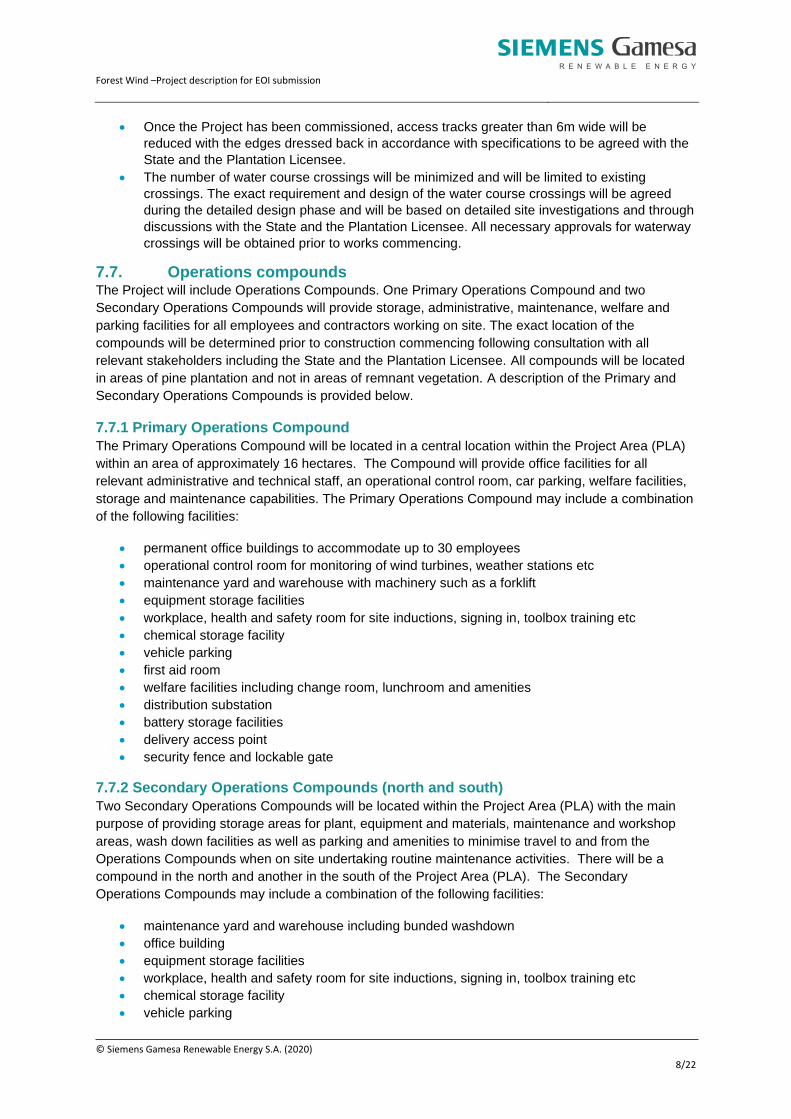
7.7. Operations compounds The Project will include Operations Compounds. One Primary Operations Compound and two
Secondary Operations Compounds will provide storage, administrative, maintenance, welfare and
parking facilities for all employees and contractors working on site. The exact location of the
compounds will be determined prior to construction commencing following consultation with all
relevant stakeholders including the State and the Plantation Licensee. All compounds will be located
in areas of pine plantation and not in areas of remnant vegetation. A description of the Primary and
Secondary Operations Compounds is provided below.
7.7.1 Primary Operations Compound
The Primary Operations Compound will be located in a central location within the Project Area (PLA)
within an area of approximately 16 hectares. The Compound will provide office facilities for all
relevant administrative and technical staff, an operational control room, car parking, welfare facilities,
storage and maintenance capabilities. The Primary Operations Compound may include a combination
of the following facilities:
• permanent office buildings to accommodate up to 30 employees
• operational control room for monitoring of wind turbines, weather stations etc
• maintenance yard and warehouse with machinery such as a forklift
• equipment storage facilities
• workplace, health and safety room for site inductions, signing in, toolbox training etc
• chemical storage facility
• vehicle parking
• first aid room
• welfare facilities including change room, lunchroom and amenities
• distribution substation
• battery storage facilities
• delivery access point
• security fence and lockable gate
7.7.2 Secondary Operations Compounds (north and south)
Two Secondary Operations Compounds will be located within the Project Area (PLA) with the main
purpose of providing storage areas for plant, equipment and materials, maintenance and workshop
areas, wash down facilities as well as parking and amenities to minimise travel to and from the
Operations Compounds when on site undertaking routine maintenance activities. There will be a
compound in the north and another in the south of the Project Area (PLA). The Secondary
Operations Compounds may include a combination of the following facilities:
• maintenance yard and warehouse including bunded washdown
• office building
• equipment storage facilities
• workplace, health and safety room for site inductions, signing in, toolbox training etc
• chemical storage facility
• vehicle parking

Forest Wind –Project description for EOI submission
© Siemens Gamesa Renewable Energy S.A. (2020)
9/22
• first aid room
• welfare facilities including change room, lunchroom and amenities
• Distribution Substation
• battery storage facilities
• security fence and lockable gate
7.8. Utilities All Operations Compounds will be serviced by relevant utilities as outlined below.
7.8.1 Water supply
Rainwater tanks will be installed at all Operations Compounds to provide water for amenities,
washdown and maintenance purposes as required and supplemented by water tankers if necessary.
Water will be treated to a potable standard where necessary. A supply of water for firefighting
purposes will be maintained in accordance with provisions agreed with the Plantation Licensee.
7.8.2 Wastewater treatment
On-site sewage treatment and effluent disposal or pump out facilities will be installed at the
Operations Compounds as required, in accordance with the relevant local and State statutory
requirements.
7.8.3 Power supply
An internal electrical supply will be provided to service the Operations Compounds by way of
Distribution Lines, on routes to be agreed with the State and Plantation Licensee. Options for power
supply from solar panels with battery storage and diesel generators may be utilised.
7.9. Chemical storage Dedicated chemical storage facilities will be constructed at the relevant Operations Compounds. All
chemical storage areas will be bunded and have a roof and will be constructed in accordance with
AS1940: The storage and handling of flammable and combustible liquids.
7.10. Meteorological masts Up to three temporary and six permanent meteorological masts (or LIDAR devices) will be installed
within the Project Area (PLA), in accordance with the provisions detailed in the International
Electrotechnical Commission (IEC) 61400-12-1 Guidelines for power performance testing.
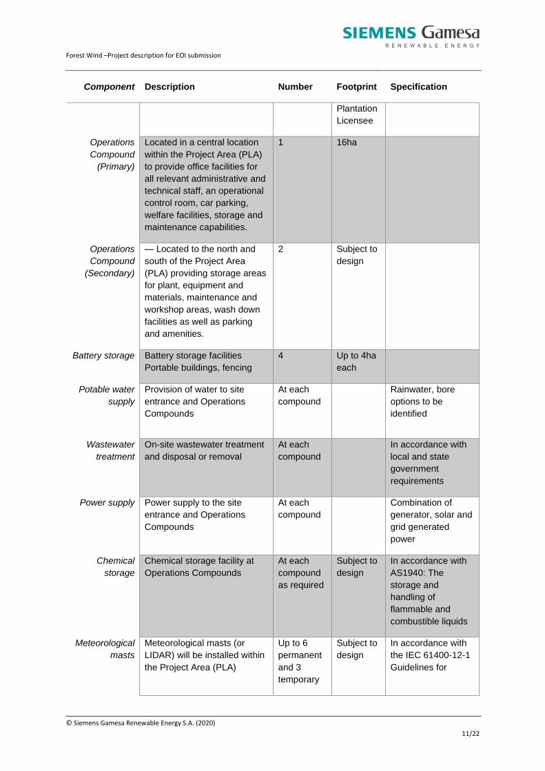
7.11. Summary Table 3 provides a summary of the key aspects that form part of the operations phase of the Project.
Table 3 - Summary of key infrastructure required during the operations phase
Component Description Number Footprint Specification
Wind turbines Up to 295m height located
along existing forestry tracks
Up to 226 c. 6MW (+/- 3MW),
to produce a total
electricity
generation of up to
1200 MW
Wind turbine foundations:
Reinforced concrete slab to
support the wind turbines
Up to 226 ~900 m2
Crane hardstand with laydown
areas: a mixture of concrete
Up to 226 c. 1 ha

Forest Wind –Project description for EOI submission
© Siemens Gamesa Renewable Energy S.A. (2020)
10/22
Component Description Number Footprint Specification
and gravel hardstand for use
during construction and
operation to store materials
and place the crane
Transmission
Substation
(Primary) fixed
Connects the Transmission
Substation (Secondary) to the
Transmission Line
1 c. 6.25ha Up to 275Kv
Transmission
Substation
(Secondary)
fixed
Connects the Distribution
Substations to the
Transmission Substation
(Primary) via an overhead
Transmission Line.
Up to 2 c. 4ha
Up to 275KV
Distribution
Substation
Connects the wind turbines to
the Transmission Substations
All cabling from the wind
turbines to the Distribution
Substations will be
underground along existing
forestry tracks where
possible, or overhead within
the OTC.
Up to 10 c. 1ha
Up to 66 kV
Distribution
Lines
Underground cables connecting the turbines to the Distribution Substations
Overhead distribution lines within the OTC from the Transmission Substation (Secondary) fixed in the north to the Transmission Substation (Primary)
High Voltage
Transmission
Line
Connects the Transmission
Substations (Primary) and
Transmission Substations
(Secondary) in the Project
Area (PLA) to Woolooga
Substation
Approx.
65km in
length
Main site
access
Local council-controlled roads
to Neerdie Road in the PLA
(to be confirmed)
On-site access
tracks
Upgraded existing forestry
tracks
Subject to
agreement
with the
Forest Wind –Project description for EOI submission
© Siemens Gamesa Renewable Energy S.A. (2020)
11/22
Component Description Number Footprint Specification
Plantation
Licensee
Operations
Compound
(Primary)
Located in a central location
within the Project Area (PLA)
to provide office facilities for
all relevant administrative and
technical staff, an operational
control room, car parking,
welfare facilities, storage and
maintenance capabilities.
1
16ha
Operations
Compound
(Secondary)
— Located to the north and
south of the Project Area
(PLA) providing storage areas
for plant, equipment and
materials, maintenance and
workshop areas, wash down
facilities as well as parking
and amenities.
2 Subject to
design
Battery storage Battery storage facilities
Portable buildings, fencing
4 Up to 4ha
each
Potable water
supply
Provision of water to site
entrance and Operations
Compounds
At each
compound
Rainwater, bore
options to be
identified
Wastewater
treatment
On-site wastewater treatment
and disposal or removal
At each
compound
In accordance with
local and state
government
requirements
Power supply Power supply to the site
entrance and Operations
Compounds
At each
compound
Combination of
generator, solar and
grid generated
power
Chemical
storage
Chemical storage facility at
Operations Compounds
At each
compound
as required
Subject to
design
In accordance with
AS1940: The
storage and
handling of
flammable and
combustible liquids
Meteorological
masts
Meteorological masts (or
LIDAR) will be installed within
the Project Area (PLA)
Up to 6
permanent
and 3
temporary
Subject to
design
In accordance with
the IEC 61400-12-1
Guidelines for

Forest Wind –Project description for EOI submission
© Siemens Gamesa Renewable Energy S.A. (2020)
12/22
Component Description Number Footprint Specification
power performance
testing.
8. Construction Phase
8.1. Staging and sequencing The Project may be constructed in a series of stages, the timing of which will be dependent on the
requirements of commercial and legal agreements with relevant stakeholders including the State, the
Plantation Licensee, First Nations people, Powerlink and the buyers of the electricity. Each
stakeholder has specific requirements that will determine the timing and location of the final staging
which cannot be governed by the Proponent alone. The staging of the works will also be influenced by
market need which will dictate the number of wind turbines and program of installation for installed in
each stage.
An indicative potential staging program is as follows:
• Phase 1: Up to 100 wind turbines (c. 600MW) to connect from the Transmission Substation
(Primary) to Woolooga Substation on a double circuit Transmission Line. Installation of the
Transmission Line and connection to the Woolooga Substation will occur in this phase. Phase
1 will include the construction of a secondary Transmission Substation. Phase 1 may include
multiple stages.
• Phase 2: up to 100 additional wind turbines to bring the total wind farm capacity to 200 wind
turbines (cumulative c. 1200MW) connected to existing Transmission Substations constructed
in an earlier stage.
8.2. Construction program The overall duration of construction will depend on the stage approach and technology used.
Approximate timeframes for each stage would include an equipment supply lead period of six to nine
months plus a further period within which approximately six to eight wind turbines would be
constructed per month. For example, a stage with 100 wind turbines would take ~8 months plus 100/6
(~16 months), being a total of ~24 months.
The likely maximum workforce on site at any one time will be hundreds of people. Construction
facilities will be provided for the duration of the construction phase to support the workers and the
Project. The construction facilities include Construction Compounds, utility services, concrete
batching plants and a potential pre-cast concrete tower factory.
Stage 1 will include the establishment of key related and ancillary uses and infrastructure that will be
required throughout the construction phase and include the following:
• main site entry compound
• Construction Compounds
• Substations
• Distribution Lines
• Transmission Line
• establishment of construction support facilities e.g. concrete batching plant, construction
water supply, precast concrete tower factory (subject to feasibility), and
• meteorological masts.

Forest Wind –Project description for EOI submission
© Siemens Gamesa Renewable Energy S.A. (2020)
13/22
8.3. Construction sequencing The sequencing of construction activities in each stage will be determined by the construction
contractor in consultation with the Plantation Licensee in order to minimise impacts on harvesting and
haulage of timber products. It is anticipated that the works will include the following:
• site survey
• cultural heritage survey and clearance (or mitigation) as necessary
• flora and fauna pre-clearing assessment as necessary
• vegetation clearing as required, where the Plantation Licensee will clear pine product and the
contractor clears other vegetation as required
• de-stumping cleared pine by contractor
• site establishment, including Construction Compound and utilities
• installation of a High Voltage Transmission Line, including the following:
o relevant civil works for transmission tower and surrounding construction pad
o construction of the towers
o line stringing
o connect to substation(s)
• construction of wind turbine strings
o installation of erosion and sediment control requirements
o installation of Distribution Lines and upgrade of existing forestry access tracks as
necessary (either parallel or in series)
o excavation for hardstands and foundation construction
o spoil from earthworks redistributed to hardstands or access track upgrades
o preparation of foundations, installation of reinforcing bar and formwork and pouring
concrete
o delivery of components
o erection of wind turbines
• installation of substation/s and overhead lines and commissioning, if required
• commissioning and reliability testing of wind turbines
• rehabilitation and restoration activities as necessary, and
• removal of temporary Construction Compounds and facilities.
Construction periods will be subject to any weather delays, availability of resources and performance
of contractors.
8.4. Construction site entrances During the construction phase there will be a number of site entrances as follows:
• Primary construction site entrance located in the southwest of the plantation. All large and
oversized wind turbine components will enter the Site through this site entrance.
• Secondary construction site entrances located to the north, south and east of the Site at
locations determined prior to construction commencing and subject to agreement with the
Plantation Licensee
8.4.1 Site entrance (Primary)
The Site Entrance (Primary) during construction will include the following:
• office buildings
• first aid room(s), induction/training room(s)
• welfare facilities including change rooms, lunchrooms and restrooms
• vehicle parking and equipment storage.
The Project’s oversize components, including the wind turbine’s nacelle, blades, hub, towers and
main transformers, may be delivered to the Port of Brisbane. From there they would be transported up
Forest Wind –Project description for EOI submission
© Siemens Gamesa Renewable Energy S.A. (2020)
14/22
the Port of Brisbane Motorway (M42), onto the Gateway Motorway (M1), merge with the Bruce
Highway (M1) at South Pine and travel to Neerdie Road in the Plantation License Area via local
council-controlled roads. Access to the site will be 24 hours a day/ 7 days a week.
8.4.2 Other Site entrances
In order to minimise worker travel to relevant sections of the Project Area (PLA), construction site
entrances will be located to the north, south and east using existing forestry access points. The
location of the entrances will be determined prior to construction in accordance with the Plantation
Licensee requirements. The secondary site construction entrances will be used for the delivery of
equipment and materials and for employees to access the Project Area (PLA) and will not involve
vehicles larger than the logging vehicles currently using the access points.
8.5. Possible river transport The potential for large and oversize components to be delivered by barge on the Mary River to the
Beaver Rock Boat Ramp area and then transported by truck to the Project Area (PLA) is being
investigated.
8.6. Construction Compounds There will be three types of fenced Construction Compounds within the Project Area (PLA) during the
construction phase, as follows:
• Construction Compound (Primary) – at a central location within the Project Area (PLA)
• Construction Compound (Secondary) – located generally to the north and south to service
each stage
• Construction Compound (Tertiary) – to service each string of wind turbines.
Locations of the Construction Compounds will be confirmed in consultation with the Plantation
Licensee. All compounds will be located in areas of pine plantation and not remnant vegetation.
Each of the compounds are described below.
8.6.1 Construction Compound (Primary)
The Construction Compound (Primary) will be constructed at a central location within the Project Area
(PLA) and will be subject to final approval by the Plantation Licensee prior to construction
commencing. The compound may include the following within a fenced compound:
• up to 15 portable buildings for administrative and technical staff
• car parking
• equipment and machinery storage
• workplace health and safety and welfare facilities
• induction room, and
• utilities.
The Principal’s site office will be co-located at this compound.
8.6.2 Construction Compounds (Secondary)
The Construction Compounds (Secondary) will be for the use of construction staff within each stage
of the works and may include the following within a fenced compound:
up to four portable buildings for office and workplace health and safety purposes
• car parking
• welfare facilities
• concrete batching plant
• parts assembly

Forest Wind –Project description for EOI submission
© Siemens Gamesa Renewable Energy S.A. (2020)
15/22
• equipment and machinery storage
• storage of spare parts
• machinery maintenance facilities
• chemical storage, and
• utilities.
8.6.3 Construction Compound (Tertiary)
The Construction Compounds (Tertiary) will be temporary and will support the construction of each
string of wind turbines. They will comprise up to two portable buildings and provide basic office
capabilities, utilities, welfare facilities and a first aid room for use by the construction staff and
contractors.
8.7. Construction resources
8.7.1 Construction water supply
Construction water will be used in the concrete batching process, for dust suppression and bulk
earthworks as necessary. Potable water will be required for amenities and drinking water supply for
the construction workforce. The provision of construction and potable water will be the responsibility
of the construction contractors and a water supply strategy will be required to be provided as part of
the Construction Management Plan prior to works commencing. A range of options are available to
secure water including the following:
• extract water from the Teddington Weir and pipe or truck it to the Construction Compounds or
to batch plants within the facility compounds – subject to consultation with the relevant
regulatory authorities
• bore water – subject to consultation with the relevant regulatory authorities and terms agreed
with the Plantation Licensee
• provision of rainwater tanks at the Construction Compounds for potable water use, and
• purchasing water from the mains supply network.
Other options not yet assessed include purchasing water from an existing water allocation from the
Mary River or treated wastewater effluent from Gympie or Maryborough municipal sewage treatment
plants.
The total water demand required for the construction of the Project Area (PLA) is currently under
assessment.
8.7.2 Concrete batching plants
Concrete batching plants will be required to manufacture concrete for the construction of wind turbine
footings and hardstands. It is anticipated that up to six concrete batch plants will be required to
produce up to 300,000 cubic meters of concrete per year. The batching plants will likely be located at
the Construction Compounds, with the final location confirmed prior to construction commencing. The
concrete batching plants will be bunded and, where possible, located on cleared, elevated land away
from drainage lines.
The footprint of each batching plant will be approximately 2.5 ha and will support the following:
• concrete truck loading hardstands
• loading bays
• hoppers
• cement and admixture silos
• water tank
• stockpiles for aggregate and sands, and
Forest Wind –Project description for EOI submission
© Siemens Gamesa Renewable Energy S.A. (2020)
16/22
• in-ground water recycling/first flush pit.
Sand and aggregate to produce concrete will be sourced either from on-site or from local suppliers
off-site. The area where the batching plants are located will be rehabilitated following the completion
of the construction program and returned to the Plantation Licensee for forestry if not required for
subsequent wind farm stages.
8.7.3 Precast Concrete Tower Factory and Storage
A factory may be located on site to make precast concrete tower sections. Sand and coarse
aggregates would be mixed with cement and other additives and poured into moulds with reinforcing
bar inside. Once set, the precast concrete segments will be stored at a neighbouring area awaiting
just-in-time delivery to a crane at the wind turbine site for installation.
The precast concrete factory would be approximately 4ha in area and would be a temporary structure,
possibly tent like, and include:
• truck loading hardstands
• loading bays
• hoppers
• cement and admixture silos
• water tank
• stockpiles for aggregate and sands
• in-ground water recycling/first flush pit
• overhead lifting equipment
• concrete mixing equipment
• reinforcing bar bending and positioning equipment
• computer numerical controlled grinding machines
• moulds
• offices
• diesel generators of up to 4MW
• communications mast, and
• precast segment storage hardstand.
The factory would be bunded. It would be rehabilitated following the completion of the construction
program and returned to the Plantation Licensee for forestry if no longer required for subsequent wind
farm stages.
8.8. Transmission Line construction method The following are key aspects to be undertaken during the construction of the high voltage
Transmission Line.
8.8.1 Phase 3 conductor and earth wire stringing
Conductors and earth wires will be erected using the ‘tension stringing’ method in which conductors
and earth wires are installed under sufficient tension to be kept clear of ground and mid-span
obstacles within the easement. A small diameter steel lead rope threaded onto specially designed
pulleys located on each pole will be used. This rope can be strung either by a small helicopter and
placed in the pulleys or by a vehicle dragging it along the corridor or easement and subsequently
lifting it into place. Once in place, high strength, non-rotating steel winch ropes are threaded through
the pulleys using a winch and a special braking device tensioner to keep the cable off the ground. The
conductors and earth wires are then threaded through the pulleys and connected to the insulators on
the poles.

Forest Wind –Project description for EOI submission
© Siemens Gamesa Renewable Energy S.A. (2020)
17/22
8.8.2 Transmission tower foundations
Transmission tower (steel lattice towers) foundations are grouped into three main types, broadly
described as bored, mass concrete and special. Bored or mass concrete foundations are normally
used whereas special foundations such as driven or screw piles are used where ground conditions do
not permit installation of the normal types.
Construction of tower foundations usually consists of the following steps:
• setting out
• excavation or boring
• leg stub or base set up
• placement of reinforcing steel and concrete, and
• backfilling of excavated foundations.
Setting out involves the placement of temporary pegs on site to mark the location of the excavation.
Dimensions of foundations are determined by the tower type, height and soil conditions at the site.
The soil and slope conditions are analysed as part of the geotechnical investigations and foundation
design undertaken by the geotechnical engineers prior to work commencing.
Excavation of bored foundation may be by truck mounted auger, backhoe or track mounted excavator
for mass concrete foundations. The excavation is bored at the same inclination as the tower leg. In
unstable ground conditions, the excavation may be stabilized by the insertion of a steel ‘liner’ in a
bored foundation, shoring or timbering for a mass concrete foundation. Although dependent upon the
geology of the surrounding soil, foundation may typically be excavated to a depth of approximately
8m.
Screw pile foundations are a single process installation that requires no pre-drilling, boring and limited
pile cap excavation. Driven foundation piles may also be adapted where swampy or unstable ground
conditions are encountered and where there is an environmental concern about the excavated spoil.
Reinforcing steel is normally required in tower foundations with the amount varying with tower and
foundation type. Temporary formwork is also used for the foundation column above the ground
(bored foundations) and above the base (mass concrete foundations). Concrete is placed in
accordance with normal construction procedures and formwork removed after an appropriate curing
time.
Backfilling of mass concrete foundations is completed using the excavated material if suitable or
imported fill. Surplus material is spread evenly about the site or removed, depending on quantity and
suitability.
8.9. Summary of construction facilities A summary of facilities required during the construction phase of the Project has been provided in
Table 4.
Table 4 - Summary of construction facilities
Component Description Number Footprint
Site Entrance
(Primary)
Located at southwest corner of Site,
within the plantation — Will include
-Office buildings
-First aid room(s), induction/training
room(s)
1 Subject to design (c.
1Ha)

Forest Wind –Project description for EOI submission
© Siemens Gamesa Renewable Energy S.A. (2020)
18/22
Component Description Number Footprint
- Welfare facilities including change
rooms, lunchrooms and restrooms
-Vehicle parking and equipment
storage
Site Entrance
(Secondary)
One each in the north, south and east
of the Project Area (PLA).
Component and materials delivery
Access for employees and contractors
3 Subject to design (c.
1Ha)
Construction
Compound
(Primary)
Central location within the Project Area
(PLA). Will include:
— Portable buildings for administrative
and technical staff
— Car parking
— Equipment and machinery storage
— Workplace health, safety and
welfare facilities
— Induction room
— Utilities
— Principal’s site office will be co-
located at this compound
1 Subject to design (c.
4Ha)
Construction
Compound
(Secondary)
For the use of construction staff within
each stage of the works. Will include:
— Portable buildings for office and
workplace health and safety purposes
— Car parking
— Welfare facilities
— Concrete batching plant
— Parts assembly
— Equipment and machinery storage
— Storage of spare parts
— Machinery maintenance facilities
— Chemical storage
— Utilities
Up to 4 Subject to design (c.
2Ha)
Construction
Compound
(Tertiary)
Temporary compound to support the
construction of each string of wind
turbines.
Will comprise portable buildings and
provide basic office capabilities,
utilities, welfare facilities and a first aid
room for use by the construction staff
and contractors
Mobile
compounds
established
as required
Subject to design
Construction
water supply
For concrete batching process, for dust
suppression and bulk earthworks
Source is
subject to
assessment
Subject to design
Concrete
batching
plants
To manufacture concrete for the
construction of wind turbine footings
and hardstands. — 120,000 tonnes
concrete per year
Subject to
review
c. 2.5Ha
Forest Wind –Project description for EOI submission
© Siemens Gamesa Renewable Energy S.A. (2020)
19/22
Component Description Number Footprint
Pre-cast
concrete
factory
To manufacture precast concrete tower
sections
1
c. 4Ha
9. Construction workforce The Project will create hundreds of direct local jobs during the construction phase, subject to the scale
of the stage and timing of construction. A range of professional, skilled and unskilled labour will be
the responsibility of the construction contractors during construction including earthmovers,
concreters, electrical and mechanical fitters, crane operators, engineers, project managers and
administrative staff.
It is expected that the workforce required to undertake the necessary Transmission Line construction
activities will be up to 30 personnel for the earlier bulk earthworks and tower construction. A similar
number of personnel will undertake specialised electrical fit-off and commissioning in the latter
portions of the construction phase.
9.1. Equipment and machinery The construction activities at the Project Area (PLA) will include vegetation clearing where required to
upgrade existing access tracks (clearing of pine planation will be undertaken by the Plantation
Licensee), removal of stumps, earthworks and excavation, rock hammering, crushing and screening,
concrete batching, hauling material, transporting equipment, parts assembly, concrete formwork and
associated activities, building of permanent structures, maintenance, refuelling and others. The
equipment likely to be on site for these activities include the following:
• site establishment – delivery trucks, earthmoving equipment, generators, concrete trucks
• upgrade of access tracks - earthmoving equipment, loaders, trucks, water carts, crushers
• construction of hardstands – earthmoving equipment, loaders, trucks, water carts, crushers,
screening equipment, concrete trucks
• concrete batching plants – concrete mixing plant, batching equipment, conveyors, stackers,
storage bins, silos
• wind turbines – concrete trucks, delivery trucks, cranes, elevated work platforms, generators
• electrical reticulation – cable laying trenchers, backhoes, graders
• site services – option for vans or buses to transport staff around site and water delivery and
effluent removal trucks
• above ground Distribution lines, Transmission Line and towers - earthmoving equipment,
elevated work platforms, concrete trucks, and other heavy machinery.
A personnel logistics strategy will be developed with the contractors, providing for a temporary car
parking facility and transport services within the Site.
9.2. Construction management 9.2.1 Construction management plan
A preliminary Construction Management Plan (CMP) for the Project Area (PLA) has been prepared
for the Project that outlines the proposed management and mitigation measures to be adopted. A
CMP will be required to be prepared by the Construction Contractor prior to works commencing.

Forest Wind –Project description for EOI submission
© Siemens Gamesa Renewable Energy S.A. (2020)
20/22
Furthermore, the detailed construction methodology will be the responsibility of the successful
construction contractor.
9.2.2 Clearing native vegetation
Clearing of native vegetation will be minimised as far as reasonably practical with all wind turbines
and compounds planned within the exotic pine plantation area. Notwithstanding, some clearing of
native vegetation may be required for the upgrade of the access tracks. Clearing will not be permitted
in no-go zone areas to ensure the protection of remnant vegetation. A procedure for vegetation
clearing including preclearing inspections and the requirement of a fauna spotter to be on site will be
included within the Construction Contractor’s Construction Environment Management Plan (CEMP).
It is noted that works associated with the Project located within any land declared as State forest are
exempt from the Vegetation Management Act (VM Act). Clause 7 of the VM Act states that the ’Act
applies to all clearing of vegetation other than vegetation on(c) an area declared as a State forest or
timber reserve under the Forestry Act 1959’. Operational works in relation to the clearing of native
vegetation for the Project are exempt from the provisions of the VM Act and any approvals that would
be otherwise triggered by this Act are not required. All relevant approvals to clear native vegetation
under the Forestry Act 1959 will be required prior to clearing commencing.
9.2.3 Air quality
The following activities could potentially give rise to impacts on air quality:
• mobilisation, including construction of laydown areas for off-loading materials and
components and to accommodate site offices and welfare facilities
• upgrade of access tracks by civil engineering plant and other vehicles
• excavation of cable trenches and laying of electricity and communications cables
• construction of wind turbine foundations
• the delivery and erection of wind turbine towers and installation of nacelles and blades
• construction of the compounds, and
• vehicle movements within the Project Area (PLA).
The impact to sensitive land uses is likely to be negligible due to the distance of the works from the
nearest residents. Notwithstanding, the CEMP will include mitigation measures to reduce air quality
impacts from construction operations.
9.2.4 Erosion and sediment control
An assessment of soil types and slopes has been undertaken of the Project Area (PLA) to determine
the low, medium high-risk areas regarding erosion and to inform the erosion and sediment control
requirements during the construction phase and is provided in the Stormwater and Erosion and
Sediment Control Strategy.
The construction contractor will be required to prepare an overarching or standard erosion and
sediment control plans (ESCP) for the Project, as well as specific ESCPs for the transmission towers
on the Transmission Line, wind turbine sites and associated hardstand areas and access tracks as
necessary. The ESCPs will be required to be prepared in accordance with the current International
Erosion Control Association (IECA) Best Practice Erosion and Sediment Control manual and the
Plantation Licensee requirements and certified by a suitably qualified person. The ESCPs will be
updated as required for each individual location to include site specific controls.
9.2.5 Waste management
Prior to construction commencing, the Contractor will prepare a Waste Management Plan which
addresses the collection, handling and disposal of all wastes. The Waste Management Plan will

Forest Wind –Project description for EOI submission
© Siemens Gamesa Renewable Energy S.A. (2020)
21/22
identify the opportunities to avoid, reduce, reuse and recycle waste material together with their use in
the construction of the Project. Where practical, wastes will be segregated and reused/recycled (e.g.
scrap metal and cable off cuts). The Waste Management Plan is also to establish a preferred waste
management hierarchy and develop principles for achieving good waste management in accordance
with the Environment Protection (Waste Management) Policy 2000. The plan will identify waste
removal service providers for the removal of waste produced as part of the construction process.
9.2.6 Hours of work
Given the remote nature of the Project Area (PLA) within a pine plantation, the hours of construction
activities are not proposed to be limited.
9.2.7 Safety
The construction contractor will implement a Site Safety Management Plan (SSMP) during all
construction works as required in the Preliminary Construction Management Plan. The SSMP will
outline methods and procedures to ensure safe practices for workers and the public. The SSMP will
conform to the Workplace Health and Safety Act 1995 and all relevant construction practice
standards.
10. Operational considerations
10.1. Wind farm operations Existing plantation forestry land management practices will remain unaffected by the operating wind
farm, with the Plantation Licensee operations continuing to use the land for agricultural, harvesting,
trucking and haulage of timber products. Approximately 500ha of land will be used for the Project
within the PLA following the construction phase. The total area proposed to be cleared is less than
one percent of the PLA.
10.2. Operational workforce The Project will be managed by both on-site and off-site personnel in an asset management capacity.
Across the scope of activities of asset management and operations and maintenance, a range of
mechanical, electrical and administrative roles will be filled. On-site personnel will be largely
responsible for:
• land access management with the State, Butchulla and Kabi Kabi representatives and the
Plantation Licensee
• local community, forestry industry and stakeholder liaisons
• health and safety management
• environmental protection and compliance
• security and surveillance
• routine maintenance inspections of wind turbines and substations
• scheduled maintenance of wind turbines and associated infrastructure
• unscheduled maintenance of wind turbines and associated infrastructure
• scheduled maintenance of access tracks, and
• planned inspections of electrical network.
Off-site personnel will be largely responsible for:
• commercial arrangements
• financing
• Australian Energy Market Operator (AEMO) coordination
• wind farm performance monitoring and reporting
• remote resetting of wind turbines, electrical and communication systems
• Indigenous Land-Use Agreement management

Forest Wind –Project description for EOI submission
© Siemens Gamesa Renewable Energy S.A. (2020)
22/22
• landowner and State liaisons
• community partnerships management, and
• ongoing community and stakeholder engagement.
10.3. Maintenance Scheduled and unscheduled maintenance will be undertaken by a dedicated operational workforce in
accordance with the manufacturer’s requirements. The maintenance of the access tracks will remain
the responsibility of the Plantation Licensee