foreign object damage on the leading edge of compressor blades
TRANSCRIPT

Seyed Masoud Marandi Khosrow Rahmani Mehdi Tajdari
ISSN 1333-1124
FOREIGN OBJECT DAMAGE ON THE LEADING EDGE OF COMPRESSOR BLADES
UDC 6297: 621.45.037: 519.6
Summary
Foreign object damage (FOD) usually happens when objects are sucked into jet engines powering military or civil aircraft. Under extreme conditions, FOD can lead to severe structural damage. More commonly it produces locally impacted sites of the fan and compressor airfoils, reducing fatigue life of these components. FOD is a prime cause for repair in aircraft engines. In this study, the impact on the edge of a thin plate is examined by using the finite element method. The second step in the analysis focuses on the comparison between quasi-static indentation and fully dynamic impact for three critical locations where residual hoop stresses are tensile.
Key words: elastic stress concentration, finite element analysis, foreign object damage, residual stress
1. Introduction
Foreign object damage is a major cause of fatigue failure in gas turbine engines. For operation, such engines require powerful suction, which tends to draw in small objects such as birds or ice and is normally termed 'soft body impact' whereas impact by small hard objects such as stones or pieces of metal is normally called foreign object damage or FOD [1]. Typically, sizes of these small hard objects are in the millimeter regime, with impact velocities in the range of 100-350 m/s, depending on the blade speed of the engine within the impact process [2]. Damage to compressor blades of the engine is normally caused when a particle is hit by the rotating blade. There is a high relative velocity due to the motion of the blade and the acceleration of the particle result in high forces and local damage to the blade [3]. This damage is often at or close to the leading edge of the blade and takes the form of a dent or notch in the leading edge [4].
A number of different approaches have been tried in order to simulate FOD in the laboratory. Early approaches often employed a quasi-static chisel indenter to introduce a notch in the leading edge of a blade or specimen [5]. Other investigations were conducted by hitting the leading edge with a swinging pendulum. Although this is superficially an impact, the velocities and strain rates are much lower than in a real FOD event. More recently, work has therefore concentrated on the use of small particles fired at specimens using a gas gun.
TRANSACTIONS OF FAMENA XXXVII-2 (2013) 57

S.M. Marandi, K. Rahmani FOD on the Leading Edge of M. Tajdari Compressor Blades
The turbine engine blades, which are typically made from titanium alloy Ti-6Al-4V, experience low-cycle fatigue (LCF) loading due to normal start-flight-landing cycles, and high-cycle fatigue (HCF) loading due to vibration and resonant airflow dynamics, often superimposed with a high mean stress. Under such cyclic loads, the small indentation craters created by FOD can become sites for fatigue crack initiation, thus severely decreasing the lifetime of the blade, often by several orders of magnitude [6].
Perhaps one of the biggest challenges in the prevention of FOD-related failures lies in the understanding of the nature of the damage caused by an FOD impact. A better understanding of this damage would provide valuable insight into the formation and propagation of FOD-initiated fatigue cracks allowing a more realistic lifetime estimate [7].
To investigate the influence of FOD on the HCF properties of a Ti-6Al-4V alloy, an experimental simulation has been conducted by Peters et al. (2000). In their experiments, hardened steel spheres (with a diameter of 3.2 mm) were used to normally impact a flat Ti-6Al-4V alloy specimen at 150-350 m/s. Scanning electron micrograph of the impact damage site presented by Peters is shown in Fig. 1 for 300 m/s FOD. In these experiments, the specimens were cycled at a maximum normal stress of 500 MPa (about half of the yield stress of Ti-6Al-4V) at a cycle load ratio of R=0.1 after impact (Fig. 2). The authors found that FOD causes cracks to initiate at two regions, at the bottom of the indent and the indent rim, and to propagate in more cycle numbers, as shown in Fig. 3 [5]. Of particular significance is the finding of Peters et al. (2000) that crack initiation in the vicinity of FOD occurs at the cycle lifetimes that are orders of magnitude lower than those found in un-impacted specimens. In this paper, authors try to investigate what factors cause the initiation of FOD cracks seen in Peters’ experiment. Further, a comparison between dynamic impact and quasi-chisel indenter has not yet been performed; it has been made for the first time.
Fig. 1 Scanning electron micrograph showing impact site for 300 m/s [6].
58 TRANSACTIONS OF FAMENA XXXVII-2 (2013)

FOD on the Leading Edge of S.M. Marandi, K. Rahmani Compressor Blades M. Tajdari
Fig. 2 Illustration of cyclic load history [6].
Fig. 3 Scanning electron micrograph showing growth of fatigue cracks initiated at 300 m/s FOD. Progressive position of the crack front is marked on fracture surface as a function of number of load cycles
(with maximum nominal stress of 500 MPa at load ratio of 0.1) [6].
2. Model description
A rigid sphere of a diameter D=3.2 mm (steel with E=200 GPa, ρp=7900 kg/m3 and ν=0.3) is impacting normally to the edge of a thin plate with thickness t as shown in Fig. 4. The plate is initially stress-free and its left side is clamped. The plate has similar rectangular cross-sectional features with L1=120 mm, L2=20 mm and t =1 mm. The specimen material is taken to be elastic-perfectly plastic (Fig. 5) with density ρs, tensile yield stress σY, Young's modulus E and Poisson's ratio ν. This representation is realistic for the titanium alloy Ti-6Al-4V, which has the negligible strain hardening with:
E=116 GPa, σY=930 MPa, ρs=4430 kg/m3, and ν=0.34.
After impact, the particle bounces back in the same but opposite direction with a velocity vb. The residual FOD geometry is characterized by the depth of penetration, δ, the crater width, w, the plate thickness, t, and the maximum bulge width, b, which is measured in the z direction (Fig. 4). The plastic pile-up at the crater rim is small compared with δ and w. To simulate the HCF load in accordance with the conditions of Peters’ experiment, the impacted specimen is subjected to uniaxial cyclic loading in the x direction (Fig. 2). The applied load range, Δσapplied=σmax-σmin, is magnified locally at the impact crater by the elastic stress concentration factor, kt. It is a combination of the stress concentration, ktΔσapplied, and the residual stress component in the same direction, σxx
res, that gives rise to crack initiation.
TRANSACTIONS OF FAMENA XXXVII-2 (2013) 59

S.M. Marandi, K. Rahmani FOD on the Leading Edge of M. Tajdari Compressor Blades
The kinetic energy of the incoming particle is KE=π/12D3ρpv02 with ρp as the particle
density and v0 the impact speed. With σYD3 as the normalization factor, dimensionless impact energy can be defined as:
20
3 )(12)( vDKE YpY (1)
Fig. 4 Schematic showing three dimensional model for FOD on the edge of a thin blade [8].
Fig. 5 Ti-6Al-4V stress-strain curve tested at 36C.
60 TRANSACTIONS OF FAMENA XXXVII-2 (2013)
FOD on the Leading Edge of S.M. Marandi, K. Rahmani Compressor Blades M. Tajdari
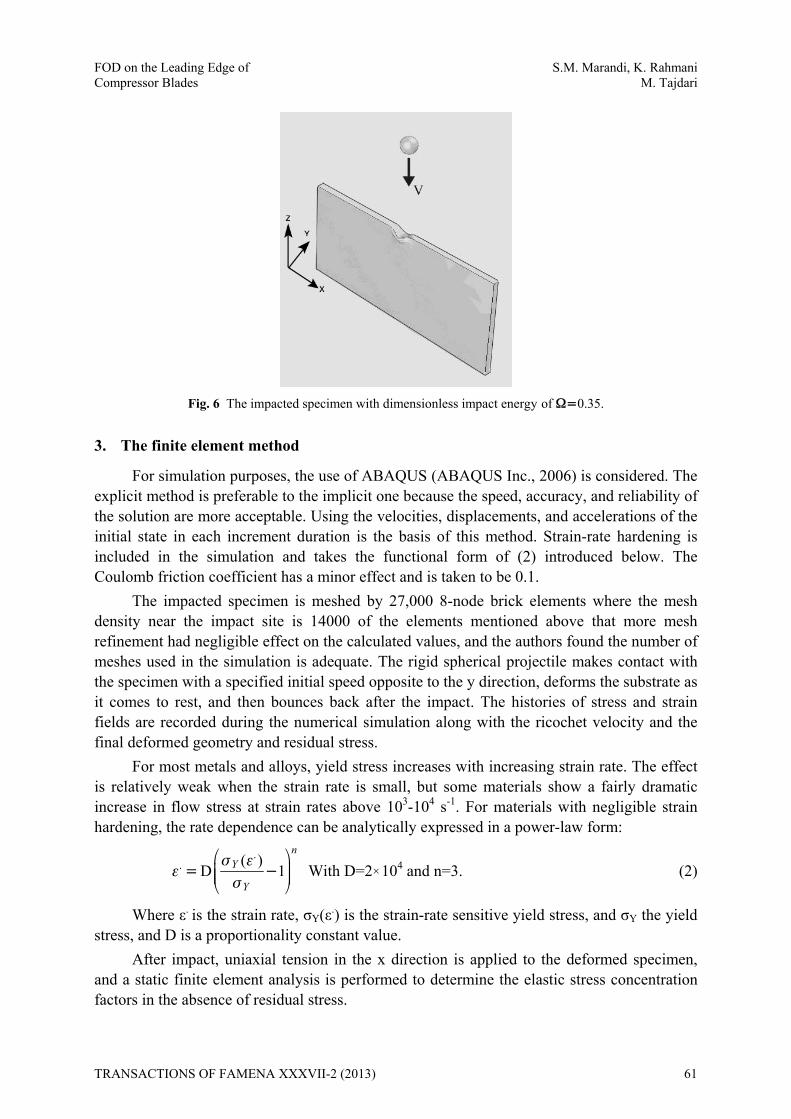
Fig. 6 The impacted specimen with dimensionless impact energy of 0.35.
3. The finite element method
For simulation purposes, the use of ABAQUS (ABAQUS Inc., 2006) is considered. The explicit method is preferable to the implicit one because the speed, accuracy, and reliability of the solution are more acceptable. Using the velocities, displacements, and accelerations of the initial state in each increment duration is the basis of this method. Strain-rate hardening is included in the simulation and takes the functional form of (2) introduced below. The Coulomb friction coefficient has a minor effect and is taken to be 0.1.
The impacted specimen is meshed by 27,000 8-node brick elements where the mesh density near the impact site is 14000 of the elements mentioned above that more mesh refinement had negligible effect on the calculated values, and the authors found the number of meshes used in the simulation is adequate. The rigid spherical projectile makes contact with the specimen with a specified initial speed opposite to the y direction, deforms the substrate as it comes to rest, and then bounces back after the impact. The histories of stress and strain fields are recorded during the numerical simulation along with the ricochet velocity and the final deformed geometry and residual stress.
For most metals and alloys, yield stress increases with increasing strain rate. The effect is relatively weak when the strain rate is small, but some materials show a fairly dramatic increase in flow stress at strain rates above 103-104 s-1. For materials with negligible strain hardening, the rate dependence can be analytically expressed in a power-law form:
.. ( )
D 1
nY
Y
With D=2104 and n=3. (2)
Where ε. is the strain rate, σY(ε.) is the strain-rate sensitive yield stress, and σY the yield stress, and D is a proportionality constant value.
After impact, uniaxial tension in the x direction is applied to the deformed specimen, and a static finite element analysis is performed to determine the elastic stress concentration factors in the absence of residual stress.
TRANSACTIONS OF FAMENA XXXVII-2 (2013) 61

S.M. Marandi, K. Rahmani FOD on the Leading Edge of M. Tajdari Compressor Blades
4. Numerical results
4.1 Residual penetration
The residual penetration as a function of dimensionless impact energy is presented in Fig. 7. It can be observed from Fig. 7 that the relationship between δ/D and Ω1/2 is quadratic. Fig. 8 gives the dependence of the bulge width that increases linearly with δ/D.
Fig. 7 Residual penetration, δ/D, as a function of dimensionless impact energy, Ω1/2.
Fig. 8 Bulge width b/t is plotted as a function of normalized penetration δ/D.
4.2 The elastic stress concentration
The elastic stress concentration is applied after impact. This factor is defined as the proportion of the stress at the region, local stress, to the one away from the geometry discontinuity, namely, kt=σ local/σ, where σ is the remote stress. Critical locations are at the crater floor and rim (A and B in Fig. 10). Stress concentration factors at these two locations are presented in Fig. 9.
62 TRANSACTIONS OF FAMENA XXXVII-2 (2013)
FOD on the Leading Edge of S.M. Marandi, K. Rahmani Compressor Blades M. Tajdari
Fig. 9 Elastic stress concentration factor, kt, as a function of δ/D at crater floor and rim
(A and B in Fig. 10 respectively).
Fig. 10 Three most likely fatigue cracking sites are denoted by A, B and C respectively [8].
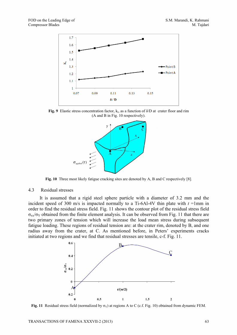
4.3 Residual stresses
It is assumed that a rigid steel sphere particle with a diameter of 3.2 mm and the incident speed of 300 m/s is impacted normally to a Ti-6Al-4V thin plate with t =1mm in order to find the residual stress field. Fig. 11 shows the contour plot of the residual stress field σxx/σY obtained from the finite element analysis. It can be observed from Fig. 11 that there are two primary zones of tension which will increase the load mean stress during subsequent fatigue loading. These regions of residual tension are: at the crater rim, denoted by B, and one radius away from the crater, at C. As mentioned before, in Peters’ experiments cracks initiated at two regions and we find that residual stresses are tensile, c-f. Fig. 11.
Fig. 11 Residual stress field (normalized by σY) at regions A to C (c.f. Fig. 10) obtained from dynamic FEM.
TRANSACTIONS OF FAMENA XXXVII-2 (2013) 63

S.M. Marandi, K. Rahmani FOD on the Leading Edge of M. Tajdari Compressor Blades
The earliest work considered the quasi-static, the normal impression of a hard spherical particle into a thick elastic-plastic substrate [9]. As sketched in Fig. 12, a rigid sphere of diameter D is pushed into a half-space specimen (infinitely-deep specimen that acts as a half-space one) by a static load P. The indentation load is then removed, the contact diameter is w and the indent depth is δ, both measured after unloading. The half-space specimen is taken to be initially stress-free and infinitely deep, consistent with the assumption that the foreign object damage is small compared to the substrate thickness [10]. The functional form (3) introduces the experimental relationship between the static load P and the indent depth δ.
u 3.45 ( )P D (3)
Fig. 12 Schematic of normal impression of steel spherical particle into thick elastic-plastic substrate by static load P [6].
In Eq. (3), σu is ultimate tensile stress. For the Ti-6Al-4V substrate, σu=930 MPa is considered. This can be seen in Fig. 13 where the residual stresses at the critical locations A-C are plotted as a function of δ/D for both quasi-static indentation and fully dynamic impact. The comparison shows that the stresses caused by static and dynamic indents are quite close, except at the crater floor of deep impacts. The important conclusion to be drawn from Fig. 13 is that tensile stresses at locations B and C do not depend strongly on the dynamic aspects of the impact when the depth of penetration, δ/D, is used to determine the residual stress.
Fig. 13 Comparison between static and dynamic residual stresses at critical locations
A, B and C. Residual stresses primarily depend on δ/D.
64 TRANSACTIONS OF FAMENA XXXVII-2 (2013)

FOD on the Leading Edge of S.M. Marandi, K. Rahmani Compressor Blades M. Tajdari
5. Conclusions
Based on the numerical, finite element analysis and the evaluation of a spherical hard-body impact on a thin plate in a Ti-6Al-4V alloy, the following conclusions have been made:
1) The main finding from the first part of the study on dynamic impact is that the normalized depth, δ/D, primarily depends on a single dimensionless kinetic energy parameter, Ω=KE/(σYD3)=π/12(ρP/σY) 2
0v . Typical values of this parameter for FOD
cover the range 0.05 to 0.5 for compressor blade application.
2) FOD creates stress-raising indents that change the local stress pattern in the vicinity of the impact sites under applied load. Stress concentration amplifies the stress magnitude of cyclic fatigue loading. For FOD on the leading edge of a blade, the stress concentration reaches the maximum at the center of the crater floor (A in Fig. 10), and is responsible for fatigue cracking.
3) The residual stress distribution associated with a spherical hard-body impact has been modelled by using the quasi-static and dynamic FEM analysis. The comparison shows that stresses caused by static and dynamic indents are quite close, except at the crater floor of deep indents.
4) The quasi-static and dynamic FEM analyses show that the tensile stresses at the crater rim and outside the rim do not depend strongly on dynamic aspects of the impact when the depth of penetration, δ/D, is used to determine the residual stress.
5) The FEM results show that cracks seen at the crater rim and indent bottom in Peters’ experiments are due to the combination of residual tensile stresses and the elastic stress concentration, which is obtained for different residual penetrations.
6) In fact, fatigue cracking has been seen at three regions, at the crater floor, A, outside the crater rim, at B, and one crater radius away from the crater, at C. Residual tensile stresses are responsible for fatigue cracking at B and C while fatigue cracking at A is induced by elastic stress concentration only.
7) The more δ/D in deep indents, the more intense compressive stresses at the crater base prevent from crack propagation.
ACKNOWLEDGMENT
The authors wish to thank the Power and Water University of Technology for supporting the work described here.
REFERENCES
[1] D. Nowell, P. Duó, I.F. Stewart. Prediction of fatigue performance in gas turbine blades after foreign object damage. International Journal of Fatigue, 25 (2003) 963-969.
[2] P.G. Frankel, P.J. Withers , M. Preuss , H.-T. Wang, J. Tong , D. Rugg. Residual stress fields after FOD impact on flat and airfoil-shaped leading edges. Mechanics of Materials, 55 (2012) 130–145.
[3] Lucjan Witek. Numerical stress and crack initiation analysis of the compressor blades after foreign object damage subjected to high-cycle fatigue. Engineering Failure Analysis, 18 (2011) 2111–2125.
[4] Cowles BA. High cycle fatigue in gas turbine engines-an industry perspective. International Journal of Fracture, 80 (1996) 147-163.
[5] Hamrick ІІ JL, Mall S, Nicholas T. High cycle fatigue life of Ti-6Al-4V after being subjected to foreign object damage. Fourth National Turbine Engine HCF Conference, Monterey, California, USA, (1999, February 9-11).
[6] Xi Chen, Foreign object damage and fatigue cracking. PhD Thesis, Division of engineering and applied science department of Harvard University, (2001).
TRANSACTIONS OF FAMENA XXXVII-2 (2013) 65

S.M. Marandi, K. Rahmani FOD on the Leading Edge of M. Tajdari Compressor Blades
[7] B. L. Boyce, A. W. Thompson, O. Roder, and R.O. Ritchie. Measurement of residual stresses in impact damage Ti-6Al-4V. Fourth National Turbine Engine HCF Conference, Monterey, California, USA, (1999, February 9-11).
[8] Seyed Masoud Marandi, Investigation of elastic stress concentration factor due to FOD on the leading edge of gas turbine blade using FEM and photoelasticity test. MSc Thesis, Energy and mechanical department of Power and Water University of Technology, (2008).
[9] Y. K. Li, Y Mei, W. Duó, and W. Renzhi. Mechanical approach to the residual stress field induced by shot peening. International Journal of Material Science, 23 (1991) 147-161.
[10] C. J. Studman ,and J. E. Field. The indentation of hard metals: the role of residual stresses. International Journal of Material Science, 12 (1997) 215-219.
Submitted: 06.6.2012 Accepted: 16.5.2013
Seyed Masoud Marandi Khosrow Rahmani Mehdi Tajdari Department of Energy and Mechanical Engineering, Power and Water University of Technology Vafadar Exp’Way, Shahid Abbaspour Boulevard, P.O.BOX: 16765-1719 Tehran, Iran
66 TRANSACTIONS OF FAMENA XXXVII-2 (2013)